Embed Size (px)
Citation preview

ms, e
es, ts, n for st lly y ce
n ps
5. Steel and Cast Iron(Systematic Rehabilitation)
5.1 Scope
Rehabilitation measures for steel components and elements are described in this chapter. Information needed for systematic rehabilitation of steel buildings, as depicted in Step 4B of the Process Flow chart shown in Figure 1-1, is presented herein. A brief historical perspective is given in Section 5.2, with a more expanded version given in the Commentary.
Section 5.3 discusses material properties for new and existing construction, and describes material testing requirements for using the nonlinear procedures. A factor measuring the reliability of assumptions of in-place material properties is included in a kappa (κ) factor, used to account for accuracy of knowledge of the existing conditions. Evaluation methods for in-place materials are also described.
Sections 5.4 and 5.5 provide the attributes of steel moment frames and braced frames. The stiffness and strength properties of each steel component required for the linear and nonlinear procedures described in Chapter 3 are given. Stiffness and strength acceptance criteria are also given and are discussed within the context of Tables 2-1, 2-3, and 2-4, given in Chapter 2. These sections also provide guidance on choosing an appropriate rehabilitation strategy.
The appropriate procedures for evaluating systems with old and new components are discussed. Steel frames with concrete or masonry infills are briefly discussed, but the behavior of these systems and procedures for estimating the forces in the steel components are given in Chapters 6 (concrete) and 7 (masonry). Steel frames with attached masonry walls are discussed in this chapter and in Chapter 7.
Section 5.8 describes engineering properties for typical diaphragms found in steel buildings. These include bare metal deck, metal deck with composite concrete topping, noncomposite steel deck with concrete topping, horizontal steel bracing, and archaic diaphragms. The properties and behavior of wood diaphragms in steel buildings are presented in Chapter 8.
Engineering properties, and stiffness and strength acceptance criteria for steel piles are given in
Section 5.9. Methods for calculating the forces in thepiles are described in Chapter 4 and in the Commentary to Chapter 5.
5.2 Historical Perspective
The components of steel elements are columns, beabraces, connections, link beams, and diaphragms. Thcolumns, beams, and braces may be built up with platangles, and/or channels connected together with rivebolts, or welds. The material used in older constructiois likely to be mild steel with a specified yield strengthbetween 30 ksi and 36 ksi. Cast iron was often used columns in much older construction (before 1900). Cairon was gradually replaced by wrought iron and thensteel. The connectors in older construction were usuamild steel rivets or bolts. These were later replaced bhigh-strength bolts and welds. The seismic performanof these components will depend heavily on the condition of the in-place material. A more detailed historical perspective is given in Section C5.2 of the Commentary.
As indicated in Chapter 1, great care should be exercised in selecting the appropriate rehabilitation approaches and techniques for application to historicbuildings in order to preserve their unique characteristics.
5.3 Material Properties and Condition Assessment
5.3.1 General
Quantification of in-place material properties and verification of the existing system configuration and condition are necessary to analyze or evaluate a building. This section identifies properties requiring consideration and provides guidelines for their acquisition. Condition assessment is an important aspect of planning and executing seismic rehabilitatioof an existing building. One of the most important stein condition assessment is a visit to the building for visual inspection.
The extent of in-place materials testing and conditionassessment that must be accomplished is related to availability and accuracy of construction and as-built
FEMA 273 Seismic Rehabilitation Guidelines 5-1

Chapter 5: Steel and Cast Iron
(Systematic Rehabilitation)
ent
ls,
w
d ns. ,
to
in
ons
e
of
ds. ies
es ch d
records, the quality of materials used and construction performed, and the physical condition of the structure. Data such as the properties and grades of material used in component and connection fabrication may be effectively used to reduce the amount of in-place testing required. The design professional is encouraged to research and acquire all available records from original construction. The requirements given here are supplemental to those given in Section 2.7.
5.3.2 Properties of In-Place Materials and Components
5.3.2.1 Material Properties
Mechanical properties of component and connection material dictate the structural behavior of the component under load. Mechanical properties of greatest interest include the expected yield (Fye) and tensile (Fte) strengths of base and connection material, modulus of elasticity, ductility, toughness, elogational characteristics, and weldability. The term “expected strength” is used throughout this document in place of “nominal strength” since expected yield and tensile stresses are used in place of nominal values specified in AISC (1994a and b).
The effort required to determine these properties is related to the availability of original and updated construction documents, original quality of construction, accessibility, and condition of materials.
The determination of material properties is best accomplished through removal of samples and laboratory testing. Sampling may take place in regions of reduced stress—such as flange tips at beam ends and external plate edges—to minimize the effects of reduced area. Types and sizes of specimens should be in accordance with ASTM standards. Mechanical and metallurgical properties usually can be established from laboratory testing on the same sample. If a connector such as a bolt or rivet is removed for testing, a comparable bolt should be reinstalled at the time of sampling. Destructive removal of a welded connection sample must be accompanied by repair of the connection.
5.3.2.2 Component Properties
Behavior of components, including beams, columns, and braces, is dictated by such properties as area, width-to-thickness and slenderness ratios, lateral torsional
buckling resistance, and connection details. Componproperties of interest are:
• Original cross-sectional shape and physical dimensions
• Size and thickness of additional connected materiaincluding cover plates, bracing, and stiffeners
• Existing cross-sectional area, section moduli, moments of inertia, and torsional properties at critical sections
• As-built configuration of intermediate, splice, and end connections
• Current physical condition of base metal and connector materials, including presence of deformation.
Each of these properties is needed to characterize building performance in the seismic analysis. The starting point for establishing component properties should be construction documents. Preliminary revieof these documents shall be performed to identify primary vertical- and lateral-load-carrying elements ansystems, and their critical components and connectioIn the absence of a complete set of building drawingsthe design professional must direct a testing agency perform a thorough inspection of the building to identify these elements and components as indicatedSection 5.3.3.
In the absence of degradation, statistical analysis hasshown that mean component cross-sectional dimensiare comparable to the nominal published values by AISC, AISI, and other organizations. Variance in thesdimensions is also small.
5.3.2.3 Test Methods to Quantify Properties
To obtain the desired in-place mechanical properties materials and components, it is necessary to utilize proven destructive and nondestructive testing methoTo achieve the desired accuracy, mechanical propertshould be determined in the laboratory. Particular laboratory test information that may be sought includyield and tensile strength, elongation, and charpy nottoughness. For each test, industry standards publisheby the ASTM exist and shall be followed. The Commentary provides applicability information and references for these particular tests.
5-2 Seismic Rehabilitation Guidelines FEMA 273

Chapter 5: Steel and Cast Iron
(Systematic Rehabilitation)
a m ill
e
ly
s.
e by d
r
of is th
eu
ns
Of greatest interest to metal building system performance are the expected yield and tensile strength of the installed materials. Notch toughness of structural steel and weld material is also important for connections that undergo cyclic loadings and deformations during earthquakes. Chemical and metallurgical properties can provide information on properties such as compatibility of welds with parent metal and potential lamellar tearing due to through-thickness stresses. Virtually all steel component elastic and inelastic limit states are related to yield and tensile strengths. Past research and accumulation of data by industry groups have resulted in published material mechanical properties for most primary metals and their date of fabrication. Section 5.3.2.5 provides this strength data. This information may be used, together with tests from recovered samples, to rapidly establish expected strength properties for use in component strength and deformation analyses.
Review of other properties derived from laboratory tests—such as hardness, impact, fracture, and fatigue—is generally not needed for steel component capacity determination, but is required for archaic materials and connection evaluation. These properties may not be needed in the analysis phase if significant rehabilitative measures are already known to be required.
To quantify material properties and analyze the performance of welded moment connections, more extensive sampling and testing may be necessary. This testing may include base and weld material chemical and metallurgical evaluation, expected strength determination, hardness, and charpy V-notch testing of the heat-affected zone and neighboring base metal, and other tests depending on connection configuration.
If any rehabilitative measures are needed and welded connection to existing components is required, the carbon equivalent of the existing component(s) shall be determined. Appropriate welding procedures are dependent upon the chemistry of base metal and filler material (for example, the elements in the IIW Carbon Equivalent formula). Consult Section 8 and its associated Commentary in the latest edition of ANSI/AWS D1.1 Structural Welding Code. Recommendations given in FEMA 267 (SAC, 1995) may also be followed.
5.3.2.4 Minimum Number of Tests
In order to quantify expected strength and other in-place properties accurately, it will sometimes be required that
a minimum number of tests be conducted on representative components. As stated previously, theminimum number of tests is dictated by available datfrom original construction, the type of structural systeemployed, desired accuracy, and quality/condition ofin-place materials. Access to the structural system walso be a factor in defining the testing program. As analternative, the design professional may elect to utilizthe default strength properties contained in Section 5.3.2.5 instead of the specified testing. However, in some cases these default values may onbe used for a Linear Static Procedure (LSP).
Material properties of structural steel vary much less than those of other construction materials. In fact, theexpected yield and tensile stresses are usually considerably higher than the nominal specified valueAs a result, testing for material properties may not berequired. The properties of wrought iron are more variable than those of steel. The strength of cast ironcomponents cannot be determined from small sampltests, since component behavior is usually governedinclusions and other imperfections. It is recommendethat the lower-bound default value for compressive strength of cast iron given in Table 5-1 be used.
The guidelines for determining the expected yield (Fye) and tensile (Fte) strengths are given below.
• If original construction documents defining properties—including material test records or material test reports (MTR)—exist, material tests need not be carried out, at the discretion of the design professional. Default values from Table 5-2may be used. Larger values may be used, at the discretion of the design professional, if available historical data substantiates them. Larger values should be used if the assumptions produce a largedemand on associated connections.
• If original construction documents defining properties are limited or do not exist, but the date construction is known and the single material usedconfirmed to be carbon steel, at least three strengcoupons shall be randomly removed from each component type. Conservative material propertiessuch as those given in Table 5-2 may be used in liof testing, at the discretion of the design professional.
• If no knowledge exists of the structural system andmaterials used, at least two strength tensile coupo
FEMA 273 Seismic Rehabilitation Guidelines 5-3

Chapter 5: Steel and Cast Iron
(Systematic Rehabilitation)
l
t
he rd
ve.
-2.
in
ve th
ite
are:
,
should be removed from each component type for every four floors. If it is determined from testing that more than one material grade exists, additional testing should be performed until the extent of use for each grade in component fabrication has been established. If it is determined that all components are made from steel, the requirements immediately preceding this may be followed.
• In the absence of construction records defining welding filler metals and processes used, at least one weld metal sample for each construction type should be obtained for laboratory testing. The sample shall consist of both local base and weld metal, such that composite strength of the connection can be derived. Steel and weld filler material properties discussed in Section 5.3.2.3 should also be obtained. Because of the destructive nature and necessary repairs that follow, default strength properties may be substituted if original records on welding exist, unless the design professional requires more accurate data. If ductility and toughness are required at or near the weld, the design professional may conservatively assume that no ductility is available, in lieu of testing. In this case the joint would have to be modified. Special requirements for welded moment frames are given in FEMA 267 (SAC, 1995) and the latest edition of ANSI/AWS D1.1 Structural Welding Code.
• Testing requirements for bolts and rivets are the same as for other steel components as given above. In lieu of testing, default values from Table 5-2 may be used.
• For archaic materials, including wrought iron but excluding cast iron, at least three strength coupons shall be extracted for each component type for every four floors of construction. Should significant variability be observed, in the judgment of the design professional, additional tests shall be performed until an acceptable strength value is obtained. If initial tests provide material properties that are consistent with properties given in Table 5-1, tests are required only for every six floors of construction.
For all laboratory test results, the mean yield and tensile strengths may be interpreted as the expected strength for component strength calculations.
For other material properties, the design professionashall determine the particular need for this type of testing and establish an adequate protocol consistenwith that given above. In general, it is recommended that a minimum of three tests be conducted.
If a higher degree of confidence in results is desired, tsample size shall be determined using ASTM StandaE22 guidelines. Alternatively, the prior knowledge of material grades from Section 5.3.2.5 may be used in conjunction with Bayesian statistics to gain greater confidence with the reduced sample sizes noted aboThe design professional is encouraged to use the procedures contained in the Commentary in this regard.
5.3.2.5 Default Properties
The default expected strength values for key metallicmaterial properties are contained in Tables 5-1 and 5These values are conservative, representing mean values from previous research less two standard deviations. It is recommended that the results of any material testing performed be compared to values in these tables for the particular era of building construction. Additional testing is recommended if theexpected yield and tensile strengths determined fromtesting are lower than the default values.
Default material strength properties may only be usedconjunction with Linear Static and Dynamic Procedures. For the nonlinear procedures, expected strengths determined from the test program given aboshall be used. Nonlinear procedures may be used withe reduced testing requirements described in Commentary Section C5.3.2.5.
5.3.3 Condition Assessment
5.3.3.1 General
A condition assessment of the existing building and sconditions shall be performed as part of the seismic rehabilitation process. The goals of this assessment
• To examine the physical condition of primary and secondary components and the presence of any degradation
• To verify or determine the presence and configuration of components and their connectionsand the continuity of load paths between components, elements, and systems
5-4 Seismic Rehabilitation Guidelines FEMA 273

Chapter 5: Steel and Cast Iron
(Systematic Rehabilitation)
ne
nt.
. d d.
• To review other conditions—such as neighboring party walls and buildings, the presence of nonstructural components, and limitations for rehabilitation—that may influence building performance
• To formulate a basis for selecting a knowledge factor (see Section 5.3.4).
The physical condition of existing components and elements, and their connections, must be examined for presence of degradation. Degradation may include environmental effects (e.g., corrosion, fire damage, chemical attack) or past/current loading effects (e.g.,
overload, damage from past earthquakes, fatigue, fracture). The condition assessment shall also examifor configurational problems observed in recent earthquakes, including effects of discontinuous components, improper welding, and poor fit-up.
Component orientation, plumbness, and physical dimensions should be confirmed during an assessmeConnections in steel components, elements, and systems require special consideration and evaluationThe load path for the system must be determined, aneach connection in the load path(s) must be evaluateThis includes diaphragm-to-component and component-to-component connections. FEMA 267
Table 5-1 Default Material Properties 1
Early unit stresses used in tables of allowable loads as published in catalogs of the following mills
FOR CAST IRON1
Year Rolling MillExpected Yield Strength, ksi
1873 Carnegie Kloman & Co. (“Factor of Safety 3”) 21
1874 New Jersey Steel & Iron Co. 18
1881–1884 Carnegie Brothers & Co., Ltd. 1815
1884 The Passaic Rolling Mill Co. 1815
1885 The Phoenix Iron Company 18
1885–1887 Pottsville Iron & Steel Co. 18
1889 Carnegie Phipps & Co., Ltd. 1815
FOR STEEL1
1887 Pottsville Iron & Steel Co. 23
1889–1893 Carnegie Phipps & Co., Ltd. 24
1893–1908 Jones & Laughlins Ltd.Jones & Laughlins Steel Co.
2418
1896 Carnegie Steel Co., Ltd. 24
1897–1903 The Passaic Rolling Mills Co. 2418
1898–1919 Cambria Steel Co. 2418
1900–1903 Carnegie Steel Company 24
1907–1911 Bethlehem Steel Co. 24
1915 Lackawanna Steel Co. 2418
1. Modified from unit stress values in AISC “Iron and Steel Beams from 1873 to 1952.”
FEMA 273 Seismic Rehabilitation Guidelines 5-5

Chapter 5: Steel and Cast Iron
(Systematic Rehabilitation)
Table 5-2 Default Expected Material Strengths 1
History of ASTM and AISC Structural Steel Specification Stresses
Date Specification Remarks
ASTM Requirement
Expected Tensile Strength 2, Fte, ksi
Expected Yield Strength 2, 3
Fye, ksi
1900 ASTM, A9
Buildings
Rivet Steel
Medium Steel
50
60
30
35
1901–1908 ASTM, A9
Buildings
Rivet Steel
Medium Steel
50
60
1/2 T.S.
1/2 T.S.
1909–1923 ASTM, A9
Buildings
Structural Steel
Rivet Steel
55
48
1/2 T.S.
1/2 T.S.
1924–1931 ASTM, A7 Structural Steel 55 1/2 T.S. or not less than 30
Rivet Steel 46 1/2 T.S. or not less than 25
ASTM, A9 Structural Steel 55 1/2 T.S. or not less than 30
Rivet Steel 46 1/2 T.S. or not less than 25
1932 ASTM, A140-32T issued as a tentative revision to ASTM, A9 (Buildings)
Plates, Shapes, Bars 60 1/2 T.S. or not less than 33
Eyebar flats unannealed
67 1/2 T.S. or not less than 36
1933 ASTM, A140-32T discontinued and ASTM, A9 (Buildings) revisedOct. 30, 1933
Structural Steel 55 1/2 T.S. or not less than 30
ASTM, A9 tentatively revised to ASTM, A9-33T (Buildings)
Structural Steel 60 1/2 T.S. or not less than 33
ASTM, A141-32T adopted as a standard
Rivet Steel 52 1/2 T.S. or not less than 28
1934 on ASTM, A9 Structural Steel 60 1/2 T.S. or not less than 33
ASTM, A141 Rivet Steel 52 1/2 T.S. or not less than 28
1. Duplicated from AISC “Iron and Steel Beams 1873 to 1952.”
2. Values shown in this table are based on mean minus two standard deviations and duplicated from “Statistical Analysis of Tensile Data for Wide-Flange Structural Shapes.” The values have been reduced by 10%, since originals are from mill tests.
3. T.S. = Tensile strength
5-6 Seismic Rehabilitation Guidelines FEMA 273

Chapter 5: Steel and Cast Iron
(Systematic Rehabilitation)
l pe n .
st
al f al
(SAC, 1995) provides recommendations for inspection of welded steel moment frames.
The condition assessment also affords an opportunity to review other conditions that may influence steel elements and systems and overall building performance. Of particular importance is the identification of other elements and components that may contribute to or impair the performance of the steel system in question, including infills, neighboring buildings, and equipment attachments. Limitations posed by existing coverings, wall and ceiling space, infills, and other conditions shall also be defined such that prudent rehabilitation measures may be planned.
5.3.3.2 Scope and Procedures
The scope of a condition assessment shall include all primary structural elements and components involved in gravity and lateral load resistance. The degree of
assessment performed also affects the κ factor that is used (see Section 5.3.4).
If coverings or other obstructions exist, indirect visuainspection through use of drilled holes and a fiberscomay be utilized. If this method is not appropriate, thelocal removal of covering materials will be necessaryThe following guidelines shall be used.
• If detailed design drawings exist, exposure of at leaone different primary connection shall occur for each connection type. If no deviations from the drawings exist, the sample may be considered representative. If deviations are noted, then removof additional coverings from primary connections othat type must be done until the design professionhas adequate knowledge to continue with the evaluation and rehabilitation.
Additional default assumptions
Date Specification RemarksExpected Tensile Strength 2, Fte, ksi
Expected Yield Strength 2, 3 Fye, ksi
1961 on ASTM, A36
Group 1
Group 2
Group 3
Group 4
Group 5
Structural Steel
54
52
52
53
61
37
35
32
30
35
ASTM, A572, Grade 50
Group 1
Group 2
Group 3
Group 4
Group 5
Structural Steel
56
57
60
62
71
41
42
44
43
44
Dual Grade
Group 1
Group 2
Group 3
Group 4
Structural Steel
59
60
64
64
43
43
46
44
Table 5-2 Default Expected Material Strengths 1 (continued)
1. Duplicated from AISC “Iron and Steel Beams 1873 to 1952.”
2. Values shown in this table are based on mean minus two standard deviations and duplicated from “Statistical Analysis of Tensile Data for Wide-Flange Structural Shapes.” The values have been reduced by 10%, since originals are from mill tests.
3. T.S. = Tensile strength
FEMA 273 Seismic Rehabilitation Guidelines 5-7

Chapter 5: Steel and Cast Iron
(Systematic Rehabilitation)
,
d
ary
in
(in
oo
A
d
,
eir
ing
y bal ne n
• In the absence of construction drawings, the design professional shall establish inspection protocol that will provide adequate knowledge of the building needed for reliable evaluation and rehabilitation. For steel elements encased in concrete, it may be more cost effective to provide an entirely new lateral-load-resisting system.
Physical condition of components and connectors may also dictate the use of certain destructive and nondestructive test methods. If steel elements are covered by well-bonded fireproofing materials or encased in durable concrete, it is likely that their condition will be suitable. However, local removal of these materials at connections shall be performed as part of the assessment. The scope of this removal effort is dictated by the component and element design. For example, in a braced frame, exposure of several key connections may suffice if the physical condition is acceptable and configuration matches the design drawings. However, for moment frames it may be necessary to expose more connection points because of varying designs and the critical nature of the connections. See FEMA 267 (SAC, 1995) for inspection of welded moment frames.
5.3.3.3 Quantifying Results
The results of the condition assessment shall be used in the preparation of building system models in the evaluation of seismic performance. To aid in this effort, the results shall be quantified and reduced, with the following specific topics addressed:
• Component section properties and dimensions
• Connection configuration and presence of any eccentricities
• Type and location of column splices
• Interaction of nonstructural components and their involvement in lateral load resistance
The acceptance criteria for existing components depends on the design professional’s knowledge of the condition of the structural system and material properties (as previously noted). All deviations noted between available construction records and as-built conditions shall be accounted for and considered in the structural analysis.
5.3.4 Knowledge (κ) Factor
As described in Section 2.7 and Tables 2-16 and 2-17computation of component capacities and allowable deformations shall involve the use of a knowledge (κ) factor. For cases where a linear procedure will be usein the analysis, two categories of κ exist. This section further describes the requirements specific to metallicstructural elements that must be accomplished in theselection of a κ factor.
A κ factor of 1.0 can be utilized when a thorough assessment is performed on the primary and secondcomponents and load path, and the requirements of Section 2.7 are met. The additional requirement for aκ factor of 1.0 is that the condition assessment be doneaccordance with Section 5.3.3. In general, a κ factor of 1.0 may be used if the construction documents are available.
If the configuration and condition of an as-built component or connection are not adequately known the judgement of the design professional, because design documents are unavailable and it is deemed tcostly to do a thorough condition assessment in accordance with Section 5.3.3), the κ factor used in the final component evaluation shall be reduced to 0.75. κ factor of 0.75 shall be used for all cast and wroughtiron components and their connectors. For encased components where construction documents are limiteand knowledge of configuration and condition is incomplete, a factor of 0.75 shall be used. In additionfor steel moment and braced frames, the use of a κ factor of 0.75 shall occur when knowledge of connection details is incomplete. See also Section C2.7.2 in the Commentary.
5.4 Steel Moment Frames
5.4.1 General
Steel moment frames are those frames that develop thseismic resistance through bending of beams and columns and shearing of panel zones. Moment-resistconnections with calculable resistance are required between the members. The frames are categorized bthe types of connection used and by the local and glostability of the members. Moment frames may act aloto resist seismic loads, or they may act in conjunctionwith concrete or masonry shear walls or braced steelframes to form a dual system. Special rules for desig
5-8 Seismic Rehabilitation Guidelines FEMA 273

Chapter 5: Steel and Cast Iron
(Systematic Rehabilitation)
re se
ms
ll
ate
all
of
d o ty nter
ter
ly
of new dual systems are included in AISC (1994a) and BSSC (1995).
Columns, beams, and connections are the components of moment frames. Beams and columns may be built-up members from plates, angles, and channels, cast or wrought iron segments, hot-rolled members, or cold-formed steel sections. Built-up members may be assembled by riveting, bolting, or welding. Connections between the members may be fully restrained (FR), partially restrained (PR), or nominally unrestrained (simple shear or pinned). The components may be bare steel, steel with a nonstructural coating for fire protection, or steel with either concrete or masonry encasement for fire protection.
Two types of frames are categorized in this document. Fully restrained (FR) moment frames are those frames for which no more than 5% of the lateral deflections arise from connection deformation. Partially restrained (PR) moment frames are those frames for which more than 5% of the lateral deflections result from connection deformation. In each case, the 5% value refers only to deflection due to beam-column deformation and not to frame deflections that result from column panel zone deformation.
5.4.2 Fully Restrained Moment Frames
5.4.2.1 General
Fully restrained (FR) moment frames are those moment frames with rigid connections. The connection shall be at least as strong as the weaker of the two members being joined. Connection deformation may contribute no more than 5% (not including panel zone deformation) to the total lateral deflection of the frame. If either of these conditions is not satisfied, the frame shall be characterized as partially restrained. The most common beam-to-column connection used in steel FR moment frames since the late 1950s required the beam flange to be welded to the column flange using complete joint penetration groove welds. Many of these connections have fractured during recent earthquakes. The design professional is referred to the Commentary and to FEMA 267 (SAC, 1995).
Fully restrained moment frames encompass both Special Moment Frames and Ordinary Moment Frames, defined in the Seismic Provisions for Structural Steel Buildings in Part 6 of AISC (1994a). These terms are not used in the Guidelines, but most of the requirements for these systems are reflected in AISC (1994a).
Requirements for general or seismic design of steel components given in AISC (1994a) or BSSC (1995) ato be followed unless superseded by provisions in theGuidelines. In all cases, the expected strength will be used in place of the nominal design strength by replacing Fy with Fye.
5.4.2.2 Stiffness for Analysis
A. Linear Static and Dynamic Procedures
Axial area. This is the complete area of rolled or built-up shapes. For built-up sections, the effective area should be reduced if adequate load transfer mechanisare not available. For elements fully encased in concrete, the stiffness may be calculated assuming fucomposite action if most of the concrete may be expected to remain after the earthquake. Composite action may not be assumed for strength unless adequload transfer and ductility of the concrete can be assured.
Shear area. This is based on standard engineering procedures. The above comments, related to built-upsections, concrete encased elements, and compositeaction of floor beam and slab, apply.
Moment of inertia. The calculation of rotational stiffness of steel beams and columns in bare steel frames shall follow standard engineering procedures.For components encased in concrete, the stiffness shinclude composite action, but the width of the composite section shall be taken as equal to the widththe flanges of the steel member and shall not includeparts of the adjoining floor slab, unless there is an adequate and identifiable shear transfer mechanism between the concrete and the steel.
Joint Modeling. Panel zone stiffness may be considerein a frame analysis by adding a panel zone element tthe program. The beam flexural stiffness may also beadjusted to account for panel zone stiffness or flexibiliand the stiffness of the concrete encasement. Use celine analysis for other cases. Strengthened membersshall be modeled similarly to existing members. The approximate procedure suggested for calculation of stiffness of PR moment frames given below may be used to model panel zone effects, if available compuprograms cannot explicitly model panel zones.
Connections. The modeling of stiffness for connectionsfor FR moment frames is not required since, by definition, the frame displacements are not significant
FEMA 273 Seismic Rehabilitation Guidelines 5-9

Chapter 5: Steel and Cast Iron
(Systematic Rehabilitation)
r
f
(<5%) affected by connection deformation. The strength of the connection must be great enough to carry the expected moment strength and resulting shear in the beam at a beam-to-column connection and shall be calculated using standard engineering procedures. Three types of connections are currently acknowledged as potentially fully restrained: (1) full penetration (full-pen) welds between the flanges of the beam and column flanges with bolted or welded shear connections between the column flange and beam web; (2) flange plate connections; and (3) end plate connections. If flange plate or end plate connections are too flexible or weak to be considered fully restrained, they must be considered to be partially restrained. Strength and stiffness properties for these two connections as PR connections are discussed in Section 5.4.3 and in the Commentary.
B. Nonlinear Static Procedure
• Use elastic component properties as outlined under Section 5.4.2.2A.
• Use appropriate nonlinear moment-curvature and interaction relationships for beams and beam-columns to represent plastification. These may be derived from experiment or analysis.
• Linear and nonlinear behavior of panel zones shall be included.
In lieu of a more rational analysis, the details of all segments of the load-deformation curve, as defined in Tables 5-4 and Figure 5-1 (an approximate, generalized, load-deformation curve for components of steel moment frames, braced frames, and plate walls), may be used. This curve may be modified by assuming a strain-hardening slope of 3% of the elastic slope. Larger strain-hardening slopes may be used if verified by experiment. If panel zone yielding occurs, a strain-hardening slope of 6% or larger should be used for the panel zone. It is recommended that strain hardening be considered for all components.
The parameters Q and QCE in Figure 5-1 are generalized component load and generalized component expected strength for the component. For beams and columns, θ is the plastic rotation of the beam or column, θy is the rotation at yield, ∆ is displacement, and ∆y is yield displacement. For panel zones, θy is the angular shear deformation in radians. Figure 5-2 defines
chord rotation for beams. The chord rotation may be estimated by adding the yield rotation, θy, to the plastic rotation. Alternatively, the chord rotation may be estimated to be equal to the story drift. Test results fosteel components are often given in terms of chord rotation. The equations for θy given in Equations 5-1 and 5-2 are approximate, and are based on the assumption of a point of contraflexure at mid-length othe beam or column.
Beams: (5-1)
Columns: (5-2)
Figure 5-1 Definition of the a, b, c, d, and e Parameters in Tables 5-4, 5-6, and 5-8, and the Generalized Load-Deformation Behavior
A
B C
D E
or
(a) Deformation
a
b
c
1.0
QQCE
(b) Deformation ratio
θ ∆
A
B C
D E
d
e
c
1.0
QQCE
θθy
∆∆y
or
θy
ZFyelb6EIb
----------------=
θy
ZFyelc6EIc
---------------- 1 PPye--------–
=
5-10 Seismic Rehabilitation Guidelines FEMA 273

Chapter 5: Steel and Cast Iron
(Systematic Rehabilitation)
t
n
Q and QCE are the generalized component load and generalized component expected strength, respectively. For beams and columns, these refer to the plastic moment capacity, which is for:
Beams: (5-3)
Columns:
(5-4)
Panel Zones: (5-5)
where
C. Nonlinear Dynamic Procedure
The complete hysteretic behavior of each componenmust be properly modeled. This behavior must be verified by experiment. This procedure is not recommended in most cases.
5.4.2.3 Strength and Deformation Acceptance Criteria
A. Linear Static and Dynamic Procedures
The strength and deformation acceptance criteria forthese methods require that the load and resistance relationships given in Equations 3-18 and 3-19 in Chapter 3 be satisfied. The design strength of components in existing FR moment frames shall be determined using the appropriate equations for desigstrength given in Section 5.4.2.2 or in Part 6 of AISC (1994a), except that φ shall be taken as 1.0. Design restrictions given in AISC (1994a) shall be followed unless specifically superseded by provisions in theseGuidelines.
Evaluation of component acceptability requires knowledge of the component expected strength, QCE, for Equation 3-18 and the component lower-bound strength, QCL , for Equation 3-19, and the component demand modifier, m, as given in Table 5-3 for Equation 3-18. Values for QCE and QCL for FR moment frame components are given in this section. QCE and QCL are used for deformation- and force-controlled components, respectively. Values for m are given in Table 5-3 for the Immediate Occupancy, Life Safety, and Collapse Prevention Performance Levels.
Figure 5-2 Definition of Chord Rotation
dc = Column depth, in.
E = Modulus of elasticity, ksiFye = Expected yield strength of the material, ksi
I = Moment of inertia, in.4
lb = Beam length, in.
L
∆y
∆Chord
θ
(a) Cantilever example
(b) Frame example
= L
θy∆y =
Lθ ∆
Chord Rotation:
∆
θ
= L
θ ∆
QCE MCE ZFye= =
QCE MCE 1.18ZFye 1 PPye--------–
ZFye≤= =
QCE VCE 0.55Fyedctp= =
lc = Column length, in.
MCE = Expected moment strength
P = Axial force in the member, kipsPye = Expected axial yield force of the member =
AgFye, kips
Q = Generalized component loadQCE = Generalized component expected strength
tp = Total panel zone thickness including doublerplates, in.
θ = Chord rotationθy = Yield rotation
VCE = Expected shear strength, kips
Z = Plastic section modulus, in.3
FEMA 273 Seismic Rehabilitation Guidelines 5-11

Chapter 5: Steel and Cast Iron
(Systematic Rehabilitation)
the
in
y t
l
Beams. The design strength of beams and other flexural members is the lowest value obtained according to the limit state of yielding, lateral-torsional buckling, local flange buckling, or shear yielding of the web. For fully concrete-encased beams where the concrete is expected to remain in place, because of confining reinforcement, during the earthquake, assume bf = 0 and Lp = 0 for the purpose of determining m. For bare beams bent about their major axes and symmetric about both axes,
with (compact section) and lb < Lp, the
values for m are given in Table 5-3, and:
(5-6)
where
If and , values for m are given in
Table 5-3. For cases where the moment diagram is nonuniform and Lp < Lb < Lr , but the nominal bending strength is still MpCE, the value of m is obtained from Table 5-3. If MCE < MpCE due to lateral torsional buckling, then the value of m shall be me, where
(5-7)
where
If the beam strength is governed by shear strength of
unstiffened web and , then:
(5-8)
where
For this case, use tabulated values for beams, row a,
Table 5-3. If , the value of VCE should be
calculated from provisions in Part 6 of AISC (1994a) and the value of m should be chosen using engineeringjudgment, but should be less than 8.
The limit state of local flange and lateral torsional buckling are not applicable to components either subjected to bending about their minor axes or fully encased in concrete, with confining reinforcement.
For built-up shapes, the strength may be governed bthe strength of the lacing plates that carry componen
bf = Width of the compression flange, in.
tf = Thickness of the compression flange, in.
lb = Length of beam, in.
Lp = Limiting lateral unbraced length for full plastic bending capacity for uniform bending from AISC (1994a), in.
MCE = Expected flexural strength, kip-in.
MpCE = Expected plastic moment capacity, kip-in.
Fye = Expected mean yield strength determined by the tests or given in Tables 5-1 or 5-2
bf
2tf------ 52
Fye
------------<
QCE MCE MpCE ZFye= = =
bf
2tf------ 52
Fy
----------> lb Lp>
me Cb m m 1–( )Lb Lp–( )Lr Lp–
----------------------– 8≤=
Lb = Distance between points braced against lateradisplacement of the compression flange, or between points braced to prevent twist of the cross section (see AISC, 1994a)
Lp = Limiting unbraced length between points of lateral restraint for the full plastic moment capacity to be effective (see AISC, 1994a)
Lr = Limiting unbraced length between points of lateral support beyond which elastic lateral torsional buckling of the beam is the failure mode (see AISC, 1994a)
m = Value of m given in Table 5-3me = Effective m from Equation 5-7
Cb = Coefficient to account for effect of nonuniform moment (see AISC, 1994a)
VCE = Expected shear strength, kips
Aw = Nominal area of the web = dbtw, in.2
tw = Web thickness, in.
h = Distance from inside of compression flange toinside of tension flange, in.
htw----- 418
Fy
----------≤
QCE VCE 0.6FyeAw= =
htw----- 418
Fy
---------->
5-12 Seismic Rehabilitation Guidelines FEMA 273

Chapter 5: Steel and Cast Iron
(Systematic Rehabilitation)
ng,
d.
ges on
e
e
es,
e
shear. For this case, the lacing plates are not as ductile as the component and should be designed for 0.5 times the m value in Table 5-3, unless larger values can be justified by tests or analysis. For built-up laced beams and columns fully encased in concrete, local buckling of the lacing is not a problem if most of the encasement can be expected to be in place after the earthquake.
Columns. The lower-bound strength, QCL, of steel columns under compression only is the lowest value obtained by the limit stress of buckling, local flange buckling, or local web buckling. The effective design strength should be calculated in accordance with provisions in Part 6 of AISC (1994a), but φ = 1.0 and Fye shall be used for existing components. Acceptance shall be governed by Equation 3-19 of these Guidelines, since this is a force-controlled member.
The lower-bound strength of cast iron columns shall be calculated as:
(5-9)
where
Cast iron columns can only carry axial compression.
For steel columns under combined axial and bending stress, the column shall be considered to be deformation-controlled and the lower-bound strength shall be calculated by Equation 5-10 or 5-11.
For
(5-10)
For
(5-11)
where
For columns under combined compression and bendilateral bracing to prevent torsional buckling shall be provided as required by AISC (1994a).
Panel Zone. The strength of the panel zone shall be calculated as given in Equation 5-5.
Connections. By definition, the strength of FR connections shall be at least equal to, or preferably greater than, the strength of the members being joineSome special considerations should be given to FR connections.
Full Penetration Welded Connections (Full-Pen). Full-pen connections (see Figure 5-3) have the beam flanwelded to the column flanges with complete penetratigroove welds. A bolted or welded shear tab is also included to connect the beam web to the column. Thstrength and ductility of full-pen connections are not fully understood at this time. They are functions of thquality of construction, the lb/db ratio of the beam (where lb = beam length and db = beam depth), the weldmaterial, the thickness of the beam and column flangthe stiffness and strength of the panel zones, joint confinement, triaxial stresses, and other factors (seeSAC, 1995). In lieu of further study, the value of m for Life Safety for beams with full-pen connections shall bnot larger than
PCL AgFcr=
Fcr 12 ksi for l c/r 108≤=
Fcr1.40 10
5×
l c/r( )2
-------------------------ksi for l c/r 108>=
PPCL---------- 0.2≥
PPCL---------- 8
9---
Mx
mxMCEx---------------------
My
myMCEy---------------------+ 1.0≤+
PPCL--------- 0.2<
P = Axial force in the column, kipsPCL = Expected compression strength of the
column, kipsMx = Bending moment in the member for the x-
axis, kip-inMCEx = Expected bending strength of the column for
the x-axis, kip-inMCEy = Expected bending strength of the column for
the y-axisMy = Bending moment in the member for the y-
axis, kip-inmx = Value of m for the column bending about the
x-axismy = Value of m for the column bending about the
y-axis
P2PCL-------------
Mx
mxMCEx---------------------
My
myMCEy--------------------- 1.0≤+ +
FEMA 273 Seismic Rehabilitation Guidelines 5-13

Chapter 5: Steel and Cast Iron
(Systematic Rehabilitation)
Table 5-3 Acceptance Criteria for Linear Procedures—Fully Restrained (FR) Moment Frames
Component/Action
m Values for Linear Procedures 8
Primary Secondary
IOm
LSm
CPm
LSm
CPm
Moment FramesBeams:
a. 2 6 8 10 12
b. 1 2 3 3 4
c. For use linear interpolation
Columns:For P/Pye < 0.20
a. 2 6 8 10 12
b. 1 1 2 2 3
c. For use linear interpolation
For 0.2 ð P/Pye ð 0.509
a. 1 —1 —2 —3 —4
b. 1 1 1.5 2 2
c. For use linear interpolation
Panel Zones 1.5 8 11 NA NA
Fully Restrained Moment Connections 7
For full penetration flange welds and bolted or welded web connection: beam deformation limits a. No panel zone yield 1 —5 —6 3 4
b. Panel zone yield 0.8 2 2.5 2 2.5
1. m = 9 (1 – 1.7 P/Pye)2. m = 12 (1 – 1.7 P/Pye)3. m = 15 (1 – 1.7 P/Pye)4. m = 18 (1 – 1.7 P/Pye)5. m = 6 – 0.125 db 6. m = 7 – 0.125 db 7. If construction documents verify that notch-tough rated weldment was used, these values may be multiplied by two.8. For built-up numbers where strength is governed by the facing plates, use one-half these m values.9. If P/Pye > 0.5, assume column to be force-controlled.
b2tf------ 52
Fye
------------<
b2tf------ 95
Fye
------------>
52
Fye
------------ b2tf------ 95
Fye
------------≤ ≤
b2tf------ 52
Fye
------------<
b2tf------ 95
Fye
------------>
52
Fye
------------ b2tf------ 95
Fye
------------≤ ≤
b2tf------ 52
Fye
------------<
b2tf------ 95
Fye
------------>
52
Fye
------------ b2tf------ 95
Fye
------------≤ ≤
5-14 Seismic Rehabilitation Guidelines FEMA 273

Chapter 5: Steel and Cast Iron
(Systematic Rehabilitation)
s
t.
d
e l
c
t is
res
to
re
le
ill y. f
(5-12)
In addition, if the strength of the panel zone is less than 0.9 times the maximum shear force that can be delivered by the beams, then the m for the beam shall be
(5-13)
Flange Plate and End Plate Connections. The strength of these connections should be in accordance with standard practice as given in AISC (1994a and 1994b). Additional information for these connections is given below in Section 5.4.3.3.
Column Base Plates to Concrete Pile Caps or Footings. The strength of connections between column base plates and concrete pile caps or footings usually exceeds the strength of the columns. The strength of the base plate and its connection may be governed by the welds or bolts, the dimensions of the plate, or the expected yield strength, Fye, of the base plate. The connection between the base plate and the concrete may be governed by shear or tension yield of the anchor bolts, loss of bond between the anchor bolts and the concrete, or failure of the concrete. Expected strengths for each failure type shall be calculated by rational
analysis or the provisions in AISC (1994b). The valuefor m may be chosen from similar partially restrained end plate actions given in Table 5-5.
B. Nonlinear Static Procedure
The NSP requires modeling of the complete load-deformation relationship to failure for each componenThis may be based on experiment, or on a rational analysis, preferably verified by experiment. In lieu of these, the conservative approximate behavior depicteby Figure 5-1 may be used. The values for QCE and θy shown in Figure 5-1 are the same as those used in thLSP and given in Section 5.4.2.2. Deformation contropoints and acceptance criteria for the Nonlinear Statiand Dynamic Procedures are given in Table 5-4.
C. Nonlinear Dynamic Procedure
The complete hysteretic behavior of each componenmust be modeled for this procedure. Guidelines for thare given in the Commentary. Deformation limits are given in Table 5-4.
5.4.2.4 Rehabilitation Measures for FR Moment Frames
Several options are available for rehabilitation of FR moment frames. In all cases, the compatibility of newand existing components and/or elements must be checked at displacements consistent with the Performance Level chosen. The rehabilitation measuare as follows:
• Add steel braces to one or more bays of each storyform concentric or eccentric braced frames. (Attributes and design criteria for braced frames agiven in Section 5.5.) Braces significantly increasethe stiffness of steel frames. Care should be takenwhen designing the connections between the newbraces and the existing frame. The connection should be designed to carry the maximum probabbrace force, which may be approximated as 1.2 times the expected strength of the brace.
• Add ductile concrete or masonry shear walls or infwalls to one or more bays of each story. Attributesand design requirements of concrete and masonryinfills are given in Sections 6.7 and 7.5, respectivelThis greatly increases the stiffness and strength othe structure. Do not introduce torsional stress intothe system.
Figure 5-3 Full-Pen Connection in FR Connection with Variable Behavior
m 6.0 0.125 db–=
m 2=
Stiffeners orcontinuity platesas required
Doubler plateas required
FEMA 273 Seismic Rehabilitation Guidelines 5-15

Chapter 5: Steel and Cast Iron
(Systematic Rehabilitation)
Table 5-4 Modeling Parameters and Acceptance Criteria for Nonlinear Procedures—Fully Restrained (FR) Moment Frames
Component/Action
Residual Strength
Ratio
Plastic Rotation, Deformation Limits
Primary Secondary
d e c IO LS CP LS CP
Beams1:
a. 10 12 0.6 2 7 9 10 12
b. 5 7 0.2 1 3 4 4 5
c. For
use linear interpolation
Columns2:
For P/Pye < 0.20
a. 10 12 0.6 2 7 9 10 12
b. 0.2 1 3 4 4 5
c. For
use linear interpolation
1. Add θy from Equations 5-1 or 5-2 to plastic end rotation to estimate chord rotation.
2. Columns in moment or braced frames need only be designed for the maximum force that can be delivered.
3. Deformation = 0.072 (1 – 1.7 P/Pye)
4. Deformation = 0.100 (1 – 1.7 P/Pye)
5. Deformation = 0.042 (1 – 1.7 P/Pye)
6. Deformation = 0.060 (1 – 1.7 P/Pye)
7. 0.043 – 0.0009 db
8. 0.035 – 0.0008 db
9. If P/Pye > 0.5, assume column to be force-controlled.
∆∆y------
b2tf------ 52
Fye
------------<
b2tf------ 95
Fye
------------>
52
Fye
------------ b2tf------ 95
Fye
------------≤ ≤
b2tf------ 52
Fye
------------<
b2tf------ 95
Fye
------------>
52
Fye
------------ b2tf------ 95
Fye
------------≤ ≤
5-16 Seismic Rehabilitation Guidelines FEMA 273

Chapter 5: Steel and Cast Iron
(Systematic Rehabilitation)
ce
is
• Attach new steel frames to the exterior of the building. This scheme has been used in the past and has been shown to be very effective under certain conditions. Since this will change the distribution of stiffness in the building, the seismic load path must be carefully checked. The connections between the new and existing frames are particularly vulnerable. This approach may be structurally efficient, but it changes the architectural appearance of the building.
The advantage is that the rehabilitation may take place without disrupting the use of the building.
• Reinforce the moment-resisting connections to forplastic hinge locations in the beam material away from the joint region. The idea behind this concept that the stresses in the welded connection will be significantly reduced, thereby reducing the possibility of brittle fractures. This may not be
For 0.2 ≤ P/Pye ≤ 0.509
a. —3 —4 0.2 0.04 —5 —6 0.019 0.031
b. 2 2.5 0.2 1 1.5 1.8 1.8 2
c. For
use linear interpolation
Plastic Rotation
a b
Panel Zones 0.052 0.081 0.800 0.004 0.025 0.043 0.055 0.067
Connections
For full penetration flange weld, bolted or welded web: beam deformation limits
a. No panel zone yield —7 —7 0.200 0.008 —8 —8 0.017 0.025
b. Panel zone yield 0.009 0.017 0.400 0.003 0.005 0.007 0.010 0.013
Table 5-4 Modeling Parameters and Acceptance Criteria for Nonlinear Procedures—Fully Restrained (FR) Moment Frames (continued)
Component/Action
Residual Strength
Ratio
Plastic Rotation, Deformation Limits
Primary Secondary
d e c IO LS CP LS CP
1. Add θy from Equations 5-1 or 5-2 to plastic end rotation to estimate chord rotation.
2. Columns in moment or braced frames need only be designed for the maximum force that can be delivered.
3. Deformation = 0.072 (1 – 1.7 P/Pye)
4. Deformation = 0.100 (1 – 1.7 P/Pye)
5. Deformation = 0.042 (1 – 1.7 P/Pye)
6. Deformation = 0.060 (1 – 1.7 P/Pye)
7. 0.043 – 0.0009 db
8. 0.035 – 0.0008 db
9. If P/Pye > 0.5, assume column to be force-controlled.
∆∆y------
b2tf------ 52
Fye
------------<
b2tf------ 95
Fye
------------>
52
Fye
------------ b2tf------ 95
Fye
------------≤ ≤
FEMA 273 Seismic Rehabilitation Guidelines 5-17

Chapter 5: Steel and Cast Iron
(Systematic Rehabilitation)
of e
ire
re
ct
effective if weld material with very low toughness was used in the full-pen connection. Strain hardening at the new hinge location may produce larger stresses at the weld than expected. Also, many fractures during past earthquakes are believed to have occurred at stresses lower than yield. Various methods, such as horizontal cover plates, vertical stiffeners, or haunches, can be employed. Other schemes that result in the removal of beam material may achieve the same purpose. Modification of all moment-resisting connections could significantly increase (or decrease, in the case of material removal) the structure’s stiffness; therefore, recalculation of the seismic demands may be required. Modification of selected joints should be done in a rational manner that is justified by analysis. Guidance on the design of these modifications is discussed in SAC (1995).
• Adding damping devices may be a viable rehabilitation measure for FR frames. See Chapter 9 of these Guidelines.
5.4.3 Partially Restrained Moment Frames
5.4.3.1 General
Partially restrained (PR) moment frames are those frames for which deformation of the beam-to-column connections contributes greater than 5% of the story drift. A moment frame shall also be considered to be PR if the strength of the connections is less than the strength of the weaker of the two members being joined. A PR connection usually has two or more failure modes. The weakest failure mechanism shall be considered to govern the behavior of the joint. The beam and/or column need only resist the maximum force (or moment) that can be delivered by the connection. General design provisions for PR frames given in AISC (1994a) or BSSC (1995) shall apply unless superseded by these Guidelines. Equations for calculating nominal design strength shall be used for determining the expected strength, except φ = 1, and Fye shall be used in place of Fy.
5.4.3.2 Stiffness for Analysis
A. Linear Static and Dynamic Procedures
Beams, columns, and panel zones. Axial area, shear area, moment of inertia, and panel zone stiffness shall
be determined as given in Section 5.4.2.2 for FR frames.
Connections. The rotational stiffness Kθ of each PR connection shall be determined by experiment or by rational analysis based on experimental results. The deformation of the connection shall be included whencalculating frame displacements. Further discussion this is given in the Commentary. In the absence of morerational analysis, the stiffness may be estimated by thfollowing approximate procedures:
The rotational spring stiffness, Kθ, may be estimated by
(5-14)
where
for:
• PR connections that are encased in concrete for fprotection, and where the nominal resistance, MCE, determined for the connection includes the composite action provided by the concrete encasement
• PR connections that are encased in masonry, whecomposite action cannot be developed in the connection resistance
• Bare steel PR connections
For all other PR connections, the rotational spring stiffness may be estimated by
(5-15)
The connection strength, MCE, is discussed in Section 5.4.3.3.
As a simplified alternative analysis method to an exaPR frame analysis, where connection stiffness is modeled explicitly, the beam stiffness, EIb, may be adjusted by
MCE = Expected moment strength, kip-in.
KθMCE
0.005-------------=
KθMCE
0.003-------------=
5-18 Seismic Rehabilitation Guidelines FEMA 273

Chapter 5: Steel and Cast Iron
(Systematic Rehabilitation)
her in
or
or
.
t. sis,
2
ysis
s n
est
(5-16)
where
This adjusted beam stiffness may be used in standard rigid-connection frame finite element analysis. The joint rotation of the column shall be used as the joint rotation of the beam at the joint with this simplified analysis procedure.
B. Nonlinear Static Procedure
• Use elastic component properties as given in Section 5.4.3.2A.
• Use appropriate nonlinear moment-curvature or load-deformation behavior for beams, beam-columns, and panel zones as given in Section 5.4.2 for FR frames.
Use appropriate nonlinear moment-rotation behavior for PR connections as determined by experiment. In lieu of experiment, or more rational analytical procedure based on experiment, the moment-rotation relationship given in Figure 5-1 and Table 5-6 may be used. The parameters θ and θy are rotation and yield rotation. The value for θy may be assumed to be 0.003 or 0.005 in accordance with the provisions in Section 5.4.3.2A.
Q and QCE are the component moment and expected yield moment, respectively. Approximate values of MCE for common types of PR connections are given in Section 5.4.3.3B.
C. Nonlinear Dynamic Procedure
The complete hysteretic behavior of each component must be properly modeled based on experiment.
5.4.3.3 Strength and Deformation Acceptance Criteria
A. Linear Static and Dynamic Procedures
The strength and deformation acceptance criteria forthese methods require that the load and resistance relationships given in Equations 3-18 and 3-19 in Chapter 3 be satisfied. The expected strength and otrestrictions for a beam or column shall be determinedaccordance with the provisions given above in Section 5.4.2.3 for FR frames.
Evaluation of component acceptability requires knowledge of the lower-bound component capacity, QCL for Equation 3-19 and QCE for Equation 3-18, and the ductility factor, m, as given in Table 5-5 for use in Equation 3-18. Values for QCE and QCL for beams and columns in PR frames are the same as those given inSection 5.4.2.3 and Table 5-3 for FR frames. Values fQCE for PR connections are given in this section. Control points and acceptance criteria for Figure 5-1 fPR frames are given in Table 5-6. Values for m are given in Table 5-5 for the Immediate Occupancy, LifeSafety, and Collapse Prevention Performance Levels
B. Nonlinear Static Procedure
The NSP requires modeling of the complete load-deformation relationship to failure for each componenThis may be based on experiment, or a rational analypreferably verified by experiment. In lieu of these, theconservative and approximate behavior depicted by Figure 5-1 may be used. The values for QCE and θy are the same as those used in the LSP in Sections 5.4.2.and 5.4.3.2. The deformation limits and nonlinear control points, c, d, and e, shown in Figure 5-1 are given in Table 5-6.
The expected strength, QCE, for PR connections shall be based on experiment or accepted methods of analas given in AISC (1994a and b) or in the Commentary. In lieu of these, approximate conservative expressionfor QCE for common types of PR connections are givebelow.
Riveted or Bolted Clip Angle Connection. This is a beam-to-column connection as defined in Figure 5-4.The expected moment strength of the connection, MCE, may be conservatively determined by using the smallvalue of MCE computed using Equations 5-17 through5-22.
Kθ = Equivalent rotational spring stiffness, kip-in./rad
MCE = Expected moment strength, kip-in.
Ib = Moment of inertia of the beam, in.4
h = Average story height of the columns, in.lb = Centerline span of the beam, in.
EIb adjusted 16h
lb2Kθ
----------- 1EIb--------+
---------------------------=
FEMA 273 Seismic Rehabilitation Guidelines 5-19

Chapter 5: Steel and Cast Iron
(Systematic Rehabilitation)
s
g
If the shear connectors between the beam flange and the flange angle control the resistance of the connection:
(5-17)
where
Ab = Gross area of rivet or bolt, in.2
db = Overall beam depth, in.
Fve = Unfactored nominal shear strength of the boltor rivets given in AISC (1994a), ksi
Nb = Least number of bolts or rivets connecting thetop or bottom flange to the angle
If the tensile capacity of the horizontal outstanding le(OSL) of the connection controls the capacity, then PCE is the smaller of
(5-18)
Table 5-5 Acceptance Criteria for Linear Procedures—Partially Restrained (PR) Moment Frames
Component/Action
m Values for Linear Methods
Primary Secondary
IO LS CP LS CP
Partially restrained moment connection
For top and bottom clip angles1
a. Rivet or bolt shear failure2 1.5 4 6 6 8
b. Angle flexure failure 2 5 7 7 14
c. Bolt tension failure2 1 1.5 2.5 4 4
For top and bottom T-stub1
a. Bolt shear failure2 1.5 4 6 6 8
b. T-stub flexure failure 2 5 7 7 14
c. Bolt tension failure2 1 1.5 2.5 4 4
For composite top and clip angle bottom1
a. Yield and fracture of deck reinforcement 1 2 3 4 6
b. Local yield and web crippling of column flange 1.5 4 6 5 7
c. Yield of bottom flange angle 1.5 4 6 6 7
d. Tensile yield of column connectors or OSL of angle 1 1.5 2.5 2.5 3.5
e. Shear yield of beam flange connections 1 2.5 3.5 3.5 4.5
For flange plates welded to column bolted or welded to beam1
a. Failure in net section of flange plate or shear failure of bolts or rivets2 1.5 4 5 4 5
b. Weld failure or tension failure on gross section of plate 0.5 1.5 2 1.5 2
For end plate welded to beam bolted to column
a. Yielding of end plate 2 5.5 7 7 7
b. Yield of bolts 1.5 2 3 4 4
c. Failure of weld 0.5 1.5 2 3 3
1. Assumed to have web plate or stiffened seat to carry shear. Without shear connection, this may not be downgraded to a secondary member. If db > 18 inches, multiply m values by 18/db.
2. For high-strength bolts, divide these values by two.
QCE MCE db FveAbNb( )= =
PCE FyeAg≤
5-20 Seismic Rehabilitation Guidelines FEMA 273

Chapter 5: Steel and Cast Iron
(Systematic Rehabilitation)
(5-19) and
(5-20)
Table 5-6 Modeling Parameters and Acceptance Criteria for Nonlinear Procedures—Partially Restrained (PR) Moment Frames
PlasticRotation 1
ResidualForceRatio
Joint Rotation
Primary Secondary
a b c IO LS CP LS CP
Top and Bottom Clip Angles 1
a. Rivet or bolt shear2 0.036 0.048 0.200 0.008 0.020 0.030 0.030 0.040
b. Angle flexure 0.042 0.084 0.200 0.010 0.025 0.035 0.035 0.070
c. Bolt tension 0.016 0.025 1.000 0.005 0.008 0.013 0.020 0.020
Top and Bottom T-Stub 1
a. Rivet or bolt shear2 0.036 0.048 0.200 0.008 0.020 0.030 0.030 0.040
b. T-stub flexure 0.042 0.084 0.200 0.010 0.025 0.035 0.035 0.070
c. Rivet or bolt tension 0.016 0.024 0.800 0.005 0.008 0.013 0.020 0.020
Composite Top Angle Bottom 1
a. Deck reinforcement 0.018 0.035 0.800 0.005 0.010 0.015 0.020 0.030
b. Local yield column flange 0.036 0.042 0.400 0.008 0.020 0.030 0.025 0.035
c. Bottom angle yield 0.036 0.042 0.200 0.008 0.020 0.030 0.025 0.035
d. Connectors in tension 0.015 0.022 0.800 0.005 0.008 0.013 0.013 0.018
e. Connections in shear2 0.022 0.027 0.200 0.005 0.013 0.018 0.018 0.023
Flange Plates Welded to Column Bolted or Welded to Beam 2
a. Flange plate net section or shear in connectors
0.030 0.030 0.800 0.008 0.020 0.025 0.020 0.025
b. Weld or connector tension 0.012 0.018 0.800 0.003 0.008 0.010 0.010 0.015
End Plate Bolted to Column Welded to Beam
a. End plate yield 0.042 0.042 0.800 0.010 0.028 0.035 0.035 0.035
b. Yield of bolts 0.018 0.024 0.800 0.008 0.010 0.015 0.020 0.020
c. Fracture of weld 0.012 0.018 0.800 0.003 0.008 0.010 0.015 0.015
1. If db > 18, multiply deformations by 18/db. Assumed to have web plate to carry shear. Without shear connection, this may not be downgraded to asecondary member.
2. For high-strength bolts, divide rotations by 2.
PCE FteAe≤
QCE MCE PCE db ta+( )≤=
FEMA 273 Seismic Rehabilitation Guidelines 5-21

Chapter 5: Steel and Cast Iron
(Systematic Rehabilitation)
the se
g
where
If the tensile capacity of the rivets or bolts attaching the OSL to the column flange control the capacity of the connection:
(5-21)
where
Flexural yielding of the flange angles controls the expected strength if:
(5-22)
where
Riveted or Bolted T-Stub Connection. A riveted or bolted T-stub connection is a beam-to-column connection as depicted in Figure 5-5. The expected moment strength, MCE, may be determined by using thesmallest value of MCE computed using Equations 5-23through 5-25.
If the shear connectors between the beam flange andT-stub web control the resistance of the connection, uEquation 5-17.
If the tension capacity of the bolts or rivets connectinthe T-stub flange to the column flange control the resistance of the connection:
(5-23)
where
Nb = Number of fasteners in tension connecting theflanges of one T-stub to the column flange
ts = Thickness of T-stub stem
Figure 5-4 Clip Angle Connection
Ae = Effective net area of the OSL, in.2
Ag = Gross area of the OSL, in.2
P = Force in the OSL, kipsta = Thickness of angle, in.
Ac = Rivet or bolt area, in.2
ba = Dimension in Figure 5-4, in.
Fte = Expected tensile strength of the bolts or rivets, ksi
Nb = Least number of bolts or rivets connecting top or bottom angle to column flange
ba
QCE MCE db ba+( ) FteAcNb( )= =
QCE MCE
wta2Fye
4 ba
ta2----–
------------------------- db ba+( )= =
ba = Dimension shown in Figure 5-4, in.
w = Length of the flange angle, in.Fye = Expected yield strength
Figure 5-5 T-Stub Connection may be FR or PR Connection
bt
QCE MCE db 2bt ts+ +( ) FteAbNb( )= =
5-22 Seismic Rehabilitation Guidelines FEMA 273

Chapter 5: Steel and Cast Iron
(Systematic Rehabilitation)
y
ill
If tension in the stem of the T-stub controls the resistance, use Equations 5-18 and 5-19 with Ag and Ae being the gross and net areas of the T-stub stem.
If flexural yielding of the flanges of the T-stub controls the resistance of the connection:
(5-24)
where
Flange Plate Connections. Flange plate connections are sometimes used as shown in Figure 5-6. This connection may be considered to be fully restrained if the strength is sufficient to develop the strength of the beam. The expected strength of the connection may be calculated as
(5-25)
where
The strength of the welds must also be checked. The flange plates may also be bolted to the beam; in this case, the strength of the bolts and the net section of the flange plates must also be checked.
End Plate Connections. As shown in Figure 5-7, these may sometimes be considered to be FR if the strength is great enough to develop the expected strength of the beam. The strength may be governed by the bolts that are under combined shear and tension or bending in the
end plate. The design strength QCE = MCE shall be computed in accordance with AISC (1994b) or by another rational procedure supported by experimental results.
Composite Partially Restrained Connections. These may be used as shown in Figure 5-8. The equivalentrotational spring constant, Kθ, shall be that given by Equation 5-14. The behavior of these connections is complex, with several possible failure mechanisms. Strength calculations are discussed in the Commentary.
C. Nonlinear Dynamic Procedure
See Section 5.4.2.3.
5.4.3.4 Rehabilitation Measures for PR Moment Frames
The rehabilitation measures for FR moment frames woften work for PR moment frames as well (see Section 5.4.2.4). PR moment frames are often too flexible to provide adequate seismic performance. Adding concentric or eccentric bracing, or reinforced concrete or masonry infills, may be a cost-effective rehabilitation measure.
k1 = Distance from the center of the T-stub stem to the edge of the T-stub flange fillet, in.
bt = Distance between one row of fasteners in the T-stub flange and the centerline of the stem (Figure 5-5; different from ba in Figure 5-4)
w = Length of T-stub, in.tf = Thickness of T-stub flange, in.
PCE = Expected strength of the flange plate connection as governed by the net section of the flange plate or the shear capacity of the bolts or welds, kips
tp = Thickness of flange plate, in.
QCE MCE
db ts+( )wtf2Fye
2 bt k1–( )--------------------------------------= =
QCE MCE PCE db tp+( )= =
Figure 5-6 Flange Plate Connection may be FR or PR Connection
Stiffener asRequired
FEMA 273 Seismic Rehabilitation Guidelines 5-23

Chapter 5: Steel and Cast Iron
(Systematic Rehabilitation)
ns
ses d t s,
e
s
Connections in PR moment frames are usually the weak, flexible, or both, components. Connections may
be rehabilitated by replacing rivets with high-strengthbolts, adding weldment to supplement rivets or bolts,welding stiffeners to connection pieces or combinatioof these measures.
5.5 Steel Braced Frames
5.5.1 General
The seismic resistance of steel braced frames is primarily derived from the axial force capacity of theircomponents. Steel braced frames act as vertical truswhere the columns are the chords and the beams anbraces are the web members. Braced frames may acalone or in conjunction with concrete or masonry wallor steel moment frames, to form a dual system.
Steel braced frames may be divided into two types: concentric braced frames (CBF) and eccentric bracedframes (EBF). Columns, beams, braces, and connections are the components of CBF and EBF. A link beam is also a component of an EBF. The components are usually hot-rolled shapes. The components may be bare steel, steel with a nonstructural coating for fire protection, steel with concrete encasement for fire protection, or steel withmasonry encasement for fire protection.
5.5.2 Concentric Braced Frames (CBF)
5.5.2.1 General
Concentric braced frames are braced systems whoseworklines essentially intersect at points. Minor eccentricities, where the worklines intersect within thwidth of the bracing member are acceptable if accounted for in the design.
5.5.2.2 Stiffness for Analysis
A. Linear Static and Dynamic Procedures
Beams and Columns. Axial area, shear area, and moment of inertia shall be calculated as given in Section 5.4.2.2.
Connections. FR connections shall be modeled as given in Section 5.4.2.2. PR connections shall be modeled as given in Section 5.4.3.2.
Braces. Braces shall be modeled the same as columnfor linear procedures.
Figure 5-7 End Plate Connection may be FR or PR Connection
Figure 5-8 Two Configurations of PR Composite Connections
Reinforcementor wire mesh
Reinforcementor wire mesh
5-24 Seismic Rehabilitation Guidelines FEMA 273

Chapter 5: Steel and Cast Iron
(Systematic Rehabilitation)
r ed
e ed the .
B. Nonlinear Static Procedure
• Use elastic component properties as given in Section 5.4.2.2A.
• Use appropriate nonlinear moment curvature or load-deformation behavior for beams, columns, braces, and connections to represent yielding and buckling. Guidelines are given in Section 5.4.2.2 for beams and columns and Section 5.4.3.2 for PR connections.
Braces. Use nonlinear load-deformation behavior for braces as determined by experiment or analysis supported by experiment. In lieu of these, the load versus axial deformation relationship given in Figure 5-1 and Table 5-8 may be used. The parameters ∆ and ∆y are axial deformation and axial deformation at brace buckling. The reduction in strength of a brace after buckling must be included in the model. Elasto-plastic brace behavior may be assumed for the compression brace if the yield force is taken as the residual strength after buckling, as indicated by the parameter c in Figure 5-1 and Table 5-8. Implications of forces higher than this lower-bound force must be considered.
C. Nonlinear Dynamic Procedure
The complete hysteretic behavior of each component must be properly based on experiment or generally
accepted engineering practice. Guidelines for this aregiven in the Commentary.
5.5.2.3 Strength and Deformation Acceptance Criteria
A. Linear Static and Dynamic Procedures
The strength and deformation acceptance criteria forthese methods require that the load and resistance relationships given in Equations 3-18 and 3-19 in Chapter 3 be satisfied. The design strength and otherestrictions for a beam and column shall be determinin accordance with the provisions given in Section 5.4.2.3.
Evaluation of component acceptability requires knowledge of the component lower-bound capacity, QCL, for Equation 3-19 and QCE for Equation 3-18, and the ductility factor, m, as given in Table 5-7 for use in Equation 3-10. Columns shall be considered to be force-controlled members. Values for QCE and QCL for beams and columns are the same as those given in Section 5.4.2.3 for FR frames. QCE and QCL for PR connections are given in Section 5.4.3.3B. Braces ardeformation-controlled components where the expectstrength for the brace in compression is computed in same manner as for columns given in Section 5.4.2.3
Table 5-7 Acceptance Criteria for Linear Procedures—Braced Frames and Steel Shear Walls
Component/Action
m Values for Linear Procedures
Primary Secondary
IO LS CP LS CPConcentric Braced Frames
Columns:1
a. Columns in compression1 Force-controlled member, use Equation 3-15 or 3-16.
b. Columns in tension1 1 3 5 6 7
Braces in Compression 2
a. Double angles buckling in plane 0.8 6 8 7 9b. Double angles buckling out of plane 0.8 5 7 6 8
c. W or I shape 0.8 6 8 6 8d. Double channel buckling in plane 0.8 6 8 7 9e. Double channel buckling out of plane 0.8 5 7 6 8
f. Rectangular concrete-filled cold-formed tubes 0.8 5 7 5 7
FEMA 273 Seismic Rehabilitation Guidelines 5-25

Chapter 5: Steel and Cast Iron
(Systematic Rehabilitation)
g. Rectangular cold-formed tubes
0.8 5 7 5 71.
2. 0.8 2 3 2 3
3. Use linear interpolation
h. Circular hollow tubes
0.8 5 7 5 71.
2. 0.8 2 3 2 3
3. Use linear interpolation
Braces in Tension 3 1 6 8 8 10
Eccentric Braced Framesa. Beams Governed by linkb. Braces Force-controlled, use Equation 3-19
c. Columns in compression Force-controlled, use Equation 3-19d. Columns in tension 1 3 5 6 7
Link beam 4
a.5 d: 16, e: 18, c: 1.001.5 9 13 13 15
b.Same as for beam in FR moment frame; see Table 5-3
c.Use linear interpolation
Table 5-7 Acceptance Criteria for Linear Procedures—Braced Frames and Steel Shear Walls (continued)
Component/Action
m Values for Linear Procedures
Primary Secondary
IO LS CP LS CP
dt--- 90
Fy
----------≤
dt--- 190
Fy
----------≥
90
Fy
---------- dt---≤ 190
Fy
----------≤
dt--- 1500
Fy------------≤
dt--- 6000
Fy------------≥
1500Fy
------------ dt---≤ 6000
Fy------------≤
2MCE
eVCE--------------- 1.6<
2MCE
eVCE--------------- 2.6<
1.62MCE
eVCE---------------≤ 2.6<
5-26 Seismic Rehabilitation Guidelines FEMA 273

Chapter 5: Steel and Cast Iron
(Systematic Rehabilitation)
s e
r
in
as
he
t is
For common cross bracing configurations where both braces are attached to a common gusset plate where they cross at their midpoints, the effective length of each brace may be taken as 0.5 times the total length of the brace including gusset plates for both axes of buckling. For other bracing configurations (chevron, V, single brace), if the braces are back-to-back shapes attached to common gusset plates, the length shall be taken as the total length of the brace including gusset plates, and K, the effective length factor, (AISC, 1994a) may be assumed to be 0.8 for in-plane buckling and 1.0 for out-of-plane buckling.
Restrictions on bracing members, gusset plates, brace configuration, and lateral bracing of link beams are given in the seismic provisions of AISC (1994a). If the special requirements of Section 22.11.9.2 of AISI (1986) are met, then 1.0 may be added to the brace m values given in Table 5-7.
The strength of brace connections shall be the larger of the maximum force deliverable by the tension brace or 1.25 times the maximum force deliverable by the compression brace. If not, the connection shall be strengthened, or the m values and deformation limits shall be reduced to comparable values given for connectors with similar limit states (see Table 5-5).
Stitch plates for built-up members shall be spaced such that the largest slenderness ratio of the components of the brace is at most 0.4 times the governing slenderness ratio of the brace as a whole. The stitches for
compressed members must be able to resist 0.5 timethe maximum brace force where buckling of the bracwill cause shear forces in the stitches. If not, stitch plates shall be added, or the m values in Table 5-7 and deformation limits in Table 5-8 shall be reduced by 50%. Values of m need not be less than 1.0.
B. Nonlinear Static Procedure
The NSP requires modeling of the complete nonlineaforce-deformation relationship to failure for each component. This may be based on experiment, or analysis verified by experiment. Guidelines are given the Commentary. In lieu of these, the conservative approximate behavior depicted in Figure 5-1 may be used. The values for QCE and θy are the same as those used for the LSP. Deformation parameters c, d, and e for Figure 5-1 and deformation limits are given in Table 5-8. The force-deformation relationship for the compression brace should be modeled as accuratelypossible (see the Commentary). In lieu of this, the brace may be assumed to be elasto-plastic, with the yield force equal to the residual force that corresponds to tparameter c in Figure 5-1 and Table 5-8. This assumption is an estimate of the lower-bound brace force. Implications of forces higher than this must be considered.
C. Nonlinear Dynamic Procedure
The complete hysteretic behavior of each componenmust be modeled for this procedure. Guidelines for thare given in the Commentary.
Steel Shear Walls 6 1.5 8 12 12 14
1. Columns in moment or braced frames need only be designed for the maximum force that can be delivered.
2. Connections in braced frames should be able to carry 1.25 times the brace strength in compression, or the expected strength of the member in tension. Otherwise maximum value of m = 2.
3. For tension-only bracing systems, divide these m values by 2.
4. Assumes ductile detailing for flexural links.
5. Link beams with three or more web stiffeners. If no stiffeners, use half of these values. For one or two stiffeners, interpolate.
6. Applicable if stiffeners are provided to prevent shear buckling.
Table 5-7 Acceptance Criteria for Linear Procedures—Braced Frames and Steel Shear Walls (continued)
Component/Action
m Values for Linear Procedures
Primary Secondary
IO LS CP LS CP
FEMA 273 Seismic Rehabilitation Guidelines 5-27
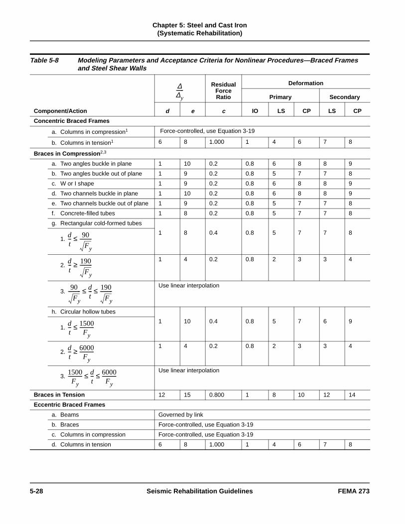
Chapter 5: Steel and Cast Iron
(Systematic Rehabilitation)
Table 5-8 Modeling Parameters and Acceptance Criteria for Nonlinear Procedures—Braced Frames and Steel Shear Walls
Component/Action
ResidualForceRatio
Deformation
Primary Secondary
d e c IO LS CP LS CP
Concentric Braced Frames
a. Columns in compression1 Force-controlled, use Equation 3-19
b. Columns in tension1 6 8 1.000 1 4 6 7 8
Braces in Compression 2,3
a. Two angles buckle in plane 1 10 0.2 0.8 6 8 8 9
b. Two angles buckle out of plane 1 9 0.2 0.8 5 7 7 8
c. W or I shape 1 9 0.2 0.8 6 8 8 9
d. Two channels buckle in plane 1 10 0.2 0.8 6 8 8 9
e. Two channels buckle out of plane 1 9 0.2 0.8 5 7 7 8
f. Concrete-filled tubes 1 8 0.2 0.8 5 7 7 8
g. Rectangular cold-formed tubes
1 8 0.4 0.8 5 7 7 81.
2. 1 4 0.2 0.8 2 3 3 4
3. Use linear interpolation
h. Circular hollow tubes
1 10 0.4 0.8 5 7 6 91.
2. 1 4 0.2 0.8 2 3 3 4
3. Use linear interpolation
Braces in Tension 12 15 0.800 1 8 10 12 14
Eccentric Braced Frames
a. Beams Governed by link
b. Braces Force-controlled, use Equation 3-19
c. Columns in compression Force-controlled, use Equation 3-19
d. Columns in tension 6 8 1.000 1 4 6 7 8
∆∆y------
dt--- 90
Fy
----------≤
dt--- 190
Fy
----------≥
90
Fy
---------- dt---≤ 190
Fy
----------≤
dt--- 1500
Fy------------≤
dt--- 6000
Fy------------≥
1500Fy
------------ dt---≤ 6000
Fy------------≤
5-28 Seismic Rehabilitation Guidelines FEMA 273

Chapter 5: Steel and Cast Iron
(Systematic Rehabilitation)
PR el
5.5.2.4 Rehabilitation Measures for Concentric Braced Frames
Provisions for moment frames may be applicable to braced frames. Braces that are insufficient in strength and/or ductility may be replaced or modified. Insufficient connections may also be modified. Columns may be encased in concrete to improve their performance. For further guidance, see Section 5.4.2.4 and the Commentary.
5.5.3 Eccentric Braced Frames (EBF)
5.5.3.1 General
For an EBF, the action lines of the braces do not intersect at the action line of the beam. The distance between the brace action lines where they intersect the beam action line is the eccentricity, e. The beam segment between these points is the link beam. The strength of the frame is governed by the strength of the link beam.
5.5.3.2 Stiffness for Analysis
A. Linear Static and Dynamic Procedures
The elastic stiffness of beams, columns, braces, andconnections are the same as those used for FR and moment frames and CBF. The load-deformation modfor a link beam must include shear deformation and flexural deformation.
The elastic stiffness of the link beam, Ke, is
(5-26)
where
(5-27)
Link Beam 3
a.416 18 0.80 1.5 12 15 15 17
b.Same as for beam in FR moment frame (see Table 5-4)
c.Use linear interpolation
Steel Shear Walls 5 15 17 .07 1.5 11 14 14 16
1. Columns in moment or braced frames need only be designed for the maximum force that can be delivered.
2. ∆c is the axial deformation at expected buckling load.
3. Deformation is rotation angle between link and beam outside link or column. Assume ∆y is 0.01 radians for short links.
4. Link beams with three or more web stiffeners. If no stiffeners, use half of these values. For one or two stiffeners, interpolate.
5. Applicable if stiffeners are provided to prevent shear buckling.
Table 5-8 Modeling Parameters and Acceptance Criteria for Nonlinear Procedures—Braced Frames and Steel Shear Walls (continued)
Component/Action
ResidualForceRatio
Deformation
Primary Secondary
d e c IO LS CP LS CP
∆∆y------
2MCE
eVCE-------------- 1.6≤
2MCE
eVCE--------------- 2.6≥
1.62MCE
eVCE--------------- 2.6≤ ≤
Ke
KsKb
Ks Kb+-------------------=
Ks
GAw
e-----------=
FEMA 273 Seismic Rehabilitation Guidelines 5-29

Chapter 5: Steel and Cast Iron
(Systematic Rehabilitation)
r
in
C
he
e st
me
ay eir
ks d be
th .
n to r
and
(5-28)
where
The strength of the link beam may be governed by shear, flexure, or the combination of these.
If
(5-29)
where
If
(5-30)
If , use linear interpolation
between Equations 5-29 and 5-30.
The yield deformation is the link rotation as given by
(5-31)
B. Nonlinear Static Procedure
The NSP requires modeling of the complete nonlineaload-deformation relation to failure for each component. This may be based on experiment, or rational analysis verified by experiment. In lieu of these, the load versus deformation relationship givenFigure 5-1 and Table 5-8 may be used. QCE and θy are calculated in accordance with provisions given in AIS(1994a) or by rational analysis.
The nonlinear models used for beams, columns, andconnections for FR and PR moment frames, and for tbraces for a CBF, may be used.
C. Nonlinear Dynamic Procedure
The strength and deformation criteria require that theload and resistance relationships given in Equations 3-18 and 3-19 in Chapter 3 be satisfied. Thcomplete hysteretic behavior of each component mube modeled for this procedure. Guidelines for this aregiven in the Commentary.
5.5.3.3 Strength and Deformation Acceptance Criteria
A. Linear Static and Dynamic Procedures
The modeling assumptions given for a CBF are the saas those for an EBF. Values for QCE and θy are given in Section 5.5.3.2 and m values are given in Table 5-7. Thestrength and deformation capacities of the link beam mbe governed by shear strength, flexural strength, or thinteraction. The values of QCE and θy are the same as those used in the LSP as given in Section 5.5.3.2A. Linand beams are deformation-controlled components anmust satisfy Equation 3-18. Columns and braces are toconsidered force-controlled members and must satisfyEquation 3-19.
The requirements for link stiffeners, link-to-column connections, lateral supports of the link, the diagonal brace and beam outside the link, and beam-to-columnconnections given in AISC (1994a) must be met. The brace should be able to carry 1.25 times the link strengto ensure link yielding without brace or column bucklingIf this is not satisfied for existing buildings, the design professional shall make extra efforts to verify that the expected link strength will be reached before brace orcolumn buckling. This may require additional inspectioand material testing. Where the link beam is attached the column flange with full-pen welds, the provisions fothese connections is the same as for FR frame full-pen
Aw = (db – 2tf) tw, in.2
e = Length of link beam, in.
G = Shear modulus, k/in.2
Ke = Stiffness of the link beam, k/in.
Kb = Flexural stiffness, kip/in.
Ks = Shear stiffness, kip/in.
MCE = Expected moment, kip/in.
Kb
12EIb
e3
---------------=
e1.6MCE
VCE-------------------≤
QCE VCE 0.6FyetwAw= =
e2.6MCE
VCE------------------->
QCE VCE 2MCE
e-----------= =
1.6MCE
VCE------------------- e
2.6MCE
VCE-------------------≤ ≤
θy
QCE
Kee----------=
5-30 Seismic Rehabilitation Guidelines FEMA 273

Chapter 5: Steel and Cast Iron
(Systematic Rehabilitation)
ll al
or
is,
t
el
connections. The columns of an EBF are force-controlled members. The maximum force deliverable to a column should be calculated from the maximum brace forces equal to 1.25 times the calculated strength of the brace.
B. Nonlinear Static Procedure
The NSP requirements for an EBF are the same as those for a CBF. Modeling of the nonlinear load deformation of the link beam should be based on experiment, or rational analysis verified by experiment. In lieu of these, the conservative approximate behavior depicted in Figure 5-1 may be used. Values for QCE and θy are the same as those used for the LSP. Deformation limits are given in Table 5-8.
C. Nonlinear Dynamic Procedure
The complete hysteretic behavior of each component must be properly modeled. This behavior must be verified by experiment. This procedure is not recommended in most cases.
5.5.3.4 Rehabilitation Measures for Eccentric Braced Frames
Many of the beams, columns, and braces may be rehabilitated using procedures given for moment frames and CBFs. Cover plates and/or stiffeners may be used for these components. The strength of the link beam may be increased by adding cover plates to the beam flange(s), adding doubler plates or stiffeners to the web, or changing the brace configuration.
5.6 Steel Plate Walls
5.6.1 General
A steel plate wall develops its seismic resistance through shear stress in the plate wall. In essence, it is a steel shear wall. A solid steel plate, with or preferably without perforations, fills an entire bay between columns and beams. The steel plate is welded to the columns on each side and to the beams above and below. Although these are not common, they have been used to rehabilitate a few essential structures where immediate occupancy and operation of a facility is mandatory after a large earthquake. These walls work in conjunction with other existing elements to resist seismic load. However, due to their stiffness, they attract much of the seismic shear. It is essential that the new load paths be carefully established.
5.6.2 Stiffness for Analysis
5.6.2.1 Linear Static and Dynamic Procedures
The most appropriate way to analyze a steel plate wais to use a plane stress finite element model with thebeams and columns as boundary elements. The globstiffness of the wall can be calculated. The modeling can be similar to that used for a reinforced concrete shear wall. A simple approximate stiffness Kw for the wall is
(5-32)
where
Other approximations of the wall stiffness based on principles of mechanics are acceptable.
5.6.2.2 Nonlinear Static Procedure
The elastic part of the load-deformation relationship fthe wall is given in Section 5.6.2.1. The yield load, QCE, is given in the next section. The complete nonlinear load-deformation relationship should be based on experiment or rational analysis. In lieu of ththe approximate simplified behavior may be modeledusing Figure 5-1 and Table 5-8.
5.6.2.3 Nonlinear Dynamic Procedure
The complete hysteretic behavior of each componenmust be properly modeled. This behavior must be verified by experiment. This procedure is not recommended in most cases.
5.6.3 Strength and Deformation Acceptance Criteria
5.6.3.1 Linear Static and Dynamic Procedures
The strength and deformation acceptance criteria forthese methods require that the load and resistance relationships given in Equations 3-18 and 3-19 in Chapter 3 be satisfied. The design strength of the ste
G = Shear modulus of steel, ksia = Clear width of wall between columns, in.h = Clear height of wall between beams, in.tw = Thickness of plate wall, in.
Kw
Ga twh
---------------=
FEMA 273 Seismic Rehabilitation Guidelines 5-31

Chapter 5: Steel and Cast Iron
(Systematic Rehabilitation)
r
ces
ill er
ges int
e
fs
ck ets, ,
st to re
e nts
wall shall be determined using the appropriate equations in Part 6 of AISC (1994a). The wall can be assumed to be like the web of a plate girder. Design restrictions for plate girder webs given in AISC (1994a), particularly those related to stiffener spacing, must be followed. Stiffeners should be spaced such that buckling of the wall does not occur. In this case
(5-33)
In lieu of stiffeners, the steel wall may be encased in concrete. If buckling is not prevented, equations for VCE given in AISC (1994a) for plate girders may be used. The m values for steel walls are given in Table 5-7. A steel shear wall is a deformation-controlled component.
5.6.3.2 Nonlinear Static Procedure
The NSP requires modeling of the complete load-deformation behavior to failure. This may be based on experiment or rational analysis. In lieu of these, the conservative approximate behavior depicted in Figure 5-1 may be used, along with parameters given in Table 5-8. The equation for QCE is Equation 5-33. The yield deformation is
(5-34)
5.6.3.3 Nonlinear Dynamic Procedure
The complete hysteretic behavior of each component must be properly modeled. This behavior must be verified by experiment. This procedure is not recommended in most cases.
5.6.4 Rehabilitation Measures
This is not an issue because steel walls in existing construction are rare.
5.7 Steel Frames with InfillsIt is common for older existing steel frame buildings to have complete or partial infill walls of reinforced concrete or masonry. Due to the high wall stiffness relative to the frame stiffness, the infill walls will attract most of the seismic shear. In many cases, because these walls are unreinforced or lightly reinforced, their strength and ductility may be inadequate.
The engineering properties and acceptance criteria fothe infill walls are presented in Chapter 6 for concreteand Chapter 7 for masonry. The walls may be considered to carry all of the seismic shear in these elements until complete failure of the walls has occurred. After that, the steel frames will resist the seismic forces. Before the loss of the wall, the steel frame adds confining pressure to the wall and enhanits resistance. However, the actual effective forces onthe steel frame components are probably minimal. Asthe frame components begin to develop force they wdeform; however, the concrete or masonry on the othside is stiffer so it picks up the load.
The analysis of the component should be done in staand carried through each performance goal. At the powhere the infill has been deemed to fail—as given in Chapter 6 or Chapter 7—the wall should be removedfrom the analytical model and the analysis resumed with only the bare steel frame in place. At this point, thengineering properties and acceptance criteria for themoment frame given above in Section 5.4 are applicable.
5.8 Diaphragms
5.8.1 Bare Metal Deck Diaphragms
5.8.1.1 General
Bare metal deck diaphragms are usually used for rooof buildings where there are very light gravity loads other than support of roofing materials. The metal deunits are often composed of gage thickness steel shefrom 22 gage down to 14 gage, two to three feet wideand formed in a repeating pattern with ridges and valleys. Rib depths vary from 1-1/2 to 3 inches in mocases. Decking units are attached to each other and the structural steel supports by welds or, in some morecent applications, by mechanical fasteners. In largeroof structures, these roofs may have supplementarydiagonal bracing. (See the description of horizontal steel bracing in Section 5.8.4.)
Chord and collector elements in these diaphragms arconsidered to be composed of the steel frame elemeattached to the diaphragm. Load transfer to frame elements that act as chords or collectors in modern frames is through shear connectors, puddle welds, screws, or shot pins.
QCE VCE 0.6Fyeatw = =
θy
QCE
Kw----------=
5-32 Seismic Rehabilitation Guidelines FEMA 273

Chapter 5: Steel and Cast Iron
(Systematic Rehabilitation)
n e
to ct. d
e
d he
st m e S
g
t
5.8.1.2 Stiffness for Analysis
A. Linear Static Procedure
The distribution of forces for existing diaphragms is based on flexible diaphragm assumption, with diaphragms acting as simply supported between the stiff vertical lateral-force-resisting elements. Flexibility factors for various types of metal decks are available from manufacturers’ catalogs. In systems for which values are not available, values can be established by interpolating between the most representative systems for which values are available. Flexibility can also be calculated using the Steel Deck Institute Diaphragm Design Manual (Section 3). The analysis should verify that the diaphragm strength is not exceeded for the elastic assumption to hold.
All criteria for existing diaphragms mentioned above apply to stiffened or strengthened diaphragms. Interaction of new and existing elements of strengthened diaphragms must be considered to ensure stiffness compatibility. Load transfer mechanisms between new and existing diaphragm elements must be considered.
Analyses should verify that diaphragm strength is not exceeded, so that elastic assumptions are still valid.
B. Nonlinear Static Procedure
Inelastic properties of diaphragms are usually not included in inelastic seismic analyses.
More flexible diaphragms, such as bare metal deck or deck-formed slabs with long spans between lateral-force-resisting elements, could be subject to inelastic action. Procedures for developing models for inelastic response of wood diaphragms in unreinforced masonry (URM) buildings could be used as the basis for an inelastic model of a bare metal deck diaphragm condition. A strain-hardening modulus of 3% could be used in the post-elastic region. If the weak link of the diaphragm is connection failure, then the element nonlinearity cannot be incorporated into the model.
5.8.1.3 Strength and Deformation Acceptance Criteria
Member capacities of steel deck diaphragms are given in International Conference of Building Officials (ICBO) reports, in manufacturers’ literature, or in the publications of the Steel Deck Institute (SDI). (See the references in Section 5.12 and Commentary Section C5.12.) Where allowable stresses are given,
these may be multiplied by 2.0 in lieu of information provided by the manufacturer or other knowledgeablesources. If bare deck capacity is controlled by connections to frame members or panel buckling, theinelastic action and ductility are limited. Therefore, thdeck should be considered to be a force-controlled member.
In many cases, diaphragm failure would not be a life safety consideration unless it led to a loss of bearingsupport or anchorage. Goals for higher performance would limit the amount of damage to the connections insure that the load transfer mechanism was still intaDeformations should be limited to below the thresholof deflections that cause damage to other elements (either structural or nonstructural) at specified Performance Levels.
The m value for shear yielding, or panel or plate buckling is 1, 2, or 3 for the IO, LS, or CP PerformancLevels, respectively. Weld and connector failure is force-controlled.
The SDI calculations procedure should be used for strengths, or ICBO values with a multiplier may be useto bring allowable values to expected strength levels.Specific references are given in Section 5.12 and in tCommentary, Section C5.12.
Connections between metal decks and steel framing commonly use puddle welds. Connection capacity mube checked for the ability to transfer the total diaphragreaction into the steel framing. Connection capacitiesare provided in ICBO reports, manufacturers’ data, thSDI Manual, or the Welding Code for Sheet Steel, AWD1.3. Other attachment systems, such as clips, are sometimes used.
5.8.1.4 Rehabilitation Measures
See the Commentary.
5.8.2 Metal Deck Diaphragms with Structural Concrete Topping
5.8.2.1 General
Metal deck diaphragms with structural concrete toppinare frequently used on floors and roofs of buildings where there are typical floor gravity loads. The metaldeck may be either a composite deck, which has indentations, or a noncomposite form deck. In both types of deck, the slab and deck act together to resis
FEMA 273 Seismic Rehabilitation Guidelines 5-33

Chapter 5: Steel and Cast Iron
(Systematic Rehabilitation)
n
d
d
se as or k nt
gs,
at
or t
f
diaphragm loads. The concrete fill may be either normal or lightweight concrete, with reinforcing composed of wire mesh or small-diameter reinforcing steel. Additional slab reinforcing may be added at areas of high stress. The metal deck units are composed of gage thickness steel sheets, two to three feet wide, and are formed in a repeating pattern with ridges and valleys. Decking units are attached to each other and to structural steel supports by welds or, in some more recent applications, by mechanical fasteners. Concrete diaphragms in which the slab was formed and the beams are encased in concrete for fire protection may be considered to be similar to topped metal deck diaphragms.
Concrete has structural properties that significantly add to diaphragm stiffness and strength. Concrete reinforcing ranges from light mesh reinforcement to a regular grid of small reinforcing bars (#3 or #4). Metal decking is typically composed of corrugated sheet steel from 22 ga. down to 14 ga. Rib depths vary from 1-1/2 to 3 inches in most cases. Attachment of the metal deck to the steel frame is usually accomplished using puddle welds at one to two feet on center. For composite behavior, shear studs are welded to the frame before the concrete is cast.
Chord and collector elements in these diaphragms are considered to be composed of the steel frame elements attached to the diaphragm. Load transfer to frame elements that act as chords or collectors in modern frames is usually through puddle welds or headed studs. In older construction where the frame is encased for fire protection, load transfer is made through bond.
5.8.2.2 Stiffness for Analysis
A. Linear Static Procedure
For existing diaphragms, the distribution of forces may be based on a rigid diaphragm assumption if the diaphragm span-to-depth ratio is not greater than five to one. For greater ratios, justify with analysis. Diaphragm flexibility should be included in cases with larger spans and/or plan irregularities by three-dimensional analysis procedures and shell finite elements for the diaphragms. Diaphragm stiffness can be calculated using the SDI Design Manual, manufacturers’ catalogs, or with a representative concrete thickness.
All procedures for existing diaphragms noted above apply to strengthened diaphragms as well. Interaction of new and existing elements of strengthened diaphragms
(stiffness compatibility) must be considered. Load transfer mechanisms between new and existing diaphragm components may need to be considered idetermining the flexibility of the diaphragm.
All procedures for existing diaphragms noted above apply to new diaphragms. Interaction of new diaphragms with the existing frames must be considered. Load transfer mechanisms between newdiaphragm components and existing frames may neeto be considered in determining the flexibility of the diaphragm.
For all diaphragms, the analyses must verify that the diaphragm strength is not exceeded, so that elastic assumptions are still valid.
B. Nonlinear Static Procedure
Inelastic properties of diaphragms are usually not included in inelastic seismic analyses, but could be ifthe connections are adequate. More flexible diaphragms—such as bare metal deck or deck-formeslabs with long spans between lateral-force-resistingelements—could be subject to inelastic action. Procedures for developing models for inelastic responof wood diaphragms in URM buildings could be used the basis for an inelastic model of a bare metal deck long span composite diaphragm condition. If the wealink of the diaphragm is connection failure, the elemenonlinearity cannot be incorporated into the model.
5.8.2.3 Strength and Deformation Acceptance Criteria
Member capacities of steel deck diaphragms with structural concrete are given in manufacturers’ cataloICBO reports, or the SDI Manual. If composite deck capacity is controlled by shear connectors, inelastic action and ductility are limited. It would be expected that there would be little or no inelastic action in steeldeck/concrete diaphragms, except in long span conditions; however, perimeter transfer mechanisms and collector forces must be considered to be sure ththis is the case.
In many cases, diaphragm failure would not be a life safety consideration unless it led to a loss of bearingsupport or anchorage. Goals for higher performance would limit the amount of damage to the connections cracking in concrete-filled slabs in order to ensure thathe load transfer mechanism was still intact. Deformations should be limited below the threshold o
5-34 Seismic Rehabilitation Guidelines FEMA 273

Chapter 5: Steel and Cast Iron
(Systematic Rehabilitation)
is - a
d
lly e es r re
d e 2
9/l d
teel
f of n m ts
s ay
al
deflections that cause damage to other elements (either structural or nonstructural) at specified Performance Levels.
Connection failure is force-limited, so Equation 3-19 must be used. Shear failure of the deck requires cracking of the concrete and/or tearing of the metal deck, so the m values for IO, LS, and CP Performance Levels are 1, 2, and 3, respectively. See Section 5.8.6.3 for acceptance criteria for collectors.
SDI calculation procedures should be used for strengths, or ICBO values with a multiplier of 2.0 should be used to bring allowable values to a strength level. The deck will be considered elastic in most analyses.
Connector capacity must be checked for the ability to transfer the total diaphragm reaction into the supporting steel framing. This load transfer can be achieved by puddle welds and/or headed studs. For the connection of the metal deck to steel framing, puddle welds to beams are most common. Connector capacities are provided in ICBO reports, manufacturers’ data, the SDI Manual, or the Welding Code for Sheet Steel, AWS D1.3. Shear studs replace puddle welds to beams where they are required for composite action with supporting steel beams.
Headed studs are most commonly used for connection of the concrete slab to steel framing. Connector capacities can be found using the AISC Manual of Steel Construction, UBC, or manufacturers’ catalogs. When steel beams are designed to act compositely with the slab, shear connectors must have the capacity to transfer both diaphragm shears and composite beam shears. In older structures where the beams are encased in concrete, load transfer may be provided through bond between the steel and concrete.
5.8.2.4 Rehabilitation Measures
See the Commentary.
5.8.3 Metal Deck Diaphragms with Nonstructural Concrete Topping
5.8.3.1 General
Metal deck diaphragms with nonstructural concrete fill are typically used on roofs of buildings where there are very small gravity loads. The concrete fill, such as very lightweight insulating concrete (e.g., vermiculite), does
not have usable structural properties. If the concrete reinforced, reinforcing consists of wire mesh or smalldiameter reinforcing steel. Typically, the metal deck isform deck or roof decks, so the only attachment between the concrete and metal deck is through bonand friction. The concrete fill is not designed to act compositely with the metal deck and has no positive structural attachment. The metal deck units are typicacomposed of gage thickness steel sheets, two to threfeet wide, and formed in a repeating pattern with ridgand valleys. Decking units are attached to each otheand structural steel supports by welds or, in some morecent applications, by mechanical fasteners.
Consideration of any composite action must be donewith caution, after extensive investigation of field conditions. Material properties, force transfer mechanisms, and other similar factors must be verifiein order to include such composite action. Typically, thdecks are composed of corrugated sheet steel from 2gage down to 14 gage, and the rib depths vary from 16 to 3 inches in most cases. Attachment to the steeframe is usually through puddle welds, typically spaceat one to two feet on center. Chord and collector elements in these diaphragms are composed of the sframe elements attached to the diaphragm.
5.8.3.2 Stiffness for Analysis
A. Linear Static Procedure
The potential for composite action and modification oload distribution must be considered. Flexibility of thediaphragm will depend on the strength and thicknessthe topping. It may be necessary to bound the solutioin some cases, using both rigid and flexible diaphragassumptions. Interaction of new and existing elemenof strengthened diaphragms (stiffness compatibility) must be considered, and the load transfer mechanismbetween the new and existing diaphragm elements mneed to be considered in determining the flexibility ofthe diaphragm. Similarly, the interaction of new diaphragms with existing frames must be carefully considered, as well as the load transfer mechanismsbetween them. Finally, the analyses must verify that diaphragm strength is not exceeded, so elastic assumptions are still valid.
B. Nonlinear Static Procedure
Inelastic properties of diaphragms are usually not included in inelastic seismic analyses. When nonstructural topping is present its capacity must be verified. More flexible diaphragms, such as bare met
FEMA 273 Seismic Rehabilitation Guidelines 5-35

Chapter 5: Steel and Cast Iron
(Systematic Rehabilitation)
d th
n el
. n
e nt.
e e
, ll,
or
, or
r lar
nd
e es ld d l
deck or decks with inadequate nonstructural topping, could be subject to inelastic action. Procedures for developing models for inelastic response of wood diaphragms in URM buildings could be used as the basis for an inelastic model of a bare metal deck diaphragm condition. If a weak link of the diaphragm is connection failure, then the element nonlinearity cannot be incorporated into the model.
5.8.3.3 Strength and Deformation Acceptance Criteria
A. Linear Static Procedure
Capacities of steel deck diaphragms with nonstructural topping are provided by ICBO reports, by manufacturers, or in general by the SDI Manual. When the connection failure governs, or topping lacks adequate strength, inelastic action and ductility are limited. As a limiting case, the diaphragm shear may be computed using only the bare deck (see Section 5.8.1 for bare decks). Generally, there should be little or no inelastic action in the diaphragms, provided the connections to the framing members are adequate.
In many cases, diaphragm failure would not be a life safety consideration unless it led to a loss of bearing support or anchorage. Goals for higher Performance Levels would limit the amount of damage to the connections or cracking in concrete filled slabs, to ensure that the load transfer mechanism was still intact. Deformations should be limited below the threshold of deflections that cause damage to other elements (either structural or nonstructural) at specified performance levels.
Connection failure is force-limited, so Equation 3-19 must be used. Shear failure of the deck requires concrete cracking and/or tearing of the metal deck, so m values for IO, LS, and CP are 1, 2, and 3, respectively. Panel buckling or plate buckling have m values of 1, 2, and 3 for IO, LS, and CP. SDI calculation procedures should be used for strengths, or ICBO values with a multiplier to bring allowable values to strength levels.
5.8.3.4 Rehabilitation Measures
See the Commentary.
5.8.4 Horizontal Steel Bracing (Steel Truss Diaphragms)
5.8.4.1 General
Horizontal steel bracing (steel truss diaphragms) maybe used in conjunction with bare metal deck roofs anin conditions where diaphragm stiffness and/or strengis inadequate to transfer shear forces. Steel truss diaphragm elements are typically found in conjunctiowith vertical framing systems that are of structural steframing. Steel trusses are more common in long spansituations, such as special roof structures for arenas,exposition halls, auditoriums, and industrial buildingsDiaphragms with a large span-to-depth ratio may oftebe stiffened by the addition of steel trusses. The addition of steel trusses for diaphragms identified to bdeficient may provide a proper method of enhanceme
Horizontal steel bracing (steel truss diaphragms) maybe made up of any of the various structural shapes. Often, the truss chord elements consist of wide flangshapes that also function as floor beams to support thgravity loads of the floor. For lightly loaded conditionssuch as industrial metal deck roofs without concrete fithe diagonal members may consist of threaded rod elements, which are assumed to act only in tension. Fsteel truss diaphragms with large loads, diagonal elements may consist of wide flange members, tubesother structural elements that will act in both tension and compression. Truss element connections are generally concentric, to provide the maximum lateral stiffness and ensure that the truss members act undepure axial load. These connections are generally simito those of gravity-load-resisting trusses. Where concrete fill is provided over the metal decking, consideration of relative rigidities between the truss aconcrete systems may be necessary.
5.8.4.2 Stiffness for Analysis
A. Linear Static Procedure
Existing truss diaphragm systems are modeled as horizontal truss elements (similar to braced steel frames) where axial stiffness controls the deflections.Joints are often taken as pinned. Where joints providthe ability for moment resistance or where eccentricitiare introduced at the connections, joint rigidities shoube considered. A combination of stiffness with that ofconcrete fill over metal decking may be necessary insome instances. Flexibility of truss diaphragms shoulbe considered in distribution of lateral loads to verticaelements.
5-36 Seismic Rehabilitation Guidelines FEMA 273

Chapter 5: Steel and Cast Iron
(Systematic Rehabilitation)
e
ad at e of
n
ist
g.
a
nts
f re
The procedures for existing diaphragms provided above apply to strengthened truss diaphragms. Interaction of new and existing elements of strengthened diaphragm systems (stiffness compatibility) must be considered in cases where steel trusses are added as part of a seismic upgrade. Load transfer mechanisms between new and existing diaphragm elements must be considered in determining the flexibility of the strengthened diaphragm.
The procedures for existing truss diaphragms mentioned above also apply to new diaphragms. Interaction of new truss diaphragms with existing frames must be considered. Load transfer mechanisms between new diaphragm elements and existing frames may need to be considered in determining the flexibility of the diaphragm/frame system.
For modeling assumptions and limitations, see the preceding comments related to truss joint modeling, force transfer, and interaction between diaphragm elements. Analyses are also needed to verify that elastic diaphragm response assumptions are still valid.
Acceptance criteria for the components of a truss diaphragm are the same as for a CBF.
B. Nonlinear Static Procedure
Inelastic properties of truss diaphragms are usually not included in inelastic seismic analyses. In the case of truss diaphragms, inelastic models similar to those of braced steel frames may be appropriate. Inelastic deformation limits of truss diaphragms may be different from those prescribed for braced steel frames (e.g., more consistent with that of a concrete-topped diaphragm).
5.8.4.3 Strength and Deformation Acceptance Criteria
Member capacities of truss diaphragm members may be calculated in a manner similar to those for braced steel frame members. It may be necessary to include gravity force effects in the calculations for some members of these trusses. Lateral support conditions provided by metal deck, with or without concrete fill, must be properly considered. Force transfer mechanisms between various members of the truss at the connections, and between trusses and frame elements, must be considered to verify the completion of the load path.
In many cases, diaphragm distress would not be a lifsafety consideration unless it led to a loss of bearingsupport or anchorage. Goals for higher PerformanceLevels would limit the amount of damage to the connections or bracing elements, to insure that the lotransfer mechanism was still complete. Deformationsshould be limited below the threshold of deflections thcause damage to other elements (either structural ornonstructural) at specified Performance Levels. Thesvalues must be established in conjunction with thosebraced steel frames.
The m values to be used are half of those for components of a CBF as given in Table 5-7.
A. Nonlinear Static Procedure
Procedures similar to those used for a CBF should beused, but deformation limits shall be half of those givefor CBFs in Table 5-8.
5.8.4.4 Rehabilitation Measures
See the Commentary.
5.8.5 Archaic Diaphragms
5.8.5.1 General
Archaic diaphragms in steel buildings generally consof shallow brick arches that span between steel floorbeams, with the arches packed tightly between the beams to provide the necessary resistance to thrust forces. Archaic steel diaphragm elements are almostalways found in older steel buildings in conjunction with vertical systems that are of structural steel framinThe brick arches were typically covered with a very low-strength concrete fill, usually unreinforced. In many instances, various archaic diaphragm systemswere patented by contractors.
5.8.5.2 Stiffness for Analysis
A. Linear Static Procedure
Existing archaic diaphragm systems are modeled as horizontal diaphragm with equivalent thickness of arches and concrete fill. Development of truss elemebetween steel beams and compression elements of arches could also be considered. Flexibility of archaicdiaphragms should be considered in the distribution olateral loads to vertical elements, especially if spans alarge.
FEMA 273 Seismic Rehabilitation Guidelines 5-37

Chapter 5: Steel and Cast Iron
(Systematic Rehabilitation)
rd
ng he en r d
he ,
n
o
ge .
rs
g s
All preceding comments for existing diaphragms apply for archaic diaphragms. Interaction of new and existing elements of strengthened elements (stiffness compatibility) must be considered in cases where steel trusses are added as part of a seismic upgrade. Load transfer mechanisms between new and existing diaphragm elements must be considered in determining the flexibility of the strengthened diaphragm.
For modeling assumptions and limitations, see the preceding comments related to force transfer, and interaction between diaphragm elements. Analyses are required to verify that elastic diaphragm response assumptions are valid.
B. Nonlinear Static Procedure
Inelastic properties of archaic diaphragms should be chosen with caution for seismic analyses. For the case of archaic diaphragms, inelastic models similar to those of archaic timber diaphragms in unreinforced masonry buildings may be appropriate. Inelastic deformation limits of archaic diaphragms should be lower than those prescribed for a concrete-filled diaphragm.
5.8.5.3 Strength and Deformation Acceptance Criteria
Member capacities of archaic diaphragm components can be calculated assuming little or no tension capacity except for the steel beam members. Gravity force effects must be included in the calculations for all components of these diaphragms. Force transfer mechanisms between various members and between frame elements must be considered to verify the completion of the load path.
In many cases, diaphragm distress could result in life safety considerations, due to possible loss of bearing support for the elements of the arches. Goals for higher performance would limit the amount of diagonal tension stresses, to insure that the load transfer mechanism was still complete. Deformations should be limited below the threshold of deflections that cause damage to other elements (either structural or nonstructural) at specified Performance Levels. These values must be established in conjunction with those for steel frames. Archaic diaphragm components should be considered as force-limited, so Equation 3-19 must be used.
5.8.5.4 Rehabilitation Measures
See the Commentary.
5.8.6 Chord and Collector Elements
5.8.6.1 General
Chords and collectors for all the previously describeddiaphragms typically consist of the steel framing thatsupports the diaphragm. When structural concrete ispresent, additional slab reinforcing may act as the choor collector for tensile loads, while the slab carries chord or collector compression. When the steel framiacts as a chord or collector, it is typically attached to tdeck with spot welds or by mechanical fasteners. Whreinforcing acts as the chord or collector, load transfeoccurs through bond between the reinforcing bars anthe concrete.
5.8.6.2 Stiffness for Analysis
Modeling assumptions similar to those for equivalentframe members should be used.
5.8.6.3 Strength and Deformation Acceptance Criteria
Capacities of chords and collectors are provided by tAISC LRFD Specifications (1994a) and ACI-318 (ACI1995; see Chapter 6 for the citation) design guides. Inelastic action may occur, depending on the configuration of the diaphragm. It is desirable to desigchord and collector components for a force that will develop yielding or ductile failure in either the diaphragm or vertical lateral-force-resisting system, sthat the chords and collectors are not the weak link inthe load path. In some cases, failure of chord and collector components may result in a life safety consideration when beams act as the chords or collectors and vertical support is compromised. Goalsfor higher performance would limit stresses and damain chords and collectors, keeping the load path intact
In buildings where the steel framing members that support the diaphragm act as collectors, the steel components may be alternately in tension and compression. If all connections to the diaphragm aresufficient, the diaphragm will prevent buckling of the chord member so values of m equal to 1, 6, and 8 may be used for IO, LS, and CP, respectively. If the diaphragm provides only limited support against buckling of the chord or collector, values of m equal to 1, 2, and 3 should be used. Where chords or collectocarry gravity loads along with seismic loads, they should be checked as members with combined loadinusing Equations 5-10 and 5-11. Welds and connector
5-38 Seismic Rehabilitation Guidelines FEMA 273

Chapter 5: Steel and Cast Iron
(Systematic Rehabilitation)
in
he 0.
to
a
m.
f .
s t e re
joining the diaphragms to the collectors should be considered to be force-controlled.
5.8.6.4 Rehabilitation Measures
See the Commentary.
5.9 Steel Pile Foundations
5.9.1 General
Steel piles are one of the most common components for building foundations. Wide flange shapes (H piles) or structural tubes, with and without concrete infills, are the most commonly used shapes. Piles are usually driven in groups. A reinforced concrete pile cap is then cast over each group, and a steel column with a base plate is attached to the pile cap with anchor bolts.
The piles provide strength and stiffness to the foundation in one of two ways. Where very strong soil or rock lies at not too great a distance below the building site, the pile forces are transferred directly to the soil or rock at the bearing surface. Where this condition is not met, the piles are designed to transfer their load to the soil through friction. The design of the entire foundation is covered in Chapter 4 of these Guidelines. The design of the steel piles is covered in the following subsections.
5.9.2 Stiffness for Analysis
If the pile cap is below grade, the foundation attains much of its stiffness from the pile cap bearing against the soil. Equivalent soil springs may be derived as discussed in Chapter 4. The piles may also provide significant stiffness through bending and bearing against the soil. The effective pile contribution to stiffness is decreased if the piles are closely spaced; this group effect must be taken into account when calculating foundation and strength. For a more detailed description, see the Commentary, Section C5.9.2, and Chapter 4 of these Guidelines.
5.9.3 Strength and Deformation Acceptance Criteria
Buckling of steel piles is not a concern, since the soil provides lateral support. The moments in the piles may be calculated in one of two ways. The first is an elastic method that requires finding the effective point of fixity; the pile is then designed as a cantilever column. The second, a nonlinear method, requires a computer
program that is available at no cost. Details are giventhe Commentary, Section C5.9.2.
Once the axial force and maximum bending momentsare known, the pile strength acceptance criteria are tsame as for a steel column, as given in Equation 5-1The expected axial and flexural strengths in Equation 5-10 are computed for an unbraced length equal to zero. Note that Equation 5-11 does not applysteel piles. Exceptions to these criteria, where liquefaction is a concern, are discussed in the Commentary, Section C5.9.2.
5.9.4 Rehabilitation Measures for Steel Pile Foundations
Rehabilitation of the pile cap is covered in Chapter 6.Chapter 4 covers general criteria for the rehabilitationof the foundation element. In most cases, it is not possible to rehabilitate the existing piles. Increased stiffness and strength may be gained by driving additional piles near existing groups and then addingnew pile cap. Monolithic behavior can be gained by connecting the new and old pile caps with epoxied dowels, or other means.
5.10 DefinitionsBeam: A structural member whose primary functionis to carry loads transverse to its longitudinal axis; usually a horizontal member in a seismic frame syste
Braced frame: An essentially vertical truss system oconcentric or eccentric type that resists lateral forces
Concentric braced frame (CBF): A braced frame in which the members are subjected primarily to axial forces.
Connection: A link between components or elementthat transmits actions from one component or elemento another component or element. Categorized by typof action (moment, shear, or axial), connection links afrequently nonductile.
Continuity plates: Column stiffeners at the top and bottom of the panel zone.
Diagonal bracing: Inclined structural members carrying primarily axial load, employed to enable a structural frame to act as a truss to resist horizontal loads.
FEMA 273 Seismic Rehabilitation Guidelines 5-39

Chapter 5: Steel and Cast Iron
(Systematic Rehabilitation)
e in
d s
nts
e d
s as
r
e
Dual system: A structural system included in buildings with the following features:
• An essentially complete space frame provides support for gravity loads.
• Resistance to lateral load is provided by concrete or steel shear walls, steel eccentrically braced frames (EBF), or concentrically braced frames (CBF) along with moment-resisting frames (Special Moment Frames, or Ordinary Moment Frames) that are capable of resisting at least 25% of the lateral loads.
• Each system is also designed to resist the total lateral load in proportion to its relative rigidity.
Eccentric braced frame (EBF): A diagonal braced frame in which at least one end of each diagonal bracing member connects to a beam a short distance from either a beam-to-column connection or another brace end.
Joint: An area where two or more ends, surfaces, or edges are attached. Categorized by the type of fastener or weld used and the method of force transfer.
Lateral support member: A member designed to inhibit lateral buckling or lateral-torsional buckling of a component.
Link: In an EBF, the segment of a beam that extends from column to brace, located between the end of a diagonal brace and a column, or between the ends of two diagonal braces of the EBF. The length of the link is defined as the clear distance between the diagonal brace and the column face, or between the ends of two diagonal braces.
Link intermediate web stiffeners: Vertical web stiffeners placed within the link.
Link rotation angle: The angle of plastic rotation between the link and the beam outside of the link derived using the specified base shear, V.
LRFD (Load and Resistance Factor Design):A method of proportioning structural components (members, connectors, connecting elements, and assemblages) using load and resistance factors such that no applicable limit state is exceeded when the structure is subjected to all design load combinations.
Moment frame: A building frame system in which seismic shear forces are resisted by shear and flexurmembers and joints of the frame.
Nominal strength: The capacity of a structure or component to resist the effects of loads, as determineby (1) computations using specified material strengthand dimensions, and formulas derived from acceptedprinciples of structural mechanics, or (2) field tests orlaboratory tests of scaled models, allowing for modeling effects, and differences between laboratoryand field conditions.
Ordinary Moment Frame (OMF): A moment frame system that meets the requirements for Ordinary Moment Frames as defined in seismic provisions for new construction in AISC (1994a), Chapter 5.
P-∆ effect: The secondary effect of column axial loads and lateral deflection on the shears and momein various components of a structure.
Panel zone: The area of a column at the beam-to-column connection delineated by beam and column flanges.
Required strength: The load effect (force, moment, stress, as appropriate) acting on a component or connection, determined by structural analysis from thfactored loads (using the most appropriate critical loacombinations).
Resistance factor: A reduction factor applied to member resistance that accounts for unavoidable deviations of the actual strength from the nominal value, and the manner and consequences of failure.
Slip-critical joint: A bolted joint in which slip resistance of the connection is required.
Special Moment Frame (SMF): A moment frame system that meets the special requirements for framedefined in seismic provisions for new construction.
Structural system: An assemblage of load-carrying components that are joined together to provide regulainteraction or interdependence.
V-braced frame: A concentric braced frame (CBF) in which a pair of diagonal braces located either abovor below a beam is connected to a single point withinthe clear beam span. Where the diagonal braces are
5-40 Seismic Rehabilitation Guidelines FEMA 273

Chapter 5: Steel and Cast Iron
(Systematic Rehabilitation)
t
l
below the beam, the system also is referred to as an “inverted V-brace frame,” or “chevron bracing.”
X-braced frame: A concentric braced frame (CBF) in which a pair of diagonal braces crosses near the mid-length of the braces.
Y-braced frame: An eccentric braced frame (EBF) in which the stem of the Y is the link of the EBF system.
5.11 SymbolsThis list may not contain symbols defined at their first use if not used thereafter.
Ab Gross area of bolt or rivet, in.2
Ac Rivet area, in.2
Ae Effective net area, in.2
Af Flange area of member, in.2
Ag Gross area, in.2
Ast Area of link stiffener, in.2
Aw Effective area of weld, in.2
Cb Coefficient to account for effect of nonuniform moment; given in AISC (1994a)
E Young’s modulus of elasticity, 29,000 ksiFEXX Classification strength of weld metal, ksi
Fte Expected tensile strength, ksi
Fv Design shear strength of bolts or rivets, ksi
Fy Specified minimum yield stress for the type of steel being used, ksi
Fyb Fy of a beam, ksi
Fyc Fy of a column, ksi
Fye Expected yield strength, ksi
Fyf Fy of a flange, ksi
G Shear modulus of steel, 11,200 ksiIb Moment of inertia of a beam, in.4
Ic Moment of inertia of a column
K Length factor for brace (see AISC, 1994a)Ke Stiffness of a link beam, kip/in.
Ks Rotational stiffness of a connection, kip-in./rad
Kw Stiffness of wall, kip/in.
Kθ Rotational stiffness of a partially restrained connection, kip-in./rad
L Length of bracing member, in.Lp The limiting unbraced length between points of
lateral restraint for the full plastic moment capacity to be effective (see AISC, 1994a)
Lr The limiting unbraced length between points oflateral support beyond which elastic lateral torsional buckling of the beam is the failure mode (see AISC, 1994a)
MCE Expected flexural strength of a member or joint, kip-in.
MCEx Expected bending strength of a member aboutthe x-axis, kip-in.
MCEy Expected bending strength of a member abouty-axis, kip-in.
Mp Plastic bending moment, kip-in.
Mx Bending moment in a member for the x-axis, kip-in.
My Bending moment in a member for the y-axis, kip-in.
Nb Number of bolts or rivets
P Axial force in a member, kipsPR Partially restrainedPcr Critical compression strength of bracing, kips
PCL Lower-bound axial strength of column, kips
Pu Required axial strength of a column or a link, kips
Pye Expected yield axial strength of a member = FyeAg, kips
QCE Expected strength of a component or element athe deformation level under consideration in a deformation-controlled action
QCL Lower-bound estimate of the strength of a component or element at the deformation leveunder consideration for a force-controlled action
VCE Expected shear strength of a member, kips
VCE Shear strength of a link beam, kips
Vya Nominal shear strength of a member modified by the axial load magnitude, kips
Z Plastic section modulus, in.3
a Clear width of wall between columns
FEMA 273 Seismic Rehabilitation Guidelines 5-41

Chapter 5: Steel and Cast Iron
(Systematic Rehabilitation)
d
s,
5.12 ReferencesACI, 1995, Building Code Requirements for ReinforceConcrete: ACI 318-95, American Concrete Institute, Detroit, Michigan.
AISC, 1994a, Manual of Steel Construction, Load andResistance Factor Design Specification for StructuralSteel Buildings (LRFD), Volume I, Structural MemberSpecifications and Codes, American Institute of Steel Construction, Chicago, Illinois.
AISC, 1994b, Manual of Steel Construction, Load andResistance Factor Design, Volume II, Connections,
b Width of compression element, in.ba Connection dimension
bcf Column flange width, in.
bf Flange width, in.
bt Connection dimension
d Overall depth of member, in.db Overall beam depth, in.
dc Overall column depth, in.
dv Bolt or rivet diameter, in.
dz Overall panel zone depth between continuity plates, in.
e EBF link length, in.h Average story height above and below a beam-
column jointh Clear height of wall between beamsh Distance from inside of compression flange to
inside of tension flange, in.hc Assumed web depth for stability, in.
hv Height of story v
kv Shear buckling coefficient
lb Length of beam
lc Length of column
m A modification factor used in the acceptance criteria of deformation-controlled components or elements, indicating the available ductility of a component action
me Effective m
mx Value of m for bending about x-axis of a member
my Value of m for bending about y-axis of a member
r Governing radius of gyration, in.ry Radius of gyration about y axis, in.
t Thickness of link stiffener, in.ta Thickness of angle, in.
tbf Thickness of beam flange, in.
tcf Thickness of column flange, in.
tf Thickness of flange, in.
tp Thickness of panel zone including doubler plates, in.
tp Thickness of flange plate, in.
tw Thickness of web, in.
tw Thickness of plate wall
tz Thickness of panel zone (doubler plates not necessarily included), in.
w Length of flange anglewz Width of panel zone between column flanges,
in.
∆ Generalized deformation, unitless∆i Inter-story displacement (drift) of story i
divided by the story height∆y Generalized yield deformation, unitless
θ Generalized deformation, radiansθi Inter-story drift ratio, radians
θy Generalized yield deformation, radians
κ A reliability coefficient used to reduce component strength values for existing components based on the quality of knowledgeabout the components’ properties (see Section 2.7.2)
λ Slenderness parameterλp Limiting slenderness parameter for compact
elementλr Limiting slenderness parameter for
noncompact elementρ Ratio of required axial force (Pu) to nominal
shear strength (Vy) of a link
ρlp Yield deformation of a link beam
φ Resistance factor = 1.0
5-42 Seismic Rehabilitation Guidelines FEMA 273

Chapter 5: Steel and Cast Iron
(Systematic Rehabilitation)
,
l
American Institute of Steel Construction, Chicago, Illinois.
AISI, 1973, The Criteria for Structural Applications for Steel Cables for Building, 1973 Edition, American Iron and Steel Institute, Washington, D.C.
AISI, 1986, Specification for the Design of Cold-Formed Steel Structural Members, August 10, 1986 edition with December 11, 1989 Addendum, American Iron and Steel Institute, Chicago, Illinois.
ASCE, 1990, Specification for the Design of Cold-Formed Steel Stainless Steel Structural Members, Report No. ASCE-8, American Society of Civil Engineers, New York, New York.
BSSC, 1992, NEHRP Handbook for the Seismic Evaluation of Existing Buildings, developed by the Building Seismic Safety Council for the Federal Emergency Management Agency (Report No. FEMA 178), Washington, D.C.
BSSC, 1995, NEHRP Recommended Provisions for Seismic Regulations for New Buildings, 1994 EditionPart 1: Provisions and Part 2: Commentary, prepared by the Building Seismic Safety Council for the FederaEmergency Management Agency (Reports No. FEMA 222A and 223A), Washington, D.C.
SAC, 1995, Interim Guidelines: Evaluation, Repair, Modification and Design of Welded Steel Moment Frame Structures, Report No. FEMA 267, developed by the SEAOC, ATC, and CUREE Joint Venture (Report No. SAC-95-02) for the Federal Emergency Management Agency, Washington, D.C.
SDI, latest edition, SDI Design Manual for Composite Decks, Form Decks and Roof Decks, Steel Diaphragm Institute.
SJI, 1990, Standard Specification, Load Tables and Weight Tables for Steel Joists and Joist Girders, Steel Joist Institute, 1990 Edition.
FEMA 273 Seismic Rehabilitation Guidelines 5-43

Chapter 5: Steel and Cast Iron
(Systematic Rehabilitation)
5-44 Seismic Rehabilitation Guidelines FEMA 273