Embed Size (px)
Citation preview

STAY CABLE REPLACEMENT OF THE HALE BOGGS BRIDGE
Armin B. Mehrabi1
Abstract
This paper summarizes an evaluation and cable replacement program to address deficiencies
reported for the stay cables of the Hale Boggs Bridge, in Luling, Louisiana. Recent inspection
uncovered a variety of critical damages to the protective sheathing and exposure of the stay
cables main tension elements. The Louisiana Department of Transportation and Development
decided to replace all stay cables. The construction project is ongoing.
Complete replacement of all 72 cables of this bridge is the first occasion attempted in North
America. The unique construction sequence designed for this project addresses the traffic
control limitations and uncertain condition of the existing cables. The replacement cables are
expected to have a minimum of 75-year service life, and to allow individual strand installation,
tensioning, inspection and replacement.
Introduction
The Hale Boggs Bridge, also known as the Luling Bridge, in Luling, Louisiana opened to
traffic in 1983. At the time, it was the first cable-stayed bridge over the Mississippi River and
had several unique features, including a weathering steel superstructure, distinguishing it from all
other cable stayed bridges in North America.
After 25 years in service, the Luling Bridge undergoes a complete replacement of its stay-
cable system. The potential for stay cable durability performance problems arose during the
construction of this bridge. The most significant were those associated with damage to the
protective high-density polyethylene (PE) sheathing of the main tension elements of the
prefabricated stay cables. Repairs were performed on these damages. Later, cracks developed in
these PE weld repairs. In 1990, all cables were wrapped with UV protection tape after existing
splits and cracks were filled with epoxy. The first evidence of damage to the cable wrapping
tape was detected in 1995. Subsequent inspections showed the existence of exposed and rusted
stay cable wires, unplugged grout ports, and extensive water leakage, cementitious grout
efflorescence, and rust at the deck level anchorage sockets. In 2002, the Louisiana Department
of Transportation and Development (LADOTD) awarded a contract for comprehensive
evaluation of the stay cable array.
The overall evaluation program was divided into phases. Phase I of the evaluation program
had the objectives of assessing the extent of reported problems and ascertaining the overall
integrity of the stay cable array. Phase II of the investigation completed in 2007 consisted of
hands-on inspection of the suspect locations and critical elements including stay cables,
anchorages and their vicinity, condition rating of the cables, and life-cycle-cost analysis for
selection of the repair strategy. Design of repairs constituted Phase III.
1 President, Bridge Engineering Solutions, P.C., P.O. Box 1565, Lewiston, NY 14092, [email protected]
333

The inspections of the cables found an increasing rate of degradation of the protective
sheathing and exposure of the main tension elements of the stay cables, and a timely action was
necessary [Mehrabi 2006, Mehrabi and Ligozio 2007]. Details of the entire investigation can be
found in reports submitted to LADOTD [Telang et al. 2004, Mehrabi et al. 2006, Mehrabi 2007].
The Luling Bridge is a critical regional link and a hurricane evacuation route, and traffic
interruption had to be designed to be as unobtrusive to the public and commerce as practical.
LADOTD asked for the design to include a complete, cost effective cable replacement scheme
requiring minimal engineering on contractor’s part. The effect of live load, wind load and
construction load had to be taken in to account carefully.
The construction project for the cable replacement was awarded in 2009 and the project is
progressing.
Bridge Description
The Luling Bridge is a twin-pylon, cable-stayed bridge with a main span of 1222 ft and two
stayed side spans of 495 ft and 508 ft. The bridge crosses the Mississippi river at Luling,
Louisiana, and carries four lanes of Interstate-310 traffic. Figure 1 shows an elevation of the
bridge. The pylons are a modified A-shape, and the deck cross section is composed of twin 14-ft
deep steel trapezoidal box girders with a total width of 82.33 ft., all made of weathering steel.
The stay cables are arranged in two planes and are grouped by pairs or fours. There are 24
such cable groupings and a total of 72 cables. Original stay cables that are being replaced are
composed of parallel 1/4 in.-diameter wire bundles consisting of 103, 211, 271, or 307 wires.
The wire bundle is encased in a black polyethylene (PE) pipe, and the space between is grouted.
An Ultraviolet (UV) protection tape is helically wound around the PE pipe with 50 percent
overlap. Figures 2 and 3 show a dissection of an existing cable and an anchorage socket,
respectively. The replacement cables will have parallel individually sheathed strands encased in
PE sheathing pipe without grout infill.
FIGURE 1- THE LULING BRIDGE
334

FIGURE 2- DISSECTION OF EXISTING CABLE FIGURE 3- AN EXISTING ANCHORAGE SOCKET
Summary Inspection Findings
The scope of the cable inspection included visual examination of the bearing plates, shim
plates, and exterior and interior of the anchorage sockets in lower and upper anchorage zones,
visual inspection of the anchorage boxes behind the bearing plates, and hands-on inspection and
non-destructive testing of the cables free length. Damages observed in the anchorage zones were
in the form of corrosion of sockets and button heads, missing or broken seals at the joint between
the transition pipe and PE pipe, and open grout ports. Inspection of the cables free length (see
Figures 4 and 5) discovered a variety of damages and anomalies including longitudinal and
transverse split of the PE pipe, exposure and degradation/corrosion of grout filler and steel wires
(Figures 6 and 7), bulges and holes in the PE pipe, tape damages, and grout voids and
delamination. Most mechanisms causing these damages still existed and were active. It was
verified later through subsequent inspections that the initiation and progression of damages will
continue in time with an increasing rate. With the exception of locations where the steel wires
were visible through splits, the inspections focused on damages related to the protective elements
where a high probability for corrosion of steel wires exists at damaged locations and beyond.
FIGURE 4- INSPECTION ALONG CABLE FREE LENGTH FIGURE 5- NDT USING THERMOGRAPHY
335

FIGURE 6- CORROSION OF WIRES AT PE SPLIT FIGURE 7- PE JOINT SEPARATION
Stay Cable Condition Rating
Three levels of severity were established for condition rating of stay cables; Level 1,
satisfactory, Level 2, poor, and Level 3, critical. Table 1 summarizes description of these
severity levels.
TABLE 1- DAMAGE SEVERITY LEVELS
Severity
Level
Status Description
1 Satisfactory Minor deterioration and anomalies with little or no likely impact on protection.
2 Poor Deterioration of protective elements and potential for further degradation. Cables with
this level of damages need to be routinely monitored and corrective action planned.
3 Critical Deterioration or potential for deterioration of steel wires. Action (repair) is necessary.
Cables with this level of damages shall be closely monitored until repairs are applied.
These levels pertain to the barrier elements, namely the UV protection tape, PE pipe, and
cement grout, and their ability to protect the main tension element, and the condition of the steel
wires based on the condition within the anchorage sockets, and the need for action. All cables
contained damage and anomalies with severity level of 2 and higher. Thirty-nine out of 72
cables were rated as critical and the remaining cables as poor.
Life Cycle Cost Analysis
Prior to attempting to develop a detailed scope for repairs, it was necessary to investigate
available repair concepts and methods, select repair/replacement strategies, and develop an
understanding of associated costs. A life cycle cost analysis (LCCA) was performed to assist
LADOTD in their decision making for bridge maintenance and management. A common
problem faced in structural maintenance is determining whether an existing system or component
should receive major repairs to extend its useful life, or whether it should be replaced with a new
one. The analysis followed a general LCCA procedure related to bridge structures [Hawk 2003].
336

Bridge and its elements - This study focused on stay cables and their appurtenant structures,
assuming that remaining portions of the bridge will be maintained operational within the
anticipated service life of the bridge.
Planning horizon, analysis scenario, and base case - The Luling Bridge was opened to traffic
in 1983. Assuming an overall expected service life of 100 years for the bridge, the remaining
expected service life is assumed to be 75 years.
Because the region where the bridge is located is prone to strong storms and hurricanes, and
because the bridge is an essential element in the regional storm evacuation system, the safety and
functional reliability and integrity of the bridge are paramount. Therefore, storm related (and
other) vulnerability costs for various repair/replacement strategies used in the LCCA can be
definitive and should be considered in the analysis. In 2004, the ADT was 33,762. For the
purpose of this analysis, an average ADT of 35,000 was assumed for the time of construction.
Based on comparable projects, the real discount rate (inflation incorporated) was assumed 3.8%.
Alternative Strategies –Based on the current condition of the stay cables and available
methods for repair or replacement, following strategies were selected:
1. Base case - Minimal repair only, to protect exposed wires along free length of the cables.
Includes monitoring and inspection regimen prescribed for Level 3 (detailed inspection once a
year and cable force measurement every four years) and Level 2 damages (detailed inspection
once every two years and cable force measurement every four years); represents the highest
potential for cable degradation and failure, and the highest vulnerability to storm related damage.
2. Repair all - Repair free length of all cables. Includes monitoring and inspection regimen
prescribed for Level 2 damages. Repairs are assumed to be repeated for 75 percent of the
presently-required extent every 20 years, due to limited durability of repairs and potential for
new damages. This strategy represents moderate potential for cable failure and vulnerability to
storm related damage. Level 3 damages in the anchorage zones are not addressed and remain
critical but deterioration rate should be slowed by implementing drainage and water barriers.
3. Repair-Replace 1 - Replace 20 cables, repair remaining cables. Includes monitoring and
inspection regimen prescribed for Level 2 damages for the repaired population of the cables.
Repairs are assumed to be repeated at a rate described in Item 2. Low to moderate potential for
cable failure and low to moderate vulnerability to storm related damage are anticipated.
4. Repair-Replace 2 - Replace all 39 cables with Severity Level 3 and repair all cables with
Severity Level 2. Includes monitoring and inspection regimen prescribed for Level 2 damages
for the repaired population of the cables. Repairs are assumed to be repeated at a rate described
in Item 2. Low potential for cable failure and vulnerability to storm related damage is expected.
5. Replace all - Replace all cables. No potential for cable failure and no vulnerability to
storm related damage (relative to other strategies). Visual inspection is prescribed only once
every 20 years, force measurement every 5 years.
Deterioration models - Various methods and guidelines for estimating the remaining strength
or remaining service life of cable elements are available, with most developed for main cables in
suspension bridges [Mayrbaurl and Camo, 2004]. These methods require information about the
condition of steel wires, which is usually collected through inspection of wires and statistical
sampling and testing of the steel wires. In the absence of such information, a simple state-space
337

deterioration model was adopted based on the observations and engineering judgment. Based on
guidance on corrosion rate of steel in various environments and a generalized analysis, and as
long as more rapid corrosion phenomena are not acting, it was assumed that wires exposed (or
potentially exposed) to moisture in stay cables can transition from critical to failure within 20
years. The same transition period was assumed also between poor to critical states.
Cost estimate - The costs associated with the various options are divided into three groups;
initial, distributed/periodic, and vulnerability costs. The initial costs are related to installation of
monitoring system, repair, or replacement of cables that will occur one year after project begins.
Distributed/periodic costs are related to inspection, cable force measurement, maintenance of the
monitoring system, and future periodic repairs. Vulnerability costs are related to the potential
cost of repair/replacement of cables and structural repair to the superstructure due to loss of load
carrying capacity of the cables from ongoing corrosion-fatigue and extraordinary storm events.
Costs in each category have two elements, agency cost and users’ cost. Agency cost refers to
the actual cost of implementing an event such as contract cost for repair or inspection. Users’
cost refers to cost borne by users of the bridge, i.e., drivers and cars/trucks, for delays or detours
related to activities on the bridge. Cost to businesses around the bridge was ignored here.
Costs addressed in this investigation are direct (cable repair, replacement, inspection, etc.)
and indirect (structural damage to superstructure from cable failure) costs related only to actions
undertaken for cables. Costs associated with various activities were estimated based on previous
experiences and relevant estimates obtained from repair contractors. Figure 8 shows a
comparison among present value of costs associated with 5 different strategies when only initial
agency and users’ costs are considered. Clearly, cost of “doing nothing” is negligible compared
to others, replacing all cables is the costliest strategy. However, as shown in Figure 9, when
distributed, periodic, and vulnerability costs are added, the Base Case is almost twice as costly as
the other strategies, and cost of the other four are comparable. Considering the LCCA results
along with uncertainties in the level of potential damages, the effect of costs not included in the
analysis, and more importantly, concerns related to highway network system and public safety,
LADOTD decided to replace all cables.
1
6
10
14
19
0
5
10
15
20
25
30
35
40
Base Case Repair all Repair-
Replace 1
Repair-
Replace 2
Replace all
Pre
sen
t V
alu
e (
$ M
illio
ns)
36
20 20 21 20
0
5
10
15
20
25
30
35
40
Base Case Repair all Repair-
Replace 1
Repair-
Replace 2
Replace all
Pre
sen
t V
alu
e (
$ M
illio
ns)
FIGURE 8- COMPARING INITIAL COSTS FIGURE 9- COMPARING ALL COSTS
338

Cable Replacement Design and Construction
The cable replacement design carried three main objectives:
Development of a complete, cost effective cable replacement scheme
Minimizing impact on traffic and Maintenance of Traffic (MOT) costs during stay
replacement by maximizing the number of traffic lanes maintained on the bridge at all times.
Analyzing the structure for live load, wind load and construction load effects for all stages.
Assessing current condition – Cable replacement shall restore load carrying capacity of the
bridge to its as-designed state without detriment to the bridge structure. Hence, a review of the
design and as-built drawings, and the current LADOTD and AASHTO Standards were
performed to establish both the as-designed cable loads and target capacity of new cables.
Additionally, the superstructure was inspected and tension forces in the cables were measured to
determine the current state of structure, and for use in design process.
New cable design – New cables were designed according to the Post-tensioning Institute’s
(PTI) Recommendations for Stay Cable Design, Testing and Installation, 2007. The new parallel
strand cables consist of seven-wire prestressing strands, individually greased/waxed and
sheathed with PE, bundled and encased in a PE sheathing pipe. This system has dominated the
medium span cable-stayed bridges in the last two decades. Individually sheathed strands, and the
use of wedge retention system have allowed individual strand installation, tensioning, inspection
and replacement. Parallel strand system however presented challenges due to the larger
anchorage sockets and greater cable diameters when compared to parallel wire system of the
existing cables. These required some modifications to the bridge structure in the anchorage
zones, and altered the effect of wind loading and dynamic characteristics of the stays.
With an equivalent stiffness design, the existing cables are being replaced by 23, 45, 57 and
67- 0.62-in nominal diameter strand cables. Twenty four additional strands will be installed in
various cables as reference strands for inspection purposes. Figures 10 and 11 show a lower
anchor and strand bundle in a new cable being installed. Due to susceptibility to wind-induced
vibrations, the new cables will be installed with external helical ribs, dampers, and spacers.
FIGURE 10- A NEW CABLE ANCHORAGE FIGURE 11- STRAND BUNDLE IN A NEW CABLE
339

Temporary cables - The lulling Bridge, like many modern cable-stayed bridges, is designed
to withstand loss of one cable, assuming that other cables are in good condition. This would
have allowed replacement of cables without the use of temporary cables. However, inspection
has shown that at the best, condition of the cables is uncertain. Also, spacing of the cable groups
in this bridge is relatively large, and any unanticipated failure may have catastrophic
consequence. Because of these, and LADOTD’s determination to allow traffic during
construction, the use of temporary cables to take the loading off the existing cables was
inevitable. Support for temporary cables are provided by spreader beams bearing against the
cross girders at the deck level (Figure 12), and a saddle fixture to be installed on top of the
towers (Figure 13).
FIGURE 12- TEMPORARY CABLE SUPPORT AT DECK FIGURE 13- TEMPORARY CABLE SUPPORT AT TOWER
Construction sequence – A construction sequence was developed to serve the main
objectives of the project. The construction is limited to one side of the bridge at a time, allowing
a normal traffic on the other side. The use of temporary cables minimizes stress variation in the
structure during cable replacement. A “highline” cable system was originally proposed in the
design to facilitate lifting and installation of cables to minimize the use of heavy equipment,
therefore, reducing the need for construction space on the deck with minimal interruption to
traffic. Most of the operation is conveniently concentrated at the deck level where the temporary
cable anchors and the live (stressing) end of existing and new cable are positioned.
There are four construction phases, each for replacing 18 cables in one quarter of the bridge.
The sequence in each phase starts with placement of a temporary saddle support on top of one
tower leg, followed by installation of the lifting system. The spreader beams are then installed at
the first and last cross-girders (I and VI) in the first bridge quarter, and temporary cables are
placed and stressed from both ends at the deck level against spreader beams. In the next stage,
one of the existing stays in each group (I and VI) is destressed using a single large ram, lowered
using lifting system and removed, any modification needed for the anchorage areas implemented,
and new cables are installed and stressed, one on each side of the tower. This scheme continues
until all old stays are removed and new cables are installed and stressed in one group. Then,
temporary stays are destressed, supported by the highline and repositioned to the next panel
340
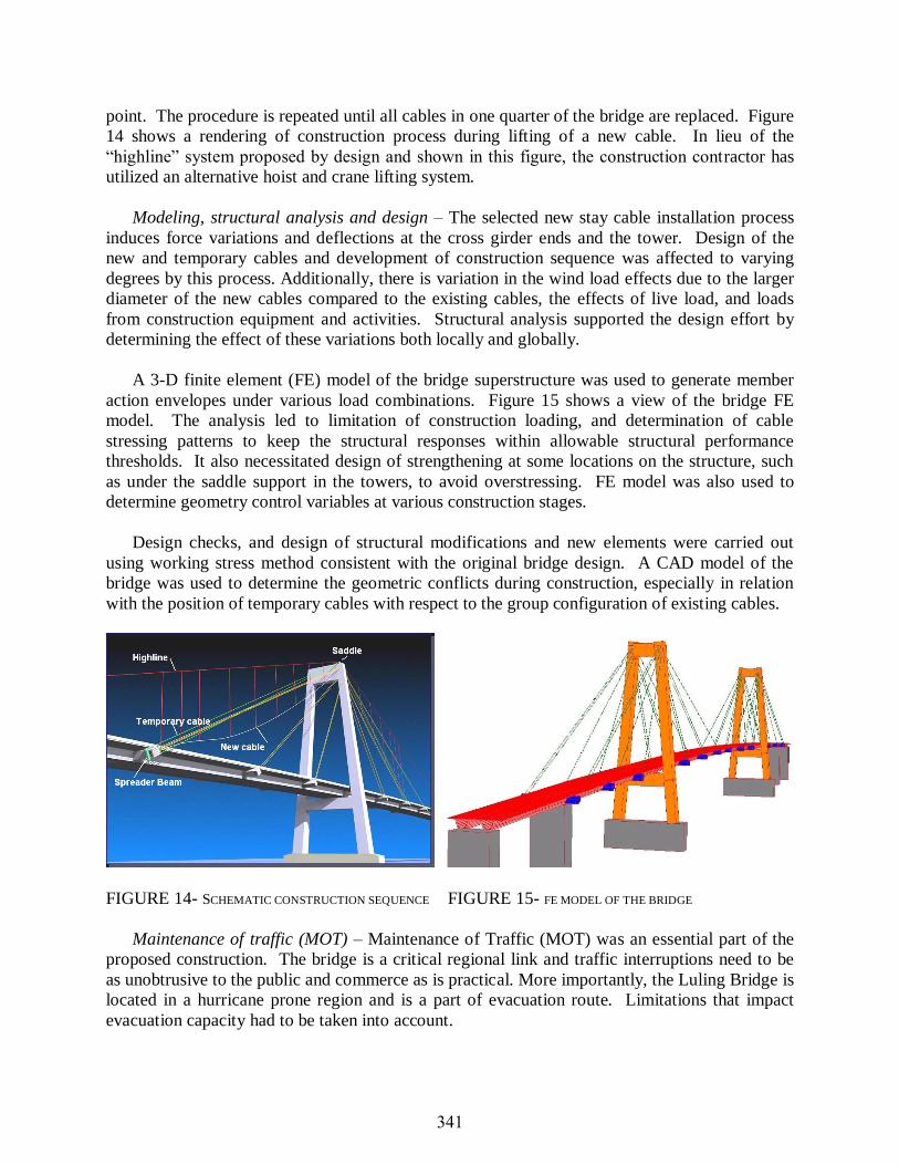
point. The procedure is repeated until all cables in one quarter of the bridge are replaced. Figure
14 shows a rendering of construction process during lifting of a new cable. In lieu of the
“highline” system proposed by design and shown in this figure, the construction contractor has
utilized an alternative hoist and crane lifting system.
Modeling, structural analysis and design – The selected new stay cable installation process
induces force variations and deflections at the cross girder ends and the tower. Design of the
new and temporary cables and development of construction sequence was affected to varying
degrees by this process. Additionally, there is variation in the wind load effects due to the larger
diameter of the new cables compared to the existing cables, the effects of live load, and loads
from construction equipment and activities. Structural analysis supported the design effort by
determining the effect of these variations both locally and globally.
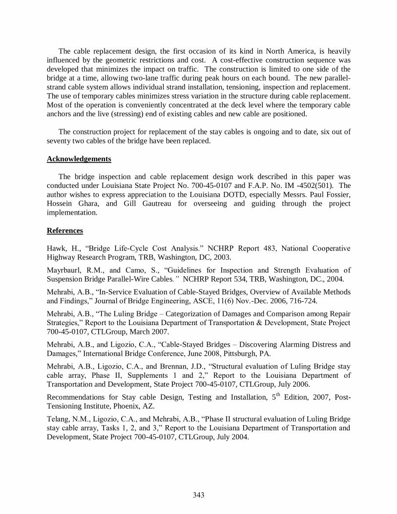
A 3-D finite element (FE) model of the bridge superstructure was used to generate member
action envelopes under various load combinations. Figure 15 shows a view of the bridge FE
model. The analysis led to limitation of construction loading, and determination of cable
stressing patterns to keep the structural responses within allowable structural performance
thresholds. It also necessitated design of strengthening at some locations on the structure, such
as under the saddle support in the towers, to avoid overstressing. FE model was also used to
determine geometry control variables at various construction stages.
Design checks, and design of structural modifications and new elements were carried out
using working stress method consistent with the original bridge design. A CAD model of the
bridge was used to determine the geometric conflicts during construction, especially in relation
with the position of temporary cables with respect to the group configuration of existing cables.
FIGURE 14- SCHEMATIC CONSTRUCTION SEQUENCE FIGURE 15- FE MODEL OF THE BRIDGE
Maintenance of traffic (MOT) – Maintenance of Traffic (MOT) was an essential part of the
proposed construction. The bridge is a critical regional link and traffic interruptions need to be
as unobtrusive to the public and commerce as is practical. More importantly, the Luling Bridge is
located in a hurricane prone region and is a part of evacuation route. Limitations that impact
evacuation capacity had to be taken into account.
341

Practical traffic control sequences were identified and their impact on traffic was determined
and communicated with LADOTD. These sequences had to also accommodate for the
construction activities. Among those considered, two sequences; for Peak and Off-Peak Traffic
Operations, were identified that would serve both purposes; minimizing impact on traffic and
allowing cost-effective construction operation.
The Luling Bridge carries two lanes of traffic on each bound with a 10-ft right shoulder and
4.25-ft left shoulder on each bound. It was determined that most of the cable replacement
operation can be carried out within a 12.25-ft space separated on the right side of the deck by
concrete barriers (2 ft wider than the existing shoulder). During Peak Traffic, this pattern allows
two lanes of traffic, 11-ft each, on the construction side of the bridge without shoulders, and
normal traffic pattern on the other side. Figure 16 shows Peak Traffic Operation sequence for
the construction side of the bridge. When necessary, during Off-Peak Traffic in the evenings or
weekends, the construction space is widened from 12.25 to 23.25 ft using plastic cones allowing
operation of heavier and wider equipment and other activities. This pattern allows one 11-ft lane
of traffic lane without shoulder on the construction side while traffic on the other side of the
bridge flows normally. These patterns have been working smoothly without significant
interruptions to traffic since the start of the construction activities on the bridge.
Few instances of short-term bridge closures were anticipated in design. The contractor has
used these occasions for lifting heavy and large equipment and framework to the top of the
tower. With the construction sequence and MOT design developed for this project, there has
been no restriction to the river main navigation channel.
FIGURE 16- MAINTENANCE OF TRAFFIC FOR CONSTRUCTION SIDE FOR PEAK TRAFFIC OPERATION SEQUENCE
Summary
Inspections of Luling Bridge found a variety of critical damages to the protective sheathing
and exposure of the main tension elements of the stay cables, with an increasing rate of
degradation. Prior to attempting repairs, a life-cycle-cost analysis (LCCA) was performed to
assist the decision making for maintenance. Considering the LCCA results along with
uncertainties in the level of potential damages, the effect of costs not included in the analysis,
and more importantly, concerns related to highway network system and public safety, LADOTD
decided to replace all cables.
342
The cable replacement design, the first occasion of its kind in North America, is heavily
influenced by the geometric restrictions and cost. A cost-effective construction sequence was
developed that minimizes the impact on traffic. The construction is limited to one side of the
bridge at a time, allowing two-lane traffic during peak hours on each bound. The new parallel-
strand cable system allows individual strand installation, tensioning, inspection and replacement.
The use of temporary cables minimizes stress variation in the structure during cable replacement.
Most of the operation is conveniently concentrated at the deck level where the temporary cable
anchors and the live (stressing) end of existing cables and new cable are positioned.
The construction project for replacement of the stay cables is ongoing and to date, six out of
seventy two cables of the bridge have been replaced.
Acknowledgements
The bridge inspection and cable replacement design work described in this paper was
conducted under Louisiana State Project No. 700-45-0107 and F.A.P. No. IM -4502(501). The
author wishes to express appreciation to the Louisiana DOTD, especially Messrs. Paul Fossier,
Hossein Ghara, and Gill Gautreau for overseeing and guiding through the project
implementation.
References
Hawk, H., “Bridge Life-Cycle Cost Analysis.” NCHRP Report 483, National Cooperative
Highway Research Program, TRB, Washington, DC, 2003.
Mayrbaurl, R.M., and Camo, S., “Guidelines for Inspection and Strength Evaluation of
Suspension Bridge Parallel-Wire Cables.” NCHRP Report 534, TRB, Washington, DC., 2004.
Mehrabi, A.B., “In-Service Evaluation of Cable-Stayed Bridges, Overview of Available Methods
and Findings,” Journal of Bridge Engineering, ASCE, 11(6) Nov.-Dec. 2006, 716-724.
Mehrabi, A.B., “The Luling Bridge – Categorization of Damages and Comparison among Repair
Strategies,” Report to the Louisiana Department of Transportation & Development, State Project
700-45-0107, CTLGroup, March 2007.
Mehrabi, A.B., and Ligozio, C.A., “Cable-Stayed Bridges – Discovering Alarming Distress and
Damages,” International Bridge Conference, June 2008, Pittsburgh, PA.
Mehrabi, A.B., Ligozio, C.A., and Brennan, J.D., “Structural evaluation of Luling Bridge stay
cable array, Phase II, Supplements 1 and 2,” Report to the Louisiana Department of
Transportation and Development, State Project 700-45-0107, CTLGroup, July 2006.
Recommendations for Stay cable Design, Testing and Installation, 5th Edition, 2007, Post-
Tensioning Institute, Phoenix, AZ.
Telang, N.M., Ligozio, C.A., and Mehrabi, A.B., “Phase II structural evaluation of Luling Bridge
stay cable array, Tasks 1, 2, and 3,” Report to the Louisiana Department of Transportation and
Development, State Project 700-45-0107, CTLGroup, July 2004.
343