Embed Size (px)
Citation preview

STATUS OF THE SEISM EXPERIMENT*
M. Marie-Jeanne, J. Angot, P. Balint, C. Fourel, G. Freche, J. Giraud, J. Jacob, T. Lamy, L. Latrasse, P. Sole, P. Sortais, and T. Thuillier, LPSC UJF CNRS/IN2P3 INPG, Grenoble, France
F. Debray, C. Trophime, S. Veys, and C. Daversin, LNCMI CNRS UJF, Grenoble, France V. Zorin, I. Izotov, and V. Skalyga, IAP, Nizhny Novgorod, Russia
Abstract LPSC Grenoble has developed the first and unique
confinement structure in the world that allows a closed 60 GHz ECR zone, using advanced magnet technology from Grenoble High Magnetic Field Laboratory (LNCMI). The magnetic structure was validated for 28 GHz resonance and a closed 1 T iso-B surface was measured. Discrepancies between calculated and measured field maps were extensively studied in order to determine a working range for 28 GHz plasma tests. A whole test bench, including high pressure water for helix cooling, intense currents (up to 15 kA) for helix powering and a beamline with mass separation is under construction at LNCMI. This contribution presents the status of the experiment.
SEISM MAGNETIC STRUCTURE Initial Design
The SEISM prototype is based on a magnetic cusp, designed to reach 7 T at the injection, 3.5 T at the extraction and 4.5 T on the radial mirror [1]. A short axial mirror length (100 mm) is possible thanks to the use of polyhelix resistive coils developed by LNCMI Grenoble. Magnetic field measurements [2] confirmed that this configuration could produce a closed 1 T iso-B surface (see Fig.1), thus allowing the resonance at 28 GHz.
Figure 1: Iso-B map in the prototype at 15000 A.
However, one observed that the resonance zone had a
9 mm shift towards the extraction that remains unexplained. This shift was carefully investigated, as well as the consequences for the source design and operation.
Investigation of the Magnetic Shift First, an independent measurement based on the
magnetic field flux variation was performed with a 0.1 mm step along the central axis at low current (146 A). A 6 mm shift was found.
Then, both injection and extraction water tanks containing the helices were taken apart and their dimensions were checked with CAO drawings. No assembly error was found.
Finally, a new measurement was performed at low current (50 A and 100 A) after assembling the source parts between the tanks, and a 5 mm shift was found. This 5 mm shift is consistent with 2D simulations performed with FEMM software.
Consequences for the Source Design Magnetic field configuration provides crucial
information for the design of the plasma chamber and of the microwave injection.
Concerning the plasma chamber, such displacement of the magnetic field centre may cause energetic electrons crossing the resonance zone to hit and damage the plasma chamber walls. In the present case, plasma chamber dimensions are already constrained by the magnetic structure assembly. A solution was investigated to adjust the current ratio between injection and extraction coils in order to centre the resonance zone. For Iinj/Iext=0.8, the cusp point is centred (see Fig. 2), which corresponds to 15 kA maximal intensity delivered by LNCMI power supplies on extraction coils and 12 kA on injection coils for 28 GHz resonance. In order to allow more flexibility on the coils current for the first beam tests, one decides to start with a 18 GHz plasma, which we expect to confine more.
___________________________________________
*Work supported by EuroMagNET II under the EU contract number 228043.
Proceedings of ECRIS2012, Sydney, Australia WEZO01
Next Generation ECRIS
ISBN 978-3-95450-123-6
111 Cop
yrig
htc ○
2012
CC
-BY-
3.0
and
byth
ere
spec
tive
auth
ors

Figure 2: Magnetic field lines for a centred cusp in the prototype.
As for the microwave injection, one needs to avoid
plasma flow into the waveguide, thus inducing undesirable discharge outside the trap. For first tests at 18 GHz and 28 GHz, microwave is injected off the source central axis, and the transmission window is protected by a turn of the injection waveguide. However, plasma chamber will be modified in order to connect the 60 GHz microwave launch.
SEISM BEAM TEST BENCH Source Assembly
The plasma chamber was built according to initial design, with a 60 mm diameter and a 80 mm length. The 20 mm-wide shoulder at the centre allows magnetic field lines to pass from axial to radial mirrors through the resonance zone without touching the chamber walls. A polarized ring was added to prevent radial particle leaks. The plasma chamber is insulated by 2 mm thick PEEK parts. High-voltage (HV) is fed through the radiofrequency (RF) tube. As a first approach, conventional single-gap plasma and puller electrodes were designed, with respective extraction hole diameters of 8 mm and 13 mm. The gap can be varied between 17 and 54 mm.
Figure 3 shows the assembly of the source. Vacuum tests were performed on the source elements prior to assembly. The plasma chamber could be inserted without opening the helices cooling tanks.
Figure 3: Steps for assembling the source, with (A) vacuum tests of the source parts, (B) taking apart injection and extraction tanks, (C) inserting the plasma chamber and (D) assembling both tanks. Puller electrode is inserted from the extraction flange side.
Beamline A simple beamline was installed: the source is
connected to a 102° magnetic dipole for mass selection and then to a water-cooled Faraday cup. Pumping is achieved by two 240 l/s turbopumps placed before and after the dipole. A 20 kV voltage is applied on the plasma chamber.
Argon gas is injected through a manually controlled grounded valve. Ion current is measured via a Keithley picoammeter.
Magnet Infrastructure SEISM beam test bench was installed in a dedicated
room at LNCMI, with direct hydraulic and electrical connections to the facility. A high de-ionized water flow (20 l/s) was delivered by the facility in order to cool the helices. Injection and extraction coils resistance were monitored to prevent any cooling problem. Injection and extraction coils were respectively connected to independent power supplies delivering up to 15 kA currents each. A scheme of the installation is shown in Fig. 4.
WEZO01 Proceedings of ECRIS2012, Sydney, Australia
ISBN 978-3-95450-123-6
112Cop
yrig
htc ○
2012
CC
-BY-
3.0
and
byth
ere
spec
tive
auth
ors
Next Generation ECRIS
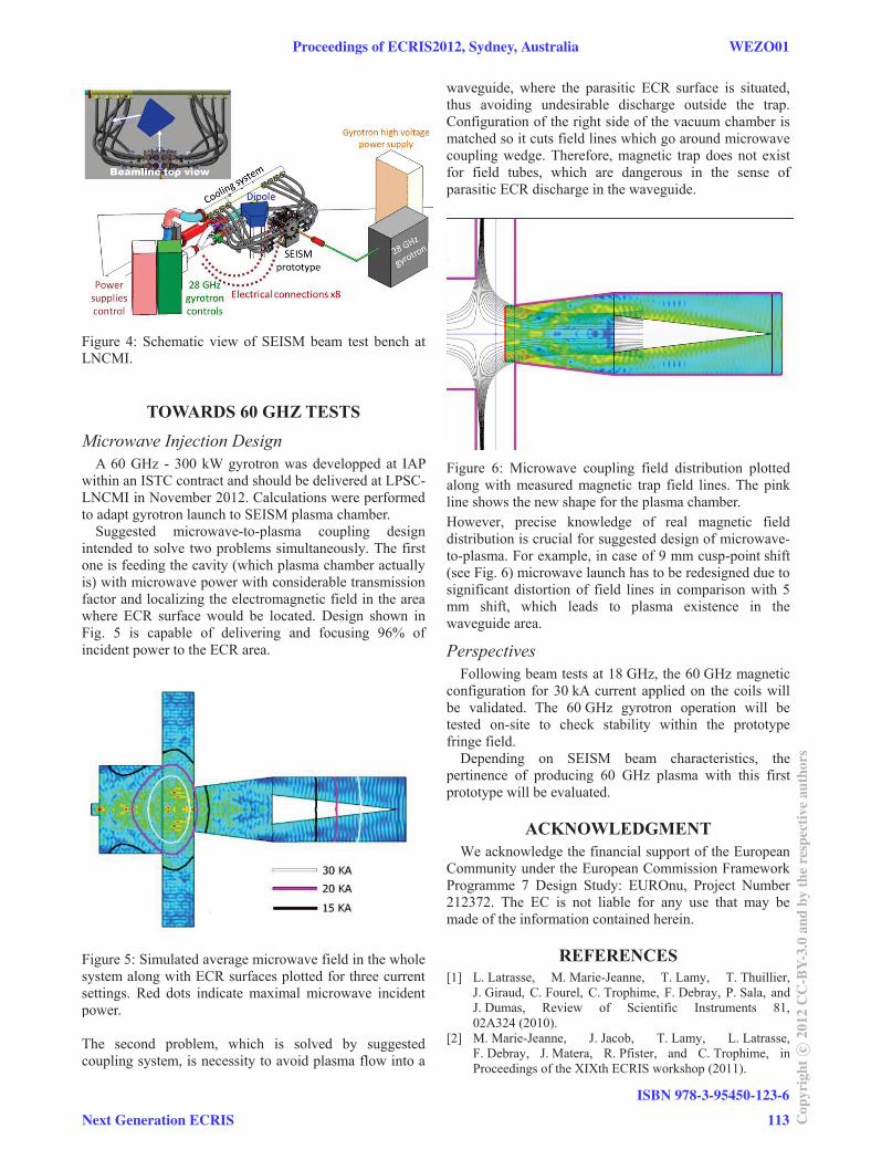
Figure 4: Schematic view of SEISM beam test bench at LNCMI.
TOWARDS 60 GHZ TESTS Microwave Injection Design
A 60 GHz - 300 kW gyrotron was developped at IAP within an ISTC contract and should be delivered at LPSC-LNCMI in November 2012. Calculations were performed to adapt gyrotron launch to SEISM plasma chamber.
Suggested microwave-to-plasma coupling design intended to solve two problems simultaneously. The first one is feeding the cavity (which plasma chamber actually is) with microwave power with considerable transmission factor and localizing the electromagnetic field in the area where ECR surface would be located. Design shown in Fig. 5 is capable of delivering and focusing 96% of incident power to the ECR area.
Figure 5: Simulated average microwave field in the whole system along with ECR surfaces plotted for three current settings. Red dots indicate maximal microwave incident power. The second problem, which is solved by suggested coupling system, is necessity to avoid plasma flow into a
waveguide, where the parasitic ECR surface is situated, thus avoiding undesirable discharge outside the trap. Configuration of the right side of the vacuum chamber is matched so it cuts field lines which go around microwave coupling wedge. Therefore, magnetic trap does not exist for field tubes, which are dangerous in the sense of parasitic ECR discharge in the waveguide.
Figure 6: Microwave coupling field distribution plotted along with measured magnetic trap field lines. The pink line shows the new shape for the plasma chamber. However, precise knowledge of real magnetic field distribution is crucial for suggested design of microwave-to-plasma. For example, in case of 9 mm cusp-point shift (see Fig. 6) microwave launch has to be redesigned due to significant distortion of field lines in comparison with 5 mm shift, which leads to plasma existence in the waveguide area.
Perspectives Following beam tests at 18 GHz, the 60 GHz magnetic
configuration for 30 kA current applied on the coils will be validated. The 60 GHz gyrotron operation will be tested on-site to check stability within the prototype fringe field.
Depending on SEISM beam characteristics, the pertinence of producing 60 GHz plasma with this first prototype will be evaluated.
ACKNOWLEDGMENT We acknowledge the financial support of the European
Community under the European Commission Framework Programme 7 Design Study: EUROnu, Project Number 212372. The EC is not liable for any use that may be made of the information contained herein.
REFERENCES [1] L. Latrasse, M. Marie-Jeanne, T. Lamy, T. Thuillier,
J. Giraud, C. Fourel, C. Trophime, F. Debray, P. Sala, and J. Dumas, Review of Scientific Instruments 81, 02A324 (2010).
[2] M. Marie-Jeanne, J. Jacob, T. Lamy, L. Latrasse, F. Debray, J. Matera, R. Pfister, and C. Trophime, in Proceedings of the XIXth ECRIS workshop (2011).
Proceedings of ECRIS2012, Sydney, Australia WEZO01
Next Generation ECRIS
ISBN 978-3-95450-123-6
113 Cop
yrig
htc ○
2012
CC
-BY-
3.0
and
byth
ere
spec
tive
auth
ors