Embed Size (px)
Citation preview

http://cer.sagepub.com/Concurrent Engineering
http://cer.sagepub.com/content/6/4/345The online version of this article can be found at:
DOI: 10.1177/1063293X9800600407
1998 6: 345Concurrent EngineeringB. O'Shea, S.S. Grewal and H. Kaebernick
State of the Art Literature Survey on Disassembly Planning
Published by:
http://www.sagepublications.com
can be found at:Concurrent EngineeringAdditional services and information for
http://cer.sagepub.com/cgi/alertsEmail Alerts:
http://cer.sagepub.com/subscriptionsSubscriptions:
http://www.sagepub.com/journalsReprints.navReprints:
http://www.sagepub.com/journalsPermissions.navPermissions:
http://cer.sagepub.com/content/6/4/345.refs.htmlCitations:
What is This?
- Dec 1, 1998Version of Record >>
at UNIV CALIFORNIA SAN DIEGO on October 8, 2014cer.sagepub.comDownloaded from at UNIV CALIFORNIA SAN DIEGO on October 8, 2014cer.sagepub.comDownloaded from

345
State of the Art Literature Survey on Disassembly Planning
B. O’Shea
School of Mechanical and Manufacturing Engineering, University of New South Wales
S. S. Grewal*
CSIRO Manufacturing Science and Technology, P.O. Box 218, Lindfield, Sydney, Australia, 2070
H. Kaebernick
School of Mechanical and Manufacturing Engineering, University of New South Wales
Received August 10, 1998; accepted in revised form September 20, 1998
Abstract: In this paper, the state of the art of disassembly planning is detailed to the best of the authors knowledge. Covered are issuesthat have particular relevance to disassembly planning, from product representation, to task analysis, task representation, sequencing, clus-tering, life cycle engineering issues, and cost estimation. Materials data requirement issues and some practical applications in disassemblyplants are discussed In conclusion, this paper details future research with the aim of developing a robust and effective disassembly plan-ning methodology This will be based upon task actuation and the minimisation of components requiring assessment by the plan.
Key Words: disassembly planning, sequence generation, clustering, life cycle engineering
1. Introduction
In this paper the state of the art of disassembly planning isdetailed to the best of the authors’ knowledge. The objectiveis to develop a robust disassembly planning methodologyand a windows-based software tool for its implementationand use in industry. Very little research has concentratedupon disassembly planning as a whole, but rather, has fo-cused on some smaller section within the field. The authorsof this paper have broken disassembly planning into a
number of sub-units, to reflect the nature of the work of re-searchers to date. These sections are as follows: Product Rep-resentation, Task Representation, Clustering and Sequenc-ing, Life Cycle Engineering, Cost Estimation and Analysis,and finally an overview of the directions that future researchby the authors will follow. These classifications were aidedby studies completed by ElMaraghy et al. [44], whose paperlooks at the future path of CAPP and Pankam [24], VanBrussel [45] and Gupta [32] in their work relating to assem-bly and disassembly planning.Pankam [24] carries out a survey of the current state of the
art in the field of the disassembly of products for reuse andrecycling. He discusses (1) the hierarchy of disassembly andthe end use options that are associated with it, (2) the major
*Author to whom correspondence should be addressed
courses that current research into disassembly theory is
taking, (3) the effect of disassembly on product design, (4)process and system design in a disassembly plant, (5) the pri-mary disassembly techniques put forward by prominentauthors in the field, such as Sanderson and Bourjault, and fi-nally (6) disassembly cost, with a primary focus on the appli-cation of activity-based costing to disassembly planning.
Gupta [32] and McLean provide a recent review of thestate of the art of research in the disassembly of products,looking at recent works in the areas of ( 1) product design forease of disassembly, (2) disassembly process planning, (3)design and implementation of disassembly systems and (4)operations planning issues in the disassembly planning envi-ronment.
Van Brussel [45] provides a review of the state of the artresearch in assembly planning systems. Van Brussel sug-gests that creative tasks in assembly systems have tended tobe left to the human expert, while the repetitive tasks havebeen automated. He suggests that the next generation of plan-ning tools will handle a larger portion of the creative taskscurrently undertaken by the human expert.
2. Product Representation
Products that possess a net positive recovery value will re-quire disassembly planning at or before they reach the end of
Volume 6 Number 4 December 1998
1063-293X/98/04 0345-13 $10 00/0© 1999 Technomic Pubhshing Co , Inc
at UNIV CALIFORNIA SAN DIEGO on October 8, 2014cer.sagepub.comDownloaded from
346
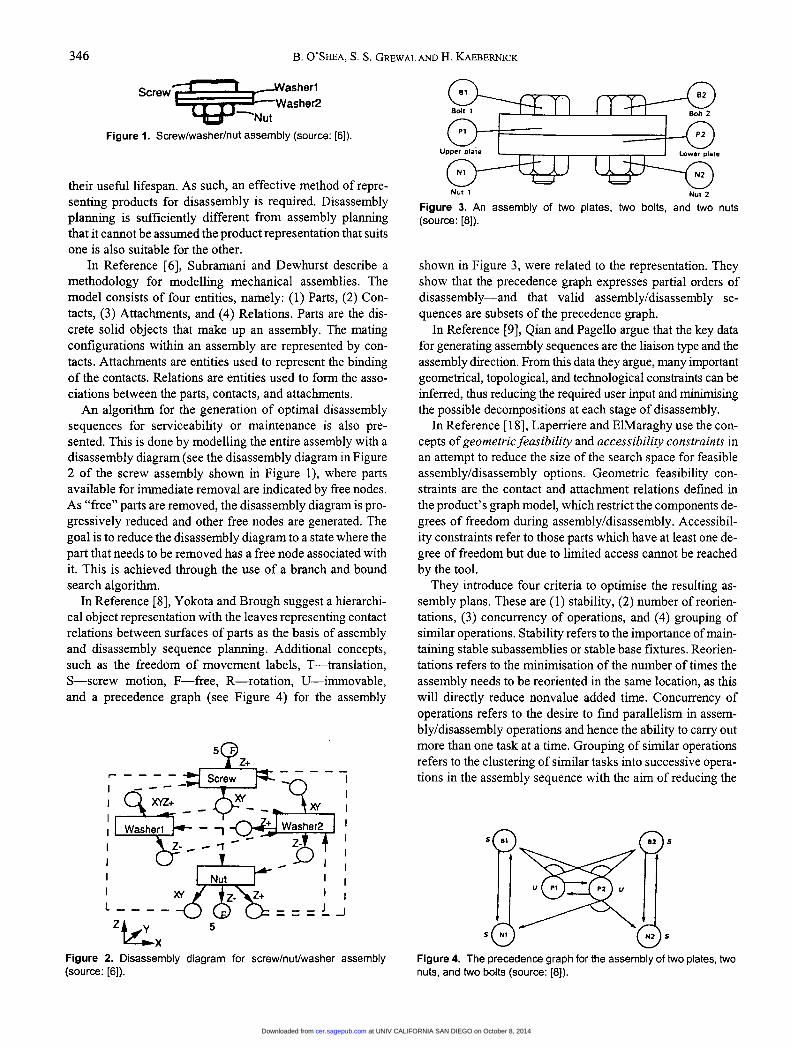
Figure 1. Screw/washer/nut assembly (source: [6]).
their useful lifespan. As such, an effective method of repre-senting products for disassembly is required. Disassemblyplanning is sufficiently different from assembly planningthat it cannot be assumed the product representation that suitsone is also suitable for the other.
In Reference [6], Subramani and Dewhurst describe amethodology for modelling mechanical assemblies. Themodel consists of four entities, namely: (1) Parts, (2) Con-tacts, (3) Attachments, and (4) Relations. Parts are the dis-crete solid objects that make up an assembly. The matingconfigurations within an assembly are represented by con-tacts. Attachments are entities used to represent the bindingof the contacts. Relations are entities used to form the asso-ciations between the parts, contacts, and attachments.An algorithm for the generation of optimal disassembly
sequences for serviceability or maintenance is also pre-sented. This is done by modelling the entire assembly with adisassembly diagram (see the disassembly diagram m Figure2 of the screw assembly shown in Figure 1), where partsavailable for immediate removal are indicated by free nodes.As &dquo;free&dquo; parts are removed, the disassembly diagram is pro-gressively reduced and other free nodes are generated. Thegoal is to reduce the disassembly diagram to a state where thepart that needs to be removed has a free node associated withit. This is achieved through the use of a branch and boundsearch algorithm.
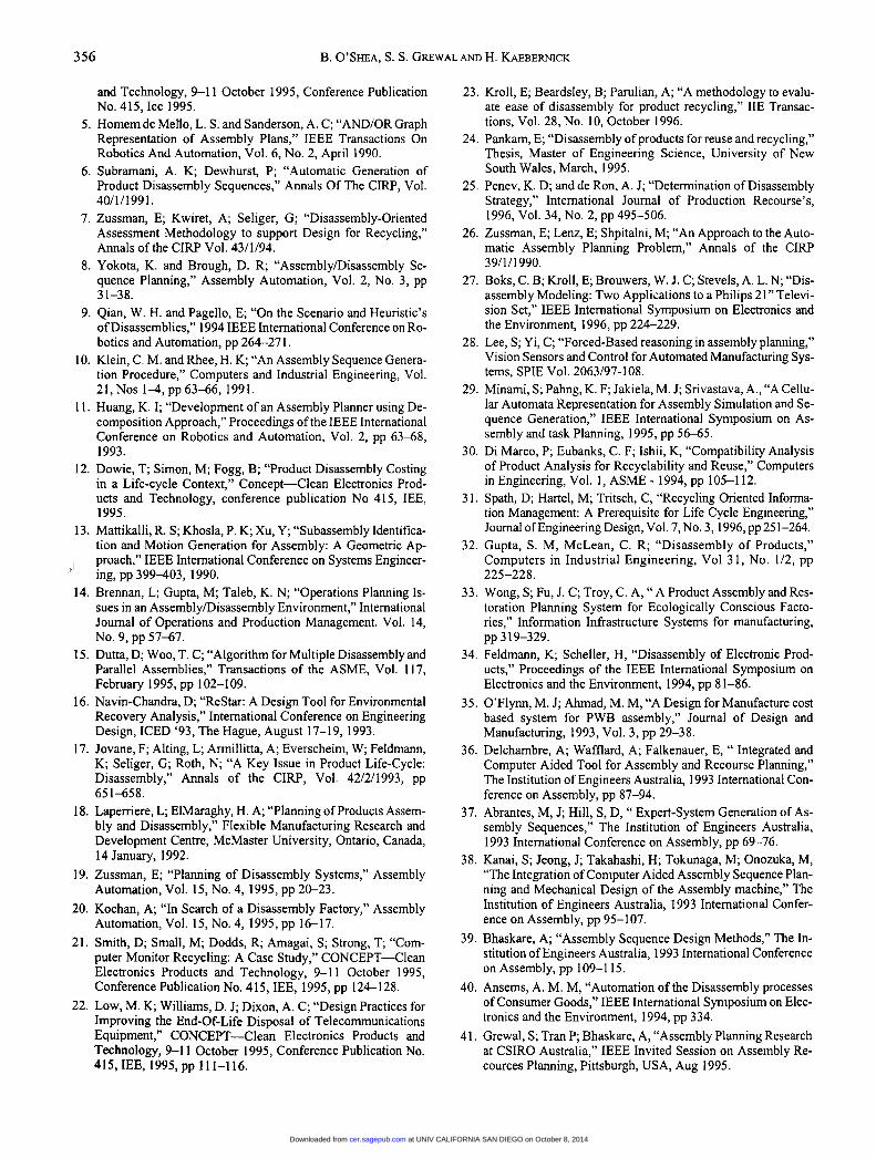
In Reference [8], Yokota and Brough suggest a hierarchi-cal object representation with the leaves representing contactrelations between surfaces of parts as the basis of assemblyand disassembly sequence planning. Additional concepts,such as the freedom of movement labels, T-translation,S-screw motion, F-free, R-rotation, U-immovable,and a precedence graph (see Figure 4) for the assembly
Figure 2. Disassembly diagram for screw/nut/washer assembly(source: [6]).
Figure 3. An assembly of two plates, two bolts, and two nuts(source: [8]).
shown in Figure 3, were related to the representation. Theyshow that the precedence graph expresses partial orders ofdisassembly-and that valid assembly/disassembly se-
quences are subsets of the precedence graph.In Reference [9], Qian and Pagello argue that the key data
for generating assembly sequences are the liaison type and theassembly direction. From this data they argue, many importantgeometrical, topological, and technological constraints can beinferred, thus reducing the required user input and minimisingthe possible decompositions at each stage of disassembly.
In Reference [18), Laperriere and ElMaraghy use the con-cepts of geometric feasibility and accessibility constraints inan attempt to reduce the size of the search space for feasible
assembly/disassembly options. Geometric feasibility con-straints are the contact and attachment relations defined inthe product’s graph model, which restrict the components de-grees of freedom during assembly/disassembly. Accessibil-ity constraints refer to those parts which have at least one de-gree of freedom but due to limited access cannot be reached
by the tool.They introduce four criteria to optimise the resulting as-
sembly plans. These are (1) stability, (2) number of reorien-tations, (3) concurrency of operations, and (4) grouping ofsimilar operations. Stability refers to the importance of main-taining stable subassemblies or stable base fixtures. Reorien-tations refers to the minimisation of the number of times the
assembly needs to be reoriented in the same location, as thiswill directly reduce nonvalue added time. Concurrency ofoperations refers to the desire to find parallelism in assem-bly/disassembly operations and hence the ability to carry outmore than one task at a time. Grouping of similar operationsrefers to the clustering of similar tasks into successive opera-tions in the assembly sequence with the aim of reducmg the
Figure 4. The precedence graph for the assembly of two plates, twonuts, and two bolts (source: [8]).
at UNIV CALIFORNIA SAN DIEGO on October 8, 2014cer.sagepub.comDownloaded from

347
number of setups and tool changes in the assembly/disassem-bly plan.
In Reference [26], Zussman et al., use an approach to theautomatic assembly planning problem which is based uponconstructing and analysing a relational graph which links as-sembly features. This relational graph (see Figure 6) basedupon the assembly in Figure 5, consists of a combination ofgeometric, topologic, and functional data. At the stage ofanalysing a product for assembly, the topological structure ofthe product is obtained and represented with the aid of a rela-tional graph between the assembly features of the objects.This graph is then simplified by combining the topologicalreferences of the product with the physical objects being con-sidered for assembly to create an Object graph (see Figure 7).This method of product representation is intended to form aneat fit with object oriented techniques for any future
computer-based system.In Reference [28], Lee and Yi, present an assembly plan-
ning system COPLANNER for integration of work such asCAD, geometric modelling, geometric and physical reason-ing, and assembly process scheduling. The authors representthe product, in this case a flashlight assembly (see Figure 8),through the use of an Attributed Liaison Graph (see Figure 9),
Figure 5. (a) Assembled product; (b) assembly features of the objec-tives (source: [26]).
Figure 6. The relational graph (source: [26]).
Figure 7. (a) Relational graph on object level; (b) object graph(source: [26]).
Figure 8. An assembly of a flashlight (source: [68]).
Figure 9. The attributed liaison graph for the flashlight assembly(source: [68]).
at UNIV CALIFORNIA SAN DIEGO on October 8, 2014cer.sagepub.comDownloaded from

348
which highlights the parts and their geometric and physicalrelations and is similar to the Object graph later used byZussman et al. The disassembly plan is represented throughthe use of a Hierarchical Partial-Order Graph (derived fromHomem de Mello’s AND/OR graph). This provides informa-tion pertaining to both the precedence relations among as-sembly operations and the temporal and spatial parallelismfor implementing distributed and cooperative assembly.The authors provide a definition for an Assembly opera-
tion as being &dquo;a process of joining two or more discrete partsto form a new one,&dquo; and define the assembly plan as being&dquo;the generated sequence of assembly operations.&dquo; The
authors also use the concept of &dquo;Surface Normal Vectors&dquo; asa means of showing the rectilinear degrees of freedom of anypart in the product. A surface normal vector (SNV) is a vec-tor of which origination is perpendicular to each contactplane of a part and pointing toward another part. If the SNVpoints to no other part, this represents a degree of freedom.
With the use of cellular automata, part motion for assem-
bly/disassembly is achieved by shifting the material of partsinto neighbouring cells. The cell movement rules shift cellsalong the direction of their possible motion by one cell unit.There are three sets of possible motion propagation rules,these are propagation within a component, blocking motion,and propagation beyond part boundary.
In Reference [29], Minami et al. construct a cellular auto-mata representation for assembly simulation and sequencegeneration. The authors seek a representation of the productthat allows rapid geometric reasoning and facilitates iterativemodification of part geometry, while still representing thepart geometry adequately. Cellular automata are used to rep-resent physical objects and their interactions for the purposeof planning the assembly process of many parts. Cells of thesame part are given the same part label number. They assumea vector value made up of a material/void indicator, a set ofcell boundary edge states, and an indicator of the allowablemotion of direction of the cell.
In Reference [34], Feldmann and Scheller discuss the dis-assembly of electronic products, primarily printed circuitboards (PCBs). In their paper they make the distinction be-tween two types of parts: (1) elements of connection and (2)elements of function. Hence, the authors recognise that dif-ferent components have different roles in the product andshould therefore be treated differently. The authors then goon to suggest the use of two broad principles in disassemblyplanning, those of &dquo;Look and Pick&dquo; and &dquo;Evacuate and Sort.&dquo;Where &dquo;Look and Pick,&dquo; refers to the disassembly of specificcomponents from the remaining assembly and &dquo;Evacuate andSort&dquo; refers to the immediate breakdown of the whole prod-uct and a subsequent sorting process to remove valuablecomponents.
In Reference [37], Abrantes generates assembly se-
quences using an expert system. Using the basic format laidout by Sanderson and Homem de Mello for assembly repre-sentation using the AND/OR graph (see Figure 10). Abrantesapplies a rule-based system for the purpose of interrogating
Figure 10. The AND/OR graph for a four component product(source: [5]).
generated assembly sequences to test for feasibility. The se-quence that is generated corresponds to the order in whichparts are to be added to the assembly. It does not consider thetasks or activities that generate cost in the assembly system.
2.1 Future Research
To develop an effective disassembly planning methodol-ogy, it is necessary to understand the disassembly process. Itis clear that one of the fundamental differences between as-
sembly and disassembly is the way in which subassembliesare created. In assembly, subassemblies are built aroundfunction, for example, an automotive radiator or starter mo-tor. In disassembly, subassemblies must necessarily be builtaround end-use. For example, parts with a common end-usewill be removed to a common end point in the disassemblyprocess.
The authors intend to use an object-based model
[6,8,26,28,34] for product representation. This model will bedesigned specifically for disassembly planning. It is envis-aged that the model will represent the product as some com-bination of three separate basic component types: the func-tional part, the fastener part, and the intangible fastener part.The model will also use two forms of link, those of fasteninglink and constraint link, to distinguish between componentinteraction options in the product.
3. Task Analysis and Representation
In Reference [13], Mattikalli et al. propose to make assem-bly evaluations based on knowledge about the details of the as-sembly process. Using a geometric model of a mechanical as-
at UNIV CALIFORNIA SAN DIEGO on October 8, 2014cer.sagepub.comDownloaded from

349
sembly, they systematically determine the tasks that build themechanical assembly. They argue that there are two principalsteps involved in achieving this: (1) subassemblies must beidentified and (2) detailed assembly motions of each subassem-bly must be found. At this point, the authors argue &dquo;everymotion of a subassembly can be mapped to an assembly task. Anassembly task represents a high level assembly process plan....&dquo;Effectively, the authors map the tasks required to develop anassembly or subassembly into the final product.
In Reference [23], Kroll et al. introduce quantitative meas-ures and a procedure for evaluating the ease of disassemblyof products when recycling them. They use a rating schemethat allows the designer to translate form properties of a de-sign into quantitative scores, providing a means of identify-ing weaknesses in the design and comparing alternatives.Difficulty ratings are provided in five subjective areas of thedesign: (1) Accessibility-this is a measure of the ease withwhich a part can be reached by the required tool, (2) Posi-tion-this is a measure of how precisely the tool needs to bepositioned and orientated to do the task, (3) Force-this is ameasure of the force required to do the task, (4) Additionaltime-this enables additional time penalties to be added, forexample, when nonstandard screw lengths are used, and (5)Special-this is a provision for special cases.
Data for a design is filled into a worksheet very similar tothat of the DFA worksheet. The authors draw from the
Boothroyd-Dewhurst method and apply it to disassembly.Each part is entered into the worksheet and the task requiredto remove it is entered beside it. More than one task can be
accommodated. The sequence of disassembly is decided
manually before the worksheet is used, just as is the case inDFA.
In order to complete the analysis, a design efficiency rat-ing for the disassemblability of the product is calculated. Atheoretical design efficiency is also calculated usingBoothroyd and Dewhurst’s three questions in DFA. The ex-isting design is then reviewed in an attempt to maximise im-provements. Kroll’s worksheet shows the application of taskgroups to parts. Further, the article highlights a number oftask types unique to disassembly, such as &dquo;pry_out,&dquo; &dquo;peel,&dquo;and &dquo;deform.&dquo;
In Reference [39], Bhaskare proposes an approach to as-sembly planning in which sequence planning is analysed as adynamic activity consisting of tasks performed on parts in aparticular order. He suggests a method based upon an inter-active technique of sequence generation, calling upon humanexperts and focusing upon task or activity sequencing in theassembly process, rather than part sequences. Bhaskare ar-gues that this is the correct approach since assembly cost isdirectly driven by the activities involved rather than the com-ponents in the assembly. In References [41,42,46], Grewal etal. further developed the concept that the actuation of tasks isthe primary driver of assembly planning. They then pursue inmore detail the issues involved in data design and interfacedesign in developing an integrated software package for as-sembly planning.
In Reference [40], Annsems argues that disassembly re-quires high flexibility and suggests that the disassembly fac-tory should be based upon the concept of parallel workingstations with different functions. He goes on to state that
these working cells should be arranged in side loops off amain conveyor line, such that different parking and workingstations can be defined.
In Reference [50], Kroll describes a method for evaluatingthe ease of disassembly of products with application as a de-sign tool for improving disassemblability. Kroll identifiesfour different sources of difficulty in performing dismantlingtasks. These are: (1) Accessibility-the ease with which apart can be reached by the hand or tool; (2) Positioning-themeasure of the degree of precision required to place to tool orhand; (3) Force-a measure of the effort required to do thetask, and (4) Base-Time-this is the time required to do thebasic movements without difficulty. In the method each ofthese sources of difficulty is rated on an integer scale be-tween 1 (easiest) and 10 (hardest).
The method applies the MOST [76] work measurementsystem to product disassembly to find the quickest and mostefficient method for performing a task under average condi-tions. This is designated as the standard task model. Thisstandard task model becomes an ideal from a design for dis-assembly viewpoint. To the standard task model, difficultyweightings are applied to reflect the actual situation in theproduct under consideration. Data for the entire product isbuilt and areas with potential for the greatest improvement indisassemblability can be identified.
In Reference [51] ] Sanderson et al. apply two algorithms tothe basic AND/OR graph model of disassembly sequences tolimit the search space and find feasible disassembly se-quences. The first is called the &dquo;Solve-Assembly&dquo; algorithmwhich takes as input a node corresponding to a subassembly,checks whether that node is terminal, and if not, spawns de-scendant tasks to be solved by an algorithm called &dquo;Solve-Task.&dquo; Solve-Task in turn, takes as input one task and handsall the nodes that result from that task back to Solve-
Assembly. Thus, infeasible sequences drop out of the systemas they are encountered. The tasks referred to are the variousforms of the disassembly task. They do not refer to any disas-sembly enabling tasks such as tool change, fixture change,etc.
In Reference [69] Kanai et al. evaluate the differencesamong feasible disassembly sequences. They have devel-oped a computer-aided Assembly Sequence Planning andEvaluatioN (ASPEN) system for this purpose. ASPEN auto-matically searches all geometrically feasible sequences bydecomposing solid models of the product. That is, the
authors use the decomposition approach to fmding feasibledisassembly sequences, by first fmding feasible disassemblysequences and then reversing them. The authors use prede-termined time standards, pointedly MTM and the DFA datasheets, for the purposes of assigning assembly times to thefeasible sequences. By this method, the optimum sequence isselected as the sequence requiring the least time to assemble.
at UNIV CALIFORNIA SAN DIEGO on October 8, 2014cer.sagepub.comDownloaded from

350
3.1 Future Research
Disassembly planning requires the manipulation and
analysis of information pertaining to the activities required todismantle a product. That is, although the physical compo-nents recovered from the product possess a particular value,the tasks required to disassemble components generate costs.It follows that the more efficient the disassembly plan, thelower will be the cost incurred in recovering value from theproduct.To achieve effective task representation in disassembly
planning, the authors agree with Grewal et al. [41,42,46] thatthe actuation of tasks is the primary driver of disassemblyplanning. The authors intend to develop a method throughwhich tasks are grouped around individual componentsand/or the remaining assembled product in order to effec-tively map cost to the disassembly plan.
4. Sequencing and Clustering
In Reference [1], Vujosevic et al. develop a procedure formodelling mechanical assemblies and all geometrically fea-sible disassembly sequences. This is achieved by focussingon a target part and assuming that &dquo;all other subassembliescan be removed in a single disassembly step.&dquo; According toVujosevic et al. &dquo;In order to generate all feasible disassemblysequences related to the target component, relationships be-tween components in corresponding mechanical assemblymust be defined. We use an approach that combines the fol-lowing two concepts:
~ Description of hierarchical (parent-child) relationships be-tween subassemblies and components in the mechanical
assembly.~ Qualitative description of relationships between subas-
semblies and between components within a subassembly.&dquo;
Further, they suggest that &dquo;Hierarchical relationships areneeded for the hierarchical composition of the overall disas-sembly sequence in terms of disassembly sequences that cor-respond to each level.&dquo; The assembly is modelled by qualita-tive labelling of relationships between components as
covers, is attached to, is connected to, is engaged with. Vujo-sevic et al. use manual clustering of component into subas-semblies before analysis begins.
Sanderson and Homem de Mello [5,66] present a compactrepresentation of all possible assembly plans of a product us-ing the concept of the AND/OR graph. They state &dquo;theAND/OR graph is equivalent to the state transition graph buthas fewer nodes and simplifies the search for feasible plans.&dquo;In the AND/OR graph the nodes represent the combinationsof disconnected parts and the connections highlight the pos-sible disassembly sequences. The sequence is then reversedto give the part order for assembly.
In Reference [10], Klein and Rhee develop an assemblysequence methodology that can be applied to series assem-
bly. They suggest that the assembly sequence should be gen-erated before the machine layout is fixed, thus overcomingany limitations associated with machinery, equipment, ortooling. All precedence problems and geometric constraintsof the product under consideration must be known by theuser.
Their methodology takes the following basic form: Dividethe product into subassemblies; draw a &dquo;component contact,task graph&dquo; (unfortunately, this graph is not given or referredto in the literature); measure the base operation time; list allof the needed combinations for the difficulty function; meas-ure the difficulty; and use dynamic programming to select asequence.
In Reference [ 11 ], Huang adopts a decomposition ap-proach to developing assembly sequence plans. He contendsthat a backward search will be more efficient than a forwardsearch for the assembly sequence planning problem, sincefewer possibilities are encompassed when starting from thefinal product and working back to its components. Thus, &dquo;theproblem of finding the way to assemble a given product canbe converted into an equivalent problem of finding out howthe same product can be disassembled.&dquo;The structure of Huang’s decomposition model can be
broken into four primary modules, these are (1) the feasibil-ity testing module, (2) the evaluation module, (3) the selec-tion module, and (4) the decomposition module. Feasibilitytesting checks whether a particular part can be removed inthe present assembly state. The evaluation module applies aset of subjective criteria to decide which of the feasible partsshould be removed next. The selection module weighs thevarious subjective criteria according to their relative impor-tance. Finally, the decomposition module generates the dis-assembly sequence for this stage of the assembly state.
In Reference [15], Dutta and Woo consider the geometricproblem of generating efficient sequences for disassemblingcomponents. They make the distinction between parallel andsequential assemblies by recognising the need to removewhole subassemblies from the product on occasions.They state the differences between assembly and disas-
sembly as follows, &dquo;In principle, every assembly is an in-stance of a jig-saw puzzle. Clearly, putting together the puz-zle is harder than breaking it up. For example, to disassembleit is necessary and sufficient to ’bring apart’ all pairs of mat-ing faces in the assembly. This is indirectly achieved bychecking for and removing the boundary components insome sequence. However, to assemble the components, it isnecessary to do the following: (1) recognise mating faces ofeach component, (2) recognise mating components for eachcomponent and (3) correctly orient each pair of componentsfor assembly.&dquo;
In Reference [31], Spath et al. present a computer aidedtool for product development with disassembly and recy-cling adequacy in mind. The authors then detail an approachfor achieving an optimised disassembly extent, but do not at-tempt to move forward from the suggested extent of disas-sembly to the creation of a disassembly plan.
at UNIV CALIFORNIA SAN DIEGO on October 8, 2014cer.sagepub.comDownloaded from

351
Delchambre et al., in Reference [36], break the planningprocess into two stages. The first of which is assembly plan-ning which covers the generation of precedence constraintsamongst components and the generation of the assembly se-quence. The second stage is defined by the authors as re-course planning and covers the quantity of stations along theassembly line, the operations performed at each station, andthe relative location of each station on the shop floor.The authors prune the search tree in assembly sequencing
by applying constraints to the search algorithm. The authorsalso suggest the use of part clustering for speeding the assem-bly sequencing process, this clustering process is simply theidentification of subassemblies in the product.
In Reference [38], Kanai et al. develop a computer aidedsystem for assembly sequence planning and the mechanicaldesign of the assembly machine. The assembly sequence fo-cuses on part order, the assembly structure model is repre-sented by showing the fastening relationships among parts,the contact relationships among parts and the relative stabil-ity of each part in the assembly.
In Reference [2], Johnson and Wang state that &dquo; in order toremain economically viable, it is important to remove highvalue items first and then remove items with diminishingvalue.&dquo; They introduce the concepts of the disposal clusterand the material cluster, which are used to describe thegrouping of components for common end-use in order tolimit the search space of the sequencing algorithm.
Johnson and Wang use a profit/loss margin (PLM) indexto ascertain the extent to which disassembly should be car-ried out. In this methodology an optimal disassembly se-quence is generated first, then they suggest that at PLMmaxthe optimum disassembly extent has been reached.
Laperriere and ElMaraghy [67] describe a Generative As-sembly Process Planner GAPP which is used to generate andevaluate assembly sequence alternatives. The authors firstdescribe an appropriate method for representing the productto aid assembly planning. This model defines components-a solid element added to the assembly during the assemblyprocess; contact-a relationship that occurs when two com-ponents are in constant physical contact, but the reorientationof one component with respect to the other allows the contact
Figure 11. Exploded diagram of air cylinder assembly (source: [67]).
Figure 12. Directed graph model of the air cylinder (source: [67]).
to be broken; attachment-a relationship between two com-ponents that are in constant physical contact in the productand that do not move relative to one another; and block-ing-a relationship where two components have no physicalcontact but that the motion of one component in a possibledisassembly direction will cause a collision between the twocomponents. By defining the product in this manner, theauthors are able to represent any product by the directedgraph model. An example of this directed graph model for anair cylinder assembly (Figure 11) is shown in Figure 12. Theauthors then investigate the cutsets of the graph model tobuild the assembly sequence. It is stated that &dquo;To each cutsetof the graph model there corresponds a disassembly opera-tion of the physical assembly which separates it into two sub-assemblies. New states are added to the directed graph repre-senting the subassemblies resulting from the disassemblyoperations. In turn, cutsets of the graph models of the addedstates are computed to give new states with smaller subas-semblies, and so on....&dquo; The concept of cutsets can be seenin Figure 13 of a hypothetical three subassembly product be-low. Figure 14 shows the corresponding directed graph of as-sembly states for this hypothetical product.The search space is pruned by adding constraints to the
system. These constraints include (1) geometric feasibilityconstraints, (2) accessibility constraints, (3) specification ofrestricted components, (4) avoidance of re-orientation of theproduct, (5) parallelism of the assembly sequence, (6) prod-uct stability during assembly, and (7) clustering of commonassembly tasks.
In Reference [68], Lee and Shin describe an assemblyplanning system based upon subassembly extraction that is
Figure 13. Formal approach to assembly sequence generationshowing the involvement of cutsets (source: [67]).
at UNIV CALIFORNIA SAN DIEGO on October 8, 2014cer.sagepub.comDownloaded from

352
Figure 14. Directed graph of assembly states for the hypotheticalproduct in Figure 13 (source: [67]).
designed for application in an environment of flexible manu-facturing which enables parallel assembly operations. Usingthe basic method described by Lee and Yi [28] in this paperrepresents a method for the automatic determination of as-
sembly sequences through the extraction of preferred subas-semblies. Subassemblies are selected by evaluating an initialestimate against a set of subassembly selection indices.
Bahtia et al. [70] use a connected graph derived from anexploded view of the product as a basis for robotic assemblysequencing. They then compare their approach to existing se-quencers like &dquo;AND/OR graph representation,&dquo; &dquo;directed
graph representation&dquo; and &dquo;precedence relationships repre-sentation.&dquo;
4.1 Future Research
The authors contend that the product should first be as-sessed for clustering possibilities before the products compo-nents are sequenced for disassembly. Clusters of componentscan be built when first, the components being clustered arefastened together, and second the components have a com-mon end-use. This will have the effect of minimising thenumber of components that need to be disassembled in the
product, thus reducing disassembly cost.The authors then intend to develop disassembly sequences
by focussing on the minimisation of nonvalue added tasks inthe disassembly plan as opposed to searching the AND/ORgraph or one of its derivatives [5,7,11,16,19,25].
5. Cost Estimation
In Reference [ 12], Dowie et al. argue, in their comparisonbetween DFD and DFA, that &dquo;design routes which depend onfuture re-sale values for components are high risk: experi-ence has shown that the prices for recyclate are unstable. Incontrast, disassembly time and cost predictions are more reli-able : they depend only on labour rates, which are relativelystable, and the degree of automation.&dquo; Hence, they argue thatthe correct strategy for design for disassembly is to minimisedisassembly cost rather than to maximise recyclable value.
In Reference [22], Low et al. state a number of case specificdesign rules for telephone manufacture to ease disassembly.Further to this, however, they comment on the practice ofleasing telephones adopted by many telecommunications
companies. &dquo;The traditional leasing of telephones and the re-turn of them in sufficiently large quantities has provided an in-frastructure that has been tolerably successful in providing amaterial recovery scheme.&dquo; This may provide a useful modelfor manufacturing companies in an era of recycling and reuse.
In Reference [25], Penev and de Ron outline a disassemblystrategy, the main aim of which is to determine the disassem-
bly level and the disassembly sequences which optimise costwhile meeting environmental obligations. The authors use amathematical cost model to trade off the possible disassem-bly &dquo;subprocesses&dquo; options for each component in the prod-uct. The subprocesses that they outline are Service, Disas-sembly, Dismantling, Recycling, and Disposal. Further, theauthors argue that each of these subprocesses represents adifferent disassembly level, which in turn, depends on anumber of economic considerations including the value
added to products and materials, the disassembly cost per op-eration, the revenues released per operation, and the penaltyif hazardous materials are not removed.
They apply this mathematical cost model to the AND/ORgraph concept developed by Sanderson and Homem deMello to generate all feasible disassembly sequences. Thecost model is used to determine the optimum sequence.
In Reference [27], Boks et al. describe two approaches todisassembly modelling, the first applies work-measurementanalysis to estimate disassembly times. The second approachuses actual dismantling processes to predict the disassemblytime of similar products. The authors state that time estimatesfor disassembly operations are critical to determining theease of disassembly of a product and its disassembly cost.They argue that time is the basic measure for the effective-ness of a disassembly model.
Through experimentation in the second approach, theauthors highlight four different sources of difficulty in per-forming dismantling tasks, these are accessibility-the ease bywhich a part can be reached; positioning-the degree of preci-sion required to locate the tool or hand; force-the effort re-quired to complete the task; and base time-the minimum timeto do the task given zero difficulty. Given the four sources ofdifficulty, the authors were then able to develop a subjectiverating for each task in the dismantling process. Hence, theyproduced an adjusted time for each dismantling task in the dis-assembly model and an overall disassembly time for the prod-uct under consideration. Only dismantling tasks are consideredin this approach; however, time estimates are adjusted to coverthe group of tasks associated with the dismantling task.
In Reference [35], O’Flynn and Ahmad describe a cost-based design for manufacture software system aimed specifi-cally at printed wire board (PWB) assembly and test. Theauthors carry out their cost analysis using a system of activity-based costing (ABC). The authors argue that ABC is the mosteffective accounting tool by which accurate information oncost can be generated in the manufacturing planning function.
In References [47] and [48] Compton details the basiccomponents of an Activity-Based Costing system (ABC).Amsler et al. [49], Combine ABC with Business Process
at UNIV CALIFORNIA SAN DIEGO on October 8, 2014cer.sagepub.comDownloaded from

353
Mapping in an attempt to improve product costing accuracy.Habil et al. [71 ] give an overview to the Life Cycle Costing(LCC) approach to product costing. In Reference [74] Em-blemsvaeg and Bras apply ABC in design for product retire-ment.
5.1 Future Research
In a similar fashion to Boks et al. [27], the authors intend touse work measurement analysis to calculate cost in the disas-sembly plan. As stated in the section Task Analysis and Rep-resentation, the authors intend to attach task groups to com-ponents in the product under assessment for disassembly.These task groups will then be used as anchors for cost as-
signment using work measurement analysis.
6. Life Cycle Engineering
In Reference [3], Chen et al. maintain that &dquo;Designingproducts for recyclability is driven by environmental andeconomic goals. It is important that we integrate both envi-ronmental and economic aspects of product design.&dquo; Further,they go on to propose a &dquo;cost and benefit analysis as an ap-proach that a decision maker can use to find the balance be-tween the amount of effort invested in the disassembly andrecycling of a product and the revenues that are realised.&dquo;
The authors develop a cost/benefit model looking primar-ily at the balance between the cost of recycling processes andthe benefits of material re-use. Further to this, they highlightthe importance of clustering components as a means of limit-ing the number and cost of disassembly operations.
In Reference [4], Boswell highlights four key areas of datafeedback from the recycling process (encompassing disas-sembly) to the design process, in an attempt to improve laterdesigns for disassemblability. The four areas of data collec-tion are &dquo;cost in the form of complexity and time, revenuesprovided in respect to the materials that can be liberated, en-vironmental impact in the form of residual material disposaland technical difficulty in the form of special tools, materialhandling, material identification....&dquo;
Boswell demonstrates his data collection framework
through the examination of a telephone switch recyclingproject. The project looks at finding an optimum extent ofdisassembly, at which point disassembly stops. He states,&dquo;This particular recycling project is selected because of theoverall economic return and the trade offs that are necessaryto generate the best economic return.&dquo; He goes on to statethat &dquo;Information is provided on materials that are liberatedduring the recycling process, costs incurred during the recy-cling process, environmental impact of waste materials, andcost trade-offs associated with further material liberalisa-
tion.&dquo;
In Reference [7], Zussman et al. introduce a quantitativeassessment tool that utilises statistical methods through theconcept of utility functions to predict the future cost of recov-ery at a product’s end-of-life (EOL). This information is then
used as a design tool in support of design for recycling. Twoaspects are critical for the assessment: first is the necessity tocombine multiple design objectives like cost minimisationand waste reduction. Second is the uncertainty regarding fu-ture recycling conditions, such as the price of raw materials,technological change, and so on.
Possibilities for disassembling worn-out products into com-ponents have been considered in the assessment. Based on theAND/OR graph concept, a new recovery graph (see Figure 15)is developed by including the recycling options for each com-ponent. Thus, the problem of identifying the optimal recyclingstrategy is transformed into a graph search problem. Wherethe two basic choices for every node are to continue disassem-
bly with one of possibly several disassembly operations or toapply other recycling processes to the component.
In Reference [14], Brennan et al. argue that the advent ofthe disassembly plant will lead to longer product lifespan andincreased product quality, since in an attempt to keep productcosts down after the added expense of disassembly and recy-cling is allocated to the manufacturer, product lifespan willneed to be increased in order to persuade consumers that theyare receiving value for money.They also point out some of the differences between the
assembly and disassembly processes. Assembly results inparts converging to a &dquo;single demand source&dquo; (that is, anumber of components make one product for sale in the mar-ket place), while in disassembly parts move away from thesource of origin. Further, they go on to point out that there area number of operational problems associated with disassem-bly that need to be addressed. These are (1) Accumulations,or build up of inventories of certain kinds of materials or
component parts, (2) Location problems, since transportationwill not only occur from the plant but back to the plant trans-portation and a proportion of overall product cost will in-crease thus making plant location increasingly more impor-tant ; (3) new networks for collection of used products willneed to be established; (4) scheduling; (5) recourse availabil-ity ; and (6) buffer stock locations will need to be addressedfor disassembly just as for assembly.Navin-Chandra [16,62] aims to fmd the balance point be-
tween the environmental cost and the recycling cost for a
Figure 15. The recovery graph (source: [7]).
at UNIV CALIFORNIA SAN DIEGO on October 8, 2014cer.sagepub.comDownloaded from

354
product and then to redesign it in order to move the balancepoint in an environmentally favourable direction. He termsthis process the recovery problem and provides a definitionfor the recovery problem as: &dquo;For a given design (or product)fmd a recovery plan that balances the amount of effort (e.g.energy) that is put into the recovery and the amount of effortthat is saved by reusing parts and materials. In this way, re-covery is a leveraged process. A recovery process that is notleveraged (e.g. you save more emissions than new ones youcreate) is not worth pursuing.&dquo;
In Reference [ 17], Jovane et al. point out the trend toward in-creasing government intervention in manufacturing industry inan attempt to close the loop in the product life cycle. Germanyis leading this process. The authors suggest that the German ex-perience will act as a reference for the rest of the EC, with simi-lar initiatives being taken by the U.S. and Japan.
Emerging policies aimed at forcing this process includeincentives for manufacturers who use recycled materialswhen these are not the most economical choice; taxes on theuse of virgin materials, as well as deposit fees to be returnedwhen these materials are recycled; and systems to measurerecyclability of products, so that manufacturers could becharged with penalties if they do not meet specific recycla-bility standards.
In Reference [19], Zussman suggests the need for a reas-sessment of the longstanding business relationships of manu-facturers with suppliers and consumers. He suggests thatmanufacturers should establish cooperative relationshipswith suppliers, consumers, and recyclers in order to managematerial flow in an environmentally sound way. To achievethis, he proposes a recycling network where disassemblyplants are considered as dismantlers and waste managementproviders, and recycling plants provide process technologiesin order to regain pure materials and energy sources.Zussman states that &dquo;effective handling of operation plan-
ning and control requires two stages: predictive planning andreactive planning.&dquo; He suggests that predictive planningshould be used during the design phase of the product and atthe beginning of the recycling process in an attempt to mini-mise environmental impact at EOL. The reactive plan recog-nises that revision of the predictive plan will be needed dur-ing the recycling process in instances where the predictiveplan is incomplete. This may occur, for example, when newtechnology is introduced to the recycling plant.Zussman then describes a disassembly planner that pro-
duces information regarding the extent of disassembly of aproduct and the order in which components are removed. Theauthor achieves this by modifying the AND/OR graph con-cept to produce a recovery graph.
Smith et al. [21] write a case study for computer monitorrecycling, including both the disassembly and re-use of com-ponents. While in Reference [20], Kochan reports on threefactors that differentiate disassembly from assembly, they in-clude the following: First, disassembly facilities have to behighly flexible because the products originate from numer-ous manufacturers and they have all undergone different
treatment by their uses during their life cycle; Second, thelack of information about the product, its shape, materialstructure, and position of joints, means that there is a need forsensors as well as a new method of process planning and con-trol ; Third, all machmery must be designed and built with ahigh degree of robustness because of the presence of fluidsand dirt that are likely to be encountered during the disman-tling process. This second point suggests a perceived viewthat there will be little interaction between manufacturersand dissemblers/recyclers.
In Reference [30] Di Marco et al. describe a method forevaluating the compatibility of a product design with respectto end of life product retirement issues. They use a &dquo;clump-ing&dquo; concept which aims to group components &dquo;that share a
physical relationship, and some common characteristicbased on the designers intent.&dquo; However, the authors do notsuggest clumping for specific end-use, but rather they clumpparts of differing end-use to gauge the effect on disassemblycost. They base their approach on the assumption that as thenumber of components in each clump increases, the disas-sembly cost of the overall product decreases.
In Reference [33], Yoshikawa and Goosenearts describe adesign tool, drawn from the &dquo;Ecofactory&dquo; concept, whichuses precedence algorithms to generate a products assemblyand disassembly sequence from the product design and fromthe reprocessing plan. A central requirement in ecofactoriesis the evaluation of a product’s reprocessing plan and result-ing disassemblability requirements during the design phase.The author’s system uses the decomposition approach to se-quence generation. The method improves on either the ap-proach given by Sanderson and Homem de Mello or DeFazio and Whitney, but similarly focuses on the sequence ofparts in assembly and disassembly rather than the sequenceof activities required to achieve assembly or disassembly.
Siedel [43] presents a lecture on a prototype software toolfor DFA. While Wolf [52] details BMW’s views on the com-plexities of vehicle recycling. Penev and DeRon [53] discussthe development of a disassembly line for refrigerators andthe case specific issues that arose in the process. In Refer-ences [54-60] a series of resources primarily focussing uponplastics recovery at a product’s end of life are presented.
In Reference [61 ], Dewhurst discusses design for disassem-bly, he makes the distinction between disassembly for serviceor repair and disassembly for recycling or re-use at a product’s send of life. To this end he states, &dquo;On the one hand, productsmust be carefully disassembled for reassembly in service. Forrecycling, on the other hand, the dismantling procedure ofteninvolves the breaking of joints and parts for fastest separation.However, as noted by Wittenberg [75], &dquo;recycling is onlylikely to become a cost effective procedure when products aretreated less crudely.&dquo; In other words, if products are designedfor efficient disassembly then this will ... also allow a moreorderly and efficient approach to recycling.&dquo; Dewhurst sug-gests that design for disassembly will ease planning for disas-sembly thus resulting in greater material recovery.
In Reference [63], Lou et al. describe an Analytic Hierar-
at UNIV CALIFORNIA SAN DIEGO on October 8, 2014cer.sagepub.comDownloaded from

355
chy Process to evaluate various disassembly strategies. Themethod involves modelling different disassembly strategiesfor a product using weighted cost factors, including transportcosts, material salvage cost/benefit, warehousing costs, legalcost, landfill cost, etc., in order to select a most likely disas-sembly strategy for the product.
Keisgen et al. [64] discuss the development of partiallyautomated disassembly plants for regaining re-useable parts.The authors make the note that when &dquo;a household electrical
appliance breaks down, the cause is typically the failure of asingle component. Many of the working parts, in theory atleast, could be recovered and fitted to new products.&dquo; Theauthors tend to move away from the shredding process as aviable disassembly alternative since &dquo;plastics become irre-versibly damaged within this process because of the amountof heat produced.&dquo; Further they go on to state that &dquo;disassem-bly offers a higher level of purity than shredding for example,which is important in the plastics sector, since impurities inthem will lead to downcycling.&dquo;
In specifically considering disassembly for the re-use ofcomponents, the authors state that the disassembly plant&dquo;will be made up of five separate units, which are automatedto a greater or lesser extent. Three of these units are disas-
sembling units while the other two are cleaning and testingunits.&dquo; Hence, the authors make it clear that cleaning andtesting are necessary stages in the re-use of components. Theauthors also stress that &dquo;the implementation of design guide-lines (for improved disassembly) today would only lead to aneconomic disassembly in 15 years time, when today’s prod-ucts come to be recycled.&dquo;
In Reference [65], Harjula et al. describe a methodologyfor design for disassembly and the environment that uses ayield measure to trade off recovery value against the disas-sembly cost of a component with some predetermined end-use option. Using this measure as the basis a product isassessed for its economical extent of disassembly. Once thetotal benefit of disassembling further decreases the remain-der of the product is dumped.
In Reference [72], Hentschel et al. describe a methodologyfor applying group technology to cellular recycling systems.The authors state that &dquo;recovery today has to deal with prod-ucts usually not designed for recycling and in general it canneither restrict itself to a special type or brand of a product.&dquo;Further, they go on to suggest that cellular systems form anadequate organisational system for the recovery of products.Therefore, the authors introduce the notion of usage attrib-utes in addition to the more common attributes used in the ap-plication of group technology. The aim is to group productsof similar characteristics for disassembly in common cells ofa cellular recovery system.
In Reference [73], Geiger and Zussman describe a disassem-bly planner for use at the EOL of a product. This planner is re-ferred to as a reactive disassembly planner and takes as inputdata from a predictive disassembly planner developed at initialproduct design. In this methodology, the reactive planner em-ploys a predictive plan which is represented using a Bayesian
network. Using this network time variant, parameters such asrust, deformation of components, etc. are predicted in the prod-uct. This, the authors term the static model. To this static modela dynamic model is added making use of the recovery graph(see Figure 15) which models the various disassembly options,their costs, and benefits. The fmalised disassembly plan aims tomaximize the EOL value of the product.
6.1 Future Research
The authors intend to develop a disassembly planningmethodology the scope of which will cover: product repre-sentation in a disassembly planning sense, task representa-tion in a fashion that ties disassembly cost and component re-covery value to the component being disassembled,clustering of components for the purpose of minimising partsthat require consideration by the methodology, a sequencingtechnique that focuses on the minimisation of nonvalueadded tasks in the disassembly plan, and a work measure-ment based method for mapping task costs to the disassem-bly plan.
7. Conclusion
It is clear from the literature that components of a disas-
sembly planning methodology have been proposed. Some ofthe components can be drawn from the field of assemblyplanning, some from the broader field of life cycle engineer-ing, and some from the application of activity-based costingmethods. Further to this, elements of a disassembly planningmethodology can be drawn from the emerging fields of de-sign for disassembly and the end of life options for a product.
However, no disassembly planning methodology basedupon task actuation and component minimisation currentlyexists. The aim of future research by the authors is to developa robust and effective disassembly planning methodologyaddressing these issues. The effectiveness of this methodol-ogy will be demonstrated through the development of a dis-assembly planning tool for use by planners in the productlife-cycle sense.
References
1. Vujosevic, R; Raskar, R; Yetukuri, N. V; Jothishankar, M. C;Juang, S. H; "Simulation Animation and analysis of design dis-assembly for maintainability," Int. J. Prod. Res., 1995, Vol. 33,No. 11.
2. Johnson, M. R. and Wang, M. H; "Planning Product Disassem-bly for Material Recovery Opportunities," Int. J. Prod. Res.,1995, Vol. 33, No. 11.
3. Chen, R. W; Navin-Chandra, D; Pnnz, F. B; "A Cost-BenefitAnalysis Model of Product Design for Recyclability and itsApplications," IEEE Transactions On Components, PackagingAnd Manufacturing Technology— Part A, Vol. 17, No. 4, De-cember 1994.
4. Boswell, C. J; "A Feedback Strategy for a Closed-Loop End-Of-life Cycle Process," Concept—Clean Electronics Products
at UNIV CALIFORNIA SAN DIEGO on October 8, 2014cer.sagepub.comDownloaded from
356
and Technology, 9-11 October 1995, Conference PublicationNo. 415, Iee 1995.
5. Homem de Mello, L. S. and Sanderson, A. C; "AND/OR GraphRepresentation of Assembly Plans," IEEE Transactions OnRobotics And Automation, Vol. 6, No. 2, April 1990.
6. Subramani, A. K; Dewhurst, P; "Automatic Generation ofProduct Disassembly Sequences," Annals Of The CIRP, Vol.40/1/1991.
7. Zussman, E; Kwiret, A; Seliger, G; "Disassembly-OrientedAssessment Methodology to support Design for Recycling,"Annals of the CIRP Vol. 43/1/94.
8. Yokota, K. and Brough, D. R; "Assembly/Disassembly Se-quence Planning," Assembly Automation, Vol. 2, No. 3, pp31-38.
9. Qian, W. H. and Pagello, E; "On the Scenario and Heuristic’sof Disassemblies," 1994 IEEE International Conference on Ro-botics and Automation, pp 264-271.
10. Klein, C. M. and Rhee, H. K; "An Assembly Sequence Genera-tion Procedure," Computers and Industrial Engineering, Vol.21, Nos 1-4, pp 63-66, 1991.
11. Huang, K. I; "Development of an Assembly Planner using De-composition Approach," Proceedings of the IEEE InternationalConference on Robotics and Automation, Vol. 2, pp 63-68,1993.
12. Dowie, T; Simon, M; Fogg, B; "Product Disassembly Costingin a Life-cycle Context," Concept—Clean Electronics Prod-ucts and Technology, conference publication No 415, IEE,1995.
13. Mattikalli, R. S; Khosla, P. K; Xu, Y; "Subassembly Identifica-tion and Motion Generation for Assembly: A Geometric Ap-proach," IEEE International Conference on Systems Engineer-
ing, pp 399-403, 1990.14. Brennan, L; Gupta, M; Taleb, K. N; "Operations Planning Is-
sues in an Assembly/Disassembly Environment," InternationalJournal of Operations and Production Management. Vol. 14,No. 9, pp 57-67.
15. Dutta, D; Woo, T. C; "Algorithm for Multiple Disassembly andParallel Assemblies," Transactions of the ASME, Vol. 117,February 1995, pp 102-109.
16. Navin-Chandra, D; "ReStar: A Design Tool for EnvironmentalRecovery Analysis," International Conference on EngineeringDesign, ICED ’93, The Hague, August 17-19, 1993.
17. Jovane, F; Alting, L; Armillitta, A; Everscheim, W; Feldmann,K; Seliger, G; Roth, N; "A Key Issue in Product Life-Cycle:Disassembly," Annals of the CIRP, Vol. 42/2/1993, pp651-658.
18. Laperriere, L; ElMaraghy, H. A; "Planning of Products Assem-bly and Disassembly," Flexible Manufacturing Research andDevelopment Centre, McMaster University, Ontario, Canada,14 January, 1992.
19. Zussman, E; "Planning of Disassembly Systems," AssemblyAutomation, Vol. 15, No. 4, 1995, pp 20-23.
20. Kochan, A; "In Search of a Disassembly Factory," AssemblyAutomation, Vol. 15, No. 4, 1995, pp 16-17.
21. Smith, D; Small, M; Dodds, R; Amagai, S; Strong, T; "Com-puter Monitor Recycling: A Case Study," CONCEPT—CleanElectronics Products and Technology, 9-11 October 1995,Conference Publication No. 415, IEE, 1995, pp 124-128.
22. Low, M. K; Williams, D. J; Dixon, A. C; "Design Practices forImproving the End-Of-Life Disposal of TelecommunicationsEquipment," CONCEPT—Clean Electronics Products and
Technology, 9-11 October 1995, Conference Publication No.415, IEE, 1995, pp 111-116.
23. Kroll, E; Beardsley, B; Parulian, A; "A methodology to evalu-ate ease of disassembly for product recycling," IIE Transac-tions, Vol. 28, No. 10, October 1996.
24. Pankam, E; "Disassembly of products for reuse and recycling,"Thesis, Master of Engineering Science, University of NewSouth Wales, March, 1995.
25. Penev, K. D; and de Ron, A. J; "Determination of DisassemblyStrategy," International Journal of Production Recourse’s,1996, Vol. 34, No. 2, pp 495-506.
26. Zussman, E; Lenz, E; Shpitalni, M; "An Approach to the Auto-matic Assembly Planning Problem," Annals of the CIRP39/1/1990.
27. Boks, C. B; Kroll, E; Brouwers, W. J. C; Stevels, A. L. N; "Dis-assembly Modeling: Two Applications to a Philips 21" Televi-sion Set," IEEE International Symposium on Electronics andthe Environment, 1996, pp 224-229.
28. Lee, S; Yi, C; "Forced-Based reasoning in assembly planning,"Vision Sensors and Control for Automated Manufacturing Sys-tems, SPIE Vol. 2063/97-108.
29. Minami, S; Pahng, K. F; Jakiela, M. J; Srivastava, A., "A Cellu-lar Automata Representation for Assembly Simulation and Se-quence Generation," IEEE International Symposium on As-sembly and task Planning, 1995, pp 56-65.
30. Di Marco, P; Eubanks, C. F; Ishii, K, "Compatibility Analysisof Product Analysis for Recyclability and Reuse," Computersin Engineering, Vol. 1, ASME - 1994, pp 105-112.
31. Spath, D; Hartel, M; Tritsch, C, "Recycling Oriented Informa-tion Management: A Prerequisite for Life Cycle Engineering,"Journal of Engineering Design, Vol. 7, No. 3,1996, pp 251-264.
32. Gupta, S. M, McLean, C. R; "Disassembly of Products,"Computers in Industrial Engineering, Vol 31, No. 1/2, pp225-228.
33. Wong, S; Fu, J. C; Troy, C. A, " A Product Assembly and Res-toration Planning System for Ecologically Conscious Facto-nes," Information Infrastructure Systems for manufacturing,pp 319-329.
34. Feldmann, K; Scheller, H, "Disassembly of Electronic Prod-ucts," Proceedings of the IEEE International Symposium onElectronics and the Environment, 1994, pp 81-86.
35. O’Flynn, M. J; Ahmad, M. M, "A Design for Manufacture costbased system for PWB assembly," Journal of Design andManufacturing, 1993, Vol. 3, pp 29-38.
36. Delchambre, A; Wafflard, A; Falkenauer, E, " Integrated andComputer Aided Tool for Assembly and Recourse Planning,"The Institution of Engineers Australia, 1993 International Con-ference on Assembly, pp 87-94.
37. Abrantes, M, J; Hill, S, D, " Expert-System Generation of As-sembly Sequences," The Institution of Engineers Australia,1993 International Conference on Assembly, pp 69-76.
38. Kanai, S; Jeong, J; Takahashi, H; Tokunaga, M; Onozuka, M,"The Integration of Computer Aided Assembly Sequence Plan-ning and Mechanical Design of the Assembly machine," TheInstitution of Engineers Australia, 1993 International Confer-ence on Assembly, pp 95-107.
39. Bhaskare, A; "Assembly Sequence Design Methods," The In-stitution of Engineers Australia, 1993 International Conferenceon Assembly, pp 109-115.
40. Ansems, A. M. M, "Automation of the Disassembly processesof Consumer Goods," IEEE International Symposium on Elec-tronics and the Environment, 1994, pp 334.
41. Grewal, S; Tran P; Bhaskare, A, "Assembly Planning Researchat CSIRO Australia," IEEE Invited Session on Assembly Re-cources Planning, Pittsburgh, USA, Aug 1995.
at UNIV CALIFORNIA SAN DIEGO on October 8, 2014cer.sagepub.comDownloaded from

357
42. Tran, P; Grewal, S, " A Model and Schema for an AssemblyPlanning Software," CSIRO, Div. of Manufacturing Technol-ogy, New South Wales, Australia.
43. Seidel, U. A, " Methodology for Coordinated DFA and Assem-bly Sequence Planning," Fraunhofer institute for Industrial En-gineering, 1989.
44. ElMaraghy, H, A, " Evolution and Future Perspective’s of
CAPP," Annals of the CIRP, Vol. 42/2/1993, pp 739-751.45. Van Brussel, H,
"
Planning and Scheduling of Assembly Sys-tems," Annals of the CIRP, Vol. 39/2/1990, pp 637-644.
46. Grewal, S; Tran, P; Bhaskare, A, " Assembly Planning Soft-ware," Annals of the CIRP, Vol. 44/1/1995, pp 1-6.
47. Compton, T. R, "Using Activity Based Costing in your Orgam-sation—Part 1," Journal of Systems Management, March,1994, pp 32-39.
48. Compton, T. R, "Using Activity Based Costing in your Orgam-sation—Part 2," Journal of Systems Management, April, 1994,pp 36-39.
49. Amsler, B. M; Busby J. S; Williams, G. M, "Combining ActivityBased Costing and Process Mapping: A Practical Study," Inte-grated Manufacturing Systems, Vol. 4, No. 4, 1993, pp 10-17.
50. Kroll, E, "Application of Work-Measurement Analysis to
Product Disassembly for Recycling," Concurrent Engineering:Research and Applications, Vol 4, No. 2, June 1996, pp149-158.
51. Sanderson, A. C; Peshkin, M. A; Homem de Mello, L. S, "TaskPlanning for Robotic Manipulation in Space Applications,"IEEE Transactions on Aerospace and Electronic Systems, Vol.24, No. 5, Sept, 1988, pp 619-629.
52. Wolf, H. H, "The Future of Vehicle Recycling," BMW AG,Munich, pp 211-230.
53. Penev, K. D; de Ron, A. J, "Development of Disassembly Linefor Refrigerators," Industrial Engineering, November 1994, pp50-53.
54. Elsevier Material Selector, Ed. Waterman, N. A; Ashby, M.F,Vol. 1,2,3, 1991.
55. Hock, H; Maten, M. A. jr, Recovering Automotive Plastics,"Automotive Engineering, October 1993, pp 59-62.
56. D’Anjou L. O; Choi, J. H; Glantschig, W. J; Stefanacci, E. F,"Designing with Plastics: Considering Part Recyclability andthe use of Recycled Materials," AT&T Technical Journal, No-vember/December 1995, pp 54-60.
57. Snow, C, "Industry needs facts on Waste and Recycling,"Electro technology, December 1995/January 1996, pp 12-13.
58. "Standard Practice for Generic Marking of Plastic Products,"Annual Book of ASTM Standard, Vol 08.01 Plastics (I): D256-D 2343, pp 522-524.
59. Tompeck, M. A; Pfafflin, J. R, "Recycling Waste materials,"Encyclopedia of Environmental Science and Engineering, Vol.2, 3rd Ed, 1992, pp 976-980.
60. Kirby, J. R; Wadehra, I, "Designing Business machines forDisassembly and Recycling," IEEE International Symposiumon Electronics and the Environment, 1993, pp 32-36.
61. Dewhurst, P, "Product design for Manufacture: Design for Dis-assembly", Industrial Engineering, Sept 1993, pp 26-28.
62. Navin-Chandra, D, "The Recovery Problem in Product De-sign," Journal of Engineering Design, Vol. 5, No. 1, 1994, pp65-85.
63. Lou, S; Leu, J; Jorjani, S, "Comparing Different DisassemblyStrategies," IEEE International Symposium on Electronics andthe Environment, 1996, pp 73-77.
64. Kiesgen, G; Emanako, M. E; Slawik, F, "Development ofPartially-Automated Disassembly plants for Regaining Re-useable Parts," Industrial Robot, Vol. 23, No. 3, 1996, pp11-15.
65. Harjula, T; Rapoza, B; Knight, W. A; Boothroyd, G, "Designfor Disassembly and the Environment," Annals of the CIRP,Vol. 45/1/1996, pp 109-114.
66. Homem de Mello, L. S; Sanderson, A. C, " A Correct and Com-plete Algorithm for the Generation of Mechanical AssemblySequences," IEEE Transactions on Robotics and Automation,Vol. 7, No. 2, April 1991, pp 228-240.
67. Laperriere, L; ElMaraghy, H. A, "Assembly Sequence Plan-ning for Simultaneous Applications," International Journal ofAdvanced Manufacturing Technology, (1994) 9:231-244.
68. Lee, S; Shin, Y. G, " Assembly Planning Based on Subassem-bly Extraction," IEEE International Conference on Roboticsand Automation, 1990, pp 1606-1611.
69. Kanai, S; Takahashi, H; Makino, H, "ASPEN: ComputerAided Assembly Sequence Planning and Evaluation SystemBased on Predetermined Time Standard," Annals of the CIRP, Vol. 45/1/1996, pp 35-39.
70. Bhatia, P; Karnick, H; Ghosh, A, "A Configuration SpaceBased Approach for Robotic Assembly Sequencing," Ro-botica, 1996, Vol. 14, pp 633-645.
71. Habil, Bullinger, H. J.; Warchat, J.; Bopp, R.; Woerner, K.,"Approaches to Product Life Cycle Cost Estimation in Concur-rent Engineering," http://www.rdm.iao.fgh.de/projekte/to-procco/PUBLICATIONS/CEEPAPER.html.
72. Hentschel, C; Seliger, G; Zussman, E, "Grouping of UsedProducts for Cellular Recycling Systems," Annals of the CIRP,Vol. 44/1/1995, pp 11-14.
73. Geiger, D; Zussman, E, "Probabilistic Reactive DisassemblyPlanning," Annals of the CIRP, Vol. 45/1/1996, pp 49-52.
74. Emblemsvaeg, J; Bras, B, "Activity Based Costing in Designfor Product retirement," DE-Vol. 69-2, Advance in DesignAutomation -1994, Vol. 2, ASME 1994, pp 351-361.
75. Wittenberg, G, "Life After Death for Consumer Products," As-sembly Automation, Vol. 12, No. 2, 1992.
76. Zandin, B. K; "MOST Work Measurement Systems," 1980.
at UNIV CALIFORNIA SAN DIEGO on October 8, 2014cer.sagepub.comDownloaded from