Embed Size (px)
Citation preview

STARTING CONVEYORS USING VARIABLE TORQUE
DRIVE TRANSMISSIONS
WET CLUTCHES AND FLUID DRIVES

20/12/2010 Copyright Jasdip Pty ltd Page 1 of 33
STARTING CONVEYORS USING VARIABLE TORQUE
This document describes the philosophy and the necessary components in a control system for
variable torque wet clutches and fluid couplings for conveyor starts.
There are two wet clutches currently available in Australia for starting conveyors. These are
BOSSes from Nepean Conveyors and CSTs from Dodge/Reliance. Variable Scoop Fluid
Couplings are supplied by Voith & David Brown Gears. Although different in design and
technology, their control principles are similar enough to be treated as the same.
The purpose of using variable torque devices, to start a conveyor, is to provide a smooth starting
ramp that places minimum strain on clips, splices, belt carcass and drive transmission. Wet
clutches give very accurate control of the transmitted torque at low conveyor speeds. It is critical
on long conveyors (>2kM) to slowly accelerate a conveyor up to 10% speed so as to fully stretch
the conveyor smoothly and evenly before further acceleration. This reduces the tension waves
which may break belting or overstress mechanical components.
STRETCHING AN ELASTIC BAND TO ITS LIMIT
When looking at a piece of conveyor belting it is hard to imagine it stretching, but when used over
several kilometres the conveyor behaves similar to an elastic band. As the drive head starts to
turn, tension is applied to the belt in the forward direction. The maximum tension is applied at the
drive head on the pulling side and is gradually dissipated along the carry strand, around the boot
and along the return strand back to the pushing side of the drive head where there is minimum
tension. Belting manufacturers will only warranty their belt if this calculated maximum tension at
the drive head (Tmax) is less than one tenth the tested breaking strain of the belt. One would ask
with this ten to one safety factor how can a belt break? The problem lies in the dynamic operation
of the belt and not in it's simple static calculation model.
WINCH
RETURN STRAND
CARRY STRAND
LOOP TAKE-UPDRIVEHEAD
JIB
Tmax
Tmin
TRAVEL BOOT
As a belt is started or as load is put on and delivered off the belt, tensions at various points of the
belt change. As these tensions are applied, they are taken up as elastic stretch within the belt. If
this stretch is not applied or released slowly and evenly, sudden changes in tension are likely to
become dynamic tension waves that travel up and down the belt. These waves may take the form

20/12/2010 Copyright Jasdip Pty ltd Page 2 of 33
of transverse waves (similar to ocean waves) or compressional waves (similar to sound waves).
Waves of tension add to or subtract from the overall average static tension calculated in the belt. If
the peak of a tension wave meets a high tension point in the belt or another tension wave, then
they may easily combine to break a belt. This usually occurs at weak points in the belt; ie. clips
and splices. These tensions can be measured with sophisticated equipment, but are easily viewed
as slapping in the loop take-up or variations in speed at the boot pulley.
STARTING THE CONVEYOR WITHOUT BREAKING IT
One of the most common causes of breaking belting is starting it too quickly. There are two
compounding problems associated with starting a conveyor. The first is a simple static calculation
that says the faster you accelerate a load, the more energy you need to do it and the greater the
maximum tension at the drive head will be. Below is a graph showing the relationship between
starting times and maximum belt tension. Note that this is a static calculation and makes no
allowance for dynamic waves.
START TIME versus BELT TENSION for 1MW BELT
0
10
20
30
40
50
60
10
20
30
40
50
60
70
80
90
10
0
11
0
12
0
13
0
14
0
15
0
16
0
17
0
18
0
19
0
20
0
START TIME in SECS
TENSION
KN
Note also, in the above graph, that the curve for low values of start time is logarithmic. This means
that as start times approach zero seconds, starting tensions are approaching infinity.
The second problem is that the faster the drive head is accelerated the larger the tension waves
generated. It is difficult for conveyor designers to accurately predict the type and size of tension
waves in a conveyor because there are so many factors envolved. They are best observed by

20/12/2010 Copyright Jasdip Pty ltd Page 3 of 33
speed oscillations at the boot roller during starting or movement in the tension control system.
Weight towers and loops should operate smoothly without oscillation. With a fast starting drive
head, the conveyor may be at full speed before the boot of the conveyor has started to move. The
conveyor is stretching to accommodate the accelerating drive head. As the elastic tension builds
at the boot, it begins to move and tensions in the belt begin to equalise back to the static model.
Here there is a sudden release of elastic energy that will cause a transverse whip like tension
wave that travels the length of the belt.
During an ideal conveyor start the boot roller should accelerate smoothly and evenly without
oscillation.
DRIVE DESCRIPTION
The clutch is placed between the driving force (an electric motor) and the driving pulley in various
configurations.
Drive P
ulle
y
Reduction Gearbox
Boss Clutchor
Fluid Coupling
Bearing
Bearing
ElectricMotor
Dire
ct
On L
ine
Sta
rte
r
Figure 1
Plan layout of BOSS or Fluid Coupling transmission system

20/12/2010 Copyright Jasdip Pty ltd Page 4 of 33
Drive P
ulle
y
CSTReduction Gearbox
& ClutchCombined
Bearing
Bearing
Ele
ctr
icM
oto
r
Dire
ct
On L
ine
Sta
rte
r
Figure 2 -Plan layout of Dodge's CST transmission system
OPERATING PRINCIPAL - CLUTCHES
The clutch controls the amount of torque (turning force) that the motor applies to the drive pulley.
The transfer of energy through the clutch plates is controlled by a hydraulic piston forcing the
plates closer together. The more pressure applied to the piston, the more energy the clutch
transfers. A safety spring releases the clutch should the controlling pressure fail.
The clutch plates are immersed in oil which provides both cooling and a vicious medium between
the plates for a smooth transfer of energy. The oil is circulated through the system by a pump and
usually an external oil cooler is connected in series with the circulating oil.
Clutch starting systems have the advantage of :-
a) The electric motor is started on no load with a simple DOL starter,
b) No mains harmonics due to inverter control,
c) No deterioration of the motor winding insulation due to square wave switching,
d) No additional cooling required for the electric motor for long operation at low speeds,
20/12/2010 Copyright Jasdip Pty ltd Page 5 of 33
e) Low temperatures maintained in the motor rotor,
f) High immunity to mains transients,
h) High efficiency when at full speed,
i) The control system is simple and easy to maintain,
j) High reliability.
OPERATING PRINCIPAL - FLUID COUPLINGS
Fluid (or Hydrodynamic) Couplings consist of two bladed wheels. One is attached to the drive and
the other is attached to the load. These two halves are called the centrifugal pump and the
turbine. These blades are surrounded by a shell and form a working space in which the operating
fluid circulates. Mechanical power is transmitted as the fluid flows continuously between the pump
and the turbine. In order to transmit power there must be a difference in speed between the pump
and the turbine. The difference is usually quoted as a percentage of “full input speed” slip.
Varying the amount of oil in the chamber between the two bladed wheels will vary the amount of
power or torque that can be transmitted to the load. Once the conveyor “break away” torque has
been reached by the coupling, only a small increase in torque is required to accelerate the
conveyor to full speed. (10 to 20%)
It is a common misconception that adjusting the scoop position, works like changing gears on a
car to provide speed control.
Fluid couplings are not 100% efficient and power is lost in the form of heat. Heat increases in
proportion to the slip. If excessive heat is generated, then the oil may break down and power will
be lost. Variable scoop couplings have an oil circulating pump and a cooling fan to ensure the oil
temperature is maintained within limits. If the conveyor is stopped and the coupling oil still requires
cooling, then a bypass solenoid is operated so that oil may pass through the pump and cooling
system. The cooling system is controlled via a temperature sensor and runs independently of the
conveyor running.
Two reversing relays control the direction of the screw drive attached to the scoop. This scoop
drive comes complete with a scoop drive brake that must be lifted as the “in” and “out” relays are
energised. The scoop is driven out to increase transmitted torque and driven in to decrease
transmitted torque from the coupling. Limits detect when the scoops are fully in and fully out.
The scoop couplings have the ability to adjust the torque to the conveyor. This is done by varying
the amount of oil transferring energy inside the coupling.
One peculiarity with variable scoop fluid couplings is the change in oil level requirements to
transfer torque dependant on the relative speed of the pump and the turbine. In plain English,
when there is a high speed difference between the pump and turbine, (low output speed) a very
small change in oil level makes for a large change in transmitted torque. When there is a low
relative speed between the pump and the turbine (high output speed), the oil level change has to

20/12/2010 Copyright Jasdip Pty ltd Page 6 of 33
be much greater to implent and equal change in torque. In pulsing systems, this means that short
withdraw periods are required at low speed and larger withdraw periods are required at high
speed to provide a linear ramp.
OPERATING PHILOSOPHY
From a situation where the conveyor is at stand still, the torque applied to the conveyor is
gradually increased until there is sufficient force to overcome the stationary friction and mass of
the conveyor and it begins to move. This point is called the “breakaway point”. The amount of
torque required to reach this point varies, dependant on the load of the conveyor and the
conveyor’s overall mass. It can be said that accurately determining the breakaway point is the
most critical part of providing smooth and even starts. Although slowly increasing torque until
breakaway is achieved, may seem like wasting time, it is a very important function. Once
breakaway has occurred, the rate of acceleration of the conveyor to full speed is now dependant
on the torque applied above the breakaway value. f = ma With a constant force on a constant
mass, a constant acceleration will be achieved. However with a conveyor, as idlers and pulleys
turn faster, there is a small percentage increase in required force to continue the acceleration
toward full speed. This is because of increasing centrifugal forces. i.e. It requires more energy to
turn a rotating device faster. Once full speed is reached, the acceleration torque will then drop
back to the required running torque. The ratio of accelerating torque compared to running torque
is logarithmically related to the starting period. The longer the start, the less starting torque
required to achieve it.
In these examples: s = seconds and RT = run torque.
Approximately – 10s = 1.8 RT, 14s = 1.6 RT, 20s = 1.4 RT, 40s = 1.2 RT, 90s = 1.1 RT.
A typical control system uses a tight PID loop which controls the amount of power that the drive
motor applies to the conveyor belt. A second PID loop adjusts the set point for the motor power to
compensate for variations in load and produces a pre-determined acceleration regardless of load.
Using this method, conveyor belts may be accelerated anywhere between thirty and three
hundred seconds. It has the advantage of starting the motor on no load and using only slightly
more motor torque than is required to run the belt fully loaded during the starting period. This
prevents over heating of the motor rotor and greatly reduces wear and tear on the belts, drive
pulleys and gear boxes. Belt tension oscillations are reduced, preventing breakages of clips and
splices and excessive tension & speed requirements from loop takeups. Smooth starting also
prevents belt flapping over concave curves in the conveyor profile. It will also help in the
prevention in spillage.

20/12/2010 Copyright Jasdip Pty ltd Page 7 of 33
STARTING TECHNIQUES
There are several techniques for starting a conveyor. Each technique has advantages and
disadvantages over the other. Listed below are the methods commonly used and a brief
discussion of advantages and disadvantages. A linear speed start will provide the least stress and
damage to a conveyor system.
SPEED CONTROL
Speed control is implemented with the following PID algorithms (SEE FIG 3). The desired starting
curve is fed into the speed set point. This is then compared to the actual speed of the conveyor.
The error between the two is used to set the amount of torque delivered by the motor via a PID
formula. At any time if the actual conveyor speed is faster than the speed set point, the torque set
point will be lowered. Vica versa, if the actual conveyor speed is slower than the speed set point
the torque set point will be increased.
The torque set point is then compared to motor torque feedback signal and the error between
them is used to control the pressure applied to the clutch plates via a PID formula.
For variable scoop or variable drain couplings, the output control PID is replaced by a variable
pulse of the scoop/drain drive. As there is a delay between movement of the scoop / drain control
arm and the oil between the pump and the turbine of the coupling, each motion should only be of
short duration with a reasonable period between to allow the coupling to settle before the next
sample. Typical values are a pulse for 1 second and then a delay for 2.5 seconds before the next
sample.
SPEED
SET
POINT
TORQUE
CONTROL
POINT
TORQUEFEEDBACK
CONTROL
OUTPUT
SPEED
FEEDBACK
PID PID
ERRORERROR
Figure 3

20/12/2010 Copyright Jasdip Pty ltd Page 8 of 33
Typical speed control system
The speed set point provides the shape of starting curve that you would like the conveyor to
follow. Below is an example of speed starting curves.
100%
TIME0
BELT
SPEED
Figure 4
LINEAR RAMP
A linear ramp has the advantage that it requires the minimum possible torque to start a conveyor.
It is also the simplest to implement with the output of a counter providing the curve. By varying the
count rate, the slope of the line and therefore the starting period is easily adjusted. It is best suited
to conveyors under 1.5 kM without trippers.
It's disadvantage is that there is a sudden change in torque requirements the instant the conveyor
reaches full speed. This knee in the torque requirements causes tension waves in the conveyor
that usually dampen out within 15 seconds. The sharper the knee, the larger the tension waves.
The longer the starting ramp, the smaller the change in torque when full speed is reached and
therefore the smaller the tension waves. The tension waves can be seen as oscillations in motor
current and movement in the tension take-up.

20/12/2010 Copyright Jasdip Pty ltd Page 9 of 33
TIME
BELTSPEED
0
100%
Figure 5
LINEAR RAMP WITH PRE-STRETCH
This ramp still has the advantage of minimum starting torque requirements, but provides a period
of slow speed (usually 10%), to fully stretch the conveyor before accelerating it. This helps the
situation in long stretchy conveyors where the drive head may be at considerable speed before
the boot begins to move. This places the conveyor in speed catch up mode which causes tension
oscillations and speed variations that make control difficult. It is best suited to conveyors over
1.5kM or those with very stretchy belting. (2 to 3% stretch for rated load). It is still simple to
implement by holding a counter for the period of the pre-stretch.
It's disadvantage is still the tension oscillations that occur once the conveyor reaches full speed.
Figure 6

20/12/2010 Copyright Jasdip Pty ltd Page 10 of 33
SINUSOIDAL STARTING RAMP
The sinusoidal starting ramp has the advantage that it produces the smoothest possible changes
in acceleration and therefore no sudden changes of tension are generated. This stops tension
waves in the conveyor and makes holding control easier. The slow acceleration at the bottom of
the ramp is ideal to allow for conveyor stretch before acceleration.
It's disadvantage is that it's control is more difficult to design and implement. It is typically
achieved via a look-up table or requires a PLC with advanced maths capability. Another
disadvantage is, for a given starting period, it will have a higher torque requirement at the 50%
speed point and therefore generate a higher tension in the conveyor than a linear ramp.
100%
TIME0
BELT
SPEED
Figure 7

20/12/2010 Copyright Jasdip Pty ltd Page 11 of 33
S CURVE STARTING RAMP
An S curve starting ramp is a compromise between the linear and sinusoidal starting ramps trying
to use the advantages from both. The slower lead in is used as a pre-stretch, the linear middle
section reduces the maximum torque requirements and the roll off at the top reduces tension
waves that are caused by sudden changes in acceleration.
It's disadvantage is that it is more difficult to implement in control and requires a look-up table.
ACCELERATION CONTROL
It is the nature of PID control systems that there must be an error between the set point and the
feedback signal before the output control signal will change. The greater the error the more the
output signal will change to try and bring the set point and feed back signal back to the same
value. Increasing either the proportional, integral gains will make the control system respond
quicker to errors, but due to natural lags in the mechanical system, may over respond and cause
oscillation in the system.
With conveyor control it is better to err on the side of slowness in the control system than to cause
even the slightest oscillation in the conveyor. Oscillations cause variations in speed which
generate tension waves.
When using speed control, the actual speed may be forced into error by unpredictable influences
in the conveyor system. These include :-
a) Change in torque requirements due to an unevenly loaded conveyor moving along a changing
profile. This may cause a speed up or slow down of the conveyor.
b) A tension wave caused by a heavily loaded boot stretching and then contracting the conveyor
as it is accelerated.
c) Operation of the tension control winch in an imperfect way.
d) Tripper drives causing speed oscillations as they control based on tension.
e) Conveyor belting rubbing on structure or material jamming in rollers and pulleys.
In each case the control system will try to return the actual speed back to the speed curve. This
will require extra torque if the conveyor has dropped behind or less torque if the conveyor has
over-sped. There will invariably be some over shoot and therefore a speed oscillation in the
adjustment which will cause a tension change in the belting.
Acceleration control, as opposed to straight speed control, addresses this problem by controlling
the rate of acceleration instead of actual speed.
.

20/12/2010 Copyright Jasdip Pty ltd Page 12 of 33
100%
TIME0
BELT
SPEED
Figure 8
Typical re-action to sudden load change using speed control
100%
TIME0
BELT
SPEED
Figure 9
Typical re-action to sudden load change using acceleration control
It can be seen by comparing figures 8 and 9, acceleration control will produce smoother results for
sudden changes in load when starting a conveyor. There is a slight penalty in overall start period,
but this is far outweighed by the advantages of reducing tension waves. For the purposes of clarity
a linear speed ramp was selected, but reactions would be similar for other speed based starting
curves. Acceleration control is implemented similarly to speed control with a double PID loop but
with some extra calculations required. The acceleration control set point shape is also different.
20/12/2010 Copyright Jasdip Pty ltd Page 13 of 33
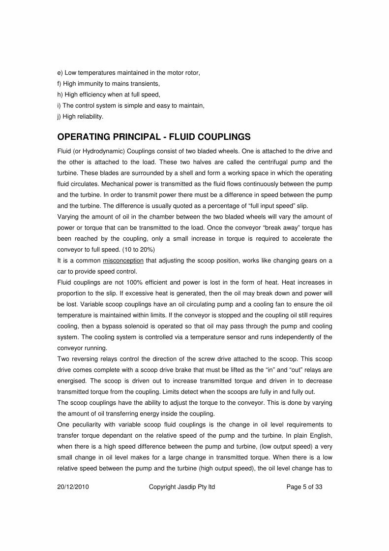
ACCELERATION
SETPOINT
TORQUE
CONTROLPOINT
TORQUEFEEDBACK
CONTROL
OUTPUT
SPEED
FEEDBACK
PID PID
ERRORERROR
ds
dt
ACCELERATION
Figure 10
Acceleration control configuration
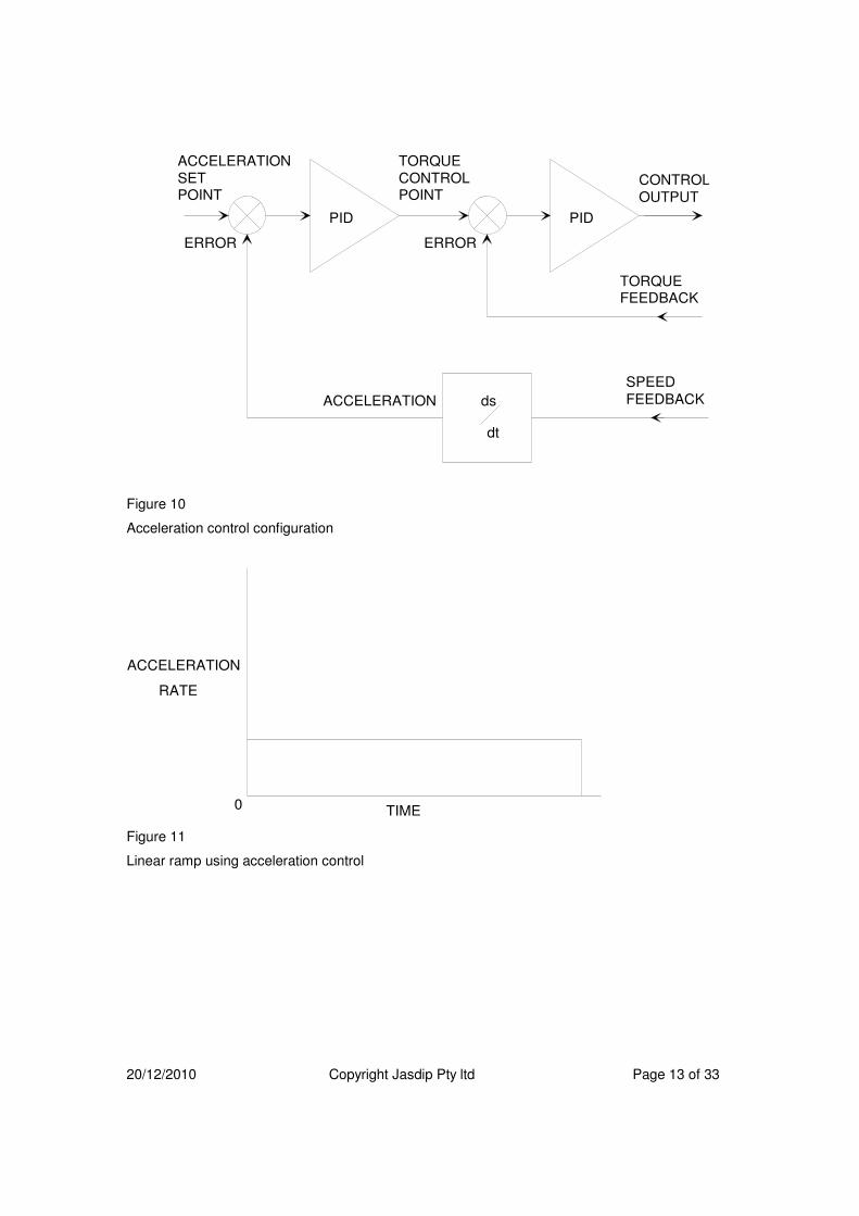
TIME0
RATE
ACCELERATION
Figure 11
Linear ramp using acceleration control

20/12/2010 Copyright Jasdip Pty ltd Page 14 of 33
TIME0
RATE
ACCELERATION
Figure 12
Modified sinusoidal ramp using acceleration control.
TIME0
RATE
ACCELERATION
Figure 13
Acceleration set point control to give an approximate S shaped start.
As can be seen from figures 10 through to 13 acceleration control requires more work in the PID
network but control set points are easier to generate than those used for speed control.
CURRENT RAMP CONTROL
Sometimes there is a situation where only a crude form of speed feedback exists, such as a
proximity detector that only detects one or two pulses per revolution of a pulley. This is not
sufficiently accurate for low speed control. However it can detect the break away point and give a
reasonable indication of the conveyor at full speed. In these circumstances a current ramp can be
used instead of a speed control closed loop system to provide a reasonably linear start. These will

20/12/2010 Copyright Jasdip Pty ltd Page 15 of 33
not be as accurate as speed feedback starts, but still provide a smooth enough start to
dramatically reduce tension waves compared to other methods. The following diagram illustrates
the motor current profile to provide linear starts for a conveyor.
100%
Time (Start Period)
BeltSpeed
0
Lightly LoadedStart Curve
Heavily LoadedStart Curve
100%
Time (Start Period)
MotorCurrent
orTorque
Required
0
Heavy LoadBreakaway
Light Load Running
Heavy Load Running
Conveyor Acceleration Period
Full Speed Reached
Light LoadBreakaway
Starting from a stationary position a conveyor start would take the following steps:-
Perform prestart functions such as Prestart alarms, and brake release.
Start electric motors.
Slowly increase torque from variable torque device until breakaway point is detected.
Read motor current value and store as breakaway current.
Calculate (1.2 x breakaway current) and develop a motor current set point ramp that increments
from breakaway current through to (1.2 x breakaway current) over the desired starting period.

20/12/2010 Copyright Jasdip Pty ltd Page 16 of 33
Vary the torque of the variable torque transmission so that the motor current tracks the ramp until
full speed is reached.
Drive variable torque device to full required torque. The conveyor is now running.
LOAD SHARING
Load sharing is generally not a major issue in fluid drives where there is a soft relationship
between slip speed and torque transmitted. However when motors are driven on two different
pulleys, or it is necessary to take all drives close to their maximum power, it is prudent to
implement some form of load sharing.
When using multiple drives at a drive head or tripper, there is a tendency for one of the drives to
take more of the load than others. This is due to several factors :-
1) Speed variation between the drive drums due to slightly different drum diameters.
JIB PULLEY
SNUBBER
PULLEY
CLEAN SIDE
DRIVE PULLEYDIRTY SIDE
DRIVE PULLEY
Figure 14
Figure 14 shows a typical dual drive configuration. For a dual drive situation one motor is placed
on each drive pulley. Even if both drive drums are machined exactly the same, uneven wear on
drum lagging and a build up of material on the drums will cause slight variations in drum diameter.
A small variation in diameter means that the surface speed will change by 3 times that diameter.
eg. The dirty side drive has a build up of material on the drive pulley of 0.5%. This will cause the
dirty side drive motor to slow down by 1.57%, placing extra load on the dirty side drive. The tighter
the full load % slip specification of the motor, the greater % of the load will be taken by that motor.
If a motor of F.L. 1.0% slip was used it would probably trip on overload.

20/12/2010 Copyright Jasdip Pty ltd Page 17 of 33
2) Belt construction
material carry side (dirty side)
clean side
carcass
(e.g. nylon or
polyester)
PLY BELT CONSTRUCTIONtop
cover
bottom cover
(e.g. nitrile rubber)
(e.g. nitrile rubber)
Figure 15
material carry side (dirty side)
clean side
carcass
(e.g. nylon or
polyester)
SOLID WOVEN BELT CONSTRUCTIONtop
cover
bottom cover
(e.g. PVC)
(e.g. PVC)
Figure 16
Figures 15 and 16 show a cross sectional view of two commonly used belts in underground
mining. The carcass provides the strength of the belt and is typically made from either nylon or
polyester or a combination of both. Nylon is cheaper but has up to 3% stretch when loaded.
Polyester has typically 0.8% stretch when loaded. When driving the belt it is the carcass that
carries the load and tension, therefore when calculating torque around a pulley, it is necessary to
calculate to the centre of the carcass. As can be seen from figure 15 the centre of the driving
force may not be in the centre of the belt. This means that in clean side - dirty side drive situations
there is a smaller diameter of applied torque on the clean side drive to the dirty side drive. This
imbalance contributes to unequal load sharing by the drives.
3) Wear
Under normal use the top cover of a belt will chip with the impact of material and the bottom cover
will scrub away as it is the face in contact with the rollers. This wear is often at an uneven rate and
can effect the drive diameter of the drives at the drive head. Lagging on the drive drums will also
wear away and usually at a different rate for each of the driving pulleys. These wear factors all
influence the load sharing of the driving pulleys no matter how well matched they were when
installed.

20/12/2010 Copyright Jasdip Pty ltd Page 18 of 33
4) Power Imbalance
When three drives are installed, two motors are connected to one drive pulley and a single motor
is connected to the other. If the two pulleys are of matched diameter and the pull of the belting is
symmetrical, then the two motors on the one pulley will have to do half the work of the third.
Load sharing between multiple drives can be achieved in one of three methods using wet
clutches. In these next descriptions the term 'lock-up' will be used. This in fact does not mean
that the clutch is actually locked, as in the case of placing a pin through the plates but means
applying a pressure to the plates that transfers sufficient torque under normal running conditions
not to slip. This pressure should not be so great as to disallow the clutch to slip when and
abnormal condition, such as a jammed boot, occurs. The clutch can then act as a safety release,
preventing further damage to the conveyor.
In the past clutch pressure has been set too high in multiple drive situations. The uneven load
share has either caused slip on the belt or slip in the clutch. Slip on the belt has caused excessive
wear on the slipping pulley. Slip in the clutch, at a much higher torque than desired, will hammer
indentations into the clutch drive spline.
LOAD SHARE METHOD 1
Locked up drives with pressure relief. In this situation both clutches use controlled pressure during
the ramping stage until full belt speed in reached. Once at full belt speed the drive drawing least
current is driven to lockup with sufficient pressure to transmit approximately 130% of full load
motor current. The drive drawing the most current during normal running is locked up with
sufficient pressure to transmit 110% of full load motor current. Once the high current drive draws
110% full load current it's clutch will slip transferring some extra load back to the other drive for a
short period. As the heavier loaded drive is running slightly faster than the lightly loaded one it will
gradually increase it's share of the load over a period of time until it slips again. The rate of load
share increase is dependant upon the mis-match in the speed of the drives.

20/12/2010 Copyright Jasdip Pty ltd Page 19 of 33
100%
TIME0
MOTORCURRENT
FASTERDRIVE
SLOWERDRIVE
SLIP POINT
Figure 17
The slip point of the faster drive may of course be set lower than 110% if required, however care
should be taken to ensure there is sufficient pressure to start the conveyor.
The advantages of the method illustrated in figure 17 are :-
1) It is simple to implement.
2) Requires no change to PID tuning as conveyor conditions change.
3) Only slips the clutch for small periods of time, keeping heating and clutch wear to a minimum.
4) The drive pulleys are machined and lagged the same and therefore inter-changeable.
It's disadvantage is slight unevenness in current between motors. Although this is not harmful to
the motors on an installation that is required to use all of the installed power, motor overloads may
occur at peak load periods.
LOAD SHARE METHOD 2
Locked up drives with pressure relief and controlled pressure on the high current drive. In this
situation both clutches use controlled pressure during the ramping stage until full belt speed in
reached. Once at full belt speed the drive drawing least current is driven to lockup with sufficient
pressure to transmit approximately 130% of full load motor current. The drive drawing the most
current then has its torque or applied pressure value gradually decreased until it is drawing the
same current as the lockup up drive. A slow algorithm then adjusts the output to the non-locked
device to follow the locked devices current. The algorithm is a simple compare and then either
increment or decrement the output to the slipping drive based on the error. The routine would be
run on a regular cycle of 0.5 secs or so.
The advantages of the method are :-
1) It is simple to implement.
2) Requires no change to PID tuning as conveyor conditions change.
3) Only slips tone clutch slightly, keeping heating and clutch wear to a minimum.

20/12/2010 Copyright Jasdip Pty ltd Page 20 of 33
4) The drive pulleys are machined and lagged the same and therefore inter-changeable.
It's disadvantages are:-
1) Care must be taken in developing of the algorithm. Clamps must be applied to outputs to
ensure roll-over cannot occur.
2) During the life of a conveyor, pulley wear can swap which drive will draw the most current.
3) If the current draw is close, the drive drawing the most current can be dependant on conveyor
load.
LOAD SHARE METHOD 3
Single drive locked others slipping. This method requires the use of different diameter pulleys or
different gearbox ratios to give a speed differential between one drive and the others.
SNUBBER
PULLEY
CLEAN SIDE
DRIVE PULLEYDIRTY SIDE
DRIVE PULLEY
LARGER DIAMETER
PULLEY
CLUTCH
SLIPPING
@ 3 to4%
Figure 18
Figure 18 shows how a larger diameter pulley is used on one of the drive drums to provide a
permanent slip at 3 to 4% of full speed on the clutch fitted to that pulley. The smaller diameter
pulley is 'locked up' and controls the speed of the conveyor. The larger pulley's control is a slave
of the locked up pulley's motor current. This arrangement is shown in figure 19 below.

20/12/2010 Copyright Jasdip Pty ltd Page 21 of 33
PID
ERROR
SMALL PULLEYCONTROL OUTPUTLOCK UP
PRESSURESET POINT
SMALL PULLEYTORQUE FEEDBACK
LARGE PULLEYTORQUE FEEDBACK
LARGE PULLEYCONTROL OUTPUT
figure 19
In figure 19 the torque requested by the large pulley is a direct slave of the torque feedback signal
from the small pulley. The PID controlling this slaving operation should be gentle in action to
prevent current hunting between the two drive rollers.
The actual pulley to lock and the one to slip will vary from drive-head to drive-head depending on
the pulley configuration, however the control functionality will remain the same. Pulley diameter
size changes may also be achieved with the thickness of lagging alone.
The advantages of this configuration are :-
1) Equal sharing of motor currents under all conditions so that maximum installed power may be
utilised.
2) Tuning requires little attention as conveyor conditions change.
The disadvantages of this configuration are :-
1) One clutch is permanently slipping, generating more heat and wear than the locked up unit.
2) Different pulley sizes mean they are not interchangeable and care must be taken when
relocating the drive-head.

20/12/2010 Copyright Jasdip Pty ltd Page 22 of 33
LOAD SHARE METHOD 4
All drives slipping.
In this method no drives are 'locked up' with the system being controlled at a few percent under
full speed. All pulley diameters are the same size with variations due to wear and belt torque
radius being adjusted for with slight variations in clutch slip speed.
There are two load share methods used with this technique with only slight differences in reaction
time between them.
SPEED
SET
POINT
TORQUE
CONTROL
POINT
TORQUE 1
FEEDBACK
CONTROL 1
OUTPUT
SPEED
FEEDBACK
PID PID
ERRORERROR
TORQUE 2
FEEDBACK
CONTROL 2
OUTPUT
PID
ERROR
98%
figure 20
In figure 20 the speed PID provides a torque set point for all drives. As load changes occur both
motors are given the same signal to change torque. This allows any drive to removed or added
without the need for master slave operation. If any drive is removed, then there need be no
changes to the control system apart from increasing the speed PID gain and turning off the
appropriate motor.

20/12/2010 Copyright Jasdip Pty ltd Page 23 of 33
SPEED
SET
POINT
TORQUE
CONTROL
POINT
TORQUE 1
FEEDBACK
CONTROL 1
OUTPUT
SPEED
FEEDBACK
PID PID
ERRORERROR
TORQUE 2
FEEDBACK
CONTROL 2
OUTPUT
PID
ERROR
98%
MASTER
SLAVE
figure 21
In figure 21 the speed PID supplies the torque set point for the master drive and all other drives
are slaved off the feedback from the master drive. This means that the master drive must change
value before other drives will change and the master drive must be left when excess drives are
removed or the control code re-written for a new master.
The advantages of this configuration are :-
1) All pulleys and gear boxes are the same diameter and ratio.
2) Even motor current sharing allowing the use of maximum installed power.
The disadvantages of this configuration are :-
1) All clutches in permanent slip with maximum losses due to heating. It should be noted here that
although a theoretical 1% slip is achievable, it more practical to hold 2% slip and experience has
shown that as belt and pulleys wear unevenly, and material builds on pulleys, 3 or even 4% slip
speed set points may be required to maintain load sharing.

20/12/2010 Copyright Jasdip Pty ltd Page 24 of 33
2) It is the most complex of the control systems used and will require tuning changes as the
conveyor conditions change.
3) Where this system has been implemented in clutch systems, lockup and the consequent loss
of load sharing has occurred on a regular enough basis for configuration to be change out for
method 2.
LOAD SHARE METHOD 5 –
SINGLE DRIVE ADJUSTMENT DURING START
This technique can be usd where integer math control is implemented and provides a very
accurate method of load share. At the end of the calculation of error between the desired
acceleration or speed control set point and the actual feedback value, an error value is created
that would normally be used to adjust the output of all control values. Instead of adjusting all
control values, if an increase is required, the lowest of the drives is increased. If a decrease is
required the highest of the drives is decreased. This method provides very accurate load sharing
despite verying external influences such as pulley diameters and varying oil conditions.
TRIPPER CONTROL
Tripper drives are drive stages that are installed in the middle of the carry strand of conveyors.
They assist in lowering the maximum tensions behind the drive-head by spreading the power
along a conveyor. Further distances may achieved with a single conveyor or cheaper, lower
strength belting may be used as maximum tensions are lowered.
material
TRIPPER
DRIVEDRIVE
HEAD
figure 22
Two types of control have been tried with tripper installations. These are power sharing and
tension control.
Power sharing does not take into consideration unevenly loaded conveyors and has problems with
standing waves between the drives.
Tension control allows each drive to take load according to the needs of the conveyor and
guarantees that belt tensions do not exceed limits. In principle, a tripper drive monitors the tension
in front of it and applies enough torque to keep this tension constant. The maximum tension seen

20/12/2010 Copyright Jasdip Pty ltd Page 25 of 33
in-bye of the drive-head is the total of the energy (tension) required to move the belting and load
between the tripper and drive-head and the tension in front of the tripper drive.
That is the maximum tension at the drive head is the tension in KN in-bye of the tripper, plus the
tension in KN required to haul the empty belt between the tripper and the drive head, plus the
tension inKN required to haul the coal between the tripper and drive head.
By adjusting the tension set point at the tripper on a fully loaded conveyor, appropriate load
share is achieved between drive head and tripper and belt tensions are kept to a minimum.
TENSION
SET
POINT
TORQUE
CONTROL
POINT
TORQUE
FEEDBACK
CONTROL
OUTPUT
TENSION
FEEDBACK
PID PID
ERRORERROR
Figure 23
Figure 23 illustrates the control requirements for tension control using trippers.
TRANSDUCER SELECTION
As with any computer control system, the reliability is often lowered by external field devices. The
information they provide or transmit and their susceptibility to damage makes them the weakest
link in the chain. There are three components crucial to the starting control of conveyors with wet
clutches or fluid drives and these are :-
1) The torque feedback signal.
2) The speed feedback signal
3) The hydraulic pressure control output.
4) Scoop or Drain control arm for fluid couplings.
In a closed loop system if any of these fail, catastrophic results may occur.
20/12/2010 Copyright Jasdip Pty ltd Page 26 of 33
TORQUE FEEDBACK SIGNAL
The motor torque feedback signal can be measured by either a motor power transducer or a
motor current transducer. True motor power is more accurate than motor current for determining
torque (in phase current), but as this is part of the inner control loop, the outer control loop will
adjust this value accordingly. Therefore high levels of accuracy are not required. In general motor
current transducers (ie. CTs and 0-5a to 4-20ma transducers) are more reliable and cost less
than power transducers and are therefore more commonly used. Measurement of a single phase
to the motor is sufficient for both torque control and load sharing. Overload units are best
equipped to protect for phase current imbalances. It should be noted that the torque PID loop is
run at under 0.5 seconds and therefore current or power transducers that are interrogated serially
may not be suitable. However a comparison of the two may be useful for transducer failure.
SPEED FEEDBACK SIGNAL
The speed feedback signal is a critical value and gives most problems with installations. It is worth
spending extra engineering time and money to ensure that is reliable and accurate. It may be
generated by tachometer, encoder or proximity detector. The transducer may monitor either the
speed of the driving pulley or the speed of a freewheeling pulley. In either case the other point will
need to be monitored by the conveyor control system to ensure that drive pulley slip does not
damage the belting. In multiple drive systems each individual drive pulley will require slip
monitoring. Operating range of the units must also be considered as it its important to have a
smooth signal at low speeds. For frequency types, at least 50 Hz at full speed is necessary to give
reasonable results at low speeds.
Tachometers - provide an output voltage or current proportional to speed. Voltage types are
usually a wound armature rotating in a fixed magnet stator and cannot be adjusted except via
voltage divider at the PLC. They require maintenance of brushes and commutator on a periodic
basis. More recently Ringway has designed a 4 to 20ma adjustable electronic tachometer for this
purpose. It is a sealed brass unit using infrared beam technology.
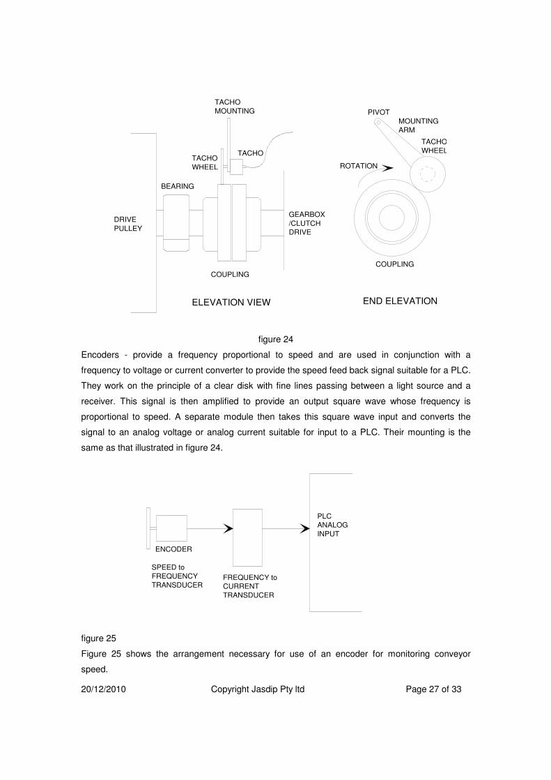
Tachometer Mounting - Below are some typical mounting examples :-
20/12/2010 Copyright Jasdip Pty ltd Page 27 of 33
BEARING
COUPLING
DRIVE
PULLEY
GEARBOX
/CLUTCH
DRIVE
TACHO
MOUNTING
TACHOTACHO
WHEEL
ELEVATION VIEW END ELEVATION
COUPLING
PIVOT
MOUNTING
ARM
TACHO
WHEEL
ROTATION
figure 24
Encoders - provide a frequency proportional to speed and are used in conjunction with a
frequency to voltage or current converter to provide the speed feed back signal suitable for a PLC.
They work on the principle of a clear disk with fine lines passing between a light source and a
receiver. This signal is then amplified to provide an output square wave whose frequency is
proportional to speed. A separate module then takes this square wave input and converts the
signal to an analog voltage or analog current suitable for input to a PLC. Their mounting is the
same as that illustrated in figure 24.
ENCODER
FREQUENCY to
CURRENT
TRANSDUCER
SPEED to
FREQUENCY
TRANSDUCER
PLC
ANALOG
INPUT
figure 25
Figure 25 shows the arrangement necessary for use of an encoder for monitoring conveyor
speed.

20/12/2010 Copyright Jasdip Pty ltd Page 28 of 33
Proximity detectors - when used in conjunction with slotted wheels on rotating shafts, provide a
frequency proportional to speed. Like encoders, they need a frequency to voltage or current
transducer to interface to a PLC.
INDUCTIVE
PROXIMATEY
DETECTOR
SPEED to
FREQUENCY
TRANSDUCERTOOTHED WHEEL
ELEVATION SIDE ELEVATION
FREQUENCY
to CURRENT
TRANSDUCER
PLC
ANALOG
INPUT
Figure 26
The above plate configuration is sometimes subject to plate buckeling due to rough handling. This
gives a surging speed feedback. A more reliable method is shown in the figure below, where the
outer steel rim of a pulley provides the support for the teeth.
Sam
e D
iam
ete
r as
Pulle
y b
efo
re L
ag
gin
g
6.5mm Bolts, Tapped into theend of the pulley skin.
Ring Cut after manufacture to allowfitting around a shaft. Bolted tabs onrear of tooth and front ring to holdback together. Tabs fitted before cutting.
Tabs 1.5 times diameterof proximity sensor
CNC Laser Cut (minimise warping) from 6mm mild steel (8mm would be stiffer)

20/12/2010 Copyright Jasdip Pty ltd Page 29 of 33
HYDRAULIC PRESSURE CONTROL OUTPUT
Control of the clutches are achieved through a hydraulic proportional valve. These valves provide
an output hydraulic pressure that is proportional to current flow through their coils. The current
flow normally lies in the range of 0 to 500ma and 0 to 1.6A. These values are outside the normal
PLC output card's drive ability and so a booster amplifier must be used. It is desirable for the
booster card to have the following features :-
1) Ability for manual control over the full range for commissioning and emergency conditions.
2) Closed loop current control of the drive stage to negate drift due to temperature variations in
the coil.
3) Fast response to change with no built in ramps or time lags. Additional lags make PLC PID
tuning more difficult.
4) Standard 4 to 20ma control signal input.
TYPICAL OPERATING SEQUENCE
The normal starting sequence for a clutch system is as follows :-
1) A sequence start command is given to the conveyor drive-head.
2) The Drive head performs it's pre-start checks and then commands a start to the loop takeup
winch and the clutch control.
3) The clutch system starts it's hydraulic pump and ensures that lubrication is O.K. The winch
starts and applies starting tension to the conveyor.
4) Once the clutch system and the winch system indicate they have completed their pre-start and
there are no fault conditions, the drive head motor start is enabled.
5) The drive-head starts the main motors DOL on no load in an appropriate sequence.
6) Once the drive head motors have started and settled (approx 3secs) a pressure to over come
the springs and just touch the clutch pack plates is applied. A small time delay is used to allow the
applied pressure to fill the thrust piston chamber. The cooling fans are turned on for the duration
of the start.
7) The pressure is now gradually increased drawing more motor current. This stage is called the
torque ramp as the motor torque is increased until the conveyor begins to move.
8) The control system now switches in which ever ramping control is used.
9) Once the conveyor has reached full speed the full speed control is switched in.

20/12/2010 Copyright Jasdip Pty ltd Page 30 of 33
FAULT MONITORING
The following fault conditions must be monitored and stop the conveyor should they occur :-
1) Loss of hydraulic pump. The cooling and lubrication flow will be lost causing damage to the
clutch.
2) Excess oil temperature. Oil that exceeds 100 degrees Celsius looses its lubricating properties
and will permanently damage the clutch.
3) Broken hose or damaged oil seals. A broken hose may be monitored by oil levels dropping in
the reservoir tank, loss of lubrication pressure or the inability to control the clutch properly.
4) Dirty or blocked oil filter. Filters that are blocked will bypass dirt into the system. This will
eventually cause problems in the proportional control valve. Although it is not necessary to stop
the conveyor, the fault should be remedied quickly.
5) Belt slip. Belt slip should be monitored on each driving pulley. Even the smallest amount of slip
will cause heating and damage both belt and pulley lagging and provide a fire hazard.
6) Loss of transducer signals. The loss of motor current, speed or tension feedback will caused an
uncontrolled response by the PID closed loop system. These signals should be monitored and the
conveyor tripped if any are lost or out of range.
OVERCOMMING PID OSCILATION PROBLEMS
CAUSES OF OSCILATION
ELASTICITY
PID algorithms have proven to be a successful control technique over many years. Unfortunately
they have a weakness in that they do not perform well on elastic loads. The problem arises
because as an adjustment to the output is stored as elastic energy in the load. The PID would
have expected to see some feedback change after it modified the output, but this has not
occurred. The PID therefore makes another modification in output , and then another until it sees
a change in feedback. Eventuall the stored elastic energy is released, which then causes an
overshoot of the load value. The PID see this overshoot and compensates by driving the output in
the opposite direction. Because of the elastic nature of the load, the change is again not reflected
in the feedback and so it compensates again. This lag in feedback can cause large oscillations in
the control system. The typical response of the Technician or Engineer is to lower the gain of the
PID so that it does not over re-act. This of course provides a very soft control system where the
result may be erroneous from the set point by a unacceptable value.
LARGE VARIATIONS IN LOAD CONDITIONS
There are variations of control requirements between an empty conveyor and a fully loaded
conveyor. Ratios of around 1:4 are found on flat conveyor systems, while ratios as high as 1:15
are common on high lift conveyors. A PID control algorithm makes a certain amount of output

20/12/2010 Copyright Jasdip Pty ltd Page 31 of 33
change based on a certain error between the required setpoint and the actual feedback. The
actual value is governed by the system gain, which is determined during commissioning.
However, the response to an error should be less for an empty conveyor and more for a fully
loaded conveyor. The bigger the difference between no load and full load, the harder it is to find
the right compromise for the tuning.
PROCESS DISTURBANCES FROM ANCILIARY EQUIPMENT
In certain installations, gravity devices are unsuitable for tensioning conveyors. In these
circumstances electro/mechanical devices take up the slack in the conveyor caused by elastic
stretch in the belting during starting period and load changes. Generally devices that provide
proportional speed to tension change control, do not cause problems. However devices that
provide a fixed speed tension adjustment, pulse in operation and can cause problems in the
closed loop circuitry. This pulsed response to error causes a pulse in the speed control feedback
signal, for which the PID algorithm can over respond.
NON LINEAR RESPONSE FROM TRANSMISSION SYSTEM
BOSS clutches and certain Fluid couplings have non-linear response to control over their entire
operating range. With a BOSS coupling the required pressure to maintain torque begins roll off as
the relative plate speed between input and output drops below 10% of full slip speed. Many Fluid
couplings have non-linear scoop position to transmitted torque relationships. These are generally
represented in graphs supplied by the manufacturer.
TECHNIQUES FOR LIMITING CONTROL SYSTEM OSCILATIONS
INPUT ERROR LIMITING
This technique involves limiting the size of the error fed to the PID algorithm by adjusting the set
point closer to the feedback value if the error becomes too great. This technique is popular with
drive head control where unforeseen outside influences, such as jammed belting, erratic tension
control or changing load conditions. (e.g. a heavy block of material passing over an undulating
horizontal profile)
RATE OF CHANGE LIMITING
In this case a rate change limiter is fitted between the output of the PID and the actual output to
the control value. In practice it is an integrator, but implementation in PLC code can be as simple
as a periodic fixed add or subtract to increase or decrease the output control based on the result
of the PID and the current value of the output. This is done in small steps over a period of time,
rather than a single large step. This technique is popular with tripper drive control.
VARIABLE PID GAIN CONTROL
Either the applied torque or applied power from the drive motors is used to modify the gain of the
PID. A proportionally higher gain is used for heavy loads and a proportionally lower gain is used

20/12/2010 Copyright Jasdip Pty ltd Page 32 of 33
for lighter loads. This technique is popular when there is a large differential between no load and
full load.
INTEGER MATH CONTROL
This method uses a much simpler algorithm than a PID. On a regular time tick, usually one or two
seconds, the actual speed is compared to the required speed. An error value is calculated and a
portion of this error added to the output control. The portion of the error that is added provides a
gain control, while the rate of sample provides an integral control. This technique provides a softer
response to error than standard PID control.
LOOKUP TABLE LINEARISATION
This technique provides a simple method for overcoming non-linear relationships between control
signal and actual applied torque. It usually requires passing the result of the PID algorithm result
through a lookup table modifier before it is passed to the output controller. This might be applied
pressure in a BOSS control circuit or a dip compensation for scoop position in a fluid coupling.
In very difficult control systems, a lookup table that converts motor current to applied motor torque
can remove offsets that create problems for the control system.
SWEET SPOT LIMITING
In this method, the output of the speed or acceleration PID is clamped to reasonable limits based
on typical start knowledge. For example once a conveyor is fully stretched and moving at say 10%
to 15% speed, you know that you will not require less than the current value of motor current to
accelerate the conveyor to full speed. This becomes the minimum output of the speed or
acceleration PID during the ramp. You also know that you will not need more than 1.3 to 1.35
times this motor current value to accelerate to full speed. This becomes the maximum output of
the speed or acceleration PID during the ramp. This method also becomes a safety relief if a
speed feedback transducer fails during the ramp.
Clamping can be achieved by directly overriding the output stage of the PID or switching the PID
to manual for a period will ever the output is outside the sweet spot limits and holding either the
minimum or maximum value as required,