Embed Size (px)
DESCRIPTION
DESIGN OF STARTER GENERATOR
Citation preview
US007508086B2
(12) United States Patent Huang et al.
US 7,508,086 B2 Mar. 24, 2009
(10) Patent N0.: (45) Date of Patent:
(54)
(75)
(73)
(*)
(21)
(22)
(65)
(60)
(51)
(52)
(58)
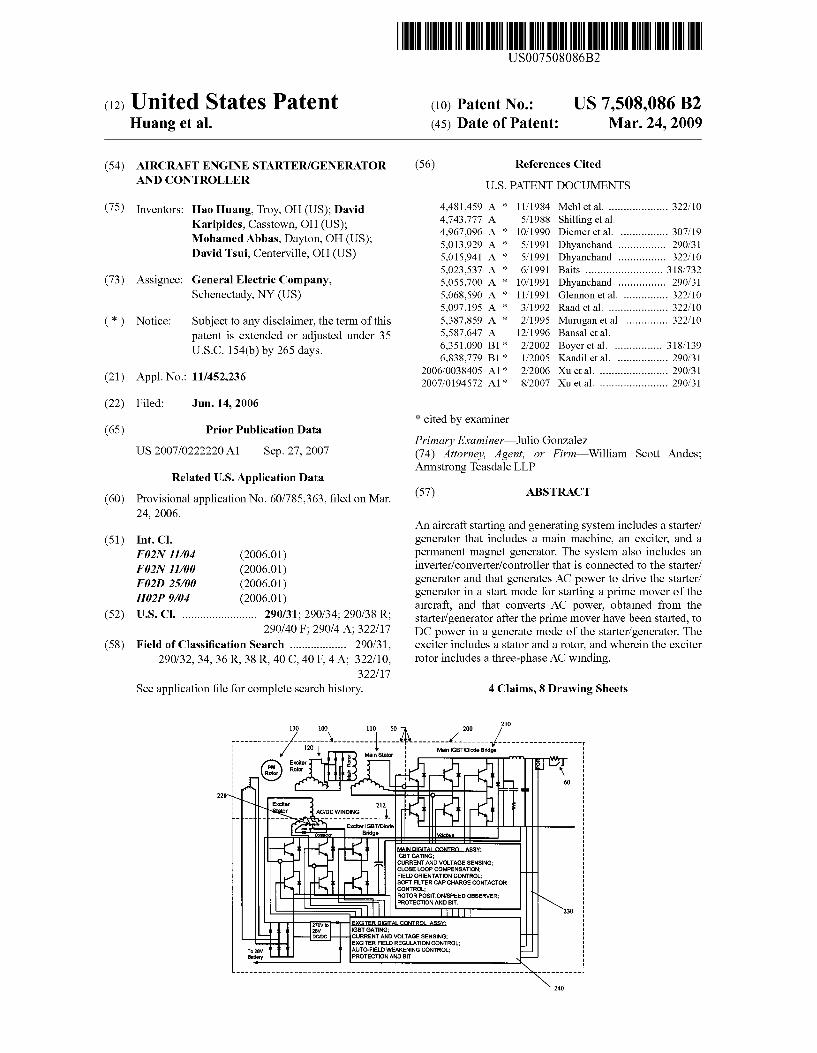
AIRCRAFT ENGINE STARTER/GENERATOR AND CONTROLLER
Inventors: Hao Huang, Troy, OH (US); David Karipides, CasstoWn, OH (US); Mohamed Abbas, Dayton, OH (US); David Tsui, Centerville, OH (US)
Assignee: General Electric Company, Schenectady, NY (US)
Notice: Subject to any disclaimer, the term of this patent is extended or adjusted under 35 USC 154(b) by 265 days.
Appl. No.: 11/452,236
Filed: Jun. 14, 2006
Prior Publication Data
US 2007/0222220 A1 Sep. 27, 2007
Related US. Application Data
Provisional application No. 60/785,363, ?led on Mar. 24, 2006.
Int. Cl.
F 02N 11/04 (2006.01) F 02N 11/00 (2006.01) F 02D 25/00 (2006.01) H02P 9/04 (2006.01) US. Cl. ....................... .. 290/31; 290/34; 290/38 R;
290/40 F; 290/4 A; 322/17 Field of Classi?cation Search ................. .. 290/31,
290/32, 34, 36 R, 38 R, 40 C, 40 F, 4 A; 322/10, 322/ 17
See application ?le for complete search history.
(56) References Cited
U.S. PATENT DOCUMENTS
4,481,459 A * 11/1984 Mehlet a1. .................. .. 322/10
4,743,777 A 5/1988 Shilling et a1. 4,967,096 A * 10/1990 Diemer et a1. .............. .. 307/19
5,013,929 A * 5/1991 Dhyanchand 290/31 5,015,941 A * 5/1991 Dhyanchand .............. .. 322/10
5,023,537 A * 6/1991 Baits ........................ .. 318/732
5,055,700 A * 10/1991 Dhyanchand . . 290/31
5,068,590 A * 11/1991 Glennon et a1. 322/10 5,097,195 A * 3/1992 Raad et a1. .................. .. 322/10
5,387,859 A * 2/1995 Mur'ugan et a1. ............ .. 322/10
5,587,647 A 12/1996 Bansal et a1. 6,351,090 B1* 2/2002 Boyer et a1. .............. .. 318/139
6,838,779 B1 * 1/2005 Kandil et a1. . . . . . . . . .. 290/31
2006/0038405 A1* 2/2006 Xu et a1. . . . . . . . . . . . .. 290/31
2007/0194572 A1* 8/2007 Xu et a1. ..................... .. 290/31
* cited by examiner
Primary Examinerilulio Gonzalez (74) Attorney, Agent, or FirmiWilliam Scott Andes; Armstrong Teasdale LLP
(57) ABSTRACT
An aircraft starting and generating system includes a starter/ generator that includes a main machine, an exciter, and a permanent magnet generator. The system also includes an inverter/converter/controller that is connected to the starter/ generator and that generates AC poWer to drive the starter/ generator in a start mode for starting a prime mover of the aircraft, and that converts AC poWer, obtained from the starter/ generator after the prime mover have been started, to DC poWer in a generate mode of the starter/ generator. The exciter includes a stator and a rotor, and Wherein the exciter rotor includes a three-phase AC Winding.
4 Claims, 8 Drawing Sheets
Main lGBT/Dlode BrIdge
\ Exciter '11 2 _
7 AC/DC WINDING l
_ ExcIter IGBTIDIoda Bridge
II . r I r A :
IGBT GATING; CURRENT AND VOLTAGE SENSING: CLOSE LOOP COMPENSATION; FIELD ORIENTATION CONTROL; SOFT FILTER CAP CHARGE CONTACTOR CONTROL: ROTOR POSITION/SPEED OBSERVER; \ PROTECTION AND BIT. \
To zsv Battery
— CURRENT AND VOLTAGE SENSING; _
EXCITER FIELD REGULATION CONTROL; AUTO-FIELD WEAKENING CONTROL: PROTECTION AND BIT,
US. Patent Mar. 24, 2009 Sheet 1 of8 US 7,508,086 B2
‘212 200 210
EXT
Ac DC/AC '00 30 AC [\I 112 ! oc/oc / \ /
U Exciter 3/ 124 C Main D @b ____—-—— H6 118 114
i: C m, *" N“ / Recti?cation
PMG E .t otor 122 XCI er T
Rotor 1 m
30 '20 T Three Core Synchronous Design
Figure 1.
US. Patent Mar. 24, 2009 Sheet 3 of8 US 7,508,086 B2
S H b a v
HO
I H
h 1
W e
2 a r.
1.1 U u 2 em .Wa
,ms F
nu .W H:
0 My 5
HIV a. a
r 0M WWW SVP
0
3 _
1 _ n m
r
u; __ _ 2
.HH _ \
“mm _ “ \"nc " n 01; _ _ 4.6M.“ " _
2 Emmi; "
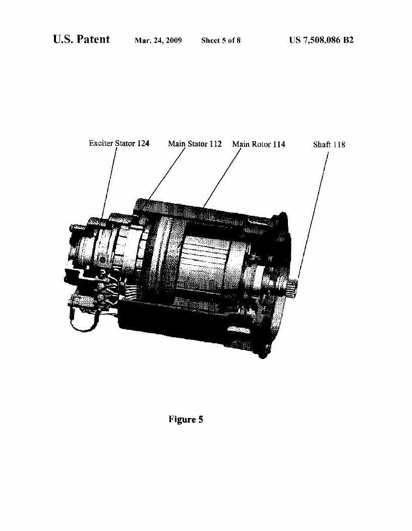
US. Patent Mar. 24, 2009 Sheet 5 of8 US 7,508,086 B2
Exciter Stator 124 Main Stator 112 Main Rotor 114 Sha? 118
Figure 5
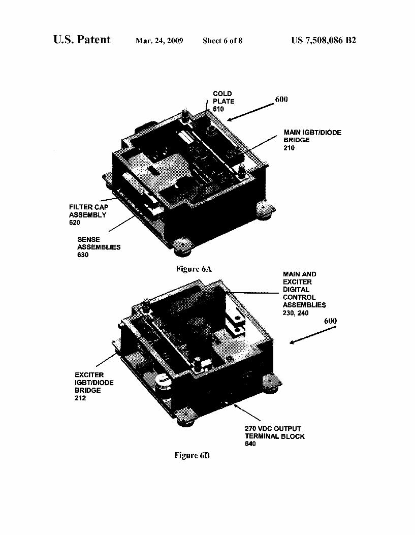
US. Patent Mar. 24, 2009 Sheet 6 of8 US 7,508,086 B2
PLATE 600
MAIN lGBT/DIODE BRIDGE 210
FILTER CAP ASSEMBLY 620
SENSE ASSEMBLIES 630
Flgu re 6A MAIN AND EXCITER DIGITAL CONTROL ASSEMBLIES 230, 240
600
EXCITER IGBTIDIODE BRIDGE 212
270 VDC OUTPUT TERMINAL BLOCK 640
Figure 6B
US. Patent Mar. 24, 2009 Sheet 7 of8 US 7,508,086 B2
Tek _n_ I Acq Complete M Pos: 4211mm CUHSUH
Type
1- —
4+ . _
Source W
Delta 540m‘?
f _ ' ' V. . [H5031
EH1 1.000" EH2 1.13m’ Mw?ms EH5 123100" EH4 5.000 a-nm-nsm-as <1£|Hz
Figure 7.
US. Patent Mar. 24, 2009 Sheet 8 of8 US 7,508,086 B2
f q —axis A
Regenerate Mode or Motoring Mode Xaa'If Generate Mode
axis
A — axis
Figure 8.
US 7,508,086 B2 1
AIRCRAFT ENGINE STARTER/GENERATOR AND CONTROLLER
FIELD OF THE INVENTION
The invention relates generally to a combination of a bidi rectional energy conversion brushless electric rotating device that converts electrical energy to mechanical energy in start mode and mechanical energy to electrical energy in generate mode. In particular, the invention relates to a high poWer density aircraft engine starting and poWer generating system, that includes a three electric machine set, a Starter/ Generator (S/G), and an IGBT based and digitally controlled device, referred to herein as an Inverter/ Converter/ Controller (ICC). Furthermore, the invention relates to elimination of the rotor position sensor of a Wound ?eld synchronous machine based S/G, resulting in a sensorless-controlled S/ G and ICC system.
DESCRIPTION OF THE RELATED ART
There currently exist starter generator systems for aircraft, Which are used to both start an aircraft engine, and to utiliZe the aircraft engine after it has started in a generate mode, to thereby provide electrical energy to poWer systems on the aircraft. For example, US. Pat. No. 4,743,777, issued to William Shilling et al., describes a starter generator system With tWo stator exciter Windings, and Which includes a vari able voltage, variable frequency poWer converter that is alter nately connected to drive an dynamoelectric machine as a starting motor or to receive poWer from the machine during generator operation. US. Pat. No. 5,587,647, issued to Madan Bansal et al., describes a dual output, synchronous induction starting/generating system. The Bansal system includes a synchronous generator and an induction motor/ generator mutually coupled to a shaft that is driven to an external prime mover, such as an aircraft engine. The Bansal system also includes a recti?er/inverter that alloWs bi-direc tional poWer How to effectuate both poWer generation as Well as electric start of the aircraft engine.
While the prior art systems described above are useful in starting an aircraft engine and in generating poWer from the aircraft engine once the engine has started, it is desirable to come up With a system that has at least one of a higher poWer density, a higher e?iciency, and a higher dynamic perfor mance, in either or both a start mode and a generate mode.
SUMMARY OF THE INVENTION
According to at least one aspect of the invention, there is an aircraft engine starter/ generator system that includes a Starter/Generator (S/G), and an Inverter/Converter/Control (ICC), With higher poWer density, higher e?iciency, and higher dynamic performance in both start mode and generate mode, as compared to the conventional systems in the ?eld.
The S/ G includes three electric machines: a main machine, an exciter, and a Permanent Magnet Generator (PMG). The ICC, Which can be an IGBT based inverter/converter/control ler and Which is a digitally controlled, bidirectional electronic device, is connected to the input/ output of the stator Winding of the main machine of the S/G. The electronic device gen erates AC poWer to drive the S/ G in start mode and converts the AC poWer to the DC poWer requested on the aircraft in generate mode. A ?rst embodiment includes at least tWo aspects of a S/G
system that result in lighter Weight and superior performance of the overall system. The ?rst aspect is a dual functional exciter stator that contains a Winding Working conjunction
20
25
30
35
40
45
50
55
60
65
2 ally With a contactor located in the ICC. During start mode, the Winding is con?gured into an AC three phase Winding by the contactor, and during generate mode, the Winding is con ?gured into a single DC Winding by the same contactor. Without adding any appreciable siZe and Weight on the machine, the dual AD and DC functional Winding satisfying the needs for start mode and generate mode respectively. The second aspect is the elimination of the conventional mechani cal position sensor for commutation of the poWer electronic sWitches in both start mode and generator mode. This achieves noticeable siZe and Weight reduction of the S/G. A second embodiment is directed to the start mode of the
S/G system, and includes ?ve aspects that act to achieve better torque density of the S/G in start mode, as compared to the conventional approaches in the ?eld. The ?rst aspect is the three phase AC Winding of the exciter stator con?gured and controlled in the braking mode of the induction machine. RealiZation of a Zero speed sensorless approach corresponds to the second aspect related of this embodiment. The third aspect is an auto-?eld Weakening mechanism developed to keep the inverter Well Within the Pulse Width Modulation (PWM) region and retain effective current regulations throughout the entire speed range in start mode. The fourth aspect is the combining of auto-?eld Weakening With a near unity poWer factor control scheme, in order to accomplish higher poWer density at high speed While the inverter voltage is saturated. The ?fth aspect is a vector control scheme in conjunction With a negative d-axis current pro?le that oppo sitely aligns to the ?eld current of the main machine to gen erate maximum reluctance torque to overcome the torque limitation caused by the magnetic saturation. The approach increases the torque density of the S/G as compared to con ventional systems. A third embodiment is directed to the generate mode of the
S/G system, and includes four aspects. The ?rst aspect is related to the inactive and active recti?cation con?gurability. Controlled by the exciter converter digital control assembly 240 and the main converter digital control assembly 230, the main IGBT/ Diode Bridge can become an inactive recti?er or an active recti?er, depending upon the application. The sec ond aspect is directed to a control of the IGBT converter that combines auto-?eld modi?cation and over-modulation to achieve optimum ef?ciency of the IGBT generate mode operation. The third aspect is the providing of an IGBT com mutation approach during generate mode. The IGBTs’ com mutation is based on a voltage mode sensorless, Which is a similar sensorless approach used in start mode. The fourth aspect is directed to accomplishing regeneration in absorbing excessive energy on the DC bus into the machine While regu lating the bus voltage simultaneously.
BRIEF DESCRIPTION OF THE DRAWINGS
The foregoing advantages and features of the invention Will become apparent upon reference to the folloWing detailed description and the accompanying draWings, of Which:
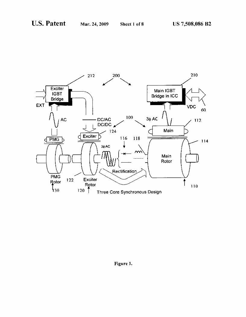
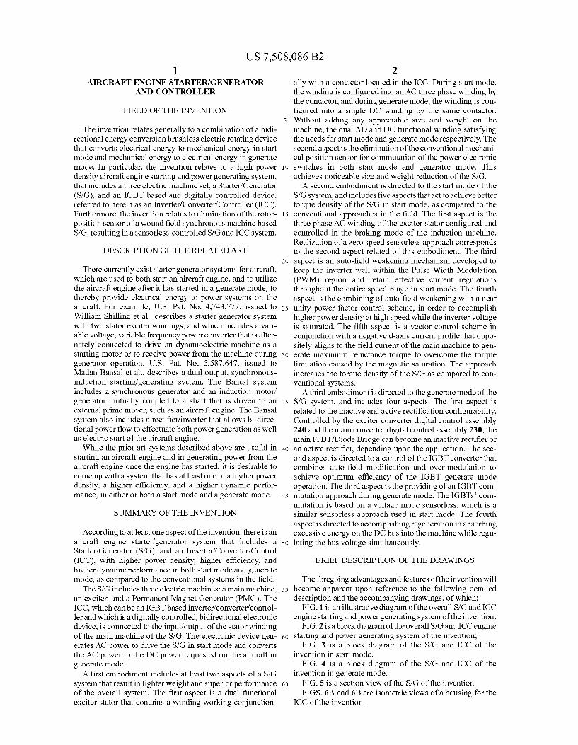
FIG. 1 is an illustrative diagram of the overall S/ G and ICC engine starting and poWer generating system of the invention;
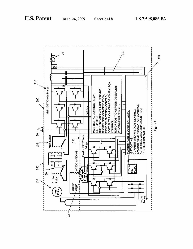
FIG. 2 is a block diagram of the overall S/G and ICC engine starting and poWer generating system of the invention;
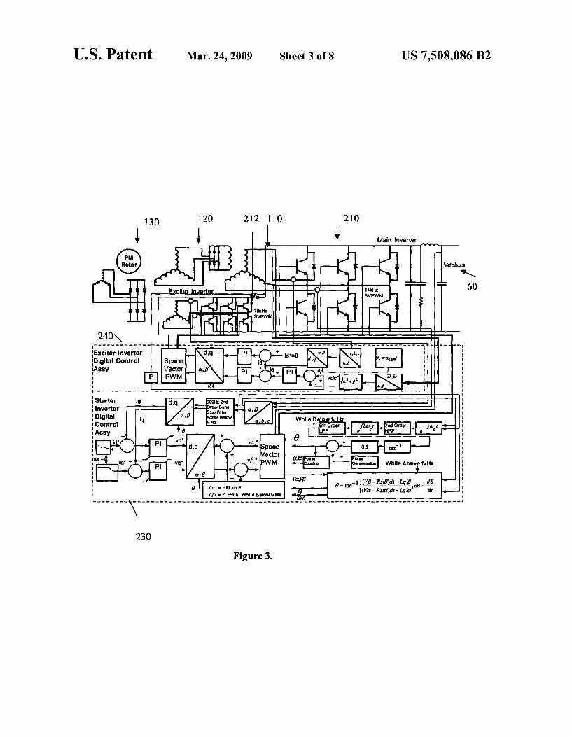
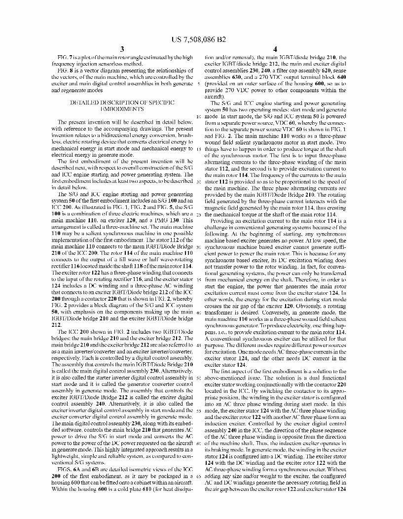
FIG. 3 is a block diagram of the S/G and ICC of the invention in start mode.
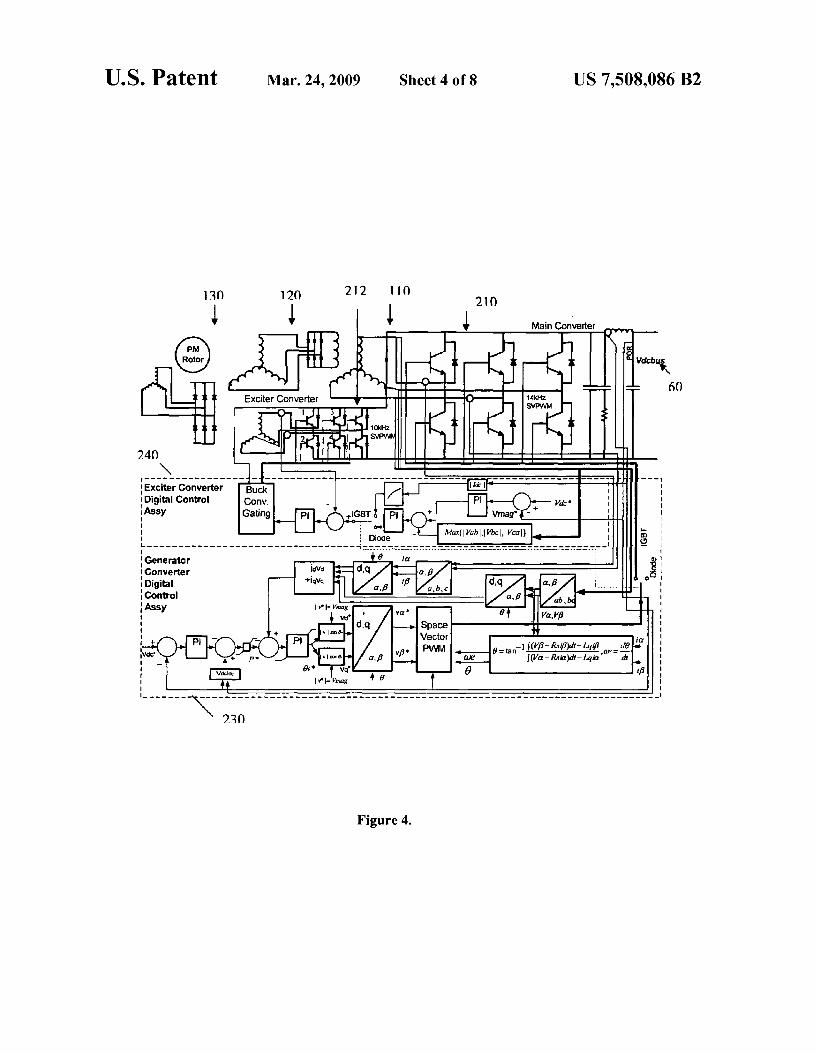
FIG. 4 is a block diagram of the S/G and ICC of the invention in generate mode.
FIG. 5 is a section vieW of the S/G of the invention. FIGS. 6A and 6B are isometric vieWs of a housing for the
ICC of the invention.
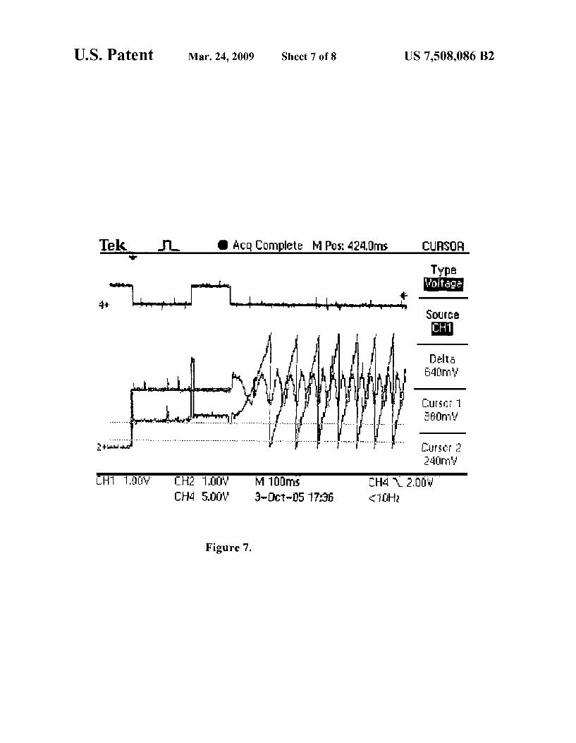
US 7,508,086 B2 3
FIG. 7 is a plot of the main rotor angle estimated by the high frequency injection sensorless method.
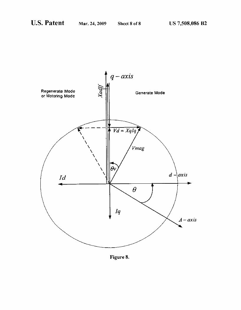
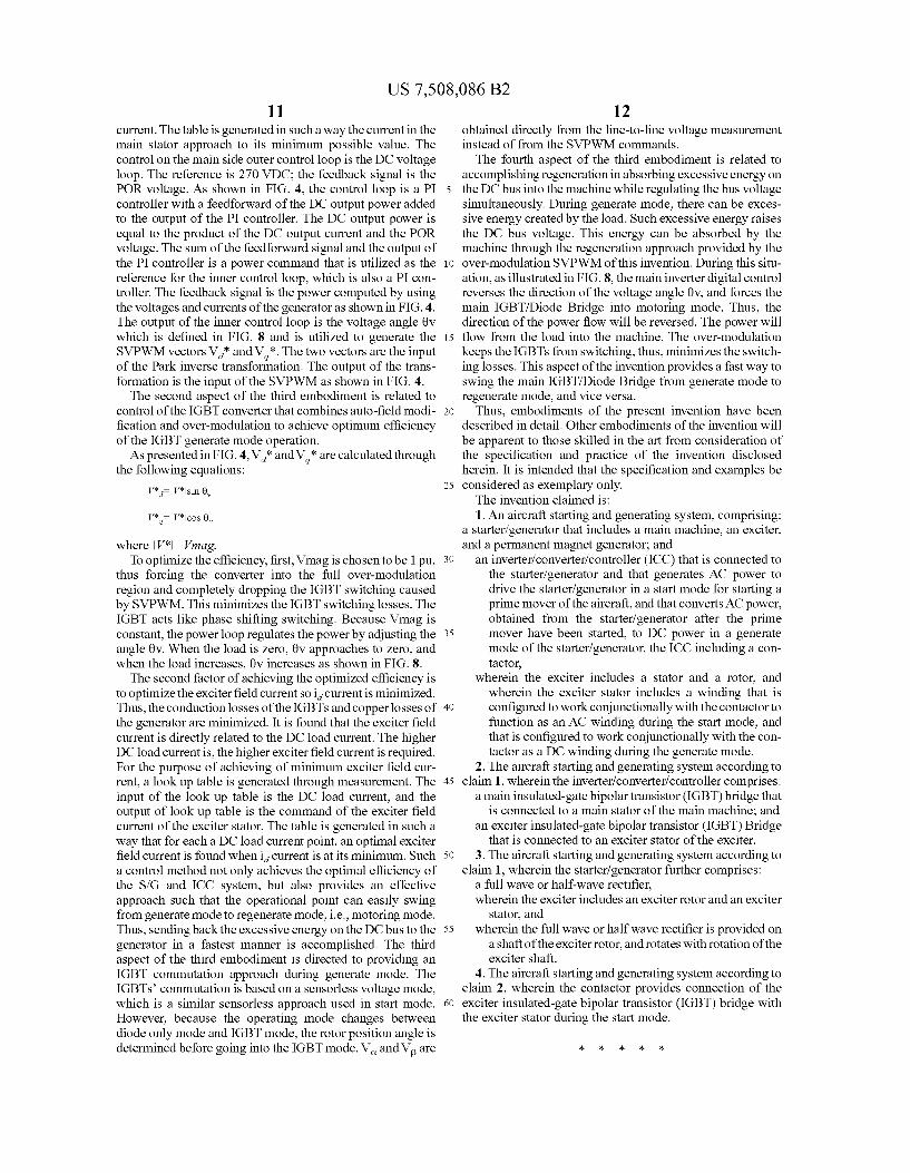
FIG. 8 is a vector diagram presenting the relationships of the vectors, of the main machine, Which are controlled by the exciter and main digital control assemblies in both generate and regenerate modes.
DETAILED DESCRIPTION OF SPECIFIC EMBODIMENTS
The present invention Will be described in detail beloW, With reference to the accompanying draWings. The present invention relates to a bidirectional energy conversion, brush less, electric rotating device that converts electrical energy to mechanical energy in start mode and mechanical energy to electrical energy in generate mode.
The ?rst embodiment of the present invention Will be described next, With respect to overall construction of the S/G and ICC engine starting and poWer generating system. The ?rst embodiment includes at least tWo aspects, to be described in detail beloW.
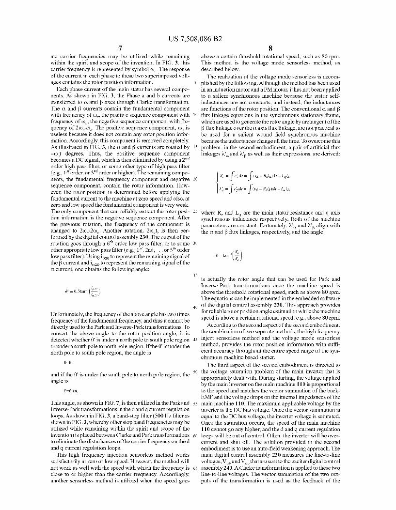
The S/ G and ICC engine starting and poWer generating system 50 of the ?rst embodiment includes an S/G 100 and an ICC 200. As illustrated in FIG. 1, FIG. 2 and FIG. 5, the S/G 100 is a combination of three electric machines, Which are a main machine 110, an exciter 120, and a PMG 130. This arrangement is called a three-machine set. The main machine 110 may be a salient synchronous machine in one possible implementation of the ?rst embodiment. The stator 1 12 of the main machine 110 connects to the main IGBT/Diode Bridge 210 of the ICC 200. The rotor 114 of the main machine 110 connects to the output of a ?ll Wave or half Wave-rotating recti?er 116 located inside the shaft 118 of the main rotor 114. The exciter rotor 122 has a three-phase Winding that connects to the input of the rotating recti?er 116, and the exciter stator 124 includes a DC Winding and a three-phase AC Winding that connects to an exciter IGBT/Diode bridge 212 of the ICC 200 through a contactor 220 that is shoWn in FIG. 2, Whereby FIG. 2 provides a block diagram of the S/G and ICC system 50, With emphasis on the components making up the main IGBT/Diode bridge 210 and the exciter IGBT/Diode bridge 212.
The ICC 200 shoWn in FIG. 2 includes tWo IGBT/Diode bridges: the main bridge 210 and the exciter bridge 212. The main bridge 210 and the exciter bridge 212 are also referred to as a main inverter/ converter and an exciter inverter/ converter, respectively. Each is controlled by a digital control assembly. The assembly that controls the main IGBT/ Diode Bridge 210 is called the main digital control assembly 230. Alternatively, it is also called the starter inverter digital control assembly in start mode and it is called the generator converter control assembly in generate mode. The assembly that controls the exciter IGBT/Diode Bridge 212 is called the exciter digital control assembly 240. Alternatively, it is also called the exciter inverter digital control assembly in start mode and the exciter converter digital control assembly in generate mode. The main digital control assembly 230, along With its embed ded softWare, controls the main bridge 210 that generates AC poWer to drive the S/ G in start mode and converts the AC poWer to the poWer of the DC poWer requested on the aircraft in generate mode. This highly integrated approach results in a lightWeight, simple and reliable system, as compared to con ventional S/G systems.
FIGS. 6A and 6B are detailed isometric vieWs of the ICC 200 of the ?rst embodiment, as it may be packaged in a housing 600 that can be ?tted onto a cabinet Within an aircraft. Within the housing 600 is a cold plate 610 (for heat dissipa
20
25
30
35
40
45
50
55
60
65
4 tion and/or removal), the main IGBT/diode bridge 210, the exciter IGBT/diode bridge 212, the main and exciter digital control assemblies 230, 240, a ?lter cap assembly 620, sense assemblies 630, and a 270 VDC output terminal block 640 (provided on an outer surface of the housing 600, so as to provide 270 VDC poWer to other components Within the aircraft). The S/G and ICC engine starting and poWer generating
system 50 has tWo operating modes: start mode and generate mode. In start mode, the S/G and ICC system 50 is poWered from a separate poWer source, VDC 60, Whereby the connec tion to the separate poWer source VDC 60 is shoWn in FIG. 1 and FIG. 2. The main machine 110 Works as a three-phase Wound ?eld salient synchronous motor in start mode. TWo things have to happen in order to produce torque at the shaft of the synchronous motor. The ?rst is to input three-phase alternating currents to the three-phase Winding of the main stator 112, and the second is to provide excitation current to the main rotor 114. The frequency of the currents to the main stator 112 is provided so as to be proportional to the speed of the main machine. The three phase alternating currents are provided by the main IGBT/ Diode Bridge 210. The rotating ?eld generated by the three-phase current interacts With the magnetic ?eld generated by the main rotor 114, thus creating the mechanical torque at the shaft of the main rotor 114.
Providing an excitation current to the main rotor 114 is a challenge in conventional generating systems because of the folloWing. At the beginning of starting, any synchronous machine based exciter generates no poWer. At loW speed, the synchronous machine based exciter cannot generate su?i cient poWer to poWer the main rotor. This is because for any synchronous based exciter, its DC excitation Winding does not transfer poWer to the rotor Winding. In fact, for conven tional generating systems, the poWer can only be transferred from mechanical energy on the shaft. Therefore, in order to start the engine, the poWer that generates the main rotor excitation current must come from the exciter stator 124. In other Words, the energy for the excitation during start mode crosses the air gap of the exciter 120. Obviously, a rotating transformer is desired. Conversely, in generate mode, the main machine 110 Works as a three-phase Wound ?eld salient synchronous generator. To produce electricity, one thing hap pens, i.e., to provide excitation current to the main rotor 114. A conventional synchronous exciter can be utiliZed for that purpose. The different modes require different poWer sources for excitation. One mode needs AC three-phase currents in the exciter stator 124, and the other needs DC current in the exciter stator 124. The ?rst aspect of the ?rst embodiment is a solution to the
above-mentioned issue. The solution is a dual functional exciter stator Working conjunctionally With the contactor 220 located in the ICC. By sWitching the contactor to its appro priate position, the Winding in the exciter stator is con?gured into an AC three phase Winding during start mode. In this mode, the exciter stator 124 With the AC three phase Winding and the exciter rotor 122 With anotherAC three phase form an induction exciter. Controlled by the exciter digital control assembly 240 in the ICC, the direction of the phase sequence of the AC three phase Winding is opposite from the direction of the machine shaft. Thus, the induction exciter operates in its braking mode. In generate mode, the Winding in the exciter stator 124 is con?gured into a DC Winding. The exciter stator 124 With the DC Winding and the exciter rotor 122 With the AC three-phase Winding form a synchronous exciter. Without adding any siZe and/or Weight to the exciter, the con?gured AC and DC Windings generate the necessary rotating ?eld in the air gap betWeen the exciter rotor 122 and exciter stator 124
US 7,508,086 B2 5
during start mode and generate mode respectively. Addition ally, the AC Winding transfers the power from the exciter stator 124 to the exciter rotor 122 during start mode.
In both start mode and generate mode, Whenever IGBTs 215 of the main IGBT/Diode bridge 210 commutate, the mechanical position information of the main rotor 114 becomes needed for the poWer sWitch commutation. Conven tionally, a mechanical position sensor provides the position information. This sensor has suf?cient position accuracy, mechanical integrity and thermal capability to deal With the severe environment on the aircraft. Both the optical encoder and the hall sensor cannot meet the environmental require ments of an aircraft. A resolver does meet these requirements. However, a resolver sensor, along With its mechanical sup porting and packaging structure, adds considerable Weight and siZe to the system.
The second aspect of the ?rst embodiment of the present invention is directed to elimination of the mechanical position sensor. As shoWn in FIG. 2 and detailed in FIGS. 3 and 4, a sensorless rotor position signal 0, we (rotor position, rotor speed) is generated by the main digital control assembly 230. The rotor position signal is constructed through voltage and current signals of the S/G by the embedded softWare in the main digital control assembly 230. Since the sensorless approach for generate mode is a subset of start mode, the detailed description Will be provided in the ?rst embodiment related to start mode in a later portion of this application.
The second embodiment of the present invention Will be described next, Which corresponds to the S/G and ICC system 50 operating in start mode. There are ?ve aspects in the second embodiment, to be described in detail beloW.
FIG. 3 presents a block diagram of the S/G and ICC system 50 in start mode. There are three electric machinesithe main synchronous motor 110, the induction exciter 120, and the PMG 130. The main synchronous motor 110 and the induc tion exciter 120 play an important role in start mode. The main IGBT/Diode Bridge 210 receives DC input poWer from a DC bus (for example, 270 Vdc), and inverts the DC poWer to AC poWer. The three-phase AC currents generated by the inverter feed into the main synchronous motor 110. The gat ing signals to generate the AC currents are controlled by the starter inverter digital control assembly 230. The starter inverter digital control assembly 230 measures Phase a cur rent, Phase b current, and DC bus voltage. The Phase a and b currents are transferred to 0t and [3 currents in the synchronous stationary frame by using a Clarke transformation realiZed through the embedded softWare in the main digital control assembly 230. The 0t axis coincides With the a axis that is located at the center of the Phase a Winding of the main stator, While the [3 axis is 90 electrical degrees ahead of 0t axis in space. The 0t and [3 currents are further transferred to d and q currents in the synchronous rotational frame by using a Park transformation realiZed through the same embedded soft Ware. The d axis is aligned With the axis of the excitation Winding of the main rotor 114, While the q axis is 90 electrical degrees ahead of the d axis in space. As shoWn in FIG. 3, there are tWo current regulation
loopsid and q loops. The outputs of the d and q loops are d and q voltages that are transferred back to 0t and [3 voltages by using an Inverse-Park transformation before fed into the Space Vector Pulse Width Modulation (SVPWM). In order to perform Park and Inverse-Park transformations, the main rotor position angle are determined. The 0t and [3 voltages are the inputs to the SVPWM Which generates the gating signals for the IGBT sWitches. The sWitching frequency can be set at 14 kHZ, or to some other appropriate frequency.
20
25
30
35
40
45
50
55
60
65
6 As shoWn in FIG. 3, similar to the starter inverter digital
control assembly 230, the exciter inverter digital control assembly 240 also has Clarke, Park, and Inverse-Park trans formations. Also, the exciter inverter digital control assembly 240 has d and q current regulation loops. The gating signals are generated by its corresponding SVPWM. Because, as mentioned previously, the fundamental frequency of the exciter IGBT/Diode bridge 212, or the exciter inverter, is ?xed at 1250 HZ or at some other appropriate frequency, and the exciter 120 has no saliency on its rotor 122 and stator 124, the rotor position information can be arti?cially constructed by using formula 2J'cft, Where f:l250 HZ andt is time. This is different from the main inverter, i.e., the real time rotor posi tion information is not needed in this case. The SVPWM sWitching frequency of the exciter inverter is 10 kHZ in one possible implementation, Whereby other appropriately cho sen sWitching frequencies may be utiliZed, While remaining Within the spirit and scope of the invention. The ?rst aspect of the second embodiment is the induction
exciter. In start mode, the exciter 120 is con?gured as an induction machine operating in its braking mode, or altema tively described, the exciter 120 acts like a three-phase rotat ing transformer. The three-phase Winding of the exciter stator 124 generates a rotating ?eld that induces three-phase volt ages in the exciter rotor 122. The direction of the rotating ?eld is controlled opposite from the rotating direction of the main machine 110. Thus, the frequency of the voltage in the exciter rotor 122 increases along With the rotor speed during start mode. The DC poWer from an external poWer source is con verted to three-phase 1250 HZ poWer (or to some other appro priate frequency) by the exciter IGBT/Diode Bridge 212. The poWer crosses the air gap and is transferred to the Winding of the exciter rotor 122. The three-phase voltages are then rec ti?ed by the rotating recti?ers 116 inside of the rotor shaft of the main generator. The recti?ed voltage supplies the excita tion poWer to the rotor 114 of the main machine 110. Once the rotor speed reaches the engine idle speed, start mode termi nates and generate mode begins. The exciter rotor 122 receives energy from both the exciter stator 124 and the rotor shaft 118.At Zero speed, all the energy comes from the exciter stator 124. The energy from the shaft 118 increases along With the increase of the rotor speed. The second aspect of the second embodiment is a sensor
less implementation for constructing the main rotor position information by the digital control assembly 230 along With its embedded softWare. This sensorless implementation includes tWo parts: a) high frequency injection sensorless estimation, and b) voltage mode sensorless estimation. The high fre quency injection sensorless estimation covers from 0 rpm to a prede?ned loW speed, such as 80 rpm. The voltage mode sensorless estimation covers from the speed, such as 80 rpm, to a high rotational speed, such as 14,400 rpm, Where the engine is pulled to its cut-off speed. Most other sensorless methods, including the voltage mode sensorless mentioned above, fail at Zero and loW speed because these methods fundamentally depend on back-EMF. The high frequency injection method does not depend upon the back-EMF. Therefore, the method is feasible to use for the speed from 0 to a prede?ned loW speed, such as 80 rpm. Accordingly, there is achieved rotor position estimation at 0 rpm and at loW speed of the main synchronous machine. The actual realiZation of the sensorless is described beloW. As shoWn in FIG. 3, While the speed of the main machine
110 is beloW 80 rpm or the frequency of the main machine 110, fo<:8 HZ, a pair of 500 HZ sine Waveform voltages Vw, VBZ- are superimposed on the inputs of the SVPWM. This 500 HZ frequency is called the carrier frequency. Other appropri
US 7,508,086 B2 7
ate carrier frequencies may be utilized While remaining Within the spirit and scope of the invention. In FIG. 3, this carrier frequency is represented by symbol 00c. The response of the current in each phase to these tWo superimposed volt ages contains the rotor position information.
Each phase current of the main stator has several compo nents. As shoWn in FIG. 3, the Phase a and b currents are transferred to 0t and [3 axes through Clarke transformation. The 0t and [3 currents contain the fundamental component With frequency of 00,, the positive sequence component With frequency of 006, the negative sequence component With fre quency of ZwV-(DC. The positive sequence component, 006 is useless because it does not contain any rotor position infor mation. Accordingly, this component is removed completely. As illustrated in FIG. 3, the 0t and [3 currents are rotated by —u)ct degrees. Thus, the positive sequence component becomes a DC signal, Which is then eliminated by using a 2'” order high pass ?lter, or some other type of high pass ?lter (e. g., 1“ order, or 3rd order or higher). The remaining compo nents, the fundamental frequency component and negative sequence component, contain the rotor information. HoW ever, the rotor position is determined before applying the fundamental current to the machine at Zero speed and also, at Zero and loW speed the fundamental component is very Weak. The only component that can reliably extract the rotor posi tion information is the negative sequence component. After the previous rotation, the frequency of the component is changed to 2uur-2uuc. Another rotation, 200st, is then per formed by the digital control assembly 230. The output of the rotation goes through a 6th order loW pass ?lter, or to some other appropriate loW pass ?lter (e. g., 1st, 2nd, . . . or 5th order
loW pass ?lter). Using iI526 to represent the remaining signal of the [3 current and i0‘2e to represent the remaining signal of the ot current, one obtains the folloWing angle:
0’ = 0.521516%).
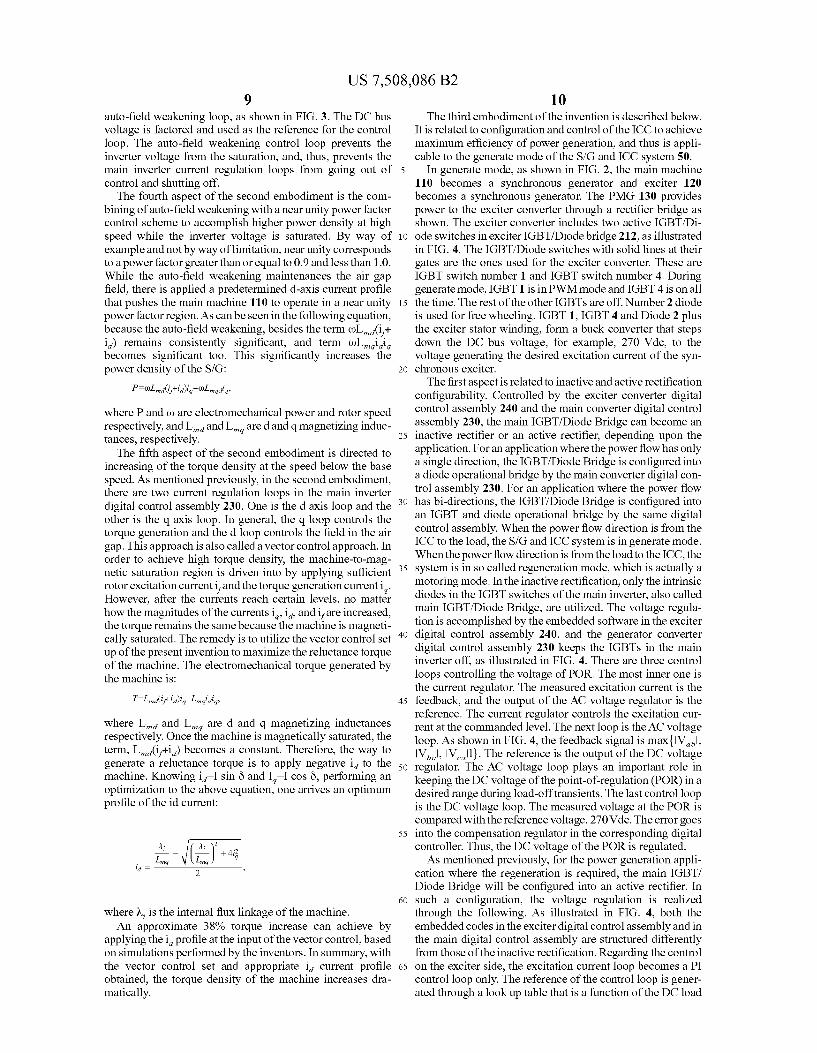
Unfortunately, the frequency of the above angle has tWo times frequency of the fundamental frequency, and thus it cannot be directly used to the Park and Inverse-Park transformations. To convert the above angle to the rotor position angle, it is detected Whether 6' is under a north pole to south pole region or under a south pole to north pole region. If the 6' is under the north pole to south pole region, the angle is
and if the 6' is under the south pole to north pole region, the angle is
This angle, as shoWn in FIG. 7, is then utiliZed in the Park and Inverse-Park transformations in the d and q current regulation loops. As shoWn in FIG. 3, a band-stop ?lter (500 HZ ?lter as shoWn in FIG. 3, Whereby other stop band frequencies may be utiliZed While remaining Within the spirit and scope of the invention) is placed betWeen Clarke and Park transformations to eliminate the disturbances of the carrier frequency on the d and q current regulation loops.
This high frequency injection sensorless method Works satisfactorily at Zero or loW speed. HoWever, the method Will not Work as Well With the speed With Which the frequency is close to or higher than the carrier frequency. Accordingly, another sensorless method is utiliZed When the speed goes
20
25
30
35
40
50
55
60
65
8 above a certain threshold rotational speed, such as 80 rpm. This method is the voltage mode sensorless method, as described beloW. The realiZation of the voltage mode sensorless is accom
plished by the folloWing. Although the method has been used in an induction motor and a PM motor, it has not been applied to a salient synchronous machine because the stator self inductances are not constants, and instead, the inductances are functions of the rotor position. The conventional 0t and [3 ?ux linkage equations in the synchronous stationary frame, Which are used to generate the rotor angle by arctangent of the [3 ?ux linkage over the ot axis ?ux linkage, are not practical to be used for a salient Wound ?eld synchronous machine because the inductances change all the time. To overcome this problem, in the second embodiment, a pair of arti?cial ?ux linkages Na and NB as Well as their expressions, are derived:
Where RS and Lq are the main stator resistance and q axis synchronous inductance respectively. Both of the machine parameters are constant. Fortunately, Na and NB align With the 0t and [3 ?ux linkages, respectively, and the angle
is actually the rotor angle that can be used for Park and Inverse-Park transformations once the machine speed is above the threshold rotational speed, such as above 80 rpm. The equations can be implemented in the embedded softWare of the digital control assembly 230. This approach provides for reliable rotor position angle estimation While the machine speed is above a certain rotational speed, e.g., above 80 rpm. According to the second aspect of the second embodiment,
the combination of tWo separate methods, the high frequency inject sensorless method and the voltage mode sensorless method, provides the rotor position information With su?i cient accuracy throughout the entire speed range of the syn chronous machine based starter.
The third aspect of the second embodiment is directed to the voltage saturation problem of the main inverter that is appropriately dealt With. During starting, the voltage applied by the main inverter on the main machine 110 is proportional to the speed and matches the vector summation of the back EMF and the voltage drops on the internal impedances of the main machine 110. The maximum applicable voltage by the inverter is the DC bus voltage. Once the vector summation is equal to the DC bus voltage, the inverter voltage is saturated. Once the saturation occurs, the speed of the main machine 110 cannot go any higher, and the d and q current regulation loops Will be out of control. Often, the inverter Will be over current and shut off. The solution provided in the second embodiment is to use an auto-?eld Weakening approach. The main digital control assembly 230 measures the line-to-line voltages, Val, andVbc that are sent to the exciter digital control assembly 240 . A Clarke transformation is applied to these tWo line-to-line voltages. The vector summation of the tWo out puts of the transformation is used as the feedback of the
US 7,508,086 B2 9
auto-?eld weakening loop, as shown in FIG. 3. The DC bus voltage is factored and used as the reference for the control loop. The auto-?eld weakening control loop prevents the inverter voltage from the saturation, and, thus, prevents the main inverter current regulation loops from going out of control and shutting off.
The fourth aspect of the second embodiment is the com bining of auto-?eld weakening with a near unity power factor control scheme to accomplish higher power density at high speed while the inverter voltage is saturated. By way of example and not by way of limitation, near unity corresponds to a power factor greater than or equal to 0.9 and less than 1 .0. While the auto-?eld weakening maintenances the air gap ?eld, there is applied a predetermined d-axis current pro?le that pushes the main machine 110 to operate in a near unity power factor region. As can be seen in the following equation, because the auto-?eld weakening, besides the term (nLmd(i/+ id) remains consistently signi?cant, and term uuLmqidiq becomes signi?cant too. This signi?cantly increases the power density of the S/G:
where P and u) are electromechanical power and rotor speed respectively, and Lmd and LW are d and q magnetizing induc tances, respectively.
The ?fth aspect of the second embodiment is directed to increasing of the torque density at the speed below the base speed. As mentioned previously, in the second embodiment, there are two current regulation loops in the main inverter digital control assembly 230. One is the d axis loop and the other is the q axis loop. In general, the q loop controls the torque generation and the d loop controls the ?eld in the air gap. This approach is also called a vector control approach. In order to achieve high torque density, the machine-to-mag netic saturation region is driven into by applying su?icient rotor excitation current ifand the torque generation current i q. However, after the currents reach certain levels, no matter how the magnitudes of the currents i q, i d, and ifare increased, the torque remains the same because the machine is magneti cally saturated. The remedy is to utiliZe the vector control set up of the present invention to maximiZe the reluctance torque of the machine. The electromechanical torque generated by the machine is:
where Lmd and LW are d and q magnetiZing inductances respectively. Once the machine is magnetically saturated, the term, Lmd(if+id) becomes a constant. Therefore, the way to generate a reluctance torque is to apply negative id to the machine. Knowing id:I sin 6 and IqII cos 6, performing an optimiZation to the above equation, one arrives an optimum pro?le of the id current:
where K1. is the internal ?ux linkage of the machine. An approximate 38% torque increase can achieve by
applying the i d pro?le at the input of the vector control, based on simulations performed by the inventors. In summary, with the vector control set and appropriate id current pro?le obtained, the torque density of the machine increases dra matically.
20
25
30
35
40
45
50
55
60
65
10 The third embodiment of the invention is described below.
It is related to con?guration and control of the ICC to achieve maximum ef?ciency of power generation, and thus is appli cable to the generate mode of the S/G and ICC system 50.
In generate mode, as shown in FIG. 2, the main machine 110 becomes a synchronous generator and exciter 120 becomes a synchronous generator. The PMG 130 provides power to the exciter converter through a recti?er bridge as shown. The exciter converter includes two active IGBT/Di ode switches in exciter IGBT/ Diode bridge 212, as illustrated in FIG. 4. The IGBT/Diode switches with solid lines at their gates are the ones used for the exciter converter. These are IGBT switch number 1 and IGBT switch number 4. During generate mode, IGBT 1 is in PWM mode and IGBT 4 is on all the time. The rest of the other IGBTs are off. Number 2 diode is used for free wheeling. IGBT 1, IGBT 4 and Diode 2 plus the exciter stator winding, form a buck converter that steps down the DC bus voltage, for example, 270 Vdc, to the voltage generating the desired excitation current of the syn chronous exciter. The ?rst aspect is related to inactive and active recti?cation
con?gurability. Controlled by the exciter converter digital control assembly 240 and the main converter digital control assembly 230, the main IGBT/Diode Bridge can become an inactive recti?er or an active recti?er, depending upon the application. For an application where the power ?ow has only a single direction, the IGBT/ Diode Bridge is con?gured into a diode operational bridge by the main converter digital con trol assembly 230. For an application where the power ?ow has bi-directions, the IGBT/Diode Bridge is con?gured into an IGBT and diode operational bridge by the same digital control assembly. When the power flow direction is from the ICC to the load, the S/G and ICC system is in generate mode. When the power ?ow direction is from the load to the ICC, the system is in so called regeneration mode, which is actually a motoring mode. In the inactive recti?cation, only the intrinsic diodes in the IGBT switches of the main inverter, also called main IGBT/Diode Bridge, are utiliZed. The voltage regula tion is accomplished by the embedded software in the exciter digital control assembly 240, and the generator converter digital control assembly 230 keeps the IGBTs in the main inverter off, as illustrated in FIG. 4. There are three control loops controlling the voltage of POR. The most inner one is the current regulator. The measured excitation current is the feedback, and the output of the AC voltage regulator is the reference. The current regulator controls the excitation cur rent at the commanded level. The next loop is the AC voltage loop. As shown in FIG. 4, the feedback signal is max{|Vab|, lVbcl, lVcall}. The reference is the output of the DC voltage regulator. The AC voltage loop plays an important role in keeping the DC voltage of the point-of-regulation (POR) in a desired range during load-off transients. The last control loop is the DC voltage loop. The measured voltage at the POR is compared with the reference voltage, 270 Vdc. The error goes into the compensation regulator in the corresponding digital controller. Thus, the DC voltage of the POR is regulated. As mentioned previously, for the power generation appli
cation where the regeneration is required, the main IGBT/ Diode Bridge will be con?gured into an active recti?er. In such a con?guration, the voltage regulation is realiZed through the following. As illustrated in FIG. 4, both the embedded codes in the exciter digital control assembly and in the main digital control assembly are structured differently from those of the inactive recti?cation. Regarding the control on the exciter side, the excitation current loop becomes a PI control loop only. The reference of the control loop is gener ated through a look up table that is a function of the DC load
US 7,508,086 B2 11
current. The table is generated in such a Way the current in the main stator approach to its minimum possible value. The control on the main side outer control loop is the DC voltage loop. The reference is 270 VDC; the feedback signal is the POR voltage. As shoWn in FIG. 4, the control loop is a PI controller With a feedforWard of the DC output poWer added to the output of the PI controller. The DC output poWer is equal to the product of the DC output current and the POR voltage. The sum of the feedforWard signal and the output of the PI controller is a poWer command that is utiliZed as the reference for the inner control loop, Which is also a PI con troller. The feedback signal is the poWer computed by using the voltages and currents of the generator as shoWn in FIG. 4. The output of the inner control loop is the voltage angle 6v Which is de?ned in FIG. 8 and is utiliZed to generate the SVPWM vectors V d* and V (1*. The tWo vectors are the input of the Park inverse transformation. The output of the trans formation is the input of the SVPWM as shoWn in FIG. 4.
The second aspect of the third embodiment is related to control of the IGBT converter that combines auto-?eld modi ?cation and over-modulation to achieve optimum e?iciency of the IGBT generate mode operation. As presented in FIG. 4, V d* andV (1* are calculated through
the folloWing equations:
To optimiZe the ef?ciency, ?rst, Vmag is chosen to be 1 pu, thus forcing the converter into the full over-modulation region and completely dropping the IGBT sWitching caused by SVPWM. This minimiZes the IGBT sWitching losses. The IGBT acts like phase shifting sWitching. Because Vmag is constant, the poWer loop regulates the poWer by adjusting the angle 6v. When the load is Zero, 6v approaches to Zero, and When the load increases, 6v increases as shoWn in FIG. 8.
The second factor of achieving the optimiZed ef?ciency is to optimiZe the exciter ?eld current so i d current is minimiZed. Thus, the conduction losses of the IGBTs and copper losses of the generator are minimized. It is found that the exciter ?eld current is directly related to the DC load current. The higher DC load current is, the higher exciter ?eld current is required. For the purpose of achieving of minimum exciter ?eld cur rent, a look up table is generated through measurement. The input of the look up table is the DC load current, and the output of look up table is the command of the exciter ?eld current of the exciter stator. The table is generated in such a Way that for each a DC load current point, an optimal exciter ?eld current is found When i d current is at its minimum. Such a control method not only achieves the optimal ef?ciency of the S/G and ICC system, but also provides an effective approach such that the operational point can easily sWing from generate mode to regenerate mode, i.e., motoring mode. Thus, sending back the excessive energy on the DC bus to the generator in a fastest manner is accomplished. The third aspect of the third embodiment is directed to providing an IGBT commutation approach during generate mode. The IGBTs’ commutation is based on a sensorless voltage mode, Which is a similar sensorless approach used in start mode. HoWever, because the operating mode changes betWeen diode only mode and IGBT mode, the rotor position angle is determined before going into the IGBT mode. Va and Vl3 are
20
25
30
35
40
45
50
55
60
12 obtained directly from the line-to-line voltage measurement instead of from the SVPWM commands. The fourth aspect of the third embodiment is related to
accomplishing regeneration in absorbing excessive energy on the DC bus into the machine While regulating the bus voltage simultaneously. During generate mode, there can be exces sive energy created by the load. Such excessive energy raises the DC bus voltage. This energy can be absorbed by the machine through the regeneration approach provided by the over-modulation SVPWM of this invention. During this situ ation, as illustrated in FIG. 8, the main inverter digital control reverses the direction of the voltage angle 6v, and forces the main IGBT/Diode Bridge into motoring mode. Thus, the direction of the poWer How Will be reversed. The poWer Will ?oW from the load into the machine. The over-modulation keeps the IGBTs from sWitching, thus, minimiZes the sWitch ing losses. This aspect of the invention provides a fast Way to sWing the main IGBT/Diode Bridge from generate mode to regenerate mode, and vice versa.
Thus, embodiments of the present invention have been described in detail. Other embodiments of the invention Will be apparent to those skilled in the art from consideration of the speci?cation and practice of the invention disclosed herein. It is intended that the speci?cation and examples be considered as exemplary only. The invention claimed is: 1. An aircraft starting and generating system, comprising:
a starter/ generator that includes a main machine, an exciter, and a permanent magnet generator; and
an inverter/converter/controller (ICC) that is connected to the starter/generator and that generates AC poWer to drive the starter/ generator in a start mode for starting a prime mover of the aircraft, and that converts AC poWer, obtained from the starter/ generator after the prime mover have been started, to DC poWer in a generate mode of the starter/ generator, the ICC including a con tactor,
Wherein the exciter includes a stator and a rotor, and Wherein the exciter stator includes a Winding that is con?gured to Work conj unctionally With the contactor to function as an AC Winding during the start mode, and that is con?gured to Work conjunctionally With the con tactor as a DC Winding during the generate mode.
2. The aircraft starting and generating system according to claim 1, Wherein the inverter/ converter/ controller comprises:
a main insulated-gate bipolar transistor (IGBT) bridge that is connected to a main stator of the main machine; and
an exciter insulated-gate bipolar transistor (IGBT) Bridge that is connected to an exciter stator of the exciter.
3. The aircraft starting and generating system according to claim 1, Wherein the starter/ generator further comprises:
a full Wave or half-Wave recti?er, Wherein the exciter includes an exciter rotor and an exciter
stator, and Wherein the full Wave or half Wave recti?er is provided on
a shaft of the exciter rotor, and rotates With rotation of the exciter shaft.
4. The aircraft starting and generating system according to claim 2, Wherein the contactor provides connection of the exciter insulated-gate bipolar transistor (IGBT) bridge With the exciter stator during the start mode.


![The starter generator!_mark_ii[1]](https://img.dokumen.tips/doc/110x75/546fb074af79591e2e8b4584/the-starter-generatormarkii1.jpg)