Embed Size (px)
Citation preview

INSTALLATION GUIDEINSTALLATION GUIDE
HomeNetworkingSolutions


3INSTALLATION GUIDEINSTALLATION GUIDEINSTALLATION GUIDE
CLIPSAL STARSERVE® INSTALLATION GUIDE - CONTENTS
Section 1 - What is Clipsal StarServe®?What is Clipsal StarServe®?.................................................................................. 4
Video Distribution .................................................................................................. 4
Telephone and Data Distribution ........................................................................... 5
Section 2 - Introduction to MATV BasicsMATV Introduction ................................................................................................ 6
Signal Strength ...................................................................................................... 7
Signal Quality ......................................................................................................... 8
Signal Losses - Cable ............................................................................................ 9
Signal Losses - Splitters ..................................................................................... 10
Clipsal Antennas - High Performance Models ....................................................11
Section 3 - Clipsal StarServe® Product Introduction3105ABEN Slimline Enclosure............................................................................. 12
8000LEN Lite Sized Enclosure ............................................................................ 13
8000MEN Mid Sized Enclosure ........................................................................... 14
3105PENF / 3105PENS Professional Enclosures ............................................... 15
Video Distribution Units ................................................................................. 16-17
3105VDU38IRT Distribution Unit ........................................................................ 18
3105VDU24T Distribution Unit ........................................................................... 19
8073/8VHPIR Video Hub ..................................................................................... 20
8072/6VHP Video Hub ........................................................................................ 21
Clipsal StarServe® VDU Power Options ............................................................. 22
Clipsal Digital Ready Antennas ........................................................................... 25
Modulators ........................................................................................................... 26
Emitter Leads & Infrared Targets ........................................................................ 27
Patch Panels - Data and Telephone ..................................................................... 28
Switches - Data Patch Panels ............................................................................. 29
8001/4EX Output Expander ................................................................................. 30
8000INJ IR Injector ............................................................................................. 30
8000DCB DC Block .......................................................................................... 31
8000AVB RCA to Cat-5 Cable Adaptor ................................................................ 31
Section 4 - Minimum TV Cabling RequirementsTV Cabling Requirements .................................................................................... 32
F-Type Connectors ............................................................................................... 32
MATV Tools Required .......................................................................................... 32
TV Mechs ............................................................................................................. 33
TV Fly Leads......................................................................................................... 33
Digital Terrestrial Meter ...................................................................................... 33
Conventional TV Cabling ..................................................................................... 34
Clipsal StarServe® TV Cabling ............................................................................ 35
3105VDU38IRT TV Wiring Diagram ................................................................... 36
3105VDU24T TV Wiring Diagram ....................................................................... 37
8073/8VHPIR TV Wiring Diagram ...................................................................... 38
8072/6VHP TV Wiring Diagram .......................................................................... 39
Section 5 - Video Distribution - How To ConnectAntenna Input ...................................................................................................... 40
Antenna Input - Using an Amplifi er with the VDU .............................................. 41
Antenna Outputs .................................................................................................. 42
Modulator Input B - Distribution of Devices ....................................................... 43
Setup of the Modulator ........................................................................................ 44
Modulator AV Connections.................................................................................. 45
Modulator AV Connections - Y-Lead Connections ............................................. 46
IR Emitter Leads .................................................................................................. 47
IR Target ............................................................................................................... 48
IR Control of Devices ........................................................................................... 49
Modulator Input A - Single Surveillance Camera ............................................... 50
Modulator Input A - Multiple Surveillance Cameras .......................................... 51
Surveillance Camera Connection Using an AV Balun ......................................... 52
Section 6 - Phone/Data Minimum Cabling RequirementsTelephone/Data Cabling ...................................................................................... 53
Patch Panels ........................................................................................................ 53
Ethernet Switches ................................................................................................ 53
Patch Leads ......................................................................................................... 53
Required Data Tools ............................................................................................ 53
Recommended Cabling ....................................................................................... 54
Section 7 - Telephone/Internet - How To ConnectTelephone Connection ......................................................................................... 55
Jumpering Telephone Outlets ............................................................................. 56
Mode 3 Security System Connection ................................................................. 57
ADSL Connection ................................................................................................. 58
ADSL Connection with Jumpering Leads ........................................................... 59
ADSL Switch Modem Router Connection ........................................................... 60
Section 8 - Data Cabling - How To ConnectPatch Panel Setup - Data Cabling ....................................................................... 61
Patch Panel Connection for Structured Cabling System ................................... 62
Telephone Distribution Using a Telephone Patch Panel ..................................... 63
Section 9 - Subscription TV Cabling Requirements/OverviewFOXTEL IQ Cabling Requirements - Single Outlet Domestic ............................. 64
AUSTAR Cabling Requirements - Single Outlet Domestic ................................. 65
Multiple Subscription TV Decoder Cabling Requirements - Domestic ............. 66
Apartment Cabling Requirements - Commercial Installations .......................... 67
Section 10 - Cabling ConsiderationsKey Area 1 - The Lounge Room ........................................................................... 68
Key Area 2 - The Master Bedroom ...................................................................... 69
Key Area 3 - Other Bedrooms .............................................................................. 69
Key Area 4 - Study/Other Bedrooms................................................................... 69
Key Area 5 - The Kitchen ..................................................................................... 70
Smart Wired Wall Plate ....................................................................................... 70
Other Areas .......................................................................................................... 70
Section 11 - Troubleshooting GuidesInfrared Troubleshooting Guide ..................................................................... 71-72
TV Reception Troubleshooting Guide - Free to Air Picture ........................... 73-74
TV Reception Troubleshooting Guide - Modulated Channels .............................74
Section 12 - Clipsal StarServe® FAQsClipsal Starserve Frequently Asked Questions .............................................75-76
Notes PagesNotes ............................................................................................................... 77-79

SECTION 1 What is Clipsal StarServe®?
4 INSTALLATION GUIDEINSTALLATION GUIDEINSTALLATION GUIDE
What is Clipsal StarServe®?
Clipsal StarServe® is three distribution systems in one for the home:
You can take advantage of just one or utilise all three areas - the choice is yours.
Video Distribution
Apart from distributing analogue or digital free to air TV, Clipsal StarServe® also enables the user to distribute other
devices such as DVD players, video recorders, subscription TV decoders and surveillance cameras to be viewed on
any TV connected to the Clipsal StarServe®.
Now every TV in your home can access free to air channels, subscription TV decoders, DVD players, video recorders,
surveillance cameras, etc.
Clipsal StarServe® unlocks your home entertainment centre. Now everyone can watch what they want, when they
want to watch it.
Some models will allow the IR control of these other devices from rooms other than the main entertainment area.
Digital and AnalogueVideo Distribution
Data Networking
AND/OR AND/OR
Telephone/InternetDistribution
Only TWO extra coax cables are required in addition to the standard TV cabling.

SECTION 1 What is Clipsal StarServe®?
5INSTALLATION GUIDEINSTALLATION GUIDEINSTALLATION GUIDE
Telephone and Data Distribution
In today’s homes the need to have telephone access and internet access is essential.
Clipsal StarServe® facilitates the distribution of telephone and internet cabling in a simple and easy to understand
manner. Clipsal StarServe® can also facilitate a high-speed data network so that you can network computers, printers
and AV equipment together.
Hard wired cabling is the best possible solution for any installation but failure to prepare for cabling may be very
costly in the future. The cost of trying to install cabling after a new home has been built is approximately three to four
times the initial cost. If you have a two storey home then it may be impossible to get cables down walls unless you
make holes and damage walls or ceilings.
Even if you are going to have a wireless network within your home, Clipsal StarServe® can accommodate this
requirement and connect your wireless network to the Internet.
3105PENFClipsal StarServe®
Enclosure

SECTION 2 Introduction to MATV Basics
6 INSTALLATION GUIDEINSTALLATION GUIDEINSTALLATION GUIDE
MATV Introduction
What does MATV stand for?
Master Antenna TeleVision:
The master antenna is used for supplying one TV outlet, or multiple TV outlets with TV signals. The most basic MATV
system is an antenna connected to a TV outlet, along with a fl y lead to connect the system to the TV.
The antenna is designed to receive TV signals. The cable is designed to carry the TV signals to the outlet. The outlet
is the interface for a fl y lead to connect to the TV. The fl y lead connects the wall plate to the TV.
Where multiple outlets are required a splitter or series of splitters are used to distribute the signal to as many
outlets as required.
IMPORTANT NOTE:All Clipsal MATV products including Clipsal StarServe® are capable of
distributing DIGITAL AND ANALOGUE free to air TV signals.
Analogue TV VHF 0 - 12 & UHF 28 - 69Digital TV VHF 6 - 12 & UHF 28 - 69
Wall Outlet
Fly Lead
The antenna is designed to receive the TV signal.The cabling system is designed to carry the TV signal to the TV without any interference.
Wall Outlets Fly Leads
Antenna
Splitter

SECTION 2 Introduction to MATV Basics
7INSTALLATION GUIDEINSTALLATION GUIDEINSTALLATION GUIDE
Signal Strength
The principals of signal strength for MATV systems are not unlike that of the electrical principals for voltage at power points.
The units of measurement are as follows:
• electrical unit of measurement is the Volt (V)
• MATV unit of measurement is the decibel Micro Volt (dBuV), commonly referred to as “dB”.
The ideal voltage for a power outlet is 240 Volts, with a tolerance of 5%. This means that you can have as low as 228
Volts or as high as 252 Volts to comply with the Australian Standards.
The voltage is measured using a multimeter. You set the multimeter to the voltage setting and test for voltage. The
ideal signal level for a combined analogue / digital MATV system is similar.
The ideal MATV signal strength at the outlet is 69dBuV with a tolerance of 5%. For excellent quality pictures, you
require signal strength between 65-72dBuV. The MATV signal strength is measured using a fi eld strength meter. You
set the fi eld strength meter to the channel you wish to test and it will show you a reading of the signal at the outlet.
Ideal Signal Levels
MATV Outlet - 69dBuV Standard Outlet - 240V
Test with fi eld strength meter Test with multi meter
A fi eld strength meter is ESSENTIAL.
LOW SIGNAL TOO LOW TOO HIGH
HIGH SIGNAL
69dBuV62dBuV 65dBuV 228V 252V72dBuV 75dBuV
ACCEPTABLESIGNAL

SECTION 2 Introduction to MATV Basics
8 INSTALLATION GUIDEINSTALLATION GUIDEINSTALLATION GUIDE
Signal Quality
There are two parts to a perfect TV picture, signal strength and signal quality. You can have excellent signal strength
but if your signal quality is poor then this will result in poor quality pictures.
Many of the problems faced with signal quality have been overcome with the introduction of digital TV. For example
with digital TV you will not get “ghosting”. Clear line of sight is obviously the best possible scenario for high quality
TV reception but often cannot be achieved.
We need to avoid the following when installing antennas:
• DO NOT install antennas in the ceiling space
• DO NOT install antennas with trees in the way of line of sight
• DO NOT install antennas within one metre of the roof.
Before you install an antenna:
• DO a site survey; this is a walk on the roof with
an antenna and digital fi eld strength metre. This
will give you an indication of the best possible
location to install the antenna on the roof
• DO check each TV station on the site survey. This
confi rms that it is the best possible location for all
TV stations reception.
Bit error rate
BER – Bit error rate measures the number of
errors on the incoming signal. Too many errors
will result in pixilation, boxing or freezing of the
picture. There is a four star rating associated with
digital signal reception:
FAIL FAIL PASS PASSVERY POOR QUALITY POOR QUALITY GOOD QUALITY EXCELLENT QUALITY
No picture
Pixelated picture
It is the installer’s responsibility to follow the appropriate Occupational Health and Safety (OH&S) work practices.

SECTION 2 Introduction to MATV Basics
9INSTALLATION GUIDEINSTALLATION GUIDEINSTALLATION GUIDE
Signal Losses - Cable
Losses are a part of any MATV system. You may start out with an acceptable signal level at the antenna but due to
losses in the cable or splitter, the signal may not be acceptable when at the outlet.
Losses are calculated separately for VHF and UHF frequencies. The golden rule; is the higher the frequency the higher
the loss.
VHF = Very High Frequency 45 - 470 MHz Channels 0 - 12
UHF = Ultra High Frequency 471 - 860 MHz Channels 21 - 69
We need to calculate losses for both VHF and UHF in every TV design to ensure that we have a balanced system.
Clipsal RG6 cable losses are linear. This means that you can multiply the losses for one metre by the length of the
cable run to get the losses over that distance.
2B6QXX Cable Losses Frequency 1.0m 5.0m 10.0m 20.0m 30.0m
VHF (0-12) 0.053dB 0.265dB 0.53dB 1.06dB 1.59dB
UHF (21-69) 0.21dB 1.05dB 2.1dB 4.2dB 6.3dB
A balanced system is a MATV system that has an acceptable signal level (65-72dBuV) at every outlet within the
system, regardless of the length of cable to the outlet.
In domestic settings this is not usually an issue if the distribution of the signal is from a central location. This is more
of an issue when distributing TV signals to multi storey apartments and hotels with long cable runs.
In a domestic situation the shortest cable run can be one metre and the longest cable run can be 45 metres without
having to use some form of equalisation to balance the system.
45 Metres 1 Metre

SECTION 2 Introduction to MATV Basics
10 INSTALLATION GUIDEINSTALLATION GUIDEINSTALLATION GUIDE
Signal Losses - Splitters
Losses over splitters are just as important to calculate as the losses over cable. The value of the loss will be different
for VHF and UHF (the golden rule is the higher the number of splits, the higher the losses).
The Clipsal StarServe® VDU is a NO-LOSS SPLITTER.
The losses over each output port of the splitter are the same.
If you changed a two way splitter for a four way splitter you may have poor picture quality due to the fact that you
have added losses into the system and reduced the signal strength to each outlet by 4dB on VHF and 3.4dB on UHF.
An eight way splitter would also require an amplifi er.
Frequency 2 Way 3 Way 4 Way 6 Way 8 Way
46-470MHz VHF < 3.5dB < 6.1dB < 7.5dB < 10.2dB < 11.2dB
471-860MHz UHF < 4.4dB < 6.3dB < 7.8dB < 10.7dB < 11.8dB
SIGNAL IN70dBuV
SIGNALOUT
VHF: 57.8dBUHF: 57.2dB
SIGNALNO LOSS
Option of 5dB GAINor 15dB ATTENUATION
SIGNAL OUT72dBuV
SIGNAL IN70dBuV
Antenna input

SECTION 2 Introduction to MATV Basics
11INSTALLATION GUIDEINSTALLATION GUIDEINSTALLATION GUIDE
Clipsal Antennas - High Performance Models
13 Element VHF 1-12 UHF 28-502ANCOM3For use in PRIME signal reception areas.
This antenna will suit areas such as Adelaide, Melbourne,
Sydney, Brisbane, Perth, Hobart and Launceston.
17 Element VHF 2-12 UHF 28-402ANCOM4For use in FRINGE signal reception areas.
This antenna will suit areas such as Adelaide, Melbourne,
Sydney, Brisbane, Perth, Hobart and Launceston.
28 Element VHF 2-12 UHF 28-402ANCOM6For use in OUTER FRINGE signal reception areas.
This antenna will suit areas such as Adelaide, Melbourne,
Sydney, Brisbane, Perth, Hobart and Launceston.
14 Element VHF 6-12 UHF 28-502ANCOMD14For use in PRIME/FRINGE signal reception areas.
This antenna will suit both digital and analogue signals
from VHF 6-12 and UHF 28-50.
14 Element - Wide Band VHF 6-12 UHF 28-692ANCOMD14WBFor use in PRIME/FRINGE signal reception areas.
This antenna will suit both digital and analogue signals
from VHF 6-12 and UHF 28-69.
24 Element VHF 6-12 UHF 28-502ANCOMD24For use in FRINGE signal reception areas.
This antenna will suit both digital and analogue signals
from VHF 6-12 and UHF 28-50.

SECTION 3 Clipsal StarServe® Product Introduction
12 INSTALLATION GUIDEINSTALLATION GUIDEINSTALLATION GUIDE
Slimline Enclosure3105ABEN
Features
• Designed to be recessed into 63mm stud walls.
• Installed at second fi x stage.
• 1-11 RG6 quad shield coax cables for TV distribution.
• 1-8 Category 5e or Category 6 data cables for structured cabling network.
• 1-4 Incoming telephone lines.
• 1 x 4 port ADSL switch / modem router (Netgear product number DG834).
• Cut-out template provided.
Specifi cations
Dimensions: 383mm high x 269mm wide x 88mm deep (74mm deep in wall)
Cut out size: 356mm high x 213mm wide x 74mm deep
The size of the enclosure is determined by the number of cables and active equipment required inside the enclosure. Choose an appropriate enclosure to accommodate the cabling required for the installation.

SECTION 3 Clipsal StarServe® Product Introduction
13INSTALLATION GUIDEINSTALLATION GUIDEINSTALLATION GUIDE
Lite Sized Enclosure8000LEN
Features
• Small enclosure to suit TV and / or telephone distribution.
• 1-11 RG6 quad shield coax cables for TV distribution.
• 1-8 Category 5e or Category 6 data cables for telephone distribution.
• 1-4 Incoming telephone lines.
Specifi cations
Dimensions: 330mm high x 210mm wide x 130mm deep
8000LENFK - Flushing kit available
The size of the enclosure is determined by the number of cables and active equipment required inside the enclosure. Choose an appropriate enclosure to accommodate the cabling required for the installation.
8000LEN Enclosure 8000LENFK Enclosure Flushing Kit

SECTION 3 Clipsal StarServe® Product Introduction
14 INSTALLATION GUIDEINSTALLATION GUIDEINSTALLATION GUIDE
Mid Sized Enclosure8000MEN
Features
• Two vertical rails for increased wiring room and more cables.
• Surface mount.
• Flushing kit available for recess mount.
• 1-11 RG6 quad shield coax cables for TV distribution.
• 1-16 Category 5e or Category 6 data cables for structured cabling network.
• 1-4 Incoming telephone lines.
• 1 x 3105ADJB Audio distribution junction box for more than four zones of audio distribution.
Specifi cations
Enclosure: 450mm high x 415mm wide x 145mm deep
8000MENFK - Flushing Kit available
The size of the enclosure is determined by the number of cables and active equipment required inside the enclosure. Choose an appropriate enclosure to accommodate the cabling required for the installation.
8000MEN Enclosure 8000MENFK Enclosure Flushing Kit

SECTION 3 Clipsal StarServe® Product Introduction
15INSTALLATION GUIDEINSTALLATION GUIDEINSTALLATION GUIDE
Professional Flush Mount Enclosure3105PENF
Features
• Choice of fi rst fi x or second fi x mounting.
• Suits different thickness’ of plaster board: 10mm, 13mm and 16mm.
• Dual power outlet inside enclosure.
• Family look – power, C-Bus and Clipsal StarServe® in the same style of enclosure.
• 1-21 RG6 quad shield coax cables for TV distribution.
• 1-48 Category 5e or Category 6 data cables for structured cabling network.
• 1-8 Incoming telephone lines.
• 1 x 3105ADJB Audio distribution junction box for more than four zones of audio distribution.
• Uses keystone data jacks available in CAT5e and Cat6 (RJ88SMAS, RJ88SMA6).
Specifi cations
3105PENF
Enclosure: 880mm high x 466mm wide x 119mm deep
Cut out size: 882mm high x 468mm wide x 69mm deep
Recessed frame: 954mm high x 525mm wide
3105PENS
Dimensions: 880mm high x 466mm wide x 114mm deep
Professional Surface Mount Enclosure3105PENS
The size of the enclosure is determined by the number of cables and active equipment required inside the enclosure. Choose an appropriate enclosure to accommodate the cabling required for the installation.
3105PENF Enclosure 3105PENS Enclosure

SECTION 3 Clipsal StarServe® Product Introduction
16 INSTALLATION GUIDEINSTALLATION GUIDEINSTALLATION GUIDE
Video Distribution Units
3105VDU38IRT 3105VDU24T 8072/6VHP 8073/8VHPIR
MATV AND TELEPHONES MATV ONLY
Distribution
The VDU distributes digital and analogue free to air TV signals from the antenna input to all TV outputs on the VDU. This
works as a splitter but one of the special features is that the Clipsal VDU is a powered splitter which has no losses from
the input to the outputs.
NOTE: The Clipsal StarServe® VDU is classed as one TV point when choosing an antenna.
Variable Gain Control
The Clipsal StarServe® VDU has a variable gain control to make it easy to adjust for the ideal
signal strength and best possible picture. The variable gain control can amplify the incoming
signal by 5dBuV or decrease the signal strength by 15dBuV. This feature of the Clipsal
StarServe® VDU makes installation easy.
Selectable FM Trap
The selectable FM trap is a feature that is built into the Clipsal StarServe® VDU. FM frequencies
can cause interference with other TV frequencies and need to be removed from the distribution
system. This can be done with the push of a button on the Clipsal StarServe® VDU.
Combination VDU
A combination VDU has been designed to suit the recessed slimline enclosures required in
today’s markets. These VDUs combine the features of the TV cabling and the connection of
the telephone, security system and ADSL services to create a neat, compact solution. These
are entry level solutions and are ‘set and forget’ style products, when using these products there
is no requirement for patching to achieve a basic setup.
The telephone card can accept one to four incoming telephone lines and distribute up to four locations for each line.
The telephone lines can be expanded by jumpering from one to another.
In other words, one incoming line can be expanded to 16 outlets and two incoming lines can be expanded to up to
eight outputs per line.
There is a Mode 3 socket for the connection of a security system to VDU models 3105VDU38IRT and 3105VDU24T.

SECTION 3 Clipsal StarServe® Product Introduction
17INSTALLATION GUIDEINSTALLATION GUIDEINSTALLATION GUIDE
Modulated Inputs
The modulated inputs on the Clipsal StarServe® VDU are designed for the connection of a modulator to the VDU. This
enables the distribution of other devices such as a DVD player, VCR, subscription TV decoder or surveillance camera
to all TV outputs on the VDU.
There are two types of VDU modulated inputs:
3105VDU24T & 8072/6VHP
The modulated inputs on the 3105VDU24T and 8072/6VHP are designed for the connection
of a modulator to distribute devices such as subscription TV decoders, DVD players, VCRs,
etc from one central location to all outputs on the VDU.
The VDU can be powered remotely from this modulated input over the coax cable.
The 3105VDU24T and 8072/6VHP have no IR (Infrared) control of these devices.
3105VDU38IRT & 8073/8VHPIR
There are two modulated inputs on these models that allow for the distribution of devices to
all TV outputs.
Modulator Input A is designed for the connection of a modulator to distribute devices that do not
require IR control such as surveillance cameras. This modulator input cannot be used to power the VDU.
Modulator Input B is designed for the distribution of devices such as subscription TV decoders, DVD players, VCRs,
etc from one central location to all outputs on the VDU with the potential of IR remote control of these devices from
other rooms. This modulated input can be used to remotely power the VDU.
These models have an IR engine built into the VDU to enable the IR control of devices from remote locations with the
addition of an IR compatible modulator, IR emitter leads and IR targets.
Power Output
The power output has been designed to power an external device such as a switch/modem
router that uses the same 12V d.c. power plug at the VDU.
This feature was built to accommodate a fully working system that does not require 240V
power inside the enclosure which houses the active equipment.

SECTION 3 Clipsal StarServe® Product Introduction
18 INSTALLATION GUIDEINSTALLATION GUIDEINSTALLATION GUIDE
Infrared Video and Telephone Distribution Unit3105VDU38IRT
Suitable for ALL Clipsal StarServe® Enclosures
Antenna input
Enables the user to remotely control subscription TV, DVDs etc from another
room in conjunction with theClipsal IR products
Has a security connection for your security system alarm dialler
12Vd.c. power input
Distributes digital ready TV toeight locations of your choice
Modulator input ‘A’ for the distribution of devices such as surveillance cameras via
a modulator to all TV outputs of the VDU(Modulator sold separately)
INPUT A has no Infrared control
Modulator input ‘B’ for the distribution of subscription TV, DVD and video via a modulator
(Modulator sold separately)
Distributes four telephone, dial- up internet or fax lines up to four locations
for each line
Telephone distribution only, NOT DATA
Variable gain control for adjusting output signal strength to optimum levels
Has a selectable FM trapfor fi ltering out
unwanted signals
12Vd.c. power output for switch modem
routers
IR expansion port:Allows infrared
connectivity fromone VDU to another

SECTION 3 Clipsal StarServe® Product Introduction
19INSTALLATION GUIDEINSTALLATION GUIDEINSTALLATION GUIDE
Video and Telephone Distribution Unit3105VDU24T
PLEASE NOTE: this model DOES NOT support the remote control of devices in other rooms
Suitable for ALL Clipsal StarServe® Enclosures
Antenna input
Has a security connection for your security system alarm dialler
Distributes digital ready TV tofour locations of your choice
Variable gain control for adjusting output signal strength to optimum levels
Has a selectable FM trapfor fi ltering out
unwanted signals
Distributes four telephone, dial- up internet or fax lines up to four locations
for each line
Telephone distribution only, NOT DATA
Modulator input for the distribution of other services such as subscription TV,
DVD, video, surveillance cameras etc. via a modulator to all TV outputs of the VDU
(Modulator sold separately)
12Vd.c. power output for switch modem
routers
12Vd.c. power input

SECTION 3 Clipsal StarServe® Product Introduction
20 INSTALLATION GUIDEINSTALLATION GUIDEINSTALLATION GUIDE
Video Hub8073/8VHPIR
Suitable for 3105PENF, 3105PENS, 8000MEN and 8000LEN Enclosures
Antenna input
12V d.c. power input
Distributes digital ready TV toeight locations of your choice
Modulator input ‘A’ for the distribution of devices such as surveillance cameras via
a modulator to all TV outputs of the VDU(Modulator sold separately)
INPUT A has no infrared control
Modulator input ‘B’ for the distribution of subscription TV, DVD, video via a modulator
(Modulator sold separately)
Variable gain control for adjusting output signal strength to optimum levels
Has a selectable FM trapfor fi ltering out
unwanted signals

SECTION 3 Clipsal StarServe® Product Introduction
21INSTALLATION GUIDEINSTALLATION GUIDEINSTALLATION GUIDE
Video Hub8072/6VHP
Suitable for 3105PENF, 3105PENS, 8000MEN and 8000LEN Enclosures
Antenna input
Modulator input for the distribution of other services such as subscription TV,
DVD, video, surveillance cameras etc. via a modulator to all TV outputs of the VDU
(Modulator sold separately)
12 Vd.c. power input
Distributes digital ready TV tosix locations of your choice
Variable gain control for adjusting output signal strength to optimum levels

SECTION 3 Clipsal StarServe® Product Introduction
22 INSTALLATION GUIDEINSTALLATION GUIDEINSTALLATION GUIDE
Clipsal StarServe® VDU Power Options
Remote Powering of the VDU - Modulator
The modulator can be used to power the VDU instead of the power injector. You connect the modulator to the “MOD
INPUT B” of the VDU.
You must make sure that the VDU is disconnected from any other means of power before you remotely power the VDU.
Simply slide the remote power switch from OFF to ON. This will power the VDU from the modulator.
B 1 2Wallplate locatedin your MAIN
ENTERTAINMENT AREA
RG6 QuadshieldCables
DO NOT connect a power supply to the VDUwhen it is being powered via the modulator.
The IR system will only work when the remote power switch is in the ON position.
SECTION 3 Clipsal StarServe® Product Introduction
23INSTALLATION GUIDEINSTALLATION GUIDEINSTALLATION GUIDE
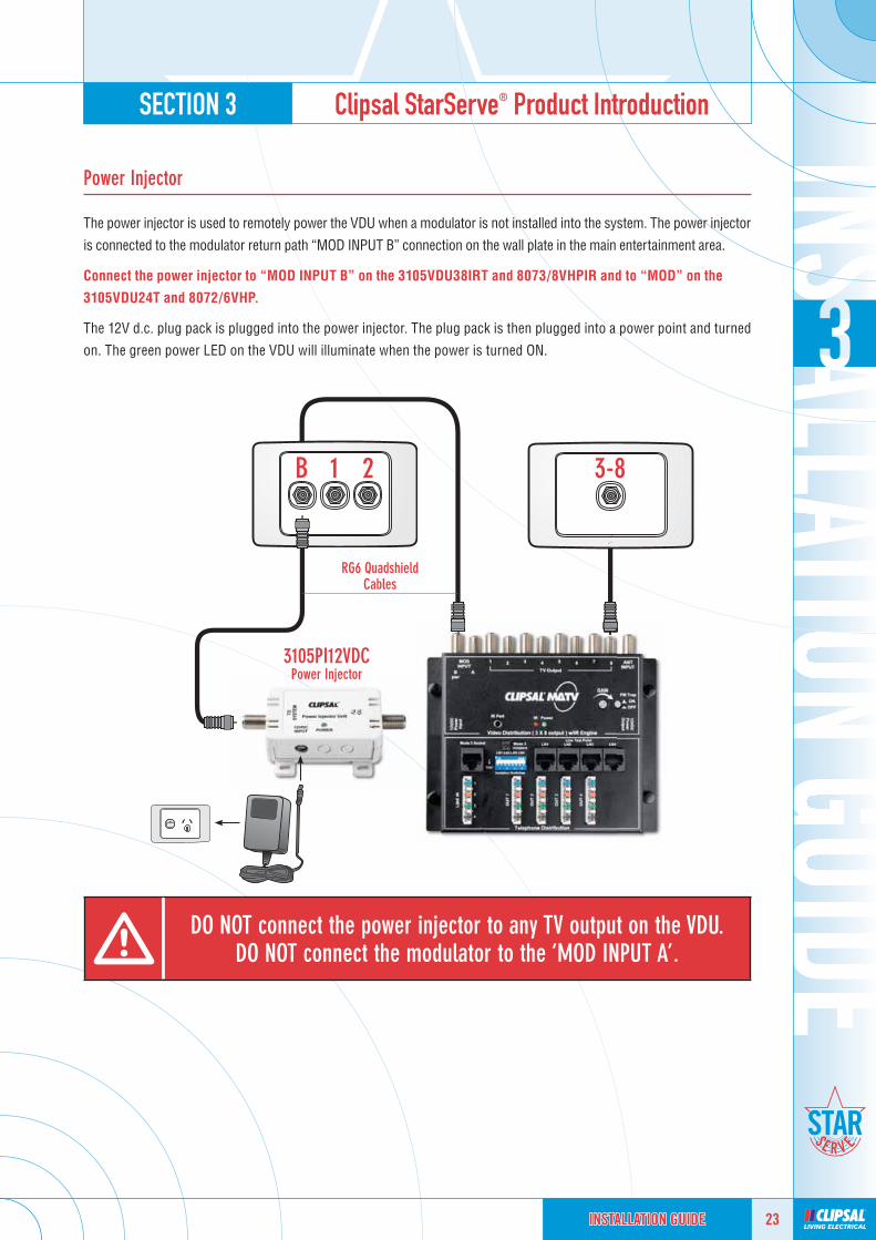
Power Injector
The power injector is used to remotely power the VDU when a modulator is not installed into the system. The power injector
is connected to the modulator return path “MOD INPUT B” connection on the wall plate in the main entertainment area.
Connect the power injector to “MOD INPUT B” on the 3105VDU38IRT and 8073/8VHPIR and to “MOD” on the
3105VDU24T and 8072/6VHP.
The 12V d.c. plug pack is plugged into the power injector. The plug pack is then plugged into a power point and turned
on. The green power LED on the VDU will illuminate when the power is turned ON.
3-8B 1 2
RG6 QuadshieldCables
3105PI12VDCPower Injector
DO NOT connect the power injector to any TV output on the VDU.DO NOT connect the modulator to the ‘MOD INPUT A’.
SECTION 3 Clipsal StarServe® Product Introduction
24 INSTALLATION GUIDEINSTALLATION GUIDEINSTALLATION GUIDE
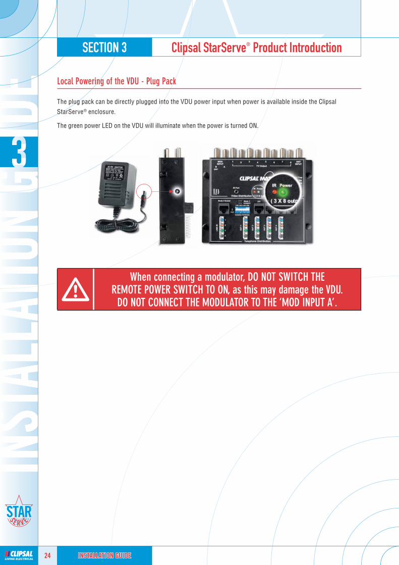
Local Powering of the VDU - Plug Pack
The plug pack can be directly plugged into the VDU power input when power is available inside the Clipsal
StarServe® enclosure.
The green power LED on the VDU will illuminate when the power is turned ON.
When connecting a modulator, DO NOT SWITCH THEREMOTE POWER SWITCH TO ON, as this may damage the VDU.
DO NOT CONNECT THE MODULATOR TO THE ‘MOD INPUT A’.

SECTION 3 Clipsal StarServe® Product Introduction
25INSTALLATION GUIDEINSTALLATION GUIDEINSTALLATION GUIDE
Clipsal Digital Ready TVClipsal Digital Ready TV
To obtain a brochure or forfurther information call 1800 728 728
When it comes to antenna installation, the choice is clear
TV Cabling Solutions CatalogueSolutions Catalogue
Catalogue number: 11954

SECTION 3 Clipsal StarServe® Product Introduction
26 INSTALLATION GUIDEINSTALLATION GUIDEINSTALLATION GUIDE
Modulators
Modulators connect active devices such as your subscription TV decoder and DVD player so that they can be distributed
to all other TV outlets connected to Clipsal StarServe®. The modulator converts composite video signals into analogue
UHF frequencies. Your TV or tuner must be able to receive analogue frequencies for modulated channels.
Single Channel Modulator - 8071VMP (MONO) and 8071VMS (STEREO)
Single channel modulators will distribute one device to any TV connected to Clipsal StarServe®. A single channel
modulator is generally used for the distribution of surveillance cameras at the front door.
2 Channel Modulator - 8072VMPIR (MONO) and 3105M2SIR (STEREO)
Two channel modulators will distribute two devices such as subscription TV and a DVD player. This model is IR enabled to
allow for the remote controlling of devices in other rooms over the coax cable. Up to four devices can be controlled using
dual emitter leads.
4 Channel Modulator - 8074VMPIR (MONO) and 3105M4SIR (STEREO)
Four channel modulators will distribute four devices such as subscription TV, DVD, video and a digital set top box to
all outlets connected to Clipsal StarServe®.
This model is IR enabled to allow for the remote controlling of devices in other rooms over the coax cable. Up to four
devices can be controlled using dual emitter leads.
Modulator locatedin your MAIN
ENTERTAINMENT AREA

SECTION 3 Clipsal StarServe® Product Introduction
27INSTALLATION GUIDEINSTALLATION GUIDEINSTALLATION GUIDE
Emitter Leads
Infrared emitter leads are placed on the IR receiver of the device you wish to control. There is a sticky backing
provided on the reverse side of the lead which attaches easily to the device.
Connect the leads to the modulator located in theMAIN ENTERTAINMENT AREA (the lounge room)
Infrared Targets
An infrared target is required for EACH ROOM you wish to remotely control devices from. Simply place it in a
convenient location either alongside or underneath the TV.
The IR target can be connected to any TV outlet in any room.
The 8050TT, 8050ST and 8050FT are connected using the 8000INJ IR injector.
8050TRInfrared Transmitter
8050TTTube Target
8050STShelf Target
8050FTFlat Target
8000INJIR Injector
(Refer PAGE 30)
8050LDSingle Emitter Lead
8050/2LDDouble Emitter Lead
SECTION 3 Clipsal StarServe® Product Introduction
28 INSTALLATION GUIDEINSTALLATION GUIDEINSTALLATION GUIDE
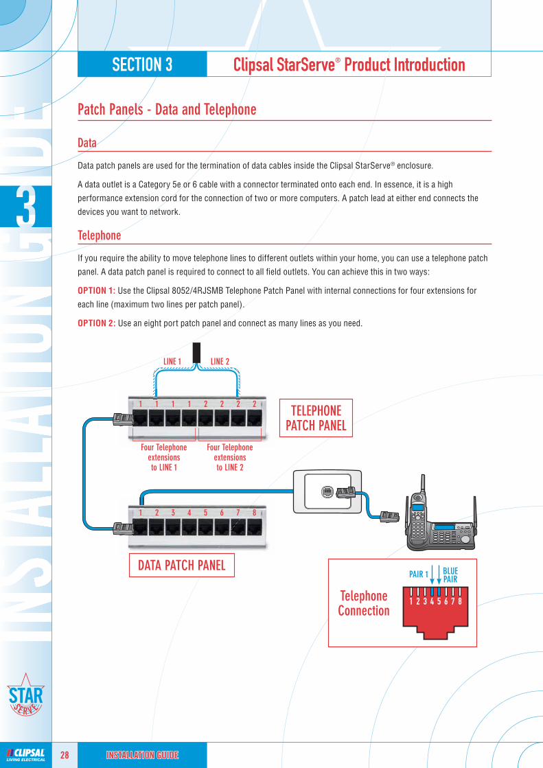
Patch Panels - Data and Telephone
Data
Data patch panels are used for the termination of data cables inside the Clipsal StarServe® enclosure.
A data outlet is a Category 5e or 6 cable with a connector terminated onto each end. In essence, it is a high
performance extension cord for the connection of two or more computers. A patch lead at either end connects the
devices you want to network.
Telephone
If you require the ability to move telephone lines to different outlets within your home, you can use a telephone patch
panel. A data patch panel is required to connect to all fi eld outlets. You can achieve this in two ways:
OPTION 1: Use the Clipsal 8052/4RJSMB Telephone Patch Panel with internal connections for four extensions for
each line (maximum two lines per patch panel).
OPTION 2: Use an eight port patch panel and connect as many lines as you need.
1 2 3 4 5 6 7 8
1 1 1 1 2 2 2 2
LINE 1 LINE 2
TelephoneConnection
PAIR 1 BLUEPAIR
TELEPHONEPATCH PANEL
DATA PATCH PANEL
Four Telephone extensionsto LINE 1
Four Telephone extensionsto LINE 2

SECTION 3 Clipsal StarServe® Product Introduction
29INSTALLATION GUIDEINSTALLATION GUIDEINSTALLATION GUIDE
Switches - Data Patch Panels
A switch connects two or more computers together so that they can communicate with each other.
1 2 3 4 5 6 7 8
1
3
6
Any computer can network with other computers connected to the switch.
Network printers can be connected so everyone on the network can use one printer.
PC
PC
Network printer(Ethernet connection)
DATA PATCH PANEL
95ESW5P10/5-Port Ethernet Switch
95ESW8P10/8-Port Ethernet Switch

SECTION 3 Clipsal StarServe® Product Introduction
30 INSTALLATION GUIDEINSTALLATION GUIDEINSTALLATION GUIDE
The output expander allows you to increase the number of Clipsal StarServe®
outputs without the use of an additional video hub. It consists of one input
and four outputs.
Connect an output of your existing video hub to the input of the expander.
You will lose the use of an output on the video hub but gain an additional four
outputs on the output expander.
You can connect an output expander to each output on a video hub, providing
up to 32 outputs from an eight input hub.
Output Expander8001/4EX
The IR injector allows you to insert an IR target anywhere along the RG6
cable feed between the Clipsal StarServe® video hub and the TV. This means
a target can be placed away from the TV screen to eliminate interference
from the TV or plasma screen.
The IR injector can be used with a tube (8050TT), fl at (8050FT) or shelf
(8050ST) target.
IR Injector8000INJ
F-Type fl y lead
F-Type to PAL fl y lead
8050FTFlat Target
Plasma TVWallplate
8000INJIR Injector
8050TTTube Target
8050STShelf Target
8050FTFlat Target

SECTION 3 Clipsal StarServe® Product Introduction
31INSTALLATION GUIDEINSTALLATION GUIDEINSTALLATION GUIDE
This adaptor allows you to transmit standard video and audio signals, as
well as DC power over Category 5 or Category 5e cable. An RCA to Category
5 cable adaptor is used at each cable end, making it suitable for security
camera installations integrated with Clipsal StarServe®.
The 8000AVB has two baluns and one power lead supplied in each pack (one
for either end of the cabling network).
RCA to Cat-5 Cable Adaptor8000AVB
The DC block is used to fi lter out DC Voltage and infrared (IR) control pulses
on a Clipsal StarServe® RG6 cable feed. It is inserted in an individual cable
feed. It contains a capacitor which allows high frequency video and audio to
pass, but blocks DC and low frequency IR.
The 8000DCB is recommended when an amplifi er is connected to the input
“ANT INPUT” on any StarServe VDU.
Coaxial DC Block8000DCB
Refer to page 52 for wiring connection
details.
Refer to page 41 for wiring connection
details.

SECTION 4 Minimum TV Cabling Requirements
32 INSTALLATION GUIDEINSTALLATION GUIDEINSTALLATION GUIDE
TV Cabling Requirements
All TV cabling is run using RG6 Quad Shield Coax Cable. The RG6 Quad Shield Coax has excellent shielding against
electrical noise, which can affect picture quality.
The Clipsal Quad Shield Coax Cable is FOXTEL approved. The use of a top quality coax cable will greatly minimise
any call-backs for the electrical contractor.
MATV Tools Required
To perform a Clipsal StarServe® installation quickly and effectively you require the right tools for the job.
F-Type Connectors
F-Type connectors are the best connectors to use in an MATV installation. F-Type connectors have very low losses
and are easy to connect. Clipsal recommend two types of F-Type connectors on a Clipsal StarServe® System, the
Radial Crimp 3105RG6F or the Compression Connector 3105RG6FC50.
3105RG6FRadial Crimp
3105PM-FFF-Type Female Adaptor
to Male PAL
3105RG6FC50Compression Connector
To make up good quality fl y leads on site, Clipsal recommend the use of F-Type to PAL adaptors.
3105RG6Q3BRG6 Quad Shield Coax Cable
3105CS6Cable Stripper to suit
RG6 Quad Shield
3105CT611Crimper for Radial Crimp F-Type connection
3105CT611CCompression tool to suit F-Type compression connectors
3105CRFTKMATV Compression Toolbox

SECTION 4 Minimum TV Cabling Requirements
33INSTALLATION GUIDEINSTALLATION GUIDEINSTALLATION GUIDE
TV Fly Leads
Clipsal has F-Type to PAL fl y leads in its range to suit Clipsal StarServe® installations.
Fly leads are the weakest point in any TV system. Fly leads are subjected to being twisted and tangled with power
cords behind TV entertainment units. Using RG6 quad shield coax fl y leads will minimise any potential problems
occurring and reduce any potential call-backs.
Fly leads can be manufactured on site by a MATV contractor or purchased as a fi nished product.
TV Mechs
The Clipsal 30PFM and 30FFPFMS are straight through connectors. These connectors have excellent electrical
performance and minimal losses. These connectors allow IR to pass through for the remote control IR engine built
into the Clipsal StarServe® VDU’s 3105VDU38IRT and 8073/8VHPIR.
Digital Terrestrial Meter
A digital terrestrial meter is used to measure the signal strength of a MATV System. This is one of the most important
tools you can own, as it will save you lots of time and money. Instead of guessing the antenna direction and signal
strength you can accurately align the antenna and measure the signal strength.
Failure to use either of these items may
result in the infrared control to fail.
30PFMF-Type Connectors
3105FL318MWQF-Type to PAL Fly Lead
(White)
3105FL318MBQF-Type to PAL Fly Lead
(Black)
2ANDTMDigital Terrestrial Meter
30FFPFMSF-Type to PAL Connectors

SECTION 4 Minimum TV Cabling Requirements
34 INSTALLATION GUIDEINSTALLATION GUIDEINSTALLATION GUIDE
Conventional TV Cabling
Only one TV can view DVD, subscription TV or video at one time.
SECTION 4 Minimum TV Cabling Requirements
35INSTALLATION GUIDEINSTALLATION GUIDEINSTALLATION GUIDE
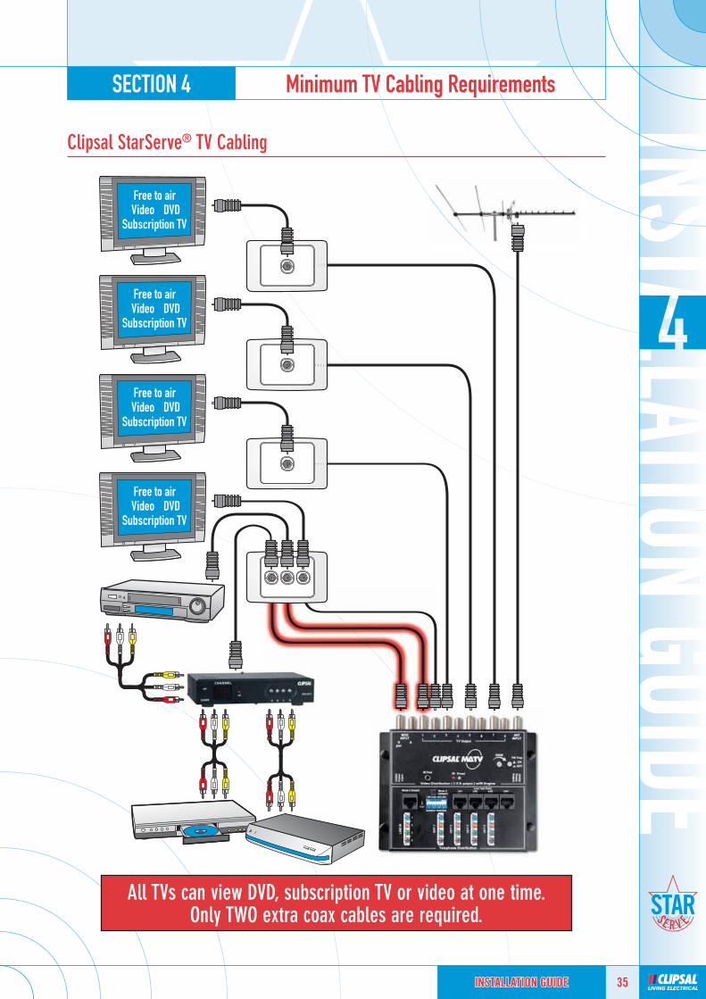
Clipsal StarServe® TV Cabling
All TVs can view DVD, subscription TV or video at one time.Only TWO extra coax cables are required.

SECTION 4 Minimum TV Cabling Requirements
36 INSTALLATION GUIDEINSTALLATION GUIDEINSTALLATION GUIDE
TV Wiring Diagram3105VDU38IRT
B 1 2
4
Location:MASTER BEDROOM
3
Location:BEDROOM 2
6
Location:BEDROOM 3
5
Location:BEDROOM 4
7
Location: STUDY
8
Location: OTHER
Wallplate locatedin your MAIN
ENTERTAINMENT AREA
Refer to page 22-24 for VDU powering
options.
Note: 3105VDU38IRT can support IR control with the addition of 8050TR, 8050LD and StarServe modulators
with IR.
VCR and Modulator must be within one meter of each other for IR emitter lead.

SECTION 4 Minimum TV Cabling Requirements
37INSTALLATION GUIDEINSTALLATION GUIDEINSTALLATION GUIDE
TV Wiring Diagram3105VDU24T
B 1 2
3
Location:MASTER
BEDROOM
4
Location:BEDROOM 2Wallplate located
in your MAIN ENTERTAINMENT AREA
Refer to page 22-24 for VDU powering
options.
Note: The 3015VDU24T does not support IR control.

SECTION 4 Minimum TV Cabling Requirements
38 INSTALLATION GUIDEINSTALLATION GUIDEINSTALLATION GUIDE
TV Wiring Diagram8073/8VHPIR
B 1 2
Location:MASTER BEDROOM
Location:BEDROOM 2
Location:BEDROOM 3
Location:BEDROOM 4
Location: STUDY Location: OTHER
34
6 5
7 8
Wallplate locatedin your MAIN
ENTERTAINMENT AREA
Refer to page 22-24 for VDU powering
options.
Note: 3105VDU38IRT can support IR control with the addition of 8050TR, 8050LD and StarServe modulators
with IR.
VCR and Modulator must be within one meter of each other for IR emitter lead.
SECTION 4 Minimum TV Cabling Requirements
39INSTALLATION GUIDEINSTALLATION GUIDEINSTALLATION GUIDE
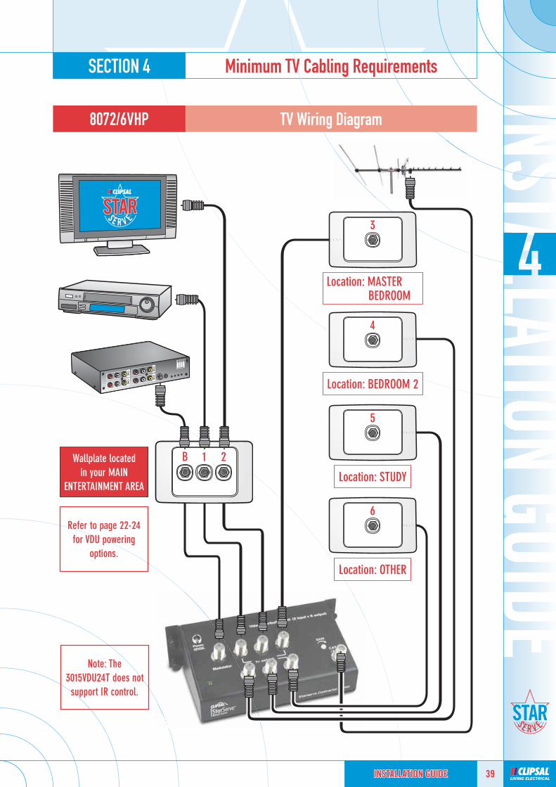
TV Wiring Diagram8072/6VHP
B 1 2
Location: MASTER BEDROOM
4
Location: BEDROOM 2
5
Location: STUDY
6
Location: OTHER
3
Wallplate locatedin your MAIN
ENTERTAINMENT AREA
Refer to page 22-24 for VDU powering
options.
Note: The 3015VDU24T does not support IR control.

SECTION 5 Video Distribution - How to Connect
40 INSTALLATION GUIDEINSTALLATION GUIDEINSTALLATION GUIDE
Antenna Input
The antenna input of the Video Distribution Unit (VDU) has an F-Type connection. The Clipsal StarServe® VDU has
built in gain control to enable the optimum signal level to be achieved easily with the turn of a screw.
The range of variable gain control is +5dBuV gain (increase) from incoming signal or –15 dBuV attenuation (loss).
The optimum level of signal strength on the output ports of the VDU is 72dBuV.
This means that a minimum signal level of 69dBuV is required at the antenna input (a small margin is allowed for variation between signals).
The maximum signal level that can be connected to the antenna input is 89dBuV.
Step 1
Measure the incoming signal from the antenna. If the signal is between 69 - 89dBuV, you can connect to the Clipsal
StarServe® VDU via the antenna input. If the signal strength is below 69dBuV, you will need to EITHER replace the
antenna with a larger model OR use an amplifi er to increase the signal strength.
If the signal strength is over 89dBuV, you will have to attenuate the signal via a drop tap (3105T Series).
Step 2
Measure the signal strength from the VDU output. Adjust the variable gain control until you reach 72dBuV.
69dBuVminimum
The modulator input signal strength must be within 15dBuV of the output
free to air signal.It is ideal to get the signal levels as close as possible.

SECTION 5 Video Distribution - How to Connect
41INSTALLATION GUIDEINSTALLATION GUIDEINSTALLATION GUIDE
Antenna Input – Using an amplifi er with the Clipsal StarServe® VDU
If you are using an amplifi er with Clipsal StarServe® Video Distribution you must follow these strict requirements
otherwise you may cause damage to the VDU.
• A DC block must be used on the antenna input to the VDU. This will stop any power being supplied to the VDU that
can cause damage to the VDU.
• The masthead amplifi er must be powered before the connection to the DC block.
Step 1
Measure the incoming signal from the amplifi er. If the signal is between 69 - 89dBuV, you can connect to the Clipsal
StarServe® VDU via the antenna input.
If the signal strength is over 89dBuV, you will have to attenuate the signal via a drop tap (3105T Series).
Step 2
Measure the signal strength from the VDU output. Adjust the variable gain control until you reach 72dBuV.
Note: If the incoming signal strength is too high then a drop
tap may be used to attenuate the signal strength to achieve the desired level 69 – 89dBuV.
Mastheadamplifi er
Masthead amplifi erpower supply
Amplifi erT-Piece
DC Block - 8000DCB
Power Outlet
SECTION 5 Video Distribution - How to Connect
42 INSTALLATION GUIDEINSTALLATION GUIDEINSTALLATION GUIDE
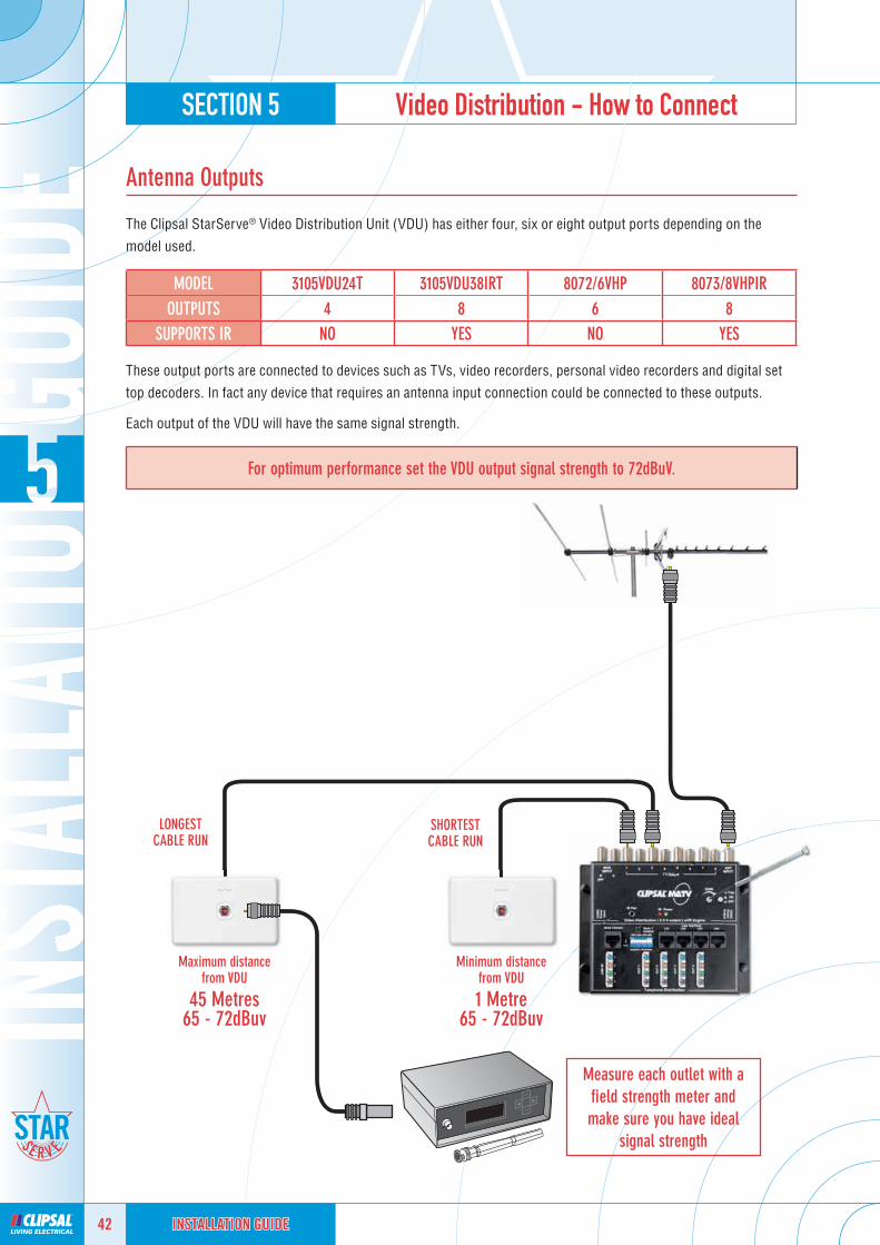
Antenna Outputs
The Clipsal StarServe® Video Distribution Unit (VDU) has either four, six or eight output ports depending on the
model used.
MODEL 3105VDU24T 3105VDU38IRT 8072/6VHP 8073/8VHPIROUTPUTS 4 8 6 8
SUPPORTS IR NO YES NO YES
These output ports are connected to devices such as TVs, video recorders, personal video recorders and digital set
top decoders. In fact any device that requires an antenna input connection could be connected to these outputs.
Each output of the VDU will have the same signal strength.
For optimum performance set the VDU output signal strength to 72dBuV.
Maximum distance from VDU
45 Metres65 - 72dBuv
Minimum distancefrom VDU
1 Metre65 - 72dBuv
Measure each outlet with a fi eld strength meter andmake sure you have ideal
signal strength
SHORTESTCABLE RUN
LONGESTCABLE RUN
SECTION 5 Video Distribution - How to Connect
43INSTALLATION GUIDEINSTALLATION GUIDEINSTALLATION GUIDE
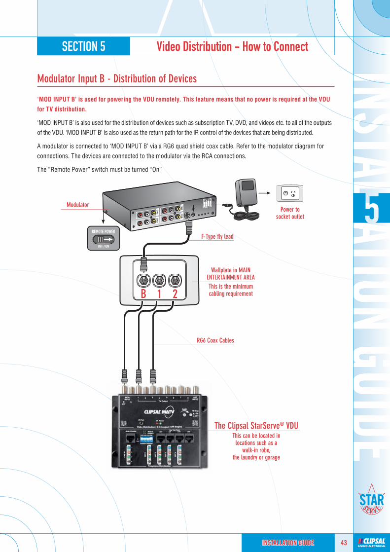
Modulator Input B - Distribution of Devices
‘MOD INPUT B’ is used for powering the VDU remotely. This feature means that no power is required at the VDU
for TV distribution.
‘MOD INPUT B’ is also used for the distribution of devices such as subscription TV, DVD, and videos etc. to all of the outputs
of the VDU. ‘MOD INPUT B’ is also used as the return path for the IR control of the devices that are being distributed.
A modulator is connected to ‘MOD INPUT B’ via a RG6 quad shield coax cable. Refer to the modulator diagram for
connections. The devices are connected to the modulator via the RCA connections.
The “Remote Power” switch must be turned “On”
B 1 2
Modulator
F-Type fl y lead
Power tosocket outlet
Wallplate in MAIN ENTERTAINMENT AREAThis is the minimum cabling requirement
RG6 Coax Cables
The Clipsal StarServe® VDUThis can be located in
locations such as awalk-in robe,
the laundry or garage

SECTION 5 Video Distribution - How to Connect
44 INSTALLATION GUIDEINSTALLATION GUIDEINSTALLATION GUIDE
Setup of the Modulator
The back of the modulator has four sets of RCA inputs for active devices such as subscription TV decoders, DVDs, DVRs,
etc. The CH refers to the modulator channel input. The input is indicated on the front of the modulator by the letters
A – B – C – D.
Before you program a UHF channel you must make sure that the UHF frequency is not being used in your region. If
UHF frequencies are being used in your region, you must have at least two-channel separation from the broadcasted
channels. The reason for this is that the signals can spill over to adjacent channels resulting in poor picture quality
for adjacent channels.
Example: SBS is broadcast on UHF 33 - you cannot use channel 32, 33, 34, but you can use channel UHF 35.
• Step 1: Select the input CH A, B, C or D you wish to set.
• Step 2: Use the up and down push buttons to select the UHF channel you require. The channel will be displayed in
the channel window next to the up and down push buttons.
• Step 3: Push the select button again and repeat the process for other input CHs. Your UHF channel has now been
programmed. You will need to do an auto search on your TV to tune into these new channels.
C
D
B
A
Use the UP and DOWN push buttons to select
the UHF channel required
The screen will indicate the UHF channel the selected input will be broadcast on
Push select button to change fromA, B, C and D
Available channelsare UHF 21-69
STEP 2 STEPS 1 & 3
The Modulator must be located in the same location as your DVD, subscription TV decoder and video.

SECTION 5 Video Distribution - How to Connect
45INSTALLATION GUIDEINSTALLATION GUIDEINSTALLATION GUIDE
Modulator AV Connections
Connection of an AV device such as a DVD to the modulator requires a set of AV leads.
8071VMP (MONO)* 8071VMS (STEREO)
8072VMPIR (MONO) 3105M2SIR (STEREO)
8074VMPIR (MONO)3105M4SIR (STEREO)
Connection of ONE device with
IR capability
*No IR capability
Connection of TWO devices with
IR capability
Connection of FOUR devices with
IR capability
3105AVL318HQVideo Leads
Modulator

SECTION 5 Video Distribution - How to Connect
46 INSTALLATION GUIDEINSTALLATION GUIDEINSTALLATION GUIDE
Modulator AV Connections - Y Lead Connections
Y leads are used to connect one device (subscription TV decoder) to two different devices (TV and modulator).
If you are using Y leads to a device to the AV input of you television and to the AV inputs on the modulator, you need to
change the position of the Hi-Z dip switches from 75 OHM to Hi-Z for the modulator channel you are splitting. This will
allow the loop through with minimal losses.
If using Y Leads, the Hi-Z Dip Switches need to be switched from
75 Ohm to Hi-Z
TV
Video connected to TV,audio connected to TV
or surround sound system
DVD player
8074VMPIRModulator

SECTION 5 Video Distribution - How to Connect
47INSTALLATION GUIDEINSTALLATION GUIDEINSTALLATION GUIDE
IR Emitter Leads
The IR emitter leads (or repeaters) are plugged into the modulator. The head of the IR emitter lead is to be fi xed over the
IR receiver of the device that is to be remotely controlled with the sticky backing provided on the emitter head.
The emitter head will allow the pass through of IR signals from the remote control so the device can operate normally
from the room that it is in.
Device
8074VMPIRModulator
To locate the IR pickup of the device you wish to control, placeyour thumb over the suspected location of the IR pickup.
Use the remote control to change channels, fast forward or skip.When you cannot change the status of the device,
you are directly over the IR pickup.Note the location and stick the IR emitter lead into position.
The IR system will only work when the remote power switch is in the ON position.

SECTION 5 Video Distribution - How to Connect
48 INSTALLATION GUIDEINSTALLATION GUIDEINSTALLATION GUIDE
IR Target
Connection of the IR target is a simple process.
You will require a F-Type to F-Type fl y lead to connect the wall outlet to the IR target. (The back of the IR target is
marked ‘From System’). You can use the existing F-Type to PAL fl y lead from the IR target to the TV. (The back of the IR
Target is market “TO TV”). The IR Target can then be placed onto the TV and stuck down with double sided tape or velcro.
Clipsal recommends you only use a 30PFM Socket at the wall outlet. This socket is digital ready and does not have AC
isolation or a capacitor that will block the IR signal. Failure to use the 30PFM may result in no IR control of devices.
If installing IR targets with plasma screen TVs, you must locate the IR target BELOW the screen.
Plasma screens emit radiation that can drown out IR frequencies. You may need to adjust the
location of the IR target on-site,depending on the plasma screen.
30PFMin wallplate TV
F-Type fl y lead
Infrared target
REAR OF TARGET
F-Type to PALfl y lead
The Clipsal StarServe® VDU
The Starserve System must be powered down when installing
targets. IR targets will not initialise (start working) until the system is
turned “off” then “on”.

SECTION 5 Video Distribution - How to Connect
49INSTALLATION GUIDEINSTALLATION GUIDEINSTALLATION GUIDE
IR Control of Devices
To remotely control devices from other rooms of your home you will need to use the products that have IR capability.
F-Type fl y lead
F-Type fl y lead
F-Type fl y lead
F-Type fl y leadTV
F-Type to PALfl y lead
IR emitter lead
Device
Infrared target
The Clipsal StarServe® VDU Refer to page 22-24 for VDU powering
options.

SECTION 5 Video Distribution - How to Connect
50 INSTALLATION GUIDEINSTALLATION GUIDEINSTALLATION GUIDE
Modulator Input A - Single Surveillance Camera
‘MOD INPUT A’ is used for devices not requiring IR remote control such as surveillance cameras. A modulator is connected
to ‘MOD INPUT A’ via a RG6 quad shield coax cable. Refer to the modulator diagram below for connection details.
The camera is connected to the modulator via the RCA connections. This enables the camera to be viewed from any
TV connected to a Clipsal StarServe® VDU output.
Things to consider:
• Location of modulator – where are you going to put it?
• How are you going to power the camera – locally or remotely?
• How many cameras are you going to have – how many channels do you require?
Single camera modulated
throughInput ‘A’
Modulator
F-Type to RCA adaptor
F-Type connector
RG6 QuadCoax Cable
F-Type to RCA adaptor
F-Type connector to either an RCA or BNC adaptor
F-Type to BNC adaptor
A one-piece connector provides the best quality connection of devices.An adaptor is suitable for the majority of installations.
Refer to page 22-24 for VDU powering
options.

SECTION 5 Video Distribution - How to Connect
51INSTALLATION GUIDEINSTALLATION GUIDEINSTALLATION GUIDE
Modulator Input A - Multiple Surveillance Cameras
Where multiple cameras are needed, a two or four channel modulator is required.
8072VMPIR – Two Channel Modulator 8074VMPIR – Four Channel Modulator (Pictured)
3105FF-RCAF-Type Female to RCA Male Adaptor
3105FF-BNCF-Type Female to BNC Male Adaptor
Four cameras modulated
throughInput ‘A’
Refer to page 22-24 for VDU powering
options.
SECTION 5 Video Distribution - How to Connect
52 INSTALLATION GUIDEINSTALLATION GUIDEINSTALLATION GUIDE
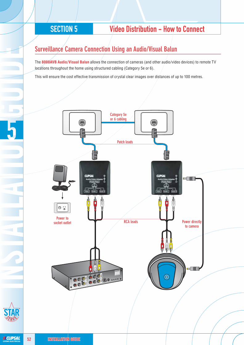
Surveillance Camera Connection Using an Audio/Visual Balun
The 8000AVB Audio/Visual Balun allows the connection of cameras (and other audio/video devices) to remote TV
locations throughout the home using structured cabling (Category 5e or 6).
This will ensure the cost effective transmission of crystal clear images over distances of up to 100 metres.
Category 5eor 6 cabling
Patch leads
Power tosocket outlet RCA leads Power directly
to camera

SECTION 6 Phone/Data Minimum Cabling Requirements
53INSTALLATION GUIDEINSTALLATION GUIDEINSTALLATION GUIDE
Telephone/Data Cabling
Clipsal StarServe® uses Category 5e or Category 6 cabling for all telephone, internet, data networking and video
distribution. The part numbers required for the Clipsal solution are as follows:
2D4P5IPV3B,BUCategory 5e UTP cable
2D4P6IPV3B,BUCategory 6 UTP cable
95ESW5P10/
95ESW8P10/
Add one of these
data switches to connect
a data network
within your home.
Patch Leads
Clipsal patch leads are available in Category 5e and Category 6 and come
in several different colours and lengths. Clipsal produce specially made 0.2
metre patch leads for Clipsal StarServe®.
Required Data Tools
The termination of the data cabling must be done with a Clipsal / Krone type
tool. A cable stripper must be used to strip the sheath of the category cable
to avoid the cutting of the conductors, which will affect the performance of
the installation.3100RJA5VPunchdown Tool
Patch Panels
Ethernet Switches
FOR LIGHT AND MID SIZE ENCLOSURES FOR PROFESSIONAL ENCLOSURES8052/4RJSMB 8058/8RJSMB RJ88SMA5 RJ88SMA6
TELEPHONE PATCH PANEL2 LINES IN, 4 LOCATION PER LINE
DATA 8 PORT PATCH PANEL(8 OUTLETS)
CAT 5eKEYSTONE
CAT 6KEYSTONE
8052/4RJSMB
OR 3105ATPP2X4 OR 3105APP8/5E
ZE ENCLOSURES8058/8RJSMB

SECTION 6 Phone/Data Minimum Cabling Requirements
54 INSTALLATION GUIDEINSTALLATION GUIDEINSTALLATION GUIDE
Recommended Cabling for Telephone and Data Requirements
TELEPHONE/INTERNET
One cable for TelephoneOne cable for Internet
TELEPHONE/DATA/PRINTER
One cable for TelephoneOne cable for Data
One cable for a Printer
TELEPHONE
One cable per Telephone
PHONE
INT TEL DATA
3105PENFProfessionalEnclosure
One cable connected to an outlet per
application
DATATEL
• TELEPHONE• INTERNET• DATA

SECTION 7 Telephone/Internet - How to Connect
55INSTALLATION GUIDEINSTALLATION GUIDEINSTALLATION GUIDE
Telephone Connection
PHONE
Line 1
PHONE
Line 1
PHONE
Line 1
PHONE
Line 1
Connect the incoming telephone line to LINE 1 of the telephone punchdown card.
The line is now internally connected to all the blue pair connectors.
Use the Line Test Point RJ sockets to test the telephone line by pressing theLine Test Point switch to ‘TEST’.
Make sure you reset the test switch to enable the telephone line to beconnected to the outlet.
Incoming telephone
line connects
to LINE 1
A total of
4telephone outlets can
be connected
to LINE 1
You must have the appropriate licenses for telephone cabling installation to connecttelephone cabling to Clipsal StarServe®

SECTION 7 Telephone/Internet - How to Connect
56 INSTALLATION GUIDEINSTALLATION GUIDEINSTALLATION GUIDE
Jumpering Telephone Outlets
Use excess wire as jumper wire from LINE 1 to LINE 2: this doubles the number of telephone outlets available
PHONE
Line 1
PHONE
Line 1
Telephone outlets can now be connected to either the
BLUE or ORANGE pairs
When jumpering LINE 1 to extend the number of telephone outlets, you must do it on the outlet side so as to not compromise the Mode 3 functionality.
The number of telephones that can be connected to any telephone line is determined by the REN of the phone (Ring Extension Number). To determine your phones “REN” value look at
the bottom of your phones for their values, then add them together.
A total of
8telephone
outlets can be connected to
LINE 1
Incoming telephone
line connects
to LINE 1

SECTION 7 Telephone/Internet - How to Connect
57INSTALLATION GUIDEINSTALLATION GUIDEINSTALLATION GUIDE
Mode 3 Security System Connection
SECURITY SYSTEM
Two pair telephone cable fl y lead to
alarm dialler
When connecting to the alarm panel, the MODE 3 JUMPERS
need to be REMOVED to make the telephone connection.
NOTE: the MODE 3 JUMPERS must be kept inside the enclosure in case the Alarm System Dialler
needs to be removed.
Incoming telephone line connects to
LINE 1
The alarm panel connects through a Mode 3 socket.
When the alarm panel is triggered into alarm mode, it automatically cuts off all the other telephone extensions and dials out to the monitoring service.
The Mode 3 socket is the fi rst connection.

SECTION 7 Telephone/Internet - How to Connect
58 INSTALLATION GUIDEINSTALLATION GUIDEINSTALLATION GUIDE
ADSL Connection
ADSL FILTERADSL PHONE
Incoming telephone line
Incoming telephone line
connects to
LINE 1
ADSLmodem line connects to
LINE 4
ADSL PHONE
ADSL PHONE
ADSL PHONE
ADSL PHONE
Run a CATEGORY 5 CABLE to the location of the wall plate. Connect LINE 1 (PHONE) to ONE OUTLET and LINE 4 (ADSL) to another outlet.
Phone and internet access can be obtained at multiplewall outlets with only ONE ADSL FILTER.
NOTE: only ONE ADSL OUTLET can be used at ONE TIME. A SWITCH MODEM ROUTER is required if you require simultaneous ADSL links.

SECTION 7 Telephone/Internet - How to Connect
59INSTALLATION GUIDEINSTALLATION GUIDEINSTALLATION GUIDE
ADSL Connection with Jumpering Leads
ADSL FILTERADSL PHONE
Incoming telephone line
Incoming telephone line
connects to
LINE 1
ADSLmodem line connects to
LINE 4
ADSL PHONE
ADSL PHONE
A jumper cable is only required on one outlet
extension.
This will internally connect all outputs to the same line for
jumpered pairs.
Run a CATEGORY 5 CABLE to the location of the wall plate. Connect LINE 1 (PHONE) to ONE OUTLET and LINE 4 (ADSL) to another outlet.
Phone and internet access can be obtained at multiplewall outlets with only ONE ADSL FILTER.
NOTE: only ONE ADSL OUTLET can be used at ONE TIME. A SWITCH MODEM ROUTER is required if you require simultaneous ADSL links.

SECTION 7 Telephone/Internet - How to Connect
60 INSTALLATION GUIDEINSTALLATION GUIDEINSTALLATION GUIDE
ADSL Switch Modem Router Connection
8
ADSL
1 2 3 4
12V DC
ADSL FILTERADSL PHONE
Incoming telephone line
Switch modem router powered
from VDU
Telephone patch lead from ADSL input on modem router to LINE 4 on the VDU
Push TEST buttonon LN4 to
‘TEST’ position.
1 2 3 4 5 6 7 8
1
A switch modem router allows for multiple users to access
the Internet at the same time.
8-PORT PATCH PANEL

SECTION 8 Data Cabling - How to Connect
61INSTALLATION GUIDEINSTALLATION GUIDEINSTALLATION GUIDE
Patch Panel Setup - Data Cabling
Data cabling is simply a cable connecting two data outlets together to make a ‘data extension cord’. One outlet is
installed into a wall plate and the other is located in a panel alongside a number of other outlets.
The connection of the data outlets are the same at both ends.
DATA 1
DATA 2
DATA 3
DATA 4
DATA 8
DATA 7
DATA 6
DATA 5
1 2 3 4 5 6 7 8
PC PCPrinter

SECTION 8 Data Cabling - How to Connect
62 INSTALLATION GUIDEINSTALLATION GUIDEINSTALLATION GUIDE
Patch Panel Connection for Structured Cabling System
The telephone patch panel is a simple connection that performs the same function as the telephone card on the
combination VDU.
You terminate one telephone line to obtain four outlets for that line. The connections are made internally as part of
the circuit board. There are two termination points for two incoming telephone lines and four extensions for each
incoming line.
To patch a telephone line to an outlet, you will need to use a patch lead. Plug the patch lead into the telephone line you
require (Line 1 or 2). Then plug the other end of the lead into the data patch panel outlet that is connected to the outlet
you want to convert into a telephone line.
PATCH PANEL/ENCLOSURE COMPATIBILITY CHART
3105ABEN 8000LEN 8000MEN 3105PENF 3105PENS
Data Angled Patch Panels3105APP8/5E ✔ ✔ ✔ ✔ ✔3105APP8/6 ✔ ✔ ✔ ✔ ✔
Telephone Patch Panels8052/4RJ ✘ ✘ ✘ ✘ ✘
8052/4RJSMB ✘ ✔ ✔ ✘ ✘8052/4RJDMB ✘ ✘ ✔ ✘ ✘
Data Patch Panels8058/8RJ ✘ ✘ ✘ ✘ ✘
8058/8RJSMB ✘ ✔ ✔ ✘ ✘8058/8RJDMB ✘ ✘ ✔ ✘ ✘
1 2 3 4 5 6 7 8
1 1 1 1 2 2 2 2TELEPHONE
PATCH PANEL
DATAPATCH PANEL
Data outlet used as a telephone outlet
LINE 1 LINE 2
1
4 telephone extensionsto LINE 1
4 telephone extensionsto LINE 2

SECTION 8 Data Cabling - How to Connect
63INSTALLATION GUIDEINSTALLATION GUIDEINSTALLATION GUIDE
Telephone Distribution using a Telephone Patch Panel
By using a telephone patch panel you can distribute two incoming telephone lines to four locations for each incoming
line. You can also move your telephone outlets as often as you require by patching across to a different outlet.
For your customers who want to be able to patch across their telephone lines this is an excellent way to do it.
The telephone patch panel is internally connected to a single punch down block on the back of the panel. One
termination can connect four extensions for that line. You must have an additional data patch panel for this to work.
1
2
3
4
8
7
6
5
1 2 3 4 5 6 7 8
1 1 1 1 2 2 2 2TELEPHONE
PATCH PANEL
DATAPATCH PANEL
TELEPHONE INTERNET
TELEPHONE
TELEPHONE
INTERNET

SECTION 9 Subscription TV Cabling Requirements/Overview
64 INSTALLATION GUIDEINSTALLATION GUIDEINSTALLATION GUIDE
FOXTEL IQ Cabling Requirements - Single Outlet Domestic
FOXTEL require two FOXTEL approved RG6 Quad Shield Coax Cables run from the satellite dish mounted on the roof
to the location of the FOXTEL decoder (3105RG6Q3B).
The cables must be connected with FOXTEL approved F-Type Compression Connectors (3105RG6FC50). The cables
must connect to FOXTEL approved TV mechanisms (30PFM). A telephone outlet is required for the inbuilt modem of
the FOXTEL IQ decoder for communication back to FOXTEL for pay per view functions and billing.
Run a category or telephone cable from the Clipsal StarServe® to the FOXTEL wall plate and terminate to the main
telephone line.
FOXTEL provide an approved parts list available through their internet site. Please refer to this for all
FOXTEL installations.
Two additional cables can be run from the dish to the roofspace for future use.
Satellite dish
RG6 Quadshield Cables
For more information or technical queries please call FOXTEL on 1300 136 488 or visit FOXTEL.com.au
FOX 1 FOX 2
MODEMFTA

SECTION 9 Subscription TV Cabling Requirements/Overview
65INSTALLATION GUIDEINSTALLATION GUIDEINSTALLATION GUIDE
AUSTAR Cabling Requirements - Single Outlet Domestic
AUSTAR require two AUSTAR approved RG6 Quad Shield Coax Cables run from the satellite dish mounted on the roof
to the location of the AUSTAR decoder (3105RG6Q3B).
The cables must be connected with AUSTAR approved F-Type Compression Connectors (3105RG6FC50). The cables
must connect to AUSTAR approved TV mechanisms (30PFM). In the future a telephone outlet is required for the
inbuilt modem of the AUSTAR decoder for communication back to AUSTAR for pay per view functions and billing.
Run a category or telephone cable from the Clipsal StarServe® to the AUSTAR wall plate and terminate to the main
telephone line.
AUSTAR provide an approved parts list available through their internet site. Please refer to this for all
AUSTAR installations.
Satellite dish
RG6 Quadshield Cables
Two additional cables can be run from the dish to the roofspace for future use.
For more information or technical queries please call the AUSTAR Multi Dwelling Unit on 1300 736 747 or e-mail [email protected]
AUS 1 AUS 2
MODEMFTA

SECTION 9 Subscription TV Cabling Requirements/Overview
66 INSTALLATION GUIDEINSTALLATION GUIDEINSTALLATION GUIDE
Multiple Subscription TV Decoder Cabling Requirements - Domestic Installations
For multiple subscription TV outlets you will require a device called a multiswitch. The two cables from the satellite
dish connect to the inputs of the multiswitch.
The two cables required by the subscription TV companies at the wall plate are then connected to the multiswitch
outputs. The multiswitch is powered via the subscription TV decoder. Multiswitches are available in a number of
confi gurations depending on the number of subscription TV outlets required (eg: four, eight, twelve outputs).
A telephone outlet is required for the inbuilt modem of the subscription TV decoder for communication back to the
subscription TV provider for pay per view functions and billing.
Run a category or telephone cable from the Clipsal StarServe® to the subscription TV wall plate and terminate to the
main telephone line.
Must be earthed in compliance with
AS/NZS 1367, AS/NZS3000& AS/ACIF S009
Satellite dish
RG6 Quadshield Cables
2 In/8 Out Multiswitch
Clipsal is now offering you access to a comprehensive commercial MATV design and comissioning service. For more information please call Clipsal on 1800 728 728.
PAY 1 PAY 2
MODEMFTA
PAY 1 PAY 2
MODEMFTA
PAY 1 PAY 2
MODEMFTA

SECTION 9 Subscription TV Cabling Requirements/Overview
67INSTALLATION GUIDEINSTALLATION GUIDEINSTALLATION GUIDE
Apartment Cabling Requirements - Commercial Installations
When cabling subscription TV into multistorey apartments you must cable from the riser to the apartment
subscription TV location, 2 x subscription TV approved cables to the wall plate.
A telephone cable must be run from the Clipsal StarServe® to the subscription TV wall plate for subscription TV
company’s minimum cabling requirements.
Clipsal is now offering you access to a comprehensive commercial MATV design and comissioning service. For more information please call Clipsal on 1800 728 728.
PAY 1 PAY 2
MODEM
Wallplate located in apartment
2 In/4 Out Multiswitchlocated in riser
H1V1
Multiswitches must be earthed in compliance withAS/NZS 1367, AS/NZS3000
& AS/ACIF S009
Clipsal StarServe® VDU located in apartment
RG6 Quadshield Cables
Subscription TV decoder
FTA

SECTION 10 Cabling Considerations
68 INSTALLATION GUIDEINSTALLATION GUIDEINSTALLATION GUIDE
Key Area 1 - The Lounge Room
The fi rst key area is the location where the active devices such as the subscription TV decoder, DVD, VCR / DVR are
located. The reason this is important is because we need to supply the DVR with a separate TV input so that the DVR can
record without affecting the television in that room. The television in that room must also have a separate TV input.
To view the active devices in other rooms, the signals from these devices must be sent back to the Clipsal StarServe®
VDU to be combined with the free to air signals going to the TV sets throughout the home. This then enables all the
TV sets to view free to air TV plus DVD, DVR and subscription TV decoder signals.
A data outlet is required for technologies such as media centres that enable your computer to interact with your TV
and stereo system.
Typical Locations
The lounge room is a typical location for all of these devices and
probably the most popular. In the home we generally have all active
devices in the lounge room, as it provides easy access to DVDs or
watching subscription TV.
In some homes, the practice is to hide the active equipment in
cupboards. As plasma screens become more affordable homeowners want to make it a feature on the wall and hide
all the cables and boxes away from sight. Either way, you must have the cabling in the right location.
Future Distribution of Services
Along with the standard wall plate you will require an additional four
data cables on a separate wall plate. These four data cables are for the
future distribution of video services.
This wall plate is highly recommended as the benefi ts of installing this
while building will far out way the addition cost of installing it after the
building has been completed.
FOXTEL / AUSTAR
As satellite TV becomes more popular, the benefi t of installing cabling
as you build becomes evident. If you have a two storey home it is
extremely diffi cult to install cabling after the walls are up. In some
cases you cannot install extra cables unless you make holes in the
walls. The added cost of the repair to the new wall after installation can
be inconvenient and costly. It is wise to install the cabling during building as a safe guard. Many people have said
they will never have subscription TV and the next thing you know they are making holes in walls and spending extra
money when they had been advised to install it beforehand.
FOXTEL allows tri-shield cable for domestic connections to the Telstra broadband cable network. AUSTAR only
allows quad shield cable for its satellite network. Check with the relevant Pay TV provider for compliance with their
“Approved parts list”.
TV Video
DATA Return Path
SAT A SAT B PHONE

SECTION 10 Cabling Considerations
69INSTALLATION GUIDEINSTALLATION GUIDEINSTALLATION GUIDE
Key Area 2 - The Master Bedroom
The master bedroom will have two wall plates as a minimum - one wall plate for the TV and one wall plate for the
telephone. The TV wall plate will generally be located on the opposite side of the bedroom from the bed. This will
enable the homeowner to watch TV in the bedroom in comfort as the TV is straight ahead. Most people these days
will have a TV mounted on a TV bracket or on top of a dresser or even in a wardrobe.
TV Wall Plates
All TV wall plates should have a minimum of one RG6 Quad Shield Coax
Cable and one data cable. The future in video distribution is over a category
cable for active devices such as subscription TV, DVDs and DVRs. Coax
will still be used for free to air TV. Modulators are currently used for the
distribution of active devices.
Telephone Wall Plates
In the master bedroom the telephone outlets are generally located next to
the bed on either side. You can have additional outlets for Internet access if
you wish. Just install another cable from the Clipsal StarServe® enclosure.
Key Area 3 - Other Bedrooms
Other bedrooms are generally used by children. They do their
homework in their bedroom and often when they get older they will
have a TV in their bedroom. When planning for other bedrooms we
need to make sure that we can have internet access, telephone access
and data network access to each room.
Clipsal recommend a minimum of one TV and two data outlets for each other bedroom but you may consider
installing a third data outlet for future use. SEE KEY AREA 4.
Key Area 4 - Study/Other Bedrooms
The study or home offi ce may require telephone, fax, internet, data
networking and TV access. To make sure all services can be accessed
we need to make sure we have enough cables.
Clipsal recommend a minimum wall plate confi guration of one TV outlet
and three data outlets. You can increase the number of data outlets
depending on the demand for the services you may require.
TV TEL DATA
TEL
TV DATA
TV TEL
DATA DATA

SECTION 10 Cabling Considerations
70 INSTALLATION GUIDEINSTALLATION GUIDEINSTALLATION GUIDE
Key Area 5 - The Kitchen
The kitchen will generally have a telephone outlet at the end of the
breakfast bar. Many people will require an internet outlet as well to allow
access from the kitchen while preparing family meals or checking emails
while having breakfast.
Internet fridges are also becoming popular as they come down in price.
You may want to install a data outlet behind the fridge.
Smart Wired Wall Plate
The SmartWired® group are recommending that you install a wall plate
with two RG6 Quad Shield Coax Cables and two data cables. The reason
for this is that you may require two coax cables for satellite services to
every room. If this is likely, then make sure you cable for this service.
This will leave a lot of unused cables in the Clipsal StarServe® enclosure
for potential future use.
Other Areas
Wherever you require a TV outlet, be sure to include a category cable with it. The benefi ts will be evident as
technology changes. This is not future proofi ng, as the technology is available today.
TV Wall Plates
All TV wall plates should have a minimum of one RG6 quad shield
coax cable and one data cable. The future in video distribution is over
a category cable for active devices such as subscription TV, DVDs and
DVRs. Coax will still be used for free to air TV. Modulators are currently
used for the distribution of active devices.
Telephone Wall Plates
If you require a telephone outlet to any other location make sure that
you think of internet applications as well.
TEL DATA
DATA DATA
TV DATA
TEL

SECTION 11 Troubleshooting Guides
71INSTALLATION GUIDEINSTALLATION GUIDEINSTALLATION GUIDE
Infrared Troubleshooting Guide
1 IR Components
Are all the componentsIR compatible?
Modulator
• Must be 2 or 4 channel connected
to ‘MOD INPUT B’.
VDU
• Must be 3 in/8 out with inbuilt
IR engine.
TV Outlets
• Must be a 30PFM or 30FFPFMS.
2 IR Remote Power Switch
Is the remote power switch on the modulator switched to the ON position?
• Remove any other power pack from the VDU and then switch to the
ON position.
• Make sure the Modulator is connected to ‘MOD INPUT B’ at the VDU.
3 IR Emitter Lead
Is the emitter lead head over the IR pick up of the AV equipment?
• To locate the IR pickup of the device you wish to control, place your
thumb over the suspected location of the IR pickup. Use the remote
control to change channels, fast forward or skip. When you cannot
change the status of the device you are directly over the IR pickup.

SECTION 11 Troubleshooting Guides
72 INSTALLATION GUIDEINSTALLATION GUIDEINSTALLATION GUIDE
Infrared Troubleshooting Guide
4 IR Target Location
Is the IR target too close to a plasma screen?
Position the IR target below the
plasma screen to avoid the radiation
drowning out the IR signal sent from
the remote control.
You may need to adjust the position
of the target on site depending on
the amount of radiation the plasma
screen emits.
REAR OF TARGET
5 IR LED
Is the IR LED on permanently?
The IR target may be getting interference from a plasma TV.
• Remove the IR target to see if the LED goes out.
• The connection of the cabling may have a short circuit.
• Check your fl y leads fi rst.
• Remove output cables from the VDU and replace one by one. If all outputs
are removed and the LED is still on, it may be a short on the modulator
cabling or the power supply of the modulator.
• Switch power supply off then on to initialise any new IR target installed.
6 Clipsal StarServe® Service Agent
If you cannot solve the problem by following the fi rst fi ve steps, you may need to call a Clipsal StarServe® Service agent to fi x the problem.
The Clipsal StarServe® Service Agent will rectify any faulty Clipsal StarServe® product at no cost to you or your customer.
If the fault is found to be an installation fault or an environmental fault, then the Clipsal StarServe® Service Agent will
charge you directly for the call out and to rectify the problem.
A faulty product is deemed to be a product that when installed correctly as to the manufacturers
recommendations does not perform the function it is intended to perform due to the manufacturing process.

SECTION 11 Troubleshooting Guides
73INSTALLATION GUIDEINSTALLATION GUIDEINSTALLATION GUIDE
TV Reception Troubleshooting Guide - Free to Air Picture
1 Good quality signal strength at antenna input
Do you have a good quality signal strength of 69-89dBuV at theantenna input?
You must start with a quality TV signal before you try to distribute it to
other TVs. The Clipsal StarServe® VDU distributes the incoming TV signal to
multiple outlets - good quality in, means good quality out.
For diffi cult reception areas you may require a TV antenna specialist
installer to give you a quality signal of 72dBuV at the antenna input.
2 Output signal from VDU
Is the output signal from the VDU set at 72dBuV?
Use the variable gain control to adjust the output signal strength to 72dBuV.
For diffi cult reception areas you may require a TV antenna specialist
installer to give you a quality signal of 72dBuV at the antenna input.
SIGNAL OUT72dBuV
SIGNAL IN69-89dBuV

SECTION 11 Troubleshooting Guides
74 INSTALLATION GUIDEINSTALLATION GUIDEINSTALLATION GUIDE
TV Reception Troubleshooting Guide - Modulated Channels
3 Modulator signal strength
Is the modulator signal strength within 15dBuV of the VDUoutput signal strength?
Lower signals may give a good
picture quality to TV outlets but
when a modulator is introduced into
the system and the difference in
signal strength is more than 15dBuV
the picture quality will deteriorate.
For diffi cult reception areas
you may require a TV antenna
specialist installer to give you a
quality signal of 72dBuV at the
antenna input.
Modulated AV equipment channels are not clear?
Are the modulated channels at least 2 channels apart from any free to air TV channels being broadcasted in your area?
• Set the channels more than two channels apart from each other.
• Check the TV Cabling Solutions Catalogue (catalogue number 11954)
book for channels being broadcast in your area.
Do the Modulated channels have at least two channel separation?
• Example: CH A = UHF 35 CH B = 37 etc…
• Set the channels more than two channels apart from each other.
If you are using Y Leads or double adaptors and the picture seems to be washed out, you must make sure that the Hi-Z dip switches are in the Hi-Z position.
The reason for this is the Hi-Z dip switches ensure the impedance of leads are kept consistent with the requirements for video distribution.
ANTENNAOUTPUT72dBuV
MOD INPUT B85dBuV
When it comes to antenna installation, the choice is clear
TV Cabling Solutions CatalogueSolutions Catalogue

SECTION 12 Clipsal StarServe® FAQs
75INSTALLATION GUIDEINSTALLATION GUIDEINSTALLATION GUIDE
Clipsal StarServe® Frequently Asked Questions (FAQs)
Preface
Clipsal StarServe® is a distribution system for TV, telephone and data networking. It is a simple system to set up and
install. Here are some frequently asked questions on Clipsal StarServe®.
Questions and Answers
Q: Can Clipsal StarServe® distribute digital TV signals?
A: YES.
Q: Does Clipsal StarServe® decode digital signals?
A: NO. Clipsal StarServe® will distribute free to air digital signals to digital receivers. You will need a digital
tuner to decode digital signals. This may be an inbuilt tuner or a digital set top decoder.
Q: Can Clipsal StarServe® distribute DVD, subscription TV, video recorders and surveillance cameras?
A: YES.
Q: Does the Clipsal StarServe® modulator distribute digital signals?
A: NO. The modulator distributes analogue signals. All TVs or tuners must be able to receive analogue signals to view
modulated channels. Most new plasma screens with inbuilt digital tuners will accept analogue signals but may
require a programming code to be entered. Digital modulators are in development and very costly to produce.
Q: Can I remotely control my DVD, subscription TV and video from other rooms of the home?
A: YES, via the IR target and emitter leads in conjunction with IR compatible products.
Q: How many IR targets can be used on one Clipsal StarServe® system?
A: You can have as many targets as the number of outputs on the VDU (eight per VDU).
Q: How many main entertainment area locations can be remotely controlled at any one time?
A: ONE ONLY. The Clipsal StarServe® system is designed to distribute devices from ONE main entertainment
area ONLY that can be remotely controlled. A total of eight devices can be remotely controlled from
this location.

SECTION 12 Clipsal StarServe® FAQs
76 INSTALLATION GUIDEINSTALLATION GUIDEINSTALLATION GUIDE
Q: Can I remotely control devices not connected to the modulator from other rooms in the home using the Clipsal
IR remore control facility?
A: YES. You can control up to eight devices via the IR remote control feature of Clipsal StarServe®. Other devices
may include stereo systems and amplifi ers in the same location as other devices being remotely controlled.
Q: Will the Clipsal StarServe® VDU distribute satellite TV signals?
A: NO. Under NO circumstances is the Clipsal StarServe® VDU to be connected to the satellite TV coax cabling.
Refer to the appropriate satellite TV cabling requirements. Satellite services will require multi switches for
switching between vertical and horizontal polarities from the decoder to the satellite dish LNB.
The Clipsal StarServe® VDU will only distribute frequencies up to 1000MHz (free to air or terrestrial
TV). The Clipsal StarServe® VDU will only distribute devices that have been modulated to VHF or UHF
frequencies. Satellite signals must be distributed through a subscription TV approved parts list that is
designed to accommodate satellite services.
Q: Can I connect my subscription TV decoder directly to Clipsal StarServe®?
A: NO. Under no circumstances is it recommended that any input device is connected to the Clipsal
StarServe® VDU other than the appropriate products designed to be connected directly. Modulated outputs
of devices (videos, subscription TV decoders) are low powered and not designed to be distributed over an
extended length other than that of a fl y lead.
Q: Do you need an open registration licence to install Clipsal StarServe®?
A: Only if you are connecting to the telephone network. If all you are doing is TV installation, then you do not
need an open registration Cablers Licence.
If you are connecting to the telephone network or installing cabling that is to be connected to the telephone
network then you must have the appropriate licence.
Q: Are there training courses available for Clipsal StarServe®?
A: YES. Contact you local Clipsal Australia Pty Ltd sales offi ce for the next Clipsal StarServe® training course
nearest you.
Q: I have TWO entertainment areas that have DVD players and subscription TV Decoders - one upstairs and one
downstairs. Can I remotely control both of them from any other TV in the home with an IR target?
A: NO. You can only remotely control devices that are in ONE main entertainment area. Clipsal StarServe®
has provision for four dual emitter leads that control up to eight devices in the one location. You may need
to run another cable to the main entertainment area for the distribution of these devices and connect it to
‘MOD INPUT A’.

Notes
77INSTALLATION GUIDEINSTALLATION GUIDEINSTALLATION GUIDE

Notes
78 INSTALLATION GUIDEINSTALLATION GUIDEINSTALLATION GUIDE

Notes
79INSTALLATION GUIDEINSTALLATION GUIDEINSTALLATION GUIDE

CLIPSAL STARSERVE® SERVICE AGENTClipsal is introducing a Clipsal StarServe® Agent to attend to calls received by contractors
and consumers who are having installation issues with Clipsal StarServe®.
The Service Agent will repair any faulty Clipsal StarServe® product and Clipsal Australia will cover the cost of the replacement product and the time to rectify the fault.
If the fault is not the responsibility of Clipsal Australia, then the contractor orconsumer will be charged to rectify the problem by the service agent.
All Service Agent call-outs must go through the Clipsal Datacomms Call Centrewhere the call will be logged and a reference number allocated.
INSTALLATION GUIDEINSTALLATION GUIDEINSTALLATION GUIDE
For further information call: 1800 728 728(Australia only)
© Clipsal Australia Pty Ltd.
You can fi nd this brochure and many others online in PDF format at: clipsal.comFollow the links off the home page or access the following page directly: clipsal.com/brochures
Clipsal Australia Pty Ltd reserves the right to change specifi cations, modify designs and dis con tin ue items without incurring obligation and whilst every effort is made to ensure that descriptions, specifi cations and other in for ma tion in this catalogue are correct, no warranty is given in respect thereof and the company shall not be liable for any error therein.
D2-
006
Product of Clipsal Australia Pty LtdA member of Schneider Electric
Head Offi ce33-37 Port Wakefi eld Road, Gepps Cross South Australia 5094
Website clipsal.comContact us clipsal.com/feedback
National Customer Care Enquiries:1300 2025 25National Customer Care Facsimile:1300 2025 56
International EnquiriesInternational Sales and MarketingEmail [email protected] Electric (NZ) Ltd14 Charann Place, Avondale, Auckland 1026Telephone + 64 9 829 0490Facsimile + 64 9 829 0491Website www.schneider-electric.co.nz
Clipsal Customer CareFreephone 0508 254 7725Freefax 0508 250 305Email [email protected] www.clipsal.co.nz
O/N 11635CLIPCOM 16570 January 2009 The identified trademarks and copyrights are the property of Clipsal Australia Pty Ltd unless otherwise noted.
printed on recycled paper