Embed Size (px)
Citation preview
Star Network Protocol Stack User Guide 1vv0300873 Rev.9 – 2015-01-29
Star Network Protocol Stack User Guide 1vv0300873 Rev.9 – 2015-01-29
Reproduction forbidden without written authorization from Telit Communications S.p.A.- All Rights Reserved. Page 2 of 66
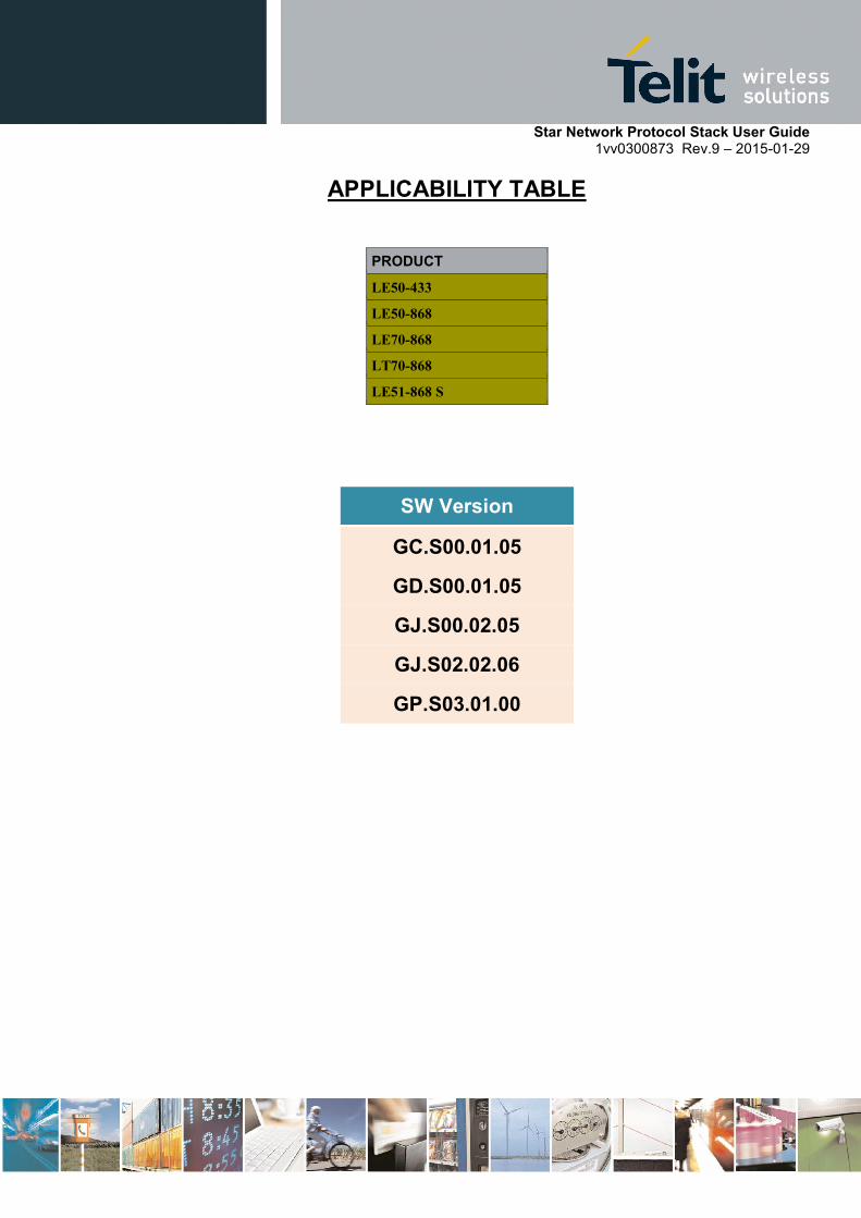
APPLICABILITY TABLE
PRODUCT
LE50-433
LE50-868
LE70-868
LT70-868
LE51-868 S
SW Version
GC.S00.01.05
GD.S00.01.05
GJ.S00.02.05
GJ.S02.02.06
GP.S03.01.00

Star Network Protocol Stack User Guide 1vv0300873 Rev.9 – 2015-01-29
Reproduction forbidden without written authorization from Telit Communications S.p.A.- All Rights Reserved. Page 3 of 66
SPECIFICATIONS SUBJECT TO CHANGE WITHOUT NOTICE
Notice
While reasonable efforts have been made to assure the accuracy of this document, Telit assumes no liability resulting from any inaccuracies or omissions in this document, or from use of the information obtained herein. The information in this document has been carefully checked and is believed to be entirely reliable. However, no responsibility is assumed for inaccuracies or omissions. Telit reserves the right to make changes to any products described herein and reserves the right to revise this document and to make changes from time to time in content hereof with no obligation to notify any person of revisions or changes. Telit does not assume any liability arising out of the application or use of any product, software, or circuit described herein; neither does it convey license under its patent rights or the rights of others.
It is possible that this publication may contain references to, or information about Telit products (machines and programs), programming, or services that are not announced in your country. Such references or information must not be construed to mean that Telit intends to announce such Telit products, programming, or services in your country.
Copyrights
This instruction manual and the Telit products described in this instruction manual may be, include or describe copyrighted Telit material, such as computer programs stored in semiconductor memories or other media. Laws in the Italy and other countries preserve for Telit and its licensors certain exclusive rights for copyrighted material, including the exclusive right to copy, reproduce in any form, distribute and make derivative works of the copyrighted material. Accordingly, any copyrighted material of Telit and its licensors contained herein or in the Telit products described in this instruction manual may not be copied, reproduced, distributed, merged or modified in any manner without the express written permission of Telit. Furthermore, the purchase of Telit products shall not be deemed to grant either directly or by implication, estoppel, or otherwise, any license under the copyrights, patents or patent applications of Telit, as arises by operation of law in the sale of a product.
Computer Software Copyrights
The Telit and 3rd Party supplied Software (SW) products described in this instruction manual may include copyrighted Telit and other 3rd Party supplied computer programs stored in semiconductor memories or other media. Laws in the Italy and other countries preserve for Telit and other 3rd Party supplied SW certain exclusive rights for copyrighted computer programs, including the exclusive right to copy or reproduce in any form the copyrighted computer program. Accordingly, any copyrighted Telit or other 3rd Party supplied SW computer programs contained in the Telit products described in this instruction manual may not be copied (reverse engineered) or reproduced in any manner without the express written permission of Telit or the 3rd Party SW supplier. Furthermore, the purchase of Telit products shall not be deemed to grant either directly or by implication, estoppel, or otherwise, any license under the copyrights, patents or patent applications of Telit or other 3rd Party supplied SW, except for the normal non-exclusive, royalty free license to use that arises by operation of law in the sale of a product.
Star Network Protocol Stack User Guide 1vv0300873 Rev.9 – 2015-01-29
Reproduction forbidden without written authorization from Telit Communications S.p.A.- All Rights Reserved. Page 4 of 66
Usage and Disclosure Restrictions
License Agreements
The software described in this document is the property of Telit and its licensors. It is furnished by express license agreement only and may be used only in accordance with the terms of such an agreement.
Copyrighted Materials
Software and documentation are copyrighted materials. Making unauthorized copies is prohibited by law. No part of the software or documentation may be reproduced, transmitted, transcribed, stored in a retrieval system, or translated into any language or computer language, in any form or by any means, without prior written permission of Telit
High Risk Materials
Components, units, or third-party products used in the product described herein are NOT fault-tolerant and are NOT designed, manufactured, or intended for use as on-line control equipment in the following hazardous environments requiring fail-safe controls: the operation of Nuclear Facilities, Aircraft Navigation or Aircraft Communication Systems, Air Traffic Control, Life Support, or Weapons Systems (High Risk Activities"). Telit and its supplier(s) specifically disclaim any expressed or implied warranty of fitness for such High Risk Activities.
Trademarks
TELIT and the Stylized T Logo are registered in Trademark Office. All other product or service names are the property of their respective owners.
Copyright © Telit Communications S.p.A. 2011 - 2015.
Star Network Protocol Stack User Guide 1vv0300873 Rev.9 – 2015-01-29
Reproduction forbidden without written authorization from Telit Communications S.p.A.- All Rights Reserved. Page 5 of 66
CONTENTS
1. Introduction ................................................................................................................... 7
1.1. Scope ....................................................................................................................... 7
1.2. Audience .................................................................................................................. 7
1.3. Contact Information, Support ................................................................................... 7
1.4. Document Organization ........................................................................................... 7
1.5. Text Conventions ..................................................................................................... 8
1.6. Related Documents .................................................................................................. 8
2. Description of Standard Functionalities ..................................................................... 9
2.1. Configuration mode .................................................................................................. 9
2.2. Operating mode ..................................................................................................... 12
2.2.1. Basic Illustration of Transparent mode ....................................................................... 13
2.2.2. Basic Illustration of Addressed Secured mode ........................................................... 13
2.2.3. Basic Illustration of Addressed Secured mode with LBT ............................................ 14
2.3. Public Registers Detailed Use ................................................................................ 15
2.3.1. Radio Configuration ................................................................................................... 15
2.3.2. Serial Link Configuration ............................................................................................ 20
2.3.3. Operating Mode configuration .................................................................................... 23
2.3.4. Network Configuration ............................................................................................... 24
2.3.5. Low Power Configuration ........................................................................................... 26
2.3.6. Smart Repeater Configuration (only for LE70-868) .................................................... 29
2.4. Public Registers List ............................................................................................... 31
2.5. Dedicated IO description. ....................................................................................... 39
2.5.1. TX LED (IO1) ............................................................................................................. 39
2.5.2. RX LED (IO2) ............................................................................................................. 39
2.5.3. ACK TX (IO8) ............................................................................................................. 39
2.5.4. Status RX/TX (IO9) .................................................................................................... 39
2.6. Hayes over the air .................................................................................................. 40
2.6.1. Requirements ............................................................................................................ 40
2.6.2. How to start Hayes over the air .................................................................................. 40
2.6.3. Particular case ........................................................................................................... 41
3. Description of Telemetry Functionalities ................................................................. 42
3.1. General Features ................................................................................................... 42
Star Network Protocol Stack User Guide 1vv0300873 Rev.9 – 2015-01-29
Reproduction forbidden without written authorization from Telit Communications S.p.A.- All Rights Reserved. Page 6 of 66
3.2. Telemetry Frames Description ............................................................................... 44
3.2.1. General Syntax .......................................................................................................... 45
3.2.2. Detailed description of Telemetry orders .................................................................... 46
3.2.3. Interruptible Inputs ..................................................................................................... 48
3.2.4. Telemetry Client ......................................................................................................... 48
3.3. IO Copy .................................................................................................................. 48
3.3.1. General Usage ........................................................................................................... 48
3.3.2. Optimized Usage ....................................................................................................... 52
3.4. Bindings ................................................................................................................. 54
4. Smart Repeater ........................................................................................................... 55
4.1. Description of Smart Repeater Functionalities ....................................................... 57
4.1.1. Data Communication example ................................................................................... 58
4.1.2. Telemetry Communication example ........................................................................... 59
4.1.3. Hayes Communication example ................................................................................ 60
4.2. Acknowledgments .................................................................................................. 61
5. LT70 ............................................................................................................................. 62
6. LE51-868 S .................................................................................................................. 63
7. Document History ....................................................................................................... 64
Star Network Protocol Stack User Guide 1vv0300873 Rev.9 – 2015-01-29
Reproduction forbidden without written authorization from Telit Communications S.p.A.- All Rights Reserved. Page 7 of 66
1. Introduction
1.1. Scope The scope of the document is to present the features and the application of the Star Network embedded stack available on Telit modules LE50-433, LE50-868, LE51-868 S and LE70-868.
1.2. Audience This document is intended for Telit customers, who are integrators, about to implement their applications using Telit radio modules.
1.3. Contact Information, Support For general contact, technical support, to report documentation errors and to order manuals, contact Telit Technical Support Center (TTSC) at:
[email protected] [email protected]
[email protected] [email protected]
Alternatively, use:
http://www.telit.com/en/products/technical-support-center/contact.php
For detailed information about where you can buy the Telit modules or for recommendations on accessories and components visit:
http://www.telit.com
To register for product news and announcements or for product questions contact Telit Technical Support Center (TTSC).
Our aim is to make this guide as helpful as possible. Keep us informed of your comments and suggestions for improvements.
Telit appreciates feedback from the users of our information.
1.4. Document Organization This document contains the following chapters:
Chapter 1: “Introduction” provides a scope for this document, target audience, contact and support information, and text conventions.
Star Network Protocol Stack User Guide 1vv0300873 Rev.9 – 2015-01-29
Reproduction forbidden without written authorization from Telit Communications S.p.A.- All Rights Reserved. Page 8 of 66
Chapter 2: “Description of Standard Functionalities” gives a detailed description of the standard functionalities and operation of the Star Network protocol stack.
Chapter 3: “Description of Telemetry Functionalities” gives a description of telemetry functionalities and operation of the Star Network protocol stack.
Chapter 4: “Smart Repeater” describes the Smart Repeater functionalities and gives some usage examples.
1.5. Text Conventions
Danger – This information MUST be followed or catastrophic equipment failure or bodily injury may occur.
Caution or Warning – Alerts the user to important points about integrating the module, if these points are not followed, the module and end user equipment may fail or malfunction.
Tip or Information – Provides advice and suggestions that may be useful when integrating the module.
All dates are in ISO 8601 format, i.e. YYYY-MM-DD.
1.6. Related Documents
[1] EN 300 220-2 v2.3.1 ETSI Standards for SRD , February 2010
[2] ERC Rec 70-03 ERC Recommendation for SRD, June 2010
[3] 2002/95/EC Directive of the European Parliament and of the Council, 27 January 2003
[4] SR Manager Tool User Guide 1vv0300899
[5] xE50-868/433 RF Module User Guide 1vv0300905
[6] 2006/771/EC Harmonization of the radio spectrum for use by short-range devices
[7] 2009/381/EC Amending Decision 2006/771/EC on harmonization of the radio spectrum for use by short-range devices
[8] SIGFOX NETWORK & STAR NETWORK protocols user guide 1vv0301109
Star Network Protocol Stack User Guide 1vv0300873 Rev.9 – 2015-01-29
Reproduction forbidden without written authorization from Telit Communications S.p.A.- All Rights Reserved. Page 9 of 66
2. Description of Standard Functionalities
This Chapter is dedicated to the standard functionality of the Star Network protocol stack.
There are 2 different modes available for Star Network protocol stack that are described in the following paragraphs:
The Configuration Mode which allows to parameter the module. It is set through the use of Hayes commands sent on the serial link.
The Operating Mode which is the functional use for data transmission
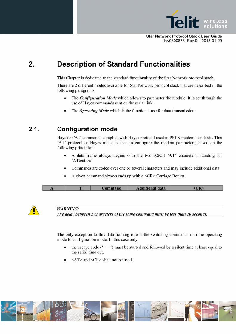
2.1. Configuration mode Hayes or 'AT' commands complies with Hayes protocol used in PSTN modem standards. This ‘AT’ protocol or Hayes mode is used to configure the modem parameters, based on the following principles:
A data frame always begins with the two ASCII ’AT’ characters, standing for ‘ATtention’
Commands are coded over one or several characters and may include additional data
A given command always ends up with a <CR> Carriage Return
A T Command Additional data <CR>
WARNING: The delay between 2 characters of the same command must be less than 10 seconds.
The only exception to this data-framing rule is the switching command from the operating mode to configuration mode. In this case only:
the escape code (‘+++’) must be started and followed by a silent time at least equal to the serial time out.
<AT> and <CR> shall not be used.
Star Network Protocol Stack User Guide 1vv0300873 Rev.9 – 2015-01-29
Reproduction forbidden without written authorization from Telit Communications S.p.A.- All Rights Reserved. Page 10 of 66
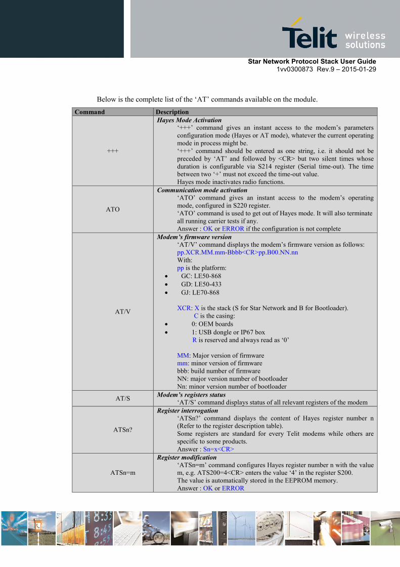
Below is the complete list of the ‘AT’ commands available on the module.
Command Description
+++
Hayes Mode Activation ‘+++’ command gives an instant access to the modem’s parameters configuration mode (Hayes or AT mode), whatever the current operating mode in process might be. ‘+++’ command should be entered as one string, i.e. it should not be preceded by ‘AT’ and followed by <CR> but two silent times whose duration is configurable via S214 register (Serial time-out). The time between two ‘+’ must not exceed the time-out value. Hayes mode inactivates radio functions.
ATO
Communication mode activation ‘ATO’ command gives an instant access to the modem’s operating mode, configured in S220 register. ‘ATO’ command is used to get out of Hayes mode. It will also terminate all running carrier tests if any. Answer : OK or ERROR if the configuration is not complete
AT/V
Modem’s firmware version ‘AT/V’ command displays the modem’s firmware version as follows: pp.XCR.MM.mm-Bbbb<CR>pp.B00.NN.nn With: pp is the platform:
GC: LE50-868 GD: LE50-433 GJ: LE70-868
XCR: X is the stack (S for Star Network and B for Bootloader). C is the casing:
0: OEM boards 1: USB dongle or IP67 box
R is reserved and always read as ‘0’ MM: Major version of firmware mm: minor version of firmware bbb: build number of firmware NN: major version number of bootloader Nn: minor version number of bootloader
AT/S Modem’s registers status
‘AT/S’ command displays status of all relevant registers of the modem
ATSn?
Register interrogation ‘ATSn?’ command displays the content of Hayes register number n (Refer to the register description table). Some registers are standard for every Telit modems while others are specific to some products. Answer : Sn=x<CR>
ATSn=m
Register modification ‘ATSn=m’ command configures Hayes register number n with the value m, e.g. ATS200=4<CR> enters the value ‘4’ in the register S200. The value is automatically stored in the EEPROM memory. Answer : OK or ERROR
Star Network Protocol Stack User Guide 1vv0300873 Rev.9 – 2015-01-29
Reproduction forbidden without written authorization from Telit Communications S.p.A.- All Rights Reserved. Page 11 of 66
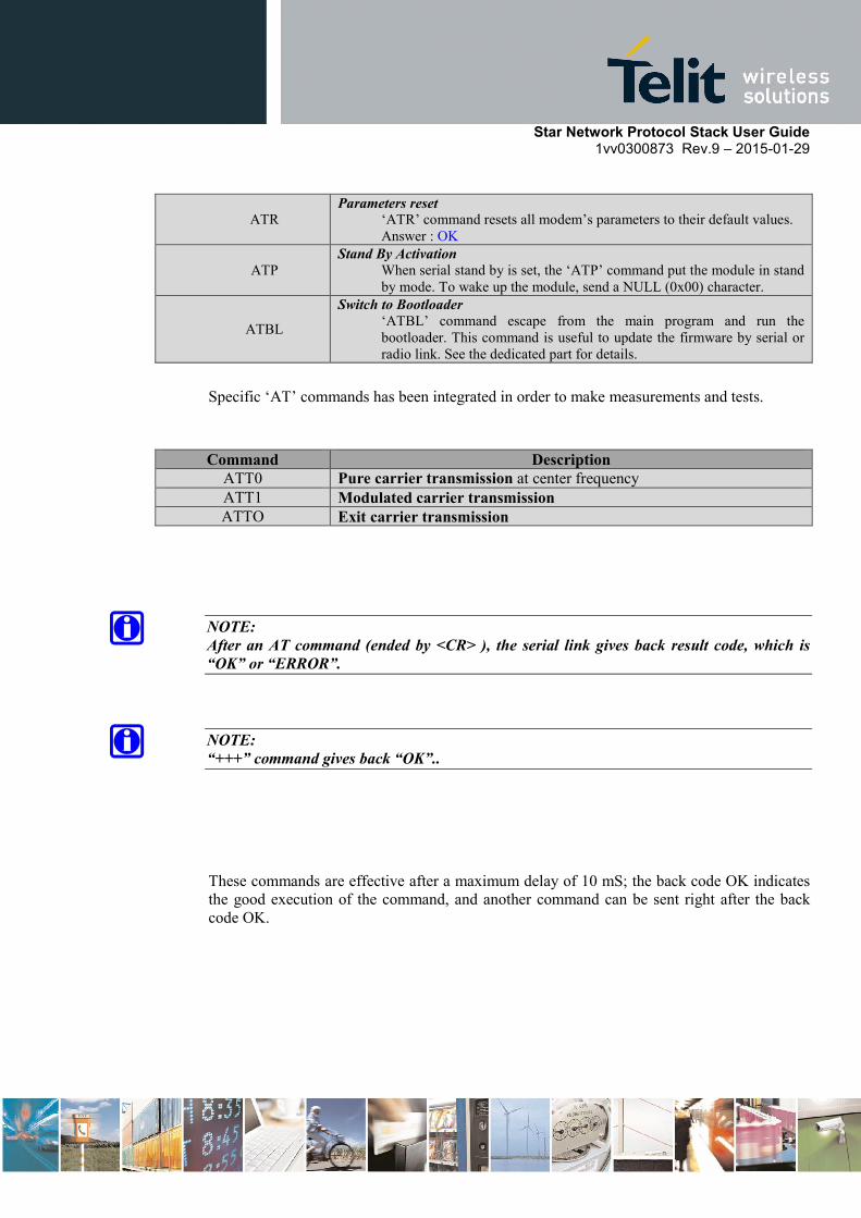
ATR Parameters reset
‘ATR’ command resets all modem’s parameters to their default values. Answer : OK
ATP Stand By Activation
When serial stand by is set, the ‘ATP’ command put the module in stand by mode. To wake up the module, send a NULL (0x00) character.
ATBL
Switch to Bootloader ‘ATBL’ command escape from the main program and run the bootloader. This command is useful to update the firmware by serial or radio link. See the dedicated part for details.
Specific ‘AT’ commands has been integrated in order to make measurements and tests.
Command Description
ATT0 Pure carrier transmission at center frequency ATT1 Modulated carrier transmission ATTO Exit carrier transmission
NOTE: After an AT command (ended by <CR> ), the serial link gives back result code, which is “OK” or “ERROR”.
NOTE: “+++” command gives back “OK”..
These commands are effective after a maximum delay of 10 mS; the back code OK indicates the good execution of the command, and another command can be sent right after the back code OK.
Star Network Protocol Stack User Guide 1vv0300873 Rev.9 – 2015-01-29
Reproduction forbidden without written authorization from Telit Communications S.p.A.- All Rights Reserved. Page 12 of 66
2.2. Operating mode There are 3 communication protocols available on the module:
Transparent mode: this is the default communication protocol of the module. The module transmits the data transparently, without encapsulation or addressing. It acts as a half duplex wired serial link (type RS485).
NOTE: Transparent mode allows sending big data frames and also streaming when radio baud rate is equal or greater than serial one.
Addressed Secured mode: it is a kind of multipoint network protocol. Each module can communicate with every other module in the same network. All the frames are addressed, checked through a CRC and acknowledged. This mode also allows sending telemetry commands over the network to monitor inputs or change output state of a remote identified module. Finally, this mode allows broadcasting by sending to address 0.
WARNING: Addressed Secured mode doesn’t allow sending big data frames. The whole serial frame needs to be stored in buffer before being treated and finally sent on the air. For this reason the maximum allowed size is 240 bytes.
Smart Repeater mode (only for LE70-868): extends the functionalities of Addressed
Secured mode by providing multi-hop communication between a coordinator and end nodes. It allows the exchange of data and telemetry packets between the coordinator and its nodes. It enables to control IOs of any remote node from coordinator by sending telemetry commands and to detect input events occurring on a node.
NOTE: Smart Repeater mode allows the most common network configurations (star, line distribution or a combination of the two types). Each network can be arranged in main branches (starting from coordinator) and in sub-branches (starting from a node other than coordinator).
In addition to these three modes, a few optional functionalities can be enabled like LBT, Wake on Radio, or AES encryption:
LBT (Listen Before Talk): It means that the transmitting module will scan the radio link and verify it is free (no radio activity) before sending its data to avoid collision. LBT is available in both transparent and Addressed Secured modes. See register S226 for details.
Wake on Radio: A device running Wake on Radio sleeps most of the time and periodically wakes up during a few milliseconds to listen to the radio channel. If an
Star Network Protocol Stack User Guide 1vv0300873 Rev.9 – 2015-01-29
Reproduction forbidden without written authorization from Telit Communications S.p.A.- All Rights Reserved. Page 13 of 66
incoming radio frame is detected, the module wakes up completely and performs the message treatment. Otherwise, the module returns immediately to stand by until next radio scan. This option allows sending radio messages to a sleeping module. Wake on Radio is available in both transparent and Addressed Secured modes. See registers S240, S243, S245 and S247 for details.
AES Encryption: When enabled, this option performs an AES 128 bits encryption of data sent in Addressed Secured mode. The encryption key is customizable. AES Encryption is only available in Addressed Secured mode and has no effect in Transparent mode. Only the user data are encrypted allowing to mix encrypted and clear messages in the same network. See registers S255 and S280 for details.
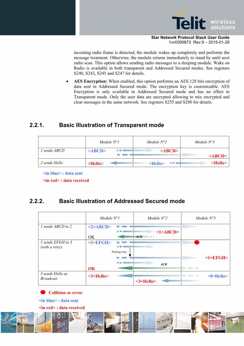
2.2.1. Basic Illustration of Transparent mode
Module N°1 Module N°2 Module N°3
1 sends ABCD <ABCD> <ABCD> <ABCD>
2 sends Hello <Hello> <Hello> <Hello>
2.2.2. Basic Illustration of Addressed Secured mode
Module N°1 Module N°2 Module N°3
1 sends ABCD to 2 <2=ABCD>
OK
<1=ABCD>
1 sends EFGH to 3 (with a retry)
<3=EFGH>
OK
<1=EFGH>
3 sends Hello as Broadcast
<3=Hello> <3=Hello>
<0=Hello>
Waiting time
ACK
ACK
<in blue> : data sent
<in red> : data received
Collision or error
<in blue> : data sent
<in red> : data received
Star Network Protocol Stack User Guide 1vv0300873 Rev.9 – 2015-01-29
Reproduction forbidden without written authorization from Telit Communications S.p.A.- All Rights Reserved. Page 14 of 66
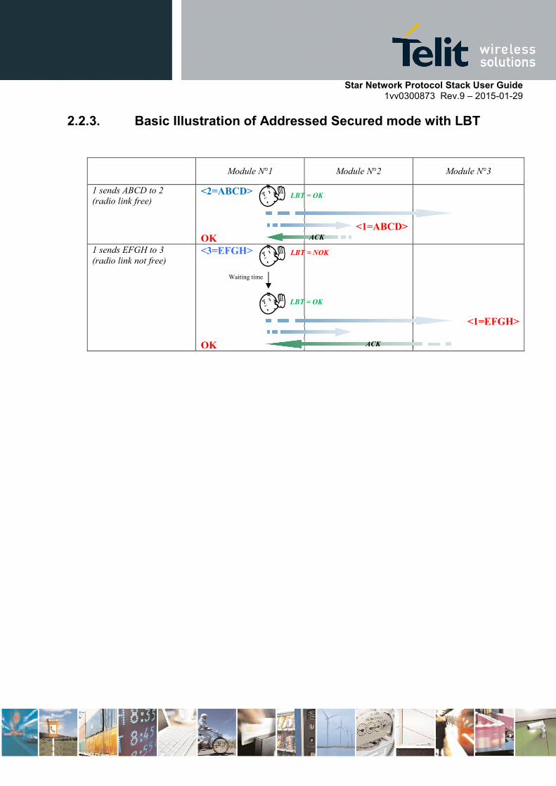
2.2.3. Basic Illustration of Addressed Secured mode with LBT
Module N°1 Module N°2 Module N°3
1 sends ABCD to 2 (radio link free)
<2=ABCD>
OK
<1=ABCD>
1 sends EFGH to 3 (radio link not free)
<3=EFGH>
OK
<1=EFGH>
Waiting time
ACK
ACK
LBT = OK
LBT = NOK
LBT = OK
Star Network Protocol Stack User Guide 1vv0300873 Rev.9 – 2015-01-29
Reproduction forbidden without written authorization from Telit Communications S.p.A.- All Rights Reserved. Page 15 of 66
2.3. Public Registers Detailed Use The configurable parameters via Hayes mode are stored in the module permanent memory, called S registers. Those registers are always listed as follow:
S20x registers correspond to the radio parameters
S21x registers correspond to the serial parameters
S22x registers correspond to the operating parameters
S24x registers correspond to low power parameters
S25x registers correspond to the network parameters
S26x registers correspond to the telemetry parameters
2.3.1. Radio Configuration
The Radio configuration is set via the S20x registers. Through them, you can:
Change radio channel : S200
Change the radio baud rate : S201
Change the radio Output Power : S202
Modify the carrier length : S204
Change Radio Frequency Sub-Band : S206
Configure the syncword in transmission and reception: S207
Change Xor pattern applied on radio data: S209
The radio parameters are preferably set in the following order:
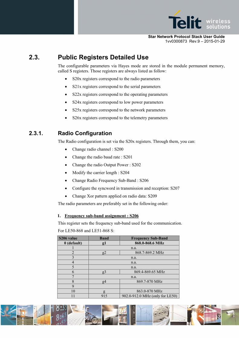
1. Frequency sub-band assignment : S206
This register sets the frequency sub-band used for the communication.
For LE50-868 and LE51-868 S:
S206 value Band Frequency Sub-Band 0 (default) g1 868.0-868.6 MHz
1 n.a. 2 g2 868.7-869.2 MHz 3 n.a. 4 n.a. 5 n.a. 6 g3 869.4-869.65 MHz 7 n.a. 8 g4 869.7-870 MHz 9 10 g 863.0-870 MHz 11 915 902.0-912.0 MHz (only for LE50)
Star Network Protocol Stack User Guide 1vv0300873 Rev.9 – 2015-01-29
Reproduction forbidden without written authorization from Telit Communications S.p.A.- All Rights Reserved. Page 16 of 66
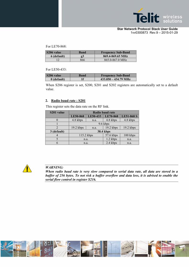
For LE70-868:
S206 value Band Frequency Sub-Band 6 (default) g3 869.4-869.65 MHz
12 866 865.0-867.0 MHz
For LE50-433:
S206 value Band Frequency Sub-Band 0 (default) 1f 433.050 – 434.79 MHz
When S206 register is set, S200, S201 and S202 registers are automatically set to a default value.
2. Radio baud rate : S201
This register sets the data rate on the RF link.
S201 value Radio baud rate LE50-868 LE50-433 LE70-868 LE51-868 S
0 4.8 kbps n.a. 4.8 kbps 4.8 kbps 1 9.6 kbps 2 19.2 kbps n.a. 19.2 kbps 19.2 kbps
3 (default) 38.4 kbps 4 115.2 kbps 57.6 kbps 100 kbps 5 n.a. 1.2 kbps n.a. 6 n.a. 2.4 kbps n.a.
WARNING: When radio baud rate is very slow compared to serial data rate, all data are stored in a buffer of 256 bytes. To not risk a buffer overflow and data loss, it is advised to enable the serial flow control in register S216.
Star Network Protocol Stack User Guide 1vv0300873 Rev.9 – 2015-01-29
Reproduction forbidden without written authorization from Telit Communications S.p.A.- All Rights Reserved. Page 17 of 66
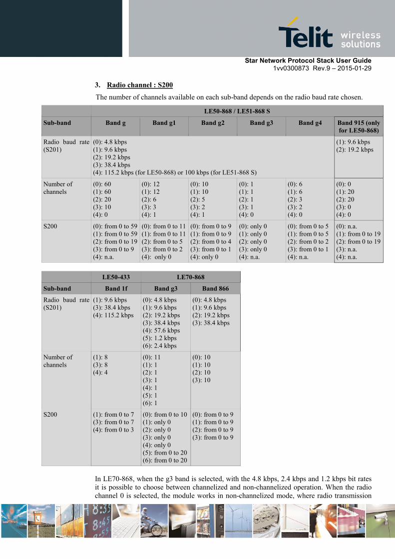
3. Radio channel : S200
The number of channels available on each sub-band depends on the radio baud rate chosen.
LE50-868 / LE51-868 S
Sub-band Band g Band g1 Band g2 Band g3 Band g4 Band 915 (only for LE50-868)
Radio baud rate (S201)
(0): 4.8 kbps (1): 9.6 kbps (2): 19.2 kbps (3): 38.4 kbps (4): 115.2 kbps (for LE50-868) or 100 kbps (for LE51-868 S)
(1): 9.6 kbps (2): 19.2 kbps
Number of channels
(0): 60 (1): 60 (2): 20 (3): 10 (4): 0
(0): 12 (1): 12 (2): 6 (3): 3 (4): 1
(0): 10 (1): 10 (2): 5 (3): 2 (4): 1
(0): 1 (1): 1 (2): 1 (3): 1 (4): 0
(0): 6 (1): 6 (2): 3 (3): 2 (4): 0
(0): 0 (1): 20 (2): 20 (3): 0 (4): 0
S200 (0): from 0 to 59 (1): from 0 to 59 (2): from 0 to 19 (3): from 0 to 9 (4): n.a.
(0): from 0 to 11 (1): from 0 to 11 (2): from 0 to 5 (3): from 0 to 2 (4): only 0
(0): from 0 to 9 (1): from 0 to 9 (2): from 0 to 4 (3): from 0 to 1 (4): only 0
(0): only 0 (1): only 0 (2): only 0 (3): only 0 (4): n.a.
(0): from 0 to 5 (1): from 0 to 5 (2): from 0 to 2 (3): from 0 to 1 (4): n.a.
(0): n.a. (1): from 0 to 19 (2): from 0 to 19 (3): n.a. (4): n.a.
LE50-433 LE70-868
Sub-band Band 1f Band g3 Band 866
Radio baud rate (S201)
(1): 9.6 kbps (3): 38.4 kbps (4): 115.2 kbps
(0): 4.8 kbps (1): 9.6 kbps (2): 19.2 kbps (3): 38.4 kbps (4): 57.6 kbps (5): 1.2 kbps (6): 2.4 kbps
(0): 4.8 kbps (1): 9.6 kbps (2): 19.2 kbps (3): 38.4 kbps
Number of channels
(1): 8 (3): 8 (4): 4
(0): 11 (1): 1 (2): 1 (3): 1 (4): 1 (5): 1 (6): 1
(0): 10 (1): 10 (2): 10 (3): 10
S200 (1): from 0 to 7 (3): from 0 to 7 (4): from 0 to 3
(0): from 0 to 10 (1): only 0 (2): only 0 (3): only 0 (4): only 0 (5): from 0 to 20 (6): from 0 to 20
(0): from 0 to 9 (1): from 0 to 9 (2): from 0 to 9 (3): from 0 to 9
In LE70-868, when the g3 band is selected, with the 4.8 kbps, 2.4 kbps and 1.2 kbps bit rates it is possible to choose between channelized and non-channelized operation. When the radio channel 0 is selected, the module works in non-channelized mode, where radio transmission
Star Network Protocol Stack User Guide 1vv0300873 Rev.9 – 2015-01-29
Reproduction forbidden without written authorization from Telit Communications S.p.A.- All Rights Reserved. Page 18 of 66
uses as carrier the center frequency of the g3 band. At 4.8 kbps, channel numbers from 1 to 10 use channelized mode, in which the available bandwidth is split in 10 channels of 25 kHz each. At 2.4 kbps and 1.2 kbps, channel numbers from 1 to 20 use channelized mode, in which the available bandwidth is split in 20 channels of 12.5 kHz each. In every channelized mode, the maximum output power is limited to 23 dBm. In addition, LE70-868 supports operation in the 866 MHz frequency band, selected by the value 12 in register S206. In this band 10 channels are allocated, covering frequencies from 865 to 867 MHz.
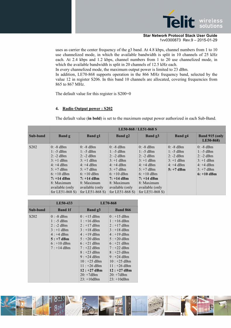
The default value for this register is S200=0 4. Radio Output power : S202
The default value (in bold) is set to the maximum output power authorized in each Sub-Band.
LE50-868 / LE51-868 S
Sub-band Band g Band g1 Band g2 Band g3 Band g4 Band 915 (only LE50-868)
S202 0: -8 dBm 1: -5 dBm 2: -2 dBm 3: +1 dBm 4: +4 dBm 5: +7 dBm 6: +10 dBm 7: +14 dBm 8: Maximum available (only for LE51-868 S)
0: -8 dBm 1: -5 dBm 2: -2 dBm 3: +1 dBm 4: +4 dBm 5: +7 dBm 6: +10 dBm 7: +14 dBm 8: Maximum available (only for LE51-868 S)
0: -8 dBm 1: -5 dBm 2: -2 dBm 3: +1 dBm 4: +4 dBm 5: +7 dBm 6: +10 dBm 7: +14 dBm 8: Maximum available (only for LE51-868 S)
0: -8 dBm 1: -5 dBm 2: -2 dBm 3: +1 dBm 4: +4 dBm 5: +7 dBm 6: +10 dBm 7: +14 dBm 8: Maximum available (only for LE51-868 S)
0: -8 dBm 1: -5 dBm 2: -2 dBm 3: +1 dBm 4: +4 dBm 5: +7 dBm
0: -8 dBm 1: -5 dBm 2: -2 dBm 3: +1 dBm 4: +4 dBm 5: +7 dBm 6: +10 dBm
LE50-433 LE70-868
Sub-band Band 1f Band g3 Band 866
S202 0 : -8 dBm 1 : -5 dBm 2 : -2 dBm 3 : +1 dBm 4 : +4 dBm 5 : +7 dBm 6 : +10 dBm 7 : +14 dBm
0 : +15 dBm 1 : +16 dBm 2 : +17 dBm 3 : +18 dBm 4 : +19 dBm 5 : +20 dBm 6 : +21 dBm 7 : +22 dBm 8 : +23 dBm 9 : +24 dBm 10 : +25 dBm 11 : +26 dBm 12 : +27 dBm 20: +7dBm 23: +10dBm
0 : +15 dBm 1 : +16 dBm 2 : +17 dBm 3 : +18 dBm 4 : +19 dBm 5 : +20 dBm 6 : +21 dBm 7 : +22 dBm 8 : +23 dBm 9 : +24 dBm 10 : +25 dBm 11 : +26 dBm 12 : +27 dBm 20: +7dBm 23: +10dBm
Star Network Protocol Stack User Guide 1vv0300873 Rev.9 – 2015-01-29
Reproduction forbidden without written authorization from Telit Communications S.p.A.- All Rights Reserved. Page 19 of 66
In LE70-868, the maximum output power is 27 dBm, except when operating in the g3 band at 4800 bps in channelized mode: in this configuration the maximum allowed power is 23 dBm. 5. Radio preamble length : S204
This register sets the length (in bytes) of the radio preamble sent before the data. It serves as synchronization frame for the receiver(s). The default value is 8 bytes (S204=8).
If the radio receiver is configured in low power with wake on radio activated, then the preamble length of the sender may be increased to have more chance to be detected by the remote sleeping module. See Wake On Radio chapter for more details.
Without low power consideration, this register does not have to be modified. However, in some hostile environments (metallic parts, vibrations…) it can be increased to have a more reliable synchronization. This will lower the over air throughput as it increases the non-data use of the radio.
Acknowledge frames sent automatically by the module in addressed mode are always sent with the default preamble length, regardless of the value of register S204.
6. Syncword configuration : S207
This register provides the ability to select between different radio frame syncwords. The syncword used during transmission can be configured independently from the syncword in reception. In order for a module to be able to communicate with another module, the syncword used by a module for transmission must be the same as the syncword used by the other module for reception. This register allows to configure different modules so that communication is activated only between specific modules.
7. Radio Whitening Character : S209
This register sets the value XORed with each character of the radio frame in order to avoid long sequences of 0s or 1s. If the user application sends frames containing series of 0x00 or 0xFF, the receiver can unsynchronize itself, thus the need for this whitening.
To mix a frame of these types, use a value of 170 (Hex: 0xAA, Bin: 10101010).
Star Network Protocol Stack User Guide 1vv0300873 Rev.9 – 2015-01-29
Reproduction forbidden without written authorization from Telit Communications S.p.A.- All Rights Reserved. Page 20 of 66
2.3.2. Serial Link Configuration
The serial link configuration is set via the S21x registers. Through them, you can:
Set the serial baud rate : S210,
Set the parity : S212,
Set the number of stop bits: S213,
Set the serial time-out : S214,
Set the serial link type: S215 (only for LT70-868 Terminal),
Set the flow control type: S216.
After each modification in the serial settings, the module will answer ‘OK’ with the current configuration, and the changes will be effective immediately after.
The Serial parameters are preferably set in the following order:
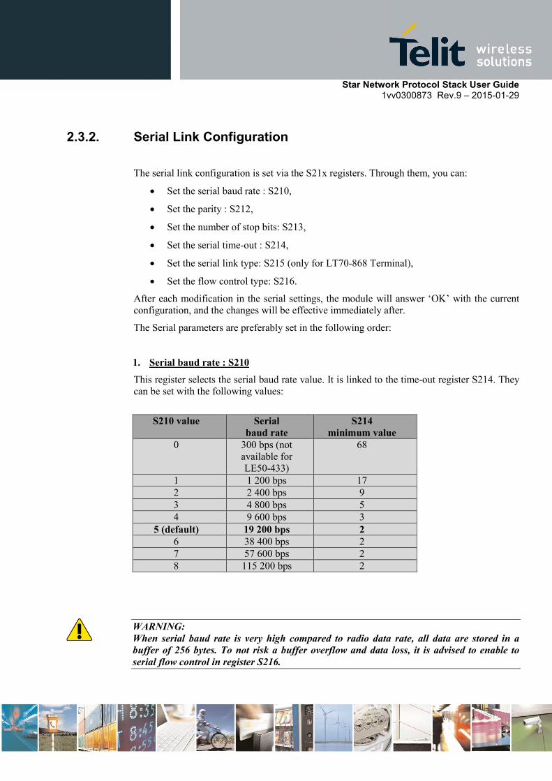
1. Serial baud rate : S210
This register selects the serial baud rate value. It is linked to the time-out register S214. They can be set with the following values:
S210 value Serial
baud rate S214
minimum value 0 300 bps (not
available for LE50-433)
68
1 1 200 bps 17 2 2 400 bps 9 3 4 800 bps 5 4 9 600 bps 3
5 (default) 19 200 bps 2 6 38 400 bps 2 7 57 600 bps 2 8 115 200 bps 2
WARNING: When serial baud rate is very high compared to radio data rate, all data are stored in a buffer of 256 bytes. To not risk a buffer overflow and data loss, it is advised to enable to serial flow control in register S216.
Star Network Protocol Stack User Guide 1vv0300873 Rev.9 – 2015-01-29
Reproduction forbidden without written authorization from Telit Communications S.p.A.- All Rights Reserved. Page 21 of 66
2. Serial data format : S211, S212 and S213
These registers set the format of the characters sent on the serial link:
S211: Number of data bits: the allowed values are 7 and 8. Default value is S211=8.
S212: Parity. It can take three values: '1' for No Parity, '2' for Even Parity, or '3' for Odd Parity. The default value is S212=1.
S213: Number of Stop bits: 1 bit or 2 bits. Default value is S213=1.
3. Serial timeout : S214
The module is not able to know when a frame reception is finished on the serial link, but it needs this information to stop radio transmission in transparent mode, or to start sending data in the other modes.
This timeout is the indicator used to decide when the data frame is finished: if no character is received for a time equal to this timeout, the data frame is seen as finished and the modem acts accordingly.
The default value is 5 milliseconds.
The timeout value is of course in accordance with the serial baud rate : it must be at least equal to the length of 2 characters. See the table in the baud rate (S210) part of this chapter. For example, for a 19200 bps baud rate, the time to send 1 character (1 start bit + 8 data bits + 1 stop bit) is 521 µs, giving a rounded up timeout value of 2 ms.
You can set a higher value to this timeout if you have some gaps in the sending of a frame.
4. Serial link type: S215 (only for LT70-868 Terminal)
The LE70-868 serial link can be configured to work in any of the 4 following modes:
RS232 (S215=0, default value): This is the standard full duplex serial link. It works on up to 5 signals (3 without flow control): RxD, TxD, RTS, CTS and GND, and uses +/-12V levels. It is the only serial link type allowing flow control.
RS422 (S215=1): Full duplex link on 4 wires using voltage difference.
RS485 (S215=2): Half duplex link on 2 wires using voltage difference.
RS485-Full (S215=3: Full duplex link on 4 wires using voltage difference. Unlike the point-to-point RS422 protocol, it can be used for multipoint operations.
WARNING: ATR command doesn’t reset this register to its default value.
Star Network Protocol Stack User Guide 1vv0300873 Rev.9 – 2015-01-29
Reproduction forbidden without written authorization from Telit Communications S.p.A.- All Rights Reserved. Page 22 of 66
5. Flow control management : S216
In all the modes, the data coming from the serial link are stored in a buffer and then sent. Thus, for long frame greater than 240 bytes it is necessary to have a flow control on the serial link to avoid a buffer overflow and the loss of data. If long frames are sent without flow control, some data may be lost. In transparent mode, if serial data rate is equal to radio one, the flow control can be disabled because in this case the buffer does not risk overflow.
The module manages three types of flow control:
Hardware or CTS/RTS (S216=0): the RTS signal from the module will authorize the host to transmit data.
Software or Xon/Xoff (S216=1): the module sends a Xoff character on the serial link to interrupt the transmission from the host, and a Xon character to resume. This control will only work from the module to the host.
None (S216=2, default): the host must manage its outgoing data frames in order not to overflow the buffer.
This flow control is available for our virtual RS232 serial link.
NOTE: In Hayes mode, the flow control is not active so as to be able to modify these registers without locking the serial link.
Star Network Protocol Stack User Guide 1vv0300873 Rev.9 – 2015-01-29
Reproduction forbidden without written authorization from Telit Communications S.p.A.- All Rights Reserved. Page 23 of 66
2.3.3. Operating Mode configuration
The Operating mode configuration is set via the S22x registers. Through them, you can:
Set the operating mode : S220,
Set the number of retries: S223,
Set the LBT: S226
Set the random waiting time : S227
Set Hayes over the air: S228
The Operating Mode parameters are preferably set in the following order:
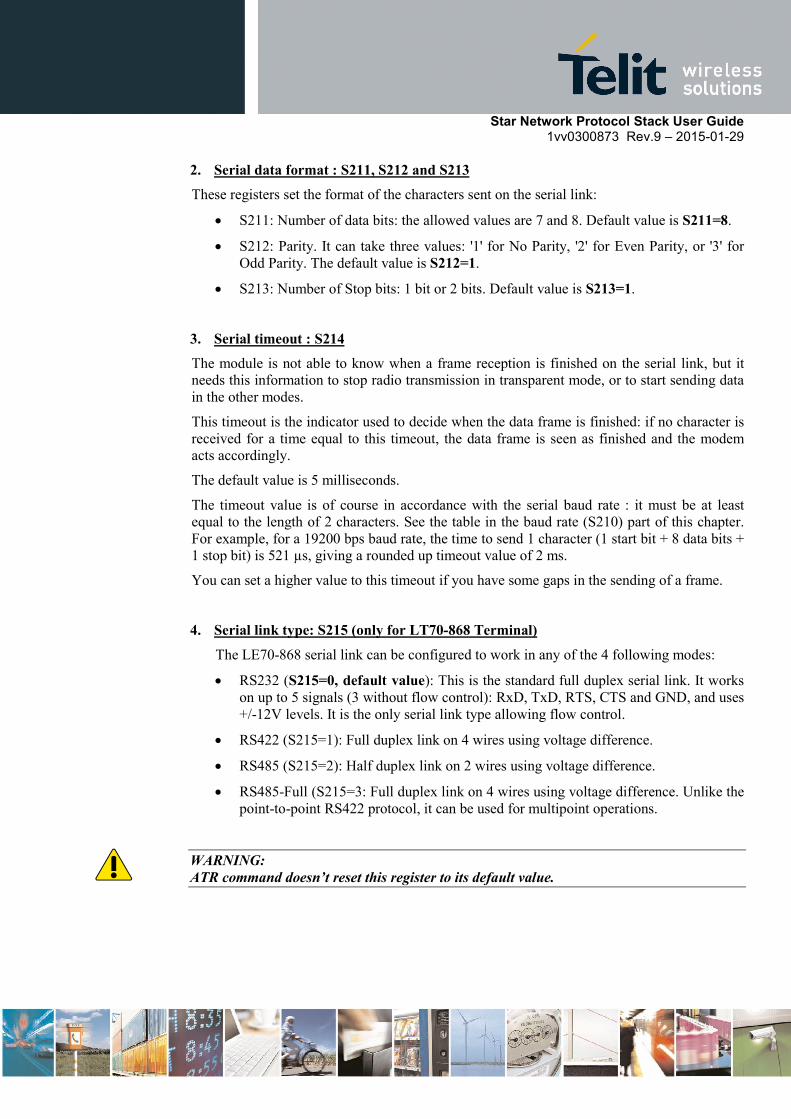
Operating Mode : S220
This is the most significant register: it tells how the module must run. The available operating modes are:
Value Mode 1 Transparent Mode (default) 9 Addressed Secured Mode 10 Smart Repeater Coordinator (only for LE70-868 and
LE51-868 S) 11 Smart Repeater Node (only for LE70-868 and LE51-
868 S)
LBT : S226
This register allows activating and setting up the LBT functionality. The LBT sensitivity refers to the detected RF level over which the RF link is considered as occupied.
Value LBT Comment 0 OFF (default) no LBT 1 ON with high sensitivity LBT with detection for RF >-90dBm 2 ON with medium sensitivity LBT with detection for RF >-80dBm 3 ON with low sensitivity LBT with detection for RF >-70dBm
Number of repetitions : S223
This register is used in Addressed Secured mode. It is the number of times the message will be repeated in case of non acknowledgement, or the number of times the module will try to send the message in case of the radio link is not free (when LBT functionality is activated).
This register is set to 2 as default. It is enough in most of the configurations.
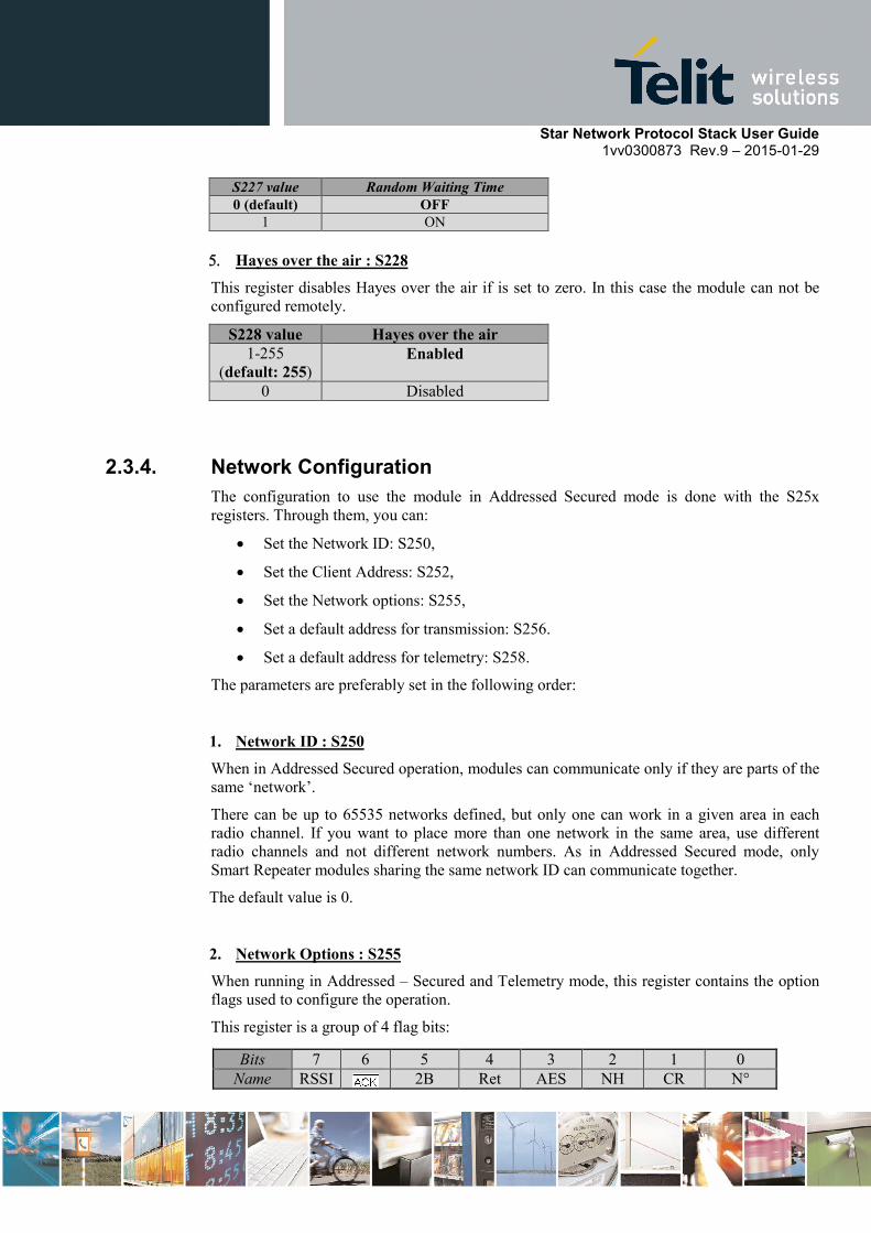
Random waiting time : S227
This register activates a random waiting time before every radio transmission (except for acknowledge). The random waiting time is comprised between 0 and 64mS.
Star Network Protocol Stack User Guide 1vv0300873 Rev.9 – 2015-01-29
Reproduction forbidden without written authorization from Telit Communications S.p.A.- All Rights Reserved. Page 24 of 66
S227 value Random Waiting Time 0 (default) OFF
1 ON
Hayes over the air : S228
This register disables Hayes over the air if is set to zero. In this case the module can not be configured remotely.
S228 value Hayes over the air 1-255
(default: 255) Enabled
0 Disabled
2.3.4. Network Configuration
The configuration to use the module in Addressed Secured mode is done with the S25x registers. Through them, you can:
Set the Network ID: S250,
Set the Client Address: S252,
Set the Network options: S255,
Set a default address for transmission: S256.
Set a default address for telemetry: S258.
The parameters are preferably set in the following order:
1. Network ID : S250
When in Addressed Secured operation, modules can communicate only if they are parts of the same ‘network’.
There can be up to 65535 networks defined, but only one can work in a given area in each radio channel. If you want to place more than one network in the same area, use different radio channels and not different network numbers. As in Addressed Secured mode, only Smart Repeater modules sharing the same network ID can communicate together.
The default value is 0.
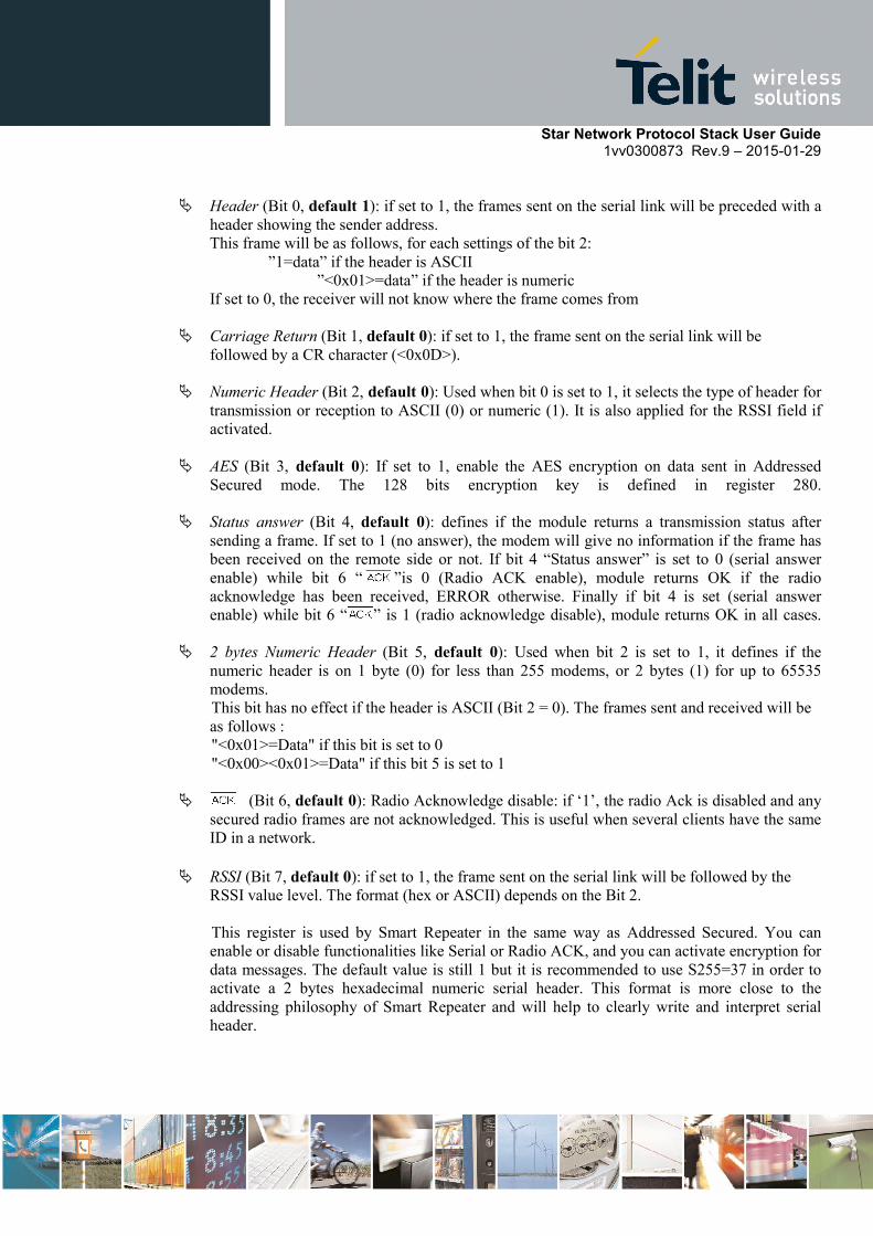
2. Network Options : S255
When running in Addressed – Secured and Telemetry mode, this register contains the option flags used to configure the operation.
This register is a group of 4 flag bits:
Bits 7 6 5 4 3 2 1 0 Name RSSI 2B Ret AES NH CR N°
Star Network Protocol Stack User Guide 1vv0300873 Rev.9 – 2015-01-29
Reproduction forbidden without written authorization from Telit Communications S.p.A.- All Rights Reserved. Page 25 of 66
Header (Bit 0, default 1): if set to 1, the frames sent on the serial link will be preceded with a
header showing the sender address. This frame will be as follows, for each settings of the bit 2: ”1=data” if the header is ASCII ”<0x01>=data” if the header is numeric If set to 0, the receiver will not know where the frame comes from
Carriage Return (Bit 1, default 0): if set to 1, the frame sent on the serial link will be
followed by a CR character (<0x0D>).
Numeric Header (Bit 2, default 0): Used when bit 0 is set to 1, it selects the type of header for transmission or reception to ASCII (0) or numeric (1). It is also applied for the RSSI field if activated.
AES (Bit 3, default 0): If set to 1, enable the AES encryption on data sent in Addressed Secured mode. The 128 bits encryption key is defined in register 280.
Status answer (Bit 4, default 0): defines if the module returns a transmission status after sending a frame. If set to 1 (no answer), the modem will give no information if the frame has been received on the remote side or not. If bit 4 “Status answer” is set to 0 (serial answer enable) while bit 6 “ ”is 0 (Radio ACK enable), module returns OK if the radio acknowledge has been received, ERROR otherwise. Finally if bit 4 is set (serial answer enable) while bit 6 “ ” is 1 (radio acknowledge disable), module returns OK in all cases.
2 bytes Numeric Header (Bit 5, default 0): Used when bit 2 is set to 1, it defines if the numeric header is on 1 byte (0) for less than 255 modems, or 2 bytes (1) for up to 65535 modems. This bit has no effect if the header is ASCII (Bit 2 = 0). The frames sent and received will be as follows : "<0x01>=Data" if this bit is set to 0 "<0x00><0x01>=Data" if this bit 5 is set to 1
(Bit 6, default 0): Radio Acknowledge disable: if ‘1’, the radio Ack is disabled and any secured radio frames are not acknowledged. This is useful when several clients have the same ID in a network.
RSSI (Bit 7, default 0): if set to 1, the frame sent on the serial link will be followed by the
RSSI value level. The format (hex or ASCII) depends on the Bit 2.
This register is used by Smart Repeater in the same way as Addressed Secured. You can enable or disable functionalities like Serial or Radio ACK, and you can activate encryption for data messages. The default value is still 1 but it is recommended to use S255=37 in order to activate a 2 bytes hexadecimal numeric serial header. This format is more close to the addressing philosophy of Smart Repeater and will help to clearly write and interpret serial header.
Star Network Protocol Stack User Guide 1vv0300873 Rev.9 – 2015-01-29
Reproduction forbidden without written authorization from Telit Communications S.p.A.- All Rights Reserved. Page 26 of 66
3. Client Address: S252
The user can set a Client number between 1 and 65535. The client numbers must all be different in a network. It is not used by Smart Repeater; values entered in this register are ignored when the module is configured in Smart Repeater.
The default value is 1. Value 0 is not permitted because reserved for broadcast transmission.
4. Default transmission Address: S256
If this register is different from 0, the frames received on the serial link will be sent to this address, without any header detection done.
This register is useful to set a Network-like system with up to 65534 clients and one server, and/or when the clients are not able to manage the frame header.
It is not used by Smart Repeater; values entered in this register are ignored when the module is configured in Smart Repeater.
5. Default telemetry Address: S258
This register is used in telemetry functions to define a binding between 2 modules.
When the I/O copy function is enabled (see register 260) the inputs of the local module are copied on the output of the module specified in register S258.
This register is also used in edge detection and telemetry client operation to select the node to which frames containing the IO state of the local node are sent.
It is not used by Smart Repeater; values entered in this register are ignored when the module is configured in Smart Repeater.
2.3.5. Low Power Configuration
The configuration to use low power features is done with the S24x registers. Through them, you can:
Choose the stand by mode : S240,
Set the sleeping duration : S243
Set the RX awake duration: S245
Set the time out before returning to stand by: S247
WARNING: You should not use Low Power options when the module is in Smart Repeater mode.
Star Network Protocol Stack User Guide 1vv0300873 Rev.9 – 2015-01-29
Reproduction forbidden without written authorization from Telit Communications S.p.A.- All Rights Reserved. Page 27 of 66
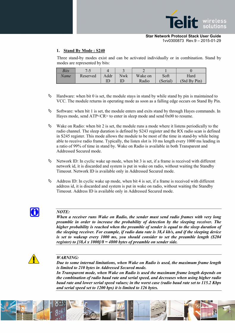
1. Stand By Mode : S240
Three stand-by modes exist and can be activated individually or in combination. Stand by modes are represented by bits:
Bits 7-5 4 3 2 1 0 Name Reserved Addr
ID Nwk
ID Wake on Radio
Soft (Serial)
Hard (Std By Pin)
Hardware: when bit 0 is set, the module stays in stand by while stand by pin is maintained to VCC. The module returns in operating mode as soon as a falling edge occurs on Stand By Pin.
Software: when bit 1 is set, the module enters and exits stand by through Hayes commands. In
Hayes mode, send ATP<CR> to enter in sleep mode and send 0x00 to resume.
Wake on Radio: when bit 2 is set, the module runs a mode where it listens periodically to the radio channel. The sleep duration is defined by S243 register and the RX radio scan is defined in S245 register. This mode allows the module to be most of the time in stand-by while being able to receive radio frame. Typically, the listen slot is 10 ms length every 1000 ms leading in a ratio of 99% of time in stand by. Wake on Radio is available in both Transparent and Addressed Secured mode.
Network ID: In cyclic wake up mode, when bit 3 is set, if a frame is received with different
network id, it is discarded and system is put in wake on radio, without waiting the Standby Timeout. Network ID is available only in Addressed Secured mode.
Address ID: In cyclic wake up mode, when bit 4 is set, if a frame is received with different
address id, it is discarded and system is put in wake on radio, without waiting the Standby Timeout. Address ID is available only in Addressed Secured mode.
NOTE: When a receiver runs Wake on Radio, the sender must send radio frames with very long preamble in order to increase the probability of detection by the sleeping receiver. The higher probability is reached when the preamble of sender is equal to the sleep duration of the sleeping receiver. For example, if radio data rate is 38,4 kb/s, and if the sleeping device is set to wakeup every 1000 ms, you should consider to set the preamble length (S204 register) to [38,4 x 1000]/8 = 4800 bytes of preamble on sender side.
WARNING: Due to some internal limitations, when Wake on Radio is used, the maximum frame length is limited to 210 bytes in Addressed Secured mode. In Transparent mode, when Wake on Radio is used the maximum frame length depends on the combination of radio baud rate and serial speed, and decreases when using higher radio baud rate and lower serial speed values; in the worst case (radio baud rate set to 115.2 Kbps and serial speed set to 1200 bps) it is limited to 126 bytes.
Star Network Protocol Stack User Guide 1vv0300873 Rev.9 – 2015-01-29
Reproduction forbidden without written authorization from Telit Communications S.p.A.- All Rights Reserved. Page 28 of 66
WARNING: Wake on Radio can not be enabled alone; otherwise there is a risk to never take back control of the sleeping module. Wake on Radio is enabled only in combination with Hard stand by mode ensuring to always have a chance to awake the module by stand-by pin.
WARNING: Network Id and Address Id must be enabled in combination of wake on radio.
The default value is 0, no stand by activated.
2. Sleep Duration : S243
The role of this register is double.
When Wake on Radio is activated (Register S240), the present register gives the sleep duration in milliseconds between two radio scans.
When Telemetry mode (Register S260) is set to either “IO copy Client” or “Telemetry Client”, the present register gives the IDLE duration between two IO Copy or Telemetry frames; in this case, value should be a multiple of 1000 ms.
If both Wake on Radio and IO copy or Telemetry Client are activated, this register gives the sleep duration between two IO Copy or Telemetry frames.
Default value is 1000 ms.
3. RX Duration : S245
When Wake on Radio is activated (Register S240), the present register gives the RX scan duration in milliseconds. Typically a few milliseconds are enough in order to save the maximum of energy; the minimum duration needed to detect a frame preamble increases with decreasing radio speed values.
Default value is 10 ms.
4. Time Out before returning to sleep : S247
When Wake on Radio is activated (Register S240), this register gives the timeout duration in milliseconds without any activity before returning to sleep. Thanks to this register it is possible to continue exchanging messages after having awaked a remote sleeping device. The module waits for this timeout before returning in stand-by. If an activity (serial or radio) occurs before timeout is elapsed, the timeout is re launched for a new S247 ms duration. This register is used when the received radio message, forwarded to serial, will trigger a serial response which can then be forwarded on radio immediately. When no response is envisaged,
Star Network Protocol Stack User Guide 1vv0300873 Rev.9 – 2015-01-29
Reproduction forbidden without written authorization from Telit Communications S.p.A.- All Rights Reserved. Page 29 of 66
it is not needed to loss time and energy, in such situation, this register can be reduced to only a few milliseconds.
Default value is 100 ms.
2.3.6. Smart Repeater Configuration (only for LE70-868)
Some registers are used to configure the Smart Repeater mode (refer to Section 4 for a description of this functionality). These registers have been sorted in two parts: S27X are registers only used by Smart Repeater nodes, while S3XX are the registers used by Smart Repeater coordinator only.
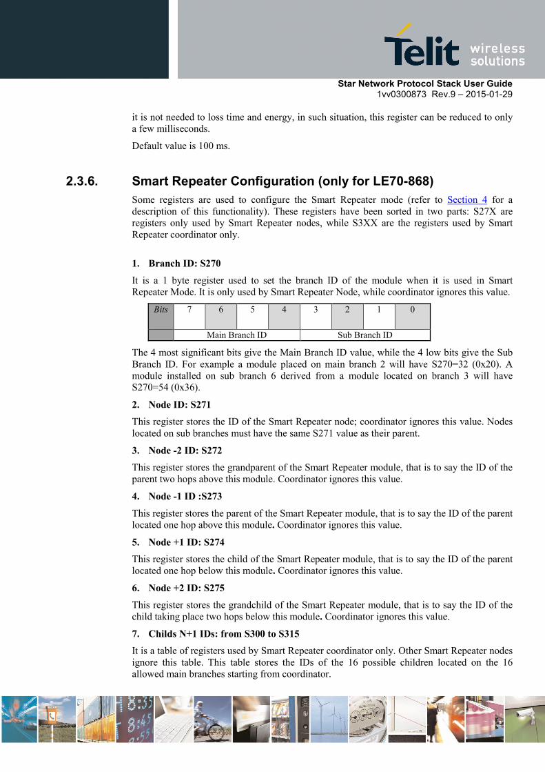
1. Branch ID: S270
It is a 1 byte register used to set the branch ID of the module when it is used in Smart Repeater Mode. It is only used by Smart Repeater Node, while coordinator ignores this value.
Bits 7 6 5 4 3 2 1 0
Main Branch ID Sub Branch ID
The 4 most significant bits give the Main Branch ID value, while the 4 low bits give the Sub Branch ID. For example a module placed on main branch 2 will have S270=32 (0x20). A module installed on sub branch 6 derived from a module located on branch 3 will have S270=54 (0x36).
2. Node ID: S271
This register stores the ID of the Smart Repeater node; coordinator ignores this value. Nodes located on sub branches must have the same S271 value as their parent.
3. Node -2 ID: S272
This register stores the grandparent of the Smart Repeater module, that is to say the ID of the parent two hops above this module. Coordinator ignores this value.
4. Node -1 ID :S273
This register stores the parent of the Smart Repeater module, that is to say the ID of the parent located one hop above this module. Coordinator ignores this value.
5. Node +1 ID: S274
This register stores the child of the Smart Repeater module, that is to say the ID of the parent located one hop below this module. Coordinator ignores this value.
6. Node +2 ID: S275
This register stores the grandchild of the Smart Repeater module, that is to say the ID of the child taking place two hops below this module. Coordinator ignores this value.
7. Childs N+1 IDs: from S300 to S315
It is a table of registers used by Smart Repeater coordinator only. Other Smart Repeater nodes ignore this table. This table stores the IDs of the 16 possible children located on the 16 allowed main branches starting from coordinator.

Star Network Protocol Stack User Guide 1vv0300873 Rev.9 – 2015-01-29
Reproduction forbidden without written authorization from Telit Communications S.p.A.- All Rights Reserved. Page 30 of 66
8. Childs N+2 IDs: from S316 to S331
It is a table of registers used by Smart Repeater coordinator only. Other Smart Repeater nodes ignore this table. This table stores the IDs of the 16 possible grandchildren located on the 16 allowed main branches starting from coordinator.
Star Network Protocol Stack User Guide 1vv0300873 Rev.9 – 2015-01-29
Reproduction forbidden without written authorization from Telit Communications S.p.A.- All Rights Reserved. Page 31 of 66
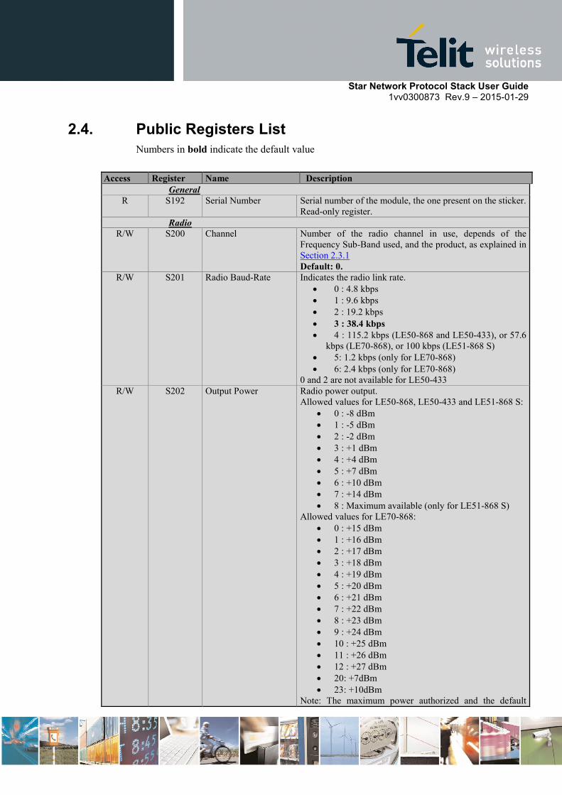
2.4. Public Registers List Numbers in bold indicate the default value
Access Register Name Description General
R S192 Serial Number Serial number of the module, the one present on the sticker. Read-only register.
Radio R/W S200 Channel Number of the radio channel in use, depends of the
Frequency Sub-Band used, and the product, as explained in Section 2.3.1 Default: 0.
R/W S201 Radio Baud-Rate Indicates the radio link rate. 0 : 4.8 kbps 1 : 9.6 kbps 2 : 19.2 kbps
3 : 38.4 kbps 4 : 115.2 kbps (LE50-868 and LE50-433), or 57.6
kbps (LE70-868), or 100 kbps (LE51-868 S) 5: 1.2 kbps (only for LE70-868) 6: 2.4 kbps (only for LE70-868)
0 and 2 are not available for LE50-433 R/W S202 Output Power Radio power output.
Allowed values for LE50-868, LE50-433 and LE51-868 S: 0 : -8 dBm 1 : -5 dBm 2 : -2 dBm 3 : +1 dBm 4 : +4 dBm 5 : +7 dBm 6 : +10 dBm 7 : +14 dBm 8 : Maximum available (only for LE51-868 S)
Allowed values for LE70-868: 0 : +15 dBm 1 : +16 dBm 2 : +17 dBm 3 : +18 dBm 4 : +19 dBm 5 : +20 dBm 6 : +21 dBm 7 : +22 dBm 8 : +23 dBm 9 : +24 dBm 10 : +25 dBm 11 : +26 dBm 12 : +27 dBm 20: +7dBm 23: +10dBm
Note: The maximum power authorized and the default
Star Network Protocol Stack User Guide 1vv0300873 Rev.9 – 2015-01-29
Reproduction forbidden without written authorization from Telit Communications S.p.A.- All Rights Reserved. Page 32 of 66
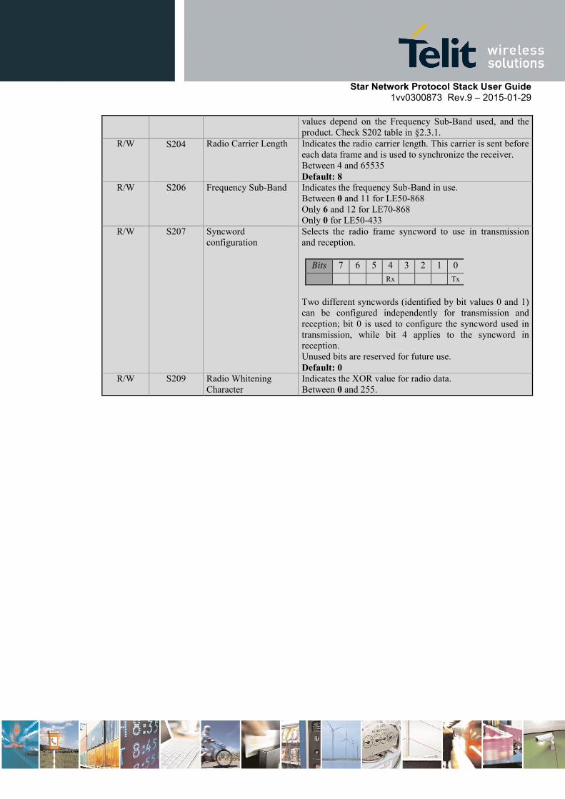
values depend on the Frequency Sub-Band used, and the product. Check S202 table in §2.3.1.
R/W S204 Radio Carrier Length Indicates the radio carrier length. This carrier is sent before each data frame and is used to synchronize the receiver. Between 4 and 65535 Default: 8
R/W S206 Frequency Sub-Band Indicates the frequency Sub-Band in use. Between 0 and 11 for LE50-868 Only 6 and 12 for LE70-868 Only 0 for LE50-433
R/W S207 Syncword configuration
Selects the radio frame syncword to use in transmission and reception.
Bits 7 6 5 4 3 2 1 0
Rx Tx
Two different syncwords (identified by bit values 0 and 1) can be configured independently for transmission and reception; bit 0 is used to configure the syncword used in transmission, while bit 4 applies to the syncword in reception. Unused bits are reserved for future use. Default: 0
R/W S209 Radio Whitening Character
Indicates the XOR value for radio data. Between 0 and 255.
Star Network Protocol Stack User Guide 1vv0300873 Rev.9 – 2015-01-29
Reproduction forbidden without written authorization from Telit Communications S.p.A.- All Rights Reserved. Page 33 of 66
Access Register Name Description
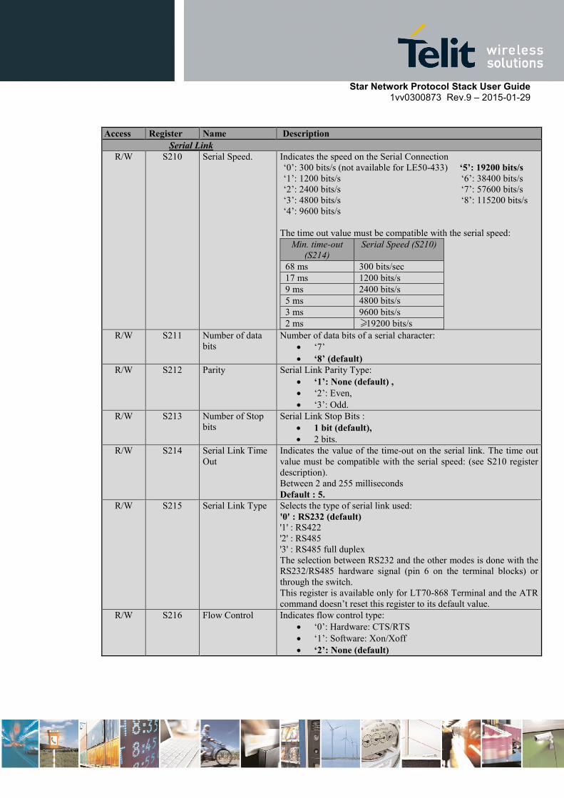
Serial Link R/W
S210 Serial Speed.
Indicates the speed on the Serial Connection ‘0’: 300 bits/s (not available for LE50-433) ‘5’: 19200 bits/s ‘1’: 1200 bits/s ‘6’: 38400 bits/s ‘2’: 2400 bits/s ‘7’: 57600 bits/s ‘3’: 4800 bits/s ‘8’: 115200 bits/s ‘4’: 9600 bits/s
The time out value must be compatible with the serial speed:
Min. time-out (S214)
Serial Speed (S210)
68 ms 300 bits/sec 17 ms 1200 bits/s 9 ms 2400 bits/s 5 ms 4800 bits/s 3 ms 9600 bits/s 2 ms 19200 bits/s
R/W S211 Number of data bits
Number of data bits of a serial character: ‘7’
‘8’ (default) R/W S212 Parity Serial Link Parity Type:
‘1’: None (default) , ‘2’: Even, ‘3’: Odd.
R/W S213 Number of Stop bits
Serial Link Stop Bits : 1 bit (default), 2 bits.
R/W S214 Serial Link Time Out
Indicates the value of the time-out on the serial link. The time out value must be compatible with the serial speed: (see S210 register description). Between 2 and 255 milliseconds Default : 5.
R/W S215 Serial Link Type Selects the type of serial link used: '0' : RS232 (default) '1' : RS422 '2' : RS485 '3' : RS485 full duplex The selection between RS232 and the other modes is done with the RS232/RS485 hardware signal (pin 6 on the terminal blocks) or through the switch. This register is available only for LT70-868 Terminal and the ATR command doesn’t reset this register to its default value.
R/W S216 Flow Control Indicates flow control type: ‘0’: Hardware: CTS/RTS ‘1’: Software: Xon/Xoff ‘2’: None (default)
Star Network Protocol Stack User Guide 1vv0300873 Rev.9 – 2015-01-29
Reproduction forbidden without written authorization from Telit Communications S.p.A.- All Rights Reserved. Page 34 of 66
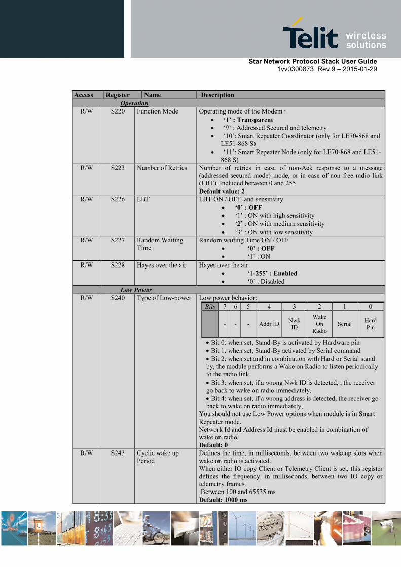
Access Register Name Description
Operation R/W S220 Function Mode Operating mode of the Modem :
‘1’ : Transparent ‘9’ : Addressed Secured and telemetry ‘10’: Smart Repeater Coordinator (only for LE70-868 and
LE51-868 S) ‘11’: Smart Repeater Node (only for LE70-868 and LE51-
868 S) R/W S223 Number of Retries Number of retries in case of non-Ack response to a message
(addressed secured mode) mode, or in case of non free radio link (LBT). Included between 0 and 255 Default value: 2
R/W S226 LBT LBT ON / OFF, and sensitivity
‘0’ : OFF ‘1’ : ON with high sensitivity ‘2’ : ON with medium sensitivity ‘3’ : ON with low sensitivity
R/W S227 Random Waiting Time
Random waiting Time ON / OFF
‘0’ : OFF ‘1’ : ON
R/W S228 Hayes over the air Hayes over the air ‘1-255’ : Enabled ‘0’ : Disabled
Low Power R/W S240 Type of Low-power Low power behavior:
Bits 7 6 5 4 3 2 1 0
- - - Addr ID Nwk ID
Wake On
Radio Serial
Hard Pin
Bit 0: when set, Stand-By is activated by Hardware pin Bit 1: when set, Stand-By activated by Serial command Bit 2: when set and in combination with Hard or Serial stand by, the module performs a Wake on Radio to listen periodically to the radio link. Bit 3: when set, if a wrong Nwk ID is detected, , the receiver go back to wake on radio immediately. Bit 4: when set, if a wrong address is detected, the receiver go back to wake on radio immediately,
You should not use Low Power options when module is in Smart Repeater mode. Network Id and Address Id must be enabled in combination of wake on radio. Default: 0
R/W S243 Cyclic wake up Period
Defines the time, in milliseconds, between two wakeup slots when wake on radio is activated. When either IO copy Client or Telemetry Client is set, this register defines the frequency, in milliseconds, between two IO copy or telemetry frames. Between 100 and 65535 ms Default: 1000 ms
Star Network Protocol Stack User Guide 1vv0300873 Rev.9 – 2015-01-29
Reproduction forbidden without written authorization from Telit Communications S.p.A.- All Rights Reserved. Page 35 of 66
R/W S245 Wake on Radio Duration
Defines the time, in milliseconds, during which the module will listen to the radio when wake on radio is activated. If no radio activity is detected during this time, the module resume to stand by. Between 1 and 255 ms Default: 10 ms
R/W S247 Stand-by Timeout
Defines the timeout, in milliseconds, after which the module returns to stand by when a radio carrier is detected but no valid frame is received. This duration has to be set in accordance with the preamble length of the sender. Between 10 and 65535 ms Default: 100 ms
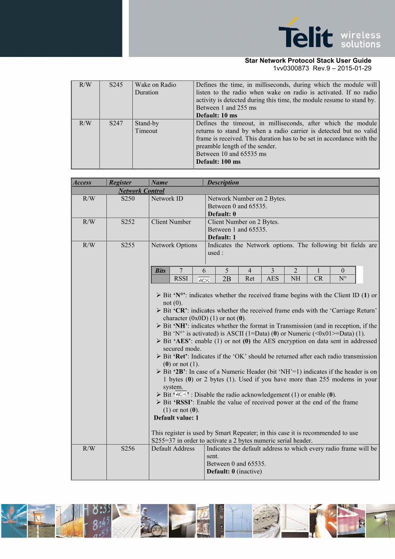
Access Register Name Description
Network Control R/W S250
Network ID Network Number on 2 Bytes.
Between 0 and 65535. Default: 0
R/W S252 Client Number Client Number on 2 Bytes. Between 1 and 65535. Default: 1
R/W S255 Network Options Indicates the Network options. The following bit fields are used :
Bit ‘N°’: indicates whether the received frame begins with the Client ID (1) or
not (0). Bit ‘CR’: indicates whether the received frame ends with the ‘Carriage Return’
character (0x0D) (1) or not (0). Bit ‘NH’: indicates whether the format in Transmission (and in reception, if the
Bit ‘N°’ is activated) is ASCII (1=Data) (0) or Numeric (<0x01>=Data) (1). Bit ‘AES’: enable (1) or not (0) the AES encryption on data sent in addressed
secured mode. Bit ‘Ret’: Indicates if the ‘OK’ should be returned after each radio transmission
(0) or not (1). Bit ‘2B’: In case of a Numeric Header (bit ‘NH’=1) indicates if the header is on
1 bytes (0) or 2 bytes (1). Used if you have more than 255 modems in your system.
Bit ‘ ’ : Disable the radio acknowledgement (1) or enable (0). Bit ‘RSSI’: Enable the value of received power at the end of the frame
(1) or not (0). Default value: 1
This register is used by Smart Repeater; in this case it is recommended to use S255=37 in order to activate a 2 bytes numeric serial header.
R/W S256 Default Address Indicates the default address to which every radio frame will be sent. Between 0 and 65535. Default: 0 (inactive)
Bits 7 6 5 4 3 2 1 0 RSSI 2B Ret AES NH CR N°
Star Network Protocol Stack User Guide 1vv0300873 Rev.9 – 2015-01-29
Reproduction forbidden without written authorization from Telit Communications S.p.A.- All Rights Reserved. Page 36 of 66
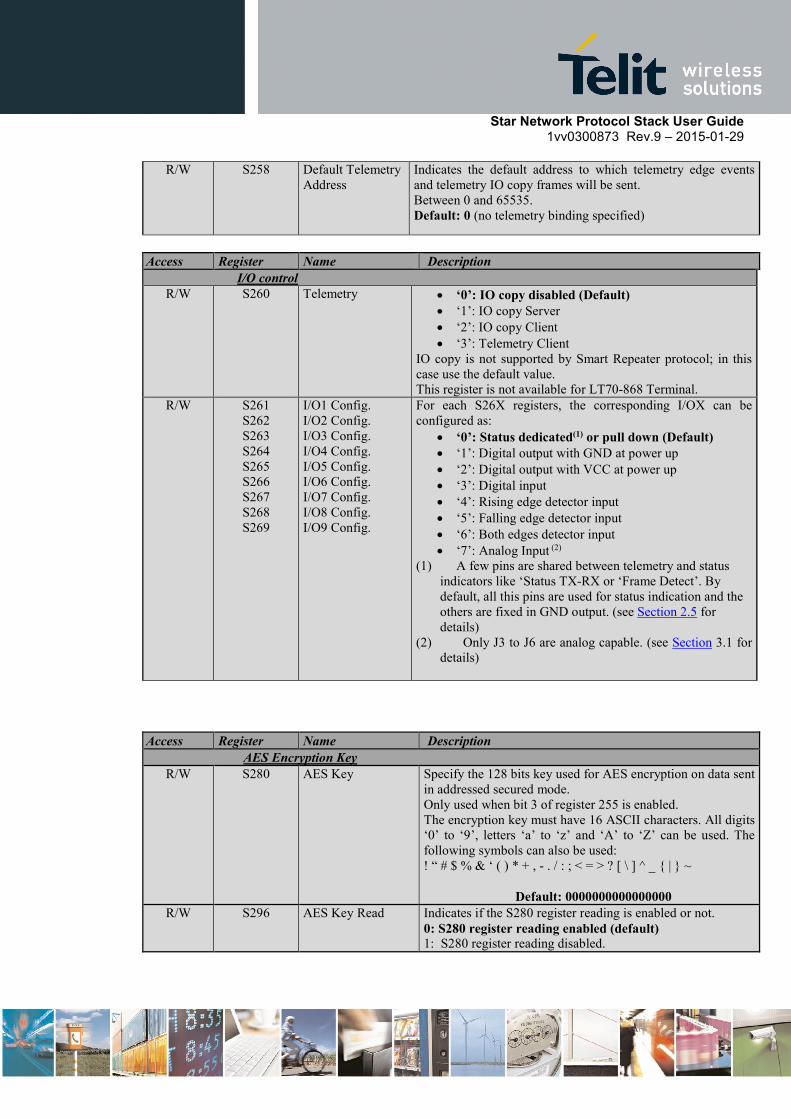
R/W S258 Default Telemetry Address
Indicates the default address to which telemetry edge events and telemetry IO copy frames will be sent. Between 0 and 65535. Default: 0 (no telemetry binding specified)
Access Register Name Description
I/O control R/W S260 Telemetry ‘0’: IO copy disabled (Default)
‘1’: IO copy Server ‘2’: IO copy Client ‘3’: Telemetry Client
IO copy is not supported by Smart Repeater protocol; in this case use the default value. This register is not available for LT70-868 Terminal.
R/W S261 S262 S263 S264 S265 S266 S267 S268 S269
I/O1 Config. I/O2 Config. I/O3 Config. I/O4 Config. I/O5 Config. I/O6 Config. I/O7 Config. I/O8 Config. I/O9 Config.
For each S26X registers, the corresponding I/OX can be configured as:
‘0’: Status dedicated(1) or pull down (Default) ‘1’: Digital output with GND at power up ‘2’: Digital output with VCC at power up ‘3’: Digital input ‘4’: Rising edge detector input ‘5’: Falling edge detector input ‘6’: Both edges detector input ‘7’: Analog Input (2)
(1) A few pins are shared between telemetry and status indicators like ‘Status TX-RX or ‘Frame Detect’. By default, all this pins are used for status indication and the others are fixed in GND output. (see Section 2.5 for details)
(2) Only J3 to J6 are analog capable. (see Section 3.1 for details)
Access Register Name Description
AES Encryption Key R/W S280 AES Key Specify the 128 bits key used for AES encryption on data sent
in addressed secured mode. Only used when bit 3 of register 255 is enabled. The encryption key must have 16 ASCII characters. All digits ‘0’ to ‘9’, letters ‘a’ to ‘z’ and ‘A’ to ‘Z’ can be used. The following symbols can also be used: ! “ # $ % & ‘ ( ) * + , - . / : ; < = > ? [ \ ] ^ _ { | } ~
Default: 0000000000000000 R/W S296 AES Key Read Indicates if the S280 register reading is enabled or not.
0: S280 register reading enabled (default) 1: S280 register reading disabled.
Star Network Protocol Stack User Guide 1vv0300873 Rev.9 – 2015-01-29
Reproduction forbidden without written authorization from Telit Communications S.p.A.- All Rights Reserved. Page 37 of 66
Access Register Name Description
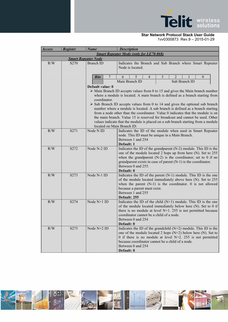
Smart Repeater Mode (only for LE70-868)
Smart Repeater Node R/W S270 Branch ID Indicates the Branch and Sub Branch where Smart Repeater
Node is located.
Default value: 0 Main Branch ID accepts values from 0 to 15 and gives the Main branch number
where a module is located. A main branch is defined as a branch starting from coordinator.
Sub Branch ID accepts values from 0 to 14 and gives the optional sub branch number where a module is located. A sub branch is defined as a branch starting from a node other than the coordinator. Value 0 indicates that the module is on the main branch. Value 15 is reserved for broadcast and cannot be used. Other values indicate that the module is placed on a sub branch starting from a module located on Main Branch ID.
R/W S271 Node N ID Indicates the ID of the module when used in Smart Repeater node. This ID must be unique in a Main Branch. Between 1 and 254 Default: 1
R/W S272 Node N-2 ID Indicates the ID of the grandparent (N-2) module. This ID is the one of the module located 2 hops up from here (N). Set to 255 when the grandparent (N-2) is the coordinator; set to 0 if no grandparent exists in case of parent (N-1) is the coordinator. Between 0 and 255. Default: 0
R/W S273 Node N-1 ID Indicates the ID of the parent (N-1) module. This ID is the one of the module located immediately above here (N). Set to 255 when the parent (N-1) is the coordinator. 0 is not allowed because a parent must exist. Between 1 and 255 Default: 255
R/W S274 Node N+1 ID Indicates the ID of the child (N+1) module. This ID is the one of the module located immediately below here (N). Set to 0 if there is no module at level N+1. 255 is not permitted because coordinator cannot be a child of a node. Between 0 and 254 Default: 0
R/W S275 Node N+2 ID Indicates the ID of the grandchild (N+2) module. This ID is the one of the module located 2 hops (N+2) below here (N). Set to 0 if there is no module at level N+2. 255 is not permitted because coordinator cannot be a child of a node. Between 0 and 254 Default: 0
Bits 7 6 5 4 3 2 1 0 Main Branch ID Sub Branch ID
NH
Star Network Protocol Stack User Guide 1vv0300873 Rev.9 – 2015-01-29
Reproduction forbidden without written authorization from Telit Communications S.p.A.- All Rights Reserved. Page 38 of 66
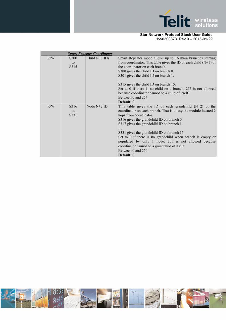
Smart Repeater Coordinator
R/W S300 to
S315
Child N+1 IDs Smart Repeater mode allows up to 16 main branches starting from coordinator. This table gives the ID of each child (N+1) of the coordinator on each branch. S300 gives the child ID on branch 0. S301 gives the child ID on branch 1. … S315 gives the child ID on branch 15. Set to 0 if there is no child on a branch. 255 is not allowed because coordinator cannot be a child of itself Between 0 and 254 Default: 0
R/W S316 to
S331
Node N+2 ID This table gives the ID of each grandchild (N+2) of the coordinator on each branch. That is to say the module located 2 hops from coordinator. S316 gives the grandchild ID on branch 0. S317 gives the grandchild ID on branch 1. … S331 gives the grandchild ID on branch 15. Set to 0 if there is no grandchild when branch is empty or populated by only 1 node. 255 is not allowed because coordinator cannot be a grandchild of itself. Between 0 and 254 Default: 0
Star Network Protocol Stack User Guide 1vv0300873 Rev.9 – 2015-01-29
Reproduction forbidden without written authorization from Telit Communications S.p.A.- All Rights Reserved. Page 39 of 66
2.5. Dedicated IO description. Four IOs of LE50-868 are dedicated to inform device status and happening events. These signals (output) are activated by default but the user can use these pins for other telemetry usage by configuring registers S261 to S269. Refer to [5] for detailed hardware description of Ios.
2.5.1. TX LED (IO1)
When register S261=0, this output signal is set to VCC during radio transmission and stay to GND the rest of the time. It is switched for all kind of radio transmissions including ACK, repetitions and radio tests.
2.5.2. RX LED (IO2)
When register S262=0, this output signal is set to VCC as soon as a radio frame is detected with correct synchronization word. The signal returns to GND as soon as the frame reception is finished. This signal is the equivalent of “Frame Detect” on old Telit products.
Note that this signal switches at low level before application layer treatment, that is to say that the signal goes to VCC even if a frame has not the correct network number or doesn’t match the destination ID.
2.5.3. ACK TX (IO8)
Activated when S268=0.
In Addressed Secured mode, this signal rises to VCC when an ACK hasn’t been received after frame transmission and repetition. This is the hardware version of “ERROR” serial message. It stays at VCC until next success addressed secured transmission.
If IO copy is set to server (S260=1), ACK TX rises to VCC when an IO copy client loss has been detected. In this case, the signal stays at VCC during 1 second.
2.5.4. Status RX/TX (IO9)
When register S269=0, this signal indicates the status of the serial port. When serial port is transmitting, Status RX/TX signal goes VCC until the end of serial transmission. The signal stays to GND the rest of the time. It is particularly useful to drive a RS232/485 converter.

Star Network Protocol Stack User Guide 1vv0300873 Rev.9 – 2015-01-29
Reproduction forbidden without written authorization from Telit Communications S.p.A.- All Rights Reserved. Page 40 of 66
2.6. Hayes over the air It is possible to enter the configuration mode of a remote module using a local one to forward Hayes commands over the air and receive responses from the remote module.
2.6.1. Requirements
To send Hayes commands over the air, you have to know the 11 characters serial number of the remote module and also the current radio configuration of the remote module: band, channel and RF data rate.
2.6.2. How to start Hayes over the air
First enter the configuration mode of the local module by sending normal ‘+++’ serial frame.
Set up the local module in order to match the radio configuration of the remote one : band, channel and RF data rate must be the same as in the remote module.
Set the local module in Transparent mode (ATS220=1) Exit from configuration mode of the local module by sending ATO. Use the local module to send on the air the following frame ‘+++xxxxxxxxxxx’ that is to
say ‘+++’ concatenated with the 11 characters of the remote module serial number. The frame must be sent at once without any delay between characters.
If you receive an “OK” back, this means that you have correctly entered the configuration mode of the remote module. If you don’t receive any response, make sure that the serial number is correct and that you are in the range of the remote module.
You can now send any classic Hayes command to the remote module. You can confirm this state by asking the serial number sending “ATS192?” the remote module should reply with its own serial number confirming that you are currently configuring the desired module. Each command must be sent in on shot without delay between characters. Now, for example you can change the serial data rate by sending ATS210=4;
Local module
Remote module to be configured
Settings are sent through the air without any physical
access to the remote device

Star Network Protocol Stack User Guide 1vv0300873 Rev.9 – 2015-01-29
Reproduction forbidden without written authorization from Telit Communications S.p.A.- All Rights Reserved. Page 41 of 66
this will turn the com port of the remote module to 9600bds. All Hayes commands sent over the air are replied normally like in local mode.
When you have completed the remote configuration, simply send ATO to exit the remote configuration mode. The remote module sends OK back and resumes the operating mode using the new configuration.
2.6.3. Particular case
Hayes over the air also allows acting on the radio configuration of the remote module. But in this case, each parameter modified on the remote module must also be applied locally. For example, to change the radio channel from 0 to 1, send ‘+++xxxxxxxxxxx’ to enter the configuration mode of the remote module, send ‘ATS200=1’ to change the radio channel of the remote module, remote module sends OK on channel 0 and then immediately applies the new channel. At this step, remote module is already on channel 1 while local module is still on channel 0. Send ‘+++’ to enter the local configuration mode, send ‘ATS200=1’ to change the local channel, send ‘ATO’ to exit from configuration mode of the local module. Now both modules share the same channel and you can continue the remote configuration or close it by sending ‘ATO’. This procedure is the same for each parameter affecting the radio link (band, channel, data rate). Finally, it is also possible to trig remotely some radio test by sending ATT0 or ATT1. In this case, the radio test automatically stops after 30 seconds on the remote module in order to recover the communication with the local module.
Star Network Protocol Stack User Guide 1vv0300873 Rev.9 – 2015-01-29
Reproduction forbidden without written authorization from Telit Communications S.p.A.- All Rights Reserved. Page 42 of 66
3. Description of Telemetry Functionalities
This Chapter is dedicated to the telemetry functionality of the Star Network protocol stack. It allows functional use of I/Os of the module.
WARNING: Telemetry functionalities are not available in LT70-868 Terminal.
3.1. General Features
Telemetry protocol is based on the addressed secured operating mode. Each module is able to execute telemetry orders while exchanging serial data.
o 9 pins of the module are dedicated for I/O use, with different capability :
o Standard digital In / Out
o IRQ Input to automatically send a frame on edge event
o 12 bits analog inputs capable, readable either locally or remotely
I/O copy is available between 2 modules or more in star architecture to update digital output according to digital input from another module.
Independent I/O and data binding is possible to route data and I/O frame to different targets.
9 pins are available for user telemetry application. All pins are digital I/O capable and some pin has specific functionalities shown in the following table.
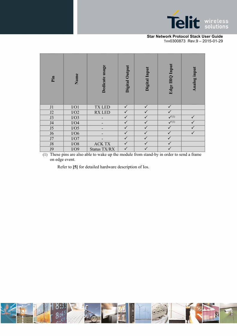
Star Network Protocol Stack User Guide 1vv0300873 Rev.9 – 2015-01-29
Reproduction forbidden without written authorization from Telit Communications S.p.A.- All Rights Reserved. Page 43 of 66
P
in
Na
me
Ded
icat
e u
sag
e
Dig
ita
l O
utp
ut
Dig
ita
l In
pu
t
Ed
ge
IRQ
In
pu
t
An
alo
g i
np
ut
J1 I/O1 TX LED J2 I/O2 RX LED J3 I/O3 - (1) J4 I/O4 - (1) J5 I/O5 - J6 I/O6 - J7 I/O7 - J8 I/O8 ACK TX J9 I/O9 Status TX/RX
(1) These pins are also able to wake up the module from stand-by in order to send a frame on edge event.
Refer to [5] for detailed hardware description of Ios.
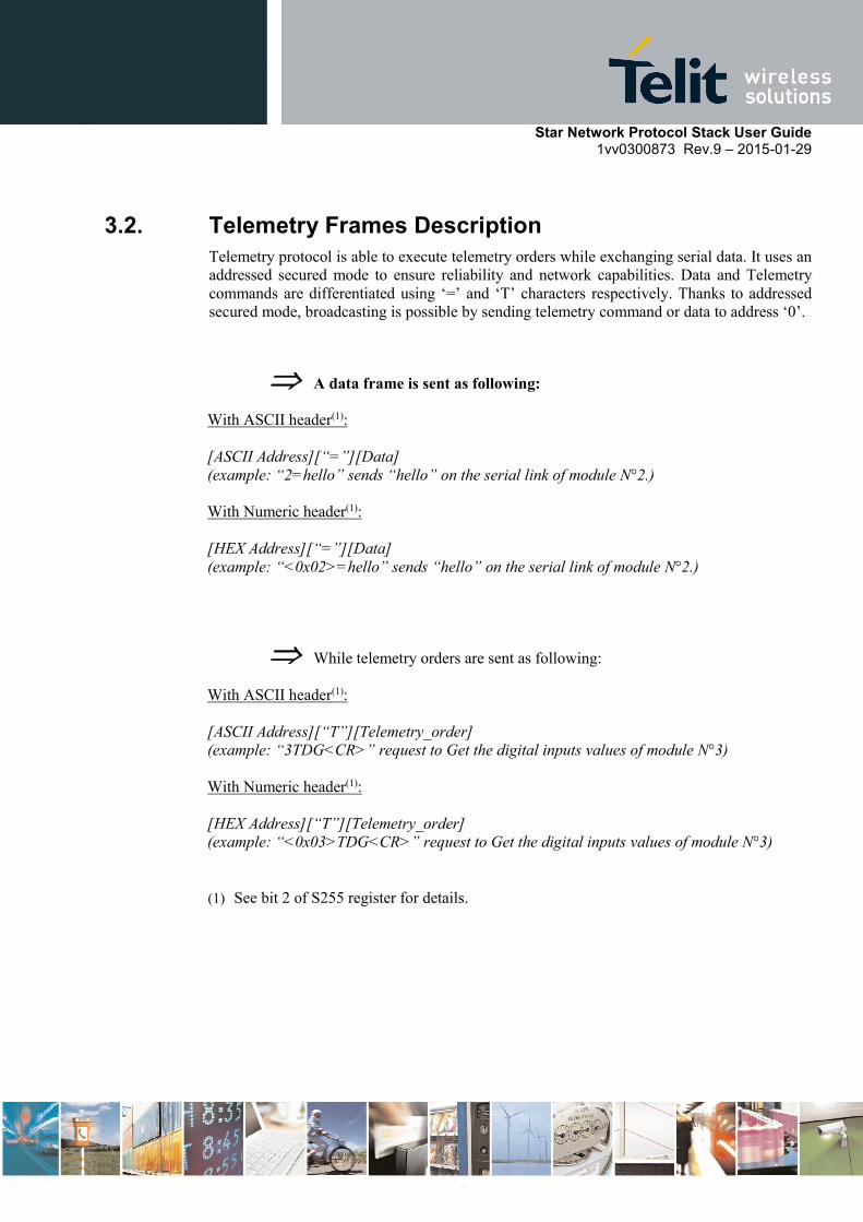
Star Network Protocol Stack User Guide 1vv0300873 Rev.9 – 2015-01-29
Reproduction forbidden without written authorization from Telit Communications S.p.A.- All Rights Reserved. Page 44 of 66
3.2. Telemetry Frames Description Telemetry protocol is able to execute telemetry orders while exchanging serial data. It uses an addressed secured mode to ensure reliability and network capabilities. Data and Telemetry commands are differentiated using ‘=’ and ‘T’ characters respectively. Thanks to addressed secured mode, broadcasting is possible by sending telemetry command or data to address ‘0’.
A data frame is sent as following: With ASCII header(1): [ASCII Address][“=”][Data] (example: “2=hello” sends “hello” on the serial link of module N°2.) With Numeric header(1): [HEX Address][“=”][Data] (example: “<0x02>=hello” sends “hello” on the serial link of module N°2.)
While telemetry orders are sent as following: With ASCII header(1): [ASCII Address][“T”][Telemetry_order] (example: “3TDG<CR>” request to Get the digital inputs values of module N°3) With Numeric header(1): [HEX Address][“T”][Telemetry_order] (example: “<0x03>TDG<CR>” request to Get the digital inputs values of module N°3)
(1) See bit 2 of S255 register for details.
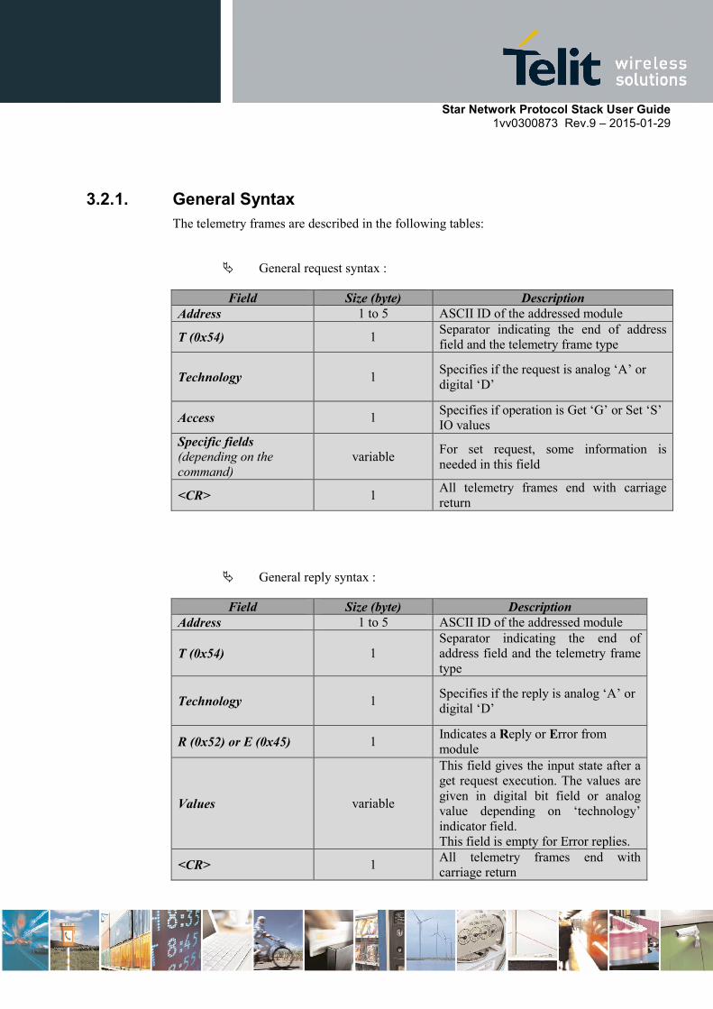
Star Network Protocol Stack User Guide 1vv0300873 Rev.9 – 2015-01-29
Reproduction forbidden without written authorization from Telit Communications S.p.A.- All Rights Reserved. Page 45 of 66
3.2.1. General Syntax
The telemetry frames are described in the following tables:
General request syntax :
Field Size (byte) Description Address 1 to 5 ASCII ID of the addressed module
T (0x54) 1 Separator indicating the end of address field and the telemetry frame type
Technology 1 Specifies if the request is analog ‘A’ or digital ‘D’
Access 1 Specifies if operation is Get ‘G’ or Set ‘S’ IO values
Specific fields (depending on the command)
variable For set request, some information is needed in this field
<CR> 1 All telemetry frames end with carriage return
General reply syntax :
Field Size (byte) Description Address 1 to 5 ASCII ID of the addressed module
T (0x54) 1 Separator indicating the end of address field and the telemetry frame type
Technology 1 Specifies if the reply is analog ‘A’ or digital ‘D’
R (0x52) or E (0x45) 1 Indicates a Reply or Error from module
Values variable
This field gives the input state after a get request execution. The values are given in digital bit field or analog value depending on ‘technology’ indicator field. This field is empty for Error replies.
<CR> 1 All telemetry frames end with carriage return
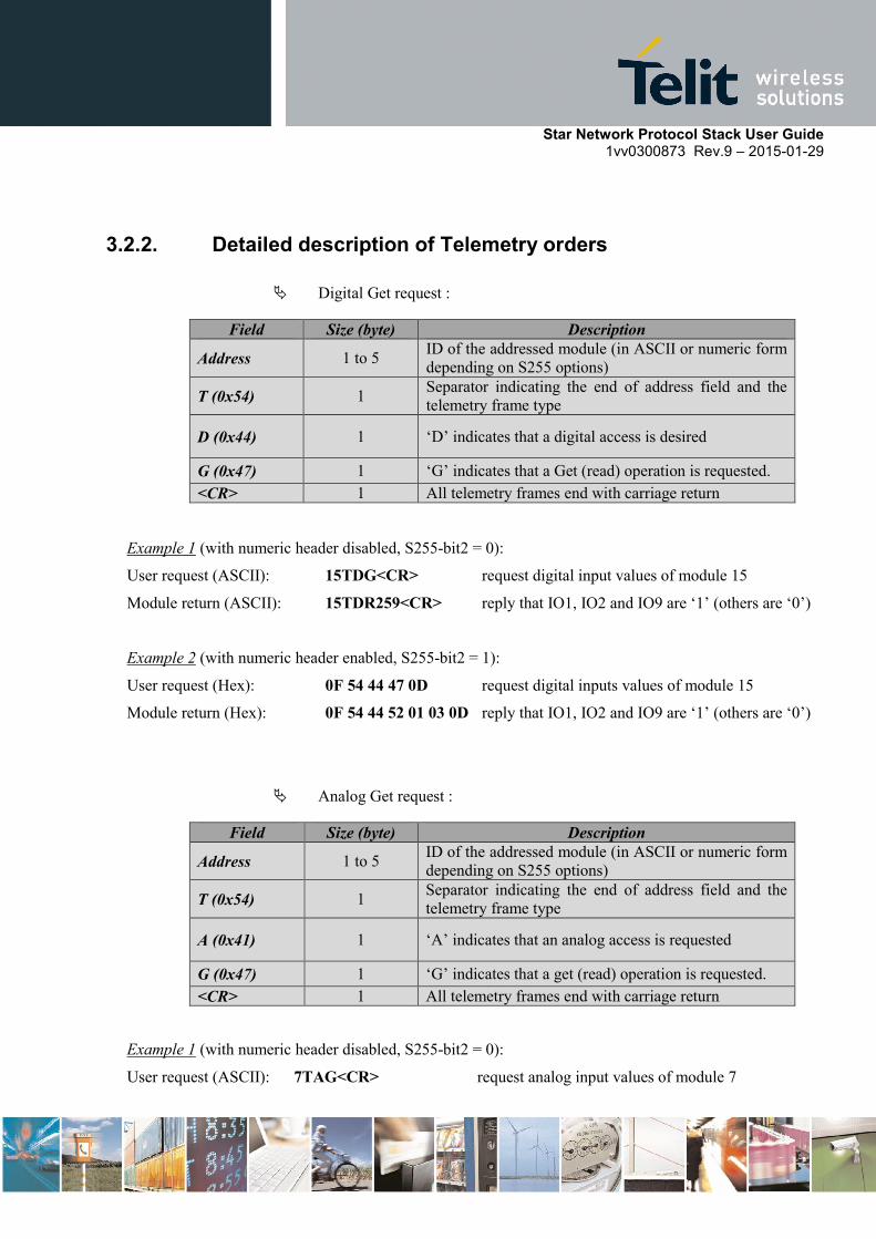
Star Network Protocol Stack User Guide 1vv0300873 Rev.9 – 2015-01-29
Reproduction forbidden without written authorization from Telit Communications S.p.A.- All Rights Reserved. Page 46 of 66
3.2.2. Detailed description of Telemetry orders
Digital Get request :
Field Size (byte) Description
Address 1 to 5 ID of the addressed module (in ASCII or numeric form depending on S255 options)
T (0x54) 1 Separator indicating the end of address field and the telemetry frame type
D (0x44) 1 ‘D’ indicates that a digital access is desired
G (0x47) 1 ‘G’ indicates that a Get (read) operation is requested.
<CR> 1 All telemetry frames end with carriage return
Example 1 (with numeric header disabled, S255-bit2 = 0):
User request (ASCII): 15TDG<CR> request digital input values of module 15
Module return (ASCII): 15TDR259<CR> reply that IO1, IO2 and IO9 are ‘1’ (others are ‘0’)
Example 2 (with numeric header enabled, S255-bit2 = 1):
User request (Hex): 0F 54 44 47 0D request digital inputs values of module 15
Module return (Hex): 0F 54 44 52 01 03 0D reply that IO1, IO2 and IO9 are ‘1’ (others are ‘0’)
Analog Get request :
Field Size (byte) Description
Address 1 to 5 ID of the addressed module (in ASCII or numeric form depending on S255 options)
T (0x54) 1 Separator indicating the end of address field and the telemetry frame type
A (0x41) 1 ‘A’ indicates that an analog access is requested
G (0x47) 1 ‘G’ indicates that a get (read) operation is requested.
<CR> 1 All telemetry frames end with carriage return
Example 1 (with numeric header disabled, S255-bit2 = 0):
User request (ASCII): 7TAG<CR> request analog input values of module 7
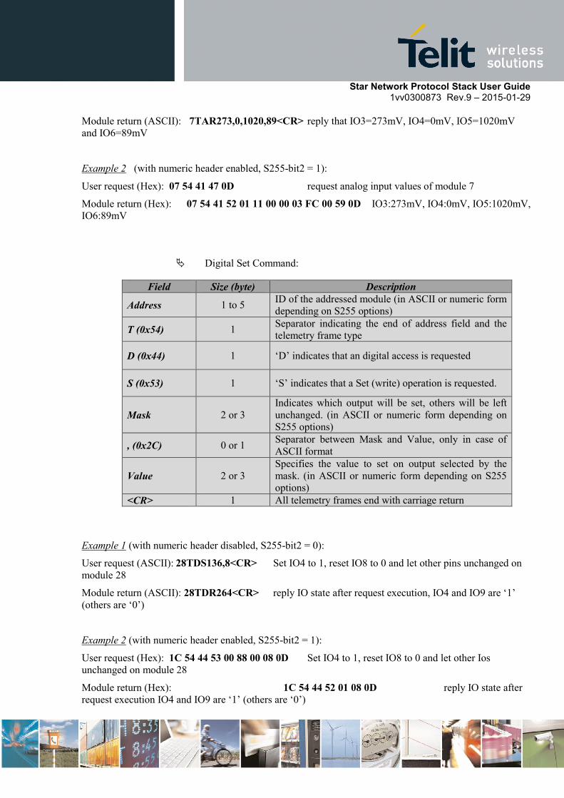
Star Network Protocol Stack User Guide 1vv0300873 Rev.9 – 2015-01-29
Reproduction forbidden without written authorization from Telit Communications S.p.A.- All Rights Reserved. Page 47 of 66
Module return (ASCII): 7TAR273,0,1020,89<CR> reply that IO3=273mV, IO4=0mV, IO5=1020mV and IO6=89mV
Example 2 (with numeric header enabled, S255-bit2 = 1):
User request (Hex): 07 54 41 47 0D request analog input values of module 7
Module return (Hex): 07 54 41 52 01 11 00 00 03 FC 00 59 0D IO3:273mV, IO4:0mV, IO5:1020mV, IO6:89mV
Digital Set Command:
Field Size (byte) Description
Address 1 to 5 ID of the addressed module (in ASCII or numeric form depending on S255 options)
T (0x54) 1 Separator indicating the end of address field and the telemetry frame type
D (0x44) 1 ‘D’ indicates that an digital access is requested
S (0x53) 1 ‘S’ indicates that a Set (write) operation is requested.
Mask 2 or 3 Indicates which output will be set, others will be left unchanged. (in ASCII or numeric form depending on S255 options)
, (0x2C) 0 or 1 Separator between Mask and Value, only in case of ASCII format
Value 2 or 3 Specifies the value to set on output selected by the mask. (in ASCII or numeric form depending on S255 options)
<CR> 1 All telemetry frames end with carriage return
Example 1 (with numeric header disabled, S255-bit2 = 0):
User request (ASCII): 28TDS136,8<CR> Set IO4 to 1, reset IO8 to 0 and let other pins unchanged on module 28
Module return (ASCII): 28TDR264<CR> reply IO state after request execution, IO4 and IO9 are ‘1’ (others are ‘0’)
Example 2 (with numeric header enabled, S255-bit2 = 1):
User request (Hex): 1C 54 44 53 00 88 00 08 0D Set IO4 to 1, reset IO8 to 0 and let other Ios unchanged on module 28
Module return (Hex): 1C 54 44 52 01 08 0D reply IO state after request execution IO4 and IO9 are ‘1’ (others are ‘0’)
Star Network Protocol Stack User Guide 1vv0300873 Rev.9 – 2015-01-29
Reproduction forbidden without written authorization from Telit Communications S.p.A.- All Rights Reserved. Page 48 of 66
NOTE: If user attempts to write a non existent output (Mask> 511) a digital error is returned. Example: ‘1TDE<CR>’.
3.2.3. Interruptible Inputs
All inputs are interruptible capable. That is to say, they are able to detect a rising edge or a falling one or both depending of the configuration. To use this function, the input should be declared as ‘Rising edge detector input’, ‘Falling edge detector input’ or ‘Both edges detector input’ in register 261 to 269.
When enabled, an edge event on those pins automatically sends a telemetry frame to the default client chosen in S258 register. The frame sent is the same as the one returned after a digital read request. Of course the address set in S258 register can be the address of the local module (S258=S252) in this case, all edge events are reported on the serial link of the local module.
In addition, IO3 and IO4 are also able to detect edge even if module is in stand by mode. In this case, when an edge occurs, the module first wakes up and then sends the telemetry frame to the default telemetry address specified in register 258.
3.2.4. Telemetry Client
The Telemetry Client functionality is selected by setting S260 to 3. A telemetry client sends periodically a telemetry frame containing its IO status to the module specified in the S258 register. The format of the telemetry frame is the same as that used in a response to a digital read request. The update period is chosen by S243 register from 100 to 65535 ms.
3.3. IO Copy “IO Copy” is the capacity to automatically set the outputs of a module according to the inputs of a remote module and vice versa. In this case, the modules are autonomous without the need of a controller.
3.3.1. General Usage
The IO Copy feature can be used either in point to point architecture or in a star network. In all cases, IO copy requires the use of one IO server (S260=1) and one or more IO clients (S260=2).
Each client sends periodically its input values to the server (specified in S258 register) and waits for server input values coming back to update its local outputs.
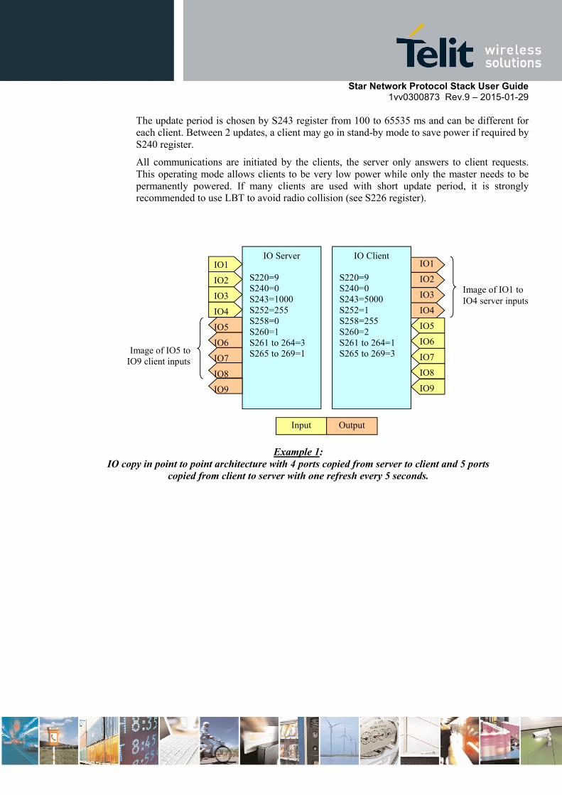
Star Network Protocol Stack User Guide 1vv0300873 Rev.9 – 2015-01-29
Reproduction forbidden without written authorization from Telit Communications S.p.A.- All Rights Reserved. Page 49 of 66
The update period is chosen by S243 register from 100 to 65535 ms and can be different for each client. Between 2 updates, a client may go in stand-by mode to save power if required by S240 register.
All communications are initiated by the clients, the server only answers to client requests. This operating mode allows clients to be very low power while only the master needs to be permanently powered. If many clients are used with short update period, it is strongly recommended to use LBT to avoid radio collision (see S226 register).
Example 1: IO copy in point to point architecture with 4 ports copied from server to client and 5 ports
copied from client to server with one refresh every 5 seconds.
IO Server S220=9 S240=0 S243=1000 S252=255 S258=0 S260=1 S261 to 264=3 S265 to 269=1
IO Client S220=9 S240=0 S243=5000 S252=1 S258=255 S260=2 S261 to 264=1 S265 to 269=3
Image of IO1 to IO4 server inputs
Image of IO5 to IO9 client inputs
Input Output
IO1
IO2
IO3
IO4
IO5
IO6
IO7
IO8
IO9
IO1
IO2
IO3
IO4
IO5
IO6
IO7
IO8
IO9
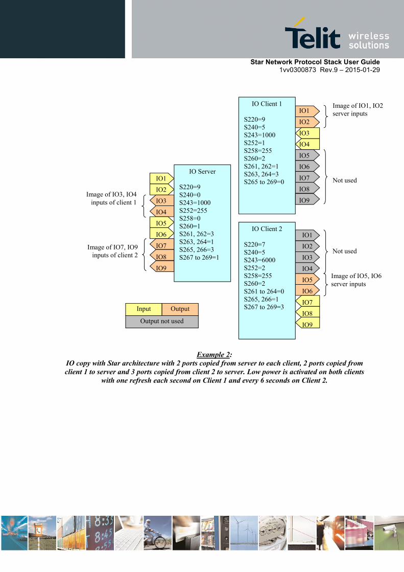
Star Network Protocol Stack User Guide 1vv0300873 Rev.9 – 2015-01-29
Reproduction forbidden without written authorization from Telit Communications S.p.A.- All Rights Reserved. Page 50 of 66
Example 2: IO copy with Star architecture with 2 ports copied from server to each client, 2 ports copied from client 1 to server and 3 ports copied from client 2 to server. Low power is activated on both clients
with one refresh each second on Client 1 and every 6 seconds on Client 2.
IO Client 1 S220=9 S240=5 S243=1000 S252=1 S258=255 S260=2 S261, 262=1 S263, 264=3 S265 to 269=0
IO Client 2 S220=7 S240=5 S243=6000 S252=2 S258=255 S260=2 S261 to 264=0 S265, 266=1 S267 to 269=3
Image of IO1, IO2 server inputs
Not used
Not used
Image of IO3, IO4 inputs of client 1
Image of IO7, IO9 inputs of client 2
Input Output
Output not used
IO1
IO2
IO3
IO4
IO5
IO6
IO7
IO8
IO9
Image of IO5, IO6 server inputs
IO1
IO2
IO3
IO4
IO5
IO6
IO7
IO8
IO9
IO Server S220=9 S240=0 S243=1000 S252=255 S258=0 S260=1 S261, 262=3 S263, 264=1 S265, 266=3 S267 to 269=1
IO1
IO2
IO3
IO4
IO5
IO6
IO7
IO8
IO9
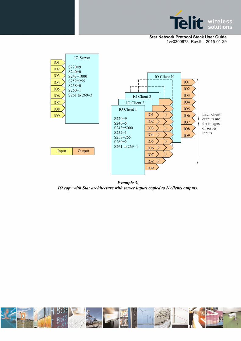
Star Network Protocol Stack User Guide 1vv0300873 Rev.9 – 2015-01-29
Reproduction forbidden without written authorization from Telit Communications S.p.A.- All Rights Reserved. Page 51 of 66
Example 3: IO copy with Star architecture with server inputs copied to N clients outputs.
IO Client N
IO Server S220=9 S240=0 S243=1000 S252=255 S258=0 S260=1 S261 to 269=3
Each client outputs are the images of server inputs
Input Output
IO Client 3
IO Client 2
IO Client 1 S220=9 S240=5 S243=5000 S252=1 S258=255 S260=2 S261 to 269=1
IO1
IO2
IO3
IO4
IO5
IO6
IO7
IO8
IO9
IO1
IO2
IO3
IO4
IO5
IO6
IO7
IO8
IO9
IO1
IO2
IO3
IO4
IO5
IO6
IO7
IO8
IO9
Star Network Protocol Stack User Guide 1vv0300873 Rev.9 – 2015-01-29
Reproduction forbidden without written authorization from Telit Communications S.p.A.- All Rights Reserved. Page 52 of 66
3.3.2. Optimized Usage
If refresh time is critical to update outputs of the server according to the inputs of a client, it is possible to use the interrupt functionality. In this case, an edge occurring on the client input will immediately trigger the transmission of an update frame to the server without waiting the next refresh period.
Finally, it is possible to detect a link failure in a small network with up to 9 clients. When a client sends its inputs values, the frame also contains the timer period expressed in seconds. The server records this period for each of the first 9 clients. When no messages are received from a client during twice the specified period + 1 second, the master indicates the failure writing ‘255TDE<CR>’ on its serial link and rising edge on ACK_TX signal.
Combining the two previous functionalities:
The consumption is very low,
The server outputs are refreshed immediately in case of an edge occurring on a client,
The radio link and client operation are checked periodically.
This configuration is ideal for wireless alarm sensor as explained in example 4.
Moreover, if it is not necessary to know on which client the edge occurred, it is possible to install up to 9 clients, all with IO4 as interrupt input activated. In this case, the IO4 server output will be set as soon as an event occurs on one of the 9 clients.
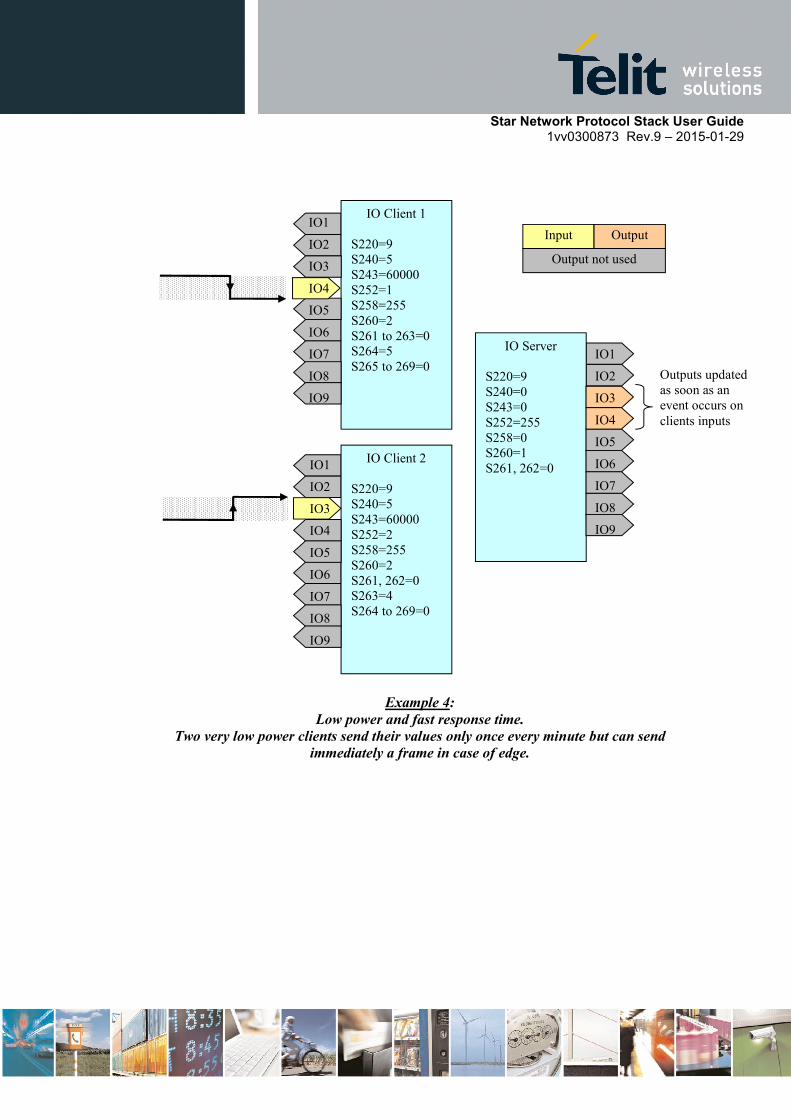
Star Network Protocol Stack User Guide 1vv0300873 Rev.9 – 2015-01-29
Reproduction forbidden without written authorization from Telit Communications S.p.A.- All Rights Reserved. Page 53 of 66
Example 4: Low power and fast response time.
Two very low power clients send their values only once every minute but can send immediately a frame in case of edge.
IO Client 1 S220=9 S240=5 S243=60000 S252=1 S258=255 S260=2 S261 to 263=0 S264=5 S265 to 269=0
IO Server S220=9 S240=0 S243=0 S252=255 S258=0 S260=1 S261, 262=0
IO Client 2 S220=9 S240=5 S243=60000 S252=2 S258=255 S260=2 S261, 262=0 S263=4 S264 to 269=0
Outputs updated as soon as an event occurs on clients inputs
Input Output
Output not used
IO1
IO2
IO3
IO4
IO5
IO6
IO7
IO8
IO9
IO1
IO2
IO3
IO4
IO5
IO6
IO7
IO8
IO9
IO1
IO2
IO3
IO4
IO5
IO6
IO7
IO8
IO9
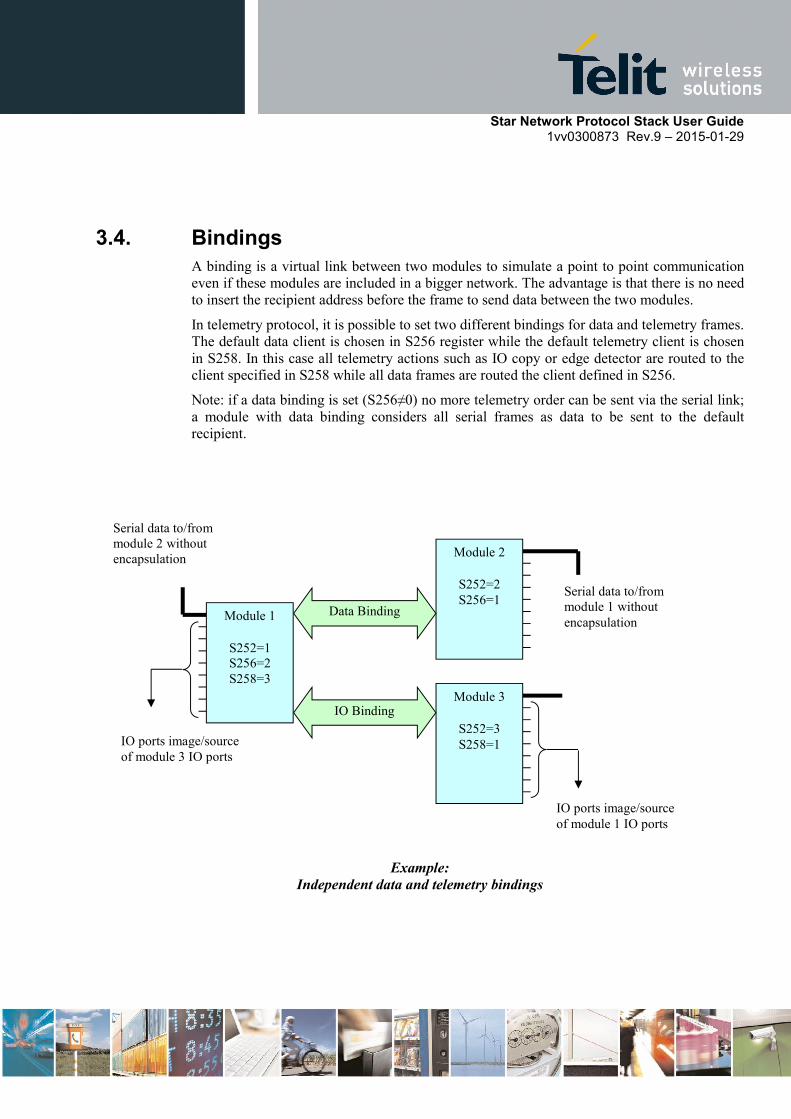
Star Network Protocol Stack User Guide 1vv0300873 Rev.9 – 2015-01-29
Reproduction forbidden without written authorization from Telit Communications S.p.A.- All Rights Reserved. Page 54 of 66
3.4. Bindings A binding is a virtual link between two modules to simulate a point to point communication even if these modules are included in a bigger network. The advantage is that there is no need to insert the recipient address before the frame to send data between the two modules.
In telemetry protocol, it is possible to set two different bindings for data and telemetry frames. The default data client is chosen in S256 register while the default telemetry client is chosen in S258. In this case all telemetry actions such as IO copy or edge detector are routed to the client specified in S258 while all data frames are routed the client defined in S256.
Note: if a data binding is set (S256≠0) no more telemetry order can be sent via the serial link; a module with data binding considers all serial frames as data to be sent to the default recipient.
Example:
Independent data and telemetry bindings
Module 1
S252=1 S256=2 S258=3
Module 2
S252=2 S256=1
Module 3
S252=3 S258=1
Serial data to/from module 2 without encapsulation
IO ports image/source of module 3 IO ports
Serial data to/from module 1 without encapsulation
IO ports image/source of module 1 IO ports
IO Binding
Data Binding
Star Network Protocol Stack User Guide 1vv0300873 Rev.9 – 2015-01-29
Reproduction forbidden without written authorization from Telit Communications S.p.A.- All Rights Reserved. Page 55 of 66
4. Smart Repeater
Smart Repeater is an operating mode of the S-One firmware similar to Addressed Secured mode; this operating mode is available only on LE70-868. With the smart repeater functionality it is possible to create a multi-hop network containing a central element (coordinator) and multiple nodes. The coordinator can communicate with nodes outside its direct radio coverage by using intermediate nodes in the network.
The Smart Repeater network is organized in branches and optionally sub-branches. A branch is a sequence of nodes starting from the coordinator, while a sub-branch is a sequence of nodes starting from a non-coordinator node; two contiguous elements in a branch or sub-branch are in direct radio coverage of each other.
In Smart Repeater mode, it is possible:
- to send frames from the coordinator to any node in the network
- to send frames from the coordinator in broadcast to all modules on a branch and sub
branches
- to send frames from the coordinator in broadcast to all sub branches of a particular
node
- to send frames from any node to the coordinator
- to send frames from any network element to itself
Sending a frame from a node to another one that is not the coordinator is not permitted.
Each node is assigned a position in the network which determines the path followed by frames exchanged when communicating with the coordinator. The configuration registers related to the Smart Repeater mode are described in Section 2.3.6. In case of a node failure which prevents a frame exchange between two contiguous elements in a branch, the Smart Repeater protocol supports network redundancy if there is direct radio coverage with the node immediately following the faulty node in the path toward the frame destination.
The picture below illustrates an example of a Smart Repeater network, with the setting of configuration registers for each network element.
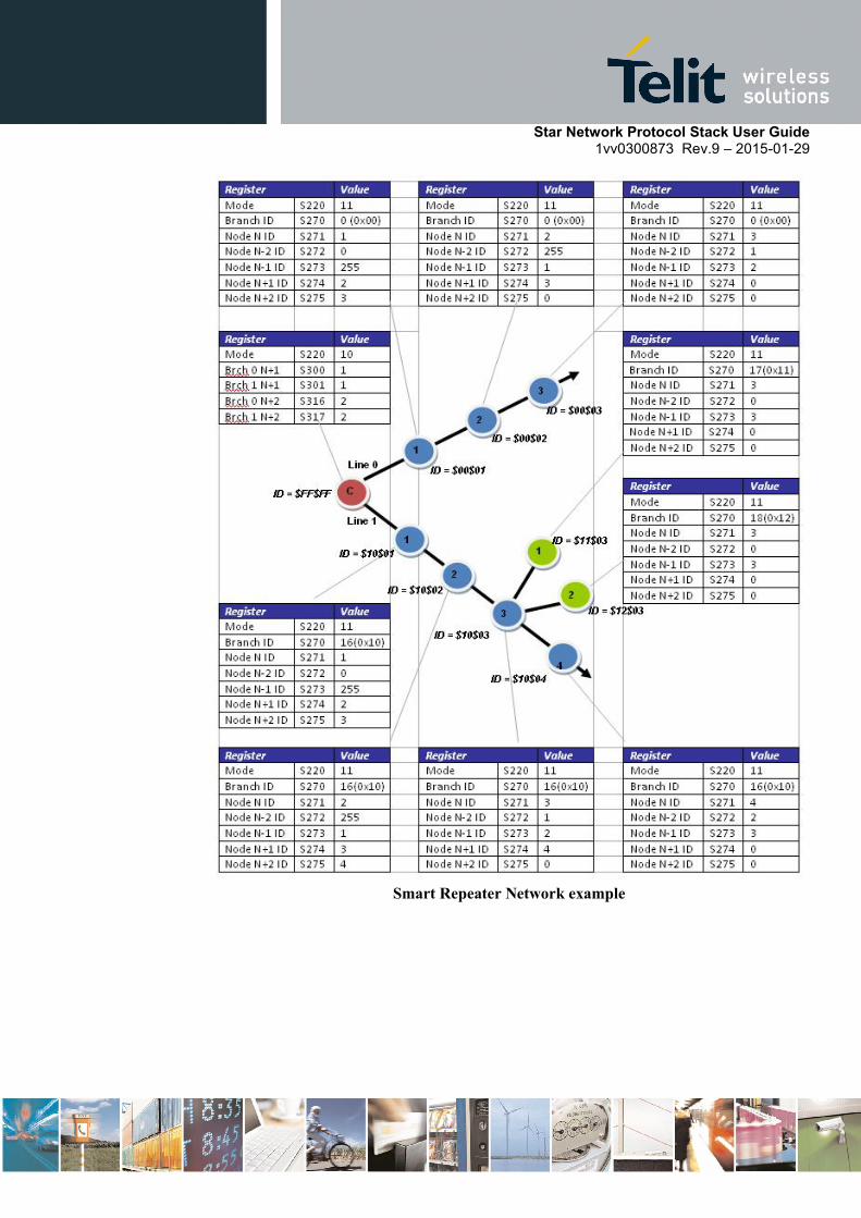
Star Network Protocol Stack User Guide 1vv0300873 Rev.9 – 2015-01-29
Reproduction forbidden without written authorization from Telit Communications S.p.A.- All Rights Reserved. Page 56 of 66
Smart Repeater Network example
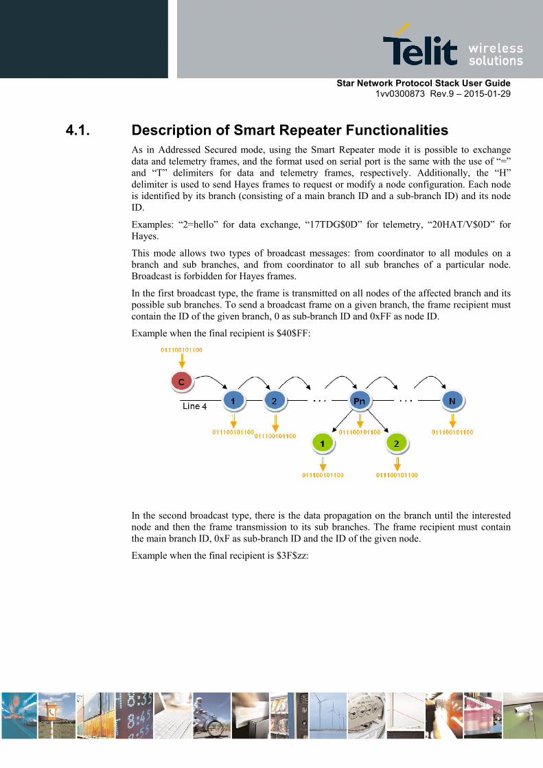
Star Network Protocol Stack User Guide 1vv0300873 Rev.9 – 2015-01-29
Reproduction forbidden without written authorization from Telit Communications S.p.A.- All Rights Reserved. Page 57 of 66
4.1. Description of Smart Repeater Functionalities As in Addressed Secured mode, using the Smart Repeater mode it is possible to exchange data and telemetry frames, and the format used on serial port is the same with the use of “=” and “T” delimiters for data and telemetry frames, respectively. Additionally, the “H” delimiter is used to send Hayes frames to request or modify a node configuration. Each node is identified by its branch (consisting of a main branch ID and a sub-branch ID) and its node ID.
Examples: “2=hello” for data exchange, “17TDG$0D” for telemetry, “20HAT/V$0D” for Hayes.
This mode allows two types of broadcast messages: from coordinator to all modules on a branch and sub branches, and from coordinator to all sub branches of a particular node. Broadcast is forbidden for Hayes frames.
In the first broadcast type, the frame is transmitted on all nodes of the affected branch and its possible sub branches. To send a broadcast frame on a given branch, the frame recipient must contain the ID of the given branch, 0 as sub-branch ID and 0xFF as node ID.
Example when the final recipient is $40$FF:
In the second broadcast type, there is the data propagation on the branch until the interested node and then the frame transmission to its sub branches. The frame recipient must contain the main branch ID, 0xF as sub-branch ID and the ID of the given node.
Example when the final recipient is $3F$zz:
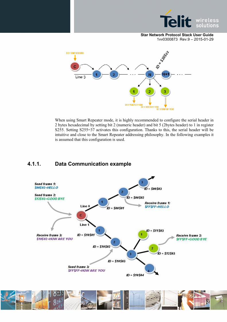
Star Network Protocol Stack User Guide 1vv0300873 Rev.9 – 2015-01-29
Reproduction forbidden without written authorization from Telit Communications S.p.A.- All Rights Reserved. Page 58 of 66
When using Smart Repeater mode, it is highly recommended to configure the serial header in 2 bytes hexadecimal by setting bit 2 (numeric header) and bit 5 (2bytes header) to 1 in register S255. Setting S255=37 activates this configuration. Thanks to this, the serial header will be intuitive and close to the Smart Repeater addressing philosophy. In the following examples it is assumed that this configuration is used.
4.1.1. Data Communication example
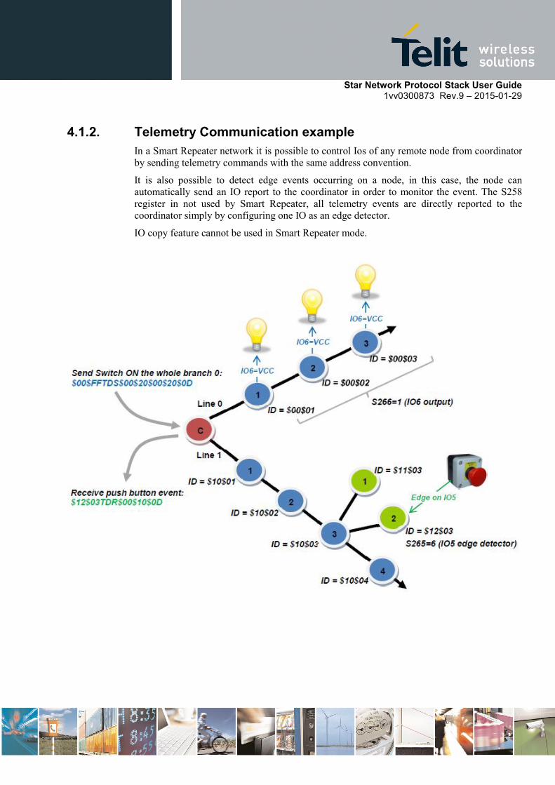
Star Network Protocol Stack User Guide 1vv0300873 Rev.9 – 2015-01-29
Reproduction forbidden without written authorization from Telit Communications S.p.A.- All Rights Reserved. Page 59 of 66
4.1.2. Telemetry Communication example
In a Smart Repeater network it is possible to control Ios of any remote node from coordinator by sending telemetry commands with the same address convention.
It is also possible to detect edge events occurring on a node, in this case, the node can automatically send an IO report to the coordinator in order to monitor the event. The S258 register in not used by Smart Repeater, all telemetry events are directly reported to the coordinator simply by configuring one IO as an edge detector.
IO copy feature cannot be used in Smart Repeater mode.
Star Network Protocol Stack User Guide 1vv0300873 Rev.9 – 2015-01-29
Reproduction forbidden without written authorization from Telit Communications S.p.A.- All Rights Reserved. Page 60 of 66
4.1.3. Hayes Communication example
Hayes commands can be sent over a Smart Repeater network. This allows reading or writing any register in a remote node located anywhere in the network. To use Hayes over Smart repeater network, the user serial frame should be composed by the destination address, the Hayes delimiter “H” and finally the desired Hayes command. As an example, “24HATS210?$0D” is the serial frame to check register S210 current value on module 24, this will trigger a response like “24HS210=5$0D”.
When using Hayes over a Smart repeater network, a few particularities should be considered:
- “ATR” command to reset all parameters to default is not allowed through the network
otherwise the remote module would lose its network configuration and would not be
reachable anymore.
“AT/S” command to check the whole registers list is not permitted due to the big size
of the response.
Broadcast of Hayes command from coordinator is not enabled because this could
trigger a big number of responses at the same time.
- “ATT0” and “ATT1” can be sent by the network to start continuous radio TX for test.
However the radio test is automatically stopped after 20 seconds.
- “+++” command can be sent through the network and an “OK” is received back but
this command has no effect on the remote module. The module stays in Smart repeater
operating mode. Only “+++” sent locally on serial port can make the module entering
in Hayes mode.
- Write access to smart repeater dedicated registers (range S270 to S331) is possible over
the network but the new values are only stored in EEPROM. The new setting is applied
only after sending an “ATO” command. This allows sending (and checking) a new
network configuration while using the current configuration until “ATO”. The
recommended practice is to write all the new values of smart repeater registers, check
them, change them if needed and finally when the new configuration is verified an
“ATO” command can be sent to apply it.
- “ATO” command sent in Smart Repeater mode is used to apply any new network
configuration.
- “S200” register can be written to change the channel of a remote module. In this case
the “OK” reply is sent first and then the new channel is applied. To change the radio
channel of a whole branch, start by the last module, ensure the “OK” response has been
received and repeat the operation for each module up to the Coordinator.
- “ATBL” is available also in Smart Repeater mode and has the effect of making the
remote module enter bootloader mode.
Star Network Protocol Stack User Guide 1vv0300873 Rev.9 – 2015-01-29
Reproduction forbidden without written authorization from Telit Communications S.p.A.- All Rights Reserved. Page 61 of 66
4.2. Acknowledgments By default, Smart Repeater uses both serial and radio acknowledges that can be disabled by setting bit 4 (RET) and bit 6 (ACK) respectively in register S255.
Radio Acknowledge increases the reliability of wireless communication. When a module sends a frame, the receiver sends back an ACK frame to confirm that the message is correctly received without error. If the sender does not receive any ACK after a wait delay, it can retry to send again the same message. The sender will retry as many times as defined in register S223. If not disabled in register S255, Smart Repeater systematically uses the ACK/Retry mechanism for each hop when routing messages along a branch, even in broadcast. Only the sub branches do not send radio ACK when receiving a broadcast message because of collision risks. However messages sent in unicast to a particular sub branch are acknowledged. This feature gives a good probability to reach the destination. However Smart Repeater uses radio ACK only at single hop level and does not provide a complete path acknowledgement, this is left to the user application responsibility if needed.
Serial Acknowledge gives to the user an indication that the sent message is correctly accepted or not by the network. Receiving an “OK” on the serial port confirms that the sent message is correctly formatted, has a correct destination address and has successfully passed the first hop to the destination. Please note that receiving “OK” does not guarantee that the message has reached the destination. The Smart Repeater mode does not offer this verification; if needed, it has to be implemented by the user in his application. Receiving an “ERROR” indicates that the message format is not correct, or the destination ID is not accepted, or communication on the first hop has failed.
Star Network Protocol Stack User Guide 1vv0300873 Rev.9 – 2015-01-29
Reproduction forbidden without written authorization from Telit Communications S.p.A.- All Rights Reserved. Page 62 of 66
5. LT70
The LT70 is a terminal equipped with a module LE70-868. It supports all the functionalities of traditional S-One except Telemetry. It adds a new S215 register to select the type of serial link used, configurable to work in any of the 4 following modes:
RS232 (S215=0, default value): This is the standard full duplex serial link. It works on up to 5 signals (3 without flow control): RxD, TxD, RTS, CTS and GND, and uses +/-12V levels. It is the only serial link type allowing flow control.
RS422 (S215=1): Full duplex link on 4 wires using voltage difference.
RS485 (S215=2): Half duplex link on 2 wires using voltage difference.
RS485-Full (S215=3: Full duplex link on 4 wires using voltage difference. Unlike the point-to-point RS422 protocol, it can be used for multipoint operations.
ATR command doesn’t reset this register to its default value.
Star Network Protocol Stack User Guide 1vv0300873 Rev.9 – 2015-01-29
Reproduction forbidden without written authorization from Telit Communications S.p.A.- All Rights Reserved. Page 63 of 66
6. LE51-868 S
LE51S is a module that supports all the functionalities of traditional S-One. It is able to work in transparent mode, addressed and secure mode, and as smart repeater. The LE51-868 S adds to the Star Network Protocol Telit technology the possibility to use SIGFOX long-range technology. For further information, please refer to [8].
Star Network Protocol Stack User Guide 1vv0300873 Rev.9 – 2015-01-29
Reproduction forbidden without written authorization from Telit Communications S.p.A.- All Rights Reserved. Page 64 of 66
7. Document History
RReevviissiioonn DDaattee CChhaannggeess 0 2011-02-23 First issue 1 2011-05-17 §II.2 – Operating Modes: complete rewrite to be clearer.
§II.3 – Network Configuration : addition of AES bit and explanation of this bit in 255 register
§II.3 – Default telemetry Address: S258, new register coming with new telemetry functions now available
§II.3 – Low Power Configuration: this chapter is completely new and describe all low power modes and associate registers.
§II.4 : Note about Wake on Radio limitation now removed because Wake on Radio is now operational in all modes.
§II.4 : in registers table, add AES bit in reg 255 and add reg 258.
§II.4 : in registers table, S260 appeared with new telemetry features, and some precisions for reg S261 to 269.
§II.4 : in registers table, new register for AES Encryption Key
§II.5. Dedicated IO description : this chapter is completely new and describes all pins which have specific functions
§III.1 : add IRQ feature, add I/O copy features. §III.1 : new version of the IO table, clearer and more
exhaustive. §III.2 – Analog Get request : this paragraph is new. §III.2 – Interruptible inputs, IO copy and Binding : new
paragraphs coming with new telemetry functionalities. 2 2011-10-25 §3.1 – better description of I/O3 and I/O4 features
§2.2 – Information regarding buffer size §2.3 – Information regarding buffer capacity for serial
flow control
3 2011-11-17 Template modification
4 2012-07-02 §2.3 : registers modifications including LE50-433 §2.4 : registers modifications including LE50-433
5 2012-08-29 §2.6 – Hayes over the air : this paragraph is new
6 2013-05-17 §2.3.5 : update of S243 Register description §2.4 : addition of new Telemetry Client mode in S260;
update of S243 Register
Star Network Protocol Stack User Guide 1vv0300873 Rev.9 – 2015-01-29
Reproduction forbidden without written authorization from Telit Communications S.p.A.- All Rights Reserved. Page 65 of 66
§3.2.4 – new Section for Telemetry Client Addition of Smart Repeater mode (updated § 2.2, § 2.3.3,
§ 2.3.4 and § 2.4, added § 2.3.6 and Chapter 4) Updated description of frame size limitations in cyclic
wakeup mode (§2.3.5) Addition of LE70-868 Addition at 915 MHz operation to LE50-868 Addition of S211 configuration register § 2.3.1: Clarification of radio preamble setting for
acknowledge frames § 3.1: Removed limitations on edge detector
configurations able to wake up the module from stand-by Addition of syncword configuration register (S207) Changed LE50-433 software version to GD.S00.01.04 § 2.4: S223 register: deleted clause “255 means retry
until success” 7 2013-11-08 Updated applicability table (product and SW version)
§2.3.2: Updated section and added “Serial Link Type” S215 register and its description (available only in LT70-868 Terminal).
§2.4: added S215 register in Public Register List table §3: added warning in telemetry usage Added chapter 5 “LT70”
8 2014-05-13 § 2.3.2: addition of 300 bps serial baud rate in S210 register and corresponding minimum serial timeout in S214 register.(available only for LE50-868)
§ 2.4: modified S210 register section to support 300bps serial speed (available only for LE50-868); modified maximum value in S214 register from 100 to 255 ms.
Changed LE50-868 software version to GC.S00.01.05 § 2.3.1: modified S200 radio channel register paragraph. § 2.3.2: deleted clause “(only for LE50-868)”and added
clause “not available for LE50-433”. § 2.4: deleted clause “(only for LE50-868)”and added
clause “(not available for LE50-433)”. § 2.4: modified S202 register section to support 7 and 10
dBm output power levels (for LE70-868). Changed LE70-868 software version to GJ.S00.02.04 §2.3.1: changed radio channel register (S200) table. §2.3.5: Added new configurable bits in S240 register. §3.3.3: Added S228 (“Hayes over the air”) register. §3.4: Added S228 and S296 (“AES Key Read”) registers
and modified S240 register, in Public Register List table. §2.3.2: added warning for S215 register usage. §2.4: added clauses in S215 and S260 registers. §5. added precision in S215 register usage. §2.3.1: Added LE51-868 S radio configuration
Star Network Protocol Stack User Guide 1vv0300873 Rev.9 – 2015-01-29
Reproduction forbidden without written authorization from Telit Communications S.p.A.- All Rights Reserved. Page 66 of 66
§2.3.2: Added LE51-868 S as smart repeater §2.4: Added LE51-868 S register configurations Added §6
9 2015-01-29 Updated applicability table (SW version) §2.3.3: Modified S227 register: random waiting time is
not automatically activated when LBT is ON