Embed Size (px)
Citation preview
Designation: D 4814 – 07b An American National Standard
Standard Specification forAutomotive Spark-Ignition Engine Fuel1
This standard is issued under the fixed designation D 4814; the number immediately following the designation indicates the year oforiginal adoption or, in the case of revision, the year of last revision. A number in parentheses indicates the year of last reapproval. Asuperscript epsilon (e) indicates an editorial change since the last revision or reapproval.
This standard has been approved for use by agencies of the Department of Defense.
1. Scope*
1.1 This specification covers the establishment of require-ments of automotive fuels for ground vehicles equipped withspark-ignition engines.
1.2 This specification describes various characteristics ofautomotive fuels for use over a wide range of operatingconditions. It provides for a variation of the volatility and watertolerance of automotive fuel in accordance with seasonalclimatic changes at the locality where the fuel is used. For theperiod May 1 through Sept. 15, the maximum vapor pressurelimits issued by the U.S. Environmental Protection Agency(EPA) are specified for each geographical area except Alaskaand Hawaii. Variation of the antiknock index with seasonalclimatic changes and altitude is discussed in Appendix X1.This specification neither necessarily includes all types of fuelsthat are satisfactory for automotive vehicles, nor necessarilyexcludes fuels that can perform unsatisfactorily under certainoperating conditions or in certain equipment. The significanceof each of the properties of this specification is shown inAppendix X1.
1.3 The spark-ignition engine fuels covered in this specifi-cation are gasoline and its blends with oxygenates, such asalcohols and ethers. This specification does not apply to fuelsthat contain an oxygenate as the primary component, such asFuel Methanol (M85). The concentrations and types of oxy-genates are not specifically limited in this specification. How-ever, depending on oxygenate type, as oxygenate contentincreases above some threshold level, the likelihood for vehicleproblems also increases. The composition of both unleaded andleaded fuel is limited by economic, legal, and technicalconsideration, but their properties, including volatility, aredefined by this specification. In addition, the composition ofunleaded fuel is subject to the rules, regulations, and Clean AirAct waivers of the U.S. Environmental Protection Agency(EPA). With regard to fuel properties, including volatility, thisspecification can be more or less restrictive than the EPA rules,regulations, and waivers. Refer to Appendix X3 for discussions
of EPA rules relating to fuel volatility, lead and phosphorouscontents, deposit control additive certification, and use ofoxygenates in blends with unleaded gasoline. Contact the EPAfor the latest versions of the rules and additional requirements.
1.4 This specification does not address the emission char-acteristics of reformulated spark-ignition engine fuel. Refor-mulated spark-ignition engine fuel is required in some areas tolower emissions from automotive vehicles, and its character-istics are described in the research report on reformulatedspark-ignition engine fuel.2 However, in addition to the legalrequirements found in this research report, reformulated spark-ignition engine fuel should meet the performance requirementsfound in this specification.
1.5 This specification represents a description of automotivefuel as of the date of publication. The specification is undercontinuous review, which can result in revisions based onchanges in fuel, automotive requirements, or test methods, or acombination thereof. All users of this specification, therefore,should refer to the latest edition.
NOTE 1—If there is any doubt as to the latest edition of SpecificationD 4814, contact ASTM International Headquarters.
1.6 Tests applicable to gasoline are not necessarily appli-cable to its blends with oxygenates. Consequently, the type offuel under consideration must first be identified in order toselect applicable tests. Test Method D 4815 provides a proce-dure for determining oxygenate concentration in mass percent.Test Method D 4815 also includes procedures for calculatingmass oxygen content and oxygenate concentration in volumepercent. Appendix X4 provides a procedure for calculating themass oxygen content of a fuel using measured oxygenate type,oxygenate concentration in volume percent, and measureddensity or relative density of the fuel.
1.7 The following applies to all specified limits in thisstandard: For purposes of determining conformance with thesespecifications, an observed value or a calculated value shall berounded “to the nearest unit” in the right-most significant digitused in expressing the specification limit, in accordance withthe rounding method of Practice E 29. For a specification limitexpressed as an integer, a trailing zero is significant only if the
1 This specification is under the jurisdiction of ASTM Committee D02 onPetroleum Products and Lubricants and is the direct responsibility of SubcommitteeD02.A0.01 on Gasoline and Gasoline-Oxygenate Blends.
Current edition approved Dec. 1, 2007. Published January 2008. Originallyapproved in 1988. Last previous edition approved in 2007 as D 4814–07a.
2 Supporting data have been filed at ASTM International Headquarters and maybe obtained by requesting Research Report RR:D02-1347.
1
*A Summary of Changes section appears at the end of this standard.
Copyright © ASTM International, 100 Barr Harbor Drive, PO Box C700, West Conshohocken, PA 19428-2959, United States.
Copyright ASTM International, 100 Barr Harbor Drive, West Conshohocken, Pennsylvania 19428, USADistributed under ASTM license agreement by Shanghai Institute of Standardization(SIS) Tel:86-21-64370807
ASTM International 版权所有, 100 Barr Harbor Drive, West Conshohocken, Pennsylvania, 19428, USA由上海市标准化研究院(SIS)根据ASTM授权协议进行销售 地址:上海市长乐路1219/1227号 邮编:200031 联系电话:86-21-64370807
decimal point is specified. For a specified limit expressed as aninteger, and the right-most digit is non-zero, the right-mostdigit is significant without a decimal point being specified. Thisconvention applies to specified limits in Tables 1, 3, and TableX8.1, and it will not be observed in the remainder of thisspecification.
1.8 The values stated in SI units are the standard, exceptwhen other units are specified by federal regulation. Valuesgiven in parentheses are provided for information only.
NOTE 2—Many of the values shown in Table 1 were originallydeveloped using U.S. customary units and were subsequently soft-converted to SI values. As a result, conversion of the SI values willsometimes differ slightly from the U.S. customary values shown becauseof round-off. In some cases, federal regulations specify non-SI units.
1.9 The following safety hazard caveat pertains only to thetest method portion, Annex A1, of this specification. Thisstandard does not purport to address all of the safety concerns,if any, associated with its use. It is the responsibility of the userof this standard to establish appropriate safety and healthpractices and determine the applicability of regulatory limita-tions prior to use.
2. Referenced Documents
2.1 ASTM Standards: 3
D 86 Test Method for Distillation of Petroleum Products atAtmospheric Pressure
D 130 Test Method for Corrosiveness to Copper fromPetroleum Products by Copper Strip Test
D 287 Test Method for API Gravity of Crude Petroleum andPetroleum Products (Hydrometer Method)
D 381 Test Method for Gum Content in Fuels by JetEvaporation
D 439 Specification for Automotive Gasoline4
D 525 Test Method for Oxidation Stability of Gasoline(Induction Period Method)
D 1266 Test Method for Sulfur in Petroleum Products(Lamp Method)
D 1298 Test Method for Density, Relative Density (SpecificGravity), or API Gravity of Crude Petroleum and LiquidPetroleum Products by Hydrometer Method
D 2622 Test Method for Sulfur in Petroleum Products byWavelength Dispersive X-ray Fluorescence Spectrometry
D 2699 Test Method for Research Octane Number ofSpark-Ignition Engine Fuel
D 2700 Test Method for Motor Octane Number of Spark-Ignition Engine Fuel
D 2885 Test Method for Determination of Octane Numberof Spark-Ignition Engine Fuels by On-Line Direct Com-parison Technique
D 3120 Test Method for Trace Quantities of Sulfur in LightLiquid Petroleum Hydrocarbons by Oxidative Microcou-lometry
D 3231 Test Method for Phosphorus in GasolineD 3237 Test Method for Lead in Gasoline by Atomic
Absorption SpectroscopyD 3341 Test Method for Lead in Gasoline—Iodine
Monochloride MethodD 4052 Test Method for Density and Relative Density of
Liquids by Digital Density MeterD 4057 Practice for Manual Sampling of Petroleum and
Petroleum ProductsD 4177 Practice for Automatic Sampling of Petroleum and
Petroleum ProductsD 4306 Practice for Aviation Fuel Sample Containers for
Tests Affected by Trace ContaminationD 4815 Test Method for Determination of MTBE, ETBE,
TAME, DIPE, tertiary-Amyl Alcohol and C1 to C4 Alco-hols in Gasoline by Gas Chromatography
D 4953 Test Method for Vapor Pressure of Gasoline andGasoline-Oxygenate Blends (Dry Method)
D 5059 Test Methods for Lead in Gasoline by X-RaySpectroscopy
3 For referenced ASTM standards, visit the ASTM website, www.astm.org, orcontact ASTM Customer Service at [email protected]. For Annual Book of ASTMStandards volume information, refer to the standard’s Document Summary page onthe ASTM website.
4 Withdrawn.
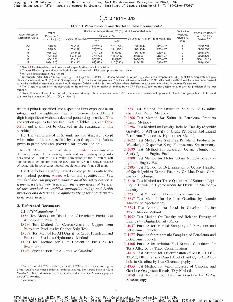
TABLE 1 Vapor Pressure and Distillation Class RequirementsA
Vapor Pressure/Distillation Class
VaporPressure,B
max, kPa (psi)
Distillation Temperatures, °C (°F), at % Evaporated. maxC DistillationResidue,
volume %,max
Driveability Index,D
max, °C (°F)DerivedE,F10 volume %, max
50 volume %90 volume %, max End Point, max
min max
AA 54(7.8) 70.(158) 77(170.) 121(250.) 190.(374) 225(437) 2 597(1250.)A 62(9.0) 70.(158) 77(170.) 121(250.) 190.(374) 225(437) 2 597(1250.)B 69(10.0) 65(149) 77(170.) 118(245) 190.(374) 225(437) 2 591(1240.)C 79(11.5) 60.(140.) 77(170.) 116(240.) 185(365) 225(437) 2 586(1230.)D 93(13.5) 55.(131) 66(150.) 113(235) 185(365) 225(437) 2 580.(1220.)E 103(15.0) 50.(122) 66(150.) 110.(230.) 185(365) 225(437) 2 569(1200.)
A See 1.7 for determining conformance with specification limits in this table.B Consult EPA for approved test methods for compliance with EPA vapor pressure regulations.C At 101.3 kPa pressure (760 mm Hg).D Driveability Index (DI) = 1.5 T10 + 3.0 T50 + 1.0 T90+ 1.33°C (2.4°F) 3 Ethanol Volume %, where T10 = distillation temperature, °C (°F), at 10 % evaporated, T 50 =
distillation temperature, °C (°F), at 50 % evaporated, T90 = distillation temperature, °C (°F), at 90 % evaporated, and 1.33 is the coefficient for the volume % ethanol presentwhen the distillation results are determined in degrees Celsius and 2.4 is the coefficient when distillation results are determined in degrees Fahrenheit.
E The DI specification limits are applicable at the refinery or import facility as defined by 40 CFR Part 80.2 and are not subject to correction for precision of the testmethod.
F Since DI is an index and has no units, the standard temperature conversion from U.S. customary to SI units is not appropriate. The following equation is to be usedto make the conversion: DI°C 5 ~DI°F – 176!/1.8
D 4814 – 07b
2
Copyright ASTM International, 100 Barr Harbor Drive, West Conshohocken, Pennsylvania 19428, USADistributed under ASTM license agreement by Shanghai Institute of Standardization(SIS) Tel:86-21-64370807
ASTM International 版权所有, 100 Barr Harbor Drive, West Conshohocken, Pennsylvania, 19428, USA由上海市标准化研究院(SIS)根据ASTM授权协议进行销售 地址:上海市长乐路1219/1227号 邮编:200031 联系电话:86-21-64370807
D 5188 Test Method for Vapor-Liquid Ratio TemperatureDetermination of Fuels (Evacuated Chamber Method)
D 5190 Test Method for Vapor Pressure of Petroleum Prod-ucts (Automatic Method)
D 5191 Test Method for Vapor Pressure of Petroleum Prod-ucts (Mini Method)
D 5453 Test Method for Determination of Total Sulfur inLight Hydrocarbons, Spark Ignition Engine Fuel, DieselEngine Fuel, and Engine Oil by Ultraviolet Fluorescence
D 5482 Test Method for Vapor Pressure of Petroleum Prod-ucts (Mini Method—Atmospheric)
D 5500 Test Method for Vehicle Evaluation of UnleadedAutomotive Spark-Ignition Engine Fuel for Intake ValveDeposit Formation
D 5598 Test Method for Evaluating Unleaded AutomotiveSpark-Ignition Engine Fuel for Electronic Port Fuel Injec-tor Fouling
D 5599 Test Method for Determination of Oxygenates inGasoline by Gas Chromatography and Oxygen SelectiveFlame Ionization Detection
D 5842 Practice for Sampling and Handling of Fuels forVolatility Measurement
D 5845 Test Method for Determination of MTBE, ETBE,TAME, DIPE, Methanol, Ethanol and tert-Butanol inGasoline by Infrared Spectroscopy
D 5854 Practice for Mixing and Handling of LiquidSamples of Petroleum and Petroleum Products
D 6469 Guide for Microbial Contamination in Fuels andFuel Systems
D 6920 Test Method for Total Sulfur in Naphthas, Distil-lates, Reformulated Gasolines, Diesels, Biodiesels, andMotor Fuels by Oxidative Combustion and Electrochemi-cal Detection
D 7039 Test Method for Sulfur in Gasoline and Diesel Fuelby Monochromatic Wavelength Dispersive X-ray Fluores-cence Spectrometry
E 29 Practice for Using Significant Digits in Test Data toDetermine Conformance with Specifications
2.2 Government Standard:CFR 40 Code of Federal Regulations5
2.3 Other Standard:CCR Title 17, §60100-§60114 California Code of Regula-
tions6
3. Terminology
3.1 Definitions:3.1.1 antiknock index, n—the arithmetic average of the
Research octane number (RON) and Motor octane number(MON), that is, (RON + MON)/2.
3.1.2 gasoline, n—a volatile mixture of liquid hydrocar-bons, generally containing small amounts of additives, suitablefor use as a fuel in spark-ignition, internal combustion engines.
3.1.3 gasoline-alcohol blend, n—a fuel consisting primarilyof gasoline along with a substantial amount (more than 0.35
mass % oxygen, or more than 0.15 mass % oxygen if methanolis the only oxygenate) of one or more alcohols.
3.1.4 gasoline-ether blend, n—a fuel consisting primarily ofgasoline along with a substantial amount (more than 0.35 mass% oxygen) of one or more ethers.
3.1.5 gasoline-oxygenate blend, n—a fuel consisting prima-rily of gasoline along with a substantial amount (more than0.35 mass % oxygen, or more than 0.15 mass % oxygen ifmethanol is the only oxygenate) of one or more oxygenates.
3.1.6 oxygenate, n—an oxygen-containing, ashless, organiccompound, such as an alcohol or ether, which can be used as afuel or fuel supplement.
3.1.7 refinery, n—a plant at which gasoline or diesel fuel isproduced.
3.1.7.1 Discussion—This definition is from CFR 40 Part80.2. In the federal definition, a plant not only covers theconventional refinery, but also covers oxygenate blending andother facilities where gasoline is produced.
3.2 Applicability—To determine when a fuel contains asubstantial amount of an oxygenate, a gasoline-oxygenateblend is defined as a fuel that contains more than 0.35 mass %oxygen, or more than 0.15 mass % oxygen if methanol is theonly oxygenate. The definitions in this section do not apply tofuels that contain an oxygenate as the primary component; forexample, fuel methanol (M85).
NOTE 3—The criteria in 3.2 were selected with consideration given tocurrent oxygenate levels in the marketplace, state labeling practices, andconsistency with federal legislation and regulations.
NOTE 4—Refer to Test Method D 4815 to calculate the mass oxygencontent of a fuel using oxygenate concentration in mass %. Refer toAppendix X4 to calculate mass oxygen content of a fuel using oxygenateconcentration in volume %.
4. Ordering Information
4.1 The purchasing agency shall:4.1.1 State the antiknock index as agreed upon with the
seller,4.1.2 Indicate the season and locality in which the fuel is to
be used,4.1.3 Indicate the lead level required (Table 2), and4.1.4 State the concentration and types of oxygenates
present as agreed upon with the seller.
5. Performance Requirements
5.1 Some requirements and test methods applicable toautomotive spark-ignition engine fuel depend on whether thefuel is a gasoline, or a gasoline-oxygenate blend. Test MethodsD 4815 and D 5599, gas chromatographic test methods, are therecommended procedures to detect the types and amounts ofoxygenates. Once the type of fuel is known, the appropriaterequirements and test methods can be identified by reference toTable 1, Table 3, and Section 7.
5.2 Volatility of fuels is varied for seasonal climatic changesand conformance to U.S. EPA volatility regulations by provid-ing six vapor pressure/distillation classes and six vapor lockprotection classes for fuel. Volatility of fuel is specified by analphanumeric designation that uses a letter from Table 1 and anumber from Table 3.
5 Available from U.S. Government Printing Office, Superintendent of Docu-ments, 732 N. Capitol St., NW, Mail Stop: SDE, Washington, DC 20401.
6 Available from Barclays, 50 California Street, San Francisco, CA 94111.
D 4814 – 07b
3
Copyright ASTM International, 100 Barr Harbor Drive, West Conshohocken, Pennsylvania 19428, USADistributed under ASTM license agreement by Shanghai Institute of Standardization(SIS) Tel:86-21-64370807
ASTM International 版权所有, 100 Barr Harbor Drive, West Conshohocken, Pennsylvania, 19428, USA由上海市标准化研究院(SIS)根据ASTM授权协议进行销售 地址:上海市长乐路1219/1227号 邮编:200031 联系电话:86-21-64370807
5.2.1 The seasonal and geographic distribution of the com-bined vapor pressure/distillation-vapor lock classes is shown inTable 4. Tables 5-7 show the federal ozone nonattainment areasat several vapor lock protection levels that require reducedvapor pressure in the summertime. Tables 8-11 show at severalvapor lock protection levels the areas that require federalreformulated spark-ignition engine fuel in the summertime.Table 12 shows the areas with restrictive local vapor pressurelimits that have been approved under the EPA state implemen-tation plan (SIP).
5.2.2 The EPA vapor pressure regulations can cause thedistillation of the fuel to be less volatile, which for somevehicles, results in a worse warm-up driveability performance.
5.2.3 Driveability Index (DI) is intended to provide controlof distillation parameters and ethanol content that influencecold start and warm-up driveability. It is a function of the 10 %,50 %, and 90 % evaporated distillation temperatures measuredby Test Method D 86 and the ethanol content measured by thetest methods shown in 7.1.9.
5.2.4 Test Method D 5188 is the method for determiningvapor-liquid ratio temperatures by an evacuated chambermethod for gasoline-oxygenate blends, as well as for gasoline.The methods for estimating temperature-V/L (see AppendixX2) are only applicable for gasoline.
5.3 Antiknock index (AKI) is very important to engineperformance. The matching of engine octane requirement tofuel octane level (AKI) is critical to the durability andperformance of engines; this cannot be accomplished with asingle specified minimum level of antiknock index. AppendixX1 includes a discussion of antiknock indexes of fuels cur-rently marketed and relates these levels to the octane needs of
broad groups of engines and vehicles. Also discussed is theeffect of altitude and weather on vehicle antiknock require-ments.
5.4 Additional fuel requirements are shown in Table 2.5.5 The properties of gasoline-oxygenate blends can differ
considerably from those of gasoline. Consequently, additionalrequirements are needed for gasoline-oxygenate blends. Theserequirements involve evaluation of compatibility with plasticand elastomeric materials in fuel systems, corrosion of metals,and especially in the case of gasoline-alcohol blends, watertolerance. Requirements for metal corrosion (other than cop-per) and material compatibility are not given because testmethods and appropriate limits are still under development.When these have been developed, they will be included in thisspecification.
5.6 Depending on oxygenate type and concentration in theblend, vehicle driveability with gasoline-oxygenate blends candiffer significantly from that with gasolines having similarvolatility characteristics.
5.7 Water Tolerance:5.7.1 The term water tolerance is used to indicate the ability
of a gasoline-oxygenate blend to dissolve water without phaseseparation. This may not be a problem with gasoline-etherblends, but it is of primary concern for alcohol-containingblends, as blends of gasoline with low-molecular weightalcohols generally will dissolve about 0.1 to 0.7 mass % ofwater under normal conditions, depending on the nature andamount of the alcohol(s) used, the specific hydrocarbonspresent, and the temperature of the blend. Additional informa-tion on water tolerance is provided in Appendix X8.
5.8 Deposit control additives are added to fuel to help keepcarburetors, fuel injectors, and intake valves clean. Depositcontrol additives are required to be certified by the EPA assummarized in X3.5. Each additive is certified for use at alowest additive concentration (LAC), which is the lowest levelcertified to be effective in preventing deposit formation. Allparties who blend deposit control additives into fuel mustcomplete mandatory volume additive reconciliation (VAR)accounting to establish that the product was additized at aconcentration that was at least equal to the LAC.
TABLE 2 Detailed Requirements for all Volatility ClassesA
Lead Content, max, g/L (g/U.S. gal)B Copper StripCorrosion,
max
Silver StripCorrosion,C
max
Solvent-washedGum Content,
mg/100 mL, max
Sulfur, max, mass % Oxidation Stability,Minimum,minutesUnleaded Leaded Unleaded Leaded
0.013(0.05) 1.1(4.2) No. 1 1 5 0.0080D 0.15 240.A See Appendix X1 for information on Antiknock Index.B See Appendix X3 for U.S. EPA maximum limits for lead and phosphorus contents in unleaded gasoline (X3.2.1) and maximum average lead limits for leaded gasoline
(X3.2.2).C See Annex A1 for information regarding the test method.D Qualified small refineries have varying maximum sulfur limits up to 0.0450 mass % which are based on their 1997-1998 sulfur level baseline. For Geographical
Phase-In Area (GPA) and qualified small refineries producing 15 ppm maximum sulfur content diesel fuel beginning in 2006, the 2006 gasoline sulfur limits are extendedthrough 2008 for GPA refineries (0.0300 mass % cap) and through 2010 for qualified small refineries (up to 0.0450 mass % cap). If values are found in excess of 0.0080mass %, it is the supplier’s responsibility to provide proof that the source was a qualified refinery. EPA provides 0.0015 mass % and 0.0026 mass % reproducibilities fordownstream compliance for maximum limits of 0.0080 mass % and 0.0300 mass %, respectively.
TABLE 3 Vapor Lock Protection Class RequirementsA
Vapor LockProtection Class
Temperature, °C (°F) for aVapor-Liquid Ratio of 20, min
1 60.(140.)2 56(133)3 51(124)4 47(116)5 41(105)6 35(95)
A See 1.7 for determining conformance with specification limits in this table.
D 4814 – 07b
4
Copyright ASTM International, 100 Barr Harbor Drive, West Conshohocken, Pennsylvania 19428, USADistributed under ASTM license agreement by Shanghai Institute of Standardization(SIS) Tel:86-21-64370807
ASTM International 版权所有, 100 Barr Harbor Drive, West Conshohocken, Pennsylvania, 19428, USA由上海市标准化研究院(SIS)根据ASTM授权协议进行销售 地址:上海市长乐路1219/1227号 邮编:200031 联系电话:86-21-64370807
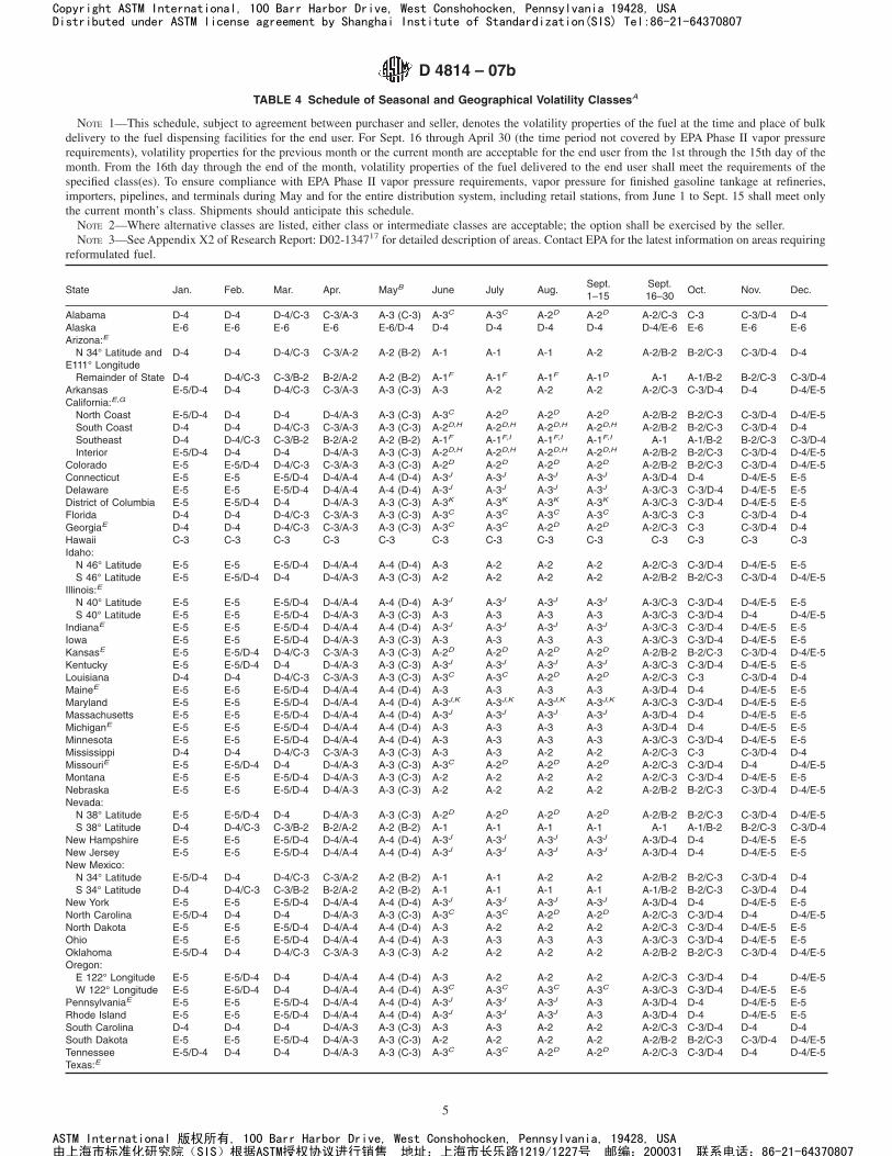
TABLE 4 Schedule of Seasonal and Geographical Volatility ClassesA
NOTE 1—This schedule, subject to agreement between purchaser and seller, denotes the volatility properties of the fuel at the time and place of bulkdelivery to the fuel dispensing facilities for the end user. For Sept. 16 through April 30 (the time period not covered by EPA Phase II vapor pressurerequirements), volatility properties for the previous month or the current month are acceptable for the end user from the 1st through the 15th day of themonth. From the 16th day through the end of the month, volatility properties of the fuel delivered to the end user shall meet the requirements of thespecified class(es). To ensure compliance with EPA Phase II vapor pressure requirements, vapor pressure for finished gasoline tankage at refineries,importers, pipelines, and terminals during May and for the entire distribution system, including retail stations, from June 1 to Sept. 15 shall meet onlythe current month’s class. Shipments should anticipate this schedule.
NOTE 2—Where alternative classes are listed, either class or intermediate classes are acceptable; the option shall be exercised by the seller.NOTE 3—See Appendix X2 of Research Report: D02-134717 for detailed description of areas. Contact EPA for the latest information on areas requiring
reformulated fuel.
State Jan. Feb. Mar. Apr. MayB June July Aug.Sept.1–15
Sept.16–30
Oct. Nov. Dec.
Alabama D-4 D-4 D-4/C-3 C-3/A-3 A-3 (C-3) A-3C A-3C A-2D A-2D A-2/C-3 C-3 C-3/D-4 D-4Alaska E-6 E-6 E-6 E-6 E-6/D-4 D-4 D-4 D-4 D-4 D-4/E-6 E-6 E-6 E-6Arizona:E
N 34° Latitude andE111° Longitude
D-4 D-4 D-4/C-3 C-3/A-2 A-2 (B-2) A-1 A-1 A-1 A-2 A-2/B-2 B-2/C-3 C-3/D-4 D-4
Remainder of State D-4 D-4/C-3 C-3/B-2 B-2/A-2 A-2 (B-2) A-1F A-1F A-1F A-1D A-1 A-1/B-2 B-2/C-3 C-3/D-4Arkansas E-5/D-4 D-4 D-4/C-3 C-3/A-3 A-3 (C-3) A-3 A-2 A-2 A-2 A-2/C-3 C-3/D-4 D-4 D-4/E-5California:E,G
North Coast E-5/D-4 D-4 D-4 D-4/A-3 A-3 (C-3) A-3C A-2D A-2D A-2D A-2/B-2 B-2/C-3 C-3/D-4 D-4/E-5South Coast D-4 D-4 D-4/C-3 C-3/A-3 A-3 (C-3) A-2D,H A-2D,H A-2D,H A-2D,H A-2/B-2 B-2/C-3 C-3/D-4 D-4Southeast D-4 D-4/C-3 C-3/B-2 B-2/A-2 A-2 (B-2) A-1F A-1F,I A-1F,I A-1F,I A-1 A-1/B-2 B-2/C-3 C-3/D-4Interior E-5/D-4 D-4 D-4 D-4/A-3 A-3 (C-3) A-2D,H A-2D,H A-2D,H A-2D,H A-2/B-2 B-2/C-3 C-3/D-4 D-4/E-5
Colorado E-5 E-5/D-4 D-4/C-3 C-3/A-3 A-3 (C-3) A-2D A-2D A-2D A-2D A-2/B-2 B-2/C-3 C-3/D-4 D-4/E-5Connecticut E-5 E-5 E-5/D-4 D-4/A-4 A-4 (D-4) A-3J A-3J A-3J A-3J A-3/D-4 D-4 D-4/E-5 E-5Delaware E-5 E-5 E-5/D-4 D-4/A-4 A-4 (D-4) A-3J A-3J A-3J A-3J A-3/C-3 C-3/D-4 D-4/E-5 E-5District of Columbia E-5 E-5/D-4 D-4 D-4/A-3 A-3 (C-3) A-3K A-3K A-3K A-3K A-3/C-3 C-3/D-4 D-4/E-5 E-5Florida D-4 D-4 D-4/C-3 C-3/A-3 A-3 (C-3) A-3C A-3C A-3C A-3C A-3/C-3 C-3 C-3/D-4 D-4GeorgiaE D-4 D-4 D-4/C-3 C-3/A-3 A-3 (C-3) A-3C A-3C A-2D A-2D A-2/C-3 C-3 C-3/D-4 D-4Hawaii C-3 C-3 C-3 C-3 C-3 C-3 C-3 C-3 C-3 C-3 C-3 C-3 C-3Idaho:
N 46° Latitude E-5 E-5 E-5/D-4 D-4/A-4 A-4 (D-4) A-3 A-2 A-2 A-2 A-2/C-3 C-3/D-4 D-4/E-5 E-5S 46° Latitude E-5 E-5/D-4 D-4 D-4/A-3 A-3 (C-3) A-2 A-2 A-2 A-2 A-2/B-2 B-2/C-3 C-3/D-4 D-4/E-5
Illinois:E
N 40° Latitude E-5 E-5 E-5/D-4 D-4/A-4 A-4 (D-4) A-3J A-3J A-3J A-3J A-3/C-3 C-3/D-4 D-4/E-5 E-5S 40° Latitude E-5 E-5 E-5/D-4 D-4/A-3 A-3 (C-3) A-3 A-3 A-3 A-3 A-3/C-3 C-3/D-4 D-4 D-4/E-5
IndianaE E-5 E-5 E-5/D-4 D-4/A-4 A-4 (D-4) A-3J A-3J A-3J A-3J A-3/C-3 C-3/D-4 D-4/E-5 E-5Iowa E-5 E-5 E-5/D-4 D-4/A-3 A-3 (C-3) A-3 A-3 A-3 A-3 A-3/C-3 C-3/D-4 D-4/E-5 E-5KansasE E-5 E-5/D-4 D-4/C-3 C-3/A-3 A-3 (C-3) A-2D A-2D A-2D A-2D A-2/B-2 B-2/C-3 C-3/D-4 D-4/E-5Kentucky E-5 E-5/D-4 D-4 D-4/A-3 A-3 (C-3) A-3J A-3J A-3J A-3J A-3/C-3 C-3/D-4 D-4/E-5 E-5Louisiana D-4 D-4 D-4/C-3 C-3/A-3 A-3 (C-3) A-3C A-3C A-2D A-2D A-2/C-3 C-3 C-3/D-4 D-4MaineE E-5 E-5 E-5/D-4 D-4/A-4 A-4 (D-4) A-3 A-3 A-3 A-3 A-3/D-4 D-4 D-4/E-5 E-5Maryland E-5 E-5 E-5/D-4 D-4/A-4 A-4 (D-4) A-3J,K A-3J,K A-3J,K A-3J,K A-3/C-3 C-3/D-4 D-4/E-5 E-5Massachusetts E-5 E-5 E-5/D-4 D-4/A-4 A-4 (D-4) A-3J A-3J A-3J A-3J A-3/D-4 D-4 D-4/E-5 E-5MichiganE E-5 E-5 E-5/D-4 D-4/A-4 A-4 (D-4) A-3 A-3 A-3 A-3 A-3/D-4 D-4 D-4/E-5 E-5Minnesota E-5 E-5 E-5/D-4 D-4/A-4 A-4 (D-4) A-3 A-3 A-3 A-3 A-3/C-3 C-3/D-4 D-4/E-5 E-5Mississippi D-4 D-4 D-4/C-3 C-3/A-3 A-3 (C-3) A-3 A-3 A-2 A-2 A-2/C-3 C-3 C-3/D-4 D-4MissouriE E-5 E-5/D-4 D-4 D-4/A-3 A-3 (C-3) A-3C A-2D A-2D A-2D A-2/C-3 C-3/D-4 D-4 D-4/E-5Montana E-5 E-5 E-5/D-4 D-4/A-3 A-3 (C-3) A-2 A-2 A-2 A-2 A-2/C-3 C-3/D-4 D-4/E-5 E-5Nebraska E-5 E-5 E-5/D-4 D-4/A-3 A-3 (C-3) A-2 A-2 A-2 A-2 A-2/B-2 B-2/C-3 C-3/D-4 D-4/E-5Nevada:
N 38° Latitude E-5 E-5/D-4 D-4 D-4/A-3 A-3 (C-3) A-2D A-2D A-2D A-2D A-2/B-2 B-2/C-3 C-3/D-4 D-4/E-5S 38° Latitude D-4 D-4/C-3 C-3/B-2 B-2/A-2 A-2 (B-2) A-1 A-1 A-1 A-1 A-1 A-1/B-2 B-2/C-3 C-3/D-4
New Hampshire E-5 E-5 E-5/D-4 D-4/A-4 A-4 (D-4) A-3J A-3J A-3J A-3J A-3/D-4 D-4 D-4/E-5 E-5New Jersey E-5 E-5 E-5/D-4 D-4/A-4 A-4 (D-4) A-3J A-3J A-3J A-3J A-3/D-4 D-4 D-4/E-5 E-5New Mexico:
N 34° Latitude E-5/D-4 D-4 D-4/C-3 C-3/A-2 A-2 (B-2) A-1 A-1 A-2 A-2 A-2/B-2 B-2/C-3 C-3/D-4 D-4S 34° Latitude D-4 D-4/C-3 C-3/B-2 B-2/A-2 A-2 (B-2) A-1 A-1 A-1 A-1 A-1/B-2 B-2/C-3 C-3/D-4 D-4
New York E-5 E-5 E-5/D-4 D-4/A-4 A-4 (D-4) A-3J A-3J A-3J A-3J A-3/D-4 D-4 D-4/E-5 E-5North Carolina E-5/D-4 D-4 D-4 D-4/A-3 A-3 (C-3) A-3C A-3C A-2D A-2D A-2/C-3 C-3/D-4 D-4 D-4/E-5North Dakota E-5 E-5 E-5/D-4 D-4/A-4 A-4 (D-4) A-3 A-2 A-2 A-2 A-2/C-3 C-3/D-4 D-4/E-5 E-5Ohio E-5 E-5 E-5/D-4 D-4/A-4 A-4 (D-4) A-3 A-3 A-3 A-3 A-3/C-3 C-3/D-4 D-4/E-5 E-5Oklahoma E-5/D-4 D-4 D-4/C-3 C-3/A-3 A-3 (C-3) A-2 A-2 A-2 A-2 A-2/B-2 B-2/C-3 C-3/D-4 D-4/E-5Oregon:
E 122° Longitude E-5 E-5/D-4 D-4 D-4/A-4 A-4 (D-4) A-3 A-2 A-2 A-2 A-2/C-3 C-3/D-4 D-4 D-4/E-5W 122° Longitude E-5 E-5/D-4 D-4 D-4/A-4 A-4 (D-4) A-3C A-3C A-3C A-3C A-3/C-3 C-3/D-4 D-4/E-5 E-5
PennsylvaniaE E-5 E-5 E-5/D-4 D-4/A-4 A-4 (D-4) A-3J A-3J A-3J A-3 A-3/D-4 D-4 D-4/E-5 E-5Rhode Island E-5 E-5 E-5/D-4 D-4/A-4 A-4 (D-4) A-3J A-3J A-3J A-3 A-3/D-4 D-4 D-4/E-5 E-5South Carolina D-4 D-4 D-4 D-4/A-3 A-3 (C-3) A-3 A-3 A-2 A-2 A-2/C-3 C-3/D-4 D-4 D-4South Dakota E-5 E-5 E-5/D-4 D-4/A-3 A-3 (C-3) A-2 A-2 A-2 A-2 A-2/B-2 B-2/C-3 C-3/D-4 D-4/E-5Tennessee E-5/D-4 D-4 D-4 D-4/A-3 A-3 (C-3) A-3C A-3C A-2D A-2D A-2/C-3 C-3/D-4 D-4 D-4/E-5Texas:E
D 4814 – 07b
5
Copyright ASTM International, 100 Barr Harbor Drive, West Conshohocken, Pennsylvania 19428, USADistributed under ASTM license agreement by Shanghai Institute of Standardization(SIS) Tel:86-21-64370807
ASTM International 版权所有, 100 Barr Harbor Drive, West Conshohocken, Pennsylvania, 19428, USA由上海市标准化研究院(SIS)根据ASTM授权协议进行销售 地址:上海市长乐路1219/1227号 邮编:200031 联系电话:86-21-64370807
6. Workmanship
6.1 The finished fuel shall be visually free of undissolvedwater, sediment, and suspended matter; it shall be clear andbright at the ambient temperature or 21°C (70°F), whichever ishigher.
6.2 Fuel to be used in this test shall not be cooled belowabout 15°C (59°F) or its temperature at the time the sample
TABLE 4 Continued
State Jan. Feb. Mar. Apr. MayB June July Aug.Sept.1–15
Sept.16–30
Oct. Nov. Dec.
E 99° Longitude D-4 D-4 D-4/C-3 C-3/A-3 A-3 (C-3) A-3C,K A-2D,H A-2D,H A-2D,H A-2/B-2 B-2/C-3 C- 3/D-4 D-4W 99° Longitude D-4 D-4/C-3 C-3/B-2 B-2/A-2 A-2 (B-2) A-1F A-1F A-1F A-1F A-1/B-2 B-2/C-3 C-3/D-4 D-4
Utah E-5 E-5/D-4 D-4 D-4/A-3 A-3 (C-3) A-2D A-2D A-2D A-2D A-2/B-2 B-2/C-3 C-3/D-4 D-4/E-5Vermont E-5 E-5 E-5/D-4 D-4/A-4 A-4 (D-4) A-3 A-3 A-3 A-3 A-3/D-4 D-4 D-4/E-5 E-5Virginia E-5 E-5/D-4 D-4 D-4/A-3 A-3 (C-3) A-3C,K A-3C,K A-3C,K A-3C,K A-3/C-3 C-3/D-4 D-4/E-5 E-5Washington:
E 122° Longitude E-5 E-5 E-5/D-4 D-4/A-4 A-4 (D-4) A-3 A-2 A-2 A-2 A-2/C-3 C-3/D-4 D-4/E-5 E-5W 122° Longitude E-5 E-5 E-5/D-4 D-4/A-4 A-4 (D-4) A-3 A-3 A-3 A-3 A-3/C-3 C-3/D-4 D-4/E-5 E-5
West Virginia E-5 E-5 E-5/D-4 D-4/A-4 A-4 (D-4) A-3 A-3 A-3 A-3 A-3/C-3 C-3/D-4 D-4/E-5 E-5Wisconsin E-5 E-5 E-5/D-4 D-4/A-4 A-4 (D-4) A-3J A-3J A-3J A-3J A-3/C-3 C-3/D-4 D-4/E-5 E-5Wyoming E-5 E-5 E-5/D-4 D-4/A-3 A-3 (C-3) A-2 A-2 A-2 A-2 A-2/B-2 B-2/C-3 C-3/D-4 D-4/E-5
A For the period May 1 through September 15, the specified vapor pressure classes comply with 1992 U.S. EPA Phase II volatility regulations. Reformulatedspark-ignition engine fuel blended to meet the requirements of the EPA “Complex Model” shall also meet the Phase II volatility regulations. EPA regulations (under thePhase II regulations) allow 1.0 psi higher vapor pressure for gasoline-ethanol blends containing 9 to 10 volume % ethanol for the same period, except for fuels blendedto meet the “Complex Model” regulations. See Appendix X3 for additional federal volatility regulations.
B Values in parentheses are permitted for retail stations and other end users.C See Table 5 for specific area requirements.D See Table 6 for specific area requirements.E See Table 12 for specific area requirements.F See Table 7 for specific area requirements.G Details of State Climatological Division by CARB air basin and county as indicated (Descriptions of the California Air Basins are found in the California Code of
Regulations):California, North Coast—CARB North Coast, Lake County, San Francisco Bay Area, and North Central Coast Air Basins (Alameda, Contra Costa, Del Norte, Humbolt,
Lake, Marin, Mendocino, Monterey, Napa, San Benito, San Francisco, San Mateo, Santa Clara, Santa Cruz, Solano, Sonoma, and Trinity Counties and part of SolanoCounty).
California, interior—CARB Northeast Plateau, Sacramento Valley, Mountain Counties, Lake Tahoe, and San Joaquin Valley Air Basins (Amador, Butte, Calaveras,Colusa, El Dorado, Fresno, Glenn, Kings, Lassen, Madera, Mariposa, Merced, Modoc, Nevada, Placer, Plumas, Sacramento, San Joaquin, Shasta, Sierra, Siskiyou,Stanislaus, Sutter, Tehama, Tulare, Tuolumne, Yolo, and Yuba Counties, and parts of Kern and Solano Counties).
California, South Coast—CARB South Central Coast, San Diego, and South Coast Air Basins (Los Angeles, Orange, San Diego, San Luis Obispo, Santa Barbara, andVentura Counties, and parts of Riverside and San Bernardino Counties).
California, Southeast—CARB Great Basin Valleys, Salton Sea, and Mojave Desert Air Basins (Alpine, Imperial, Inyo, and Mono Counties, and parts of Kern, Los Angeles,Riverside, San Bernardino Counties).
H See Table 10 for specific requirements.I See Table 11 for specific area requirements.J See Table 8 for specific area requirements.K See Table 9 for specific area requirements.
TABLE 5 Ozone Nonattainment Areas Requiring Volatility ClassAA-3
NOTE—See 40 CFR Part 81.300 for description of the geographicboundary for each area.
AlabamaA—Jefferson and Shelby countiesCaliforniaA—Alameda, Contra Costa, Marin, Monterey, Napa, San Francisco,San Benito, San Mateo, Santa Clara, Santa Cruz, and Solano (part) countiesFlorida—Broward, Dade, Duval, Hillsborough, Palm Beach, and Pinellas coun-tiesGeorgiaA—Cherokee, Clayton, Cobb, Coweta, Dekalb, Douglas, Fayette, For-syth, Fulton, Gwinnett, Henry, Paulding, and Rockdale countiesLouisiana—Ascension, Beauregard, Calcasieu, East Baton Rouge, Grant, Iber-ville, Jefferson, Lafayette, Lafourche, Livingston, Orleans, Point Coupee, SaintBernard, Saint Charles, Saint James, Saint Mary, and West Baton Rouge par-ishesMissouri—Franklin, Jefferson, Saint Charles, and Saint Louis counties; and thecity of St. LouisNorth Carolina—Davidson, Davie (part), Durham, Forsyth, Gaston, Granville(part), Guilford, Mecklenburg, and Wake countiesOregon—Clackamas (part), Marion (part), Multnomah (part), Polk (part), andWashington (part) countiesTennessee—Davidson, Rutherford, Shelby, Sumner, Williamson, and WilsoncountiesTexas—Hardin, Jefferson, Orange, and Victoria countiesVirginia—Smyth County (part)
A See Table 12 for local vapor pressure limits.
TABLE 6 Ozone Nonattainment Areas Requiring Volatility ClassAA-2
NOTE—See 40 CFR Part 81.300 for description of the geographicboundary for each area.
AlabamaA—Jefferson and Shelby countiesArizonaA—Maricopa CountyCaliforniaA—Alameda, Butte, Contra Costa, Fresno, Kern (part), Kings, Mad-era, Marin, Merced, Monterey, Napa, San Benito, San Francisco, SanJoaquin, San Mateo, Santa Barbara, Santa Clara, Santa Cruz, Stanislaus,Tulare, and Yuba countiesColorado—Adams (part), Arapahoe (part), Boulder (part), Broomfield, Denver,Douglas, and Jefferson countiesGeorgiaA—Cherokee, Clayton, Cobb, Coweta, Dekalb, Douglas, Fayette, For-syth, Fulton, Gwinnett, Henry, Paulding, and Rockdale countiesKansasA—Johnson and Wyandotte countiesLouisiana—Ascension, Beauregard, Calcasieu, East Baton Rouge, Grant,Iberville, Jefferson, Lafayette, Lafourche, Livingston, Orleans, Point Coupee,Saint Bernard, Saint Charles, Saint James, Saint Mary, and West BatonRouge parishesMissouri—Franklin, Jefferson, Saint Charles, and Saint Louis counties; andthe city of St. LouisNevada—Washoe CountyNorth Carolina—Davidson, Davie (part), Durham, Forsyth, Gaston, Granville(part), Guilford, Mecklenburg, and Wake countiesTennessee—Davidson, Rutherford, Shelby, Sumner, Williamson, and WilsoncountiesTexas—Hardin, Jefferson, Orange, and Victoria countiesUtah—Davis and Salt Lake counties
A See Table 12 for local vapor pressure limits.
D 4814 – 07b
6
Copyright ASTM International, 100 Barr Harbor Drive, West Conshohocken, Pennsylvania 19428, USADistributed under ASTM license agreement by Shanghai Institute of Standardization(SIS) Tel:86-21-64370807
ASTM International 版权所有, 100 Barr Harbor Drive, West Conshohocken, Pennsylvania, 19428, USA由上海市标准化研究院(SIS)根据ASTM授权协议进行销售 地址:上海市长乐路1219/1227号 邮编:200031 联系电话:86-21-64370807
was taken, whichever is lower, as cooling of gasoline-oxygenate blends can produce changes in appearance that arenot reversed on rewarming.
6.3 The finished fuel shall also be free of any adulterant orcontaminant that may render the fuel unacceptable for itscommonly used applications.
7. Test Methods
7.1 The requirements of this specification shall be deter-mined in accordance with the methods listed below. Refer tothe listed test methods to determine applicability or requiredmodifications for use with gasoline-oxygenate blends.
7.1.1 Distillation—Test Method D 86.7.1.2 Vapor-Liquid Ratio—Test Method D 5188 is an
evacuated chamber method for determining temperatures forvapor-liquid ratios between 8 to 1 and 75 to 1. For this
TABLE 7 Ozone Nonattainment Areas Requiring Volatility ClassAA-1
NOTE—See 40 CFR Part 81.300 for description of the geographicboundary for each area.
ArizonaA—Maricopa CountyCaliforniaA—Imperial and Kern (part) countiesTexasA—El Paso County
A See Table 12 for local vapor pressure limits.
TABLE 8 Federal RFG Areas Requiring Volatility Class A-3
NOTE 1—See 40 CFR Part 81.300 for description of the geographicboundary for each area.
NOTE 2—No waiver for gasoline-ethanol blends.
Connecticut—All countiesDelaware—All countiesIllinoisA—Cook, Du Page, Grundy (part), Kane, Kendall (part), Lake,McHenry, and Will countiesIndianaA—Lake and Porter countiesKentucky—Boone, Bullitt (part), Campbell, Jefferson, Kenton, and Oldham(part) countiesMaryland—Cecil CountyMassachusetts—All countiesNew Hampshire—Hillsborough, Merrimack, Rockingham, and Strafford coun-tiesNew Jersey—All countiesNew York—Bronx, Dutchess, Essex (part), Kings, Nassau, New York, Orange,Putnam, Queens, Richmond, Rockland, Suffolk, and Westchester countiesPennsylvania—Bucks, Chester, Delaware, Montgomery, and PhiladelphiacountiesRhode Island—All countiesWisconsin—Kenosha, Milwaukee, Ozaukee, Racine, Washington, andWaukesha counties
A See Table 12 for local vapor pressure limits.
TABLE 9 Federal RFG Areas Requiring Volatility Class AA-3
NOTE 1—See 40 CFR Part 81.300 for description of the geographicboundary for each area.
NOTE 2—No waiver for gasoline-ethanol blends.
District of ColumbiaMaryland—Anne Arundel, Baltimore, Calvert, Carroll, Charles, Frederick, Har-ford, Howard, Kent, Montgomery, Prince George’s, and Queen Anne’s coun-tiesTexas—Brazoria, Chambers, Collin, Dallas, Denton, Fort Bend, Galveston,Harris, Liberty, Montgomery, Tarrant, and Waller countiesVirginia—Arlington, Charles City, Chesterfield, Fairfax, Hanover, Henrico,James City, Loudoun, Prince William, Stafford, and York counties and inde-pendent cities of Alexandria, Chesapeake, Colonial Heights, Fairfax, FallsChurch, Hampton, Hopewell, Manassas, Manassas Park, Newport News,Norfolk, Poquoson, Portsmouth, Richmond, Suffolk, Virginia Beach, and Will-iamsburg
TABLE 10 Federal RFG Areas Requiring Volatility Class AA-2
NOTE 1—See 40 CFR Part 81.305 for description of the geographicboundary for each area.
NOTE 2—No waiver for gasoline-ethanol blends.
CaliforniaA—El Dorado (part), Los Angeles, Orange, Placer (part), Riverside(part), Sacramento, San Bernardino (part), San Diego, Solano (part), Sutter(part), Ventura, and Yolo CountiesTexas—Brazoria, Chambers, Collin, Dallas, Denton, Fort Bend, Galveston,Harris, Liberty, Montgomery, Tarrant, and Waller counties
A See Table 12 for local vapor pressure limits.
TABLE 11 Federal RFG Area Requiring Volatility Class AA-1
NOTE 1—See 40 CFR Part 81.300 for description of the geographicboundary for each area.
NOTE 2—No waiver for gasoline-ethanol blends.
CaliforniaA—Los Angeles (part), Riverside (part), and San Bernardino (part)counties
A See Table 12 for local vapor pressure limits.
TABLE 12 Federally Approved State Implementation Plan AreasRequiring More Restrictive Maximum Vapor Pressure Limits
NOTE—Some areas are awaiting official EPA approval for the morerestrictive local vapor pressure limits.
Alabama—Jefferson and Shelby counties–48.2 kPa (7.0 psi) max June 1 -Sept. 15Arizona—Maricopa County–48.2 kPa (7.0 psi) max May 31 - Sept. 30, 62.0 kPa(9.0 psi) max Oct. 1 - Mar. 31California—48.26 kPa (7.00 psi) max April 1, May 1, or June 1 - Sept. 30 orOct. 31 depending on air basinGeorgia—Banks, Barrow, Bartow, Butts, Carroll, Chatooga, Cherokee, Clarke,Clayton, Cobb, Coweta, Dawson, Dekalb, Douglas, Fayette, Floyd, Forsyth,Fulton, Gwinnett, Hall, Haralson, Heard, Henry, Jackson, Jasper, Jones, Lamar,Lumpkin, Madision, Meriwether, Monroe, Morgan, Newton, Oconee, Paulding,Pickens, Pike, Polk, Putnam, Rockdale, Spalding, Troup, Upson, and Waltoncounties–48.2 kPa (7.0 psi) max June 1 - Sept 15A
Illinois—Madison, Monroe, and Saint Clair Counties area – 49.6 kPa (7.2 psi)max June 1 - Sept. 15A
Indiana—Clark and Floyd counties area – 53.8 kPa (7.8 psi) max May 1terminal/June 1 retail - Sept. 15A
Kansas—Johnson and Wyandotte counties–48.2 kPa (7.0 psi) max June 1 -Sept. 15A
Maine—Androscoggin, Cumberland, Kennebec, Knox, Lincoln, Sagadahoc, andYork Counties–53.8 kPa (7.8 psi) max May 1-Sept 15Michigan—Lenawee, Livingston, Macomb, Monroe, Oakland, Saint Clair, Wash-tenaw, and Wayne counties–48.2 kPa (7.0 psi) max June 1 - Sept 15A
Missouri—Clay, Jackson, and Platte counties–48.2 kPa (7.0 psi) max June 1 -Sept. 15A
Pennsylvania—Allegheny, Armstrong, Beaver, Butler, Fayette, Washington, andWestmoreland counties–53.8 kPa (7.8 psi) max June 1 - Sept. 15Texas—El Paso County–48.2 kPa (7.0 psi) max May 1 terminal/June 1 retail -Sept. 15Texas—Anderson, Angelina, Aransas, Atascosa, Austin, Bastrop, Bee, Bell,Bexar, Bosque, Bowie, Brazos, Burleson, Caldwell, Calhoun, Camp, Cass,Cherokee, Colorado, Comal, Cooke, Coryell, De Witt, Delta, Ellis, Falls, Fannin,Fayette, Franklin, Freestone, Goliad, Gonzales, Grayson, Gregg, Grimes,Guadalupe, Harrison, Hays, Henderson, Hill, Hood, Hopkins, Houston, Hunt,Jackson, Jasper, Johnson, Karnes, Kaufman, Lamar, Lavaca, Lee, Leon, Lime-stone, Live Oak, Madison, Marion, Matagorda, McLennan, Milam, Morris, Na-cogdoches, Nararro, Newton, Nueces, Panola, Parker, Polk, Rains, Red River,Refugio, Robertson, Rockwall, Rusk, Sabine, San Jacinto, San Patricio, SanAugustine, Shelby, Smith, Somervell, Titus, Travis, Trinity, Tyler, Upshur, Van-Zandt, Victoria, Walker, Washington, Wharton, Williamson, Wilson, Wise, andWood counties–53.8 kPa (7.8 psi) max May 1 terminal/June 1 retail - October 1
A A 1.0 psi higher vapor pressure is allowed for gasoline-ethanol blendscontaining 9 to 10 volume % ethanol.
D 4814 – 07b
7
Copyright ASTM International, 100 Barr Harbor Drive, West Conshohocken, Pennsylvania 19428, USADistributed under ASTM license agreement by Shanghai Institute of Standardization(SIS) Tel:86-21-64370807
ASTM International 版权所有, 100 Barr Harbor Drive, West Conshohocken, Pennsylvania, 19428, USA由上海市标准化研究院(SIS)根据ASTM授权协议进行销售 地址:上海市长乐路1219/1227号 邮编:200031 联系电话:86-21-64370807
specification, it is conducted at a ratio of 20 to 1. It may be usedfor gasoline and gasoline-oxygenate blends.
7.1.3 Vapor Pressure—Test Methods D 4953, D 5190,D 5191, or D 5482.
7.1.4 Corrosion, for Copper—Test Method D 130, 3 h at50°C (122°F).
7.1.5 Solvent-Washed Gum Content—Test Method D 381,air jet apparatus.
7.1.6 Sulfur—Test Methods D 1266, D 2622, D 3120,D 5453, D 6920, or D 7039. With Test Method D 3120, fuelswith sulfur content greater than 100 ppm (0.0100 mass %)must be diluted with isooctane. The dilution of the sample mayresult in a loss of precision. Test Method D 3120 cannot beused when the lead concentration is greater than 0.4 g/L (1.4g/U.S. gal).
7.1.7 Lead—Test Methods D 3341 or D 5059 (Test MethodsA or B). For lead levels below 0.03 g/L (0.1 g/U.S. gal), useTest Methods D 3237 or D 5059 (Test Method C).
7.1.8 Oxidation Stability—Test Method D 525.7.1.9 Oxygenate Detection—Test Methods D 4815, D 5599,
or D 5845. These test methods are designed for the quantitativedetermination of methyl tert-butyl ether (MTBE), ethyl tert-butyl ether (ETBE), tert-amyl methyl ether (TAME), diisopro-pyl ether (DIPE), methyl alcohol, ethyl alcohol, and tert-butylalcohol. In addition, Test Methods D 4815 and D 5599 aredesigned for the quantitative determination of n-propyl alco-hol, isopropyl alcohol, n-butyl alcohol, sec-butyl alcoholisobutyl alcohol, and tert-pentyl alcohol. Results for all ofthese test methods are reported in mass %. Test Method D 4815includes procedures for calculating oxygenate concentration involume % and mass oxygen content using the mass %oxygenate results.
7.1.10 Corrosion, for Silver—See Annex A1 for a testmethod.
8. Sampling, Containers, and Sample Handling
8.1 The reader is strongly advised to review all intended testmethods prior to sampling to understand the importance andeffects of sampling technique, proper containers, and specialhandling required for each test method.
8.2 Correct sampling procedures are critical to obtain asample representative of the lot intended to be tested. Useappropriate procedures in Practice D 4057 for manual methodsampling and in Practice D 4177 for automatic method sam-pling, as applicable.
8.3 The correct sample volume and appropriate containerselection are important decisions that can impact test results.Refer to Practice D 4306 for aviation fuel container selectionfor tests sensitive to trace contamination. Refer to PracticeD 5854 for procedures on container selection and samplemixing and handling. For octane number determination, pro-tection from light is important. Collect and store sample fuelsin an opaque container, such as a dark brown glass bottle, metalcan, or minimally reactive plastic container to minimizeexposure to UV emissions from sources such as sunlight orfluorescent lamps.
8.4 For volatility determination of a sample, refer to Prac-tice D 5842 for special precautions recommended for represen-tative sampling and handling techniques.
9. Precision and Bias 7
9.1 The precision of each required test method for theproperties specified is included in the standard applicable toeach method, with the exception of Driveability Index. In manycases, the precision applicable to gasoline-oxygenate blendshas not been established yet.
9.2 Precision and Bias of Driveability Index (DI):9.2.1 The following statements apply to the precision and
bias of DI, which is a derived quantity not addressed in anyother standard.7
9.2.2 The precision of DI is a function of the individualprecisions of the 10 %, 50 %, and 90 % evaporated tempera-tures from Test Method D 86. The precisions of these percentevaporated temperatures vary for different apparatuses (manualor automatic), for fuels of different volatilities (for example,above and below 65.5 kPa (9.5 psi) vapor pressure) and withdifferent distillation curve slopes.
9.2.3 Repeatability—The difference between two succes-sive DI determinations using Test Method D 86 results, wherethe two test results were obtained by one operator with thesame apparatus under constant operating conditions on identi-cal test material, would in the long run, in normal and correctoperation of the test method, exceed 9°C (17°F) derived unitsin only one case in twenty.
9.2.4 The repeatability value was calculated using the pre-cision data from Test Method D 86 and average distillationcharacteristics from the 1994 through 1998 ASTM CommitteeD02 Interlaboratory Crosscheck Program for Motor Gasolineand from the 1997 and 1998 ASTM Committee D02 Interlabo-ratory Crosscheck Program for Reformulated Gasoline.
9.2.5 Reproducibility—The difference between two singleand independent DI determinations using Test Method D 86results, where the two test results were obtained by differentoperators in different laboratories on identical test material,would in the long run, in normal and correct operation of thetest method, exceed 27°C (48°F) derived units in only one casein twenty.
9.2.6 The reproducibility values were determined directlyusing the distillation data from each laboratory participating incooperative programs to calculate DI. The data used tocalculate DI were available from the 1994 through 1998 ASTMCommittee D02 Interlaboratory Crosscheck Program for MotorGasoline, the 1997 and 1998 ASTM Committee D02 Interlabo-ratory Crosscheck Program for Reformulated Gasoline, theAuto/Oil Air Quality Improvement Research Program, theAuto/Oil AAMA Gasoline Inspections Program, and the 1995to 1996 CRC volatility program.
9.2.7 Bias—Since there is no acceptable reference materialsuitable for determining bias for DI, bias has not beendetermined.
10. Keywords
10.1 alcohol; antiknock index; automotive fuel; automotivegasoline; automotive spark-ignition engine fuel; copper strip
7 Supporting data (calculations) have been filed at ASTM International Head-quarters and may be obtained by requesting Research Report RR:D02-1468.
D 4814 – 07b
8
Copyright ASTM International, 100 Barr Harbor Drive, West Conshohocken, Pennsylvania 19428, USADistributed under ASTM license agreement by Shanghai Institute of Standardization(SIS) Tel:86-21-64370807
ASTM International 版权所有, 100 Barr Harbor Drive, West Conshohocken, Pennsylvania, 19428, USA由上海市标准化研究院(SIS)根据ASTM授权协议进行销售 地址:上海市长乐路1219/1227号 邮编:200031 联系电话:86-21-64370807
corrosion; corrosion; distillation; driveability; Driveability In-dex; EPA regulations; ethanol; ether; fuel; gasoline; gasoline-alcohol blend; gasoline-ethanol blend; gasoline-ether blend;gasoline-oxygenate blend; induction period; lead; leaded fuel;methanol; MTBE; octane number; octane requirement; oxida-
tion stability; oxygenate; oxygenate detection; phase separa-tion; phosphorous; solvent-washed gum; sulfur; TV/L = 20;unleaded fuel; vapor-liquid ratio; vapor lock; vapor pressure;volatility; water tolerance
ANNEX
(Mandatory Information)
A1. TEST METHOD FOR CORROSIVENESS OF SILVER FROM PETROLEUM PRODUCTS BY SILVER STRIP TEST
A1.1 Scope
A1.1.1 This test method covers the determination of thecorrosiveness to silver of automotive gasoline having a vaporpressure no greater than 124 kPa (18 psi) at 37.8°C (100°F).
A1.1.2 The values stated in SI units are to be regarded as thestandard. The values in parentheses are for information only.
A1.1.3 This standard does not purport to address all of thesafety concerns, if any, associated with its use. It is theresponsibility of the user of this standard to establish appro-priate safety and health practices and determine the applica-bility of regulatory requirements prior to use. For specificwarning statements, see A1.6.1, and A1.7.
A1.2 Referenced Documents
A1.2.1 ASTM Standards:8
D 3241 Test Method for Thermal Oxidation Stability ofAviation Turbine Fuels (JFTOT Procedure)
D 4057 Practice for Manual Sampling of Petroleum andPetroleum Products
D 4177 Practice for Automatic Sampling of Petroleum andPetroleum Products
E 1 Specification for ASTM Liquid-in-Glass ThermometersA1.2.2 ASTM Adjunct:Color Standard for Tube Deposit Rating9
A1.3 Summary of Test Method
A1.3.1 A polished silver strip is immersed in a specificvolume of the sample being tested and heated under conditionsof temperature and time. At the end of the heating period, thesilver strip is removed, washed and the color and tarnish levelassessed.
A1.4 Significance and Use
A1.4.1 Crude petroleum contains sulfur compounds, mostof which are removed during refining. However, of the sulfurcompounds remaining in the petroleum product, some can havea corroding action on various metals and this corrosivity is notnecessarily related directly to the total sulfur content. The
effect can vary according to the chemical types of sulfurcompounds present. The silver strip corrosion test is designedto assess the relative degree of corrosivity of a petroleumproduct.
A1.5 Apparatus
A1.5.1 Silver Strip Corrosion Pressure Vessel, constructedfrom stainless steel according to the dimensions as given inFig. A1.1. The vessel shall be capable of withstanding a testpressure of 700 kPa gage (100 psi). Alternative designs for thevessel’s cap and synthetic rubber gasket may be used providedthat the internal dimensions of the vessel are the same as thoseshown in Fig. A1.1. The internal dimensions of the pressurevessel are such that a nominal 25-mm by 150-mm test tube canbe placed inside the pressure vessel.
A1.5.2 Test Tubes, of borosilicate glass of nominal 25-mmby 150-mm dimensions. The internal dimensions shall bechecked as acceptable by use of a silver strip (see A1.6.3).When 30 mL of liquid is added to the test tube with the silverstrip in it, a minimum of 5-mm of liquid shall be above the topsurface of the strip.
A1.5.3 Test Bath:A1.5.3.1 General—The test baths shall be able to maintain
the test temperature to within 61°C (2°F) of the required testtemperature.
A1.5.3.2 Liquid Bath Used for Submerging PressureVessel(s)—The bath shall be deep enough to submerge one ormore pressure vessels (see A1.5.1) completely during the test.As the bath medium, use water or any liquid that can besatisfactorily controlled to the sample test temperature. Thebath shall be fitted with suitable supports to hold each pressurevessel in a vertical position when submerged.
A1.5.4 Temperature Sensing Device (TSD), capable ofmonitoring the desired test temperature in the bath to within anaccuracy of 61°C (2°F) or better. The ASTM 12C (12F) (seeSpecification E 1) or IP 64C (64F) total immersion thermom-eters have been found suitable to use in the test. If used, nomore than 10-mm (0.4-in.) of the mercury should extend abovethe surface of the bath at the test temperature.
A1.5.5 Polishing Vise, for holding the silver strip firmlywithout marring the edges while polishing. Any convenienttype of holder (see Appendix X7) may be used provided thatthe strip is held tightly and that the surface of the strip beingpolished is supported above the surface of the holder.
8 For referenced ASTM standards, visit the ASTM website, www.astm.org, orcontact ASTM Customer Service at [email protected]. For Annual Book of ASTMStandards volume information, refer to the standard’s Document Summary page onthe ASTM website.
9 Available from ASTM International Headquarters. Order Adjunct No.ADJD3241. Original adjunct produced in 1986.
D 4814 – 07b
9
Copyright ASTM International, 100 Barr Harbor Drive, West Conshohocken, Pennsylvania 19428, USADistributed under ASTM license agreement by Shanghai Institute of Standardization(SIS) Tel:86-21-64370807
ASTM International 版权所有, 100 Barr Harbor Drive, West Conshohocken, Pennsylvania, 19428, USA由上海市标准化研究院(SIS)根据ASTM授权协议进行销售 地址:上海市长乐路1219/1227号 邮编:200031 联系电话:86-21-64370807
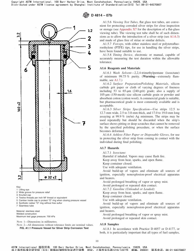
A1.5.6 Viewing Test Tubes, flat glass test tubes, are conve-nient for protecting corroded silver strips for close inspectionor storage (see Appendix X7 for the description of a flat-glassviewing tube). The viewing test tube shall be of such dimen-sions as to allow the introduction of a silver strip (see A1.6.3)and made of glass free of striae or similar defects.
A1.5.7 Forceps, with either stainless steel or polytetrafluo-roethylene (PTFE) tips, for use in handling the silver strips,have been found suitable to use.
A1.5.8 Timing Device, electronic or manual, capable ofaccurately measuring the test duration within the allowabletolerance.
A1.6 Reagents and Materials
A1.6.1 Wash Solvent—2,2,4-trimethylpentane (isooctane)of minimum 99.75 % purity. (Warning—extremely flam-mable, see A1.7.)
A1.6.2 Surface Preparation/Polishing Materials, siliconcarbide grit paper or cloth of varying degrees of finenessincluding 53 to 65-µm (240-grit) grade; also a supply of105-µm (150-mesh) size silicon carbide grain or powder andabsorbent cotton (cotton wool). A commercial grade is suitable,but pharmaceutical grade is most commonly available and isacceptable.
A1.6.3 Silver Strips Specification—Use strips 12.5 to12.7-mm wide, 2.5 to 3.0-mm thick, and 17.0 to 19.0-mm longassaying at 99.9 % (m/m) Ag minimum. The strips may beused repeatedly but should be discarded when the strip’ssurface shows pitting or deep scratches that cannot be removedby the specified polishing procedure, or when the surfacebecomes deformed.
A1.6.4 Ashless Filter Paper or Disposable Gloves, for usein protecting the silver strip from coming in contact with theindividual during final polishing.
A1.7 Hazards
A1.7.1 Isooctane:Harmful if inhaled. Vapors may cause flash fire.Keep away from heat, sparks, and open flame.Keep container closed.Use with adequate ventilation.Avoid build-up of vapors and eliminate all sources of
ignition, especially nonexplosion-proof electrical apparatusand heaters.
Avoid prolonged breathing of vapor or spray mist.Avoid prolonged or repeated skin contact.A1.7.2 Gasoline (Unleaded or Leaded):Keep away from heat, sparks, and open flame.Keep container closed.Use with adequate ventilation.Avoid build-up of vapors and eliminate all sources of
ignition, especially nonexplosion-proof electrical apparatusand heaters.
Avoid prolonged breathing of vapor or spray mist.Avoid prolonged or repeated skin contact.
A1.8 Samples
A1.8.1 In accordance with Practice D 4057 or D 4177, orboth, it is particularly important that all types of fuel samples,
Key:1 Lifting eye2 Wide groove for pressure relief3 Knurled cap4 Twelve threads per inch NF thread or equivalent5 Camber inside cap to protect “O” ring when closing pressure vessel6 Synthetic rubber “O” ring without free sulfur7 Seamless tube
Material: stainless steelWelded constructionMaximum test gage pressure: 700 kPa
NOTE 1—Dimensions in millimetres.NOTE 2—All dimensions without tolerance limits are nominal values.
FIG. A1.1 Pressure Vessel for Silver Strip Corrosion Test
D 4814 – 07b
10
Copyright ASTM International, 100 Barr Harbor Drive, West Conshohocken, Pennsylvania 19428, USADistributed under ASTM license agreement by Shanghai Institute of Standardization(SIS) Tel:86-21-64370807
ASTM International 版权所有, 100 Barr Harbor Drive, West Conshohocken, Pennsylvania, 19428, USA由上海市标准化研究院(SIS)根据ASTM授权协议进行销售 地址:上海市长乐路1219/1227号 邮编:200031 联系电话:86-21-64370807

that pass a low-tarnish strip classification, be collected in clean,dark glass bottles, plastic bottles, or other suitable containersthat will not affect the corrosive properties of the fuel. Avoidthe use of tin plate containers for collection of samples, sinceexperience has shown that they may contribute to the corro-siveness of the sample.
A1.8.2 Fill the containers as completely as possible andclose them immediately after taking the sample. Adequateheadspace in the container is necessary to provide room forpossible thermal expansion during transport. It is recom-mended that volatile samples be filled between 70 and 80 % ofthe container’s capacity. Take care during sampling to protectthe samples from exposure to direct sunlight or even diffuseddaylight. Carry out the test as soon as possible after receipt inthe laboratory and immediately after opening the container.
A1.8.3 If suspended water (that is, haze) is observed in thesample, dry by filtering a sufficient volume of sample throughmedium rapid qualitative filter paper, into the prescribed clean,dry test tube. Carry out this operation in a darkened room orunder a light-protected shield.
A1.8.3.1 Contact of the silver strip with water before,during or after completion of the test run will cause staining,making it difficult to evaluate the strips.
A1.9 Preparation of Test Strips
A1.9.1 Surface Preparation—Remove all surface blemishesfrom all six sides of the strip obtained from a previous analysis(see Note A1.1). Use silicon carbide paper or cloth of suchdegrees of fineness as are needed to accomplish the desiredresults efficiently. Finish with 53 to 65-µm (240-grit) siliconcarbide paper or cloth, removing all marks that may have beenmade by other grades of paper used previously. Immerse thestrip in 2,2,4-trimethylpentane from which it can be withdrawnimmediately for final preparation (polishing) or in which it canbe stored for future use.
NOTE A1.1—Only final preparation (A1.9.2) is necessary for commer-cially purchased pre-polished strips.
A1.9.1.1 As a practical manual procedure for surface prepa-ration, place a sheet of silicon carbide paper or cloth on a flatsurface and moisten it with 2,2,4-trimethylpentane. Rub thestrip against the silicon carbide paper or cloth with a circularmotion, protecting the strip from contact with the fingers byusing ashless filter paper or wearing disposable gloves. Alter-natively, the surface of the strip can be prepared by use ofmotor-driven machines using appropriate grades of dry paperor cloth.
A1.9.2 Final Preparation—For strips prepared in A1.9.1 ornew strips being used for the first time, remove a strip from the2,2,4-trimethylpentane. To prevent possible surface contami-nation during final preparation, do not allow fingers to come indirect contact with the silver strips, by wearing disposablegloves or holding the strips in the fingers protected with ashlessfilter paper. Polish first the ends and then the sides with the105-µm (150-mesh) silicon carbide grains or powder picked upwith a pad of cotton (cotton wool) moistened with 2,2,4-trimethylpentane. Wipe vigorously with fresh pads of cotton(cotton wool) and subsequently handle without touching thesurface of the strip with the fingers. Forceps have been found
suitable to use. Clamp in a vise and polish the main surfaceswith silicon-carbide grains on absorbent cotton. Do not polishin a circular motion. Rub in the direction of the long axis of thestrip, carrying the stroke beyond the end of the strip beforereversing the direction. Clean all metal dust from the strip byrubbing vigorously with clean pads of absorbent cotton until afresh pad remains unsoiled. When the strip is clean, immedi-ately immerse it in the prepared sample.
A1.9.2.1 It is important to polish the whole surface of thestrip uniformly to obtain a uniformly stained strip. If the edgesshow wear (surface elliptical), they will likely show morecorrosion than the center. The use of a vise (see Appendix X7)will facilitate uniform polishing.
A1.9.2.2 It is important to follow the order of preparationwith the correctly sized silicon carbide material as described inA1.9.1 and A1.9.2. The final preparation is with 105-µm siliconcarbide grains or powder. This is a larger grain size than the 53to 65-µm paper used in the surface preparation stage. Thereason for this use of larger silicon carbide grains in the finalpreparation is to produce asperities (controlled roughness) onthe surface of the silver, which act as sites for the initiation ofcorrosion reactions.
A1.10 Procedure
A1.10.1 Pressure Vessel Procedure:A1.10.1.1 Place 30 mL of sample, completely clear and free
of any suspended or entrained water (see A1.8.3) into achemically clean and dry 25-mm by 150-mm test tube. Within1 min after completing the final preparation (polishing), slidethe silver strip into the sample tube. Place the sample tube intothe pressure vessel (Fig. A1.1) and screw the lid on tightly. Ifmore than one sample is to be analyzed at essentially the sametime, it is permissible to prepare each pressure vessel in thebatch before completely immersing each pressure vessel in theliquid bath at 50 6 1°C (122 6 2°F), provided the elapsed timebetween the first and last samples is kept to a minimum. After3 h 6 5 min in the bath, withdraw the pressure vessel andimmerse for a few minutes in cool water (tap water). Open thepressure vessel, withdraw the test tube and examine the strip asdescribed in A1.10.2.
A1.10.2 Strip Examination:A1.10.2.1 Immediately withdraw the strip with forceps and
immerse in 2,2,4-trimethylpentane. Withdraw the strip at once,dry it with ashless filter paper (by blotting not wiping) andinspect it for evidence of tarnishing or corrosion.
A1.10.2.2 In handling the test strip during the inspectionand comparison, the danger of marking or staining can beavoided if it is inserted in a flat glass tube (see Appendix X7),which can be stoppered with absorbent cotton.
A1.11 Interpretation of Results
A1.11.1 Interpret the corrosiveness of the sample by com-paring the appearance of the test strip with a freshly polishedone to give a classification based on that given in Table A1.1.All surfaces, including the edges, shall be taken into account.
A1.11.1.1 The Color Standard for Tube Deposit Rating9
(referenced in Test Method D 3241) shall be used to differen-tiate between the brown colorations mentioned in classifica-tions 1 and 2. Any brown coloration less than No. 4 on the
D 4814 – 07b
11
Copyright ASTM International, 100 Barr Harbor Drive, West Conshohocken, Pennsylvania 19428, USADistributed under ASTM license agreement by Shanghai Institute of Standardization(SIS) Tel:86-21-64370807
ASTM International 版权所有, 100 Barr Harbor Drive, West Conshohocken, Pennsylvania, 19428, USA由上海市标准化研究院(SIS)根据ASTM授权协议进行销售 地址:上海市长乐路1219/1227号 邮编:200031 联系电话:86-21-64370807
Color Standard shall be rated classification 1. Any colorationequal to or darker than No. 4 on the Color Standard shall berated as classification 2 or higher.
A1.12 Report
A1.12.1 Report the corrosiveness in accordance with one ofthe classifications listed in Table A1.1. State the duration of thetest and the test temperature in the following format:
Corrosion silver strip ~Xh / Y°C!, Classification Z (A1.1)
where:X = test duration, in hours,Y = test temperature, °C, andZ = classification category (that is, 0, 1, 2, 3, or 4).
A1.13 Precision and Bias
A1.13.1 The precision and bias of this test method has notbeen determined.
APPENDIXES
(Nonmandatory Information)
X1. SIGNIFICANCE OF ASTM SPECIFICATION FOR AUTOMOTIVE SPARK-IGNITION ENGINE FUEL
X1.1 General
X1.1.1 Antiknock rating and volatility define the generalcharacteristics of automotive spark-ignition engine fuel. Othercharacteristics relate to the following: limiting the concentra-tion of undesirable components so that they will not adverselyaffect engine performance and ensuring the stability of fuel aswell as its compatibility with materials used in engines andtheir fuel systems.
X1.1.2 Fuel for spark-ignition engines is a complex mixturecomposed of relatively volatile hydrocarbons that vary widelyin their physical and chemical properties and may containoxygenates. Fuel is exposed to a wide variety of mechanical,physical, and chemical environments. Thus, the properties offuel must be balanced to give satisfactory engine performanceover an extremely wide range of operating conditions. Theprevailing standards for fuel represent compromises among thenumerous quality and performance requirements. This ASTMspecification is established on the basis of the broad experienceand close cooperation of producers of fuel, manufacturers ofautomotive equipment, and users of both.
X1.2 Engine Knock
X1.2.1 The fuel-air mixture in the cylinder of a spark-ignition engine will, under certain conditions, autoignite inlocalized areas ahead of the flame front that is progressing fromthe spark. This is engine spark knock which can cause a pingthat may be audible to the customer.
X1.2.2 The antiknock rating of a fuel is a measure of itsresistance to knock. The antiknock requirement of an enginedepends on engine design and operation, as well as atmo-spheric conditions. Fuel with an antiknock rating higher thanthat required for knock-free operation does not improveperformance.
X1.2.3 A decrease in antiknock rating may cause vehicleperformance loss. However, vehicles equipped with knock
limiters can show a performance improvement as the antiknockquality of the fuel is increased in the range between customer-audible knock and knock-free operation. The loss of power andthe damage to an automotive engine due to knocking aregenerally not significant until the knock intensity becomes verysevere. Heavy and prolonged knocking may cause power lossand damage to the engine.
X1.3 Laboratory Octane Number
X1.3.1 The two recognized laboratory engine test methodsfor determining the antiknock rating of fuels are the Researchmethod (Test Methods D 2699 or D 2885) and the Motormethod (Test Methods D 2700 or D 2885). The followingparagraphs define the two methods and describe their signifi-cance as applied to various equipment and operating condi-tions.
X1.3.2 Research octane number is determined by a methodthat measures fuel antiknock level in a single-cylinder engineunder mild operating conditions; namely, at a moderate inletmixture temperature and a low engine speed. Research octanenumber tends to indicate fuel antiknock performance in en-gines at wide-open throttle and low-to-medium engine speeds.
X1.3.3 Motor octane number is determined by a methodthat measures fuel antiknock level in a single-cylinder engineunder more severe operating conditions than those employed inthe Research method; namely, at a higher inlet mixturetemperature and at a higher engine speed. It indicates fuelantiknock performance in engines operating at wide-openthrottle and high engine speeds. Also, Motor octane numbertends to indicate fuel antiknock performance under part-throttle, road-load conditions.
X1.4 Road Octane Number
X1.4.1 The road octane of a fuel is the measure of its abilityto resist knock in customers’ vehicles, and is ultimately of
TABLE A1.1 Silver Strip Classifications
Classification Designation Description
0 No tarnish Identical to a freshly polished strip, but mayhave some very light loss of luster
1 Slight tarnish Faint brown or white discoloration of strip(see A1.11.1.1)
2 Moderate tarnish Peacock colors such as blue or mauve ormedium/dark straw or brown coloration(see A1.11.1.1)
3 Slight blackening Spots and patches of black or gray on surfaceor uniform thin film of black deposit
4 Blackening Uniform heavy blackening with or withoutscaling
D 4814 – 07b
12
Copyright ASTM International, 100 Barr Harbor Drive, West Conshohocken, Pennsylvania 19428, USADistributed under ASTM license agreement by Shanghai Institute of Standardization(SIS) Tel:86-21-64370807
ASTM International 版权所有, 100 Barr Harbor Drive, West Conshohocken, Pennsylvania, 19428, USA由上海市标准化研究院(SIS)根据ASTM授权协议进行销售 地址:上海市长乐路1219/1227号 邮编:200031 联系电话:86-21-64370807
more importance than laboratory octane numbers. Since roadoctanes are difficult to measure and interpret, the industry hasagreed to use ASTM laboratory engine tests to estimate theroad octane performance of spark-ignition engine fuel invehicles.
X1.4.2 The antiknock index (AKI) is the arithmetic averageof the Research octane number (RON) and Motor octanenumber (MON):
AKI 5 ~RON 1 MON!/2 (X1.1)
This value is called by a variety of names, in addition toantiknock index, including:
Octane ratingPosted octane(R + M)/2 octane
X1.4.3 The AKI is posted on retail gasoline dispensingpumps in the United States and is referred to in car owners’manuals. The AKI is also required for certification at eachwholesale fuel transfer and is referred to in United Statesfederal law as “Octane Rating.”10
X1.4.4 The most extensive data base that relates the labo-ratory engine test methods for Research and Motor octane toactual field performance of fuel in vehicles is the annualCoordinating Research Council (CRC)11 Octane Number Re-quirement Survey conducted for new light-duty vehicles.Analysis of these data shows that the antiknock performance ofa fuel in some vehicles may correlate best with Researchoctane number, while in others, it may correlate best withMotor octane number. These correlations also differ frommodel year to model year or from vehicle population to vehiclepopulation, reflecting changes in engine designs over the years.
X1.4.5 The antiknock index of a fuel approximates the CRCroad octane ratings for many vehicles. However, the user mustalso be guided by experience as to which fuel is mostappropriate for an individual vehicle. The antiknock indexformula is reviewed periodically and may have to be adjustedin the future as engines and fuels continue to evolve. Thepresent (RON + MON)/2 formula is an estimate and is not anabsolute measure of fuel antiknock performance in general orin any specific vehicle.
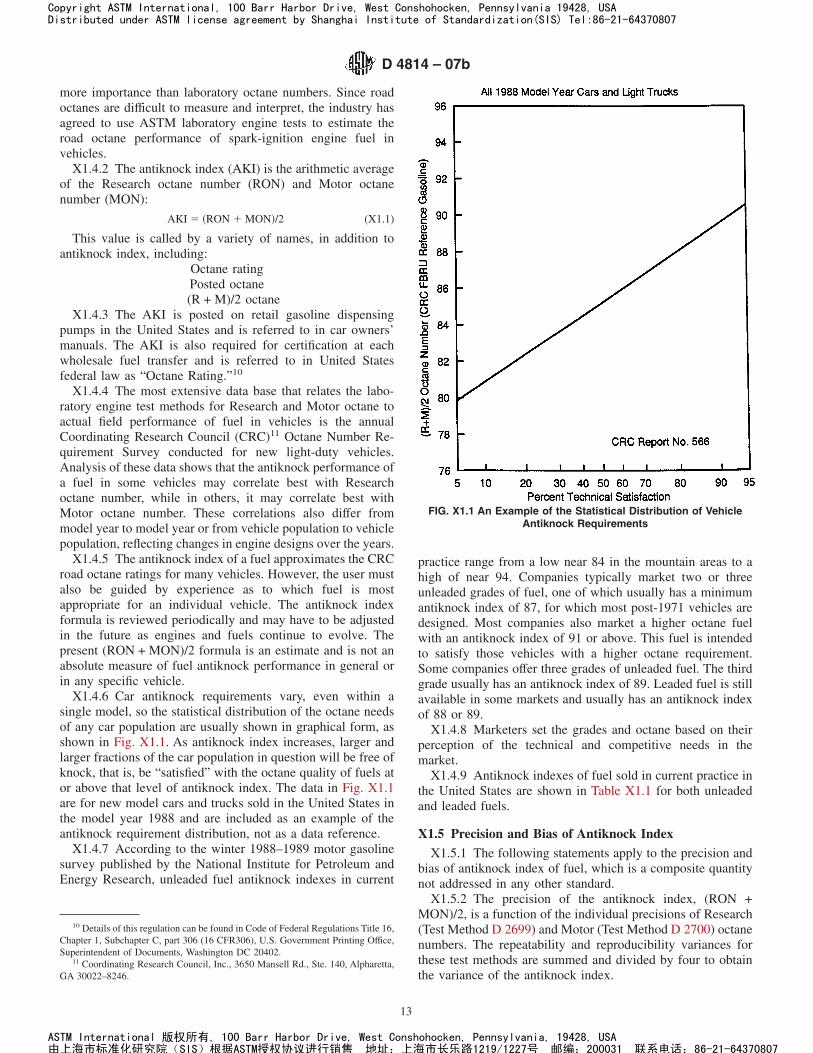
X1.4.6 Car antiknock requirements vary, even within asingle model, so the statistical distribution of the octane needsof any car population are usually shown in graphical form, asshown in Fig. X1.1. As antiknock index increases, larger andlarger fractions of the car population in question will be free ofknock, that is, be “satisfied” with the octane quality of fuels ator above that level of antiknock index. The data in Fig. X1.1are for new model cars and trucks sold in the United States inthe model year 1988 and are included as an example of theantiknock requirement distribution, not as a data reference.
X1.4.7 According to the winter 1988–1989 motor gasolinesurvey published by the National Institute for Petroleum andEnergy Research, unleaded fuel antiknock indexes in current
practice range from a low near 84 in the mountain areas to ahigh of near 94. Companies typically market two or threeunleaded grades of fuel, one of which usually has a minimumantiknock index of 87, for which most post-1971 vehicles aredesigned. Most companies also market a higher octane fuelwith an antiknock index of 91 or above. This fuel is intendedto satisfy those vehicles with a higher octane requirement.Some companies offer three grades of unleaded fuel. The thirdgrade usually has an antiknock index of 89. Leaded fuel is stillavailable in some markets and usually has an antiknock indexof 88 or 89.
X1.4.8 Marketers set the grades and octane based on theirperception of the technical and competitive needs in themarket.
X1.4.9 Antiknock indexes of fuel sold in current practice inthe United States are shown in Table X1.1 for both unleadedand leaded fuels.
X1.5 Precision and Bias of Antiknock Index
X1.5.1 The following statements apply to the precision andbias of antiknock index of fuel, which is a composite quantitynot addressed in any other standard.
X1.5.2 The precision of the antiknock index, (RON +MON)/2, is a function of the individual precisions of Research(Test Method D 2699) and Motor (Test Method D 2700) octanenumbers. The repeatability and reproducibility variances forthese test methods are summed and divided by four to obtainthe variance of the antiknock index.
10 Details of this regulation can be found in Code of Federal Regulations Title 16,Chapter 1, Subchapter C, part 306 (16 CFR306), U.S. Government Printing Office,Superintendent of Documents, Washington DC 20402.
11 Coordinating Research Council, Inc., 3650 Mansell Rd., Ste. 140, Alpharetta,GA 30022–8246.
FIG. X1.1 An Example of the Statistical Distribution of VehicleAntiknock Requirements
D 4814 – 07b
13
Copyright ASTM International, 100 Barr Harbor Drive, West Conshohocken, Pennsylvania 19428, USADistributed under ASTM license agreement by Shanghai Institute of Standardization(SIS) Tel:86-21-64370807
ASTM International 版权所有, 100 Barr Harbor Drive, West Conshohocken, Pennsylvania, 19428, USA由上海市标准化研究院(SIS)根据ASTM授权协议进行销售 地址:上海市长乐路1219/1227号 邮编:200031 联系电话:86-21-64370807
X1.5.2.1 Repeatability—The difference between two sets ofantiknock index determinations, where two test results by eachoctane number method were obtained by one operator, with thesame apparatus under constant operating conditions on identi-cal test material would, in the long run, and in the normal andcorrect operation of the test methods, exceed the values in thefollowing table in only one case in twenty.
X1.5.2.2 Reproducibility—The difference between two in-dependent sets of antiknock index determinations, obtained bydifferent operators working in different laboratories on identi-cal test material would, in the long run, and in the normal andcorrect operation of the test methods, exceed the values in thefollowing table in only one case in twenty.
Antiknock IndexRepeatability,
Antiknock Index UnitsReproducibility,
Antiknock Index Units
83 0.2 0.785 0.2 0.787 0.2 0.689 0.2 0.691 0.2 0.693 0.2 0.695 — 0.697 — 0.7
NOTE X1.1—These precision values were calculated from Research andMotor octane number results utilizing exchange sample test data obtainedby the ASTM National Exchange Group (NEG), the Institute of Petro-leum, or the Institut Français du Petrole, or combination thereof, partici-pating in cooperative testing programs. The precision values for 83, 85,95, and 97 AKI were obtained from NEG data during the period 1980through 1982 and have been analyzed in accordance with RR: D02-1007,“Manual on Determining Precision Data for ASTM Methods on PetroleumProducts and Lubricants,” Spring 1973.12 The precision values for 87though 93 AKI were calculated using the data from RR: D02-1383,“Research and Motor Octane Number Precision Study Report, 1988
through 1994,” December 1995.13
X1.5.2.3 Bias—Since knock ratings are determined by theconditions of the empirical test methods involved, bias cannotbe determined.
X1.6 Effects of Altitude and Weather on VehicleAntiknock Requirement
X1.6.1 A vehicle’s antiknock requirement can vary withchanges in altitude, ambient temperature, and humidity, de-pending on the control system of the vehicle. New vehicleshave sensors to measure and engine management computers,which take into account such conditions as air charge tempera-ture and barometric pressure. These vehicles are designed tohave the same antiknock requirement at all altitudes and areduced sensitivity to changes in ambient temperature. Thismore sophisticated control technology began to be used exten-sively in 1984. This technology, while constantly evolving andimproving, is used on almost all new vehicles. This means thatmany vehicles in today’s fleet require fuel having the sameantiknock index regardless of changes in altitude or ambienttemperatures. Older vehicles, which do not have sophisticatedcontrol systems, will likely experience changes in antiknockrequirement due to changes in altitude and weather conditions.However, the changes in antiknock requirement indicated inthe following sections apply to a continually smaller part of thevehicle fleet.
X1.6.2 The antiknock requirement of an older vehicledecreases as altitude increases, primarily due to reduction inmixture density caused by reduced atmospheric pressure. Thechange in antiknock requirement for altitude for older vehiclesis given in Fig. X1.2. Boundaries of the areas defined and thecorresponding antiknock index reductions were established toprotect vehicles driven from a higher altitude to a loweraltitude (and, hence higher antiknock requirement) area whileusing a fuel obtained in the high altitude area.
X1.6.3 Tests by CRC and other organizations have shownthat the decrease in antiknock requirements with altitude islarger for most models between 1971 and 1984, designed to usea fuel with an antiknock index of 87, than for pre-1971vehicles. Generally the pre-1971 vehicles have high compres-sion ratios and were designed for fuels with an antiknock indexof 88 or higher. Fuels with antiknock indexes below 89 areadjusted by a larger factor than those with an antiknock indexof 89 or greater.
X1.6.4 The antiknock requirements of older vehicles risewith increasing ambient temperature on the average by 0.097MON per degree Celsius (0.054 MON per degree Fahrenheit).
X1.6.5 The antiknock requirements of both older and newvehicles decrease with increasing specific humidity by 0.245MON per gram of water per kilogram of dry air (0.035 MONper grain of water per pound of dry air).
X1.6.6 Because temperature and humidity of geographicalareas are predictable throughout the year from past weatherrecords, antiknock index levels can be adjusted to matchseasonal changes in vehicle antiknock requirements. Fig. X1.3
12 Supporting data have been filed at ASTM International Headquarters and maybe obtained by requesting Research Report RR: D02–1007.
13 Supporting data have been filed at ASTM International Headquarters and maybe obtained by requesting Research Report RR: D02–1383.
TABLE X1.1 Automotive Spark-Ignition Engine Fuel AntiknockIndexes in Current Practice
Unleaded FuelA
(for vehicles that can or must use unleaded fuel)Antiknock IndexB,C,D,E
(RON + MON)/2Application
87 Designed to meet antiknock requirements of most1971 and later model vehicles
89 Satisfies vehicles with somewhat higher antiknockrequirements
91 and above Satisfies vehicles with high antiknock requirementsLeaded Fuel
(for vehicles that can or must use leaded fuel)Antiknock IndexB,C,D,E
(RON + MON)/2Application
88 For most vehicles that were designed to operate onleaded fuel
A Unleaded fuel having an antiknock index of at least 87 should also have aminimum Motor octane number of 82 in order to adequately protect those vehiclesthat are sensitive to Motor octane quality.
B Reductions in vehicle antiknock requirements for altitude are shown in Fig.X1.2.
C Reductions in vehicle antiknock requirements for seasonal variations areshown in Fig. X1.3.
D Not all antiknock index levels listed in this table are available at all locations.E The Federal Trade Commission requires octane posting and certification in
accordance with 16 CFR Part 306.
D 4814 – 07b
14
Copyright ASTM International, 100 Barr Harbor Drive, West Conshohocken, Pennsylvania 19428, USADistributed under ASTM license agreement by Shanghai Institute of Standardization(SIS) Tel:86-21-64370807
ASTM International 版权所有, 100 Barr Harbor Drive, West Conshohocken, Pennsylvania, 19428, USA由上海市标准化研究院(SIS)根据ASTM授权协议进行销售 地址:上海市长乐路1219/1227号 邮编:200031 联系电话:86-21-64370807
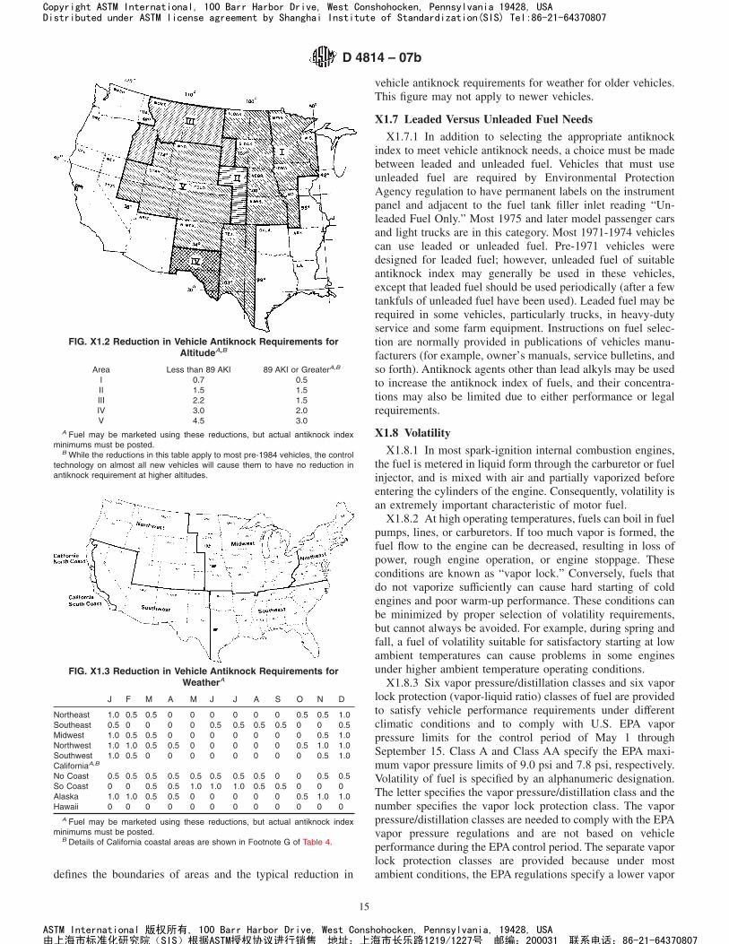
defines the boundaries of areas and the typical reduction in
vehicle antiknock requirements for weather for older vehicles.This figure may not apply to newer vehicles.
X1.7 Leaded Versus Unleaded Fuel Needs
X1.7.1 In addition to selecting the appropriate antiknockindex to meet vehicle antiknock needs, a choice must be madebetween leaded and unleaded fuel. Vehicles that must useunleaded fuel are required by Environmental ProtectionAgency regulation to have permanent labels on the instrumentpanel and adjacent to the fuel tank filler inlet reading “Un-leaded Fuel Only.” Most 1975 and later model passenger carsand light trucks are in this category. Most 1971-1974 vehiclescan use leaded or unleaded fuel. Pre-1971 vehicles weredesigned for leaded fuel; however, unleaded fuel of suitableantiknock index may generally be used in these vehicles,except that leaded fuel should be used periodically (after a fewtankfuls of unleaded fuel have been used). Leaded fuel may berequired in some vehicles, particularly trucks, in heavy-dutyservice and some farm equipment. Instructions on fuel selec-tion are normally provided in publications of vehicles manu-facturers (for example, owner’s manuals, service bulletins, andso forth). Antiknock agents other than lead alkyls may be usedto increase the antiknock index of fuels, and their concentra-tions may also be limited due to either performance or legalrequirements.
X1.8 Volatility
X1.8.1 In most spark-ignition internal combustion engines,the fuel is metered in liquid form through the carburetor or fuelinjector, and is mixed with air and partially vaporized beforeentering the cylinders of the engine. Consequently, volatility isan extremely important characteristic of motor fuel.
X1.8.2 At high operating temperatures, fuels can boil in fuelpumps, lines, or carburetors. If too much vapor is formed, thefuel flow to the engine can be decreased, resulting in loss ofpower, rough engine operation, or engine stoppage. Theseconditions are known as “vapor lock.” Conversely, fuels thatdo not vaporize sufficiently can cause hard starting of coldengines and poor warm-up performance. These conditions canbe minimized by proper selection of volatility requirements,but cannot always be avoided. For example, during spring andfall, a fuel of volatility suitable for satisfactory starting at lowambient temperatures can cause problems in some enginesunder higher ambient temperature operating conditions.
X1.8.3 Six vapor pressure/distillation classes and six vaporlock protection (vapor-liquid ratio) classes of fuel are providedto satisfy vehicle performance requirements under differentclimatic conditions and to comply with U.S. EPA vaporpressure limits for the control period of May 1 throughSeptember 15. Class A and Class AA specify the EPA maxi-mum vapor pressure limits of 9.0 psi and 7.8 psi, respectively.Volatility of fuel is specified by an alphanumeric designation.The letter specifies the vapor pressure/distillation class and thenumber specifies the vapor lock protection class. The vaporpressure/distillation classes are needed to comply with the EPAvapor pressure regulations and are not based on vehicleperformance during the EPA control period. The separate vaporlock protection classes are provided because under mostambient conditions, the EPA regulations specify a lower vapor
FIG. X1.2 Reduction in Vehicle Antiknock Requirements forAltitudeA,B
Area Less than 89 AKI 89 AKI or GreaterA,B
I 0.7 0.5II 1.5 1.5III 2.2 1.5IV 3.0 2.0V 4.5 3.0
A Fuel may be marketed using these reductions, but actual antiknock indexminimums must be posted.
B While the reductions in this table apply to most pre-1984 vehicles, the controltechnology on almost all new vehicles will cause them to have no reduction inantiknock requirement at higher altitudes.
FIG. X1.3 Reduction in Vehicle Antiknock Requirements forWeatherA
J F M A M J J A S O N D
Northeast 1.0 0.5 0.5 0 0 0 0 0 0 0.5 0.5 1.0Southeast 0.5 0 0 0 0 0.5 0.5 0.5 0.5 0 0 0.5Midwest 1.0 0.5 0.5 0 0 0 0 0 0 0 0.5 1.0Northwest 1.0 1.0 0.5 0.5 0 0 0 0 0 0.5 1.0 1.0Southwest 1.0 0.5 0 0 0 0 0 0 0 0 0.5 1.0CaliforniaA,B
No Coast 0.5 0.5 0.5 0.5 0.5 0.5 0.5 0.5 0 0 0.5 0.5So Coast 0 0 0.5 0.5 1.0 1.0 1.0 0.5 0.5 0 0 0Alaska 1.0 1.0 0.5 0.5 0 0 0 0 0 0.5 1.0 1.0Hawaii 0 0 0 0 0 0 0 0 0 0 0 0
A Fuel may be marketed using these reductions, but actual antiknock indexminimums must be posted.
B Details of California coastal areas are shown in Footnote G of Table 4.
D 4814 – 07b
15
Copyright ASTM International, 100 Barr Harbor Drive, West Conshohocken, Pennsylvania 19428, USADistributed under ASTM license agreement by Shanghai Institute of Standardization(SIS) Tel:86-21-64370807
ASTM International 版权所有, 100 Barr Harbor Drive, West Conshohocken, Pennsylvania, 19428, USA由上海市标准化研究院(SIS)根据ASTM授权协议进行销售 地址:上海市长乐路1219/1227号 邮编:200031 联系电话:86-21-64370807
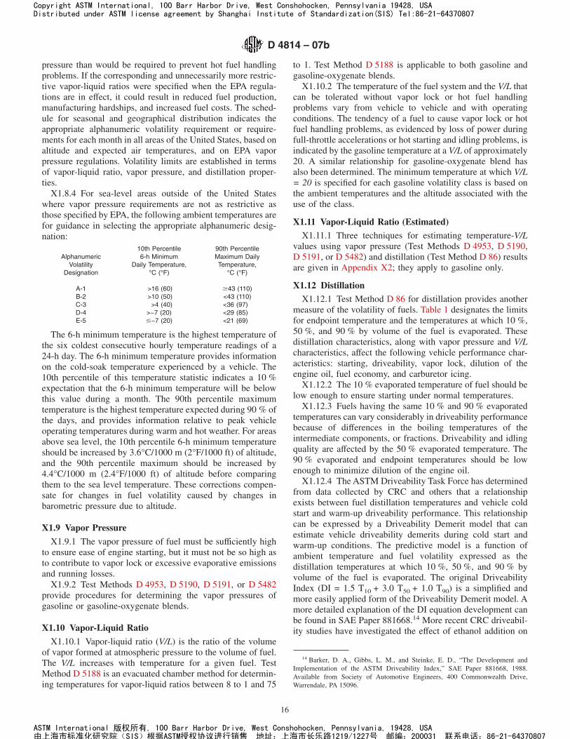
pressure than would be required to prevent hot fuel handlingproblems. If the corresponding and unnecessarily more restric-tive vapor-liquid ratios were specified when the EPA regula-tions are in effect, it could result in reduced fuel production,manufacturing hardships, and increased fuel costs. The sched-ule for seasonal and geographical distribution indicates theappropriate alphanumeric volatility requirement or require-ments for each month in all areas of the United States, based onaltitude and expected air temperatures, and on EPA vaporpressure regulations. Volatility limits are established in termsof vapor-liquid ratio, vapor pressure, and distillation proper-ties.
X1.8.4 For sea-level areas outside of the United Stateswhere vapor pressure requirements are not as restrictive asthose specified by EPA, the following ambient temperatures arefor guidance in selecting the appropriate alphanumeric desig-nation:
10th Percentile 90th PercentileAlphanumeric 6-h Minimum Maximum Daily
Volatility Daily Temperature, Temperature,Designation °C (°F) °C (°F)
A-1 >16 (60) $43 (110)B-2 >10 (50) <43 (110)C-3 >4 (40) <36 (97)D-4 >−7 (20) <29 (85)E-5 #−7 (20) <21 (69)
The 6-h minimum temperature is the highest temperature ofthe six coldest consecutive hourly temperature readings of a24-h day. The 6-h minimum temperature provides informationon the cold-soak temperature experienced by a vehicle. The10th percentile of this temperature statistic indicates a 10 %expectation that the 6-h minimum temperature will be belowthis value during a month. The 90th percentile maximumtemperature is the highest temperature expected during 90 % ofthe days, and provides information relative to peak vehicleoperating temperatures during warm and hot weather. For areasabove sea level, the 10th percentile 6-h minimum temperatureshould be increased by 3.6°C/1000 m (2°F/1000 ft) of altitude,and the 90th percentile maximum should be increased by4.4°C/1000 m (2.4°F/1000 ft) of altitude before comparingthem to the sea level temperature. These corrections compen-sate for changes in fuel volatility caused by changes inbarometric pressure due to altitude.
X1.9 Vapor Pressure
X1.9.1 The vapor pressure of fuel must be sufficiently highto ensure ease of engine starting, but it must not be so high asto contribute to vapor lock or excessive evaporative emissionsand running losses.
X1.9.2 Test Methods D 4953, D 5190, D 5191, or D 5482provide procedures for determining the vapor pressures ofgasoline or gasoline-oxygenate blends.
X1.10 Vapor-Liquid Ratio
X1.10.1 Vapor-liquid ratio (V/L) is the ratio of the volumeof vapor formed at atmospheric pressure to the volume of fuel.The V/L increases with temperature for a given fuel. TestMethod D 5188 is an evacuated chamber method for determin-ing temperatures for vapor-liquid ratios between 8 to 1 and 75
to 1. Test Method D 5188 is applicable to both gasoline andgasoline-oxygenate blends.
X1.10.2 The temperature of the fuel system and the V/L thatcan be tolerated without vapor lock or hot fuel handlingproblems vary from vehicle to vehicle and with operatingconditions. The tendency of a fuel to cause vapor lock or hotfuel handling problems, as evidenced by loss of power duringfull-throttle accelerations or hot starting and idling problems, isindicated by the gasoline temperature at a V/L of approximately20. A similar relationship for gasoline-oxygenate blend hasalso been determined. The minimum temperature at which V/L= 20 is specified for each gasoline volatility class is based onthe ambient temperatures and the altitude associated with theuse of the class.
X1.11 Vapor-Liquid Ratio (Estimated)
X1.11.1 Three techniques for estimating temperature-V/Lvalues using vapor pressure (Test Methods D 4953, D 5190,D 5191, or D 5482) and distillation (Test Method D 86) resultsare given in Appendix X2; they apply to gasoline only.
X1.12 Distillation
X1.12.1 Test Method D 86 for distillation provides anothermeasure of the volatility of fuels. Table 1 designates the limitsfor endpoint temperature and the temperatures at which 10 %,50 %, and 90 % by volume of the fuel is evaporated. Thesedistillation characteristics, along with vapor pressure and V/Lcharacteristics, affect the following vehicle performance char-acteristics: starting, driveability, vapor lock, dilution of theengine oil, fuel economy, and carburetor icing.
X1.12.2 The 10 % evaporated temperature of fuel should below enough to ensure starting under normal temperatures.
X1.12.3 Fuels having the same 10 % and 90 % evaporatedtemperatures can vary considerably in driveability performancebecause of differences in the boiling temperatures of theintermediate components, or fractions. Driveability and idlingquality are affected by the 50 % evaporated temperature. The90 % evaporated and endpoint temperatures should be lowenough to minimize dilution of the engine oil.
X1.12.4 The ASTM Driveability Task Force has determinedfrom data collected by CRC and others that a relationshipexists between fuel distillation temperatures and vehicle coldstart and warm-up driveability performance. This relationshipcan be expressed by a Driveability Demerit model that canestimate vehicle driveability demerits during cold start andwarm-up conditions. The predictive model is a function ofambient temperature and fuel volatility expressed as thedistillation temperatures at which 10 %, 50 %, and 90 % byvolume of the fuel is evaporated. The original DriveabilityIndex (DI = 1.5 T10 + 3.0 T50 + 1.0 T90) is a simplified andmore easily applied form of the Driveability Demerit model. Amore detailed explanation of the DI equation development canbe found in SAE Paper 881668.14 More recent CRC driveabil-ity studies have investigated the effect of ethanol addition on
14 Barker, D. A., Gibbs, L. M., and Steinke, E. D., “The Development andImplementation of the ASTM Driveability Index,” SAE Paper 881668, 1988.Available from Society of Automotive Engineers, 400 Commonwealth Drive,Warrendale, PA 15096.
D 4814 – 07b
16
Copyright ASTM International, 100 Barr Harbor Drive, West Conshohocken, Pennsylvania 19428, USADistributed under ASTM license agreement by Shanghai Institute of Standardization(SIS) Tel:86-21-64370807
ASTM International 版权所有, 100 Barr Harbor Drive, West Conshohocken, Pennsylvania, 19428, USA由上海市标准化研究院(SIS)根据ASTM授权协议进行销售 地址:上海市长乐路1219/1227号 邮编:200031 联系电话:86-21-64370807
cold start and warm-up driveability. The ASTM DriveabilityTask Force decided that an upward adjustment for ethanol isneeded in the DI equation as follows:
DI 5 1.5 T10 1 3.0 T50 1 1.0 T90 1 1.33°C ~2.4°F! 3 Ethanol Volume %,
as shown in Table 4,
where:1.33 = coefficient for the volume % ethanol present when
the distillation results are determined in degreesCelsius, and
2.4 = coefficient when the distillation results are deter-mined in degrees Fahrenheit.
X1.13 Corrosion
X1.13.1 Fuels must pass the copper strip corrosion test tominimize corrosion in fuel systems due to sulfur compounds inthe fuel. Some fuels corrode fuel system metals other thancopper, but there are no ASTM test methods to evaluatecorrosion of these metals. Depending on the type and concen-tration of oxygenate, gasoline-oxygenate blends can corrodemetals such as zinc, magnesium, aluminum, steel, and terne.However, at this time there is no test method with a knowncorrelation to field performance. Consequently, additionalcorrosion tests are needed.
X1.13.2 Reactive sulfur compounds present in automotivespark-ignition engine fuel under some circumstances cancorrode or tarnish silver alloy fuel gauge in-tank sender units.To minimize the failure of silver alloy in-tank sender units bycorrosion or tarnish, fuels must pass the silver strip corrosiontest.
X1.14 Solvent-Washed Gum Content
X1.14.1 The test for solvent-washed gum content measuresthe amount of residue after evaporation of the fuel andfollowing a heptane wash. The heptane wash removes theheptane-soluble, non-volatile material such as additives, carrier
oils used with additives, and heavier hydrocarbons such asdiesel fuels, and so forth. Solvent-washed gum consists offuel-insoluble gum and fuel-soluble gum. The fuel-insolubleportion can clog fuel filters. Both can be deposited on surfaceswhen the fuel evaporates.
X1.14.2 Solvent-washed gum can contribute to deposits onthe surfaces of carburetors, fuel injectors, and intake mani-folds, ports, valves, and valve guides. The impact of solvent-washed gum on malfunctions of modern engines is not wellestablished and the current specification limit is historic ratherthan the result of recent correlative studies. It depends onwhere the deposits form; the presence of other deposit precur-sors, such as airborne debris, blowby and exhaust gas recircu-lation gases, and oxidized engine oil; and the amount ofdeposits.
X1.14.3 The difference between the unwashed and solvent-washed gum content values can be used to assess the presenceand amount of nonvolatile material in the fuel. Additionalanalytical testing is required to determine if the material isadditive, carrier oil, diesel fuel, and so forth.
X1.15 Sulfur
X1.15.1 The limit on sulfur content is included to protectagainst engine wear, deterioration of engine oil, and corrosionof exhaust system parts.
X1.16 Oxidation Stability
X1.16.1 The induction period as measured in the oxidationstability test is used as an indication of the resistance of fuel togum formation in storage. Experience indicates that fuels withan induction period equal to or greater than that in Table 2generally have acceptable short-term storage stability. How-ever, correlation of the induction period with the formation ofgum in storage can vary markedly under different storageconditions and with different fuels.
X2. ESTIMATING TEMPERATURE-V/L VALUES FOR GASOLINE
X2.1 Scope
X2.1.1 Three techniques are presented here for estimatingtemperature-V/L data from vapor pressure and distillation testresults15 on gasolines only. They are provided for use as aguideline when V/L data measured by Test Method D 5188 arenot available. One method is designed for computer process-ing, one is a simpler linear technique, while the other is anomogram form of this linear equation.
X2.1.2 These techniques are not optional procedures formeasuring temperature–V/L. They are supplementary tools for
estimating temperature-V/L relationships with reasonable ac-curacy when used with due regard for their limitations.
X2.1.3 Test Method D 5188 is the referee V/L procedureand shall be used when calculated values are questionable.
X2.1.4 These techniques are not intended for, nor are theynecessarily applicable to, fuels of extreme distillation orchemical characteristics, such as would be outside the range ofnormal commercial motor gasolines. Thus, they are not appli-cable in all instances to gasoline blending stocks or speciallyblended fuels.
X2.2 Computer Method
X2.2.1 Summary—The values of four intermediate func-tions, A, B, C, and D, are derived from the gasoline vaporpressure and distillation temperatures at 10, 20, and 50 %evaporated. Values for A, B, C, and D can be obtained eitherfrom equations or from a set of charts. Sections X2.2.2.1-X2.2.2.3 provide A, B, C, and D values using SI units;
15 A correlation of temperature-V/ L ratio data with vapor pressure anddistillation data was developed in 1943 and restudied in 1963 by panels of theCoordinating Research Council, Inc. See “Correlation of Gasoline Vapor FormingCharacteristics with Inspection Test Data,” CRC Report No. 159, Jan. 28, 1943 (orSAE Transaction, Vol 52, August 1944, pp. 364–367) and “Study of CRC CalculatedTemperature-V/L Technique,” CRC Report No. 370, February 1963. The CRCcorrelation was modified by a task group of Subcommittee A of Committee D02 toadapt it for computer processing, as well as the linear equation and the nomogram.
D 4814 – 07b
17
Copyright ASTM International, 100 Barr Harbor Drive, West Conshohocken, Pennsylvania 19428, USADistributed under ASTM license agreement by Shanghai Institute of Standardization(SIS) Tel:86-21-64370807
ASTM International 版权所有, 100 Barr Harbor Drive, West Conshohocken, Pennsylvania, 19428, USA由上海市标准化研究院(SIS)根据ASTM授权协议进行销售 地址:上海市长乐路1219/1227号 邮编:200031 联系电话:86-21-64370807
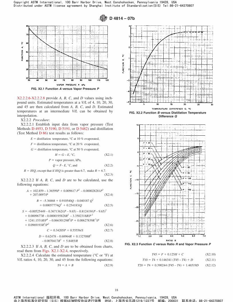
X2.2.2.6-X2.2.2.8 provide A, B, C, and D values using inch-pound units. Estimated temperatures at a V/L of 4, 10, 20, 30,and 45 are then calculated from A, B, C, and D. Estimatedtemperatures at an intermediate V/L can be obtained byinterpolation.
X2.2.2 Procedure:X2.2.2.1 Establish input data from vapor pressure (Test
Methods D 4953, D 5190, D 5191, or D 5482) and distillation(Test Method D 86) test results as follows:
E 5 distillation temperature, °C at 10 % evaporated,
F 5 distillation temperature, °C at 20 % evaporated,
G 5 distillation temperature, °C at 50 % evaporated,
H 5 G – E, °C, (X2.1)
P 5 vapor pressure, kPa,
Q 5 F– E, °C, and (X2.2)
R 5 H/Q, except that if H/Q is greater than 6.7, make R 5 6.7.(X2.3)
X2.2.2.2 If A, B, C, and D are to be calculated, use thefollowing equations:
A 5 102.859 – 1.36599P 1 0.009617 P2 – 0.000028281P3
1 207.0097/P (X2.4)
B 5 –5.36868 1 0.910540Q – 0.040187 Q2
1 0.00057774Q3 1 0.254183/Q (X2.5)
S 5 –0.00525449 – 0.3671362/~P – 9.65! – 0.812419/~P – 9.65!2
1 0.0009677R – 0.0000195828R2 – 3.3502318R/P 2
1 1241.1531R/P4 – 0.06630129R2/P 1 0.00627839R 3/P
1 0.0969193R2/P2 (X2.6)
C 5 0.34205P 1 0.55556/S (X2.7)
D 5 0.62478 – 0.68964R 1 0.132708R2
– 0.0070417R3 1 5.8485/R (X2.8)
X2.2.2.3 If A, B, C, and D are to be obtained from charts,read them from Figs. X2.1-X2.4, respectively.
X2.2.2.4 Calculate the estimated temperature (°C or °F) atV/L ratios 4, 10, 20, 30, and 45 from the following equations:
T4 5 A 1 B (X2.9)
T45 5 F 1 0.125H 1 C (X2.10)
T10 5 T4 1 0.146341 ~T45 – T4! 1 D (X2.11)
T20 5 T4 1 0.390244 ~T45 – T4! 1 1.46519D (X2.12)
FIG. X2.1 Function A versus Vapor Pressure P
FIG. X2.2 Function B versus Distillation TemperatureDifference Q
FIG. X2.3 Function C versus Ratio R and Vapor Pressure P
D 4814 – 07b
18
Copyright ASTM International, 100 Barr Harbor Drive, West Conshohocken, Pennsylvania 19428, USADistributed under ASTM license agreement by Shanghai Institute of Standardization(SIS) Tel:86-21-64370807
ASTM International 版权所有, 100 Barr Harbor Drive, West Conshohocken, Pennsylvania, 19428, USA由上海市标准化研究院(SIS)根据ASTM授权协议进行销售 地址:上海市长乐路1219/1227号 邮编:200031 联系电话:86-21-64370807

T30 5 T4 1 0.634146 ~T45 – T4! 1 D (X2.13)
where:T4, T10, T20, T30, and T45 are estimated temperatures at V/Lratios, 4, 10, 20, 30, and 45, respectively.
X2.2.2.5 If the temperature at an intermediate V/L ratio is tobe estimated, either plot the values calculated in X2.2.2.4 andread the desired value from a smooth curve through the points,or use the Lagrange interpolation formula as follows:
TX 5 T4 SX – 104 – 10 3
X – 304 – 30 3
X – 454 – 45D
1 T10S X – 410 – 4 3
X – 3010 – 30 3
X – 4510 – 45D
1 T30S X – 430 – 4 3
X – 1030 – 10 3
X – 4530 – 45D
1 T45 S X – 445 – 4 3
X – 1045 – 10 3
X – 3045 – 30D (X2.14)
where:X = the desired V/L ratio between 4 and 45, andTX = the estimated temperature at V/L ratio X.
X2.2.2.6 If inch-pound units are used, establish input datafrom vapor pressure (Test Methods D 4953, D 5190, D 5191,or D 5482) and distillation (Test Method D 86) test results asfollows:
E 5 distillation temperature, °F at 10 % evaporated,
F 5 distillation temperature, °F at 20 % evaporated,
G 5 distillation temperature, °F at 50 % evaporated,
H 5 G – E, °F (X2.15)
P 5 vapor pressure, psi,
Q 5 F – E, °F, and (X2.16)
R 5 H/Q, except that if H/Q is greater than 6.7,make R5 6.7. (X2.17)
X2.2.2.7 If A, B, C, and D are to be calculated in inch-poundunits, use the following equations:
A 5 217.147 – 16.9527P 1 0.822909P2 – 0.0166849P3
1 54.0436/P (X2.18)
B 5 – 9.66363 1 0.910540Q – 0.0223260Q2
1 0.000178314Q3 1 0.823553/Q (X2.19)
S 5 –0.00525449 – 0.0532486/~P – 1.4!
– 0.0170900/~P – 1.4!2 1 0.0009677R –
0.0000195828R2 – 0.0704753R/P 2 1 0.549224R/P4
– 0.00961619R2/P 1 0.000910603R3/P
1 0.00203879R2/P2 (X2.20)
C 5 4.245P 1 1.0/S (X2.21)
D 5 1.12460 – 1.24135R 1 0.238875R2
– 0.0126750R3 1 10.5273/R (X2.22)
X2.2.2.8 If A, B, C, and D are to be obtained from charts ininch-pound units, read them from Figs. X2.5-X2.8, respec-tively.
X2.2.2.9 Calculate the estimated temperatures, °F, at V/Lratios 4, 10, 20, 30, and 45 using the equations in X2.2.2.4 andX2.2.2.5.
X2.3 Linear Equation Method
X2.3.1 Summary—As given, these two equations provideonly the temperatures (°C or °F) at which a V/L value of 20exists. They make use of two points from the distillation curve,T10 and T50 (°C or °F), and the vapor pressure (kPa or psi) ofthe gasoline with constant weighting factors being applied toeach. Experience has shown that data obtained with thesesimple linear equations generally are in close agreement withthose obtained by the computerized version given above. Thelimitations pointed out in X2.1.1-X2.1.4 must be kept in mindwhen use is made of this procedure.
X2.3.2 Procedure—Obtain 10 % evaporated and 50 %evaporated points from the distillation curve (Test MethodD 86) along with the vapor pressure value (Test MethodsD 4953, D 5190, D 5191, or D 5482); apply these directly inthe equation.
TV/L520 5 52.47 – 0.33 ~VP! 1 0.20 T10 1 0.17 T50 (X2.23)
where:TV/L = 20 = temperature, °C, at V/L of 20:1,VP = vapor pressure, kPa,T10 = distillation temperature, °C, at 10 % evapo-
rated, andT50 = distillation temperature, °C, at 50 % evapo-
rated.or in the inch-pound customary unit equation:
FIG. X2.4 Function D versus Ratio R
FIG. X2.5 Function A versus Vapor Pressure P
D 4814 – 07b
19
Copyright ASTM International, 100 Barr Harbor Drive, West Conshohocken, Pennsylvania 19428, USADistributed under ASTM license agreement by Shanghai Institute of Standardization(SIS) Tel:86-21-64370807
ASTM International 版权所有, 100 Barr Harbor Drive, West Conshohocken, Pennsylvania, 19428, USA由上海市标准化研究院(SIS)根据ASTM授权协议进行销售 地址:上海市长乐路1219/1227号 邮编:200031 联系电话:86-21-64370807
TV/L520 5 114.6 – 4.1 ~VP! 1 0.20 T10 1 0.17 T50 (X2.24)
where:TV/L = 20 = temperature, °F, at V/L of 20:1,VP = vapor pressure, psi,T10 = distillation temperature, °F, at 10 % evapo-
rated, andT50 = distillation temperature, °F, at 50 % evapo-
rated.
X2.4 Nomogram Method
X2.4.1 Summary—Two nomograms have been developedand are included in this specification (Figs. X2.9 and X2.10) toprovide the same function as the linear equations procedureoutlined above. Fig. X2.9 is in SI units and Fig. X2.10 is ininch-pound units. The nomograms are based on the twoequations and the same limitations apply to their use inestimating V/L (20) temperatures.
X2.4.2 Procedure—Obtain 10 % evaporated and 50 %evaporated points from the distillation curve (Test MethodD 86) along with the vapor pressure value (Test MethodsD 4953, D 5190, D 5191, or D 5482). Select the SI unit (Fig.X2.9) or inch-pound unit (Fig. X2.10) nomogram based on theunits of T10, T50, and VP. Using a straightedge, locate theintercept on the line between the “T10 and T50” scales afterselecting the applicable T10 and T50 values. From this interceptand the proper point on the “VP” scale, a second intercept canbe obtained on the “T V/L = 20” scale to provide the desired valuedirectly.
X2.5 Precision
X2.5.1 The precision of agreement between temperature-V/L data estimated by any one of these three techniques anddata obtained by Test Method D 5188 has not been established.
FIG. X2.6 Function B versus Distillation TemperatureDifference Q
FIG. X2.7 Function C versus Ratio R and Vapor Pressure P
FIG. X2.8 Function D versus Ratio R
D 4814 – 07b
20
Copyright ASTM International, 100 Barr Harbor Drive, West Conshohocken, Pennsylvania 19428, USADistributed under ASTM license agreement by Shanghai Institute of Standardization(SIS) Tel:86-21-64370807
ASTM International 版权所有, 100 Barr Harbor Drive, West Conshohocken, Pennsylvania, 19428, USA由上海市标准化研究院(SIS)根据ASTM授权协议进行销售 地址:上海市长乐路1219/1227号 邮编:200031 联系电话:86-21-64370807
FIG. X2.9 Relationship Between Gasoline Volatility and Temperature for V/L Ratio at Sea Level—SI Units
D 4814 – 07b
21
Copyright ASTM International, 100 Barr Harbor Drive, West Conshohocken, Pennsylvania 19428, USADistributed under ASTM license agreement by Shanghai Institute of Standardization(SIS) Tel:86-21-64370807
ASTM International 版权所有, 100 Barr Harbor Drive, West Conshohocken, Pennsylvania, 19428, USA由上海市标准化研究院(SIS)根据ASTM授权协议进行销售 地址:上海市长乐路1219/1227号 邮编:200031 联系电话:86-21-64370807
X3. SUMMARY OF EPA REGULATIONS APPLICABLE TO SPARK-IGNITION ENGINE FUEL
X3.1 EPA Applicable Vapor Pressure Standards
X3.1.1 Under authority of the Clean Air Act, the U.S.Environmental Protection Agency (EPA) issued, effective May1992, vapor pressure control standards for leaded and unleadedgasoline and leaded and unleaded gasoline-oxygenate blends.Some states, notably California, have more restrictive vaporpressure limits.
X3.1.2 Details of the EPA regulations and test methods areavailable in Part 80 of Title 40 of the Code of FederalRegulations (40 CFR Part 80). For specific state vapor pressureregulations, the state of interest should be contacted.
X3.1.3 The EPA maximum vapor pressure limits of 7.8 psiand 9.0 psi are shown in Table 1 as Classes AA and A,respectively. The EPA requirements for each distribution areaare shown in Table 4 for the period May 1 through September15. For the month of May, the EPA limits only apply to finishedgasoline and gasoline-oxygenate blend tankage at refineries,importers, pipelines, and terminals. For the period June 1through September 15, the EPA limits apply to all locations ofthe distribution system. Footnotes C, D, and F of Table 4indicate the ozone nonattainment areas which are limited to 7.8psi maximum and the appropriate vapor lock protection class.
California has controls that vary for the different air basinsfrom as early as March 1 at refineries through as late asOctober 31. There are no EPA vapor pressure limits for thestates of Alaska or Hawaii.
X3.1.4 EPA regulations allow 1.0 psi higher values forgasoline-ethanol blends than the EPA limits shown in Table 1and Table 4 for the period May 1 through September 15. Toqualify, the gasoline-ethanol blends must contain 9 to 10volume % ethanol. Higher vapor pressure limits for gasoline-ethanol blends under state regulations vary for other timeperiods, and specific states of interest should be contacted todetermine if higher limits apply.
X3.2 EPA Lead and Phosphorus Regulations
X3.2.1 Unleaded Fuel—The intentional addition of lead orphosphorus compounds to unleaded fuel is not permitted by theEPA. EPA regulations limit their maximum concentrations to0.05 g lead/U.S. gal (0.013 g/L) and 0.005 g of phosphorus/U.S. gal (0.0013 g/L) (see Test Method D 3231), respectively.
X3.2.2 Leaded Fuel—EPA regulations after December 31,1995 prohibit the sale, supply, dispensing, transporting, orintroducing into commerce a fuel for use in any motor vehicle
FIG. X2.10 Relationship Between Gasoline Volatility and Temperature for V/L Ratio of 20 at Sea Level—Inch-Pound Units
D 4814 – 07b
22
Copyright ASTM International, 100 Barr Harbor Drive, West Conshohocken, Pennsylvania 19428, USADistributed under ASTM license agreement by Shanghai Institute of Standardization(SIS) Tel:86-21-64370807
ASTM International 版权所有, 100 Barr Harbor Drive, West Conshohocken, Pennsylvania, 19428, USA由上海市标准化研究院(SIS)根据ASTM授权协议进行销售 地址:上海市长乐路1219/1227号 邮编:200031 联系电话:86-21-64370807
which is produced with the use of lead additives or whichcontains more than 0.05 g lead/U.S. gal (0.013 g/L).
X3.2.2.1 The regulations define motor vehicle to includeany self-propelled vehicle designed for transporting persons orproperty on a street or highway.
X3.2.2.2 The regulations do not prohibit the use of leadadditives in fuel used in aircraft, racing cars, and nonroadengines, such as farm equipment engines and marine engines.
X3.3 EPA Oxygenate Regulations Applicable to UnleadedGasoline-Oxygenate Blends
X3.3.1 Substantially Similar Rule:X3.3.1.1 Section 211(f) (1) of the Clean Air Act prohibits
introducing into commerce or increasing the concentration inuse of, any fuel or fuel additive, which is not substantiallysimilar to any fuel or fuel additive utilized for emissionscertification of any model year 1975, or subsequent model yearvehicle or engine, unless a waiver is obtained from the EPA.
X3.3.1.2 Gasoline-oxygenate blends are considered “sub-stantially similar” if the following criteria are met.
(1) The fuel must contain carbon, hydrogen, and oxygen,nitrogen, or sulfur, or combination thereof, exclusively, in theform of some combination of the following:
(a) Hydrocarbons;(b) Aliphatic ethers;(c) Aliphatic alcohols other than methanol;(d) (i) Up to 0.3 volume % methanol;
(ii) Up to 2.75 volume % methanol with an equalvolume of butanol, or higher molecular weight alcohol;
(2) The fuel must contain no more than 2.0 mass % oxygenexcept fuels containing aliphatic ethers and/or alcohols (ex-cluding methanol) must contain no more than 2.7 mass %oxygen.
(3) The fuel must possess, at the time of manufacture, all ofthe physical and chemical characteristics of an unleadedgasoline as specified by Specification D 4814 – 88 for at leastone of the Seasonal and Geographical Volatility Classesspecified in the standard.
X3.3.2 Waivers:X3.3.2.1 EPA has issued waivers for blends of gasoline and
ethanol (gasohol), gasoline and ethanol with cosolvents, andgasoline and methanol with cosolvents that are less limitingthan the “substantially similar” rule. For the latest listing ofwaivers, EPA should be contacted.
X3.3.2.2 Gasoline-ethanol blends are not required by EPAto meet Specification D 4814 volatility limits (see X3.1.4 forvapor pressure limits). EPA has specified in all other waiversthat the volatility of the finished gasoline-oxygenate blendmust comply with Specification D 439 or D 4814 climatic andgeographical limits.
X3.4 EPA Reformulated Gasoline (RFG)
X3.4.1 Reformulated gasoline (RFG) is a spark-ignitionengine fuel formulated to reduce motor vehicle emissions oftoxic and tropospheric ozone-forming compounds. The CleanAir Act Amendments of 1990 require that RFG be sold in ninemetropolitan areas with the worst summertime ozone levels.Other areas that do not meet ambient ozone standards maypetition EPA to require RFG. The various RFG regulations
have been established by the EPA. EPA has also placed limitson conventional gasoline sold in the rest of the U.S. to preventRFG producers from using conventional gasoline as an outletfor undesirable fuel components (anti-dumping requirements).The EPA requirements became effective at the retail level onJanuary 1, 1995.
X3.4.2 The characteristics of reformulated spark-ignitionengine fuel, beyond those described by this specification, aredescribed in the research report on reformulated spark-ignitionengine fuel.2 The research report also includes information onCalifornia Air Resources Board Phase 2 gasoline requirements,which are more restrictive than the EPA RFG requirements andtake effect at the retail level on June 1, 1996.
X3.5 EPA Certification Standards for Deposit ControlGasoline Additives
X3.5.1 Beginning August 1, 1997, except for some fuelspecific certifications, fuel sold or transferred to the ultimateconsumer must contain detergent additive(s) meeting the EPAcertification requirements. The regulation applies to fuelswhether intended for on-highway or nonroad use, includingconventional, reformulated, oxygenated, and leaded gasolines,as well as fuels used in marine service, and the gasolinecomponent of M85 and E85 fuel alcohols. Racing fuel fornon-highway use in racing vehicles and aviation fuel used inaircraft are exempted. Fuels used for research, development,and testing and federal emissions certification fuels can beexempted.
X3.5.2 As of July 1, 1997, only certified detergents may beused by detergent blenders, and distributors may only sell ortransfer fuel that is properly additized with certified detergents.Detergent additives may be certified for nationwide use, forgeographical use based on Petroleum Administration Districtsfor Defense (PADDs), or for a fuel-specific option for segre-gated gasoline pools. Certification sub-options allow a deter-gent to be certified for use in premium-grade, nonoxygenated,or oxygenate-specific fuel. A California Air Resources Boardadditive certification will be accepted for fuel additized or usedonly in California. Specific minimum fuel properties (aromat-ics, sulfur content, olefins content, and 90 % evaporated point)for each option are required for certification and the certifica-tion fuels must also meet the requirements of SpecificationD 4814-95c. For some options, the addition of 10 volume %ethanol is required for certification fuel. Other oxygenates mayalso be required. Testing is required to demonstrate that thecertification fuels without additives form a minimum level ofintake valve deposits if specially formulated from refineryblend stocks. Such deposit demonstration testing is not re-quired for test fuels sampled directly from finished fuels,fuel-specific test fuels, CARB-based certifications, and leadedgasoline certifications.
X3.5.3 For additive certification, the test fuel containing thedetergent additive(s) must form less than 100 mg/valve averageintake valve deposit weight after 10 000 miles of testing inaccordance with Test Method D 5500-94. In addition, after10 000 miles of testing, there may be no more than 5 % flowrestriction in any one fuel injector in accordance with TestMethod D 5598-94.
D 4814 – 07b
23
Copyright ASTM International, 100 Barr Harbor Drive, West Conshohocken, Pennsylvania 19428, USADistributed under ASTM license agreement by Shanghai Institute of Standardization(SIS) Tel:86-21-64370807
ASTM International 版权所有, 100 Barr Harbor Drive, West Conshohocken, Pennsylvania, 19428, USA由上海市标准化研究院(SIS)根据ASTM授权协议进行销售 地址:上海市长乐路1219/1227号 邮编:200031 联系电话:86-21-64370807
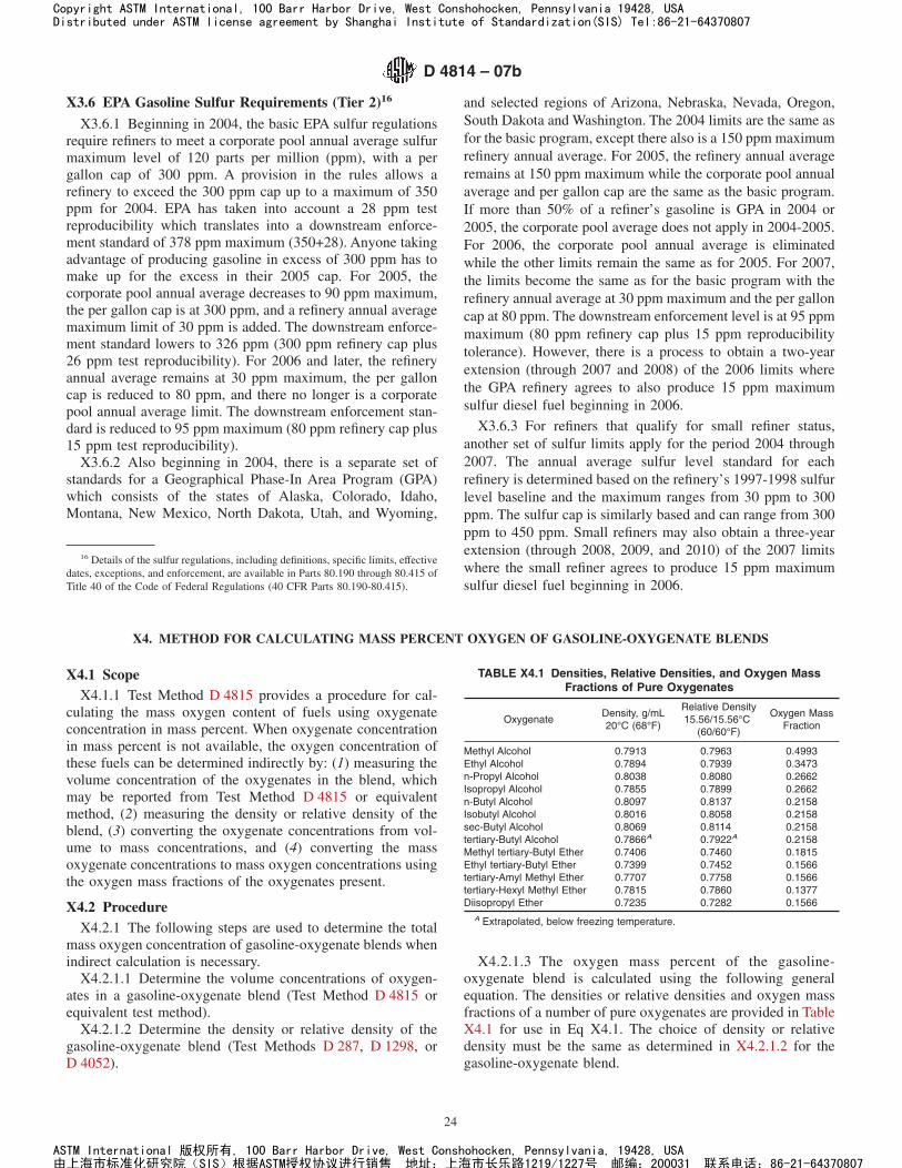
X3.6 EPA Gasoline Sulfur Requirements (Tier 2)16
X3.6.1 Beginning in 2004, the basic EPA sulfur regulationsrequire refiners to meet a corporate pool annual average sulfurmaximum level of 120 parts per million (ppm), with a pergallon cap of 300 ppm. A provision in the rules allows arefinery to exceed the 300 ppm cap up to a maximum of 350ppm for 2004. EPA has taken into account a 28 ppm testreproducibility which translates into a downstream enforce-ment standard of 378 ppm maximum (350+28). Anyone takingadvantage of producing gasoline in excess of 300 ppm has tomake up for the excess in their 2005 cap. For 2005, thecorporate pool annual average decreases to 90 ppm maximum,the per gallon cap is at 300 ppm, and a refinery annual averagemaximum limit of 30 ppm is added. The downstream enforce-ment standard lowers to 326 ppm (300 ppm refinery cap plus26 ppm test reproducibility). For 2006 and later, the refineryannual average remains at 30 ppm maximum, the per galloncap is reduced to 80 ppm, and there no longer is a corporatepool annual average limit. The downstream enforcement stan-dard is reduced to 95 ppm maximum (80 ppm refinery cap plus15 ppm test reproducibility).
X3.6.2 Also beginning in 2004, there is a separate set ofstandards for a Geographical Phase-In Area Program (GPA)which consists of the states of Alaska, Colorado, Idaho,Montana, New Mexico, North Dakota, Utah, and Wyoming,
and selected regions of Arizona, Nebraska, Nevada, Oregon,South Dakota and Washington. The 2004 limits are the same asfor the basic program, except there also is a 150 ppm maximumrefinery annual average. For 2005, the refinery annual averageremains at 150 ppm maximum while the corporate pool annualaverage and per gallon cap are the same as the basic program.If more than 50% of a refiner’s gasoline is GPA in 2004 or2005, the corporate pool average does not apply in 2004-2005.For 2006, the corporate pool annual average is eliminatedwhile the other limits remain the same as for 2005. For 2007,the limits become the same as for the basic program with therefinery annual average at 30 ppm maximum and the per galloncap at 80 ppm. The downstream enforcement level is at 95 ppmmaximum (80 ppm refinery cap plus 15 ppm reproducibilitytolerance). However, there is a process to obtain a two-yearextension (through 2007 and 2008) of the 2006 limits wherethe GPA refinery agrees to also produce 15 ppm maximumsulfur diesel fuel beginning in 2006.
X3.6.3 For refiners that qualify for small refiner status,another set of sulfur limits apply for the period 2004 through2007. The annual average sulfur level standard for eachrefinery is determined based on the refinery’s 1997-1998 sulfurlevel baseline and the maximum ranges from 30 ppm to 300ppm. The sulfur cap is similarly based and can range from 300ppm to 450 ppm. Small refiners may also obtain a three-yearextension (through 2008, 2009, and 2010) of the 2007 limitswhere the small refiner agrees to produce 15 ppm maximumsulfur diesel fuel beginning in 2006.
X4. METHOD FOR CALCULATING MASS PERCENT OXYGEN OF GASOLINE-OXYGENATE BLENDS
X4.1 ScopeX4.1.1 Test Method D 4815 provides a procedure for cal-
culating the mass oxygen content of fuels using oxygenateconcentration in mass percent. When oxygenate concentrationin mass percent is not available, the oxygen concentration ofthese fuels can be determined indirectly by: (1) measuring thevolume concentration of the oxygenates in the blend, whichmay be reported from Test Method D 4815 or equivalentmethod, (2) measuring the density or relative density of theblend, (3) converting the oxygenate concentrations from vol-ume to mass concentrations, and (4) converting the massoxygenate concentrations to mass oxygen concentrations usingthe oxygen mass fractions of the oxygenates present.
X4.2 ProcedureX4.2.1 The following steps are used to determine the total
mass oxygen concentration of gasoline-oxygenate blends whenindirect calculation is necessary.
X4.2.1.1 Determine the volume concentrations of oxygen-ates in a gasoline-oxygenate blend (Test Method D 4815 orequivalent test method).
X4.2.1.2 Determine the density or relative density of thegasoline-oxygenate blend (Test Methods D 287, D 1298, orD 4052).
X4.2.1.3 The oxygen mass percent of the gasoline-oxygenate blend is calculated using the following generalequation. The densities or relative densities and oxygen massfractions of a number of pure oxygenates are provided in TableX4.1 for use in Eq X4.1. The choice of density or relativedensity must be the same as determined in X4.2.1.2 for thegasoline-oxygenate blend.
16 Details of the sulfur regulations, including definitions, specific limits, effectivedates, exceptions, and enforcement, are available in Parts 80.190 through 80.415 ofTitle 40 of the Code of Federal Regulations (40 CFR Parts 80.190-80.415).
TABLE X4.1 Densities, Relative Densities, and Oxygen MassFractions of Pure Oxygenates
OxygenateDensity, g/mL20°C (68°F)
Relative Density15.56/15.56°C
(60/60°F)
Oxygen MassFraction
Methyl Alcohol 0.7913 0.7963 0.4993Ethyl Alcohol 0.7894 0.7939 0.3473n-Propyl Alcohol 0.8038 0.8080 0.2662Isopropyl Alcohol 0.7855 0.7899 0.2662n-Butyl Alcohol 0.8097 0.8137 0.2158Isobutyl Alcohol 0.8016 0.8058 0.2158sec-Butyl Alcohol 0.8069 0.8114 0.2158tertiary-Butyl Alcohol 0.7866A 0.7922A 0.2158Methyl tertiary-Butyl Ether 0.7406 0.7460 0.1815Ethyl tertiary-Butyl Ether 0.7399 0.7452 0.1566tertiary-Amyl Methyl Ether 0.7707 0.7758 0.1566tertiary-Hexyl Methyl Ether 0.7815 0.7860 0.1377Diisopropyl Ether 0.7235 0.7282 0.1566
A Extrapolated, below freezing temperature.
D 4814 – 07b
24
Copyright ASTM International, 100 Barr Harbor Drive, West Conshohocken, Pennsylvania 19428, USADistributed under ASTM license agreement by Shanghai Institute of Standardization(SIS) Tel:86-21-64370807
ASTM International 版权所有, 100 Barr Harbor Drive, West Conshohocken, Pennsylvania, 19428, USA由上海市标准化研究院(SIS)根据ASTM授权协议进行销售 地址:上海市长乐路1219/1227号 邮编:200031 联系电话:86-21-64370807
Oxygen, Mass % 5
V 1 3 d1 3 O1 1 V2 3 d2 3 O2 . . . 1 Vn 3 d n 3 O n
Vb 3 d b3 100
(X4.1)
where:Vn = volume % of oxygenates 1 through n,dn = density or relative density of oxygenates 1 through n,On = mass fraction oxygen in oxygenates 1 through n,Vb = volume % of gasoline-oxygenate blend = 100, anddb = density or relative density of gasoline-oxygenate
blend.
X4.3 Example Calculation
X4.3.1 Assume that a gasoline-oxygenate blend is reportedto contain 9.5 volume % ethanol and 2.0 volume % methyltertiary-butyl ether and that the relative density of the blend ismeasured to be 0.7450, 15.56/15.56°C (60/60°F).
X4.3.2 Using the relative density and oxygen mass fractiondata for ethanol and methyl tertiary-butyl ether from TableX4.1, the following mass % oxygen is calculated for thisgasoline-oxygenate blend.
Oxygen, Mass % 5 (X4.2)
9.5 3 0.7939 3 0.3473 1 2.0 3 0.7460 3 0.1815100 3 0.7450 3 100 5 3.88
X4.4 Precision
X4.4.1 The precision of this calculation method is a func-tion of the individual precisions of density or relative density(Test Methods D 287, D 1298, or D 4052) and oxygenateanalysis (Test Method D 4815 or equivalent). Because therepeatability and reproducibility vary with the analyses used,no estimate is provided.
X5. MICROBIAL CONTAMINATION
X5.1 Uncontrolled microbial contamination in fuel systemsmay cause or contribute to a variety of problems includingincreased corrosivity, and decreased stability, filterability, andcaloric value. Microbial processes in fuel systems may alsocause or contribute to system damage.
X5.2 Because the microbes contributing to the aforemen-tioned problems may not be present in the fuel itself, nomicrobial quality criterion for fuels is recommended. However,
it is important that personnel responsible for fuel qualityunderstand how uncontrolled microbial contamination mayaffect fuel quality.
X5.3 Guide D 6469 provides personnel with limited micro-biological background an understanding of the symptoms,occurrences, and consequences of chronic microbial contami-nation. Guide D 6469 also suggests means for detecting andcontrolling microbial contamination in fuels and fuel systems.
X6. FUEL FILTRATION
X6.1 During the distribution of spark-ignition fuels, it ispossible for them to become contaminated with potential filterblocking materials. While proper handling will minimize the
contamination levels, it is recommended that all fuel dispensersbe equipped with filters of 10 µm or less nominal pore size atpoint of delivery to the customer.
X7. OPTIONAL USEFUL EQUIPMENT FOR SILVER STRIP TEST
X7.1 Viewing Tube
X7.1.1 A useful flat glass test tube for holding tarnishedsilver strips for inspection or for storage for later inspection isillustrated and dimensioned in Fig. X7.1.
X7.2 Strip Vise
X7.2.1 A useful and convenient vise for holding up to foursilver strips during final polishing is illustrated and dimen-sioned in Fig. X7.2.
D 4814 – 07b
25
Copyright ASTM International, 100 Barr Harbor Drive, West Conshohocken, Pennsylvania 19428, USADistributed under ASTM license agreement by Shanghai Institute of Standardization(SIS) Tel:86-21-64370807
ASTM International 版权所有, 100 Barr Harbor Drive, West Conshohocken, Pennsylvania, 19428, USA由上海市标准化研究院(SIS)根据ASTM授权协议进行销售 地址:上海市长乐路1219/1227号 邮编:200031 联系电话:86-21-64370807
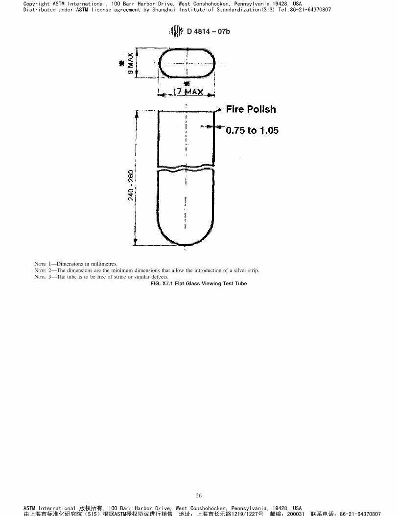
NOTE 1—Dimensions in millimetres.NOTE 2—The dimensions are the minimum dimensions that allow the introduction of a silver strip.NOTE 3—The tube is to be free of striae or similar defects.
FIG. X7.1 Flat Glass Viewing Test Tube
D 4814 – 07b
26
Copyright ASTM International, 100 Barr Harbor Drive, West Conshohocken, Pennsylvania 19428, USADistributed under ASTM license agreement by Shanghai Institute of Standardization(SIS) Tel:86-21-64370807
ASTM International 版权所有, 100 Barr Harbor Drive, West Conshohocken, Pennsylvania, 19428, USA由上海市标准化研究院(SIS)根据ASTM授权协议进行销售 地址:上海市长乐路1219/1227号 邮编:200031 联系电话:86-21-64370807
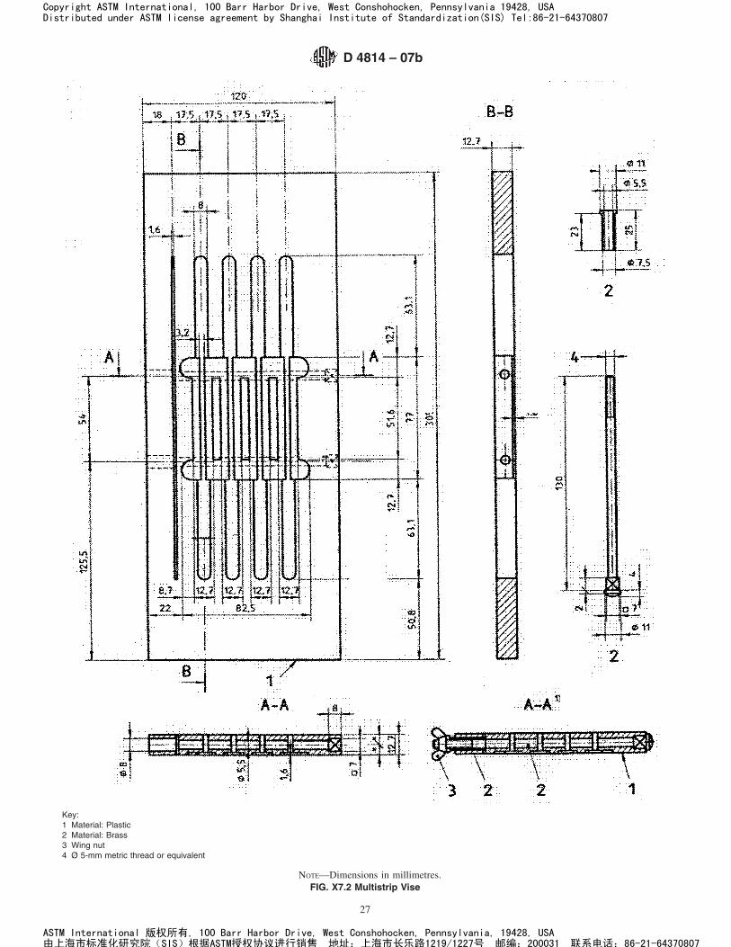
Key:1 Material: Plastic2 Material: Brass3 Wing nut4 Ø 5-mm metric thread or equivalent
NOTE—Dimensions in millimetres.FIG. X7.2 Multistrip Vise
D 4814 – 07b
27
Copyright ASTM International, 100 Barr Harbor Drive, West Conshohocken, Pennsylvania 19428, USADistributed under ASTM license agreement by Shanghai Institute of Standardization(SIS) Tel:86-21-64370807
ASTM International 版权所有, 100 Barr Harbor Drive, West Conshohocken, Pennsylvania, 19428, USA由上海市标准化研究院(SIS)根据ASTM授权协议进行销售 地址:上海市长乐路1219/1227号 邮编:200031 联系电话:86-21-64370807
X8. WATER TOLERANCE OF ETHANOL BLENDS
X8.1 Water tolerance is the ability of a fuel to dissolvewater without phase separation. It is not of concern for gasolinebecause of the very low solubility of water in hydrocarbons.Water tolerance is of some concern with gasoline-ether blendsbecause of the limited solubility of ethers in water, but it is ofgreat concern for gasoline-alcohol blends because of the veryhigh solubility of alcohols in water. Blends of gasoline withlow-molecular weight alcohols generally will dissolve about0.1 to 0.7 mass percent of water under normal conditions,depending on the nature and amount of the alcohol(s) used, thespecific hydrocarbons present, and the temperature of theblend. When blends are exposed to a greater amount of waterthan they can dissolve, they separate into a lower, alcohol-richaqueous phase, the volume of which can be significantlygreater than that of the additional water, and an upper alcohol-poor hydrocarbon phase. As the lower aqueous phase can behighly corrosive to many metals and the engine cannot operateon it, such separation is very undesirable. Similarly, the upperhydrocarbon phase may no longer meet needed volatility andantiknock properties. Blends containing low-molecular weightalcohols are generally hygroscopic and can eventually absorbenough moisture from ambient air to cause separation. Theproblem of phase separation can usually be avoided if the fuelsare sufficiently water-free initially and care is taken duringdistribution to prevent contact with water. Gasoline-alcoholblends should be resistant to phase separation at the lowesttemperatures to which they are likely to be subjected, depen-dent on the time and place of their intended use, as indicated inTable X8.1. The values in Table X8.1 are the 10th percentile6–h minimum temperatures, with each reading specificallydefined as the highest temperature of the six coldest consecu-tive hourly temperature readings of a 24–h day. For Aprilthrough September (and occasionally October, and year-round
for Hawaii), Table X8.1 specifies a minimum phase separationtemperature of 10°C (50°F), even though the 10th percentile6–h minimum temperature can be higher. Use of this tempera-ture limit also reduces the risk of separation of the fuel instorage tanks where temperatures may be lower than ambient.
NOTE X8.1—The values in Table X8.1 are taken from the U.S. ArmyBelvoir Research Development and Engineering Center’s Report No. 316,entitled, “A Predictive Study for Defining Limiting Temperatures andTheir Application in Petroleum Product Specifications.” This can beobtained as Publication AD756–420 from the National Technical Infor-mation Service in Springfield, VA 22151.
X8.2 The most important factor, besides the quantity ofwater contacted, which governs the water tolerance of a fuel, isits temperature. As the temperature of the blend decreases,water tolerance decreases. Table X8.1 indicates the lowesttemperatures to which a blend is likely to be subjected,dependent on the time and place of its intended use. Someother factors that affect water tolerance are alcohol concentra-tion and aromatics content of the fuel. Water tolerance isimproved as both alcohol and aromatics contents increase.
X8.3 With some gasoline-oxygenate blends, formation of ahaze may occur when filling a storage tank that contains waterbottoms, while commingling of gasoline-oxygenate blendswith gasoline, or when a sufficient decrease in temperatureoccurs. However, the haze may not be stable and the fuel willclear usually in a short period of time.
X8.4 A more critical water tolerance concern is the poten-tial increase in storage tank water bottoms. This can occurwhen some gasoline-oxygenate blends and gasoline-alcoholblends in particular are added to a tank that contains sufficientwater to extract some or all of the oxygenate component fromthe fuel.
D 4814 – 07b
28
Copyright ASTM International, 100 Barr Harbor Drive, West Conshohocken, Pennsylvania 19428, USADistributed under ASTM license agreement by Shanghai Institute of Standardization(SIS) Tel:86-21-64370807
ASTM International 版权所有, 100 Barr Harbor Drive, West Conshohocken, Pennsylvania, 19428, USA由上海市标准化研究院(SIS)根据ASTM授权协议进行销售 地址:上海市长乐路1219/1227号 邮编:200031 联系电话:86-21-64370807
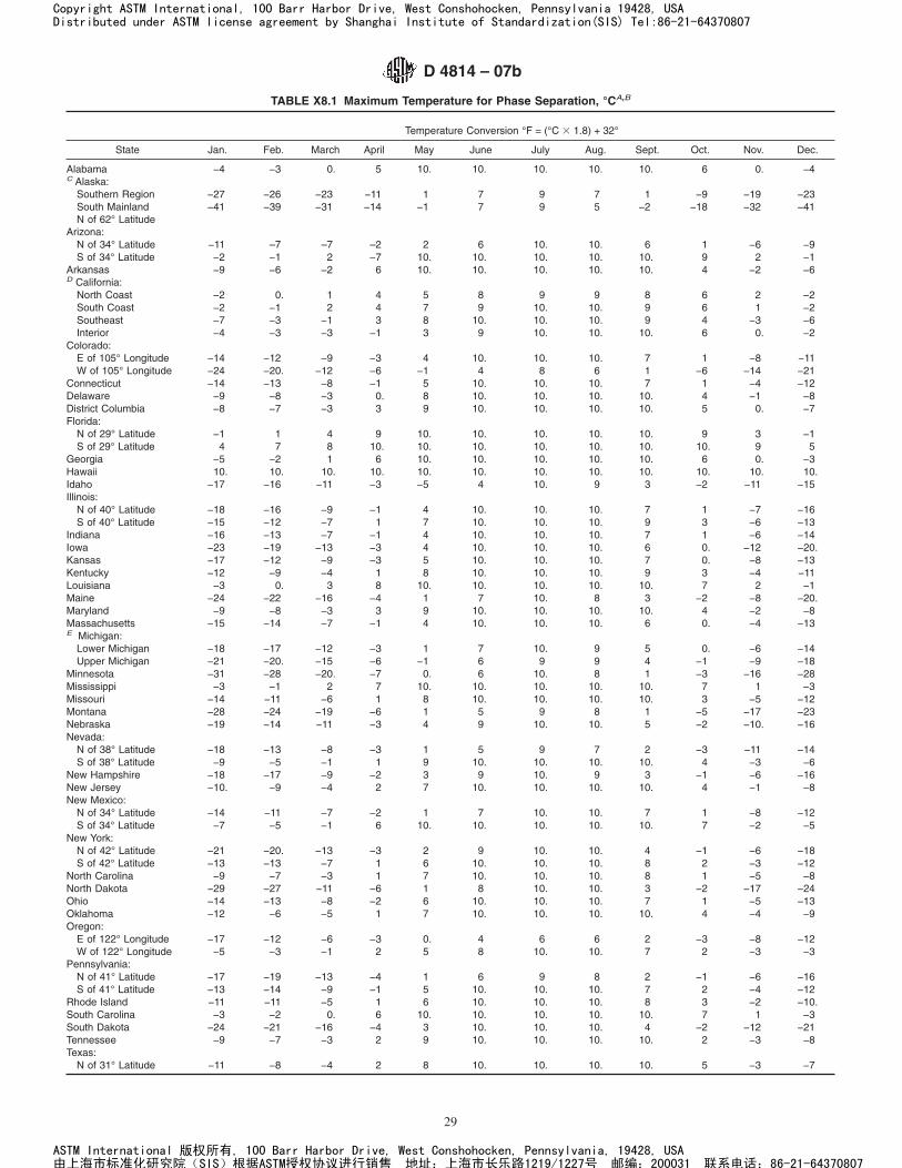
TABLE X8.1 Maximum Temperature for Phase Separation, °CA,B
Temperature Conversion °F = (°C 3 1.8) + 32°
State Jan. Feb. March April May June July Aug. Sept. Oct. Nov. Dec.
AlabamaC Alaska:
−4 −3 0. 5 10. 10. 10. 10. 10. 6 0. −4
Southern Region −27 −26 −23 −11 1 7 9 7 1 −9 −19 −23South MainlandN of 62° Latitude
Arizona:
−41 −39 −31 −14 −1 7 9 5 −2 −18 −32 −41
N of 34° Latitude −11 –7 –7 –2 2 6 10. 10. 6 1 −6 −9S of 34° Latitude −2 −1 2 −7 10. 10. 10. 10. 10. 9 2 −1
ArkansasD California:
−9 −6 −2 6 10. 10. 10. 10. 10. 4 −2 −6
North Coast −2 0. 1 4 5 8 9 9 8 6 2 −2South Coast −2 −1 2 4 7 9 10. 10. 9 6 1 −2Southeast −7 −3 −1 3 8 10. 10. 10. 9 4 −3 −6Interior −4 −3 −3 −1 3 9 10. 10. 10. 6 0. −2
Colorado:E of 105° Longitude −14 −12 −9 −3 4 10. 10. 10. 7 1 −8 −11W of 105° Longitude −24 −20. −12 −6 −1 4 8 6 1 −6 −14 −21
Connecticut −14 −13 −8 −1 5 10. 10. 10. 7 1 −4 −12Delaware −9 −8 −3 0. 8 10. 10. 10. 10. 4 −1 −8District Columbia −8 −7 −3 3 9 10. 10. 10. 10. 5 0. −7Florida:
N of 29° Latitude −1 1 4 9 10. 10. 10. 10. 10. 9 3 −1S of 29° Latitude 4 7 8 10. 10. 10. 10. 10. 10. 10. 9 5
Georgia −5 −2 1 6 10. 10. 10. 10. 10. 6 0. −3Hawaii 10. 10. 10. 10. 10. 10. 10. 10. 10. 10. 10. 10.Idaho −17 −16 −11 −3 −5 4 10. 9 3 −2 −11 −15Illinois:
N of 40° Latitude −18 −16 −9 −1 4 10. 10. 10. 7 1 −7 −16S of 40° Latitude −15 −12 −7 1 7 10. 10. 10. 9 3 −6 −13
Indiana −16 −13 −7 −1 4 10. 10. 10. 7 1 −6 −14Iowa −23 −19 −13 −3 4 10. 10. 10. 6 0. −12 −20.Kansas −17 −12 −9 −3 5 10. 10. 10. 7 0. −8 −13Kentucky −12 −9 −4 1 8 10. 10. 10. 9 3 −4 −11Louisiana −3 0. 3 8 10. 10. 10. 10. 10. 7 2 −1Maine −24 −22 −16 −4 1 7 10. 8 3 −2 −8 −20.Maryland −9 −8 −3 3 9 10. 10. 10. 10. 4 −2 −8Massachusetts −15 −14 −7 −1 4 10. 10. 10. 6 0. −4 −13E Michigan:
Lower Michigan −18 −17 −12 −3 1 7 10. 9 5 0. −6 −14Upper Michigan −21 −20. −15 −6 −1 6 9 9 4 −1 −9 −18
Minnesota −31 −28 −20. −7 0. 6 10. 8 1 −3 −16 −28Mississippi −3 −1 2 7 10. 10. 10. 10. 10. 7 1 −3Missouri −14 −11 −6 1 8 10. 10. 10. 10. 3 −5 −12Montana −28 −24 −19 −6 1 5 9 8 1 −5 −17 −23Nebraska −19 −14 −11 −3 4 9 10. 10. 5 −2 −10. −16Nevada:
N of 38° Latitude −18 −13 −8 −3 1 5 9 7 2 −3 −11 −14S of 38° Latitude −9 −5 −1 1 9 10. 10. 10. 10. 4 −3 −6
New Hampshire −18 −17 −9 −2 3 9 10. 9 3 −1 −6 −16New Jersey −10. −9 −4 2 7 10. 10. 10. 10. 4 −1 −8New Mexico:
N of 34° Latitude −14 −11 −7 −2 1 7 10. 10. 7 1 −8 −12S of 34° Latitude −7 −5 −1 6 10. 10. 10. 10. 10. 7 −2 −5
New York:N of 42° Latitude −21 −20. −13 −3 2 9 10. 10. 4 −1 −6 −18S of 42° Latitude −13 −13 −7 1 6 10. 10. 10. 8 2 −3 −12
North Carolina −9 −7 −3 1 7 10. 10. 10. 8 1 −5 −8North Dakota −29 −27 −11 −6 1 8 10. 10. 3 −2 −17 −24Ohio −14 −13 −8 −2 6 10. 10. 10. 7 1 −5 −13Oklahoma −12 −6 −5 1 7 10. 10. 10. 10. 4 −4 −9Oregon:
E of 122° Longitude −17 −12 −6 −3 0. 4 6 6 2 −3 −8 −12W of 122° Longitude
Pennsylvania:−5 −3 −1 2 5 8 10. 10. 7 2 −3 −3
N of 41° Latitude −17 −19 −13 −4 1 6 9 8 2 −1 −6 −16S of 41° Latitude −13 −14 −9 −1 5 10. 10. 10. 7 2 −4 −12
Rhode Island −11 −11 −5 1 6 10. 10. 10. 8 3 −2 −10.South Carolina −3 −2 0. 6 10. 10. 10. 10. 10. 7 1 −3South Dakota −24 −21 −16 −4 3 10. 10. 10. 4 −2 −12 −21Tennessee −9 −7 −3 2 9 10. 10. 10. 10. 2 −3 −8Texas:
N of 31° Latitude −11 −8 −4 2 8 10. 10. 10. 10. 5 −3 −7
D 4814 – 07b
29
Copyright ASTM International, 100 Barr Harbor Drive, West Conshohocken, Pennsylvania 19428, USADistributed under ASTM license agreement by Shanghai Institute of Standardization(SIS) Tel:86-21-64370807
ASTM International 版权所有, 100 Barr Harbor Drive, West Conshohocken, Pennsylvania, 19428, USA由上海市标准化研究院(SIS)根据ASTM授权协议进行销售 地址:上海市长乐路1219/1227号 邮编:200031 联系电话:86-21-64370807
SUMMARY OF CHANGES
Subcommittee D02.A0.01 has identified the location of selected changes to this standard since the last issue(D 4814–07a) that may impact the use of this standard. (Approved Dec. 1, 2007.)
(1) Revised 1.7.(2) Deleted decimal points and added footnotes to Table 1,
Table 3, and Table X8.1.(3) Revised Footnote D in Table 2.
Subcommittee D02.A0.01 has identified the location of selected changes to this standard since the last issue(D 4814–07) that may impact the use of this standard. (Approved July 15, 2007.)
(1) Removed Test Method D 2533 from the Referenced Docu-ments, 5.2.4, 7.1.2, X1.10, X2.1, and X2.5 and revised text asnecessary to refer to Test Method D 5188.(2) Removed Footnote E on water tolerance from Table 2.(3) Revised format of Table 3.(4) Removed withdrawn Test Method D 6422 from the Ref-erenced Documents, 5.7.1, and 7.1.10.
(5) Revised 5.7.1.
(6) Removed X1.17 and added Appendix X8 to discuss watertolerance issues.
(7) Changed original Table 13 to Table X8.1.
(8) Updated Michigan SIP requirement in Table 12.
(9) Corrected reference to footnote in Table 4 for Delaware.
Subcommittee D02.A0.01 has identified the location of selected changes to this standard since the last issue(D 4814–06a) that may impact the use of this standard. (Approved April 15, 2007.)
(1) Deleted Note X3.1.
Subcommittee D02.A0.01 has identified the location of selected changes to this standard since the last issue(D 4814–06) that may impact the use of this standard. (Approved Nov. 1, 2006.)
(1) Revised Footnote C in Table 1.(2) Revised 5.2.3.
(3) Revised X1.12.4.
TABLE X8.1 Continued
Temperature Conversion °F = (°C 3 1.8) + 32°
State Jan. Feb. March April May June July Aug. Sept. Oct. Nov. Dec.
S of 31° Latitude −1 1 4 10. 10. 10. 10. 10. 10. 10. 3 1Utah −15 −11 −7 −2 2 8 10. 10. 7 2 −11 −12Vermont −20. −21 −12 −2 2 9 10. 10. 5 0. −6 −17Virginia −8 −7 −3 3 9 10. 10. 10. 10. 4 −2 −7Washington:
E of 122° Longitude −13 −6 −3 1 4 7 10. 10. 7 1 −5 −7W of 122° Longitude −6 −2 −2 1 4 7 9 9 6 2 −2 −2
West Virginia −13 −12 −7 −2 4 9 10. 10. 5 −2 −7 −12Wisconsin −25 −21 −15 −3 3 8 10. 10. 5 −1 −11 −21Wyoming −23 −17 −14 −6 0. 5 10. 10. 3 −2 −13 −16
A See 1.7 for determining conformance with specification limits in this table.B A maximum phase separation temperature of 10°C (50°F) is specified, even if the 6-h 10th percentile minimum temperature for the area and month can be higher.C The designated areas of Alaska are divided as follows: Southern Region—The Aleutians, Kodiak Island, the coastal strip East of Longitude 141°, and the Alaskan
Peninsula South of Latitude 52°.South Mainland—The portion of Alaska south of Latitude 62°, except the Southern Region.North of Latitude 62°—The specification test temperature must be agreed between the vendor and purchaser having regard to equipment design, expected weather
conditions, and other relevant factors.D The designated areas of California are divided by county as follows: North Coast—Alameda, Contra Costa, Del Norte, Humbolt, Lake, Marin, Mendocino, Monterey,
Napa, San Benito, San Francisco, San Mateo, Santa Clara, Santa Cruz, Solano, Sonoma, Trinity.Interior—Lassen, Modoc, Plumas, Sierra, Siskiyou, Alpine, Amador, Butte, Calaveras, Colusa, El Dorado, Fresno, Glenn, Kern (except that portion lying east of the
Los Angles County Aqueduct), Kings, Madera, Mariposa, Merced, Placer, Sacramento, San Joaquin, Shasta, Stanislaus, Sutter, Tehama, Tulare, Tuolumne, Yolo, Yuba,Nevada.
South Coast—Orange, San Diego, San Luis Obispo, Santa Barbara, Ventura, Los Angeles (except that portion lying north of the San Gabriel Mountain range and eastof the Los Angeles County Aqueduct).
Southeast—Imperial, Riverside, San Bernardino, Los Angeles (that portion lying north of the San Gabriel Mountain range and east of the Los Angeles CountyAqueduct), Mono, Inyo, Kern (that portion lying east of the Los Angeles County Aqueduct).
E The designated areas of Michigan are divided as follows: Lower Michigan—That portion of the state lying east of Lake Michigan.Upper Michigan—That portion of the state lying north of Wisconsin and of Lake Michigan.
D 4814 – 07b
30
Copyright ASTM International, 100 Barr Harbor Drive, West Conshohocken, Pennsylvania 19428, USADistributed under ASTM license agreement by Shanghai Institute of Standardization(SIS) Tel:86-21-64370807
ASTM International 版权所有, 100 Barr Harbor Drive, West Conshohocken, Pennsylvania, 19428, USA由上海市标准化研究院(SIS)根据ASTM授权协议进行销售 地址:上海市长乐路1219/1227号 邮编:200031 联系电话:86-21-64370807
Subcommittee D02.A0.01 has identified the location of selected changes to this standard since the last issue(D 4814–04be1) that may impact the use of this standard. (Approved May 15, 2006.)
(1) Added Practices D 4057, D 4177, D 4306, D 5842, andD 5854 to the Referenced Documents and standard text.
(2) Added Section 8.(3) Corrected errors in Table 5 and Table 6.
ASTM International takes no position respecting the validity of any patent rights asserted in connection with any item mentionedin this standard. Users of this standard are expressly advised that determination of the validity of any such patent rights, and the riskof infringement of such rights, are entirely their own responsibility.
This standard is subject to revision at any time by the responsible technical committee and must be reviewed every five years andif not revised, either reapproved or withdrawn. Your comments are invited either for revision of this standard or for additional standardsand should be addressed to ASTM International Headquarters. Your comments will receive careful consideration at a meeting of theresponsible technical committee, which you may attend. If you feel that your comments have not received a fair hearing you shouldmake your views known to the ASTM Committee on Standards, at the address shown below.
This standard is copyrighted by ASTM International, 100 Barr Harbor Drive, PO Box C700, West Conshohocken, PA 19428-2959,United States. Individual reprints (single or multiple copies) of this standard may be obtained by contacting ASTM at the aboveaddress or at 610-832-9585 (phone), 610-832-9555 (fax), or [email protected] (e-mail); or through the ASTM website(www.astm.org).
D 4814 – 07b
31
Copyright ASTM International, 100 Barr Harbor Drive, West Conshohocken, Pennsylvania 19428, USADistributed under ASTM license agreement by Shanghai Institute of Standardization(SIS) Tel:86-21-64370807
ASTM International 版权所有, 100 Barr Harbor Drive, West Conshohocken, Pennsylvania, 19428, USA由上海市标准化研究院(SIS)根据ASTM授权协议进行销售 地址:上海市长乐路1219/1227号 邮编:200031 联系电话:86-21-64370807