Embed Size (px)
Citation preview
Standard Lockers – 61000 Series Single Tier Installation Instructions
Phone: 1-800-562-5377 Int’l Phone: 323-846-6700 Fax: 1-800-562-5399 Int’l Fax: 323-846-6800 www.lockers.com [email protected]
Installation instructions are provided as general guidelines. It is advised that a professional installer be consulted. Salsbury Industries assumes no product assembly or installation liability. Copyright © 2014 Salsbury Industries. All rights reserved. Page 1 of 5 3/27/14
SALSBURY INDUSTRIES 1010 East 62nd Street, Los Angeles, CA 90001-1598
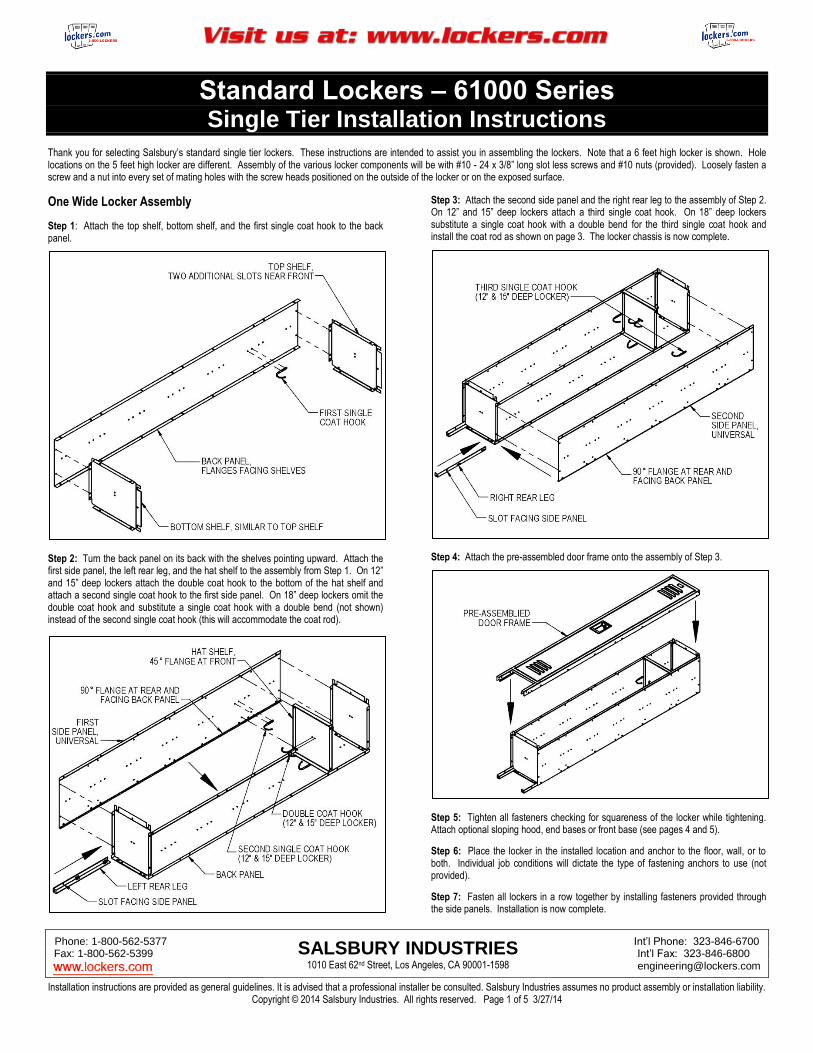
Thank you for selecting Salsbury’s standard single tier lockers. These instructions are intended to assist you in assembling the lockers. Note that a 6 feet high locker is shown. Hole locations on the 5 feet high locker are different. Assembly of the various locker components will be with #10 - 24 x 3/8” long slot less screws and #10 nuts (provided). Loosely fasten a screw and a nut into every set of mating holes with the screw heads positioned on the outside of the locker or on the exposed surface.
One Wide Locker Assembly
Step 1: Attach the top shelf, bottom shelf, and the first single coat hook to the back panel.
Step 2: Turn the back panel on its back with the shelves pointing upward. Attach the first side panel, the left rear leg, and the hat shelf to the assembly from Step 1. On 12” and 15” deep lockers attach the double coat hook to the bottom of the hat shelf and attach a second single coat hook to the first side panel. On 18” deep lockers omit the double coat hook and substitute a single coat hook with a double bend (not shown) instead of the second single coat hook (this will accommodate the coat rod).
Step 3: Attach the second side panel and the right rear leg to the assembly of Step 2. On 12” and 15” deep lockers attach a third single coat hook. On 18” deep lockers substitute a single coat hook with a double bend for the third single coat hook and install the coat rod as shown on page 3. The locker chassis is now complete.
Step 4: Attach the pre-assembled door frame onto the assembly of Step 3.
Step 5: Tighten all fasteners checking for squareness of the locker while tightening. Attach optional sloping hood, end bases or front base (see pages 4 and 5).
Step 6: Place the locker in the installed location and anchor to the floor, wall, or to both. Individual job conditions will dictate the type of fastening anchors to use (not provided).
Step 7: Fasten all lockers in a row together by installing fasteners provided through the side panels. Installation is now complete.
Standard Lockers – 61000 Series Single Tier Installation Instructions
Phone: 1-800-562-5377 Int’l Phone: 323-846-6700 Fax: 1-800-562-5399 Int’l Fax: 323-846-6800 www.lockers.com [email protected]
Installation instructions are provided as general guidelines. It is advised that a professional installer be consulted. Salsbury Industries assumes no product assembly or installation liability. Copyright © 2014 Salsbury Industries. All rights reserved. Page 2 of 5 3/27/14
SALSBURY INDUSTRIES 1010 East 62nd Street, Los Angeles, CA 90001-1598
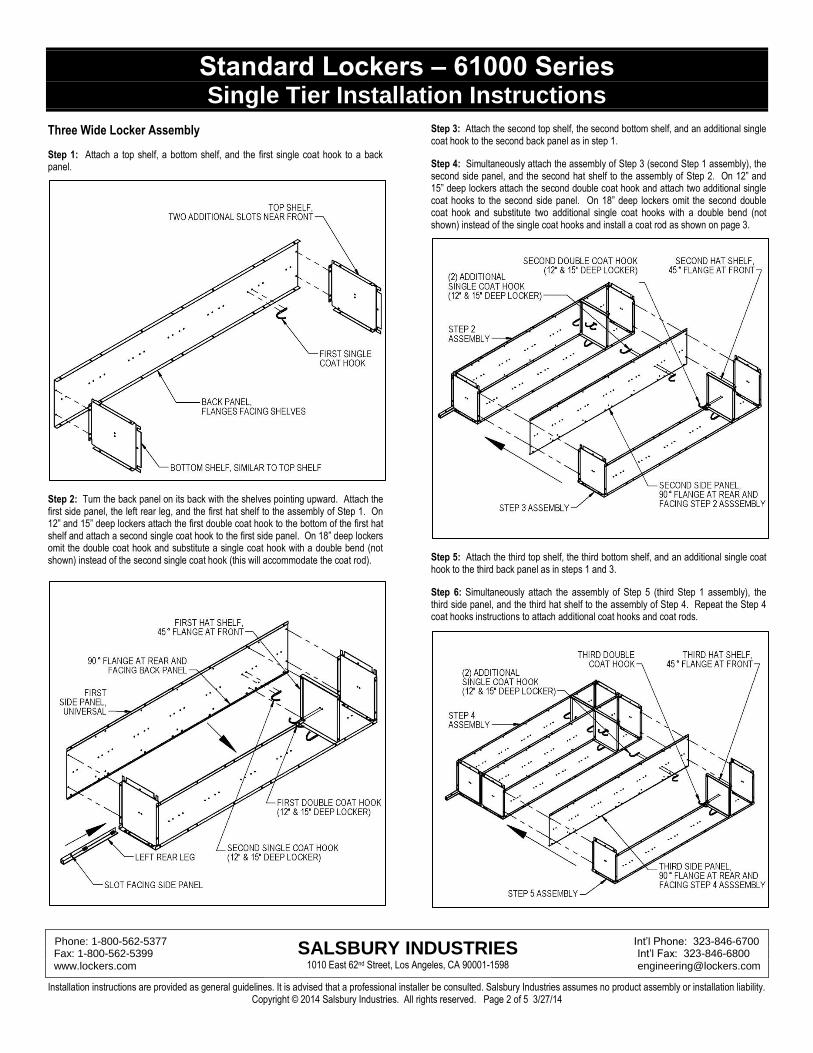
Three Wide Locker Assembly
Step 1: Attach a top shelf, a bottom shelf, and the first single coat hook to a back panel.
Step 2: Turn the back panel on its back with the shelves pointing upward. Attach the first side panel, the left rear leg, and the first hat shelf to the assembly of Step 1. On 12” and 15” deep lockers attach the first double coat hook to the bottom of the first hat shelf and attach a second single coat hook to the first side panel. On 18” deep lockers omit the double coat hook and substitute a single coat hook with a double bend (not shown) instead of the second single coat hook (this will accommodate the coat rod).
Step 3: Attach the second top shelf, the second bottom shelf, and an additional single coat hook to the second back panel as in step 1.
Step 4: Simultaneously attach the assembly of Step 3 (second Step 1 assembly), the second side panel, and the second hat shelf to the assembly of Step 2. On 12” and 15” deep lockers attach the second double coat hook and attach two additional single coat hooks to the second side panel. On 18” deep lockers omit the second double coat hook and substitute two additional single coat hooks with a double bend (not shown) instead of the single coat hooks and install a coat rod as shown on page 3.
Step 5: Attach the third top shelf, the third bottom shelf, and an additional single coat hook to the third back panel as in steps 1 and 3. Step 6: Simultaneously attach the assembly of Step 5 (third Step 1 assembly), the third side panel, and the third hat shelf to the assembly of Step 4. Repeat the Step 4 coat hooks instructions to attach additional coat hooks and coat rods.
Standard Lockers – 61000 Series Single Tier Installation Instructions
Phone: 1-800-562-5377 Int’l Phone: 323-846-6700 Fax: 1-800-562-5399 Int’l Fax: 323-846-6800 www.lockers.com [email protected]
Installation instructions are provided as general guidelines. It is advised that a professional installer be consulted. Salsbury Industries assumes no product assembly or installation liability. Copyright © 2014 Salsbury Industries. All rights reserved. Page 3 of 5 3/27/14
SALSBURY INDUSTRIES 1010 East 62nd Street, Los Angeles, CA 90001-1598
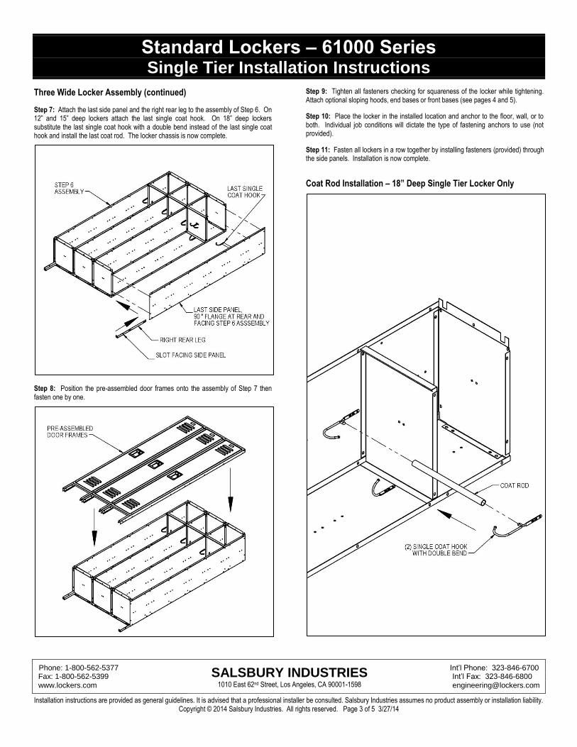
Three Wide Locker Assembly (continued)
Step 7: Attach the last side panel and the right rear leg to the assembly of Step 6. On 12” and 15” deep lockers attach the last single coat hook. On 18” deep lockers substitute the last single coat hook with a double bend instead of the last single coat hook and install the last coat rod. The locker chassis is now complete.
Step 8: Position the pre-assembled door frames onto the assembly of Step 7 then fasten one by one.
Step 9: Tighten all fasteners checking for squareness of the locker while tightening. Attach optional sloping hoods, end bases or front bases (see pages 4 and 5).
Step 10: Place the locker in the installed location and anchor to the floor, wall, or to both. Individual job conditions will dictate the type of fastening anchors to use (not provided).
Step 11: Fasten all lockers in a row together by installing fasteners (provided) through the side panels. Installation is now complete.
Coat Rod Installation – 18” Deep Single Tier Locker Only
Standard Lockers – 61000 Series Single Tier Installation Instructions
Phone: 1-800-562-5377 Int’l Phone: 323-846-6700 Fax: 1-800-562-5399 Int’l Fax: 323-846-6800 www.lockers.com [email protected]
Installation instructions are provided as general guidelines. It is advised that a professional installer be consulted. Salsbury Industries assumes no product assembly or installation liability. Copyright © 2014 Salsbury Industries. All rights reserved. Page 4 of 5 3/27/14
SALSBURY INDUSTRIES 1010 East 62nd Street, Los Angeles, CA 90001-1598
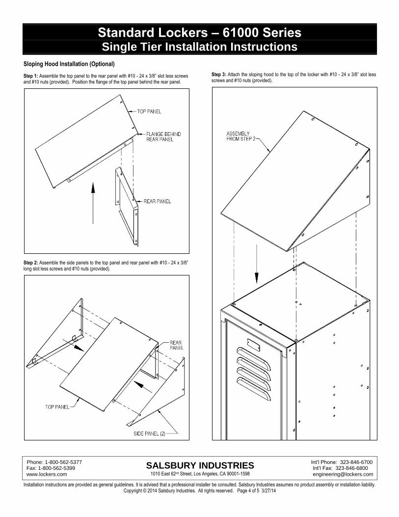
Sloping Hood Installation (Optional)
Step 1: Assemble the top panel to the rear panel with #10 - 24 x 3/8” slot less screws and #10 nuts (provided). Position the flange of the top panel behind the rear panel.
Step 2: Assemble the side panels to the top panel and rear panel with #10 - 24 x 3/8” long slot less screws and #10 nuts (provided).
Step 3: Attach the sloping hood to the top of the locker with #10 - 24 x 3/8” slot less screws and #10 nuts (provided).
Standard Lockers – 61000 Series Single Tier Installation Instructions
Phone: 1-800-562-5377 Int’l Phone: 323-846-6700 Fax: 1-800-562-5399 Int’l Fax: 323-846-6800 www.lockers.com [email protected]
Installation instructions are provided as general guidelines. It is advised that a professional installer be consulted. Salsbury Industries assumes no product assembly or installation liability. Copyright © 2014 Salsbury Industries. All rights reserved. Page 5 of 5 3/27/14
SALSBURY INDUSTRIES 1010 East 62nd Street, Los Angeles, CA 90001-1598
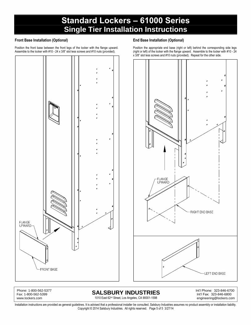
Front Base Installation (Optional)
Position the front base between the front legs of the locker with the flange upward. Assemble to the locker with #10 - 24 x 3/8” slot less screws and #10 nuts (provided).
End Base Installation (Optional)
Position the appropriate end base (right or left) behind the corresponding side legs (right or left) of the locker with the flange upward. Assemble to the locker with #10 - 24 x 3/8” slot less screws and #10 nuts (provided). Repeat for the other side.