Embed Size (px)
Citation preview
PDF generated on 16 Nov 2016DISCLAIMER : UNCONTROLLED WHEN PRINTED – PLEASE CHECK THE STATUS OF THE DOCUMENT IN IDM
Technical Specifications (In-Cash Procurement)
Diffusion Bonding - Feasibility assessment of Titanium to Stainless Steel Joints with interlayer materials
The present document is the technical specification of an R&D plan to assess the feasibility of diffusion bonded joints and record the process parameters required for production of the diffusion bonding assemblies. Joining of dissimilar materials is required to implement specific material properties in the design and to limit the use of expensive materials. Past studies of diffusion bonding have shown the diffusion bonding feasibility in specific applications. On the basis of the knowledge ...
IDM UID
SSPT33VERSION CREATED ON / VERSION / STATUS
14 Nov 2016 / 1.9 / Approved
EXTERNAL REFERENCE / VERSION

ITER_D_SSPT33
Uniaxial Diffusion Bonding
Feasibility assessment of Titanium to Stainless Steel joints with interlayer
materials
Abstract
This document specifies a R&D activity to demonstrate the feasibility of joints between different materials in the ITER ICRH Antenna vacuum transmission lines. The aim of this work is to assess the feasibility of welding of dissimilar metals by uniaxial diffusion bonding, in order to validate the manufacturing of complex assemblies requiring different material properties which are not weldable by conventional processes.

Table of Contents
Contents1 Purpose and scope of the document ..................................................................................42 Definition and acronyms ....................................................................................................43 Background .........................................................................................................................44 Joining Process ....................................................................................................................55 Objectives.............................................................................................................................56 Scope of supply....................................................................................................................67 Duration ...............................................................................................................................68 Interfaces with ITER Organization ..................................................................................69 Responsibilities....................................................................................................................610 Project monitoring ..............................................................................................................7
10.1 Control points..............................................................................................................710.2 Data management .......................................................................................................810.3 IO Reviews...................................................................................................................810.4 Monitoring and Access rights ....................................................................................810.5 Deliverables .................................................................................................................8
11 Quality Assurance...............................................................................................................911.1 General.........................................................................................................................911.2 Monitoring and Review ............................................................................................1011.3 Deviations and non-conformities .............................................................................1011.4 Documentation ..........................................................................................................10
12 R&D Activities ..................................................................................................................1013 Technical requirements ....................................................................................................11
13.1 Task 1 – Feasibility study .........................................................................................1113.1.1 Scope of the Task 1.............................................................................................1113.1.2 Definition of the R&D plan ................................................................................1113.1.3 Materials .............................................................................................................1113.1.4 Preliminary samples design ................................................................................1313.1.5 Preliminary Welding Procedure Specifications (pWPS) ....................................1313.1.6 Manufacturing of samples...................................................................................1413.1.7 NDT inspections .................................................................................................1413.1.8 Destructive tests ..................................................................................................1413.1.9 Validation of the material combination and of the WPS ....................................15
13.2 Task 2- Assessment of the compatibility with the Brazing process (Optional, in case of success of the task 1) .................................................................................................15
13.2.1 Scope of the task 2 ..............................................................................................1513.2.2 Heat treatment of the test samples ......................................................................15

ITER_D_SSTP33
3
13.2.3 NDT inspection post heat treatment ...................................................................1613.2.4 DT examination & tests post heat treatment.......................................................1613.2.5 Assessment of the brazing cycle compatibility...................................................17
13.3 Task 3 – Production of realistic samples (Optional, in case of success of the task 1) 17
13.3.1 Scope of the task 3 ..............................................................................................1713.3.2 Realistic samples design .....................................................................................1713.3.3 Manufacturing of samples...................................................................................2013.3.4 NDT inspections .................................................................................................2013.3.5 Destructive tests of the realistic samples ............................................................2113.3.6 Compatibility with brazing cycle (optional, in case of success of task 2) ..........2113.3.7 Realistic sample manufacturing evaluation ........................................................23
14 Safety requirements ..........................................................................................................2315 Reference documents ........................................................................................................23
ITER_D_SSTP33
4
1 Purpose and scope of the documentThe present document is the technical specification of an R&D plan to assess the feasibility of uniaxial diffusion bonded joints and record the process parameters required for production of the uniaxial diffusion bonding assemblies. Joining of dissimilar materials is required to implement specific material properties in the design and to limit the use of expensive materials. Past studies of uniaxial diffusion bonding have shown the diffusion bonding feasibility in specific applications.On the basis of the knowledge available to the author, this document specifies the axis of work and the associated boundaries to define the most efficient process for the ICRH application.
2 Definition and acronymsUDB: Uniaxial Diffusion BondingICRH: Ion Cyclotron Resonant HeatingRF: Radio FrequencyRVTL: Removable Vacuum Transmission lineTRO: Technical Responsible OfficerWPS: Welding Procedure SpecificationpWPS : preliminary WPSWPQR: Welding Procedure Qualification Record
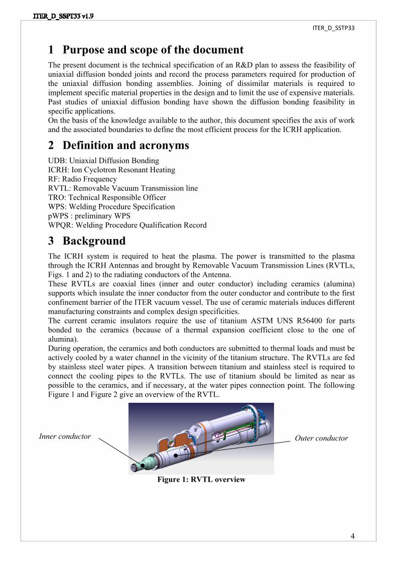
3 BackgroundThe ICRH system is required to heat the plasma. The power is transmitted to the plasma through the ICRH Antennas and brought by Removable Vacuum Transmission Lines (RVTLs, Figs. 1 and 2) to the radiating conductors of the Antenna.These RVTLs are coaxial lines (inner and outer conductor) including ceramics (alumina) supports which insulate the inner conductor from the outer conductor and contribute to the first confinement barrier of the ITER vacuum vessel. The use of ceramic materials induces different manufacturing constraints and complex design specificities.The current ceramic insulators require the use of titanium ASTM UNS R56400 for parts bonded to the ceramics (because of a thermal expansion coefficient close to the one of alumina).During operation, the ceramics and both conductors are submitted to thermal loads and must be actively cooled by a water channel in the vicinity of the titanium structure. The RVTLs are fed by stainless steel water pipes. A transition between titanium and stainless steel is required to connect the cooling pipes to the RVTLs. The use of titanium should be limited as near as possible to the ceramics, and if necessary, at the water pipes connection point. The following Figure 1 and Figure 2 give an overview of the RVTL.
Figure 1: RVTL overview
Inner conductor Outer conductor

ITER_D_SSTP33
5
Figure 2: RVTL cross section
4 Joining ProcessThe joining process to be used for this R&D is Uniaxial Diffusion Bonding (UDB). This process has been carefully selected among several welding techniques of dissimilar materials. This technique produces joints with a minimum macroscopic deformation and without deterioration in the mechanical properties of the base metals. However, significant microstructural changes occur (recrystallization, formation of intermetallic compounds) at the interface and they will determine the mechanical properties of the bond. The most influent parameters are the temperature, the pressure, and the bonding time. The process was selected on the basis of the compliance of these parameters with the properties of the base materials to be joined.A basic scheme of UDB equipment is given below:
Figure 3: UDB conventional device (for example purpose only)
5 ObjectivesThe objectives of the present task are:
- To provide a relevant R&D plan for the development of Ti-SS uniaxial diffusion bonded joints
- To develop pWPS' based on literature & previous experience.- To detail the development process including the evolution of process parameters.- To produce sets of samples representative of the joints
Ceramic insulators
Ceramic insulators
ITER_D_SSTP33
6
- To characterise the joints produced through non-destructive and destructive testing, as specified.
- To identify the best interlayer material.- To perform pertinent review of the development results- In case of acceptance, to produce the WPS (including the WPQRs) for the relevant
geometry, as specified.
6 Scope of supplyFor the scope of work:
- See chapter 13.1.1, Scope of the task 1- See chapter 13.2.1, Scope of the task 2- See chapter 13.3.1, Scope of the task 3
7 DurationThe present contract, including the option if released, shall be executed within 12 months, from the kick-off meeting date.
8 Interfaces with ITER OrganizationFace-to-face meetings shall be held at the beginning and the end of the contract (Kick-off and final meeting, organization under IO responsibility). The kick off meeting will be the starting point in the contract planning. During this meeting, the contractor will ask all necessary questions about the project, and IO will confirm all applicable document versions. During the execution of the contract, videoconference meetings shall be held to monitor the project progress. These meetings shall be organized by the contractor, who will also be responsible to maintain the meeting records (minutes, actions and decisions). The meetings will be held weekly unless otherwise agreed during the execution of the contract (for instance during procurement phase). Before the contract begins, the contractor shall provide a meeting plan, where the different meetings relevant for the good process execution will be specified.
9 ResponsibilitiesIO will carry out the monitoring of the contract.The contractor’s responsibilities include:
- Providing monthly progress reports to the IO TRO. Each report shall contain as a minimum: summary of progress since last report; updated schedule until delivery to the IO site.
- Notifying IO in accordance with the notification point specified in the MIP.- Providing if any, notification of non-conformance reports and details of outstanding
requests for information.- Ensuring that the requirements listed in the chapter 13 are fulfilled.- Procurement and acceptance of all materials to be used for the samples manufacture and
the joining process.- Execute UDB joints in the specified geometries- Performing the examinations and tests to determine the joint properties.- The report and the records of each meeting during the contract.- Shipment and delivery of the samples to ITER site

ITER_D_SSTP33
7
Requirement n° Activity Contractor IO
Task 1 – Feasibility studyRQ1.1 Delivery of QA documentation (QA & MIP) R Review &
ApprovalRQ1.2 Delivery of R&D plan R ARQ1.3 Procurement & Acceptance of materials R ARQ1.4 Production of preliminary samples design R ARQ1.5 Definition of the preliminary WPS & inspection plan R ARQ1.6 Manufacturing of preliminary samples R ARQ1.7 Performing NDT inspection R ARQ1.8 Performing DT examination & tests R ARQ1.9 Production of the End of task 1 report R A
Task 2 – Assessment of the compatibility with the brazing process (optional, in case of success of the task 1)
RQ2.1 Performing the heat treatment of the preliminary samples
R A
RQ2.2 Performing NDT inspection R ARQ2.3 Performing DT examination & tests R ARQ2.4 Production of the End of task 2 report R A
Task 3 – Production of the realistic samples (optional, in case of success of the task 1)
RQ3.2 Production of realistic samples design R ARQ3.3 Manufacturing of realistic samples R ARQ3.4 Performing NDT inspection R ARQ3.5 Performing DT examination & tests R ARQ3.6 Performing the heat treatment of the realistic samples
(optional, in case of success of the task 2)R A
RQ3.7 Performing NDT inspection of heat treated samples (optional, in case of success of the task 2)
R A
RQ3.8 Performing DT examination & tests of heat treated samples (optional, in case of success of the task 2)
R A
RQ3.9 Production of the End of task 3 report R A
Table 1: Summary of requirement, responsibilities between IO and contractorR= responsible for organizing, performing and for the content
A= Review, Comment and AcceptanceW= Witness
10 Project monitoring10.1Control points
The IO shall ensure a close oversight of the production of the Contractor and Subcontractors in accordance with accepted Manufacturing and Inspection Plans [3]. The contractor shall deliver a MIP in accordance with [3]. This monitoring shall include Control Points at critical steps in the contractor plans. The control points shall be integrated into the agreed schedule and the MIP.A Notification Point (NP) is a milestone where the contractor is required to notify the IO, that it has completed a specific task or a specific deliverable and is proceeding to the next task or to the next action on the specific deliverable. A NP is meant to enable the IO personnel to follow
ITER_D_SSTP33
8
the progress of the Contract and possibly to witness a critical manufacturing step at the contractor’s premises. The Notification shall be sent by the Contractor to the IO at least 5 working days prior to the scheduled manufacturing step. The IO shall decide whether or not they want to attend. A NP shall not affect the production flow of the contractor that shall continue the work even without a reply from the IO.A Hold Point (HP) is a milestone where the Contractor is required to notify the IO, that it has completed a specific task or a specific deliverable and must stop the associated processes until a HP Clearance is issued. The HP Clearance shall be issued on the basis of clearly identifiedQuality Control and data and Acceptance test results to be provided to the IO at the time of the request. The IO shall have a maximum of 5 working days to review the Contractors data and to notify the Contractor of its decision. In case of clearance the contractor shall resume its activity. In case of rejection, the Contractor shall develop a recovery plan that shall be submitted and reviewed by the IO within 10 working days of submission.A Witness Point (W) is a milestone which identifies an operation to be witnessed. Adequate notice shall be given to the IO, in order to allow the IO to participate to the operation.A Surveillance Point (S1) identifies an operation that requires 100% inspection.A Surveillance Point (S2) identifies an operation that requires random inspection or spot checks.Review (R) identifies a document or report to be reviewed.
10.2Data managementThe data generated during the execution of the present Contract shall be handled electronically and entered into the ITER document management system (IDM). The structure of this database is defined by IO. IO will use this database to store information related to the Contract. Data consistency checks shall be implemented to facilitate IO oversight. IO will record all deliverables issued by the contractor.
10.3IO ReviewsIO shall review the different deliverables throughout the contract progressing. IO will perform the document review within 10 working days.In case of non-acceptance by IO, or request for revision of a document (procedure, drawing…), the contractor shall submit a revised version to IO within 15 working days.
10.4Monitoring and Access rightsThe contractor shall submit monthly reports to the IO as specified in the chapter 9. In case of concerns regarding the quality of production, the IO reserves the right to perform unscheduled inspections in accordance with the ITER Procurement Quality Requirements [1].Planned and documented audits will be performed by the IO, and regulatory body representatives, to verify compliance with the technical and quality requirements of the Contract.Moreover the IO reserves the right to take photographs of the equipment used for the present purpose by the contractor during the contract life.
10.5DeliverablesIO will monitor the execution of this technical specification and the Quality Plan [2] prepared by the contractor. The quality plan [2] shall be presented to IO for review at the kick off meeting. The contractor is responsible for the quality plan update according the IO comments, and it shall be approved by IO before the beginning of the task 1 (see table 2 below).

ITER_D_SSTP33
9
The deliverables required for this technical specification shall be defined in the accepted Quality Plan [2]:
Requirement n° Activity Deliverables chapter
Task 1 – Feasibility studyRQ1.1 Quality Plan DL1.1 11.1RQ1.1 Manufacturing and Inspection Plan DL1.2 11.1&13.1.2RQ1.2 R&D plan DL1.3 13.1.2RQ1.3 Material certificate conform to EN10204 DL1.3 13.1.3RQ1.4 Preliminary sample drawings DL1.4 13.1.4RQ1.5 Preliminary WPS DL1.5 13.1.5RQ1.6 Preliminary sample manufacturing report DL1.6 13.1.6RQ1.7 NDT inspection report DL1.7 13.1.7RQ1.8 Destructive test report DL1.8 13.1.8RQ1.9 End of Task 1 report & WPS DL1.9 13.1.9
Task 2 – Assessment of the compatibility with the brazing process (optional, in case of success of the task 1)
RQ2.2 NDT inspection post heat treatment report DL2.1 13.2.3RQ2.3 Destructive test post heat treatment report DL2.2 13.2.4RQ2.4 End of Task 2 report DL2.3 13.2.5
Task 3 – Production of the realistic samples (optional, in case of success of the task 1)
RQ3.2 Realistic sample drawings DL3.2 13.3.2RQ3.3 Preliminary sample manufacturing report DL3.3 13.3.3RQ3.4 NDT inspection report DL3.4 13.3.4RQ3.5 Destructive test report DL3.5 13.3.5RQ3.7 NDT inspection post heat treatment report DL3.6 13.3.6.1RQ3.8 Destructive test post heat treatment report DL3.7 13.3.6.2RQ3.9 End of task 3 report DL3.8 13.3.7
Table 2: list of expected deliverables
11 Quality Assurance11.1General
The Contractor shall follow high standard of quality assurance (an IO approved quality program certification) and a quality assurance organisation shall be implemented as required for fabrication in nuclear and ultra-high vacuum systems.The Contractor’s QA system will be reviewed with particular reference to ITER, adjusted as appropriate and strictly applied to all stages of the supply.The general requirements are detailed in the ITER document “ITER Procurement Quality Requirements (22MFG4)” [1].Prior to commencement of the contract, a Quality Plan (22MFMW) [2] shall be submitted for IO approval giving evidence of the above and describing the organisation for this task; the skills of key workers involved in the manufacture, control, testing; any anticipated sub-contractors; and giving details of who will be the independent checker of the activities. Prior the commencement of the contract activities, a Manufacturing & Inspection Plan [3] shall be submitted for IO approval. IO will mark up any intended intervention point. MIPs are used to monitor Quality control and acceptance tests during the execution of the contract. It should be

ITER_D_SSTP33
10
noted that interventions additional to those required in this Technical Specification may be included on the MIP by IO. Note that the contractor may propose its own MIP template. In this case the template shall be submitted for IO approval.All requirements of this Technical Specification and subsequent changes proposed by the contractor during the course of execution of this Contract are subject to the Deviation Request process described in “MQP Deviations and Non-Conformities” [4].Prior to delivery of any manufactured items to the IO Site, a Release Note must be signed in accordance with the MQP Contractors Release Note (22F52F) [5].
11.2Monitoring and ReviewAudits, reviews, surveillance and inspection of the contractor's quality assurance arrangements will be carried out as required by IO appointed representatives. IO will review the Quality Plan and add inspection points at relevant activities. The contractor shall notify IO or its representative when witnessing or acceptance in relation to these is required. The Contractor shall not proceed beyond any Hold Point without obtaining authorisation from IO.
11.3Deviations and non-conformitiesAll items and services that do not meet the requirements of the contract specification shall be recorded as non-conformities using the procedure detailed in the document “Deviation and nonconformities” [4]. All non-conformances shall be recorded as part of the Contract records.
11.4DocumentationOn completion of each task specified hereafter, the contractor shall check that the documentation required by the Contract is complete in all respects.The Contractor can propose alternative Quality Assurance Documents. IO after examining them will decide if the proposed documents are acceptable.
12 R&D ActivitiesDifferent samples representative of the RVTL joints between titanium ASTM UNS56400 and stainless steel AISI 316L shall be joined and tested.The following Figure 4 gives an overview of the RF vacuum window.
Figure 4: Overview of the RVTL front WindowThe ceramic cones are joined on the metallic parts by vacuum brazing process. The material choice is decisive to match the different thermal expansions during the brazing process (840°C) and limit the tensile / compressive stress in the ceramics. As the titanium owns practically the same thermal expansion coefficient it has been decided to manufacture the window in titanium

ITER_D_SSTP33
11
ASTM UNS56400. Nevertheless, the use of titanium involves strong constraints which could have heavy financial impact on the whole RVTL design development. To limit the titanium propagation within the RVTL design, a diffusion bonded transition with stainless steel is required. For that purpose the R&D program is split in 3 tasks described hereafter.
13 Technical requirements13.1Task 1 – Feasibility study
13.1.1Scope of the Task 1The scope of the task one is to:
- Produce the R&D strategy for the whole contract, including options, and the necessary QA documentation
- Consolidate the interlayer material list- Define the samples design and drawings- Procure the necessary materials- Produce the preliminary welding procedure specification- Prepare the components of the samples- Produce the samples according the pWPS- Perform the NDT inspection of the samples joined- Perform the DT tests and examination of the samples- Estimate on the basis of the tests result which is the best material combination for the
next task.
13.1.2Definition of the R&D planThe contractor shall define a R&D plan based on all the tasks requirements specified in the present document. The contractor is free to use their own template. The contractor shall define how the task will be performed, summarize the number of samples needed to characterize the joint (when not specified in the present document) and detail the equipment used to achieve the different samples. On the basis of the realistic sample geometry specified in the task 3, the contractor shall identify if one WPS (result of the present task 1) may cover the 3 geometries, or if additional WPS have to be developed (geometry given in the task 3 have different diameters and thicknesses). As a general rule, all information useful to understand the manufacturing route shall be clearly explained within the R&D plan.In addition, the contractor shall provide a MIP (in accordance with [3]) detailing every manufacturing operation, NDT and DT inspections.The contractor shall summarize in this report the interlayer material selected, and the justification. The R&D plan shall highlight the potential sub-contractors (if any). The contractor shall propose a schedule for the task execution, and it shall be included in the R&D plan.The R&D plan shall be submitted to the IO acceptance.In addition to the R&D plan, the contractor shall produce the QA documentation specified in the chapter 11.
13.1.3 MaterialsThe contractor shall be responsible for the preparation of the material purchase specification. The Contractor shall notify the ITER Organization that the material purchase specification is complete and shall submit it to the ITER Organization acceptance. This will constitute a Hold Point (HP). Once the HP Clearance has been issued by the IO TRO, the Contractor will proceed with the purchase of the materials.

ITER_D_SSTP33
12
The material certificates type 3.1 of EN 10204:2004 conforming to chemical composition, mechanical properties, and other required properties shall be required, before the manufacture beginning. The contractor shall prepare the material purchase specifications covering the different task activities, but the contractor is free to define the material purchase strategy for the contract, in order to propose the most cost effective approach.The two base materials to be joined shall be:
- Titanium grade 5 Ti-6Al-4V ASTM UNS R56400 (ASTM standard) [8].- Stainless Steel AISI 316L(N) for which two possibilities shall be considered
a) Either Stainless steel 316L(N) (or equivalent EN grade X2CrNiMo17-12-2 controlled nitrogen, cobalt content class 2, with additional restriction on Nb and Ta impurities, resulting from radioprotection requirements).
X2CrNiMo17-12-2controlled nitrogen
Elements RCC-MR 2007 [9]max or range (wt.%)
C 0.030Mn 1.60-2.00Si 0.50P 0.030S 0.015 - (0.010)**Cr 17.00 - 18.00Ni 12.00 - 12.50Mo 2.30 - 2.70N 0.060 - 0.080Cu 1.00 - (0.3)**B 0.0020
Co* 0.05 [class 2]Nb* 0.10 - (0.01)**Ta* N/A - (0.01)**
Ta+ Nb 0.15Ti 0.10
Table 3: Chemical composition of the 316L(N) with radioprotection requirements (excluding Fe balance)
* Maximum Co is based on the Cobalt purity class 2, Nb and Ta content are based on Radioprotection requirements.
** The market availability shall be checked by the contractor with the values specified within brackets. If the material can’t be procured in relevant quantity for the project, the other values shall be specified.
This 316L(N) with radioprotection requirement shall be considered as a first possibility.b) If the market availability of the stainless steel (a) does not match the needs of
the present contract, the contractor shall instead use the AISI 316L(N) (X2CrNiMo17-12-2 controlled nitrogen, conform to RCC-MR 2007) without additional restriction, as follows:
X2CrNiMo17-12-2controlled nitrogen
Elements RCC-MR 2007 [9]max or range (wt.%)
C 0.030Mn 1.60-2.00Si 0.50P 0.030

ITER_D_SSTP33
13
S 0.015Cr 17.00 - 18.00Ni 12.00 - 12.50Mo 2.30 - 2.70N 0.060 - 0.080Cu 1.00B 0.0020Co 0.2 [class 1]
Table 4: Chemical composition of the 316L(N) (excluding Fe balance)For the interlayers, the contractor shall be also responsible for the purchase specification. The material certificates 3.1 which conform to EN 10204:2004 are required as well.Three interlayer materials shall be used to join the stainless steel to the titanium:
- A three interlayer combination of Niobium / Copper / Nickel [6]- A silver interlayer [7]- A third interlayer material to be proposed by the contractor
In any case, the material purchase specifications will be subjected to discussions between both IO and the Contractor, and may need to be modified by the Contractor.The contractor is responsible for the conformity of the stock used for the manufacture. All materials shall be free from surface cracks, fissures and any other tool marks, burns, delamination and other defects.Material identification shall be supplied with the finished samples.All remaining raw materials shall be sent back to IO after the contract completion.
13.1.4Preliminary samples designThe contractor shall propose a basic sample geometry compatible with a test program required to evaluate the joint quality. The preliminary samples shall be manufactured in accordance with available standards compatible with the test program given in the chapters 13.1.7 & 13.1.8. The contractor shall take into account that the joint shall be helium leak tested.It is important to notice that the Task 1 is necessary to validate a pWPS and produce a WPS. Thus the contractor shall take into account the geometry specified in the Task 3 to ensure the validity range of the WPS developed in the present Task 1.The contractor shall provide description of the preliminary samples design by producing the preliminary sample drawings. The drawings shall show the sample geometry, the thickness of the interlayer(s), the position of the joint.A bill of material shall be provided to IO acceptance.
13.1.5 Preliminary Welding Procedure Specifications (pWPS)The contractor shall define the preliminary welding procedure specification. The contractor shall propose a suitable pWPS format. This proposed pWPS template shall be approved by IO. This document shall be accepted by IO before starting the manufacture operations.The contractor shall specify and record in the procedure:
- The reference related to the furnace type- The Material information (geometry, dimension, chemical analysis, mechanical
properties and other useful information).- All relevant welding parameters (temperature and heating ramp up /down, applied
pressure, vacuum level, duration…)- The information (experience, certification and/or qualification, basic schooling…)
about the operators performing the diffusion bonding of the samples

ITER_D_SSTP33
14
- The information about the pre or post-welds heat treatment (T°, duration…)- The information about the surface preparation method.- The information about the assembly with the welding fixture (method, detail of fixtures
and backstops).- Any optional devices.
The contractor shall provide as pre-manufacturing documentation the procedures of the NDT and destructive tests as specified in the chapter 13.1.7 & 13.1.8. The contractor shall propose methodology for each type of test.
13.1.6 Manufacturing of samplesAfter acceptance of the preliminary procedure, the contractor shall manufacture the preliminary samples (a sample includes 2 base materials, plus the interlayer). The definitive number of samples shall be consolidated in order to cover all type of tests specified in the chapters 13.1.7 & 13.1.8 and the task 2.These preliminary samples shall be used to select the best interlayer material and the main process parameters.This phase shall be used to adapt the diffusion bonding process parameters. The contractor shall detail in a report the result of the different material joining.
13.1.7 NDT inspectionsThe contractor shall define a NDT’s examination, inspection and testing plan to check the joint quality of each sample. As general rules, if a test standard is available, it shall be followed. The NDT inspection phase shall include:
- Visual inspections of the samples- Dimensional inspections.- Dye penetrant testing (the compatibility with vacuum environment shall be validated by
IO)- 100% Radiographic testing.- Helium leak testing.
The acceptance criteria shall be discussed case by case with the IO TRO. The aim is to identify which are the acceptable/unacceptable defaults (tolerances). For that purpose the contractor shall use the ISO 5817, welding quality level B (not directly applicable, but to be transposed for UDB joint).The contractor shall supply a test report at the end of the inspections.
13.1.8Destructive testsThe contractor shall define a destructive test plan to check the joint quality of each set of sample at room temperature.The destructive test and examination plan shall include at least:
- Cross weld tensile test at room temperature- Bending tests at room temperature- Hardness test of the joint (in this case of bi-material joint, the hardness range will be
validated between IO and the contractor).- Charpy tests at room temperature- Micro/macroscopic examination The result of the metallographic examination shall be accurately detailed and shall include at least:- Type of micro structure.- Interface.- Lack of bond.- Inclusions and defects.
ITER_D_SSTP33
15
The tests equipment calibration certificates shall be included in the destructive test report.The contractor shall provide a destructive test report and the results shall be recorded.The acceptance criteria shall be discussed case by case with the IO TRO. The aim is to identify which are the acceptable/unacceptable defaults and tolerances. For that purpose the contractor shall use the ISO 5817, welding quality level B (not directly applicable, but to be transposed for UDB joint).The contractor shall supply a test report at the end of the inspections.
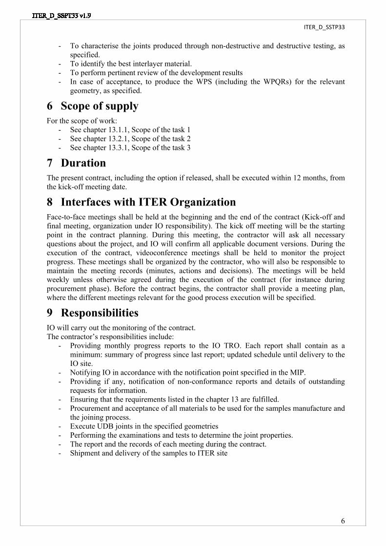
13.1.9 Validation of the material combination and of the WPSThe contractor quality plan shall include a hold point at the end of this phase. Result of this phase is decisive to validate the concept and to allow the beginning of the following tasks. Based on the test result of the task 1, the contractor shall consolidate the pWPS and provide the WPS (the WPQR shall be joined to the WPS, including all test results). The consolidate WPS and the WPQR shall be produced within an IO approved template (on the basis of the pWPS template developed and approved in the chapter 13.1.5.The contractor shall ensure that validity range of the WPS is compatible with the realistic sample geometry as specified in the chapter 3 (compatibility with different dimension and thickness).The contractor shall provide an “End task 1 report” detailing the activities performed and recording all deliverables produced during the task 1. This report shall be submitted to the IO acceptance. IO shall decide if the result are convincing and shall give its acceptance to continue the process. This step shall be highlighted as a Hold Point in the MIP [3].
13.2 Task 2- Assessment of the compatibility with the Brazing process (Optional, in case of success of the task 1)
13.2.1Scope of the task 2Validation of the task 1 result is mandatory to perform the task 2. The preliminary samples validated in the task 1 shall be used in the present task 2.The aim of this task 2 is to estimate the impact of a High Vacuum Brazing cycle on the joint property. An option in the Window design is to include the Bi material part in the window assembly before the brazing process. The scope of this task is:
- Perform a heat treatment of the sample compliant with a HV brazing cycle- Perform the NDT inspections of the samples after the brazing cycle- Perform the DT examination and tests of the samples- To compare with the task1 result and to validate (or not) the feasibility
13.2.2Heat treatment of the test samplesThe contractor shall perform a heat treatment of the samples. The aim is to reproduce a high vacuum brazing cycle to assess if the bi-material may survive to a brazing cycle, since this provide relevant information for the future RF Vacuum Window assemblies sequence.The proposed furnace run chart to be applied is the following one:
ITER_D_SSTP33
16
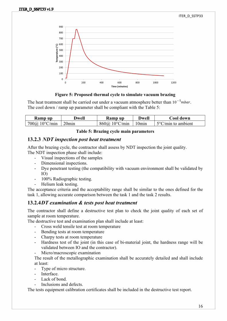
Figure 5: Proposed thermal cycle to simulate vacuum brazingThe heat treatment shall be carried out under a vacuum atmosphere better than .10 ‒ 5𝑚𝑏𝑎𝑟The cool down / ramp up parameter shall be compliant with the Table 5:
Ramp up Dwell Ramp up Dwell Cool down700@ 10°C/min 20min 860@ 10°C/min 10min 5°C/min to ambient
Table 5: Brazing cycle main parameters
13.2.3 NDT inspection post heat treatmentAfter the brazing cycle, the contractor shall assess by NDT inspection the joint quality.The NDT inspection phase shall include:
- Visual inspections of the samples- Dimensional inspections.- Dye penetrant testing (the compatibility with vacuum environment shall be validated by
IO)- 100% Radiographic testing.- Helium leak testing.
The acceptance criteria and the acceptability range shall be similar to the ones defined for the task 1, allowing accurate comparison between the task 1 and the task 2 results.
13.2.4DT examination & tests post heat treatmentThe contractor shall define a destructive test plan to check the joint quality of each set of sample at room temperature.The destructive test and examination plan shall include at least:
- Cross weld tensile test at room temperature- Bending tests at room temperature- Charpy tests at room temperature- Hardness test of the joint (in this case of bi-material joint, the hardness range will be
validated between IO and the contractor).- Micro/macroscopic examination The result of the metallographic examination shall be accurately detailed and shall include at least:- Type of micro structure.- Interface.- Lack of bond.- Inclusions and defects.
The tests equipment calibration certificates shall be included in the destructive test report.
ITER_D_SSTP33
17
The acceptance criteria and the acceptability range shall be similar to the ones defined for the task 1, allowing accurate comparison between the task 1 and the task 2 results.
13.2.5 Assessment of the brazing cycle compatibilityThe contractor quality plan shall include a hold point at the end of this phase. Result of this phase is decisive to validate the concept and to allow the assessment on realistic sample geometries.Based on the test result of the task 2, the contractor shall provide an “End task 2 report” detailing the activities performed and recording all deliverables produced during the task 2. This report shall be submitted to the IO acceptance. IO shall decide if the result are convincing and shall give its acceptance to continue the process. This step shall be highlighted as a Hold Point in the MIP [3].
13.3Task 3 – Production of realistic samples (Optional, in case of success of the task 1)
13.3.1 Scope of the task 3Validation of the task 1 result is mandatory to initiate the task 3. The WPS parameters defined shall be used in the present task to join new sets of sample, realistic to the RVTL geometry. It is necessary to identify if the sample scaling has an effect on the joining parameters.The scope of this task is to:
- Produce realistic sample design based on the RVTL geometry- Manufacture the realistic sample geometry in accordance with the validated WPS
(defined in the task 1)- Perform the NDT inspection of these realistic samples- Perform the DT examination and tests of the realistic samples- Compare the result with the task 1- Validate the WPS applicability to different samples and joint thickness.
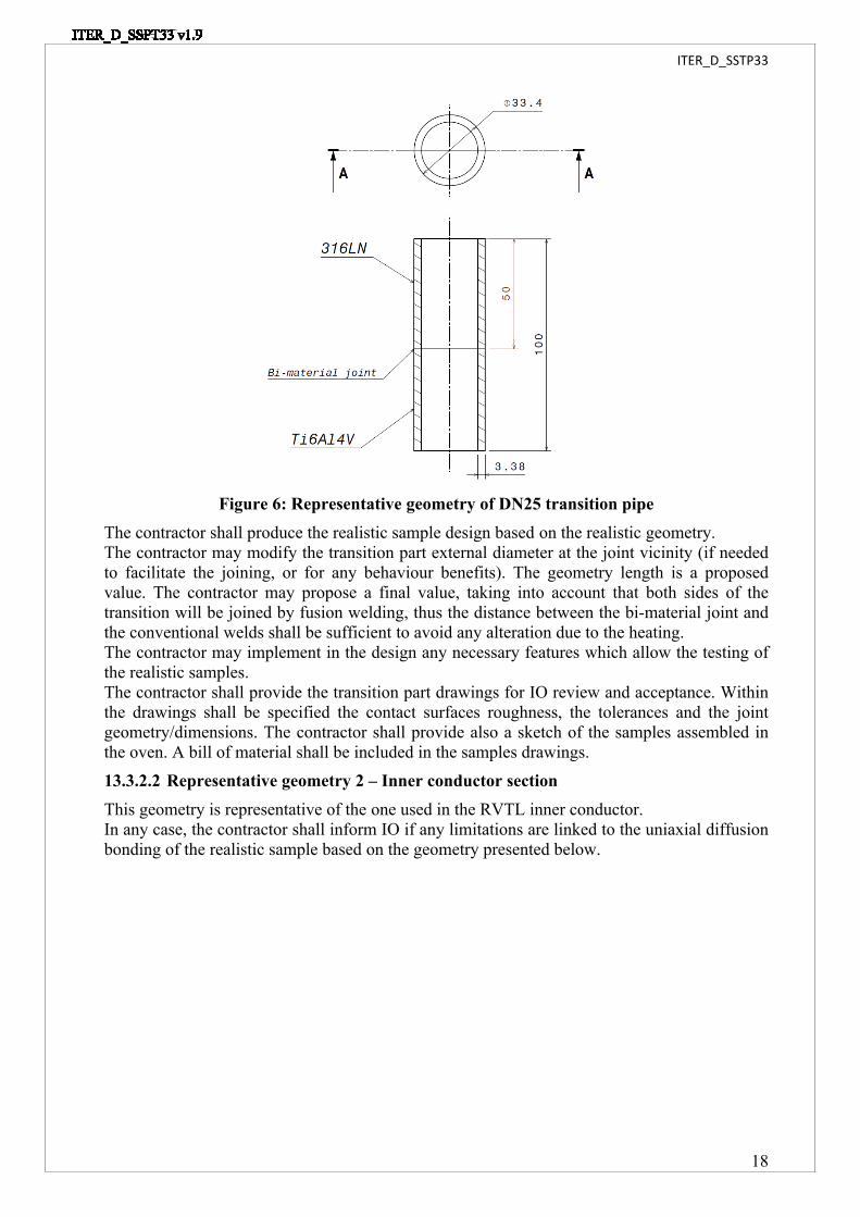
13.3.2Realistic samples designThree types of realistic sample shall be designed by the contractor. The realistic sample shall be representative of the three geometries specified in the following chapter.13.3.2.1 Representative geometry 1 – DN25 pipe sectionThis geometry is representative of the one used in the RVTL piping design.In any case, the contractor shall inform IO if any limitations are linked to the uniaxial diffusion bonding of the realistic sample based on the geometry presented below.
ITER_D_SSTP33
18
Figure 6: Representative geometry of DN25 transition pipeThe contractor shall produce the realistic sample design based on the realistic geometry.The contractor may modify the transition part external diameter at the joint vicinity (if needed to facilitate the joining, or for any behaviour benefits). The geometry length is a proposed value. The contractor may propose a final value, taking into account that both sides of the transition will be joined by fusion welding, thus the distance between the bi-material joint and the conventional welds shall be sufficient to avoid any alteration due to the heating.The contractor may implement in the design any necessary features which allow the testing of the realistic samples.The contractor shall provide the transition part drawings for IO review and acceptance. Within the drawings shall be specified the contact surfaces roughness, the tolerances and the joint geometry/dimensions. The contractor shall provide also a sketch of the samples assembled in the oven. A bill of material shall be included in the samples drawings.13.3.2.2 Representative geometry 2 – Inner conductor sectionThis geometry is representative of the one used in the RVTL inner conductor.In any case, the contractor shall inform IO if any limitations are linked to the uniaxial diffusion bonding of the realistic sample based on the geometry presented below.

ITER_D_SSTP33
19
Figure 7: Representative geometry of inner conductor sectionThe contractor shall produce the realistic sample design based on the realistic geometry.The contractor may modify the transition part internal diameter at the joint vicinity (if needed to facilitate the joining, or for any behaviour benefits). The geometry length is a proposed value. The contractor may propose a final value, taking into account that both sides of the transition will be joined by fusion welding, thus the distance between the bi-material joint and the conventional welds shall be sufficient to avoid any alteration due to the heating.The contractor may implement in the design any necessary features which allow the testing of the realistic samples.The contractor shall provide the transition part drawings for IO review and acceptance. Within the drawings shall be specified the contact surfaces roughness, the tolerances and the joint geometry/dimensions. The contractor shall provide also a sketch of the samples assembled in the oven. A bill of material shall be included in the samples drawings.13.3.2.3 Representative geometry 3 – Outer conductor sectionThis geometry is representative of the one used in the RVTL outer conductor.In any case, the contractor shall inform IO if any limitations are linked to the diffusion bonding of the realistic sample based on the geometry presented below.

ITER_D_SSTP33
20
Figure 8: Representative geometry of outer conductor sectionThe contractor shall produce the realistic sample design based on the realistic geometry.The contractor may modify the transition part external diameter at the joint vicinity (if needed to facilitate the joining, or for any behaviour benefits). The geometry length is a proposed value. The contractor may proposed a final value, taking into account that the sides of the transition will be joined by fusion welding, thus the distance between the bi-material joint and the conventional welds shall be sufficient to avoid any alteration due to the heating.The contractor may implement in the design the necessary features allowing test of the realistic samples.The contractor shall provide the transition part drawings for IO review and acceptance. Within the drawings shall be specified the contact surfaces roughness, the tolerances and the joint geometry/dimensions. The contractor shall provide also a sketch of the samples assembled in the oven. A bill of material shall be included in the samples drawings.
13.3.3Manufacturing of samplesThe contractor shall manufacture the realistic samples according to the validated WPS. The contractor shall propose a number of realistic samples by geometry to cover all tests specified hereafter. The contractor shall propose a number of realistic samples by geometry to cover the test plans specified in the chapter 13.3.4 & 13.3.5.The contractor shall detail in a manufacturing report the result of the different realistic samples joining.
13.3.4 NDT inspectionsThe contractor shall define a NDT’s examination, inspection and testing plan to check the joint quality of each realistic sample. The NDT inspection phase shall include:
- Visual inspections of the samples- Dimensional inspections.- Dye penetrant testing (the compatibility with vacuum environment shall be validated by
IO)- 100% Radiographic testing.- Helium leak testing.
ITER_D_SSTP33
21
The contractor shall supply a test report at the end of the inspections.Based on the previous task results, the acceptance criteria and acceptability range shall be consolidated, as follow:
- Leak rate less than .10 ‒ 10𝑃𝑎.𝑚3 𝑠- Conform to ISO 5817, welding quality level B(not directly applicable, but to be
transposed for UDB joint)The contractor shall follow for each type of defect the range of acceptability defined in the task 1. The contractor shall provide a test report at the end of the inspections.
13.3.5 Destructive tests of the realistic samplesThe contractor shall define a destructive test plan to check the joint quality (in accordance with the adapted ISO 5817 welding quality level B) of each set of sample at room temperature and at elevated temperature.The destructive test and examination plan shall include at least:
- Cross weld tensile test at room temperature & elevated temperature (250°C)- Bending tests at room temperature- Charpy tests at room temperature & elevated temperature (250°C)- Hardness test of the joint (in this case of bi-material joint, the hardness range will be
validated between IO and the contractor).- Micro/macroscopic examination The result of the metallographic examination shall be accurately detailed and shall include at least:- Type of micro structure.- Interface.- Lack of bond.- Inclusions and defects.
The tests equipment calibration certificates shall be included in the destructive test report.The acceptance criteria are;
- No interface defects- No inclusions- No cracks- Limit the peak and/or troughs in hardness (this criteria shall be specified with high
attention regarding the intermetallic phases arising at the joint interface)- No excessive distortion of the grain structure.- Limit of intermetallic phases creation (this acceptance criterion is very sensitive for
joining of dissimilar materials)- Limit carbide, oxide and nitride agglomeration in the welded zone
The contractor shall check, for each acceptance criteria, that the result is within the tolerance defined in the task 1 (in accordance with the ISO 5817).The contractor shall provide a destructive test report and the results shall be recorded.
13.3.6 Compatibility with brazing cycle (optional, in case of success of task 2)A part of the realistic samples shall be submitted to heat treatment (similar to the task 2).The contractor shall perform a heat treatment of the realistic samples. The aim is to reproduce a high vacuum brazing cycle to assess if the bi-material may survive to a brazing cycle, and compare to the task 2 results the possible deviation.The proposed furnace run chart to be applied is the following one:

ITER_D_SSTP33
22
Figure 9: Proposed thermal cycle to simulate vacuum brazingThe heat treatment shall be carried out under a vacuum atmosphere better than .10 ‒ 5𝑚𝑏𝑎𝑟The cool down / ramp up parameter shall be compliant with the Table 6:
Ramp up Dwell Ramp up Dwell Cool down700@ 10°C/min 20min 860@ 10°C/min 10min 5°C/min to ambient
Table 6: Brazing cycle main parameters13.3.6.1 NDT Inspection post heat treatmentAfter the brazing cycle, the contractor shall assess by NDT inspection the joint quality.The NDT inspection phase shall include:
- Visual inspections of the samples- Dimensional inspections.- Dye penetrant testing (the compatibility with vacuum environment shall be validated by
IO)- 100% Radiographic testing.- Helium leak testing.
The acceptance criteria are:- Leak rate less than .10 ‒ 10𝑃𝑎.𝑚3 𝑠- Conform to ISO 5817 criteria (not directly applicable, but to be transposed for UDB
joint)The acceptance criteria and the acceptability range shall be similar to the ones defined in the chapter 13.3.4.The contractor shall provide a test report at the end of the inspections. Any deviation compared to the chapter 13.3.4 results shall be recorded.13.3.6.2 DT examination and tests post heat treatmentThe contractor shall define a destructive test plan to check the joint quality of each set of sample at room temperature.The destructive test and examination plan shall include at least:
- Cross weld tensile test at room temperature- Bending tests at room temperature- Charpy tests at room temperature- Hardness test of the joint (in this case of bi-material joint, the hardness range will be
validated between IO and the contractor).- Micro/macroscopic examination The result of the metallographic examination shall be accurately detailed and shall include at least:

ITER_D_SSTP33
23
- Type of micro structure.- Interface.- Lack of bond.- Inclusions and defects.
The tests equipment calibration certificates shall be included in the destructive test report.The acceptance criteria and acceptability range shall be identical to the chapter 13.3.5 requirements.The contractor shall provide a destructive test report and the results shall be recorded. Any deviation compared to the chapter 13.3.5 results shall be recorded.
13.3.7 Realistic sample manufacturing evaluationResult of the task 3 is decisive to validate the joint feasibility of the realistic sample geometries.Based on the test result of the task 3, the contractor shall provide an “End task 3 report” detailing the activities performed and recording all deliverables produced during the task 3. This report shall be submitted to the IO acceptance.
14 Safety requirementsFor information:ITER is a Nuclear Facility identified in France by the number-INB-174 (“Installation Nucléaire de Base”).For Protection Important Components and in particular Safety Important Class components (SIC), the French Nuclear Regulation must be observed, in application of the Article 14 of the ITER Agreement.In such case the Contractors and Subcontractors are informed that:
- The Order 7th February 2012 applies to all the components important for the protection (PIC) and the activities important for the protection (PIA).
- The compliance with the INB-order must be demonstrated in the chain of external contractors.
- In application of article II.2.5.4 of the Order 7th February 2012, contracted activities for supervision purposes are also subject to a supervision done by the Nuclear Operator.
For the Protection Important Components, structures and systems of the nuclear facility, and Protection Important Activities the contractor shall ensure that a specific management system is implemented for his own activities and for the activities done by any Contractor and Subcontractor following the requirements of the Order 7th February 2012 [20]. No PIA is foreseen in the framework of this Contract. The samples produced within this Contract are not considered as PIC components.
15 Reference documents[1] ITER Procurement Quality Requirements (22MFG4) v.5.0[2] Quality Plan (22MFMW) v4.0[3] Manufacturing and Inspection Plan (22MDZD) v.3.0[4] MQP Deviations and Non Conformities (22F53X) v.6.2[5] MQP Contractors Release Note (22F52F).v.5.0[6] Li, Li, Xiong, Zhang et Raza, «Diffusion bonding titanium to stainless steel using Nb/Cu/Ni multi-interlayer,» Materials characterization 68, pp. 82-87, 2012.

ITER_D_SSTP33
24
[7] Balasubramanian, «Development of processing windows for diffusion bonding of Ti-6Al-4V titanium alloy and 304 stainless steel with silver as intermediate layer,» Transactions of Nonferrous Metals Society of China, pp. 2932-2938, 2015.[8] Titanium grade 5 Ti-6Al-4V ASTM UNS R56400 (ASTM standard)[9] Stainless Steel X2CrNiMo17-12-2 controlled nitrogen, RCC-MR 2007, Section 2: Materials, RM 3300.


![Technical Specifications (In-Cash Procurement) VALVES ...fusionforenergy.europa.eu/downloads/procurements/itercalls/572/... · [2.18] ASME B1.1-2003, “Unified Inch Screw Threads,](https://img.dokumen.tips/doc/110x75/5b5034b27f8b9a206e8e0910/technical-specifications-in-cash-procurement-valves-218-asme-b11-2003.jpg)