Embed Size (px)
Citation preview
The 2012 World Congress on Advances in Civil, Environmental, and Materials Research (ACEM’ 12)Seoul, Korea, August 26-30, 2012
Stability Analysis for a Reinforced Earth Retaining Wall with Vertical Steel Poles and Front Metal Meshes
*Yeong-Saeng Lee1) and Jun-Yeong Yoon2)
1), 2) Department of Civil Engineering, Kyonggi Univ., Suwon 443-760, Korea
ABSTRACT Reinforced earth retaining structures were introduced early in the 1990’s in Korea. Recently they were evolved to geosynthetic reinforced modular block walls. But the block walls could be cracked and destroyed easily by the differential settlements of the foundation soil and the rise of water. To overcome these deficiencies, a new method using a light steel pole as a vertical member and wire meshes as a wall retaining the backfill soil was developed. In this study, the stability of the newly developed wall was investigated by the laboratory model test, the field prototype test and the numerical analysis. 1. INTRODUCTION Since reinforced earth retaining structures were introduced early in the 1990’s in Korea, they have grown up in the form of the geosynthetic reinforced modular block wall which use the geogrid and geotextile as a reinforcing material and quickly resplaced the existing concrete retaining wall. Especially the modular block type reinforced earth structure has been proven to be economical, stable and applicable compared to the existing concrete retaining walls. So they are applied in the field increasingly day by day in Korea. But they are designed and constructed in a state the theory, the technical characteristics and the criteria are not setup so the construction errors and the resulting failure accidents are happening occasionally. The modular block type reinforced earth structure which use the reinforcing material may cause some problems such as the crack of the block and the resulting failure when the foundation soil settled differentially and the collapse due to the rapid rise of the water table, etc(Elias 2001). In spite of these problems, but the modular block type reinforced earth structures were applied widely in practice due to various advantages compared to the existing concrete retaining structures. At the same time various ideas were suggested and developed to overcome these problems(Greenwoo 1989). The reinforced earth retaining wall with light vertical steel poles and front metal meshes studied in this research is one of the improvements for the modular block type reinforced earth structure. It can be assembled to the height required in the ground at once and then erected up and planting mats or broken stones are used behind the front meshes so seeds are sown in them. In this research, to investigate the stability of the
1) Professor 2) Engineer, Mirae Geotechnical Eng. Institute
newly developed wall, the laboratory model test, the field prototype test and the numerical analysis were carried out, and then the measurements and the results of the numerical analysis were compared and analyzed. 2. CHARACTERISTICS OF THE PROPOSED REINFORCED EARTH RETAINING WALL At the present time, the modular block type reinforced earth structures are constructed as follows. First the bricks are laid and then the backfill soil is laid down and compacted and the reinforcing texture is connected to the bricks and these processes are repeated. But large horizontal stresses can be introduced in the construction process. As a result, horizontal displacements can be very large and they are accumulated as the structure stands up tall. And after the construction of the structure, vertical displacements of backfill soil can cause the tensile stresses in the connecting part to the bricks. So the bricks deviate from the vertical alignment or the reinforcing geogrid can be cut off. And the color of the concrete bricks can be changed as time goes by so the environmental circumstances could be not clean. To overcome these problems the method in this study was proposed. The reinforced earth retaining structure proposed in this research is composed of a few parts and they are explained in the following table 1. And the outline of the prototype test constructed for this research is explained approximately in the Fig. 1, Fig. 2 and Fig. 3. The height of the wall was 5.2 m. The front wall composed of metal meshes and light steel poles was assembled at once and then erected up using the supporting post and the backfill soil were laid down and compacted successively. It can be constructed on the relatively light foundation due to the light weight from the light steel poles and metal meshes. And the potbelly phenomena may not be observed due to the strong type steel pole for the bending moment. Also because the soil depth for the germinating the seeds is assured, as a result the wall can be covered with the plants. So it can be said the environmental- friendly structure. Table 1. Components of the proposed reinforced earth structure Front part Expanded metal meshes are assembled with C-type steel
poles. Seeding part Seed mats adhere to the front part or the broken stones are
laid down behind the front part. Connecting part of the reinforcing geotextile
The reinforcing geotextile is connected to the C-type steel poles with L-type connector.
Backfill part The reinforcing geotextile is laid down and backfilled. 3. LABOLATORY MODEL TEST To verify two matters concerned with the stability and the economics of the wall, a laboratory test was conducted (Chu 2005). The one is the comparison of the strength in the connecting part with the allowable tensile strength of the geogrid and the other is the suitability of the spacing between the poles and the spacing between the geogrids. The model test box(width 1,200 mm, height 600 mm, Fig. 4) was made and the front

part composed of poles(spacing=381 mm) and metal meshes was set up and the geogrid(vertical spacing=420 mm) was connected to the poles. These values were identical with the prototype field test. The Fig. 5 illustrates the outline of the model test. Here, the tensile strength test was conducted till the value of 83 kPa and at around the tensile strength of 80 kPa, the sound breaking down the geogrid was heard (Fig. 6). But the strength was greater than the long-time allowable tensile strength (=40 kPa) of the geogrid product so it could be used safely in the field. At the displacement of around 15 mm, the potbelly phenomenon was observed. None the less the fact, the structure was safe. So it can be suggested that the horizontal displacement should be less than the value of 15 mm to guarantee the stability in the sense of sight.
Fig. 1. The side view of the structure. Fig. 2. The connecting part (a detail of A)
Fig. 3. The view of the front part of the wall.
Fig. 4. The model test box. Fig. 5. Illustration of the model test.

Fig. 6. The tensile strength in the connec- ting part.
Fig. 7. The sectional view of measuring instruments
4. SLOPE STABILITY ANALYSIS To analyze the slope stability of the field prototype test wall numerically, the following parameters in the table 2 were applied. And it was assumed 10 pieces of geogrids were established, the same condition as the prototype wall. The slope stability was analyzed for the following 6 cases in the table 3. It was classified as the cases of the non-reinforcing and the reinforcing and the reinforcing case was classified as the dry and the wet conditions. In the case of the non-reinforcing, the wall cannot stand safely. In the case of the reinforcing, the computed min. F.S. was 1.66 which was greater than the criteria value of 1.3. So it could be thought the wall would be safe in the wet condition in spite of the rain infiltrating to the depth 10 m from the surface. As a result, it is concluded the wall could be safe externally in the heavy rainfall condition. Table 2. Parameters for soil materials and reinforcing materials for slope stability
Soil parameters Unit weight
(γt, kN/m3) Cohesion (c, kPa)
Friction angle (degree)
Existing ground 19.4 12.5 39.0 Broken rocks used for foundation
19.0 0 48.0
Backfill soil 21.3 1.5 37.8 Reinforcing materials
Tensile strength (kN) Coefficient of friction Width (m) Length (m)Geogrid 90 0.52* 1 4 *Coefficient of friction =2/3 tan φ 5. COMPARISON OF NUMERICAL ANALYSIS WITH FIELD MEASUREMENTS FOR THE PROPOSED REINFORCED EARTH RETAINING WALL To analyze the behavior of the wall, the measurements for the prototype test wall and numerical analysis were conducted. The measuring instruments were established as the following Fig. 7. A part of various stages and meshes of numerical analysis are

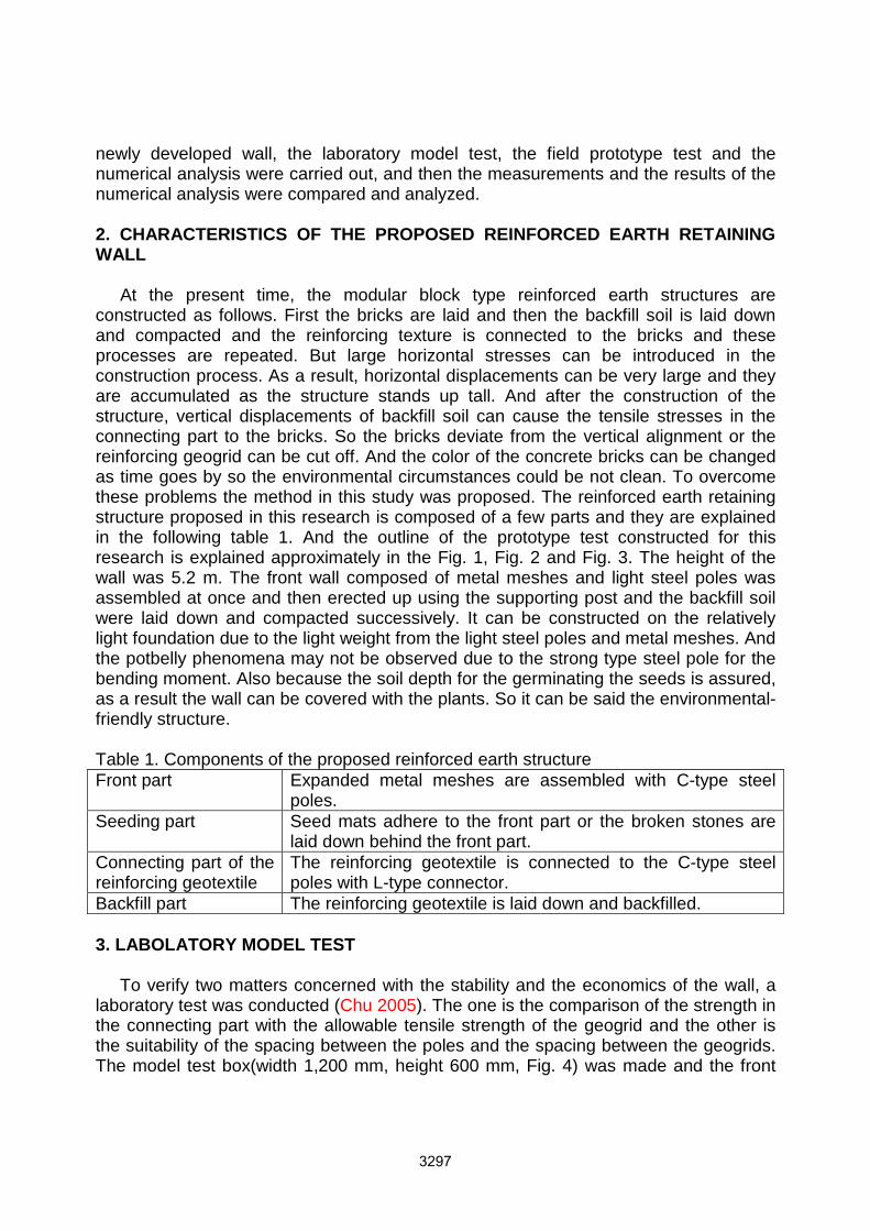
presented in the Fig. 8. The parameters in the table 4 were applied. The horizontal displacements at various heights of the wall were presented in the Fig. 9. The results of numerical analysis were at days after the completion of the wall. According to numerical analysis, the maximum horizontal displacement was 1.24 mm at the height of about 5 m. This was similar to the measuring data after 1 day from the completion of the wall. In the case of the measuring data, the data were measured continuously until 91 days after the completion of the wall. The maximum horizontal displacement was 45 mm. It could be due to the foundation composed of broken stones different from the any other concrete foundation of the block-type wall. So it may be concluded the wall totally might be pushed out outward about 33 mm. The vertical displacements were presented in the Fig. 10. The results of numerical analysis along the wall at the depth of 2 m, 4 m from the surface were similar and about 2 mm. They were similar to the measuring data after 1 day at the depth of 2 m from the surface, 2.5 mm. In the case of the measuring data, the data were measured continuously until 91 days after the completion of the wall same as the case of the horizontal displacements. The reason for the large difference between the value computed from numerical analysis and measuring data could be due to the foundation soil filled and not compacted completely, and as a result, the the backfill soil itself might settled excessively. Table 3. The results of the slope stability analysis Cases Conditions Minimum F.S.Case 1 Non-reinforcing Dry condition 0.48 Case 2
Reinforcing
Dry condition 1.95 Case 3 Wet condition (Infiltration to the depth 2 m
from the surface) 1.85
Case 4 Wet condition (Infiltration to the depth 4 m from the surface)
1.83
Case 5 Wet condition (Infiltration to the depth 6 m from the surface)
1.81
Case 6 Wet condition (Infiltration to the depth 10 m from the surface)
1.66
Table 4. Parameters for soil materials and reinforcing materials for numerical analysis
Soil parameters Young’s modulus
(E, kPa) Poisson’s ratio
Unit weight (γt, kN/m3)
Cohesion (c, kPa)
Friction angle(degree)
Existing ground 30,000 0.3 19.4 12.5 39.0 Backfill soil 30,000 0.3 21.3 1.5 37.8
Reinforcing materials, Vertical Steel Pole and Front metal Mesh Young’s modulus
(E, kPa) Poisson’s ratio
Unit weight (γt, kN/m3)
Geogrid 200,000 0.3 6 Vertical Steel Pole 21,000,000 0.3 78 Front Metal Meshes 2,100,000 0.3 78

The stresses along the geogrid at various heights were presented in the Fig. 11. The distributions of the stresses from numerical analysis and measurements were quite different. The reason might be because the strain gauges were located underneath the geogrids due to the difficulty to fix on them. According to numerical analysis, at the height of 1.91 m, the maximum tensile stress of 14.4 kPa was computed at the location of 1.2 m from the wall. Over that location, the stresses decreased gradually to about 0 kPa, and then slight compressive stresses which could be ignored worked. The horizontal pressures on the wall were presented in the Fig. 12. According to numerical analysis, the maximum horizontal pressure was about 48 kPa at the height of 0.56 m. And at the base of the wall, the pressure was 32.4 kPa about 29 % greater than the value obtained from the Rankine theory, 25.1 kPa. In the case of the measuring data, the trends of the pressure distribution were similar to the changes of the horizontal displacements till about 30 days after the completion of the wall (Fig. 9). But at the time about 34 days passed, the pressure at the about mid-height, 2.5 m was the greatest. It could be thought the backfill soil consolidated enough and then it was stabilized at those times. Similar pressure distributions have been reported by any other investigators (Fan 2009). At 53 days after the completion of the wall, the pressure was the greatest and after that time the pressure decreased a little and converged. And at the height over about 3 m, the results of numerical analysis and measuring data were similar. But the difference was great under that height, it could be thought the pressure cells were attached to the pole so the horizontal displacements of the pole were reflected on the pressures measured.
(a) Original ground (b) Establishment of front wall and backfilling
(c) First spread of geogrid (d) 10th spread of geogrid Fig. 8. Numerical meshes for reinforced wall in various stages.
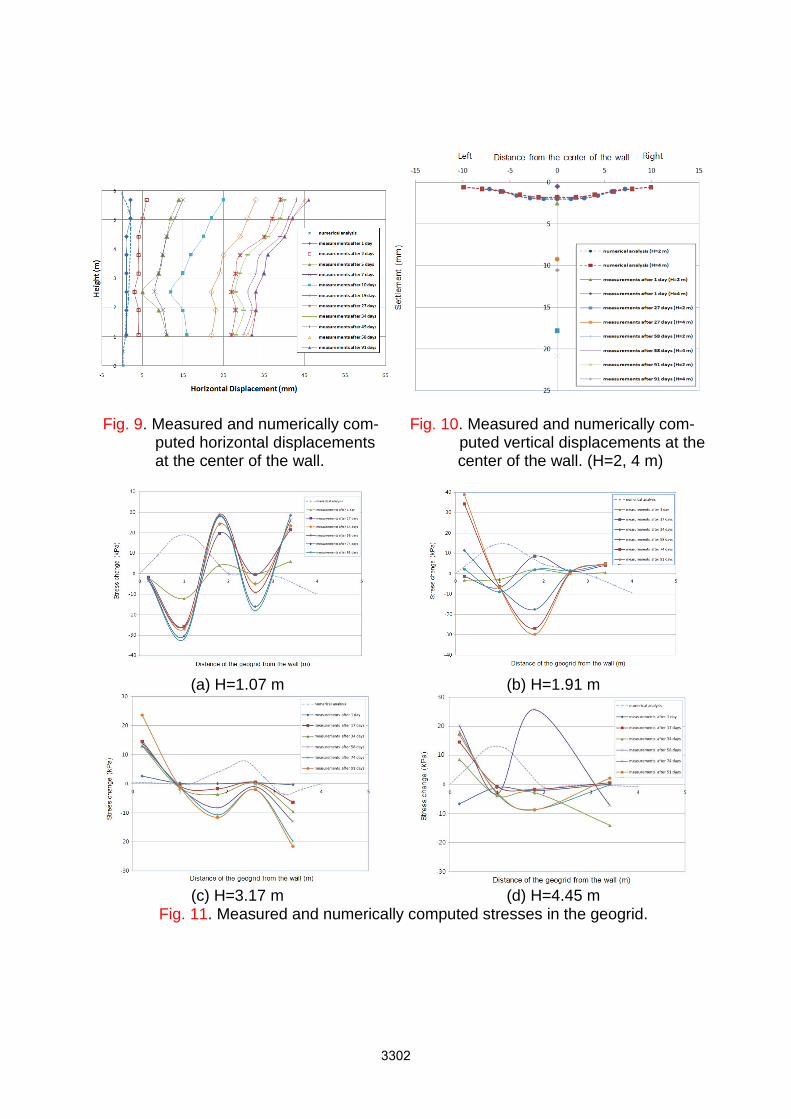
Fig. 9. Measured and numerically com- Fig. 10. Measured and numerically com- puted horizontal displacements puted vertical displacements at the at the center of the wall. center of the wall. (H=2, 4 m)
(a) H=1.07 m (b) H=1.91 m
(c) H=3.17 m (d) H=4.45 m Fig. 11. Measured and numerically computed stresses in the geogrid.
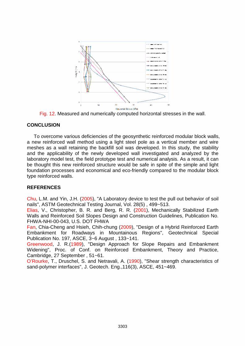
Fig. 12. Measured and numerically computed horizontal stresses in the wall.
CONCLUSION To overcome various deficiencies of the geosynthetic reinforced modular block walls, a new reinforced wall method using a light steel pole as a vertical member and wire meshes as a wall retaining the backfill soil was developed. In this study, the stability and the applicability of the newly developed wall investigated and analyzed by the laboratory model test, the field prototype test and numerical analysis. As a result, it can be thought this new reinforced structure would be safe in spite of the simple and light foundation processes and economical and eco-friendly compared to the modular block type reinforced walls. REFERENCES Chu, L.M. and Yin, J.H. (2005), "A Laboratory device to test the pull out behavior of soil nails", ASTM Geotechnical Testing Journal, Vol. 28(5) , 499~513. Elias, V., Christopher, B. R. and Berg, R. R. (2001), Mechanically Stabilized Earth Walls and Reinforced Soil Slopes Design and Construction Guidelines, Publication No. FHWA-NHI-00-043, U.S. DOT FHWA Fan, Chia-Cheng and Hsieh, Chih-chung (2009), "Design of a Hybrid Reinforced Earth Embankment for Roadways in Mountainous Regions", Geotechnical Special Publication No. 197, ASCE, 3~6 August , 133~141. Greenwood, J. R.(1989), "Design Approach for Slope Repairs and Embankment Widening", Proc. of Conf. on Reinforced Embankment, Theory and Practice, Cambridge, 27 September , 51~61. O’Rourke, T., Druschel, S. and Netravali, A. (1990), "Shear strength characteristics of sand-polymer interfaces", J. Geotech. Eng.,116(3), ASCE, 451~469.