Embed Size (px)
Citation preview
Stabalizing an Inverted Pendulum
Student: Kyle Gallagher Advisor: Robert Fersch
December 14, 2013
1 Introduction:
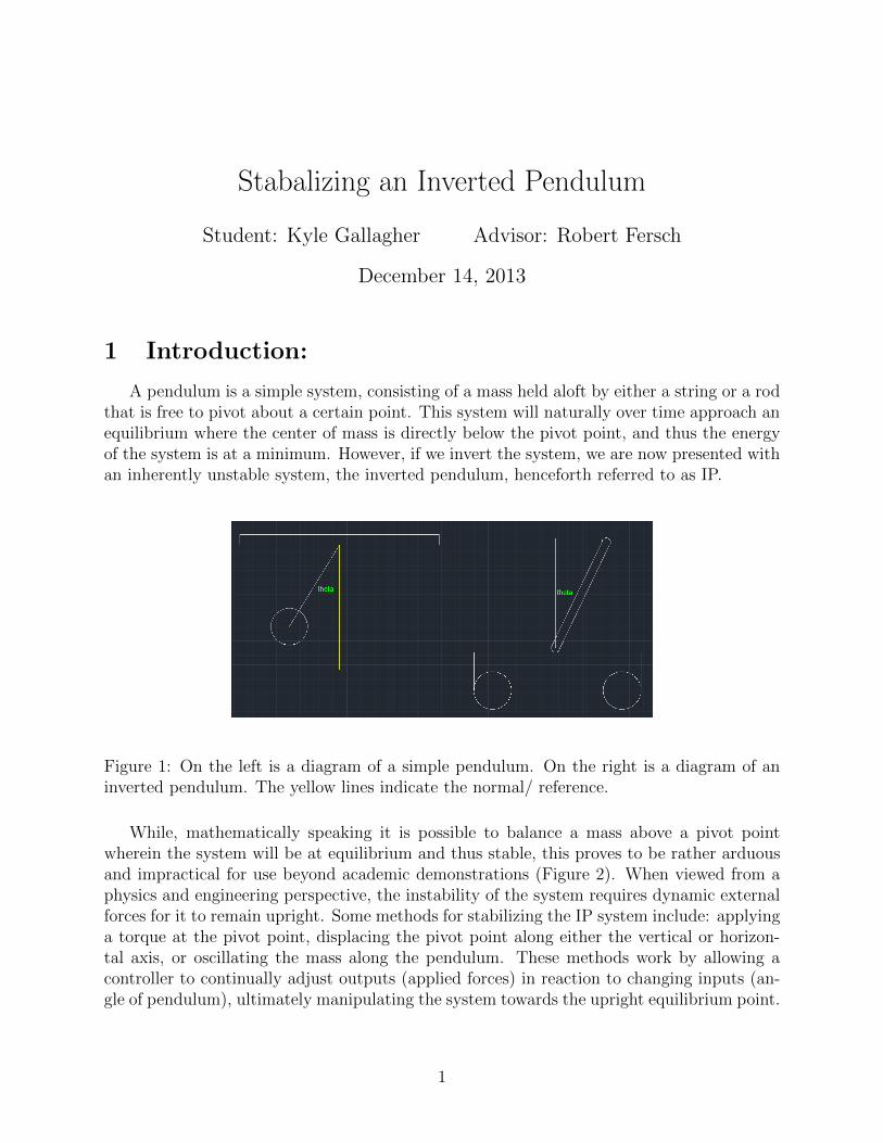
A pendulum is a simple system, consisting of a mass held aloft by either a string or a rodthat is free to pivot about a certain point. This system will naturally over time approach anequilibrium where the center of mass is directly below the pivot point, and thus the energyof the system is at a minimum. However, if we invert the system, we are now presented withan inherently unstable system, the inverted pendulum, henceforth referred to as IP.
Figure 1: On the left is a diagram of a simple pendulum. On the right is a diagram of aninverted pendulum. The yellow lines indicate the normal/ reference.
While, mathematically speaking it is possible to balance a mass above a pivot pointwherein the system will be at equilibrium and thus stable, this proves to be rather arduousand impractical for use beyond academic demonstrations (Figure 2). When viewed from aphysics and engineering perspective, the instability of the system requires dynamic externalforces for it to remain upright. Some methods for stabilizing the IP system include: applyinga torque at the pivot point, displacing the pivot point along either the vertical or horizon-tal axis, or oscillating the mass along the pendulum. These methods work by allowing acontroller to continually adjust outputs (applied forces) in reaction to changing inputs (an-gle of pendulum), ultimately manipulating the system towards the upright equilibrium point.
1
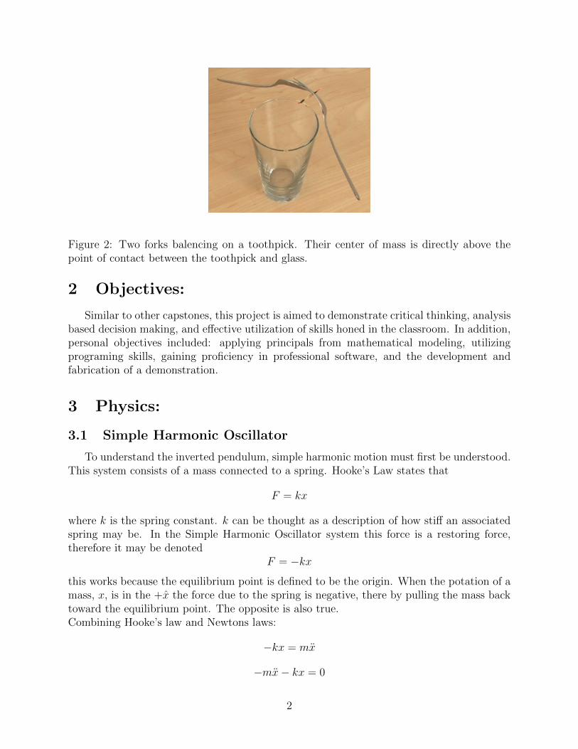
Figure 2: Two forks balencing on a toothpick. Their center of mass is directly above thepoint of contact between the toothpick and glass.
2 Objectives:
Similar to other capstones, this project is aimed to demonstrate critical thinking, analysisbased decision making, and e↵ective utilization of skills honed in the classroom. In addition,personal objectives included: applying principals from mathematical modeling, utilizingprograming skills, gaining proficiency in professional software, and the development andfabrication of a demonstration.
3 Physics:
3.1 Simple Harmonic Oscillator
To understand the inverted pendulum, simple harmonic motion must first be understood.This system consists of a mass connected to a spring. Hooke’s Law states that
F = kx
where k is the spring constant. k can be thought as a description of how sti↵ an associatedspring may be. In the Simple Harmonic Oscillator system this force is a restoring force,therefore it may be denoted
F = �kx
this works because the equilibrium point is defined to be the origin. When the potation of amass, x, is in the +x the force due to the spring is negative, there by pulling the mass backtoward the equilibrium point. The opposite is also true.Combining Hooke’s law and Newtons laws:
�kx = mx
�mx� kx = 0
2
x+k
m
x = 0
allowing !
2o
= k
m
, the equation of motion is found to be:
x+ !
2o
x = 0
This has a general solution ofx(t) = A sin(!
o
t� �)
orx(t) = A cos(!0t� �)
where, by the trigonometric co-function identities, the phase di↵erence between � and � is2⇡.
3.2 Simple Pendulum Model
In addition to understanding simple harmonic oscillations, understanding the principlesbehind simple pendulums is key to understand the underlying physics behind an invertedpendulum. A simple pendulum model is similar to that of a simple harmonic oscillator, inthat there exists a mass and there exists a restoring force that attempts to move said masstowards an equilibrium point (defined to be the origin). In the case of a simple pendulumthere exits a mass, m, attached to a string or arm of length, l attached to a pivot point.In this case, rather than a restoring force associated with a spring, the restoring force isassociated with an acceleration (gravity, g).The resistive force is that of gravity: F
g
= mg. As with any vector, this force may be splitinto its components:
F
gx
= F
g
cos ✓
F
gy
= F
g
sin ✓
since the mass is attached to a stationary pivot point, the force along the pendulum arm F
gx
is canceled out by the inherent tension. Therefore the only force of note is Fgy
. Combiningthis with newtons laws yields:
F = F
gy
sin ✓ = �mg sin ✓ = ma (1)
Since the position of the mass is with respect to the angle, ✓, it follows that the acceleration,a, of the mass is a function of the angle. We link these together through the arc-length,S,formula:
S = l✓
v = S = l✓
a = v = S = l✓
Combining this value of acceleration with (1) yields:
�mg sin ✓ = mg✓
3
�g sin ✓ = l✓
rearranging,l✓ � g sin ✓ = 0
✓ � g
l
sin ✓ = 0
By the small angle approximation, where for ✓ < 20�, the taylor expansion for sin ✓ ⇡ ✓, andfor cos ✓ ⇡ 1� ✓
2
2 . Let !2o
= g
l
then the equation of motion:
✓ � !
2o
sin ✓ = 0
whom can not be analytically solved may be expressed as
✓ � !
2o
✓ = 0
assuming the small angle approximation (✓ < 20�). This means that the simple pendulummodel described above shows simple harmonic motion.
3.3 Inverted Pendulum Model
Rather than using Newton’s law in its standard cartesian form F = ma, the polar formis used,
⌧ = I↵ = I ✓
where I is the moment of inertia around a pivot point, ⌧ is the net torque, and ↵ (or ✓)as the angular acceleration. Since the model consists of several components, to find the nettorque the net moment of inertia needs to be found.
The moment of inertia of a rod with length, l, and mass, ml
, rotating about it’s centeris given by
I
center
=ml
2
12By the parallel axis theorem,
I
center
= I
point
�mr
2
rearranging:I
center
+mr
2 = I
point
where r is the distance between the center; the moment of inertia for the rod about the itsend.:
m
l
l
2
12+m(
1
2l)2 =
m
l
l
2
12+
3ml
l
2
12=
m
l
l
2
312 l was used because that is the distance from the enter to the end (which the pendulum isallowed to rotate about).
The moment of inertia for the mass located on the pendulum, mp
, is given by:
I
mp
= m
p
r
2
4
where r is the distance away from the pivot point the center of given mass is located.
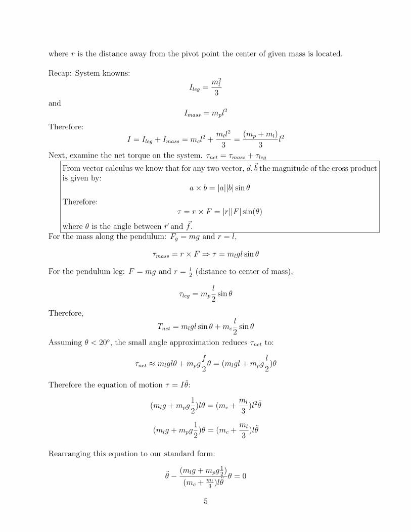
Recap: System knowns:
I
leg
=m
2l
3and
I
mass
= m
p
l
2
Therefore:
I = I
leg
+ I
mass
= m
c
l
2 +m
l
l
2
3=
(mp
+m
l
)
3l
2
Next, examine the net torque on the system. ⌧net
= ⌧
mass
+ ⌧
leg
From vector calculus we know that for any two vector, ~a,~b the magnitude of the cross productis given by:
a⇥ b = |a||b| sin ✓
Therefore:⌧ = r ⇥ F = |r||F | sin(✓)
where ✓ is the angle between ~r and ~
f .For the mass along the pendulum: F
g
= mg and r = l,
⌧
mass
= r ⇥ F ) ⌧ = m
l
gl sin ✓
For the pendulum leg: F = mg and r = l
2 (distance to center of mass),
⌧
leg
= m
p
l
2sin ✓
Therefore,
T
net
= m
l
gl sin ✓ +m
c
l
2sin ✓
Assuming ✓ < 20�, the small angle approximation reduces ⌧net
to:
⌧
net
⇡ m
l
gl✓ +m
p
g
f
2✓ = (m
l
gl +m
p
g
l
2)✓
Therefore the equation of motion ⌧ = I ✓:
(ml
g +m
p
g
1
2)l✓ = (m
c
+m
l
3)l2✓
(ml
g +m
p
g
1
2)✓ = (m
c
+m
l
3)l✓
Rearranging this equation to our standard form:
✓ �(m
l
g +m
p
g
12)
(mc
+ ml3 )l✓
✓ = 0
5
✓ � 3
2
2ml
g +m
p
g
(3mp
+m
l
)l✓ = 0
✓ � !
20✓ = 0
where
!
20 =
3
2
2ml
g +m
p
g
(3mp
+m
l
)l
4 Methods:
4.1 Model Simplifications
The following constraints were decided upon to minimize the complexity of an IP sys-tem while retaining many of the characteristics associated with it: minimize the degrees offreedom of the system and implement a system where by the controller is remote. Minimizethe degrees of freedom to one axis of travel for the cart and one axis of rotation for thependulum was favored to decrease the complexity of the system by limiting the amount ofinput data the controller received. The decision to operate the cart (base of IP system)with the controller separate was made after the development of prototype 1. During thefabrication of the first prototype it became evident that fabrication time is a function of thevolume of an object. By removing the controller (Arduino unit, motor shield, breadboard,power source) from the cart, the volume of said cart decreased substantially thus decreas-ing fabrication time while simultaneously increase the ability to manufacture prototypes asdeemed necessary through the design process.
4.2 Sensors
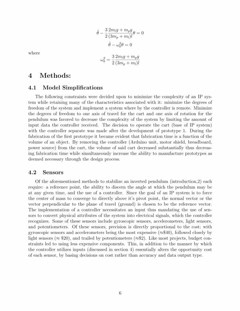
Of the aforementioned methods to stabilize an inverted pendulum (introduction,2) eachrequire: a reference point, the ability to discern the angle at which the pendulum may beat any given time, and the use of a controller. Since the goal of an IP system is to forcethe center of mass to converge to directly above it’s pivot point, the normal vector or thevector perpendicular to the plane of travel (ground) is chosen to be the reference vector.The implementation of a controller necessitates an input thus mandating the use of sen-sors to convert physical attributes of the system into electrical signals, which the controllerrecognizes. Some of these sensors include gyroscopic sensors, accelerometers, light sensors,and potentiometers. Of these sensors, precision is directly proportional to the cost; withgyroscopic sensors and accelerometers being the most expensive (⇡$40), followed closely bylight sensors (⇡ $20), and trailed by potentiometers (⇡$2). Like most projects, budget con-straints led to using less expensive components. This, in addition to the manner by whichthe controller utilizes inputs (discussed in section 4) essentially alters the opportunity costof each sensor, by basing decisions on cost rather than accuracy and data output type.
6
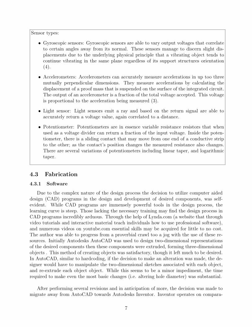
Sensor types:
• Gyroscopic sensors: Gyroscopic sensors are able to vary output voltages that correlateto certain angles away from its normal. These sensors manage to discern slight dis-placements due to the underlying physical principle that a vibrating object tends tocontinue vibrating in the same plane regardless of its support structures orientation(4).
• Accelerometers: Accelerometers can accurately measure accelerations in up too threemutually perpendicular dimensions. They measure accelerations by calculating thedisplacement of a proof mass that is suspended on the surface of the integrated circuit.The output of an accelerometer is a fraction of the total voltage accepted. This voltageis proportional to the acceleration being measured (3).
• Light sensor: Light sensors emit a ray and based on the return signal are able toaccurately return a voltage value, again correlated to a distance.
• Potentiometer: Potentiometers are in essence variable resistance resistors that whenused as a voltage divider can return a fraction of the input voltage. Inside the poten-tiometer, there is a sliding contact that may move from one end of a conductive stripto the other; as the contact’s position changes the measured resistance also changes.There are several variations of potentiometers including linear taper, and logarithmictaper.
4.3 Fabrication
4.3.1 Software
Due to the complex nature of the design process the decision to utilize computer aideddesign (CAD) programs in the design and development of desired components, was self-evident. While CAD programs are immensely powerful tools in the design process, thelearning curve is steep. Those lacking the necessary training may find the design process inCAD programs incredibly arduous. Through the help of Lynda.com (a website that throughvideo tutorials and interactive material teach individuals how to use professional software),and numerous videos on youtube.com essential skills may be acquired for little to no cost.The author was able to progress from a proverbial crawl too a jog with the use of these re-sources. Initially Autodesks AutoCAD was used to design two-dimensional representationsof the desired components then these components were extruded, forming three-dimensionalobjects . This method of creating objects was satisfactory, though it left much to be desired.In AutoCAD, similar to hardcoding, if the decision to make an alteration was made, the de-signer would have to manipulate the two-dimensional sketches associated with each object,and re-extrude each object object. While this seems to be a minor impediment, the timerequired to make even the most basic changes (i.e. altering hole diameter) was substantial.
After performing several revisions and in anticipation of more, the decision was made tomigrate away from AutoCAD towards Autodesks Inventor. Inventor operates on compara-
7
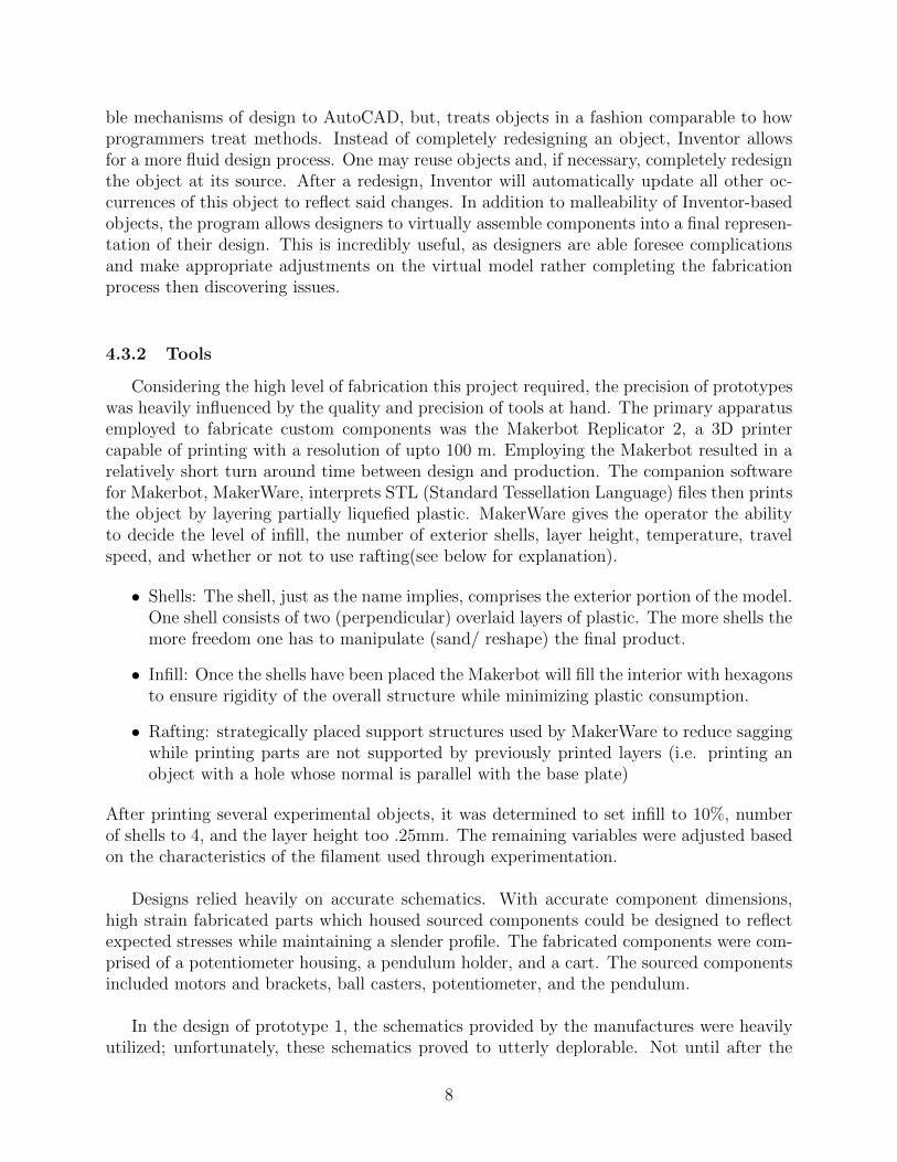
ble mechanisms of design to AutoCAD, but, treats objects in a fashion comparable to howprogrammers treat methods. Instead of completely redesigning an object, Inventor allowsfor a more fluid design process. One may reuse objects and, if necessary, completely redesignthe object at its source. After a redesign, Inventor will automatically update all other oc-currences of this object to reflect said changes. In addition to malleability of Inventor-basedobjects, the program allows designers to virtually assemble components into a final represen-tation of their design. This is incredibly useful, as designers are able foresee complicationsand make appropriate adjustments on the virtual model rather completing the fabricationprocess then discovering issues.
4.3.2 Tools
Considering the high level of fabrication this project required, the precision of prototypeswas heavily influenced by the quality and precision of tools at hand. The primary apparatusemployed to fabricate custom components was the Makerbot Replicator 2, a 3D printercapable of printing with a resolution of upto 100 m. Employing the Makerbot resulted in arelatively short turn around time between design and production. The companion softwarefor Makerbot, MakerWare, interprets STL (Standard Tessellation Language) files then printsthe object by layering partially liquefied plastic. MakerWare gives the operator the abilityto decide the level of infill, the number of exterior shells, layer height, temperature, travelspeed, and whether or not to use rafting(see below for explanation).
• Shells: The shell, just as the name implies, comprises the exterior portion of the model.One shell consists of two (perpendicular) overlaid layers of plastic. The more shells themore freedom one has to manipulate (sand/ reshape) the final product.
• Infill: Once the shells have been placed the Makerbot will fill the interior with hexagonsto ensure rigidity of the overall structure while minimizing plastic consumption.
• Rafting: strategically placed support structures used by MakerWare to reduce saggingwhile printing parts are not supported by previously printed layers (i.e. printing anobject with a hole whose normal is parallel with the base plate)
After printing several experimental objects, it was determined to set infill to 10%, numberof shells to 4, and the layer height too .25mm. The remaining variables were adjusted basedon the characteristics of the filament used through experimentation.
Designs relied heavily on accurate schematics. With accurate component dimensions,high strain fabricated parts which housed sourced components could be designed to reflectexpected stresses while maintaining a slender profile. The fabricated components were com-prised of a potentiometer housing, a pendulum holder, and a cart. The sourced componentsincluded motors and brackets, ball casters, potentiometer, and the pendulum.
In the design of prototype 1, the schematics provided by the manufactures were heavilyutilized; unfortunately, these schematics proved to utterly deplorable. Not until after the
8
fabricated components of prototype 1 were completely printed were they fitted. At thispoint the inadequate nature of the schematics was discovered. Rather than fitting togetherseamlessly, several of the sourced components were incompatible with the fabricated com-ponents. To mitigate these design flaws a Dremel rotary tool and miscellaneous files wereused to adapt already fabricated components for use with the desired sourced components.Additional errors were generated by: prior warping of the baseplate, and design imperfec-tions that stemmed from lack of previous design experience. These defects included lack offudge room for fitting fabricated components together, improperly sized holes, and warpingof larger components.
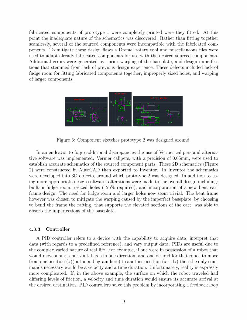
Figure 3: Component sketches prototype 2 was designed around.
In an endeavor to forgo additional discrepancies the use of Vernier calipers and alterna-tive software was implemented. Vernier calipers, with a precision of 0.05mm, were used toestablish accurate schematics of the sourced component parts. These 2D schematics (Figure2) were constructed in AutoCAD then exported to Inventor. In Inventor the schematicswere developed into 3D objects, around which prototype 2 was designed. In addition to us-ing more appropriate design software, alterations were made to the overall design including:built-in fudge room, resized holes (125% required), and incorporation of a new bent cartframe design. The need for fudge room and larger holes now seem trivial. The bent framehowever was chosen to mitigate the warping caused by the imperfect baseplate; by choosingto bend the frame the rafting, that supports the elevated sections of the cart, was able toabsorb the imperfections of the baseplate.
4.3.3 Controller
A PID controller refers to a device with the capability to acquire data, interpret thatdata (with regards to a predefined reference), and vary output data. PIDs are useful due tothe complex varied nature of real life. For example, if one were in possession of a robot thatwould move along a horizontal axis in one direction, and one desired for that robot to movefrom one position (x)(put in a diagram here) to another position (x+ dx) then the only com-mands necessary would be a velocity and a time duration. Unfortunately, reality is expresslymore complicated. If, in the above example, the surface on which the robot traveled haddi↵ering levels of friction, a velocity and time duration would ensure its accurate arrival atthe desired destination. PID controllers solve this problem by incorporating a feedback loop
9
thereby enabling an error to be calculated. This error is stored in memory and in conjunc-tion with current inputs determines an appropriate output. In terms of the robot example,the destination would be defined as the reference point. After an initial command (velocityand time duration) was executed, the error, or displacement from the reference, would becalculated and a new command would be issued. PIDs are by their design, recursive, so thisprocess will continue to iterate until no error is calculated (robot reached destination). Simi-lar to the robot example, in the IP model developed the PID controller was the Arduino unit.
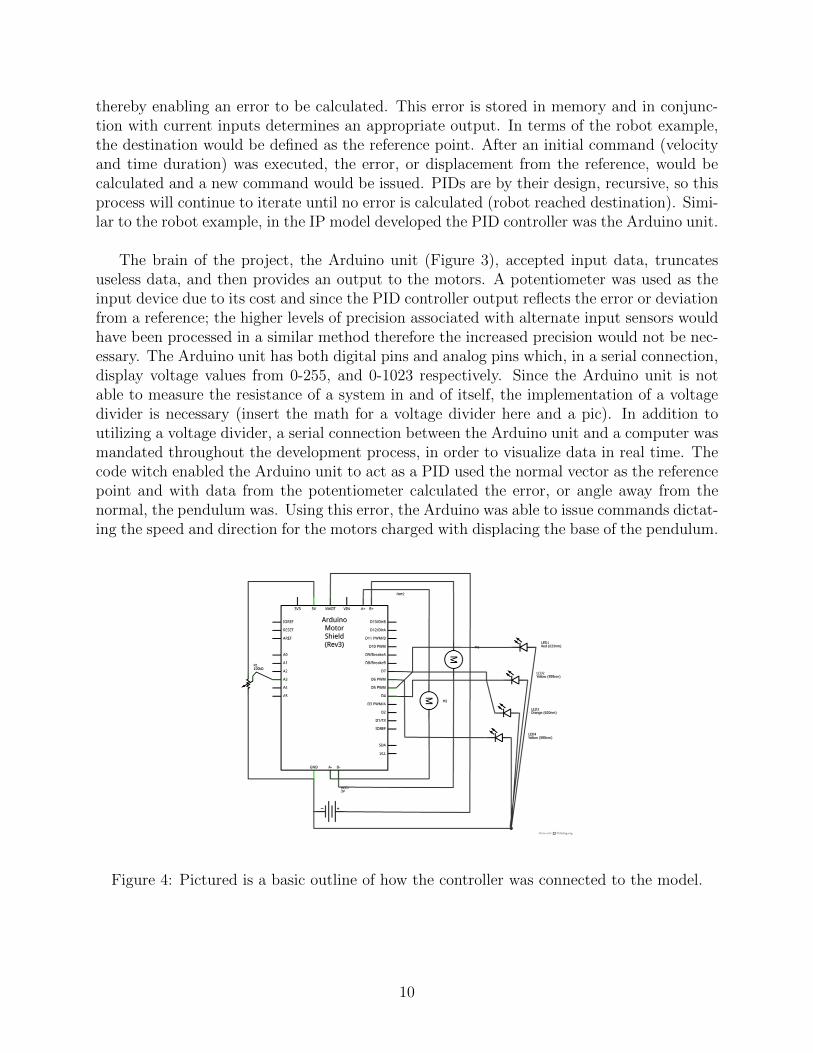
The brain of the project, the Arduino unit (Figure 3), accepted input data, truncatesuseless data, and then provides an output to the motors. A potentiometer was used as theinput device due to its cost and since the PID controller output reflects the error or deviationfrom a reference; the higher levels of precision associated with alternate input sensors wouldhave been processed in a similar method therefore the increased precision would not be nec-essary. The Arduino unit has both digital pins and analog pins which, in a serial connection,display voltage values from 0-255, and 0-1023 respectively. Since the Arduino unit is notable to measure the resistance of a system in and of itself, the implementation of a voltagedivider is necessary (insert the math for a voltage divider here and a pic). In addition toutilizing a voltage divider, a serial connection between the Arduino unit and a computer wasmandated throughout the development process, in order to visualize data in real time. Thecode witch enabled the Arduino unit to act as a PID used the normal vector as the referencepoint and with data from the potentiometer calculated the error, or angle away from thenormal, the pendulum was. Using this error, the Arduino was able to issue commands dictat-ing the speed and direction for the motors charged with displacing the base of the pendulum.
Figure 4: Pictured is a basic outline of how the controller was connected to the model.
10
5 Results:
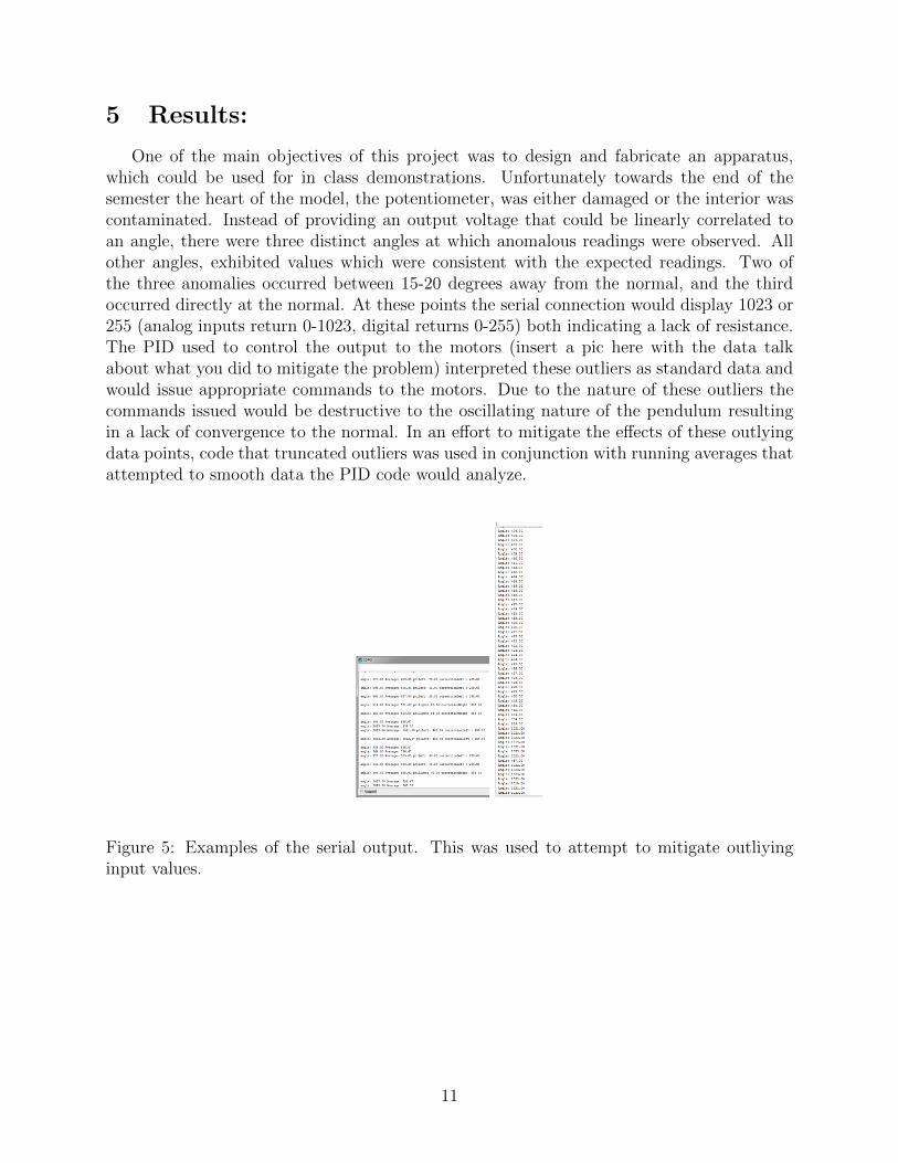
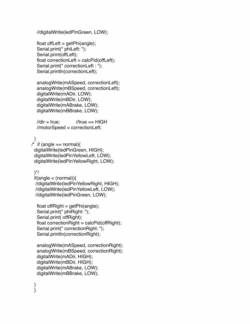
One of the main objectives of this project was to design and fabricate an apparatus,which could be used for in class demonstrations. Unfortunately towards the end of thesemester the heart of the model, the potentiometer, was either damaged or the interior wascontaminated. Instead of providing an output voltage that could be linearly correlated toan angle, there were three distinct angles at which anomalous readings were observed. Allother angles, exhibited values which were consistent with the expected readings. Two ofthe three anomalies occurred between 15-20 degrees away from the normal, and the thirdoccurred directly at the normal. At these points the serial connection would display 1023 or255 (analog inputs return 0-1023, digital returns 0-255) both indicating a lack of resistance.The PID used to control the output to the motors (insert a pic here with the data talkabout what you did to mitigate the problem) interpreted these outliers as standard data andwould issue appropriate commands to the motors. Due to the nature of these outliers thecommands issued would be destructive to the oscillating nature of the pendulum resultingin a lack of convergence to the normal. In an e↵ort to mitigate the e↵ects of these outlyingdata points, code that truncated outliers was used in conjunction with running averages thatattempted to smooth data the PID code would analyze.
Figure 5: Examples of the serial output. This was used to attempt to mitigate outliyinginput values.
11
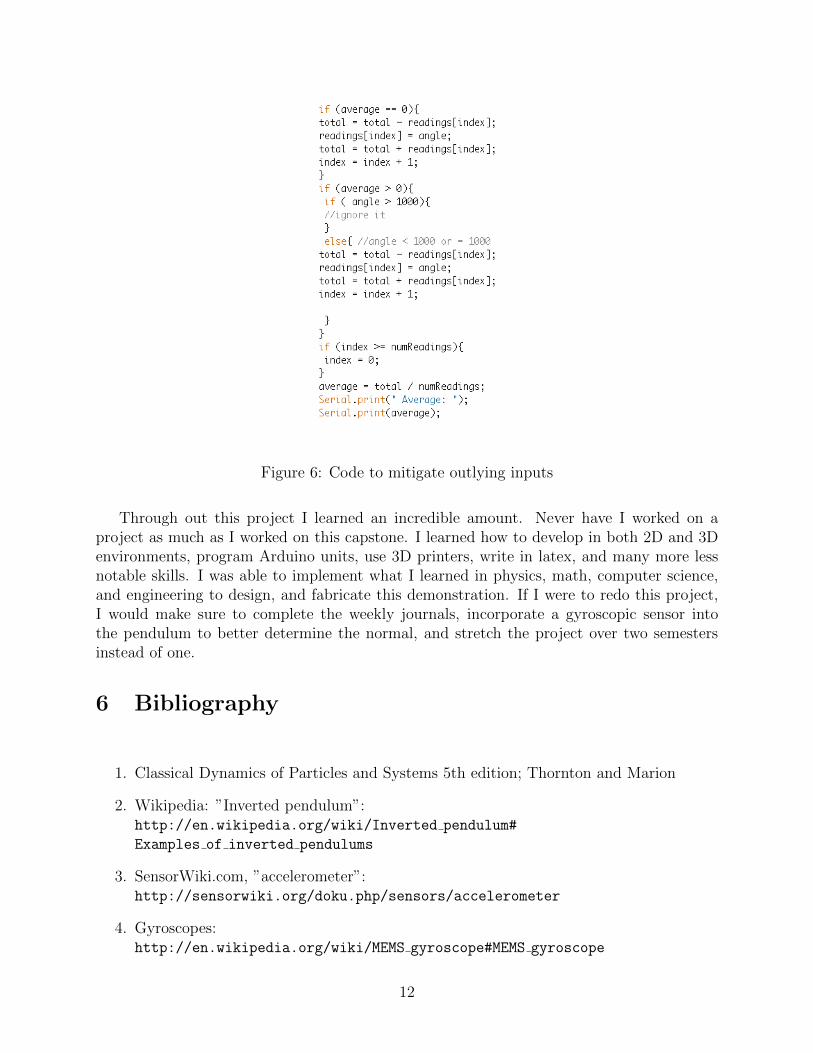
Figure 6: Code to mitigate outlying inputs
Through out this project I learned an incredible amount. Never have I worked on aproject as much as I worked on this capstone. I learned how to develop in both 2D and 3Denvironments, program Arduino units, use 3D printers, write in latex, and many more lessnotable skills. I was able to implement what I learned in physics, math, computer science,and engineering to design, and fabricate this demonstration. If I were to redo this project,I would make sure to complete the weekly journals, incorporate a gyroscopic sensor intothe pendulum to better determine the normal, and stretch the project over two semestersinstead of one.
6 Bibliography
this is red
1. Classical Dynamics of Particles and Systems 5th edition; Thornton and Marion
2. Wikipedia: ”Inverted pendulum”:http://en.wikipedia.org/wiki/Inverted pendulum#
Examples of inverted pendulums
3. SensorWiki.com, ”accelerometer”:http://sensorwiki.org/doku.php/sensors/accelerometer
4. Gyroscopes:http://en.wikipedia.org/wiki/MEMS gyroscope#MEMS gyroscope
12

5. EasyCAD for you:http://www.youtube.com/watch?v=xquI8gcdwbs
6. Lynda.com
7. Numerical Solutions to Di↵erential Equations:http://introcs.cs.princeton.edu/java/94diffeq/
8. Classical Dynamics: Taylor
13
7 Additional Diagrams:
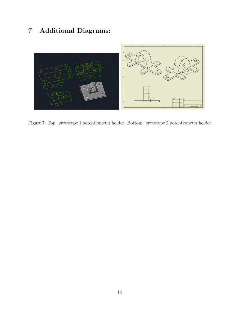
Figure 7: Top: prototype 1 potentiometer holder. Bottom: prototype 2 potentiometer holder
14
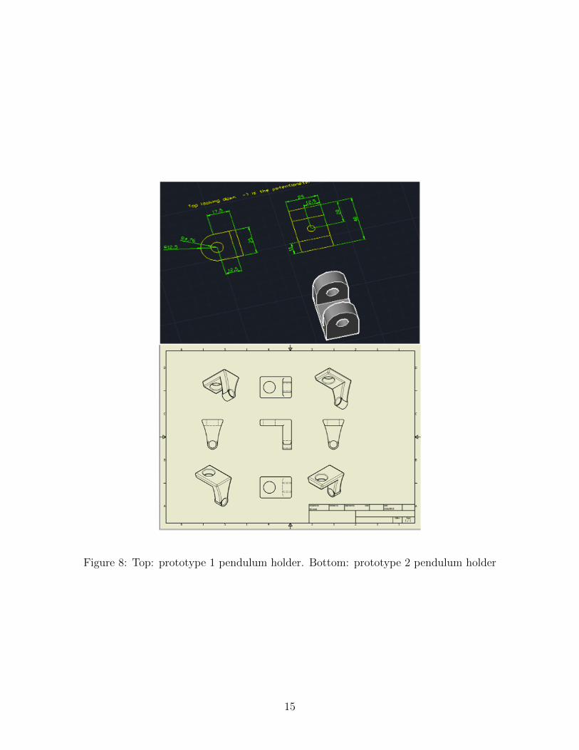
Figure 8: Top: prototype 1 pendulum holder. Bottom: prototype 2 pendulum holder
15
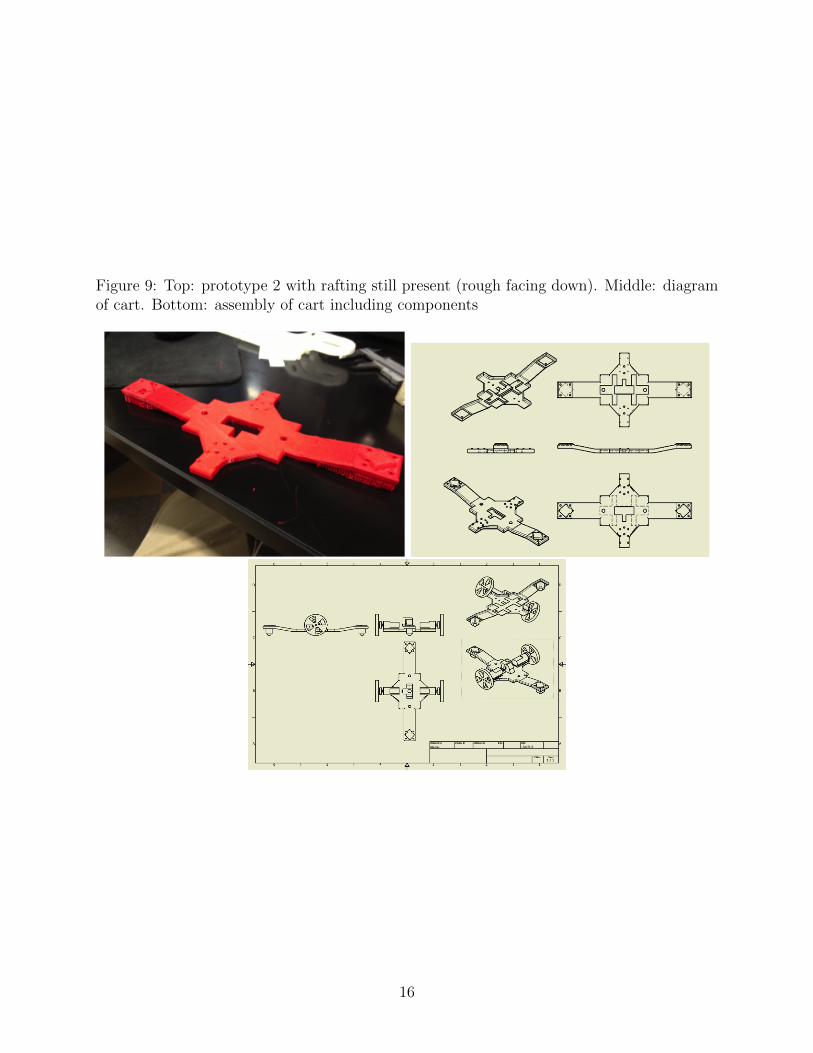
Figure 9: Top: prototype 2 with rafting still present (rough facing down). Middle: diagramof cart. Bottom: assembly of cart including components
16
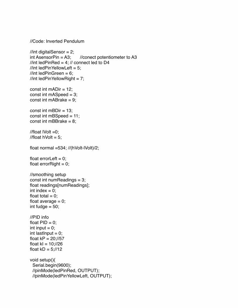
//Code: Inverted Pendulum
//int digitalSensor = 2;int AsensorPin = A3; //conect potentiometer to A3//int ledPinRed = 4; // connect led to D4//int ledPinYellowLeft = 5;//int ledPinGreen = 6;//int ledPinYellowRight = 7;
const int mADir = 12;const int mASpeed = 3;const int mABrake = 9;
const int mBDir = 13;const int mBSpeed = 11;const int mBBrake = 8;
//float lVolt =0; //float hVolt = 5;
float normal =534; //(hVolt-lVolt)/2;
float errorLeft = 0;float errorRight = 0;
//smoothing setupconst int numReadings = 3;float readings[numReadings];int index = 0;float total = 0;float average = 0;int fudge = 50;
//PID infofloat PID = 0;int input = 0;int lastInput = 0; float kP = 20;//57float kI = 10;//26float kD = 5;//12
void setup(){ Serial.begin(9600); //pinMode(ledPinRed, OUTPUT); //pinMode(ledPinYellowLeft, OUTPUT);

//pinMode(ledPinGreen, OUTPUT); //pinMode(ledPinYellowRight, OUTPUT); //Setup motor A pinMode(mADir, OUTPUT); pinMode(mASpeed, OUTPUT); pinMode(mABrake, OUTPUT); //setup motor B pinMode(mBDir, OUTPUT); pinMode(mBSpeed, OUTPUT); pinMode(mBBrake, OUTPUT); for( int thisReading = 0; thisReading < numReadings; thisReading++){ readings[thisReading] = 0; }
//setup pin 0 for reading input pinMode(digitalSensor, INPUT);}
void loop(){ //boolean dir; //float motorSpeed ; float voltage;/* //removed because analog has better resolution float v2 = getVoltage(digitalSensor); //v2 = mapFloat(v2, 0,5,0,1024); Serial.print("Digital voltage: "); Serial.print(v2); */
/* voltage = getVoltage(AsensorPin); Serial.print(" Analog voltage: "); Serial.print(voltage);*/ /* //Blink the RED LED based on voltage char buffer[5]; int sensorValue = analogRead(AsensorPin); Serial.print(" sensorValue: "); Serial.print(sensorValue); digitalWrite(ledPinRed, HIGH); delay(voltage);

digitalWrite(ledPinRed, LOW); delay(voltage); */
float angle = analogRead(AsensorPin); //double angleD = angle; //float angle = mapFloat(voltage,lVolt,hVolt,0,255); //map the voltage (0-5) to the digital out (0-255) for the motors (1.16/4.23 because of the potentiometer holder's angle constraints experementation values *can build in min and max feture) //angle = constrain (angle, 0,255); Serial.print(" angle: "); Serial.print(angle); if (average == 0){ total = total - readings[index]; readings[index] = angle; total = total + readings[index]; index = index + 1; } if (average > 0){ if ( angle > 1000){ //ignore it } else{ //angle < 1000 or = 1000 total = total - readings[index]; readings[index] = angle; total = total + readings[index]; index = index + 1; } } if (index >= numReadings){ index = 0; } average = total / numReadings; Serial.print(" Average: "); Serial.print(average); //use average to get rid of outliers if ((angle > (average-fudge)) && (angle < (average + fudge))){ //pendulum too far to the left if (angle > (normal)){ //digitalWrite(ledPinYellowLeft, HIGH); //digitalWrite(ledPinYellowRight, LOW);
//digitalWrite(ledPinGreen, LOW); float offLeft = getPhi(angle); Serial.print(" phiLeft: "); Serial.print(offLeft); float correctionLeft = calcPid(offLeft); Serial.print(" correctionLeft : "); Serial.println(correctionLeft); analogWrite(mASpeed, correctionLeft); analogWrite(mBSpeed, correctionLeft); digitalWrite(mADir, LOW); digitalWrite(mBDir, LOW); digitalWrite(mABrake, LOW); digitalWrite(mBBrake, LOW); //dir = true; //true == HIGH //motorSpeed = correctionLeft;
} /* if (angle == normal){ digitalWrite(ledPinGreen, HIGH); digitalWrite(ledPinYellowLeft, LOW); digitalWrite(ledPinYellowRight, LOW);
}*/ if(angle < (normal)){ //digitalWrite(ledPinYellowRight, HIGH); //digitalWrite(ledPinYellowLeft, LOW); //digitalWrite(ledPinGreen, LOW); float offRight = getPhi(angle); Serial.print(" phiRight: "); Serial.print( offRight); float correctionRight = calcPid(offRight); Serial.print(" correctionRight: "); Serial.println(correctionRight); analogWrite(mASpeed, correctionRight); analogWrite(mBSpeed, correctionRight); digitalWrite(mADir, HIGH); digitalWrite(mBDir, HIGH); digitalWrite(mABrake, LOW); digitalWrite(mBBrake, LOW);
} }
delay(1);Serial.println(); return;}
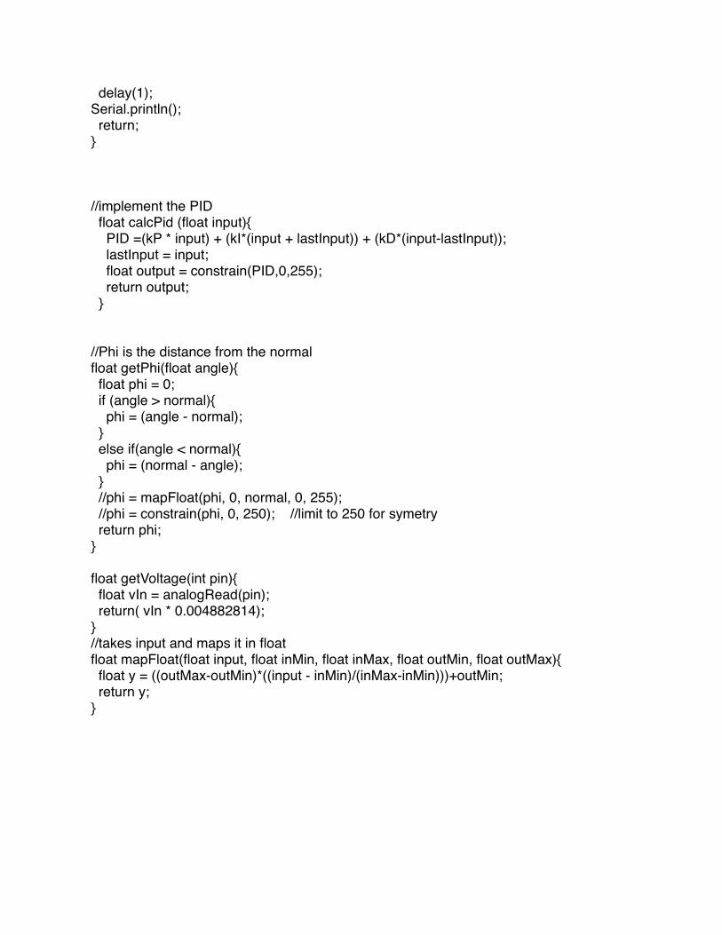
//implement the PID float calcPid (float input){ PID =(kP * input) + (kI*(input + lastInput)) + (kD*(input-lastInput)); lastInput = input; float output = constrain(PID,0,255); return output; }
//Phi is the distance from the normalfloat getPhi(float angle){ float phi = 0; if (angle > normal){ phi = (angle - normal); } else if(angle < normal){ phi = (normal - angle); } //phi = mapFloat(phi, 0, normal, 0, 255); //phi = constrain(phi, 0, 250); //limit to 250 for symetry return phi;}
float getVoltage(int pin){ float vIn = analogRead(pin); return( vIn * 0.004882814);}//takes input and maps it in floatfloat mapFloat(float input, float inMin, float inMax, float outMin, float outMax){ float y = ((outMax-outMin)*((input - inMin)/(inMax-inMin)))+outMin; return y;}
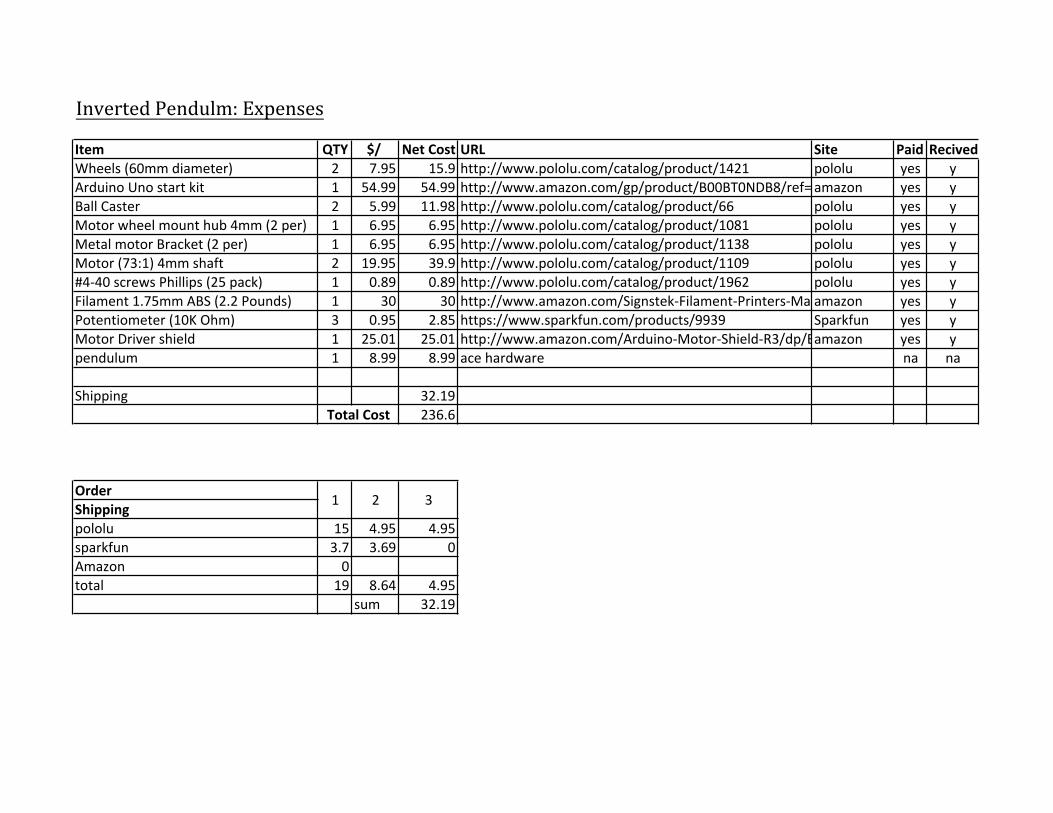
Inverted(Pendulm:(ExpensesItem QTY $/* Net*Cost URL Site Paid RecivedWheels&(60mm&diameter) 2 7.95 15.9 http://www.pololu.com/catalog/product/1421 pololu yes yArduino&Uno&start&kit 1 54.99 54.99 http://www.amazon.com/gp/product/B00BT0NDB8/ref=ox_sc_act_title_1?ie=UTF8&psc=1&smid=AHALS71WJO58Tamazon yes yBall&Caster& 2 5.99 11.98 http://www.pololu.com/catalog/product/66 pololu yes yMotor&wheel&mount&hub&4mm&(2&per) 1 6.95 6.95 http://www.pololu.com/catalog/product/1081 pololu yes yMetal&motor&Bracket&(2&per) 1 6.95 6.95 http://www.pololu.com/catalog/product/1138 pololu yes yMotor&(73:1)&4mm&shaft 2 19.95 39.9 http://www.pololu.com/catalog/product/1109 pololu yes y#4\40&screws&Phillips&(25&pack) 1 0.89 0.89 http://www.pololu.com/catalog/product/1962 pololu yes yFilament&1.75mm&ABS&(2.2&Pounds) 1 30 30 http://www.amazon.com/Signstek\Filament\Printers\MakerBot\Replicator/dp/B00E9444Q4/ref=sr_1_11?s=industrial&ie=UTF8&qid=1381866463&sr=1\11amazon yes yPotentiometer&(10K&Ohm) 3 0.95 2.85 https://www.sparkfun.com/products/9939 Sparkfun yes yMotor&Driver&shield 1 25.01 25.01 http://www.amazon.com/Arduino\Motor\Shield\R3/dp/B006UTE70E#productDetailsamazon yes ypendulum 1 8.99 8.99 ace&hardware na na
Shipping 32.19236.6
OrderShippingpololu 15 4.95 4.95sparkfun 3.7 3.69 0Amazon 0total 19 8.64 4.95
sum 32.19
Total*Cost
321


![Inverted Pendulum [Final]](https://img.dokumen.tips/doc/110x75/58904db31a28abcb668bcda8/inverted-pendulum-final.jpg)