Embed Size (px)
Citation preview
STA 1- SPACE TECHNOLOGIES
ON ALPINISM: PHASE ONE
Study and development of a high altitude mountaineering Mitt
Alexandre João Nunes Flórido
STA 1- SPACE TECHNOLOGIES
ON ALPINISM: PHASE ONE
Study and development of a high altitude mountaineering Mitt
Dissertation presented to the Department of Physics of the Faculty of Sciences
and Technology of the University of Coimbra, in fulfilment of the requirement to
obtain the degree of Master of Physics Engineering
Alexandre João Nunes Flórido
Coimbra, 4 September 2011

“Nas faldas do Himalaia, o Himalaia é só as faldas do Himalaia. É na distância ou na
memória ou na imaginação que o Himalaia é da sua altura, ou talvez um pouco mais
alto.”
Fernando Pessoa

I
ABSTRACT
Alpinism is a sport of high risk, with few practitioners. It is a demanding and dangerous
sport due to the extreme environmental conditions. The health consequences caused
by the very low temperatures and high-altitudes happen and are inevitable. However,
with appropriate equipment those sequels may take longer to settle in a severe way
and with permanent damages.
The present work, named STA 1 project, is the first phase of the bigger project “SPACE
TECHNOLOGIES ON ALPINISM”, and intends to develop a mitt, using the newest
technologies available and an intelligent system of temperature control, that will help
the alpinist perform without suffering severe consequences of long-term exposure to
the cold and high-altitude, like frostbite in the hands, causing amputation of the fingers,
and even compromise the athlete survival.
Keywords:
Alpinism, frostbite, hypoxia, dehydration, hypothermia, heat transfer, mitt, alpinist, High
Mountain, low temperature, high-altitude, thermal comfort, insulation materials, dew
point, relative humidity, metabolism.
II
RESUMO
O alpinismo de alta altitude é um desporto de alto risco, sendo poucos os praticantes
que o realizam. É um desporto exigente e perigoso devido às condições ambientais
extremas a que o alpinista se submete. As sequelas causadas pelo extremo frio e pelo
ar rarefeito acontecem e são inevitáveis, no entanto com um equipamento apropriado
podem demorar mais tempo a instalar-se de uma forma severa e com danos
permanentes.
O presente trabalho, designado por projecto STA 1, é a primeira fase do projecto maior
“SPACE TECHNOLOGIES ON ALPINISM”, e tem como objectivo o desenvolvimento
de uma luva, utilizando as tecnologias mais recentes, bem como um sistema
inteligente de controlo de temperatura, que ajuda o alpinista a realizar a sua expedição
sem que sofra sequelas graves causadas pela longa exposição ao do frio e à alta
altitude, como o enregelamento das mãos, que pode levar à amputação dos dedos ou
ao comprometimento da sobrevivência do atleta.
Palavras-chave:
Alpinismo, enregelamento, desidratação, hipotermia, transferência de calor, luva sem
dedos, alpinista, Alta Montanha, baixa temperaturas, alta altitude, conforto térmico,
materiais de isolamento, ponto de orvalho, humidade relativa, metabolismo.
III
ACKNOWLEDGEMENTS
The work developed provided me a great chance to increase my knowledge in this
area and to grow as a professional. For that, it is a pleasure to me to express my
gratitude to everyone who made this work possible.
I would like to thank Active Space Technologies for the opportunity that was given to
me and I would like to show especial gratitude to Eng. Abel Mendes for all the help and
guidance.
I must thank Dr. Francisco Fraga for all the help and availability to solve any problem
and to Prof. Dr. Rui Marques for all the discussion and help regarding the preparation
of this document.
I cannot end without thanking the professional Alpinist João Garcia for the inputs given
to this work, which became essential to all the decisions made for this Project.
To my family, that always supported me in all my decisions, I dedicate this work.
IV
TABLE OF CONTENTS
ABSTRACT ................................................................................................................... I
RESUMO ...................................................................................................................... II
ACKNOWLEDGEMENTS............................................................................................ III
TABLE OF CONTENTS .............................................................................................. IV
LIST OF FIGURES ..................................................................................................... VII
LIST OF GRAPHICS ................................................................................................. VIII
1. INTRODUCTION ...................................................................................................... 1
1.1. Motivation ........................................................................................................... 1
1.2. Project objectives ............................................................................................... 2
1.3. Dissertation Overview ......................................................................................... 2
1.4. Project Team ...................................................................................................... 3
2. THEORETICAL BACKGROUND ............................................................................. 4
2.1 The Human Body in High-Mountain ..................................................................... 4
2.1.1. Pathologies related to Alpinism .................................................................... 4
2.1.1.1. Dehydration ........................................................................................... 4
2.1.1.2. Hypothermia .......................................................................................... 6
2.1.1.3. Hypobaric Hypoxia ................................................................................ 8
2.1.1.4. Frostbite ................................................................................................ 9
2.1.2. Metabolism Process ................................................................................... 12
2.1.3. Arm Thermal Dynamic Behaviour .............................................................. 13
2.2. METEOROLOGICAL PARAMETERS .............................................................. 15
2.2.1. Relative Humidity ....................................................................................... 15
2.2.2. Dew Point .................................................................................................. 16
2.3. HEAT TRANSFER ........................................................................................... 17
2.3.1. Conduction ................................................................................................. 17
2.3.2. Convection ................................................................................................. 18
2.3.3. Thermal radiation ....................................................................................... 19
2.3.4. Thermal Resistance Concept ..................................................................... 20
2.4. Process control ................................................................................................. 22
2.4.1 Proportional controller ( ) ............................................................... 22
V
2.4.2 Integrative controller ( ) ................................................................... 23
2.4.3 Derivative controller ( )................................................................... 23
3. STA1 OVERVIEW .................................................................................................. 25
4. MATERIALS ........................................................................................................... 26
4.1. Multilayer Insulation Structure .......................................................................... 26
4.2. Vapour barriers ................................................................................................. 27
4.3. Proposed Solution ............................................................................................ 28
4.4. Types of Materials ............................................................................................ 29
4.4.1. Water Proof Fabrics (Layer 1 and 3) .......................................................... 29
4.4.2. Insulation materials (Layer 2) ..................................................................... 31
4.4.3. Spacer Fabrics (Layer 4) ............................................................................ 33
4.2.1. Lining Fabrics (Layer 5) ............................................................................. 33
4.5. Heat Transfer Calculations ............................................................................... 36
4.5.1. Calculus of the heat flux ............................................................................. 36
4.5.2. Calculus of the insulation thickness of the mitt (general) ............................ 41
4.5.3. Calculus of the insulation thickness of the mitt (palm area) ........................ 45
5. ELECTRONIC SYSTEM DEVELOPMENT ............................................................. 47
5.1. Human Machine Interface (HMI) ....................................................................... 48
5.1.1. Display ....................................................................................................... 49
5.1.2. Keyboard ................................................................................................... 50
5.1.3. Visual Arrangement and Functionality ........................................................ 51
5.1.4. HMI Software Implementation .................................................................... 53
5.2. Temperature Sensor......................................................................................... 55
5.3. Heat Resistors .................................................................................................. 55
5.3.1. Temperature control ................................................................................... 56
5.4. Power Management Module ............................................................................. 57
5.4.1. Battery ....................................................................................................... 58
5.4.2. Battery Management .................................................................................. 58
5.4.3. Solar panel ................................................................................................. 60
5.4.4. DC/DC Converters ..................................................................................... 60
5.5. Communication module .................................................................................... 60
5.5.1. Wireless Module ........................................................................................ 60
5.5.1.1. MiWi™ ................................................................................................. 61
VI
5.6. Microcontroller .................................................................................................. 65
6. DESIGN CONSIDERATIONS ................................................................................. 68
7. TESTS AND VALIDATION ..................................................................................... 72
8. CONCLUSION ........................................................................................................ 73
9. FUTURE WORK ..................................................................................................... 74
ACRONYMS ............................................................................................................... 75
GLOSSARY ............................................................................................................... 77
REFERENCES ........................................................................................................... 84
ANNEX A – Efficiency and Metabolic Rate for typical tasks
VII
LIST OF FIGURES
FIG 1 – RED, BLUE AND WHITE FINGERS ASSOCIATED WITH RAYNAUD'S PHENOMENON ...................... 11
FIG 2 - FROSTBITTEN HAND ........................................................................................................... 12
FIG 3 – FROSTBITE DEGREES INJURIES: (A) FIRST DEGREE; (B) SECOND DEGREE; (C) THIRD AND
FOURTH DEGREE .................................................................................................................... 12
FIG 4 - BLOOD CIRCULATION OF THE ARM ....................................................................................... 14
FIG 5 - ARM THERMAL DYNAMIC SCHEME ........................................................................................ 15
FIG 6 - HEAT CONDUCTION THROUGH A LARGE PLAN WALL OF THICKNESS AND AREA ........ 18
FIG 7 - THE ABSORPTION OF RADIATION INCIDENT ON AN OPAQUE SURFACE OF ABSORPTIVITY (18)
...... 20
FIG 8 – PROCESS CONTROL DIAGRAM ............................................................................................ 22
FIG 9 – PID DIAGRAM .................................................................................................................... 24
FIG 10 – INTERFACE BETWEEN TWO MATERIALS (18)
......................................................................... 27
FIG 11 – MITT MATERIAL STRUCTURE ............................................................................................. 28
FIG 12 – RIP STOP FABRIC4 .......................................................................................................... 30
FIG 13 – A) SELECTED RIP STOP FABRIC; B) HEAT TRANSFER TROUGH BLACK AND SILVER MATERIAL 30
FIG 14 – SPACER FABRIC (20)
.......................................................................................................... 33
FIG 15 – TEMPERATURE IN THE INNER STRUCTURE OF THE MITT ...................................................... 35
FIG 16 - EQUIVALENT HEAT RESISTANCE AT THE SURFACE OF THE CLOTHING ................................... 39
FIG 17 - MITT INSULATION STRUCTURE SCHEME (GENERAL) ............................................................ 42
FIG 18 - MITT INSULATION STRUCTURE SCHEME (PALM AREA) .......................................................... 45
FIG 19 - RIGHT MITT ELECTRONIC DEVICE ....................................................................................... 48
FIG 20 - HUMAN MACHINE INTERFACE ............................................................................................ 49
FIG 21 - DISPLAY COLOUR NOKIA LCD .......................................................................................... 49
FIG 22 - FIBRETRONICS™ CONNECTED WEAR LINEAR KEYPAD ....................................................... 50
FIG 23 - KEYBOARD SCHEME ......................................................................................................... 50
FIG 24 - HMI MENU 1 .................................................................................................................... 51
FIG 25 - CHARGING STATE INDICATORS .......................................................................................... 52
FIG 26 - KEYBOARD BUTTONS ........................................................................................................ 52
FIG 27 - HMI MENU 2 .................................................................................................................... 53
FIG 28 - LCD RGB PACKAGE ........................................................................................................ 53
FIG 29 - HMI WORKFLOW DIAGRAM ................................................................................................ 54
FIG 30 - SENSING MODULE ............................................................................................................ 55
FIG 31 - FLEXIBLE HEATER ............................................................................................................ 56
FIG 32 - TEMPERATURE CONTROL MODULE .................................................................................... 56
FIG 33 - TEMPERATURE CONTROL WORKFLOW DIAGRAM ................................................................. 57
FIG 34 - BATTERY MANAGEMENT MODULE ...................................................................................... 58
FIG 35 - BQ24113A TYPICAL CHARGING PROFILE (25)
...................................................................... 59
FIG 36 - COMMUNICATION MODULE ................................................................................................ 60
FIG 37 - MICROCHIP MRF24J40MA ZIGBEE MODULE (27)
................................................................ 61
FIG 38 - MIWI™
DEVELOPMENT ENVIRONMENT INTERFACE LAYERS (26)
............................................ 62
VIII
FIG 39 - MIWI™
DEVELOPMENT ENVIRONMENT HARDWARE SCHEME (27)
........................................... 63
FIG 40 - TYPICAL HANDSHAKING IN IEEE 802.15.4™ (28)
................................................................. 63
FIG 41 - HANDSHAKING PROCESS FOR MIWI™
P2P WIRELESS PROTOCOL (28)
................................... 64
FIG 42 - STA 1 COMMUNICATION ALGORITHM ................................................................................. 65
FIG 43 - MICROCONTROLLER CONNECTION TYPES .......................................................................... 66
FIG 44 – LEFT MITT ELECTRONIC SYSTEM ....................................................................................... 67
FIG 45 – RIGHT MITT ELECTRONIC SYSTEM ..................................................................................... 67
FIG 46 - MITT LAYERS DESIGN STRUCTURE ................................................................................... 68
FIG 47 - (A) HMI PLACEMENT; (B) WRIST NYLON STRAP FOR ADJUSTMENT ........................................ 69
FIG 48 - (A) NYLON STRAP (MITT OPENING); (B) NYLON STRAP FUNCTION ......................................... 70
FIG 49 - BATTERY PLACEMENT ....................................................................................................... 70
FIG 50 - MITT BACK WITH SQUARE OF SOFT FABRIC ......................................................................... 71
LIST OF TABLES
TABLE 1 - PROJECT TEAM .............................................................................................................. 3
TABLE 2 - WATERPROOF MATERIALS AVAILABLE ............................................................................ 29
TABLE 3 –INSULATION MATERIALS AVAILABLE ................................................................................ 31
TABLE 4 – LINING FABRICS AVAILABLE ........................................................................................... 34
LIST OF GRAPHICS
GRAPHIC 1 – ATMOSPHERIC PRESSURE VERSUS ALTITUDE ............................................................. 8
GRAPHIC 2 – DEW POINT VERSUS AMBIENT TEMPERATURE ........................................................... 35
STA 1
1
1. INTRODUCTION
1.1. MOTIVATION
Alpinism is a very demanding activity because it is practiced on extreme environmental
conditions, and is not unusual to hear about people dying during expeditions. In fact, as
an example, between the year 2000 and 2010, the K2 Mountain has taken the life of
over 20% of its climbers (1). The cold and the altitude are the main enemies of the
alpinist. To overcome these two obstacles, certain conditions are necessary to ensure
the survival of the climber. These conditions are related with nutrition, hydration,
clothing, equipment, experience, etc. When everything goes as expected, the climber
ascends, accomplishes his goal and then descends without major sequels, but it is not
always like that. After reaching the top successfully, many people suffer the
consequences of their audacity, during descend.
The most common sequels that people suffer are the lost of weight, dehydration and
the lost of the body extremities (ears, nose, fingers and toes). The consequences due
to coldness are often a sign of not wearing adequate clothing. A garment that does not
allow the use of the heat produced by the human body will make the body activate
physiological mechanisms to protect itself from extreme environmental conditions, but
due to the extreme conditions, the body cannot maintain the balance. In order to cope
with its limitation, the body starts to take survival measures, like blocking the blood
supply to the extremities.
In the last 20 years, there was not significant development in sports clothing, related to
Alpinism (1). With today’s technology, it shall be possible to optimize the clothing in
alpinism in a way that maximizes the comfort of the athlete, significantly reducing some
of the consequences caused by the cold.
STA 1
2
1.2. PROJECT OBJECTIVES
The objectives for the STA 1 are:
1. Design a mitt that prevents the alpinist hands temperature of reaching
dangerous values, which results in permanent damages;
2. Guarantee the maintenance of a proper hand temperature with the help of an
electronic control heating system, during an expedition in high-mountain above
7000m with temperatures of -30ºC and a wind of 10m/s;
3. Develop an adequate solution to Alpinism needs, making more efficient than the
solutions available in today’s market;
1.3. DISSERTATION OVERVIEW
The present document is divided into 7 chapters. This section makes a brief description
of each one.
INTRODUCTION – a brief introduction to the project is presented, as well as the
motivation, the project objectives and an overview of the team involved in this project.
THEORECTICAL BACKGROUND – provides the information related to the
physiological behaviour of the human body at low temperatures and explains some of
its consequences. Includes basic concepts about some meteorological parameters,
and theoretical concepts regarding heat transfer.
SYSTEM OVERVIEW – in this chapter, it is included a global presentation of the
solution found to accomplish the project objectives.
MATERIALS – presents the materials applied in today’s sports (hi-tech fabrics) their
characteristics as well as a technical discussion that leads to a proposed solution to
solve the problem in question and finally the materials chosen for the project. It also
presents the calculation of heat transfer.
STA 1
3
ELECTRONIC SYSTEM DEVELOPMENT – in this chapter are explained all the
choices made to accomplish every part of the electronic thermal control of the mitt.
THERMAL TEST VALIDATION – here are analyzed the results of the tests that were
performed with the mitt prototype.
CONCLUSIONS – the final impressions, concerning the mitt prototype, are presented.
FUTURE WORK – it contains, after the obtained results, the issues that could need
improvement and features for future prototypes.
1.4. PROJECT TEAM
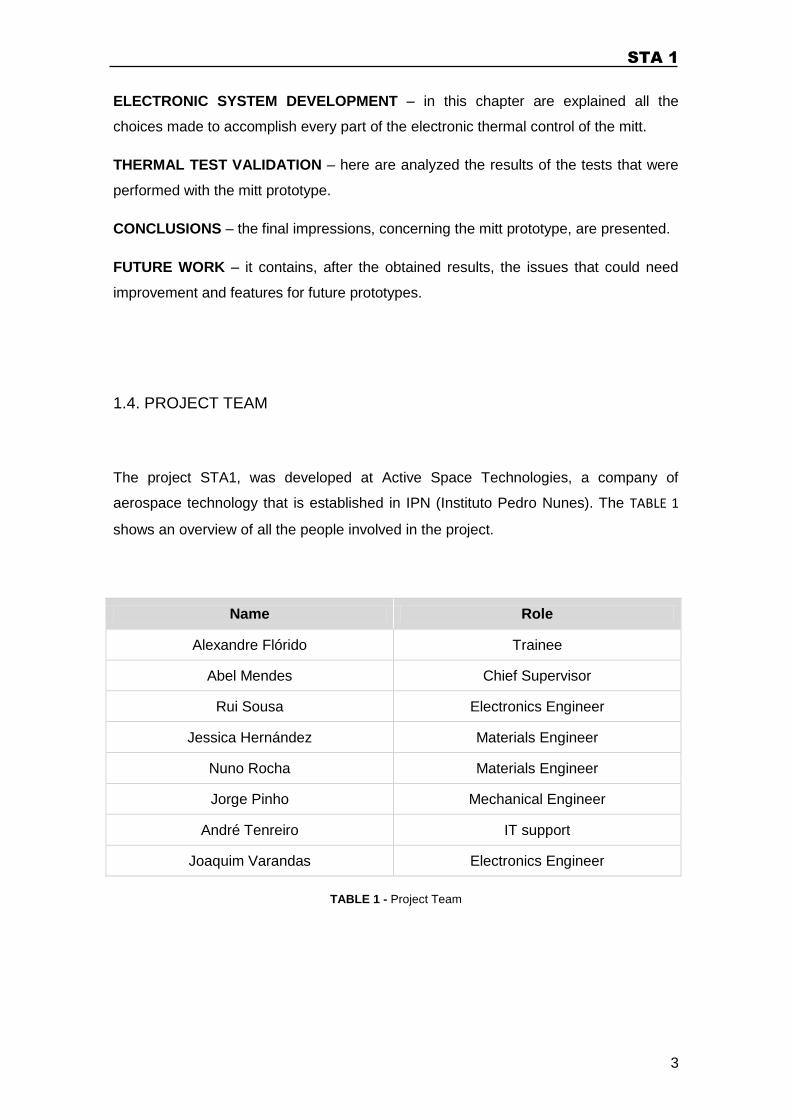
The project STA1, was developed at Active Space Technologies, a company of
aerospace technology that is established in IPN (Instituto Pedro Nunes). The TABLE 1
shows an overview of all the people involved in the project.
Name Role
Alexandre Flórido Trainee
Abel Mendes Chief Supervisor
Rui Sousa Electronics Engineer
Jessica Hernández Materials Engineer
Nuno Rocha Materials Engineer
Jorge Pinho Mechanical Engineer
André Tenreiro IT support
Joaquim Varandas Electronics Engineer
TABLE 1 - Project Team
STA 1
4
2. THEORETICAL BACKGROUND
2.1 THE HUMAN BODY IN HIGH-MOUNTAIN
Over the past few years there was an increased interest of people towards mountain
sports. Some of these, including mountaineering and skiing, are practices in a non
natural environment for human beings. Man is the only living being native to the
regions at sea level that exposes himself, deliberately and for reasons other than those
of survival, to the rigors of very low temperatures and hypoxic environments present in
mountains of high altitude. This kind of behaviour puts the body to the test and triggers
physiological reactions that guarantee its survival. But sometimes those reactions are
extreme causing organic unbalances (dehydration, hypothermia and hypoxia) and
mutilations (frostbite). For these reasons, great emphasis has been given to the study
of human physiological response to high altitude environments (1; 2).
In this chapter it will be discussed some consequences of the very low temperatures
and high altitudes in the human body, as well as a brief explanation of the metabolism
process. The understanding of these subjects was important because it helped to
decide the best strategy to fulfil the project goals.
2.1.1. Pathologies related to Alpinism
2.1.1.1. Dehydration
Dehydration is one of the main health hazards associated with cold environments.
Studies made in the U.S.A. showed an increased risk for dehydration in cold
environments, a condition more commonly associated with hot weather (3).
Dehydration is defined as the excessive loss of body fluid. When it occurs, there is an
unbalance between the amount of water eliminated and the amount of water ingested
(4; 5).
Water is vital for our body’s normal function. In normal conditions, our body maintains a
constant total volume of water, being "the total amount of water in an average weight
STA 1
5
man ( ) approximately , representing of his total body weight.” Normally
the amount ingested is the same as the eliminated. The total volume of water that
enters in the body varies between , a day. Most of it ( ) comes from
the liquids we ingest and comes from the food and from the cellular metabolism
(5).
The excessive loss of body water is a dangerous situation. In normal condition our
body looses water in three different ways. The major amount is trough urine, The
evaporation via the airways and by the skin (sweat) represents, approximately, of
the lost water. The remaining 4% represent the lost of water by faeces (5).
The amount of water lost by sweat and by the respiratory system depends on the
environmental temperature, pressure, humidity, body temperature and the volume of
air exhaled. All this regulation is maintained by the hypothalamus. The anterior
hypothalamus detects small temperature increases; the posterior hypothalamus
detects small temperature decreases. When the body core temperature rises, the body
releases water in the form of vapour (sweat), quickly decreasing the temperature.
When the body core temperature decreases, the body reacts constricting the vessels
and shivering. The mechanism seems very simple and logic, but at low temperatures
and high-altitude the human body is in an extreme situation and struggles to keep the
balance. At those extreme conditions the environment changes so quickly that the
human body doesn’t have the capacity to compensate at the same pace and for that
fact the heat and fluid losses are higher than they should be (4; 5).
As we mentioned earlier, the higher loss of water is through urine ( ). That
percentage was determined in “normal” environmental conditions ( and ), but
at low temperatures the loss of water by urine is even higher, because the body needs
to increase the body core temperature, and when it contracts the vessels
(vasoconstriction) of the body extremities, the blood circulatory volume decreases and
the arterial blood pressure increases, so the body releases the arterial blood pressure
producing more urine. That mechanism combined with the low atmospheric pressure in
high-altitude (osmosis mechanism) provides an inevitable dehydration of the body (1; 5).
In a primary stage of dehydration, the body activates the sensation of thirst to increase
water intake and decreases the urine output to try to conserve water loss. The urine
becomes more concentrated and more yellow in colour. As the water loss increases,
more symptoms appear. Below are presented symptoms of a more severe dehydration
(3):
STA 1
6
Dry mouth;
The eyes stop producing tears;
Sweating may stop;
Muscle cramps;
Nausea and vomiting;
Heart palpitations (Tachycardia);
Light-headedness (especially when standing);
Weakness;
Decreased urine output
The body tries to maintain the cardiac output (amount of blood pumped by the heart to
the body). If the amount of fluid in the intravascular space is decreased, the body tries
to compensate that deficit, raising the heart rate (tachycardia) and constricting the
vessels, in order to maintain the blood pressure and the right oxygenation of the vital
organs. This mechanism begins to fail as the level of dehydration becomes more
severe. When there is a high level of dehydration, mental confusion and body
weakness appear, because the brain and the other vital organs don’t have enough
blood supply. A stroke may happen too, because the blood is too thick and may form
clots. If not treated, dehydration becomes a life threat situation, leading to a coma or, in
the worst case scenario, to death (trough organ failure) (3).
2.1.1.2. Hypothermia
Hypothermia is one of the problems that the human body faces when dealing with cold
environments. It’s important to know what it is, how it happens, what the symptoms are
and how to prevent it.
The human body maintains a relatively stable temperature; the heat production is
balanced by heat loss. Hypothermia occurs when the normal core temperature of the
body, ( ), decreases for less than ( ). When a person is exposed
to a cold environment (wind, snow, rain or water immersion) the body’s heat production
decreases and hypothermia occurs (hypo=less + thermia=temperature). Anyone
exposed to cold temperatures, whether for work or recreation, may be at risk of
becoming too cold (1; 4).
STA 1
7
Hypothermia is a physiological reaction, consequence of a long-term exposure to cold
environments. Normal body temperature it’s a delicate balance between heat
production and heat loss. Its right balance is essential because there are specific
chemical reactions, which allow the survival of the human body, that only occur in
specific temperatures ranges. The brain, more specifically the hypothalamus, is the
organ that coordinates all the mechanisms that maintain vital temperature, and if these
mechanisms are overwhelmed, heat loss happens faster than heat production,
resulting in hypothermia (2; 4).
The signs and symptoms change depending on the degree of hypothermia and can be
described in four stages of severity (mild, moderate, severe and profound) (6). The
distinctions among mild, moderate, severe and profound hypothermia are not often
clear, but the constant sequence of events occur as the body core temperatures
continues to decline.
Mild hypothermia: 35ºC to 32ºC (95ºF to 89.6ºF). The symptoms are
mechanisms to preserve and produce heat: shivering, hypertension,
tachycardia, tachypnea and vasoconstriction. In this stage, some people may
present already some confusion, apathy, lethargy, cold diuresis and
hypoglycaemia (2; 6).
Moderate hypothermia: 32ºC to 28ºC (89.6ºF to 82.4ºF). At this degree of
severity the shivering becomes more violent and eventually stops, because it
spends too much energy. The heart rate decreases (bradycardia) and becomes
irregular (arrhythmia). Muscle discoordination becomes evident and the
movements are very slow and laboured. The mental confusion, or delirium,
appears due to the vasoconstriction in the brain, but the individual may seem
alert. In this degree of hypothermia the body also initiates the vasoconstriction
of the extremities, because the body focuses its remaining resources on
keeping the vital organs warm. The victim becomes pale and the lips, ears,
fingers and toes may become blue (cyanosis). There is a high risk of frostbite (2;
6).
Severe hypothermia: below 28ºC (82.4ºF) the cellular metabolic process shut
down, “…walking becomes almost impossible, and the victim exhibits
incoherent/irrational behaviour, including terminal burrowing behaviour or even
a stupor (…) Pulse and respiration rates decrease significantly, but fast heart
rates (ventricular tachycardia and ventricular fibrillation) can occur.” (2; 6)
STA 1
8
Profound hypothermia: below 20ºC (68ºF). Major organs fail happens, brain
activity stops and clinical death occurs (2; 6).
Hypothermia is a serious and deathly consequence of the extreme cold and must be
prevented. A good nutrition sate and appropriate clothes are vital (2).
2.1.1.3. Hypobaric Hypoxia
Hypoxia is a state of low presence of oxygen in the body tissues, whose occurrence is
attributed to several factors. It may be caused by internal factors like an anomaly in the
mechanism of transport of oxygen, a physical obstruction of the blood flow in the
vascular system and anaemia or by external factors like low concentration of oxygen in
the air environment (high-altitudes). Hypobaric is related to “conditions of low air
pressure and low oxygen content, such as atmospheric conditions at high-altitudes, or
in special chambers used to establish low-pressure conditions.” (7; 8)
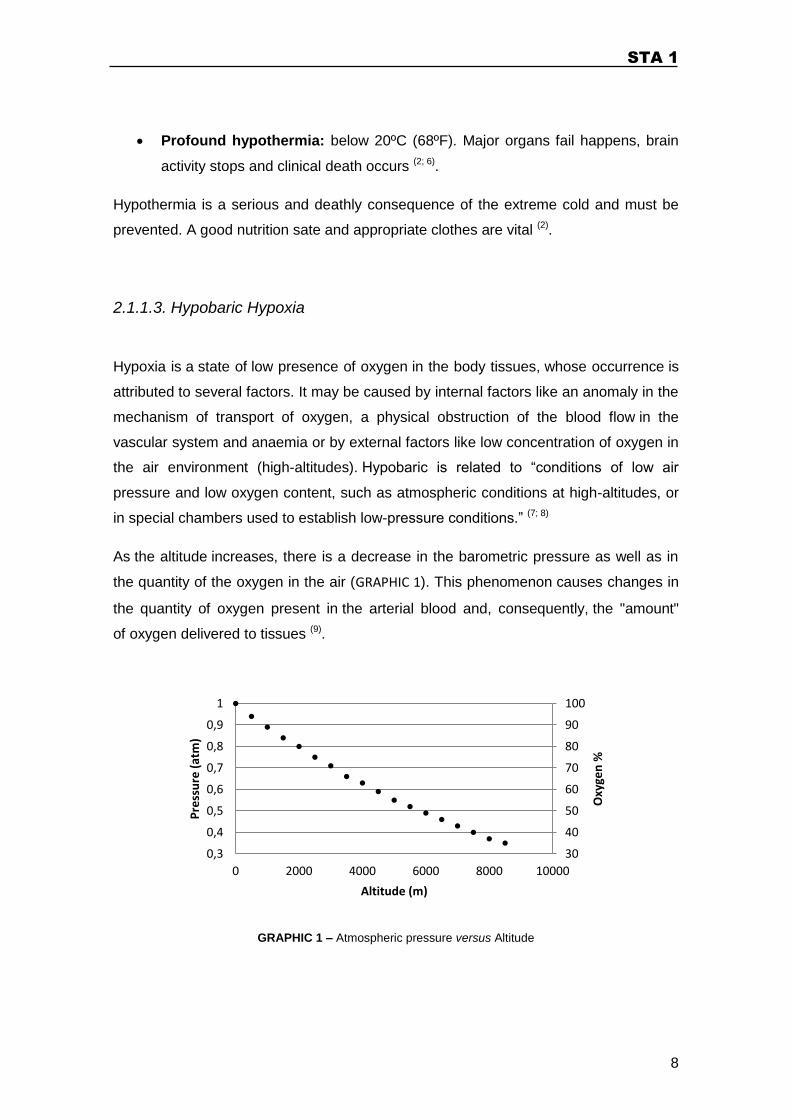
As the altitude increases, there is a decrease in the barometric pressure as well as in
the quantity of the oxygen in the air (GRAPHIC 1). This phenomenon causes changes in
the quantity of oxygen present in the arterial blood and, consequently, the "amount"
of oxygen delivered to tissues (9).
GRAPHIC 1 – Atmospheric pressure versus Altitude
30
40
50
60
70
80
90
100
0,3
0,4
0,5
0,6
0,7
0,8
0,9
1
0 2000 4000 6000 8000 10000
Oxy
gen
%
Pre
ssu
re (
atm
)
Altitude (m)
STA 1
9
Evangelista Torricelli, disciple of Galileo, was the first person to assume that
air had weight. As he stated in 1644, „we live submerged in the bottom of an ocean of
air that, through unquestionable experiments, have weight on us.‟ So, taking as
reference the barometric pressure at sea level (760 mmHg), as we climbed in altitude
the pressure exerted by this layer of air (barometric pressure) decreases. At an altitude
of 5800 meters, the barometric pressure decreases to about half (379 mmHg) of the
value reported at sea level and on the summit of Everest (8850 m) assumes values of
about one-third (253 mmHg) of the sea level pressure. The quantity of breathable
oxygen is directly proportional to the barometric pressure; the higher we climb the less
oxygen is available (GRAPHIC 1) (1; 9).
The diffusion of oxygen, which occurs in the pulmonary alveolus, to the tissues, is
conditioned by the pressure gradient in the different levels at which gas exchange
occurs. So, the decrease of PIO2 (partial pressure of inspired oxygen) adversely affects
the rate of diffusion of oxygen from the pulmonary alveolus to pulmonary capillaries.
That way there is a reduction in the percentage of the haemoglobin saturation and,
consequently, less oxygen is transported to the tissues. As we ascend in altitude, the
decrease of oxygen available for cellular metabolism complicates the permanence and
performance of humans and has repercussions in various forms in the homeostasis of
different biological systems (9).
The exposure to environments of hypobaric hypoxia induces numerous physiological
adaptations, which tend to minimize the negative effect of reduced amount of oxygen
available for the different tissues. Those adaptations occur in the respiratory system
(dyspnea), circulatory system (hypertension, tachycardia), hormonal regulation
(increase of erythropoietin) and hematologic components, among others (9).
The hypoxia symptoms depend on its severity. The primary symptoms include mental
confusion, headache, fatigue, dyspnea, hypertension, tachycardia, a feeling of
euphoria, hot and cold flashes and visual impairment. In severe hypoxia the victim
changes in levels of consciousness, present cyanosis in all extremities (ears, lips,
nose, fingers and toes), may present seizures and death may occur (6).
2.1.1.4. Frostbite
Frostbite is a condition resulting from excessive and continuous exposure of the skin to
very low temperatures, causing the freezing of the tissues. When there is frostbite,
STA 1
10
there is already hypothermia. Frostbite and hypothermia are both cold-related
emergencies (10).
This condition has long been recognized. The oldest and most famous known case of
frostbite and hypothermia is Ötzi, the pre-historic men discovered in the Chilean
mountains, freeze during 5000 years. More recently, Napoleon's surgeon general,
Baron Dominique Larrey, described for the first time the mechanism of frostbite, in
1812 during Napoleon’s army retreat from Moscow. He also mentions the harmful
effects of the freeze-thaw-freeze cycle suffered by the soldiers who would warm their
frozen hands and feet over the campfire at night only to refreeze those same parts by
the next morning. Frostbite was formerly a military problem, but today is also a civilian
one as well, because the alpinism, as a sport, has been gaining more and more
practitioners (1; 10).
Everyone is susceptible to frostbite, even those who live in cold climates most of their
lives. The extremities of the human body (nose, ears, fingers and toes) are the most
commonly affected (11).
Physiologically, the frostbite phenomenon happens when the exterior temperature
decreases, the vessels contract and the skin becomes pallid But when the skin is
exposed to a temperature below 10ºC the superficial vessels of the skin dilate in order
to warm up the extremity. It is possible to visualize this mechanism in action, when we
see the redness of the nose, ears and hands, characteristic of cold weather. If the
temperature continues to drop, the vessels begin to constrict and dilate intermittently,
causing pain and throbbing. This pain is due to the toxic metabolites that are released
in the contraction phase, when the tissues have no blood supply. However, these
oscillations prevent that the intense cold damages the tissues and provides enough
blood supply, although intermittent. If the temperature continuous to drop excessively
the superficial blood vessels contracts continuously and the tissues temperature is
balanced with the exterior temperature, causing frostbite (1; 9; 10).
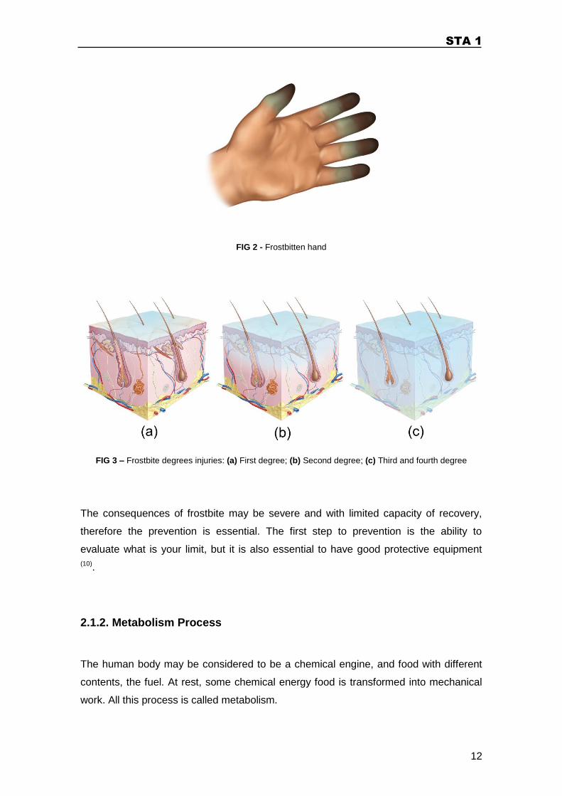
Frostbite (FIG 2 and FIG 3) has four degrees (11):
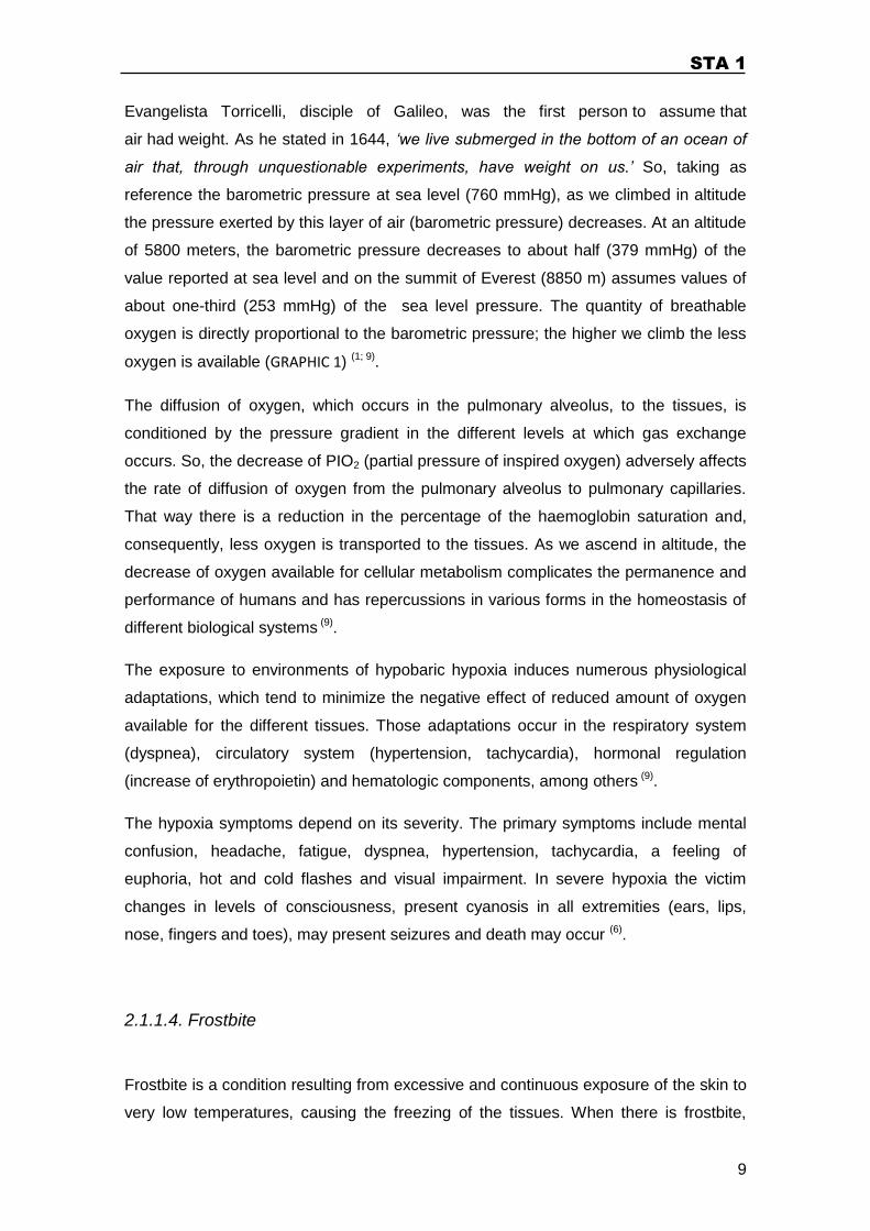
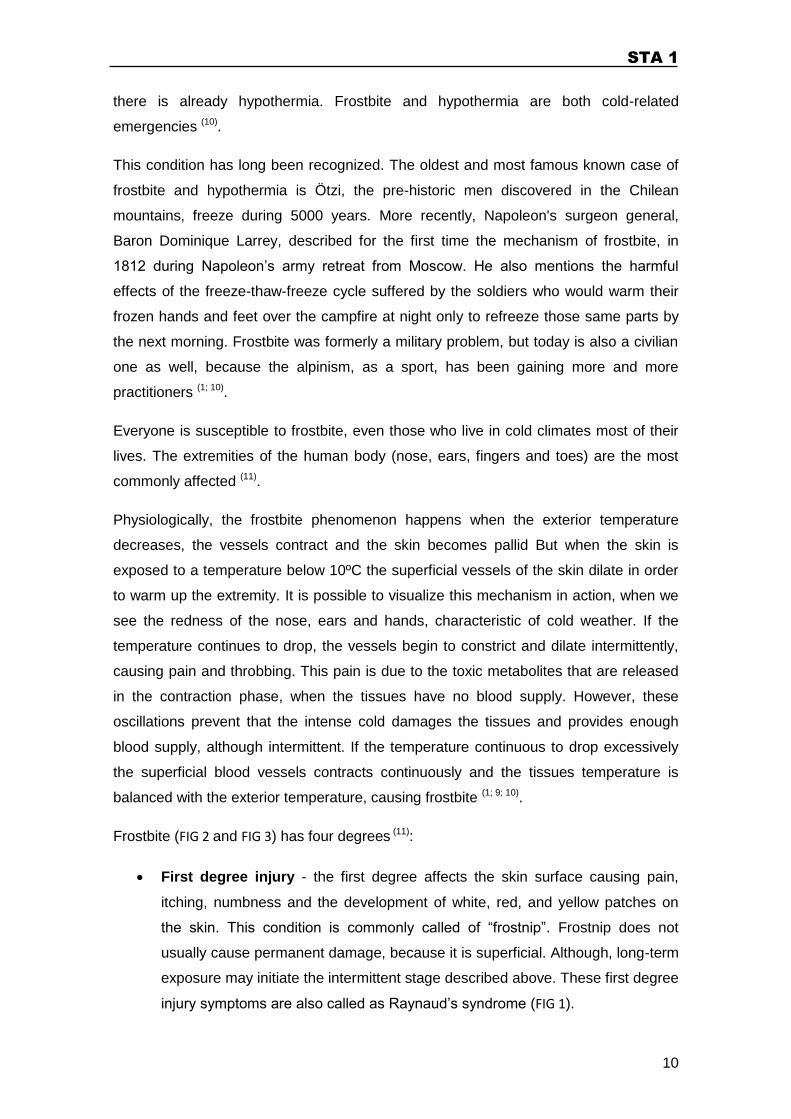
First degree injury - the first degree affects the skin surface causing pain,
itching, numbness and the development of white, red, and yellow patches on
the skin. This condition is commonly called of “frostnip”. Frostnip does not
usually cause permanent damage, because it is superficial. Although, long-term
exposure may initiate the intermittent stage described above. These first degree
injury symptoms are also called as Raynaud’s syndrome (FIG 1).
STA 1
11
FIG 1 – Red, blue and white fingers associated with Raynaud's phenomenon
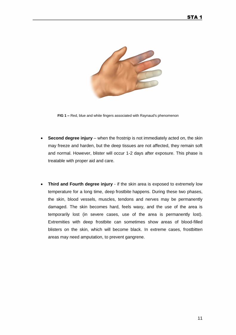
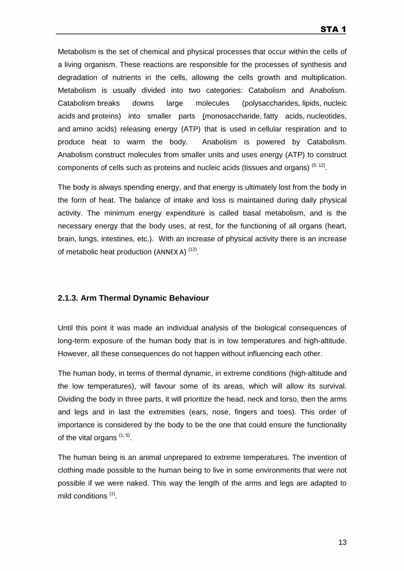
Second degree injury – when the frostnip is not immediately acted on, the skin
may freeze and harden, but the deep tissues are not affected, they remain soft
and normal. However, blister will occur 1-2 days after exposure. This phase is
treatable with proper aid and care.
Third and Fourth degree injury - if the skin area is exposed to extremely low
temperature for a long time, deep frostbite happens. During these two phases,
the skin, blood vessels, muscles, tendons and nerves may be permanently
damaged. The skin becomes hard, feels waxy, and the use of the area is
temporarily lost (in severe cases, use of the area is permanently lost).
Extremities with deep frostbite can sometimes show areas of blood-filled
blisters on the skin, which will become black. In extreme cases, frostbitten
areas may need amputation, to prevent gangrene.
STA 1
12
FIG 2 - Frostbitten hand
FIG 3 – Frostbite degrees injuries: (a) First degree; (b) Second degree; (c) Third and fourth degree
The consequences of frostbite may be severe and with limited capacity of recovery,
therefore the prevention is essential. The first step to prevention is the ability to
evaluate what is your limit, but it is also essential to have good protective equipment
(10).
2.1.2. Metabolism Process
The human body may be considered to be a chemical engine, and food with different
contents, the fuel. At rest, some chemical energy food is transformed into mechanical
work. All this process is called metabolism.
STA 1
13
Metabolism is the set of chemical and physical processes that occur within the cells of
a living organism. These reactions are responsible for the processes of synthesis and
degradation of nutrients in the cells, allowing the cells growth and multiplication.
Metabolism is usually divided into two categories: Catabolism and Anabolism.
Catabolism breaks downs large molecules (polysaccharides, lipids, nucleic
acids and proteins) into smaller parts (monosaccharide, fatty acids, nucleotides,
and amino acids) releasing energy (ATP) that is used in cellular respiration and to
produce heat to warm the body. Anabolism is powered by Catabolism.
Anabolism construct molecules from smaller units and uses energy (ATP) to construct
components of cells such as proteins and nucleic acids (tissues and organs) (5; 12).
The body is always spending energy, and that energy is ultimately lost from the body in
the form of heat. The balance of intake and loss is maintained during daily physical
activity. The minimum energy expenditure is called basal metabolism, and is the
necessary energy that the body uses, at rest, for the functioning of all organs (heart,
brain, lungs, intestines, etc.). With an increase of physical activity there is an increase
of metabolic heat production (ANNEX A) (12).
2.1.3. Arm Thermal Dynamic Behaviour
Until this point it was made an individual analysis of the biological consequences of
long-term exposure of the human body that is in low temperatures and high-altitude.
However, all these consequences do not happen without influencing each other.
The human body, in terms of thermal dynamic, in extreme conditions (high-altitude and
the low temperatures), will favour some of its areas, which will allow its survival.
Dividing the body in three parts, it will prioritize the head, neck and torso, then the arms
and legs and in last the extremities (ears, nose, fingers and toes). This order of
importance is considered by the body to be the one that could ensure the functionality
of the vital organs (1; 5).
The human being is an animal unprepared to extreme temperatures. The invention of
clothing made possible to the human being to live in some environments that were not
possible if we were naked. This way the length of the arms and legs are adapted to
mild conditions (1).
STA 1
14
For the purpose of this work, it will be considered a more detail analysis of the arm.
Anatomically the arms provide us a tool that allows the manipulation of the objects. In
cold environments the arms acts as a cooler, due to its length and form (13).
In high altitude the atmospheric pressure and temperature are low, making the relative
humidity also low. The lower the atmospheric relative humidity, the greater
the separation between the values of partial vapour pressure and saturation vapour
pressure making the sweat pass more easily into a gaseous state. This phenomenon
contributes to the dehydration of the body. During physical activity the body releases
heat in the form of hot vapour to cool off. If that vapour condenses in the skin, the heat
is transferred again to the body, giving the sensation of warm. However, at very low
temperatures the hot vapour leaves the body and touch the clothing fabric, which has a
lower temperature than the body, condensing. The condensed vapour will increase the
thermal conduction of the fabric insulation, leading to a reduction of the inner
temperature of the clothing. In conclusion, the thermal efficiency of the clothing is
compromised (14; 15).
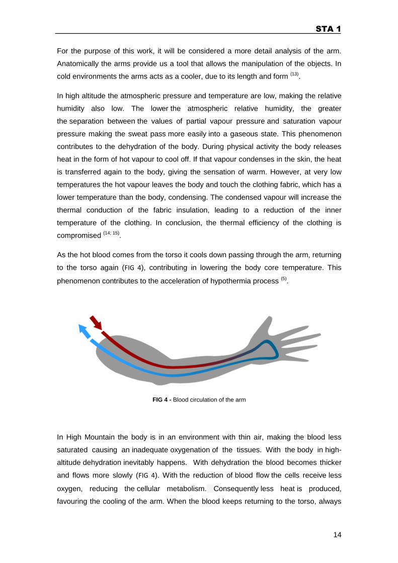
As the hot blood comes from the torso it cools down passing through the arm, returning
to the torso again (FIG 4), contributing in lowering the body core temperature. This
phenomenon contributes to the acceleration of hypothermia process (5).
FIG 4 - Blood circulation of the arm
In High Mountain the body is in an environment with thin air, making the blood less
saturated causing an inadequate oxygenation of the tissues. With the body in high-
altitude dehydration inevitably happens. With dehydration the blood becomes thicker
and flows more slowly (FIG 4). With the reduction of blood flow the cells receive less
oxygen, reducing the cellular metabolism. Consequently less heat is produced,
favouring the cooling of the arm. When the blood keeps returning to the torso, always
STA 1
15
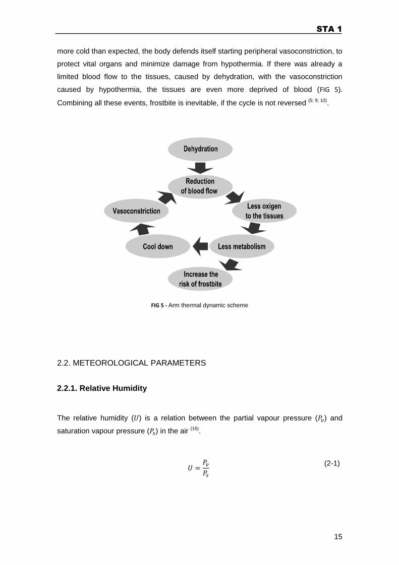
more cold than expected, the body defends itself starting peripheral vasoconstriction, to
protect vital organs and minimize damage from hypothermia. If there was already a
limited blood flow to the tissues, caused by dehydration, with the vasoconstriction
caused by hypothermia, the tissues are even more deprived of blood (FIG 5).
Combining all these events, frostbite is inevitable, if the cycle is not reversed (5; 9; 10).
FIG 5 - Arm thermal dynamic scheme
2.2. METEOROLOGICAL PARAMETERS
2.2.1. Relative Humidity
The relative humidity ( ) is a relation between the partial vapour pressure ( ) and
saturation vapour pressure ( ) in the air (16).
(2-1)
STA 1
16
In perceptual form,
(2-2)
2.2.2. Dew Point
When a portion of air that contains a constant amount of moister is gradually cooled
down the air humidity will saturate, forcing the water to condensate. The temperature at
which the moister will condensate is called Dew point. The dew point equation is
deduced using the Magnus-Tetens formula ( ) (17).
(2-3)
The dew point ( ) can be also determined by the equation (18),
(2-4)
Where,
(2-5)
The parameter and represent the Magnus formula constants. Where and
.
STA 1
17
2.3. HEAT TRANSFER
Energy can be transfer as heat from one system to another, as the result of
temperature difference. The heat transfer is always made from de higher temperature
body to the lower one. This mechanism stops when the same temperature is reached.
Heat can be transferred in three different ways: Conduction, Convection and Radiation
(18).
2.3.1. Conduction
When particles with different energy interact, the more energetic one will transfer
energy to the less energetic one. This process is called Conduction (18).
The rate of heat conduction, through a surface, is conditioned by the shape, thickness
and the temperature gradients in the material. The rate of heat transfer ( ), through a
plane wall, could be define by the equation (18).
(2-6)
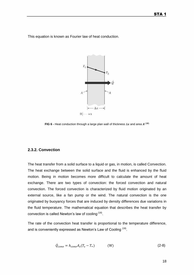
Where is the plane surface area, the difference between temperature of the
surfaces of the plane, the thickness of the material and the thermal conduction
coefficient, which is a property in each material (FIG 6) (18).
In the limit, ( ), the equation (2-6) reduces to the differential form.
(2-7)
STA 1
18
This equation is known as Fourier law of heat conduction.
FIG 6 - Heat conduction through a large plan wall of thickness and area
2.3.2. Convection
The heat transfer from a solid surface to a liquid or gas, in motion, is called Convection.
The heat exchange between the solid surface and the fluid is enhanced by the fluid
motion. Being in motion becomes more difficult to calculate the amount of heat
exchange. There are two types of convection: the forced convection and natural
convection. The forced convection is characterized by fluid motion originated by an
external source, like a fan pump or the wind. The natural convection is the one
originated by buoyancy forces that are induced by density differences due variations in
the fluid temperature. The mathematical equation that describes the heat transfer by
convection is called Newton’s law of cooling (18).
The rate of the convection heat transfer is proportional to the temperature difference,
and is conveniently expressed as Newton’s Law of Cooling (18).
(2-8)
STA 1
19
Where the is the convection heat transfer coefficient, the area of the surface
where the heat transfer occurs, the surface temperature and a temperature in
the fluid sufficiently far from the surface. Convection heat transfer coefficient is not a
specific property of a fluid. This parameter depends on the fluid properties, surface
geometry and bulk fluid velocity (18).
2.3.3. Thermal radiation
Thermal Radiation is the energy emitted by a body in the form of electromagnetic
waves, at a determined temperature. The heat transfer by radiation is the fastest
energy (at the speed of light), and do not requires an intervening medium to transfer
energy, unlike conduction and convection. All bodies, at a temperature above absolute
zero, emits thermal radiation (18).
The rate of radiation that can be emitted from a surface, at temperature , can be
determined from the Stefan–Boltzmann law ( ) (18).
(2-9)
Where the is the Stefan-Boltzmann constant, the surface area and ε the emissivity
of the surface ( ).
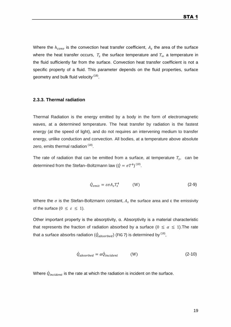
Other important property is the absorptivity, α. Absorptivity is a material characteristic
that represents the fraction of radiation absorbed by a surface ( ).The rate
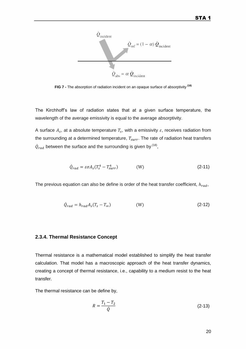
that a surface absorbs radiation ( ) (FIG 7) is determined by (18),
(2-10)
Where is the rate at which the radiation is incident on the surface.
STA 1
20
FIG 7 - The absorption of radiation incident on an opaque surface of absorptivity (18)
The Kirchhoff’s law of radiation states that at a given surface temperature, the
wavelength of the average emissivity is equal to the average absorptivity.
A surface , at a absolute temperature , with a emissivity , receives radiation from
the surrounding at a determined temperature, . The rate of radiation heat transfers
between the surface and the surrounding is given by (18),
(2-11)
The previous equation can also be define is order of the heat transfer coefficient, ,
(2-12)
2.3.4. Thermal Resistance Concept
Thermal resistance is a mathematical model established to simplify the heat transfer
calculation. That model has a macroscopic approach of the heat transfer dynamics,
creating a concept of thermal resistance, i.e., capability to a medium resist to the heat
transfer.
The thermal resistance can be define by,
(2-13)
STA 1
21
By rearranging the equations (2-6), (2-8) and (2-11), can be defined the conduction
resistance ( ), the convection resistance ( ) and the radiation resistance
( ).
For defining the conduction resistance, where is the thickness of the material,
(2-14)
(2-15)
The convection resistance,
(2-16)
and The radiation resistance,
(2-17)
In analogy the thermal resistance behaves as electric resistor, the series and parallel
arrangements of resistances are treated in the same way.
(2-18)
(2-19)
STA 1
22
2.4. PROCESS CONTROL
Process control is a group of techniques, with the purpose of accomplish and maintain
a desired state, responding to any exterior changes.
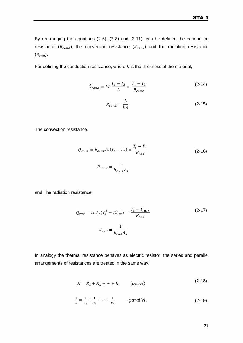
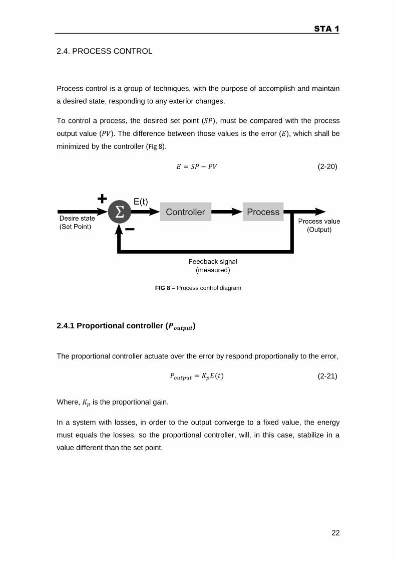
To control a process, the desired set point ( ), must be compared with the process
output value ( ). The difference between those values is the error ( ), which shall be
minimized by the controller (Fig 8).
(2-20)
FIG 8 – Process control diagram
2.4.1 Proportional controller ( )
The proportional controller actuate over the error by respond proportionally to the error,
(2-21)
Where, is the proportional gain.
In a system with losses, in order to the output converge to a fixed value, the energy
must equals the losses, so the proportional controller, will, in this case, stabilize in a
value different than the set point.
STA 1
23
2.4.2 Integrative controller ( )
The integrative controller will sum the error over time, increasing the action on the
process variable. This value should converge to the setpoint due the losses.
(2-22)
The integrative controller will always pass over the set point value (overshoot), the
action on the process will only be reversed when the sum of the negative error equals
the sum of the positive errors. The integral gain ( ) will determine the level of
overshoot.
2.4.3 Derivative controller ( )
The derivative controller ( ), is a controller that respond to the changes of the
error value. This controller has a fast reaction to rapid changes in the system (set point
and process values).
(2-23)
Where, is the derivative gain.
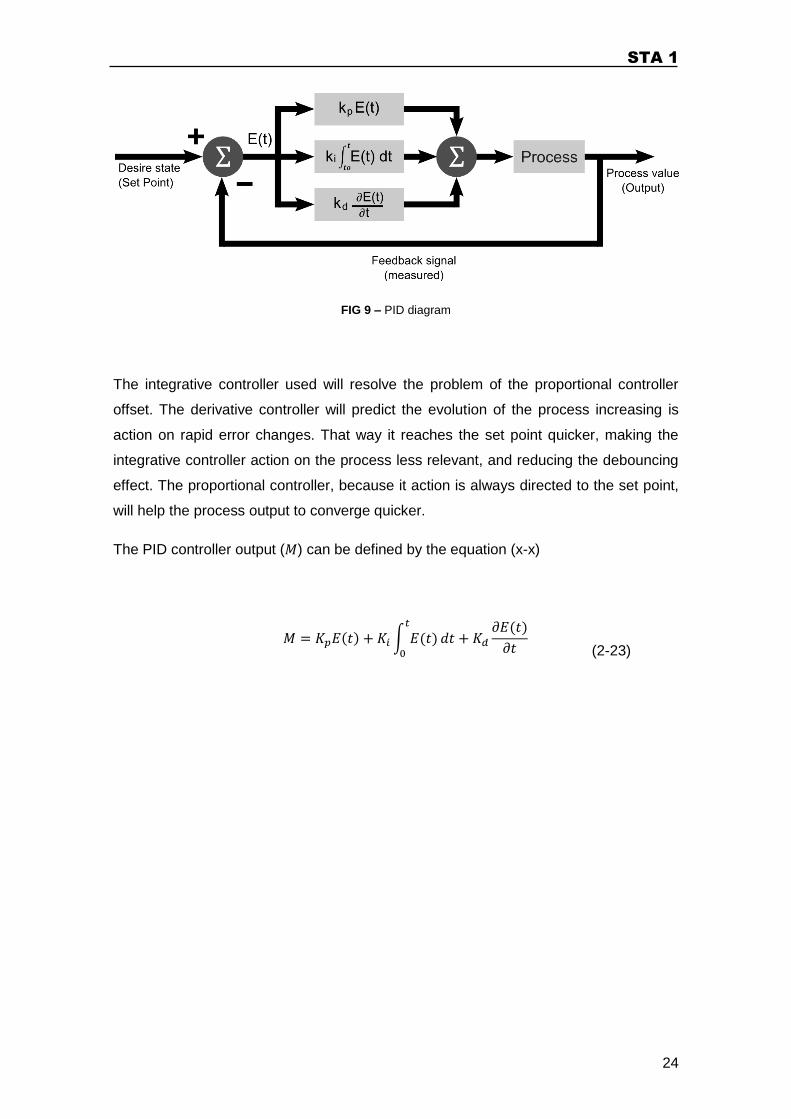
2.4.4 PID Controller
The PID controller (proportional, integrator and derivative), combine the tree previous
controllers (Fig 9) in order answer to the problems of each.
STA 1
24
FIG 9 – PID diagram
The integrative controller used will resolve the problem of the proportional controller
offset. The derivative controller will predict the evolution of the process increasing is
action on rapid error changes. That way it reaches the set point quicker, making the
integrative controller action on the process less relevant, and reducing the debouncing
effect. The proportional controller, because it action is always directed to the set point,
will help the process output to converge quicker.
The PID controller output ( ) can be defined by the equation (x-x)
(2-23)
STA 1
25
3. STA1 OVERVIEW
The STA Project pretends create a complete suit solution that provides a safer journey
to Alpinism practice above 7000m.
In the first phase of STA Project, it is intended to study and develop a hi-tech mitt that
will have an active heat control, so that high altitude alpinism could be a better
experience. The high-tech mitt is composed by two main parts: the mitt itself, and an
electronic thermal control system.
During the climbing of the mountain, symptoms related with the ascent and the low
temperatures appear gradually and the heat dissipated by the hand reduces.
Consequently it is created a gap between the optimal temperature (set point
temperature) and the natural temperature inside the mitt (temperature inside the mitt
without the usage of any control system). If the temperature rises, there will be an
increase of perspiration, increasing the dehydration, and if the temperature becomes
too low, there will increase the vasoconstriction effect. It is in this stage that the
electronic control system will act as a body temperature stabilizer. The usage of a
temperature control system can reduce the settlement velocity of the symptoms,
reducing the risk of frostbite condition.
The professional alpinist João Garcia had an important role in the decisions made. He
reported the problems that he faced and pointed aspects that can lead to the success
of this application.
All the calculus and considerations for the design of the mitt solution were made for an
altitude of , an exterior temperature of and a wind of .
STA 1
26
4. MATERIALS
Today’s alpinism equipment (apparel and mitt) consists of a simple structure, normally
composed by an outer layer of resistant fabric, a lining of polyester fibber and between
those, two layers of filling plumes, making the equipment very light. One of the major
problems of this equipment is that the thermal isolation is guaranteed by air space, so
when compressed the isolation is lost, making the alpinist lose a large quantity of body
heat.
At high altitude the environment temperature is very low. This environmental factor has
an effect on air humidity. The humidity levels become very low, because at very low
temperatures the water turns into snow.
4.1. MULTILAYER INSULATION STRUCTURE
In 1895 the explorers Fridtjof Nansen and Hjalmar Johansen went to an expedition to
the North Pole. They were lost, due to the movement of the polar cap, but survived in
the polar circle for four months, twice the time originally planned. At the time they were
trying a new strategy to fight the arctic cold, a multi layer insulation structure, and with
their unexpected adventure they prove its effectiveness (19).
The multilayer structure insulation proved to be more efficient then the insulation
materials used until then (wool, animal skin, etc.) due to the presence of air between
each layer (“dead air”). That air difficult the air flow inside the insulation structure,
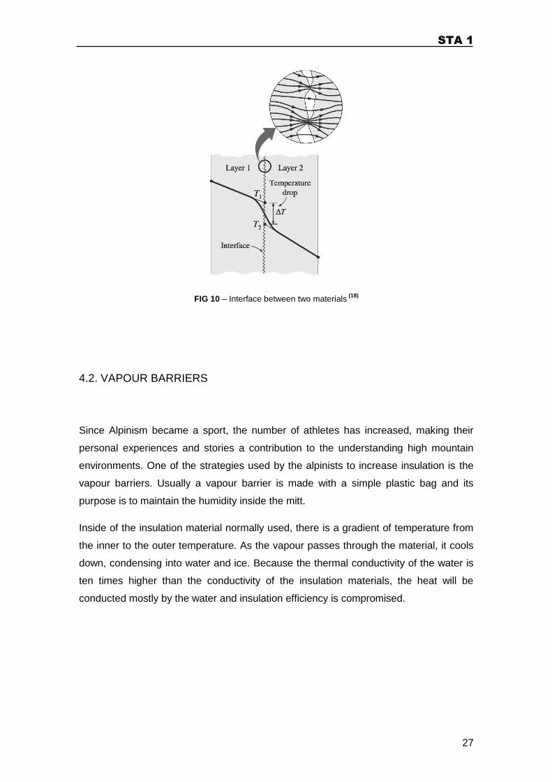
preventing the heat to escape. Other positive aspect is the thermal contact resistance
(FIG 10), i.e., the heat conduction trough the layers reduces due to the imperfect
thermal contact.
STA 1
27
FIG 10 – Interface between two materials (18)
4.2. VAPOUR BARRIERS
Since Alpinism became a sport, the number of athletes has increased, making their
personal experiences and stories a contribution to the understanding high mountain
environments. One of the strategies used by the alpinists to increase insulation is the
vapour barriers. Usually a vapour barrier is made with a simple plastic bag and its
purpose is to maintain the humidity inside the mitt.
Inside of the insulation material normally used, there is a gradient of temperature from
the inner to the outer temperature. As the vapour passes through the material, it cools
down, condensing into water and ice. Because the thermal conductivity of the water is
ten times higher than the conductivity of the insulation materials, the heat will be
conducted mostly by the water and insulation efficiency is compromised.
STA 1
28
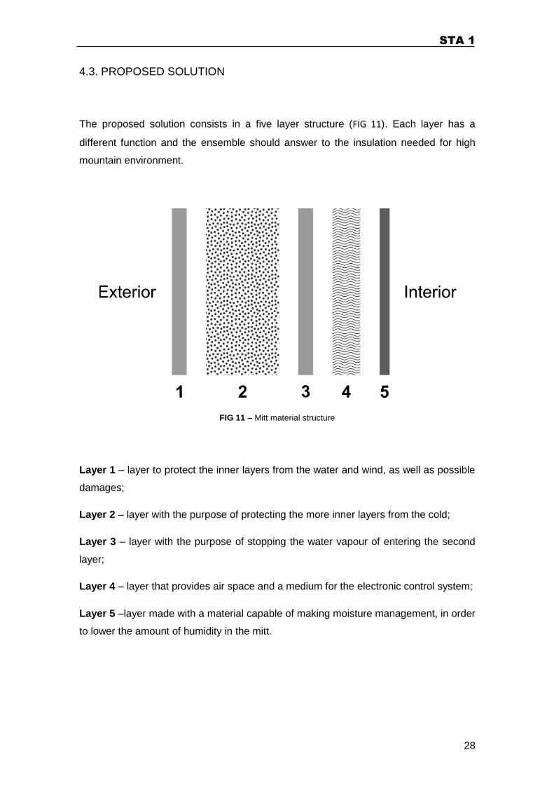
4.3. PROPOSED SOLUTION
The proposed solution consists in a five layer structure (FIG 11). Each layer has a
different function and the ensemble should answer to the insulation needed for high
mountain environment.
FIG 11 – Mitt material structure
Layer 1 – layer to protect the inner layers from the water and wind, as well as possible
damages;
Layer 2 – layer with the purpose of protecting the more inner layers from the cold;
Layer 3 – layer with the purpose of stopping the water vapour of entering the second
layer;
Layer 4 – layer that provides air space and a medium for the electronic control system;
Layer 5 –layer made with a material capable of making moisture management, in order
to lower the amount of humidity in the mitt.
STA 1
29
4.4. TYPES OF MATERIALS
4.4.1. Water Proof Fabrics (Layer 1 and 3)
In the high altitude environment the air is very dry, and the temperature is always below
the freezing point. The selected fabric should be totally impermeable and light, there is
no need for an expensive fabric with a complex structure. The TABLE 3 shows some of
the available materials in the market.
Material Characteristics
Cordura® UltraLight Fabric
Resistance to tears, scuffs and abrasion.
High tenacity filaments
Light
GORE-TEX® Moister vapour escapes
Rain snow and wind stay out
Polyester Rip Stop Fabric
Water Resistant
Not breathable
Light weight
NanoSphere® Water and dirt repelling
Light weight
3XDRY® Water and dirt repelling
Absolve interior humidity
FluoroFree™
Water and dirt repelling
Light weight
Bluesign® standard
TABLE 2 - Waterproof materials available
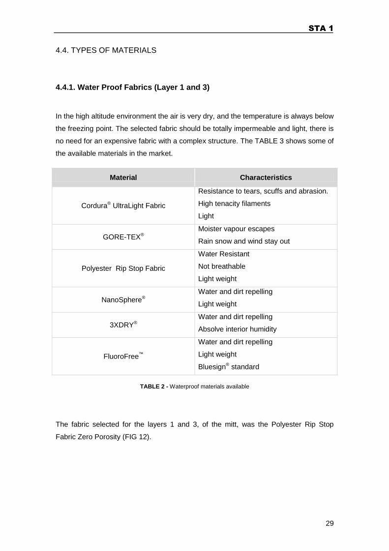
The fabric selected for the layers 1 and 3, of the mitt, was the Polyester Rip Stop
Fabric Zero Porosity (FIG 12).
STA 1
30
FIG 12 – Rip Stop Fabric4
Rip Stop Fabric has the feature of being made with a special reinforcing technique.
This technique consists of creating a mesh with strategic strong points that prevent the
fabric of tearing or ripping itself. There are several types of Rip Stop and for this project
it will be considered only the one that has zero porosity. Rip Stop Fabric with zero
porosity is made with very thin fibbers and a tight weaving. This way, it becomes even
lighter and absolutely waterproof. The application of Rip Stop Fabric is commonly seen
in parachutes and hot air balloons4.
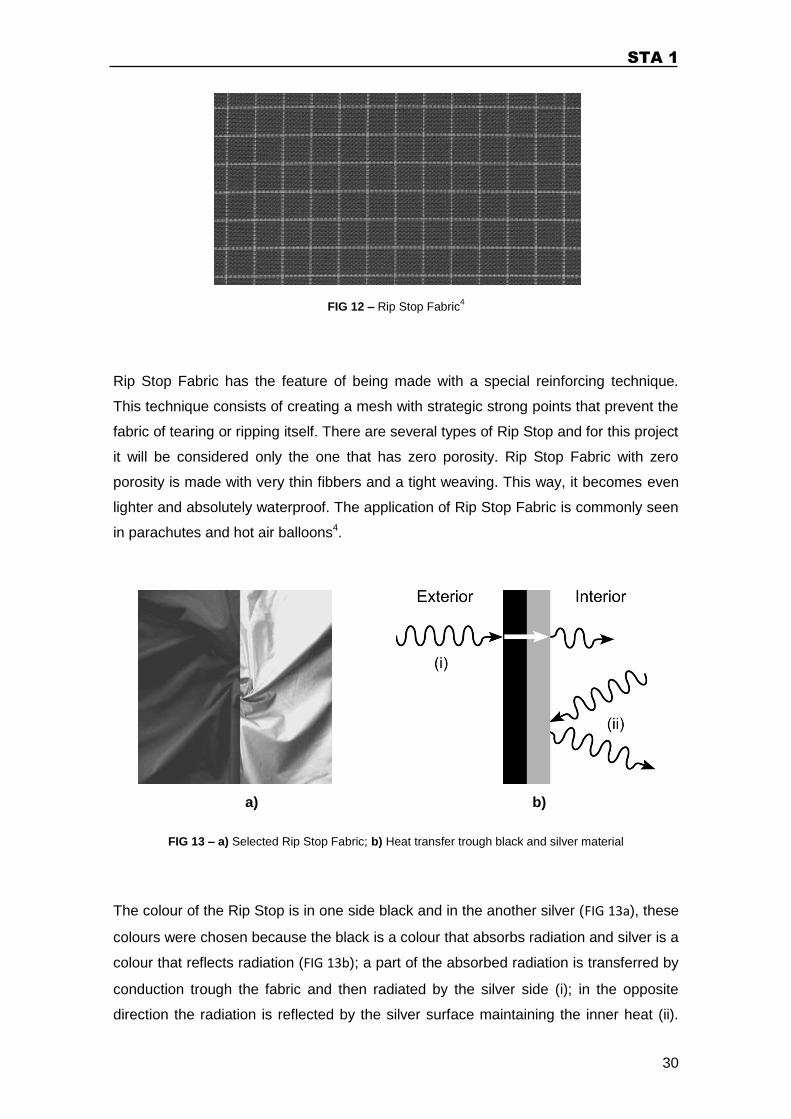
FIG 13 – a) Selected Rip Stop Fabric; b) Heat transfer trough black and silver material
The colour of the Rip Stop is in one side black and in the another silver (FIG 13a), these
colours were chosen because the black is a colour that absorbs radiation and silver is a
colour that reflects radiation (FIG 13b); a part of the absorbed radiation is transferred by
conduction trough the fabric and then radiated by the silver side (i); in the opposite
direction the radiation is reflected by the silver surface maintaining the inner heat (ii).
a) b)
STA 1
31
This principle is used in the satellite insulation, because in space all the heat transfer is
made by radiation.
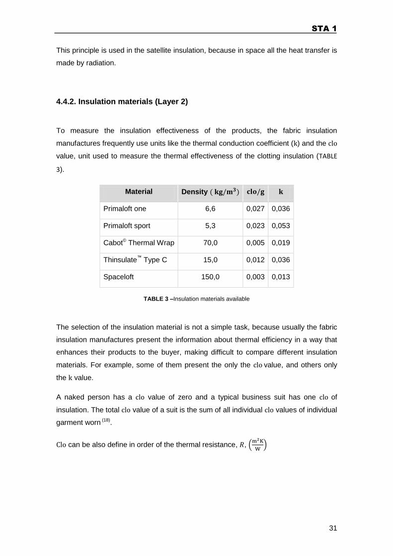
4.4.2. Insulation materials (Layer 2)
To measure the insulation effectiveness of the products, the fabric insulation
manufactures frequently use units like the thermal conduction coefficient ( ) and the
value, unit used to measure the thermal effectiveness of the clotting insulation (TABLE
3).
Material Density
Primaloft one 6,6 0,027 0,036
Primaloft sport 5,3 0,023 0,053
Cabot© Thermal Wrap 70,0 0,005 0,019
Thinsulate™ Type C 15,0 0,012 0,036
Spaceloft 150,0 0,003 0,013
TABLE 3 –Insulation materials available
The selection of the insulation material is not a simple task, because usually the fabric
insulation manufactures present the information about thermal efficiency in a way that
enhances their products to the buyer, making difficult to compare different insulation
materials. For example, some of them present the only the value, and others only
the value.
A naked person has a clo value of zero and a typical business suit has one clo of
insulation. The total clo value of a suit is the sum of all individual clo values of individual
garment worn (18).
Clo can be also define in order of the thermal resistance, ,

STA 1
32
(4-1)
The natural choice would be selecting the material with the highest thermal conduction
coefficient ( ). The fabrics with the highest value were the Aerogel fabrics (Cabot©
Thermal Wrap and Spaceloft).
Aerogel material is the lightest and most insulating material on earth, so it would be a
logical choice, but Aerogel material is a brittle material. Therefore, the Aerogel fabric is
composed by a support fabric coated with Aerogel material, minimizing the damage in
the Aerogel in the fabric. When the Aerogel cracks it becomes dust and fell out the
fabric, so the amount of Aerogel material in the fabric reduces, losing its thermal
efficiency. The Support fabric is a non woven fabric with a low compression coefficient,
but makes it heavier.
The weight is a very important factor in Alpinism. So, although we could provide
enough insulation with a thin Aerogel fabric, it still would be heavier than other
solutions available in the market, and the Aerogel fabric will always require a fabric
capable of containing the loosed particles, in order to prevent the inhalation of them by
the alpinist. To analyze correctly which insulation material would be more appropriate,
three parameters were considered: the density of the material, the of fabric and
the value. Analysing the weight needed to assure 1clo of insulation per square meter,
the material that can provide the best amount of insulation with less impact on the
overall weight is the Primaloft One (TABLE 4).
Material Mass (g) to achieve
of insulation
Primaloft one 37,0
Primaloft sport 43,5
Cabot© Thermal Wrap 200,0
Thinsulate™ Type C 83,3
Spaceloft 294,1
TABLE 4 - Mass (g) to achieve of insulation, for each insulation material
STA 1
33
In sum, because the application must be the lightest possible and the volume is not a
problem, was chosen the Primaloft One.
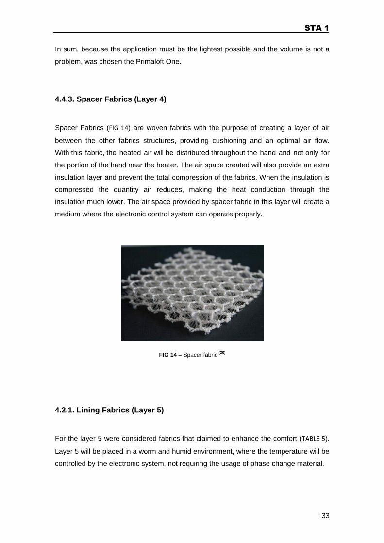
4.4.3. Spacer Fabrics (Layer 4)
Spacer Fabrics (FIG 14) are woven fabrics with the purpose of creating a layer of air
between the other fabrics structures, providing cushioning and an optimal air flow.
With this fabric, the heated air will be distributed throughout the hand and not only for
the portion of the hand near the heater. The air space created will also provide an extra
insulation layer and prevent the total compression of the fabrics. When the insulation is
compressed the quantity air reduces, making the heat conduction through the
insulation much lower. The air space provided by spacer fabric in this layer will create a
medium where the electronic control system can operate properly.
FIG 14 – Spacer fabric (20)
4.2.1. Lining Fabrics (Layer 5)
For the layer 5 were considered fabrics that claimed to enhance the comfort (TABLE 5).
Layer 5 will be placed in a worm and humid environment, where the temperature will be
controlled by the electronic system, not requiring the usage of phase change material.
STA 1
34
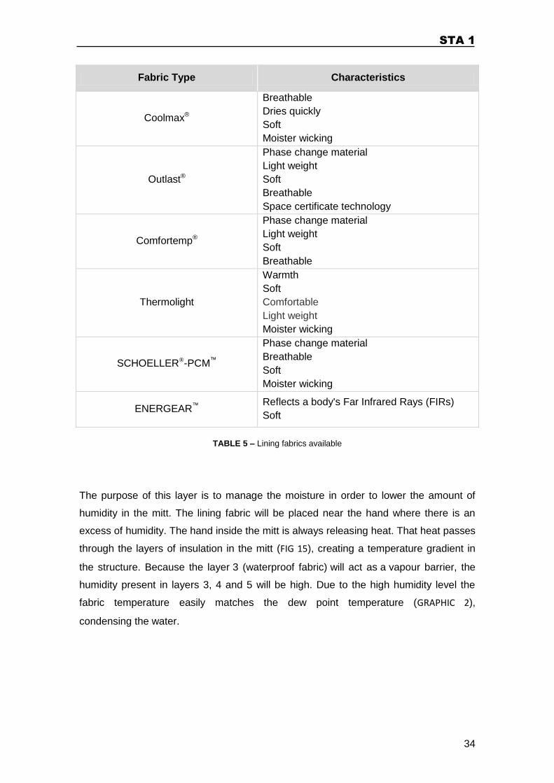
Fabric Type Characteristics
Coolmax®
Breathable
Dries quickly
Soft
Moister wicking
Outlast®
Phase change material
Light weight
Soft
Breathable
Space certificate technology
Comfortemp®
Phase change material
Light weight
Soft
Breathable
Thermolight
Warmth
Soft
Comfortable
Light weight
Moister wicking
SCHOELLER®-PCM™
Phase change material
Breathable
Soft
Moister wicking
ENERGEAR™ Reflects a body's Far Infrared Rays (FIRs)
Soft
TABLE 5 – Lining fabrics available
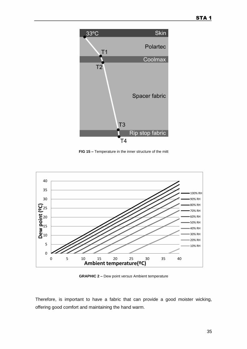
The purpose of this layer is to manage the moisture in order to lower the amount of
humidity in the mitt. The lining fabric will be placed near the hand where there is an
excess of humidity. The hand inside the mitt is always releasing heat. That heat passes
through the layers of insulation in the mitt (FIG 15), creating a temperature gradient in
the structure. Because the layer 3 (waterproof fabric) will act as a vapour barrier, the
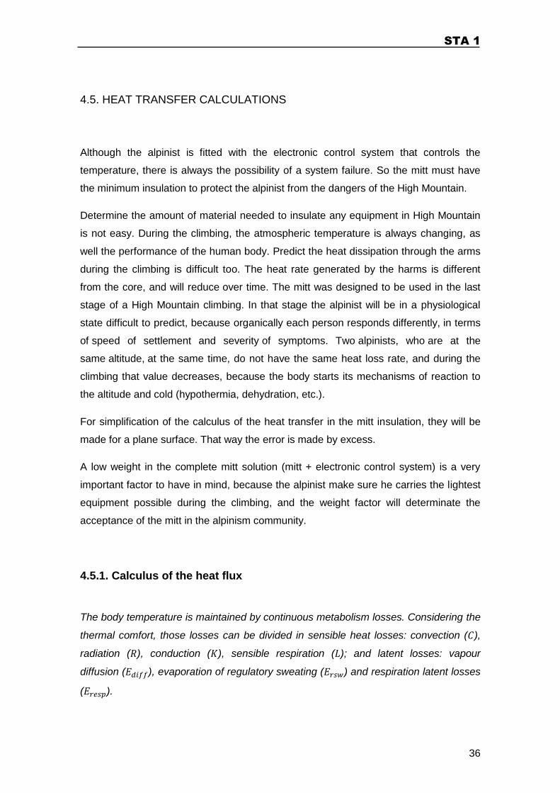
humidity present in layers 3, 4 and 5 will be high. Due to the high humidity level the
fabric temperature easily matches the dew point temperature (GRAPHIC 2),
condensing the water.
STA 1
35
FIG 15 – Temperature in the inner structure of the mitt
GRAPHIC 2 – Dew point versus Ambient temperature
Therefore, is important to have a fabric that can provide a good moister wicking,
offering good comfort and maintaining the hand warm.
0
5
10
15
20
25
30
35
40
0 5 10 15 20 25 30 35 40
Dew
po
int
(ºC
)
Ambient temperature(ºC)
100% RH
90% RH
80% RH
70% RH
60% RH
50% RH
40% RH
30% RH
20% RH
10% RH
STA 1
36
4.5. HEAT TRANSFER CALCULATIONS
Although the alpinist is fitted with the electronic control system that controls the
temperature, there is always the possibility of a system failure. So the mitt must have
the minimum insulation to protect the alpinist from the dangers of the High Mountain.
Determine the amount of material needed to insulate any equipment in High Mountain
is not easy. During the climbing, the atmospheric temperature is always changing, as
well the performance of the human body. Predict the heat dissipation through the arms
during the climbing is difficult too. The heat rate generated by the harms is different
from the core, and will reduce over time. The mitt was designed to be used in the last
stage of a High Mountain climbing. In that stage the alpinist will be in a physiological
state difficult to predict, because organically each person responds differently, in terms
of speed of settlement and severity of symptoms. Two alpinists, who are at the
same altitude, at the same time, do not have the same heat loss rate, and during the
climbing that value decreases, because the body starts its mechanisms of reaction to
the altitude and cold (hypothermia, dehydration, etc.).
For simplification of the calculus of the heat transfer in the mitt insulation, they will be
made for a plane surface. That way the error is made by excess.
A low weight in the complete mitt solution (mitt + electronic control system) is a very
important factor to have in mind, because the alpinist make sure he carries the lightest
equipment possible during the climbing, and the weight factor will determinate the
acceptance of the mitt in the alpinism community.
4.5.1. Calculus of the heat flux
The body temperature is maintained by continuous metabolism losses. Considering the
thermal comfort, those losses can be divided in sensible heat losses: convection ( ),
radiation ( ), conduction ( ), sensible respiration ( ); and latent losses: vapour
diffusion ( ), evaporation of regulatory sweating ( ) and respiration latent losses
( ).
STA 1
37
The equation that establish the mechanisms related to thermal comfort is (21),
(4-2)
Where , being is the heat balance, the metabolic heat, and the the
metabolic rate converted into work.
The values of latent losses are not considered for thermal insulation calculations; the
reason is because those losses came from a water phase change (liquid to vapour).
Considering that the quantity of condensed water in the mitt will stabilize, the flux of
vapour that is expelled from the mitt will be equal to the vapour expelled from the body,
so, the latent energy will be lost. The sensible respiration losses are not considered for
the insulation because the heat is expelled directly from the mouth. In the skin surface,
it will be considered only the losses by radiation and convection.
For the insulation calculus it was considered the metabolic rate of a man walking up a
grade of inclination, at in the standing position ( and
) (ANNEX A).
(4-3)
Where is the mechanical efficiency.
For knowing the value the other elements of the equation (4-2) must be
determined:
Vapour pressure ( )
Considering a ambient temperature ( ) of and a relative humidity of (typical
value in High Mountain environment, , during expedition), the saturation vapour
pressure can be calculated by the Magnus Tetens equation,
STA 1
38
(4-4)
From the relative humidity relation (2-1),
– Heat loss due to vapour diffusion through the skin (22)
(4-5)
– Heat loss due to evaporation of regulatory sweating from the skin (22)
(4-6)
– Heat loss respiration latent heat loss (22)
(4-7)
STA 1
39
– Sensible (dry) heat loss, respiration (23)
(4-8)
After gathering all the equation (4-2) values, the can be know calculated,
In this case,
(4-9)
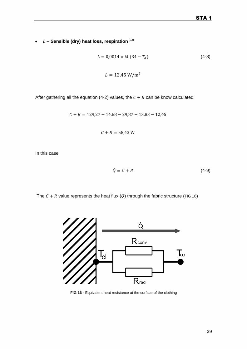
The value represents the heat flux ( ) through the fabric structure (FIG 16)
FIG 16 - Equivalent heat resistance at the surface of the clothing
STA 1
40
The heat resistance from the exterior of the clothing ( ), in this application, can be
defined in three different ways,
(4-10)
(4-11)
(4-12)
Where,
(4-13)
Combining the previous equations (4-11 and 4-12) the clothing temperature can be
determined,
(4-14)
In an iterative process using the equations (4-14), (4-15), (4-16), (4-17) and (4-18) was
determined the value of .
Convection ( )
(4-15)
STA 1
41
Where is the convection heat transfer coefficient (13) and the wind velocity
( ). To calculate the Convection it will be used the equation (4-16) (23)
(4-16)
Radiation ( )
(4-17)
Where is the radiation heat transfer coefficient (18) and the emissivity ( ), and
the Stefan-Boltzmann constant.
(4-18)
4.5.2. Calculus of the insulation thickness of the mitt (general)
In an expedition the climbers use a pair of gloves inside the mitt to perform more
complex tasks like use an ice axe, drink water, eat, etc. For that reason, in the
insulation calculus, it will be considered a pair of gloves made of Polartec Classic
fabric, with .
Analysing the mitt fabric structure it was decided of not considering the layers 1, 3 and
5 to the insulation calculus, because their influence on the final result is negligible, due
to their characteristics, like a thin thickness (a fraction of a millimetre), and a value
much higher than usual value of the other materials.
STA 1
42
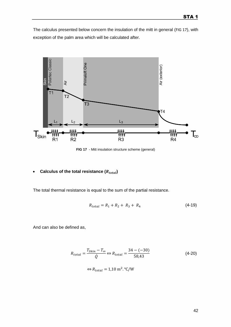
The calculus presented below concern the insulation of the mitt in general (FIG 17), with
exception of the palm area which will be calculated after.
FIG 17 - Mitt insulation structure scheme (general)
Calculus of the total resistance ( )
The total thermal resistance is equal to the sum of the partial resistance.
(4-19)
And can also be defined as,
(4-20)
STA 1
43
The values of the skin temperature and the exterior temperature are and ,
respectively.
Calculus of the resistance one ( )
The first material is the Polartec classic fabric that has a and a
material thickness of .
(4-21)
Calculus of the resistance two ( )
This layer has the spacer fabric, to simplify the calculus it will be considered as an air
layer. The air has a value of and a
Applying the equation (2-14),
Calculus of and
Using the concept of thermal resistance, equation (2-13), the temperature at the fabric
surface can be calculated,
(4-22)
STA 1
44
was already calculated
Calculus of the resistance four ( )
The resistance four ( ) is composed by the parallel of the convection and the radiation
resistance (FIG 16)
(4-23)
Calculus of the resistance three ( )
After gathering all the resistance values, the can be determine by the equation (4-19)
Calculus of the
The undefined thickness value of insulation is . This layer insulation thickness will
determinate the overall mitt insulation thickness.
The pretended insulation value can be determined trough the equation (2-15),
Were the value for the Primaloft One is
STA 1
45
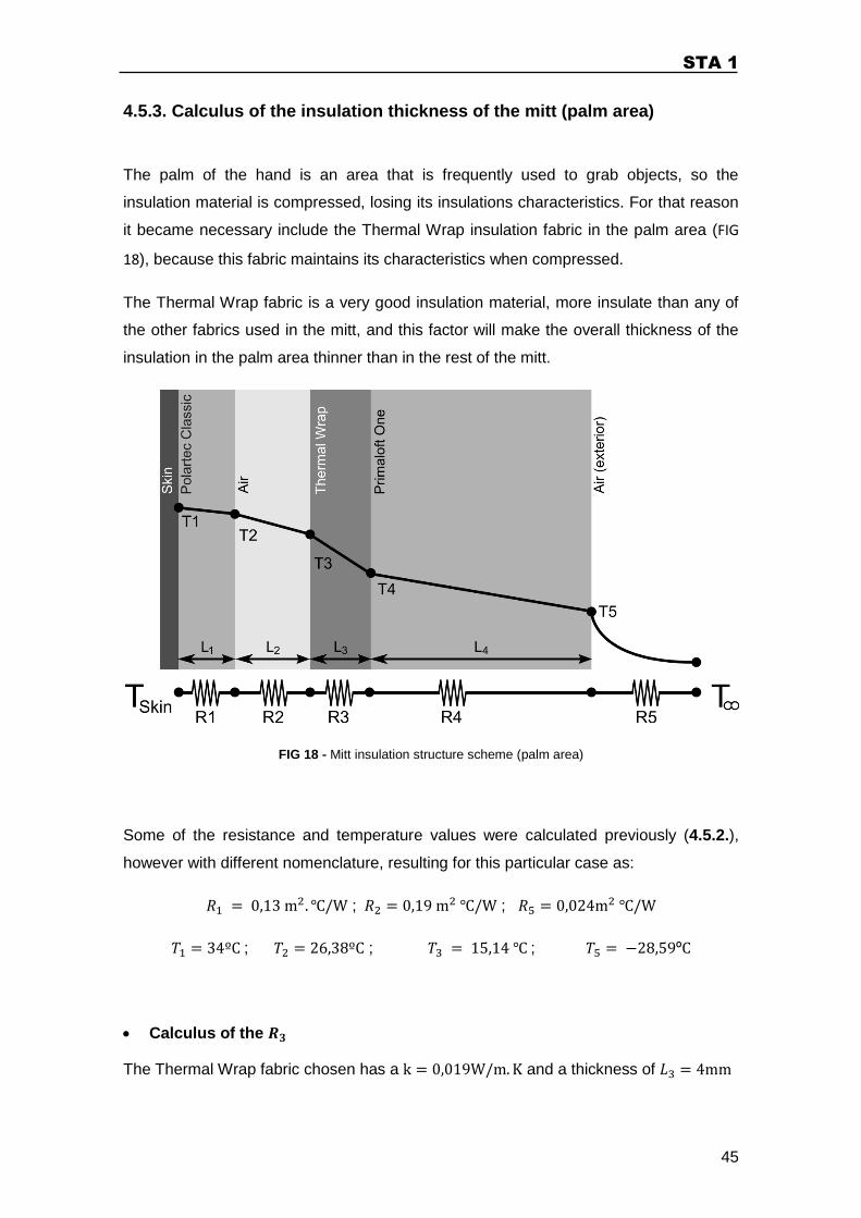
4.5.3. Calculus of the insulation thickness of the mitt (palm area)
The palm of the hand is an area that is frequently used to grab objects, so the
insulation material is compressed, losing its insulations characteristics. For that reason
it became necessary include the Thermal Wrap insulation fabric in the palm area (FIG
18), because this fabric maintains its characteristics when compressed.
The Thermal Wrap fabric is a very good insulation material, more insulate than any of
the other fabrics used in the mitt, and this factor will make the overall thickness of the
insulation in the palm area thinner than in the rest of the mitt.
FIG 18 - Mitt insulation structure scheme (palm area)
Some of the resistance and temperature values were calculated previously (4.5.2.),
however with different nomenclature, resulting for this particular case as:
; ;
; ; ;
Calculus of the
The Thermal Wrap fabric chosen has a and a thickness of
STA 1
46
(4-24)
Calculus of the
Applying the equation (4-22),
Calculus of the
After having and the resistance values calculated, the can be
determinate,
(4-25)
Calculus of the
The undefined thickness value of insulation is . This layer insulation thickness will
determinate the overall mitt insulation thickness.
For the palm area insulation the Primaloft One material has a thickness determined by
the equation (2-15),
(4-26)
STA 1
47
5. ELECTRONIC SYSTEM DEVELOPMENT
Alpinism is a sport practiced in a very harsh and demanding environment. During
workout is easy to feel high oscillations in the temperature, due to the heat dynamics of
the human body. That is why it is important to have a temperature control system to
compensate these oscillations and reduce the losses by minimizing the body
physiologic responses (sweat and vasoconstriction).
The solution found to control temperature was an electronic device that can respond to
the temperature changes inside the mitt.
The proposed electronic device is not the same for the two mitts, because there is a
higher percentage of right handed people, the human machine interface (HMI) is
placed only in one of the mitts. The HMI is placed in the left mitt in order to be operated
by the right hand.
The left mitt electronic device is composed by a microcontroller, human machine
interface (HMI) and a sensing, actuator and communication module (FIG 19). The right
mitt electronic device does not need the HMI module, the control parameters should be
transferred by the communication module.
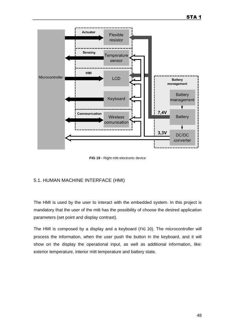
STA 1
48
FIG 19 - Right mitt electronic device
5.1. HUMAN MACHINE INTERFACE (HMI)
The HMI is used by the user to interact with the embedded system. In this project is
mandatory that the user of the mitt has the possibility of choose the desired application
parameters (set point and display contrast).
The HMI is composed by a display and a keyboard (FIG 20). The microcontroller will
process the information, when the user push the button in the keyboard, and it will
show on the display the operational input, as well as additional information, like:
exterior temperature, interior mitt temperature and battery state.
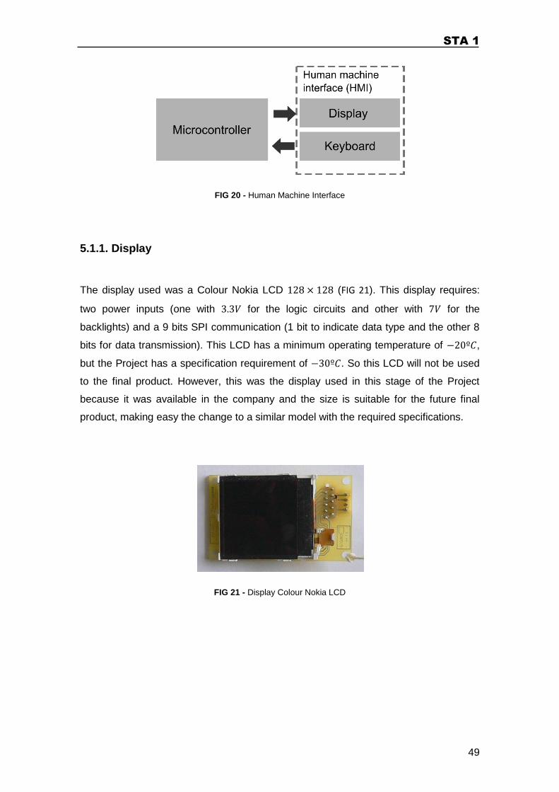
STA 1
49
FIG 20 - Human Machine Interface
5.1.1. Display
The display used was a Colour Nokia LCD (FIG 21). This display requires:
two power inputs (one with for the logic circuits and other with for the
backlights) and a 9 bits SPI communication (1 bit to indicate data type and the other 8
bits for data transmission). This LCD has a minimum operating temperature of ,
but the Project has a specification requirement of . So this LCD will not be used
to the final product. However, this was the display used in this stage of the Project
because it was available in the company and the size is suitable for the future final
product, making easy the change to a similar model with the required specifications.
FIG 21 - Display Colour Nokia LCD
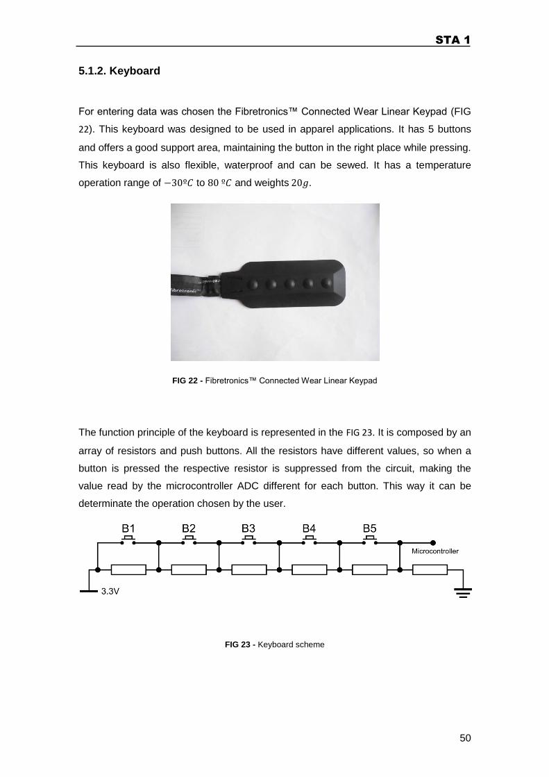
STA 1
50
5.1.2. Keyboard
For entering data was chosen the Fibretronics™ Connected Wear Linear Keypad (FIG
22). This keyboard was designed to be used in apparel applications. It has 5 buttons
and offers a good support area, maintaining the button in the right place while pressing.
This keyboard is also flexible, waterproof and can be sewed. It has a temperature
operation range of to and weights .
FIG 22 - Fibretronics™ Connected Wear Linear Keypad
The function principle of the keyboard is represented in the FIG 23. It is composed by an
array of resistors and push buttons. All the resistors have different values, so when a
button is pressed the respective resistor is suppressed from the circuit, making the
value read by the microcontroller ADC different for each button. This way it can be
determinate the operation chosen by the user.
FIG 23 - Keyboard scheme
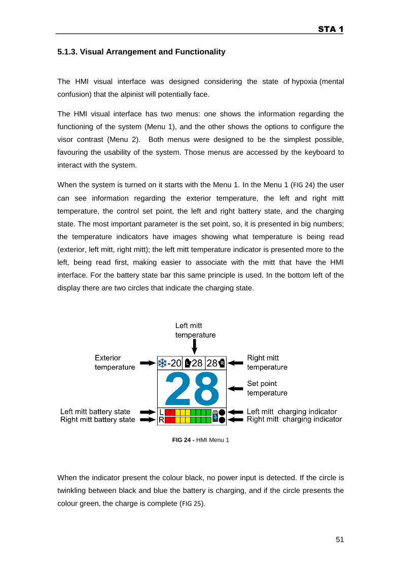
STA 1
51
5.1.3. Visual Arrangement and Functionality
The HMI visual interface was designed considering the state of hypoxia (mental
confusion) that the alpinist will potentially face.
The HMI visual interface has two menus: one shows the information regarding the
functioning of the system (Menu 1), and the other shows the options to configure the
visor contrast (Menu 2). Both menus were designed to be the simplest possible,
favouring the usability of the system. Those menus are accessed by the keyboard to
interact with the system.
When the system is turned on it starts with the Menu 1. In the Menu 1 (FIG 24) the user
can see information regarding the exterior temperature, the left and right mitt
temperature, the control set point, the left and right battery state, and the charging
state. The most important parameter is the set point, so, it is presented in big numbers;
the temperature indicators have images showing what temperature is being read
(exterior, left mitt, right mitt); the left mitt temperature indicator is presented more to the
left, being read first, making easier to associate with the mitt that have the HMI
interface. For the battery state bar this same principle is used. In the bottom left of the
display there are two circles that indicate the charging state.
FIG 24 - HMI Menu 1
When the indicator present the colour black, no power input is detected. If the circle is
twinkling between black and blue the battery is charging, and if the circle presents the
colour green, the charge is complete (FIG 25).
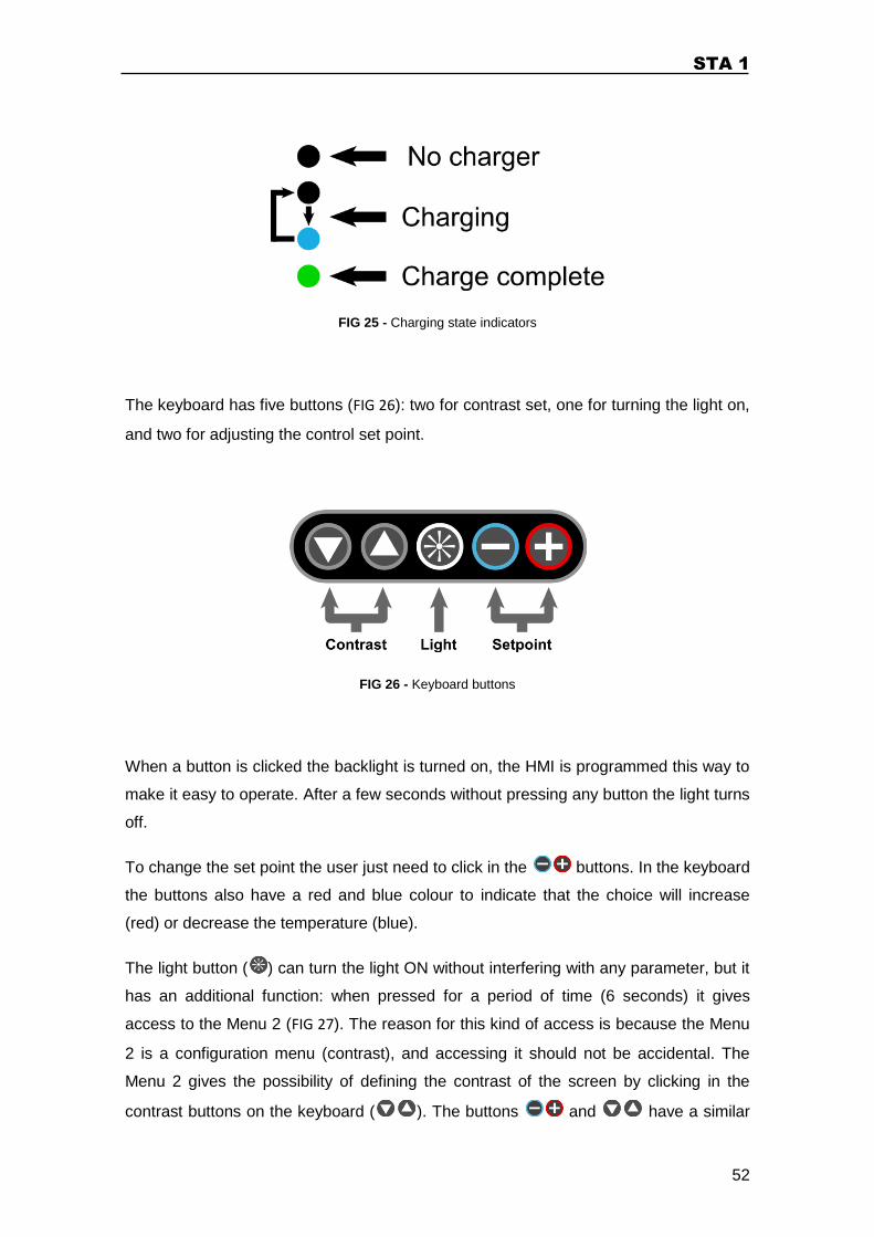
STA 1
52
FIG 25 - Charging state indicators
The keyboard has five buttons (FIG 26): two for contrast set, one for turning the light on,
and two for adjusting the control set point.
FIG 26 - Keyboard buttons
When a button is clicked the backlight is turned on, the HMI is programmed this way to
make it easy to operate. After a few seconds without pressing any button the light turns
off.
To change the set point the user just need to click in the buttons. In the keyboard
the buttons also have a red and blue colour to indicate that the choice will increase
(red) or decrease the temperature (blue).
The light button ( ) can turn the light ON without interfering with any parameter, but it
has an additional function: when pressed for a period of time (6 seconds) it gives
access to the Menu 2 (FIG 27). The reason for this kind of access is because the Menu
2 is a configuration menu (contrast), and accessing it should not be accidental. The
Menu 2 gives the possibility of defining the contrast of the screen by clicking in the
contrast buttons on the keyboard ( ). The buttons and have a similar
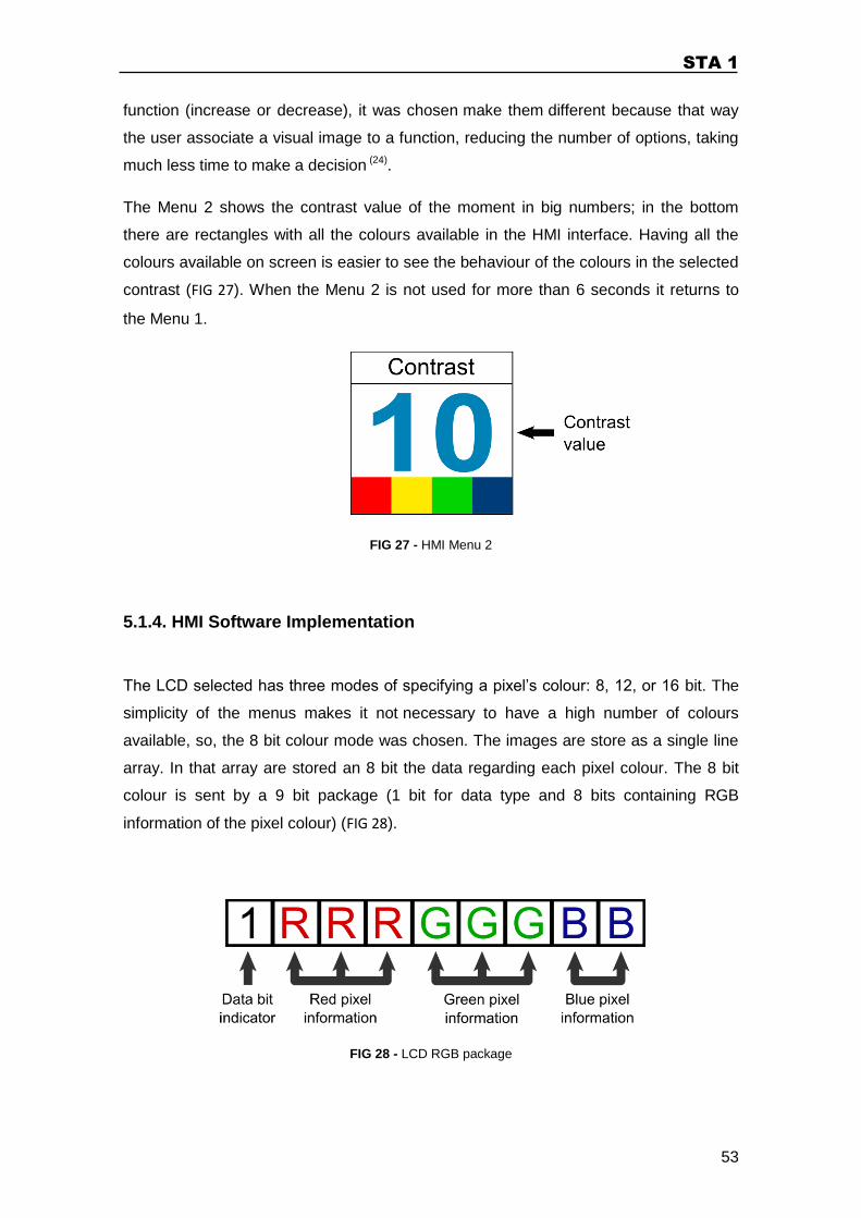
STA 1
53
function (increase or decrease), it was chosen make them different because that way
the user associate a visual image to a function, reducing the number of options, taking
much less time to make a decision (24).
The Menu 2 shows the contrast value of the moment in big numbers; in the bottom
there are rectangles with all the colours available in the HMI interface. Having all the
colours available on screen is easier to see the behaviour of the colours in the selected
contrast (FIG 27). When the Menu 2 is not used for more than 6 seconds it returns to
the Menu 1.
FIG 27 - HMI Menu 2
5.1.4. HMI Software Implementation
The LCD selected has three modes of specifying a pixel’s colour: 8, 12, or 16 bit. The
simplicity of the menus makes it not necessary to have a high number of colours
available, so, the 8 bit colour mode was chosen. The images are store as a single line
array. In that array are stored an 8 bit the data regarding each pixel colour. The 8 bit
colour is sent by a 9 bit package (1 bit for data type and 8 bits containing RGB
information of the pixel colour) (FIG 28).
FIG 28 - LCD RGB package
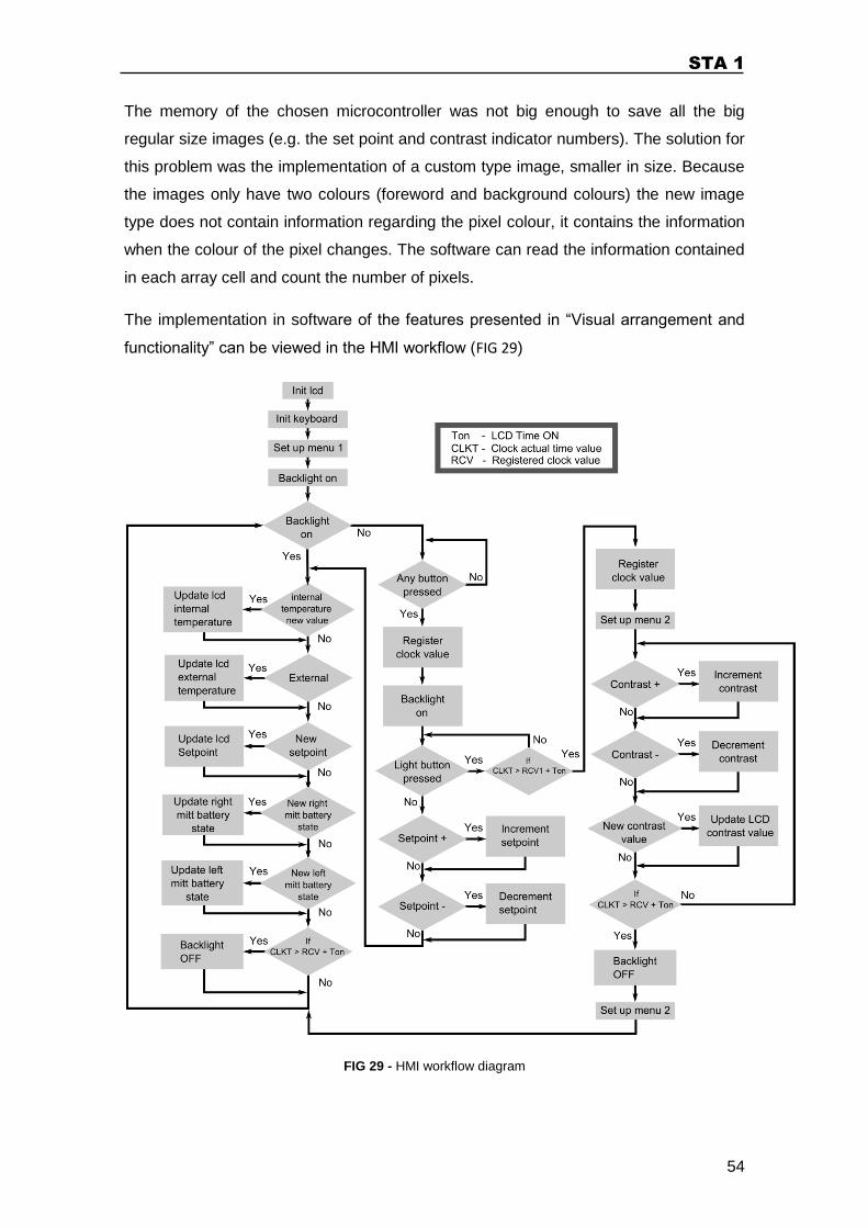
STA 1
54
The memory of the chosen microcontroller was not big enough to save all the big
regular size images (e.g. the set point and contrast indicator numbers). The solution for
this problem was the implementation of a custom type image, smaller in size. Because
the images only have two colours (foreword and background colours) the new image
type does not contain information regarding the pixel colour, it contains the information
when the colour of the pixel changes. The software can read the information contained
in each array cell and count the number of pixels.
The implementation in software of the features presented in “Visual arrangement and
functionality” can be viewed in the HMI workflow (FIG 29)
FIG 29 - HMI workflow diagram
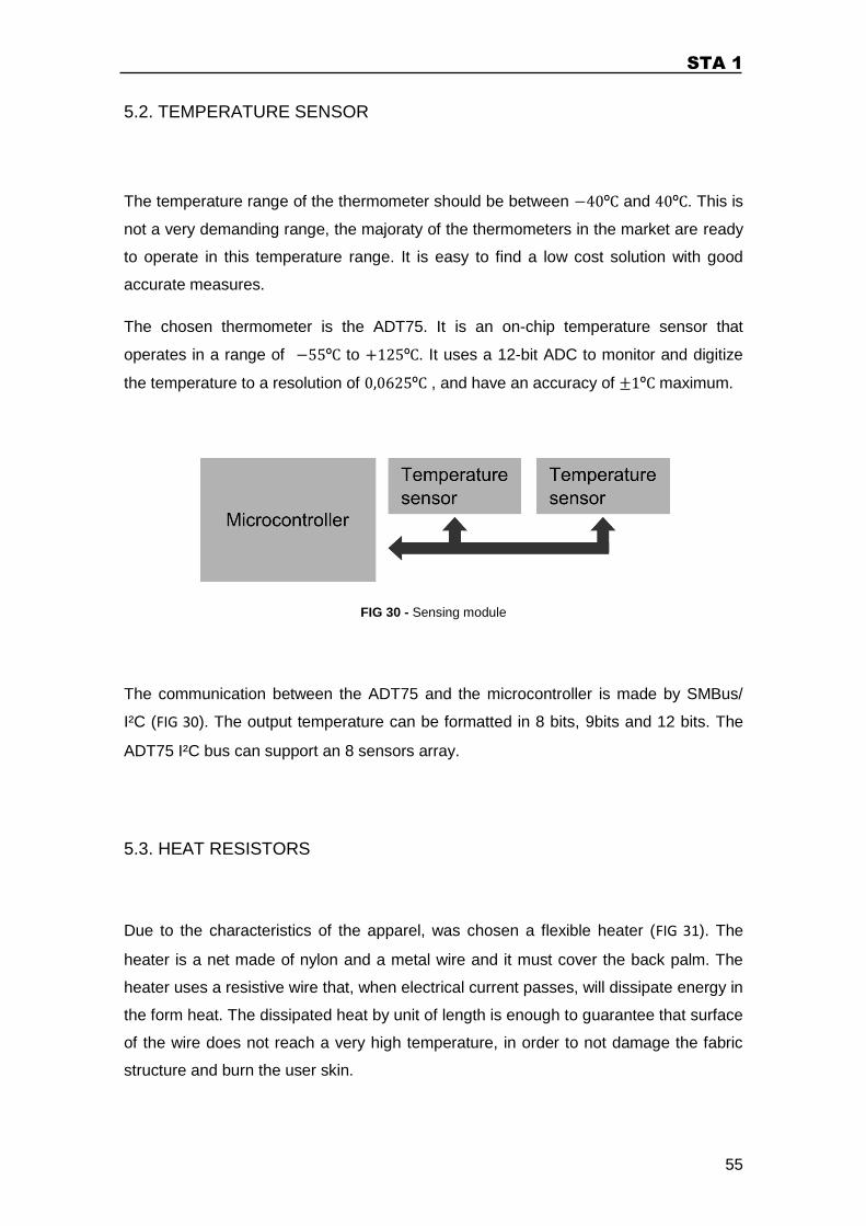
STA 1
55
5.2. TEMPERATURE SENSOR
The temperature range of the thermometer should be between and . This is
not a very demanding range, the majoraty of the thermometers in the market are ready
to operate in this temperature range. It is easy to find a low cost solution with good
accurate measures.
The chosen thermometer is the ADT75. It is an on-chip temperature sensor that
operates in a range of to . It uses a 12-bit ADC to monitor and digitize
the temperature to a resolution of , and have an accuracy of maximum.
FIG 30 - Sensing module
The communication between the ADT75 and the microcontroller is made by SMBus/
I²C (FIG 30). The output temperature can be formatted in 8 bits, 9bits and 12 bits. The
ADT75 I²C bus can support an 8 sensors array.
5.3. HEAT RESISTORS
Due to the characteristics of the apparel, was chosen a flexible heater (FIG 31). The
heater is a net made of nylon and a metal wire and it must cover the back palm. The
heater uses a resistive wire that, when electrical current passes, will dissipate energy in
the form heat. The dissipated heat by unit of length is enough to guarantee that surface
of the wire does not reach a very high temperature, in order to not damage the fabric
structure and burn the user skin.
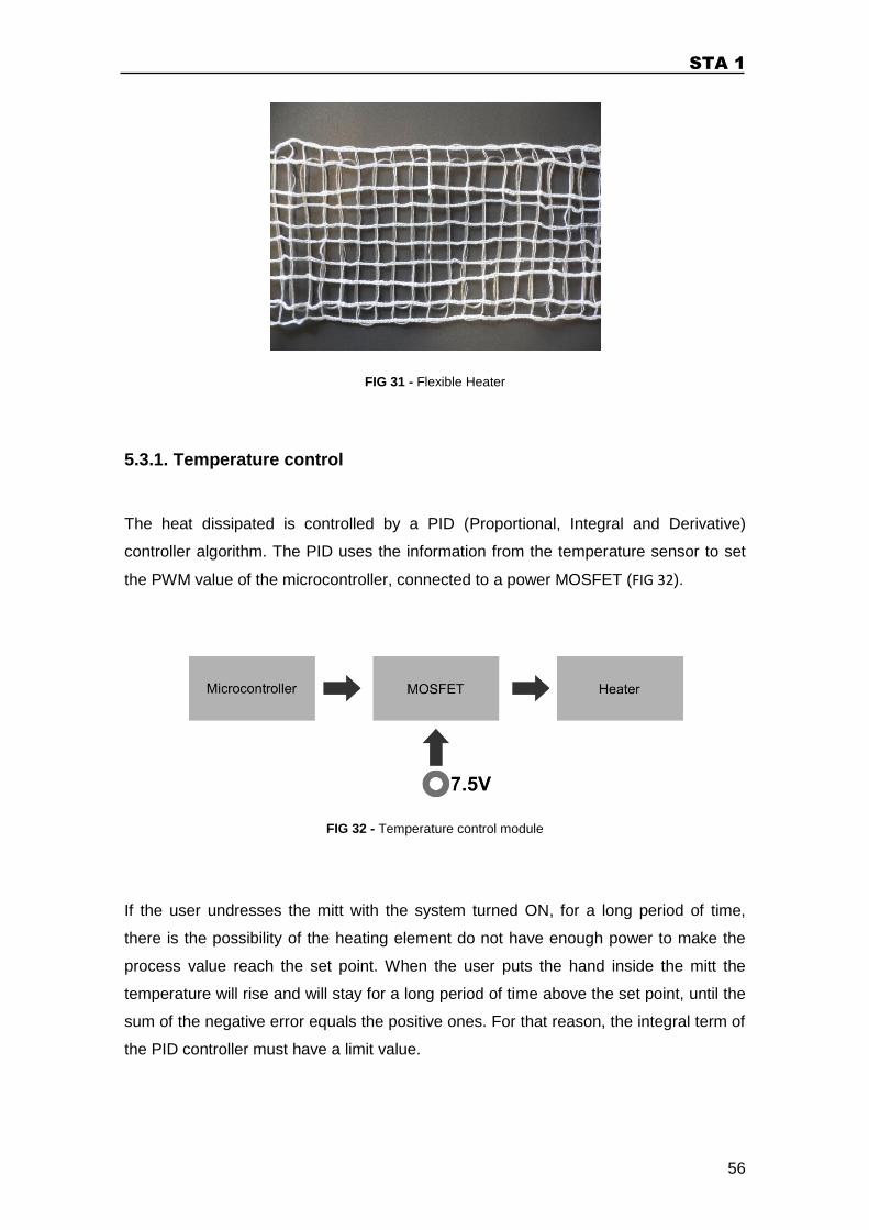
STA 1
56
FIG 31 - Flexible Heater
5.3.1. Temperature control
The heat dissipated is controlled by a PID (Proportional, Integral and Derivative)
controller algorithm. The PID uses the information from the temperature sensor to set
the PWM value of the microcontroller, connected to a power MOSFET (FIG 32).
FIG 32 - Temperature control module
If the user undresses the mitt with the system turned ON, for a long period of time,
there is the possibility of the heating element do not have enough power to make the
process value reach the set point. When the user puts the hand inside the mitt the
temperature will rise and will stay for a long period of time above the set point, until the
sum of the negative error equals the positive ones. For that reason, the integral term of
the PID controller must have a limit value.
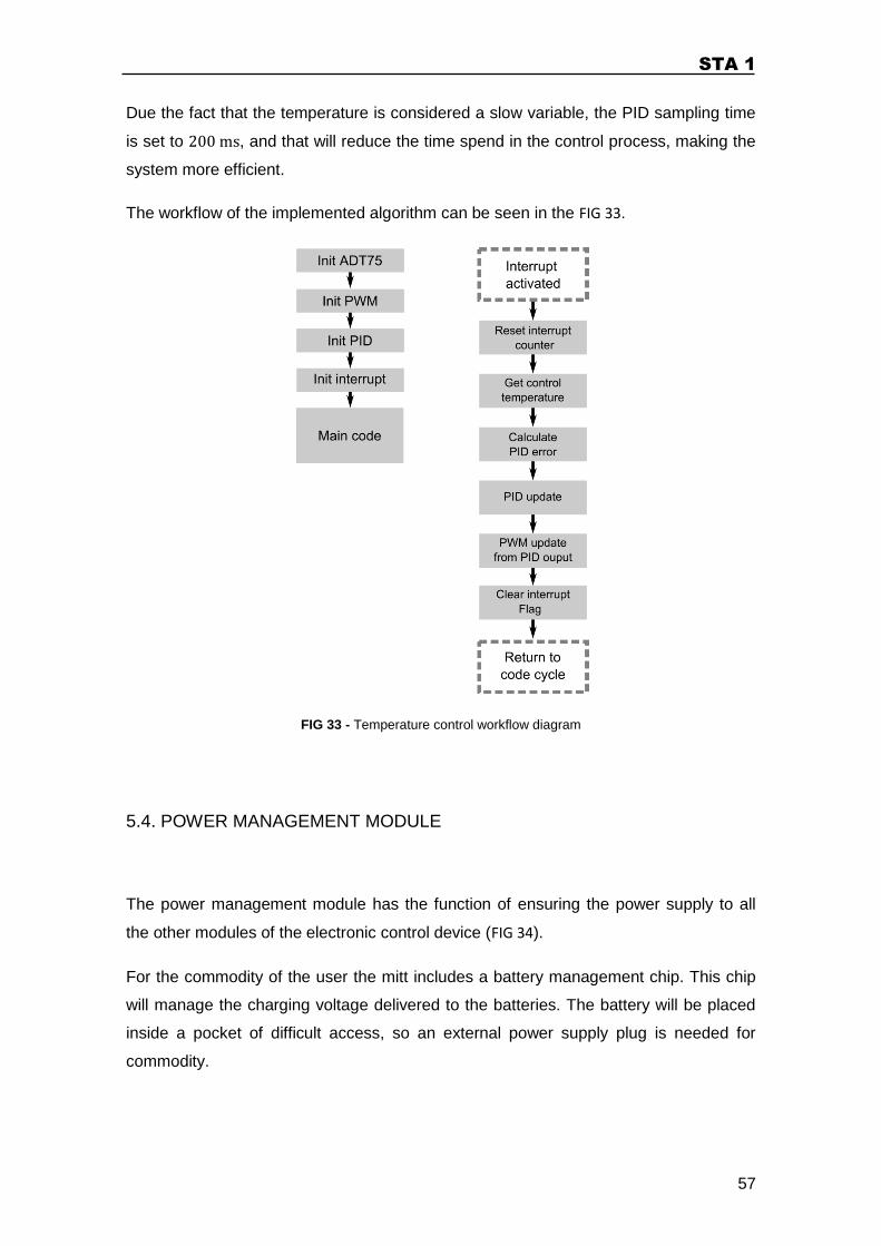
STA 1
57
Due the fact that the temperature is considered a slow variable, the PID sampling time
is set to , and that will reduce the time spend in the control process, making the
system more efficient.
The workflow of the implemented algorithm can be seen in the FIG 33.
FIG 33 - Temperature control workflow diagram
5.4. POWER MANAGEMENT MODULE
The power management module has the function of ensuring the power supply to all
the other modules of the electronic control device (FIG 34).
For the commodity of the user the mitt includes a battery management chip. This chip
will manage the charging voltage delivered to the batteries. The battery will be placed
inside a pocket of difficult access, so an external power supply plug is needed for
commodity.
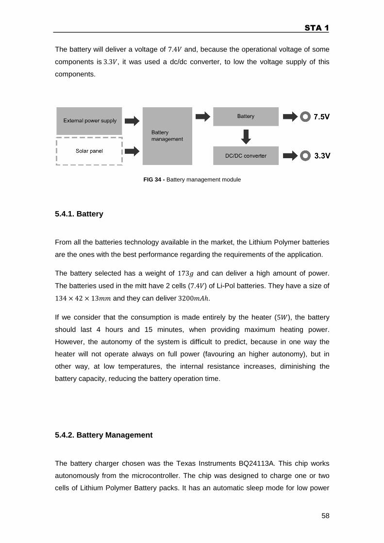
STA 1
58
The battery will deliver a voltage of and, because the operational voltage of some
components is , it was used a dc/dc converter, to low the voltage supply of this
components.
FIG 34 - Battery management module
5.4.1. Battery
From all the batteries technology available in the market, the Lithium Polymer batteries
are the ones with the best performance regarding the requirements of the application.
The battery selected has a weight of and can deliver a high amount of power.
The batteries used in the mitt have 2 cells ( ) of Li-Pol batteries. They have a size of
and they can deliver .
If we consider that the consumption is made entirely by the heater ( ), the battery
should last 4 hours and 15 minutes, when providing maximum heating power.
However, the autonomy of the system is difficult to predict, because in one way the
heater will not operate always on full power (favouring an higher autonomy), but in
other way, at low temperatures, the internal resistance increases, diminishing the
battery capacity, reducing the battery operation time.
5.4.2. Battery Management
The battery charger chosen was the Texas Instruments BQ24113A. This chip works
autonomously from the microcontroller. The chip was designed to charge one or two
cells of Lithium Polymer Battery packs. It has an automatic sleep mode for low power
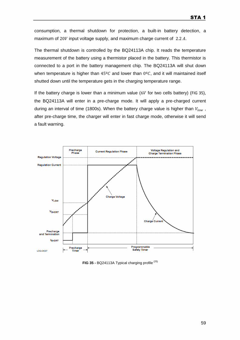
STA 1
59
consumption, a thermal shutdown for protection, a built-in battery detection, a
maximum of input voltage supply, and maximum charge current of .
The thermal shutdown is controlled by the BQ24113A chip. It reads the temperature
measurement of the battery using a thermistor placed in the battery. This thermistor is
connected to a port in the battery management chip. The BQ24113A will shut down
when temperature is higher than and lower than , and it will maintained itself
shutted down until the temperature gets in the charging temperature range.
If the battery charge is lower than a minimum value ( for two cells battery) (FIG 35),
the BQ24113A will enter in a pre-charge mode. It will apply a pre-charged current
during an interval of time (1800s). When the battery charge value is higher than ,
after pre-charge time, the charger will enter in fast charge mode, otherwise it will send
a fault warning.
FIG 35 - BQ24113A Typical charging profile (25)
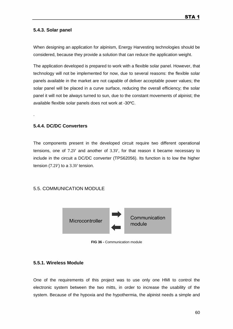
STA 1
60
5.4.3. Solar panel
When designing an application for alpinism, Energy Harvesting technologies should be
considered, because they provide a solution that can reduce the application weight.
The application developed is prepared to work with a flexible solar panel. However, that
technology will not be implemented for now, due to several reasons: the flexible solar
panels available in the market are not capable of deliver acceptable power values; the
solar panel will be placed in a curve surface, reducing the overall efficiency; the solar
panel it will not be always turned to sun, due to the constant movements of alpinist; the
available flexible solar panels does not work at -30ºC.
.
5.4.4. DC/DC Converters
The components present in the developed circuit require two different operational
tensions, one of and another of , for that reason it became necessary to
include in the circuit a DC/DC converter (TPS62056). Its function is to low the higher
tension ( ) to a tension.
5.5. COMMUNICATION MODULE
FIG 36 - Communication module
5.5.1. Wireless Module
One of the requirements of this project was to use only one HMI to control the
electronic system between the two mitts, in order to increase the usability of the
system. Because of the hypoxia and the hypothermia, the alpinist needs a simple and
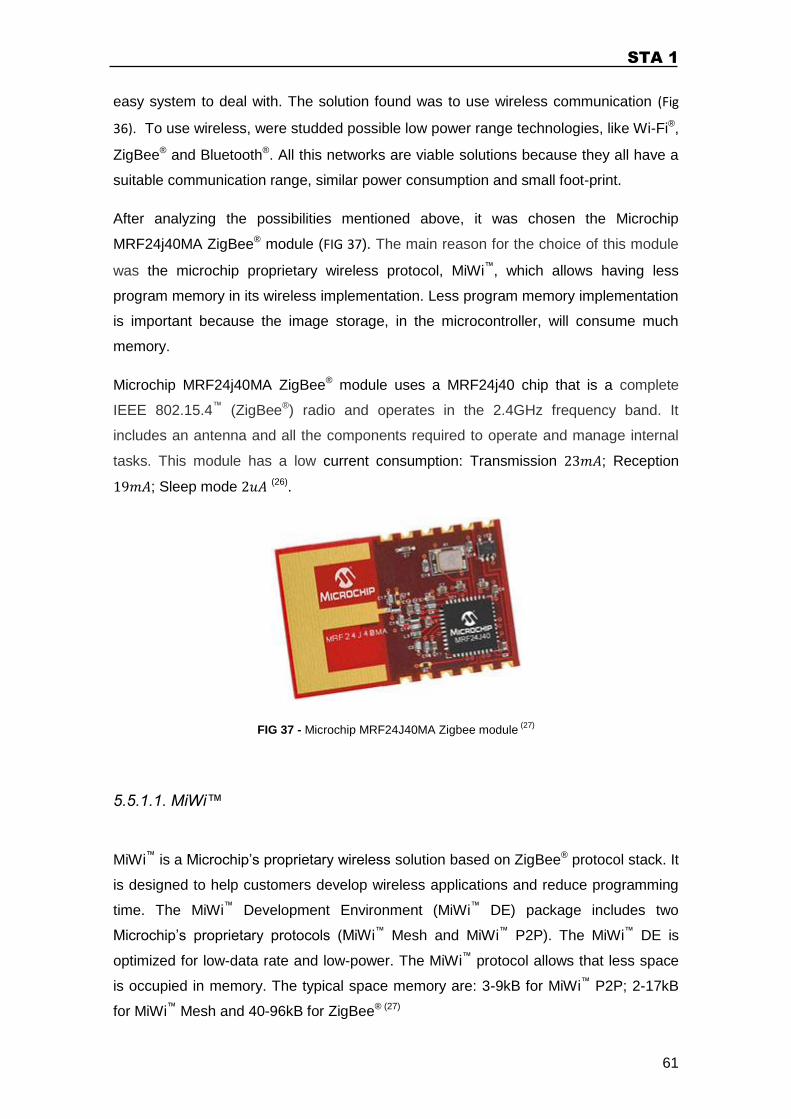
STA 1
61
easy system to deal with. The solution found was to use wireless communication (Fig
36). To use wireless, were studded possible low power range technologies, like Wi-Fi®,
ZigBee® and Bluetooth®. All this networks are viable solutions because they all have a
suitable communication range, similar power consumption and small foot-print.
After analyzing the possibilities mentioned above, it was chosen the Microchip
MRF24j40MA ZigBee® module (FIG 37). The main reason for the choice of this module
was the microchip proprietary wireless protocol, MiWi™, which allows having less
program memory in its wireless implementation. Less program memory implementation
is important because the image storage, in the microcontroller, will consume much
memory.
Microchip MRF24j40MA ZigBee® module uses a MRF24j40 chip that is a complete
IEEE 802.15.4™ (ZigBee®) radio and operates in the 2.4GHz frequency band. It
includes an antenna and all the components required to operate and manage internal
tasks. This module has a low current consumption: Transmission ; Reception
; Sleep mode (26).
FIG 37 - Microchip MRF24J40MA Zigbee module (27)
5.5.1.1. MiWi™
MiWi™ is a Microchip’s proprietary wireless solution based on ZigBee® protocol stack. It
is designed to help customers develop wireless applications and reduce programming
time. The MiWi™ Development Environment (MiWi™ DE) package includes two
Microchip’s proprietary protocols (MiWi™ Mesh and MiWi™ P2P). The MiWi™ DE is
optimized for low-data rate and low-power. The MiWi™ protocol allows that less space
is occupied in memory. The typical space memory are: 3-9kB for MiWi™ P2P; 2-17kB
for MiWi™ Mesh and 40-96kB for ZigBee® (27)
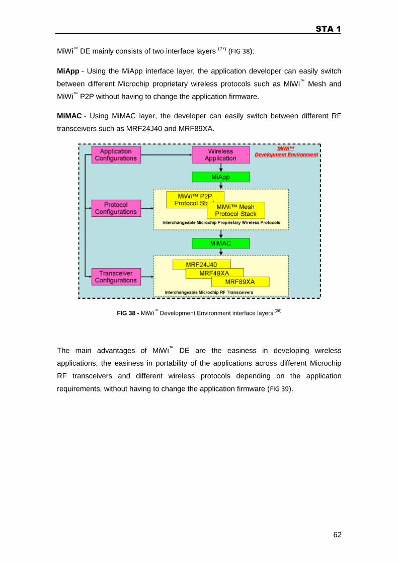
STA 1
62
MiWi™ DE mainly consists of two interface layers (27) (FIG 38):
MiApp - Using the MiApp interface layer, the application developer can easily switch
between different Microchip proprietary wireless protocols such as MiWi™ Mesh and
MiWi™ P2P without having to change the application firmware.
MiMAC - Using MiMAC layer, the developer can easily switch between different RF
transceivers such as MRF24J40 and MRF89XA.
FIG 38 - MiWi™
Development Environment interface layers (26)
The main advantages of MiWi™ DE are the easiness in developing wireless
applications, the easiness in portability of the applications across different Microchip
RF transceivers and different wireless protocols depending on the application
requirements, without having to change the application firmware (FIG 39).
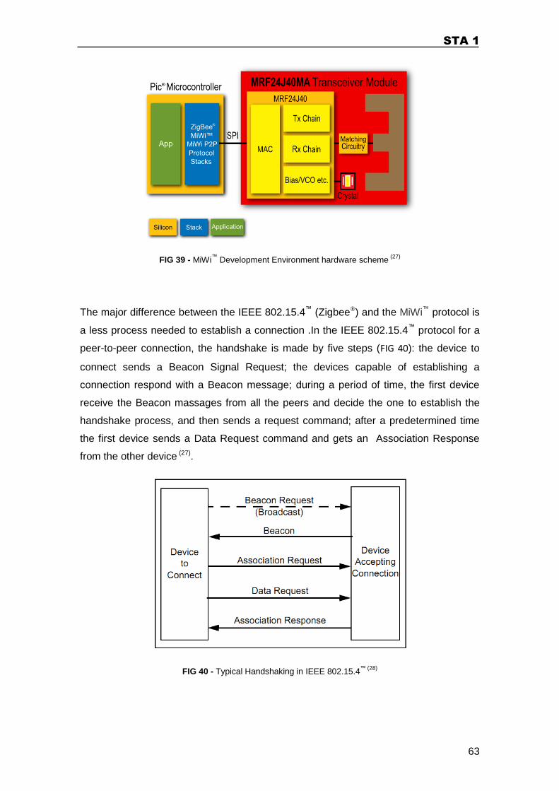
STA 1
63
FIG 39 - MiWi™
Development Environment hardware scheme (27)
The major difference between the IEEE 802.15.4™ (Zigbee®) and the MiWi™ protocol is
a less process needed to establish a connection .In the IEEE 802.15.4™ protocol for a
peer-to-peer connection, the handshake is made by five steps (FIG 40): the device to
connect sends a Beacon Signal Request; the devices capable of establishing a
connection respond with a Beacon message; during a period of time, the first device
receive the Beacon massages from all the peers and decide the one to establish the
handshake process, and then sends a request command; after a predetermined time
the first device sends a Data Request command and gets an Association Response
from the other device (27).
FIG 40 - Typical Handshaking in IEEE 802.15.4™ (28)
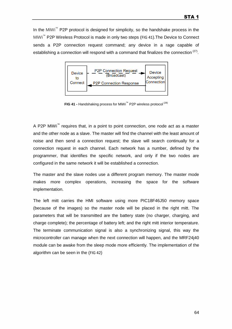
STA 1
64
In the MiWi™ P2P protocol is designed for simplicity, so the handshake process in the
MiWi™ P2P Wireless Protocol is made in only two steps (FIG 41).The Device to Connect
sends a P2P connection request command; any device in a rage capable of
establishing a connection will respond with a command that finalizes the connection (27).
FIG 41 - Handshaking process for MiWi™
P2P wireless protocol (28)
A P2P MiWi™ requires that, in a point to point connection, one node act as a master
and the other node as a slave. The master will find the channel with the least amount of
noise and then send a connection request; the slave will search continually for a
connection request in each channel. Each network has a number, defined by the
programmer, that identifies the specific network, and only if the two nodes are
configured in the same network it will be established a connection.
The master and the slave nodes use a different program memory. The master mode
makes more complex operations, increasing the space for the software
implementation.
The left mitt carries the HMI software using more PIC18F46J50 memory space
(because of the images) so the master node will be placed in the right mitt. The
parameters that will be transmitted are the battery state (no charger, charging, and
charge complete); the percentage of battery left; and the right mitt interior temperature.
The terminate communication signal is also a synchronizing signal, this way the
microcontroller can manage when the next connection will happen, and the MRF24j40
module can be awake from the sleep mode more efficiently. The implementation of the
algorithm can be seen in the (FIG 42)
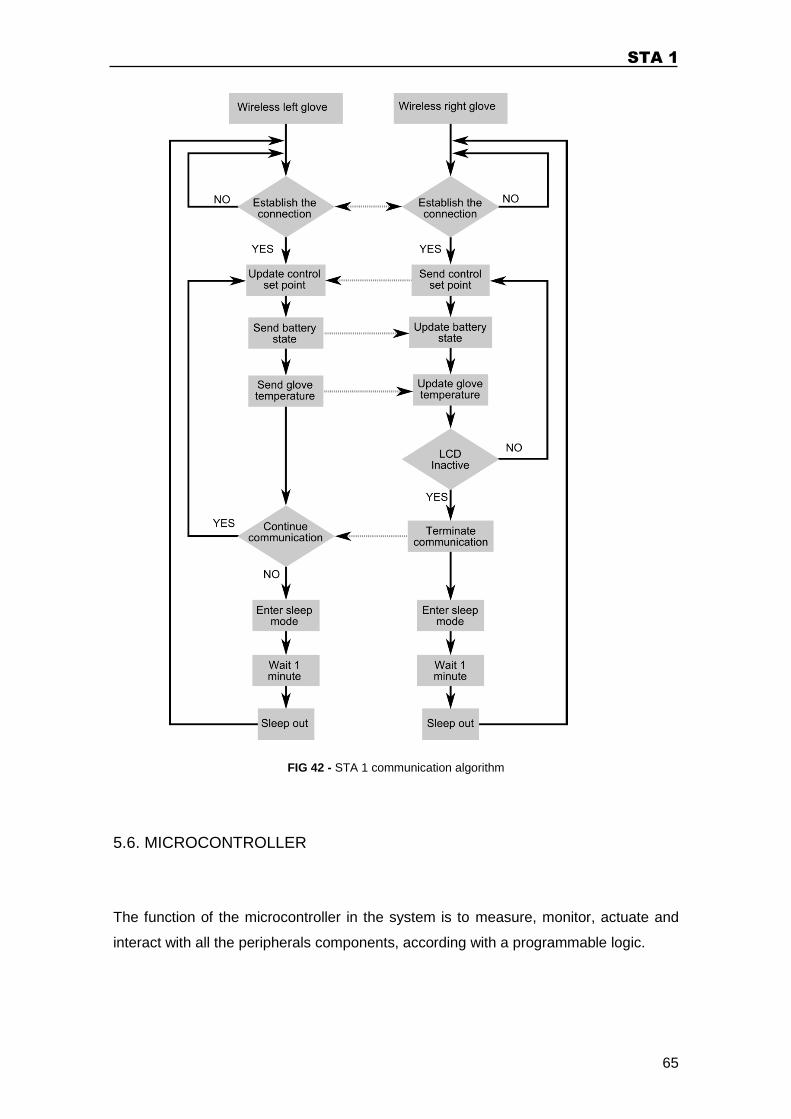
STA 1
65
FIG 42 - STA 1 communication algorithm
5.6. MICROCONTROLLER
The function of the microcontroller in the system is to measure, monitor, actuate and
interact with all the peripherals components, according with a programmable logic.
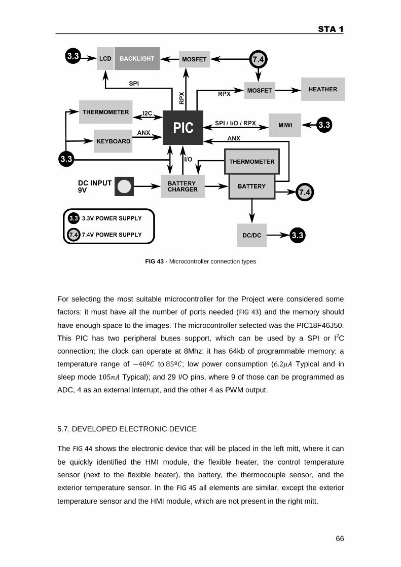
STA 1
66
FIG 43 - Microcontroller connection types
For selecting the most suitable microcontroller for the Project were considered some
factors: it must have all the number of ports needed (FIG 43) and the memory should
have enough space to the images. The microcontroller selected was the PIC18F46J50.
This PIC has two peripheral buses support, which can be used by a SPI or I2C
connection; the clock can operate at 8Mhz; it has 64kb of programmable memory; a
temperature range of to ; low power consumption ( Typical and in
sleep mode Typical); and 29 I/O pins, where 9 of those can be programmed as
ADC, 4 as an external interrupt, and the other 4 as PWM output.
5.7. DEVELOPED ELECTRONIC DEVICE
The FIG 44 shows the electronic device that will be placed in the left mitt, where it can
be quickly identified the HMI module, the flexible heater, the control temperature
sensor (next to the flexible heater), the battery, the thermocouple sensor, and the
exterior temperature sensor. In the FIG 45 all elements are similar, except the exterior
temperature sensor and the HMI module, which are not present in the right mitt.
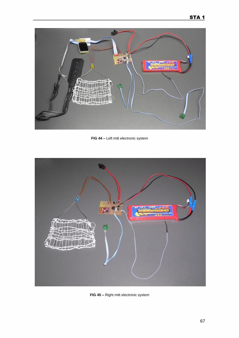
STA 1
67
FIG 44 – Left mitt electronic system
FIG 45 – Right mitt electronic system
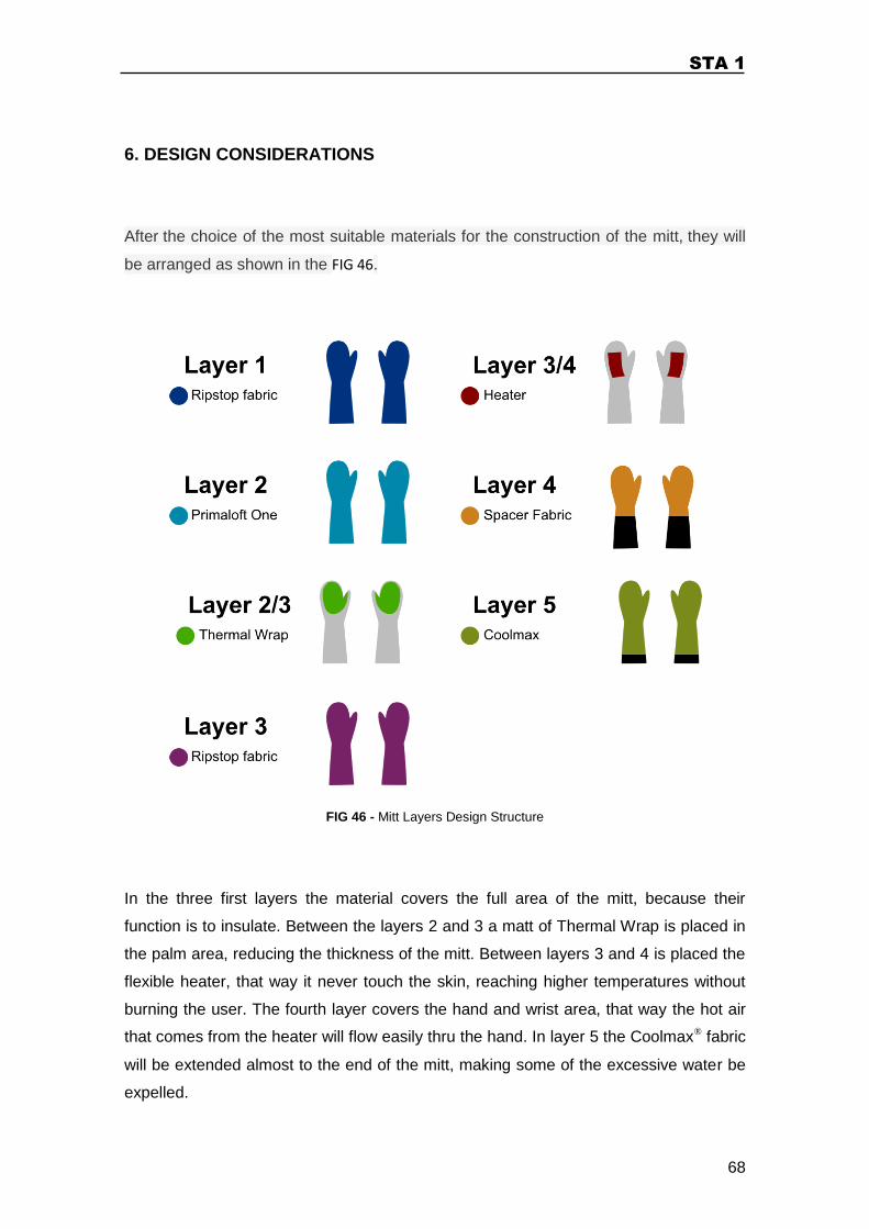
STA 1
68
6. DESIGN CONSIDERATIONS
After the choice of the most suitable materials for the construction of the mitt, they will
be arranged as shown in the FIG 46.
FIG 46 - Mitt Layers Design Structure
In the three first layers the material covers the full area of the mitt, because their
function is to insulate. Between the layers 2 and 3 a matt of Thermal Wrap is placed in
the palm area, reducing the thickness of the mitt. Between layers 3 and 4 is placed the
flexible heater, that way it never touch the skin, reaching higher temperatures without
burning the user. The fourth layer covers the hand and wrist area, that way the hot air
that comes from the heater will flow easily thru the hand. In layer 5 the Coolmax® fabric
will be extended almost to the end of the mitt, making some of the excessive water be
expelled.
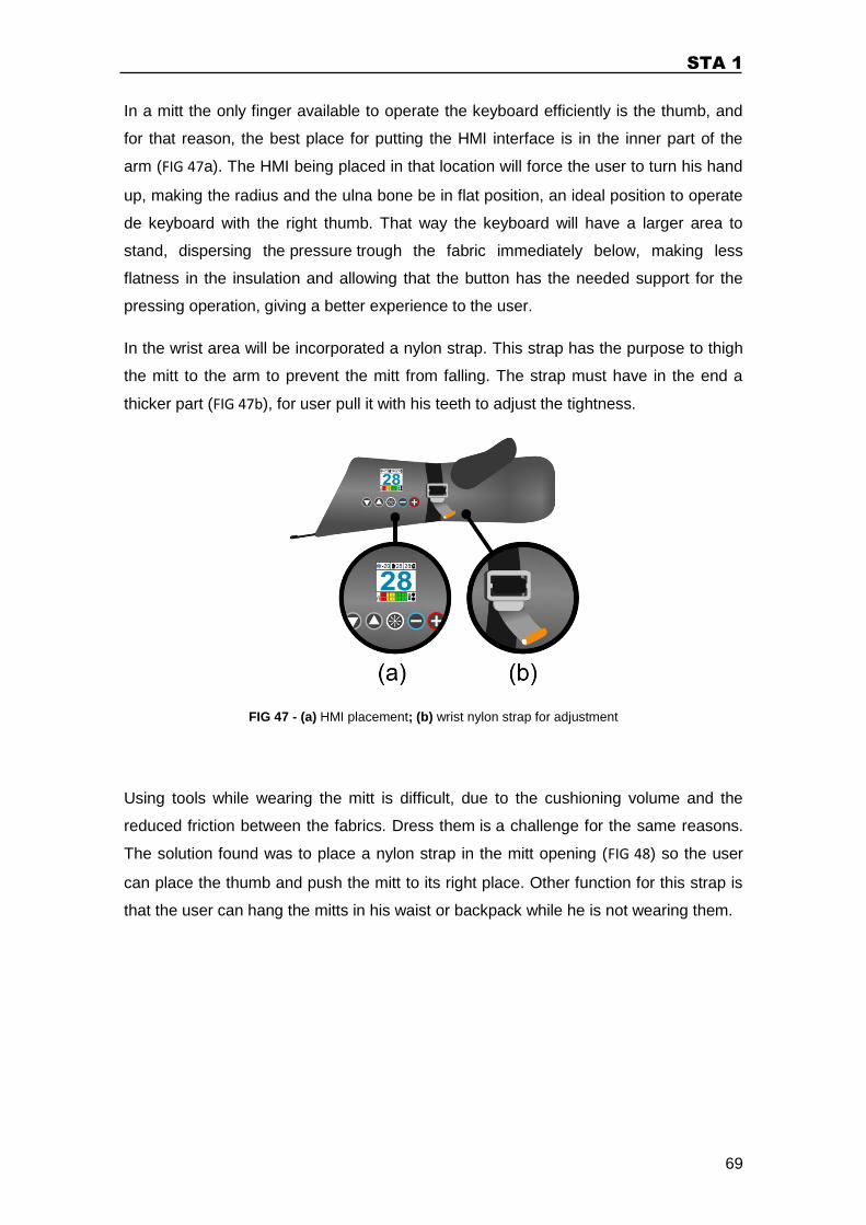
STA 1
69
In a mitt the only finger available to operate the keyboard efficiently is the thumb, and
for that reason, the best place for putting the HMI interface is in the inner part of the
arm (FIG 47a). The HMI being placed in that location will force the user to turn his hand
up, making the radius and the ulna bone be in flat position, an ideal position to operate
de keyboard with the right thumb. That way the keyboard will have a larger area to
stand, dispersing the pressure trough the fabric immediately below, making less
flatness in the insulation and allowing that the button has the needed support for the
pressing operation, giving a better experience to the user.
In the wrist area will be incorporated a nylon strap. This strap has the purpose to thigh
the mitt to the arm to prevent the mitt from falling. The strap must have in the end a
thicker part (FIG 47b), for user pull it with his teeth to adjust the tightness.
FIG 47 - (a) HMI placement; (b) wrist nylon strap for adjustment
Using tools while wearing the mitt is difficult, due to the cushioning volume and the
reduced friction between the fabrics. Dress them is a challenge for the same reasons.
The solution found was to place a nylon strap in the mitt opening (FIG 48) so the user
can place the thumb and push the mitt to its right place. Other function for this strap is
that the user can hang the mitts in his waist or backpack while he is not wearing them.
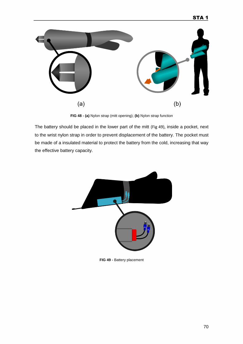
STA 1
70
FIG 48 - (a) Nylon strap (mitt opening); (b) Nylon strap function
The battery should be placed in the lower part of the mitt (Fig 49), inside a pocket, next
to the wrist nylon strap in order to prevent displacement of the battery. The pocket must
be made of a insulated material to protect the battery from the cold, increasing that way
the effective battery capacity.
FIG 49 - Battery placement
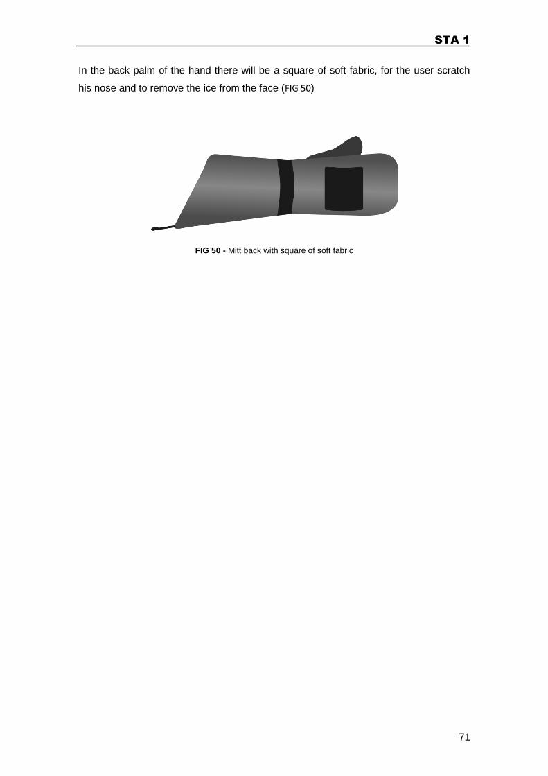
STA 1
71
In the back palm of the hand there will be a square of soft fabric, for the user scratch
his nose and to remove the ice from the face (FIG 50)
FIG 50 - Mitt back with square of soft fabric
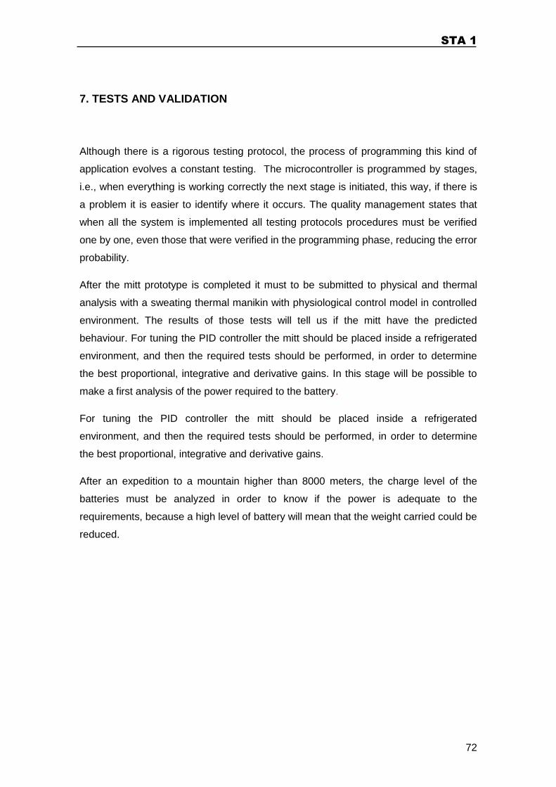
STA 1
72
7. TESTS AND VALIDATION
Although there is a rigorous testing protocol, the process of programming this kind of
application evolves a constant testing. The microcontroller is programmed by stages,
i.e., when everything is working correctly the next stage is initiated, this way, if there is
a problem it is easier to identify where it occurs. The quality management states that
when all the system is implemented all testing protocols procedures must be verified
one by one, even those that were verified in the programming phase, reducing the error
probability.
After the mitt prototype is completed it must to be submitted to physical and thermal
analysis with a sweating thermal manikin with physiological control model in controlled
environment. The results of those tests will tell us if the mitt have the predicted
behaviour. For tuning the PID controller the mitt should be placed inside a refrigerated
environment, and then the required tests should be performed, in order to determine
the best proportional, integrative and derivative gains. In this stage will be possible to
make a first analysis of the power required to the battery.
For tuning the PID controller the mitt should be placed inside a refrigerated
environment, and then the required tests should be performed, in order to determine
the best proportional, integrative and derivative gains.
After an expedition to a mountain higher than 8000 meters, the charge level of the
batteries must be analyzed in order to know if the power is adequate to the
requirements, because a high level of battery will mean that the weight carried could be
reduced.
STA 1
73
8. CONCLUSION
Alpinism garment is not foreseen for mass market, because the number of practitioners
is low, comparing to other sports. Due to that fact the scientific development of specific
equipment for alpinism is reduced. In general the Alpinism equipment is improvised,
adapted solutions from other activities that do not fulfil the real needs.
With this work was possible to conclude that is not easy to predict the real functioning
of the mitt application. The unpredictability of the human body behaviour in a harsh
environment, such as the high-mountain environment, makes it very difficult to
establish an exact value of all parameters.
The mitt solution (apparel + electronic control system) was designed based on
scientific data. Theoretically, the result will work properly in a Alpinism expedition, but
in practice there is no enough information, because the validation tests were not
performed yet.
STA 1
74
9. FUTURE WORK
Technology is always evolving and some of the best solutions available today have not
reached their entire potential or are yet too costly.
In this projects were identified some points that in the future can be changed or added,
in order to improved the overall efficiency of the system.
With the increase of investigation related with batteries and solar panel technologies, in
the future, these elements can be changed or implemented in order to reduce the
overall weight.
Other possible modification is the change of the LCD display to an electronic paper
display. The electronic paper display spends a very low amount of energy, allowing the
information be always available on screen and they can be easily read under intense
sunlight. In this moment is not possible to implement this kind of display, for 3 reasons:
they are not easy to acquire; the price is much higher than the regular LCD; and they
do not work in the required temperature range.
The usage of a flexible far infrared heater (FIR) must be considered in a next version of
STA. This type of heaters presents very interesting characteristics: they distribute the
heat in a more efficient way and if suffers damage it continues operating, because its
structure is not a continuous wire like the used in STA 1.
It would be interesting to incorporate a memory to store data of all the temperature
values, as wells as the set point values and the battery state, in order to study the
system behaviour and optimize it.
STA 1
75
ACRONYMS
– Plane surface area
ATP - adenosine triphosphate
Bpm – Beats per minute
Clo – Clothing insulation value
– Derivative controller
E – Error
– Heat loss due to vapour diffusion through the skin
– Heat loss respiration latent heat loss
– Heat loss due to evaporation of regulatory sweating from the skin
HMI – Human machine interface
– Convection heat transfer coefficient
– Radiation heat transfer coefficient
– Integrative controller
– Thermal conduction coefficient
– Derivative gain
– Integral gain
– Proportional gain
– Sensible (dry) heat loss, respiration
– PID controller output
PID – Proportional, integrator and derivative controller
PV – Process output value
– Proportional controller
STA 1
76
– Saturation vapour pressure
– Partial vapour pressure
– vapour pressure
– Rate of heat transfer
– Conduction heat transfer
– Convection heat transfer
– Radiation heat transfer
– Relative humidity
SP – Set point
STA1 – Space Technologies on Alpinism Phase1
– Dew point
– Relative humidity
– Absorptivity
– Emissivity
– Stefan-Boltzmann constant
– Efficiency
STA 1
77
GLOSSARY
A
Alpinism – sport or activity of climbing of the Alps or any equally high mountain
ranges.
Amino acid – a simple organic compound, containing carboxyl (−COOH) and an
amino (−NH 2) group.
Anabolism - the synthesis of complex molecules in living organisms from simpler ones
together with the storage of energy; constructive metabolism.
Anemia - a condition marked by a deficiency of red blood cells or of hemoglobin in the
blood, resulting in pallor and weariness.
Apathy - lack of interest, enthusiasm, or concern.
Arrhythmia – one or more irregularities in the force or rhythm of the heartbeat.
Arterial blood pressure - blood pressure in the arterial walls during the cardiac
contraction.
ATP - adenosine triphosphate; a compound consisting of an adenosine molecule
bonded to three phosphate groups, present in all living tissue. The breakage of one
phosphate linkage (to form adenosine diphosphate, ADP) provides energy for
physiological processes such as muscular contraction.
B
Basal metabolism - rate at which the body uses energy while at rest to keep vital
functions going, such as breathing and keeping warm.
Bradycardia – abnormally low cardiac frequency (less than 60 bpm).
STA 1
78
C
Cardiac Frequency - Number of times that heart contracts in a minute.
Cardiac output - is the volume of blood being pumped by the heart, in particular by a
left or right ventricle in the time interval of one minute.
Catabolism - the breakdown of complex molecules in living organisms to form simpler
ones, together with the release of energy; destructive metabolism.
Cellular metabolism – also known as cellular respiration; set of
the metabolic reactions and processes that take place in the cells of organisms to
convert biochemical energy from nutrients into adenosine triphosphate (ATP), and then
release waste products.
Coma - state of deep unconsciousness that lasts for a prolonged or indefinite period,
caused especially by severe injury or illness.
Condensation - process by which a gas is converted from vapour form to its liquid
form.
Conduction – interaction between particles with different energy, where the more
energetic transfers energy to the less energetic.
Convection - heat transfer from a solid surface to a liquid or gas, in motion.
Core temperature (human body) - temperature of the deep structures of the human
body, in comparison to the peripheral tissues temperature.
Cyanosis - a bluish discoloration of the skin resulting from poor circulation or
inadequate oxygenation of the blood.
D
Dehydration – excessive loss of body water.
Delirium - an acutely disturbed state of mind that occurs in fever, intoxication, and
other disorders and is characterized by restlessness, illusions, and incoherence of
thought and speech.
Dyspnea – a difficult or labored breathing.
STA 1
79
E
Erythropoietin - a hormone secreted by the kidneys that increases the rate of
production of red blood cells in response to falling levels of oxygen in the tissues
Euphoria - a feeling or state of intense excitement and happiness.
Evaporation - process by which water is converted from its liquid form to its vapor
form.
F
Fatty acids - a carboxylic acid consisting of a hydrocarbon chain and a terminal
carboxyl group, esp. any of those occurring as esters in fats and oils.
Frostbite - injury to body tissues caused by exposure to extreme cold, typically
affecting the nose, fingers, or toes and sometimes resulting in gangrene.
Frostnip - the first stage of frostbite.
G
Gangrene – a localized death and decomposition of body tissue, resulting from either
obstructed circulation or bacterial infection.
H
Hematologic components – the elements that compose the blood: leukocytes, red
blood cells and platelets.
Hemoglobin - a red protein responsible for transporting oxygen in the blood of
vertebrates. Its molecule comprises four subunits, each containing an iron atom bound
to a heme group.
High-Mountain – mountain above 2500 meters of altitude.
STA 1
80
Homeostasis - the tendency toward a relatively stable equilibrium between
interdependent elements, especially as maintained by physiological processes.
Hypertension – abnormally high blood pressure, when the systolic pressure, of a
rested person, is , and diastolic pressure is .
Hypobaric - relating to conditions of low air pressure and low oxygen content, such as
atmospheric conditions at high altitudes, or in special chambers used to establish low-
pressure conditions.
Hypoglycemia – deficient amount of glucose in the bloodstream (Adult glycemia
).
Hypothalamus – a region of the forebrain below the thalamus that coordinates both
the autonomic nervous system and the activity of the pituitary, controlling body
temperature, thirst, hunger, and other homeostatic systems, and involved in sleep and
emotional activity.
Hypothermia - condition of having an abnormally low body temperature, typically one
that is dangerously low.
Hypoxia – presence low amount of oxygen in the tissues.
L
Lethargy – condition of lack of energy and enthusiasm, which cannot be overcome by
the will.
Lipids - any of a class of organic compounds that are fatty acids or their derivatives
and are insoluble in water but soluble in organic solvents. They include many natural
oils, waxes, and steroids.
M
Metabolism - chemical processes that occur within a living organism in order to
maintain life.
Metabolite - a substance formed in or necessary for metabolism.
STA 1
81
Monosaccharide - any of the class of sugars (e.g., glucose) that cannot be hydrolyzed
to give a simpler sugar.
Mountaineering - sport or activity of climbing mountains.
N
Nausea - a feeling of sickness with an inclination to vomit.
Nucleic acid - a complex organic substance present in living cells, especially in DNA
or RNA, whose molecules consist of many nucleotides linked in a long chain.
Nutrients - a substance that provides nourishment essential for growth and the
maintenance of life.
O
Osmosis - process by which molecules of a solvent tend to pass through a
semipermeable membrane from a less concentrated solution into a more concentrated
one, equaling the concentration on each side of the membrane.
Oxygenation – process of supplying, treat, charge, or enrich with oxygen.
P
Partial pressure of inspired oxygen (PIO2) - pressure of O2 calculated at sea level.
At sea level, the atmospheric pressure is 760 mm Hg. This equals the force exerted by
a column of mercury 760 mm high. Since the atmosphere is 21% oxygen, the partial
pressure of O2 is 0.21 x 760 = 160 mm Hg.
Polysaccharide - a carbohydrate (e.g., starch, cellulose, or glycogen) whose
molecules consist of a number of sugar molecules bonded together.
Pulmonary alveolus - small polyhedral outpunchings along the walls of the alveolar
sacs, alveolar ducts and terminal bronchioles through the walls of which gas
exchange between alveolar air and pulmonary capillary blood takes place.

STA 1
82
R
Radiation - energy emitted by a body in the form of electromagnetic waves, at a
determined temperature.
Raynaud’s Syndrome – Spasmodic contraction of the peripheral blood vessels,
mainly fingers, showed by the cold and pail hands, prone to ulcers and
gangrene by poor circulation.
Relative humidity - the amount of water vapor present in air expressed as a
percentage of the amount needed for saturation at the same temperature.
S
Seizure - Uncontrolled electrical activity in the brain, which may produce a physical
convulsion, minor physical signs, thought disturbances, or a combination of symptoms.
Stupor – a state of near-unconsciousness or insensibility.
Synthesis – the production of chemical compounds by reaction from simpler materials.
T
Tachycardia – abnormally high cardiac frequency (more than 100 bpm).
Tachypnea - abnormally rapid superficial breathing; reflex response to the stimulation
by the vagus nerve in the pulmonary vessels.
Terminal burrowing behavior - autonomous process of the brain stem, which triggers
a behavior pattern observed in the last stages of lethal hypothermia, producing a
primitive and burrowing-like behaviour of protection, as seen in hibernating animals,
where people tend to hide themselves under a bed, behind a wardrobe, in a shelf etc.
Thin air – air with low amounts of oxygen saturation.
Throbbing – a feeling of pain in a series of regular beats.
STA 1
83
V
Vapor pressure – the pressure of a vapor in contact with a liquid or solid form.
Vasoconstriction - constriction of blood vessels, which increases blood pressure.
Ventricular fibrillation – sudden and rapid contractions of the hearth ventricles,
leading to a circulatory arrest, which quickly becomes lethal.
Visual Impairment - low vision is a severe reduction in vision that cannot be corrected
with standard glasses or contact lenses and reduces a person's ability to function at
certain or all tasks.
STA 1
84
REFERENCES
1. ASHCROFT, Frances. Desafiar os Limites. [trans.] Sofia Gomes. 1st Edition.
Lisbon : Editorial Bizâncio, 2006. p. 368. ISBN-13: 978-972-53-0313-9.
2. CHRYSTAL, Chad S. Hypothermia. emedicinehealth. [Online] August 10, 2005.
[Cited: January 06, 2010.] [Available]
http://www.emedicinehealth.com/hypothermia/article_em.htm.
3. KEELER, Sharon. Cold Weather Increases Risk Of Dehydration. UNH Media
Relations. [Online] January 28, 2005. [Cited: May 16, 2010.] [Available]
http://www.unh.edu/news/news_releases/2005/january/sk_050128cold.html.
4. WEDRO, Benjamin C. Dehydration. medicinenet.com. [Online] July 13, 2011.
[Cited: July 20, 2011.] [Available] http://www.medicinenet.com/dehydration/article.htm.
5. SEELEY, Rod R., STEPHENS, Trent D. and TATE, Philip. Anatomia & Fisiologia.
[trans.] Maria Cândida Durão, Maria Leonor Braga Abecasis Maria Teresa Leal. s.l. :
Lusociência, 2003. ISBN: 972-8930-07-0.
6. Conselho Internacional de Enfermeiros (ICN). Classificação Internacional para a
Prática de Enfermagem CIPE/ICNP. Ordem dos Enfermeiros Portugueses. [Online]
2010 йил. [Cited: 2010 йил 16-May.]
http://www.ordemenfermeiros.pt/browserCIPE/BrowserCIPE.aspx.
7. GUYTON, A. C. Fisiologia Humana. 6th Edition. Rio de Janeiro : Guanabara
Koogan, 1988. p. 576. ISBN: 978-852-77-1412-9.
8. The American Heritage® Dictionary of the English Language. Hypobaric. The
Free Dictionary. [Online] 2009. [Cited: February 06, 2010.] [Available]
http://www.thefreedictionary.com/hypobaric.
9. MAGALHÃES, J., et al. O desafio da altitude. Uma perspectiva fisiológica. Revista
Portuguesa de Ciências do Desporto. nº4, 2002, Vol. 2, Sport Science.
10. STÖPPLER, Melissa Conrad. Frostbite. emedicinehealth. [Online] January 28,
2010. [Cited: January 06, 2010.] [Available]
http://www.emedicinehealth.com/frostbite/page11_em.htm#Authors and Editors.
STA 1
85
11. DOERR, Steven. Frostbite and Cold Weather-Related Injuries. medicinenet.com.
[Online] April 18, 2011. [Cited: May 16, 2011.] [Available]
http://www.medicinenet.com/frostbite/article.htm.
12. British Occupational Hygiene Society. The Thermal Environment. [Online] 1996.
[Available] http://www.bohs.org/uploadedFiles/Library/Publications/TG12(1).pdf. ISBN:
0-948237-29-5.
13. STARNER, Thad and MAGUIRE, Yeal. A Heat Dissipation Toturial for Wearable
Computers. [Online] 1998. [Available]
http://www.cc.gatech.edu/~thad/p/032_30_power&heat/heat_diddipation_ISWC98.pdf.
ISSN: 0-8186-9074-7/98.
14. PARISH, Owen O. and PUTNAM, Terrill W. Equations for the determination of
humidity from dewpoint and psychrometric data. National Aeronautics and Space
Administration. [Online] January 1977. [Cited: June 13, 2011.] [Available]
http://www.nasa.gov/centers/dryden/pdf/87878main_H-937.pdf.
15. NAVE, Carl Rod. Relative Humidity. Hyperphysics. [Online] 1997. [Cited: July 20,
2011.] [Available] http://hyperphysics.phy-astr.gsu.edu/hbase/hframe.html.
16. Parish, Owen O. and Putnam, Terrill W. Equations for the determination of
humidity from dewpoint and psychrometric data. NASA Technical Note D-8401.
[Document]. Washington D. C. : s.n., January 1977.
http://www.nasa.gov/centers/dryden/pdf/87878main_H-937.pdf.
17. ALDUCHOV, Oleg A. e ESKRIDGE, Robert E. Improved Magnus Form
Aproximation of Saturation Vapor Pressure. Journal of Applied Meteorology. April de
1996, pp. 601-609.
18. ÇENGEL, Yanus A. Heat Transfer: A Practical Approach. 2nd Edition. New York :
McGraw-Hill Companies, 2003. p. 932. ISBN: 0-07-115150-8.
19. British Broadcasting Corporation (BBC). BBC Four Documentaries: The Ice
King. [Video] s.l. : BBC, August 2008. [Available]
http://www.bbc.co.uk/bbcfour/documentaries/features/voyages-discovery.shtml.
20. Changshu Diwang Knitting Co.,Ltd. Spacer Fabric. ecplaza.net. [Online]
[Citação: 4 de February de 2010.] [Available] http://dwmesh.en.ecplaza.net/1.asp.
STA 1
86
21. FANGER, P.O. Calculation of the thermal comfort:Introduction of a basic comfort
equation. ASHRAE Transactions. 1967, Vols. 73, Part II, Nº 2051, pp. III,4.1.-III, 4.20.
22. SILVA, Manuel Carlos Gameiro. Aplicações Computacionais para Avaliação do
Comforto Térmico. ADAI - Departamento de Engenharia Mecânica da Faculdade de
Ciencias e Tecnologia, Universidade de Coimbra - Polo II. Coimbra : DEM. p. 19.
[Available] https://woc.uc.pt/dem/getFile.do?tipo=2&id=7124.
23. AULICIEMS, Andris and SZOKOLAY, Steven V. Thermal Comfort. Department of
Architecture, PLEA:Passive and Low Energy Architecture International in Association
with the University of Queensland . Queensland : s.n., 2007. p. 68. [Available]
www.arct.cam.ac.uk/PLEA/Download.aspx?p=9&rcid=10&ix=6. ISBN 0 86776 729 4.
24. LIDWELL, William, HOLDEN, Kritina and BUTLER, Jill. Universal Principles of
Design. 1st Edition. massachusets, U.S.A. : Rockport Publishers, 2010. p. 272. ISBN:
1-59253-007-9.
25. Texas Instruments. Synchronous switch mode, li-ion and li-polymer charge-
management IC with integrated power FETs ( bqSWITCHER™). Texas Instruments.
[Online] March 2010. [Cited: 13 April 2011.] [Available]
http://www.ti.com/lit/ds/symlink/bq24113a.pdf.
26. Microchip. MiWI Development Environment. Microchip. [Online] 1998-2011. [Cited:
July 20, 2011.] [Available]
http://www.microchip.com/stellent/idcplg?IdcService=SS_GET_PAGE&nodeId=2664&p
aram=en520414&redirects=miwi.
27. anglia M2M. MiWi™ and MiWi P2P (peer-to-peer). angliaM2M. [Online] 1995-
2011. [Cited: July 20, 2011.] http://www.anglia-m2m.com/Point_to_point.asp.
[Available] http://www.anglia-m2m.com/Point_to_point.asp.
28. YAN, Yifeng. Microchip MiWi™ P2P Wireless Protocol. AN1204. U.S.A. :
Microchip Technology Incorporated, 2010. [Available]
http://ww1.microchip.com/downloads/en/AppNotes/01204B.pdf. ISBN: 978-1-60932-
347-9.
29. CHATTERJEE, G.N., et al. Clothing for Antarctica. Department of Ocean
Development, National Center for Antarctic & Ocean Research. Kanpur : Technical
Publication, 1988. pp. 421-432, Scientific Report. [Available]
http://dspace.ncaor.org:8080/dspace/bitstream/123456789/291/3/article31.pdf.

STA 1
87
30. WELLER, Barbara F. Dicionário de Bolso para Enfermeiros. [trans.] Sofia Ribeiro.
23rd Edition. Loures : Lusociência - Edições Técnicas e Científicas, Lda., 2004. ISBN:
972-8383-72-X.
31. GUIMENEZ, Julio, FIOLHAIS, Carlos e FIOLHAIS, Manuel. Fundamentos de
Termodinâmica do Equlíbrio. 1st Edition. Lisboa : Fundação Calouste Gulbenkian,
1998. p. 481. ISBN: 972-31-0796-1.
32. REGER, Daniel, GOODE, Scott e MERCER, Edward. Química: Princípios e
Aplicações. [trad.] António Pires Matos, et al. Lisboa : Fundação Calouste Gulbenkian,
1997. p. 1300. ISBN: 972-31-0773-2.
33. American Sociaty of Heating, Refrigerating and Air-condicioning Engineers,
INC. Thermal Environmental Conditions for Human Occupancy. 3rd Public Review
ASHRAE® Standard 55P. Atlanta : ASHRAE®, 2003. [Available] www.krueger-
hvac.com/lit/pdf/therm_comf.pdf.
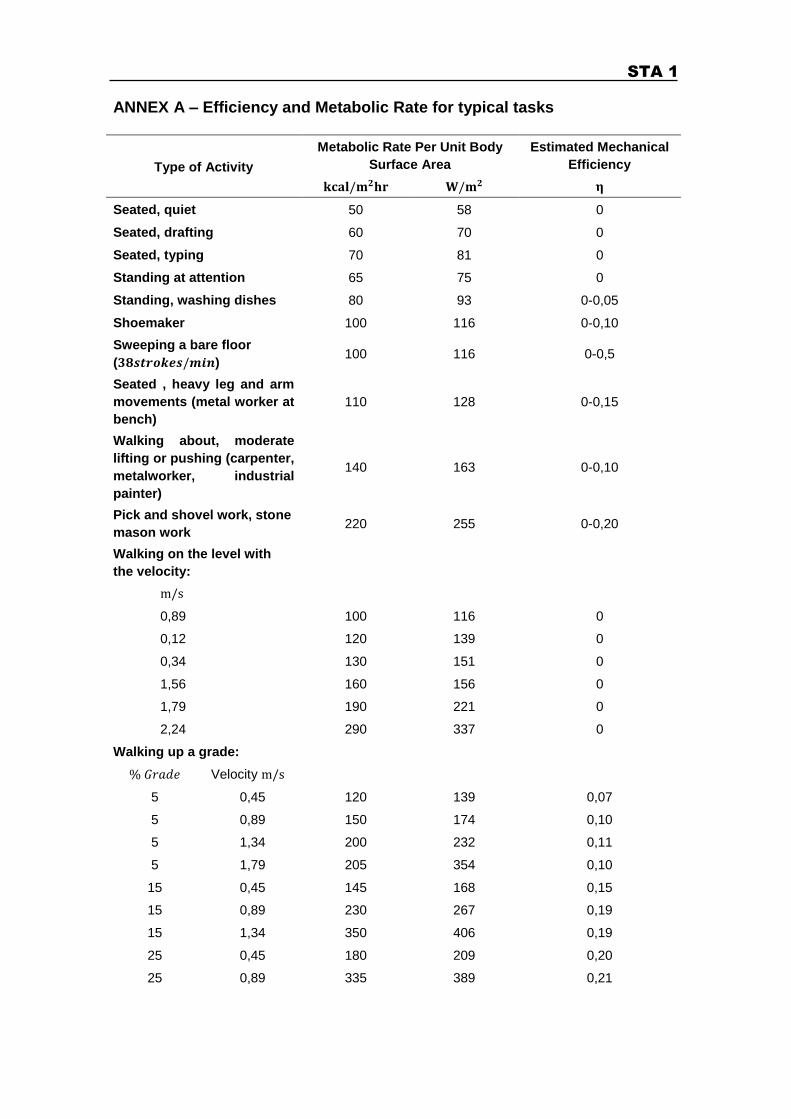
STA 1
ANNEX A – Efficiency and Metabolic Rate for typical tasks
Type of Activity
Metabolic Rate Per Unit Body
Surface Area
Estimated Mechanical
Efficiency
Seated, quiet 50 58 0
Seated, drafting 60 70 0
Seated, typing 70 81 0
Standing at attention 65 75 0
Standing, washing dishes 80 93 0-0,05
Shoemaker 100 116 0-0,10
Sweeping a bare floor
( ) 100 116 0-0,5
Seated , heavy leg and arm
movements (metal worker at
bench)
110 128 0-0,15
Walking about, moderate
lifting or pushing (carpenter,
metalworker, industrial
painter)
140 163 0-0,10
Pick and shovel work, stone
mason work 220 255 0-0,20
Walking on the level with
the velocity:
0,89 100 116 0
0,12 120 139 0
0,34 130 151 0
1,56 160 156 0
1,79 190 221 0
2,24 290 337 0
Walking up a grade:
Velocity
5 0,45 120 139 0,07
5 0,89 150 174 0,10
5 1,34 200 232 0,11
5 1,79 205 354 0,10
15 0,45 145 168 0,15
15 0,89 230 267 0,19
15 1,34 350 406 0,19
25 0,45 180 209 0,20
25 0,89 335 389 0,21


![Monografie, Bucegi Turism-Alpinism - Em. Cristea [1961]](https://img.dokumen.tips/doc/110x75/5571f83449795991698ce292/monografie-bucegi-turism-alpinism-em-cristea-1961.jpg)

![Alpinism, Drumuri Spre Culmi - Walter Kargel [1987]](https://img.dokumen.tips/doc/110x75/5571f93a49795991698f1838/alpinism-drumuri-spre-culmi-walter-kargel-1987.jpg)

![Bucegi Turism Alpinism Em.cristea[1961]](https://img.dokumen.tips/doc/110x75/55cf9759550346d033911bb5/bucegi-turism-alpinism-emcristea1961.jpg)


![Alpinism, KARGEL - Walter Kargel [1976]](https://img.dokumen.tips/doc/110x75/55cf9d21550346d033ac5b4d/alpinism-kargel-walter-kargel-1976-5689197c37687.jpg)


![Alpinism, Tehnica Speologiei Alpine - V.lascu [1999]](https://img.dokumen.tips/doc/110x75/5571f39049795947648e3f61/alpinism-tehnica-speologiei-alpine-vlascu-1999.jpg)