Embed Size (px)
Citation preview

81268_2.book Page 1 Monday, December 5, 2005 9:44 AM
ST60+ Graphic DisplayOwner’s Handbook
Document reference: 81268-2Date: December 2005

81268_2.book Page 2 Monday, December 5, 2005 9:44 AM
Raymarine, ST60+ and SeaTalk are trademarks of Raymarine UK Limited © Handbook contents copyright Raymarine UK Limited 2005
i
81268_2.book Page i Monday, December 5, 2005 9:44 AM
ContentsPreface
Important information
Safety notices
EMC conformanceAll Raymarine equipment and accessories are designed to the best industry standards for use in the recreational marine environment.
The design and manufacture of Raymarine equipment and accessories conform to the appropriate Electromagnetic Compatibility (EMC) standards, but correct installation is required to ensure that performance is not compromised.
Handbook informationTo the best of our knowledge, the information in this handbook was correct when it went to press. However, Raymarine cannot accept liability for any inaccuracies or omissions it may contain.
In addition, our policy of continuous product improvement may change specifications without notice. Therefore, Raymarine cannot accept liability for any differences between the product and the handbook.
WARNING: Product installation & operationThis equipment must be installed and operated in accordance with the Raymarine instructions provided. Failure to do so could result in personal injury, damage to your boat and/or poor product performance.
WARNING: Electrical safetyMake sure you have switched off the power supply before you start installing this product.
WARNING: Navigational safetyAlthough we have designed this product to be accurate and reliable, many factors can affect its performance. Therefore, it should serve only as an aid to navigation and should never replace commonsense and navigational judgement. Always maintain a permanent watch so you can respond to situations as they develop.

ii ST60+ Graphic Display Owner’s Handbook
81268_2.book Page ii Monday, December 5, 2005 9:44 AM
Product disposalWaste Electrical and Electronic (WEEE) DirectiveThe WEEE Directive requires the recycling of waste electrical and electronic equipment.
Whilst the WEEE Directive does not apply to some of Raymarine's products, we support its policy and ask you to be aware of how to dispose of this product.
The crossed out wheelie bin symbol, illustrated above, and found on our products signifies that this product should not be disposed of in general waste or landfill.
Please contact your local dealer, national distributor or Raymarine Technical Services for information on product disposal.
iii
81268_2.book Page iii Monday, December 5, 2005 9:44 AM
ContentsPreface ................................................................................................................................ i
Important information ............................................................................................ iSafety notices .................................................................................................... i
WARNING: Product installation & operation.......................................... iWARNING: Electrical safety .......................................................................... iWARNING: Navigational safety ................................................................... i
EMC conformance ............................................................................................. iHandbook information ...................................................................................... i
Product disposal ..................................................................................................... iiContents ............................................................................................................... iiiIntroduction ..........................................................................................................viiData inputs ............................................................................................................vii
SeaTalk ............................................................................................................viiRemote control ....................................................................................................viiiMounting options ................................................................................................viiiParts supplied ........................................................................................................ ix
Chapter 1: Operation ..................................................................................................... 11.1 Getting started ................................................................................................. 1
Displayed information ...................................................................................... 1WARNING: Calibration requirement ......................................................... 1
Switching on and off......................................................................................... 11.2 Accessing information ..................................................................................... 1
Selecting pages................................................................................................. 3Display types..................................................................................................... 3
Rolling road ............................................................................................. 4Graphs ..................................................................................................... 4
1.3 Chapter and page details ................................................................................. 5Depth chapter................................................................................................... 5Speed chapter................................................................................................... 6Wind chapter .................................................................................................... 6Heading chapter ............................................................................................... 7Navigate chapter ............................................................................................. 8Environment chapter ........................................................................................ 9Autopilot chapter ............................................................................................. 9Favorite chapter................................................................................................ 9
1.4 Using Favorite pages ........................................................................................ 9Setting up Favorite pages ............................................................................... 10

iv ST60+ Graphic Display Owner’s Handbook
81268_2.book Page iv Monday, December 5, 2005 9:44 AM
1.6 Using the track button ....................................................................................11Internal alarms................................................................................................12External alarms ...............................................................................................12Actions to take if an alarm occurs....................................................................12
Silencing internal alarms........................................................................ 12Silencing external alarms ....................................................................... 13
Illumination.....................................................................................................13Contrast ..........................................................................................................14
Chapter 2: Maintenance & Troubleshooting .........................................................152.1 Maintenance ..................................................................................................15
Servicing and safety ........................................................................................15Instrument ......................................................................................................15
Cleaning................................................................................................. 15Cabling............................................................................................................15
2.2 Troubleshooting .............................................................................................16Preliminary procedures ...................................................................................16Fixing faults.....................................................................................................16Technical support ............................................................................................16
World wide web..................................................................................... 16Telephone help line................................................................................ 17Help us to help you ................................................................................ 17
Chapter 3: Installation ................................................................................................193.1 Planning your installation ...............................................................................19
Site requirements............................................................................................19CAUTION: Keep the rear of The instrument dry .................................20
EMC installation guidelines.............................................................................20Suppression ferrites................................................................................ 21Connections to other equipment............................................................ 21
3.2 Procedures .....................................................................................................21CAUTION: Maintain structural safety .....................................................21
Unpacking.......................................................................................................22Fitting the instrument......................................................................................22
Surface mounting................................................................................... 22Flush mounting ...................................................................................... 23
CAUTION: Use the correct screws.............................................................24Bracket mounting................................................................................... 26
Auxiliary alarm option.....................................................................................26
v
81268_2.book Page v Monday, December 5, 2005 9:44 AM
3.3 Connecting the display ................................................................................... 27Introduction.................................................................................................... 27
Mandatory connections ......................................................................... 27Optional connections ............................................................................. 27
Connecting to SeaTalk .................................................................................... 28Power requirements............................................................................... 28
CAUTION: Protect the power supply ...................................................... 28Procedure............................................................................................... 29
NMEA IN and OUT connectors........................................................................ 29Connecting............................................................................................. 29
CAUTION: Connections to other equipment ........................................ 30Supported NMEA data ........................................................................... 30
3.4 Starting procedures ........................................................................................ 31Switching on................................................................................................... 31
WARNING: Calibration requirement ....................................................... 32Defining the NMEA OUT connector function .................................................. 32EMC conformance .......................................................................................... 33
Chapter 4: Calibration ................................................................................................. 354.1 Introduction ................................................................................................... 354.2 User calibration .............................................................................................. 35
Procedure ....................................................................................................... 35Favorite page rollover ............................................................................ 36Chapter titles ......................................................................................... 36Heading type.......................................................................................... 36Battery alarm threshold ......................................................................... 36Internal alarms on/off ............................................................................ 39Variation ................................................................................................ 39Date format............................................................................................ 39Time format ........................................................................................... 39Time offset ............................................................................................. 39Units setup............................................................................................. 40NMEA OUT on/off .................................................................................. 40Pilot pop-up ........................................................................................... 40Instrument configuration ....................................................................... 40
Leaving User calibration ................................................................................. 434.3 Dealer calibration ........................................................................................... 43
Summary ........................................................................................................ 43Procedure ....................................................................................................... 44
User calibration on/off ........................................................................... 44Response settings .................................................................................. 45

vi ST60+ Graphic Display Owner’s Handbook
81268_2.book Page vi Monday, December 5, 2005 9:44 AM
Battery voltage....................................................................................... 45WARNING: HIGH VOLTAGE HAZARD.........................................................45
Default reset .......................................................................................... 45Self test .................................................................................................. 47
Leaving Dealer calibration...............................................................................474.4 Checking operation ........................................................................................47
Basic checks ....................................................................................................47NMEA checks..................................................................................................47
Glossary ...........................................................................................................................49
Index..................................................................................................................................51
Preface vii
81268_2.book Page vii Monday, December 5, 2005 9:44 AM
PrefaceIntroductionThank you for purchasing a Raymarine product. We are sure your ST60+ instrument will give you many years of trouble-free operation.
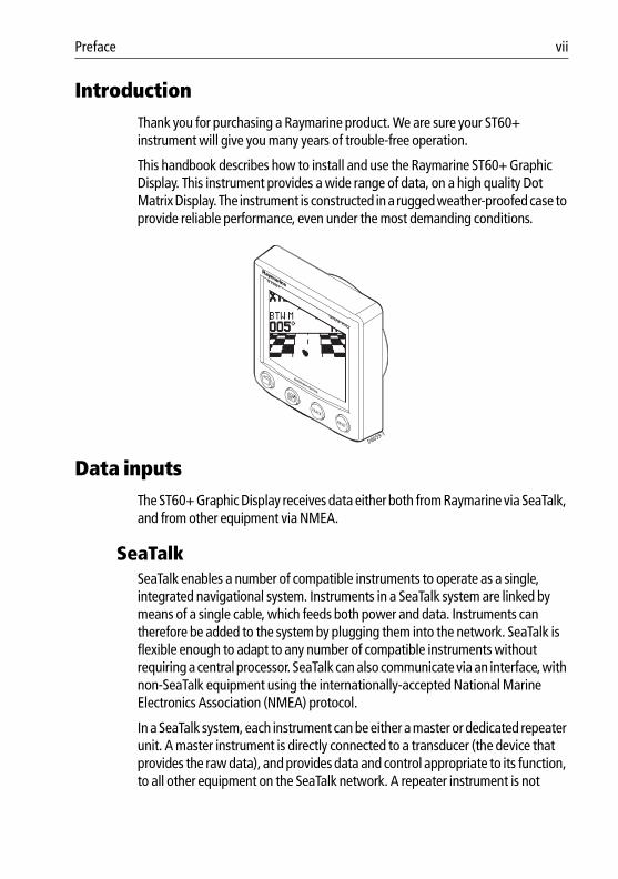
This handbook describes how to install and use the Raymarine ST60+ Graphic Display. This instrument provides a wide range of data, on a high quality Dot Matrix Display. The instrument is constructed in a rugged weather-proofed case to provide reliable performance, even under the most demanding conditions.
Data inputsThe ST60+ Graphic Display receives data either both from Raymarine via SeaTalk, and from other equipment via NMEA.
SeaTalkSeaTalk enables a number of compatible instruments to operate as a single, integrated navigational system. Instruments in a SeaTalk system are linked by means of a single cable, which feeds both power and data. Instruments can therefore be added to the system by plugging them into the network. SeaTalk is flexible enough to adapt to any number of compatible instruments without requiring a central processor. SeaTalk can also communicate via an interface, with non-SeaTalk equipment using the internationally-accepted National Marine Electronics Association (NMEA) protocol.
In a SeaTalk system, each instrument can be either a master or dedicated repeater unit. A master instrument is directly connected to a transducer (the device that provides the raw data), and provides data and control appropriate to its function, to all other equipment on the SeaTalk network. A repeater instrument is not
D8659-1
GRAPHIC
ST60+
TRACK
RESET

viii ST60+ Graphic Display Owner’s Handbook
81268_2.book Page viii Monday, December 5, 2005 9:44 AM
directly connected to a transducer but displays information provided by other equipment in the SeaTalk network.
The ST60+ Graphic Display is a repeater.
Remote controlThe ST60+ Graphic Display does not support the SeaTalk Remote remote control function.
Mounting optionsA standard ST60+ instrument is surface-mounted at the required location. If you do not want to surface mount your ST60+ Graphic Display, options are available for:• Flush mounting. If you have ordered the flush mounting option a low-profile
bezel and four fixing screws are provided.• Bracket mounting.
Preface ix
81268_2.book Page ix Monday, December 5, 2005 9:44 AM
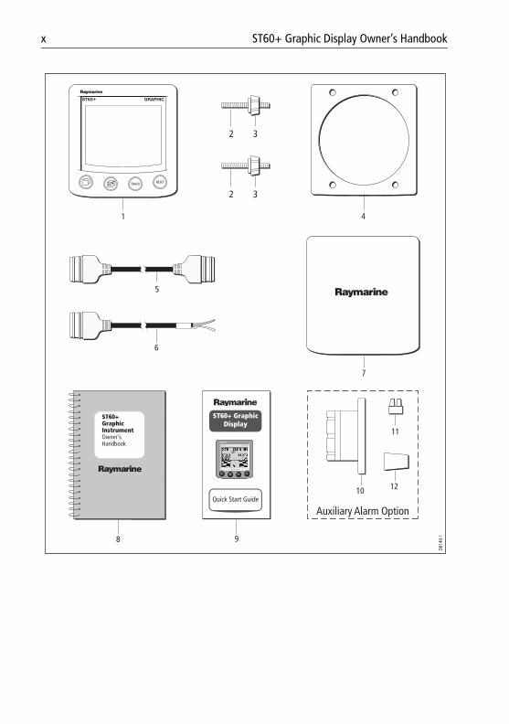
Parts suppliedUnpack your ST60+ Graphic Display and check that the following items are present:• Item 1, ST60+ Graphic Display fitted with standard bezel for surface
mounting.• Item 2, Fixing studs (2).• Item 3, Thumb nuts (2).• Item 4, Gasket.• Item 5, SeaTalk interconnection cable.• Item 6, Power cable.• Item 7, Instrument Cover.• Item 8, Owner’s Handbook. A Warranty document and fitting
templates are included in this Handbook.• Item 9, Quick Start Guide.
If the Auxiliary Alarm option has also been supplied, check that the following items are also included:• Item 10, Auxiliary Alarm.• Item 11, Connector block.• Item 12, Grommet.
x ST60+ Graphic Display Owner’s Handbook
81268_2.book Page x Monday, December 5, 2005 9:44 AM
ST60+ GraphicInstrumentOwner'sHandbook
1 4
8
5
6
7
9
10
11
12
D814
0-1
Auxiliary Alarm Option
32
32
Quick Start Guide
ST60+ Graphic Display
ST60 + GRAPHIC+

1
81268_2.book Page 1 Monday, December 5, 2005 9:44 AM
Chapter 1: Operation
1.1 Getting started
Displayed informationYour ST60+ Graphic Display uses a high-quality dot-matrix screen to display a wide range of data, both from Raymarine via SeaTalk, and from other equipment via NMEA. The exact information available for display depends on what data is available and on how the display has been set up.
The ST60+ Graphic Display can also supply SeaTalk data to NMEA 0183.
Switching on and offAll the time that power is applied to the instrument, you can use the button to switch the instrument off and on as follows:• To switch the instrument off, hold down the button for approximately
5 seconds. After this time, a switch off count down of 4 seconds occurs. Keep the button pressed during this period, to switch off the instrument.
• To switch the instrument back on, hold down the button for approxi-mately 1 second.
When the power supply is switched off, none of the instrument buttons (including ) has any effect.
Notes: (1) Each time power to the instrument is switched on, the instrument is ini-tially in the on condition. You do not need to use the button to switch the instrument on.
(2) When the instrument is on, the operation of the button will perform other operating functions, as described below.
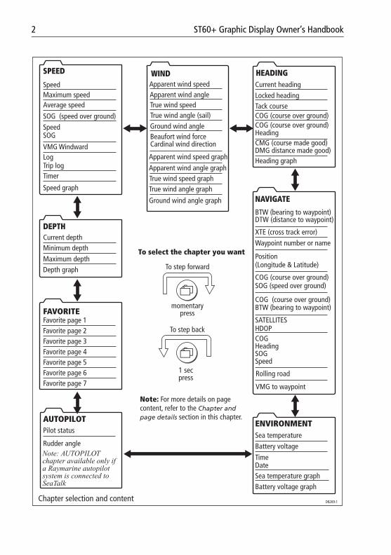
1.2 Accessing informationInformation on the ST60+ Graphic Display is organized in groups or ‘chapters’, and within each chapter, the different types of information are presented as pages. The ST60+ Graphic Display chapters and pages are shown in the following Chapter selection and content illustration. This illustration assumes a system where all information sources are available and all pages are enabled.
WARNING: Calibration requirementTo ensure this product performs at its best on your boat, you MUST calibrate it before use, in accordance with the instructions in Chapter 4, Calibration. Do NOT use the product until you have successfully calibrated it.
2 ST60+ Graphic Display Owner’s Handbook
81268_2.book Page 2 Monday, December 5, 2005 9:44 AM
Speed graph
VMG Windward
Maximum speedSpeed
Speed
Average speed
LogTrip log
SOG (speed over ground)
SOG
Timer
SPEED
True wind speed graphApparent wind angle graph
Ground wind angle graph
Apparent wind speed graph
True wind angle graph
Ground wind angleBeaufort wind forceCardinal wind direction
WINDApparent wind speed
True wind speedApparent wind angle
True wind angle (sail)
Heading graph
Tack course
DMG distance made good)CMG (course made good)
COG (course over ground)
Locked headingCurrent heading
HeadingCOG (course over ground)
HEADING
SATELLITESHDOP
NAVIGATE
BTW (bearing to waypoint) DTW (distance to waypoint)
Speed
Position
COG (course over ground)
COG (course over ground)BTW (bearing to waypoint)
COGHeadingSOG
XTE (cross track error)
(Longitude & Latitude)
SOG (speed over ground)
Waypoint number or name
Rolling road
VMG to waypoint
Sea temperature graphBattery voltage graph
ENVIRONMENTSea temperatureBattery voltage
DateTime
Depth graph
Minimum depthMaximum depth
FAVORITE
Favorite page 5Favorite page 4
Favorite page 7Favorite page 6
Favorite page 3Favorite page 2Favorite page 1
Current depthDEPTH
Pilot status
Rudder angle
AUTOPILOT
Note: AUTOPILOT chapter available only if a Raymarine autopilot system is connected to SeaTalk
To select the chapter you want
momentary press
1 sec press
Chapter selection and content
Note: For more details on page content, refer to the Chapter and page details section in this chapter.
To step forward
To step back
D8269-1
Chapter 1: Operation 3
81268_2.book Page 3 Monday, December 5, 2005 9:44 AM
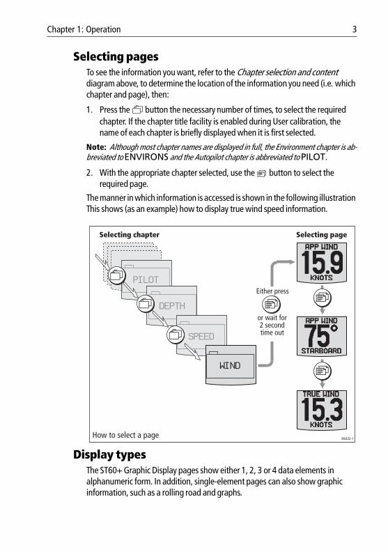
Selecting pagesTo see the information you want, refer to the Chapter selection and content diagram above, to determine the location of the information you need (i.e. which chapter and page), then:
1. Press the button the necessary number of times, to select the required chapter. If the chapter title facility is enabled during User calibration, the name of each chapter is briefly displayed when it is first selected.
Note: Although most chapter names are displayed in full, the Environment chapter is ab-breviated to ENVIRONS and the Autopilot chapter is abbreviated to PILOT.
2. With the appropriate chapter selected, use the button to select the required page.
The manner in which information is accessed is shown in the following illustration This shows (as an example) how to display true wind speed information.
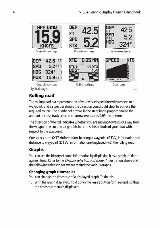
Display typesThe ST60+ Graphic Display pages show either 1, 2, 3 or 4 data elements in alphanumeric form. In addition, single-element pages can also show graphic information, such as a rolling road and graphs.
Selecting chapter Selecting page
How to select a page D6432-1
or wait for2 secondtime out
Either pressPILOT
DEPTH
SPEED
WIND
4 ST60+ Graphic Display Owner’s Handbook
81268_2.book Page 4 Monday, December 5, 2005 9:44 AM
Rolling roadThe rolling road is a representation of your vessel’s position with respect to a waypoint, and a steer bar shows the direction you should steer to achieve the required course. The number of arrows in the steer bar is proportional to the amount of cross track error; each arrow represents 0.05 nm of error.
The direction of the roll indicates whether you are moving towards or away from the waypoint. A small boat graphic indicates the attitude of your boat with respect to the waypoint.
Cross track error (XTE) information, bearing to waypoint (BTW) information and distance to waypoint (DTW) information are displayed with the rolling road.
GraphsYou can see the history of some information by displaying it as a graph, of data against time. Refer to the Chapter selection and content illustration above and the following tables to see where to find the various graphs.
Changing graph timescalesYou can change the timescale of a displayed graph. To do this:1. With the graph displayed, hold down the reset button for 1 second, so that
the timescale menu is displayed.
Typical pages D6433-1
Single-element page Dual-element page Triple-element page
Quad-element page Rolling road page Graph page
Chapter 1: Operation 5
81268_2.book Page 5 Monday, December 5, 2005 9:44 AM
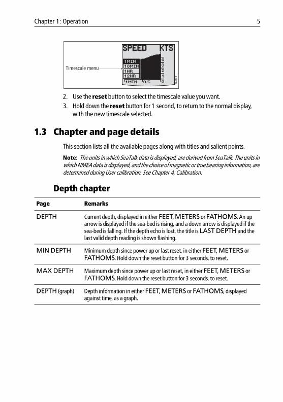
2. Use the reset button to select the timescale value you want.3. Hold down the reset button for 1 second, to return to the normal display,
with the new timescale selected.
1.3 Chapter and page detailsThis section lists all the available pages along with titles and salient points.
Note: The units in which SeaTalk data is displayed, are derived from SeaTalk. The units in which NMEA data is displayed, and the choice of magnetic or true bearing information, are determined during User calibration. See Chapter 4, Calibration.
Depth chapter
Page Remarks
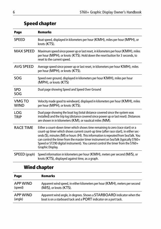
DEPTH Current depth, displayed in either FEET, METERS or FATHOMS. An up arrow is displayed if the sea-bed is rising, and a down arrow is displayed if the sea-bed is falling. If the depth echo is lost, the title is LAST DEPTH and the last valid depth reading is shown flashing.
MIN DEPTH Minimum depth since power up or last reset, in either FEET, METERS or FATHOMS. Hold down the reset button for 3 seconds, to reset.
MAX DEPTH Maximum depth since power up or last reset, in either FEET, METERS or FATHOMS. Hold down the reset button for 3 seconds, to reset.
DEPTH (graph) Depth information in either FEET, METERS or FATHOMS, displayed against time, as a graph.
D648
2-1
Timescale menu
6 ST60+ Graphic Display Owner’s Handbook
81268_2.book Page 6 Monday, December 5, 2005 9:44 AM
Speed chapter
Wind chapter
Page Remarks
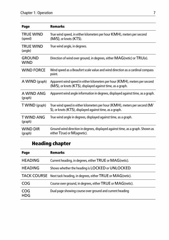
SPEED Boat speed, displayed in kilometers per hour (KMH), miles per hour (MPH), or knots (KTS).
MAX SPEED Maximum speed since power up or last reset, in kilometers per hour (KMH), miles per hour (MPH), or knots (KTS). Hold down the reset button for 3 seconds, to reset to the current speed.
AVG SPEED Average speed since power up or last reset, in kilometers per hour KMH), miles per hour (MPH), or knots (KTS).
SOG Speed over ground, displayed in kilometers per hour KMH), miles per hour (MPH), or knots (KTS)
SPDSOG
Dual page showing Speed and Speed Over Ground
VMG TO WIND
Velocity made good to windward, displayed in kilometers per hour (KMH), miles per hour (MPH), or knots (KTS).
LOGTRIP
Dual page showing the boat log (total distance covered since the system was installed) and the trip log (distance covered since power up or last reset). Distances are shown in in kilometers (KM), or nautical miles (NM).
RACE TIME Either a count-down timer which shows time remaining to zero (race start) or a count-up timer which shows current count-up time (after race start), in either sec-onds (S), minutes (M) or hours (H). This information is repeated from SeaTalk. You can control the timer from the master timer instrument on SeaTalk (typically ST60+ Speed or ST290 digital instrument). You cannot control the timer from the ST60+ Graphic Display.
SPEED (graph) Speed information in kilometers per hour (KMH), meters per second (M/S), or knots (KTS), displayed against time, as a graph.
Page Remarks
APP WIND (speed)
Apparent wind speed, in either kilometers per hour (KMH), meters per second (M/S), or knots (KTS).
APP WIND (angle)
Apparent wind angle, in degrees. Shows a STARBOARD indicator when the boat is on a starboard tack and a PORT indicator on a port tack.
Chapter 1: Operation 7
81268_2.book Page 7 Monday, December 5, 2005 9:44 AM
Heading chapter
TRUE WIND (speed)
True wind speed, in either kilometers per hour KMH), meters per second(M/S), or knots (KTS).
TRUE WIND (angle)
True wind angle, in degrees.
GROUND WIND
Direction of wind over ground, in degrees, either MAG(netic) or TRU(e).
WIND FORCE Wind speed as a Beaufort scale value and wind direction as a cardinal compass point.
A WIND (graph) Apparent wind speed in either kilometers per hour (KMH), meters per second (M/S), or knots (KTS), displayed against time, as a graph.
A WIND ANG (graph)
Apparent wind angle information in degrees, displayed against time, as a graph.
T WIND (graph) True wind speed in either kilometers per hour (KMH), meters per second (M/S), or knots (KTS), displayed against time, as a graph.
T WIND ANG (graph)
True wind angle in degrees, displayed against time, as a graph.
WIND DIR (graph)
Ground wind direction in degrees, displayed against time, as a graph. Shown as either T(rue) or M(agnetic).
Page Remarks
HEADING Current heading, in degrees, either TRUE or MAG(netic).
HEADING Shows whether the heading is LOCKED or UNLOCKED.
TACK COURSE Next tack heading, in degrees, either TRUE or MAG(netic).
COG Course over ground, in degrees, either TRUE or MAG(netic).
COGHDG
Dual page showing course over ground and current heading
Page Remarks
8 ST60+ Graphic Display Owner’s Handbook
81268_2.book Page 8 Monday, December 5, 2005 9:44 AM
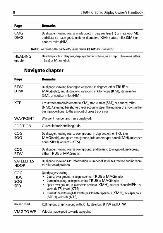
Navigate chapter
CMGDMG
Dual page showing course made good, in degrees, true (T) or magnetic (M), and distance made good, in either kilometers (KM), statute miles (SM), or nautical miles (NM).
Note: To reset CMG and DMG, hold down reset for 3 seconds.
HEADING (graph)
Heading angle in degrees, displayed against time, as a graph. Shown as either T(rue) or M(agnetic).
Page Remarks
BTWDTW
Dual page showing bearing to waypoint, in degrees, ether TRUE or MAG(netic), and distance to waypoint, in kilometers (KM), statue miles (SM), or nautical miles (NM).
XTE Cross track error in kilometers (KM), statue miles (SM), or nautical miles (NM). A steering bar shows the direction to steer. The number of arrows in the bar is proportional to the amount of cross track error.
WAYPOINT Waypoint number and name displayed.
POSITION Current latitude and longitude.
COGSOG
Dual page showing course over ground, in degrees, either TRUE or MAG(netic), and speed over ground, in kilometers per hour (KMH), miles per hour (MPH), or knots (KTS).
COGBTW
Dual page showing course over ground, and bearing to waypoint, in degrees, either TRUE or MAG(netic)
SATELLITESHDOP
Dual page showing GPS information. Number of satellites tracked and horizon-tal dilution of position.
COGHDGSOGSPD
Quad page showing:• Course over ground, in degrees, either TRUE or MAG(netic).• Current heading, in degrees, either TRUE or MAG(netic).• Speed over ground, in kilometers per hour (KMH), miles per hour (MPH), or
knots (KTS).knots (KTS).• Current speed through the water, in kilometers per hour (KMH), miles per hour.
(MPH), or knots (KTS).
Rolling road Rolling road graphic along with XTE, steer bar, BTW and DTW.
VMG TO WP Velocity made good towards waypoint
Page Remarks
Chapter 1: Operation 9
81268_2.book Page 9 Monday, December 5, 2005 9:44 AM
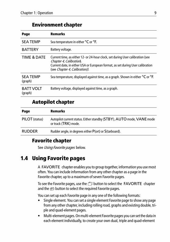
Environment chapter
Autopilot chapter
Favorite chapter See Using Favorite pages below.
1.4 Using Favorite pagesA FAVORITE chapter enables you to group together, information you use most often. You can include information from any other chapter as a page in the Favorite chapter, up to a maximum of seven Favorite pages.
To see the Favorite pages, use the button to select the FAVORITE chapter and the button to select the required Favorite pages.
You can set up each Favorite page in any one of the following formats:• Single element. You can set a single element Favorite page to show any page
from any other chapter, including rolling road, graphs and existing double, tri-ple and quad-element pages.
• Multi-element pages. On multi-element Favorite pages you can set the data in each element individually, to create your own dual, triple and quad-element
Page Remarks
SEA TEMP Sea temperature in either °C or °F.
BATTERY Battery voltage.
TIME & DATE Current time, as either 12- or 24-hour clock, set during User calibration (see Chapter 4, Calibration). Current date, in either USA or European format, as set during User calibration (see Chapter 4, Calibration)).
SEA TEMP (graph)
Sea temperature, displayed against time, as a graph. Shown in either °C or °F.
BATT VOLT (graph)
Battery voltage, displayed against time, as a graph.
Page Remarks
PILOT (status) Autopilot current status. Either standby (STBY), AUTO mode, VANE mode or track (TRK) mode.
RUDDER Rudder angle, in degrees either P(ort) or S(tarboard).
10 ST60+ Graphic Display Owner’s Handbook
81268_2.book Page 10 Monday, December 5, 2005 9:44 AM
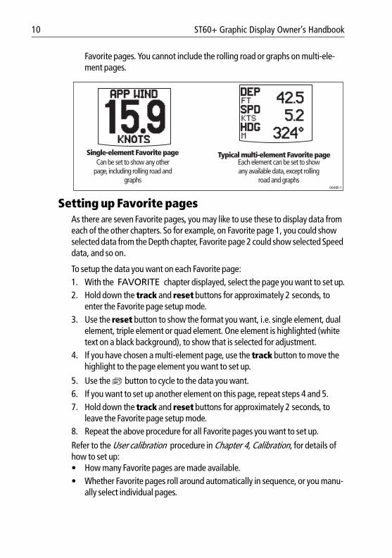
Favorite pages. You cannot include the rolling road or graphs on multi-ele-ment pages.
Setting up Favorite pagesAs there are seven Favorite pages, you may like to use these to display data from each of the other chapters. So for example, on Favorite page 1, you could show selected data from the Depth chapter, Favorite page 2 could show selected Speed data, and so on.
To setup the data you want on each Favorite page:1. With the FAVORITE chapter displayed, select the page you want to set up.2. Hold down the track and reset buttons for approximately 2 seconds, to
enter the Favorite page setup mode.3. Use the reset button to show the format you want, i.e. single element, dual
element, triple element or quad element. One element is highlighted (white text on a black background), to show that is selected for adjustment.
4. If you have chosen a multi-element page, use the track button to move the highlight to the page element you want to set up.
5. Use the button to cycle to the data you want.6. If you want to set up another element on this page, repeat steps 4 and 5.7. Hold down the track and reset buttons for approximately 2 seconds, to
leave the Favorite page setup mode.8. Repeat the above procedure for all Favorite pages you want to set up.
Refer to the User calibration procedure in Chapter 4, Calibration, for details of how to set up:• How many Favorite pages are made available.• Whether Favorite pages roll around automatically in sequence, or you manu-
ally select individual pages.
Single-element Favorite pageCan be set to show any other
page, including rolling road and graphs
Each element can be set to show any available data, except rolling
road and graphs
Typical multi-element Favorite page
D6480-1
Chapter 1: Operation 11
81268_2.book Page 11 Monday, December 5, 2005 9:44 AM
1.5 Autopilot informationIf a Raymarine Autopilot is connected to SeaTalk, you can use the Autopilot chapter to show the current pilot status. During User calibration (see Chapter 4, Calibration ), you can also set the ST60+ Graphic Display to show the autopilot status on pop-up pages, whenever the autopilot status changes,. Examples of instances when a pilot pop-up can occur are:• Engage autopilot • Disengage autopilot• Change of course• Enter track mode• Enter vane mode
Autopilot pop-up pages have a border to distinguish them from the other pages, and are displayed for 5 seconds.
1.6 Using the track button If your system includes a SeaTalk autopilot working in conjunction with a track plotter, you can operate the track plotter in track mode, as follows:1. Press the track button once, so the track plotter enters track mode.2. In track mode, to plot a track to the next waypoint, hold down the track but-
ton for 1 second.3. To leave track mode, press the track button again.
1.7 Alarm messagesThe ST60+ Graphic Display supports a range of SeaTalk alarm signals and responds with an internal buzzer and an appropriate on-screen alarm message.
In addition to this, the ST60+ Graphic Display can also provide external alarm signals for the Auxiliary Alarm option.
The range of available alarms depends on:• What data is available on SeaTalk.• Which alarms are enabled during User calibration (see Chapter 4,
Calibration ).
12 ST60+ Graphic Display Owner’s Handbook
81268_2.book Page 12 Monday, December 5, 2005 9:44 AM
Internal alarmsThe internal alarms are as follows:
External alarmsAn optional Auxiliary Alarm can be fitted at a convenient remote position, to give a loud, audible indication if any one of a range of alarms occurs. This option is particularly useful for situations where high ambient noise may make it difficult to hear the instrument’s internal alarm (e.g. aboard a power boat).
Note: An Auxiliary Alarm cannot be used if the NMEA OUT port is being used for NMEA data.
Actions to take if an alarm occursIf an alarm occurs, investigate the cause immediately and if possible, take appropriate action to remove the cause. If an alarm message is displayed, use this to guide your course of action.
Silencing internal alarmsYou can silence an internal alarm by pressing any one of the ST60+ Graphic Display front panel buttons. Remember though, that removing the alarm sound does not remove the cause of an alarm. If the alarm condition persists, the alarm will recur.
Message Meaning
ANCHOR ALARM (with current depth) Deep or shallow anchor alarm
SHALLOW ALARM (with current depth) Shallow water alarm
DEEP ALARM (with current depth) Deep water alarm
HIGH WIND ALARM (with current wind speed)
High wind speed alarm
RADAR ALARM Radar guard zone alarm
LOST FIX ALARM Lost fix alarm
LOW BATTERY ALARM (with current voltage)
The battery voltage has fallen below the specified low-voltage level.
Chapter 1: Operation 13
81268_2.book Page 13 Monday, December 5, 2005 9:44 AM
Silencing external alarmsMost external alarms can be silenced only at the alarm-initiating device e.g. autopilot, GPS or master instrument. Exceptions to this are the LOST FIX ALARM and the LOW BATTERY ALARM , which can be silenced by pressing any of the ST60+ Graphic Display front panel buttons.
1.8 Display settings
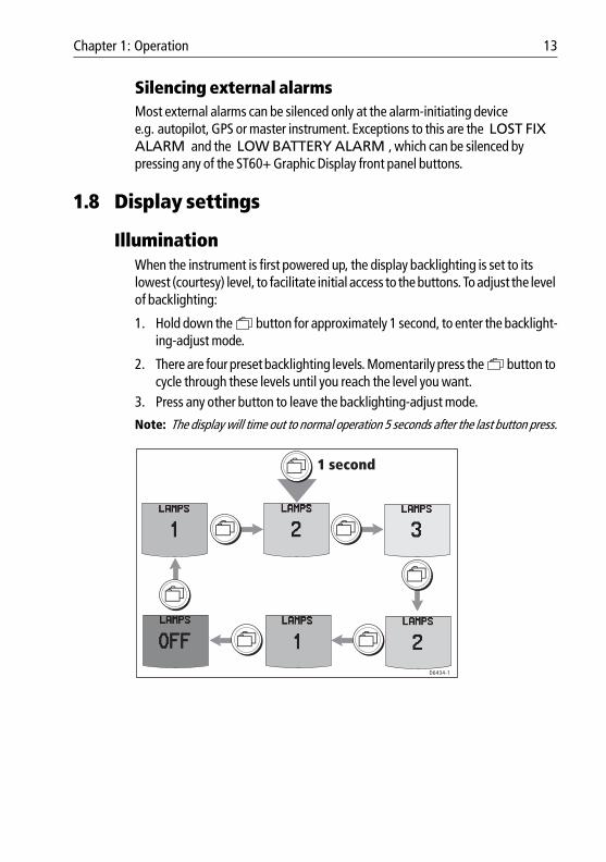
IlluminationWhen the instrument is first powered up, the display backlighting is set to its lowest (courtesy) level, to facilitate initial access to the buttons. To adjust the level of backlighting:
1. Hold down the button for approximately 1 second, to enter the backlight-ing-adjust mode.
2. There are four preset backlighting levels. Momentarily press the button to cycle through these levels until you reach the level you want.
3. Press any other button to leave the backlighting-adjust mode.
Note: The display will time out to normal operation 5 seconds after the last button press.
1 second
D6434-1
14 ST60+ Graphic Display Owner’s Handbook
81268_2.book Page 14 Monday, December 5, 2005 9:44 AM
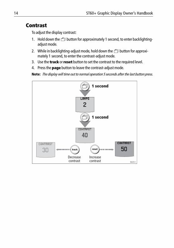
ContrastTo adjust the display contrast:
1. Hold down the button for approximately 1 second, to enter backlighting-adjust mode.
2. While in backlighting-adjust mode, hold down the button for approxi-mately 1 second, to enter the contrast-adjust mode.
3. Use the track or reset button to set the contrast to the required level.4. Press the page button to leave the contrast-adjust mode.
Note: The display will time out to normal operation 5 seconds after the last button press.
Decrease contrast
Increase contrast
LAMPS
resettrack
1 second
1 second
D6435-1
15
81268_2.book Page 15 Monday, December 5, 2005 9:44 AM
Chapter 2: Maintenance & Troubleshooting
2.1 Maintenance
Servicing and safety• Raymarine equipment should be serviced only by authorised Raymarine ser-
vice technicians. They will ensure that servicing procedures and replacement parts used will not affect performance. There are no user-serviceable parts in any Raymarine product.
• Some products generate high voltages, and so never handle the cables/con-nectors when power is being applied to the equipment.
• When powered up, all electrical equipment produces electromagnetic fields. These can cause adjacent pieces of electrical equipment to interact with one another, with a consequent adverse effect on operation. In order to minimise these effects and enable you to get the best possible performance from your Raymarine equipment, guidelines are given in the installation instructions, to enable you to ensure minimum interaction between different items of equip-ment, i.e. ensure optimum Electromagnetic Compatibility (EMC).
• Always report any EMC-related problem to your nearest Raymarine dealer. We use such information to improve our quality standards.
• In some installations, it may not be possible to prevent the equipment from being affected by external influences. In general this will not damage the equipment but it can lead to spurious resetting action, or momentarily may result in faulty operation.
InstrumentCertain atmospheric conditions may cause condensation to form on the instrument window. This will not harm the instrument and can be cleared by increasing the illumination setting to Level 3.
CleaningDo not use chemical or abrasive materials to clean your instrument. Do not wipe the instrument with a dry cloth as this could cause scratches.
Periodically clean your ST60+ Graphic Display with a soft damp cloth.
CablingPeriodically examine all cables for chafing or other damage to the outer shield, and where necessary, replace and re-secure.
16 ST60+ Graphic Display Owner’s Handbook
81268_2.book Page 16 Monday, December 5, 2005 9:44 AM
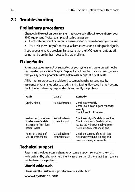
2.2 Troubleshooting
Preliminary proceduresChanges in the electronic environment may adversely affect the operation of your ST60 equipment. Typical examples of such changes are:• Electrical equipment has recently been installed or moved aboard your vessel.• You are in the vicinity of another vessel or shore station emitting radio signals.
If you appear to have a problem, first ensure that the EMC requirements are still being met before further investigating the problem.
Fixing faultsSome data types may not be supported by your system and therefore will not be displayed on your ST60+ Graphic Display. If you think that data is missing, ensure that your system supports this data before assuming that a fault exists.
All Raymarine products are subjected to comprehensive test and quality assurance programmes prior to packing and shipping. However, if a fault occurs, the following table may help to identify and rectify the problem.
Technical supportRaymarine provides a comprehensive customer support service, on the world wide web and by telephone help line. Please use either of these facilities if you are unable to rectify a problem.
World wide webPlease visit the Customer Support area of our web site at:www.raymarine.com
Fault Cause Remedy
Display blank. No power supply. Check power supply.Check SeaTalk cabling and connector security.Check fuse/circuit breaker.
No transfer of informa-tion between SeaTalk instruments (e.g. illumi-nation levels).
SeaTalk cable or connector fault.
Check security of SeaTalk connectors.Check condition of SeaTalk cables.Isolate faulty instrument by discon-necting instruments one by one.
Failure of a group of SeaTalk instruments.
SeaTalk cable or connector fault.
Check the security of SeaTalk con-nectors between functioning and non-functioning instruments.
Chapter 2: Maintenance & Troubleshooting 17
81268_2.book Page 17 Monday, December 5, 2005 9:44 AM
As well as providing a comprehensive Frequently Asked Questions section and servicing information, the web site gives e-mail access to the Raymarine Technical Support Department and a details of the locations of Raymarine agents, worldwide.
Telephone help lineIf you do not have access to the world wide web, please call our help line.
In the USA, call:• +1 800 539 5539, extension 2444 or• +1 603 881 5200 extension 2444
In the UK, Europe the Middle East or the Far East, call:• +44 (0) 23 9271 4713 (voice)• +44 (0) 23 9266 1228 (fax)
Help us to help youWhen requesting service, please quote the following product information:• Equipment type.• Model number.• Serial number.• Software issue number.
The Software issue number can be ascertained by means of the Intermediate Calibration facility, see Chapter 4, Calibration.
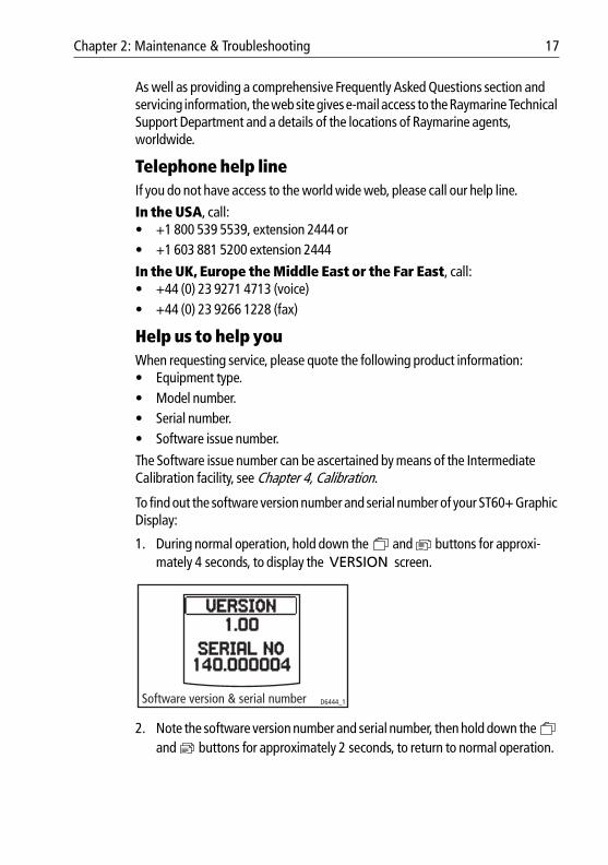
To find out the software version number and serial number of your ST60+ Graphic Display:
1. During normal operation, hold down the and buttons for approxi-mately 4 seconds, to display the VERSION screen.
2. Note the software version number and serial number, then hold down the and buttons for approximately 2 seconds, to return to normal operation.
Software version & serial number D6444_1

18 ST60+ Graphic Display Owner’s Handbook
81268_2.book Page 18 Monday, December 5, 2005 9:44 AM
19
81268_2.book Page 19 Monday, December 5, 2005 9:44 AM
Chapter 3: InstallationThis chapter describes how to install the ST60+ Graphic Display.
For advice, or further information regarding the installation of this equipment, please contact the Raymarine Product Support Department or your own National Distributor.
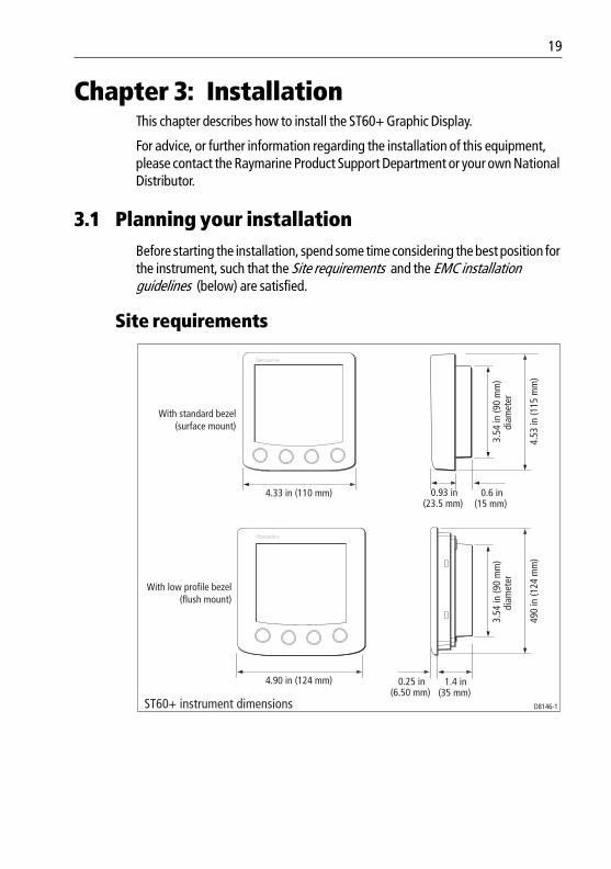
3.1 Planning your installationBefore starting the installation, spend some time considering the best position for the instrument, such that the Site requirements and the EMC installation guidelines (below) are satisfied.
Site requirements
4.33 in (110 mm) 0.93 in(23.5 mm)
0.6 in(15 mm)
3.54
in (9
0 m
m)
diam
eter
4.53
in (1
15 m
m)
4.90 in (124 mm) 0.25 in(6.50 mm)
1.4 in(35 mm)
3.54
in (9
0 m
m)
diam
eter
490
in (1
24 m
m)
D8146-1ST60+ instrument dimensions
With standard bezel (surface mount)
With low profile bezel (flush mount)
20 ST60+ Graphic Display Owner’s Handbook
81268_2.book Page 20 Monday, December 5, 2005 9:44 AM
ST60+ instruments can be fitted either above or below deck, provided the rear of the instrument is sited where it is protected from contact with water.
Each instrument must also be positioned where:• It is easily read by the helmsman.• It is protected against physical damage.• It is at least 9 in (230 mm) from a compass.• It is at least 20 in (500 mm) from radio receiving equipment.• There is reasonable rear access for installation and servicing.
EMC installation guidelinesAll Raymarine equipment and accessories are designed to the best industry standards for use in the recreational marine environment.
Their design and manufacture conforms to the appropriate Electromagnetic Compatibility (EMC) standards, but correct installation is required to ensure that performance is not compromised. Although every effort has been taken to ensure that they will perform under all conditions, it is important to understand what factors could affect the operation of the product.
The guidelines given here describe the conditions for optimum EMC performance, but it is recognized that it may not be possible to meet all of these conditions in all situations. To ensure the best possible conditions for EMC performance within the constraints imposed by any location, always ensure the maximum separation possible between different items of electrical equipment.
For optimum EMC performance, it is recommended that wherever possible:• Raymarine equipment and cables connected to it are:
• At least 3 ft (1 m) from any equipment transmitting or cables carrying radio signals e.g. VHF radios, cables and antennas. In the case of SSB radios, the distance should be increased to 7 ft (2 m).
• More than 7 ft (2 m) from the path of a radar beam. A radar beam can nor-mally be assumed to spread 20 degrees above and below the radiating element.
• The equipment is supplied from a separate battery from that used for engine start. Voltage drops below 10 V in the power supply to our products, and
CAUTION: Keep the rear of The instrument dryKeep the rear of the instrument dry. Failure to observe this caution could result in damage if water enters the instrument through the breathing hole or comes into contact with the electrical connectors.
Chapter 3: Installation 21
81268_2.book Page 21 Monday, December 5, 2005 9:44 AM
starter motor transients, can cause the equipment to reset. This will not dam-age the equipment, but may cause the loss of some information and may change the operating mode.
• Raymarine specified cables are used. Cutting and rejoining these cables can compromise EMC performance and must be avoided unless doing so is detailed in the installation manual.
• If a suppression ferrite is attached to a cable, this ferrite should not be removed. If the ferrite needs to be removed during installation it must be reas-sembled in the same position.
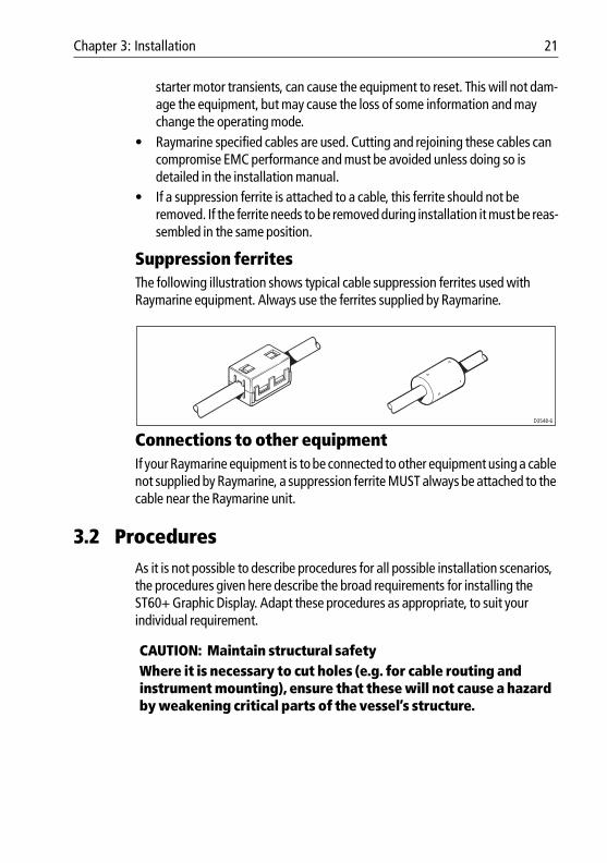
Suppression ferritesThe following illustration shows typical cable suppression ferrites used with Raymarine equipment. Always use the ferrites supplied by Raymarine.
Connections to other equipmentIf your Raymarine equipment is to be connected to other equipment using a cable not supplied by Raymarine, a suppression ferrite MUST always be attached to the cable near the Raymarine unit.
3.2 ProceduresAs it is not possible to describe procedures for all possible installation scenarios, the procedures given here describe the broad requirements for installing the ST60+ Graphic Display. Adapt these procedures as appropriate, to suit your individual requirement.
CAUTION: Maintain structural safetyWhere it is necessary to cut holes (e.g. for cable routing and instrument mounting), ensure that these will not cause a hazard by weakening critical parts of the vessel’s structure.
D3548-6
22 ST60+ Graphic Display Owner’s Handbook
81268_2.book Page 22 Monday, December 5, 2005 9:44 AM
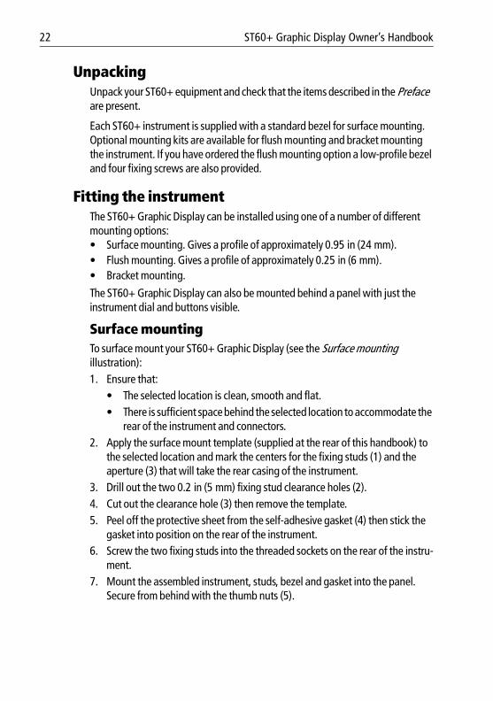
UnpackingUnpack your ST60+ equipment and check that the items described in the Preface are present.
Each ST60+ instrument is supplied with a standard bezel for surface mounting. Optional mounting kits are available for flush mounting and bracket mounting the instrument. If you have ordered the flush mounting option a low-profile bezel and four fixing screws are also provided.
Fitting the instrumentThe ST60+ Graphic Display can be installed using one of a number of different mounting options:• Surface mounting. Gives a profile of approximately 0.95 in (24 mm).• Flush mounting. Gives a profile of approximately 0.25 in (6 mm).• Bracket mounting.
The ST60+ Graphic Display can also be mounted behind a panel with just the instrument dial and buttons visible.
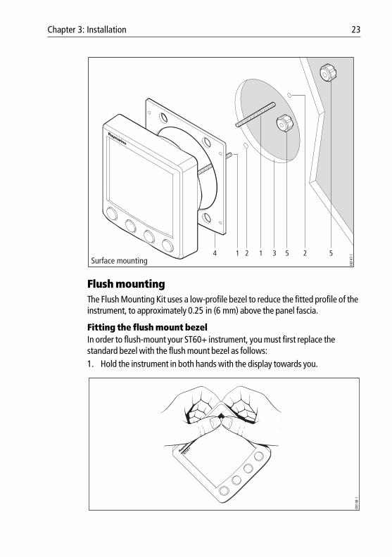
Surface mountingTo surface mount your ST60+ Graphic Display (see the Surface mounting illustration):1. Ensure that:
• The selected location is clean, smooth and flat.• There is sufficient space behind the selected location to accommodate the
rear of the instrument and connectors.2. Apply the surface mount template (supplied at the rear of this handbook) to
the selected location and mark the centers for the fixing studs (1) and the aperture (3) that will take the rear casing of the instrument.
3. Drill out the two 0.2 in (5 mm) fixing stud clearance holes (2).4. Cut out the clearance hole (3) then remove the template.5. Peel off the protective sheet from the self-adhesive gasket (4) then stick the
gasket into position on the rear of the instrument.6. Screw the two fixing studs into the threaded sockets on the rear of the instru-
ment.7. Mount the assembled instrument, studs, bezel and gasket into the panel.
Secure from behind with the thumb nuts (5).
Chapter 3: Installation 23
81268_2.book Page 23 Monday, December 5, 2005 9:44 AM
Flush mountingThe Flush Mounting Kit uses a low-profile bezel to reduce the fitted profile of the instrument, to approximately 0.25 in (6 mm) above the panel fascia.
Fitting the flush mount bezelIn order to flush-mount your ST60+ instrument, you must first replace the standard bezel with the flush mount bezel as follows:1. Hold the instrument in both hands with the display towards you.
Surface mounting4 1 2 1 3 5 52
D814
7-1
D814
8-1
24 ST60+ Graphic Display Owner’s Handbook
81268_2.book Page 24 Monday, December 5, 2005 9:44 AM
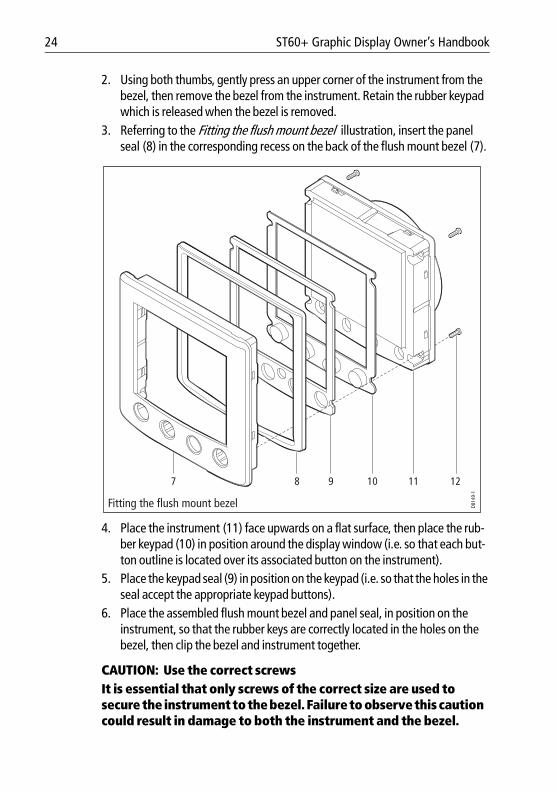
2. Using both thumbs, gently press an upper corner of the instrument from the bezel, then remove the bezel from the instrument. Retain the rubber keypad which is released when the bezel is removed.
3. Referring to the Fitting the flush mount bezel illustration, insert the panel seal (8) in the corresponding recess on the back of the flush mount bezel (7).
4. Place the instrument (11) face upwards on a flat surface, then place the rub-ber keypad (10) in position around the display window (i.e. so that each but-ton outline is located over its associated button on the instrument).
5. Place the keypad seal (9) in position on the keypad (i.e. so that the holes in the seal accept the appropriate keypad buttons).
6. Place the assembled flush mount bezel and panel seal, in position on the instrument, so that the rubber keys are correctly located in the holes on the bezel, then clip the bezel and instrument together.
CAUTION: Use the correct screwsIt is essential that only screws of the correct size are used to secure the instrument to the bezel. Failure to observe this caution could result in damage to both the instrument and the bezel.
Fitting the flush mount bezel
87 9 10 11 12D8
149-
1
Chapter 3: Installation 25
81268_2.book Page 25 Monday, December 5, 2005 9:44 AM
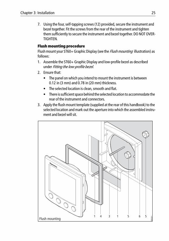
7. Using the four, self-tapping screws (12) provided, secure the instrument and bezel together. Fit the screws from the rear of the instrument and tighten them sufficiently to secure the instrument and bezel together. DO NOT OVER-TIGHTEN.
Flush mounting procedureFlush mount your ST60+ Graphic Display (see the Flush mounting illustration) as follows:1. Assemble the ST60+ Graphic Display and low-profile bezel as described
under Fitting the low-profile bezel.2. Ensure that:
• The panel on which you intend to mount the instrument is between 0.12 in (3 mm) and 0.78 in (20 mm) thickness.
• The selected location is clean, smooth and flat.• There is sufficient space behind the selected location to accommodate the
rear of the instrument and connectors.3. Apply the flush mount template (supplied at the rear of this handbook) to the
selected location and mark out the aperture into which the assembled instru-ment and bezel will sit.
Flush mounting41 3 5 6 51
D815
0-1
26 ST60+ Graphic Display Owner’s Handbook
81268_2.book Page 26 Monday, December 5, 2005 9:44 AM
4. Cut out the aperture (3) for the assembled instrument and bezel and remove the template.
5. Peel off the protective sheet from the self-adhesive gasket (4) then stick the gasket into position on the rear of the bezel.
6. Screw the two fixing studs (1) into the threaded sockets on the rear of the instrument.
7. Mount the assembled instrument, studs, bezel and gasket into the panel. 8. Locate the flush mount bracket (6) onto the fixing studs and secure the assem-
bly to the panel with the thumb-nuts (5).
Bracket mountingA Control Unit Mounting Bracket (Part No. E25009) enables you to mount your the ST60+ Graphic Display in locations where other forms of mounting are impractical. Although this provides a useful alternative method for securing your instrument, it is only suitable for use in positions where the instrument will not be exposed to water.
To bracket mount your ST60+ instrument, do so in accordance with the Control Unit Mounting Bracket Instruction Sheet.
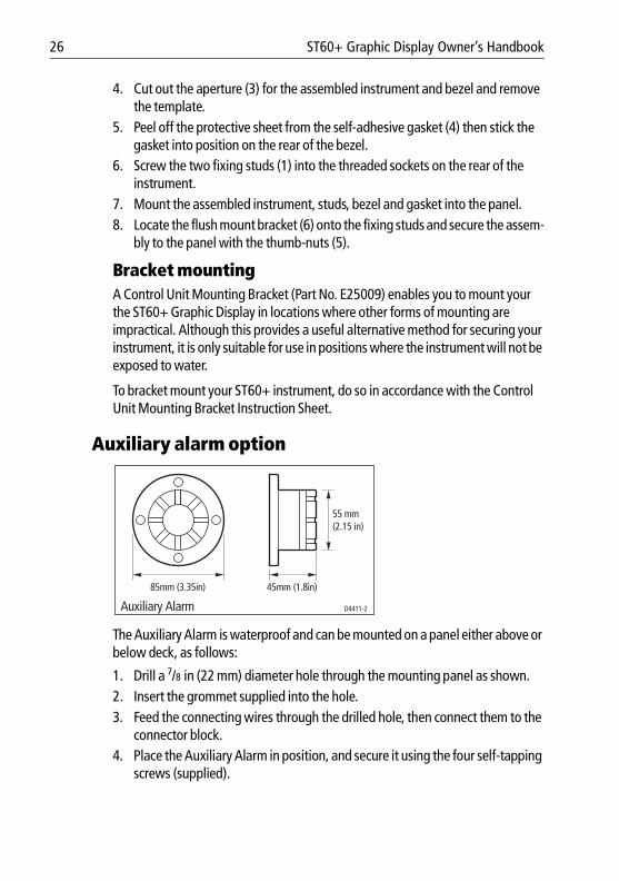
Auxiliary alarm option
The Auxiliary Alarm is waterproof and can be mounted on a panel either above or below deck, as follows:
1. Drill a 7/8 in (22 mm) diameter hole through the mounting panel as shown.2. Insert the grommet supplied into the hole.3. Feed the connecting wires through the drilled hole, then connect them to the
connector block. 4. Place the Auxiliary Alarm in position, and secure it using the four self-tapping
screws (supplied).
45mm (1.8in)85mm (3.35in)
D4411-2Auxiliary Alarm
55 mm(2.15 in)
Chapter 3: Installation 27
81268_2.book Page 27 Monday, December 5, 2005 9:44 AM
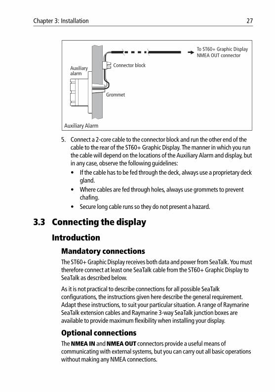
5. Connect a 2-core cable to the connector block and run the other end of the cable to the rear of the ST60+ Graphic Display. The manner in which you run the cable will depend on the locations of the Auxiliary Alarm and display, but in any case, observe the following guidelines:• If the cable has to be fed through the deck, always use a proprietary deck
gland.• Where cables are fed through holes, always use grommets to prevent
chafing.• Secure long cable runs so they do not present a hazard.
3.3 Connecting the display
Introduction
Mandatory connectionsThe ST60+ Graphic Display receives both data and power from SeaTalk. You must therefore connect at least one SeaTalk cable from the ST60+ Graphic Display to SeaTalk as described below.
As it is not practical to describe connections for all possible SeaTalk configurations, the instructions given here describe the general requirement. Adapt these instructions, to suit your particular situation. A range of Raymarine SeaTalk extension cables and Raymarine 3-way SeaTalk junction boxes are available to provide maximum flexibility when installing your display.
Optional connectionsThe NMEA IN and NMEA OUT connectors provide a useful means of communicating with external systems, but you can carry out all basic operations without making any NMEA connections.
Connector blockAuxiliaryalarm
Grommet
Auxiliary Alarm
To ST60+ Graphic Display NMEA OUT connector
28 ST60+ Graphic Display Owner’s Handbook
81268_2.book Page 28 Monday, December 5, 2005 9:44 AM
Connecting to SeaTalk
Power requirements
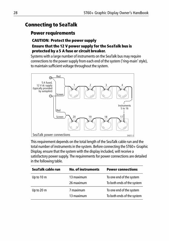
Systems with a large number of instruments on the SeaTalk bus may require connections to the power supply from each end of the system (‘ring-main’ style), to maintain sufficient voltage throughout the system.
This requirement depends on the total length of the SeaTalk cable run and the total number of instruments in the system. Before connecting the ST60+ Graphic Display, ensure that the system with the display included, will receive a satisfactory power supply. The requirements for power connections are detailed in the following table. :
CAUTION: Protect the power supplyEnsure that the 12 V power supply for the SeaTalk bus is protected by a 5 A fuse or circuit breaker.
SeaTalk cable run No. of instruments Power connections
Up to 10 m 13 maximum To one end of the system
26 maximum To both ends of the system
Up to 20 m 7 maximum To one end of the system
13 maximum To both ends of the system
D4311-1
5 A fused,12 V dc supply
(typically providedby autopilot)
Red
Screen
Red
Screen
1 2 3 4
Instruments5 to 16
17181920
SeaTalk power connections
Chapter 3: Installation 29
81268_2.book Page 29 Monday, December 5, 2005 9:44 AM
ProcedureConnect your ST60+ Graphic Display as follows:1. Ensure that:
• Power to the existing SeaTalk system is switched off.• The conditions described under Power requirements are fulfilled.
2. Plug the SeaTalk cable(s) from the rear of the display into a vacant SeaTalk connector on an adjacent instrument. You can either break an existing SeaTalk chain, or connect to the end of the SeaTalk bus.
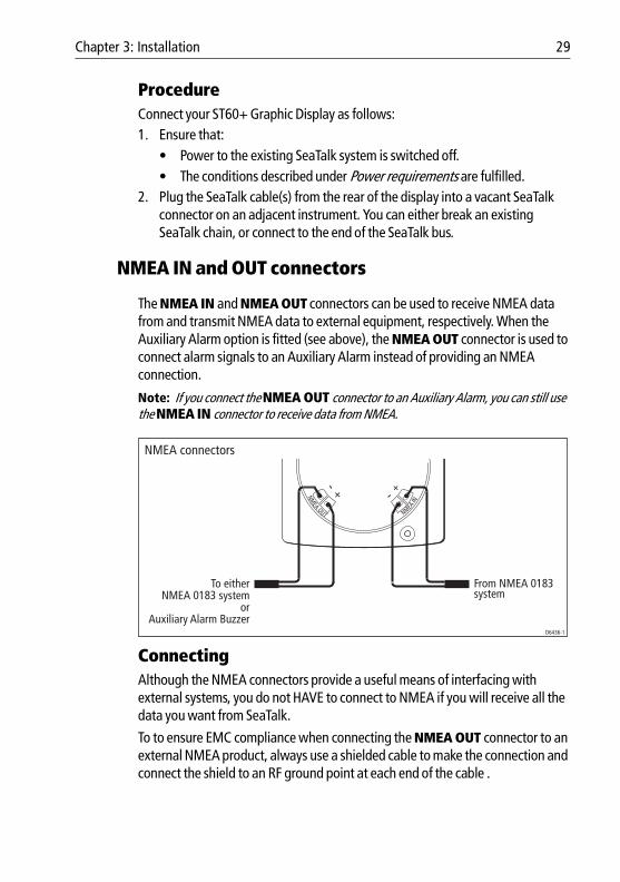
NMEA IN and OUT connectors
The NMEA IN and NMEA OUT connectors can be used to receive NMEA data from and transmit NMEA data to external equipment, respectively. When the Auxiliary Alarm option is fitted (see above), the NMEA OUT connector is used to connect alarm signals to an Auxiliary Alarm instead of providing an NMEA connection.
Note: If you connect the NMEA OUT connector to an Auxiliary Alarm, you can still use the NMEA IN connector to receive data from NMEA.
ConnectingAlthough the NMEA connectors provide a useful means of interfacing with external systems, you do not HAVE to connect to NMEA if you will receive all the data you want from SeaTalk.
To to ensure EMC compliance when connecting the NMEA OUT connector to an external NMEA product, always use a shielded cable to make the connection and connect the shield to an RF ground point at each end of the cable .
NMEA connectors
D6436-1
NMEAIN
NMEA OUT
To either NMEA 0183 system
orAuxiliary Alarm Buzzer
From NMEA 0183 system
30 ST60+ Graphic Display Owner’s Handbook
81268_2.book Page 30 Monday, December 5, 2005 9:44 AM
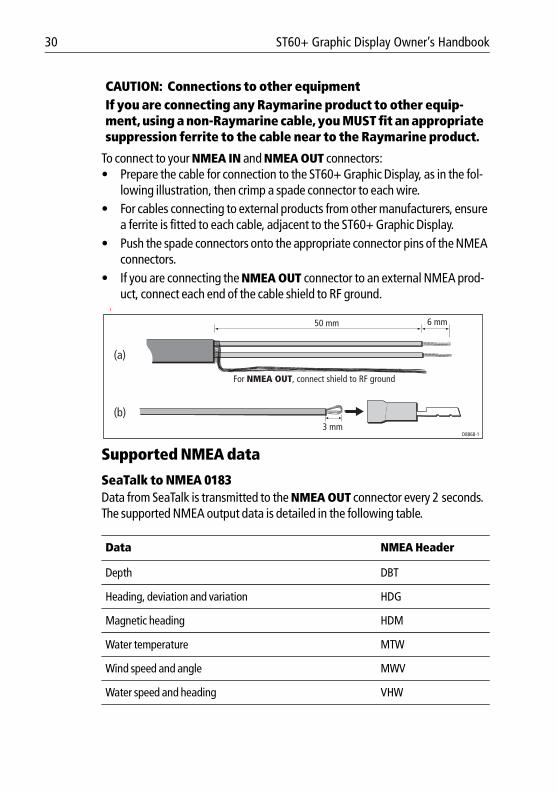
To connect to your NMEA IN and NMEA OUT connectors:• Prepare the cable for connection to the ST60+ Graphic Display, as in the fol-
lowing illustration, then crimp a spade connector to each wire.• For cables connecting to external products from other manufacturers, ensure
a ferrite is fitted to each cable, adjacent to the ST60+ Graphic Display.• Push the spade connectors onto the appropriate connector pins of the NMEA
connectors.• If you are connecting the NMEA OUT connector to an external NMEA prod-
uct, connect each end of the cable shield to RF ground. I
Supported NMEA data
SeaTalk to NMEA 0183Data from SeaTalk is transmitted to the NMEA OUT connector every 2 seconds. The supported NMEA output data is detailed in the following table.
CAUTION: Connections to other equipmentIf you are connecting any Raymarine product to other equip-ment, using a non-Raymarine cable, you MUST fit an appropriate suppression ferrite to the cable near to the Raymarine product.
Data NMEA Header
Depth DBT
Heading, deviation and variation HDG
Magnetic heading HDM
Water temperature MTW
Wind speed and angle MWV
Water speed and heading VHW
3 mm
6 mm50 mm
(a)
(b)
D8868-1
For NMEA OUT, connect shield to RF ground
Chapter 3: Installation 31
81268_2.book Page 31 Monday, December 5, 2005 9:44 AM
NMEA to SeaTalkWhen supported NMEA data is available at the NMEA IN connector, it is decoded and displayed by the ST60+ Graphic Display. The supported NMEA input data is detailed in the following table. :
3.4 Starting procedures
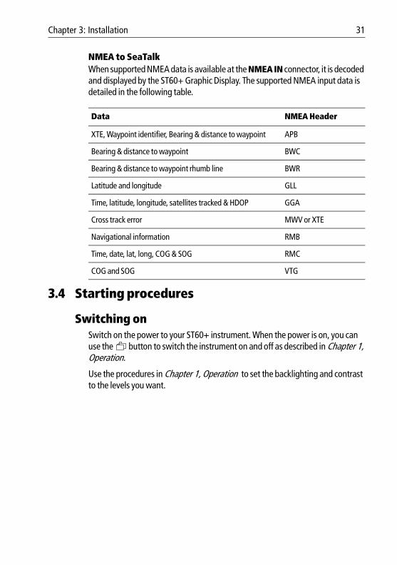
Switching onSwitch on the power to your ST60+ instrument. When the power is on, you can use the button to switch the instrument on and off as described in Chapter 1, Operation.
Use the procedures in Chapter 1, Operation to set the backlighting and contrast to the levels you want.
Data NMEA Header
XTE, Waypoint identifier, Bearing & distance to waypoint APB
Bearing & distance to waypoint BWC
Bearing & distance to waypoint rhumb line BWR
Latitude and longitude GLL
Time, latitude, longitude, satellites tracked & HDOP GGA
Cross track error MWV or XTE
Navigational information RMB
Time, date, lat, long, COG & SOG RMC
COG and SOG VTG
32 ST60+ Graphic Display Owner’s Handbook
81268_2.book Page 32 Monday, December 5, 2005 9:44 AM
.
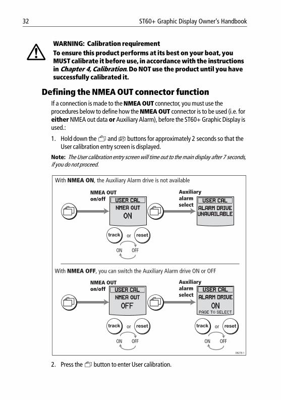
Defining the NMEA OUT connector functionIf a connection is made to the NMEA OUT connector, you must use the procedures below to define how the NMEA OUT connector is to be used (i.e. for either NMEA out data or Auxiliary Alarm), before the ST60+ Graphic Display is used.:
1. Hold down the and buttons for approximately 2 seconds so that the User calibration entry screen is displayed.
Note: The User calibration entry screen will time out to the main display after 7 seconds, if you do not proceed.
2. Press the button to enter User calibration.
WARNING: Calibration requirementTo ensure this product performs at its best on your boat, you MUST calibrate it before use, in accordance with the instructions in Chapter 4, Calibration. Do NOT use the product until you have successfully calibrated it.
ortrack reset
ON OFF
With NMEA ON, the Auxiliary Alarm drive is not available
ortrack reset
ON OFF
ortrack reset
ON OFF
With NMEA OFF, you can switch the Auxiliary Alarm drive ON or OFF
NMEA OUT on/off
Auxiliary alarm select
NMEA OUT on/off
Auxiliary alarm select
D8270-1
Chapter 3: Installation 33
81268_2.book Page 33 Monday, December 5, 2005 9:44 AM
3. Use the button to go to the NMEA OUT on/off screen.4. Use the track or reset button to switch the NMEA OUT function ON or
OFF , as required. If you set:• NMEA ON, then the Auxiliary Alarm output is disabled and the Auxiliary
Alarm Select screen (the next screen) shows ALARM DRIVE UNAVAILABLE .
• NMEA OFF, then the Auxiliary Alarm output is available, and you can switch the Auxiliary Alarm drive ON or OFF at the Auxiliary Alarm Select screen, using the track or reset buttons.
5. When you have set NMEA OUT and ALARM DRIVE as required, hold down the and buttons for approximately 2 seconds to return to nor-mal operation.
EMC conformanceAlways check the installation before going to sea to make sure that it is not affected by radio transmissions, engine starting etc.

34 ST60+ Graphic Display Owner’s Handbook
81268_2.book Page 34 Monday, December 5, 2005 9:44 AM
35
81268_2.book Page 35 Monday, December 5, 2005 9:44 AM
Chapter 4: Calibration
4.1 IntroductionUse this chapter to set up and check the ST60+ Graphic Display, before it is used operationally. Instructions are given to enable you to:• Define the function of the NMEA OUT connector (see Chapter 1, System
Connections ).• Carry out Dealer calibration.• Check basic operation.
4.2 User calibrationA User calibration facility enables you to:• Set the Favorite page rollover period, or switch the rollover off.• Switch chapter titles on or off.• Set whether headings are displayed in true or magnetic form.• Set the voltage at which a battery alarm will occur.• Enable/disable individual local alarms.• Set the date format.• Set the time format.• Set the instrument time to local time.• Select the units in which NMEA data are displayed.• Select the function of the display NMEA OUT connector. This is either
• A remote alarm output for the Auxiliary Alarm (NMEA OFF).or
• NMEA output signals.• Enable/disable individual remote alarms. • Enable/disable the pilot pop up display.• Configure the instrument to display specific pages.
ProcedureTo carry out the required setup procedure:
1. Hold down the and buttons for approximately 2 seconds so that the User calibration entry screen is displayed.
Note: The User calibration entry screen will time out to the main display after 7 seconds.
36 ST60+ Graphic Display Owner’s Handbook
81268_2.book Page 36 Monday, December 5, 2005 9:44 AM
2. Press the button to enter User calibration.
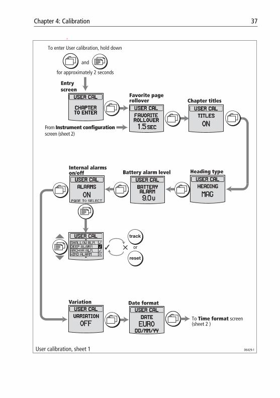
3. Referring to the User calibration diagram below, use the button to cycle to the required screen, then set the required values as described below.
Favorite page rolloverUse the track or reset button to set the required Favorite page rollover period, from 0.5 SEC to 20 SEC. Press the track button to reduce the rollover period and the reset button to increase it.
If you want to be able to select Favorite pages manually as for other chapters, use the track button to reduce the value of the rollover until OFF is displayed.
Chapter titlesUse the track and reset buttons to select either:
• ON, so that each chapter title is briefly displayed when the chapter is selected during normal operation,or
• OFF, if you do not want chapter titles to be displayed.
Heading typeUse this to define how heading values are displayed. Use the track and reset buttons to select either magnetic (MAG) or true (TRUE). If a variation value is not available on SeaTalk, then MAG is selected permanently.
Battery alarm thresholdUse the track and reset buttons to set the required voltage alarm threshold, in the range 9 V to 14 V. Press the track button to reduce the level and the reset button to increase it.
The recommended value is 10.5 V.
If you want to switch off the battery alarm, Press the track button to reduce the level until OFF is displayed.
Chapter 4: Calibration 37
81268_2.book Page 37 Monday, December 5, 2005 9:44 AM
p
From Instrument configuration screen (sheet 2)
User calibration, sheet 1 D6429-1
Chapter titles
Heading typeBattery alarm levelInternal alarms on/off
To enter User calibration, hold down
and
for approximately 2 seconds
Entryscreen
Date formatVariation
or✓ ✕
track
reset
Favorite page rollover
To Time format screen (sheet 2 )
38 ST60+ Graphic Display Owner’s Handbook
81268_2.book Page 38 Monday, December 5, 2005 9:44 AM
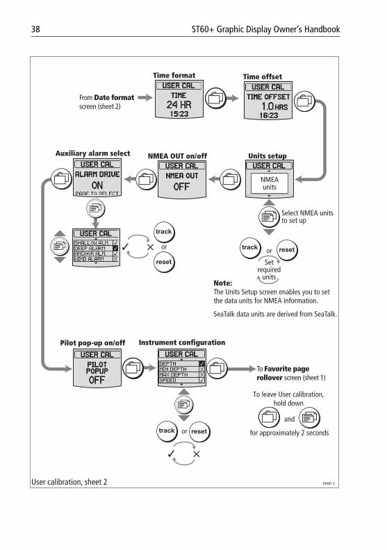
Units setup
Time format
Auxiliary alarm select
Pilot pop-up on/off Instrument configuration
NMEA OUT on/off
Time offset
ortrack reset
Set required
units
Select NMEA units to set up
From Date format screen (sheet 2)
or
track
reset
✓ ✕
ortrack reset
✓ ✕
To Favorite page rollover screen (sheet 1)
User calibration, sheet 2 D6481-2
To leave User calibration, hold down
and
for approximately 2 seconds
Note:The Units Setup screen enables you to set the data units for NMEA information.
SeaTalk data units are derived from SeaTalk.
NMEA units
Chapter 4: Calibration 39
81268_2.book Page 39 Monday, December 5, 2005 9:44 AM
Internal alarms on/offUse the track or reset button to set the internal ALARMS OFF if you do not want the ST60+ Graphic Display to give alarm indications. Otherwise, set ALARMS ON .
If you have set the ALARMS ON , set the individual internal alarms as follows:
1. Press the button to display the list of alarms. The first alarm is highlighted, to indicate you can adjust it.
2. Use the track or reset button to either enable (✓) or disable (✘) the high-lighted alarm.
3. Use the button to move the highlight to each alarm in turn, and either enable or disable it, as described in step 2.
Note: External alarms (see Auxiliary Alarm select below) will occur, irrespective of the in-ternal alarm settings.
VariationIf an external magnetic variation value is available from SeaTalk or NMEA, this will be used by the ST60+ Graphic Display.
If an external variation input is not available, use the button to set VARIATION ON , then use the track and reset buttons to set the correct magnetic variation value.
If you do not want to display the variation value, use the button to set VARIATION OFF .
Date formatUse the track or reset button to select the required date format. Either United States (MM/DD/YY) or European (DD/MM/YY).
Time formatUse the track or reset button to select either 12-hour or 24-hour time format.
Time offsetUse the track or reset button to apply an appropriate offset to set your system time to local time. You can set any offset in the range -12 hours to +12 hours, in half-hour increments. The time with the offset applied is shown at the bottom of the screen.
40 ST60+ Graphic Display Owner’s Handbook
81268_2.book Page 40 Monday, December 5, 2005 9:44 AM
Units setupThe units in which SeaTalk data is displayed, are determined by the respective master instruments. However, as the ST60+ Graphic Display can also display NMEA data, the Units setup screen enables you to set the units for this data.
Setting unitsWith the Units setup screen displayed, use the button to move to each data type in turn and for each, use the track or reset button to select the required unit.
NMEA OUT on/offThe NMEA OUT on/off screen enables you to set which function the NMEA OUT connector provides. This is either:• NMEA data out.
or• Alarm signals for the Auxiliary Alarm.
If want to output NMEA data, use the track or reset button to select NMEA OUT ON . If you want to output alarm signals to the Auxiliary Alarm, select NMEA OUT OFF .
Auxiliary Alarm selectUse the ALARM DRIVE screen to determine which alarms you want to sound at the Auxiliary Alarm.
Note: The NMEA OUT function must be OFF, to enable the Auxiliary Alarm to be used.
Use the track or reset button to set ALARM DRIVE OFF , if you do not want any alarms to sound at the Auxiliary Alarm. Otherwise, set ALARM DRIVE ON
If you have set ALARM DRIVE ON , use the button to move to each alarm in turn and for each, use the track or reset button to either enable (✓) or disable (✘) the alarm.
Pilot pop-upUse the track or reset button to set the PILOT POPUP either ON or OFF, as required.
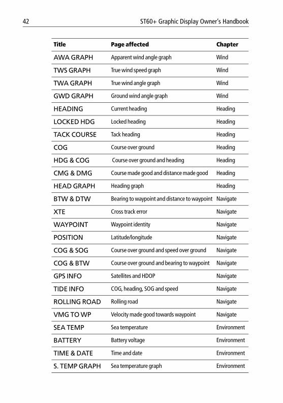
Instrument configurationYou can streamline the operation of the instrument by defining which pages are available for display on a day-to-day basis, and switching off pages you do not wish to see.
Chapter 4: Calibration 41
81268_2.book Page 41 Monday, December 5, 2005 9:44 AM
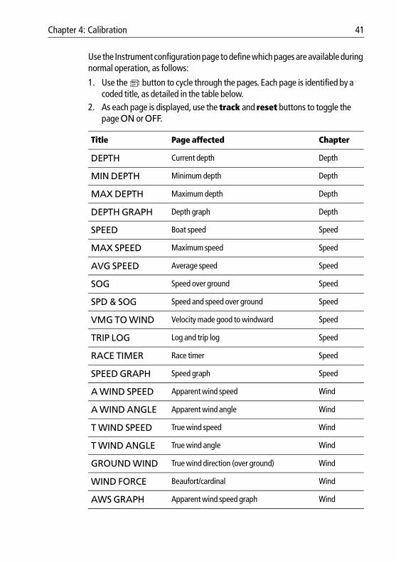
Use the Instrument configuration page to define which pages are available during normal operation, as follows:
1. Use the button to cycle through the pages. Each page is identified by a coded title, as detailed in the table below.
2. As each page is displayed, use the track and reset buttons to toggle the page ON or OFF.
.
Title Page affected Chapter
DEPTH Current depth Depth
MIN DEPTH Minimum depth Depth
MAX DEPTH Maximum depth Depth
DEPTH GRAPH Depth graph Depth
SPEED Boat speed Speed
MAX SPEED Maximum speed Speed
AVG SPEED Average speed Speed
SOG Speed over ground Speed
SPD & SOG Speed and speed over ground Speed
VMG TO WIND Velocity made good to windward Speed
TRIP LOG Log and trip log Speed
RACE TIMER Race timer Speed
SPEED GRAPH Speed graph Speed
A WIND SPEED Apparent wind speed Wind
A WIND ANGLE Apparent wind angle Wind
T WIND SPEED True wind speed Wind
T WIND ANGLE True wind angle Wind
GROUND WIND True wind direction (over ground) Wind
WIND FORCE Beaufort/cardinal Wind
AWS GRAPH Apparent wind speed graph Wind
42 ST60+ Graphic Display Owner’s Handbook
81268_2.book Page 42 Monday, December 5, 2005 9:44 AM
AWA GRAPH Apparent wind angle graph Wind
TWS GRAPH True wind speed graph Wind
TWA GRAPH True wind angle graph Wind
GWD GRAPH Ground wind angle graph Wind
HEADING Current heading Heading
LOCKED HDG Locked heading Heading
TACK COURSE Tack heading Heading
COG Course over ground Heading
HDG & COG Course over ground and heading Heading
CMG & DMG Course made good and distance made good Heading
HEAD GRAPH Heading graph Heading
BTW & DTW Bearing to waypoint and distance to waypoint Navigate
XTE Cross track error Navigate
WAYPOINT Waypoint identity Navigate
POSITION Latitude/longitude Navigate
COG & SOG Course over ground and speed over ground Navigate
COG & BTW Course over ground and bearing to waypoint Navigate
GPS INFO Satellites and HDOP Navigate
TIDE INFO COG, heading, SOG and speed Navigate
ROLLING ROAD Rolling road Navigate
VMG TO WP Velocity made good towards waypoint Navigate
SEA TEMP Sea temperature Environment
BATTERY Battery voltage Environment
TIME & DATE Time and date Environment
S. TEMP GRAPH Sea temperature graph Environment
Title Page affected Chapter
Chapter 4: Calibration 43
81268_2.book Page 43 Monday, December 5, 2005 9:44 AM
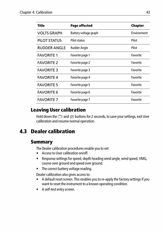
Leaving User calibrationHold down the and buttons for 2 seconds, to save your settings, exit User calibration and resume normal operation.
4.3 Dealer calibration
SummaryThe Dealer calibration procedures enable you to set:• Access to User calibration on/off. • Response settings for speed, depth heading wind angle, wind speed, VMG,
course over ground and speed over ground. • The correct battery voltage reading.
Dealer calibration also gives access to:• A default reset screen. This enables you to re-apply the factory settings if you
want to reset the instrument to a known operating condition.• A self-test entry screen.
VOLTS GRAPH Battery voltage graph Environment
PILOT STATUS Pilot status Pilot
RUDDER ANGLE Rudder Angle Pilot
FAVORITE 1 Favorite page 1 Favorite
FAVORITE 2 Favorite page 2 Favorite
FAVORITE 3 Favorite page 3 Favorite
FAVORITE 4 Favorite page 4 Favorite
FAVORITE 5 Favorite page 5 Favorite
FAVORITE 6 Favorite page 6 Favorite
FAVORITE 7 Favorite page 7 Favorite
Title Page affected Chapter
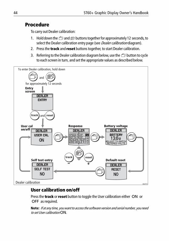
44 ST60+ Graphic Display Owner’s Handbook
81268_2.book Page 44 Monday, December 5, 2005 9:44 AM
ProcedureTo carry out Dealer calibration:
1. Hold down the and buttons together for approximately 12 seconds, to select the Dealer calibration entry page (see Dealer calibration diagram).
2. Press the track and reset buttons together, to start Dealer calibration.
3. Referring to the Dealer calibration diagram below, use the button to cycle to each screen in turn, and set the appropriate values as described below.
User calibration on/offPress the track or reset button to toggle the User calibration either ON or OFF as required.
Note: If at any time, you want to access the software version and serial number, you need to set User calibration ON.
D6479-1
for approximately 12 seconds
Dealer calibration
To enter Dealer calibration, hold down
and
User cal on/off
Response Battery voltage
Default resetSelf test entry
Entryscreen
track reset
track resetand
Chapter 4: Calibration 45
81268_2.book Page 45 Monday, December 5, 2005 9:44 AM
Response settingsThe response values determine the sensitivity of the display to data changes. You can set each response value from 1 to 15. A low number provides a smooth response and a high number a much livelier response.
Use the button to select the response you want to set, then use the track (decrement) and reset (increment) buttons to set the required value.
You can set responses for the following data:• Speed (SPEED RESP.)• Depth (DEPTH RESP.)• Heading (HEADING RESP.)• Wind angle (WIND ANGLE R.)• Wind speed (WIND SPEED R.)• Cross track error (XTE RESP.)
Battery voltageUse the BATTERY screen to set the voltage reading at the ST60+ Graphic Display to be the same as the actual supply voltage from the boat’s electrical system.
To set the voltage reading at the ST60+ Graphic Display:1. With the BATTERY screen displayed, measure the 12 V supply voltage at
the battery.2. At the ST60+ Graphic Display, use the track or reset button to set the dis-
played voltage to the same value as the measured voltage.
Default resetYou can use this screen to reset the operating parameters to the factory default values. Use the track and reset buttons to make the required selection.
Note that the selection you make at this screen will be applied when you exit the screen, so be sure you make the correct selection.
To retain the current values, ensure that the display shows NO.
WARNING: HIGH VOLTAGE HAZARDHigh voltages can cause death or serious injury. Always take appropriate precautions when working with electricity. Before accessing the electrical system, ensure you know the location of high voltage points and stay well clear of them.
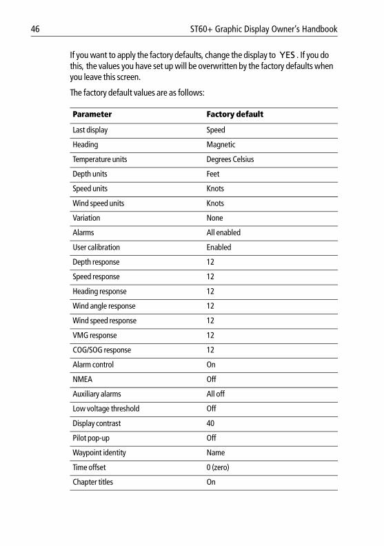
46 ST60+ Graphic Display Owner’s Handbook
81268_2.book Page 46 Monday, December 5, 2005 9:44 AM
If you want to apply the factory defaults, change the display to YES . If you do this, the values you have set up will be overwritten by the factory defaults when you leave this screen.
The factory default values are as follows:
Parameter Factory default
Last display Speed
Heading Magnetic
Temperature units Degrees Celsius
Depth units Feet
Speed units Knots
Wind speed units Knots
Variation None
Alarms All enabled
User calibration Enabled
Depth response 12
Speed response 12
Heading response 12
Wind angle response 12
Wind speed response 12
VMG response 12
COG/SOG response 12
Alarm control On
NMEA Off
Auxiliary alarms All off
Low voltage threshold Off
Display contrast 40
Pilot pop-up Off
Waypoint identity Name
Time offset 0 (zero)
Chapter titles On
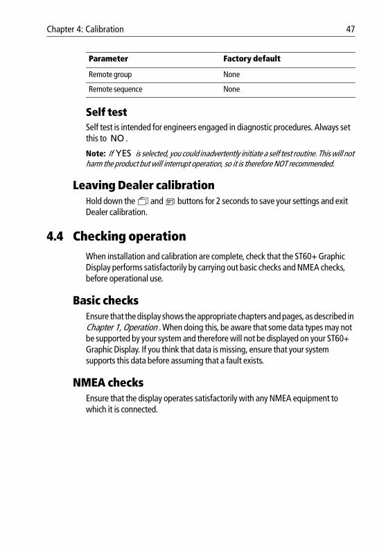
Chapter 4: Calibration 47
81268_2.book Page 47 Monday, December 5, 2005 9:44 AM
Self testSelf test is intended for engineers engaged in diagnostic procedures. Always set this to NO .
Note: If YES is selected, you could inadvertently initiate a self test routine. This will not harm the product but will interrupt operation, so it is therefore NOT recommended.
Leaving Dealer calibrationHold down the and buttons for 2 seconds to save your settings and exit Dealer calibration.
4.4 Checking operationWhen installation and calibration are complete, check that the ST60+ Graphic Display performs satisfactorily by carrying out basic checks and NMEA checks, before operational use.
Basic checksEnsure that the display shows the appropriate chapters and pages, as described in Chapter 1, Operation . When doing this, be aware that some data types may not be supported by your system and therefore will not be displayed on your ST60+ Graphic Display. If you think that data is missing, ensure that your system supports this data before assuming that a fault exists.
NMEA checksEnsure that the display operates satisfactorily with any NMEA equipment to which it is connected.
Remote group None
Remote sequence None
Parameter Factory default

48 ST60+ Graphic Display Owner’s Handbook
81268_2.book Page 48 Monday, December 5, 2005 9:44 AM
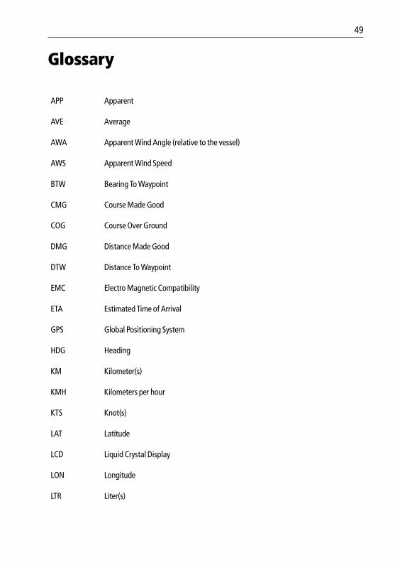
49
81268_2.book Page 49 Monday, December 5, 2005 9:44 AM
Glossary
APP Apparent
AVE Average
AWA Apparent Wind Angle (relative to the vessel)
AWS Apparent Wind Speed
BTW Bearing To Waypoint
CMG Course Made Good
COG Course Over Ground
DMG Distance Made Good
DTW Distance To Waypoint
EMC Electro Magnetic Compatibility
ETA Estimated Time of Arrival
GPS Global Positioning System
HDG Heading
KM Kilometer(s)
KMH Kilometers per hour
KTS Knot(s)
LAT Latitude
LCD Liquid Crystal Display
LON Longitude
LTR Liter(s)
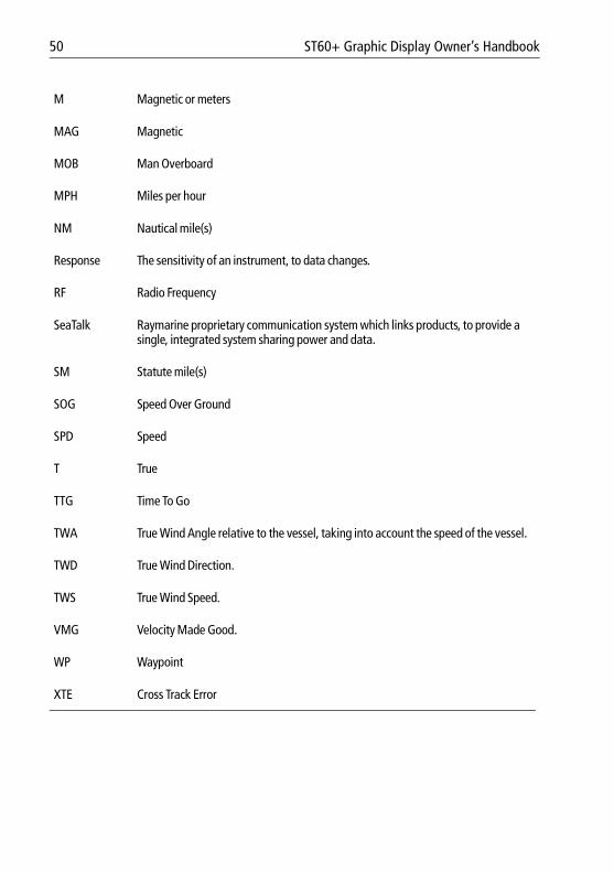
50 ST60+ Graphic Display Owner’s Handbook
81268_2.book Page 50 Monday, December 5, 2005 9:44 AM
M Magnetic or meters
MAG Magnetic
MOB Man Overboard
MPH Miles per hour
NM Nautical mile(s)
Response The sensitivity of an instrument, to data changes.
RF Radio Frequency
SeaTalk Raymarine proprietary communication system which links products, to provide a single, integrated system sharing power and data.
SM Statute mile(s)
SOG Speed Over Ground
SPD Speed
T True
TTG Time To Go
TWA True Wind Angle relative to the vessel, taking into account the speed of the vessel.
TWD True Wind Direction.
TWS True Wind Speed.
VMG Velocity Made Good.
WP Waypoint
XTE Cross Track Error
51
81268_2.book Page 51 Monday, December 5, 2005 9:44 AM
IndexAAlarms
Auxiliary Alarmsetup, 40
external, 12internal, 12
setup, 39silencing, 12
Autopilot pages, 9Autopilot pop-up setup, 40Autopilot status, 11Auxiliary Alarm, 12
setup, 40Auxiliary Alarm connections, 29
BBacklighting adjustment, 13Battery alarm setup, 36
CCalibration requirement, 31Changing timescales on graphs, 4Chapter titles, 3
switching on/off, 36Chapters & pages
Autopilot, 9Depth, 5enable/disable pages, 40Environment, 9Heading, 7Navigate, 8Speed, 6Wind, 6
Checking operation, 47Cleaning, 15Clock setup, 39Condensation, 15Connections
Auxiliary Alarm, 29mandatory, 27NMEA, 29optional, 27
Contrast adjustment, 14Customizing the display, 35
Auxiliary Alarm, 40
chapter titles, 36clock, 39date format, 39enable/disable pages, 40Favorite pages, 36internal alarms, 39NMEA OUT function, 40pilot pop-up, 40selecting heading type, 36setting battery alarm, 36time format, 39units, 40variation, 39
DData units setup, 40Date format setup, 39Dealer calibration
default reset, 45enable/disable User cal, 44setting responses, 45setting voltage reading, 45
Default settings, 45Depth pages, 5Display setup, 35Disposing of the product, iiEEMC information, i, 20, 33Environment pages, 9FFactory defaults, 45Favorite pages
setting up displayed data, 10setting up the rollover, 36
GGraphs, 4HHeading pages, 7Heading type
selecting magnetic or true, 36Help lines, 17
52 ST60+ Graphic Display Owner’s Handbook
81268_2.book Page 52 Monday, December 5, 2005 9:44 AM
IInitial checks, 47Installing
instrumentbracket mounting, 26flush mounting, 23power supply connections, 28requirements, 19signal connections, 29surface mounting, 22
planning, 19Instrument mounting options, viii
MMounting options (instrument), viii
NNavigate pages, 8NMEA connections, 29NMEA OUT
setting function, 32uses, 29
NMEA OUT setup, 40NMEA supported data, 30
PParts supplied, ix–xProduct disposal, iiRRemote control, viiiReset defaults, 45Rolling road, 4SSafety, 15
calibration requirement, 31electrical, igeneral, inavigation, i
SeaTalk overview, viiSetting up
Auxiliary Alarm, 40chapter titles, 36clock, 39date format, 39display responses, 45enable/disable pages, 40Favorite pages, 36
internal alarms, 39NMEA OUT function, 32, 40pilot pop-up, 40selecting heading type, 36setting battery alarm, 36time format, 39units, 40User calibration on/off, 44variation, 39voltage reading, 45
Silencing alarms, 12Site requirements
instrument, 19Software version, 17Speed pages, 6Switching on/off, 1, 31
TTechnical support, 16Time format setup, 39Troubleshooting, 16
UUser calibration, 35
Auxiliary Alarm setup, 40chapter titles, 36date format, 39enable/disable, 44enable/disable pages, 40Favorite pages, 36internal alarms, 39pilot pop-up, 40selecting heading type, 36setting battery alarm, 36setting clock, 39setting NMEA OUT function, 40setting units, 40time format, 39variation, 39
VVariation, 39
WWind pages, 6
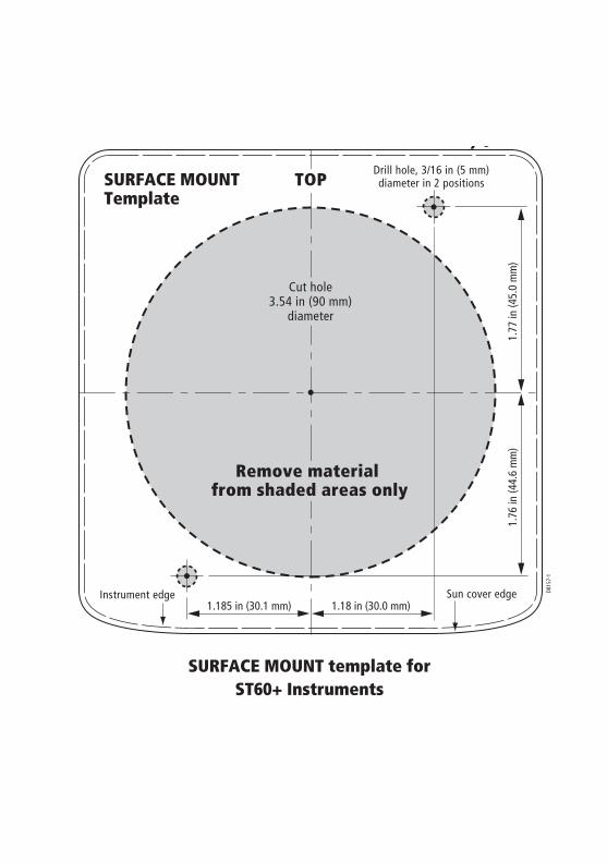
SURFACE MOUNT template for ST60+ Instruments
1.185 in (30.1 mm) 1.18 in (30.0 mm)
SURFACE MOUNTTemplate
Sun cover edge D815
7-1
Cut hole3.54 in (90 mm)
diameter
Drill hole, 3/16 in (5 mm)diameter in 2 positions
1.77
in (4
5.0
mm
)1.
76 in
(44.
6 m
m)
Remove material from shaded areas only
TOP
Instrument edge
81268_2.book Page 53 Monday, December 5, 2005 9:44 AM

81268_2.book Page 54 Monday, December 5, 2005 9:44 AM
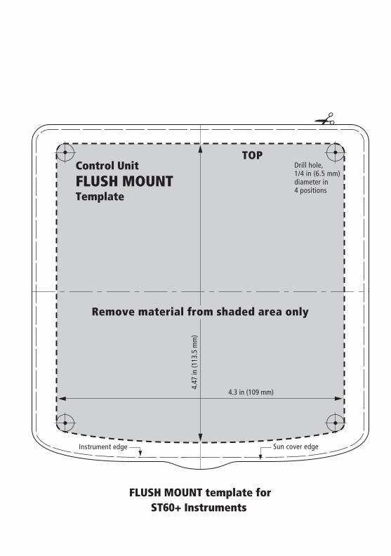
81268_2.book Page 55 Monday, December 5, 2005 9:44 AM
4.3 in (109 mm)
4.47
in (1
13.5
mm
)
Sun cover edgeInstrument edge
Remove material from shaded area only
Drill hole,1/4 in (6.5 mm) diameter in4 positions
TOPControl UnitFLUSH MOUNTTemplate
FLUSH MOUNT template forST60+ Instruments

81268_2.book Page 56 Monday, December 5, 2005 9:44 AM