Embed Size (px)
Citation preview

Engineering the Next Generation of
High-Performance Seals
industry focus steel & Aluminum
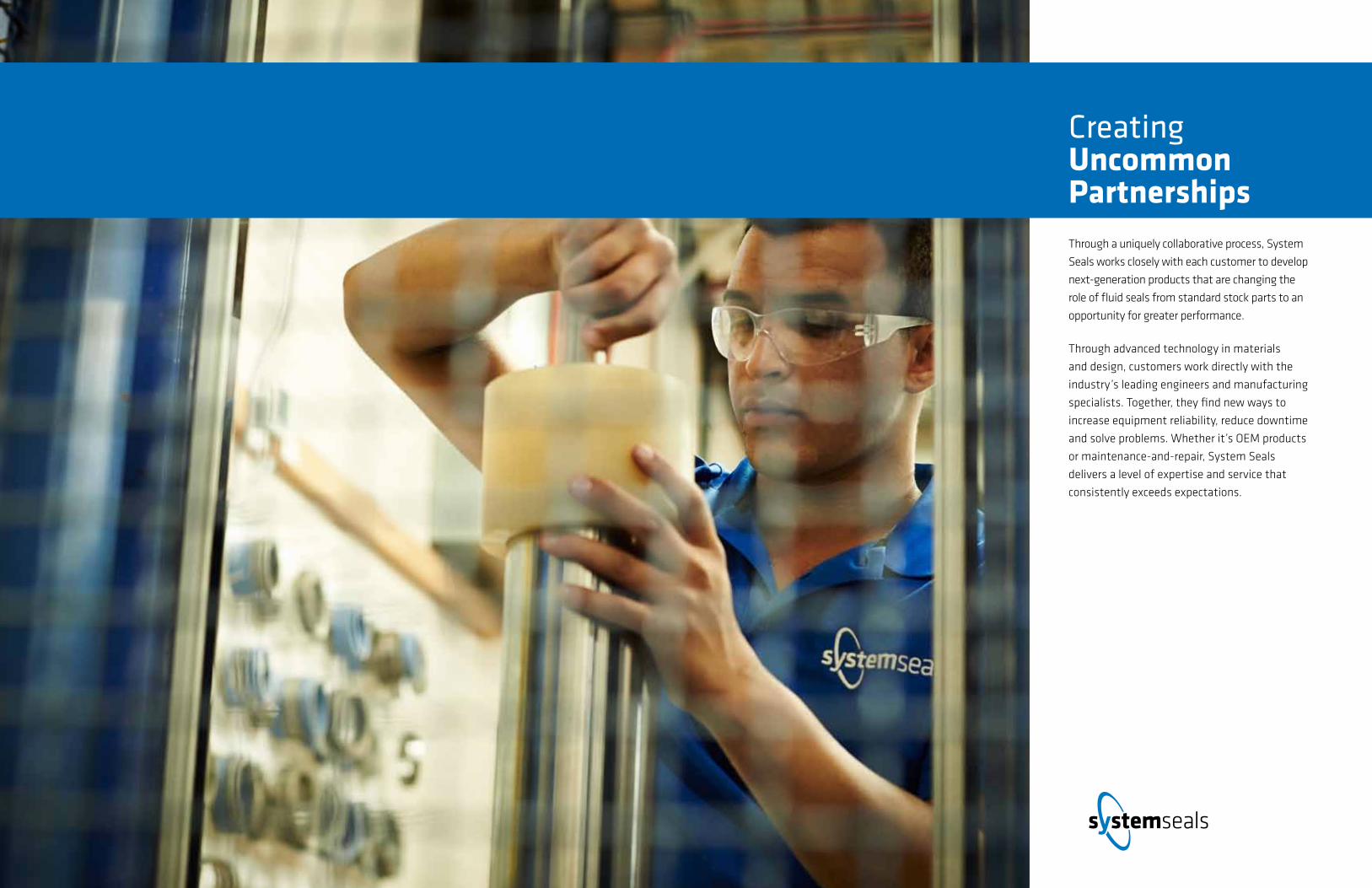
Creating Uncommon Partnerships Through a uniquely collaborative process, System
Seals works closely with each customer to develop
next-generation products that are changing the
role of fluid seals from standard stock parts to an
opportunity for greater performance.
Through advanced technology in materials
and design, customers work directly with the
industry’s leading engineers and manufacturing
specialists. Together, they find new ways to
increase equipment reliability, reduce downtime
and solve problems. Whether it’s OEM products
or maintenance-and-repair, System Seals
delivers a level of expertise and service that
consistently exceeds expectations.
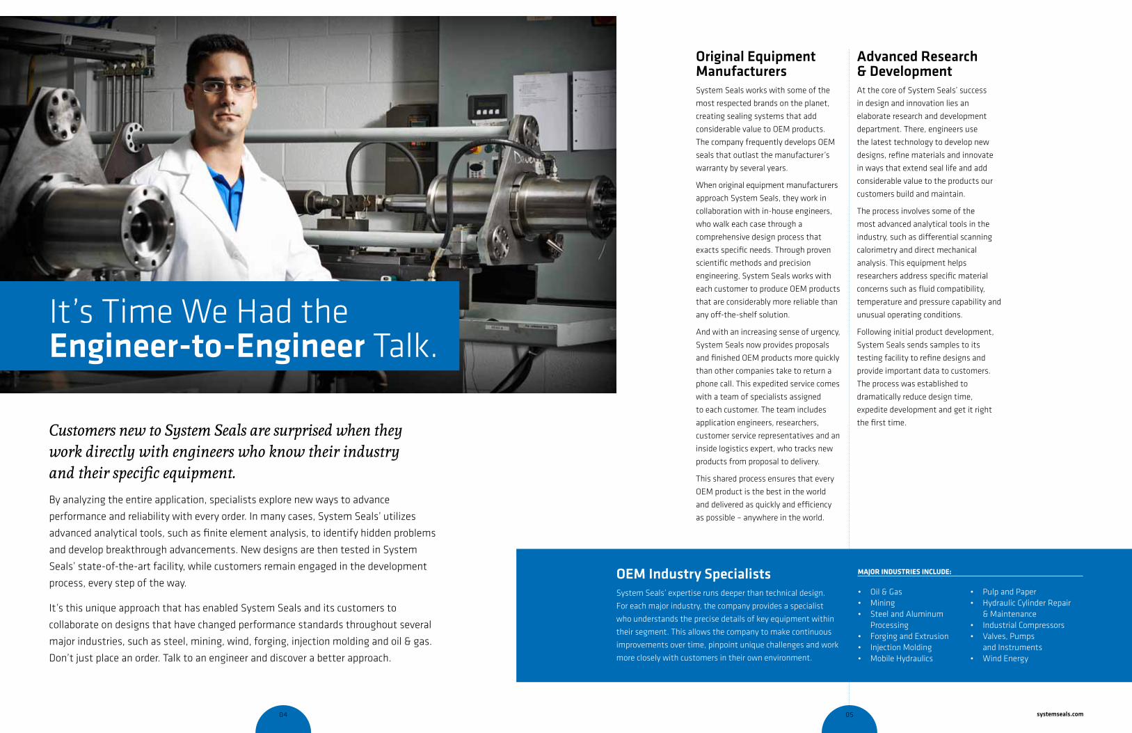
It’s Time We Had the engineer-to-engineer Talk.
Advanced Research & Development At the core of System Seals’ success
in design and innovation lies an
elaborate research and development
department. There, engineers use
the latest technology to develop new
designs, refine materials and innovate
in ways that extend seal life and add
considerable value to the products our
customers build and maintain.
The process involves some of the
most advanced analytical tools in the
industry, such as differential scanning
calorimetry and direct mechanical
analysis. This equipment helps
researchers address specific material
concerns such as fluid compatibility,
temperature and pressure capability and
unusual operating conditions.
Following initial product development,
System Seals sends samples to its
testing facility to refine designs and
provide important data to customers.
The process was established to
dramatically reduce design time,
expedite development and get it right
the first time.
Original equipment manufacturersSystem Seals works with some of the
most respected brands on the planet,
creating sealing systems that add
considerable value to OEM products.
The company frequently develops OEM
seals that outlast the manufacturer’s
warranty by several years.
When original equipment manufacturers
approach System Seals, they work in
collaboration with in-house engineers,
who walk each case through a
comprehensive design process that
exacts specific needs. Through proven
scientific methods and precision
engineering, System Seals works with
each customer to produce OEM products
that are considerably more reliable than
any off-the-shelf solution.
And with an increasing sense of urgency,
System Seals now provides proposals
and finished OEM products more quickly
than other companies take to return a
phone call. This expedited service comes
with a team of specialists assigned
to each customer. The team includes
application engineers, researchers,
customer service representatives and an
inside logistics expert, who tracks new
products from proposal to delivery.
This shared process ensures that every
OEM product is the best in the world
and delivered as quickly and efficiency
as possible – anywhere in the world.
Customers new to System Seals are surprised when they work directly with engineers who know their industry and their specific equipment. By analyzing the entire application, specialists explore new ways to advance
performance and reliability with every order. In many cases, System Seals’ utilizes
advanced analytical tools, such as finite element analysis, to identify hidden problems
and develop breakthrough advancements. New designs are then tested in System
Seals’ state-of-the-art facility, while customers remain engaged in the development
process, every step of the way.
It’s this unique approach that has enabled System Seals and its customers to
collaborate on designs that have changed performance standards throughout several
major industries, such as steel, mining, wind, forging, injection molding and oil & gas.
Don’t just place an order. Talk to an engineer and discover a better approach.
Oem industry specialistsSystem Seals’ expertise runs deeper than technical design.
For each major industry, the company provides a specialist
who understands the precise details of key equipment within
their segment. This allows the company to make continuous
improvements over time, pinpoint unique challenges and work
more closely with customers in their own environment.
• Oil & Gas• Mining• Steel and Aluminum
Processing• Forging and Extrusion• Injection Molding• Mobile Hydraulics
• Pulp and Paper• Hydraulic Cylinder Repair
& Maintenance• Industrial Compressors• Valves, Pumps
and Instruments• Wind Energy
Major iNdUstries iNclUde:
04 05 systemseals.com
maintenance & RepairToo often, equipment operators settle
for routine leaks and the expensive
habit of relying on inferior stock seals.
System Seals works closely with
maintenance-and-repair customers to
solve problems, find new and better
ways to stop leaks, reduce downtime
and significantly increase reliability.
In many cases, System Seals has
custom designed maintenance-and-
repair seals that have saved customers
millions of dollars in lost productivity.
In heavy duty applications, such as
forging and steel mills, the company has
dramatically extended time between
scheduled maintenance by improved
designs specific to their equipment.
Speed is critical. That’s why System
Seals manufactures and delivers
customized products more quickly than
any other seal producer. And our highly
experienced engineers and industry
specialists work directly with equipment
operators to ensure their products are
performing at their best. This includes
installation help, technical support,
failure analysis and troubleshooting
long after delivery.
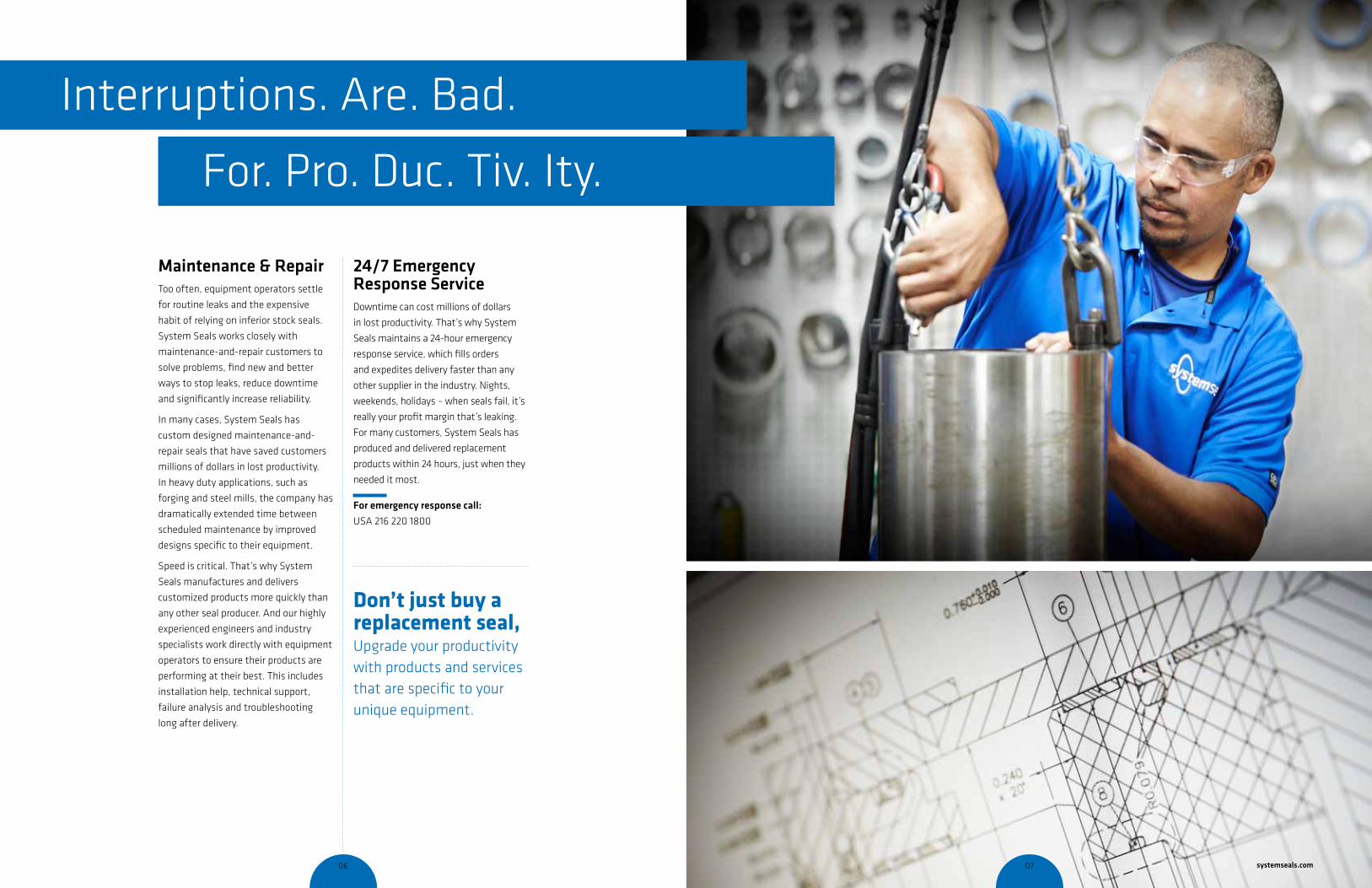
24/7 emergency Response serviceDowntime can cost millions of dollars
in lost productivity. That’s why System
Seals maintains a 24-hour emergency
response service, which fills orders
and expedites delivery faster than any
other supplier in the industry. Nights,
weekends, holidays – when seals fail, it’s
really your profit margin that’s leaking.
For many customers, System Seals has
produced and delivered replacement
products within 24 hours, just when they
needed it most.
For emergency response call:
USA 216 220 1800
Interruptions. Are. Bad.
For. Pro. Duc. Tiv. Ity.
don’t just buy a replacement seal, Upgrade your productivity with products and services that are specific to your unique equipment.
06 07 systemseals.com
Collaborative innovations System Seals’ success in steel and
aluminum processing stems from a
uniquely collaborative process with
each customer. Our design engineers
and metals specialists work directly
with OEMS and mill operators to
address needs specific to their
applications. Together, they find new
ways to innovate, solve problems and
increase reliability.
This approach has enabled the creation
of several groundbreaking products
throughout the steel industry. It was
made possible through System Seals’
intuitive commitment to research and
development, an extensive on-site
testing facility and a team of the
industry’s most ambitious engineers.
Capital Project Consulting System Seals provides a comprehensive
consulting service at no charge to steel
and aluminum mills during capital
projects and equipment rebuilds. These
projects are ideal opportunities to
review entire seal systems and gain a
better understanding for how they work
together within specific equipment.
During these engagements, System
Seals reviews existing seals, analyzes
equipment wear and incorporates
engineering techniques such as
Finite Element Analysis to identify
opportunities for improvement.
Without fail, System Seals discovers
ways to dramatically increase
performance and reliability in ways that
can save mill operators millions of dollars
in productivity and equipment reliability.
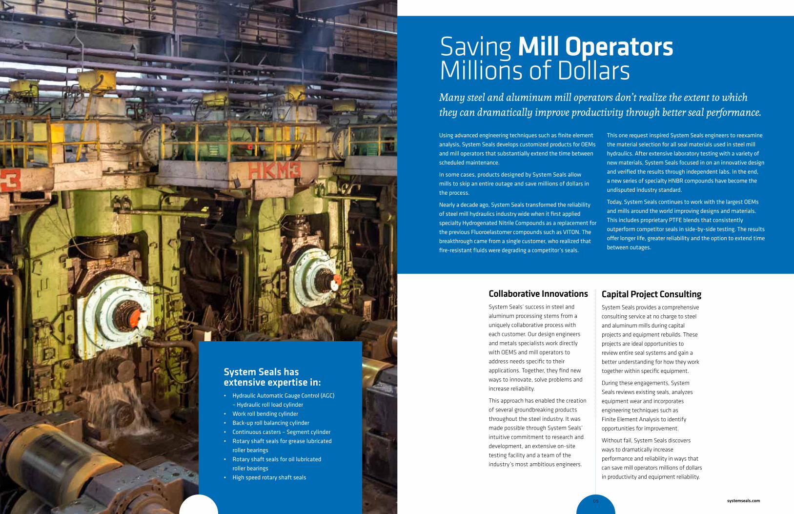
Saving mill Operators Millions of DollarsMany steel and aluminum mill operators don’t realize the extent to which they can dramatically improve productivity through better seal performance.
Using advanced engineering techniques such as finite element
analysis, System Seals develops customized products for OEMs
and mill operators that substantially extend the time between
scheduled maintenance.
In some cases, products designed by System Seals allow
mills to skip an entire outage and save millions of dollars in
the process.
Nearly a decade ago, System Seals transformed the reliability
of steel mill hydraulics industry wide when it first applied
specialty Hydrogenated Nitrile Compounds as a replacement for
the previous Fluoroelastomer compounds such as VITON. The
breakthrough came from a single customer, who realized that
fire-resistant fluids were degrading a competitor’s seals.
This one request inspired System Seals engineers to reexamine
the material selection for all seal materials used in steel mill
hydraulics. After extensive laboratory testing with a variety of
new materials, System Seals focused in on an innovative design
and verified the results through independent labs. In the end,
a new series of specialty HNBR compounds have become the
undisputed industry standard.
Today, System Seals continues to work with the largest OEMs
and mills around the world improving designs and materials.
This includes proprietary PTFE blends that consistently
outperform competitor seals in side-by-side testing. The results
offer longer life, greater reliability and the option to extend time
between outages.
system seals has extensive expertise in: • Hydraulic Automatic Gauge Control (AGC)
– Hydraulic roll load cylinder
• Work roll bending cylinder
• Back-up roll balancing cylinder
• Continuous casters – Segment cylinder
• Rotary shaft seals for grease lubricated
roller bearings
• Rotary shaft seals for oil lubricated
roller bearings
• High speed rotary shaft seals
08 09 systemseals.com
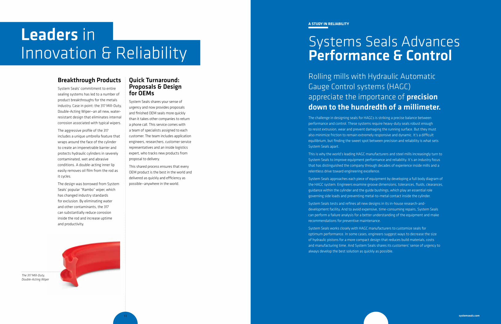
Breakthrough Products System Seals’ commitment to entire
sealing systems has led to a number of
product breakthroughs for the metals
industry. Case in point: the 317 Mill-Duty,
Double-Acting Wiper—an all new, water-
resistant design that eliminates internal
corrosion associated with typical wipers.
The aggressive profile of the 317
includes a unique umbrella feature that
wraps around the face of the cylinder
to create an impenetrable barrier and
protects hydraulic cylinders in severely
contaminated, wet and abrasive
conditions. A double-acting inner lip
easily removes oil film from the rod as
it cycles.
The design was borrowed from System
Seals’ popular “Rambo” wiper, which
has changed industry standards
for exclusion. By eliminating water
and other contaminants, the 317
can substantially reduce corrosion
inside the rod and increase uptime
and productivity.
a stUdy iN reliability
Systems Seals Advances Performance & ControlRolling mills with Hydraulic Automatic Gauge Control systems (HAGC) appreciate the importance of precision down to the hundredth of a millimeter. The challenge in designing seals for HAGCs is striking a precise balance between
performance and control. These systems require heavy-duty seals robust enough
to resist extrusion, wear and prevent damaging the running surface. But they must
also minimize friction to remain extremely responsive and dynamic. It’s a difficult
equilibrium, but finding the sweet spot between precision and reliability is what sets
System Seals apart.
This is why the world’s leading HAGC manufacturers and steel mills increasingly turn to
System Seals to improve equipment performance and reliability. It’s an industry focus
that has distinguished the company through decades of experience inside mills and a
relentless drive toward engineering excellence.
System Seals approaches each piece of equipment by developing a full body diagram of
the HAGC system. Engineers examine groove dimensions, tolerances, fluids, clearances,
guidance within the cylinder and the guide bushings, which play an essential role
governing side loads and preventing metal-to-metal contact inside the cylinder.
System Seals tests and refines all new designs in its in-house research-and-
development facility. And to avoid expensive, time-consuming repairs, System Seals
can perform a failure analysis for a better understanding of the equipment and make
recommendations for preventive maintenance.
System Seals works closely with HAGC manufacturers to customize seals for
optimum performance. In some cases, engineers suggest ways to decrease the size
of hydraulic pistons for a more compact design that reduces build materials, costs
and manufacturing time. And System Seals shares its customers’ sense of urgency to
always develop the best solution as quickly as possible.
Quick turnaround: Proposals & Design for OemsSystem Seals shares your sense of
urgency and now provides proposals
and finished OEM seals more quickly
than it takes other companies to return
a phone call. This service comes with
a team of specialists assigned to each
customer. The team includes application
engineers, researchers, customer service
representatives and an inside logistics
expert, who tracks new products from
proposal to delivery.
This shared process ensures that every
OEM product is the best in the world and
delivered as quickly and efficiency as
possible—anywhere in the world.
leaders in Innovation & Reliability
The 317 Mill-Duty, Double-Acting Wiper
10 11 systemseals.com
440 440 421
cross-section of seal installation drawing iconcross-section of seal installation drawing iconcross-section of seal installation drawing icon
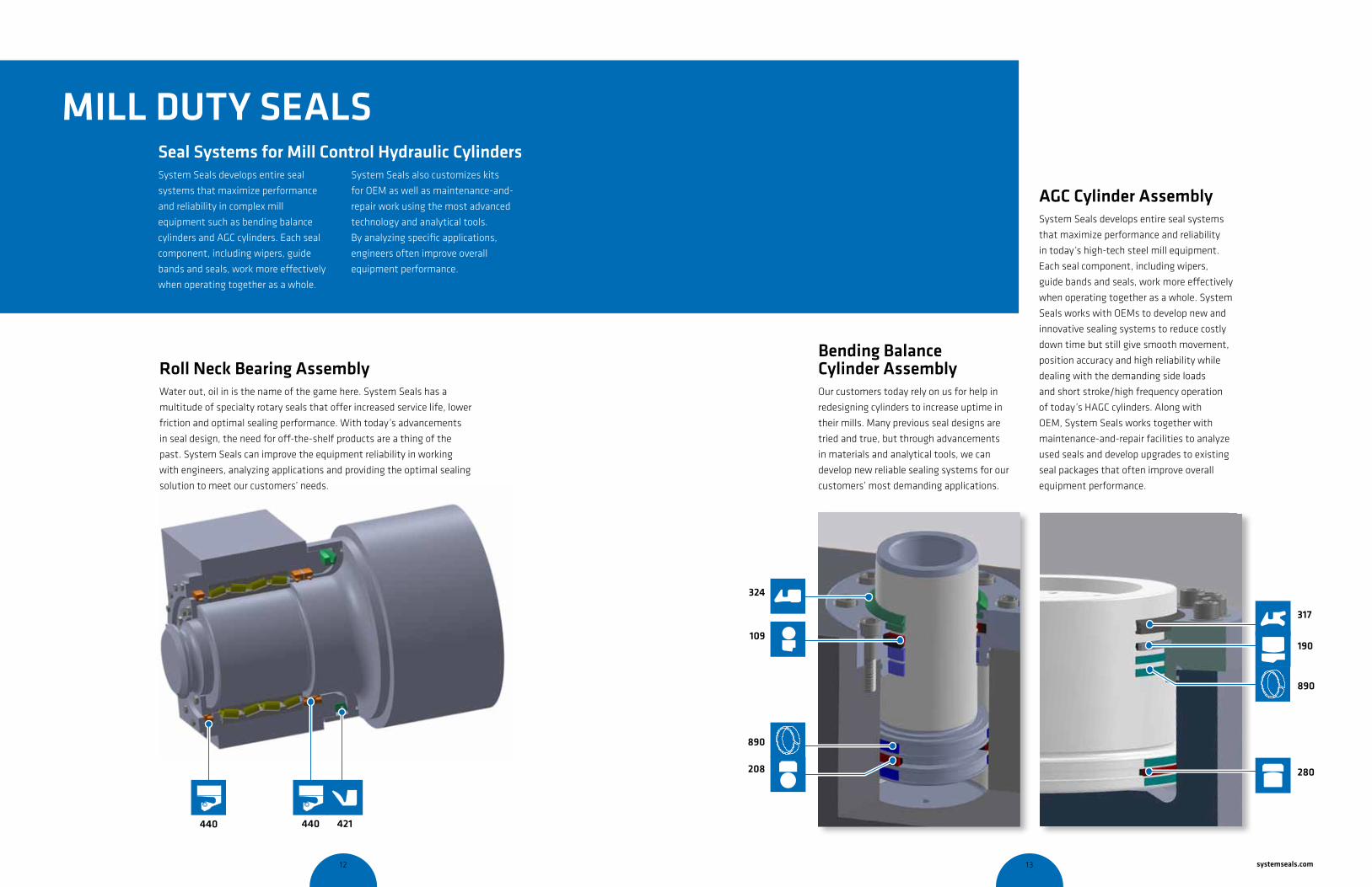
System Seals develops entire seal
systems that maximize performance
and reliability in complex mill
equipment such as bending balance
cylinders and AGC cylinders. Each seal
component, including wipers, guide
bands and seals, work more effectively
when operating together as a whole.
System Seals also customizes kits
for OEM as well as maintenance-and-
repair work using the most advanced
technology and analytical tools.
By analyzing specific applications,
engineers often improve overall
equipment performance.
seal systems for mill Control Hydraulic Cylinders
Bending Balance Cylinder AssemblyOur customers today rely on us for help in
redesigning cylinders to increase uptime in
their mills. Many previous seal designs are
tried and true, but through advancements
in materials and analytical tools, we can
develop new reliable sealing systems for our
customers’ most demanding applications.
324
109
890
208
cross-section of seal installation drawing icon
cross-section of seal installation drawing icon
cross-section of seal installation drawing icon
cross-section of seal installation drawing icon
317
190
280
890
cross-section of seal installation drawing icon
cross-section of seal installation drawing icon
cross-section of seal installation drawing icon
cross-section of seal installation drawing icon
mill Duty seAls
AGC Cylinder AssemblySystem Seals develops entire seal systems
that maximize performance and reliability
in today’s high-tech steel mill equipment.
Each seal component, including wipers,
guide bands and seals, work more effectively
when operating together as a whole. System
Seals works with OEMs to develop new and
innovative sealing systems to reduce costly
down time but still give smooth movement,
position accuracy and high reliability while
dealing with the demanding side loads
and short stroke/high frequency operation
of today’s HAGC cylinders. Along with
OEM, System Seals works together with
maintenance-and-repair facilities to analyze
used seals and develop upgrades to existing
seal packages that often improve overall
equipment performance.
Roll neck Bearing AssemblyWater out, oil in is the name of the game here. System Seals has a
multitude of specialty rotary seals that offer increased service life, lower
friction and optimal sealing performance. With today’s advancements
in seal design, the need for off-the-shelf products are a thing of the
past. System Seals can improve the equipment reliability in working
with engineers, analyzing applications and providing the optimal sealing
solution to meet our customers’ needs.
12 13 systemseals.com
mill Duty seAls product listing
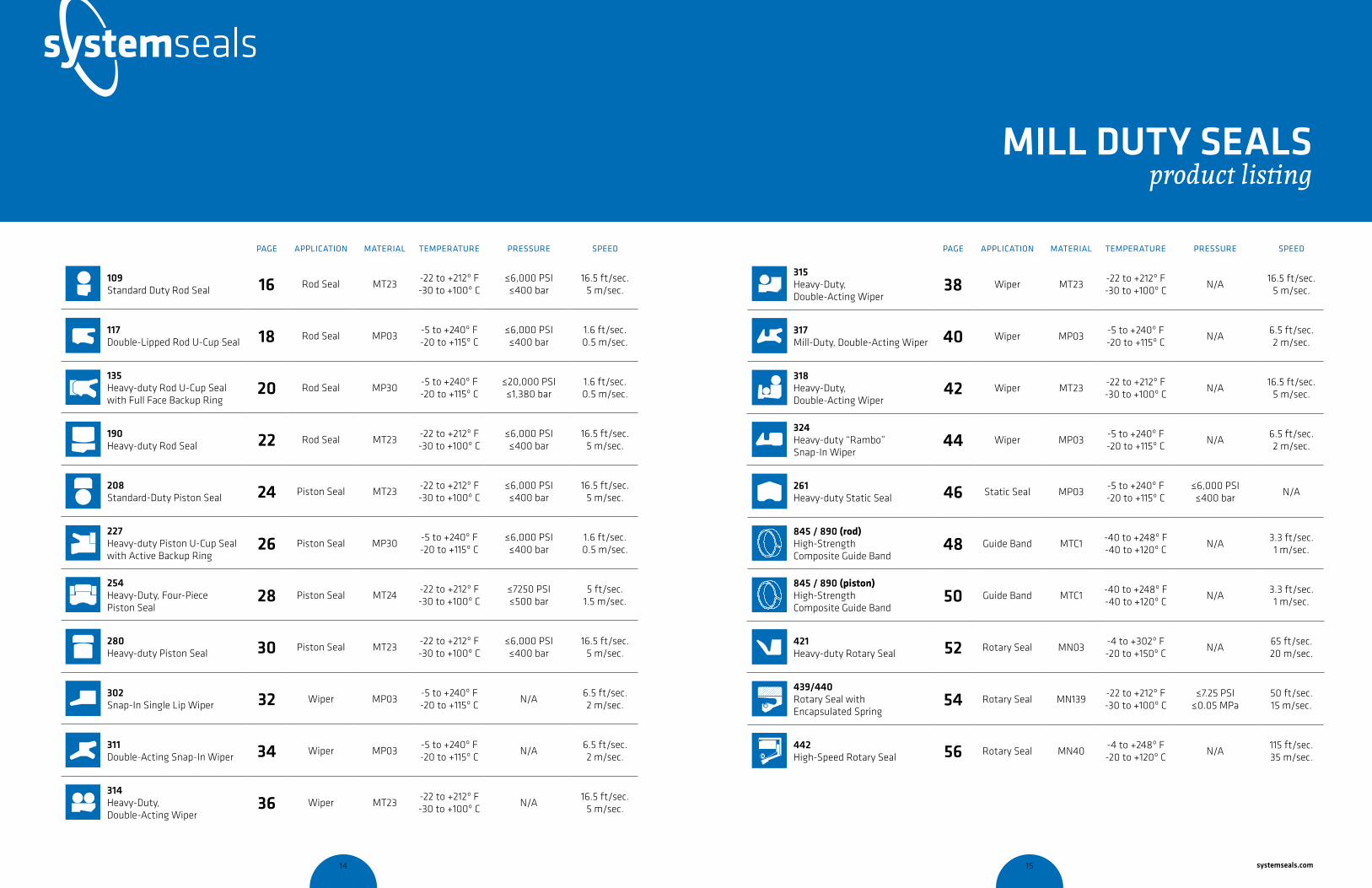
Product PAGE APPlICATION MATERIAl TEMPERATURE PRESSURE SPEEd
cross-section of seal installation drawing icon
109Standard Duty Rod Seal 16 Rod Seal MT23
-22 to +212º F-30 to +100º C
≤6,000 PSI≤400 bar
16.5 ft/sec.5 m/sec.
cross-section of seal installation drawing icon
117 Double-Lipped Rod U-Cup Seal 18 Rod Seal MP03
-5 to +240º F-20 to +115º C
≤6,000 PSI≤400 bar
1.6 ft/sec.0.5 m/sec.
cross-section of seal installation drawing icon
135 Heavy-duty Rod U-Cup Seal with Full Face Backup Ring
20 Rod Seal MP30-5 to +240º F-20 to +115º C
≤20,000 PSI≤1,380 bar
1.6 ft/sec.0.5 m/sec.
cross-section of seal installation drawing icon
190 Heavy-duty Rod Seal 22 Rod Seal MT23
-22 to +212º F-30 to +100º C
≤6,000 PSI≤400 bar
16.5 ft/sec.5 m/sec.
cross-section of seal installation drawing icon
208Standard-Duty Piston Seal 24 Piston Seal MT23
-22 to +212º F-30 to +100º C
≤6,000 PSI≤400 bar
16.5 ft/sec.5 m/sec.
cross-section of seal installation drawing icon
227 Heavy-duty Piston U-Cup Seal with Active Backup Ring
26 Piston Seal MP30-5 to +240º F-20 to +115º C
≤6,000 PSI≤400 bar
1.6 ft/sec.0.5 m/sec.
cross-section of seal installation drawing icon
254 Heavy-Duty, Four-Piece Piston Seal
28 Piston Seal MT24-22 to +212º F-30 to +100º C
≤7250 PSI≤500 bar
5 ft/sec.1.5 m/sec.
cross-section of seal installation drawing icon
280Heavy-duty Piston Seal 30 Piston Seal MT23
-22 to +212º F-30 to +100º C
≤6,000 PSI≤400 bar
16.5 ft/sec.5 m/sec.
cross-section of seal installation drawing icon
302 Snap-In Single Lip Wiper 32 Wiper MP03
-5 to +240º F-20 to +115º C
N/A6.5 ft/sec.2 m/sec.
cross-section of seal installation drawing icon
311 Double-Acting Snap-In Wiper 34 Wiper MP03
-5 to +240º F-20 to +115º C
N/A6.5 ft/sec.2 m/sec.
cross-section of seal installation drawing icon
314 Heavy-Duty, Double-Acting Wiper
36 Wiper MT23-22 to +212º F-30 to +100º C
N/A16.5 ft/sec.
5 m/sec.
Product PAGE APPlICATION MATERIAl TEMPERATURE PRESSURE SPEEd
cross-section of seal installation drawing icon
315 Heavy-Duty, Double-Acting Wiper
38 Wiper MT23-22 to +212º F-30 to +100º C
N/A16.5 ft/sec.
5 m/sec.
cross-section of seal installation drawing icon
317 Mill-Duty, Double-Acting Wiper 40 Wiper MP03
-5 to +240º F-20 to +115º C
N/A6.5 ft/sec.2 m/sec.
cross-section of seal installation drawing icon
318 Heavy-Duty, Double-Acting Wiper
42 Wiper MT23-22 to +212º F-30 to +100º C
N/A16.5 ft/sec.
5 m/sec.
cross-section of seal installation drawing icon
324Heavy-duty “Rambo” Snap-In Wiper
44 Wiper MP03-5 to +240º F-20 to +115º C
N/A6.5 ft/sec.2 m/sec.
cross-section of seal installation drawing icon
261 Heavy-duty Static Seal 46 Static Seal MP03
-5 to +240º F-20 to +115º C
≤6,000 PSI≤400 bar
N/A
cross-section of seal installation drawing icon
845 / 890 (rod)High-Strength Composite Guide Band
48 Guide Band MTC1-40 to +248º F-40 to +120º C
N/A3.3 ft/sec.1 m/sec.
cross-section of seal installation drawing icon
845 / 890 (piston)High-Strength Composite Guide Band
50 Guide Band MTC1-40 to +248º F-40 to +120º C
N/A3.3 ft/sec.1 m/sec.
cross-section of seal installation drawing icon
421Heavy-duty Rotary Seal 52 Rotary Seal MN03
-4 to +302º F-20 to +150º C
N/A65 ft/sec.20 m/sec.
cross-section of seal installation drawing icon
439/440Rotary Seal with Encapsulated Spring
54 Rotary Seal MN139-22 to +212º F-30 to +100º C
≤7.25 PSI≤0.05 MPa
50 ft/sec.15 m/sec.
cross-section of seal installation drawing icon
442High-Speed Rotary Seal 56 Rotary Seal MN40
-4 to +248º F-20 to +120º C
N/A115 ft/sec.35 m/sec.
14 15 systemseals.com

systemseals.com | 9505 Midwest Avenue, Cleveland, OH 44125 | 440.735.0200
DESCRIPTION The 109 Series rod seal is a low-friction design, consisting of a Teflon seal and an O-ring energizer. The sealing lip design is optimized to ensure maximum sealing performance at both low and high pressures. The lip design features a “pump-back” capability, which eliminates pressure trapping when used as a buffer seal in a Zero-Leak Technology configuration.
PRODUCT BENEFITS • Low friction • High-speed applications• High-temperature resistance• Low wear• Extrusion resistant• Compatible with a wide range of media• Available in diameters up to 2 meters
APPLICATIONSThe 109 Series Rod Seal is ideal for high-pressure sealing applications, offering low-friction performance and high-speed capability.
Typical applications include:
• Injection Molding • Mobile Hydraulics• Hydraulic Presses • Used as a buffer seal in a Zero-Leak
Technology System
MATERIAL System Seals’ unique Teflon compounds provide ultra-low friction and high-speed performance with minimal wear. The standard compounds are Teflon with Bronze filler, or Teflon filled with Glass-Moly. The temperature range of the seal can be increased by selecting a FPM O-ring in place of the standard NBR O-ring.
Material Code
PTFE-Bronze compound + NBR o-ring (shown in photo) MT23
PTFE-Bronze compound + FPM o-ring MT26
PTFE-Glass/MoS2 compound + NBR o-ring MT83
PTFE-Glass/MoS2 compound + FPM o-ring MT86
OPERATING PARAMETERS
MT23 MT83
Temperature ºC ºF ºC ºF
hydraulic oil -30... +100 -22... +212 -30... +100 -22... +212
water oil emulsions (HFA) - - +5... +60 +40... +140
water-glycol fluids (HFC) - - -30... +60 -22... +140
polyol esters (HFD) - - - -
water - - -5... +100 +40... +212
speed 5 m/s (16.5 ft/sec)
pressure 400 bar (6000psi)
Note: for other materials or fluids please contact our engineering department.
Above: Installation Drawing
Features: O-Ring energizer
Low Friction Teflon compound
Optimized seal-lip position
Wedge-shaped profile ensures pump-back capability
Easy to install
109seriesSTANDARD DUTY ROD SEAL
cross-section of seal installation drawing icon
systemseals.com | 9505 Midwest Avenue, Cleveland, OH 44125 | 216.220.1800
METRIC SERIESB ØD L +0.2 ØD1 <200bar ØD1 <400bar R
Series 1 2.45 mm d + 4.90 2.20 d + 0.40 d + 0.30 0.30
Series 2 3.65 mm d + 7.30 3.20 d + 0.50 d + 0.30 0.50
Series 3 5.35 mm d + 10.70 4.20 d + 0.50 d + 0.40 0.80
Series 4 7.55 mm d + 15.10 6.30 d + 0.50 d + 0.40 1.20
Series 5 10.25 mm d + 20.50 8.10 d + 0.60 d + 0.50 2.00
Series 6 12.00 mm d + 24.00 8.10 d + 0.60 d + 0.50 2.00
Series 7 13.65 mm d + 27.30 9.50 d + 0.70 d + 0.50 2.00
INCH SERIESB ØD L +0.008” ØD1 <3000psi ØD1 <6000psi R
Series 1 0.096 in d + 0.192 0.087 d + 0.016 d + 0.012 0.012
Series 2 0.144 in d + 0.288 0.126 d + 0.020 d + 0.012 0.020
Series 3 0.211 in d + 0.422 0.165 d + 0.020 d + 0.016 0.031
Series 4 0.297 in d + 0.594 0.248 d + 0.020 d + 0.016 0.047
Series 5 0.404 in d + 0.808 0.319 d + 0.024 d + 0.020 0.079
Series 6 0.472 in d + 0.944 0.319 d + 0.024 d + 0.020 0.079
Series 7 0.537 in d + 1.074 0.374 d + 0.028 d + 0.020 0.079
Note: The extrusion gap “E” is suitable for pressure up to 400bar (6000 psi) and tempera-tures up to 80° C (176° F). For higher pressures or temperatures, please consult our engi-neering department for guidance.
SURFACE FINISHSurface roughness Ra Rt RMS
Sliding surface ≤0.3 µm ≤3 µm 8 RMS
Surface of groove I.D. ≤1.8 µm ≤10 µm 64 RMS
Sides of groove ≤3 µm ≤16 µm 125 RMS
Ød C
≤50mm 3.00
50mm < 120mm 4.00
120mm < 200mm 6.00
200mm < 650mm 8.00
650mm < 950mm 11.00
Ød C
<2.0 in 0.120
2.0 in < 4.7 in 0.160
4.7 in < 7.9 in 0.240
7.9 in < 25.6 in 0.320
25.6 in < 37.4 in 0.450
DESIGN GUIDELINES
109series
rounded &burr freeC x 20o
LR
B
Ød
f8
rod
ØD
1 H
9
ØD
H8
STANDARD DUTY ROD SEAL
LEAD-IN CHAMFERS
16 17 systemseals.com

systemseals.com | 9505 Midwest Avenue, Cleveland, OH 44125 | 440.735.0200
DESCRIPTION The 117 Series U-cup seal is a high-performance, double-lipped seal for use as a primary seal, typically in moderate to high-pressure applications. Its asymmetrical design ensures that the seal lip forces are optimized for every cross section and diameter. Manufactured in a variety of materials and sizes from 6mm up to 2 meters in standard or custom diameters.
PRODUCT BENEFITS • High pressure capability and wide
temperature range • Excellent fluid compatibility including
water-based fluids (H-PU)• Exceptional abrasion resistance• Highly extrusion resistant • Available in diameters up to 2 meters
APPLICATIONSThe 117 Series U-cup seal is typically used as a primary seal in moderate to high-pressure applications.
Typical applications include:
• Mining• Agricultural Hydraulics• Construction Equipment • Presses• Injection Molding Machines
MATERIAL The 117 Series rod seal is manufactured from high-grade hydrolysis-resistant polyurethane. The series is also available in NBR and FPM.
Material Code
Polyurethane H-PU (shown in photo) MPO3
Polyurethane TPU MP50
OPERATING PARAMETERS
MPO3 MP50
Temperature ºC ºF ºC ºF
hydraulic oil -20…+115 -5…+240 -30…+110 -20…+230
water oil emulsions (HFA) +5…+55 +40…+130 +5…+50 +40…+120
water-glycol fluids (HFC) -20…+55 -5….+130 -30…+40 -20…+100
polyol esters (HFD) - - - -
water +5…+55 +40…+130 +5…+50 +40…+120
speed 0.5 m/s (1.6 ft/sec)
pressure ≤400 bar (6000psi)
Note: for other materials or fluids please contact our engineering department.
Above: Installation Drawing
Features: Premium wear resistance
Secondary lip adds to seal performance and acts as a contamination barrier
Easy to install
117 seriesDOUBLE-LIPPED ROD U-CUP SEAL
cross-section of seal installation drawing icon
systemseals.com | 9505 Midwest Avenue, Cleveland, OH 44125 | 440.735.0200
METRIC SERIESB L +0.2 H ØD ØD1 R C
Series 1 4.00 mm 6.30 5.70 d + 8.00 d + E 0.40 2.50
Series 2 4.00 mm 9.00 8.10 d + 8.00 d + E 0.40 2.50
Series 3 4.00 mm 11.00 9.90 d + 8.00 d + E 0.40 2.50
Series 4 5.00 mm 8.00 7.20 d + 10.00 d + E 0.40 4.00
Series 5 5.00 mm 11.00 9.90 d + 10.00 d + E 0.40 4.00
Series 6 7.50 mm 12.50 11.30 d + 15.00 d + E 0.40 5.00
Series 7 10.00 mm 16.00 14.40 d + 20.00 d + E 0.40 6.00
Series 8 15.00 mm 19.00 17.00 d + 30.00 d + E 0.40 7.50
INCH SERIESB L +0.008 H ØD ØD1 R C
Series 1 0.250 in 0.413 0.375 d + 0.500 d + E 0.016 0.195
Series 2 0.375 in 0.619 0.563 d + 0.750 d + E 0.016 0.195
Series 3 0.500 in 0.825 0.750 d + 1.000 d + E 0.016 0.250
Series 4 0.563 in 0.928 0.844 d + 1.125 d + E 0.016 0.295
Series 5 0.625 in 1.031 0.938 d + 1.250 d + E 0.016 0.295
Series 6 0.750 in 1.238 1.125 d + 1.500 d + E 0.016 0.400
Series 7 1.000 in 1.650 1.500 d + 2.000 d + E 0.016 0.500
Note: for higher pressures or temperatures, please consult our engineering department for guidance. For a complete list of available sizes please refer to the System Seals online product catalogue at www.systemseals.com.
SURFACE FINISHSurface roughness Ra Rt RMS
Sliding surface ≤0.3 µm ≤3 µm 8 RMS
Surface of groove I.D. ≤1.8 µm ≤10 µm 64 RMS
Sides of groove ≤3 µm ≤16 µm 125 RMS
Pressure E
≤100 bar 0.50
≤250 bar 0.35
≤400 bar 0.25
Extrusion Gaps
Pressure E
≤1450 psi 0.020
≤3625 psi 0.015
≤6000 psi 0.010
Extrusion Gaps
DESIGN GUIDELINES
117 series
L
R
C x 300
rounded &burr free
B
E/2
Ød
f8
ØD
1 H
9
ØD
H8
H
DOUBLE-LIPPED ROD U-CUP SEAL
18 19 systemseals.com

systemseals.com | 9505 Midwest Avenue, Cleveland, OH 44125 | 440.735.0200
DESCRIPTION The 135 Series U-cup seal is a popular choice to replace V-packing sets. It is a high-performance, double-lipped seal for use as in high-clearance applications, typically in moderate to high-pressure environments. Its full-face backup ring encapsulates the seal to add stability under high-pressure conditions, while preventing extrusion. The asymmetrical design of the U-cup ensures the lip forces are optimized for every cross section and diameter. Manufactured in a variety of ma-terials and sizes from 6mm up to 2 meters in standard or custom diameters.
PRODUCT BENEFITS • Designed specifically for large
clearance applications• High pressure capability and wide
temperature range • Excellent fluid compatibility including
water-based fluids (H-PU)• Exceptional abrasion resistance• Highly extrusion resistant • Available in diameters up to 2 meters
APPLICATIONSThe 135 Series U-cup seal is typically used in high-clearance applications as a primary seal and functions well in moderate to high pressures.
Typical applications include:• Steel and aluminum processing• Mining• Agriculture • Construction equipment • Presses & injection molding machines
MATERIAL The 135 Series rod seal features high-grade polyurethane. Standard materials are P03 machined H-PU, available up to 2 meters in diameter. To suit a variety of applications the series is also available in NBR, H-NBR, EPDM and high temperature-resistant FPM. The backup ring materials include POM, Nylon, PTFE with bronze filler and PEEK.
Material Code
Polyurethane H-PU / POM (shown in photo) MP30
Hydrogenated NBR, PTFE/Bz MN32
OPERATING PARAMETERS
MP30
Temperature ºC ºF
hydraulic oil -20…+115 -5…+240
water oil emulsions (HFA) +5…+55 +40…+130
water-glycol fluids (HFC) -20…+55 -5….+130
polyol esters (HFD) - -
water +5…+55 +40…+130
speed 0.5 m/s (1.6 ft/sec)
pressure ≤1380 bar (20,000psi)
Note: for other materials or fluids please contact our engineering department.
Above: Installation Drawing
Features: Premium wear resistance
Secondary lip adds to seal performance and acts as a contamination barrier
Robust backup ring prevents extrusion and adds stability to the seal
Direct retrofit for V-packing sets
Easy to install
cross-section of seal installation drawing icon
135seriesHEAVY DUTY ROD U-CUP SEAL WITH FULL FACE BACKUP RING
systemseals.com | 9505 Midwest Avenue, Cleveland, OH 44125 | 440.735.0200
DESIGN GUIDELINES
135series
H
L
R
C x 30 0
rounded &burr free
B
E/2
Ød
f8
ØD
1 H
9
ØD
H8
HEAVY DUTY ROD U-CUP SEAL WITH FULL FACE BACKUP RING
METRIC SERIESB L +0.20 H ØD ØD1 R C
Series 1 5.0 12.00 10.80 d+10 d+E 0.40 2.50
Series 2 7.5 16.00 14.75 d+15 d+E 0.40 3.75
Series 3 10.0 22.00 20.75 d+20 d+E 0.40 5.00
Series 4 12.5 27.00 25.75 d+25 d+E 0.40 6.25
Series 5 15.0 35.00 33.75 d+30 d+E 0.40 7.50
INCH SERIESB L +0.008 H ØD ØD1 R C
Series 1 0.250 0.550 0.495 d+0.500 d+E 0.016 0.125
Series 2 0.375 0.825 0.743 d+0.750 d+E 0.016 0.188
Series 3 0.500 1.125 1.013 d+1.000 d+E 0.016 0.250
Series 4 0.625 1.375 1.238 d+1.250 d+E 0.016 0.313
Series 5 0.750 1.750 1.575 d+1.500 d+E 0.016 0.375
Note: for higher pressures or temperatures, please consult our engineering department for guidance. For a complete list of available sizes please refer to the System Seals online product catalogue at www.systemseals.com.
SURFACE FINISHSurface roughness Ra Rt RMS
Sliding surface ≤0.3 µm ≤3 µm 8 RMS
Surface of groove I.D. ≤1.8 µm ≤10 µm 64 RMS
Sides of groove ≤3 µm ≤16 µm 125 RMS
Pressure E
≤100 bar 1.00
≤250 bar 0.85
≤400 bar 0.70
Extrusion Gaps
Pressure E
≤1450 psi 0.040
≤3625 psi 0.035
≤6000 psi 0.030
Extrusion Gaps
20 21 systemseals.com

systemseals.com | 9505 Midwest Avenue, Cleveland, OH 44125 | 440.735.0200
DESCRIPTION The 190 Series rod seal is a heavy-duty, low-friction design, consisting of a Teflon seal and a profiled energizer. It is designed for large diameter and challenging applications, where high pressure and large extrusion gaps exist. The seal is ideal for short-stroke, dithering applications.
PRODUCT BENEFITS • Low friction • Short-stroke applications• High-temperature resistance• Low wear• Extrusion resistant• Compatible with a wide range of media• Available in diameters up to 2 meters.
APPLICATIONSThe 190 Series heavy-duty rod seal is ideal for high-pressure sealing applications, offering low-friction performance and short-stroke capability.
Typical applications include:
• Rolling Mills• Injection Molding Machines • Hydraulic Presses • Forging Presses
MATERIAL System Seals’ custom blended Teflon compounds provide ultra-low friction and high-speed performance with minimal wear. The standard compounds are Teflon with Bronze filler, or Teflon filled with Glass-Moly. The temperature range of the seal can be increased by selecting a FPM energizer in place of the standard NBR energizer.
Material Code
PTFE-Bronze compound + NBR energizer MT23
PTFE-Bronze compound + FPM energizer MT26
PTFE-Glass/MoS2 compound + NBR energizer (shown in photo) MT83
PTFE-Glass/MoS2 compound + FPM energizer MT86
OPERATING PARAMETERS
MT23 MT83
Temperature ºC ºF ºC ºF
hydraulic oil -30... +100 -22... +212 -30... +100 -22... +212
water oil emulsions (HFA) - - +5... +60 +40... +140
water-glycol fluids (HFC) - - -30... +60 -22... +140
polyol esters (HFD) - - - -
water - - -5... +100 +40... +212
speed 5 m/s (16.5 ft/sec)
pressure 400 bar (6000psi)
Note: for other materials or fluids please contact our engineering department.
Above: Installation Drawing
Features: Robust design
Profiled energizer ring that maintains seal force throughout service life
Optimized seal-lip position
Easy to install
No twisting during installation
190seriesHEAVY DUTY ROD SEAL
cross-section of seal installation drawing icon
systemseals.com | 9505 Midwest Avenue, Cleveland, OH 44125 | 440.735.0200
METRIC SERIESRod Diameter ØD B ØD ØD1 L+0.2 E C R
Series 1 <200mm 10.00 d + 20.00 d + 0.50 10.00 0.50 7.50 0.40
Series 2 <300mm 12.50 d + 25.00 d + 0.60 12.50 0.60 10.00 0.40
Series 3 <450mm 15.00 d + 30.00 d + 0.60 15.00 0.60 12.00 0.80
Series 4 <685mm 17.50 d + 35.00 d + 0.60 17.50 0.60 12.00 1.20
Series 5 <1270mm 20.00 d + 40.00 d + 0.60 20.00 0.60 12.00 1.20
INCH SERIESRod Diameter ØD B ØD ØD1 L+0.008 E C R
Series 1 <8in 0.394 d + 0.787 d + 0.020 0.394 0.020 0.300 0.016
Series 2 <12in 0.492 d + 0.984 d + 0.024 0.492 0.024 0.390 0.016
Series 3 <18in 0.591 d + 1.181 d + 0.024 0.591 0.024 0.470 0.032
Series 4 <27in 0.689 d + 1.378 d + 0.024 0.689 0.024 0.470 0.050
Series 5 <50in 0.787 d + 1.575 d + 0.024 0.787 0.024 0.470 0.050
Note: The extrusion gap “E” is suitable for pressure up to 400 bar (6000 psi) and temperatures up to 80° C (176° F). For higher pressures or temperatures, please consult our engineering department for guidance. For a complete list of available sizes please refer to the System Seals online product catalogue at www.systemseals.com.
SURFACE FINISHSurface roughness Ra Rt RMS
Sliding surface ≤0.3 µm ≤3 µm 8 RMS
Surface of groove I.D. ≤1.8 µm ≤10 µm 64 RMS
Sides of groove ≤3 µm ≤16 µm 125 RMS
DESIGN GUIDELINES
190series
C x 20o
E/2
LR
B
rounded &burr free
Ød
rod
≤Ø50
0 f8
>Ø50
0 f7
ØD
1
ØD
H8≤Ø
500
H9
>Ø50
0 H
8
HEAVY DUTY ROD SEAL
22 23 systemseals.com

systemseals.com | 9505 Midwest Avenue, Cleveland, OH 44125 | 216.220.1800
Description The 208 Series standard-duty piston seal is a low-friction design, consisting of a Teflon seal and an O-ring energizer. It is designed for double-acting cylinders in challenging applications, where low friction and high wear resistance are needed.
proDuct Benefits • Low friction • Double-acting applications• High-temperature resistance• Low wear• Extrusion resistant• Compatible with a wide range of media• Available in diameters up to 2 meters.
ApplicAtionsThe 208 Series standard-duty piston seal is ideal for high-pressure sealing applications, offering low-friction performance and double-acting operation.
Typical applications include:
• Rolling Mills• Injection Molding Machines • Hydraulic Presses• Agricultural Hydraulics• Mobile Hydraulics
MAteriAl System Seals’ custom blended Teflon compounds provide ultra-low friction and high-speed performance with minimal wear. The standard compounds are Teflon with Bronze filler, or Teflon filled with Glass-Moly. The temperature range of the seal can be increased by selecting an FPM energizer in place of the standard NBR energizer.
Material Code
PTFE-Bronze compound + NBR o-ring (shown in photo) MT23
PTFE-Bronze compound + FPM o-ring MT26
PTFE-Glass/MoS2 compound + NBR o-ring MT83
PTFE-Glass/MoS2 compound + FPM o-ring MT86
operAting pArAMeters
MT23 MT83
Temperature ºC ºF ºC ºF
hydraulic oil -30... +100 -22... +212 -30... +100 -22... +212
water oil emulsions (HFA) - - +5... +60 +40... +140
water-glycol fluids (HFC) - - -30... +60 -22... +140
polyol esters (HFD) - - - -
water - - -5... +100 +40... +212
speed 5 m/s (16.5 ft/sec)
pressure 400 bar (6000psi)
Note: for other materials or fluids please contact our engineering department.
Above: Installation Drawing
Features: O-Ring Energizer that maintains seal force throughout service life
Double-acting design
Side notches ensure pressure exposure to the energizer during rapid pressure changes
Easy to install
208seriesSTANDARD DuTy PISTON SEAL
cross-section of seal installation drawing icon
systemseals.com | 9505 Midwest Avenue, Cleveland, OH 44125 | 216.220.1800
Metric seriesB Ød L+0.2 Ød1 <200bar Ød1 <400bar R
Series 1 2.45 mm D - 4.90 2.20 D - 0.40 D - 0.30 0.30
Series 2 3.75 mm D - 7.50 3.20 D - 0.50 D - 0.30 0.51
Series 3 5.50 mm D - 11.00 4.20 D - 0.50 D - 0.40 0.81
Series 4 7.75 mm D - 15.50 6.30 D - 0.50 D - 0.40 1.27
Series 5 10.50 mm D - 21.00 8.10 D - 0.60 D - 0.50 2.03
Series 6 12.25 mm D - 24.50 8.10 D - 0.60 D - 0.50 2.03
Series 7 14.00 mm D - 28.00 9.50 D - 0.60 D - 0.50 2.03
inch seriesB Ød L+0.008” Ød1 <3000psi Ød1 <6000psi R
Series 1 0.096 in D - 0.192 0.086 D - 0.016 D - 0.012 0.012
Series 2 0.148 in D - 0.296 0.126 D - 0.020 D - 0.012 0.020
Series 3 0.216 in D - 0.432 0.165 D - 0.020 D - 0.016 0.032
Series 4 0.305 in D - 0.610 0.248 D - 0.020 D - 0.016 0.050
Series 5 0.413 in D - 0.826 0.319 D - 0.024 D - 0.020 0.080
Series 6 0.482 in D - 0.964 0.319 D - 0.024 D - 0.020 0.080
Series 7 0.551 in D - 1.102 0.374 D - 0.024 D - 0.020 0.080
Note: The extrusion gap “E” is suitable for pressure up to 400bar (6000 psi) and tempera-tures up to 80° C (176° F). For higher pressures or temperatures, please consult our engi-neering department for guidance. For a complete list of available sizes please refer to the System Seals online product catalogue at www.systemseals.com.
surfAce finishSurface roughness Ra Rt RMS
Sliding surface ≤0.3 µm ≤3 µm 8 RMS
Surface of groove I.D. ≤1.8 µm ≤10 µm 64 RMS
Sides of groove ≤3 µm ≤16 µm 125 RMS
Design guiDelines
Ød
h8
ØD
H8
Bore
Ød1
h9
2 pl
aces
L
R
rounded &burr free
C
20°
B
STANDARD DuTy PISTON SEAL 208series
Ød C
≤40mm 4.00
40mm < 80mm 6.00
80mm < 133mm 8.00
133mm < 330mm 10.00
330mm < 670mm 12.00
670mm < 950mm 14.00
Ød C
<1.5 in 0.160
1.5 in < 3.0 in 0.240
3.0 in < 5.25 in 0.320
5.25 in < 13.0 in 0.400
13.0 in < 26.0 in 0.500
26.0 in < 37.5 in 0.550
leAD-in chAMfers
24 25 systemseals.com
systemseals.com | 9505 Midwest Avenue, Cleveland, OH 44125 | 440.735.0200
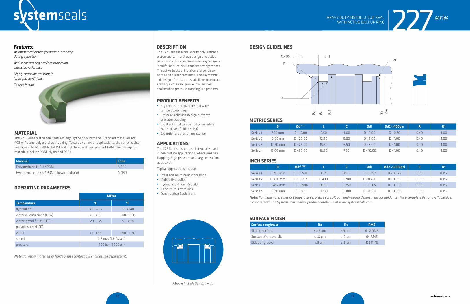
DESCRIPTION The 227 Series is a heavy duty polyurethane piston seal with a U-cup design and active backup ring. This pressure-relieving design is ideal for back-to-back tandem arrangements. The active backup ring allows larger clear-ances and higher pressures. The asymmetri-cal design of the U-cup seal allows maximum stability in the seal groove. It is an ideal choice when pressure trapping is a problem.
PRODUCT BENEFITS • High pressure capability and wide
temperature range• Pressure-relieving design prevents
pressure trapping • Excellent fluid compatibility including
water-based fluids (H-PU)• Exceptional abrasion resistance
APPLICATIONSThe 227 Series piston seal is typically used in heavy-duty applications, where pressure trapping, high pressure and large extrusion gaps exist.
Typical applications include:
• Steel and Aluminum Processing • Mobile Hydraulics• Hydraulic Cylinder Rebuild• Agricultural Hydraulics• Construction Equipment
MATERIAL The 227 Series piston seal features high-grade polyurethane. Standard materials are P03 H-PU and polyacetal backup ring. To suit a variety of applications, the series is also available in NBR, H-NBR, EPDM and high temperature-resistant FPM. The backup ring materials include POM, Nylon and PEEK.
Material Code
Polyurethane H-PU / POM MP30
Hydrogenated NBR / POM (shown in photo) MN30
OPERATING PARAMETERS
MP30 MP30
Temperature ºC ºF
hydraulic oil -20…+115 -5…+240
water oil emulsions (HFA) +5…+55 +40…+130
water-glycol fluids (HFC) -20…+55 -5….+130
polyol esters (HFD) - -
water +5…+55 +40…+130
speed 0.5 m/s (1.6 ft/sec)
pressure 400 bar (6000psi)
Note: for other materials or fluids please contact our engineering department.
Above: Installation Drawing
Features: Asymmetrical design for optimal stability during operation
Active backup ring provides maximum extrusion resistance
Highly extrusion resistant in large gap conditions
Easy to install
series
cross-section of seal installation drawing icon
227HEAVY DUTY PISTON U-CUP SEAL WITH ACTIVE BACKUP RING
systemseals.com | 9505 Midwest Avenue, Cleveland, OH 44125 | 440.735.0200
METRIC SERIESB Ød+0.20 L C Ød1 Ød2 <400bar R R1
Series 1 7.50 mm D - 15.00 9.50 4.00 D - 5.00 D - 0.70 0.40 4.00
Series 2 10.00 mm D - 20.00 12.50 5.00 D - 6.00 D - 1.00 0.40 4.00
Series 3 12.50 mm D - 25.00 15.50 6.50 D - 8.00 D - 1.00 0.40 4.00
Series 4 15.00 mm D - 30.00 18.60 7.50 D - 10.00 D - 1.00 0.40 4.00
INCH SERIESB Ød+0.008” L C Ød1 Ød2 <6000psi R R1
Series 1 0.295 mm D - 0.591 0.375 0.160 D - 0.197 D - 0.028 0.016 0.157
Series 2 0.394 mm D - 0.787 0.490 0.200 D - 0.236 D - 0.039 0.016 0.157
Series 3 0.492 mm D - 0.984 0.610 0.250 D - 0.315 D - 0.039 0.016 0.157
Series 4 0.591 mm D - 1.181 0.730 0.300 D - 0.394 D - 0.039 0.016 0.157
Note: For higher pressures or temperatures, please consult our engineering department for guidance. For a complete list of available sizes please refer to the System Seals online product catalogue at www.systemseals.com.
SURFACE FINISHSurface roughness Ra Rt RMS
Sliding surface ≤0.3 µm ≤3 µm 6-12 RMS
Surface of groove I.D. ≤1.8 µm ≤10 µm 64 RMS
Sides of groove ≤3 µm ≤16 µm 125 RMS
DESIGN GUIDELINES
Ød1
Ød
Ød2
ØD
R1
R
R1C x 200 L
Bore
series227HEAVY DUTY PISTON U-CUP SEAL WITH ACTIVE BACKUP RING
26 27 systemseals.com

systemseals.com | 9505 Midwest Avenue, Cleveland, OH 44125 | 440.735.0200
DESCRIPTION The 254 Series is one of the most robust four-piece piston seals available on the market. It consists of a profiled energizer, a Teflon seal element and two active anti-extrusion backup rings. It is designed for double-acting cylinders in heavy-duty ap-plications subject to severe pressure spikes coupled with high running clearance.
PRODUCT BENEFITS • Long service life under the
harshest conditions• Compatible with water-based fluids • Optimized for high running clearance • Easy installation
APPLICATIONSThe 254 Series, four-piece piston seal is ideal for heavy duty sealing applications where pressure spiking can occur.
Typical applications include:
• Forging Presses• Extrusion Presses • Stamping Presses• Mining• Specialty High-Pressure Cylinders• Various Advancing and
Secondary Cylinders
MATERIAL The 254 Series piston seal features a robust NBR elastomer, a seal cap in low-friction Teflon and two backup rings in high-strength thermoplastic.
Material Code
PTFE-Bronze compound /NBR / POM (shown in photo) MT24
OPERATING PARAMETERS
MT24
Temperature ºC ºF
hydraulic oil -30…+100 -22…+212
water oil emulsions (HFA) - -
water-glycol fluids (HFC) - -
polyol esters (HFD) - -
water - -
speed 1.5 m/s (5 ft/sec)
pressure 500 bar (7250psi)
Note: for other materials or fluids please contact our engineering department.
Above: Installation Drawing
Features: Low compression set profiled energizer
Low friction Teflon seal cap
Very robust design
Extrusion resistance under high pressure
series
cross-section of seal installation drawing icon
254HEAVY-DUTY, FOUR-PIECE PISTON SEAL
systemseals.com | 9505 Midwest Avenue, Cleveland, OH 44125 | 440.735.0200
METRIC SERIESB Ød L+0.2 C Ød1 <500bar R typical
Series 1 6.00 mm D-12.00 10.00 6.00 mm D-0.40 0.50
Series 2 8.50 mm D-17.00 14.00 8.00 mm D-0.50 0.50
Series 3 10.00 mm D-20.00 17.50 10.50 mm D-0.50 0.50
Series 4 12.50 mm D-25.00 19.00 10.50 mm D-0.70 0.50
INCH SERIESB Ød L+0.008” C Ød1 <7250psi R typical
Series 1 0.236 in D-0.472 0.395 0.250 inches D-0.016 0.020
Series 2 0.335 in D-0.670 0.550 0.313 inches D-0.020 0.020
Series 3 0.393 in D-0.787 0.688 0.438 inches D-0.020 0.020
Series 4 0.492 in D-0.984 0.750 0.438 inches D-0.028 0.020
Note: The extrusion gap “E” is suitable for pressure up to 500 bar (7250 psi) and temperatures up to 80° C (176° F). For higher pressures or temperatures, please consult our engineering department for guidance. For a complete list of available sizes please refer to the System Seals online product catalogue at www.systemseals.com.
SURFACE FINISHSurface roughness Ra Rt RMS
Sliding surface ≤0.3 µm ≤3 µm 6-12 RMS
Surface of groove I.D. ≤1.8 µm ≤10 µm 64 RMS
Sides of groove ≤3 µm ≤16 µm 125 RMS
DESIGN GUIDELINES
200
L rounded &burr free
C
R
B
8H
DØ
9h 1dØ
8h dØ
secalP 2
eroB
series254HEAVY-DUTY, FOUR-PIECE PISTON SEAL
28 29 systemseals.com
systemseals.com | 9505 Midwest Avenue, Cleveland, OH 44125 | 440.735.0200
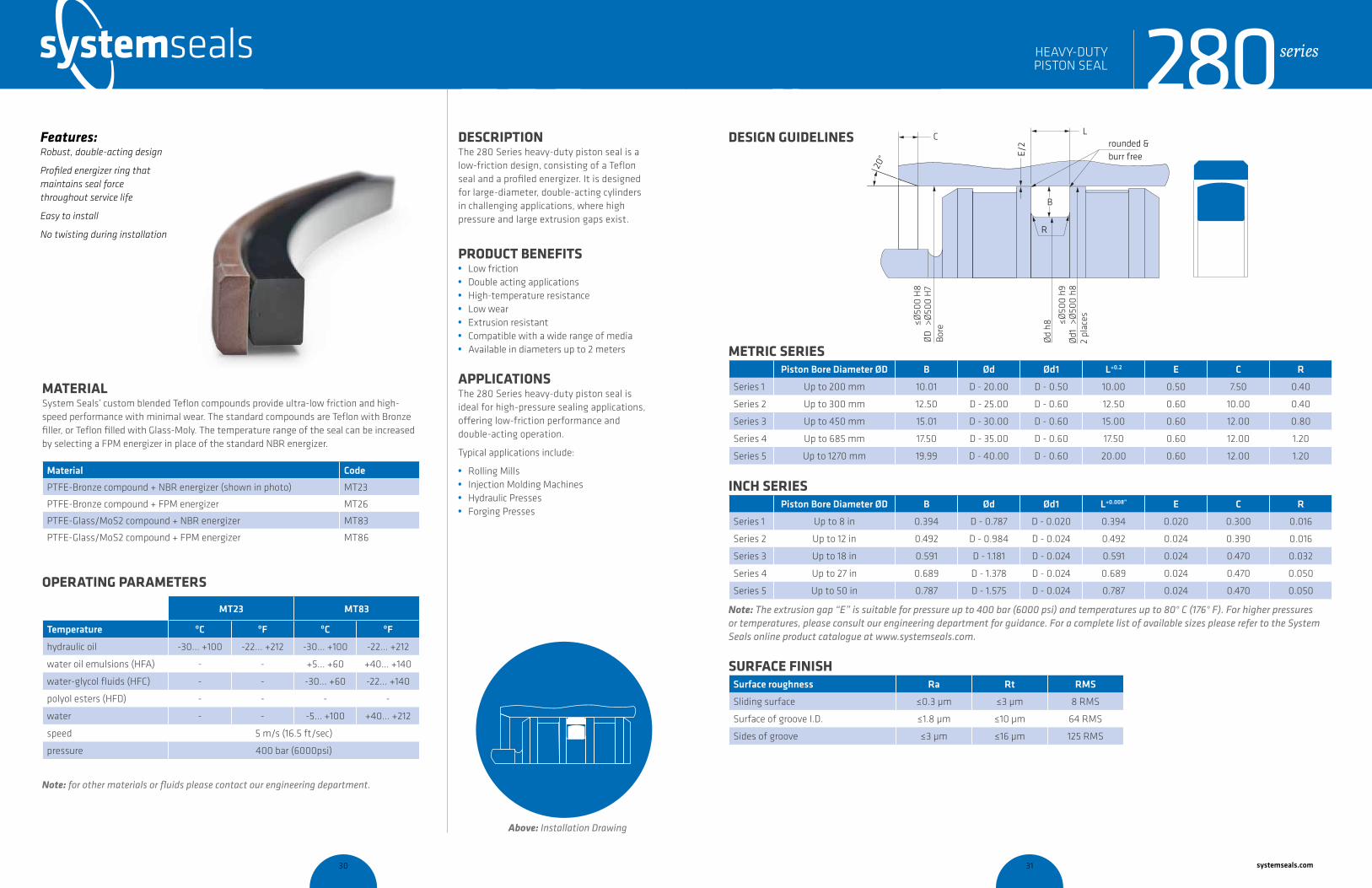
DESCRIPTION The 280 Series heavy-duty piston seal is a low-friction design, consisting of a Teflon seal and a profiled energizer. It is designed for large-diameter, double-acting cylinders in challenging applications, where high pressure and large extrusion gaps exist.
PRODUCT BENEFITS • Low friction • Double acting applications• High-temperature resistance• Low wear• Extrusion resistant• Compatible with a wide range of media• Available in diameters up to 2 meters
APPLICATIONSThe 280 Series heavy-duty piston seal is ideal for high-pressure sealing applications, offering low-friction performance and double-acting operation.
Typical applications include:
• Rolling Mills• Injection Molding Machines • Hydraulic Presses • Forging Presses
MATERIAL System Seals’ custom blended Teflon compounds provide ultra-low friction and high-speed performance with minimal wear. The standard compounds are Teflon with Bronze filler, or Teflon filled with Glass-Moly. The temperature range of the seal can be increased by selecting a FPM energizer in place of the standard NBR energizer.
Material Code
PTFE-Bronze compound + NBR energizer (shown in photo) MT23
PTFE-Bronze compound + FPM energizer MT26
PTFE-Glass/MoS2 compound + NBR energizer MT83
PTFE-Glass/MoS2 compound + FPM energizer MT86
OPERATING PARAMETERS
MT23 MT83
Temperature ºC ºF ºC ºF
hydraulic oil -30... +100 -22... +212 -30... +100 -22... +212
water oil emulsions (HFA) - - +5... +60 +40... +140
water-glycol fluids (HFC) - - -30... +60 -22... +140
polyol esters (HFD) - - - -
water - - -5... +100 +40... +212
speed 5 m/s (16.5 ft/sec)
pressure 400 bar (6000psi)
Note: for other materials or fluids please contact our engineering department.
Above: Installation Drawing
Features: Robust, double-acting design
Profiled energizer ring that maintains seal force throughout service life
Easy to install
No twisting during installation
280seriesHEAVY-DUTY PISTON SEAL
cross-section of seal installation drawing icon
systemseals.com | 9505 Midwest Avenue, Cleveland, OH 44125 | 440.735.0200
METRIC SERIESPiston Bore Diameter ØD B Ød Ød1 L+0.2 E C R
Series 1 Up to 200 mm 10.01 D - 20.00 D - 0.50 10.00 0.50 7.50 0.40
Series 2 Up to 300 mm 12.50 D - 25.00 D - 0.60 12.50 0.60 10.00 0.40
Series 3 Up to 450 mm 15.01 D - 30.00 D - 0.60 15.00 0.60 12.00 0.80
Series 4 Up to 685 mm 17.50 D - 35.00 D - 0.60 17.50 0.60 12.00 1.20
Series 5 Up to 1270 mm 19.99 D - 40.00 D - 0.60 20.00 0.60 12.00 1.20
INCH SERIESPiston Bore Diameter ØD B Ød Ød1 L+0.008” E C R
Series 1 Up to 8 in 0.394 D - 0.787 D - 0.020 0.394 0.020 0.300 0.016
Series 2 Up to 12 in 0.492 D - 0.984 D - 0.024 0.492 0.024 0.390 0.016
Series 3 Up to 18 in 0.591 D - 1.181 D - 0.024 0.591 0.024 0.470 0.032
Series 4 Up to 27 in 0.689 D - 1.378 D - 0.024 0.689 0.024 0.470 0.050
Series 5 Up to 50 in 0.787 D - 1.575 D - 0.024 0.787 0.024 0.470 0.050
Note: The extrusion gap “E” is suitable for pressure up to 400 bar (6000 psi) and temperatures up to 80° C (176° F). For higher pressures or temperatures, please consult our engineering department for guidance. For a complete list of available sizes please refer to the System Seals online product catalogue at www.systemseals.com.
SURFACE FINISHSurface roughness Ra Rt RMS
Sliding surface ≤0.3 µm ≤3 µm 8 RMS
Surface of groove I.D. ≤1.8 µm ≤10 µm 64 RMS
Sides of groove ≤3 µm ≤16 µm 125 RMS
DESIGN GUIDELINES
Ød
h8
ØD
Bore
Ød1
2
plac
es
L
R
E/2 rounded &
burr free
C
20°
B
≤Ø50
0 h9
>Ø50
0 h8
≤Ø50
0 H
8>Ø
500
H7
HEAVY-DUTY PISTON SEAL 280series
30 31 systemseals.com

systemseals.com | 9505 Midwest Avenue, Cleveland, OH 44125 | 440.735.0200
DESCRIPTION The 302 Series Snap-In Wiper is one of the most popular wipers available. It is manufac-tured from high-quality polyurethane, which ensures aggressive wiping performance and maximum abrasion resistance. The wiper is designed to exclude and protect the hydraulic cylinder in the harshest conditions.
PRODUCT BENEFITS • Prevents pressure build up between wiper
and seal• Designed to fit securely in the groove• Long service life
APPLICATIONSThe 302 Series Wiper is used in a range of standard applications where heavy contamination is present.
Typical applications include:
• Mining • Mobile Hydraulics• Agricultural• Standard Hydraulic Cylinders
MATERIAL The 302 Series Single Lip Wiper features high-grade polyurethane. Standard materials are P03 machined H-PU, available up to 2 meters in diameter, and P50 injection-molded TPU. To suit a variety of applications the series is also available in NBR, H-NBR, EPDM and high temperature-resistant FPM.
Material Code
Polyurethane H-PU (shown in photo) MPO3
Nitrile NBR MN01
Fluoroelastomer FPM MF01
OPERATING PARAMETERS
MP03
Temperature ºC ºF
hydraulic oil -20…+115 -5…+240
water oil emulsions (HFA) +5…+55 +40…+130
water-glycol fluids (HFC) -20…+55 -5….+130
polyol esters (HFD) - -
water +5…+55 +40…+130
speed 2 m/s (6.5 ft/sec)
pressure -
Note: for other materials or fluids please contact our engineering department.
Above: Installation Drawing
Features: Excellent wiping and scraping performance
Abrasion resistant
Beveled lip offers maximum dirt exclusion
Easy snap-in installation
302 seriesSNAP-IN SINGLE LIP WIPER
cross-section of seal installation drawing icon
systemseals.com | 9505 Midwest Avenue, Cleveland, OH 44125 | 440.735.0200
METRIC SERIESRod Diameter Ød B ØD ØD1 L +0.2 H R1 R2
Series 1 up to 40 mm 4.30 d+8.60 d+3.00 5.30 7.00 0.30 0.50
Series 2 up to 70 mm 5.30 d+10.60 d+3.00 5.30 7.00 0.30 0.50
Series 3 up to 175 mm 7.50 d+15.00 d+7.60 10.20 16.00 0.30 0.50
Series 4 up to 250 mm 10.00 d+20.00 d+10.00 10.20 18.00 0.30 0.50
Series 5 up to 350 mm 12.50 d+25.00 d+12.60 12.70 20.00 0.30 0.50
Series 6 up to 1000 mm 15.00 d+30.00 d+15.00 15.20 25.00 0.30 0.50
INCH SERIESRod Diameter Ød B ØD ØD1 L +0.008 H R1 R2
Series 1 up to 1.625 in 0.169 d+0.339 d+0.118 0.209 0.276 0.012 0.020
Series 2 up to 2.750 in 0.209 d+0.417 d+0.118 0.209 0.276 0.012 0.020
Series 3 up to 6.750 in 0.295 d+0.591 d+0.299 0.402 0.630 0.012 0.020
Series 4 up to 10.000 in 0.394 d+0.787 d+0.394 0.402 0.709 0.012 0.020
Series 5 up to 13.750 in 0.492 d+0.984 d+0.496 0.500 0.787 0.012 0.020
Series 6 up to 40.000 in 0.591 d+1.181 d+0.591 0.598 0.984 0.012 0.020
Note: for a complete list of available sizes please refer to the System Seals online product catalogue at www.systemseals.com.
SURFACE FINISHSurface roughness Ra Rt RMS
Sliding surface ≤0.3 µm ≤3 µm 6-12 RMS
Surface of groove I.D. ≤1.8 µm ≤10 µm 64 RMS
Sides of groove ≤3 µm ≤16 µm 125 RMS
DESIGN GUIDELINESL
R1
R2
B
H
ØD
H8
ØD
1 H
9
Ød
f8
302 seriesSNAP-IN SINGLE LIP WIPER
32 33 systemseals.com
systemseals.com | 9505 Midwest Avenue, Cleveland, OH 44125 | 440.735.0200
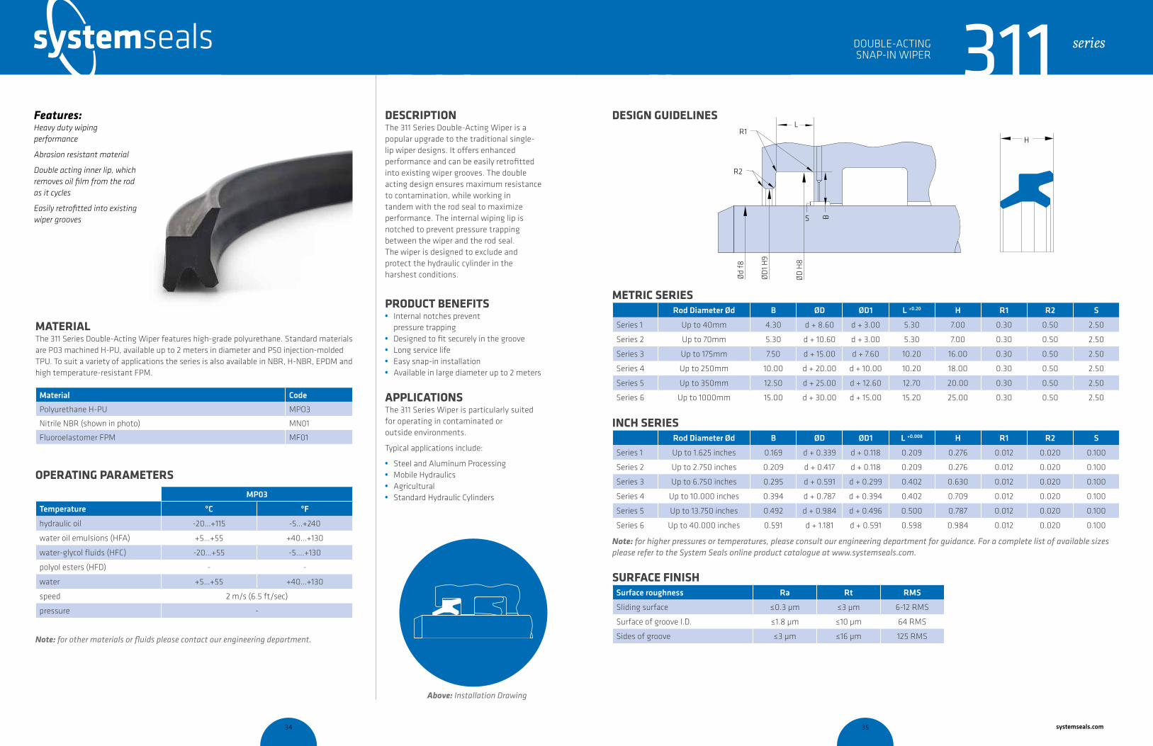
DESCRIPTION The 311 Series Double-Acting Wiper is a popular upgrade to the traditional single-lip wiper designs. It offers enhanced performance and can be easily retrofitted into existing wiper grooves. The double acting design ensures maximum resistance to contamination, while working in tandem with the rod seal to maximize performance. The internal wiping lip is notched to prevent pressure trapping between the wiper and the rod seal. The wiper is designed to exclude and protect the hydraulic cylinder in the harshest conditions.
PRODUCT BENEFITS • Internal notches prevent
pressure trapping• Designed to fit securely in the groove• Long service life• Easy snap-in installation• Available in large diameter up to 2 meters
APPLICATIONSThe 311 Series Wiper is particularly suited for operating in contaminated or outside environments.
Typical applications include:
• Steel and Aluminum Processing• Mobile Hydraulics• Agricultural• Standard Hydraulic Cylinders
MATERIAL The 311 Series Double-Acting Wiper features high-grade polyurethane. Standard materials are P03 machined H-PU, available up to 2 meters in diameter and P50 injection-molded TPU. To suit a variety of applications the series is also available in NBR, H-NBR, EPDM and high temperature-resistant FPM.
Material Code
Polyurethane H-PU MPO3
Nitrile NBR (shown in photo) MN01
Fluoroelastomer FPM MF01
OPERATING PARAMETERS
ºC MP03
Temperature ºC ºF
hydraulic oil -20…+115 -5…+240
water oil emulsions (HFA) +5…+55 +40…+130
water-glycol fluids (HFC) -20…+55 -5….+130
polyol esters (HFD) - -
water +5…+55 +40…+130
speed 2 m/s (6.5 ft/sec)
pressure -
Note: for other materials or fluids please contact our engineering department.
Above: Installation Drawing
Features: Heavy duty wiping performance
Abrasion resistant material
Double acting inner lip, which removes oil film from the rod as it cycles
Easily retrofitted into existing wiper grooves
311 seriesDOUBLE-ACTING SNAP-IN WIPER
cross-section of seal installation drawing icon
systemseals.com | 9505 Midwest Avenue, Cleveland, OH 44125 | 440.735.0200
METRIC SERIESRod Diameter Ød B ØD ØD1 L +0.20 H R1 R2 S
Series 1 Up to 40mm 4.30 d + 8.60 d + 3.00 5.30 7.00 0.30 0.50 2.50
Series 2 Up to 70mm 5.30 d + 10.60 d + 3.00 5.30 7.00 0.30 0.50 2.50
Series 3 Up to 175mm 7.50 d + 15.00 d + 7.60 10.20 16.00 0.30 0.50 2.50
Series 4 Up to 250mm 10.00 d + 20.00 d + 10.00 10.20 18.00 0.30 0.50 2.50
Series 5 Up to 350mm 12.50 d + 25.00 d + 12.60 12.70 20.00 0.30 0.50 2.50
Series 6 Up to 1000mm 15.00 d + 30.00 d + 15.00 15.20 25.00 0.30 0.50 2.50
INCH SERIESRod Diameter Ød B ØD ØD1 L +0.008 H R1 R2 S
Series 1 Up to 1.625 inches 0.169 d + 0.339 d + 0.118 0.209 0.276 0.012 0.020 0.100
Series 2 Up to 2.750 inches 0.209 d + 0.417 d + 0.118 0.209 0.276 0.012 0.020 0.100
Series 3 Up to 6.750 inches 0.295 d + 0.591 d + 0.299 0.402 0.630 0.012 0.020 0.100
Series 4 Up to 10.000 inches 0.394 d + 0.787 d + 0.394 0.402 0.709 0.012 0.020 0.100
Series 5 Up to 13.750 inches 0.492 d + 0.984 d + 0.496 0.500 0.787 0.012 0.020 0.100
Series 6 Up to 40.000 inches 0.591 d + 1.181 d + 0.591 0.598 0.984 0.012 0.020 0.100
Note: for higher pressures or temperatures, please consult our engineering department for guidance. For a complete list of available sizes please refer to the System Seals online product catalogue at www.systemseals.com.
SURFACE FINISHSurface roughness Ra Rt RMS
Sliding surface ≤0.3 µm ≤3 µm 6-12 RMS
Surface of groove I.D. ≤1.8 µm ≤10 µm 64 RMS
Sides of groove ≤3 µm ≤16 µm 125 RMS
DESIGN GUIDELINESL
R1
R2
B
H
ØD
H8
ØD
1 H9
Ød
f8
S
311 seriesDOUBLE-ACTING SNAP-IN WIPER
34 35 systemseals.com

systemseals.com | 9505 Midwest Avenue, Cleveland, OH 44125 | 440.735.0200
DESCRIPTION The 314 Series Heavy-Duty, Double-Acting Wiper is one of the most popular mill-duty wipers in the steel industry. It includes a reinforced Teflon scraper ring and two energizing O-rings. The design incorporates a wiping lip to prevent contamination from entering the cylinder and an inner sealing lip to remove any oil film from the rod as it cycles. The O-rings individually energize the two wiper lips. In most applications, a pressure relief port between the wiper and the rod seal is recommended.
PRODUCT BENEFITS • Protects the hydraulic cylinder internals • Self-lubricating • Works in short stroke applications • Works in high-temperature environments
APPLICATIONSThe 314 Series Wiper prevents contamination ingress in harsh environments, while maintaining low friction.
Typical applications include:
• Steel and Aluminum Mills • Positive and Negative Bending Cylinder • Work Roll Balance Cylinders• Injection Molding Machines• Pullback/Return Cylinders• Traverse Cylinders • Cold and Hot Strip Mills
MATERIAL The 314 Series wiper consists of a custom-blended Teflon that provides ultra-low friction and high-speed performance with minimal wear. The standard compound is Teflon with Bronze filler. The temperature range of the wiper can be increased by selecting an FPM energizer in place of the standard NBR energizer.
Material Code
PTFE-Bronze compound + NBR o-ring (shown in photo) MT23
PTFE-Bronze compound + FPM o-ring MT26
OPERATING PARAMETERS
MT23 MT26
Temperature ºC ºF ºC ºF
hydraulic oil -30... +100 -22... +212 -10... +200 -15... +392
water oil emulsions (HFA) - - - -
water-glycol fluids (HFC) - - - -
polyol esters (HFD) - - - -
water - - -10... +200 -15... +392
speed 5 m/s (16.5 ft/sec)
pressure -
Note: for other materials or fluids please contact our engineering department.
Above: Installation Drawing
Features: High-performance wiping ability
Low-friction Teflon scraper ring
Excellent wear resistance
Available in large diameter up to 2 meters
314 seriesHEAVY DUTY DOUBLE-ACTING WIPER
cross-section of seal installation drawing icon
systemseals.com | 9505 Midwest Avenue, Cleveland, OH 44125 | 440.735.0200
METRIC SERIESRod Diameter Ød B ØD ØD1 L +0.2 R n S
Series 1 up to 45 mm 3.80 d+7.60 d+1.00 4.20 0.40 4.00 2.50
Series 2 up to 70 mm 4.40 d+8.80 d+1.50 6.30 1.20 4.00 2.50
Series 3 up to 140 mm 6.10 d+12.20 d+2.00 8.10 2.00 4.00 2.50
Series 4 up to 400 mm 8.00 d+16.00 d+2.00 11.50 2.00 4.00 2.50
Series 5 up to 650 mm 12.00 d+24.00 d+2.50 15.50 2.00 4.00 2.50
Series 6 up to 1000 mm 13.65 d+27.30 d+2.50 18.00 2.00 5.00 2.50
INCH SERIESRod Diameter Ød B ØD ØD1 L +0.008 R n S
Series 1 up to 1.75 in 0.150 d+0.300 d+0.040 0.165 0.015 0.160 0.100
Series 2 up to 2.75 in 0.173 d+0.346 d+0.060 0.248 0.050 0.160 0.100
Series 3 up to 5.50 in 0.240 d+0.480 d+0.080 0.319 0.080 0.160 0.100
Series 4 up to 15.75 in 0.315 d+0.630 d+0.080 0.453 0.080 0.160 0.100
Series 5 up to 25.5 in 0.472 d+0.944 d+0.100 0.610 0.080 0.160 0.100
Series 6 up to 40.0 in 0.537 d+1.074 d+0.100 0.709 0.080 0.200 0.100Note: For a complete list of available sizes please refer to the System Seals online product catalogue at www.systemseals.com.
SURFACE FINISHSurface roughness Ra Rt RMS
Sliding surface ≤0.3 µm ≤3 µm 8 RMS
Surface of groove I.D. ≤1.8 µm ≤10 µm 64 RMS
Sides of groove ≤3 µm ≤16 µm 125 RMS
DESIGN GUIDELINESn/2
45o
n
L
R
B
Ød
f8
ØD
H9
ØD
1 H10
rounded &burr free
S
HEAVY DUTY DOUBLE-ACTING WIPER 314 series
36 37 systemseals.com

systemseals.com | 9505 Midwest Avenue, Cleveland, OH 44125 | 440.735.0200
DESCRIPTION The 315 Series Heavy-Duty, Double-Acting Wiper is one of the most popular heavy-duty wipers. It includes a reinforced Teflon scraper ring and one energizing O-ring. The design incorporates a wiping lip to prevent contamination from entering the cylinder and an inner sealing lip to remove any oil film from the rod as it cycles. The O-ring energizes the two wiper lips. In most applications, a pressure relief port between the wiper and the rod seal is recommended.
PRODUCT BENEFITS • Protects the hydraulic cylinder internals • Self-lubricating • Works in short stroke applications • Works in high-temperature environments
APPLICATIONSThe 315 Series Wiper prevents contamination ingress in harsh environments, while maintaining low friction.
Typical applications include:
• Forging Presses• Extrusion Presses • Stamping Presses• Steel and Aluminum Mills • Injection Molding Machines• Cold and Hot Strip Mills
MATERIAL The 315 Series wiper consists of a custom-blended Teflon that provides ultra-low friction and high-speed performance with minimal wear. The standard compound is Teflon with Bronze filler. The temperature range of the wiper can be increased by selecting an FPM energizer in place of the standard NBR energizer.
Material Code
PTFE-Bronze compound + NBR o-ring (shown in photo) MT23
PTFE-Bronze compound + FPM o-ring MT26
OPERATING PARAMETERS
MT23 MT26
Temperature ºC ºF ºC ºF
hydraulic oil -30... +100 -22... +212 -10... +200 -15... +392
water oil emulsions (HFA) - - - -
water-glycol fluids (HFC) - - - -
polyol esters (HFD) - - - -
water - - -10... +200 -15... +392
speed 5 m/s (16.5 ft/sec)
pressure -
Note: for other materials or fluids please contact our engineering department.
Above: Installation Drawing
Features: High-performance wiping ability
Low-friction Teflon scraper ring
Excellent wear resistance
Available in large diameter up to 2 meters
315 seriesDOUBLE-ACTING SNAP-IN WIPER
cross-section of seal installation drawing icon
systemseals.com | 9505 Midwest Avenue, Cleveland, OH 44125 | 440.735.0200
METRIC SERIESØd B ØD ØD1 L+0.2 R n S
Series 1 up to 45 mm 3.80 d+7.60 d+1.00 4.20 0.40 4.00 2.50
Series 2 up to 70 mm 4.40 d+8.80 d+1.50 6.30 1.20 4.00 2.50
Series 3 up to 140 mm 6.10 d+12.20 d+2.00 8.10 2.00 4.00 2.50
Series 4 up to 400 mm 8.00 d+16.00 d+2.00 11.50 2.00 4.00 2.50
Series 5 up to 650 mm 12.00 d+24.00 d+2.50 15.50 2.00 4.00 2.50
Series 6 up to 1000 mm 13.65 d+27.30 d+2.50 18.00 2.00 5.00 2.50
INCH SERIESØd B ØD ØD1 L+0.008 R n S
Series 1 up to 1.75 in 0.150 d+0.300 d+0.040 0.165 0.015 0.160 0.100
Series 2 up to 2.75 in 0.173 d+0.346 d+0.060 0.248 0.050 0.160 0.100
Series 3 up to 5.50 in 0.240 d+0.480 d+0.080 0.319 0.080 0.160 0.100
Series 4 up to 15.75 in 0.315 d+0.630 d+0.080 0.453 0.080 0.160 0.100
Series 5 up to 25.5 in 0.472 d+0.944 d+0.100 0.610 0.080 0.160 0.100
Series 6 up to 40.0 in 0.537 d+1.074 d+0.100 0.709 0.080 0.200 0.100
Note: For higher pressures or temperatures, please consult our engineering department for guidance. For a complete list of available sizes please refer to the System Seals online product catalogue at www.systemseals.com.
SURFACE FINISHSurface roughness Ra Rt RMS
Sliding surface ≤0.3 µm ≤3 µm 8 RMS
Surface of groove I.D. ≤1.8 µm ≤10 µm 64 RMS
Sides of groove ≤3 µm ≤16 µm 125 RMS
DESIGN GUIDELINES
n/2
45o
n
L
R
B
Ød
f8
ØD
H9
ØD
1 H10
rounded &burr free
S
315 seriesDOUBLE-ACTING SNAP-IN WIPER
38 39 systemseals.com

systemseals.com | 9505 Midwest Avenue, Cleveland, OH 44125 | 440.735.0200
METRIC SERIESRod Diameter Ød B ØD ØD1 L +0.2 L1 -0.10 R1 R2 S
Series 1 up to 40 mm 3.00 d+6.00 d+3.75 3.00 1.00 0.30 0.50 2.50
Series 2 up to 50 mm 5.00 d+10.00 d+5.75 5.00 1.50 0.30 0.50 2.50
Series 3 up to 90 mm 6.50 d+13.00 d+7.50 6.50 2.00 0.30 0.50 2.50
Series 4 up to 115 mm 8.00 d+16.00 d+9.10 8.00 3.00 0.30 0.50 2.50
Series 5 up to 175 mm 10.00 d+20.00 d+11.25 10.00 4.00 0.30 0.50 2.50
Series 6 up to 1000 mm 12.50 d+25.00 d+15.00 12.50 5.00 0.30 0.50 2.50
INCH SERIESRod Diameter Ød B ØD ØD1 L +0.008 L1 +0.004 R1 R2 S
Series 1 up to 1.625 in 0.125 d+0.250 d+0.148 0.125 0.040 0.012 0.020 0.100
Series 2 up to 1.875 in 0.188 d+0.376 d+0.222 0.188 0.060 0.012 0.020 0.100
Series 3 up to 3.500 in 0.250 d+0.500 d+0.296 0.250 0.080 0.012 0.020 0.100
Series 4 up to 4.375 in 0.313 d+0.626 d+0.358 0.313 0.118 0.012 0.020 0.100
Series 5 up to 6.750 in 0.375 d+0.750 d+0.442 0.375 0.158 0.012 0.020 0.100
Series 6 up to 40.000 in 0.500 d+1.000 d+0.590 0.500 0.197 0.012 0.020 0.100
Note: for a complete list of available sizes please refer to the System Seals online product catalogue at www.systemseals.com.
SURFACE FINISHSurface roughness Ra Rt RMS
Sliding surface ≤0.3 µm ≤3 µm 8 RMS
Surface of groove I.D. ≤1.8 µm ≤10 µm 64 RMS
Sides of groove ≤3 µm ≤16 µm 125 RMS
DESIGN GUIDELINES L
R1
R2
L1
ØD
H8
ØD
1 H
9
Ød
f8
S B
317 seriesMILL-DUTY, DOUBLE-ACTING WIPER
systemseals.com | 9505 Midwest Avenue, Cleveland, OH 44125 | 440.735.0200
DESCRIPTION The 317 Series Mill-Duty, Double-Acting Wiper is a new design that is water resistant and eliminates internal corrosion associated with other designs. The aggressive profile includes a unique umbrella feature that wraps around the face of the cylinder to create an impenetrable barrier. It works particularly well in vertically mounted cylinders, where contamination collects or fluid splashes on top of the cylinder. The wiper is designed to exclude and protect the hydraulic cylinder in the harshest conditions.
PRODUCT BENEFITS • Internal notches prevent
pressure trapping• Designed to fit securely in the groove• Long service life• Easy snap-in installation• Available in large diameter up to 2 meters
APPLICATIONSThe 317 Series Wiper is used in severely contaminated, wet and abrasive conditions.
Typical applications include:
• Steel and Aluminum Processing• Cold and Hot Strip Mills• Automatic Gauge Control Cylinders
MATERIAL The 317 Series Double-Acting Wiper features N76, a high-grade abrasion-resistant elastomer.
Material Code
Polyurethane H-PU (shown in photo) MPO3
Nitrile NBR MN01
Hydrogenated NBR MN03
Fluoroelastomer FPM MF01
OPERATING PARAMETERS
MP03
Temperature ºC ºF
hydraulic oil -20…+115 -5…+240
water oil emulsions (HFA) +5…+55 +40…+130
water-glycol fluids (HFC) -20…+55 -5….+130
polyol esters (HFD) - -
water +5…+55 +40…+130
speed 2 m/s (6.5 ft/sec)
pressure -
Note: for other materials or fluids please contact our engineering department.
Above: Installation Drawing
Features: Aggressive wiping and high scraping performance
Abrasion resistant
Unique umbrella design ensures maximum exclusion
Double acting inner lip, which removes oil film from the rod as it cycles
Water resistant
317 seriesMILL-DUTY, DOUBLE-ACTING WIPER
cross-section of seal installation drawing icon
40 41 systemseals.com
systemseals.com | 9505 Midwest Avenue, Cleveland, OH 44125 | 440.735.0200
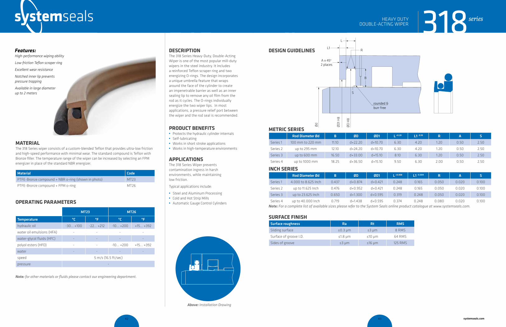
DESCRIPTION The 318 Series Heavy-Duty, Double-Acting Wiper is one of the most popular mill-duty wipers in the steel industry. It includes a reinforced Teflon scraper ring and two energizing O-rings. The design incorporates a unique umbrella feature that wraps around the face of the cylinder to create an impenetrable barrier as well as an inner sealing lip to remove any oil film from the rod as it cycles. The O-rings individually energize the two wiper lips. In most applications, a pressure relief port between the wiper and the rod seal is recommended.
PRODUCT BENEFITS • Protects the hydraulic cylinder internals • Self-lubricating • Works in short stroke applications • Works in high-temperature environments
APPLICATIONSThe 318 Series Wiper prevents contamination ingress in harsh environments, while maintaining low friction.
Typical applications include:
• Steel and Aluminum Processing• Cold and Hot Strip Mills• Automatic Gauge Control Cylinders
MATERIAL The 318 Series wiper consists of a custom-blended Teflon that provides ultra-low friction and high-speed performance with minimal wear. The standard compound is Teflon with Bronze filler. The temperature range of the wiper can be increased by selecting an FPM energizer in place of the standard NBR energizer.
Material Code
PTFE-Bronze compound + NBR o-ring (shown in photo) MT23
PTFE-Bronze compound + FPM o-ring MT26
OPERATING PARAMETERS
MT23 MT26
Temperature ºC ºF ºC ºF
hydraulic oil -30... +100 -22... +212 -10... +200 +15... +392
water oil emulsions (HFA) - - - -
water-glycol fluids (HFC) - - - -
polyol esters (HFD) - - -10... +200 +15... +392
water - - - -
speed 5 m/s (16.5 ft/sec)
pressure -
Note: for other materials or fluids please contact our engineering department.
Above: Installation Drawing
Features: High-performance wiping ability
Low-friction Teflon scraper ring
Excellent wear resistance
Notched inner lip prevents pressure trapping
Available in large diameter up to 2 meters
HEAVY DUTY DOUBLE-ACTING WIPER
cross-section of seal installation drawing icon
318series
systemseals.com | 9505 Midwest Avenue, Cleveland, OH 44125 | 440.735.0200
METRIC SERIESRod Diameter Ød B ØD ØD1 L +0.20 L1 -0.10 R A S
Series 1 100 mm to 220 mm 11.10 d+22.20 d+10.70 6.30 4.20 1.20 0.50 2.50
Series 2 up to 295 mm 12.10 d+24.20 d+10.70 6.30 4.20 1.20 0.50 2.50
Series 3 up to 600 mm 16.50 d+33.00 d+15.10 8.10 6.30 1.20 0.50 2.50
Series 4 up to 1000 mm 18.25 d+36.50 d+15.10 9.50 6.30 2.00 0.50 2.50
INCH SERIESRod Diameter Ød B ØD ØD1 L +0.008 L1 -0.004 R A S
Series 1 4.000 to 8.625 Inch 0.437 d+0.874 d+0.421 0.248 0.165 0.050 0.020 0.100
Series 2 up to 11.625 Inch 0.476 d+0.952 d+0.421 0.248 0.165 0.050 0.020 0.100
Series 3 up to 23.625 Inch 0.650 d+1.300 d+0.595 0.319 0.248 0.050 0.020 0.100
Series 4 up to 40.000 Inch 0.719 d+1.438 d+0.595 0.374 0.248 0.080 0.020 0.100Note: For a complete list of available sizes please refer to the System Seals online product catalogue at www.systemseals.com.
SURFACE FINISHSurface roughness Ra Rt RMS
Sliding surface ≤0.3 µm ≤3 µm 8 RMS
Surface of groove I.D. ≤1.8 µm ≤10 µm 64 RMS
Sides of groove ≤3 µm ≤16 µm 125 RMS
DESIGN GUIDELINES
A x 45o
2 places
L1
L
R
Ød
ØD
H8
ØD
1 H8
B
rounded &burr free
B
S
HEAVY DUTY DOUBLE-ACTING WIPER 318series
42 43 systemseals.com
systemseals.com | 9505 Midwest Avenue, Cleveland, OH 44125 | 440.735.0200
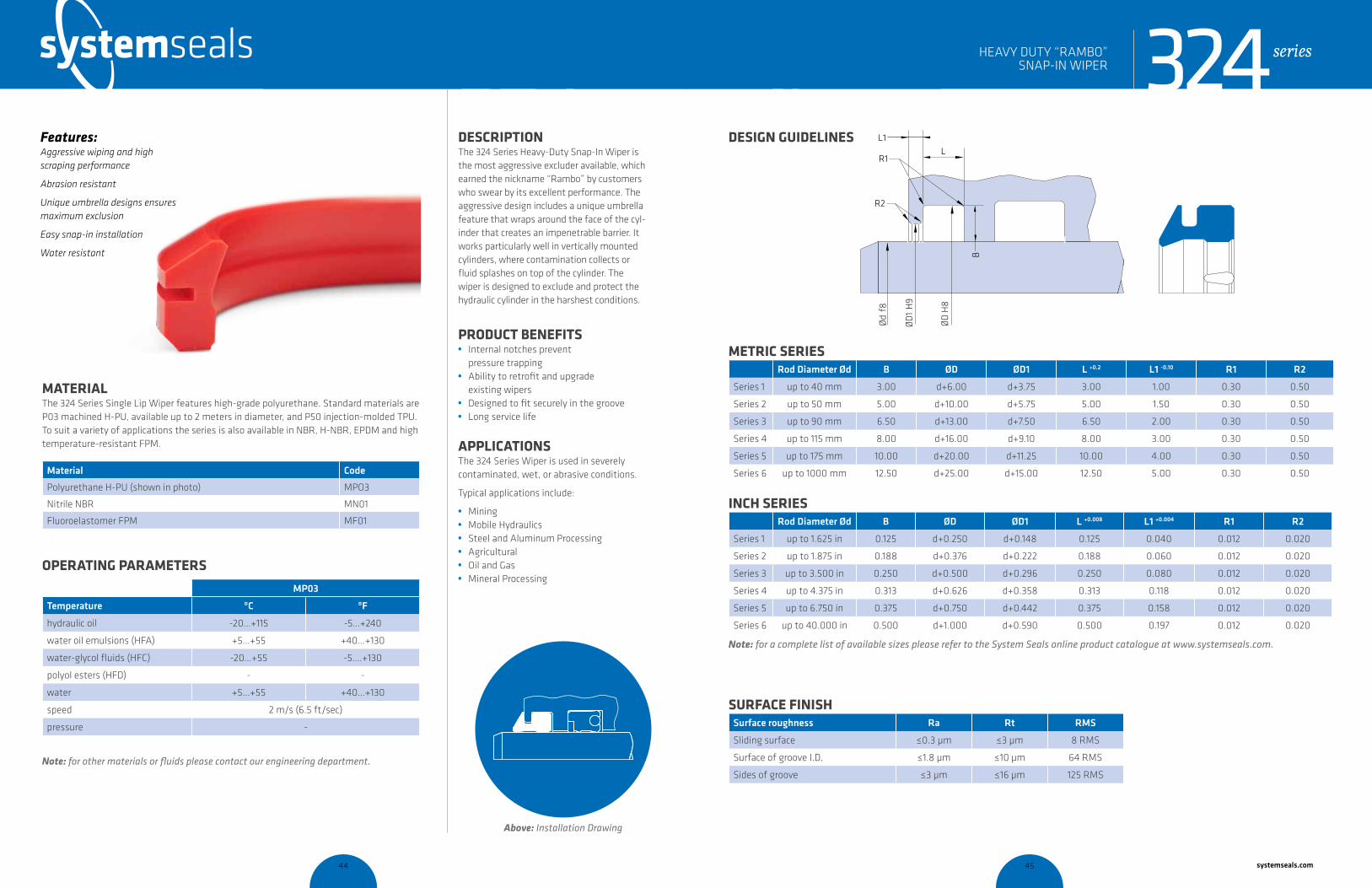
DESCRIPTION The 324 Series Heavy-Duty Snap-In Wiper is the most aggressive excluder available, which earned the nickname “Rambo” by customers who swear by its excellent performance. The aggressive design includes a unique umbrella feature that wraps around the face of the cyl-inder that creates an impenetrable barrier. It works particularly well in vertically mounted cylinders, where contamination collects or fluid splashes on top of the cylinder. The wiper is designed to exclude and protect the hydraulic cylinder in the harshest conditions.
PRODUCT BENEFITS • Internal notches prevent
pressure trapping• Ability to retrofit and upgrade
existing wipers• Designed to fit securely in the groove• Long service life
APPLICATIONSThe 324 Series Wiper is used in severely contaminated, wet, or abrasive conditions.
Typical applications include:
• Mining • Mobile Hydraulics• Steel and Aluminum Processing• Agricultural• Oil and Gas• Mineral Processing
MATERIAL The 324 Series Single Lip Wiper features high-grade polyurethane. Standard materials are P03 machined H-PU, available up to 2 meters in diameter, and P50 injection-molded TPU. To suit a variety of applications the series is also available in NBR, H-NBR, EPDM and high temperature-resistant FPM.
Material Code
Polyurethane H-PU (shown in photo) MPO3
Nitrile NBR MN01
Fluoroelastomer FPM MF01
OPERATING PARAMETERS
MP03
Temperature ºC ºF
hydraulic oil -20…+115 -5…+240
water oil emulsions (HFA) +5…+55 +40…+130
water-glycol fluids (HFC) -20…+55 -5….+130
polyol esters (HFD) - -
water +5…+55 +40…+130
speed 2 m/s (6.5 ft/sec)
pressure -
Note: for other materials or fluids please contact our engineering department.
Above: Installation Drawing
Features: Aggressive wiping and high scraping performance
Abrasion resistant
Unique umbrella designs ensures maximum exclusion
Easy snap-in installation
Water resistant
324seriesHEAVY DUTY “RAMBO” SNAP-IN WIPER
cross-section of seal installation drawing icon
systemseals.com | 9505 Midwest Avenue, Cleveland, OH 44125 | 440.735.0200
METRIC SERIESRod Diameter Ød B ØD ØD1 L +0.2 L1 -0.10 R1 R2
Series 1 up to 40 mm 3.00 d+6.00 d+3.75 3.00 1.00 0.30 0.50
Series 2 up to 50 mm 5.00 d+10.00 d+5.75 5.00 1.50 0.30 0.50
Series 3 up to 90 mm 6.50 d+13.00 d+7.50 6.50 2.00 0.30 0.50
Series 4 up to 115 mm 8.00 d+16.00 d+9.10 8.00 3.00 0.30 0.50
Series 5 up to 175 mm 10.00 d+20.00 d+11.25 10.00 4.00 0.30 0.50
Series 6 up to 1000 mm 12.50 d+25.00 d+15.00 12.50 5.00 0.30 0.50
INCH SERIESRod Diameter Ød B ØD ØD1 L +0.008 L1 +0.004 R1 R2
Series 1 up to 1.625 in 0.125 d+0.250 d+0.148 0.125 0.040 0.012 0.020
Series 2 up to 1.875 in 0.188 d+0.376 d+0.222 0.188 0.060 0.012 0.020
Series 3 up to 3.500 in 0.250 d+0.500 d+0.296 0.250 0.080 0.012 0.020
Series 4 up to 4.375 in 0.313 d+0.626 d+0.358 0.313 0.118 0.012 0.020
Series 5 up to 6.750 in 0.375 d+0.750 d+0.442 0.375 0.158 0.012 0.020
Series 6 up to 40.000 in 0.500 d+1.000 d+0.590 0.500 0.197 0.012 0.020
Note: for a complete list of available sizes please refer to the System Seals online product catalogue at www.systemseals.com.
SURFACE FINISHSurface roughness Ra Rt RMS
Sliding surface ≤0.3 µm ≤3 µm 8 RMS
Surface of groove I.D. ≤1.8 µm ≤10 µm 64 RMS
Sides of groove ≤3 µm ≤16 µm 125 RMS
DESIGN GUIDELINES L1L
R1
R2
B
Ød
f8
ØD
1 H
9
ØD
H8
324seriesHEAVY DUTY “RAMBO” SNAP-IN WIPER
44 45 systemseals.com
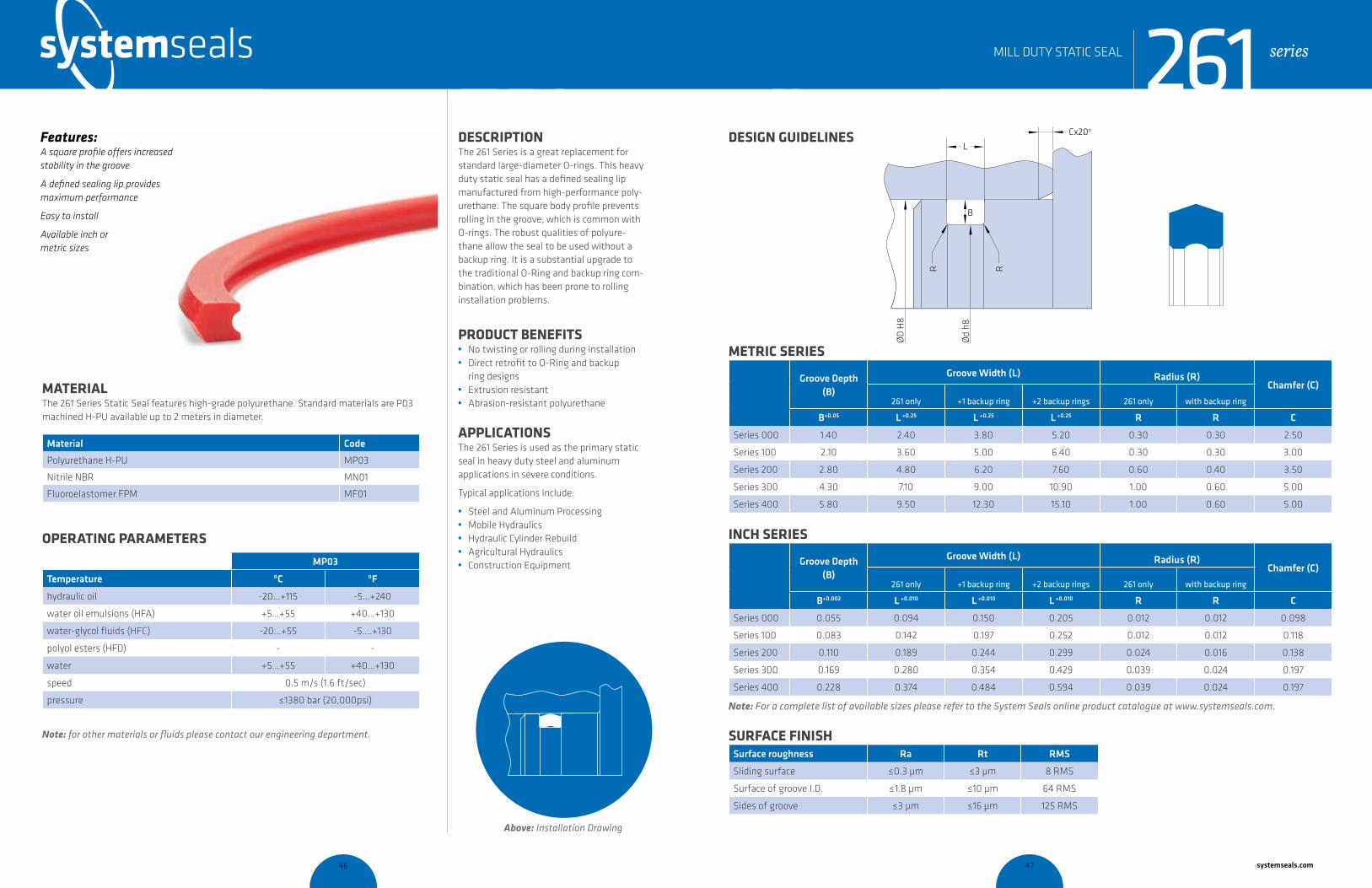
systemseals.com | 9505 Midwest Avenue, Cleveland, OH 44125 | 440.735.0200
DESCRIPTION The 261 Series is a great replacement for standard large-diameter O-rings. This heavy duty static seal has a defined sealing lip manufactured from high-performance poly-urethane. The square body profile prevents rolling in the groove, which is common with O-rings. The robust qualities of polyure-thane allow the seal to be used without a backup ring. It is a substantial upgrade to the traditional O-Ring and backup ring com-bination, which has been prone to rolling installation problems.
PRODUCT BENEFITS • No twisting or rolling during installation• Direct retrofit to O-Ring and backup
ring designs• Extrusion resistant • Abrasion-resistant polyurethane
APPLICATIONSThe 261 Series is used as the primary static seal in heavy duty steel and aluminum applications in severe conditions.
Typical applications include:
• Steel and Aluminum Processing • Mobile Hydraulics• Hydraulic Cylinder Rebuild• Agricultural Hydraulics• Construction Equipment
MATERIAL The 261 Series Static Seal features high-grade polyurethane. Standard materials are P03 machined H-PU available up to 2 meters in diameter.
Material Code
Polyurethane H-PU MP03
Nitrile NBR MN01
Fluoroelastomer FPM MF01
OPERATING PARAMETERS
MP03
Temperature ºC ºF
hydraulic oil -20…+115 -5…+240
water oil emulsions (HFA) +5…+55 +40…+130
water-glycol fluids (HFC) -20…+55 -5….+130
polyol esters (HFD) - -
water +5…+55 +40…+130
speed 0.5 m/s (1.6 ft/sec)
pressure ≤1380 bar (20,000psi)
Note: for other materials or fluids please contact our engineering department.
Above: Installation Drawing
Features: A square profile offers increased stability in the groove
A defined sealing lip provides maximum performance
Easy to install
Available inch or metric sizes
series
cross-section of seal installation drawing icon
261MILL DUTY STATIC SEAL
systemseals.com | 9505 Midwest Avenue, Cleveland, OH 44125 | 440.735.0200
METRIC SERIES
Groove Depth (B)
Groove Width (L) Radius (R)Chamfer (C)
261 only +1 backup ring +2 backup rings 261 only with backup ring
B+0.05 L +0.25 L +0.25 L +0.25 R R C
Series 000 1.40 2.40 3.80 5.20 0.30 0.30 2.50
Series 100 2.10 3.60 5.00 6.40 0.30 0.30 3.00
Series 200 2.80 4.80 6.20 7.60 0.60 0.40 3.50
Series 300 4.30 7.10 9.00 10.90 1.00 0.60 5.00
Series 400 5.80 9.50 12.30 15.10 1.00 0.60 5.00
INCH SERIES
Groove Depth (B)
Groove Width (L) Radius (R)Chamfer (C)
261 only +1 backup ring +2 backup rings 261 only with backup ring
B+0.002 L +0.010 L +0.010 L +0.010 R R C
Series 000 0.055 0.094 0.150 0.205 0.012 0.012 0.098
Series 100 0.083 0.142 0.197 0.252 0.012 0.012 0.118
Series 200 0.110 0.189 0.244 0.299 0.024 0.016 0.138
Series 300 0.169 0.280 0.354 0.429 0.039 0.024 0.197
Series 400 0.228 0.374 0.484 0.594 0.039 0.024 0.197
Note: For a complete list of available sizes please refer to the System Seals online product catalogue at www.systemseals.com.
SURFACE FINISHSurface roughness Ra Rt RMS
Sliding surface ≤0.3 µm ≤3 µm 8 RMS
Surface of groove I.D. ≤1.8 µm ≤10 µm 64 RMS
Sides of groove ≤3 µm ≤16 µm 125 RMS
DESIGN GUIDELINESL
B
ØD
H8
Ød
h8
R R
Cx20o
series261MILL DUTY STATIC SEAL
46 47 systemseals.com
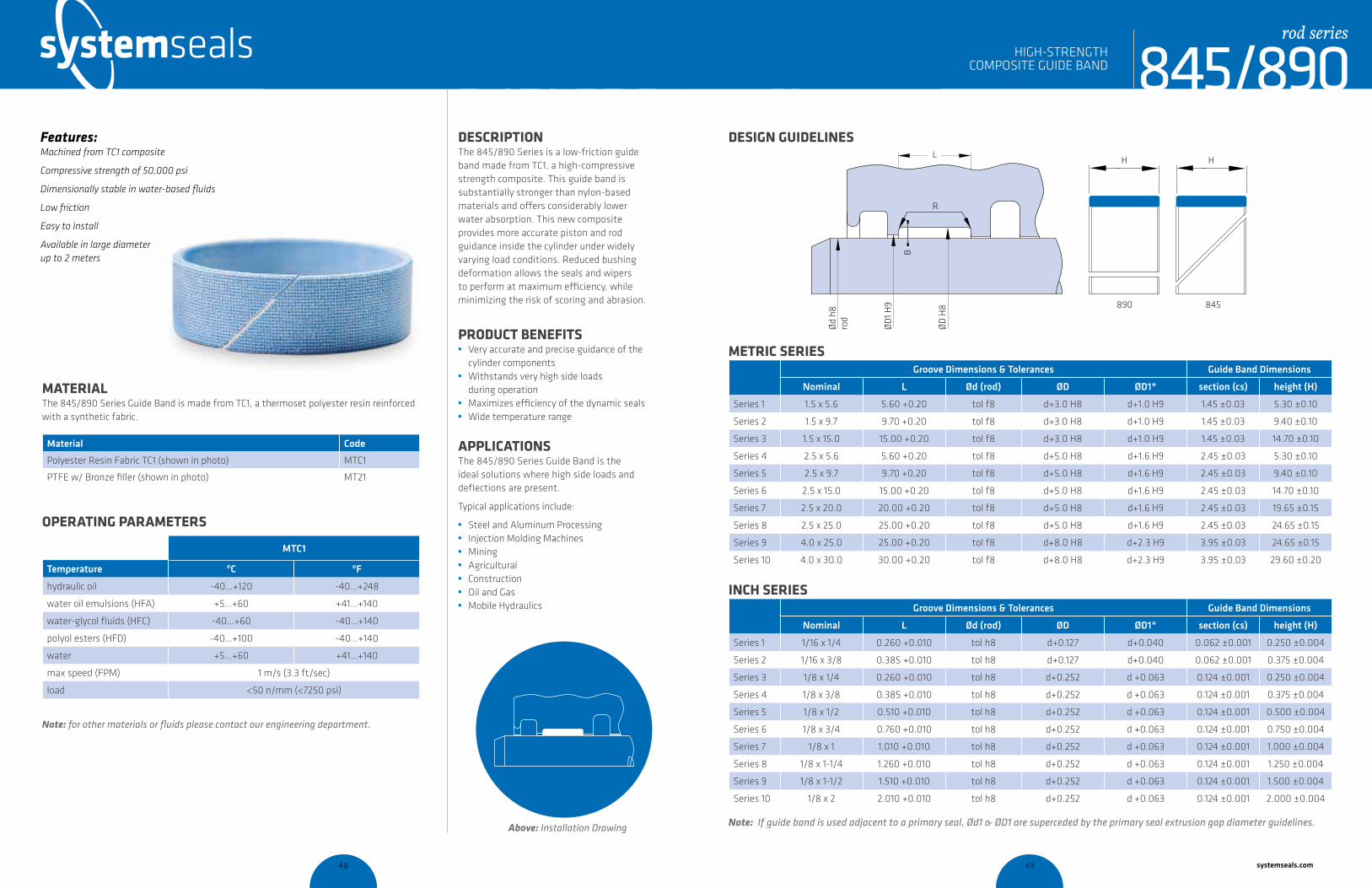
systemseals.com | 9505 Midwest Avenue, Cleveland, OH 44125 | 440.735.0200
DESCRIPTION The 845/890 Series is a low-friction guide band made from TC1, a high-compressive strength composite. This guide band is substantially stronger than nylon-based materials and offers considerably lower water absorption. This new composite provides more accurate piston and rod guidance inside the cylinder under widely varying load conditions. Reduced bushing deformation allows the seals and wipers to perform at maximum efficiency, while minimizing the risk of scoring and abrasion.
PRODUCT BENEFITS • Very accurate and precise guidance of the
cylinder components• Withstands very high side loads
during operation• Maximizes efficiency of the dynamic seals• Wide temperature range
APPLICATIONSThe 845/890 Series Guide Band is the ideal solutions where high side loads and deflections are present.
Typical applications include:
• Steel and Aluminum Processing • Injection Molding Machines• Mining• Agricultural• Construction• Oil and Gas• Mobile Hydraulics
MATERIAL The 845/890 Series Guide Band is made from TC1, a thermoset polyester resin reinforced with a synthetic fabric.
Material Code
Polyester Resin Fabric TC1 (shown in photo) MTC1
PTFE w/ Bronze filler (shown in photo) MT21
OPERATING PARAMETERS
MTC1
Temperature ºC ºF
hydraulic oil -40…+120 -40…+248
water oil emulsions (HFA) +5…+60 +41…+140
water-glycol fluids (HFC) -40…+60 -40…+140
polyol esters (HFD) -40…+100 -40…+140
water +5…+60 +41…+140
max speed (FPM) 1 m/s (3.3 ft/sec)
load <50 n/mm (<7250 psi)
Note: for other materials or fluids please contact our engineering department.
Above: Installation Drawing
Features: Machined from TC1 composite
Compressive strength of 50,000 psi
Dimensionally stable in water-based fluids
Low friction
Easy to install
Available in large diameter up to 2 meters
cross-section of seal installation drawing icon
845/890rod series
HIGH-STRENGTH COMPOSITE GUIDE BAND
systemseals.com | 9505 Midwest Avenue, Cleveland, OH 44125 | 440.735.0200
METRIC SERIESGroove Dimensions & Tolerances Guide Band Dimensions
Nominal L Ød (rod) ØD ØD1* section (cs) height (H)
Series 1 1.5 x 5.6 5.60 +0.20 tol f8 d+3.0 H8 d+1.0 H9 1.45 ±0.03 5.30 ±0.10
Series 2 1.5 x 9.7 9.70 +0.20 tol f8 d+3.0 H8 d+1.0 H9 1.45 ±0.03 9.40 ±0.10
Series 3 1.5 x 15.0 15.00 +0.20 tol f8 d+3.0 H8 d+1.0 H9 1.45 ±0.03 14.70 ±0.10
Series 4 2.5 x 5.6 5.60 +0.20 tol f8 d+5.0 H8 d+1.6 H9 2.45 ±0.03 5.30 ±0.10
Series 5 2.5 x 9.7 9.70 +0.20 tol f8 d+5.0 H8 d+1.6 H9 2.45 ±0.03 9.40 ±0.10
Series 6 2.5 x 15.0 15.00 +0.20 tol f8 d+5.0 H8 d+1.6 H9 2.45 ±0.03 14.70 ±0.10
Series 7 2.5 x 20.0 20.00 +0.20 tol f8 d+5.0 H8 d+1.6 H9 2.45 ±0.03 19.65 ±0.15
Series 8 2.5 x 25.0 25.00 +0.20 tol f8 d+5.0 H8 d+1.6 H9 2.45 ±0.03 24.65 ±0.15
Series 9 4.0 x 25.0 25.00 +0.20 tol f8 d+8.0 H8 d+2.3 H9 3.95 ±0.03 24.65 ±0.15
Series 10 4.0 x 30.0 30.00 +0.20 tol f8 d+8.0 H8 d+2.3 H9 3.95 ±0.03 29.60 ±0.20
INCH SERIESGroove Dimensions & Tolerances Guide Band Dimensions
Nominal L Ød (rod) ØD ØD1* section (cs) height (H)
Series 1 1/16 x 1/4 0.260 +0.010 tol h8 d+0.127 d+0.040 0.062 ±0.001 0.250 ±0.004
Series 2 1/16 x 3/8 0.385 +0.010 tol h8 d+0.127 d+0.040 0.062 ±0.001 0.375 ±0.004
Series 3 1/8 x 1/4 0.260 +0.010 tol h8 d+0.252 d +0.063 0.124 ±0.001 0.250 ±0.004
Series 4 1/8 x 3/8 0.385 +0.010 tol h8 d+0.252 d +0.063 0.124 ±0.001 0.375 ±0.004
Series 5 1/8 x 1/2 0.510 +0.010 tol h8 d+0.252 d +0.063 0.124 ±0.001 0.500 ±0.004
Series 6 1/8 x 3/4 0.760 +0.010 tol h8 d+0.252 d +0.063 0.124 ±0.001 0.750 ±0.004
Series 7 1/8 x 1 1.010 +0.010 tol h8 d+0.252 d +0.063 0.124 ±0.001 1.000 ±0.004
Series 8 1/8 x 1-1/4 1.260 +0.010 tol h8 d+0.252 d +0.063 0.124 ±0.001 1.250 ±0.004
Series 9 1/8 x 1-1/2 1.510 +0.010 tol h8 d+0.252 d +0.063 0.124 ±0.001 1.500 ±0.004
Series 10 1/8 x 2 2.010 +0.010 tol h8 d+0.252 d +0.063 0.124 ±0.001 2.000 ±0.004
DESIGN GUIDELINESL
890 845
Ød
h8
ØD
1 H9
ØD
H8
R
B
rod
H H
HIGH-STRENGTH COMPOSITE GUIDE BAND 845/890
rod series
Note: If guide band is used adjacent to a primary seal, Ød1 & ØD1 are superceded by the primary seal extrusion gap diameter guidelines.
48 49 systemseals.com

systemseals.com | 9505 Midwest Avenue, Cleveland, OH 44125 | 440.735.0200
DESCRIPTION The 845/890 Series is a low-friction guide band made from TC1, a high-compressive strength composite. This guide band is substantially stronger than nylon-based materials and offers considerably lower water absorption. This new composite provides more accurate piston and rod guidance inside the cylinder under widely varying load conditions. Reduced bushing deformation allows the seals and wipers to perform at maximum efficiency, while minimizing the risk of scoring and abrasion.
PRODUCT BENEFITS • Very accurate and precise guidance of the
cylinder components• Withstands very high side loads during
operation• Maximizes efficiency of the dynamic seals• Wide temperature range
APPLICATIONSThe 845/890 Series Guide Band is the ideal solutions where high side loads and deflections are present.
Typical applications include:
• Steel and Aluminum Processing • Injection Molding Machines• Mining• Agricultural• Construction• Oil and Gas• Mobile Hydraulics
MATERIAL The 845/890 Series Guide Band is made from TC1, a thermoset polyester resin reinforced with a synthetic fabric.
Material Code
Polyester Resin Fabric TC1 (shown in photo) MTC1
PTFE w/ Bronze filler (shown in photo) MT21
OPERATING PARAMETERS
MTC1
Temperature ºC ºF
hydraulic oil -40…+120 -40…+248
water oil emulsions (HFA) +5…+60 +41…+140
water-glycol fluids (HFC) -40…+60 -40…+140
polyol esters (HFD) -40…+100 -40…+140
water +5…+60 +41…+140
max speed (FPM) 1 m/s (3.3 ft/sec)
load <50 n/mm (<7250 psi)
Note: for other materials or fluids please contact our engineering department.
Above: Installation Drawingcross-section of seal installation drawing icon
845/890piston series
HIGH-STRENGTH COMPOSITE GUIDE BAND
Features: Machined from TC1 composite
Compressive strength of 50,000 psi
Dimensionally stable in water-based fluids
Low friction
Easy to install
Available in large diameter up to 2 meters
systemseals.com | 9505 Midwest Avenue, Cleveland, OH 44125 | 440.735.0200
DESIGN GUIDELINES
bore
L
B
R
ØD
H8
Ød
h8
ØD
1 h9 890 845
H H
HIGH-STRENGTH COMPOSITE GUIDE BAND 845/890
piston series
METRIC SERIESGroove Dimensions & Tolerances Guide Band Dimensions
Nominal L ØD (bore) Ød Ød1* section (cs) height (H)
Series 1 1.5x 5.6 5.60 +0.20 tol H8 D-3.0 h8 D-1.0 h9 1.45 ±0.03 5.30 ±0.10
Series 2 1.5 x 9.7 9.70 +0.20 tol H8 D-3.0 h8 D-1.0 h9 1.45 ±0.03 9.40 ±0.10
Series 3 1.5 x 15.0 15.00 +0.20 tol H8 D-3.0 h8 D-1.0 h9 1.45 ±0.03 14.70 ±0.10
Series 4 2.5 x 5.6 5.60 +0.20 tol H8 D-5.0 h8 D-1.6 h9 2.45 ±0.03 5.30 ±0.10
Series 5 2.5 x 9.7 9.70 +0.20 tol H8 D-5.0 h8 D-1.6 h9 2.45 ±0.03 9.40 ±0.10
Series 6 2.5 x 15.0 15.00 +0.20 tol H8 D-5.0 h8 D-1.6 h9 2.45 ±0.03 14.70 ±0.10
Series 7 2.5 x 20.0 20.00 +0.20 tol H8 D-5.0 h8 D-1.6 h9 2.45 ±0.03 19.65 ±0.15
Series 8 2.5 x 25.0 25.00 +0.20 tol H8 D-5.0 h8 D-1.6 h9 2.45 ±0.03 24.65 ±0.15
Series 9 4.0 x 25.0 25.00 +0.20 tol H8 D-8.0 h8 D-2.3 h9 3.95 ±0.03 24.65 ±0.15
Series 10 4.0 x 30.0 30.00 +0.20 tol H8 D-8.0 h8 D-2.3 h9 3.95 ±0.03 29.60 ±0.20
INCH SERIESGroove Dimensions & Tolerances Guide Band Dimensions
Nominal L ØD (bore) Ød Ød1* section (cs) height (H)
Series 1 1/16 x 1/4 0.260+0.010 tol H8 D-0.127 D-0.040 0.062 ±0.001 0.250 ±0.004
Series 2 1/16 x 3/8 0.385+0.010 tol H8 D-0.127 D-0.040 0.062 ±0.001 0.375 ±0.004
Series 3 1/8 x 1/4 0.260+0.010 tol H8 D-0.252 D-0.063 0.124 ±0.001 0.250 ±0.004
Series 4 1/8 x 3/8 0.385+0.010 tol H8 D-0.252 D-0.063 0.124 ±0.001 0.375 ±0.004
Series 5 1/8 x 1/2 0.510+0.010 tol H8 D-0.252 D-0.063 0.124 ±0.001 0.500 ±0.004
Series 6 1/8 x 3/4 0.760+0.010 tol H8 D-0.252 D-0.063 0.124 ±0.001 0.750 ±0.004
Series 7 1/8 x 1 1.010+0.010 tol H8 D-0.252 D-0.063 0.124 ±0.001 1.000 ±0.004
Series 8 1/8 x 1-1/4 1.260+0.010 tol H8 D-0.252 D-0.063 0.124 ±0.001 1.250 ±0.004
Series 9 1/8 x 1-1/2 1.510+0.010 tol H8 D-0.252 D-0.063 0.124 ±0.001 1.500 ±0.004
Series 10 1/8 x 2 2.010+0.010 tol H8 D-0.252 D-0.063 0.124 ±0.001 2.000 ±0.004
Note: If guide band is used adjacent to a primary seal, Ød1 & ØD1 are superceded by the primary seal extrusion gap diameter guidelines.
50 51 systemseals.com

systemseals.com | 9505 Midwest Avenue, Cleveland, OH 44125 | 440.735.0200
DESCRIPTION The 421 Series Rotary Seal is a robust rotary face seal that is designed to protect the internal bearing and primary seals from water splash and heavy concentrations of debris. This is commonly used on work rolls and roll neck bearings in steel and aluminum mills. The design of the seal lip is much more robust than traditional rotary face seals providing maximum performance in harsh conditions.
PRODUCT BENEFITS • Lip force is optimized for
maximum exclusion• Works in a wide range of temperatures • Excellent fluid compatibility • Exceptional abrasion resistance• Available in diameters up to 2 meters
APPLICATIONSThe 421 Series Rotary Seal is commonly used in mill duty applications for maximum exclusion resistance where water splash and heavy concentrations of debris are present.
Typical applications include:
• Steel and Aluminum Processing• Pulp and Paper • Pumps and Gear Boxes• Marine • Wind Energy• Bearing Manufacturers • Oil and Gas
MATERIAL The 421 Series Rotary Seal features high-grade NBR. Also available in HNBR for improved abrasion resistance and FPM compounds for higher temperatures.
Material Code
Nitrile NBR (shown in photo) MN01
Hydrogenated HNBR MN03
Fluoroelastomer FPM MF01
OPERATING PARAMETERS
MN01
Temperature ºC ºF
hydraulic oil -30…+100 -22…+212
water oil emulsions (HFA) +5…+60 +41…+140
water-glycol fluids (HFC) -30…+60 -22….+140
polyol esters (HFD) -30…+80 -22….+176
water +5…+100 +41…+212
speed 20 m/s (65 ft/sec)
pressure 0.03 MPa (4.35 psi)
Note: for other materials or fluids please contact our engineering department.
Above: Installation Drawing
Features: Robust seal lip
Premium wear resistance
Low friction
Extremely water resistant
Recommended for mill-duty rotary applications
Easy to install
cross-section of seal installation drawing icon
421 seriesMILL DUTY ROTARY SPLASH GUARD
systemseals.com | 9505 Midwest Avenue, Cleveland, OH 44125 | 440.735.0200
SURFACE FINISHSurface roughness Ra Rt RMS
Sliding surface ≤0.3 µm ≤3 µm 6-12 RMS
Surface of groove I.D. ≤1.8 µm ≤10 µm 64 RMS
Sides of groove ≤3 µm ≤16 µm 125 RMS
MODEL DESCRIPTION
DESIGN GUIDELINES 30max
2
20
206 60 o
20min
≤15
17.5+0.5-0.5
25
ØD
1
Ød
421 seriesMILL DUTY ROTARY SPLASH GUARD
Series Ød1 Ød
S-200 200 -205 192
S-205 205 -210 196
S-210 210 -215 200
S-215 215 -219 204
S-220 219 -224 207
S-225 224 -228 211
S-230 228 -232 215
S-235 232 -236 219
S-240 236 -240 223
S-250 240 -250 227
S-260 250 -260 236
S-270 260 -270 245
S-280 270 -281 255
S-290 281 -292 265
S-300 292 -303 275
S-310 303 -313 285
S-320 313 -325 295
S-330 325 -335 305
S-340 335 -345 315
Series Ød1 Ød
S-350 345 -355 322
S-360 355 -372 328
S-380 372 -390 344
S-400 390 -415 360
S-425 415 -443 385
S-450 443 -480 410
S-500 480 -530 450
S-550 530 -580 495
S-600 580 -630 540
S-650 630 -665 600
S-700 665 -705 630
S-725 705 -745 670
S-750 745 -785 705
S-800 785 -830 745
S-850 830 -875 785
S-900 875 -920 825
S-950 920 -965 865
S-1000 965 -1015 910
S-1050 1015 -1065 955
Series Ød1 Ød
S-1100 1065 -1115 1000
S-1150 1115 -1165 1045
S-1200 1165 -1215 1090
S-1250 1215 -1270 1135
S-1300 1270 -1320 1180
S-1350 1320-1370 1225
S-1400 1370 -1420 1270
S-1450 1420 -1470 1315
S-1500 1470 -1520 1360
S-1550 1520 -1570 1405
S-1600 1570 -1620 1450
S-1650 1620 -1670 1495
S-1700 1670 -1720 1540
S-1750 1720 -1770 1585
S-1800 1770 -1820 1630
S-1850 1820 -1870 1675
S-1900 1870 -1920 1720
S-1950 1920 -1970 1765
S-2000 1970 -2020 1810
52 53 systemseals.com
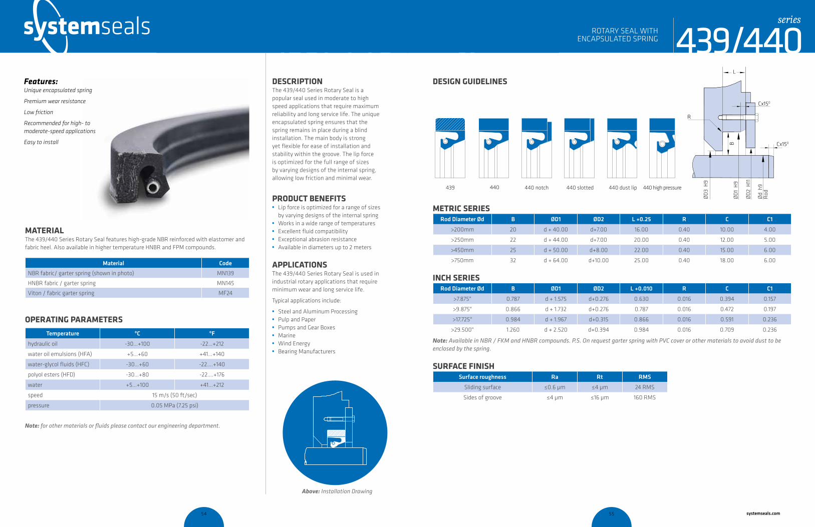
systemseals.com | 9505 Midwest Avenue, Cleveland, OH 44125 | 440.735.0200
Description The 439/440 Series Rotary Seal is a popular seal used in moderate to high speed applications that require maximum reliability and long service life. The unique encapsulated spring ensures that the spring remains in place during a blind installation. The main body is strong yet flexible for ease of installation and stability within the groove. The lip force is optimized for the full range of sizes by varying designs of the internal spring, allowing low friction and minimal wear.
proDuct Benefits • Lip force is optimized for a range of sizes
by varying designs of the internal spring• Works in a wide range of temperatures • Excellent fluid compatibility • Exceptional abrasion resistance• Available in diameters up to 2 meters
ApplicAtionsThe 439/440 Series Rotary Seal is used in industrial rotary applications that require minimum wear and long service life.
Typical applications include:
• Steel and Aluminum Processing• Pulp and Paper • Pumps and Gear Boxes• Marine • Wind Energy• Bearing Manufacturers
MAteriAl The 439/440 Series Rotary Seal features high-grade NBR reinforced with elastomer and fabric heel. Also available in higher temperature HNBR and FPM compounds.
Material Code
NBR fabric/ garter spring (shown in photo) MN139
HNBR fabric / garter spring MN145
Viton / fabric garter spring MF24
operAting pArAMeters
Temperature ºC ºF
hydraulic oil -30…+100 -22…+212
water oil emulsions (HFA) +5…+60 +41…+140
water-glycol fluids (HFC) -30…+60 -22….+140
polyol esters (HFD) -30…+80 -22….+176
water +5…+100 +41…+212
speed 15 m/s (50 ft/sec)
pressure 0.05 MPa (7.25 psi)
Note: for other materials or fluids please contact our engineering department.
Above: Installation Drawing
Features: Unique encapsulated spring
Premium wear resistance
Low friction
Recommended for high- to moderate-speed applications
Easy to install
ROTARy SEAL WiTH ENCAPSuLATED SPRiNG
cross-section of seal installation drawing icon
439/440series
systemseals.com | 9505 Midwest Avenue, Cleveland, OH 44125 | 440.735.0200
Metric seriesRod Diameter Ød B ØD1 ØD2 L +0.25 R C C1
>200mm 20 d + 40.00 d+7.00 16.00 0.40 10.00 4.00
>250mm 22 d + 44.00 d+7.00 20.00 0.40 12.00 5.00
>450mm 25 d + 50.00 d+8.00 22.00 0.40 15.00 6.00
>750mm 32 d + 64.00 d+10.00 25.00 0.40 18.00 6.00
inch seriesRod Diameter Ød B ØD1 ØD2 L +0.010 R C C1
>7.875" 0.787 d + 1.575 d+0.276 0.630 0.016 0.394 0.157
>9.875" 0.866 d + 1.732 d+0.276 0.787 0.016 0.472 0.197
>17.725" 0.984 d + 1.967 d+0.315 0.866 0.016 0.591 0.236
>29.500" 1.260 d + 2.520 d+0.394 0.984 0.016 0.709 0.236
Note: Available in NBR / FKM and HNBR compounds. P.S. On request garter spring with PVC cover or other materials to avoid dust to be enclosed by the spring.
surfAce finishSurface roughness Ra Rt RMS
Sliding surface ≤0.6 µm ≤4 µm 24 RMS
Sides of groove ≤4 µm ≤16 µm 160 RMS
Design guiDelinesL
R
B
ØD
3 H
9
ØD
1 H
9
ØD
2 H
11
Ød
h9
Rod
Cx150
Cx150
440 notch 440 slotted440 440 dust lip 440 high pressure439
ROTARy SEAL WiTH ENCAPSuLATED SPRiNG 439/440
series
54 55 systemseals.com

systemseals.com | 9505 Midwest Avenue, Cleveland, OH 44125 | 440.735.0200
DESCRIPTION The 442 Series High Speed Rotary Seal is a premium seal that offers a significant advantage over traditional rubber-and-textile rotary seals through its highly flexible, dual-construction internal metal spring and seal lip. The high flexibility of the seal lip and spring combination allows for use in applications with large deflections or very high speeds. The seal body has an internal reinforcing metal ring that ensures high retention during installation.
PRODUCT BENEFITS • Optimal seal life through consistent lip
force through the range of available sizes• One-piece molding lip design• High-retention, press-fit installation design • Works in a wide range of temperatures • Excellent fluid compatibility • Exceptional abrasion resistance• Available in diameters up to 2 meters
APPLICATIONSThe 442 Series Rotary Seal is used in industrial rotary applications with large deflections or very high speeds.
Typical applications include:
• Steel and Aluminum Processing• Pulp and Paper • Pumps and Gear Boxes• Electrical Generation • Wind Energy• Bearing Manufacturers
MATERIAL The 442 Series Rotary Seal is commonly available in both high-grade NBR compound and a high-temperature FPM compound. For extremely low temperatures, the seal can be supplied in silicone. The internal springs are constructed from 316 stainless steel.
Material Code
Nitrile rubber NBR + steel (shown in photo) MN40
Fluoroelastomer FPM + steel MF30
OPERATING PARAMETERS
NBR/metal MN40
Temperature ºC ºF
NBR -20…+120 -4…+248
FPM +20…+220 +4…+428
Silicone -60…+180 -76….+428
Max Speed (FPM) 35 m/s (115 ft/sec)
Max. Misalignment 2.5mm
Shaft Hardness >50 HRC
Note: for other materials or fluids please contact our engineering department.
Above: Installation Drawing
Features: Highly flexible seal lip
Robust construction with internal metal reinforcing ring
Dual spring construction
Premium wear resistance
Low friction
Recommended for high-speed, high-deflection applications
Easy to install
cross-section of seal installation drawing icon
442seriesHIGH-SPEED ROTARY SEAL
systemseals.com | 9505 Midwest Avenue, Cleveland, OH 44125 | 440.735.0200
SURFACE FINISHSurface roughness Ra Rt RMS
Sliding surface ≤0.6 µm ≤4 µm 24 RMS
Sides of groove ≤4 µm ≤16 µm 160 RMS
DESIGN GUIDELINESL
R
C1x30o
Cx30o
Ød
h8
ØD
tol
.
442seriesHIGH-SPEED ROTARY SEAL
INCH SERIESB L ØD tol. R C C1
0.500 0.625 d + 1.000 0.016 0.060
0.750 0.687 d +1.500 0.016 0.080
0.750 0.750 d +1.500 0.016 0.080
1.000 0.812 d + 2.000 0.016 0.118
1.000 0.875 d + 2.000 0.016 0.118
1.250 1.000 d + 2.500 0.016 0.125
groove ØD Tolerances
up to 3.000 ±0.001
>3.000 & <6.000 ±0.0015
>6.000 & <10.000 ±0.002
>10.000 & <20.000 +0.002/-0.004
>20.000 & <40.000 +0.002/-0.006
>40.000 +0.002/-0.010
C (lead-in chamfer)
up to 10.000 0.275
>10.000 0.500
METRIC SERIESB L ØD tol. R C C1
15.00 15.00 d + 30 0.40 1.50
20.00 20.00 d + 40 0.40 2.00
25.00 19.00 d + 50 0.40 3.00
25.00 22.23 d + 50 0.40 3.00
groove ØD Tolerances
up to 76 ±0.025
77-150 ±0.040
151-255 ±0.050
256-510 +0.05/-0.10
511-1015 +0.05/-0.15
>1015 +0.05/-0.25
C (lead-in chamfer)
up to 250 7.00
>250 12.00
see
tabl
e
see
tabl
ese
e ta
ble
see
tabl
e56 57 systemseals.com
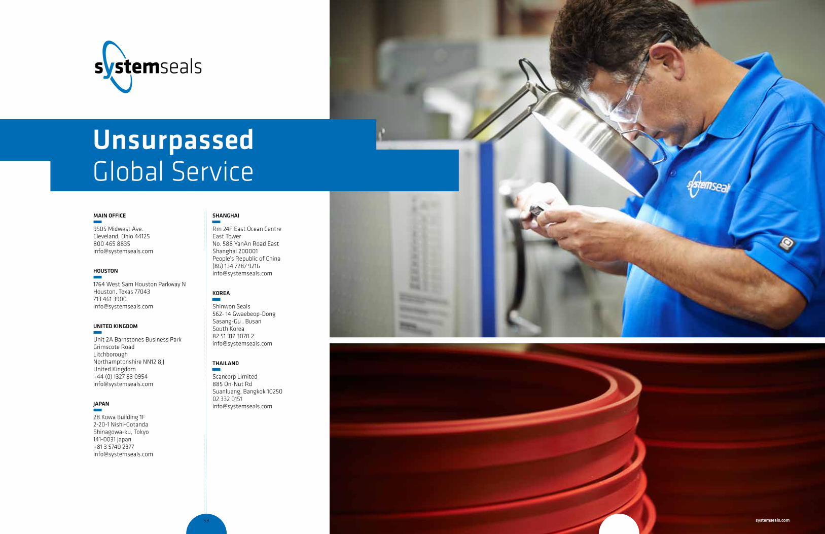
mAin OFFiCe
9505 Midwest Ave.Cleveland, Ohio 44125800 465 [email protected]
HOustOn
1764 West Sam Houston Parkway NHouston, Texas 77043713 461 [email protected]
uniteD kinGDOm
Unit 2A Barnstones Business ParkGrimscote RoadLitchboroughNorthamptonshire NN12 8JJUnited Kingdom+44 (0) 1327 83 [email protected]
JAPAn
28 Kowa Building 1F2-20-1 Nishi-GotandaShinagowa-ku, Tokyo141-0031 Japan+81 3 5740 [email protected]
sHAnGHAi
Rm 24F East Ocean CentreEast TowerNo. 588 YanAn Road EastShanghai 200001People’s Republic of China(86) 134 7287 [email protected]
kOReA
Shinwon Seals562- 14 Gwaebeop-Dong Sasang-Gu , Busan South Korea 82 51 317 3070 [email protected]
tHAilAnD
Scancorp Limited885 On-Nut RdSuanluang, Bangkok 1025002 332 [email protected]
unsurpassed Global Service
58 59 systemseals.com

You’re only as Strong as Your Weakest leak.
For emergency response call:
USA 216 220 1800
systemseals.com