Embed Size (px)
Citation preview
SpyglassUser Guide
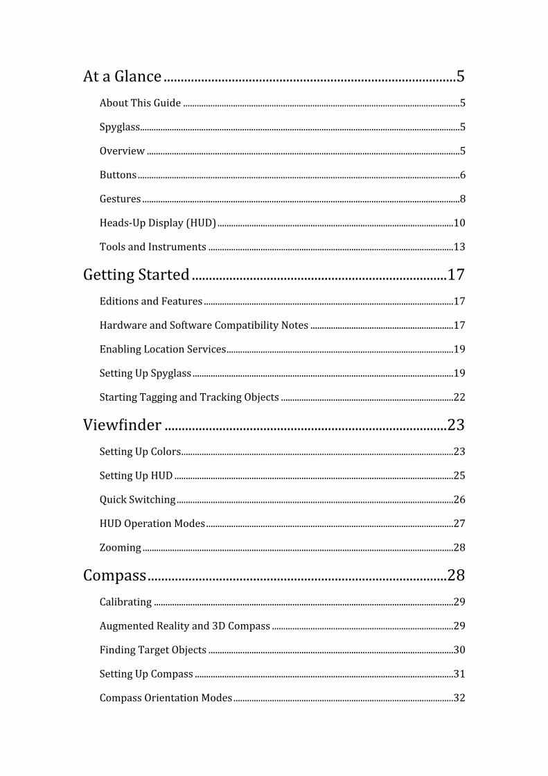
......................................................................................At a Glance 5..........................................................................................................................About This Guide 5
.............................................................................................................................................Spyglass 5
..........................................................................................................................................Overview 5
..............................................................................................................................................Buttons 6
............................................................................................................................................Gestures 8
........................................................................................................Heads-‐Up Display (HUD) 10
............................................................................................................Tools and Instruments 13
...........................................................................Getting Started 17..............................................................................................................Editions and Features 17
...............................................................Hardware and Software Compatibility Notes 17
....................................................................................................Enabling Location Services 19
...................................................................................................................Setting Up Spyglass 19
............................................................................Starting Tagging and Tracking Objects 22
...................................................................................ViewVinder 23........................................................................................................................Setting Up Colors 23
...........................................................................................................................Setting Up HUD 25
..........................................................................................................................Quick Switching 26
.............................................................................................................HUD Operation Modes 27
.........................................................................................................................................Zooming 28
........................................................................................Compass 28....................................................................................................................................Calibrating 29
................................................................................Augmented Reality and 3D Compass 29
............................................................................................................Finding Target Objects 30
..................................................................................................................Setting Up Compass 31
.................................................................................................Compass Orientation Modes 32
..............................................................................Gyrocompass 34.................................................................................................Starting Using Gyrocompass 34
..............................................................................................Determining Starting Bearing 35
............................................................................................................Drifts and Adjustments 36
..................................................................................................GPS 37.............................................................................................................................Setting Up GPS 37
...............................................................................................................Getting GPS Readings 38
..........................................................................................................................Setting Up Units 38
.............................................................................................Finder 39........................................................................................................................................Overview 39
...........................................................................................................................................Buttons 40
...............................................................................................................Quick Target Tagging 41
............................................................................................................................Adding Targets 43
......................................................................................................................Managing Targets 45
...............................................................................................................Finding and Tracking 46
................................................................................Observing Location Targets on Maps 47
..........................................................................................Tracker 48..................................................................................................................Setting Up Tracking 49
.........................................................................................................................................Tracking 50
..............................................................................Finding Target Objects with Compass 51
................................................................................................Stars 51...........................................................................................................................Setting Up Stars 51
...............................................................................................................Finding and Tracking 52
...................................................................Navigating by Sun, Moon, Polaris and Stars 52
...............................................................................................Maps 53
..........................................................................................................................Setting Up Maps 53
..............................................................................................................Panning and Scrolling 54
.........................................................................................................................................Zooming 54
.................................................................................RangeVinder 54...........................................................Measuring Distances with Optical RangeVinder 55
...........................................................................................Sextant 55...............................................................................Measuring Angle Deltas with Sextant 55
....................................................................Angular Calculator 56................................................................................................................Setting Up Calculator 56
.................................................................................................Calculating Object Distances 57
.............................................................................................Calculating Object Dimensions 57
....................................................................................Getting Angle Deltas From Sextant 57
..................................................................................Getting Object Distances with Maps 58
................................................................................Inclinometer 59
...........................................................................................Camera 59
..........................................................Precision and Accuracy 60
...............................................................................................Hints 60.....................................................................Measuring Distances Between Map Points 60
........................................................................Troubleshooting 60
...............................................................................................F.A.Q. 61
At a Glance
About This Guide
This guide describes the features of:• Spyglass 3.3• Commander Compass 3.3• Commander Compass Lite 3.3
All the software navigation products above belong to the Spyglass series.
Within the scope of this guide all the products will be referred to as Spyglass.
PDF & ePUB
This manual in PDF and ePUB formats is available for download at our site — visit http://happymagenta.com to get the manual and sync it to your device.
Spyglass
With the Spyglass 3D augmented reality navigation and advanced mil spec compass you may tag, Vind and track in real-‐time multiple locations, bearings, Sun, Moon, stars and use it as a hi-‐tech viewVinder, a gyrocompass, an optical rangeVinder, a visual sextant, maps, GPS, angular calculator, inclinometer and zoom camera.
Spyglass serves as a useful tool to solve a range of tasks arising during all types of outdoor activities from tagging visited places like a car, a camp or a hotel for later Vinding as well as during hunting, Vishing, hiking, scouting, seafaring, sports and touring.
Spyglass is designed with a passion to real milspec devices and is based on an idea to create a tool similar to viewVinders commonly seen in sci-‐Vi, military and action movies.
Overview
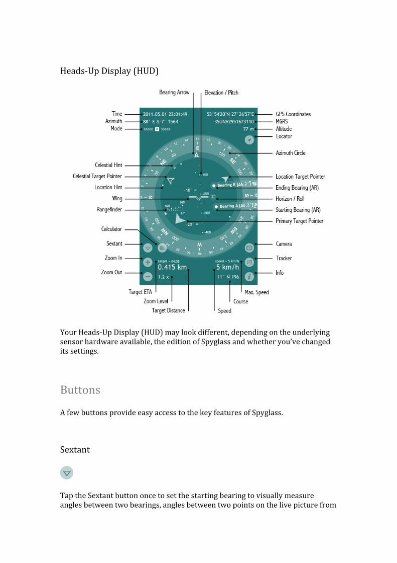
Heads-‐Up Display (HUD)
Your Heads-‐Up Display (HUD) may look different, depending on the underlying sensor hardware available, the edition of Spyglass and whether you’ve changed its settings.
Buttons
A few buttons provide easy access to the key features of Spyglass.
Sextant
Tap the Sextant button once to set the starting bearing to visually measure angles between two bearings, angles between two points on the live picture from
the camera or angles between two device attitudes. Tap the Sextant button second time to set the ending bearing and to complete the measurement. When both the starting and the ending bearings are set the Calculator button is revealed and the augmented reality markers of both the starting and the ending bearings are updated with the measured delta angle. Tap the Sextant button for the third time to clear the selected bearings and to hide the Calculator button.
Calculator
The Calculator button opens the Angular Calculator tool passing there the angle measured by the Sextant tool. The Angular Calculator tool allows calculating distances, angles and sizes of objects when only two of these parameters are known.
Zoom In and Zoom Out
Tapping the Zoom In or the Zoom Out button magniVies or miniVies either the live picture from the camera or the maps which one is active. The corresponding zoom level is also applied to the augmented reality object mapping and the measurement scales of the HUD.
Locator
Tap the Locator button to switch from either the current location or the maps current coordinate set manually by hand to the actual current location and the coordinate of the maps as per the current GPS sensor readings. The Locator button appears after you pan the maps or set the location by hand.
Camera
Tap the Camera button whether you need to take a picture with the HUD overlay or just to make a screenshot. The alternative way of making screenshots is to use the combination of the device Home button and the device Power button pressed in the same time.
Tracker
The Tracker button opens the Destinations menu that provides the access to the advanced target management and allows the quick addition or tagging of the current location, the current bearing or a location from the maps as a target for tracking. Targets added via the Destinations menu are automatically made primary.
Info
Tap the Info button to access the app settings and the accelerometer calibration.
Gestures
A few gestures available anywhere within the HUD screen make it easy to turn app features on or off, adjust the azimuth, switch between compass modes and cycle through the number of available HUD colors and Vilters.
Double Tap
The Double Tap gesture opens the Quick Switching menu. The Quick Switching menu allows quick and easy switching the camera, the maps or the compass modes on or off.
Long Tap
The Long Tap gesture opens the Current Attitude menu that provides copying options. Under the Current Attitude menu you may copy the current bearing, the current location coordinates or the current location link.
Pinch Zoom
The Pinch Zoom gesture provides the quick and easy way to magnify or minify the live picture from the camera along with the augmented reality object mappings and all dependent HUD scales and reticles.
Vertical Swipe
The Vertical Swipe gesture cycles back and forth through the color Vilters or lens that overlay either the live picture from the camera, the maps or the default screen background. The Vilters are useful when there is a need to get a better contrast between the HUD and what lies beneath or just in case you like to set up a color scheme of your choice.
Horizontal Swipe
The Horizontal Swipe gesture cycles through the available colors of the HUD elements. The HUD colors are indispensable when you need to create a color scheme you like or in case of a need of a better HUD contrast.
Diagonal Swipe
The Diagonal Swipe gesture cycles over the possible HUD background types. The HUD background is transparent and drawn right under the HUD elements and over the color Vilters layers.
Two-‐Finger Horizontal Swipe
The Two-‐Finger Horizontal Swipe gesture is used to adjust or correct the value of the current azimuth when operating in the gyrocompass or the manual orientation modes. It works the same way the aviation gyrocompass behaves.
Heads-‐Up Display (HUD)
The Heads-‐Up Display (HUD) is a transparent display that presents data over other images or views. Usually HUD data is either projected onto a transparent combiner that reVlects the monochromatic light waves or drawn over the live image on a screen. Sometimes the HUD is also referred to as On-‐Screen Display (OSD).
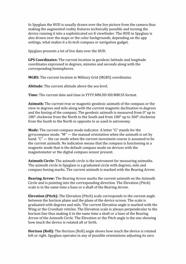
In Spyglass the HUD is usually drawn over the live picture from the camera thus making the augmented reality features technically possible and turning the device running it into a sophisticated sci-‐Vi viewVinder. The HUD in Spyglass is also drawn over the maps or the color backgrounds, depending on the app settings, what makes it a hi-‐tech compass or navigation gadget.
Spyglass presents a lot of live data over the HUD.
GPS Coordinates: The current location in geodesic latitude and longitude coordinates expressed in degrees, minutes and seconds along with the corresponding hemispheres.
MGRS: The current location in Military Grid (MGRS) coordinates.
Altitude: The current altitude above the sea level.
Time: The current date and time in YYYY.MM.DD HH:MM:SS format.
Azimuth: The current true or magnetic geodesic azimuth of the compass or the view in degrees and mils along with the current magnetic declination in degrees and the boxing of the compass. The geodesic azimuth is measured from 0° up to 180° clockwise from the North to the South and from 180° up to 360° clockwise from the South to the North in opposite to as used in astronomy.
Mode: The current compass mode indicator. A letter “G” stands for the gyrocompass mode. “M” — the manual orientation when the azimuth is set by hand. “C” — the car mode when the current movement course is assumed to be the current azimuth. No indication means that the compass is functioning in a magnetic mode that is the default compass mode on devices with the magnetometer or the digital compass sensor present.
Azimuth Circle: The azimuth circle is the instrument for measuring azimuths. The azimuth circle in Spyglass is a graduated circle with degrees, mils and compass boxing marks. The current azimuth is marked with the Bearing Arrow.
Bearing Arrow: The Bearing Arrow marks the current azimuth on the Azimuth Circle and is pointing into the corresponding direction. The Elevation (Pitch) scale is in the same time a base or a shaft of the Bearing Arrow.
Elevation (Pitch): The Elevation (Pitch) scale corresponds to the current angle between the horizon plane and the plane of the device screen. The scale is graduated with degrees and mils. The current Elevation angle is marked with the Wing or the Crosshair reticles. The Elevation scale is always perpendicular to the horizon line thus making it in the same time a shaft or a base of the Bearing Arrow of the Azimuth Circle. The Elevation or the Pitch angle is the one showing how much the device is rotated aft or forth.
Horizon (Roll): The Horizon (Roll) angle shows how much the device is rotated left or right. Spyglass operates in any of possible orientations adjusting its zero
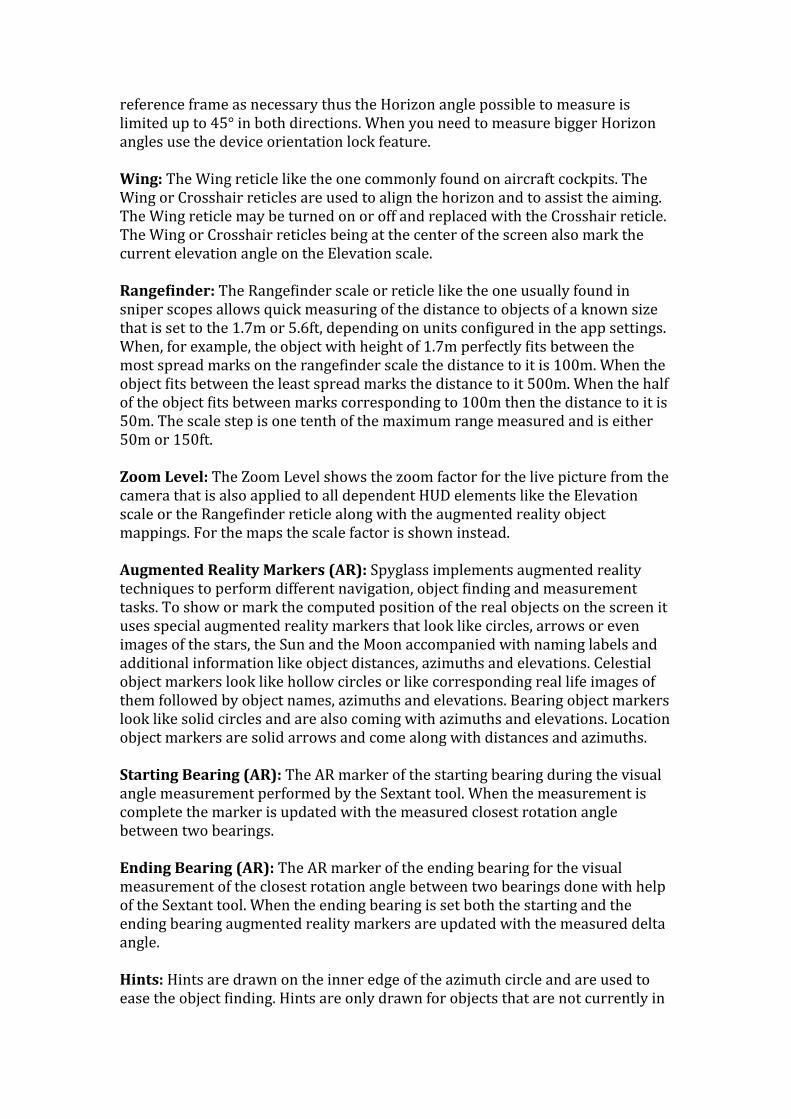
reference frame as necessary thus the Horizon angle possible to measure is limited up to 45° in both directions. When you need to measure bigger Horizon angles use the device orientation lock feature.
Wing: The Wing reticle like the one commonly found on aircraft cockpits. The Wing or Crosshair reticles are used to align the horizon and to assist the aiming. The Wing reticle may be turned on or off and replaced with the Crosshair reticle. The Wing or Crosshair reticles being at the center of the screen also mark the current elevation angle on the Elevation scale.
RangeCinder: The RangeVinder scale or reticle like the one usually found in sniper scopes allows quick measuring of the distance to objects of a known size that is set to the 1.7m or 5.6ft, depending on units conVigured in the app settings. When, for example, the object with height of 1.7m perfectly Vits between the most spread marks on the rangeVinder scale the distance to it is 100m. When the object Vits between the least spread marks the distance to it 500m. When the half of the object Vits between marks corresponding to 100m then the distance to it is 50m. The scale step is one tenth of the maximum range measured and is either 50m or 150ft.
Zoom Level: The Zoom Level shows the zoom factor for the live picture from the camera that is also applied to all dependent HUD elements like the Elevation scale or the RangeVinder reticle along with the augmented reality object mappings. For the maps the scale factor is shown instead.
Augmented Reality Markers (AR): Spyglass implements augmented reality techniques to perform different navigation, object Vinding and measurement tasks. To show or mark the computed position of the real objects on the screen it uses special augmented reality markers that look like circles, arrows or even images of the stars, the Sun and the Moon accompanied with naming labels and additional information like object distances, azimuths and elevations. Celestial object markers look like hollow circles or like corresponding real life images of them followed by object names, azimuths and elevations. Bearing object markers look like solid circles and are also coming with azimuths and elevations. Location object markers are solid arrows and come along with distances and azimuths.
Starting Bearing (AR): The AR marker of the starting bearing during the visual angle measurement performed by the Sextant tool. When the measurement is complete the marker is updated with the measured closest rotation angle between two bearings.
Ending Bearing (AR): The AR marker of the ending bearing for the visual measurement of the closest rotation angle between two bearings done with help of the Sextant tool. When the ending bearing is set both the starting and the ending bearing augmented reality markers are updated with the measured delta angle.
Hints: Hints are drawn on the inner edge of the azimuth circle and are used to ease the object Vinding. Hints are only drawn for objects that are not currently in
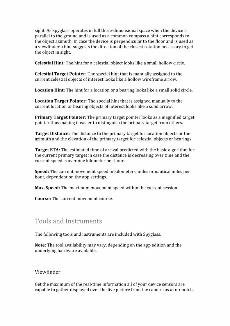
sight. As Spyglass operates in full three-‐dimensional space when the device is parallel to the ground and is used as a common compass a hint corresponds to the object azimuth. In case the device is perpendicular to the Vloor and is used as a viewVinder a hint suggests the direction of the closest rotation necessary to get the object in sight.
Celestial Hint: The hint for a celestial object looks like a small hollow circle.
Celestial Target Pointer: The special hint that is manually assigned to the current celestial objects of interest looks like a hollow wireframe arrow.
Location Hint: The hint for a location or a bearing looks like a small solid circle.
Location Target Pointer: The special hint that is assigned manually to the current location or bearing objects of interest looks like a solid arrow.
Primary Target Pointer: The primary target pointer looks as a magniVied target pointer thus making it easier to distinguish the primary target from others.
Target Distance: The distance to the primary target for location objects or the azimuth and the elevation of the primary target for celestial objects or bearings.
Target ETA: The estimated time of arrival predicted with the basic algorithm for the current primary target in case the distance is decreasing over time and the current speed is over one kilometer per hour.
Speed: The current movement speed in kilometers, miles or nautical miles per hour, dependent on the app settings.
Max. Speed: The maximum movement speed within the current session.
Course: The current movement course.
Tools and Instruments
The following tools and instruments are included with Spyglass.
Note: The tool availability may vary, depending on the app edition and the underlying hardware available.
ViewVinder
Get the maximum of the real-‐time information all of your device sensors are capable to gather displayed over the live picture from the camera as a top-‐notch,
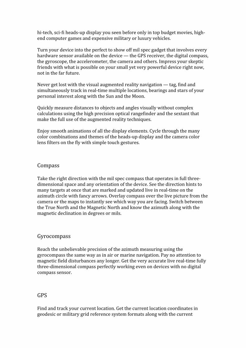
hi-‐tech, sci-‐Vi heads-‐up display you seen before only in top budget movies, high-‐end computer games and expensive military or luxury vehicles.
Turn your device into the perfect to show off mil spec gadget that involves every hardware sensor available on the device — the GPS receiver, the digital compass, the gyroscope, the accelerometer, the camera and others. Impress your skeptic friends with what is possible on your small yet very powerful device right now, not in the far future.
Never get lost with the visual augmented reality navigation — tag, Vind and simultaneously track in real-‐time multiple locations, bearings and stars of your personal interest along with the Sun and the Moon.
Quickly measure distances to objects and angles visually without complex calculations using the high precision optical rangeVinder and the sextant that make the full use of the augmented reality techniques.
Enjoy smooth animations of all the display elements. Cycle through the many color combinations and themes of the heads-‐up display and the camera color lens Vilters on the Vly with simple touch gestures.
Compass
Take the right direction with the mil spec compass that operates in full three-‐dimensional space and any orientation of the device. See the direction hints to many targets at once that are marked and updated live in real-‐time on the azimuth circle with fancy arrows. Overlay compass over the live picture from the camera or the maps to instantly see which way you are facing. Switch between the True North and the Magnetic North and know the azimuth along with the magnetic declination in degrees or mils.
Gyrocompass
Reach the unbelievable precision of the azimuth measuring using the gyrocompass the same way as in air or marine navigation. Pay no attention to magnetic Vield disturbances any longer. Get the very accurate live real-‐time fully three-‐dimensional compass perfectly working even on devices with no digital compass sensor.
GPS
Find and track your current location. Get the current location coordinates in geodesic or military grid reference system formats along with the current
altitude above the sea level, the current and the maximum speed and the movement course. Use imperial, metric or nautical units. Copy location as coordinates or as a maps link to share.
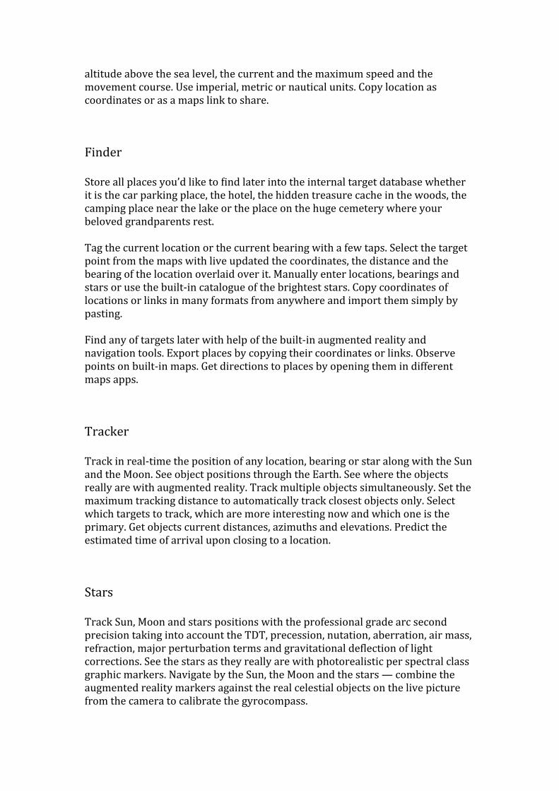
Finder
Store all places you’d like to Vind later into the internal target database whether it is the car parking place, the hotel, the hidden treasure cache in the woods, the camping place near the lake or the place on the huge cemetery where your beloved grandparents rest.
Tag the current location or the current bearing with a few taps. Select the target point from the maps with live updated the coordinates, the distance and the bearing of the location overlaid over it. Manually enter locations, bearings and stars or use the built-‐in catalogue of the brightest stars. Copy coordinates of locations or links in many formats from anywhere and import them simply by pasting.
Find any of targets later with help of the built-‐in augmented reality and navigation tools. Export places by copying their coordinates or links. Observe points on built-‐in maps. Get directions to places by opening them in different maps apps.
Tracker
Track in real-‐time the position of any location, bearing or star along with the Sun and the Moon. See object positions through the Earth. See where the objects really are with augmented reality. Track multiple objects simultaneously. Set the maximum tracking distance to automatically track closest objects only. Select which targets to track, which are more interesting now and which one is the primary. Get objects current distances, azimuths and elevations. Predict the estimated time of arrival upon closing to a location.
Stars
Track Sun, Moon and stars positions with the professional grade arc second precision taking into account the TDT, precession, nutation, aberration, air mass, refraction, major perturbation terms and gravitational deVlection of light corrections. See the stars as they really are with photorealistic per spectral class graphic markers. Navigate by the Sun, the Moon and the stars — combine the augmented reality markers against the real celestial objects on the live picture from the camera to calibrate the gyrocompass.
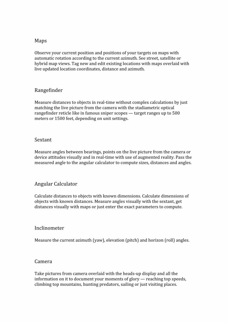
Maps
Observe your current position and positions of your targets on maps with automatic rotation according to the current azimuth. See street, satellite or hybrid map views. Tag new and edit existing locations with maps overlaid with live updated location coordinates, distance and azimuth.
RangeVinder
Measure distances to objects in real-‐time without complex calculations by just matching the live picture from the camera with the stadiametric optical rangeVinder reticle like in famous sniper scopes — target ranges up to 500 meters or 1500 feet, depending on unit settings.
Sextant
Measure angles between bearings, points on the live picture from the camera or device attitudes visually and in real-‐time with use of augmented reality. Pass the measured angle to the angular calculator to compute sizes, distances and angles.
Angular Calculator
Calculate distances to objects with known dimensions. Calculate dimensions of objects with known distances. Measure angles visually with the sextant, get distances visually with maps or just enter the exact parameters to compute.
Inclinometer
Measure the current azimuth (yaw), elevation (pitch) and horizon (roll) angles.
Camera
Take pictures from camera overlaid with the heads-‐up display and all the information on it to document your moments of glory — reaching top speeds, climbing top mountains, hunting predators, sailing or just visiting places.
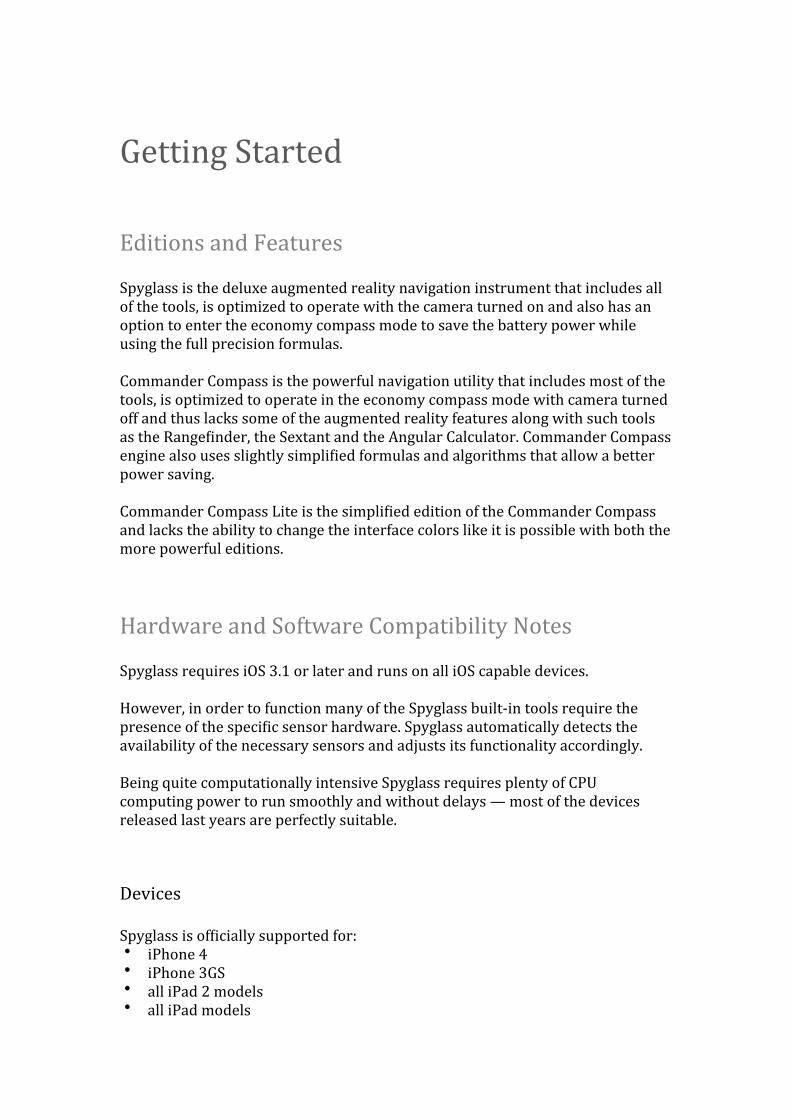
Getting Started
Editions and Features
Spyglass is the deluxe augmented reality navigation instrument that includes all of the tools, is optimized to operate with the camera turned on and also has an option to enter the economy compass mode to save the battery power while using the full precision formulas.
Commander Compass is the powerful navigation utility that includes most of the tools, is optimized to operate in the economy compass mode with camera turned off and thus lacks some of the augmented reality features along with such tools as the RangeVinder, the Sextant and the Angular Calculator. Commander Compass engine also uses slightly simpliVied formulas and algorithms that allow a better power saving.
Commander Compass Lite is the simpliVied edition of the Commander Compass and lacks the ability to change the interface colors like it is possible with both the more powerful editions.
Hardware and Software Compatibility Notes
Spyglass requires iOS 3.1 or later and runs on all iOS capable devices.
However, in order to function many of the Spyglass built-‐in tools require the presence of the speciVic sensor hardware. Spyglass automatically detects the availability of the necessary sensors and adjusts its functionality accordingly.
Being quite computationally intensive Spyglass requires plenty of CPU computing power to run smoothly and without delays — most of the devices released last years are perfectly suitable.
Devices
Spyglass is ofVicially supported for:• iPhone 4• iPhone 3GS• all iPad 2 models• all iPad models
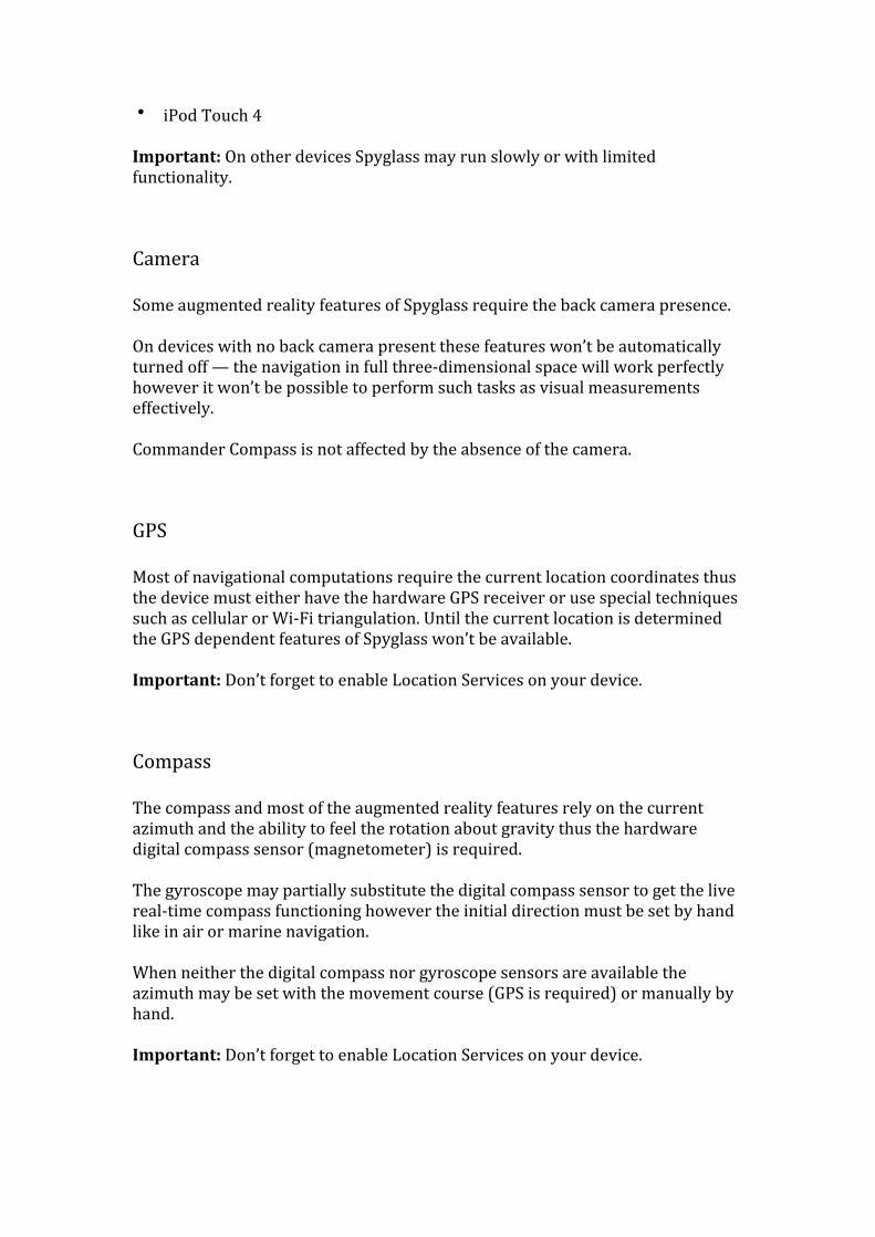
• iPod Touch 4
Important: On other devices Spyglass may run slowly or with limited functionality.
Camera
Some augmented reality features of Spyglass require the back camera presence.
On devices with no back camera present these features won’t be automatically turned off — the navigation in full three-‐dimensional space will work perfectly however it won’t be possible to perform such tasks as visual measurements effectively.
Commander Compass is not affected by the absence of the camera.
GPS
Most of navigational computations require the current location coordinates thus the device must either have the hardware GPS receiver or use special techniques such as cellular or Wi-‐Fi triangulation. Until the current location is determined the GPS dependent features of Spyglass won’t be available.
Important: Don’t forget to enable Location Services on your device.
Compass
The compass and most of the augmented reality features rely on the current azimuth and the ability to feel the rotation about gravity thus the hardware digital compass sensor (magnetometer) is required.
The gyroscope may partially substitute the digital compass sensor to get the live real-‐time compass functioning however the initial direction must be set by hand like in air or marine navigation.
When neither the digital compass nor gyroscope sensors are available the azimuth may be set with the movement course (GPS is required) or manually by hand.
Important: Don’t forget to enable Location Services on your device.
Gyroscope
The hardware gyroscope sensor is only required for the gyrocompass mode.
Enabling Location Services
In order to be able to read the data from the device built-‐in hardware sensors Spyglass must be allowed to use the Location Services that must be enabled on the device. On the Virst Spyglass launch it will ask the permission to use the Location Services. Otherwise, the permission should be granted explicitly — within the device settings choose Location Services and turn them on.
Setting Up Spyglass
Most of the Spyglass features are conVigured automatically and are ready to use out of the box. However to operate properly there may be a need to calibrate hardware sensors, to tune a few parameters such as measurement units and to conVigure the most pleasing color theme.
Calibrating the Accelerometer
To feel the device motion Spyglass uses both the gravity sensor (accelerometer) and in case it is available the rotation sensor (gyroscope). The data from both the sensors is slightly different on each device and depends on many factors even such exotic as the temperature. Thus, the gravity vector as the device feels it may deviate a bit from the real gravity. On the other hand, the horizon level of the building or another object that needs to be used as the measurement base may also be imperfect. In such cases the gravity needs calibration.
Spyglass uses per orientation calibration proViles that allow a better precision for the full range three-‐dimensional space for all of the six orientations of the device possible.
To calibrate tap the Info button and choose Calibration, align the device with help of the guides drawn on the device screen and tap the screen anywhere to conVirm the new gravity reference.
Calibrating the accelerometer is not an equivalent to setting a zero reference. The calibration takes into account the gravity vector adjustments only — the rotation about gravity is ignored to avoid the incorrect azimuth measuring.
To calibrate the accelerometer as per the current device orientation the device should be positioned into an ideal position referring to the orientation of the device so the device axis would match the real gravity and the horizon plane.
Compass and Gyro
The compass in Spyglass may use different visual styles, different angular units, the True North or the Magnetic North and also may operate in different modes.
Spyglass automatically detects the best compass operation mode available on the device. The default is the magnetic mode when the heading data is read from the digital compass sensor.
In case the gyroscope is also available it will be used automatically to assist the digital compass sensor in order to reach the better accuracy and to reduce the inVluence of surrounding magnetic Vield disturbances.
As any magnetic compass the device digital compass sensor is very sensitive to the surrounding magnetic Vields that may produce signiVicant inVluence on its readings.
Upon detection of signiVicant disturbances in surrounding magnetic Vields a message reporting magnetic interference pops up with calibration instructions. Following instructions and moving the device in a Vigure eight motion recalibrates the compass.
The digital compass sensor is calibrated automatically and gains its precision as you move and rotate the device. Thus moving and rotating the device improves the accuracy even in case no any interference being reported.
In the gyrocompass mode the compass entirely relies on gyroscope readings and reads the data from the digital compass sensor only once to set the initial azimuth.
The gyrocompass mode is recommended for all devices even having the digital compass sensor. However, the gyrocompass mode needs to be explicitly turned on because the improper initial azimuth may cause confusion.
On devices with no digital compass sensor the initial azimuth always needs to be set by hand — you may even launch Spyglass facing the North to get the gyrocompass instantly set up with the proper azimuth.
In the car mode the movement course read from the GPS receiver is used as the current azimuth thus making it useful when the device is mounted onto a moving vehicle like a car, a bike or a yacht.
To set up the compass and the gyroscope tap the Info button, choose Settings, scroll to Compass and Compass mode sections and turn the compass parameters on or off.
Units
Spyglass supports metric, imperial, nautical and military units. Unit settings detected automatically based on the device regional settings. However, the regional settings of the device may not match your preference. To set up the units Spyglass will use tap the Info button, choose Settings, scroll to Units section and turn the unit parameters on or off.
Augmented Reality Navigation
To avoid confusion the augmented reality three-‐dimensional navigation formulas for locations by default don’t take into account location altitudes and elevations due to the Earth curvature and compute elevations in a simpliVied way for very close objects only.
Elevation angles of locations that are far away on the opposite side of the Earth or on roofs of nearby skyscrapers in such cases tend to zero in a way like the locations would belong to the horizon plane.
If location altitudes and elevations due to the Earth curvature will be taken into account by the navigation formulas elevation angles of locations will closely match their real positions.
Locations that are on the opposite side of the Earth will appear as objects under your feet and locations that are on roofs of nearby skyscrapers will appear as objects high above your head.
Hints and target pointer arrows suggesting directions towards objects mark correct azimuths on the azimuth circle only when the device is in the face up orientation and is parallel to the ground. Otherwise, the object hints suggest the directions of the closest rotations necessary to get the objects in sight as in space and aircraft computer simulation games.
The closer the object within the horizon plane, the deeper below or the higher above the object — the bigger the deviation between the object azimuth and the angle that the object pointer marks on the compass azimuth circle.
The ignorance of location altitudes and elevations due to the Earth curvature can be turned off or back on — tap the Info button, scroll to Augmented Reality section and turn the ignorance parameters as per current needs.
Colors and Filters
The Spyglass color theme consists of the three base colors — the color of the lens or the overlay that also stands for the primary background color when the camera is turned off, the color of the HUD elements and the color of the HUD elements background.
Changing colors helps to get a better contrast between the HUD elements and the live picture from the camera lying beneath. As the live picture may change frequently color switching is easily done with a few simple gestures.
A single Vinger swiping or sliding in vertical, horizontal and diagonal directions over the HUD screen cycles through the available colors allowing setting up the most contrast of the most pleasing color theme, including the terminator and the night vision alike.
Starting Tagging and Tracking Objects
With Spyglass you may Vind and simultaneously track in real-‐time multiple locations, bearings and stars along with the Sun and the Moon in full three-‐dimensional space with both the augmented reality techniques and the advanced compass.
You may tag your current location or the bearing you are facing and start tracking them instantly — tap the Tracker button and choose Add Current Location or Add Current Bearing.
In case you need the higher precision when tagging your location — tap the Tracker button and choose Add Map Location to select the exact position with the maps (an Internet connection is required). The live updated coordinates, distance and azimuth of the location drawn over the maps make the selection easier.
Spyglass instantly starts tracking new targets. Direction hints and pointing arrows suggesting either the object azimuth or the direction of the closest rotation necessary to get the object in sight drawn on the inner edge of the compass azimuth circle.
The distance or the other primary target information appears at the bottom left corner of the HUD. When you are closing to the primary target the estimated time of arrival is predicted and the sound notiVies as you approach the target.
Position the device into the face up orientation to use Spyglass as the advanced compass and see the object hints or the pointing arrows to show the object azimuths — the directions to the objects.
Rotate the device following the object direction hints or the pointing arrows to get the objects in sight and read their tracking information seeing the object augmented reality markers corresponding to the real object positions drawn over the live picture from the camera.
You may add more new and edit or delete existing targets of different types, choose a primary target and select secondary targets — tap the Tracker button and choose Manage Destinations.
Copy location coordinates or links from anywhere in many supported formats, including Geocaching, and import them simply with pasting — Spyglass parses the pasteboard content automatically and asks you to import the coordinates found. You also may paste the copied coordinates manually at any time.
ViewVinderThe viewVinder shows you everything related to your location, the direction you are facing and all the device sensor readings in a form of a hi-‐tech heads-‐up display overlaid over the live picture from the camera.
You may change the amount of data shown, the precision and the amount of marks on the measurement scales along with the measurement units used. You can also turn on or off and conVigure individual HUD elements. The quick switching makes it easy to switch operation modes on the Vly.
The color lens Vilter, the HUD color and the color of the HUD background are switched on the Vly with simple gestures to choose the most suitable and the most favorable color theme. You may also adjust the opacity of the color lens layer.
Setting Up Colors
The HUD overlays a constantly changing picture and that is quite hard to foresee which color combination Vits best to achieve the Vinest contrast to distinguish between the HUD and the picture. To overcome that and to allow creating favorable color themes a few simple gestures allow fast and easy way of cycling back and forth through the available colors on the Vly. You may change the color of the lens of the overlay that also stands for the primary background color when the camera is turned off, the color of the HUD elements and the color of the HUD elements background.
Lens Filter Colors
The lens color Vilter or the coloring layer is drawn right behind the HUD over the default black background or the live picture from the camera. That allows to set the color of the HUD screen while running in compass mode with the camera turned off or to colorize the live picture coming from the camera producing the night vision, the interlaced spy alike and other effects.
Switch the lens Cilter color: Slide vertically with one Vinger over the HUD. Sliding from the bottom to the top or backwards cycles back and forth through the available colors of the lens Vilter.
Lens Filter Opacity
Tuning the lens Vilter opacity helps during the use of the viewVinder, the compass and the maps when there arises a need to improve the visibility of the HUD or what lies beneath. In the compass mode tuning the lens Vilter opacity allows choosing between the tones of the current lens Vilter color down to the completely black.
Tune the lens color opacity: Tap the Info button, choose Settings, scroll to Display section and use the Filter opacity slider to adjust the current opacity of the lens color Vilter.
HUD Elements Colors
The HUD elements color is the base of the HUD color theme. You may choose from the available colors to make the elements better visible or to match the desired color theme.
Switch the HUD elements color: Slide horizontally with one Vinger over the HUD, Sliding from the left to the right or backwards cycles back and forth through the available colors of the HUD elements.
HUD Elements Transparent Background Colors
The transparent background drawn under the compass azimuth circle, the augmented reality markers and a few other elements of the HUD makes them easier to see and allows additional customization of the look and feel and the color theme.
Switch the HUD elements transparent background color: Slide diagonally with one Vinger over the HUD. Sliding from the top left to the bottom right and backwards as well as sliding from the top right to the bottom left and backwards cycles back and forth through the available colors of the transparent background of the HUD elements.
Noteworthy Visual Styles
You may learn through the possibilities opening with the color theme customization features reading following tips on how to set up a few of interesting and notable color themes below.
Night Vision: Turn the camera on and set the HUD elements color to white, the HUD elements transparent background color to white, the lens Vilter color to green and the lens Vilter opacity to the maximum.
T-‐800: Turn the camera on and set the HUD elements color to white, the HUD elements transparent background color to white, the lens Vilter color to red and the lens Vilter opacity to the maximum.
BMW: Turn the camera off and set the HUD elements color to red, the HUD elements transparent background color to black, the lens Vilter color to red and the lens Vilter opacity to the one Vifth.
Tactical Maps: Turn the maps on and set the HUD elements color to white, the HUD elements transparent background color to black, the lens Vilter color to red or green and the lens Vilter opacity to the half.
Spy Intelligence Maps: Turn the maps on and set the HUD elements color to white, the HUD elements transparent background color to black, the lens Vilter color to red or green with the interlacing effect and the lens Vilter opacity to the half. The colors with the interlacing effect follow the solid colors in the palette.
Setting Up HUD
To Vit needs of your current task best and to customize the look and feel of the HUD you may turn on or off and conVigure individual HUD elements or tune the app settings affecting the way it displays the data.
Wing and Crosshair
The wing or the miniature wings are representing the actual wings on an attitude indicator aircraft instrument, also known as gyro horizon or artiVicial horizon, used to inform the pilot of the orientation of the aircraft relative to the Earth. The wing marks the current elevation or pitch angle and also shows the current horizon or roll angle of the attitude of the device.
The crosshair reticle helps aiming and also serves the same purpose as the wing reticle. The wing reticle helps aiming also though in some cases may be more appropriate.
You may choose either the crosshair or the wing reticle as well as turn both the reticles off. To set up the aiming reticle tap the Info button, choose Settings, scroll to Display section and turn the reticles on or off.
RangeVinder
The stadiametric or holdover reticle helps measuring distances to objects with known dimensions without complex calculations. Tap the Info button, choose Settings, scroll to Display section and turn the rangeVinder reticle on or off.
Scales and Units
The scale precision and unit parameters affect all the features through.
Turning on the precise scales affects the amount of marks graduated on the compass azimuth circle and the elevation angular scale to make measuring easier. You may like the cleaner look with simpliVied scales or vice versa.
Turning on military units shows extra information where applicable, including extra marks for angular mils on the compass azimuth circle and extra location coordinates in military grid format.
You can also switch between metric, imperial or nautical measurement units. The nautical units when turned on override the metric or the imperial unit settings for distances and speeds.
To set up the scale precision and the units Spyglass will use tap the Info button, choose Settings, scroll to Units section and turn the necessary parameters on or off.
Quick Switching
The Spyglass built-‐in instruments operate in a variety of different modes using different hardware sensors and interface elements. Spyglass provides the easy way of toggling modes — the quick mode switching.
You may use the quick mode switching to adjust the interface, the usage of the hardware sensors and to switch between different operation modes as per your current needs.
Double tap anywhere within the HUD screen with a single Vinger to open the Quick Switching menu and choose one of the available modes — the current state of each mode is appended after a colon.
Toggle the camera: Double tap anywhere within the HUD screen with a single Vinger to open the Quick Switching menu and choose Camera to turn the camera on or off.
Toggle the maps: Double tap anywhere within the HUD screen with a single Vinger to open the Quick Switching menu and choose Maps to turn the maps on or off.
Switch between compass operation modes: Double tap anywhere within the HUD screen with a single Vinger to open the Quick Switching menu and choose Gyrocompass, Car Mode or Manual Orientation to activate the gyrocompass, the car or the manual compass operation mode. To return to the default digital compass orientation mode that uses the magnetometer or the digital compass sensor only turn off any other active mode.
HUD Operation Modes
The HUD along with the compass may be overlaid over the live picture from the camera, over the color background or over the maps what deVines the three modes of operation for the HUD — the camera or the viewVinder mode, the compass mode and the maps mode.
The HUD operation modes correlate with the compass operation modes of the same name however they are not the same. The HUD modes are deVined by the way Spyglass is used in a whole. The compass modes depend on the way the compass suggests directions to target objects.
You may switch between the operation modes of the HUD using either the quick mode switching or the app settings. To switch the HUD operation modes tap the Info button, choose Settings, scroll to Display or Map sections.
ViewVinder
The viewVinder or the camera mode is the default mode of the HUD operation — the HUD is overlaid over the live picture from the camera and you may fully use the augmented reality features.
Compass
The compass mode is the battery power saving mode of the HUD operation — the HUD is overlaid over the color background and the camera is turned off to reduce the hardware processing power usage. The augmented reality features aren’t turned off along with the camera in the compass mode however it won’t be possible to perform such tasks as visual measurements effectively.
Maps
The maps mode is exactly same as the compass mode of the HUD operation and the only difference is that the HUD is overlaid over the maps. However the maps may also be used with the camera turned on in the same time — you may then enter the maps mode on the Vly by holding the device level Vlat to the ground.
Zooming
Zooming in and out with both the Zoom In and the Zoom Out buttons or with the Pinch Zoom gesture magniVies and miniVies either the live picture from the camera or the maps. While in the viewVinder mode with the camera turned on the zoom level is also applied to the augmented reality object mapping and all dependent HUD scales and reticles.
CompassThe three-‐dimensional compass shows which direction you are facing and directions to all targets being tracked. You may use it as a common two-‐dimensional compass by positioning the device parallel to the ground or take the full advantage of the three-‐dimensional augmented reality navigation by using the compass in the viewVinder mode otherwise.
You can choose the Magnetic North or the True North, see the magnetic declination and use both the common azimuth degrees and the military angular
mils units. The compass can be overlaid over the live picture from the camera, the maps or just a simple color background.
The tracker and the Vinder tools use the compass to aid Vinding and navigating to a number of chosen targets — multiple direction hints are marked and updated live on the azimuth circle of the compass in the same time.
Calibrating
The compass calibrates automatically as you move and rotate the device. Waving the device in a Vigure eight recalibrates the compass and improves the accuracy even in case no interference being reported.
Augmented Reality and 3D Compass
The compass in Spyglass is similar to a traditional magnetic compass and is different in the same time. The traditional compass is designed to navigate in two dimensions (2D). The compass in Spyglass operates in three dimensions (3D) and also works as the object Vinding instrument that shows directions to many targets at once.
The bearing arrow of the compass with the elevation angular scale that forms the body or the shaft of the arrow shows the current direction you are facing. In the same time the bearing arrow tip marks the current direction on the azimuth circle of the compass.
The compass usage differs depending on the orientation of the device.
When the device is in the face up orientation and is leveled Vlat to the ground the bearing arrow of the compass shows the direction the device top is facing — the compass operates in the 2D or the common compass mode.
When the device is positioned in different orientation and the inclination of the device screen plane to the horizon plane is over eleven degrees the bearing arrow of the compass shows the direction the device camera is facing — the compass operates in the 3D or the viewVinder mode also referred to as the augmented reality mode.
The transition between the compass and the viewVinder or the 2D and the 3D modes of the compass is seamless — soon you’ll get used to both the modes. To see the direction you are facing just watch the bearing arrow of the compass. The azimuth of the direction you are currently facing appears at the top left corner of the HUD screen.
The bearing arrow of the compass always shows the correct current azimuth regardless the device orientation however that is different when it comes to object direction hints, pointers and pointing arrows.
Object direction hints, pointers and pointing arrows are basically the same elements yet are different shapes drawn on the inner edge of the azimuth circle of the compass.
The compass always operates in three dimensions though when the device is held parallel to the Vloor due to the geometric rules getting directions or just navigating to objects with hints gets the properties of operating within two dimensions.
When the compass is used in the 2D or the compass mode the direction hint to an object being tracked shows the direction to the object and marks the object azimuth on the azimuth circle of the compass.
When the compass is used in the 3D or the viewVinder mode the direction hint to an object being tracked shows the direction of the closest rotation necessary to get the object in sight. The same is true for the 2D mode. However in 3D mode object direction hints are not directly related to the azimuth circle of the compass.
Finding Target Objects
Finding target objects is easy with the compass whether the target is a location, a bearing or a star. The compass shows directions hints of various shapes on the inner edge of the azimuth circle of the compass.
To see the direction to the object of your choice level the device Vlat to the horizon plane to enter the compass mode and rotate the device so the bearing arrow of the compass matches the direction hint of the object.
Then rotate the device either aft or forth in the direction the hint suggests to see the position of the object with the augmented reality in the viewVinder mode — when the target moves in sight the augmented reality marker shows the position of the object. The current distance along with the current azimuth and the current elevation of the object is provided nearby the object augmented reality marker, depending on the type of the object.
You may also rotate the device just once straight in the direction of the closest rotation necessary to get the object in sight instead of performing the two rotations according the azimuth and the elevation of the target — the direction hint always shows the direction of the closest rotation regardless of the usage mode of the compass.
The way of Vinding objects with two rotations may be a bit easier until you will get used to the single rotation way — the target information shows the current azimuth and the current elevation of the object when the current primary target is set to either a bearing or a star. The second rotation is not necessary in case you only need to get the current azimuth of the target.
Setting Up Compass
While the transition between the usage modes of the compass is automatic and seamless you may also need to set up a few other compass parameters affecting the look and the behavior of the compass as per your taste or the current task.
Tune the compass: Tap the Info button, choose Settings, scroll to Compass or Compass mode sections and turn the compass parameters on or off.
Classic vs. Backwards
The compass may appear as the classic or as the backwards compass.
The classic or the common compass appearance is designed in a way to be looked at the compass from the top, as it would be on a Vloor — the bearing arrow of the compass points from the observer and is drawn at the opposite side of the azimuth circle of the compass. The classic appearance of the compass is a perfect Vit for navigation tasks and to be used with the maps.
The backwards compass appearance is designed to look at the compass from aside, as it would be on a wall or a window — the North and the South are inverted and the bearing arrow of the compass is drawn at the bottom of the compass azimuth circle.
The backwards appearance of the compass is often used within viewVinders though only a part of the azimuth circle or the azimuth scale of the compass is shown at a given moment of time.
When the backwards appearance of the compass is in use the direction hints of the objects being tracked show the correct direction however because of the inverted azimuth circle of the compass the hints are not related to the compass azimuth scale.
True vs. Magnetic
The compass can show the azimuth of the direction you are facing referring to either the Magnetic North or the True North along with the magnetic declination for your current location.
The True North is a constant and refers to the geographic North Pole. The Magnetic North shifts over time and refers to the pole of the magnetic Vield of the Earth. The magnetic declination is the angle between directions to the Magnetic North and the True North.
Switching to the Magnetic North only affects the compass and the current azimuth shown at the top of the HUD — the other instruments rely on, use and show the azimuth referring to the True North. The azimuth for tracked objects always refers to the True North although in the 2D mode of the compass direction hints mark object azimuths on the azimuth circle of the compass referring to the Magnetic North.
Magnetic vs. Gyroscope vs. Gyrocompass
The compass uses the rotation sensor or the gyroscope in different ways. The compass relies on the digital compass sensor or the magnetometer and may use the rotation sensor to improve the accuracy.
On the devices with the built-‐in rotation hardware sensor with the gyroscope turned on the compass behaves as the gyroscope assisted compass improving the accuracy of the digital compass sensor.
In the gyrocompass mode when the compass completely relies on the gyroscope the digital compass sensor is only used once to set the set the starting bearing. The gyroscope also makes the live compass technically possible on the devices with no built-‐in digital compass sensor.
The magnetometer is very sensitive to the magnetic or other environmental interference affecting the accuracy of the compass. Even with the gyroscope assistance the accuracy of the compass may experience the signiVicant inVluence of the surrounding magnetic Vields — you need to calibrate the compass the Virst time you use it and occasionally after that.
The accuracy of the compass operating in the gyrocompass mode is not affected by the magnetic interference though you may need to set the starting bearing and to adjust the current bearing occasionally as the gyroscope may experience slight drifts due to the impact of a lot of different outer forces produced even by your heartbeat.
Compass Orientation Modes
The compass relies on the current azimuth and the ability to feel the rotation about gravity provided by the built-‐in hardware digital compass sensor and the built-‐in hardware rotation sensor.
To get the live compass showing the direction you are facing in real-‐time one of the sensors is required. The gyroscope allows feeling the rotation about gravity and is a way more precise though it feels no magnetic azimuth — you need to set the starting azimuth when the magnetometer is missing on the device.
The orientation modes of the compass depend on the presence of the built-‐in hardware sensors and the way they are used. With no sensors that are feeling the rotation about gravity available on the device the direction you are facing can be determined by either the movement course provided by the GPS sensor or manually by hand.
Magnetic
In the magnetic orientation mode of the compass the current azimuth of the compass is read out of the digital compass sensor or the magnetometer. The magnetic orientation mode is the default mode on the devices with the built-‐in digital compass sensor.
Gyroscope Assisted Compass
In the gyroscope or the gyroscope assisted mode of the compass orientation the current azimuth is read out of the digital compass however the gyrocompass sensor readings are used to improve the accuracy of the compass by reducing the inVluence of the surrounding magnetic interference. The gyroscope mode of the orientation of the compass is the default mode on the devices having both the magnetometer and the gyroscope sensors.
Gyrocompass
In the gyrocompass mode of the orientation of the compass the current azimuth is approximated with the complex formulae from the readings of the built-‐in hardware rotation sensor.
On the devices with the digital compass sensor the magnetometer readings are only used once to set the initial azimuth of the compass — on the devices with no digital compass sensor the starting bearing of the compass must be set manually by hand — you may also use the augmented reality to calibrate or to set the initial azimuth with the Sun, the Moon and the stars by matching the augmented
reality markers with the real celestial objects on the live picture from the camera.
The gyrocompass orientation mode of the compass is recommended mode for the devices having all the built-‐in necessary hardware sensors though the mode should be turned on by hand.
Car
In the car mode of the compass orientation the azimuth is approximated by the current course of the movement determined from the readings of the built-‐in GPS receiver. In order to get the current azimuth in the car orientation mode of the compass the presence of the hardware GPS sensor is required and you may need to move fast enough. The car mode of compass orientation is the default mode on the devices with neither the digital compass nor the gyroscope but having the GPS hardware available.
Manual
In the manual compass orientation mode the azimuth is only set manually by hand and neither of the hardware sensors is in use. The manual mode of the compass orientation is the default mode on the devices with neither of the required sensors. Despite the manual compass orientation mode provides no live real-‐time azimuth updates you still may use it to see directions by matching the augmented reality markers of the Sun, the Moon or the stars with the real images of the celestial objects on the live picture from the camera.
GyrocompassThe gyrocompass allows to overcome the digital compass sensor interference with environmental magnetic Vields and to signiVicantly gain the accuracy of the compass by relying on the gyroscope sensor only. The initial azimuth is set automatically when the digital compass sensor is available. You may set and adjust the azimuth later manually.
Starting Using Gyrocompass
To switch to the gyrocompass mode of the compass orientation double tap anywhere on the HUD and then choose Gyrocompass or tap the Info button,
choose Settings, scroll to Compass mode section and turn the gyrocompass mode on or off.
Upon entering the gyrocompass mode of the orientation of the compass the initial azimuth is set automatically on the devices with the built-‐in digital compass sensor.
On the other devices with no the magnetometer hardware sensor present the starting bearing is always set to zero degrees or to the North — launch Spyglass facing the North to instantly get the gyrocompass azimuth set up properly or slide across the HUD horizontally with two Vingers otherwise to set the proper azimuth.
Determining Starting Bearing
The compass in the gyrocompass orientation mode can be used as usual providing the live azimuth updates in real-‐time however in case the device has no built-‐in hardware digital compass sensor the starting bearing must be set manually by hand. On the other hand the gyrocompass may be calibrated with the Sun, the Moon and the stars or by using a few other more or less precise techniques.
The accuracy of the azimuth approximation with the methods described below signiVicantly depends on the readings from the built-‐in hardware GPS sensor — you may even like to set your location manually or with the maps. The maps require an Internet connection however the GPS sensor is not required if the current location is set manually.
For less accurate direction approximation you may also use one of the traditional ways the scouts would use like exploring the bark of the trees to know the direction to the South.
Sun, Moon, Stars
To set the proper starting bearing of the gyrocompass by the Sun, the Moon or the stars choose the celestial body clearly visible in the sky. You may need to add the chosen celestial body to the Vinder to get the object direction hint mark appearing on the inner edge of the azimuth circle of the compass — the Sun, the Moon and Polaris need no tagging.
To adjust the azimuth with the celestial body clearly visible on the live picture from the camera point the lens of the camera into the object direction the way to get the object in sight and slide over the HUD horizontally with two Vingers until the augmented reality marker for the chosen celestial body matches its position on the live image.
To adjust the azimuth with the celestial body barely or not visible on the live picture from the camera like a small star at night position the device into the face up orientation Vlat to the ground, point with the device top in the direction to the object and slide over the HUD horizontally with two Vingers until the hint corresponding to the chosen celestial body matches the direction you are facing shown with the bearing arrow of the compass.
Maps
To use maps to set the starting bearing of the gyrocompass look around and choose a noticeable object like a building or a road, tap the Tracker button, choose Add Map Location to open the maps, scroll or pan the maps until the object is positioned by the screen center — the azimuth of the selected point updates at the upper left corner of the screen as you scroll and pan the maps.
You may remember the azimuth, cancel the addition of the new object and use the direction to the known object to adjust the gyrocompass starting bearing accordingly — level the device Vlat to the horizon plane, point with the device top in the direction to the chosen object and adjust the azimuth with the two Vinger sliding until the current compass azimuth matches the remembered one.
You may also complete the object addition to the Vinder and then use the hint or the augmented reality marker of the object to adjust the gyrocompass the way the azimuth adjusted using the celestial bodies.
Course
To set the starting bearing of the gyrocompass with the course of the movement start moving straight in some direction fast enough until the course information appears at the lower right corner of the screen, position the device Vlat to the ground into the face up orientation, point with the device top into the direction you moved and adjust the azimuth with the two Vinger sliding until the current azimuth of the compass matches the course.
Drifts and Adjustments
The gyroscope or the built-‐in hardware rotation sensor of the device has the unbelievable precision making the gyrocompass extremely accurate however the gyroscope experiences small drifts over time caused by lots of the external forces even such exotic as the beat of you own heart.
GPSThe GPS shows the geographical coordinates of your location along with the altitude above the sea level. As you move the GPS also reports your movement speed and the current course. You may choose the geodesic and the military grid coordinate formats along with the imperial, metric, nautical and military measurement units.
Setting Up GPS
Every of the augmented reality and the navigation features depend on your current location read out of the build-‐in hardware GPS receiver sensor and the accuracy of the readings.
On the devices with no built-‐in hardware GPS receiver sensor the coordinates of the current location are triangulated involving cellular base stations and Wi-‐Fi access points in the closest surroundings though the accuracy of the positioning is signiVicantly lower.
The accuracy of the positioning can be improved with the certiVied external GPS accessories like Bad Elf GPS on both types of the devices having and having not the built-‐in hardware GPS sensors. For best accuracy you may even like to set the current location manually by hand.
The navigation and augmented reality formulae need the exact coordinates of current location to compute the directions to and the positions of the objects. The closer the object and the lower the accuracy of the GPS readings the higher the relative offset of the approximated position of the target object.
Even the compass that operates referring to the True North needs exact location coordinates to compute the current magnetic declination speciVic for the current geographic area.
Setting You Current Location Manually
To improve the accuracy of the augmented reality and the navigation features you may manually set your current location to the exact coordinates by selecting a point on the maps or by pasting coordinates or links in many formats.
The maps are only available online — the manual coordinate entry dialog opens otherwise. The starting coordinates of the location the maps or the dialog open
with are taken in the following order out of the current readings of the built-‐in hardware GPS receiver, from the content of the pasteboard or from the current location coordinates.
To set the current location coordinates online with the maps tap the Info button, choose Location and select the coordinates by centering the maps at the chosen point. To set the current location coordinates ofVline with the manual coordinate entry dialog tap the Info button, select Location and enter the coordinates.
Once the current location coordinates are set by hand the live real-‐time updating of the GPS data stops and the Locator button appears at the upper right corner of the HUD.
Tapping the Locator button starts back the live real-‐time updating of the GPS data and switches back into the automatic mode of the detection of the current location coordinates.
Getting GPS Readings
The current location and movement data read from the built-‐in hardware GPS receiver sensor or approximated with the triangulation involving cellular base stations and Wi-‐Fi access points updates live at the HUD.
The coordinates of the current location in the geodesic and the military grid formats along with the current geographic altitude above the sea level appear at the upper right corner of the screen.
The maximum and the current speed along with the current movement course appear at the lower right corner of the HUD screen. The maximum speed is only tracked within the current session or the run of Spyglass.
Sharing Current Coordinates
You may share the current location information using email or copy the current location coordinates and the current location link into the pasteboard. To access the export options tap and hold anywhere over the HUD screen until the export menu appears.
Setting Up Units
You can switch between metric, imperial or nautical measurement units and use the military grid and the geodesic formats for coordinates. Turning on the MGRS
shows the extra coordinates of the current location in military grid format at the upper right corner of the HUD. Switching the nautical units on overrides the metric or the imperial units settings for distances and speeds. To set up units tap the Info button, choose Settings, scroll to Units section and turn the necessary parameters on or off.
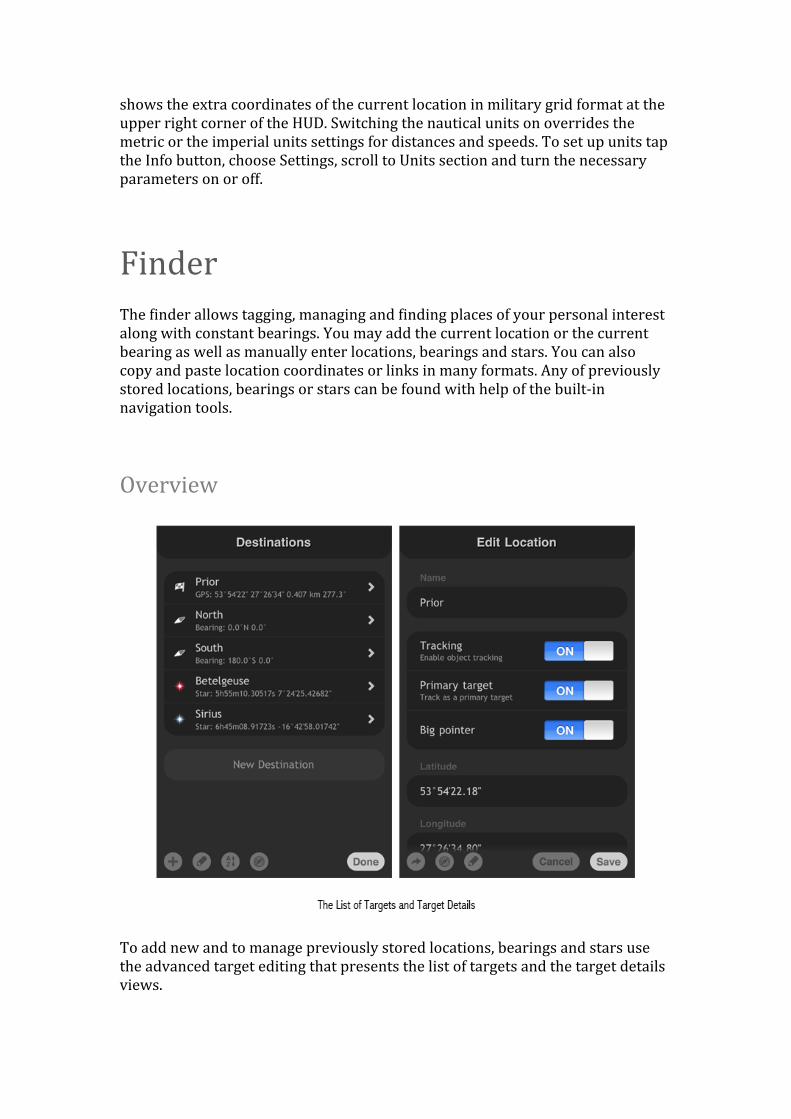
FinderThe Vinder allows tagging, managing and Vinding places of your personal interest along with constant bearings. You may add the current location or the current bearing as well as manually enter locations, bearings and stars. You can also copy and paste location coordinates or links in many formats. Any of previously stored locations, bearings or stars can be found with help of the built-‐in navigation tools.
Overview
To add new and to manage previously stored locations, bearings and stars use the advanced target editing that presents the list of targets and the target details views.
The target details view may look different, depending on the type of the target.
To open the target list tap the Tracker button and select Manage Destinations, to view or to edit the target details, or to access the options for the speciVic target type choose the desired object from the target list.
Buttons
New Destination
Tap the New Destination button to add a new location, bearing or star.
Edit
Tap the Edit button to access the list or the object editing options.
Sort
Tap the Sort button to sort the target list.
Compass
Tap the Compass button to observe the locations on the maps.
Export
Tap the Export button for export options.
Quick Target Tagging
The quick target tagging allows adding the current location using the current coordinates, adding a map location using the coordinates of a point from the maps, adding the current bearing using the current azimuth and the current elevation and adding a location at a distance in the direction you are currently facing — you may add targets with only a few taps from within the HUD without a need to enter coordinates or any other parameters by hand.
Tagging the current location is the fast and easy way of storing your current location for later Vinding though due to the accuracy of the GPS you may like to add the location with the maps instead.
The maps open centered at the current location coordinates — this way you may check the accuracy of the GPS readings instantly and visually reVine the coordinates of the location as necessary however you may use the maps only online.
You may tag the current location ofVline without the maps — later you can use the maps to reVine the stored location coordinates to the exact position wanted although the accuracy of the GPS readings is quite high outdoors.
The current bearing is tagged with the respect to both the current azimuth and the current elevation however only the current azimuth is taken into account when tagging a location at a distance in the current direction.
Targets may also be tagged with the pasting feature. You may copy the location coordinates and location links in many formats from mail, web and anywhere — when you launch Spyglass it analyzes the content of the pasteboard and asks you to import the coordinates when found.
The pasting feature supports really lots of coordinate formats — coordinates in military grid format and coordinates consisting of the latitude followed by the longitude in degrees, minutes and seconds or decimal degrees or degrees that come along with decimal minutes or seconds of arc — when both the latitude and the longitude are followed or prepended with the Earth hemisphere letters the order of coordinates may be any.
You may also paste locations as maps links in Google, Yandex and Bing formats.
After quick tagging of a target the big pointing arrow appears — the target added with the quick target tagging becomes the primary target and the tracking starts
instantly. There can be only one primary target thus the previous primary target becomes common — you may set or change the type of any target later.
Adding Current Location
To tag the current location using the coordinates of the current location tap the Tracker button and choose Add Current Location — enter the name of the new target when asked.
Adding Map Location
To tag a location using the coordinates of a point from the maps tap the Tracker button, choose Add Map Location and select the coordinates by centering the maps at the chosen point — enter the name of the new target when asked.
Adding Current Bearing
To tag the current bearing using the current azimuth and the current elevation tap the Tracker button and choose Add Current Bearing — enter the name of the new target when asked.
Adding with Distance
To tag a location at a distance in the direction you are currently facing rotate the device until the bearing arrow of the compass marks the desired azimuth, on the compass azimuth circle, tap the Tracker button, choose Add With Distance and enter the distance in kilometers, miles or knots, depending on units conVigured in the app settings — enter the name of the new target when asked.
Pasting
To paste coordinates or maps links copy the coordinates of one location or copy one maps link in one of the supported formats from mail, web or anywhere and launch Spyglass — the coordinate entry dialog opens asking you to import the coordinates when found.
The manual coordinate entry dialog shows you the copy of the content found in the pasteboard — there is no need to edit it whether it is a map link or location
coordinates — the dialog opens and the pasting becomes available only when the valid data is found in the pasteboard — you may just conVirm the location data and it will be automatically processed.
The quick tagging with pasting asks to import the new location only once per unique coordinates or a maps link — you may paste the copied location later within other places otherwise.
Adding Targets
Alternatively to the quick target tagging the advanced target editing allows to manually enter locations, bearings and stars and to use the maps, the built-‐in catalogue of the brightest stars and the pasting feature to add new targets. To enter the advanced target editing tap the Tracker button and select Manage Destinations.
Locations
To add a new location target tap the New Destination button, choose Location and enter the location data. Location targets are deVined with the name and the geographic coordinates — the latitude, the longitude and the altitude.
You may enter the latitude and the longitude using a lot of formats — type in from one up to three numbers for degrees, minutes and seconds of arc or hours, minutes and seconds of arc. The altitude uses either metric meter of imperial feet, depending on units conVigured in the app settings.
You may also enter the location coordinates using the MGRS WGS84 format.
Each of the numbers may be either integer or decimal using the dot character as a delimiter. The default format uses degrees, minutes and seconds — there is no need to append numbers with unit type characters though you may explicitly set the type of the unit of each number by appending it with one of the [d], [°], [’], ["] characters for degrees, minutes and seconds of a degree or with [h], [m], [s] for hours, minutes and seconds of an hour.
The characters of the Earth hemisphere [N], [S], [E], [W] can be either prepended or appended to the coordinate — there is no need to type the Earth hemispheres when the coordinate is prepended by the minus sign.
Map Locations
To add a new location target using the maps tap the New Destination button, choose Add Map Location and select the coordinates by centering the maps at the chosen point — the coordinates are passed to the new location form.
Bearings
To add a new bearing target tap the New Destination button, choose Bearing and enter the bearing data. Bearing targets are deVined with the name and the horizontal coordinates — the azimuth and the elevation.
You may enter the azimuth and the elevation using a lot of formats — type in from one up to three numbers for degrees, minutes and seconds of arc or hours, minutes and seconds of arc.
Each of the numbers may be either integer or decimal using the dot character as a delimiter. The default format uses degrees, minutes and seconds — there is no need to append numbers with unit type characters though you may explicitly set the type of the unit of each number by appending it with one of the [d], [°], [’], ["] characters for degrees, minutes and seconds of a degree or with [h], [m], [s] for hours, minutes and seconds of an hour.
Stars
To add a new star target tap the New Destination button, choose Star and enter the star data. Star target objects are deVined with the name and the equatorial coordinates — the right ascension, the declination and proper motions in both the right ascension and the declination.
You may enter the right ascension and the declination using a lot of formats — type in from one up to three numbers for degrees, minutes and seconds of arc or hours, minutes and seconds of arc. Proper motions use milliseconds of arc. The star equatorial coordinates referring to the J2000 epoch — you may use any of the star coordinates from the FK2000 catalogue.
Each of the numbers may be either integer or decimal using the dot character as a delimiter. The default format for the right ascension uses hours, minutes and seconds however for the declination the default format uses degrees, minutes and seconds — there is no need to append numbers with unit type characters though you may explicitly set the type of the unit of each number by appending it with one of the [d], [°], [’], ["] characters for degrees, minutes and seconds of a degree or with [h], [m], [s] for hours, minutes and seconds of an hour.
Adding Brightest Stars From Catalogue: Tap the New Destination button, choose Star From Catalogue and select the star you want to add.
Pasting
To add a new location target using the pasting feature tap the New Destination button and choose Paste — the coordinates and the name of the copied location are passed to the new location form.
The pasting feature supports really lots of coordinate formats — coordinates in military grid format and coordinates consisting of the latitude followed by the longitude in degrees, minutes and seconds or decimal degrees or degrees that come along with decimal minutes or seconds of arc — when both the latitude and the longitude are followed or prepended with the Earth hemisphere letters the order of coordinates may be any.
You may also paste locations as maps links in Google, Yandex and Bing formats.
Managing Targets
The advanced target editing allows editing previously stored locations, bearings and stars, allows using the maps to visually reVine the coordinates of locations and allows pasting the location coordinates or maps links. With the advanced target editing you may also rename, reorder, sort and delete any of previously stored targets. To switch to the advanced editing tap the Tracker button and select Manage Destinations — the list of the previously stored targets appears.
Editing
To view the details of, to open or to edit any of the previously stored targets choose the desired one from the target list — the object view or the object editing form which are equally the same opens where you may rename the target, Vine tune the target parameters, export the target details and perform other target related tasks.
Reselecting Location Coordinates with Maps
To set the location coordinates using the maps open the target details view, tap the Edit button, choose Select On Map and select the coordinates by centering the maps at the chosen point.
Pasting Location Coordinates
The set the location coordinates using the pasting feature open the target details view, tap the Edit button and choose Paste — the coordinates of the copied location are passed to the location form.
Reordering and Sorting
The order of targets as they appear in the list doesn’t affect anything. You may reorder the targets as per you taste or for your convenience. To reorder the list of the targets tap the Edit button and then drag the icon next to an object at the right to a new place in the list. To sort the list tap the Sort button and choose the sorting option — sorting may help looking up the closest and the most actual of targets allowing reordering the list by the target range and the target visibility.
Deleting One and All Targets
To delete a single target tap the Edit button, then tap the icon next to an object at the left and tap Delete. You may also quick delete targets with the left to right swiping gesture. To delete all targets at once tap the Edit button, choose Clear Destinations and then tap Clear.
Finding and Tracking
In order to Vind any of the previously stored target locations, bearing or stars with the built-‐in navigation instruments the tracking should be turned on for destinations and stars globally and individually for each of the targets — the tracking is turned on by default globally and for all new objects. Targets may be of different types — primary, interesting or secondary. The tracker tracks targets with the tracking turned on and displays the target direction hints along with the primary target information at the HUD.
Enabling Target Tracking
To switch the tracking for both the locations and the bearings globally tap the Info button, choose Settings, scroll to Navigation section and turn the tracking of the destinations on or off.
To switch the tracking for the stars globally tap the Info button, choose Settings, scroll to Stars section and turn the tracking of stars on or off — the tracking of the Sun and the Moon is turned on or off along with the global star tracking.
To toggle the tracking of the individual target objects tap the Tracker button, choose Manage Destinations, choose the target from the list of targets and turn the tracking on or off within the target details.
Choosing Primary Targets
To set the primary target tap the Tracker button, choose Manage Destinations, choose the target from the list of targets and turn the primary target switch on.
There can be only one primary target — the direction hint for the primary target appears at the inner edge of the compass azimuth circle as the biggest arrow and the target information appears at the lower left corner of the screen.
New targets added with the quick tagging become primary right away overriding previous primary targets — add targets with the editing interface otherwise to retain the current primary target.
Choosing Interesting or Secondary Targets
To set the target as one of the interesting targets tap the Tracker button, choose Manage Destinations, choose the target from the list of targets and turn the big pointer on within the target details.
There can be many interesting targets in the same time — the direction hints for the interesting targets appear at the inner edge of the compass azimuth circle as big arrows.
The other targets with the tracking turned on that are neither the primary nor the interesting are secondary — the direction hints for the secondary targets appear at the inner edge of the azimuth circle of the compass as little circles or as little arrows.
Observing Location Targets on Maps
You may observe all, tracked, in range and individual location targets on built-‐in maps as well as export points and get directions with supported external maps apps — Google Maps, Google Earth or Yandex Maps. You can also use the maps feature to overlay the compass over the maps.
Locations
To observe all, all in range, tracked or tracked in range location targets with the built-‐in maps tap the Tracker button, choose Manage Destinations, then tap the Compass button and choose accordingly.
The in range options are accessible with the tracking distance limit set only.
To observe an individual target with the built-‐in maps tap the Tracker button, choose Manage Destinations, choose the target from the list of targets, tap the Compass button within the target details and choose Show On Map.
Directions
To get the directions to the target with the Google Maps app tap the Tracker button, choose Manage Destinations, choose the target from the list of targets, tap the Compass button within the target details and choose Show Directions.
Opening with Different Maps Apps
To observe an individual target with one of the supported external maps apps tap the Tracker button, choose Manage Destinations, choose the target from the list of targets, tap the Compass button within the target details and choose one of the available — Google Maps, Google Earth or Yandex Maps. The supported maps apps need to be installed on the device — the option to use them won’t appear otherwise within the Show On Map menu accessible with the Compass button.
TrackerThe tracker allows real-‐time tracking of locations, bearings and stars. The tracker traces multiple objects simultaneously and calculates their positions, distances, azimuths and elevations, depending on your current location and the bearing you are facing. You may see where objects are with augmented reality even through the Earth and use the compass to get direction hints. You can choose several targets to track, the primary target and set tracking distance limits. As long as you are closing to the primary target the tracker plays audible notiVications, predicts the estimated time of arrival and keeps the track of the maximum speed.
Setting Up Tracking
With the tracker you may enable or disable the tracking of the target objects globally for locations, bearing or stars, set the maximum tracking range limit, use the navigation along the rhumb lines, use the big or the little direction hints and turn the audible notiVications on or off.
Enabling Location and Bearing Tracking
To switch the tracking for both the locations and the bearings globally tap the Info button, choose Settings, scroll to Navigation section and turn the tracking of the destinations on or off.
Enabling Star Tracking
To switch the tracking for the stars globally tap the Info button, choose Settings, scroll to Stars section and turn the tracking of stars on or off — the tracking of the Sun and the Moon is turned on or off along with the global star tracking.
Limiting Tracking Range
With the maximum tracking limit set the tracker tracks and updates directions to the in range location objects only — tap the Info button, choose Settings, scroll to Navigation and slide the Maximum tracking range slider to set the maximum distance or to turn the limit off.
Rhumb Line Navigation
The tracker allows navigation along both the shortest paths to the location objects or the rhumb lines. The azimuth to the target constantly changes while following the shortest path to the object while the course to the target object remains the same — following the rhumb line to the object requires continual changes in the track of the vehicle to maintain the constant course. Tap the Info button, choose Settings, scroll to Navigation section and turn the navigation along rhumb lines on or off.
Direction Hints, Pointers and Arrows
You may conVigure the tracker to show either the big direction hints to see the directions to the target objects with the big pointing arrows or the small hints to save the screen space.
The object direction hints appear at the inner edge of the azimuth circle of the compass — the little plus stands for the Polaris, the little x character shows the direction for the Sun, the smallest hollow circle shows the position of the Moon, small hollow circles suggest directions for the stars, small solid circles stand for both the locations and the bearings and the hollow or the solid pointing arrow tracks the direction to the primary target.
When the big pointers turned on globally the primary and the interesting targets use big either the hollow or the solid pointing arrows — the hollow arrows stand for the celestial target objects and the solid arrows track the location or the bearing targets — tap the Info button, select Settings, scroll to Navigation section and turn the big pointers on or off.
Beeping
The tracker may alert you with the audible notiVications as you are closing to the primary target — tap the Info button, select Settings, scroll to Navigation section and turn the beeping on or off.
Altitudes and The Earth Curvature
To avoid confusion with the directions to the targets the tracker by default does not take into account both the altitudes of the target locations and the curvature of the Earth.
Elevation angles of locations that are far away on the opposite side of the Earth or on roofs of nearby skyscrapers in such cases tend to zero in a way like the locations would belong to the horizon plane.
The ignorance of location altitudes and elevations due to the Earth curvature can be turned off or back on — tap the Info button, scroll to Augmented Reality section and turn the ignorance parameters as per current needs.
Tracking
The tracker simultaneously tracks multiple locations, bearings and stars — the purpose of the tracker is to compute the current positions of the target objects you choose yourself and to provide with the current object information — the current position, the current direction, the current distance to the object and more, depending on the type of the object.
The tracker computes distances, azimuths and elevations for the locations, shows directions for the constant bearings and computes azimuths along with elevations for the stars.
The primary target information appears at the lower left corner of the screen and the other target information appears besides the corresponding augmented reality markers. The estimated time of arrival is predicted and the audible alert plays as you close to the current location target. The maximum movement speed within the current session is also tracked as you move and appears at the lower left corner of the HUD.
Finding Target Objects with Compass
You may Vind any of the previously stored targets with the compass — the tracker shows and constantly updates in real-‐time the direction hints for the tracked objects and marks object positions at the live camera picture with both the compass and the augmented reality.
StarsThe tracker traces real-‐time positions of the Sun, the Moon and the stars with the professional grade arc second precision formulas taking into account the TDT, precession, nutation, aberration, air mass, refraction, major perturbation terms and gravitational deVlection of light corrections.
You may choose between the simple markers of star positions and photorealistic per spectral class graphic markers. You can enter star coordinates manually or use the built-‐in catalogue of the brightest stars.
You can also navigate by the Sun, the Moon and the stars by combining the augmented reality markers against the real celestial objects on the live picture from the camera to calibrate the gyrocompass.
Setting Up Stars
You may enable or disable the tracking of the celestial objects globally along with the tracking of the Polaris, the Moon and the Sun that are tracked as special objects together with the stars and choose the way the positions of the celestial objects marked with the augmented reality.
Enabling Star Tracking
To switch the tracking for the stars globally tap the Info button, choose Settings, scroll to Stars section and turn the tracking of stars on or off — the tracking of the Sun and the Moon is turned on or off along with the global star tracking.
Polaris
Polaris also called Northern Star, Pole Star or Lodestar is the brightest star in the constellation Ursa Minor — it is the current northern pole star very close to the northern celestial pole what makes it convenient for navigation purposes — tap the Info button, choose Settings, scroll to Stars section and turn the tracking of Polaris on or off. You may also add the Polaris by hand as a star from the built-‐in catalogue of the brightest stars.
Star Graphic Markers
The stars can use the either the simple hollow circles or the photorealistic per spectral class graphic images as the augmented reality markers showing the star positions — tap the Info button, choose Settings, scroll to Stars section and turn the graphic markers on or off
Finding and Tracking
You may Vind any of the previously added stars with the compass — the tracker shows and constantly updates in real-‐time the direction hints for the tracked stars and marks star positions at the live camera picture with both the compass and the augmented reality.
Navigating by Sun, Moon, Polaris and Stars
You may use the Sun, The Moon, Polaris and the stars to set the starting bearing of the gyrocompass — the most precise instrument for the azimuth measuring and for the navigation.
MapsThe maps show your current location along with locations of your targets. The built-‐in compass allows seeing the direction you are facing. The maps may use street, satellite or combined hybrid map views. You may choose points on maps for tracking or use maps to visually measure distances from the current location to remote objects.
Setting Up Maps
The maps allow choosing the map type from street, satellite or hybrid views, allow using the maps in different mode of the HUD operation and allow using the maps together with the HUD color themes.
ViewVinder vs. Compass
The maps may be used with both the viewVinder HUD operation mode with the camera turned on and with the compass HUD operation mode with the camera turned off. In the viewVinder mode with the camera turned on the maps appear only in the face up orientation of the device after you level the device Vlat to the ground — in the compass mode the maps are always visible.
To turn the maps on of off and to set other options of the maps tap the Info button, choose Settings, scroll to Maps sections and switch the parameters of the maps.
The maps can be turned on and off on the Vly with the quick switching menu — double tap anywhere at the HUD screen and choose Maps to toggle the maps on or off.
Switching Maps Views
To switch between the street, satellite or combined map views tap the Info button, choose Settings, scroll to Map Type section and choose the type of the maps view.
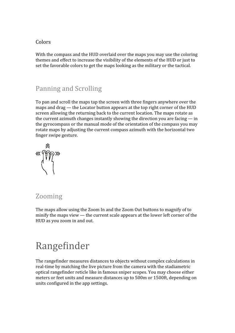
Colors
With the compass and the HUD overlaid over the maps you may use the coloring themes and effect to increase the visibility of the elements of the HUD or just to set the favorable colors to get the maps looking as the military or the tactical.
Panning and Scrolling
To pan and scroll the maps tap the screen with three Vingers anywhere over the maps and drag — the Locator button appears at the top right corner of the HUD screen allowing the returning back to the current location. The maps rotate as the current azimuth changes instantly showing the direction you are facing — in the gyrocompass or the manual mode of the orientation of the compass you may rotate maps by adjusting the current compass azimuth with the horizontal two Vinger swipe gesture.
Zooming
The maps allow using the Zoom In and the Zoom Out buttons to magnify of to minify the maps view — the current scale appears at the lower left corner of the HUD as you zoom in and out.
RangeVinderThe rangeVinder measures distances to objects without complex calculations in real-‐time by matching the live picture from the camera with the stadiametric optical rangeVinder reticle like in famous sniper scopes. You may choose either meters or feet units and measure distances up to 500m or 1500ft, depending on units conVigured in the app settings.
Measuring Distances with Optical RangeVinder
The rangeVinder reticle can be used to determine the distance to a 1.7m or 5.6ft tall or relative in dimensions object from 100m to 500m or from 300ft to 1500ft, depending on the units conVigured in the app settings.
To measure the distance to the object place the object as it appears on the live picture from the camera between the stadia marks of the rangeVinder holdover reticle — then just read the distance from the scale.
When the object Vits between the third marks from the right to the left the distance to the object is 200m or 600ft. When only a half of the object Vits in between the Virst marks at the right the approximate distance to the object is 50m or 150ft — the half of the distance the marks stand for on the scale.
You may use the optical rangeVinder to measure distances to the objects relative in size — when the object is twice as short as the 1.7m or 5.6ft tall object just divide the distance the stadia marks show by two.
With the known distance to the object you may measure the object dimensions in a reverse order — when the object at the distance of 200m Vits between the third marks from the right the object height is 1.7m or 5.6ft. The same with the objects relative in size — when the object Vits between the Virst marks from the right and the distance from the object is 50m or 150ft the height of the object is twice as tall as the 1.7m or 5.6ft tall object.
SextantThe sextant measures angles between bearings, points on the live picture from the camera or device attitudes visually and in real-‐time with use of augmented reality. You may pass measured angles to the angular calculator to compute sizes, distances and angles.
Measuring Angle Deltas with Sextant
To measure the angle between two bearings or angle between two points on the live picture from the camera rotate the device to aim at the Virst direction or the Virst point with the screen center marked with either the wing or the crosshair reticle and tap the Sextant button — the augmented reality marker appears on the HUD showing the starting bearing.
To complete the measurement aim at the second point and then tap the Sextant button — the augmented reality marker for the ending bearing appears together
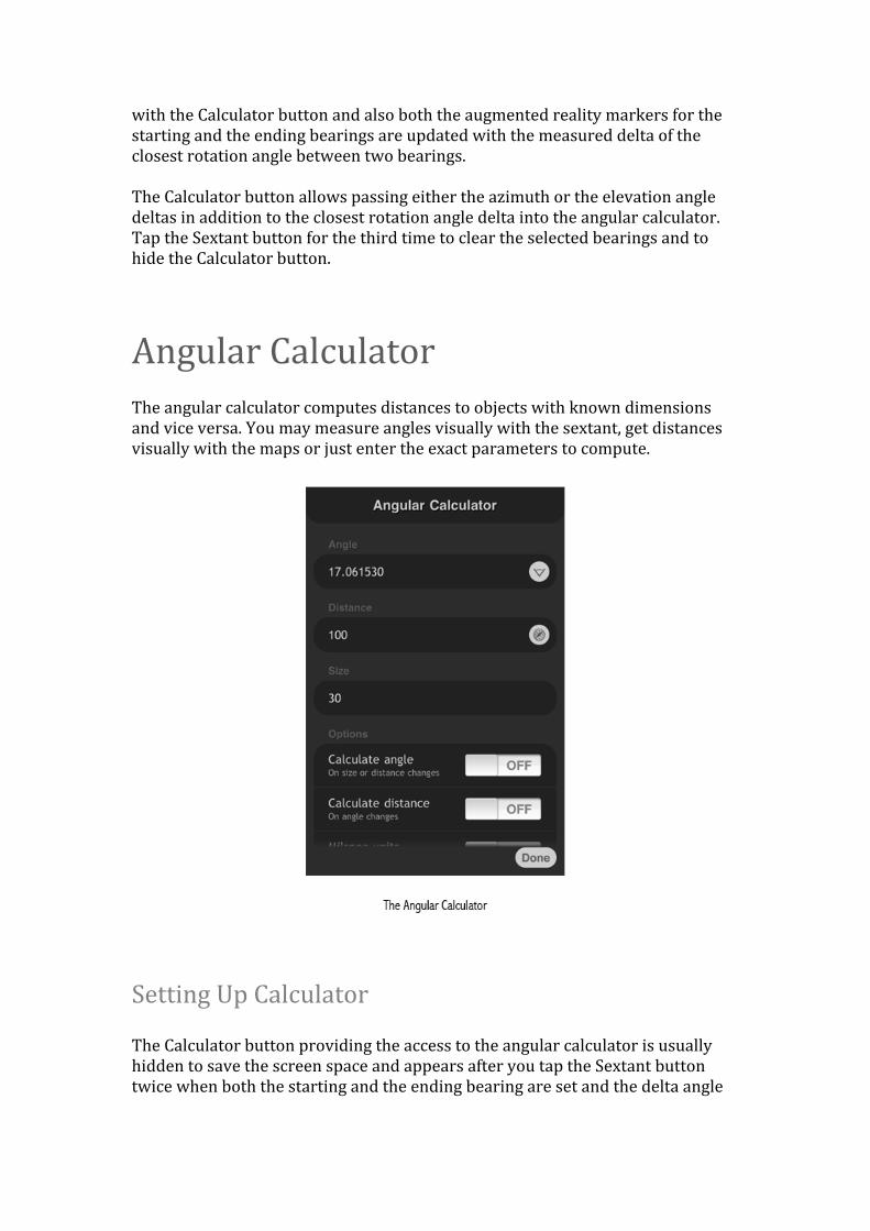
with the Calculator button and also both the augmented reality markers for the starting and the ending bearings are updated with the measured delta of the closest rotation angle between two bearings.
The Calculator button allows passing either the azimuth or the elevation angle deltas in addition to the closest rotation angle delta into the angular calculator. Tap the Sextant button for the third time to clear the selected bearings and to hide the Calculator button.
Angular CalculatorThe angular calculator computes distances to objects with known dimensions and vice versa. You may measure angles visually with the sextant, get distances visually with the maps or just enter the exact parameters to compute.
Setting Up Calculator
The Calculator button providing the access to the angular calculator is usually hidden to save the screen space and appears after you tap the Sextant button twice when both the starting and the ending bearing are set and the delta angle
between them is measured — to access the angular calculator you may set any two bearings with the Sextant button.
To set the current calculation type as per current needs or turn the military angular units on or off scroll to Options section within the angular calculator screen.
The calculation is independent of the units used — whether the metric meters or the imperial feet are used for the distance the size is computed in the same units and vice versa.
You may also want to switch into the manual mode of the orientation of the compass to ignore the rotation about gravity when visually measuring vertical angles with the sextant or into the gyrocompass mode when measuring other angles to get the best accuracy.
When measuring building and mountain heights you may also want to manually set the current location to achieve the best precision of the augmented reality mapping and to get the best accuracy of the visual distance measuring with the maps.
Calculating Object Distances
To calculate the distance to the object with the known angle and the known size scroll to the Options section, turn off Calculate angle switch, turn on Calculate distance switch and then type the angle and the size into the form — the object distance updates along with the angle and the size changes.
Calculating Object Dimensions
To calculate the size of the object with the known angle and the known distance scroll to the Options section, turn off Calculate angle switch, turn off Calculate distance switch and then type the angle and the distance into the form — the object size updates along with the angle and the distance changes.
Getting Angle Deltas From Sextant
In addition to the ability to pass the delta angles measured visually with the sextant you may tap the Sextant button next to the angle entry Vield within the angular calculator form to measure a new delta angle — when the measurement of the angle completes after tapping the Sextant button within the HUD twice the
measured angle is passed back into the angular calculator form at once without tapping the Calculator button.
Getting Object Distances with Maps
When online the maps may be used to visually measure the distance to the object in sight in order to calculate the size of the object after measuring the delta angle. The distance measured with the maps is either in meters or feet, depending on the units conVigured in the app settings.
Note: The coordinates of the current location are necessary in order to use the maps to visually measure distances. Otherwise, the Compass button doesn’t appear next to the distance entry Vield — you may need to set the location by hand then.
Measuring Building and Mountain Heights
To calculate the height of a building or a mountain by visually measuring the angle and the distance Virst set up the angular calculator to measure object dimensions.
You may also set your current location by hand for best precision though the horizontal accuracy is quite high outdoors — the closer the building the higher the deviation thus extra precision may be necessary when measuring distances to the closest objects with the maps.
Then measure the angle between the lowest point at the building basement and the top most upper point at the edge of the building roof with the sextant and then tap the Calculator button to pass the measured delta angle into the angular calculator form.
To get the distance to the building with the maps tap the Compass button next to the distance entry Vield within the angular calculator form and measure the distance to the building by centering the maps at the closest edge or a wall of the building as it appears on the maps.
The distance to the building is measured in either meters or feet and passed to the angular calculator form that instantly updates the size of the object — the height of the building is now computed in meters or feet, depending on units conVigured in the app settings.
InclinometerThe inclinometer measures azimuth (yaw), elevation (pitch) and horizon (roll) angle deltas. You may just read the rotation angles from the corresponding HUD elements or use the sextant to calculate deltas.
Measuring Angles and Angle Deltas
The inclinometer measures angles referring to the horizon plane.
The azimuth or the yaw angle measures the rotation about gravity — measuring the azimuth is only available on the devices with either the built-‐in hardware digital compass sensor or the built-‐in hardware rotation sensor.
To feel the horizontal rotations of the device either the built-‐in magnetometer or the built-‐in gyroscope are required — otherwise the current azimuth angle may be set either manually by hand or with the course of the movement, depending on the current mode of the orientation of the compass.
The horizon or the roll angle depends on the current device orientation and shows how much the device is rotated left of right — the angle is limited up to 45° in both directions — lock the orientation of the device to measure bigger angles.
The elevation or the pitch angle shows how much the device is rotated forth or aft and equals to the angle between the direction of the camera sight and the plane of the horizon.
CameraThe camera allows you to take pictures or screenshots overlaid with the heads-‐up display and all the information on it. Pictures are stored into the Camera Roll.
Taking Pictures and Capturing Screenshots
To take a picture from the camera or to make a screenshot tap either the Camera button or use the combination of the Power and the Home buttons of the device pressed in the same time — the taken pictures and screenshots are added to the Camera Roll album.
Precision and AccuracyThe precision of the readings of the built-‐in hardware sensors affects all of the Spyglass features. Spyglass averages the input from the sensors over time and uses the basic motion dampening in order to achieve a better precision.
The gyroscope when present on the device is used to track the gravity instead of the accelerometer. To overcome issues with the magnetometer you may switch the compass into the gyrocompass mode. Also to get the best accuracy of the vertical angle measuring the manual compass orientation mode can be used to ignore the rotation about gravity.
The best GPS accuracy is only available outdoors — to overcome issues with the horizontal GPS accuracy and the accuracy of the magnetometer you may set the current location coordinates by hand and switch the compass into the gyrocompass mode.
Hints
Measuring Distances Between Map Points
You may measure the distance between two locations with the built-‐in maps.
To measure the distance between two points with the maps Virst set the current location coordinates manually to the coordinates of the Virst location — tap the Info button, select Location and choose the coordinates by centering the maps at the Virst point. Then open the manual location selection maps view and navigate to the second point — the distance between two points appears and updates as you pan and scroll the maps.
The shortest distance between two locations is measured when the navigation along the rhumb lines is turned off. Otherwise, the distance measured is the path length along the rhumb line between the points.
Troubleshooting
Compass Doesn’t Appear
Don’t forget to enable Location Services on your device.
Compass Arrow Always Points North
Don’t forget to enable Location Services on your device.
Camera Doesn’t Work
Double tap anywhere within the HUD and choose Camera to turn the camera on.
Note: On some devices, the camera is not available.
F.A.Q.
Flower Icon at Lock Screen?
The Vlower icon has nothing to do with Spyglass — the small picture fame icon image appears at the device lock screen when there is at least one picture stored into one of the photo albums on the device.