Embed Size (px)
Citation preview
GB
1
85464369036000 ©SANYO 2007 SANYO Electric Co., Ltd. Gunma, Japan
– DC INVERTER Air Conditioner –
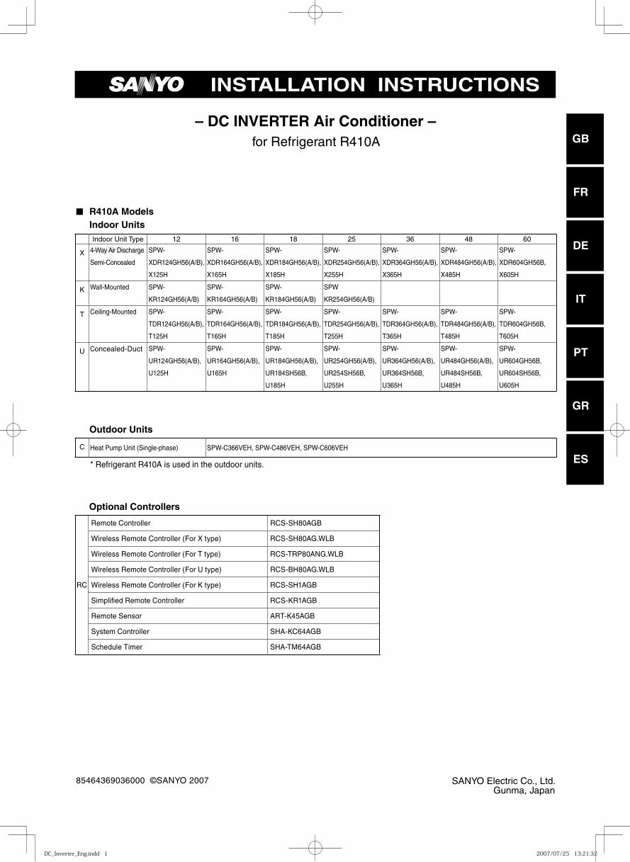
■ R410A Models Indoor Units
Outdoor Units
Optional Controllers
for Refrigerant R410A
INSTALLATION INSTRUCTIONS
FR
DE
IT
PT
GR
ES
Indoor Unit Type 12 16 18 25 36 48 60
X 4-Way Air Discharge
Semi-Concealed
SPW-
XDR124GH56(A/B),
X125H
SPW-
XDR164GH56(A/B),
X165H
SPW-
XDR184GH56(A/B),
X185H
SPW-
XDR254GH56(A/B),
X255H
SPW-
XDR364GH56(A/B),
X365H
SPW-
XDR484GH56(A/B),
X485H
SPW-
XDR604GH56B,
X605H
K Wall-Mounted SPW-
KR124GH56(A/B)
SPW-
KR164GH56(A/B)
SPW-
KR184GH56(A/B)
SPW
KR254GH56(A/B)
T Ceiling-Mounted SPW-
TDR124GH56(A/B),
T125H
SPW-
TDR164GH56(A/B),
T165H
SPW-
TDR184GH56(A/B),
T185H
SPW-
TDR254GH56(A/B),
T255H
SPW-
TDR364GH56(A/B),
T365H
SPW-
TDR484GH56(A/B),
T485H
SPW-
TDR604GH56B,
T605H
U Concealed-Duct SPW-
UR124GH56(A/B),
U125H
SPW-
UR164GH56(A/B),
U165H
SPW-
UR184GH56(A/B),
UR184SH56B,
U185H
SPW-
UR254GH56(A/B),
UR254SH56B,
U255H
SPW-
UR364GH56(A/B),
UR364SH56B,
U365H
SPW-
UR484GH56(A/B),
UR484SH56B,
U485H
SPW-
UR604GH56B,
UR604SH56B,
U605H
C Heat Pump Unit (Single-phase) SPW-C366VEH, SPW-C486VEH, SPW-C606VEH
* Refrigerant R410A is used in the outdoor units.
RC
Remote Controller RCS-SH80AGB
Wireless Remote Controller (For X type) RCS-SH80AG.WLB
Wireless Remote Controller (For T type) RCS-TRP80ANG.WLB
Wireless Remote Controller (For U type) RCS-BH80AG.WLB
Wireless Remote Controller (For K type) RCS-SH1AGB
Simplifi ed Remote Controller RCS-KR1AGB
Remote Sensor ART-K45AGB
System Controller SHA-KC64AGB
Schedule Timer SHA-TM64AGB
DC_Inverter_Eng.indd 1DC_Inverter_Eng.indd 1 2007/07/25 13:21:322007/07/25 13:21:32
GB
FR
DE
IT
PT
GR
ES
2
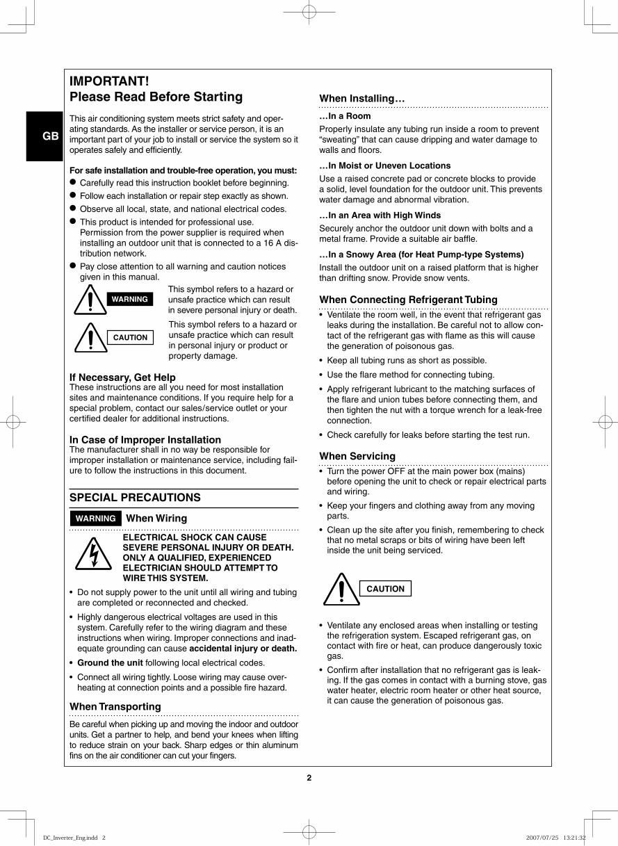
IMPORTANT! Please Read Before Starting
This air conditioning system meets strict safety and oper-ating standards. As the installer or service person, it is an important part of your job to install or service the system so it operates safely and efficiently.
For safe installation and trouble-free operation, you must:● Carefully read this instruction booklet before beginning.● Follow each installation or repair step exactly as shown.● Observe all local, state, and national electrical codes.● This product is intended for professional use.
Permission from the power supplier is required when installing an outdoor unit that is connected to a 16 A dis-tribution network.
● Pay close attention to all warning and caution notices given in this manual.
This symbol refers to a hazard or unsafe practice which can result in severe personal injury or death.
This symbol refers to a hazard or unsafe practice which can result in personal injury or product or property damage.
If Necessary, Get HelpThese instructions are all you need for most installation sites and maintenance conditions. If you require help for a special problem, contact our sales/service outlet or your certified dealer for additional instructions.
In Case of Improper InstallationThe manufacturer shall in no way be responsible for improper installation or maintenance service, including fail-ure to follow the instructions in this document.
SPECIAL PRECAUTIONS
WARNING When Wiring
ELECTRICAL SHOCK CAN CAUSE SEVERE PERSONAL INJURY OR DEATH. ONLY A QUALIFIED, EXPERIENCED ELECTRICIAN SHOULD ATTEMPT TO WIRE THIS SYSTEM.
• Do not supply power to the unit until all wiring and tubing are completed or reconnected and checked.
• Highly dangerous electrical voltages are used in this system. Carefully refer to the wiring diagram and these instructions when wiring. Improper connections and inad-equate grounding can cause accidental injury or death.
• Ground the unit following local electrical codes.
• Connect all wiring tightly. Loose wiring may cause over-heating at connection points and a possible fire hazard.
When Transporting
Be careful when picking up and moving the indoor and outdoor units. Get a partner to help, and bend your knees when lifting to reduce strain on your back. Sharp edges or thin aluminum fins on the air conditioner can cut your fingers.
When Installing…
…In a Room
Properly insulate any tubing run inside a room to prevent “sweating” that can cause dripping and water damage to walls and floors.
…In Moist or Uneven Locations
Use a raised concrete pad or concrete blocks to provide a solid, level foundation for the outdoor unit. This prevents water damage and abnormal vibration.
…In an Area with High Winds
Securely anchor the outdoor unit down with bolts and a metal frame. Provide a suitable air baffle.
…In a Snowy Area (for Heat Pump-type Systems)
Install the outdoor unit on a raised platform that is higher than drifting snow. Provide snow vents.
When Connecting Refrigerant Tubing• Ventilate the room well, in the event that refrigerant gas
leaks during the installation. Be careful not to allow con-tact of the refrigerant gas with flame as this will cause the generation of poisonous gas.
• Keep all tubing runs as short as possible.
• Use the flare method for connecting tubing.
• Apply refrigerant lubricant to the matching surfaces of the flare and union tubes before connecting them, and then tighten the nut with a torque wrench for a leak-free connection.
• Check carefully for leaks before starting the test run.
When Servicing• Turn the power OFF at the main power box (mains)
before opening the unit to check or repair electrical parts and wiring.
• Keep your fingers and clothing away from any moving parts.
• Clean up the site after you finish, remembering to check that no metal scraps or bits of wiring have been left inside the unit being serviced.
• Ventilate any enclosed areas when installing or testing the refrigeration system. Escaped refrigerant gas, on contact with fire or heat, can produce dangerously toxic gas.
• Confirm after installation that no refrigerant gas is leak-ing. If the gas comes in contact with a burning stove, gas water heater, electric room heater or other heat source, it can cause the generation of poisonous gas.
WARNING
CAUTION
CAUTION
DC_Inverter_Eng.indd 2DC_Inverter_Eng.indd 2 2007/07/25 13:21:322007/07/25 13:21:32
GB
FR
DE
IT
PT
GR
ES
3
2. The standards for minimum room volume are as follows.
(1) No partition (shaded portion)
(2) When there is an effective opening with the adjacent room for ventilation of leaking refrigerant gas (opening without a door, or an opening 0.15% or larger than the respective floor spaces at the top or bottom of the door).
(3) If an indoor unit is installed in each partitioned room and the refrigerant tubing is interconnected, the smallest room of course becomes the object. But when mechanical ventilation is installed interlocked with a gas leakage detector in the smallest room where the density limit is exceeded, the volume of the next smallest room becomes the object.
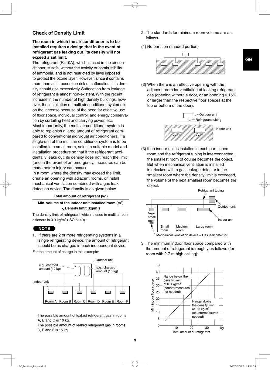
3. The minimum indoor floor space compared with the amount of refrigerant is roughly as follows (for room with 2.7 m high ceiling):
Check of Density Limit
The room in which the air conditioner is to be installed requires a design that in the event of refrigerant gas leaking out, its density will not exceed a set limit.The refrigerant (R410A), which is used in the air con-ditioner, is safe, without the toxicity or combustibility of ammonia, and is not restricted by laws imposed to protect the ozone layer. However, since it contains more than air, it poses the risk of suffocation if its den-sity should rise excessively. Suffocation from leakage of refrigerant is almost non-existent. With the recent increase in the number of high density buildings, how-ever, the installation of multi air conditioner systems is on the increase because of the need for effective use of floor space, individual control, and energy conserva-tion by curtailing heat and carrying power, etc.Most importantly, the multi air conditioner system is able to replenish a large amount of refrigerant com-pared to conventional individual air conditioners. If a single unit of the multi air conditioner system is to be installed in a small room, select a suitable model and installation procedure so that if the refrigerant acci-dentally leaks out, its density does not reach the limit (and in the event of an emergency, measures can be made before injury can occur).In a room where the density may exceed the limit, create an opening with adjacent rooms, or install mechanical ventilation combined with a gas leak detection device. The density is as given below.
Total amount of refrigerant (kg)
Min. volume of the indoor unit installed room (m3) < Density limit (kg/m3)
The density limit of refrigerant which is used in multi air con-ditioners is 0.3 kg/m3 (ISO 5149).
NOTE
1. If there are 2 or more refrigerating systems in a single refrigerating device, the amount of refrigerant should be as charged in each independent device.
For the amount of charge in this example:
The possible amount of leaked refrigerant gas in rooms A, B and C is 10 kg.The possible amount of leaked refrigerant gas in rooms D, E and F is 15 kg.
Outdoor unit
Refrigerant tubing
Indoor unit
e.g., charged amount (10 kg)
Outdoor unit
Indoor unit
Room A Room B Room C Room D Room E Room F
e.g., charged amount (15 kg)
Refrigerant tubing
Outdoor unit
Very small room Indoor unit
Small room
Medium room
Large room
Mechanical ventilation device – Gas leak detector
40
35
30
25
20
15
10
5
010 20 30
Total amount of refrigerant
Min
. ind
oor
floor
spa
ce
m2
kg
Range below the density limit of 0.3 kg/m3
(countermeasures not needed)
Range above the density limit of 0.3 kg/m3
(countermeasures needed)
DC_Inverter_Eng.indd 3DC_Inverter_Eng.indd 3 2007/07/25 13:21:332007/07/25 13:21:33
GB
FR
DE
IT
PT
GR
ES
4
1-2. Prevent impurities including water, dust and oxide from entering the tubing. Impurities can cause R410A refrig-erant deterioration and compressor defects. Due to the features of the refrigerant and refrigerating machine oil, the prevention of water and other impurities becomes more important than ever.
2. Be sure to recharge the refrigerant only in liquid form.
2-1. Since R410A is a non-azeotrope, recharging the refrigerant in gas form can lower performance and cause defects of the unit.
2-2. Since refrigerant composition changes and performance decreases when gas leaks, collect the remaining refrigerant and recharge the required total amount of new refrigerant after fixing the leak.
3. Different tools required
3-1. Tool specifications have been changed due to the characteristics of R410A. Some tools for R22- and R407C-type refrigerant systems cannot be used.
Unit: mm
Material O
Copper tube Outer diameter 6.35 9.52 12.7 15.88
Wall thickness 0.8 0.8 0.8 1.0
Precautions for Installation Using New Refrigerant
1. Care regarding tubing
1-1. Process tubing
● Material: Use C1220 phosphorous deoxidized copper specified in JIS H3300 “Copper and Copper Alloy Seam-less Pipes and Tubes”.
● Tubing size: Be sure to use the sizes indicated in the table below.● Use a tube cutter when cutting the tubing, and be sure to remove any flash. This also applies to distribution joints
(optional).● When bending tubing ø15.88 or smaller, use a bending radius that is 4 times the outer diameter of the tubing or larger.
* Using tools for R22 and R407C and new tools for R410A together can cause defects.
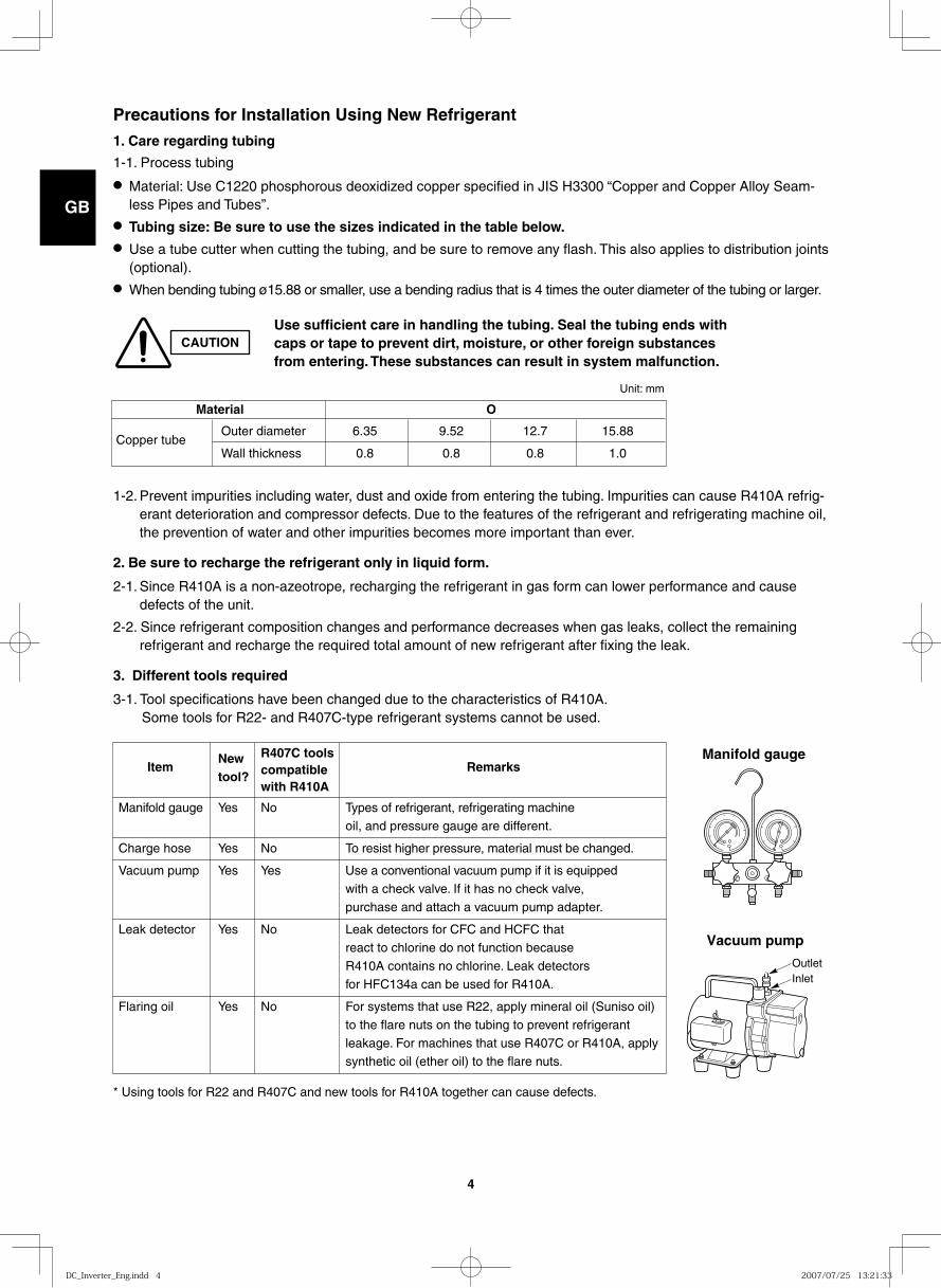
Manifold gauge
Vacuum pump
OutletInlet
New
R407C tools Item
tool? compatible Remarks
with R410A
Manifold gauge Yes No Types of refrigerant, refrigerating machine oil, and pressure gauge are different.
Charge hose Yes No To resist higher pressure, material must be changed.
Vacuum pump Yes Yes Use a conventional vacuum pump if it is equipped with a check valve. If it has no check valve, purchase and attach a vacuum pump adapter.
Leak detector Yes No Leak detectors for CFC and HCFC that react to chlorine do not function because R410A contains no chlorine. Leak detectors for HFC134a can be used for R410A.
Flaring oil Yes No For systems that use R22, apply mineral oil (Suniso oil) to the flare nuts on the tubing to prevent refrigerant leakage. For machines that use R407C or R410A, apply synthetic oil (ether oil) to the flare nuts.
CAUTIONUse sufficient care in handling the tubing. Seal the tubing ends with caps or tape to prevent dirt, moisture, or other foreign substances from entering. These substances can result in system malfunction.
DC_Inverter_Eng.indd 4DC_Inverter_Eng.indd 4 2007/07/25 13:21:332007/07/25 13:21:33
GB
FR
DE
IT
PT
GR
ES
5
Valve
Liquid
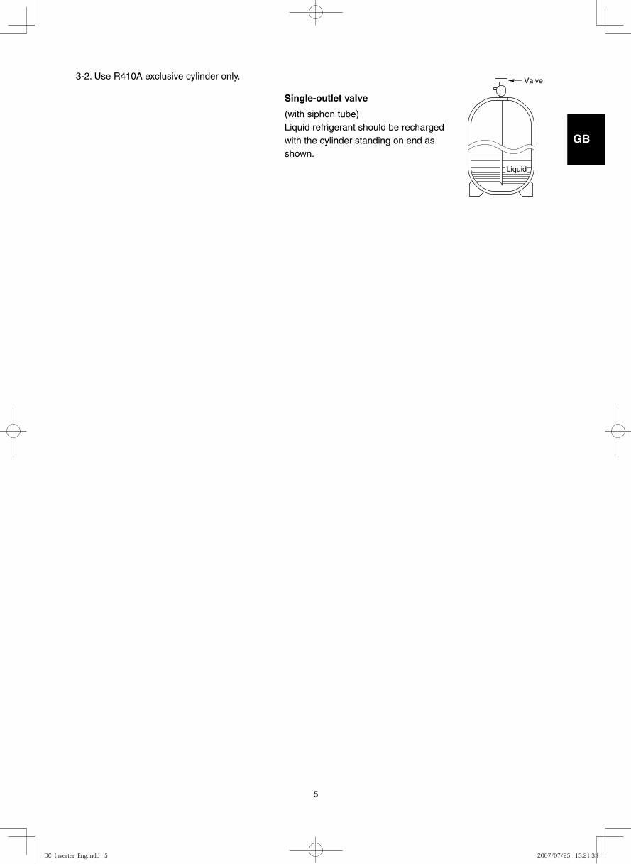
3-2. Use R410A exclusive cylinder only.
Single-outlet valve
(with siphon tube)Liquid refrigerant should be recharged with the cylinder standing on end as shown.
DC_Inverter_Eng.indd 5DC_Inverter_Eng.indd 5 2007/07/25 13:21:332007/07/25 13:21:33
GB
FR
DE
IT
PT
GR
ES
6
IMPORTANT . . . . . . . . . . . . . . . . . . . . . . . . . . . . . . 2Please Read Before StartingCheck of Density LimitPrecautions for Installation Using New Refrigerant
1. GENERAL . . . . . . . . . . . . . . . . . . . . . . . . . . . . . 81-1. Tools Required for Installation (not supplied)1-2. Accessories Supplied with Unit1-3. Type of Copper Tube and Insulation Material1-4. Additional Materials Required for Installation1-5. Tubing Size1-6. Optional Distribution Joint Kits1-7. Installing Distribution Joint Kit (for Twin &
Double-Twin) (APR-P160BG)1-8. Installing Distribution Joint Kit (for Triple)
(APR-RTP280AGB)
2. SELECTING THE INSTALLATION SITE . . . . . 172-1. Indoor Unit2-2. Outdoor Unit2-3. Air Discharge Chamber for Top Discharge2-4. Installing the Unit in Heavy Snow Areas2-5. Precautions for Installation in Heavy Snow
Areas2-6. Dimensions of Snow / Wind-proof Ducting
and Refrigerant Tubing Space of Installation
3. HOW TO INSTALL THE INDOOR UNIT . . . . . . 20
■ 4-Way Air Discharge Semi-Concealed Type (X Type) . . . . . . . . . . . . . . . . . . . . . . . . . . . . . . 203-1. Preparation for Ceiling Suspension 3-2. Mounting the Suspension Bolts3-3. Placing the Unit Inside the Ceiling 3-4. Installing the Drain Pipe3-5. Checking the Drainage
■ Wall-Mounted Type (K Type) . . . . . . . . . . . . . . . 243-6. Removing the Rear Panel from the Unit3-7. Selecting and Making a Hole3-8. Attaching the Rear Panel onto the Wall3-9. Removing the Grille to Install the Indoor Unit3-10. Preparing the Tubing 3-11. Shaping the Tubing3-12. Installing the Drain Hose
■ Ceiling-Mounted Type (T Type) . . . . . . . . . . . . . 283-13. Required Minimum Space for Installation and
Service3-14. Suspending the Indoor Unit3-15. Duct for Fresh Air3-16. Shaping the Tubing3-17. Installing the Drain Pipe
■ Concealed-Duct Type (U Type) . . . . . . . . . . . . 353-18. Required Minimum Space for Installation and
Service
3-19. Suspending the Indoor Unit 3-20. Installing the Drain Pipe 3-21. Checking the Drainage 3-22. Increasing the Fan Speed
4. HOW TO INSTALL THE OUTDOOR UNIT . . . . 424-1. Installing the Outdoor Unit4-2. Drainage Work4-3. Routing the Tubing and Wiring
5. ELECTRICAL WIRING . . . . . . . . . . . . . . . . . . . 435-1. General Precautions on Wiring 5-2. Recommended Wire Length and Wire
Diameter for Power Supply System 5-3. Wiring System Diagrams
6. HOW TO INSTALL THE REMOTE CONTROLLER (OPTIONAL PART) . . . . . . . . . . . . . . . . . . . . . . 47
6-1. When Using a Wall Box for Flush Mounting 6-2. Basic Wiring Diagram
(Twin, Triple, Double-Twin)6-3. Wiring System Diagram for Group Control 6-4. Switching the Room Temperature Sensors6-5. Connecting to a Ventilation Fan6-6. Wiring the Remote Controller6-7. Trouble Diagnostics
7. HOW TO PROCESS TUBING . . . . . . . . . . . . . 557-1. Connecting the Refrigerant Tubing7-2. Connecting Tubing Between Indoor and
Outdoor Units7-3. Insulating the Refrigerant Tubing7-4. Taping the Tubes7-5. Finishing the Installation
8. LEAK TEST, EVACUATION AND ADDITIONAL REFRIGERANT CHARGE . . . . . . . . . . . . . . . . 59
■ Air Purging with a Vacuum Pump (for Test Run) Preparation . . . . . . . . . . . . . . . . . . . . . . . . . . . . 598-1. Leak Test8-2. Evacuation8-3. Charging Additional Refrigerant8-4. Finishing the Job
9. HOW TO INSTALL THE CEILING PANEL . . . . 62
■ 4-Way Air Discharge Semi-Concealed Type (X Type) . . . . . . . . . . . . . . . . . . . . . . . . . . . . . . 629-1. Before Installing the Ceiling Panel 9-2. Installing the Ceiling Panel 9-3. Wiring the Ceiling Panel9-4. How to Attach the Corner & Air Intake Grille9-5. Checking After Installation9-6. When Removing the Ceiling Panel for Servicing9-7. Adjusting the Auto Flap
CONTENTS
Page Page
DC_Inverter_Eng.indd 6DC_Inverter_Eng.indd 6 2007/07/25 13:21:332007/07/25 13:21:33
GB
FR
DE
IT
PT
GR
ES
7
10. TEST RUN . . . . . . . . . . . . . . . . . . . . . . . . . . . 6610-1. Preparing for Test Run
■ X, T, U Type . . . . . . . . . . . . . . . . . . . . . . . . . . . 6710-2. Caution10-3. Test Run Procedure10-4. Items to Check Before the Test Run10-5. Test Run Using the Remote Controller10-6. Precautions10-7. Table of Self-Diagnostic Functions and
Corrections (X, T, U, K Type)10-8. System Control
■ K Type . . . . . . . . . . . . . . . . . . . . . . . . . . . . . . . 7510-9. Caution10-10. Test Run Procedure10-11. Items to Check Before the Test Run10-12. Preparation for Test Run10-13. Test Run10-14. Precautions10-15. Table of Self-Diagnostic Functions and
Corrections 10-16. System Control
■ X, T, U Type (for Link Wiring) . . . . . . . . . . . . . . 8610-17. Caution10-18. Test Run Procedure10-19. Items to Check Before the Test Run10-20. Test Run Using the Remote Controller10-21. Table of Self-Diagnostic Functions and
Corrections X, T, U, K Type10-22. Automatic Address Setting
■ K Type (for Link Wiring) . . . . . . . . . . . . . . . . . . 9510-23. Caution10-24. Test Run Procedure10-25. Table of Self-Diagnostic Functions and
Corrections X, T, U, K Type10-26. Automatic Address Setting10-27. Caution for Pump Down
11. HOW TO INSTALL THE WIRELESS REMOTE CONTROLLER RECEIVER . . . . . . . . . . . . . 104
■ RCS-SH80AG.WLB for 4-Way Cassette (X Type) . . . . . . . . . . . . . . . . . . . . . . . . . . . . . 10411-1. Installing the Receiver Unit11-2. Accessories11-3. Wiring the Receiver Unit11-4. Precautions on Simultaneous Installation
of Wired Remote Controller and Wireless Remote Controller
11-5. How to Use the Test Run Setting
■ RCS-TRP80ANG.WLB for Ceiling Mounted (T Type) . . . . . . . . . . . . . . . . . . . . . . . . . . . . . 10711-6. Installing the Receiver Unit11-7. Accessories Supplied with Unit
11-8. Wiring the Receiver Unit11-9. Precautions on Simultaneous Installation
of Wired Remote Controller and Wireless Remote Controller
11-10. How to Use the Test Run Setting
■ RCS-BH80AG.WLB for U Type . . . . . . . . . . . . 11011-11. Accessories Supplied with Separate
Receiver Unit 11-12. Important Information for Installation of
1 Separate Receiver Unit11-13. How to Install the Separate Receiver Unit 11-14. Wiring the Separate Receiver Unit11-15. Important Information for Installation of
2 Separate Receiver Units11-16. Test Run Setting
12. MARKINGS FOR DIRECTIVE 97/23/EC (PED) . . . . . . . . . . . . . . . . . . . . . . 116
APPENDIX
■ French . . . . . . . . . . . . . . . . . . . . . . . . . . . . . . 117
■ German . . . . . . . . . . . . . . . . . . . . . . . . . . . . . 147
■ Italian . . . . . . . . . . . . . . . . . . . . . . . . . . . . . . . 177
■ Portuguese . . . . . . . . . . . . . . . . . . . . . . . . . . . 207
■ Greek . . . . . . . . . . . . . . . . . . . . . . . . . . . . . . . 237
■ Spanish . . . . . . . . . . . . . . . . . . . . . . . . . . . . . 267
Page
DC_Inverter_Eng.indd 7DC_Inverter_Eng.indd 7 2007/07/25 13:21:342007/07/25 13:21:34
GB
FR
DE
IT
PT
GR
ES
8
1. GENERAL
This booklet briefly outlines where and how to install the air conditioning system. Please read over the entire set of instructions for the indoor and outdoor units and make sure all accessory parts listed are with the system before beginning.
1-1. Tools Required for Installation (not supplied) 1. Standard screwdriver 2. Phillips head screwdriver 3. Knife or wire stripper 4. Tape measure 5. Carpenter’s level 6. Sabre saw or key hole saw 7. Hacksaw 8. Core bits 9. Hammer 10. Drill 11. Tube cutter 12. Tube flaring tool 13. Torque wrench 14. Adjustable wrench 15. Reamer (for deburring)
1-2. Accessories Supplied with Unit
See Tables 1-1 to 1-4.
1-3. Type of Copper Tube and Insulation Material
If you wish to purchase these materials separately from a local source, you will need:
1. Deoxidized annealed copper tube for refrigerant tubing.
2. Foamed polyethylene insulation for copper tubes as required to precise length of tubing. Wall thickness of the insulation should be not less than 8 mm.
3. Use insulated copper wire for field wiring. Wire size varies with the total length of wiring. Refer to 5. Electrical Wiring for details.
1-4. Additional Materials Required for Installation
1. Refrigeration (armored) tape
2. Insulated staples or clamps for connecting wire (See your local codes.)
3. Putty
4. Refrigeration tubing lubricant
5. Clamps or saddles to secure refrigerant tubing
6. Scale for weighing
CAUTION Check local electrical codes and regulations before obtaining wire. Also, check any specified instructions or limitations.
Table Type
1-1 4-Way Air Discharge Semi-Concealed
1-2 Wall-Mounted
1-3 Ceiling-Mounted
1-4 Concealed-Duct
DC_Inverter_Eng.indd 8DC_Inverter_Eng.indd 8 2007/07/25 13:21:342007/07/25 13:21:34
GB
FR
DE
IT
PT
GR
ES
9
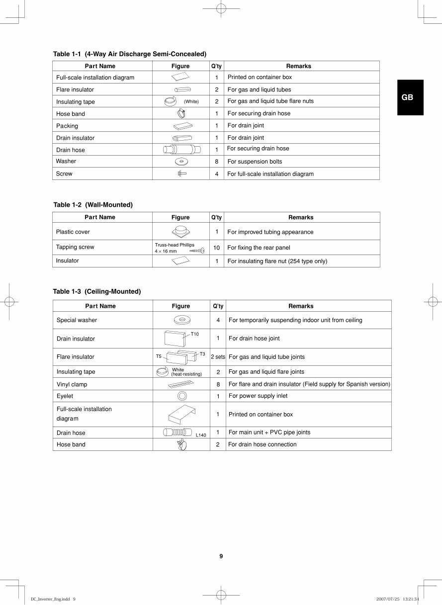
Table 1-1 (4-Way Air Discharge Semi-Concealed)
Part Name Figure Q’ty Remarks
Full-scale installation diagram 1
Flare insulator 2
Insulating tape 2
Hose band 1
Packing 1
Drain insulator 1
Drain hose 1
4
For gas and liquid tubes
For securing drain hose
For drain joint
For drain joint
(White)
Washer 8 For suspension bolts
Screw
Printed on container box
For gas and liquid tube flare nuts
For full-scale installation diagram
For securing drain hose
Table 1-2 (Wall-Mounted)
Part Name Figure Q’ty Remarks
Plastic cover 1
Tapping screw 10
For improved tubing appearance
For fixing the rear panelTruss-head Phillips4 × 16 mm
Insulator 1 For insulating flare nut (254 type only)
Table 1-3 (Ceiling-Mounted)
Part Name Figure Q’ty Remarks
Special washer 4
Drain insulator 1
Flare insulator 2 sets
Insulating tape 2
Vinyl clamp 8
Eyelet 1
Full-scale installation
diagram1
Drain hose 1
For temporarily suspending indoor unit from ceiling
For drain hose joint
For gas and liquid tube joints
For gas and liquid flare joints
For flare and drain insulator (Field supply for Spanish version)
For power supply inlet
T10
T5 T3
White(heat-resisting)
For drain hose connection2Hose band
L140 For main unit + PVC pipe joints
Printed on container box
DC_Inverter_Eng.indd 9DC_Inverter_Eng.indd 9 2007/07/25 13:21:342007/07/25 13:21:34
GB
FR
DE
IT
PT
GR
ES
10
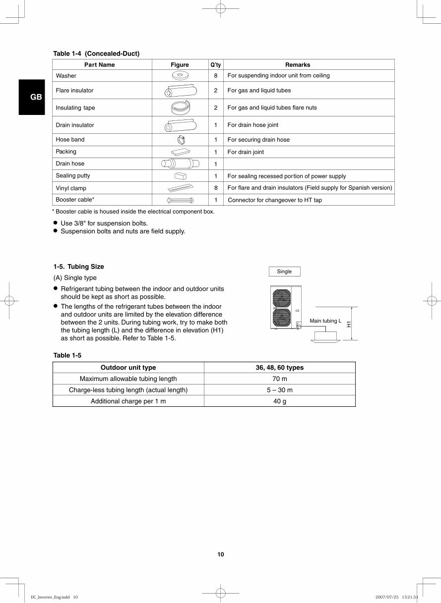
Table 1-4 (Concealed-Duct)
P a r t Name Figure Q’ty Remarks
8
Flare insulator 2
Insulating tape 2
Dr ain insulator 1
Hose band 1
P a c king 1
Dr ain hose 1
Sealing putty 1
Vin yl clamp 8
Booster cab le* 1
F or suspending indoor unit from ceiling
F or gas and liquid tubes
F or gas and liquid tubes flare nuts
F or drain hose joint
F or secur ing drain hose
F or drain joint
F or sealing recessed por tion of po wer supply
F or flare and drain insulators (Field supply for Spanish version)
* Booster cab le is housed inside the electr ical component bo x.
Washer
Connector for changeover to HT tap
● Use 3/8" for suspension bolts.● Suspension bolts and nuts are field supply.
1-5. Tubing Size
(A) Single type
● Refrigerant tubing between the indoor and outdoor units should be kept as short as possible.
● The lengths of the refrigerant tubes between the indoor and outdoor units are limited by the elevation difference between the 2 units. During tubing work, try to make both the tubing length (L) and the difference in elevation (H1) as short as possible. Refer to Table 1-5.
Table 1-5
Single
Main tubing L
H1
Outdoor unit type 36, 48, 60 types
Maximum allowable tubing length 70 m
Charge-less tubing length (actual length) 5 – 30 m
Additional charge per 1 m 40 g
DC_Inverter_Eng.indd 10DC_Inverter_Eng.indd 10 2007/07/25 13:21:342007/07/25 13:21:34
GB
FR
DE
IT
PT
GR
ES
11
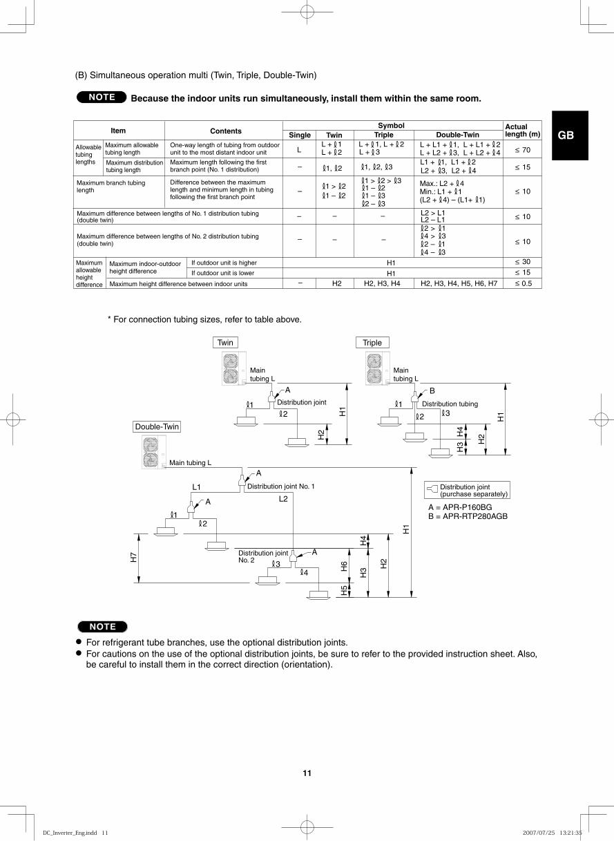
(B) Simultaneous operation multi (Twin, Triple, Double-Twin)
NOTE Because the indoor units run simultaneously, install them within the same room.
Single Twin Triple Double-TwinActual length (m)
LL + 1L + 2 L + 3
L + 1, L + 2 L + L1 + 1, L + L1 + 2
L2 + 3, L2 + 4
Max.: L2 + 4Min.: L1 + 1(L2 + 4) – (L1+ 1)
L1 + 1, L1 + 21, 2
1 > 21 > 2 > 3
1 – 21 – 21 – 32 – 3
L + L2 + 3, L + L2 + 4
1, 2, 3
70
15
10
10
30
15
0.5
Item Contents
Allowable tubing lengths
Maximum allowable tubing length
One-way length of tubing from outdoor unit to the most distant indoor unit
Maximum distribution tubing length
Maximum length following the first branch point (No. 1 distribution)
Maximum branch tubing length
Difference between the maximum length and minimum length in tubing following the first branch point
Maximum difference between lengths of No. 1 distribution tubing (double twin)
Maximum difference between lengths of No. 2 distribution tubing (double twin)
Maximum allowable height difference
Maximum indoor-outdoor height difference
If outdoor unit is higher
If outdoor unit is lower
Maximum height difference between indoor units
Symbol
L2 > L1
2 > 1 4 > 3 2 – 1 4 – 3
L2 – L1
H2 H2, H3, H4 H2, H3, H4, H5, H6, H7
–
–
– – –
–
–
– –
H1
H1
≥
≥
≥
≥
10≥
≥≥≥
TripleTwin
Main tubing L
Main tubing L
Main tubing L
Distribution joint No. 1 Distribution joint (purchase separately)
Distribution joint Distribution tubing
A
A
A
12 2
A
1
1
2
3
3
4
* For connection tubing sizes, refer to table above.
B
H1
H1
H1
H2
H2
H2 H4
H3
H3
H4
H6H
7
H5
Distribution joint No. 2
L1
L2A = APR-P160BGB = APR-RTP280AGB
Double-Twin
NOTE
● For refrigerant tube branches, use the optional distribution joints.● For cautions on the use of the optional distribution joints, be sure to refer to the provided instruction sheet. Also,
be careful to install them in the correct direction (orientation).
DC_Inverter_Eng.indd 11DC_Inverter_Eng.indd 11 2007/07/25 13:21:352007/07/25 13:21:35
GB
FR
DE
IT
PT
GR
ES
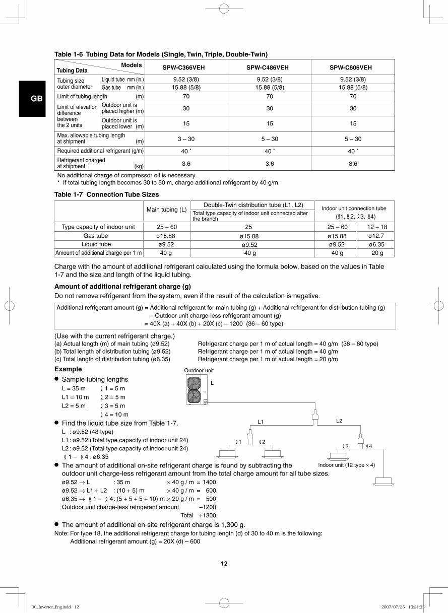
12
Tubing Data Models
Tubing size outer diameter
Liquid tube Gas tube
Limit of tubing length
Limit of elevation difference between the 2 units
Outdoor unit is placed higher
Outdoor unit is placed lower
Max. allowable tubing length at shipment
Required additional refrigerant
Refrigerant charged at shipment
SPW-C606VEHSPW-C366VEH SPW-C486VEH
mm (in.) mm (in.)
(m)
(m)
(m)
(m)
(g/m)
(kg)
9.52 (3/8)15.88 (5/8)
70
30
15
3 – 30
3.6
40 *
9.52 (3/8)15.88 (5/8)
70
30
15
5 – 30
3.6
40 *
9.52 (3/8)15.88 (5/8)
70
30
15
5 – 30
3.6
40 *
No additional charge of compressor oil is necessary.* If total tubing length becomes 30 to 50 m, charge additional refrigerant by 40 g/m.
Table 1-6 Tubing Data for Models (Single, Twin, Triple, Double-Twin)
25 – 6025 – 60 12 – 18
ø15.88ø15.88ø15.88ø9.52ø9.52ø9.52 ø6.35
ø12.7
( 1, 2, 3, 4)
20 g40 g40 g40 g
Gas tubeLiquid tube
Main tubing (L)
25
Double-Twin distribution tube (L1, L2)Total type capacity of indoor unit connected after the branch
Indoor unit connection tube
Type capacity of indoor unit
Amount of additional charge per 1 m
Table 1-7 Connection Tube Sizes
Charge with the amount of additional refrigerant calculated using the formula below, based on the values in Table 1-7 and the size and length of the liquid tubing.
Amount of additional refrigerant charge (g)Do not remove refrigerant from the system, even if the result of the calculation is negative.
(Use with the current refrigerant charge.)(a) Actual length (m) of main tubing (ø9.52) Refrigerant charge per 1 m of actual length = 40 g/m (36 – 60 type)(b) Total length of distribution tubing (ø9.52) Refrigerant charge per 1 m of actual length = 40 g/m(c) Total length of distribution tubing (ø6.35) Refrigerant charge per 1 m of actual length = 20 g/m
Example● Sample tubing lengths L = 35 m 1 = 5 m L1 = 10 m 2 = 5 m L2 = 5 m 3 = 5 m 4 = 10 m● Find the liquid tube size from Table 1-7. L : ø9.52 (48 type) L1 : ø9.52 (Total type capacity of indoor unit 24) L2 : ø9.52 (Total type capacity of indoor unit 24) 1 – 4 : ø6.35● The amount of additional on-site refrigerant charge is found by subtracting the
outdoor unit charge-less refrigerant amount from the total charge amount for all tube sizes. ø9.52 → L : 35 m × 40 g / m = 1400 ø9.52 → L1 + L2 : (10 + 5) m × 40 g / m = 600 ø6.35 → 1 – 4 : (5 + 5 + 5 + 10) m × 20 g / m = 500 Outdoor unit charge-less refrigerant amount –1200 Total +1300● The amount of additional on-site refrigerant charge is 1,300 g.Note: For type 18, the additional refrigerant charge for tubing length (d) of 30 to 40 m is the following: Additional refrigerant amount (g) = 20X (d) – 600
Outdoor unit
Indoor unit (12 type × 4)
L
L1 L2
4321
Additional refrigerant amount (g) = Additional refrigerant for main tubing (g) + Additional refrigerant for distribution tubing (g) – Outdoor unit charge-less refrigerant amount (g)
= 40X (a) + 40X (b) + 20X (c) – 1200 (36 – 60 type)
DC_Inverter_Eng.indd 12DC_Inverter_Eng.indd 12 2007/07/25 13:21:352007/07/25 13:21:35
GB
FR
DE
IT
PT
GR
ES
13
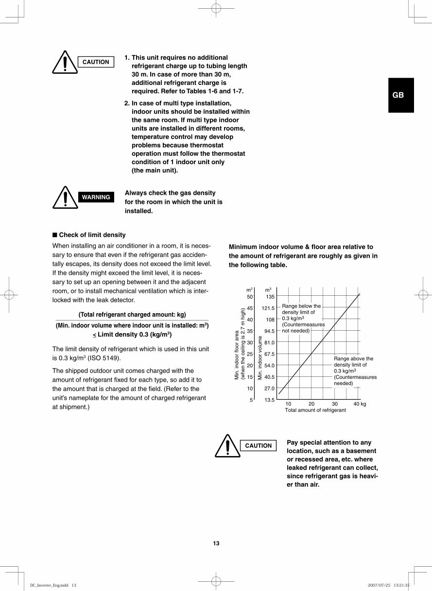
CAUTION1. This unit requires no additional
refrigerant charge up to tubing length 30 m. In case of more than 30 m, additional refrigerant charge is required. Refer to Tables 1-6 and 1-7.
2. In case of multi type installation, indoor units should be installed within the same room. If multi type indoor units are installed in different rooms, temperature control may develop problems because thermostat operation must follow the thermostat condition of 1 indoor unit only (the main unit).
WARNINGAlways check the gas density for the room in which the unit is installed.
CAUTION Pay special attention to any location, such as a basement or recessed area, etc. where leaked refrigerant can collect, since refrigerant gas is heavi-er than air.
1013.5
27.0
40.5
54.0
67.5
81.0
94.5
108
121.5
135
5
10
15
20
25
30
35
40
45
50m3m2
Total amount of refrigerant
Min
. ind
oor
floor
are
a(w
hen
the
ceili
ng is
2.7
m h
igh)
Min
. ind
oor
volu
me
20 30 40 kg
Range below thedensity limit of 0.3 kg/m3
(Countermeasuresnot needed)
Range above thedensity limit of 0.3 kg/m3
(Countermeasuresneeded)
■ Check of limit density
When installing an air conditioner in a room, it is neces-sary to ensure that even if the refrigerant gas acciden-tally escapes, its density does not exceed the limit level. If the density might exceed the limit level, it is neces-sary to set up an opening between it and the adjacent room, or to install mechanical ventilation which is inter-locked with the leak detector.
(Total refrigerant charged amount: kg)
(Min. indoor volume where indoor unit is installed: m3)< Limit density 0.3 (kg/m3)
The limit density of refrigerant which is used in this unit is 0.3 kg/m3 (ISO 5149).
The shipped outdoor unit comes charged with the amount of refrigerant fixed for each type, so add it to the amount that is charged at the field. (Refer to the unit’s nameplate for the amount of charged refrigerant at shipment.)
Minimum indoor volume & floor area relative to the amount of refrigerant are roughly as given in the following table.
DC_Inverter_Eng.indd 13DC_Inverter_Eng.indd 13 2007/07/25 13:21:352007/07/25 13:21:35
GB
FR
DE
IT
PT
GR
ES
14
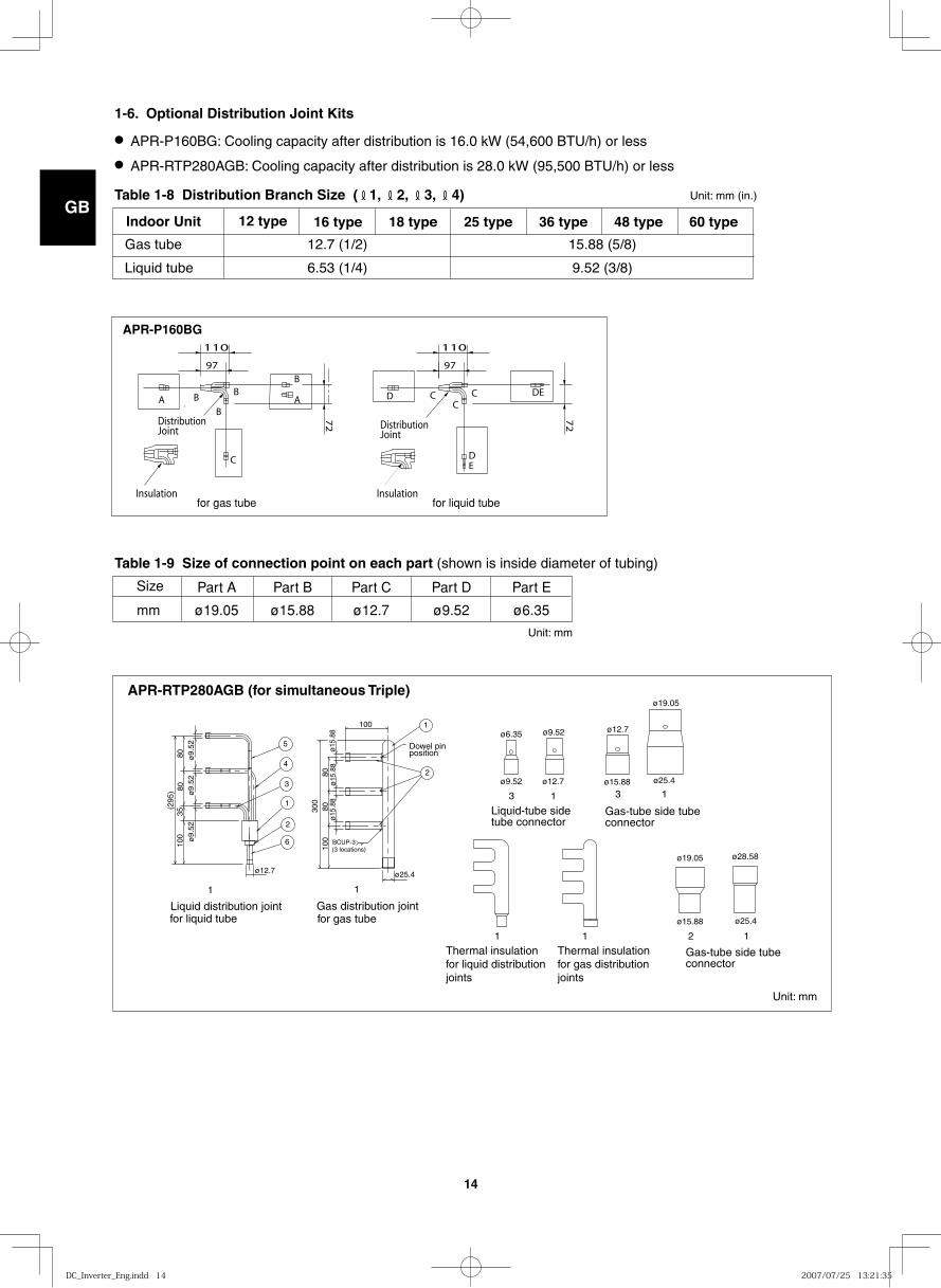
1-6. Optional Distribution Joint Kits
● APR-P160BG: Cooling capacity after distribution is 16.0 kW (54,600 BTU/h) or less
● APR-RTP280AGB: Cooling capacity after distribution is 28.0 kW (95,500 BTU/h) or less
Table 1-8 Distribution Branch Size ( 1, 2, 3, 4) Unit: mm (in.)
Indoor Unit 12 type 16 type 18 type 25 type 36 type 48 type 60 type
Gas tube 12.7 (1/2) 15.88 (5/8)
Liquid tube 6.53 (1/4) 9.52 (3/8)
for gas tube for liquid tube
APR-P160BG
B
B
B
C
Insulation
DistributionJoint
A
B
A
110
97
72
CC
C
ED
DE
Insulation
DistributionJoint
D
72
110
97
Table 1-9 Size of connection point on each part (shown is inside diameter of tubing)
Size Part A Part B Part C Part D Part E
mm ø19.05 ø15.88 ø12.7 ø9.52 ø6.35
100
3580
80(2
95)
ø9.
52ø
9.52
ø9.
52
1
2
1
2
3
4
5
6 BCUP-3
100
8080
300
100
ø12.7 ø25.4
ø15
.88
ø15
.88
ø15
.88
for liquid tube for gas tube
(3 locations)
Dowel pin position
Liquid distribution joint Gas distribution joint
Liquid-tube side tube connector
3 1 3 1
111 2
Gas-tube side tube connector
Gas-tube side tube connector
1 1
ø9.52 ø12.7
ø12.7
ø15.88
ø15.88
ø19.05
ø19.05
ø25.4
ø25.4
ø28.58
ø9.52ø6.35
Thermal insulation for liquid distribution joints
Thermal insulation for gas distribution joints
APR-RTP280AGB (for simultaneous Triple)
Unit: mm
Unit: mm
DC_Inverter_Eng.indd 14DC_Inverter_Eng.indd 14 2007/07/25 13:21:352007/07/25 13:21:35
GB
FR
DE
IT
PT
GR
ES
15
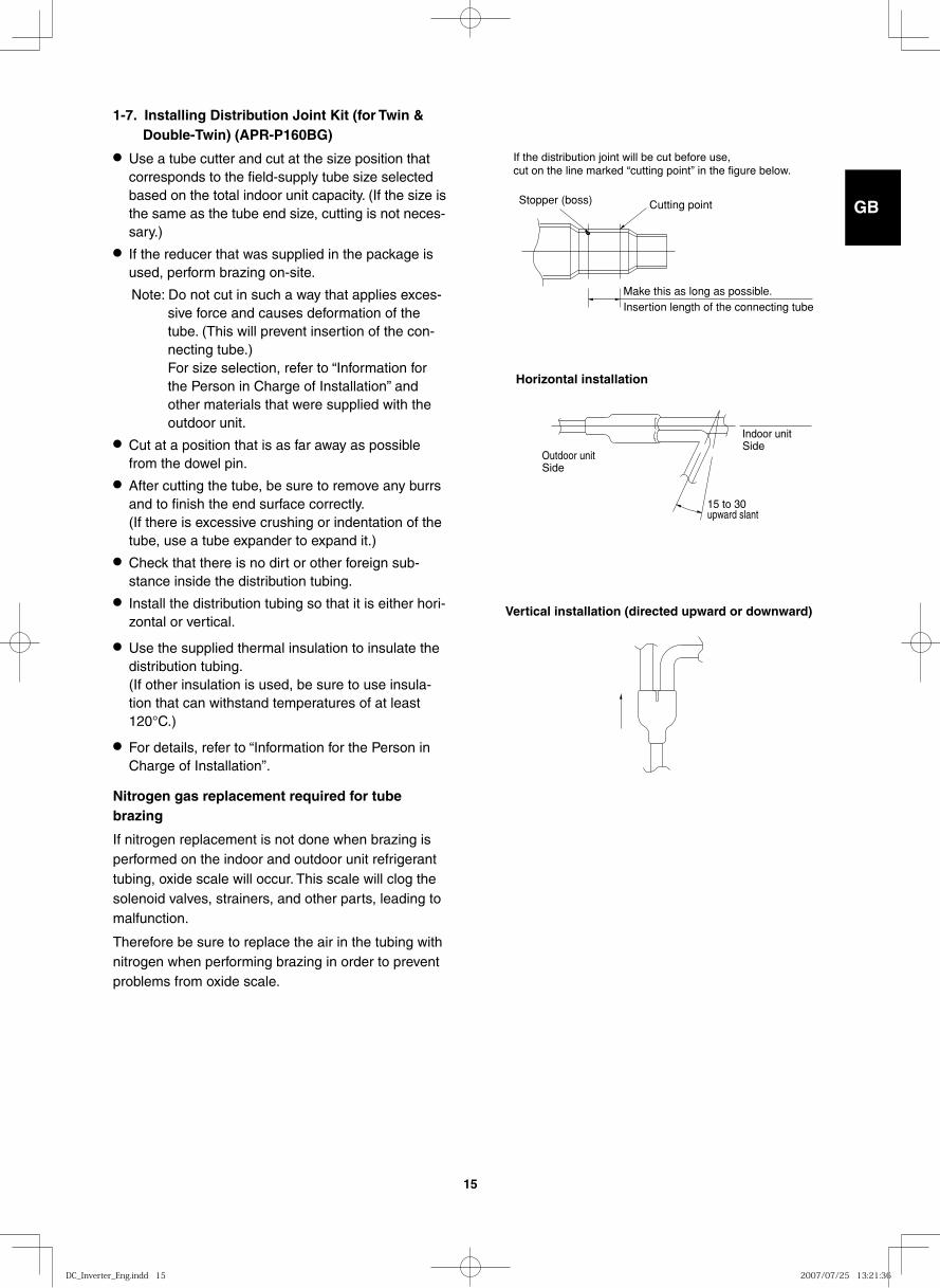
Cutting point
Insertion length of the connecting tubeMake this as long as possible.
Stopper (boss)
If the distribution joint will be cut before use,cut on the line marked “cutting point” in the figure below.
Vertical installation (directed upward or downward)
1-7. Installing Distribution Joint Kit (for Twin & Double-Twin) (APR-P160BG)
● Use a tube cutter and cut at the size position that corresponds to the field-supply tube size selected based on the total indoor unit capacity. (If the size is the same as the tube end size, cutting is not neces-sary.)
● If the reducer that was supplied in the package is used, perform brazing on-site.
Note: Do not cut in such a way that applies exces-sive force and causes deformation of the tube. (This will prevent insertion of the con-necting tube.) For size selection, refer to “Information for the Person in Charge of Installation” and other materials that were supplied with the outdoor unit.
● Cut at a position that is as far away as possible from the dowel pin.
● After cutting the tube, be sure to remove any burrs and to finish the end surface correctly. (If there is excessive crushing or indentation of the tube, use a tube expander to expand it.)
● Check that there is no dirt or other foreign sub-stance inside the distribution tubing.
● Install the distribution tubing so that it is either hori-zontal or vertical.
● Use the supplied thermal insulation to insulate the distribution tubing. (If other insulation is used, be sure to use insula-tion that can withstand temperatures of at least 120°C.)
● For details, refer to “Information for the Person in Charge of Installation”.
Nitrogen gas replacement required for tube brazing
If nitrogen replacement is not done when brazing is performed on the indoor and outdoor unit refrigerant tubing, oxide scale will occur. This scale will clog the solenoid valves, strainers, and other parts, leading to malfunction.
Therefore be sure to replace the air in the tubing with nitrogen when performing brazing in order to prevent problems from oxide scale.
Horizontal installation
15 to 30upward slant
Outdoor unitSide
Indoor unitSide
DC_Inverter_Eng.indd 15DC_Inverter_Eng.indd 15 2007/07/25 13:21:362007/07/25 13:21:36
GB
FR
DE
IT
PT
GR
ES
16
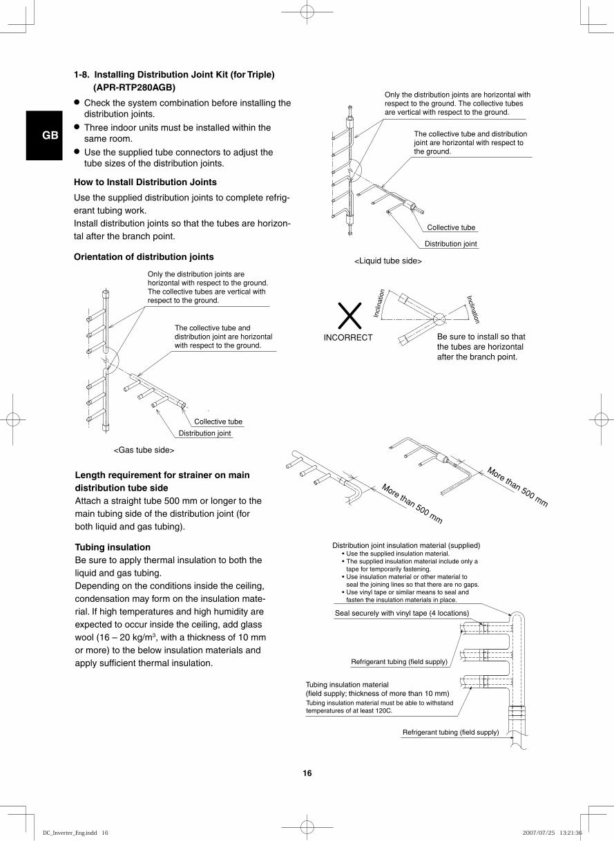
Refrigerant tubing (field supply)
Refrigerant tubing (field supply)
Seal securely with vinyl tape (4 locations)
Distribution joint insulation material (supplied)Use the supplied insulation material.The supplied insulation material include only a tape for temporarily fastening.Use insulation material or other material to seal the joining lines so that there are no gaps.Use vinyl tape or similar means to seal and fasten the insulation materials in place.
••
•
•
Tubing insulation material must be able to withstand temperatures of at least 120C.
Tubing insulation material (field supply; thickness of more than 10 mm)
Only the distribution joints are horizontal with respect to the ground. The collective tubes are vertical with respect to the ground.
The collective tube and distribution joint are horizontal with respect to the ground.
Collective tube
Distribution joint
<Liquid tube side>
1-8. Installing Distribution Joint Kit (for Triple) (APR-RTP280AGB)
● Check the system combination before installing the distribution joints.
● Three indoor units must be installed within the same room.
● Use the supplied tube connectors to adjust the tube sizes of the distribution joints.
How to Install Distribution Joints
Use the supplied distribution joints to complete refrig-erant tubing work.Install distribution joints so that the tubes are horizon-tal after the branch point.
Orientation of distribution joints
Only the distribution joints are horizontal with respect to the ground. The collective tubes are vertical with respect to the ground.
The collective tube and distribution joint are horizontal with respect to the ground.
Collective tube
Distribution joint
<Gas tube side>
Incl
inat
ion Inclination
Be sure to install so that the tubes are horizontal after the branch point.
INCORRECT
Length requirement for strainer on main distribution tube sideAttach a straight tube 500 mm or longer to the main tubing side of the distribution joint (for both liquid and gas tubing).
Tubing insulationBe sure to apply thermal insulation to both the liquid and gas tubing. Depending on the conditions inside the ceiling, condensation may form on the insulation mate-rial. If high temperatures and high humidity are expected to occur inside the ceiling, add glass wool (16 – 20 kg/m3, with a thickness of 10 mm or more) to the below insulation materials and apply sufficient thermal insulation.
More than 500 mm
More than 500 mm
DC_Inverter_Eng.indd 16DC_Inverter_Eng.indd 16 2007/07/25 13:21:362007/07/25 13:21:36
GB
FR
DE
IT
PT
GR
ES
17
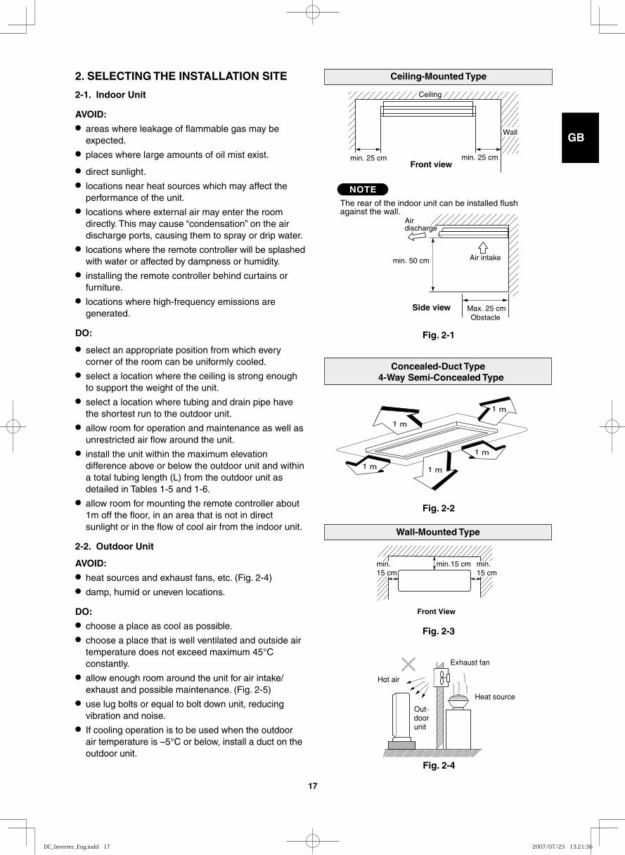
2. SELECTING THE INSTALLATION SITE
2-1. Indoor Unit
AVOID:● areas where leakage of flammable gas may be
expected.● places where large amounts of oil mist exist.
● direct sunlight.● locations near heat sources which may affect the
performance of the unit.● locations where external air may enter the room
directly. This may cause “condensation” on the air discharge ports, causing them to spray or drip water.
● locations where the remote controller will be splashed with water or affected by dampness or humidity.
● installing the remote controller behind curtains or furniture.
● locations where high-frequency emissions are generated.
DO:
● select an appropriate position from which every corner of the room can be uniformly cooled.
● select a location where the ceiling is strong enough to support the weight of the unit.
● select a location where tubing and drain pipe have the shortest run to the outdoor unit.
● allow room for operation and maintenance as well as unrestricted air flow around the unit.
● install the unit within the maximum elevation difference above or below the outdoor unit and within a total tubing length (L) from the outdoor unit as detailed in Tables 1-5 and 1-6.
● allow room for mounting the remote controller about 1m off the floor, in an area that is not in direct sunlight or in the flow of cool air from the indoor unit.
2-2. Outdoor Unit
AVOID:● heat sources and exhaust fans, etc. (Fig. 2-4)● damp, humid or uneven locations.
DO:● choose a place as cool as possible.● choose a place that is well ventilated and outside air
temperature does not exceed maximum 45°C constantly.
● allow enough room around the unit for air intake/exhaust and possible maintenance. (Fig. 2-5)
● use lug bolts or equal to bolt down unit, reducing vibration and noise.
● If cooling operation is to be used when the outdoor air temperature is –5°C or below, install a duct on the outdoor unit.
Concealed-Duct Type 4-Way Semi-Concealed Type
1 m
1 m 1 m
1 m
1 m
Wall-Mounted Type
min.15 cm
Front View
min.15 cm
min.15 cm
Ceiling-Mounted Type
Side view
min. 25 cm
The rear of the indoor unit can be installed flushagainst the wall.
min. 50 cm Air intake
Airdischarge
min. 25 cm
Ceiling
Wall
NOTE
Front view
Max. 25 cmObstacle
Fig. 2-1
Fig. 2-2
Fig. 2-3
NOTE
Fig. 2-4
Out-doorunit
Heat source
Hot air
Exhaust fan
DC_Inverter_Eng.indd 17DC_Inverter_Eng.indd 17 2007/07/25 13:21:362007/07/25 13:21:36
GB
FR
DE
IT
PT
GR
ES
18
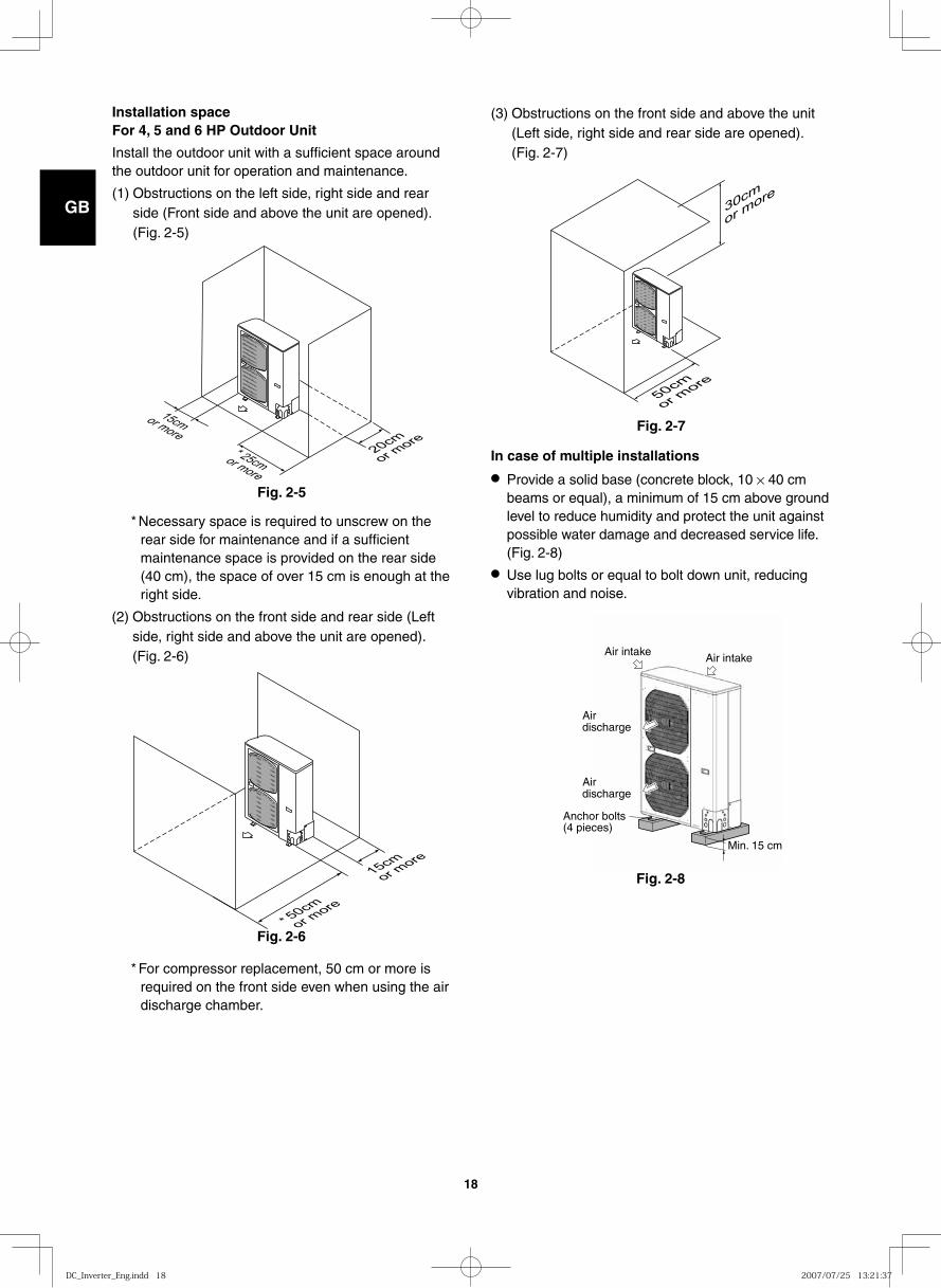
Installation spaceFor 4, 5 and 6 HP Outdoor Unit
Install the outdoor unit with a sufficient space around the outdoor unit for operation and maintenance.
(1) Obstructions on the left side, right side and rear side (Front side and above the unit are opened). (Fig. 2-5)
Air intakeAir intake
Airdischarge
Airdischarge
Anchor bolts(4 pieces)
Min. 15 cm
In case of multiple installations
● Provide a solid base (concrete block, 10 × 40 cm beams or equal), a minimum of 15 cm above ground level to reduce humidity and protect the unit against possible water damage and decreased service life. (Fig. 2-8)
● Use lug bolts or equal to bolt down unit, reducing vibration and noise.
Fig. 2-5
15cm or more
25cm or more
* 20cm
or more
Fig. 2-6
15cm
or more
50cm
or more
*
Fig. 2-8
(3) Obstructions on the front side and above the unit (Left side, right side and rear side are opened). (Fig. 2-7)
* Necessary space is required to unscrew on the rear side for maintenance and if a sufficient maintenance space is provided on the rear side (40 cm), the space of over 15 cm is enough at the right side.
(2) Obstructions on the front side and rear side (Left side, right side and above the unit are opened). (Fig. 2-6)
* For compressor replacement, 50 cm or more is required on the front side even when using the air discharge chamber.
30cm
or more
50cm
or more
Fig. 2-7
DC_Inverter_Eng.indd 18DC_Inverter_Eng.indd 18 2007/07/25 13:21:372007/07/25 13:21:37
GB
FR
DE
IT
PT
GR
ES
19
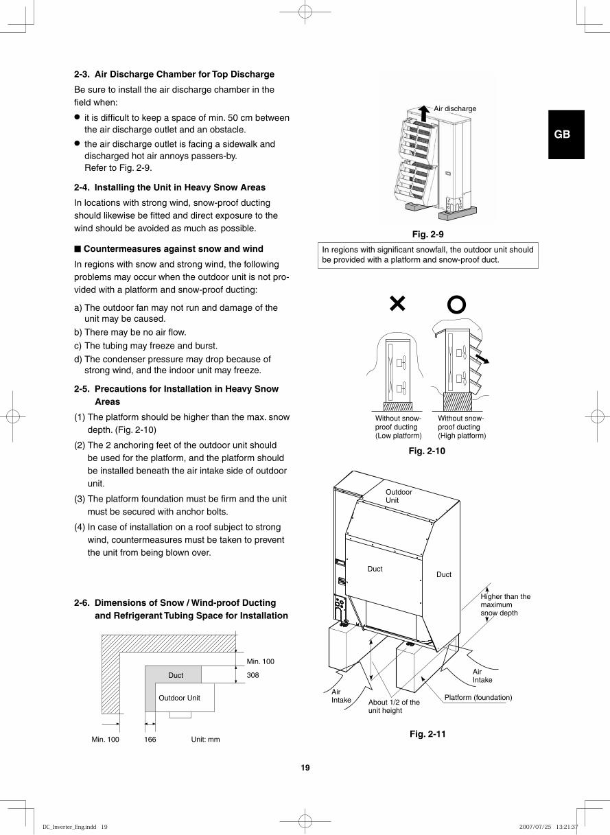
Fig. 2-9
Fig. 2-10
Fig. 2-11
2-3. Air Discharge Chamber for Top Discharge
Be sure to install the air discharge chamber in the field when:
● it is difficult to keep a space of min. 50 cm between the air discharge outlet and an obstacle.
● the air discharge outlet is facing a sidewalk and discharged hot air annoys passers-by.Refer to Fig. 2-9.
2-4. Installing the Unit in Heavy Snow Areas
In locations with strong wind, snow-proof ducting should likewise be fitted and direct exposure to the wind should be avoided as much as possible.
■ Countermeasures against snow and wind
In regions with snow and strong wind, the following problems may occur when the outdoor unit is not pro-vided with a platform and snow-proof ducting:
a) The outdoor fan may not run and damage of the unit may be caused.
b) There may be no air flow.
c) The tubing may freeze and burst.
d) The condenser pressure may drop because of strong wind, and the indoor unit may freeze.
2-5. Precautions for Installation in Heavy Snow Areas
(1) The platform should be higher than the max. snow depth. (Fig. 2-10)
(2) The 2 anchoring feet of the outdoor unit should be used for the platform, and the platform should be installed beneath the air intake side of outdoor unit.
(3) The platform foundation must be firm and the unit must be secured with anchor bolts.
(4) In case of installation on a roof subject to strong wind, countermeasures must be taken to prevent the unit from being blown over.
Air discharge
In regions with significant snowfall, the outdoor unit should be provided with a platform and snow-proof duct.
Without snow-proof ducting(Low platform)
Without snow-proof ducting(High platform)
Air Intake
Platform (foundation)
Higher than the maximum snow depth
About 1/2 of the unit height
AirIntake
Duct Duct
Outdoor Unit
Duct
Outdoor Unit
Min. 100
308
Min. 100 166 Unit: mm
2-6. Dimensions of Snow / Wind-proof Ducting and Refrigerant Tubing Space for Installation
DC_Inverter_Eng.indd 19DC_Inverter_Eng.indd 19 2007/07/25 13:21:372007/07/25 13:21:37
GB
FR
DE
IT
PT
GR
ES
20
3. HOW TO INSTALL THE INDOOR UNIT
■ 4-Way Air Discharge Semi-Concealed Type (X Type)
3-1. Preparation for Ceiling Suspension
This unit uses a drain pump. Use a carpenter’s level to check that the unit is level.
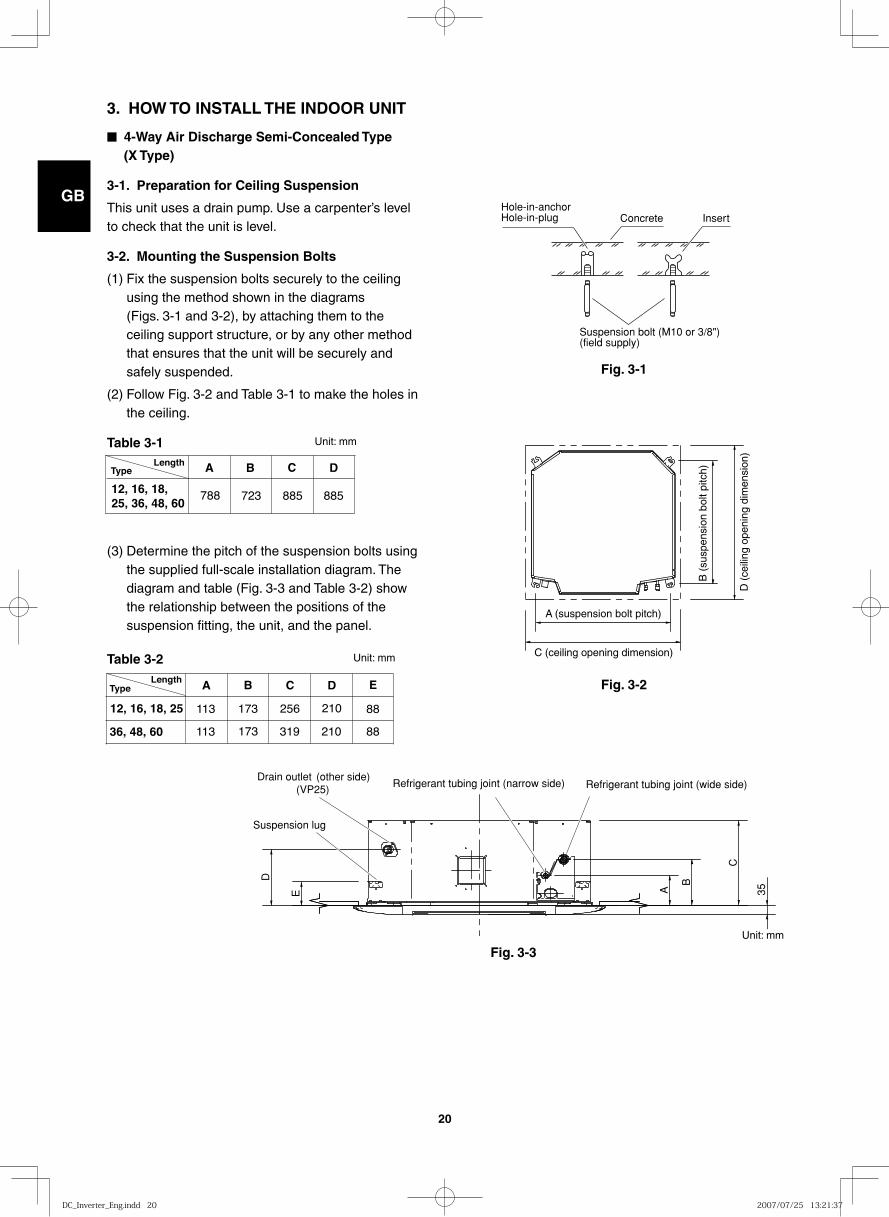
3-2. Mounting the Suspension Bolts
(1) Fix the suspension bolts securely to the ceiling using the method shown in the diagrams (Figs. 3-1 and 3-2), by attaching them to the ceiling support structure, or by any other method that ensures that the unit will be securely and safely suspended.
(2) Follow Fig. 3-2 and Table 3-1 to make the holes in the ceiling.
Table 3-1 Unit: mm
(3) Determine the pitch of the suspension bolts using the supplied full-scale installation diagram. The diagram and table (Fig. 3-3 and Table 3-2) show the relationship between the positions of the suspension fitting, the unit, and the panel.
Table 3-2 Unit: mm
Fig. 3-1
Fig. 3-2
Fig. 3-3
Hole-in-anchorHole-in-plug Concrete Insert
Suspension bolt (M10 or 3/8")(field supply)
Type A B C D
788 723 88588512, 16, 18, 25, 36, 48, 60
Length
A B C D
113 173
173
210
210
256
36, 48, 60
12, 16, 18, 25
E
88
88319113
TypeLength
D (
ceili
ng o
peni
ng d
imen
sion
)
C (ceiling opening dimension)
A (suspension bolt pitch)
B (
susp
ensi
on b
olt p
itch)
E A
B
C
D
35
Suspension lug
Refrigerant tubing joint (narrow side) Refrigerant tubing joint (wide side)(VP25)Drain outlet (other side)
Unit: mm
DC_Inverter_Eng.indd 20DC_Inverter_Eng.indd 20 2007/07/25 13:21:372007/07/25 13:21:37
GB
FR
DE
IT
PT
GR
ES
21
Fig. 3-4
Fig. 3-5
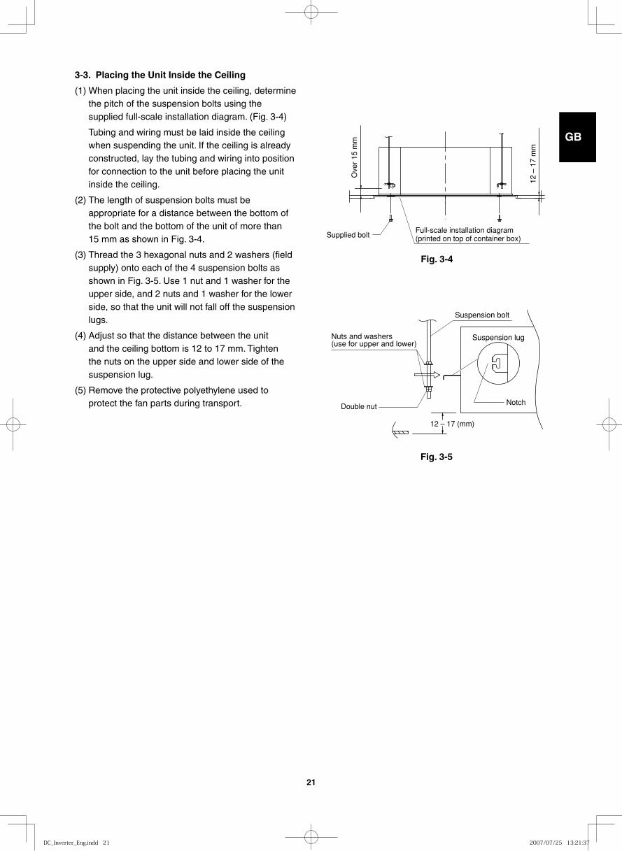
3-3. Placing the Unit Inside the Ceiling
(1) When placing the unit inside the ceiling, determine the pitch of the suspension bolts using the supplied full-scale installation diagram. (Fig. 3-4)
Tubing and wiring must be laid inside the ceiling when suspending the unit. If the ceiling is already constructed, lay the tubing and wiring into position for connection to the unit before placing the unit inside the ceiling.
(2) The length of suspension bolts must be appropriate for a distance between the bottom of the bolt and the bottom of the unit of more than 15 mm as shown in Fig. 3-4.
(3) Thread the 3 hexagonal nuts and 2 washers (field supply) onto each of the 4 suspension bolts as shown in Fig. 3-5. Use 1 nut and 1 washer for the upper side, and 2 nuts and 1 washer for the lower side, so that the unit will not fall off the suspension lugs.
(4) Adjust so that the distance between the unit and the ceiling bottom is 12 to 17 mm. Tighten the nuts on the upper side and lower side of the suspension lug.
(5) Remove the protective polyethylene used to protect the fan parts during transport.
Full-scale installation diagram (printed on top of container box)Supplied bolt
Ove
r 15
mm
12 –
17
mm
12 – 17 (mm)
Suspension bolt
Suspension lugNuts and washers (use for upper and lower)
NotchDouble nut
DC_Inverter_Eng.indd 21DC_Inverter_Eng.indd 21 2007/07/25 13:21:372007/07/25 13:21:37
GB
FR
DE
IT
PT
GR
ES
22
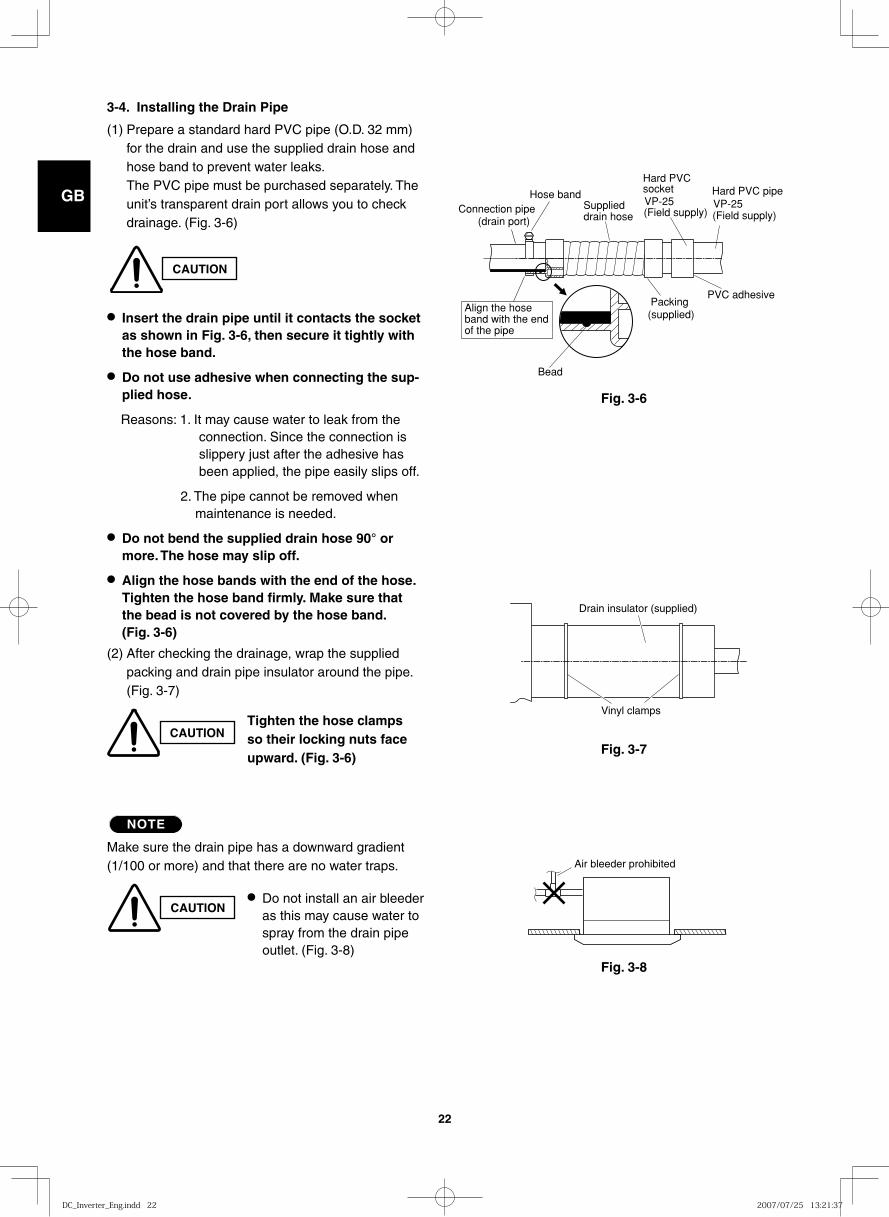
3-4. Installing the Drain Pipe
(1) Prepare a standard hard PVC pipe (O.D. 32 mm) for the drain and use the supplied drain hose and hose band to prevent water leaks.The PVC pipe must be purchased separately. The unit’s transparent drain port allows you to check drainage. (Fig. 3-6)
● Insert the drain pipe until it contacts the socket as shown in Fig. 3-6, then secure it tightly with the hose band.
● Do not use adhesive when connecting the sup-plied hose.
Reasons: 1. It may cause water to leak from the connection. Since the connection is slippery just after the adhesive has been applied, the pipe easily slips off.
2. The pipe cannot be removed when maintenance is needed.
● Do not bend the supplied drain hose 90° or more. The hose may slip off.
● Align the hose bands with the end of the hose. Tighten the hose band firmly. Make sure that the bead is not covered by the hose band. (Fig. 3-6)
(2) After checking the drainage, wrap the supplied packing and drain pipe insulator around the pipe. (Fig. 3-7)
NOTE
Make sure the drain pipe has a downward gradient (1/100 or more) and that there are no water traps.
CAUTION
CAUTIONTighten the hose clamps so their locking nuts face upward. (Fig. 3-6)
CAUTION● Do not install an air bleeder
as this may cause water to spray from the drain pipe outlet. (Fig. 3-8)
Fig. 3-6
Fig. 3-7
Fig. 3-8
Bead
Hose bandSupplieddrain hose
Connection pipe(drain port)
Align the hoseband with the endof the pipe
(Field supply) (Field supply)
Packing (supplied)
VP-25VP-25
Hard PVC socket Hard PVC pipe
PVC adhesive
Vinyl clamps
Drain insulator (supplied)
Air bleeder prohibited
DC_Inverter_Eng.indd 22DC_Inverter_Eng.indd 22 2007/07/25 13:21:372007/07/25 13:21:37
GB
FR
DE
IT
PT
GR
ES
23
CAUTION
Fig. 3-9
30 cm or less (as short as possible)
64 cm or less
Fig. 3-10
Upward gradient prohibited
Fig. 3-11
Fig. 3-12
Supportpieces
Water (Approx. 1,200 cc)
Over 100 mm
Drain pan outlet
Drainage check
Plastic container for water intake
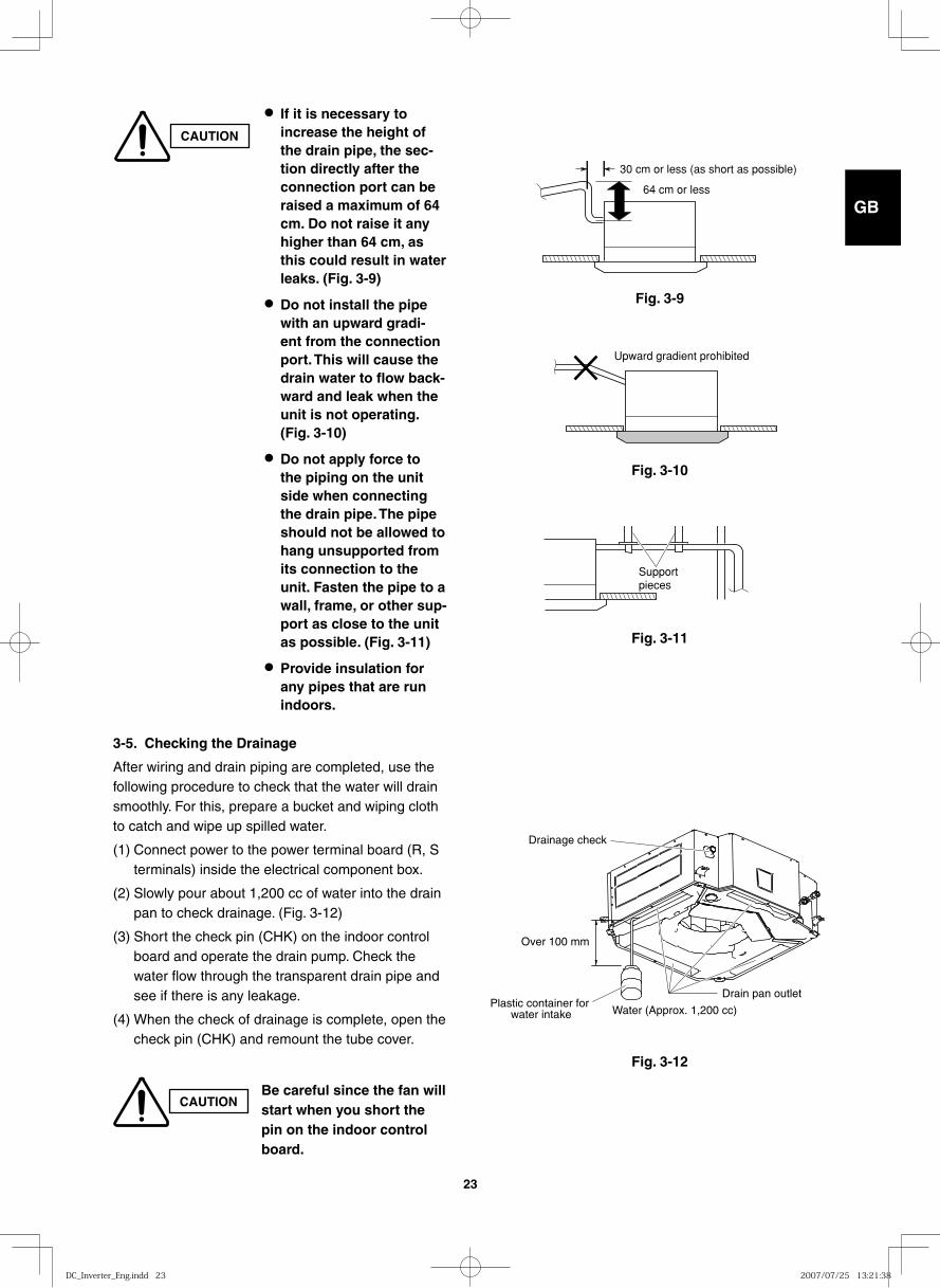
● If it is necessary to increase the height of the drain pipe, the sec-tion directly after the connection port can be raised a maximum of 64 cm. Do not raise it any higher than 64 cm, as this could result in water leaks. (Fig. 3-9)
● Do not install the pipe with an upward gradi-ent from the connection port. This will cause the drain water to flow back-ward and leak when the unit is not operating. (Fig. 3-10)
● Do not apply force to the piping on the unit side when connecting the drain pipe. The pipe should not be allowed to hang unsupported from its connection to the unit. Fasten the pipe to a wall, frame, or other sup-port as close to the unit as possible. (Fig. 3-11)
● Provide insulation for any pipes that are run indoors.
3-5. Checking the Drainage
After wiring and drain piping are completed, use the following procedure to check that the water will drain smoothly. For this, prepare a bucket and wiping cloth to catch and wipe up spilled water.
(1) Connect power to the power terminal board (R, S terminals) inside the electrical component box.
(2) Slowly pour about 1,200 cc of water into the drain pan to check drainage. (Fig. 3-12)
(3) Short the check pin (CHK) on the indoor control board and operate the drain pump. Check the water flow through the transparent drain pipe and see if there is any leakage.
(4) When the check of drainage is complete, open the check pin (CHK) and remount the tube cover.
CAUTIONBe careful since the fan will start when you short the pin on the indoor control board.
DC_Inverter_Eng.indd 23DC_Inverter_Eng.indd 23 2007/07/25 13:21:382007/07/25 13:21:38
GB
FR
DE
IT
PT
GR
ES
24
■ Wall-Mounted Type (K Type)
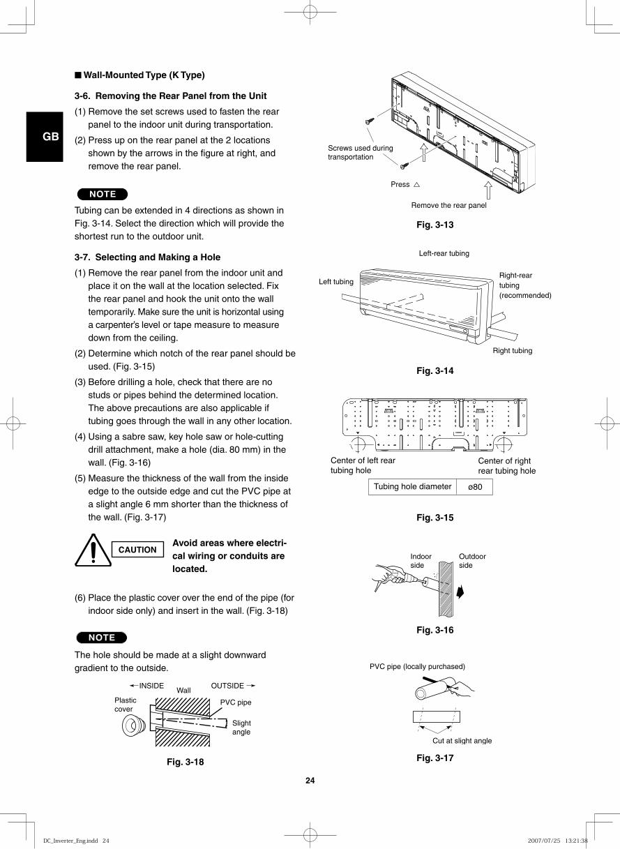
3-6. Removing the Rear Panel from the Unit
(1) Remove the set screws used to fasten the rear panel to the indoor unit during transportation.
(2) Press up on the rear panel at the 2 locations shown by the arrows in the figure at right, and remove the rear panel.
NOTE
Tubing can be extended in 4 directions as shown in Fig. 3-14. Select the direction which will provide the shortest run to the outdoor unit.
3-7. Selecting and Making a Hole
(1) Remove the rear panel from the indoor unit and place it on the wall at the location selected. Fix the rear panel and hook the unit onto the wall temporarily. Make sure the unit is horizontal using a carpenter’s level or tape measure to measure down from the ceiling.
(2) Determine which notch of the rear panel should be used. (Fig. 3-15)
(3) Before drilling a hole, check that there are no studs or pipes behind the determined location. The above precautions are also applicable if tubing goes through the wall in any other location.
(4) Using a sabre saw, key hole saw or hole-cutting drill attachment, make a hole (dia. 80 mm) in the wall. (Fig. 3-16)
(5) Measure the thickness of the wall from the inside edge to the outside edge and cut the PVC pipe at a slight angle 6 mm shorter than the thickness of the wall. (Fig. 3-17)
(6) Place the plastic cover over the end of the pipe (for indoor side only) and insert in the wall. (Fig. 3-18)
NOTE
The hole should be made at a slight downward gradient to the outside.
Fig. 3-13
Fig. 3-14
Fig. 3-15
Fig. 3-16
Fig. 3-17Fig. 3-18
CAUTIONAvoid areas where electri-cal wiring or conduits are located.
Plastic cover
INSIDEWall
Slightangle
PVC pipe
OUTSIDE
Cut at slight angle
PVC pipe (locally purchased)
Indoorside
Outdoorside
Center of left rear tubing hole
Center of right rear tubing hole
Tubing hole diameter ø80
Left tubing Right-reartubing(recommended)
Right tubing
Left-rear tubing
Remove the rear panel
Press
Screws used during transportation
DC_Inverter_Eng.indd 24DC_Inverter_Eng.indd 24 2007/07/25 13:21:382007/07/25 13:21:38
GB
FR
DE
IT
PT
GR
ES
25
Fig. 3-19
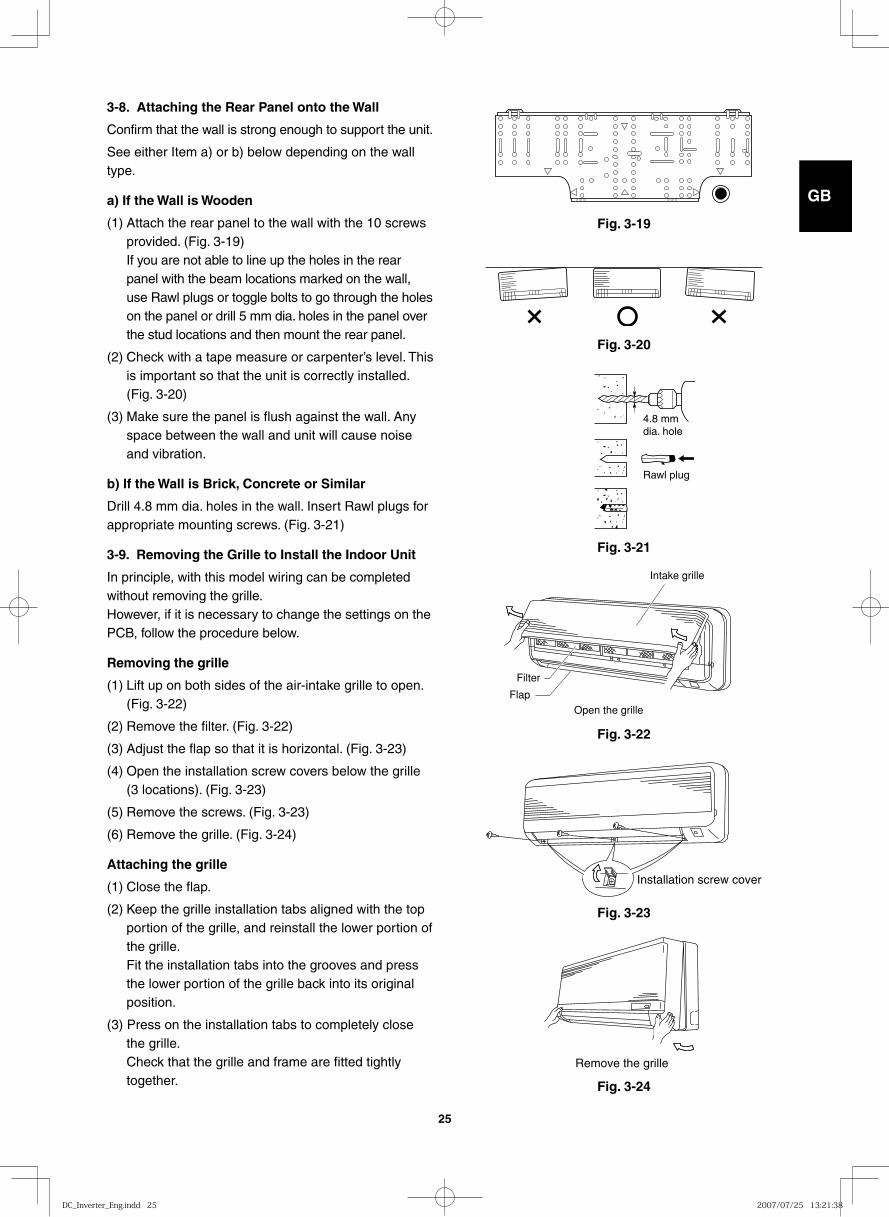
3-8. Attaching the Rear Panel onto the Wall
Confirm that the wall is strong enough to support the unit.
See either Item a) or b) below depending on the wall type.
a) If the Wall is Wooden
(1) Attach the rear panel to the wall with the 10 screws provided. (Fig. 3-19)If you are not able to line up the holes in the rear panel with the beam locations marked on the wall, use Rawl plugs or toggle bolts to go through the holes on the panel or drill 5 mm dia. holes in the panel over the stud locations and then mount the rear panel.
(2) Check with a tape measure or carpenter’s level. This is important so that the unit is correctly installed. (Fig. 3-20)
(3) Make sure the panel is flush against the wall. Any space between the wall and unit will cause noise and vibration.
b) If the Wall is Brick, Concrete or Similar
Drill 4.8 mm dia. holes in the wall. Insert Rawl plugs for appropriate mounting screws. (Fig. 3-21)
3-9. Removing the Grille to Install the Indoor Unit
In principle, with this model wiring can be completed without removing the grille. However, if it is necessary to change the settings on the PCB, follow the procedure below.
Removing the grille
(1) Lift up on both sides of the air-intake grille to open. (Fig. 3-22)
(2) Remove the filter. (Fig. 3-22)
(3) Adjust the flap so that it is horizontal. (Fig. 3-23)
(4) Open the installation screw covers below the grille (3 locations). (Fig. 3-23)
(5) Remove the screws. (Fig. 3-23)
(6) Remove the grille. (Fig. 3-24)
Attaching the grille
(1) Close the flap.
(2) Keep the grille installation tabs aligned with the top portion of the grille, and reinstall the lower portion of the grille. Fit the installation tabs into the grooves and press the lower portion of the grille back into its original position.
(3) Press on the installation tabs to completely close the grille. Check that the grille and frame are fitted tightly together.
Fig. 3-20
Fig. 3-21
Fig. 3-22
Fig. 3-23
Fig. 3-24
4.8 mmdia. hole
Rawl plug
Intake grille
Filter
Flap
Open the grille
Installation screw cover
Remove the grille
DC_Inverter_Eng.indd 25DC_Inverter_Eng.indd 25 2007/07/25 13:21:382007/07/25 13:21:38
GB
FR
DE
IT
PT
GR
ES
26
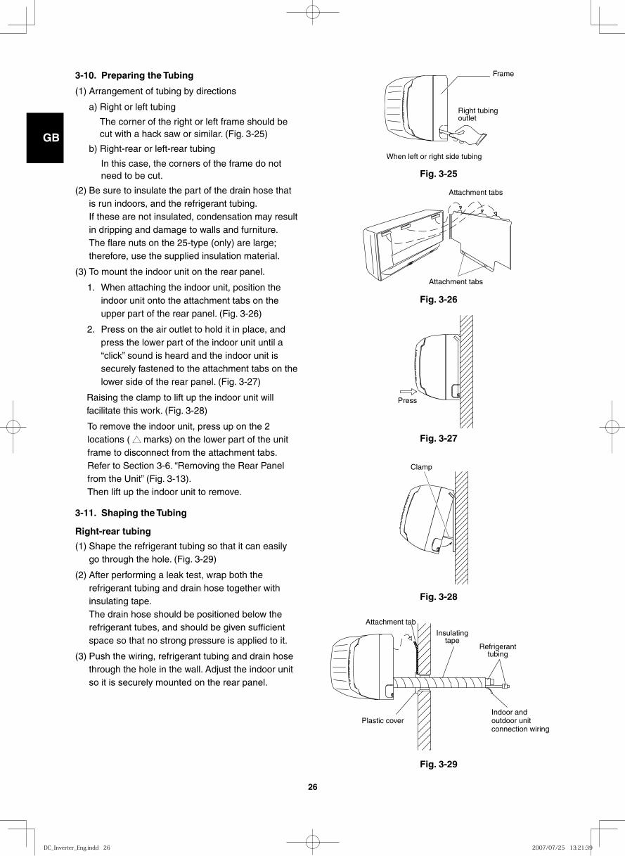
3-10. Preparing the Tubing
(1) Arrangement of tubing by directions
a) Right or left tubing
The corner of the right or left frame should be cut with a hack saw or similar. (Fig. 3-25)
b) Right-rear or left-rear tubing
In this case, the corners of the frame do not need to be cut.
(2) Be sure to insulate the part of the drain hose that is run indoors, and the refrigerant tubing. If these are not insulated, condensation may result in dripping and damage to walls and furniture. The flare nuts on the 25-type (only) are large; therefore, use the supplied insulation material.
(3) To mount the indoor unit on the rear panel.
1. When attaching the indoor unit, position the indoor unit onto the attachment tabs on the upper part of the rear panel. (Fig. 3-26)
2. Press on the air outlet to hold it in place, and press the lower part of the indoor unit until a “click” sound is heard and the indoor unit is securely fastened to the attachment tabs on the lower side of the rear panel. (Fig. 3-27)
Raising the clamp to lift up the indoor unit will facilitate this work. (Fig. 3-28)
To remove the indoor unit, press up on the 2 locations ( ▲▲ marks) on the lower part of the unit frame to disconnect from the attachment tabs. Refer to Section 3-6. “Removing the Rear Panel from the Unit” (Fig. 3-13).Then lift up the indoor unit to remove.
3-11. Shaping the Tubing
Right-rear tubing
(1) Shape the refrigerant tubing so that it can easily go through the hole. (Fig. 3-29)
(2) After performing a leak test, wrap both the refrigerant tubing and drain hose together with insulating tape. The drain hose should be positioned below the refrigerant tubes, and should be given sufficient space so that no strong pressure is applied to it.
(3) Push the wiring, refrigerant tubing and drain hose through the hole in the wall. Adjust the indoor unit so it is securely mounted on the rear panel.
Fig. 3-25
Frame
Right tubingoutlet
When left or right side tubing
Fig. 3-26
Attachment tabs
Attachment tabs
Fig. 3-27
Press
Fig. 3-28
Clamp
Fig. 3-29
Insulatingtape
Refrigeranttubing
Attachment tab
Plastic coverIndoor and outdoor unit connection wiring
DC_Inverter_Eng.indd 26DC_Inverter_Eng.indd 26 2007/07/25 13:21:392007/07/25 13:21:39
GB
FR
DE
IT
PT
GR
ES
27
Fig. 3-32
Fig. 3-30
Insulation
Fig. 3-31
Insulating tape Rear panel
Inter-unit wiring
Refrigerant tubing
Drain hose
Indoor unit
Slant
Refrigeranttubing
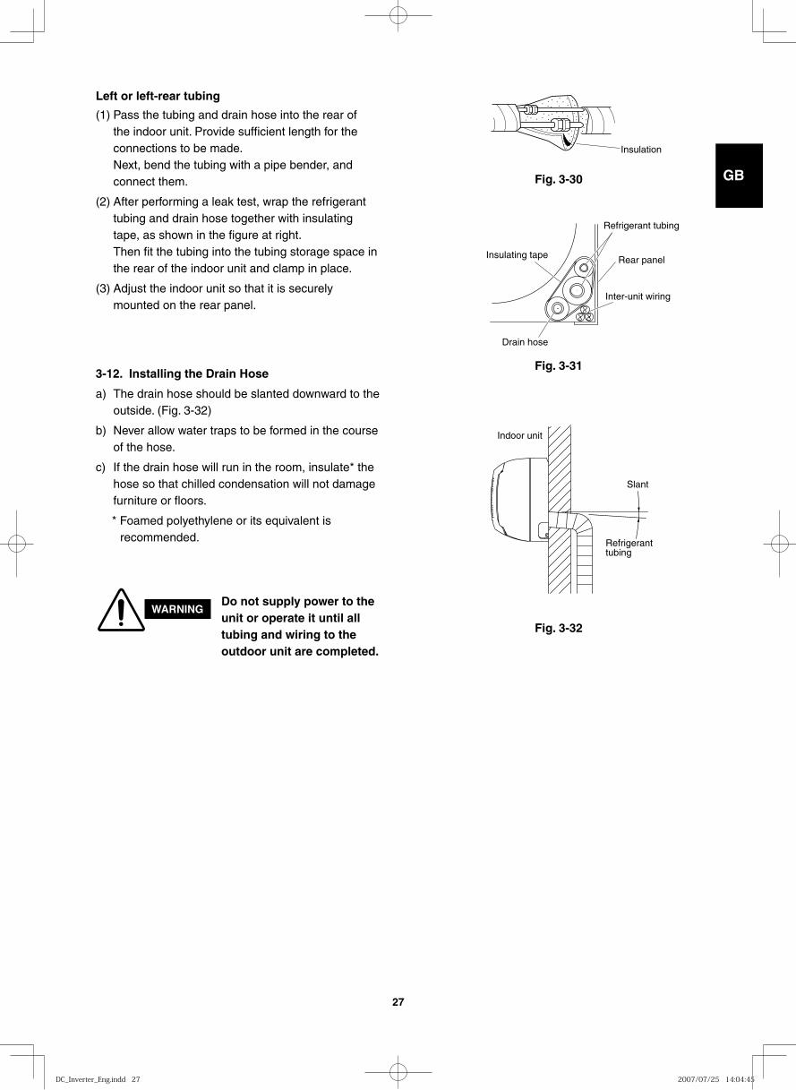
3-12. Installing the Drain Hose
a) The drain hose should be slanted downward to the outside. (Fig. 3-32)
b) Never allow water traps to be formed in the course of the hose.
c) If the drain hose will run in the room, insulate* the hose so that chilled condensation will not damage furniture or floors.
* Foamed polyethylene or its equivalent is recommended.
WARNINGDo not supply power to the unit or operate it until all tubing and wiring to the outdoor unit are completed.
Left or left-rear tubing
(1) Pass the tubing and drain hose into the rear of the indoor unit. Provide sufficient length for the connections to be made.Next, bend the tubing with a pipe bender, and connect them.
(2) After performing a leak test, wrap the refrigerant tubing and drain hose together with insulating tape, as shown in the figure at right. Then fit the tubing into the tubing storage space in the rear of the indoor unit and clamp in place.
(3) Adjust the indoor unit so that it is securely mounted on the rear panel.
DC_Inverter_Eng.indd 27DC_Inverter_Eng.indd 27 2007/07/25 14:04:452007/07/25 14:04:45
GB
FR
DE
IT
PT
GR
ES
28
■ Ceiling-Mounted Type (T Type)
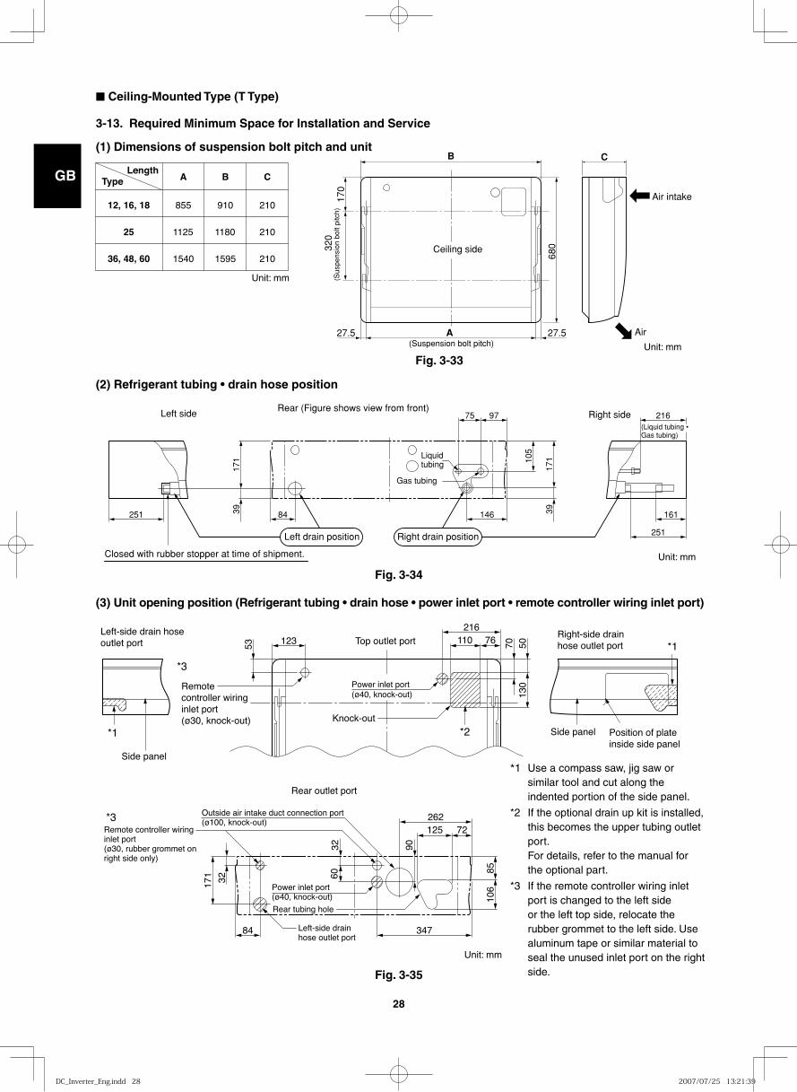
3-13. Required Minimum Space for Installation and Service
(1) Dimensions of suspension bolt pitch and unit
12, 16, 18
25
36, 48, 60
855
1125
1540
910
1180
1595
210
210
210
A B CLength
Type
B C
A17
032
0
680
27.5 27.5
Ceiling side
(Suspension bolt pitch)(S
uspe
nsio
n bo
lt pi
tch)
Air intake
Air
(2) Refrigerant tubing • drain hose position
(3) Unit opening position (Refrigerant tubing • drain hose • power inlet port • remote controller wiring inlet port)
251 84 146 161
75 97 216
39 39
171 10
5
171
251
Gas tubing
Liquid tubing
Right sideLeft sideRear (Figure shows view from front)
Closed with rubber stopper at time of shipment.
Left drain position Right drain position
(Liquid tubing • Gas tubing)
53 70123 110 76216
5013
0
Left-side drain hose outlet port
Right-side drain hose outlet port Top outlet port
Remote controller wiring inlet port(ø30, knock-out)
Power inlet port(ø40, knock-out)
Power inlet port(ø40, knock-out)
Knock-out
Side panel
Position of plate inside side panel
Side panel
Left-side drain hose outlet port
Rear tubing hole
84
32
3260
171
347
125 72
8510
6
90
262Remote controller wiring inlet port(ø30, rubber grommet on right side only)
Outside air intake duct connection port(ø100, knock-out)
Rear outlet port
*3
*1
*1
*2
*3
Fig. 3-33
Unit: mm
Unit: mm
Unit: mm
Unit: mm
Fig. 3-34
Fig. 3-35
*1 Use a compass saw, jig saw or similar tool and cut along the indented portion of the side panel.
*2 If the optional drain up kit is installed, this becomes the upper tubing outlet port. For details, refer to the manual for the optional part.
*3 If the remote controller wiring inlet port is changed to the left side or the left top side, relocate the rubber grommet to the left side. Use aluminum tape or similar material to seal the unused inlet port on the right side.
DC_Inverter_Eng.indd 28DC_Inverter_Eng.indd 28 2007/07/25 13:21:392007/07/25 13:21:39
GB
FR
DE
IT
PT
GR
ES
29
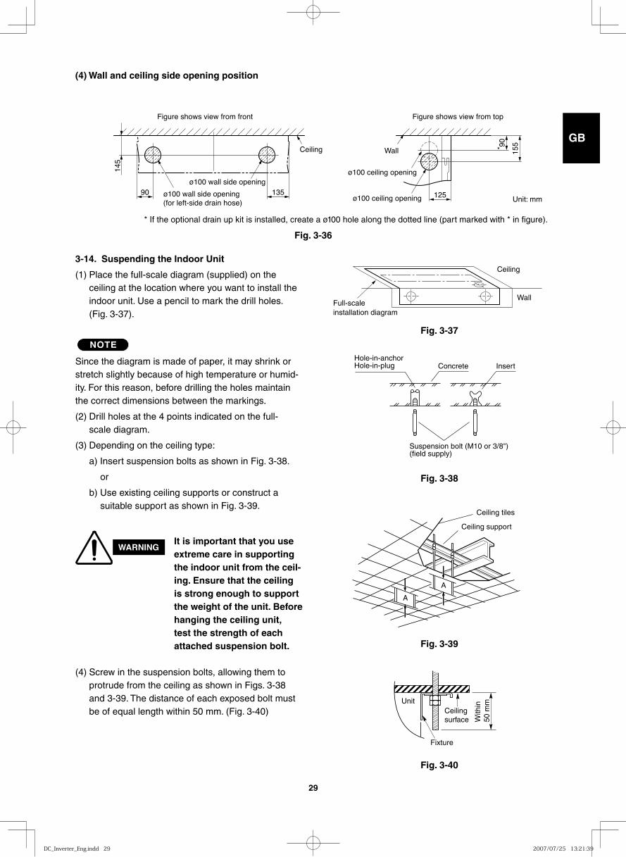
(4) Wall and ceiling side opening position
90
145
135 125
15590
*
Figure shows view from front Figure shows view from top
ø100 wall side opening (for left-side drain hose)
ø100 wall side openingø100 ceiling opening
ø100 ceiling opening
WallCeiling
Full-scale installation diagram
Wall
Ceiling
Fig. 3-37
Fig. 3-36
Fig. 3-38
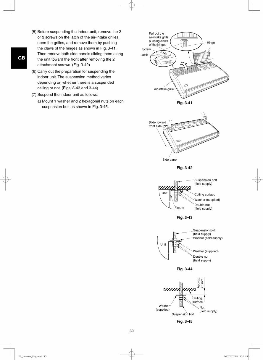
3-14. Suspending the Indoor Unit
(1) Place the full-scale diagram (supplied) on the ceiling at the location where you want to install the indoor unit. Use a pencil to mark the drill holes. (Fig. 3-37).
NOTE
Since the diagram is made of paper, it may shrink or stretch slightly because of high temperature or humid-ity. For this reason, before drilling the holes maintain the correct dimensions between the markings.
(2) Drill holes at the 4 points indicated on the full-scale diagram.
(3) Depending on the ceiling type:
a) Insert suspension bolts as shown in Fig. 3-38.
or
b) Use existing ceiling supports or construct a suitable support as shown in Fig. 3-39.
WARNINGIt is important that you use extreme care in supporting the indoor unit from the ceil-ing. Ensure that the ceiling is strong enough to support the weight of the unit. Before hanging the ceiling unit, test the strength of each attached suspension bolt.
(4) Screw in the suspension bolts, allowing them to protrude from the ceiling as shown in Figs. 3-38 and 3-39. The distance of each exposed bolt must be of equal length within 50 mm. (Fig. 3-40)
Hole-in-anchorHole-in-plug Concrete Insert
Suspension bolt (M10 or 3/8")(field supply)
Fig. 3-39
Fig. 3-40
Ceiling tiles
Ceiling support
A
A
UnitCeilingsurface
Fixture
With
in50
mm
* If the optional drain up kit is installed, create a ø100 hole along the dotted line (part marked with * in figure).
Unit: mm
DC_Inverter_Eng.indd 29DC_Inverter_Eng.indd 29 2007/07/25 13:21:392007/07/25 13:21:39
GB
FR
DE
IT
PT
GR
ES
30
Fig. 3-41Slide
Hinge
Air-intake grille
Pull out theair-intake grillepushing clawsof the hinges
Screw
Latch
Fig. 3-42
Slide towardfront side
Side panel
Fig. 3-43
Unit
Suspension bolt(field supply)
Ceiling surface
Washer (supplied)
Double nut(field supply)Fixture
Fig. 3-44
Unit
Suspension bolt(field supply)
Washer (supplied)
Washer (field supply)
Double nut(field supply)
Fig. 3-45
Ceilingsurface
App
rox.
25
mm
Suspension bolt
Washer(supplied)
Nut(field supply)
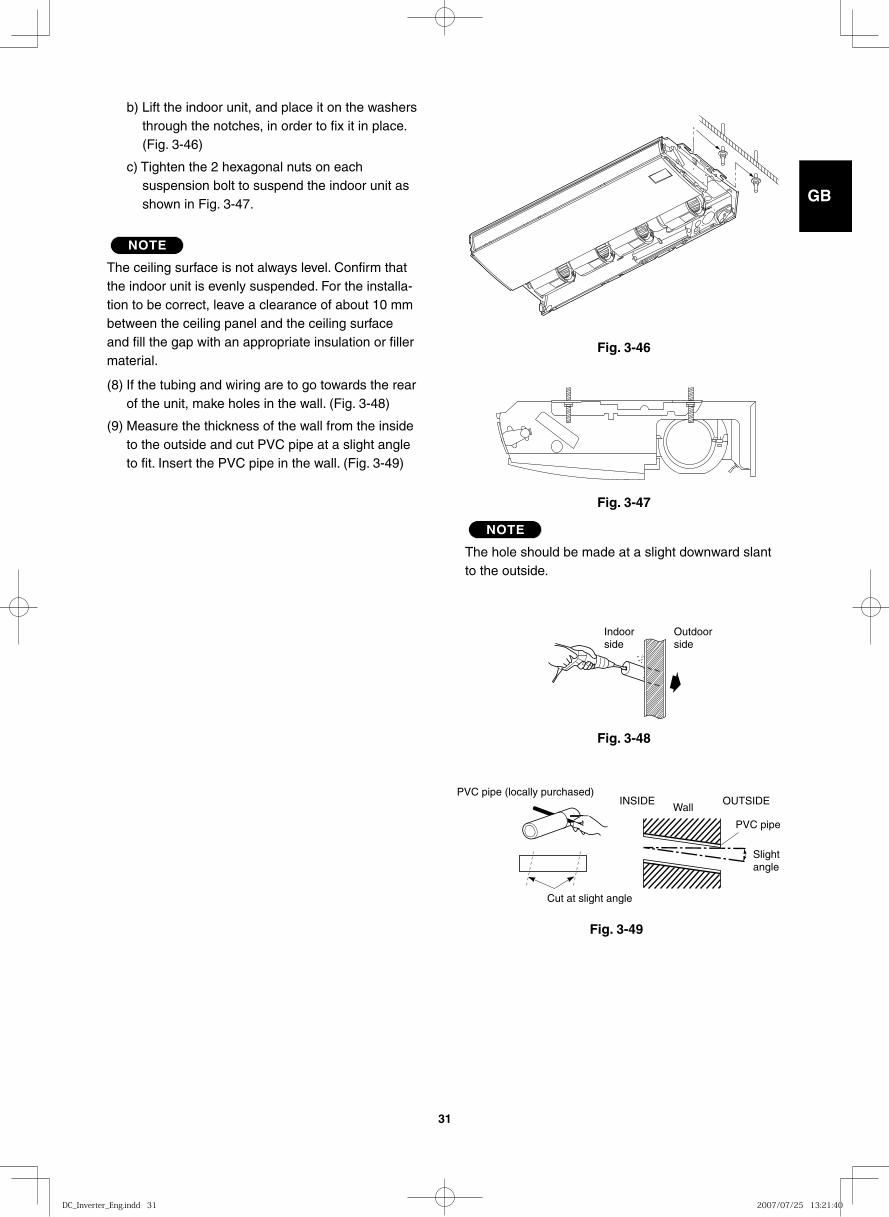
(5) Before suspending the indoor unit, remove the 2 or 3 screws on the latch of the air-intake grilles, open the grilles, and remove them by pushing the claws of the hinges as shown in Fig. 3-41. Then remove both side panels sliding them along the unit toward the front after removing the 2 attachment screws. (Fig. 3-42)
(6) Carry out the preparation for suspending the indoor unit. The suspension method varies depending on whether there is a suspended ceiling or not. (Figs. 3-43 and 3-44)
(7) Suspend the indoor unit as follows:
a) Mount 1 washer and 2 hexagonal nuts on each suspension bolt as shown in Fig. 3-45.
DC_Inverter_Eng.indd 30DC_Inverter_Eng.indd 30 2007/07/25 13:21:402007/07/25 13:21:40
GB
FR
DE
IT
PT
GR
ES
31
Fig. 3-46
Fig. 3-47
Fig. 3-48
Indoorside
Outdoorside
Fig. 3-49
Cut at slight angle
PVC pipe (locally purchased)INSIDE
Wall
Slightangle
PVC pipe
OUTSIDE
b) Lift the indoor unit, and place it on the washers through the notches, in order to fix it in place. (Fig. 3-46)
c) Tighten the 2 hexagonal nuts on each suspension bolt to suspend the indoor unit as shown in Fig. 3-47.
NOTE
The ceiling surface is not always level. Confirm that the indoor unit is evenly suspended. For the installa-tion to be correct, leave a clearance of about 10 mm between the ceiling panel and the ceiling surface and fill the gap with an appropriate insulation or filler material.
(8) If the tubing and wiring are to go towards the rear of the unit, make holes in the wall. (Fig. 3-48)
(9) Measure the thickness of the wall from the inside to the outside and cut PVC pipe at a slight angle to fit. Insert the PVC pipe in the wall. (Fig. 3-49)
NOTE
The hole should be made at a slight downward slant to the outside.
DC_Inverter_Eng.indd 31DC_Inverter_Eng.indd 31 2007/07/25 13:21:402007/07/25 13:21:40
GB
FR
DE
IT
PT
GR
ES
32
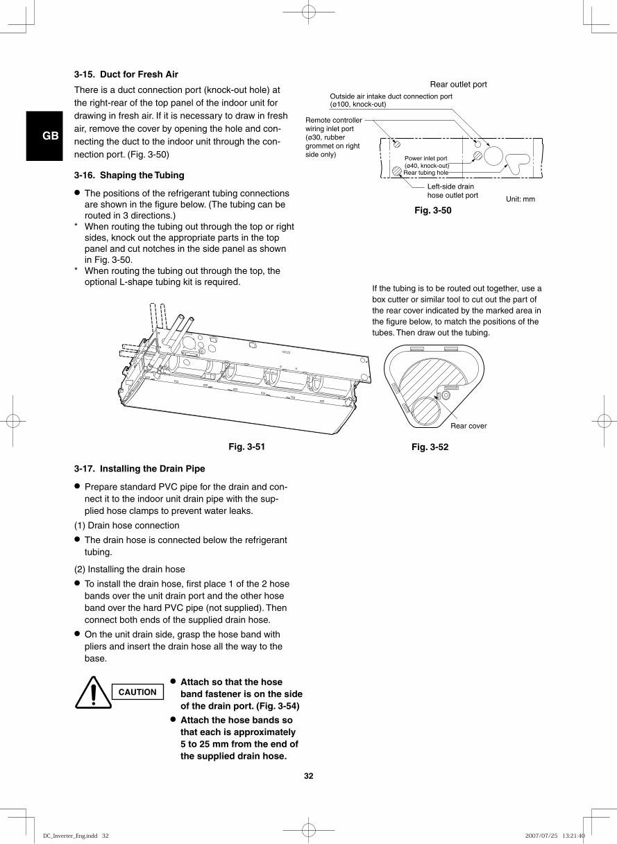
3-15. Duct for Fresh Air
There is a duct connection port (knock-out hole) at the right-rear of the top panel of the indoor unit for drawing in fresh air. If it is necessary to draw in fresh air, remove the cover by opening the hole and con-necting the duct to the indoor unit through the con-nection port. (Fig. 3-50)
3-16. Shaping the Tubing
● The positions of the refrigerant tubing connections are shown in the figure below. (The tubing can be routed in 3 directions.)
* When routing the tubing out through the top or right sides, knock out the appropriate parts in the top panel and cut notches in the side panel as shown in Fig. 3-50.
* When routing the tubing out through the top, the optional L-shape tubing kit is required.
3-17. Installing the Drain Pipe
● Prepare standard PVC pipe for the drain and con-nect it to the indoor unit drain pipe with the sup-plied hose clamps to prevent water leaks.
(1) Drain hose connection● The drain hose is connected below the refrigerant
tubing.
(2) Installing the drain hose● To install the drain hose, first place 1 of the 2 hose
bands over the unit drain port and the other hose band over the hard PVC pipe (not supplied). Then connect both ends of the supplied drain hose.
● On the unit drain side, grasp the hose band with pliers and insert the drain hose all the way to the base.
Power inlet port(ø40, knock-out)
Left-side drain hose outlet port
Rear tubing hole
Remote controller wiring inlet port(ø30, rubber grommet on right side only)
Outside air intake duct connection port(ø100, knock-out)
Rear outlet port
Rear cover
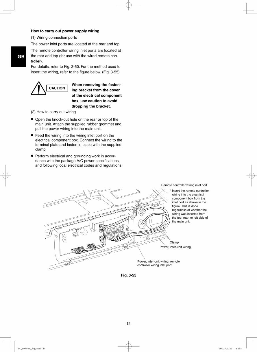
CAUTION● Attach so that the hose
band fastener is on the side of the drain port. (Fig. 3-54)
● Attach the hose bands so that each is approximately 5 to 25 mm from the end of the supplied drain hose.
If the tubing is to be routed out together, use a box cutter or similar tool to cut out the part of the rear cover indicated by the marked area in the figure below, to match the positions of the tubes. Then draw out the tubing.
Fig. 3-51 Fig. 3-52
Unit: mm
Fig. 3-50
DC_Inverter_Eng.indd 32DC_Inverter_Eng.indd 32 2007/07/25 13:21:402007/07/25 13:21:40
GB
FR
DE
IT
PT
GR
ES
33
14025 25
55
Position to fasten hose bands
Drain hose(supplied)
Hose band (2 bands, supplied)
Unit drain pan
Unit drain port Drain hose insulation (supplied)
Twist tie (4 ties, supplied)
Hard PVC pipe (equivalent to VP-20)(Field supply)
Fig. 3-54
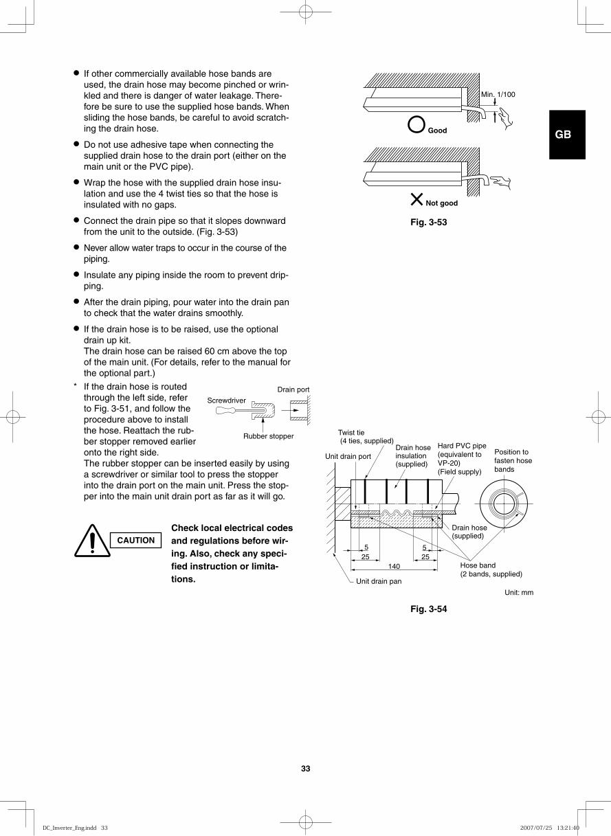
Good
Min. 1/100
Not good
Fig. 3-53
● If other commercially available hose bands are used, the drain hose may become pinched or wrin-kled and there is danger of water leakage. There-fore be sure to use the supplied hose bands. When sliding the hose bands, be careful to avoid scratch-ing the drain hose.
● Do not use adhesive tape when connecting the supplied drain hose to the drain port (either on the main unit or the PVC pipe).
● Wrap the hose with the supplied drain hose insu-lation and use the 4 twist ties so that the hose is insulated with no gaps.
● Connect the drain pipe so that it slopes downward from the unit to the outside. (Fig. 3-53)
● Never allow water traps to occur in the course of the piping.
● Insulate any piping inside the room to prevent drip-ping.
● After the drain piping, pour water into the drain pan to check that the water drains smoothly.
● If the drain hose is to be raised, use the optional drain up kit. The drain hose can be raised 60 cm above the top of the main unit. (For details, refer to the manual for the optional part.)
* If the drain hose is routed through the left side, refer to Fig. 3-51, and follow the procedure above to install the hose. Reattach the rub-ber stopper removed earlier onto the right side. The rubber stopper can be inserted easily by using a screwdriver or similar tool to press the stopper into the drain port on the main unit. Press the stop-per into the main unit drain port as far as it will go.
Screwdriver
Rubber stopper
Drain port
CAUTIONCheck local electrical codes and regulations before wir-ing. Also, check any speci-fied instruction or limita-tions.
Unit: mm
DC_Inverter_Eng.indd 33DC_Inverter_Eng.indd 33 2007/07/25 13:21:402007/07/25 13:21:40
GB
FR
DE
IT
PT
GR
ES
34
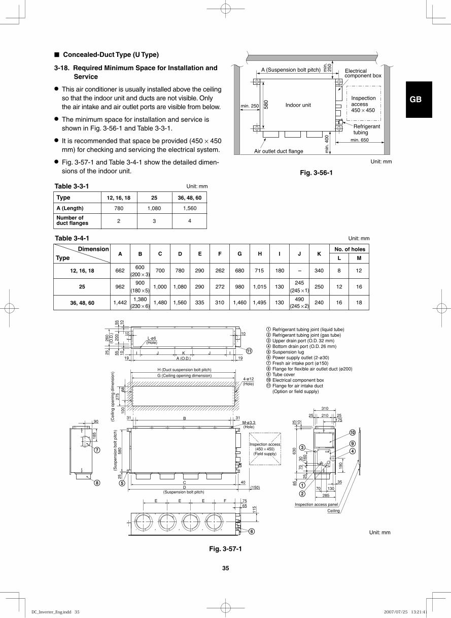
* Insert the remote controller wiring into the electrical component box from the inlet port as shown in the figure. This is done regardless of whether the wiring was inserted from the top, rear, or left side of the main unit.
Remote controller wiring inlet port
Power, inter-unit wiring
Power, inter-unit wiring, remote controller wiring inlet port
Clamp
How to carry out power supply wiring
(1) Wiring connection ports
The power inlet ports are located at the rear and top.
The remote controller wiring inlet ports are located at the rear and top (for use with the wired remote con-troller). For details, refer to Fig. 3-50. For the method used to insert the wiring, refer to the figure below. (Fig. 3-55)
(2) How to carry out wiring
● Open the knock-out hole on the rear or top of the main unit. Attach the supplied rubber grommet and pull the power wiring into the main unit.
● Feed the wiring into the wiring inlet port on the electrical component box. Connect the wiring to the terminal plate and fasten in place with the supplied clamp.
● Perform electrical and grounding work in accor-dance with the package A/C power specifications, and following local electrical codes and regulations.
CAUTIONWhen removing the fasten-ing bracket from the cover of the electrical component box, use caution to avoid dropping the bracket.
Fig. 3-55
DC_Inverter_Eng.indd 34DC_Inverter_Eng.indd 34 2007/07/25 13:21:412007/07/25 13:21:41
GB
FR
DE
IT
PT
GR
ES
35
Fig. 3-56-1
Fig. 3-57-1
Indoor unitInspectionaccess450 × 450
Air outlet duct flange
min. 250
min
. 400 min. 650
580
A (Suspension bolt pitch) Electricalcomponent box
Refrigeranttubing
min
. 25
0
■ Concealed-Duct Type (U Type)
3-18. Required Minimum Space for Installation and Service
● This air conditioner is usually installed above the ceiling so that the indoor unit and ducts are not visible. Only the air intake and air outlet ports are visible from below.
● The minimum space for installation and service is shown in Fig. 3-56-1 and Table 3-3-1.
● It is recommended that space be provided (450 × 450 mm) for checking and servicing the electrical system.
● Fig. 3-57-1 and Table 3-4-1 show the detailed dimen-sions of the indoor unit.
Type
A (Length)
Number ofduct flanges
36, 48, 60
1,560
4
25
1,080
3
12, 16, 18
780
2
DimensionType
12, 16, 18
25
36, 48, 60
E F G H I J K
662600
700 780 290 262 680 715 180 – 340 8 12(200 × 3)
962900
1,000 1,080 290 272 980 1,015 130245
250 12 16(180 × 5) (245 × 1)
1,4421,380
1,480 1,560 335 310 1,460 1,495 130490
240 16 18(230 × 6) (245 × 2)
No. of holes
L MC DBA
Refrigerant tubing joint (liquid tube)Refrigerant tubing joint (gas tube)Upper drain port (O.D. 32 mm)Bottom drain port (O.D. 26 mm)Suspension lugPower supply outlet (2-ø30)Fresh air intake port (ø150)Flange for flexible air outlet duct (ø200)Tube cover Electrical component boxFlange for air intake duct(Option or field supply)
9
10
9
10
11
11
(Suspension bolt pitch)
(Sus
pens
ion
bolt
pitc
h)
M-ø3.3(Hole)
4-ø12(Hole)
(Hole)
A (O.D.)
L-ø6
I
10 10
105555
200
10 IJJ K
B
CD (150)
40
E E E F 7565
285
70 130
25 210
310
25175
35
903131
H (Duct suspension bolt pitch)G (Ceiling opening dimension)
25
100
185
580
25
115
190
85
2570
30 160
630
25 10
8827
5(C
eilin
g op
enin
g di
men
sion
)26
0(O
.D.)
1919
Inspection access(450 × 450)
(Field supply)
Inspection access panel
Ceiling
Unit: mm
Unit: mm
Unit: mm
Unit: mm
Table 3-4-1
Table 3-3-1
DC_Inverter_Eng.indd 35DC_Inverter_Eng.indd 35 2007/07/25 13:21:412007/07/25 13:21:41
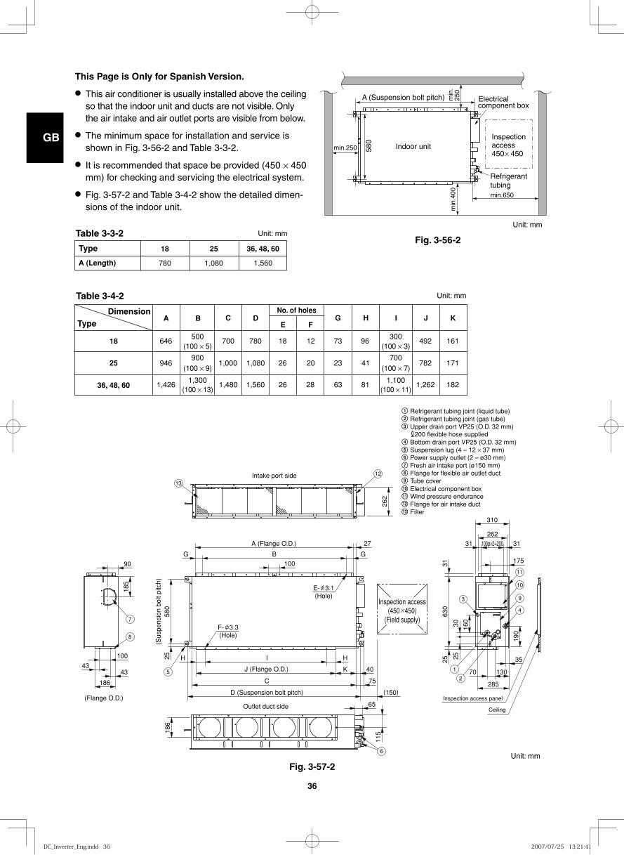
GB
FR
DE
IT
PT
GR
ES
36
Fig. 3-56-2
min.250 580
min
.400
A (Suspension bolt pitch) min
.25
0
Indoor unit
min.650
Electricalcomponent box
Inspectionaccess450 450
Refrigeranttubing
This Page is Only for Spanish Version.
● This air conditioner is usually installed above the ceiling so that the indoor unit and ducts are not visible. Only the air intake and air outlet ports are visible from below.
● The minimum space for installation and service is shown in Fig. 3-56-2 and Table 3-3-2.
● It is recommended that space be provided (450 × 450 mm) for checking and servicing the electrical system.
● Fig. 3-57-2 and Table 3-4-2 show the detailed dimen-sions of the indoor unit.
Type
A (Length)
36, 48, 60
1,560
25
1,080
18
780
DimensionType
18
25
36, 48, 60
E FG H I J K
646500
700 780 18 12 73 96 492(100 × 5)
946900
1,000 1,080 26 20 23 41 782(100 × 9)
1,4261,300
1,480 1,560 26 28 63 81 1,262
161
171
182(100 × 13)
300(100 × 3)
700(100 × 7)
1,100(100 × 11)
C DBANo. of holes
262
100
580
25 H HI
(Sus
pens
ion
bolt
pitc
h)
A (Flange O.D.)
Intake port side
(Flange O.D.)Outlet duct side
J (Flange O.D.)
27
B GG
K 40
C
D (Suspension bolt pitch)
75
(150)
11518
6
65
90
100
4343
185
186
310
262
31100p×2=20031
35
70 130
175
630
3125
190
285
160
2530
Inspection access(450 450)
(Field supply)
E- 3.1(Hole)
F- 3.3(Hole)
Inspection access panel
Ceiling
1
2
3
4
9
10
11
6
5
7
8
12
13
Unit: mm
Unit: mm
Unit: mm
Unit: mm
Refrigerant tubing joint (liquid tube)Refrigerant tubing joint (gas tube)Upper drain port VP25 (O.D. 32 mm) 200 flexible hose suppliedBottom drain port VP25 (O.D. 32 mm)Suspension lug (4 – 12 × 37 mm)Power supply outlet (2 – ø30 mm)Fresh air intake port (ø150 mm)Flange for flexible air outlet ductTube cover
Wind pressure enduranceFlange for air intake duct
11Electrical component box10
12
Filter13
Fig. 3-57-2
Table 3-4-2
Table 3-3-2
DC_Inverter_Eng.indd 36DC_Inverter_Eng.indd 36 2007/07/25 13:21:412007/07/25 13:21:41
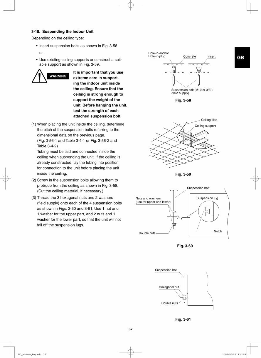
GB
FR
DE
IT
PT
GR
ES
37
Fig. 3-58
3-19. Suspending the Indoor Unit
Depending on the ceiling type:
• Insert suspension bolts as shown in Fig. 3-58
or
• Use existing ceiling supports or construct a suit-able support as shown in Fig. 3-59.
Hole-in-anchorHole-in-plug Concrete Insert
Suspension bolt (M10 or 3/8")(field supply)
Fig. 3-59
Fig. 3-60
Fig. 3-61
Ceiling tiles
Ceiling support
Suspension bolt
Suspension lugNuts and washers (use for upper and lower)
Double nutsNotch
Suspension bolt
Hexagonal nut
Double nuts
WARNINGIt is important that you use extreme care in support-ing the indoor unit inside the ceiling. Ensure that the ceiling is strong enough to support the weight of the unit. Before hanging the unit, test the strength of each attached suspension bolt.
(1) When placing the unit inside the ceiling, determine the pitch of the suspension bolts referring to the dimensional data on the previous page. (Fig. 3-56-1 and Table 3-4-1 or Fig. 3-56-2 and Table 3-4-2) Tubing must be laid and connected inside the ceiling when suspending the unit. If the ceiling is already constructed, lay the tubing into position for connection to the unit before placing the unit inside the ceiling.
(2) Screw in the suspension bolts allowing them to protrude from the ceiling as shown in Fig. 3-58. (Cut the ceiling material, if necessary.)
(3) Thread the 3 hexagonal nuts and 2 washers (field supply) onto each of the 4 suspension bolts as shown in Figs. 3-60 and 3-61. Use 1 nut and 1 washer for the upper part, and 2 nuts and 1 washer for the lower part, so that the unit will not fall off the suspension lugs.
DC_Inverter_Eng.indd 37DC_Inverter_Eng.indd 37 2007/07/25 13:21:412007/07/25 13:21:41
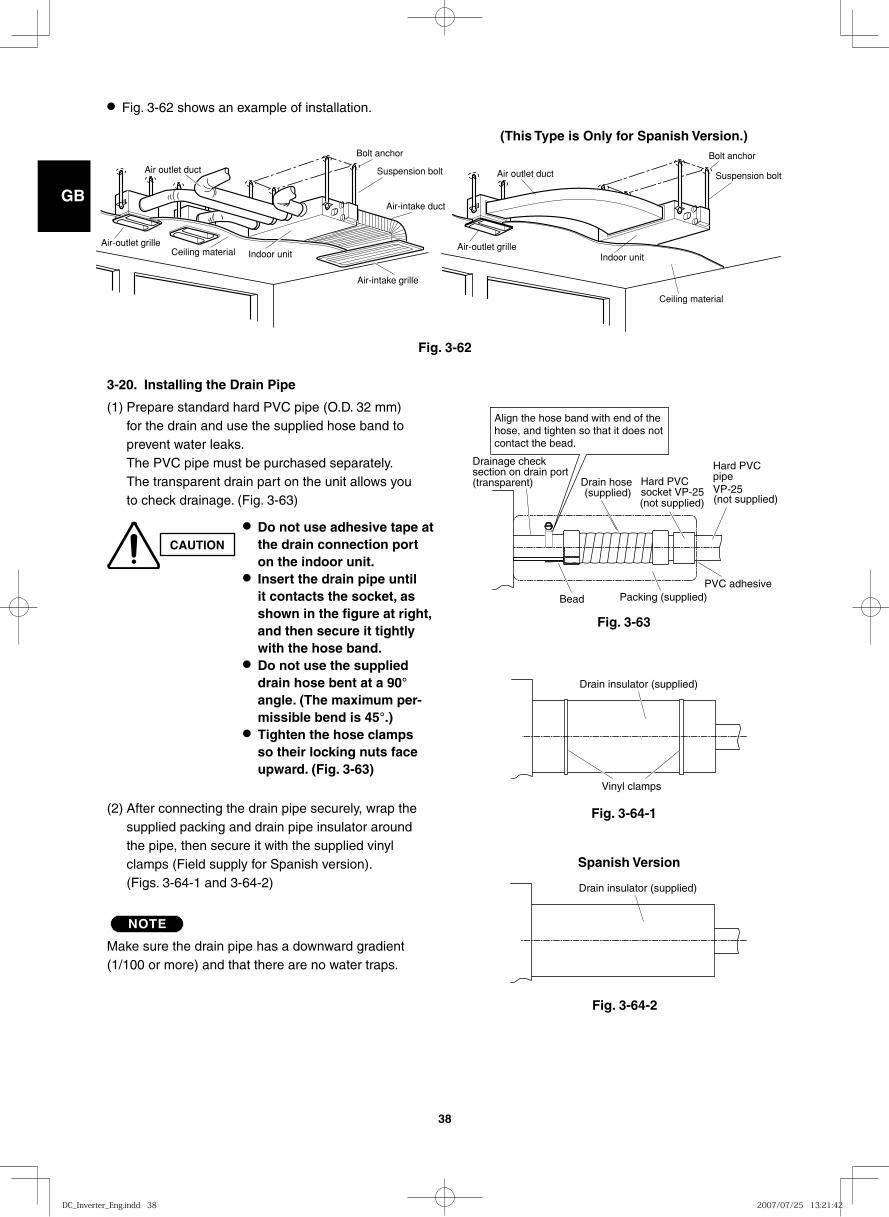
GB
FR
DE
IT
PT
GR
ES
38
● Fig. 3-62 shows an example of installation.
Air outlet duct
Air-outlet grilleCeiling material Indoor unit
Bolt anchor
Suspension bolt
Air-intake duct
Air-intake grille
Fig. 3-62
Fig. 3-63
Fig. 3-64-1
Drain hose (supplied)
(not supplied) (not supplied)
Packing (supplied)
VP-25
Align the hose band with end of the hose, and tighten so that it does not contact the bead.
Drainage check section on drain port (transparent) Hard PVC
socket VP-25
Hard PVC pipe
PVC adhesiveBead
Vinyl clamps
Drain insulator (supplied)
3-20. Installing the Drain Pipe
(1) Prepare standard hard PVC pipe (O.D. 32 mm) for the drain and use the supplied hose band to prevent water leaks.The PVC pipe must be purchased separately.The transparent drain part on the unit allows you to check drainage. (Fig. 3-63)
CAUTION
● Do not use adhesive tape at the drain connection port on the indoor unit.
● Insert the drain pipe until it contacts the socket, as shown in the figure at right, and then secure it tightly with the hose band.
● Do not use the supplied drain hose bent at a 90° angle. (The maximum per-missible bend is 45°.)
● Tighten the hose clamps so their locking nuts face upward. (Fig. 3-63)
(2) After connecting the drain pipe securely, wrap the supplied packing and drain pipe insulator around the pipe, then secure it with the supplied vinyl clamps (Field supply for Spanish version). (Figs. 3-64-1 and 3-64-2)
NOTE
Make sure the drain pipe has a downward gradient (1/100 or more) and that there are no water traps.
Air outlet duct
Air-outlet grille
Ceiling material
Indoor unit
Bolt anchor
Suspension bolt
(This Type is Only for Spanish Version.)
Fig. 3-64-2
Drain insulator (supplied)
Spanish Version
DC_Inverter_Eng.indd 38DC_Inverter_Eng.indd 38 2007/07/25 13:21:422007/07/25 13:21:42
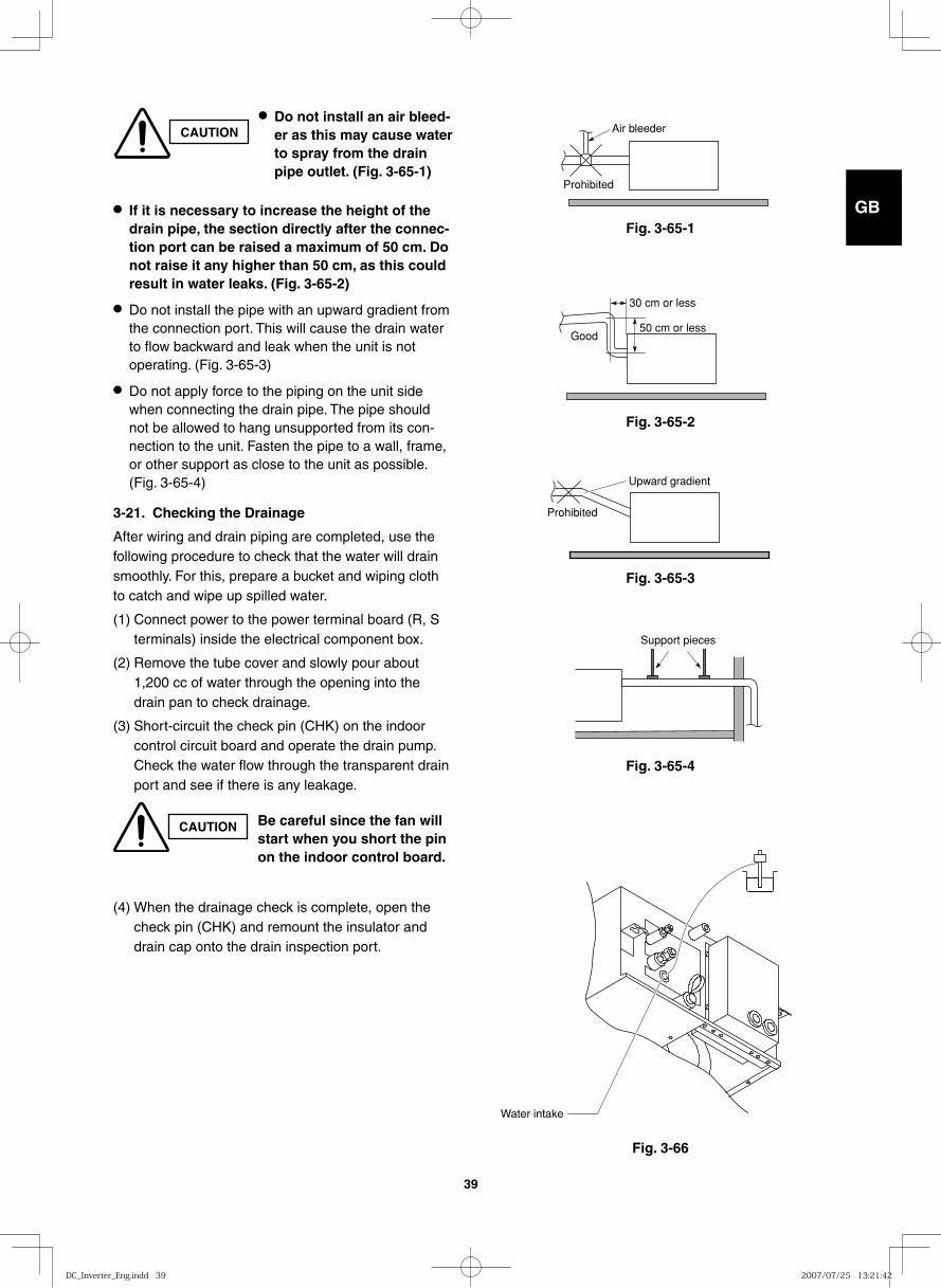
GB
FR
DE
IT
PT
GR
ES
39
Fig. 3-65-1
Fig. 3-65-2
Fig. 3-65-3
Fig. 3-65-4
Fig. 3-66
Air bleeder
Prohibited
Good
30 cm or less
50 cm or less
Prohibited
Upward gradient
Support pieces
Water intake
● If it is necessary to increase the height of the drain pipe, the section directly after the connec-tion port can be raised a maximum of 50 cm. Do not raise it any higher than 50 cm, as this could result in water leaks. (Fig. 3-65-2)
● Do not install the pipe with an upward gradient from the connection port. This will cause the drain water to flow backward and leak when the unit is not operating. (Fig. 3-65-3)
● Do not apply force to the piping on the unit side when connecting the drain pipe. The pipe should not be allowed to hang unsupported from its con-nection to the unit. Fasten the pipe to a wall, frame, or other support as close to the unit as possible. (Fig. 3-65-4)
3-21. Checking the Drainage
After wiring and drain piping are completed, use the following procedure to check that the water will drain smoothly. For this, prepare a bucket and wiping cloth to catch and wipe up spilled water.
(1) Connect power to the power terminal board (R, S terminals) inside the electrical component box.
(2) Remove the tube cover and slowly pour about 1,200 cc of water through the opening into the drain pan to check drainage.
(3) Short-circuit the check pin (CHK) on the indoor control circuit board and operate the drain pump. Check the water flow through the transparent drain port and see if there is any leakage.
(4) When the drainage check is complete, open the check pin (CHK) and remount the insulator and drain cap onto the drain inspection port.
CAUTION● Do not install an air bleed-
er as this may cause water to spray from the drain pipe outlet. (Fig. 3-65-1)
CAUTION Be careful since the fan will start when you short the pin on the indoor control board.
DC_Inverter_Eng.indd 39DC_Inverter_Eng.indd 39 2007/07/25 13:21:422007/07/25 13:21:42
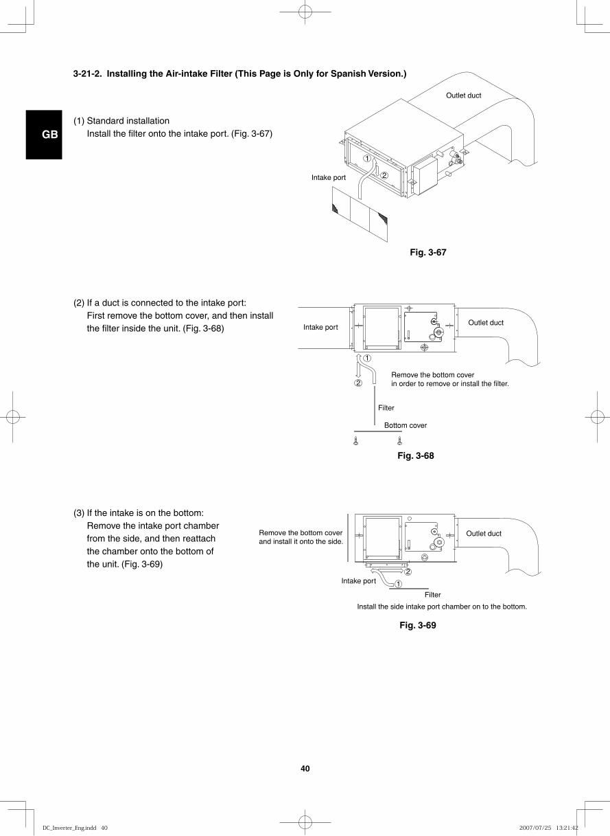
GB
FR
DE
IT
PT
GR
ES
40
(1) Standard installationInstall the filter onto the intake port. (Fig. 3-67)
(2) If a duct is connected to the intake port:First remove the bottom cover, and then install the filter inside the unit. (Fig. 3-68)
(3) If the intake is on the bottom:Remove the intake port chamber from the side, and then reattach the chamber onto the bottom of the unit. (Fig. 3-69)
Outlet duct
Intake port 2
1
Outlet ductIntake port
2
1
Remove the bottom cover in order to remove or install the filter.
Filter
Bottom cover
Outlet duct
Intake port2
1
Install the side intake port chamber on to the bottom.
Filter
Remove the bottom cover and install it onto the side.
Fig. 3-67
Fig. 3-68
Fig. 3-69
3-21-2. Installing the Air-intake Filter (This Page is Only for Spanish Version.)
DC_Inverter_Eng.indd 40DC_Inverter_Eng.indd 40 2007/07/25 13:21:422007/07/25 13:21:42
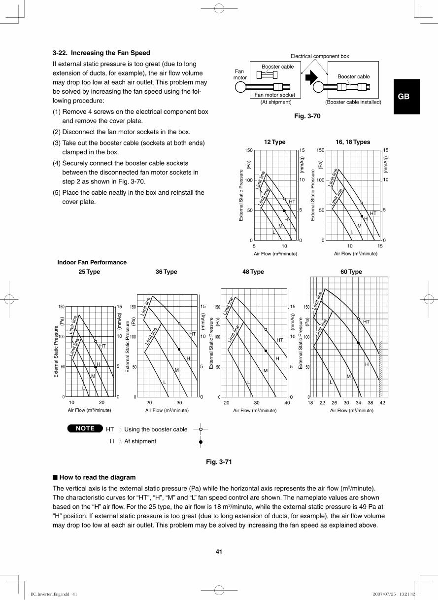
GB
FR
DE
IT
PT
GR
ES
41
NOTE HT : Using the booster cable
H : At shipment
5
Air Flow (m 3 /minute)
Ext
erna
l Sta
tic P
ress
ure
0
50
100
0
5
10
15 150
10
(mm
Aq)
(Pa)
Lim
it lin
e Lim
it lin
e
HT
H M
L
20
Air Flow (m 3 /minute)
Ext
erna
l Sta
tic P
ress
ure
0
50
0
5
10
15 150
10
Lim
it lin
e
Lim
it lin
e
HT
H
L
100
M
(mm
Aq)
(Pa)
30 40 18 22 26 30 34 38 42
Air Flow (m 3 /minute) Air Flow (m 3 /minute)
Ext
erna
l Sta
tic P
ress
ure
0
50
0
5
10
15 150
20
Lim
it lin
e
Lim
it lin
e
Lim
it lin
e
L
100
M
H
M
H
L
(mm
Aq)
(Pa)
Ext
erna
l Sta
tic P
ress
ure
0
50
150
100
(Pa)
HT
HT
30
Air Flow (m 3 /minute)
Ext
erna
l Sta
tic P
ress
ure
0
50
0
5
10
15 150
20
Lim
it lin
e
HT
L
100
M
H
Lim
it lin
e (mm
Aq)
(Pa)
15
Air Flow (m 3 /minute)
Ext
erna
l Sta
tic P
ress
ure
0
50
0
5
10
15 150
10
Lim
it lin
e
Lim
it lin
e
HT
M L
100
H
(mm
Aq)
(Pa)
16, 18 Types12 Type
Indoor Fan Performance
25 Type 36 Type 48 Type 60 Type
Lim
it lin
e
3-22. Increasing the Fan Speed
If external static pressure is too great (due to long extension of ducts, for example), the air flow volume may drop too low at each air outlet. This problem may be solved by increasing the fan speed using the fol-lowing procedure:
(1) Remove 4 screws on the electrical component box and remove the cover plate.
(2) Disconnect the fan motor sockets in the box.
(3) Take out the booster cable (sockets at both ends) clamped in the box.
(4) Securely connect the booster cable sockets between the disconnected fan motor sockets in step 2 as shown in Fig. 3-70.
(5) Place the cable neatly in the box and reinstall the cover plate.
Fig. 3-70
Booster cable
Booster cable
Electrical component box
(At shipment) (Booster cable installed)Fan motor socket
Fan motor
■ How to read the diagram
The vertical axis is the external static pressure (Pa) while the horizontal axis represents the air flow (m3/minute). The characteristic curves for “HT”, “H”, “M” and “L” fan speed control are shown. The nameplate values are shown based on the “H” air flow. For the 25 type, the air flow is 18 m3/minute, while the external static pressure is 49 Pa at “H” position. If external static pressure is too great (due to long extension of ducts, for example), the air flow volume may drop too low at each air outlet. This problem may be solved by increasing the fan speed as explained above.
NOTE
Fig. 3-71
DC_Inverter_Eng.indd 41DC_Inverter_Eng.indd 41 2007/07/25 13:21:422007/07/25 13:21:42
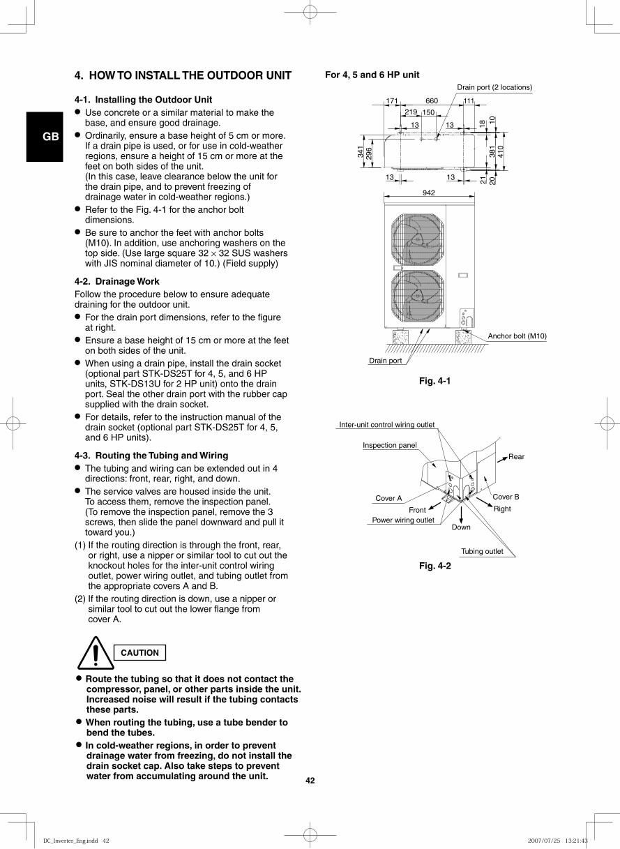
GB
FR
DE
IT
PT
GR
ES
42
Fig. 4-1
942
296
150219
13 13
2118
2010
381
410
341
1313
171 660 111
Anchor bolt (M10)
Drain port
Drain port (2 locations)
Fig. 4-2
Inter-unit control wiring outlet
Inspection panel
Cover A Cover B
Power wiring outlet
Tubing outlet
Down
Front
Rear
Right
CAUTION
● Route the tubing so that it does not contact the compressor, panel, or other parts inside the unit. Increased noise will result if the tubing contacts these parts.
● When routing the tubing, use a tube bender to bend the tubes.
● In cold-weather regions, in order to prevent drainage water from freezing, do not install the drain socket cap. Also take steps to prevent water from accumulating around the unit.
4-1. Installing the Outdoor Unit● Use concrete or a similar material to make the
base, and ensure good drainage.● Ordinarily, ensure a base height of 5 cm or more.
If a drain pipe is used, or for use in cold-weather regions, ensure a height of 15 cm or more at the feet on both sides of the unit. (In this case, leave clearance below the unit for the drain pipe, and to prevent freezing of drainage water in cold-weather regions.)
● Refer to the Fig. 4-1 for the anchor bolt dimensions.
● Be sure to anchor the feet with anchor bolts (M10). In addition, use anchoring washers on the top side. (Use large square 32 × 32 SUS washers with JIS nominal diameter of 10.) (Field supply)
4-2. Drainage WorkFollow the procedure below to ensure adequate draining for the outdoor unit.● For the drain port dimensions, refer to the figure
at right.● Ensure a base height of 15 cm or more at the feet
on both sides of the unit.● When using a drain pipe, install the drain socket
(optional part STK-DS25T for 4, 5, and 6 HP units, STK-DS13U for 2 HP unit) onto the drain port. Seal the other drain port with the rubber cap supplied with the drain socket.
● For details, refer to the instruction manual of the drain socket (optional part STK-DS25T for 4, 5, and 6 HP units).
4-3. Routing the Tubing and Wiring● The tubing and wiring can be extended out in 4
directions: front, rear, right, and down.● The service valves are housed inside the unit.
To access them, remove the inspection panel. (To remove the inspection panel, remove the 3 screws, then slide the panel downward and pull it toward you.)
(1) If the routing direction is through the front, rear, or right, use a nipper or similar tool to cut out the knockout holes for the inter-unit control wiring outlet, power wiring outlet, and tubing outlet from the appropriate covers A and B.
(2) If the routing direction is down, use a nipper or similar tool to cut out the lower flange from cover A.
4. HOW TO INSTALL THE OUTDOOR UNIT For 4, 5 and 6 HP unit
DC_Inverter_Eng.indd 42DC_Inverter_Eng.indd 42 2007/07/25 13:21:432007/07/25 13:21:43
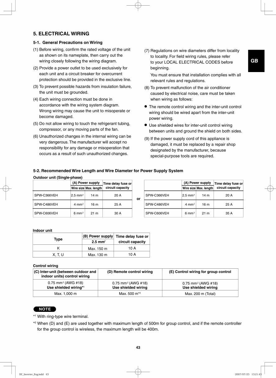
GB
FR
DE
IT
PT
GR
ES
43
Control wiring
(C) Inter-unit (between outdoor and indoor units) control wiring
(D) Remote control wiring (E) Control wiring for group control
0.75 mm2 (AWG #18) 0.75 mm2 (AWG #18) 0.75 mm2 (AWG #18)Use shielded wiring*1 Use shielded wiring Use shielded wiring
Max. 1,000 m Max. 500 m*2 Max. 200 m (Total)
5. ELECTRICAL WIRING
5-1. General Precautions on Wiring
(1) Before wiring, confirm the rated voltage of the unit as shown on its nameplate, then carry out the wiring closely following the wiring diagram.
(2) Provide a power outlet to be used exclusively for each unit and a circuit breaker for overcurrent protection should be provided in the exclusive line.
(3) To prevent possible hazards from insulation failure, the unit must be grounded.
(4) Each wiring connection must be done in accordance with the wiring system diagram. Wrong wiring may cause the unit to misoperate or become damaged.
(5) Do not allow wiring to touch the refrigerant tubing, compressor, or any moving parts of the fan.
(6) Unauthorized changes in the internal wiring can be very dangerous. The manufacturer will accept no responsibility for any damage or misoperation that occurs as a result of such unauthorized changes.
(7) Regulations on wire diameters differ from locality to locality. For field wiring rules, please refer to your LOCAL ELECTRICAL CODES before beginning.
You must ensure that installation complies with all relevant rules and regulations.
(8) To prevent malfunction of the air conditioner caused by electrical noise, care must be taken when wiring as follows:
● The remote control wiring and the inter-unit control wiring should be wired apart from the inter-unit power wiring.
● Use shielded wires for inter-unit control wiring between units and ground the shield on both sides.
(9) If the power supply cord of this appliance is damaged, it must be replaced by a repair shop designated by the manufacturer, because special-purpose tools are required.
5-2. Recommended Wire Length and Wire Diameter for Power Supply System
Outdoor unit (Single-phase) (A) Power supply
Wire size Max. length
SPW-C366VEH
SPW-C486VEH
SPW-C606VEH
14 m 20 Aor
16 m 25 A
21 m 30 A
2.5 mm2
4 mm2
6 mm2
Time delay fuse or (A) Power supply
Wire size
SPW-C366VEH
SPW-C486VEH
SPW-C606VEH
14 m 20 A
16 m 25 A
21 m 35 A
2.5 mm2
4 mm2
6 mm2
Time delay fuse orcircuit capacity Max. length circuit capacity
NOTE
*1 With ring-type wire terminal.
*2 When (D) and (E) are used together with maximum length of 500m for group control, and if the remote controller for the group control is wireless, the maximum length will be 400m.
Indoor unit
Time delay fuse orcircuit capacity
(B) Power supply
2.5 mm2
K
X, T, U
Type
Max. 150 m
Max. 130 m
10 A
10 A
DC_Inverter_Eng.indd 43DC_Inverter_Eng.indd 43 2007/07/25 13:21:432007/07/25 13:21:43
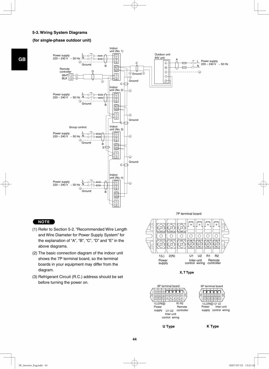
GB
FR
DE
IT
PT
GR
ES
44
5-3. Wiring System Diagrams
U2
U1
L
N
1
2
U2
U1
1
2
U2
U1
1
2
U2
U1
1
2
Group control:
2
1 WHT
Remote controller D
A
E
Indoor unit (No. n)
Indoor unit (No. 1)
Indoor unit (No. 2)
Indoor unit (No. 3)
C
B
L
N Ground
L N
L N
L N
L N
BLK 2
1
B
B
B
Ground
Ground
Ground
Power supply 220 – 240 V ~ 50 Hz
Power supply 220 – 240 V ~ 50 Hz
Power supply 220 – 240 V ~ 50 Hz
Power supply 220 – 240 V ~ 50 Hz
Power supply 220 – 240 V ~ 50 Hz
Ground
C Ground
C Ground
C
Ground
2
1
N
L
Outdoor unit INV unit
L
N
L
N
L
N
NOTE
(1) Refer to Section 5-2. “Recommended Wire Length and Wire Diameter for Power Supply System” for the explanation of “A”, “B”, “C”, “D” and “E” in the above diagrams.
(2) The basic connection diagram of the indoor unit shows the 7P terminal board, so the terminal boards in your equipment may differ from the diagram.
(3) Refrigerant Circuit (R.C.) address should be set before turning the power on.
1(L)2(N)Power supply U1
Inter-unitcontrol wiring
U2Remote controller
8P terminal board
R1 R21 2 U1 U2 R1 R2
U Type K Type
1(L)2(N)1 2 3 4 5
Power supply
Inter-unitcontrol wiring
5P terminal board
U1 U2
1(L) 2(N)Power supply
U1Inter-unit
control wiring
U2Remote controller
R1 R2
X, T Type
7P terminal board
(for single-phase outdoor unit)
DC_Inverter_Eng.indd 44DC_Inverter_Eng.indd 44 2007/07/25 13:21:432007/07/25 13:21:43
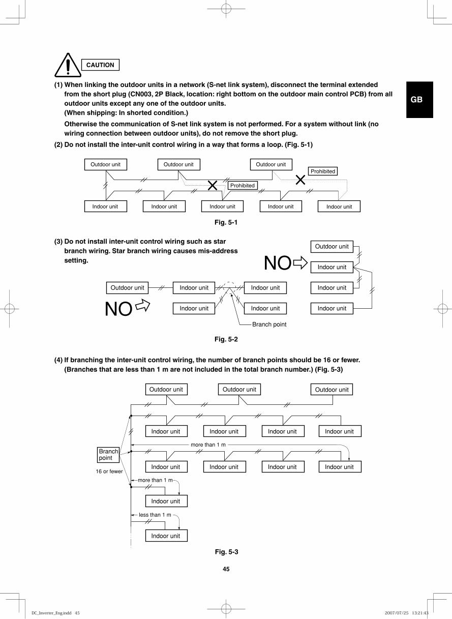
GB
FR
DE
IT
PT
GR
ES
45
Outdoor unit Outdoor unit Outdoor unit
Indoor unit Indoor unit Indoor unit Indoor unit
Indoor unit
more than 1 m
more than 1 mBranchpoint
16 or fewer
Indoor unit
Indoor unit Indoor unit Indoor unit
less than 1 m
Indoor unit
Outdoor unit Indoor unit Indoor unit Indoor unit
Indoor unit Indoor unit Indoor unit
Outdoor unit
Indoor unit
NO
NO
Branch point
(1) When linking the outdoor units in a network (S-net link system), disconnect the terminal extended from the short plug (CN003, 2P Black, location: right bottom on the outdoor main control PCB) from all outdoor units except any one of the outdoor units. (When shipping: In shorted condition.)
Otherwise the communication of S-net link system is not performed. For a system without link (no wiring connection between outdoor units), do not remove the short plug.
(2) Do not install the inter-unit control wiring in a way that forms a loop. (Fig. 5-1)
Outdoor unit Outdoor unit Outdoor unitProhibited
Prohibited
Indoor unit Indoor unit Indoor unit Indoor unit Indoor unit
Fig. 5-1
Fig. 5-2
Fig. 5-3
CAUTION
(3) Do not install inter-unit control wiring such as star branch wiring. Star branch wiring causes mis-address setting.
(4) If branching the inter-unit control wiring, the number of branch points should be 16 or fewer. (Branches that are less than 1 m are not included in the total branch number.) (Fig. 5-3)
DC_Inverter_Eng.indd 45DC_Inverter_Eng.indd 45 2007/07/25 13:21:432007/07/25 13:21:43
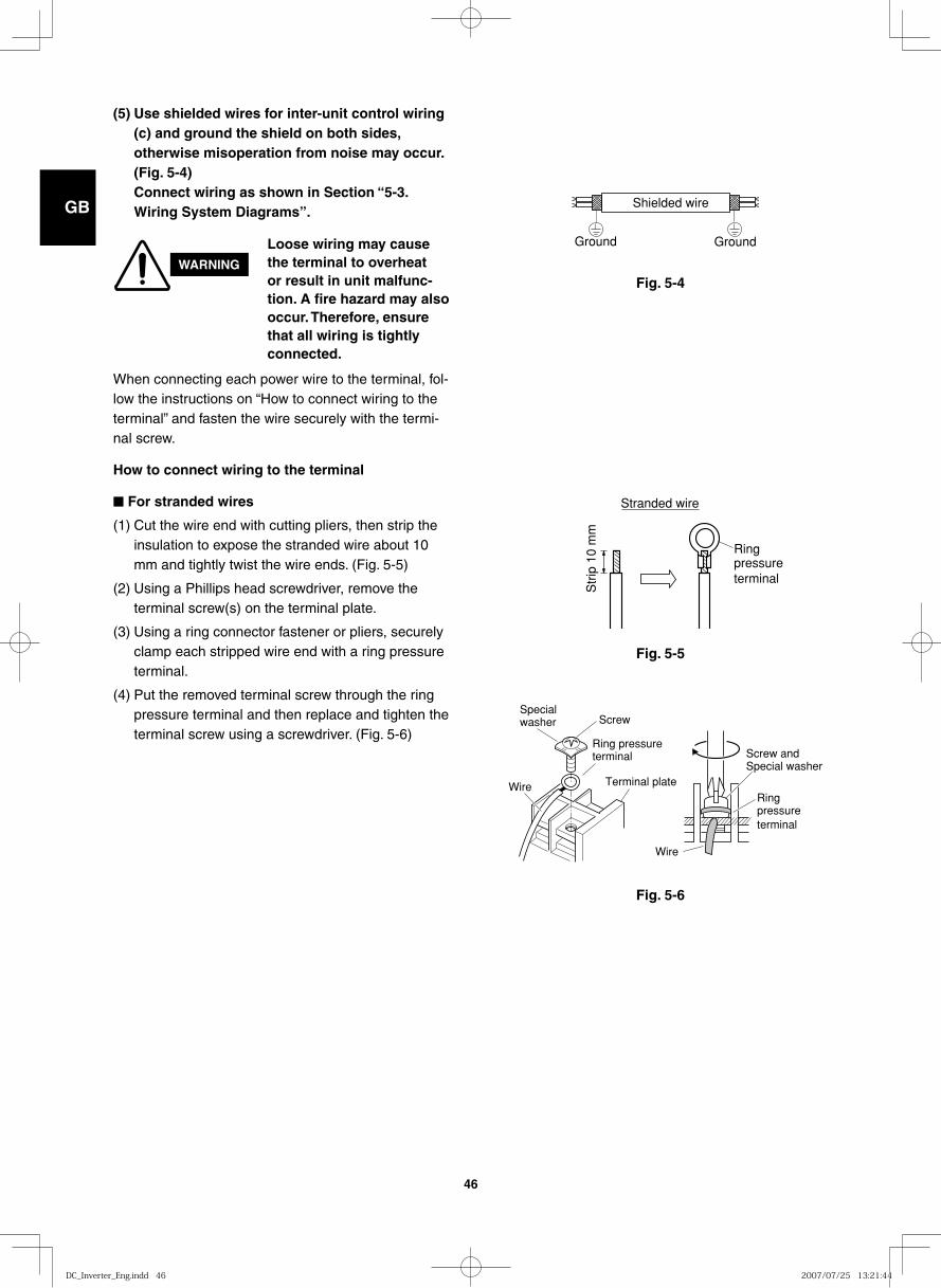
GB
FR
DE
IT
PT
GR
ES
46
Fig. 5-4
Shielded wire
Ground Ground
Fig. 5-5
Stranded wire
Ringpressure terminal
Str
ip 1
0 m
m
Fig. 5-6
Wire
Specialwasher Screw
Ring pressure terminal
Terminal plate
Screw and Special washer
Ring pressure terminal
Wire
(5) Use shielded wires for inter-unit control wiring (c) and ground the shield on both sides, otherwise misoperation from noise may occur. (Fig. 5-4)Connect wiring as shown in Section “5-3. Wiring System Diagrams”.
WARNING
Loose wiring may cause the terminal to overheat or result in unit malfunc-tion. A fire hazard may also occur. Therefore, ensure that all wiring is tightly connected.
When connecting each power wire to the terminal, fol-low the instructions on “How to connect wiring to the terminal” and fasten the wire securely with the termi-nal screw.
How to connect wiring to the terminal
■ For stranded wires
(1) Cut the wire end with cutting pliers, then strip the insulation to expose the stranded wire about 10 mm and tightly twist the wire ends. (Fig. 5-5)
(2) Using a Phillips head screwdriver, remove the terminal screw(s) on the terminal plate.
(3) Using a ring connector fastener or pliers, securely clamp each stripped wire end with a ring pressure terminal.
(4) Put the removed terminal screw through the ring pressure terminal and then replace and tighten the terminal screw using a screwdriver. (Fig. 5-6)
DC_Inverter_Eng.indd 46DC_Inverter_Eng.indd 46 2007/07/25 13:21:442007/07/25 13:21:44
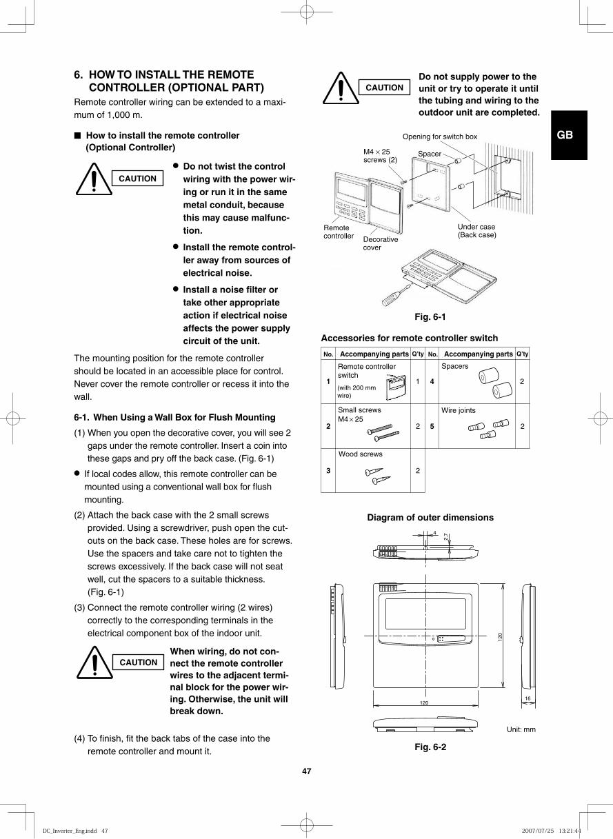
GB
FR
DE
IT
PT
GR
ES
47
Fig. 6-2
120
120
4
2.7
16
Diagram of outer dimensions
6. HOW TO INSTALL THE REMOTE CONTROLLER (OPTIONAL PART)Remote controller wiring can be extended to a maxi-mum of 1,000 m.
■ How to install the remote controller (Optional Controller)
CAUTION
● Do not twist the control wiring with the power wir-ing or run it in the same metal conduit, because this may cause malfunc-tion.
● Install the remote control-ler away from sources of electrical noise.
● Install a noise filter or take other appropriate action if electrical noise affects the power supply circuit of the unit.
The mounting position for the remote controller should be located in an accessible place for control. Never cover the remote controller or recess it into the wall.
6-1. When Using a Wall Box for Flush Mounting
(1) When you open the decorative cover, you will see 2 gaps under the remote controller. Insert a coin into these gaps and pry off the back case. (Fig. 6-1)
● If local codes allow, this remote controller can be mounted using a conventional wall box for flush mounting.
(2) Attach the back case with the 2 small screws provided. Using a screwdriver, push open the cut-outs on the back case. These holes are for screws. Use the spacers and take care not to tighten the screws excessively. If the back case will not seat well, cut the spacers to a suitable thickness. (Fig. 6-1)
(3) Connect the remote controller wiring (2 wires) correctly to the corresponding terminals in the electrical component box of the indoor unit.
(4) To finish, fit the back tabs of the case into the remote controller and mount it.
CAUTIONWhen wiring, do not con-nect the remote controller wires to the adjacent termi-nal block for the power wir-ing. Otherwise, the unit will break down.
CAUTIONDo not supply power to the unit or try to operate it until the tubing and wiring to the outdoor unit are completed.
Fig. 6-1
Opening for switch box
Under case(Back case)
M4 × 25screws (2)
Remotecontroller Decorative
cover
Spacer
1
2 2
3 2
Remote controller switch
(with 200 mm wire)
Small screwsM4 × 25
Wood screws
4 2
5 2
Spacers
Wire joints
1
Accompanying partsAccompanying parts No.No. Q’tyQ’ty
Accessories for remote controller switch
Unit: mm
DC_Inverter_Eng.indd 47DC_Inverter_Eng.indd 47 2007/07/25 13:21:442007/07/25 13:21:44
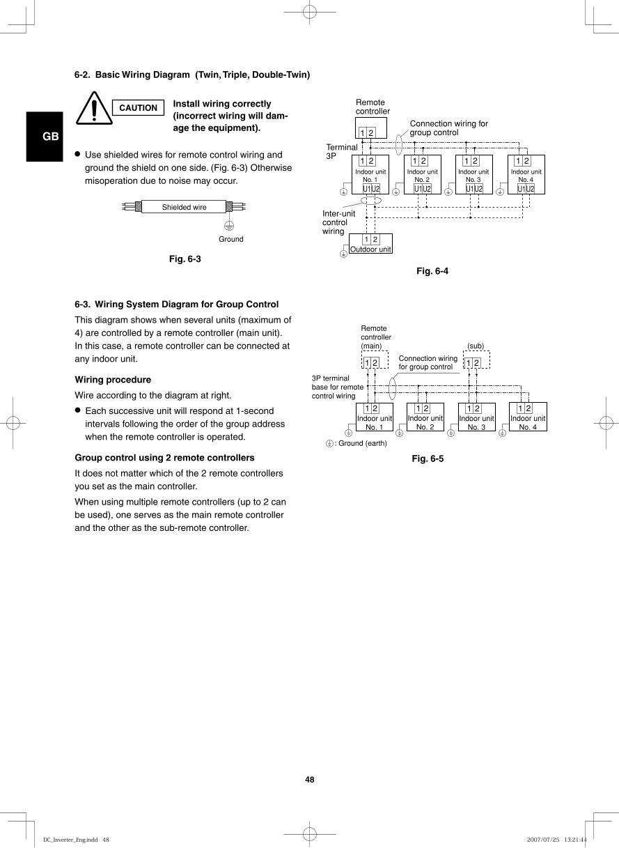
GB
FR
DE
IT
PT
GR
ES
48
6-2. Basic Wiring Diagram (Twin, Triple, Double-Twin)
CAUTION Install wiring correctly (incorrect wiring will dam-age the equipment).
● Use shielded wires for remote control wiring and ground the shield on one side. (Fig. 6-3) Otherwise misoperation due to noise may occur.
Fig. 6-3Fig. 6-4
Shielded wire
Ground
6-3. Wiring System Diagram for Group Control
This diagram shows when several units (maximum of 4) are controlled by a remote controller (main unit). In this case, a remote controller can be connected at any indoor unit.
Wiring procedure
Wire according to the diagram at right.
● Each successive unit will respond at 1-second intervals following the order of the group address when the remote controller is operated.
Group control using 2 remote controllers
It does not matter which of the 2 remote controllers you set as the main controller.
When using multiple remote controllers (up to 2 can be used), one serves as the main remote controller and the other as the sub-remote controller.
U1U2
1
1 2
U1U2
1
U1U2
1
U1U2
1
Outdoor unit
Indoor unitNo. 4
Indoor unitNo. 3
Indoor unitNo. 2
Indoor unitNo. 1
1
Remotecontroller
Connection wiring forgroup control
Inter-unitcontrolwiring
Terminal3P
2
2 2 2 2
(sub)
3P terminal base for remote control wiring
Remotecontroller(main)
1Indoor unit
No. 1
: Ground (earth)
Indoor unitNo. 2
Indoor unitNo. 4
Indoor unitNo. 3
Connection wiring for group control
1 1
1 2
2 2 21
21
2
Fig. 6-5
DC_Inverter_Eng.indd 48DC_Inverter_Eng.indd 48 2007/07/25 13:21:442007/07/25 13:21:44
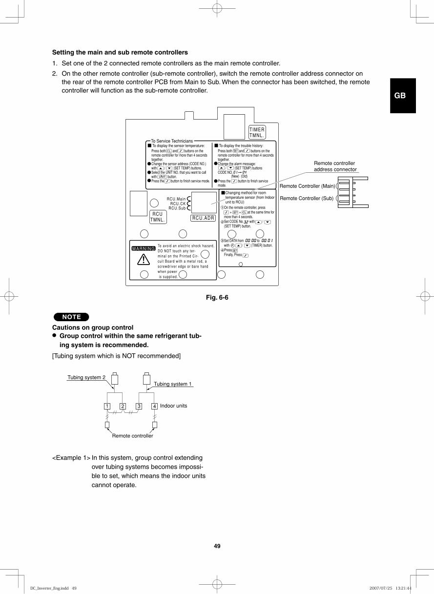
GB
FR
DE
IT
PT
GR
ES
49
NOTE
Cautions on group control● Group control within the same refrigerant tub-
ing system is recommended.
[Tubing system which is NOT recommended]
<Example 1> In this system, group control extending over tubing systems becomes impossi-ble to set, which means the indoor units cannot operate.
1 2 3 4
Tubing system 2Tubing system 1
Indoor units
Remote controller
TIMERTMNL.
RCUTMNL. RCU.ADR
RCU.Main
RCU.SubRCU.CK
To Service TechniciansTo display the sensor temperature:
WARNINGTo avoid an e lect r ic shock hazard,DO NOT touch any ter -mina l on the Pr in ted Ci r -cu i t Board wi th a meta l rod, ascrewdr iver edge or bare handwhen power is suppl ied.
Press both and buttons on the remote controller for more than 4 seconds together.Change the sensor address (CODE NO.) with / (SET TEMP) buttons.Select the UNIT NO. that you want to call with button.Press the button to finish service mode.
To display the trouble history:Press both and buttons on the remote controller for more than 4 seconds together.Change the alarm message: / (SET TEMP) buttonsCODE NO.
Press the button to finish service mode.
On the remote controller, press + + at the same time for more than 4 seconds.Set CODE No. with /(SET TEMP) button.
Set DATA from towith / (TIMER) button.PressFinally, Press
(New) (Old)
Changing method for room temperature sensor (from Indoor unit to RCU)
1
2
3
4
Remote Controller (Sub)
Remote controller address connector
Remote Controller (Main)
Setting the main and sub remote controllers
1. Set one of the 2 connected remote controllers as the main remote controller.
2. On the other remote controller (sub-remote controller), switch the remote controller address connector on the rear of the remote controller PCB from Main to Sub. When the connector has been switched, the remote controller will function as the sub-remote controller.
Fig. 6-6
DC_Inverter_Eng.indd 49DC_Inverter_Eng.indd 49 2007/07/25 13:21:442007/07/25 13:21:44
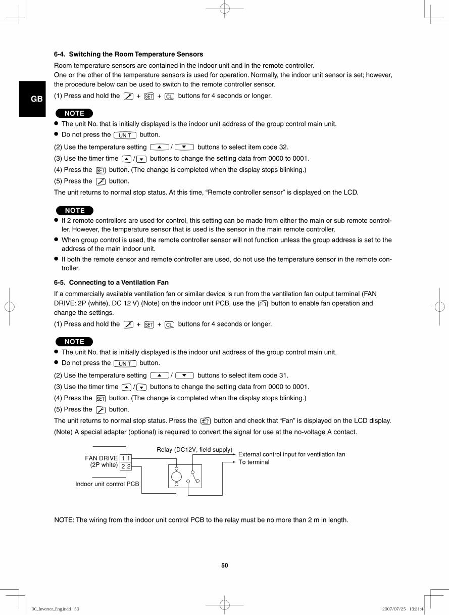
GB
FR
DE
IT
PT
GR
ES
50
6-4. Switching the Room Temperature Sensors
Room temperature sensors are contained in the indoor unit and in the remote controller. One or the other of the temperature sensors is used for operation. Normally, the indoor unit sensor is set; however, the procedure below can be used to switch to the remote controller sensor.
(1) Press and hold the + + buttons for 4 seconds or longer.
NOTE● The unit No. that is initially displayed is the indoor unit address of the group control main unit.● Do not press the button.
(2) Use the temperature setting / buttons to select item code 32.
(3) Use the timer time / buttons to change the setting data from 0000 to 0001.
(4) Press the button. (The change is completed when the display stops blinking.)
(5) Press the button.
The unit returns to normal stop status. At this time, “Remote controller sensor” is displayed on the LCD.
NOTE● If 2 remote controllers are used for control, this setting can be made from either the main or sub remote control-
ler. However, the temperature sensor that is used is the sensor in the main remote controller.● When group control is used, the remote controller sensor will not function unless the group address is set to the
address of the main indoor unit.● If both the remote sensor and remote controller are used, do not use the temperature sensor in the remote con-
troller.
6-5. Connecting to a Ventilation Fan
If a commercially available ventilation fan or similar device is run from the ventilation fan output terminal (FAN DRIVE: 2P (white), DC 12 V) (Note) on the indoor unit PCB, use the button to enable fan operation and change the settings.
(1) Press and hold the + + buttons for 4 seconds or longer.
NOTE● The unit No. that is initially displayed is the indoor unit address of the group control main unit.● Do not press the button.
(2) Use the temperature setting / buttons to select item code 31.
(3) Use the timer time / buttons to change the setting data from 0000 to 0001.
(4) Press the button. (The change is completed when the display stops blinking.)
(5) Press the button.
The unit returns to normal stop status. Press the button and check that “Fan” is displayed on the LCD display.
(Note) A special adapter (optional) is required to convert the signal for use at the no-voltage A contact.
1 12 2
Relay (DC12V, field supply)External control input for ventilation fan
Indoor unit control PCB
FAN DRIVE(2P white) To terminal
NOTE: The wiring from the indoor unit control PCB to the relay must be no more than 2 m in length.
DC_Inverter_Eng.indd 50DC_Inverter_Eng.indd 50 2007/07/25 13:21:442007/07/25 13:21:44
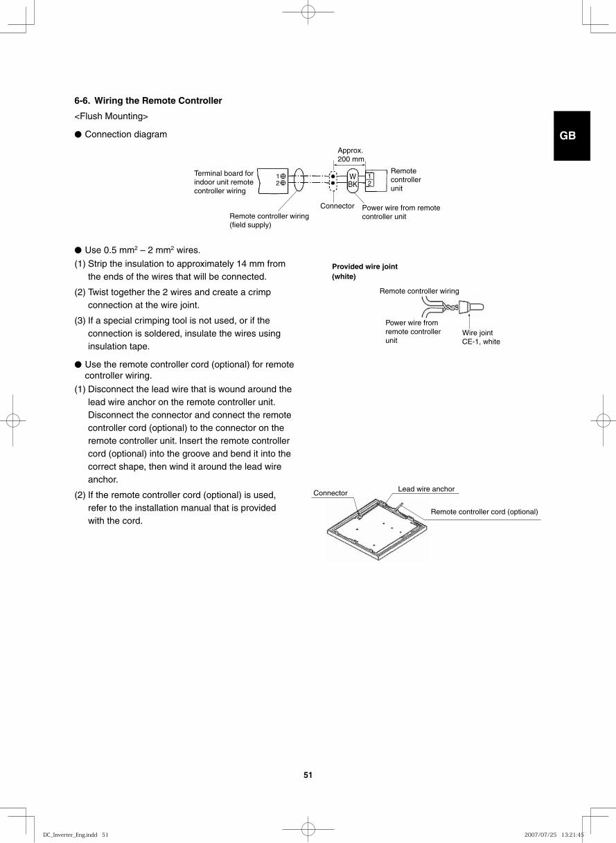
GB
FR
DE
IT
PT
GR
ES
51
6-6. Wiring the Remote Controller
<Flush Mounting>
● Connection diagram
● Use 0.5 mm2 – 2 mm2 wires.
(1) Strip the insulation to approximately 14 mm from the ends of the wires that will be connected.
(2) Twist together the 2 wires and create a crimp connection at the wire joint.
(3) If a special crimping tool is not used, or if the connection is soldered, insulate the wires using insulation tape.
● Use the remote controller cord (optional) for remote controller wiring.
(1) Disconnect the lead wire that is wound around the lead wire anchor on the remote controller unit. Disconnect the connector and connect the remote controller cord (optional) to the connector on the remote controller unit. Insert the remote controller cord (optional) into the groove and bend it into the correct shape, then wind it around the lead wire anchor.
(2) If the remote controller cord (optional) is used, refer to the installation manual that is provided with the cord.
Terminal board for indoor unit remote controller wiring
12
12
WBK
Remote controller wiring (field supply)
Connector
Remote controller unit
Power wire from remote controller unit
Approx. 200 mm
Remote controller wiring
Power wire from remote controller unit
Provided wire joint (white)
Wire jointCE-1, white
Remote controller cord (optional)
Connector Lead wire anchor
DC_Inverter_Eng.indd 51DC_Inverter_Eng.indd 51 2007/07/25 13:21:452007/07/25 13:21:45
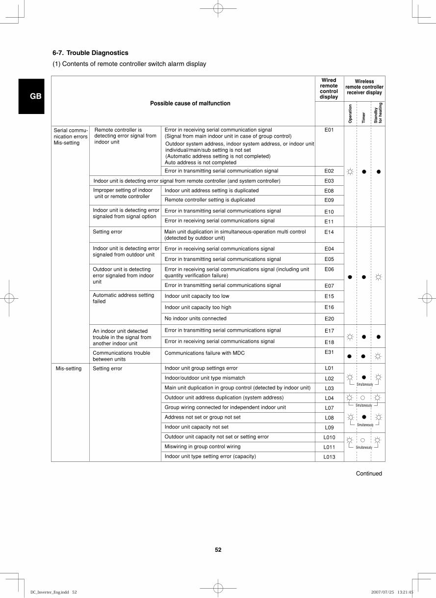
GB
FR
DE
IT
PT
GR
ES
52
6-7. Trouble Diagnostics
(1) Contents of remote controller switch alarm display
Remote controller is detecting error signal from indoor unit
E01
E02
E10
E11
E14
E03
E08
E09
E04
E05
E06
E07
E15
E16
E20
E17
E18
E31
L01
L02
L03
L04
L07
L08
L09
L010
L011
L013
Indoor unit is detecting error signal from remote controller (and system controller)
Error in receiving serial communication signal(Signal from main indoor unit in case of group control)
Auto address is not completed
Outdoor system address, indoor system address, or indoor unit individual/main/sub setting is not set (Automatic address setting is not completed)
Error in transmitting serial communication signal
Improper setting of indoor unit or remote controller
Indoor unit address setting is duplicated
Remote controller setting is duplicated
Error in transmitting serial communications signal
Error in transmitting serial communications signal
Error in receiving serial communications signal
Error in receiving serial communications signal
Indoor unit is detecting error signaled from signal option
Setting error Main unit duplication in simultaneous-operation multi control (detected by outdoor unit)
Indoor unit is detecting error signaled from outdoor unit
Outdoor unit is detecting error signaled from indoorunit
Automatic address setting failed
An indoor unit detected trouble in the signal from another indoor unit
Communications trouble between units
Setting errorMis-setting
Continued
Error in transmitting serial communications signal
Indoor unit capacity too low
Indoor unit capacity too high
No indoor units connected
Error in receiving serial communications signal
Communications failure with MDC
Indoor unit group settings error
Indoor/outdoor unit type mismatch
Main unit duplication in group control (detected by indoor unit)
Outdoor unit address duplication (system address)
Group wiring connected for independent indoor unit
Address not set or group not set
Indoor unit capacity not set
Outdoor unit capacity not set or setting error
Miswiring in group control wiring
Indoor unit type setting error (capacity)
Error in transmitting serial communications signal
Error in receiving serial communications signal (including unit quantity verification failure)
Simultaneously
Simultaneously
Simultaneously
Simultaneously
Serial commu-nication errorsMis-setting
Wiredremotecontroldisplay
Wirelessremote controllerreceiver display
Op
erat
ion
Tim
er
Sta
nd
by
for
hea
tin
gPossible cause of malfunction
DC_Inverter_Eng.indd 52DC_Inverter_Eng.indd 52 2007/07/25 13:21:452007/07/25 13:21:45
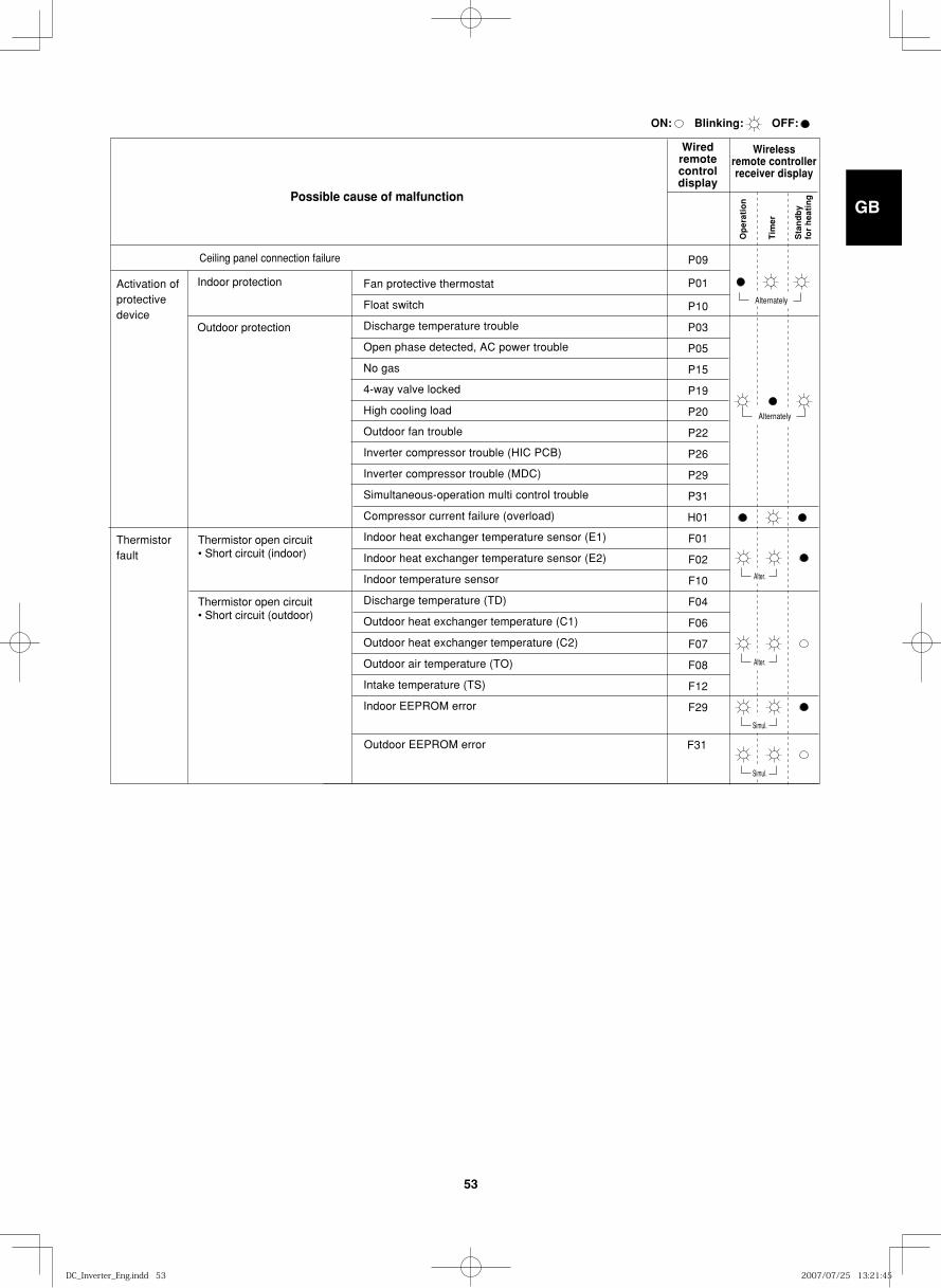
GB
FR
DE
IT
PT
GR
ES
53
P09
P01
P10
P03
P05
P15
P19
P20
P22
P26
P29
P31
H01
F01
F02
F10
F04
F06
F07
F08
F12
F29
Ceiling panel connection failure
Indoor protection Fan protective thermostat
Float switch
Discharge temperature trouble
Open phase detected, AC power trouble
No gas
4-way valve locked
High cooling load
Outdoor fan trouble
Inverter compressor trouble (HIC PCB)
Inverter compressor trouble (MDC)
Simultaneous-operation multi control trouble
Compressor current failure (overload)
Indoor heat exchanger temperature sensor (E1)
Indoor heat exchanger temperature sensor (E2)
Indoor temperature sensor
Discharge temperature (TD)
Outdoor heat exchanger temperature (C1)
Outdoor heat exchanger temperature (C2)
Outdoor air temperature (TO)
Intake temperature (TS)
Indoor EEPROM error
Outdoor protection
Thermistor open circuit• Short circuit (indoor)
Thermistor open circuit• Short circuit (outdoor)
Activation ofprotectivedevice
Thermistorfault
Alternately
Alter.
Simul.
Alter.
Simul.
Alternately
Outdoor EEPROM error F31
Wiredremotecontroldisplay
Wirelessremote controllerreceiver display
ON:
Op
erat
ion
Tim
er
Sta
nd
by
for
hea
tin
g
Blinking: OFF:
Possible cause of malfunction
DC_Inverter_Eng.indd 53DC_Inverter_Eng.indd 53 2007/07/25 13:21:452007/07/25 13:21:45
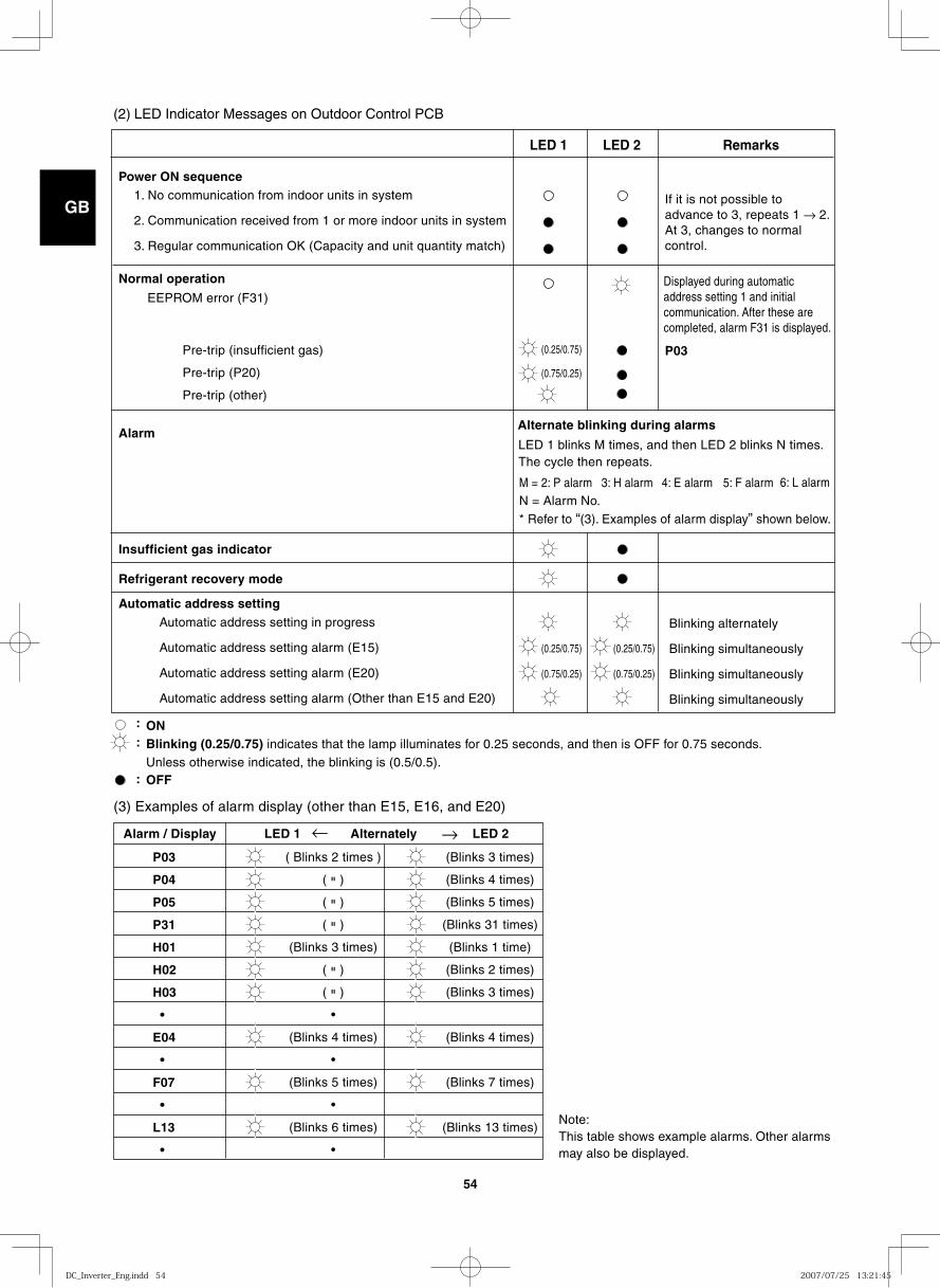
GB
FR
DE
IT
PT
GR
ES
54
(2) LED Indicator Messages on Outdoor Control PCB
Power ON sequence 1. No communication from indoor units in system
2. Communication received from 1 or more indoor units in system
3. Regular communication OK (Capacity and unit quantity match)
If it is not possible to advance to 3, repeats 1 → 2. At 3, changes to normal control.
P03
Normal operation
Pre-trip (insufficient gas)
Pre-trip (P20)
Pre-trip (other)
Automatic address setting in progress
Automatic address setting alarm (E15)
Automatic address setting alarm (E20)
Automatic address setting alarm (Other than E15 and E20)
Note: This table shows example alarms. Other alarms may also be displayed.
(0.25/0.75)
(0.75/0.25)
EEPROM error (F31)
Blinking alternately
Blinking simultaneously
Blinking simultaneously
Blinking simultaneously
Alarm LED 1 blinks M times, and then LED 2 blinks N times.The cycle then repeats.
M = 2: P alarm 6: L alarm N = Alarm No. * Refer to “(3). Examples of alarm display” shown below.
3: H alarm 4: E alarm 5: F alarm
Alternate blinking during alarms
Insufficient gas indicator
(0.25/0.75)
(0.75/0.25)
(0.25/0.75)
(0.75/0.25)
Refrigerant recovery mode Automatic address setting
Displayed during automatic address setting 1 and initial communication. After these are completed, alarm F31 is displayed.
P03
P04
P05
P31
H01
H02
H03
•
E04
•
F07
•
L13
•
( Blinks 2 times )
( " )
( " )
( " )
(Blinks 3 times)
( " )
( " )
•
(Blinks 4 times)
•
(Blinks 5 times)
•
(Blinks 6 times)
•
(Blinks 3 times)
(Blinks 4 times)
(Blinks 5 times)
(Blinks 31 times)
(Blinks 1 time)
(Blinks 2 times)
(Blinks 3 times)
(Blinks 4 times)
(Blinks 7 times)
(Blinks 13 times)
Alarm / Display LED 1 Alternately
→ → LED 2
ON
:
:
:
LED 1 LED 2 Remarks
OFF
(3) Examples of alarm display (other than E15, E16, and E20)
Blinking (0.25/0.75) indicates that the lamp illuminates for 0.25 seconds, and then is OFF for 0.75 seconds. Unless otherwise indicated, the blinking is (0.5/0.5).
DC_Inverter_Eng.indd 54DC_Inverter_Eng.indd 54 2007/07/25 13:21:452007/07/25 13:21:45

GB
FR
DE
IT
PT
GR
ES
55
7. HOW TO PROCESS TUBING
The liquid tubing side is connected by a flare nut, and the gas tubing side is connected by brazing.
7-1. Connecting the Refrigerant Tubing
Use of the Flaring Method
Many of conventional split system air conditioners employ the flaring method to connect refrigerant tubes that run between indoor and outdoor units. In this meth-od, the copper tubes are flared at each end and con-nected with flare nuts.
Flaring Procedure with a Flare Tool
(1) Cut the copper tube to the required length with a tube cutter. It is recommended to cut approx. 30 – 50 cm longer than the tubing length you estimate.
(2) Remove burrs at each end of the copper tubing with a tube reamer or file. This process is impor-tant and should be done carefully to make a good flare. Be sure to keep any contaminants (moisture, dirt, metal filings, etc.) from entering the tubing. (Figs. 7-1 and 7-2)
NOTE
When reaming, hold the tube end downward and be sure that no copper scraps fall into the tube. (Fig. 7-2)
(3) Remove the flare nut from the unit and be sure to mount it on the copper tube.
(4) Make a flare at the end of the copper tube with a flare tool.* (Fig. 7-3)
*Use “RIGID®” or equivalent.
NOTE
A good flare should have the following characteristics:
● inside surface is glossy and smooth
● edge is smooth
● tapered sides are of uniform length
Deburring
Before After
Fig. 7-1
Reamer
Coppertubing
Fig. 7-2
Flare tool
Flare nut
Copper tubing
Fig. 7-3
A
ø6.35
ø9.52
ø12.7
ø15.88
9.1
13.2
16.6
19.7
A 0– 0.4
Copper tubing(Outer dia.)
Flare size: A (mm)
DC_Inverter_Eng.indd 55DC_Inverter_Eng.indd 55 2007/07/25 13:21:452007/07/25 13:21:45
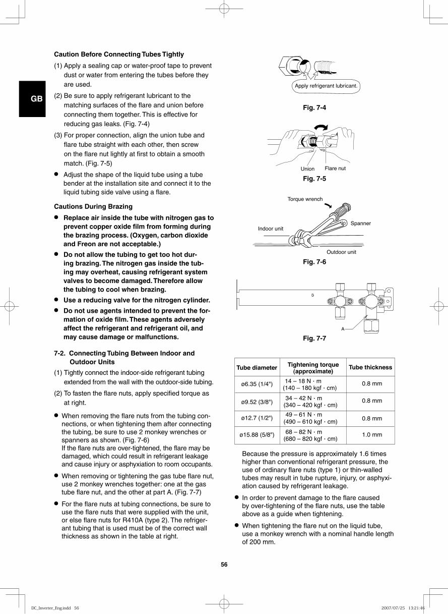
GB
FR
DE
IT
PT
GR
ES
56
Fig. 7-7
Caution Before Connecting Tubes Tightly
(1) Apply a sealing cap or water-proof tape to prevent dust or water from entering the tubes before they are used.
(2) Be sure to apply refrigerant lubricant to the matching surfaces of the flare and union before connecting them together. This is effective for reducing gas leaks. (Fig. 7-4)
(3) For proper connection, align the union tube and flare tube straight with each other, then screw on the flare nut lightly at first to obtain a smooth match. (Fig. 7-5)
● Adjust the shape of the liquid tube using a tube bender at the installation site and connect it to the liquid tubing side valve using a flare.
Cautions During Brazing
● Replace air inside the tube with nitrogen gas to prevent copper oxide film from forming during the brazing process. (Oxygen, carbon dioxide and Freon are not acceptable.)
● Do not allow the tubing to get too hot dur-ing brazing. The nitrogen gas inside the tub-ing may overheat, causing refrigerant system valves to become damaged. Therefore allow the tubing to cool when brazing.
● Use a reducing valve for the nitrogen cylinder.● Do not use agents intended to prevent the for-
mation of oxide film. These agents adversely affect the refrigerant and refrigerant oil, and may cause damage or malfunctions.
7-2. Connecting Tubing Between Indoor and Outdoor Units
(1) Tightly connect the indoor-side refrigerant tubing extended from the wall with the outdoor-side tubing.
(2) To fasten the flare nuts, apply specified torque as at right.
● When removing the flare nuts from the tubing con-nections, or when tightening them after connecting the tubing, be sure to use 2 monkey wrenches or spanners as shown. (Fig. 7-6) If the flare nuts are over-tightened, the flare may be damaged, which could result in refrigerant leakage and cause injury or asphyxiation to room occupants.
● When removing or tightening the gas tube flare nut, use 2 monkey wrenches together: one at the gas tube flare nut, and the other at part A. (Fig. 7-7)
● For the flare nuts at tubing connections, be sure to use the flare nuts that were supplied with the unit, or else flare nuts for R410A (type 2). The refriger-ant tubing that is used must be of the correct wall thickness as shown in the table at right.
Apply refrigerant lubricant.
Fig. 7-4
Flare nutUnion
Fig. 7-5
Fig. 7-6
Indoor unit
Outdoor unit
Spanner
Torque wrench
Tube diameter
ø6.35 (1/4")
ø9.52 (3/8")
ø12.7 (1/2")
ø15.88 (5/8")
Tightening torque(approximate)
14 – 18 N · m(140 – 180 kgf · cm)
34 – 42 N · m(340 – 420 kgf · cm)
49 – 61 N · m(490 – 610 kgf · cm)
68 – 82 N · m(680 – 820 kgf · cm)
0.8 mm
0.8 mm
0.8 mm
1.0 mm
Tube thickness
Because the pressure is approximately 1.6 times higher than conventional refrigerant pressure, the use of ordinary flare nuts (type 1) or thin-walled tubes may result in tube rupture, injury, or asphyxi-ation caused by refrigerant leakage.
● In order to prevent damage to the flare caused by over-tightening of the flare nuts, use the table above as a guide when tightening.
● When tightening the flare nut on the liquid tube, use a monkey wrench with a nominal handle length of 200 mm.
A
DC_Inverter_Eng.indd 56DC_Inverter_Eng.indd 56 2007/07/25 13:21:462007/07/25 13:21:46
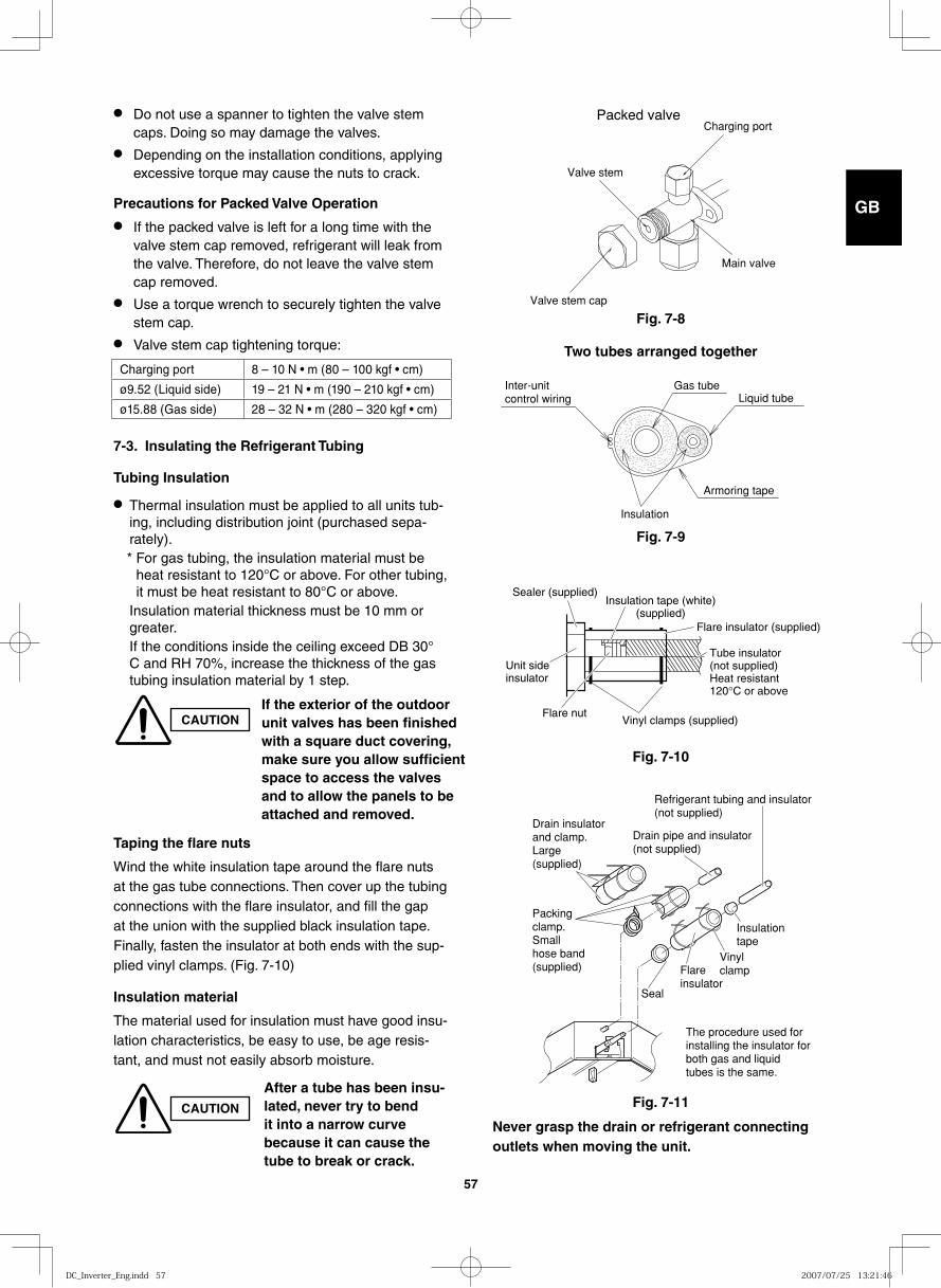
GB
FR
DE
IT
PT
GR
ES
57
Fig. 7-10
Fig. 7-9
Fig. 7-8
Fig. 7-11
● Do not use a spanner to tighten the valve stem caps. Doing so may damage the valves.
● Depending on the installation conditions, applying excessive torque may cause the nuts to crack.
Precautions for Packed Valve Operation
● If the packed valve is left for a long time with the valve stem cap removed, refrigerant will leak from the valve. Therefore, do not leave the valve stem cap removed.
● Use a torque wrench to securely tighten the valve stem cap.
● Valve stem cap tightening torque:
7-3. Insulating the Refrigerant Tubing
Tubing Insulation
● Thermal insulation must be applied to all units tub-ing, including distribution joint (purchased sepa-rately). * For gas tubing, the insulation material must be
heat resistant to 120°C or above. For other tubing, it must be heat resistant to 80°C or above.
Insulation material thickness must be 10 mm or greater.
If the conditions inside the ceiling exceed DB 30°C and RH 70%, increase the thickness of the gas tubing insulation material by 1 step.
Taping the flare nuts
Wind the white insulation tape around the flare nuts at the gas tube connections. Then cover up the tubing connections with the flare insulator, and fill the gap at the union with the supplied black insulation tape. Finally, fasten the insulator at both ends with the sup-plied vinyl clamps. (Fig. 7-10)
Insulation material
The material used for insulation must have good insu-lation characteristics, be easy to use, be age resis-tant, and must not easily absorb moisture.
After a tube has been insu-lated, never try to bend it into a narrow curve because it can cause the tube to break or crack.
CAUTIONNever grasp the drain or refrigerant connecting outlets when moving the unit.
Unit sideinsulator
Insulation tape (white)(supplied)
Sealer (supplied)
Flare insulator (supplied)
Tube insulator(not supplied)Heat resistant120°C or above
Vinyl clamps (supplied)Flare nut
The procedure used forinstalling the insulator forboth gas and liquidtubes is the same.
Seal
Flareinsulator
Vinylclamp
Insulationtape
Refrigerant tubing and insulator(not supplied)
Drain pipe and insulator(not supplied)
Drain insulatorand clamp.Large(supplied)
Packingclamp.Smallhose band(supplied)
Two tubes arranged together
CAUTIONIf the exterior of the outdoor unit valves has been finished with a square duct covering, make sure you allow sufficient space to access the valves and to allow the panels to be attached and removed.
Inter-unit control wiring
Gas tubeLiquid tube
Armoring tape
Insulation
Charging port
Valve stem cap
Valve stem
Main valve
Packed valve
Charging port 8 – 10 N • m (80 – 100 kgf • cm)
ø9.52 (Liquid side) 19 – 21 N • m (190 – 210 kgf • cm)
ø15.88 (Gas side) 28 – 32 N • m (280 – 320 kgf • cm)
DC_Inverter_Eng.indd 57DC_Inverter_Eng.indd 57 2007/07/25 13:21:462007/07/25 13:21:46
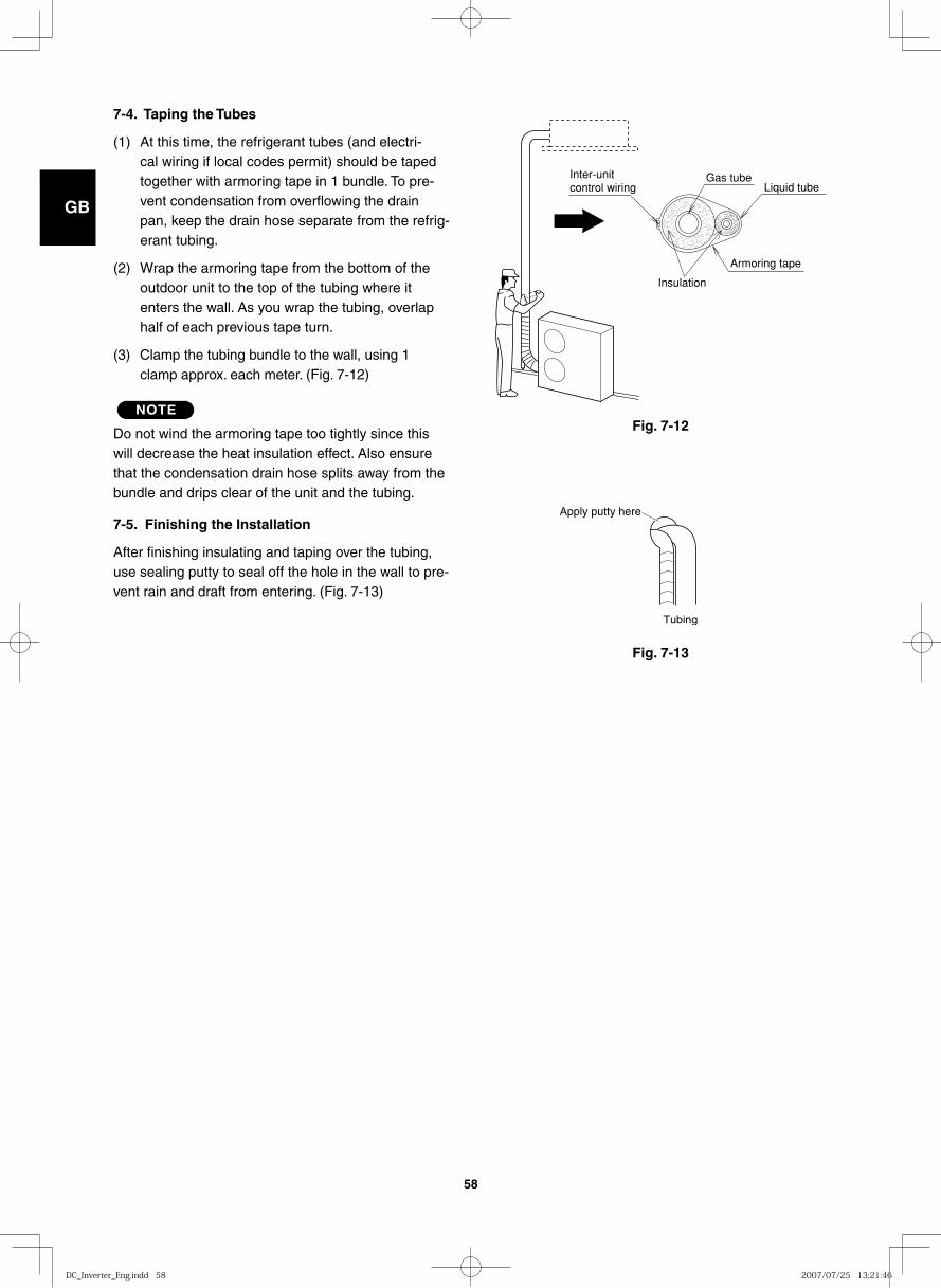
GB
FR
DE
IT
PT
GR
ES
58
Fig. 7-12
Fig. 7-13
7-4. Taping the Tubes
(1) At this time, the refrigerant tubes (and electri-cal wiring if local codes permit) should be taped together with armoring tape in 1 bundle. To pre-vent condensation from overflowing the drain pan, keep the drain hose separate from the refrig-erant tubing.
(2) Wrap the armoring tape from the bottom of the outdoor unit to the top of the tubing where it enters the wall. As you wrap the tubing, overlap half of each previous tape turn.
(3) Clamp the tubing bundle to the wall, using 1 clamp approx. each meter. (Fig. 7-12)
NOTE
Do not wind the armoring tape too tightly since this will decrease the heat insulation effect. Also ensure that the condensation drain hose splits away from the bundle and drips clear of the unit and the tubing.
7-5. Finishing the Installation
After finishing insulating and taping over the tubing, use sealing putty to seal off the hole in the wall to pre-vent rain and draft from entering. (Fig. 7-13)
Inter-unit control wiring
Gas tubeLiquid tube
Armoring tape
Insulation
Tubing
Apply putty here
DC_Inverter_Eng.indd 58DC_Inverter_Eng.indd 58 2007/07/25 13:21:462007/07/25 13:21:46
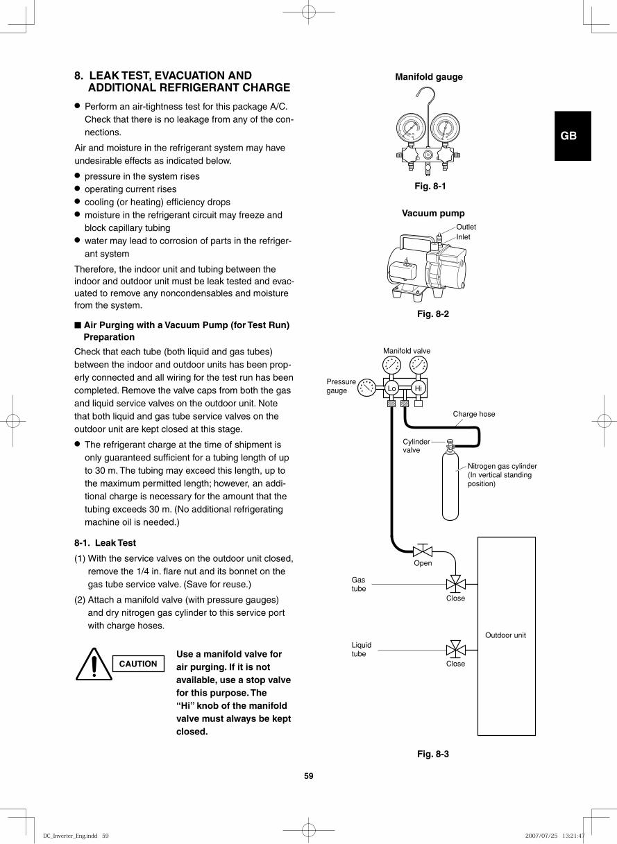
GB
FR
DE
IT
PT
GR
ES
59
Fig. 8-1
Fig. 8-2
Fig. 8-3
8. LEAK TEST, EVACUATION AND ADDITIONAL REFRIGERANT CHARGE
● Perform an air-tightness test for this package A/C. Check that there is no leakage from any of the con-nections.
Air and moisture in the refrigerant system may have undesirable effects as indicated below.
● pressure in the system rises● operating current rises● cooling (or heating) efficiency drops● moisture in the refrigerant circuit may freeze and
block capillary tubing● water may lead to corrosion of parts in the refriger-
ant system
Therefore, the indoor unit and tubing between the indoor and outdoor unit must be leak tested and evac-uated to remove any noncondensables and moisture from the system.
■ Air Purging with a Vacuum Pump (for Test Run) Preparation
Check that each tube (both liquid and gas tubes) between the indoor and outdoor units has been prop-erly connected and all wiring for the test run has been completed. Remove the valve caps from both the gas and liquid service valves on the outdoor unit. Note that both liquid and gas tube service valves on the outdoor unit are kept closed at this stage.
● The refrigerant charge at the time of shipment is only guaranteed sufficient for a tubing length of up to 30 m. The tubing may exceed this length, up to the maximum permitted length; however, an addi-tional charge is necessary for the amount that the tubing exceeds 30 m. (No additional refrigerating machine oil is needed.)
8-1. Leak Test
(1) With the service valves on the outdoor unit closed, remove the 1/4 in. flare nut and its bonnet on the gas tube service valve. (Save for reuse.)
(2) Attach a manifold valve (with pressure gauges) and dry nitrogen gas cylinder to this service port with charge hoses.
Manifold gauge
OutletInlet
Vacuum pump
Manifold valve
Pressuregauge Lo Hi
Charge hose
Outdoor unitLiquidtube
Gastube
Nitrogen gas cylinder(In vertical standingposition)
Close
Close
Open
Cylinder valve
CAUTIONUse a manifold valve for air purging. If it is not available, use a stop valve for this purpose. The “Hi” knob of the manifold valve must always be kept closed.
DC_Inverter_Eng.indd 59DC_Inverter_Eng.indd 59 2007/07/25 13:21:472007/07/25 13:21:47
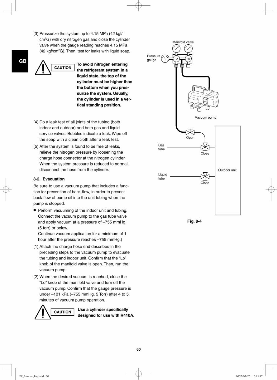
GB
FR
DE
IT
PT
GR
ES
60
Fig. 8-4
(3) Pressurize the system up to 4.15 MPa (42 kgf/cm2G) with dry nitrogen gas and close the cylinder valve when the gauge reading reaches 4.15 MPa (42 kgf/cm2G). Then, test for leaks with liquid soap.
(4) Do a leak test of all joints of the tubing (both indoor and outdoor) and both gas and liquid service valves. Bubbles indicate a leak. Wipe off the soap with a clean cloth after a leak test.
(5) After the system is found to be free of leaks, relieve the nitrogen pressure by loosening the charge hose connector at the nitrogen cylinder. When the system pressure is reduced to normal, disconnect the hose from the cylinder.
8-2. Evacuation
Be sure to use a vacuum pump that includes a func-tion for prevention of back-flow, in order to prevent back-flow of pump oil into the unit tubing when the pump is stopped.
● Perform vacuuming of the indoor unit and tubing. Connect the vacuum pump to the gas tube valve and apply vacuum at a pressure of –755 mmHg (5 torr) or below. Continue vacuum application for a minimum of 1 hour after the pressure reaches –755 mmHg.)
(1) Attach the charge hose end described in the preceding steps to the vacuum pump to evacuate the tubing and indoor unit. Confirm that the “Lo” knob of the manifold valve is open. Then, run the vacuum pump.
(2) When the desired vacuum is reached, close the “Lo” knob of the manifold valve and turn off the vacuum pump. Confirm that the gauge pressure is under –101 kPa (–755 mmHg, 5 Torr) after 4 to 5 minutes of vacuum pump operation.
Manifold valve
Pressuregauge Lo Hi
Vacuum pump
Outdoor unitLiquid tube
Gastube
Close
Close
Open
CAUTIONTo avoid nitrogen entering the refrigerant system in a liquid state, the top of the cylinder must be higher than the bottom when you pres-surize the system. Usually, the cylinder is used in a ver-tical standing position.
CAUTIONUse a cylinder specifically designed for use with R410A.
DC_Inverter_Eng.indd 60DC_Inverter_Eng.indd 60 2007/07/25 13:21:472007/07/25 13:21:47
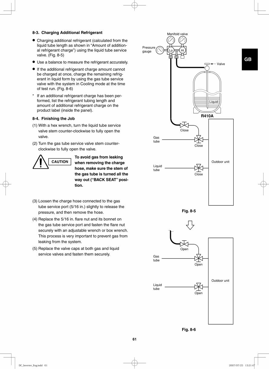
GB
FR
DE
IT
PT
GR
ES
61
Fig. 8-5
Fig. 8-6
8-3. Charging Additional Refrigerant
● Charging additional refrigerant (calculated from the liquid tube length as shown in “Amount of addition-al refrigerant charge”) using the liquid tube service valve. (Fig. 8-5)
● Use a balance to measure the refrigerant accurately.
● If the additional refrigerant charge amount cannot be charged at once, charge the remaining refrig-erant in liquid form by using the gas tube service valve with the system in Cooling mode at the time of test run. (Fig. 8-6)
* If an additional refrigerant charge has been per-formed, list the refrigerant tubing length and amount of additional refrigerant charge on the product label (inside the panel).
8-4. Finishing the Job
(1) With a hex wrench, turn the liquid tube service valve stem counter-clockwise to fully open the valve.
(2) Turn the gas tube service valve stem counter-clockwise to fully open the valve.
(3) Loosen the charge hose connected to the gas tube service port (5/16 in.) slightly to release the pressure, and then remove the hose.
(4) Replace the 5/16 in. flare nut and its bonnet on the gas tube service port and fasten the flare nut securely with an adjustable wrench or box wrench. This process is very important to prevent gas from leaking from the system.
(5) Replace the valve caps at both gas and liquid service valves and fasten them securely.
CAUTIONTo avoid gas from leaking when removing the charge hose, make sure the stem of the gas tube is turned all the way out (“BACK SEAT” posi-tion.
Valve
Liquid
Manifold valve
Pressuregauge Lo Hi
Outdoor unitLiquidtube
Gastube
Close
Close
Close
R410A
Outdoor unitLiquidtube
Gastube
Open
Open
Open
DC_Inverter_Eng.indd 61DC_Inverter_Eng.indd 61 2007/07/25 13:21:472007/07/25 13:21:47

GB
FR
DE
IT
PT
GR
ES
62
9. HOW TO INSTALL THE CEILING PANEL
■ 4-Way Air Discharge Semi-Concealed Type (X Type)
Checking the unit position
(1) Check that the ceiling hole is within this range:860 × 860 to 910 × 910 mm
(2) Use the full-scale installation diagram (from the packaging) that was supplied with the unit to determine the positioning of the unit on the ceiling surface. If the positions of the ceiling surface and unit do not match, air leakage, water leakage, flap operation failure, or other problems may result.
CAUTION
● Never place the panel face-down. Either hang it vertically or place it on top of a projecting object. Placing it face-down will damage the surface.
● Do not touch the flap or apply force to it. (This may cause flap malfunction.)
A must be within the range of 12 – 17 mm.If not within this range, malfunction or other trouble may result.
Ceiling side
Main unit
Ceiling opening dimension
A
Fig. 9-1
Wing
Fig. 9-2
Fig. 9-3
2
Fig. 9-5
9-1. Before Installing the Ceiling Panel
(1) Remove the air-intake grille and air filter from the ceiling panel. (Figs. 9-3, 9-4 and 9-5)
a) Remove the 2 screws on the latch of the air-intake grille. (Fig. 9-3)
b) Slide the air-intake grille catches in the direction shown by the arrows 1 to open the grille. (Fig. 9-4)
c) With the air-intake grille opened, remove the grille hinge from the ceiling panel by sliding it in the direction shown by the arrow 2. (Fig. 9-5)
(2) Removing the corner cover
a) Slide the corner cover to the direction shown by the arrow 1 to remove the corner cover. (Fig. 9-6)
Corner cover
Ceiling panel
Strap
Push
1
Corner cover
Fig. 9-6
Air-intake grille Ceiling panel
Air-intake grille hinge
11
Fig. 9-4
LatchScrew
DC_Inverter_Eng.indd 62DC_Inverter_Eng.indd 62 2007/07/25 13:21:472007/07/25 13:21:47
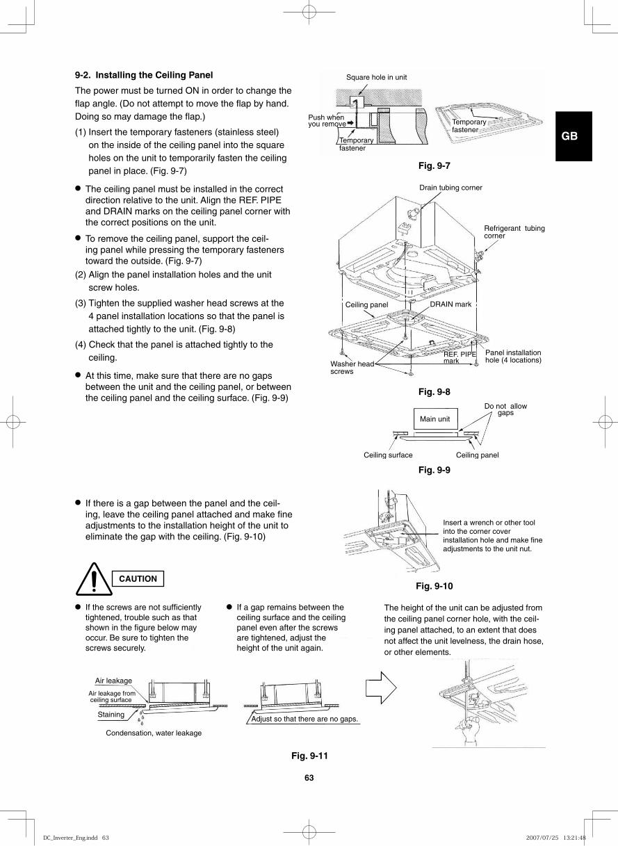
GB
FR
DE
IT
PT
GR
ES
63
CAUTION
9-2. Installing the Ceiling Panel
The power must be turned ON in order to change the flap angle. (Do not attempt to move the flap by hand. Doing so may damage the flap.)
(1) Insert the temporary fasteners (stainless steel) on the inside of the ceiling panel into the square holes on the unit to temporarily fasten the ceiling panel in place. (Fig. 9-7)
● The ceiling panel must be installed in the correct direction relative to the unit. Align the REF. PIPE and DRAIN marks on the ceiling panel corner with the correct positions on the unit.
● To remove the ceiling panel, support the ceil-ing panel while pressing the temporary fasteners toward the outside. (Fig. 9-7)
(2) Align the panel installation holes and the unit screw holes.
(3) Tighten the supplied washer head screws at the 4 panel installation locations so that the panel is attached tightly to the unit. (Fig. 9-8)
(4) Check that the panel is attached tightly to the ceiling.
● At this time, make sure that there are no gaps between the unit and the ceiling panel, or between the ceiling panel and the ceiling surface. (Fig. 9-9)
Square hole in unit
Temporary fastener
Push when you remove Temporary
fastener
Fig. 9-7
Drain tubing corner
Refrigerant tubing corner
Panel installation hole (4 locations)
Ceiling panel
Washer head screws
DRAIN mark
REF. PIPE mark
Fig. 9-8Do not allow
gaps
Ceiling panel
Main unit
Ceiling surface
Fig. 9-9
Insert a wrench or other tool into the corner cover installation hole and make fine adjustments to the unit nut.
Air leakage
Air leakage from ceiling surface
Staining
Condensation, water leakage
Adjust so that there are no gaps.
Fig. 9-10
Fig. 9-11
● If there is a gap between the panel and the ceil-ing, leave the ceiling panel attached and make fine adjustments to the installation height of the unit to eliminate the gap with the ceiling. (Fig. 9-10)
● If the screws are not sufficiently tightened, trouble such as that shown in the figure below may occur. Be sure to tighten the screws securely.
● If a gap remains between the ceiling surface and the ceiling panel even after the screws are tightened, adjust the height of the unit again.
The height of the unit can be adjusted from the ceiling panel corner hole, with the ceil-ing panel attached, to an extent that does not affect the unit levelness, the drain hose, or other elements.
DC_Inverter_Eng.indd 63DC_Inverter_Eng.indd 63 2007/07/25 13:21:482007/07/25 13:21:48
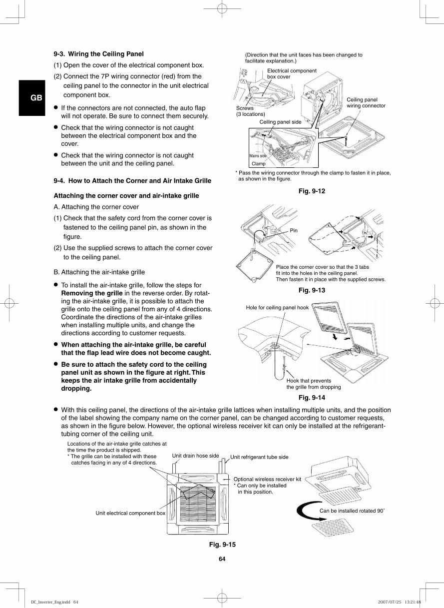
GB
FR
DE
IT
PT
GR
ES
64
9-3. Wiring the Ceiling Panel
(1) Open the cover of the electrical component box.
(2) Connect the 7P wiring connector (red) from the ceiling panel to the connector in the unit electrical component box.
● If the connectors are not connected, the auto flap will not operate. Be sure to connect them securely.
● Check that the wiring connector is not caught between the electrical component box and the cover.
● Check that the wiring connector is not caught between the unit and the ceiling panel.
9-4. How to Attach the Corner and Air Intake Grille
Attaching the corner cover and air-intake grille
A. Attaching the corner cover
(1) Check that the safety cord from the corner cover is fastened to the ceiling panel pin, as shown in the figure.
(2) Use the supplied screws to attach the corner cover to the ceiling panel.
B. Attaching the air-intake grille
● To install the air-intake grille, follow the steps for Removing the grille in the reverse order. By rotat-ing the air-intake grille, it is possible to attach the grille onto the ceiling panel from any of 4 directions. Coordinate the directions of the air-intake grilles when installing multiple units, and change the directions according to customer requests.
● When attaching the air-intake grille, be careful that the flap lead wire does not become caught.
● Be sure to attach the safety cord to the ceiling panel unit as shown in the figure at right. This keeps the air intake grille from accidentally dropping.
(Direction that the unit faces has been changed to facilitate explanation.)
Ceiling panel wiring connector
Ceiling panel side
Screws(3 locations)
Mains side
Clamp
Electrical component box cover
* Pass the wiring connector through the clamp to fasten it in place, as shown in the figure.
Place the corner cover so that the 3 tabsfit into the holes in the ceiling panel. Then fasten it in place with the supplied screws.
Pin
● With this ceiling panel, the directions of the air-intake grille lattices when installing multiple units, and the position of the label showing the company name on the corner panel, can be changed according to customer requests, as shown in the figure below. However, the optional wireless receiver kit can only be installed at the refrigerant-tubing corner of the ceiling unit.
Unit electrical component box
Unit drain hose side Unit refrigerant tube side
Optional wireless receiver kit* Can only be installed in this position.
Can be installed rotated 90˚
Locations of the air-intake grille catches at the time the product is shipped.* The grille can be installed with these
catches facing in any of 4 directions.
Fig. 9-12
Fig. 9-13
Hole for ceiling panel hook
Hook that prevents the grille from dropping
Fig. 9-14
Fig. 9-15
DC_Inverter_Eng.indd 64DC_Inverter_Eng.indd 64 2007/07/25 13:21:482007/07/25 13:21:48
GB
FR
DE
IT
PT
GR
ES
65
9-5. Checking After Installation
● Check that there are no gaps between the unit and the ceiling panel, or between the ceiling panel and the ceiling surface. Gaps may cause water leakage and condensation.
● Check that the wiring is securely connected. If it is not securely connected, the auto flap will not operate. (“P09” is displayed on the remote control-ler.) In addition, water leakage and condensation may occur.
9-6. When Removing the Ceiling Panel for Servicing
When removing the ceiling panel for servicing, remove the air-intake grille and air filter, disconnect the wiring connector inside the electrical component box, and then remove the 4 mounting screws.
9-7. Adjusting the Auto Flap
The air-direction louver on the ceiling panel outlet can be adjusted as follows.
● Adjust the louver to the desired angle using the remote controller. The louver also has an automatic air-sweeping mechanism.
NOTE
● Never attempt to move the louver by hand.
● Proper air flow depends on the location of the air conditioner, the layout of the room and furniture, etc. If cooling or heating seems inadequate, try changing the direction of the air flow.
DC_Inverter_Eng.indd 65DC_Inverter_Eng.indd 65 2007/07/25 13:21:482007/07/25 13:21:48
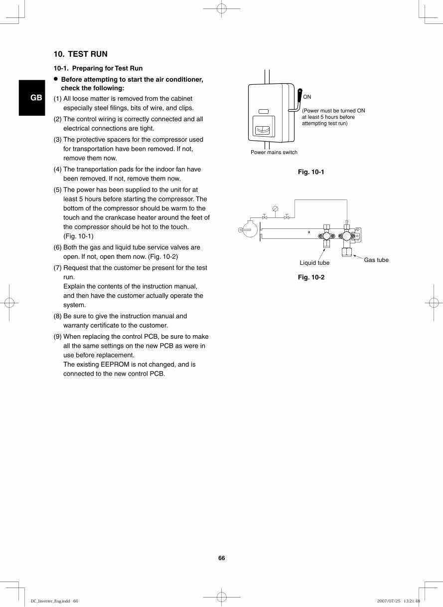
GB
FR
DE
IT
PT
GR
ES
66
10. TEST RUN
10-1. Preparing for Test Run
● Before attempting to start the air conditioner, check the following:
(1) All loose matter is removed from the cabinet especially steel filings, bits of wire, and clips.
(2) The control wiring is correctly connected and all electrical connections are tight.
(3) The protective spacers for the compressor used for transportation have been removed. If not, remove them now.
(4) The transportation pads for the indoor fan have been removed. If not, remove them now.
(5) The power has been supplied to the unit for at least 5 hours before starting the compressor. The bottom of the compressor should be warm to the touch and the crankcase heater around the feet of the compressor should be hot to the touch. (Fig. 10-1)
(6) Both the gas and liquid tube service valves are open. If not, open them now. (Fig. 10-2)
(7) Request that the customer be present for the test run.Explain the contents of the instruction manual, and then have the customer actually operate the system.
(8) Be sure to give the instruction manual and warranty certificate to the customer.
(9) When replacing the control PCB, be sure to make all the same settings on the new PCB as were in use before replacement. The existing EEPROM is not changed, and is connected to the new control PCB.
Fig. 10-1
Fig. 10-2
Power mains switch
(Power must be turned ONat least 5 hours beforeattempting test run)
ON
Liquid tube Gas tube
DC_Inverter_Eng.indd 66DC_Inverter_Eng.indd 66 2007/07/25 13:21:482007/07/25 13:21:48
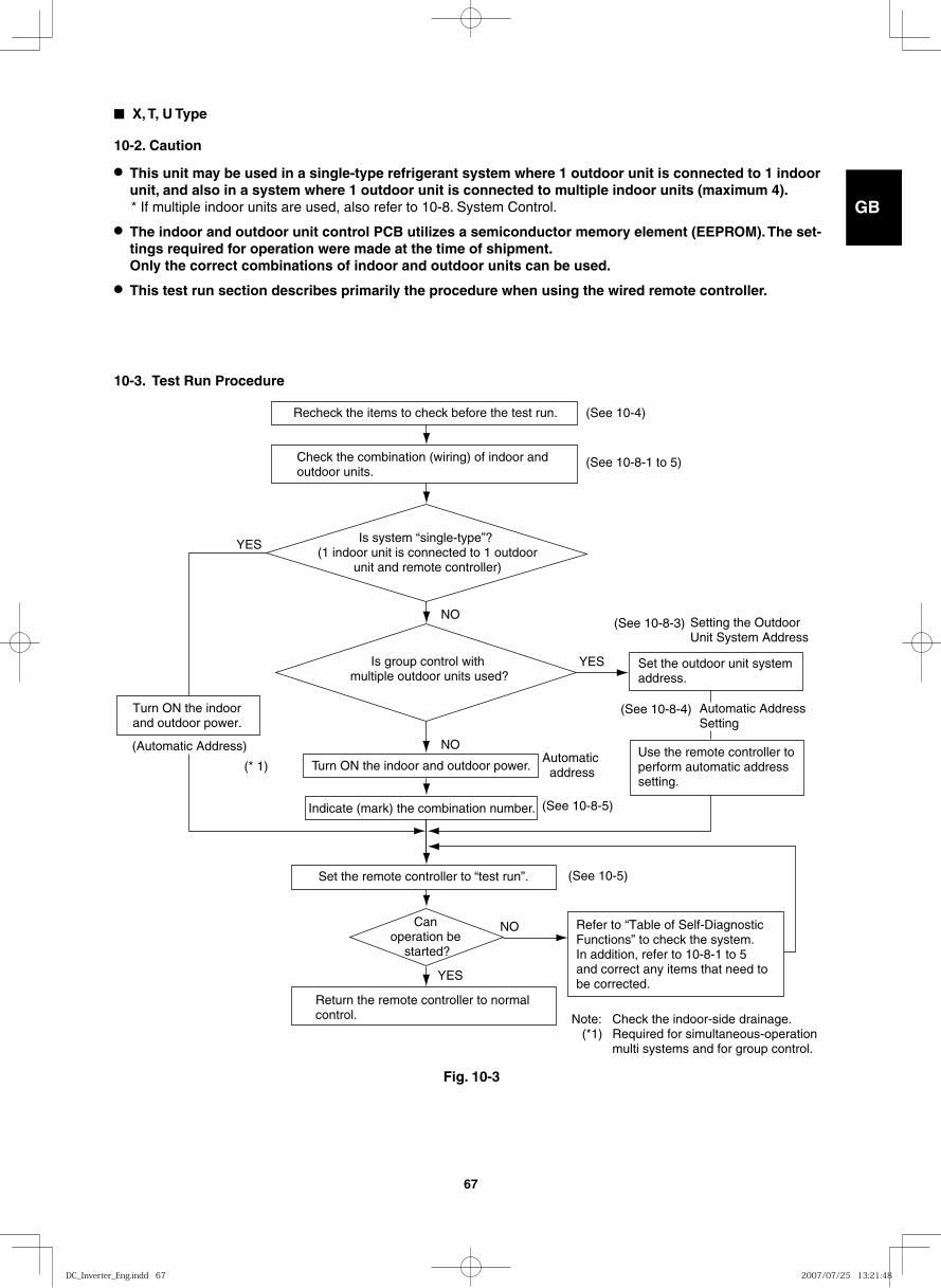
GB
FR
DE
IT
PT
GR
ES
67
■ X, T, U Type
10-2. Caution
● This unit may be used in a single-type refrigerant system where 1 outdoor unit is connected to 1 indoor unit, and also in a system where 1 outdoor unit is connected to multiple indoor units (maximum 4). * If multiple indoor units are used, also refer to 10-8. System Control.
● The indoor and outdoor unit control PCB utilizes a semiconductor memory element (EEPROM). The set-tings required for operation were made at the time of shipment. Only the correct combinations of indoor and outdoor units can be used.
● This test run section describes primarily the procedure when using the wired remote controller.
10-3. Test Run Procedure
Recheck the items to check before the test run.
Indicate (mark) the combination number.
Turn ON the indoor and outdoor power.
Set the remote controller to “test run”.
Turn ON the indoor and outdoor power.
Return the remote controller to normal control.
YES
YES
YES
NO
NO
NO
Automatic address
(See 10-4)
(See 10-8-1 to 5)
(See 10-8-3)
(See 10-8-4)
(See 10-8-5)
(See 10-5)
(* 1)
Check the combination (wiring) of indoor and outdoor units.
Is system “single-type”? (1 indoor unit is connected to 1 outdoor
unit and remote controller)
Is group control with multiple outdoor units used?
Can operation be
started?
Setting the Outdoor Unit System Address
Automatic Address Setting
Set the outdoor unit system address.
Use the remote controller to perform automatic address setting.
Refer to “Table of Self-Diagnostic Functions” to check the system. In addition, refer to 10-8-1 to 5and correct any items that need to be corrected.
Note: Check the indoor-side drainage. (*1) Required for simultaneous-operation multi systems and for group control.
(Automatic Address)
Fig. 10-3
DC_Inverter_Eng.indd 67DC_Inverter_Eng.indd 67 2007/07/25 13:21:482007/07/25 13:21:48
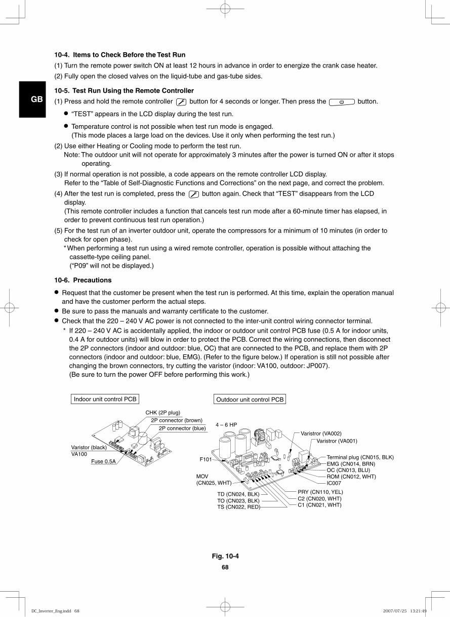
GB
FR
DE
IT
PT
GR
ES
68
10-4. Items to Check Before the Test Run
(1) Turn the remote power switch ON at least 12 hours in advance in order to energize the crank case heater.
(2) Fully open the closed valves on the liquid-tube and gas-tube sides.
10-5. Test Run Using the Remote Controller
(1) Press and hold the remote controller button for 4 seconds or longer. Then press the button.
● “TEST” appears in the LCD display during the test run.
● Temperature control is not possible when test run mode is engaged. (This mode places a large load on the devices. Use it only when performing the test run.)
(2) Use either Heating or Cooling mode to perform the test run.Note: The outdoor unit will not operate for approximately 3 minutes after the power is turned ON or after it stops
operating.
(3) If normal operation is not possible, a code appears on the remote controller LCD display. Refer to the “Table of Self-Diagnostic Functions and Corrections” on the next page, and correct the problem.
(4) After the test run is completed, press the button again. Check that “TEST” disappears from the LCD display. (This remote controller includes a function that cancels test run mode after a 60-minute timer has elapsed, in order to prevent continuous test run operation.)
(5) For the test run of an inverter outdoor unit, operate the compressors for a minimum of 10 minutes (in order to check for open phase).* When performing a test run using a wired remote controller, operation is possible without attaching the
cassette-type ceiling panel. (“P09” will not be displayed.)
10-6. Precautions
● Request that the customer be present when the test run is performed. At this time, explain the operation manual and have the customer perform the actual steps.
● Be sure to pass the manuals and warranty certificate to the customer.● Check that the 220 – 240 V AC power is not connected to the inter-unit control wiring connector terminal.
* If 220 – 240 V AC is accidentally applied, the indoor or outdoor unit control PCB fuse (0.5 A for indoor units, 0.4 A for outdoor units) will blow in order to protect the PCB. Correct the wiring connections, then disconnect the 2P connectors (indoor and outdoor: blue, OC) that are connected to the PCB, and replace them with 2P connectors (indoor and outdoor: blue, EMG). (Refer to the figure below.) If operation is still not possible after changing the brown connectors, try cutting the varistor (indoor: VA100, outdoor: JP007). (Be sure to turn the power OFF before performing this work.)
Indoor unit control PCB Outdoor unit control PCB
Varistor (black)
Fuse 0.5A VA100
2P connector (brown)
2P connector (blue)
CHK (2P plug)
4 – 6 HP
Varistror (VA002)Varistror (VA001)
F101
TO (CN023, BLK)TS (CN022, RED)
TD (CN024, BLK)
C1 (CN021, WHT)C2 (CN020, WHT)PRY (CN110, YEL)
OC (CN013, BLU)ROM (CN012, WHT)IC007
EMG (CN014, BRN)Terminal plug (CN015, BLK)
MOV(CN025, WHT)
Fig. 10-4
DC_Inverter_Eng.indd 68DC_Inverter_Eng.indd 68 2007/07/25 13:21:492007/07/25 13:21:49
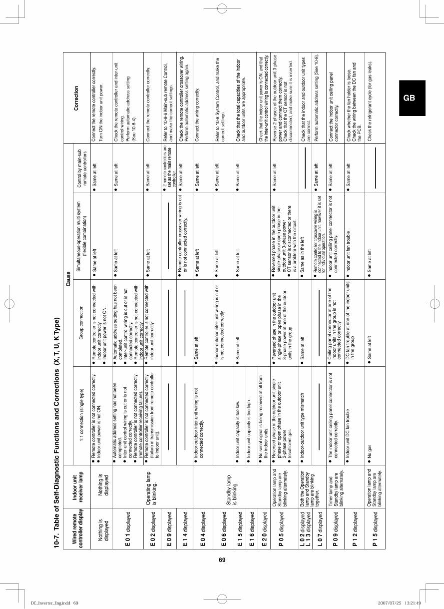
GB
FR
DE
IT
PT
GR
ES
69
Wir
ed r
emot
e co
ntro
ller
disp
lay
Cau
se
Cor
rect
ion
Not
hing
is
disp
laye
dN
othi
ng is
di
spla
yed
E 0
1 d
ispl
ayed
E 0
2 d
ispl
ayed
E 0
9 d
ispl
ayed
E 1
4 d
ispl
ayed
E 0
4 d
ispl
ayed
E 0
6 d
ispl
ayed
E 1
5 d
ispl
ayed
E 1
6 d
ispl
ayed
E 2
0 d
ispl
ayed
P 0
5 d
ispl
ayed
L 0
2 di
spla
yed
L 1
3 di
spla
yed
P 0
9 d
ispl
ayed
L 0
7 di
spla
yed
P 1
2 d
ispl
ayed
P 1
5 d
ispl
ayed
Indo
or u
nit
rece
iver
lam
p
Ope
ratin
g la
mp
is b
linki
ng.
Sta
ndby
lam
pis
blin
king
.
Bot
h th
e O
pera
tion
lam
p an
d S
tand
by
lam
p ar
e bl
inki
ng
toge
ther
.
Ope
ratio
n la
mp
and
Sta
ndby
lam
p ar
e bl
inki
ng a
ltern
atel
y.
Ope
ratio
n la
mp
and
Sta
ndby
lam
p ar
e bl
inki
ng a
ltern
atel
y.
Tim
er la
mp
and
Sta
ndby
lam
p ar
e bl
inki
ng a
ltern
atel
y.
● R
emot
e co
ntro
ller i
s no
t con
nect
ed c
orre
ctly.
● I
ndoo
r uni
t pow
er is
not
ON
.
● A
utom
atic
add
ress
set
ting
has
not b
een
com
plet
ed.
● I
nter
-uni
t con
trol w
iring
is c
ut o
r is
not
conn
ecte
d co
rrec
tly.
● R
emot
e co
ntro
ller i
s no
t con
nect
ed c
orre
ctly
(r
emot
e co
ntro
ller r
ecei
ving
failu
re).
● R
emot
e co
ntro
ller i
s no
t con
nect
ed c
orre
ctly
(fa
ilure
in tr
ansm
issi
on fr
om re
mot
e co
ntro
ller
to in
door
uni
t).
● I
ndoo
r-ou
tdoo
r int
er-u
nit w
iring
is n
ot
conn
ecte
d co
rrec
tly.
● I
ndoo
r uni
t cap
acity
is to
o lo
w.
● I
ndoo
r uni
t cap
acity
is to
o hi
gh.
● N
o se
rial s
igna
l is
bein
g re
ceiv
ed a
t all
from
th
e in
door
uni
ts.
● R
ever
sed
phas
e in
the
outd
oor u
nit s
ingl
e-
phas
e or
ope
n ph
ase
in th
e ou
tdoo
r uni
t 3-
phas
e po
wer
● I
nsuf
ficie
nt g
as
● I
ndoo
r-ou
tdoo
r uni
t typ
e m
ism
atch
● T
he in
door
uni
t cei
ling
pane
l con
nect
or is
not
co
nnec
ted
corr
ectly
.
● I
ndoo
r uni
t DC
fan
troub
le
● R
emot
e co
ntro
ller i
s no
t con
nect
ed w
ith
indo
or u
nit c
orre
ctly
● I
ndoo
r uni
t pow
er is
not
ON
.
● A
utom
atic
add
ress
set
ting
has
not b
een
com
plet
ed.
● I
nter
-uni
t con
trol w
iring
is c
ut o
r is
not
conn
ecte
d co
rrec
tly.
● R
emot
e co
ntro
ller i
s no
t con
nect
ed w
ith
indo
or u
nit c
orre
ctly
● R
emot
e co
ntro
ller i
s no
t con
nect
ed w
ith
indo
or u
nit c
orre
ctly
● S
ame
at le
ft
● I
ndoo
r-ou
tdoo
r int
er-u
nit w
iring
is c
ut o
r is
not
con
nect
ed c
orre
ctly.
● S
ame
at le
ft
● R
ever
sed
phas
e in
the
outd
oor u
nit
sing
le p
hase
or o
pen
phas
e in
the
3-ph
ase
pow
er a
t one
of t
he o
utdo
or
units
in th
e gr
oup
● S
ame
at le
ft
● S
ame
at le
ft● S
ame
at le
ft
Sim
ulta
neou
s-op
erat
ion
mul
ti sy
stem
(fl
exib
le c
ombi
natio
n)
● S
ame
at le
ft● S
ame
at le
ft
● S
ame
at le
ft● S
ame
at le
ft
● S
ame
at le
ft
● S
ame
at le
ft
● S
ame
at le
ft
● S
ame
at le
ft
● S
ame
at le
ft
● S
ame
as in
the
left
● S
ame
at le
ft
● S
ame
at le
ft
● S
ame
at le
ft
● S
ame
at le
ft
● S
ame
at le
ft
● S
ame
at le
ft
● R
emot
e co
ntro
ller c
ross
over
wiri
ng is
cut
or
is n
ot c
onne
cted
cor
rect
ly.
● I
ndoo
r uni
t cei
ling
pane
l con
nect
or is
not
co
nnec
ted
corr
ectly
.
● I
ndoo
r uni
t fan
trou
ble
● R
emot
e co
ntro
ller c
ross
over
wiri
ng is
co
nnec
ted
to th
e in
door
uni
t, ho
wev
er it
is s
et
for i
ndiv
idua
l ope
ratio
n.
Con
nect
the
rem
ote
cont
rolle
r cor
rect
ly.
Turn
ON
the
indo
or u
nit p
ower
.
● 2
rem
ote
cont
rolle
rs a
re
set a
s th
e m
ain
rem
ote
cont
rolle
r.
Con
trol b
y m
ain-
sub
rem
ote
cont
rolle
rs
Che
ck th
e re
mot
e co
ntro
ller a
nd in
ter-
unit
cont
rol w
iring
.Pe
rform
aut
omat
ic a
ddre
ss s
ettin
g (S
ee 1
0-8-
4).
Con
nect
the
rem
ote
cont
rolle
r cor
rect
ly.
Ref
er to
10-
8-6
Mai
n-su
b re
mot
e C
ontro
l, an
d m
ake
the
corr
ect s
ettin
gs.
Che
ck th
e re
mot
e co
ntro
ller c
ross
over
wiri
ng.
Perfo
rm a
utom
atic
add
ress
set
ting
agai
n.
Con
nect
the
wiri
ng c
orre
ctly.
Ref
er to
10-
8 S
yste
m C
ontro
l, an
d m
ake
the
corr
ect s
ettin
gs.
Che
ck th
at th
e to
tal c
apac
ities
of t
he in
door
an
d ou
tdoo
r uni
ts a
re a
ppro
pria
te.
Che
ck w
heth
er th
e fa
n ho
lder
is lo
ose.
Che
ck th
e w
iring
bet
wee
n th
e D
C fa
n an
d th
e P
CB
.
Che
ck th
at th
e in
door
uni
t pow
er is
ON
, and
that
th
e in
ter-u
nit c
ontro
l wiri
ng is
con
nect
ed c
orre
ctly.
Rev
erse
2 p
hase
s of
the
outd
oor u
nit 3
-pha
se
pow
er a
nd c
onne
ct th
em c
orre
ctly.
Che
ck th
at th
e C
T se
nsor
is n
ot
disc
onne
cted
, and
mak
e su
re it
is in
sert
ed.
Che
ck th
at th
e in
door
and
out
door
uni
t typ
es
are
corr
ect.
Perfo
rm a
utom
atic
add
ress
set
ting
(See
10-
8).
Con
nect
the
indo
or u
nit c
eilin
g pa
nel
conn
ecto
r cor
rect
ly.
● D
C fa
n tr
oubl
e at
one
of t
he in
door
uni
ts
in th
e gr
oup
● C
eilin
g pa
nel c
onne
ctor
at o
ne o
f the
in
door
uni
ts in
the
grou
p is
not
co
nnec
ted
corr
ectly
.
Gro
up c
onne
ctio
n
● R
ever
sed
phas
e in
the
outd
oor u
nit
sing
le-p
hase
or o
pen
phas
e in
the
outd
oor u
nit 3
-pha
se p
ower
● C
T se
nsor
is d
isco
nnec
ted
or th
ere
is a
pro
blem
with
the
circ
uit.
1:1
conn
ectio
n (s
ingl
e ty
pe)
● N
o ga
s● S
ame
at le
ft● S
ame
at le
ftC
heck
the
refr
iger
ant c
ycle
(for
gas
leak
s).
10-7
. Ta
ble
of
Sel
f-D
iag
no
stic
Fu
nct
ion
s an
d C
orr
ecti
on
s (
X, T
, U, K
Typ
e)
DC_Inverter_Eng.indd 69DC_Inverter_Eng.indd 69 2007/07/25 13:21:492007/07/25 13:21:49
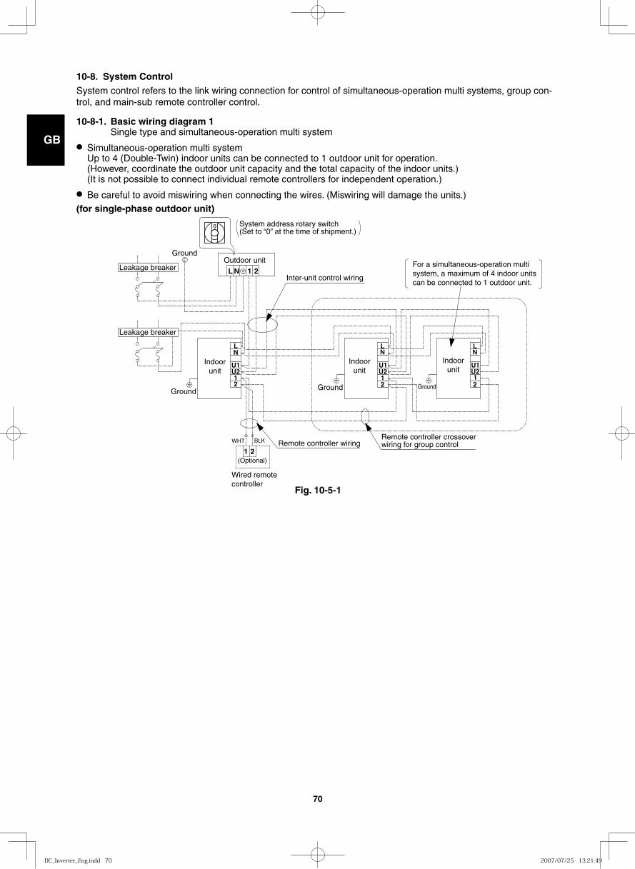
GB
FR
DE
IT
PT
GR
ES
70
10-8. System Control System control refers to the link wiring connection for control of simultaneous-operation multi systems, group con-trol, and main-sub remote controller control.
10-8-1. Basic wiring diagram 1 Single type and simultaneous-operation multi system
● Simultaneous-operation multi system Up to 4 (Double-Twin) indoor units can be connected to 1 outdoor unit for operation. (However, coordinate the outdoor unit capacity and the total capacity of the indoor units.) (It is not possible to connect individual remote controllers for independent operation.)
● Be careful to avoid miswiring when connecting the wires. (Miswiring will damage the units.)
1 2
1 2
1 2
U2 U1
L N
N
U1 U2 1 2
L
L N
1 2
U2 U1
L N
Remote controller crossover wiring for group control
System address rotary switch (Set to “0” at the time of shipment.)
Inter-unit control wiring
Outdoor unit
Indoor unit
Indoor unit
Indoor unit
For a simultaneous-operation multi system, a maximum of 4 indoor units can be connected to 1 outdoor unit.
Ground
Wired remote controller
Remote controller wiring WHT BLK
(Optional)
Ground
Ground Ground
Leakage breaker
Leakage breaker
(for single-phase outdoor unit)
Fig. 10-5-1
DC_Inverter_Eng.indd 70DC_Inverter_Eng.indd 70 2007/07/25 13:21:492007/07/25 13:21:49
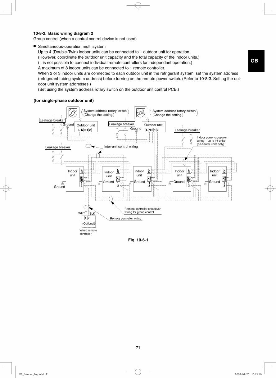
GB
FR
DE
IT
PT
GR
ES
71
10-8-2. Basic wiring diagram 2 Group control (when a central control device is not used)
● Simultaneous-operation multi system Up to 4 (Double-Twin) indoor units can be connected to 1 outdoor unit for operation. (However, coordinate the outdoor unit capacity and the total capacity of the indoor units.) (It is not possible to connect individual remote controllers for independent operation.) A maximum of 8 indoor units can be connected to 1 remote controller.When 2 or 3 indoor units are connected to each outdoor unit in the refrigerant system, set the system address (refrigerant tubing system address) before turning on the remote power switch. (Refer to 10-8-3. Setting the out-door unit system addresses.) (Set using the system address rotary switch on the outdoor unit control PCB.)
Fig. 10-6-1
1 2
1 2
12
U2U1
12
U2U1
12
U2U1
1 2
LN
LN
LN
TNL NL
12
U2U1
LN
LN
12
U2U1
Outdoor unit
Indoor unit
Indoor unit
Indoor unit
Indoor unit
Indoor unit
Outdoor unitGroundGround
Ground
Ground Ground Ground Ground
(Optional)
Wired remote controller
Remote controller wiring
Remote controller crossover wiring for group control
System address rotary switch (Change the setting.)
System address rotary switch (Change the setting.)
Indoor power crossover wiring – up to 16 units (no-heater units only)
Inter-unit control wiring
WHT BLK
Leakage breaker
Leakage breaker
Leakage breaker
Leakage breaker
(for single-phase outdoor unit)
DC_Inverter_Eng.indd 71DC_Inverter_Eng.indd 71 2007/07/25 13:21:492007/07/25 13:21:49
GB
FR
DE
IT
PT
GR
ES
72
(Wiring procedure)
(1) Connect the remote controller to the indoor unit remote controller wiring terminal plate (1, 2). (Remote controller wiring)
(2) Connect the indoor units (U1, U2) and the outdoor units (1, 2). Connect the other outdoor units and indoor units (with different refrigerant systems) in the same way. (Inter-unit control wiring) Connect the remote controller crossover wiring to the indoor units (U1, U2) for each refrigerant system. (Inter-unit control wiring)
(3) Connect the remote controller crossover wiring (2 wires) from the remote controller wiring terminal plate (1, 2) on the indoor unit (unit where the remote controller is connected) to the remote controller terminal plates (1, 2) on the other indoor units. (Remote controller crossover wiring)
(4) Turn ON both the indoor and outdoor unit power and perform automatic address setting from the remote controller. (For the automatic address setting procedure, refer to 10-8-4.)
NOTE
* Models with auxiliary heaters cannot be used for crossover wiring of the indoor unit power wires. (Use a pull box to divide the wiring.) Be sure to use the indoor unit temperature sensor (body sensor) when using this control. (Status at shipment.)
DC_Inverter_Eng.indd 72DC_Inverter_Eng.indd 72 2007/07/25 13:21:492007/07/25 13:21:49
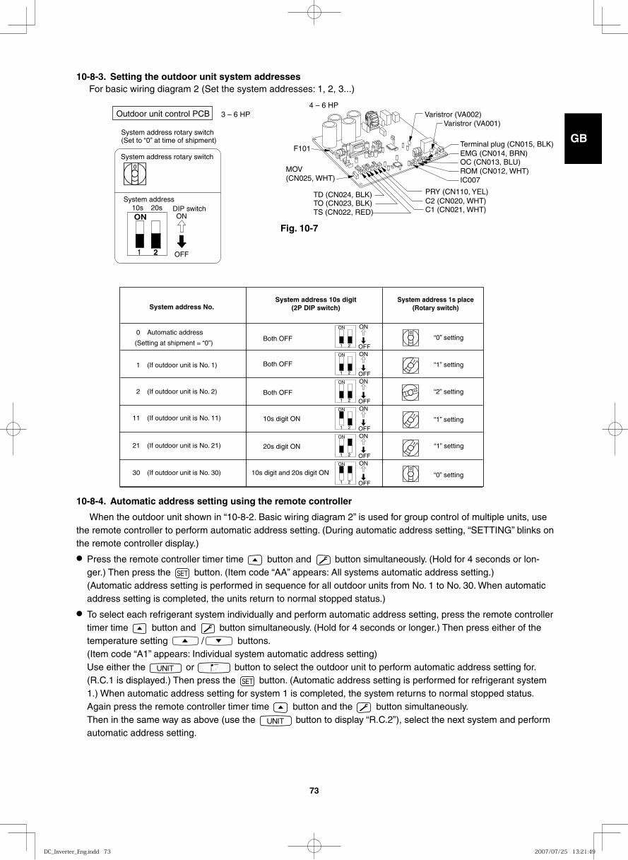
GB
FR
DE
IT
PT
GR
ES
73
10-8-3. Setting the outdoor unit system addresses For basic wiring diagram 2 (Set the system addresses: 1, 2, 3...)
ON
1 2
System address rotary switch(Set to “0” at time of shipment)
System address rotary switch
System addressDIP switch
OFF
ON10s 20s
3 – 6 HPOutdoor unit control PCB
System address No. System address 10s digit
(2P DIP switch) System address 1s place
(Rotary switch)
0 Automatic address
(Setting at shipment = “0”)
1 (If outdoor unit is No. 1)
“0” setting Both OFF
Both OFF
Both OFF
10s digit ON
20s digit ON
10s digit and 20s digit ON
“1” setting
“2” setting
“1” setting
“1” setting
“0” setting
2 (If outdoor unit is No. 2)
11 (If outdoor unit is No. 11)
21 (If outdoor unit is No. 21)
30 (If outdoor unit is No. 30)
ON ON
OFF 1 2
ON ON
OFF 1 2
ON ON
OFF 1 2
ON ON
OFF 1 2
ON ON
OFF 1 2
ON ON
OFF 1 2
10-8-4. Automatic address setting using the remote controller
When the outdoor unit shown in “10-8-2. Basic wiring diagram 2” is used for group control of multiple units, use the remote controller to perform automatic address setting. (During automatic address setting, “SETTING” blinks on the remote controller display.)
● Press the remote controller timer time button and button simultaneously. (Hold for 4 seconds or lon-ger.) Then press the button. (Item code “AA” appears: All systems automatic address setting.)(Automatic address setting is performed in sequence for all outdoor units from No. 1 to No. 30. When automatic address setting is completed, the units return to normal stopped status.)
● To select each refrigerant system individually and perform automatic address setting, press the remote controller timer time button and button simultaneously. (Hold for 4 seconds or longer.) Then press either of the temperature setting / buttons. (Item code “A1” appears: Individual system automatic address setting) Use either the or button to select the outdoor unit to perform automatic address setting for. (R.C.1 is displayed.) Then press the button. (Automatic address setting is performed for refrigerant system 1.) When automatic address setting for system 1 is completed, the system returns to normal stopped status. Again press the remote controller timer time button and the button simultaneously. Then in the same way as above (use the button to display “R.C.2”), select the next system and perform automatic address setting.
4 – 6 HPVaristror (VA002)
Varistror (VA001)
C1 (CN021, WHT)C2 (CN020, WHT)PRY (CN110, YEL)
OC (CN013, BLU)ROM (CN012, WHT)IC007
EMG (CN014, BRN)Terminal plug (CN015, BLK)
F101
TO (CN023, BLK)TS (CN022, RED)
TD (CN024, BLK)
MOV(CN025, WHT)
Fig. 10-7
DC_Inverter_Eng.indd 73DC_Inverter_Eng.indd 73 2007/07/25 13:21:492007/07/25 13:21:49
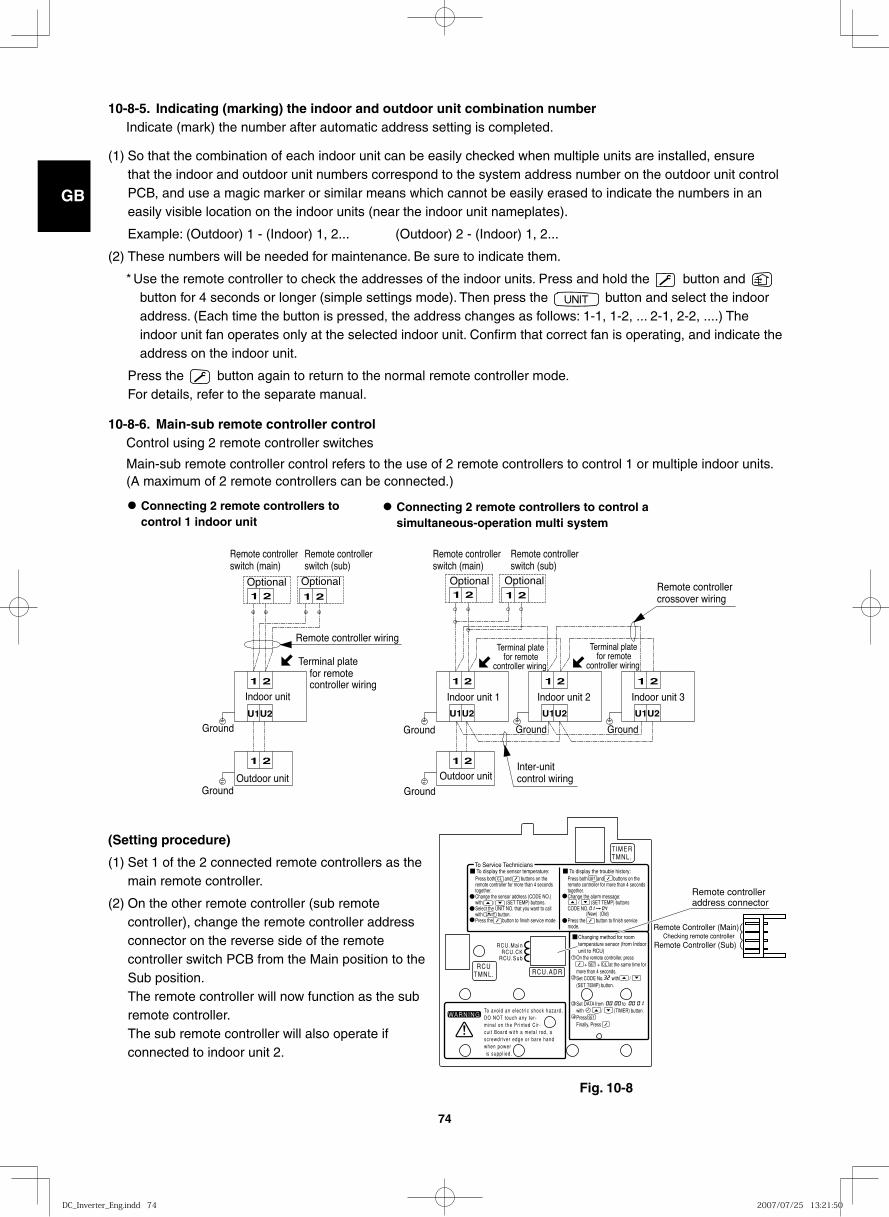
GB
FR
DE
IT
PT
GR
ES
74
10-8-5. Indicating (marking) the indoor and outdoor unit combination number Indicate (mark) the number after automatic address setting is completed.
(1) So that the combination of each indoor unit can be easily checked when multiple units are installed, ensure that the indoor and outdoor unit numbers correspond to the system address number on the outdoor unit control PCB, and use a magic marker or similar means which cannot be easily erased to indicate the numbers in an easily visible location on the indoor units (near the indoor unit nameplates).
Example: (Outdoor) 1 - (Indoor) 1, 2... (Outdoor) 2 - (Indoor) 1, 2...
(2) These numbers will be needed for maintenance. Be sure to indicate them.
* Use the remote controller to check the addresses of the indoor units. Press and hold the button and button for 4 seconds or longer (simple settings mode). Then press the button and select the indoor address. (Each time the button is pressed, the address changes as follows: 1-1, 1-2, ... 2-1, 2-2, ....) The indoor unit fan operates only at the selected indoor unit. Confirm that correct fan is operating, and indicate the address on the indoor unit.
Press the button again to return to the normal remote controller mode. For details, refer to the separate manual.
10-8-6. Main-sub remote controller control Control using 2 remote controller switches
Main-sub remote controller control refers to the use of 2 remote controllers to control 1 or multiple indoor units. (A maximum of 2 remote controllers can be connected.)
● Connecting 2 remote controllers to control 1 indoor unit
● Connecting 2 remote controllers to control a simultaneous-operation multi system
1 2 1 2
1 2
U1U2
1 2
1 2
U1U2
1 2
U1U2
1 2 1 2
1 2
U1U2
1 2
Remote controller wiring
Optional Optional Optional Optional
Remote controller switch (sub)
Remote controller switch (main)
Remote controller switch (main)
Indoor unit Indoor unit 1
Outdoor unit
Indoor unit 2 Indoor unit 3
Outdoor unit
Ground Ground Ground Ground
GroundGround
Remote controller switch (sub)
Remote controller crossover wiring
Inter-unitcontrol wiring
for remote controller wiring
Terminal plate Terminal plate
for remotecontroller wiring
Terminal platefor remote
controller wiring
(Setting procedure)
(1) Set 1 of the 2 connected remote controllers as the main remote controller.
(2) On the other remote controller (sub remote controller), change the remote controller address connector on the reverse side of the remote controller switch PCB from the Main position to the Sub position. The remote controller will now function as the sub remote controller. The sub remote controller will also operate if connected to indoor unit 2.
Fig. 10-8
TIMERTMNL.
RCUTMNL. RCU.ADR
RCU.Main
RCU.SubRCU.CK
To Service TechniciansTo display the sensor temperature:
WARNINGTo avoid an e lect r ic shock hazard,DO NOT touch any ter -mina l on the Pr in ted Ci r -cu i t Board wi th a meta l rod, ascrewdr iver edge or bare handwhen power is suppl ied.
Press both and buttons on the remote controller for more than 4 seconds together.Change the sensor address (CODE NO.) with / (SET TEMP) buttons.Select the UNIT NO. that you want to call with button.Press the button to finish service mode.
To display the trouble history:Press both and buttons on the remote controller for more than 4 seconds together.Change the alarm message: / (SET TEMP) buttonsCODE NO.
Press the button to finish service mode.
On the remote controller, press + + at the same time for more than 4 seconds.Set CODE No. with /(SET TEMP) button.
Set DATA from towith / (TIMER) button.PressFinally, Press
(New) (Old)
Changing method for room temperature sensor (from Indoor unit to RCU)
1
2
3
4
Remote Controller (Sub)
Remote controller address connector
Remote Controller (Main)Checking remote controller
DC_Inverter_Eng.indd 74DC_Inverter_Eng.indd 74 2007/07/25 13:21:502007/07/25 13:21:50
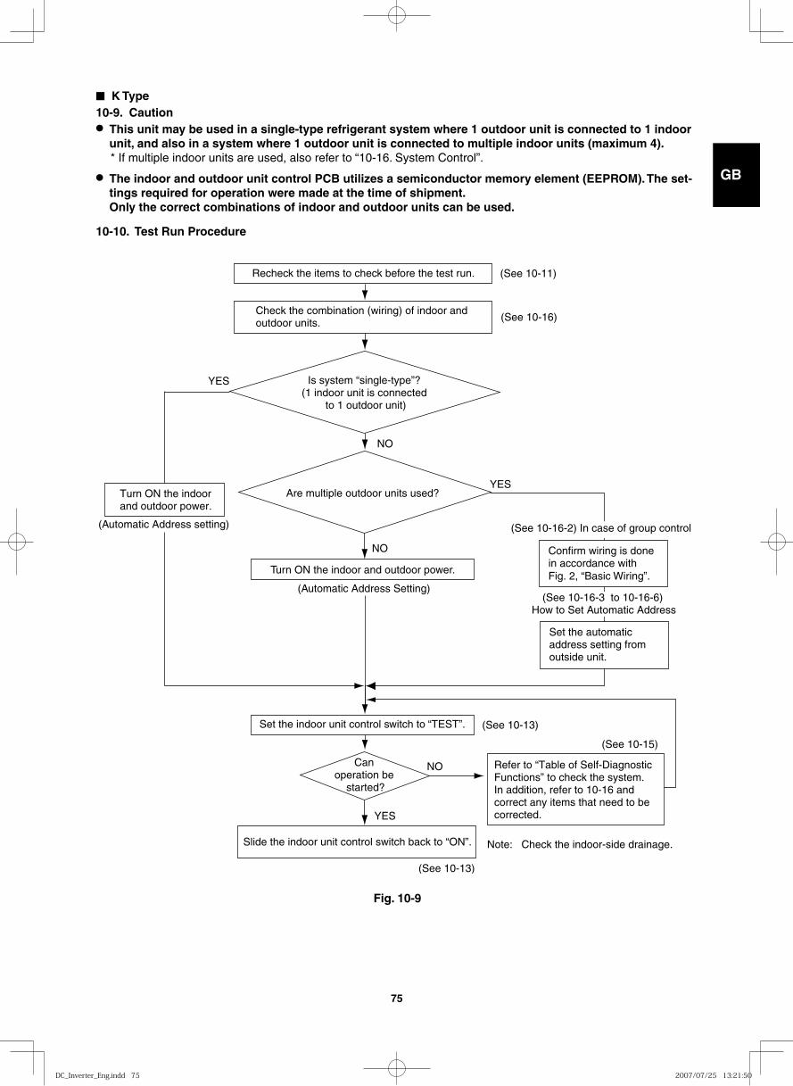
GB
FR
DE
IT
PT
GR
ES
75
■ K Type10-9. Caution ● This unit may be used in a single-type refrigerant system where 1 outdoor unit is connected to 1 indoor
unit, and also in a system where 1 outdoor unit is connected to multiple indoor units (maximum 4). * If multiple indoor units are used, also refer to “10-16. System Control”.
● The indoor and outdoor unit control PCB utilizes a semiconductor memory element (EEPROM). The set-tings required for operation were made at the time of shipment. Only the correct combinations of indoor and outdoor units can be used.
10-10. Test Run Procedure
Recheck the items to check before the test run.
Turn ON the indoor and outdoor power.
Set the indoor unit control switch to “TEST”.
Turn ON the indoor and outdoor power.
Slide the indoor unit control switch back to “ON”.
YES
NO
YES
NO
YES
NO
(See 10-13)
(See 10-13)
(See 10-15)
(See 10-11)
(See 10-16) Check the combination (wiring) of indoor and outdoor units.
Is system “single-type”? (1 indoor unit is connected
to 1 outdoor unit)
Are multiple outdoor units used?
Can operation be
started?
Refer to “Table of Self-Diagnostic Functions” to check the system. In addition, refer to 10-16 and correct any items that need to be corrected.
Note: Check the indoor-side drainage.
Confirm wiring is donein accordance with Fig. 2, “Basic Wiring”.
(Automatic Address Setting)
(See 10-16-2) In case of group control
Set the automatic address setting from outside unit.
(See 10-16-3 to 10-16-6) How to Set Automatic Address
(Automatic Address setting)
Fig. 10-9
DC_Inverter_Eng.indd 75DC_Inverter_Eng.indd 75 2007/07/25 13:21:502007/07/25 13:21:50
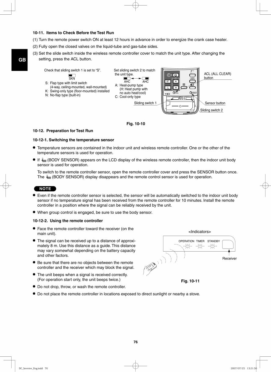
GB
FR
DE
IT
PT
GR
ES
76
10-11. Items to Check Before the Test Run
(1) Turn the remote power switch ON at least 12 hours in advance in order to energize the crank case heater.
(2) Fully open the closed valves on the liquid-tube and gas-tube sides.
(3) Set the slide switch inside the wireless remote controller cover to match the unit type. After changing the setting, press the ACL button.
10-12. Preparation for Test Run
10-12-1. Switching the temperature sensor
● Temperature sensors are contained in the indoor unit and wireless remote controller. One or the other of the temperature sensors is used for operation.
● If (BODY SENSOR) appears on the LCD display of the wireless remote controller, then the indoor unit body sensor is used for operation.
To switch to the remote controller sensor, open the remote controller cover and press the SENSOR button once. The (BODY SENSOR) display disappears and the remote control sensor is used for operation.
NOTE
● Even if the remote controller sensor is selected, the sensor will be automatically switched to the indoor unit body sensor if no temperature signal has been received from the remote controller for 10 minutes. Install the remote controller in a position where the signal can be reliably received by the unit.
● When group control is engaged, be sure to use the body sensor.
10-12-2. Using the remote controller
● Face the remote controller toward the receiver (on the main unit).
● The signal can be received up to a distance of approxi-mately 8 m. Use this distance as a guide. This distance may vary somewhat depending on the battery capacity and other factors.
● Be sure that there are no objects between the remote controller and the receiver which may block the signal.
● The unit beeps when a signal is received correctly. (For operation start only, the unit beeps twice.)
● Do not drop, throw, or wash the remote controller.
● Do not place the remote controller in locations exposed to direct sunlight or nearby a stove.
S: Flap type with limit switch (4-way, ceiling-mounted, wall-mounted)K: Swing-only type (floor-mounted) installedN: No-flap type (built-in)
Check that sliding switch 1 is set to “S”. Set sliding switch 2 to match the unit type.
A: Heat-pump type (H: Heat pump with no auto heat/cool)C: Cool-only type
Sliding switch 1
SKNAHC AHC
ACL (ALL CLEAR) button
Sensor button
Sliding switch 2
<Indicators>
OPERATION TIMER STANDBY
Receiver
Fig. 10-10
Fig. 10-11
DC_Inverter_Eng.indd 76DC_Inverter_Eng.indd 76 2007/07/25 13:21:502007/07/25 13:21:50
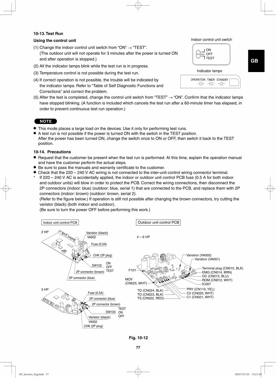
GB
FR
DE
IT
PT
GR
ES
77
10-13. Test Run
Using the control unit
(1) Change the indoor control unit switch from “ON” → “TEST”. (The outdoor unit will not operate for 3 minutes after the power is turned ON and after operation is stopped.)
(2) All the indicator lamps blink while the test run is in progress.
(3) Temperature control is not possible during the test run.
(4) If correct operation is not possible, the trouble will be indicated by the indicator lamps. Refer to “Table of Self Diagnostic Functions and Corrections” and correct the problem.
(5) After the test is completed, change the control unit switch from “TEST” → “ON”. Confirm that the indicator lamps have stopped blinking. (A function is included which cancels the test run after a 60-minute timer has elapsed, in order to prevent continuous test run operation.)
NOTE
● This mode places a large load on the devices. Use it only for performing test runs.● A test run is not possible if the power is turned ON with the switch in the TEST position.
After the power has been turned ON, change the switch once to ON or OFF, then switch it back to the TEST position.
10-14. Precautions● Request that the customer be present when the test run is performed. At this time, explain the operation manual
and have the customer perform the actual steps.● Be sure to pass the manuals and warranty certificate to the customer.● Check that the 220 – 240 V AC wiring is not connected to the inter-unit control wiring connector terminal.* If 220 – 240 V AC is accidentally applied, the indoor or outdoor unit control PCB fuse (0.5 A for both indoor
and outdoor units) will blow in order to protect the PCB. Correct the wiring connections, then disconnect the 2P connectors (indoor: blue) (outdoor: blue, serial 1) that are connected to the PCB, and replace them with 2P connectors (indoor: brown) (outdoor: brown, serial 2). (Refer to the figure below.) If operation is still not possible after changing the brown connectors, try cutting the varistor (black) (both indoor and outdoor). (Be sure to turn the power OFF before performing this work.)
2 HP
2P connector (blue)
2P connector (blue)
Fuse (0.5A)
Fuse (0.5A)
CHK (2P plug)
CHK (2P plug)
SW103ONOFFTEST
SW103TESTONOFF
2P connector (brown)
2P connector (brown)
Varistor (black)VA002
Varistor (black)VA002
Indoor unit control PCB
3 HP
Fig. 10-12
Outdoor unit control PCB
4 – 6 HP
Varistror (VA002)Varistror (VA001)
C1 (CN021, WHT)C2 (CN020, WHT)PRY (CN110, YEL)
OC (CN013, BLU)ROM (CN012, WHT)IC007
EMG (CN014, BRN)Terminal plug (CN015, BLK)
F101
TO (CN023, BLK)TS (CN022, RED)
TD (CN024, BLK)
MOV(CN025, WHT)
ONOFFTEST
Indoor control unit switch
OPERATION TIMER STANDBY
Indicator lamps
DC_Inverter_Eng.indd 77DC_Inverter_Eng.indd 77 2007/07/25 13:21:502007/07/25 13:21:50
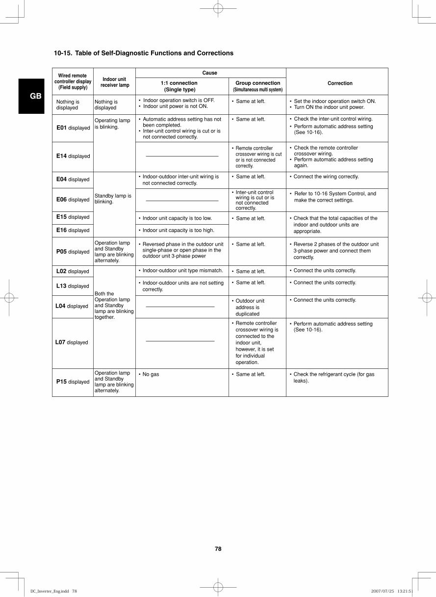
GB
FR
DE
IT
PT
GR
ES
78
10-15. Table of Self-Diagnostic Functions and Corrections
Wired remote controller display
(Field supply)
Cause
Correction
Nothing is displayed
Nothing is displayed
Operating lamp is blinking.
Standby lamp is blinking.
Operation lamp and Standby lamp are blinking alternately.
Both the Operation lamp and Standby lamp are blinking together.
Indoor unit receiver lamp
E14 displayed
E04 displayed
E06 displayed
E15 displayed
1:1 connection (Single type)
Group connection(Simultaneous multi system)
• Set the indoor operation switch ON.• Turn ON the indoor unit power.
• Check the inter-unit control wiring.• Perform automatic address setting (See 10-16).
• Check the remote controller crossover wiring. • Perform automatic address setting again.
• Connect the wiring correctly.
E01 displayed
• Refer to 10-16 System Control, and make the correct settings.
• Check that the total capacities of the indoor and outdoor units are appropriate.
• Connect the units correctly.
• Connect the units correctly.
• Connect the units correctly.
• Perform automatic address setting (See 10-16).
• Reverse 2 phases of the outdoor unit 3-phase power and connect them correctly.
• Same at left.
• Same at left.
• Remote controller crossover wiring is cut or is not connected correctly.
• Same at left.
• Inter-unit control wiring is cut or is not connected correctly.
• Same at left.
• Same at left.
• Outdoor unit address is duplicated
• Remote controller crossover wiring is connected to the indoor unit, however, it is set for individual operation.
• Same at left.
• Same at left.
• Indoor operation switch is OFF.• Indoor unit power is not ON.
• Automatic address setting has not been completed. • Inter-unit control wiring is cut or is not connected correctly.
• Indoor-outdoor inter-unit wiring is not connected correctly.
• Indoor unit capacity is too low.
• Indoor unit capacity is too high.
• Indoor-outdoor unit type mismatch.
• Indoor-outdoor units are not setting correctly.
• Reversed phase in the outdoor unit single-phase or open phase in the outdoor unit 3-phase power
E16 displayed
P05 displayed
Operation lamp and Standby lamp are blinking alternately.
• Check the refrigerant cycle (for gas leaks).
• Same at left.• No gas
P15 displayed
L02 displayed
L13 displayed
L04 displayed
L07 displayed
DC_Inverter_Eng.indd 78DC_Inverter_Eng.indd 78 2007/07/25 13:21:512007/07/25 13:21:51
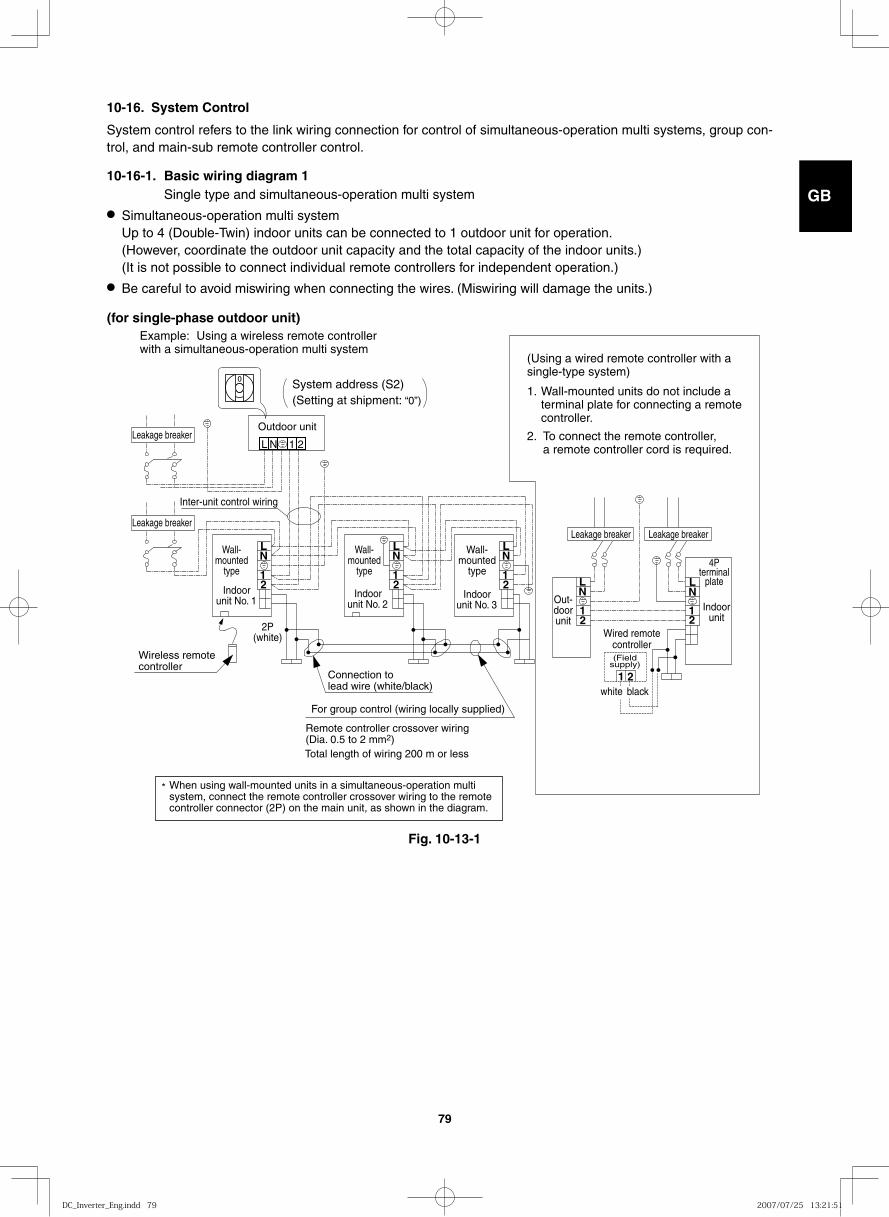
GB
FR
DE
IT
PT
GR
ES
79
L N
1 2
1 2
1 2
21
LN
21
LN
21
LN
LN
L N 1 2
Wireless remote controller
*
Connection to lead wire (white/black)
For group control (wiring locally supplied)
Wired remote controller
white black
(Field supply)
Outdoor unit
Inter-unit control wiring
Wall-mounted
type
Wall-mounted
type
Wall-mounted
type
Indoor unit No. 1
2P (white)
Indoor unit No. 2 Out-
door unit
Indoor unit
4Pterminal
plateIndoor
unit No. 3
Remote controller crossover wiring (Dia. 0.5 to 2 mm2) Total length of wiring 200 m or less
Leakage breaker Leakage breaker
Leakage breaker
Leakage breaker
(Using a wired remote controller with a single-type system)
1. Wall-mounted units do not include a terminal plate for connecting a remote controller.
2. To connect the remote controller, a remote controller cord is required.
Example: Using a wireless remote controller with a simultaneous-operation multi system
System address (S2) (Setting at shipment: “0”)
When using wall-mounted units in a simultaneous-operation multi system, connect the remote controller crossover wiring to the remote controller connector (2P) on the main unit, as shown in the diagram.
10-16. System Control
System control refers to the link wiring connection for control of simultaneous-operation multi systems, group con-trol, and main-sub remote controller control.
10-16-1. Basic wiring diagram 1 Single type and simultaneous-operation multi system● Simultaneous-operation multi system
Up to 4 (Double-Twin) indoor units can be connected to 1 outdoor unit for operation. (However, coordinate the outdoor unit capacity and the total capacity of the indoor units.) (It is not possible to connect individual remote controllers for independent operation.)
● Be careful to avoid miswiring when connecting the wires. (Miswiring will damage the units.)
Fig. 10-13-1
(for single-phase outdoor unit)
DC_Inverter_Eng.indd 79DC_Inverter_Eng.indd 79 2007/07/25 13:21:512007/07/25 13:21:51
GB
FR
DE
IT
PT
GR
ES
80
(Wiring procedure)
(1) Set the No. 1 wall-mounted indoor unit so that it can be operated by the wireless remote controller. (This is set at the time of shipment.) On the indoor unit control PCBs, set the No. 2 and following wall-mounted units to the sub remote controller. (Refer to 10-16-5.)
(2) Connect the crossover wiring to the lead wires (white/black) that extend out from the remote controller connectors of the No. 1 indoor unit and other wall-mounted indoor units (as shown in the basic wiring diagram 1 above). Connect the crossover wiring to 1 and 2 on the remote controller wiring terminal plate for units (4-way, ceiling-mounted, etc.) other than the No. 1 indoor unit.
(3) Connect the inter-unit control wiring to 1 and 2 on the No. 1 indoor unit terminal plate, and to 1 and 2 on the outdoor unit terminal plate. Also connect the inter-unit control wiring between the indoor units.
(4) When the indoor and outdoor unit power is turned ON, automatic address setting is performed (when there is only 1 outdoor unit or when the system address is “0”).
NOTE
* If the system address is “0,” automatic address setting is performed when the power is turned ON (in the case shown in basic wiring diagram 1). This requires approximately 4 – 5 minutes (when the outdoor / indoor unit ratio is 1:1 as shown in basic wiring diagram 1). During automatic address setting, LED 1 and 2 on the outdoor unit control PCB blink alternately. These LED turn OFF when automatic address setting is completed.
DC_Inverter_Eng.indd 80DC_Inverter_Eng.indd 80 2007/07/25 13:21:512007/07/25 13:21:51
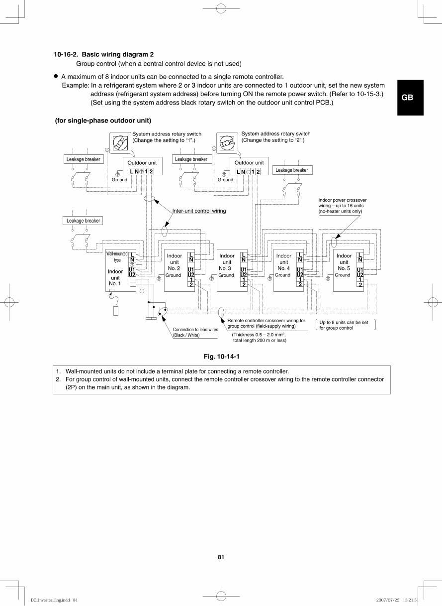
GB
FR
DE
IT
PT
GR
ES
81
10-16-2. Basic wiring diagram 2 Group control (when a central control device is not used)
● A maximum of 8 indoor units can be connected to a single remote controller. Example: In a refrigerant system where 2 or 3 indoor units are connected to 1 outdoor unit, set the new system
address (refrigerant system address) before turning ON the remote power switch. (Refer to 10-15-3.) (Set using the system address black rotary switch on the outdoor unit control PCB.)
1 2
12
U2U1
LN
U2U1
LN
12
U2U1
LN
NL 1 2NL
12
U2U1
LN
12
U2U1
LN
Leakage breaker Leakage breaker
Leakage breaker
Leakage breaker
Outdoor unit
Indoor unit
Indoor unit
Indoor unit
Indoor unit
Indoor unit
Outdoor unit
Ground Ground
GroundGroundGroundGround
System address rotary switch (Change the setting to “1”.)
System address rotary switch (Change the setting to “2”.)
Indoor power crossover wiring – up to 16 units (no-heater units only)Inter-unit control wiring
No. 1
No. 2 No. 3 No. 4 No. 5
Remote controller crossover wiring for group control (field-supply wiring)
Up to 8 units can be set for group controlConnection to lead wires
(Black / White)
Wall-mounted type
(Thickness 0.5 – 2.0 mm2, total length 200 m or less)
1. Wall-mounted units do not include a terminal plate for connecting a remote controller.2. For group control of wall-mounted units, connect the remote controller crossover wiring to the remote controller connector
(2P) on the main unit, as shown in the diagram.
Fig. 10-14-1
(for single-phase outdoor unit)
DC_Inverter_Eng.indd 81DC_Inverter_Eng.indd 81 2007/07/25 13:21:512007/07/25 13:21:51
GB
FR
DE
IT
PT
GR
ES
82
(Wiring procedure)
(1) Set the No. 1 wall-mounted indoor unit so that it can be operated by the wireless remote controller. (This is set at the time of shipment.) On the indoor unit control PCBs, set the No. 2 and following wall-mounted units to the sub remote controller. (Refer to Item 10-16-5.)
(2) Connect the crossover wiring to 1 and 2 on the remote controller wiring terminal plates of the No. 1 indoor unit and the other indoor units (as shown in the basic wiring diagram 2 above).
(3) Connect the inter-unit control wiring to 1 and 2 on the No. 1 indoor unit terminal plate, and to 1 and 2 on the outdoor unit terminal plate. Connect the wiring in the same way from the other outdoor units to U1 and U2 on the indoor units terminal plates (different refrigerant system).
(4) Perform automatic address setting from the outdoor unit. (For the automatic address setting procedure, refer to 10-16-4.)
NOTE
* Models with auxiliary heaters cannot be used for “crossover wiring” of the indoor unit power wires. (Use a pull box to divide the wiring.)
* Be sure to use the indoor unit temperature sensor (body sensor) when using this control. (Status at shipment)
DC_Inverter_Eng.indd 82DC_Inverter_Eng.indd 82 2007/07/25 13:21:512007/07/25 13:21:51
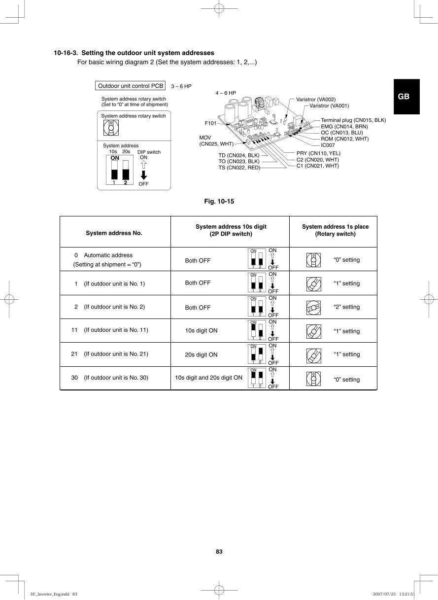
GB
FR
DE
IT
PT
GR
ES
83
10-16-3. Setting the outdoor unit system addresses For basic wiring diagram 2 (Set the system addresses: 1, 2,...)
System address No. System address 10s digit
(2P DIP switch) System address 1s place
(Rotary switch)
0 Automatic address
(Setting at shipment = “0”)
1 (If outdoor unit is No. 1)
“0” setting Both OFF
Both OFF
Both OFF
10s digit ON
20s digit ON
10s digit and 20s digit ON
“1” setting
“2” setting
“1” setting
“1” setting
“0” setting
2 (If outdoor unit is No. 2)
11 (If outdoor unit is No. 11)
21 (If outdoor unit is No. 21)
30 (If outdoor unit is No. 30)
ON ON
OFF 1 2
ON ON
OFF 1 2
ON ON
OFF 1 2
ON ON
OFF 1 2
ON ON
OFF 1 2
ON ON
OFF 1 2
ON
1 2
System address rotary switch(Set to “0” at time of shipment)
System address rotary switch
System addressDIP switch
OFF
ON10s 20s
3 – 6 HPOutdoor unit control PCB4 – 6 HP
Varistror (VA002)Varistror (VA001)
C1 (CN021, WHT)C2 (CN020, WHT)PRY (CN110, YEL)
OC (CN013, BLU)ROM (CN012, WHT)IC007
EMG (CN014, BRN)Terminal plug (CN015, BLK)
F101
TO (CN023, BLK)TS (CN022, RED)
TD (CN024, BLK)
MOV(CN025, WHT)
Fig. 10-15
DC_Inverter_Eng.indd 83DC_Inverter_Eng.indd 83 2007/07/25 13:21:512007/07/25 13:21:51
GB
FR
DE
IT
PT
GR
ES
84
10-16-4. Automatic address setting from the outdoor unit When there are multiple outdoor units as shown in basic wiring diagram 2
● If the power can be turned ON separately for the indoor and outdoor units in each system (indoor unit addresses can be set without operating the compressor):
(1) Turn ON the indoor and outdoor unit power for refrigerant system 1. Press and hold the automatic address setting button (black) for 1 second or longer at the outdoor unit where the power was turned ON.
↓ Communication for automatic address setting begins. LED 1 and 2 on the outdoor unit control PCB blink
alternately, and turn OFF when address setting is completed. ↓ <Approximately 4 – 5 minutes are required.>
(2) Next, turn ON the power only at the indoor and outdoor units in a different system. Press the automatic address setting button (black) on the outdoor unit.
↓ LED 1 and 2 on the outdoor unit control PCB blink alternately, and turn OFF when address setting is completed.
Repeat the same procedure for each system and complete automatic address setting. ↓(3) Operation using the remote controller is now possible.
10-16-5. Indoor unit remote controller main-sub setting
● When multiple wall-mounted indoor units are installed for group control in a simultaneous-operation multi sys-tem, set the control PCB at the No. 2 and following wall-mounted units to “Sub remote control”. If a wired remote controller is used, set the wired remote controller to “Sub”. If 2 wireless remote controllers are used, set the wireless PCB (DIP switch) on the second remote controller to “Sub”.
10-16-6. Indoor unit address setting● If multiple single-type units are installed in the same room, the addresses can be set to prevent signal interfer-
ence. By coordinating the numbers of the indoor unit (wireless PCB) and remote controller addresses, up to 6 indoor units can be controlled independently by their respective remote controllers.Independent control is not possible when a simultaneous-operation multi system is used.
● Checking the addressesPress the remote controller address button to display the current address on the remote controller display.If this address matches the indoor unit (wireless PCB) address, the buzzer will sound. (If ALL is set, the buzzer will always sound.)If ALL is set, operation is possible regardless of the indoor unit address.Point the remote controller toward the receiver (indoor unit) that you wish to operate, and send the operation sig-nal.
● Remote controller address settingPress and hold the address button for 4 seconds or longer to display the address on the remote controller dis-play. The current address starts blinking.The address changes each time the remote controller address button is pressed: ALL → 1 → 2 → 3 → ... → 6.Set the address to match the remote controller you wish to operate.When the SET button is pressed, the address stops blinking and displays for 5 seconds. The buzzer sounds if the address matches the indoor unit.
DC_Inverter_Eng.indd 84DC_Inverter_Eng.indd 84 2007/07/25 13:21:512007/07/25 13:21:51
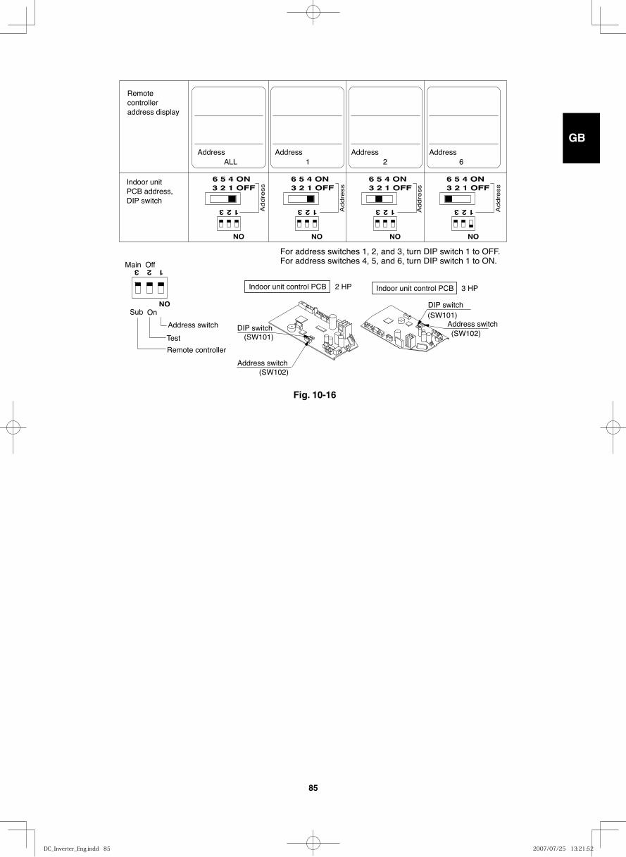
GB
FR
DE
IT
PT
GR
ES
85
123 123 123 123
6 5 4 ON3 2 1 OFF
ON
123
ON
ON ON ON
6 5 4 ON3 2 1 OFF
6 5 4 ON3 2 1 OFF
6 5 4 ON3 2 1 OFF
Address
Addre
ss
Addre
ss
Addre
ss
Addre
ss
ALL 1 2 6Address Address Address
Indoor unit control PCB 2 HP Indoor unit control PCB 3 HP
DIP switch
Address switch
(SW101)
(SW102)
DIP switch
Address switch(SW101)
(SW102)
Remote controller address display
Indoor unit PCB address, DIP switch
Main
Sub
Off
On
Address switch
Test
Remote controller
For address switches 1, 2, and 3, turn DIP switch 1 to OFF.For address switches 4, 5, and 6, turn DIP switch 1 to ON.
Fig. 10-16
DC_Inverter_Eng.indd 85DC_Inverter_Eng.indd 85 2007/07/25 13:21:522007/07/25 13:21:52
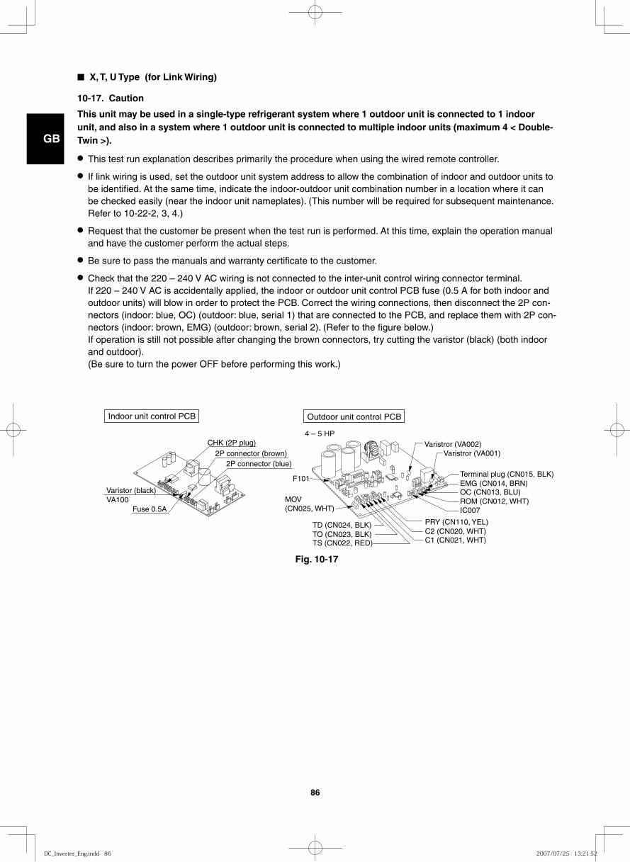
GB
FR
DE
IT
PT
GR
ES
86
■ X, T, U Type (for Link Wiring)
10-17. Caution
This unit may be used in a single-type refrigerant system where 1 outdoor unit is connected to 1 indoor unit, and also in a system where 1 outdoor unit is connected to multiple indoor units (maximum 4 < Double-Twin >).
● This test run explanation describes primarily the procedure when using the wired remote controller.
● If link wiring is used, set the outdoor unit system address to allow the combination of indoor and outdoor units to be identified. At the same time, indicate the indoor-outdoor unit combination number in a location where it can be checked easily (near the indoor unit nameplates). (This number will be required for subsequent maintenance. Refer to 10-22-2, 3, 4.)
● Request that the customer be present when the test run is performed. At this time, explain the operation manual and have the customer perform the actual steps.
● Be sure to pass the manuals and warranty certificate to the customer.
● Check that the 220 – 240 V AC wiring is not connected to the inter-unit control wiring connector terminal. If 220 – 240 V AC is accidentally applied, the indoor or outdoor unit control PCB fuse (0.5 A for both indoor and outdoor units) will blow in order to protect the PCB. Correct the wiring connections, then disconnect the 2P con-nectors (indoor: blue, OC) (outdoor: blue, serial 1) that are connected to the PCB, and replace them with 2P con-nectors (indoor: brown, EMG) (outdoor: brown, serial 2). (Refer to the figure below.) If operation is still not possible after changing the brown connectors, try cutting the varistor (black) (both indoor and outdoor). (Be sure to turn the power OFF before performing this work.)
Indoor unit control PCB Outdoor unit control PCB
Varistor (black)
Fuse 0.5A VA100
2P connector (brown) 2P connector (blue)
CHK (2P plug)
4 – 5 HPVaristror (VA002)
Varistror (VA001)
C1 (CN021, WHT)C2 (CN020, WHT)PRY (CN110, YEL)
OC (CN013, BLU)ROM (CN012, WHT)IC007
EMG (CN014, BRN)Terminal plug (CN015, BLK)
F101
TO (CN023, BLK)TS (CN022, RED)
TD (CN024, BLK)
MOV(CN025, WHT)
Fig. 10-17
DC_Inverter_Eng.indd 86DC_Inverter_Eng.indd 86 2007/07/25 13:21:522007/07/25 13:21:52
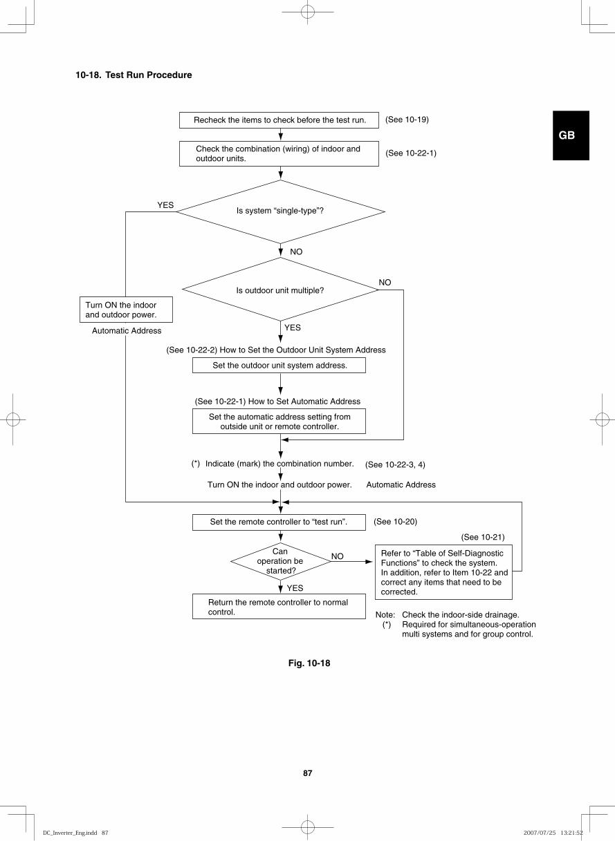
GB
FR
DE
IT
PT
GR
ES
87
Fig. 10-18
Recheck the items to check before the test run.
Set the outdoor unit system address.
Set the remote controller to “test run”.
Turn ON the indoor and outdoor power.
Return the remote controller to normal control.
YES
YES
YES
NO
NO
NO
(See 10-22-3, 4)
(See 10-20)
(See 10-21)
(See 10-19)
(See 10-22-1)Check the combination (wiring) of indoor and outdoor units.
Is system “single-type”?
Is outdoor unit multiple?
(See 10-22-2) How to Set the Outdoor Unit System Address
Set the automatic address setting fromoutside unit or remote controller.
(See 10-22-1) How to Set Automatic Address
Can operation be
started?
Refer to “Table of Self-Diagnostic Functions” to check the system. In addition, refer to Item 10-22 and correct any items that need to be corrected.
Note: Check the indoor-side drainage. (*) Required for simultaneous-operation multi systems and for group control.
Automatic Address
Automatic Address
Indicate (mark) the combination number.
Turn ON the indoor and outdoor power.
(*)
10-18. Test Run Procedure
DC_Inverter_Eng.indd 87DC_Inverter_Eng.indd 87 2007/07/25 13:21:522007/07/25 13:21:52
GB
FR
DE
IT
PT
GR
ES
88
10-19. Items to Check Before the Test Run
(1) Turn the remote power switch ON at least 12 hours in advance in order to energize the crank case heater.
(2) Fully open the closed valves on the liquid-tube and gas-tube sides.
10-20. Test Run Using the Remote Controller
(1) Press and hold the remote controller button for 4 seconds or longer. Then press the button.
● “TEST” appears in the LCD display during the test run.
● Temperature control is not possible when test run mode is engaged. (This mode places a large load on the devices. Use it only when performing the test run.)
(2) Use either Heating or Cooling mode to perform the test run.Note: The outdoor unit will not operate for approximately 3 minutes after the power is turned ON or after it stops
operating.
(3) If normal operation is not possible, a code appears on the remote controller LCD display. Refer to the “Table of Self-Diagnostic Functions and Corrections” on the next page, and correct the problem.
(4) After the test run is completed, press the button again. Check that “TEST” disappears from the LCD display. (This remote controller includes a function that cancels test run mode after a 60-minute timer has elapsed, in order to prevent continuous test run operation.)
(5) For the test run of an inverter outdoor unit, operate the compressors for a minimum of 10 minutes (in order to check for open phase).* When performing a test run using a wired remote controller, operation is possible without attaching the
cassette-type ceiling panel. (“P09” will not be displayed.)
DC_Inverter_Eng.indd 88DC_Inverter_Eng.indd 88 2007/07/25 13:21:522007/07/25 13:21:52
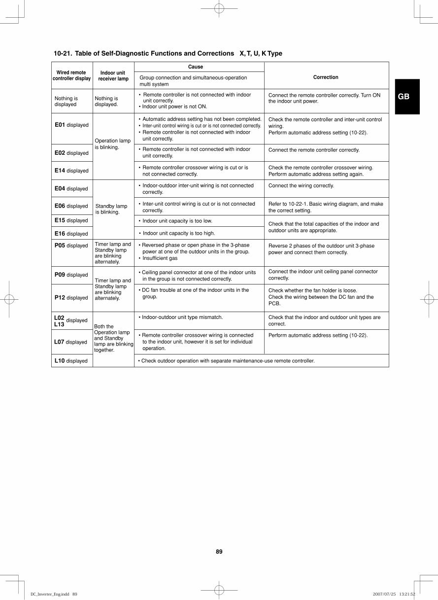
GB
FR
DE
IT
PT
GR
ES
89
Wired remote controller display
Cause
Correction
Nothing is displayed
Nothing is displayed.
Operation lamp is blinking.
Standby lamp is blinking.
Timer lamp andStandby lamp are blinking alternately.
Timer lamp andStandby lamp are blinking alternately.
Both the Operation lamp and Standby lamp are blinking together.
Indoor unit receiver lamp
E02 displayed
E14 displayed
E04 displayed
E06 displayed
E15 displayed
Group connection and simultaneous-operation multi system
• Remote controller is not connected with indoor unit correctly. • Indoor unit power is not ON.
Connect the remote controller correctly. Turn ON the indoor unit power.
Check the remote controller and inter-unit control wiring. Perform automatic address setting (10-22).
Connect the remote controller correctly.
Check the remote controller crossover wiring. Perform automatic address setting again.
Connect the wiring correctly.
E01 displayed • Automatic address setting has not been completed.• Inter-unit control wiring is cut or is not connected correctly. • Remote controller is not connected with indoor unit correctly.
• Reversed phase or open phase in the 3-phase power at one of the outdoor units in the group. • Insufficient gas
• Ceiling panel connector at one of the indoor units in the group is not connected correctly.
• DC fan trouble at one of the indoor units in the group.
• Indoor-outdoor unit type mismatch.
• Remote controller is not connected with indoor unit correctly.
• Remote controller crossover wiring is cut or is not connected correctly.
• Indoor-outdoor inter-unit wiring is not connected correctly.
Refer to 10-22-1. Basic wiring diagram, and make the correct setting.
• Inter-unit control wiring is cut or is not connected correctly.
Check that the total capacities of the indoor and outdoor units are appropriate.
Connect the indoor unit ceiling panel connector correctly.
Check whether the fan holder is loose. Check the wiring between the DC fan and the PCB.
Check that the indoor and outdoor unit types are correct.
• Remote controller crossover wiring is connected to the indoor unit, however it is set for individual operation.
Perform automatic address setting (10-22).
• Check outdoor operation with separate maintenance-use remote controller.
Reverse 2 phases of the outdoor unit 3-phase power and connect them correctly.
• Indoor unit capacity is too low.
E16 displayed
P05 displayed
P09 displayed
P12 displayed
L02L13
L10 displayed
L07 displayed
• Indoor unit capacity is too high.
displayed
10-21. Table of Self-Diagnostic Functions and Corrections X, T, U, K Type
DC_Inverter_Eng.indd 89DC_Inverter_Eng.indd 89 2007/07/25 13:21:522007/07/25 13:21:52
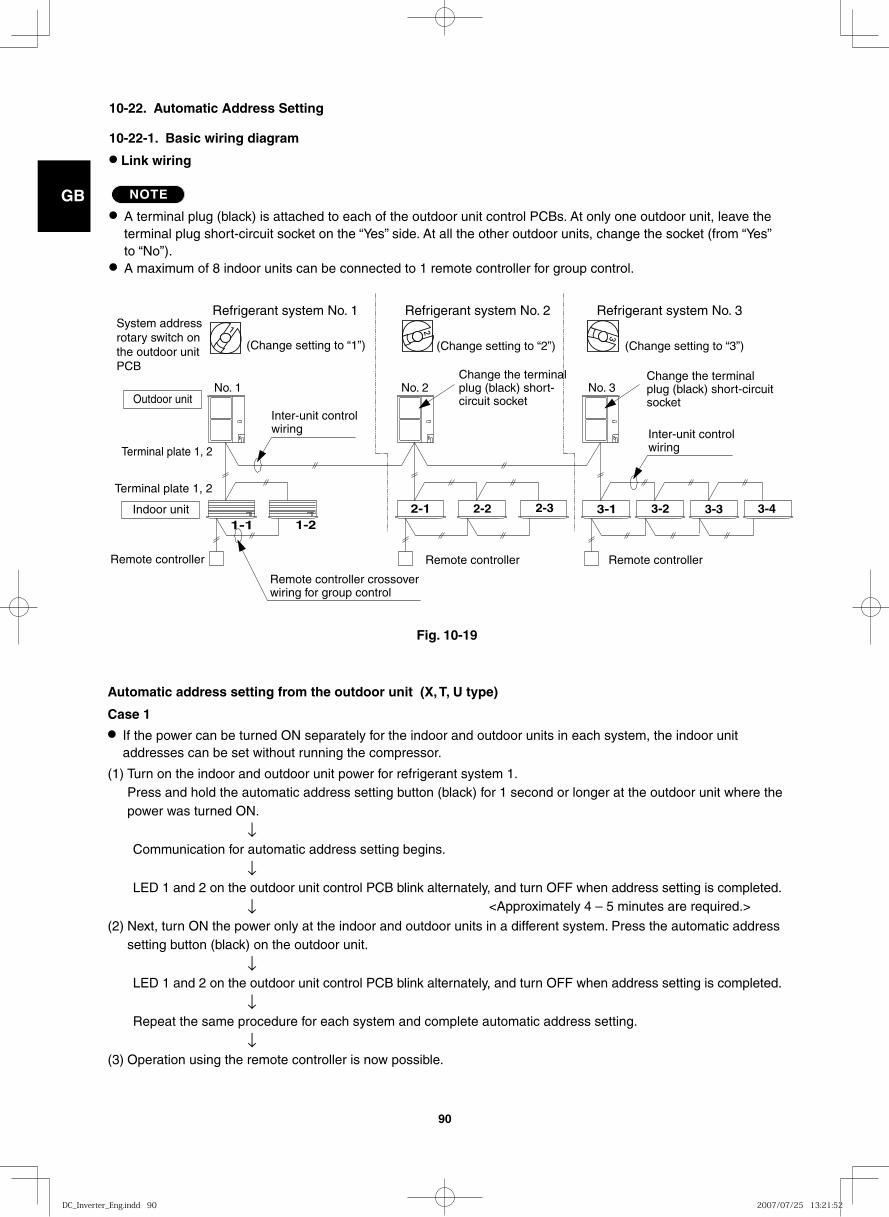
GB
FR
DE
IT
PT
GR
ES
90
10-22. Automatic Address Setting
10-22-1. Basic wiring diagram
● Link wiring
NOTE
● A terminal plug (black) is attached to each of the outdoor unit control PCBs. At only one outdoor unit, leave the terminal plug short-circuit socket on the “Yes” side. At all the other outdoor units, change the socket (from “Yes” to “No”).
● A maximum of 8 indoor units can be connected to 1 remote controller for group control.
3-1 3-21-1 1-2
2-1 2-2 2-3 3-3 3-4
Refrigerant system No. 1 Refrigerant system No. 2 Refrigerant system No. 3
(Change setting to “1”) (Change setting to “2”) (Change setting to “3”)
No. 1 No. 2 No. 3
Inter-unit controlwiring Inter-unit control
wiringTerminal plate 1, 2
Terminal plate 1, 2
Outdoor unit
Indoor unit
Remote controller
Remote controller crossoverwiring for group control
Remote controller Remote controller
Change the terminalplug (black) short-circuit socket
Change the terminalplug (black) short-circuitsocket
System address rotary switch on the outdoor unit PCB
Automatic address setting from the outdoor unit (X, T, U type)
Case 1● If the power can be turned ON separately for the indoor and outdoor units in each system, the indoor unit
addresses can be set without running the compressor.
(1) Turn on the indoor and outdoor unit power for refrigerant system 1. Press and hold the automatic address setting button (black) for 1 second or longer at the outdoor unit where the power was turned ON.
↓ Communication for automatic address setting begins. ↓ LED 1 and 2 on the outdoor unit control PCB blink alternately, and turn OFF when address setting is completed. ↓ <Approximately 4 – 5 minutes are required.>
(2) Next, turn ON the power only at the indoor and outdoor units in a different system. Press the automatic address setting button (black) on the outdoor unit.
↓ LED 1 and 2 on the outdoor unit control PCB blink alternately, and turn OFF when address setting is completed. ↓ Repeat the same procedure for each system and complete automatic address setting. ↓(3) Operation using the remote controller is now possible.
Fig. 10-19
DC_Inverter_Eng.indd 90DC_Inverter_Eng.indd 90 2007/07/25 13:21:522007/07/25 13:21:52
GB
FR
DE
IT
PT
GR
ES
91
Case 2
● If the power cannot be turned ON separately for the indoor and outdoor units in each system: The compressors must be run in order to automatically set the indoor unit addresses. Therefore perform this step after completing the refrigerant tubing work.
(1) Turn ON the power to the indoor and outdoor units in all refrigerant systems. ↓When setting addresses in cooling mode(2) Short-circuit the mode-change pin at the outdoor unit where automatic address setting will be performed. Then
press the automatic address setting button (black). ↓When setting addresses in heating mode(2) Press the automatic address setting button (black) at the outdoor unit where automatic address setting will be
performed. ↓(3) LED 1 and 2 blink alternately. The compressors begin running in Cooling (or Heating) mode. Communication for
automatic address setting begins, using the temperature changes at the indoor units. <All indoor units are in operating status.> ↓ Address setting is completed when the compressors stop and the LED indicators turn OFF. <Approximately 15
minutes is required for 1 system.> If address setting fails, LED 1 and 2 blink simultaneously and the alarm contents are displayed at the remote controller.
(4) After 1 system is completed, be sure to press the automatic address setting button (black) at the other outdoor units to complete automatic address setting in the same way for each system.
(5) Operation using the remote controller is now possible.
Automatic address setting using the remote controller
Case 3● If the power can be turned ON separately for the indoor and outdoor units in each system (indoor unit addresses
can be set without running the compressor):
Individual system automatic address setting: Display item code “A1”.
(1) Press the remote controller timer time button and button simultaneously. (Hold for 4 seconds or longer.)
↓ (2) Then press either the temperature setting or button.
(Confirm that the item code is “A1”.) ↓ (3) Use either the or button to select the outdoor unit to perform automatic address setting for.
Then press the button. (“R.C.1” is displayed, and automatic address setting is performed for refrigerant system 1.) When automatic address setting for system 1 is completed, the units return to normal stopped status. <Approximately 4 – 5 minutes are required.>
During automatic address setting, “SETTING” blinks on the remote controller display. This display disappears when address setting is completed.
DC_Inverter_Eng.indd 91DC_Inverter_Eng.indd 91 2007/07/25 13:21:522007/07/25 13:21:52
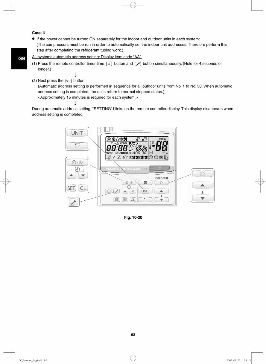
GB
FR
DE
IT
PT
GR
ES
92
Case 4● If the power cannot be turned ON separately for the indoor and outdoor units in each system:
(The compressors must be run in order to automatically set the indoor unit addresses. Therefore perform this step after completing the refrigerant tubing work.)
All-systems automatic address setting: Display item code “AA”.
(1) Press the remote controller timer time button and button simultaneously. (Hold for 4 seconds or longer.)
↓ (2) Next press the button.
(Automatic address setting is performed in sequence for all outdoor units from No. 1 to No. 30. When automatic address setting is completed, the units return to normal stopped status.) <Approximately 15 minutes is required for each system.>
↓ During automatic address setting, “SETTING” blinks on the remote controller display. This display disappears when address setting is completed.
Fig. 10-20
DC_Inverter_Eng.indd 92DC_Inverter_Eng.indd 92 2007/07/25 13:21:532007/07/25 13:21:53
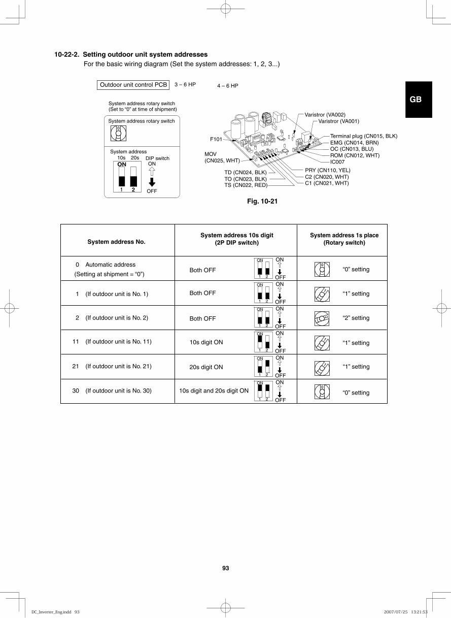
GB
FR
DE
IT
PT
GR
ES
93
10-22-2. Setting outdoor unit system addresses For the basic wiring diagram (Set the system addresses: 1, 2, 3...)
ON
1 2
System address rotary switch(Set to “0” at time of shipment)
System address rotary switch
System addressDIP switch
OFF
ON10s 20s
Outdoor unit control PCB 3 – 6 HP
System address No. System address 10s digit
(2P DIP switch) System address 1s place
(Rotary switch)
0 Automatic address
(Setting at shipment = “0”)
1 (If outdoor unit is No. 1)
“0” setting Both OFF
Both OFF
Both OFF
10s digit ON
20s digit ON
10s digit and 20s digit ON
“1” setting
“2” setting
“1” setting
“1” setting
“0” setting
2 (If outdoor unit is No. 2)
11 (If outdoor unit is No. 11)
21 (If outdoor unit is No. 21)
30 (If outdoor unit is No. 30)
ON ON
OFF 1 2
ON ON
OFF 1 2
ON ON
OFF 1 2
ON ON
OFF 1 2
ON ON
OFF 1 2
ON ON
OFF 1 2
4 – 6 HP
Varistror (VA002)Varistror (VA001)
C1 (CN021, WHT)C2 (CN020, WHT)PRY (CN110, YEL)
OC (CN013, BLU)ROM (CN012, WHT)IC007
EMG (CN014, BRN)Terminal plug (CN015, BLK)
F101
TO (CN023, BLK)TS (CN022, RED)
TD (CN024, BLK)
MOV(CN025, WHT)
Fig. 10-21
DC_Inverter_Eng.indd 93DC_Inverter_Eng.indd 93 2007/07/25 13:21:532007/07/25 13:21:53
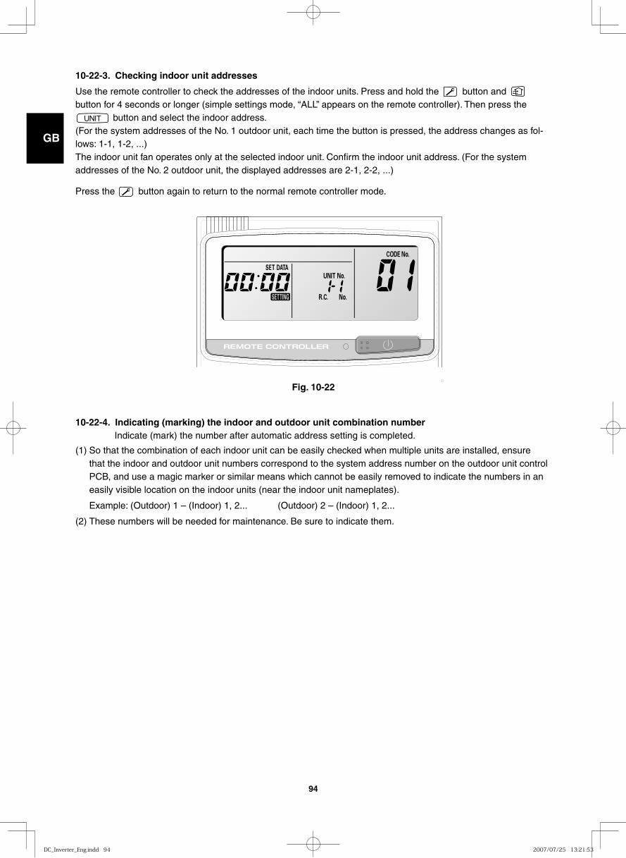
GB
FR
DE
IT
PT
GR
ES
94
10-22-3. Checking indoor unit addresses
Use the remote controller to check the addresses of the indoor units. Press and hold the button and button for 4 seconds or longer (simple settings mode, “ALL” appears on the remote controller). Then press the
button and select the indoor address. (For the system addresses of the No. 1 outdoor unit, each time the button is pressed, the address changes as fol-lows: 1-1, 1-2, ...)The indoor unit fan operates only at the selected indoor unit. Confirm the indoor unit address. (For the system addresses of the No. 2 outdoor unit, the displayed addresses are 2-1, 2-2, ...)
Press the button again to return to the normal remote controller mode.
10-22-4. Indicating (marking) the indoor and outdoor unit combination number Indicate (mark) the number after automatic address setting is completed.
(1) So that the combination of each indoor unit can be easily checked when multiple units are installed, ensure that the indoor and outdoor unit numbers correspond to the system address number on the outdoor unit control PCB, and use a magic marker or similar means which cannot be easily removed to indicate the numbers in an easily visible location on the indoor units (near the indoor unit nameplates).
Example: (Outdoor) 1 – (Indoor) 1, 2... (Outdoor) 2 – (Indoor) 1, 2...
(2) These numbers will be needed for maintenance. Be sure to indicate them.
Fig. 10-22
DC_Inverter_Eng.indd 94DC_Inverter_Eng.indd 94 2007/07/25 13:21:532007/07/25 13:21:53
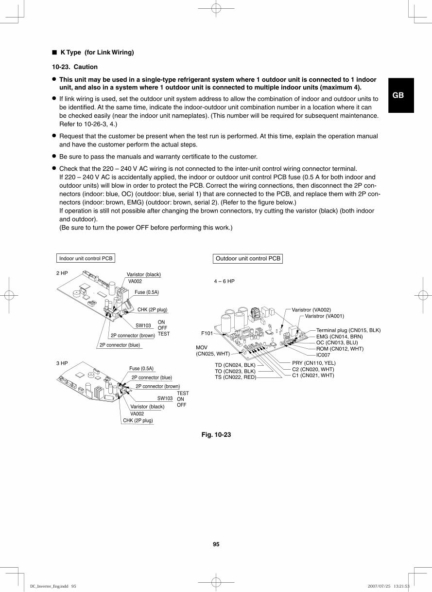
GB
FR
DE
IT
PT
GR
ES
95
■ K Type (for Link Wiring)
10-23. Caution
● This unit may be used in a single-type refrigerant system where 1 outdoor unit is connected to 1 indoor unit, and also in a system where 1 outdoor unit is connected to multiple indoor units (maximum 4).
● If link wiring is used, set the outdoor unit system address to allow the combination of indoor and outdoor units to be identified. At the same time, indicate the indoor-outdoor unit combination number in a location where it can be checked easily (near the indoor unit nameplates). (This number will be required for subsequent maintenance. Refer to 10-26-3, 4.)
● Request that the customer be present when the test run is performed. At this time, explain the operation manual and have the customer perform the actual steps.
● Be sure to pass the manuals and warranty certificate to the customer.
● Check that the 220 – 240 V AC wiring is not connected to the inter-unit control wiring connector terminal. If 220 – 240 V AC is accidentally applied, the indoor or outdoor unit control PCB fuse (0.5 A for both indoor and outdoor units) will blow in order to protect the PCB. Correct the wiring connections, then disconnect the 2P con-nectors (indoor: blue, OC) (outdoor: blue, serial 1) that are connected to the PCB, and replace them with 2P con-nectors (indoor: brown, EMG) (outdoor: brown, serial 2). (Refer to the figure below.) If operation is still not possible after changing the brown connectors, try cutting the varistor (black) (both indoor and outdoor). (Be sure to turn the power OFF before performing this work.)
2 HP
2P connector (blue)
2P connector (blue)
Fuse (0.5A)
Fuse (0.5A)
CHK (2P plug)
CHK (2P plug)
SW103ONOFFTEST
SW103TESTONOFF
2P connector (brown)
2P connector (brown)
Varistor (black)VA002
Varistor (black)VA002
Indoor unit control PCB
3 HP
Fig. 10-23
Outdoor unit control PCB
4 – 6 HP
Varistror (VA002)Varistror (VA001)
C1 (CN021, WHT)C2 (CN020, WHT)PRY (CN110, YEL)
OC (CN013, BLU)ROM (CN012, WHT)IC007
EMG (CN014, BRN)Terminal plug (CN015, BLK)
F101
TO (CN023, BLK)TS (CN022, RED)
TD (CN024, BLK)
MOV(CN025, WHT)
DC_Inverter_Eng.indd 95DC_Inverter_Eng.indd 95 2007/07/25 13:21:532007/07/25 13:21:53
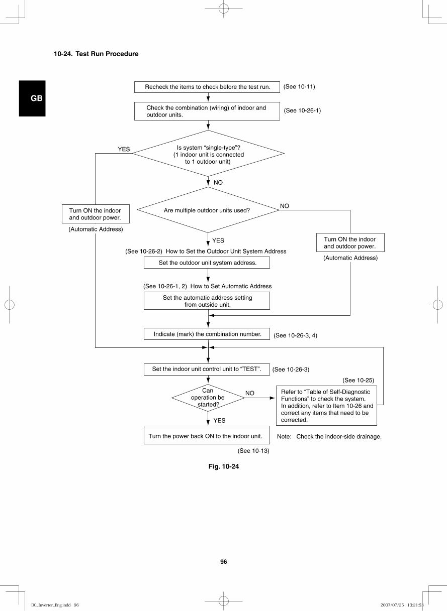
GB
FR
DE
IT
PT
GR
ES
96
10-24. Test Run Procedure
Recheck the items to check before the test run.
Indicate (mark) the combination number.
Set the outdoor unit system address.
(See 10-26-2) How to Set the Outdoor Unit System Address
Set the automatic address settingfrom outside unit.
(See 10-26-1, 2) How to Set Automatic Address
Set the indoor unit control unit to “TEST”.
Turn ON the indoor and outdoor power.
Turn the power back ON to the indoor unit.
YES
NO
YES
NO
YES
NO
(See 10-26-3, 4)
(See 10-26-3)
(See 10-13)
(See 10-25)
(See 10-11)
(See 10-26-1)Check the combination (wiring) of indoor and outdoor units.
Is system “single-type”?(1 indoor unit is connected
to 1 outdoor unit)
Are multiple outdoor units used?
Can operation be
started?
Refer to “Table of Self-Diagnostic Functions” to check the system. In addition, refer to Item 10-26 and correct any items that need to be corrected.
Note: Check the indoor-side drainage.
(Automatic Address)
Turn ON the indoor and outdoor power.
(Automatic Address)
Fig. 10-24
DC_Inverter_Eng.indd 96DC_Inverter_Eng.indd 96 2007/07/25 13:21:532007/07/25 13:21:53
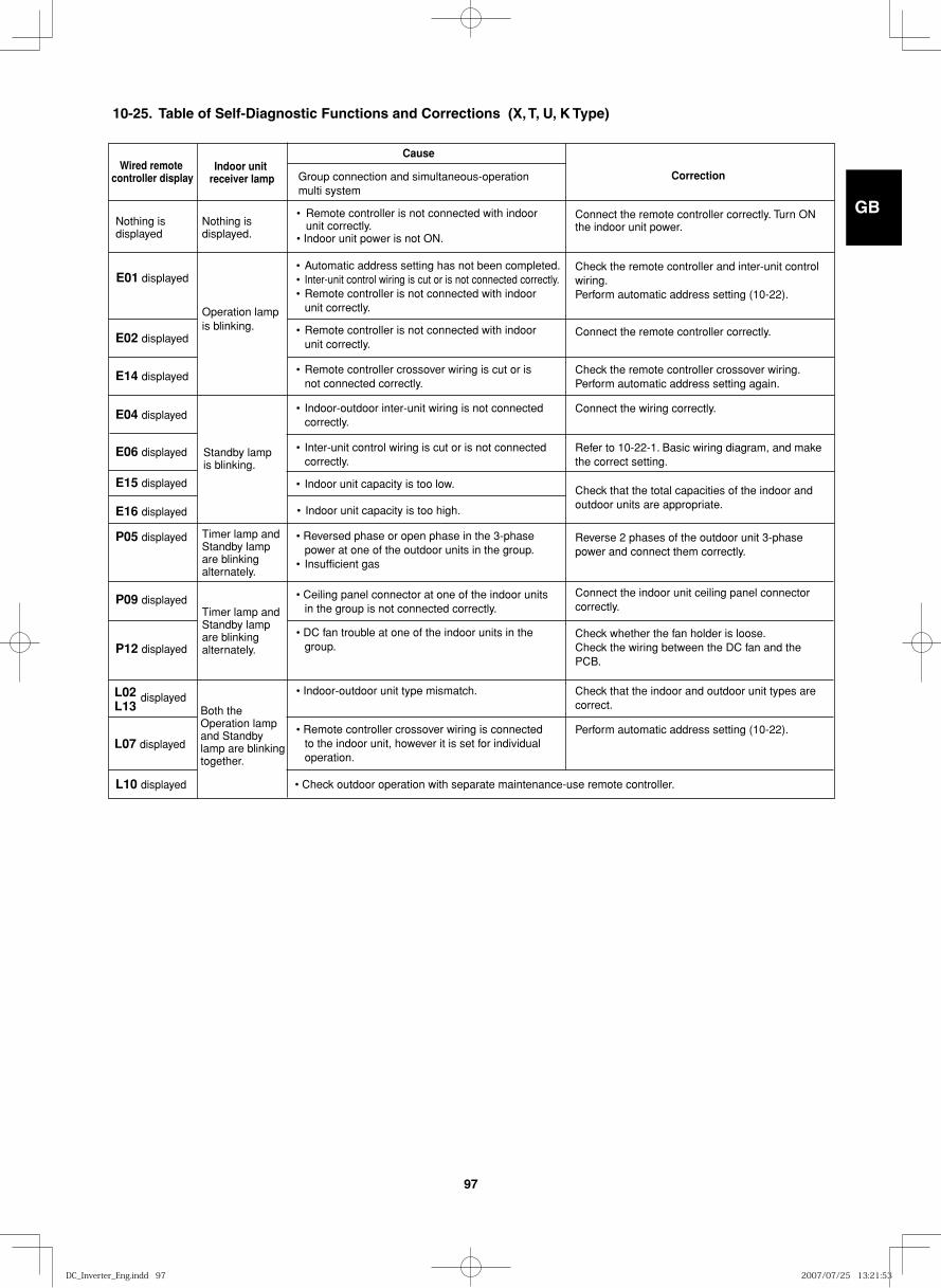
GB
FR
DE
IT
PT
GR
ES
97
Wired remote controller display
Cause
Correction
Nothing is displayed
Nothing is displayed.
Operation lamp is blinking.
Standby lamp is blinking.
Timer lamp andStandby lamp are blinking alternately.
Timer lamp andStandby lamp are blinking alternately.
Both the Operation lamp and Standby lamp are blinking together.
Indoor unit receiver lamp
E02 displayed
E14 displayed
E04 displayed
E06 displayed
E15 displayed
Group connection and simultaneous-operation multi system
• Remote controller is not connected with indoor unit correctly. • Indoor unit power is not ON.
Connect the remote controller correctly. Turn ON the indoor unit power.
Check the remote controller and inter-unit control wiring. Perform automatic address setting (10-22).
Connect the remote controller correctly.
Check the remote controller crossover wiring. Perform automatic address setting again.
Connect the wiring correctly.
E01 displayed • Automatic address setting has not been completed.• Inter-unit control wiring is cut or is not connected correctly. • Remote controller is not connected with indoor unit correctly.
• Reversed phase or open phase in the 3-phase power at one of the outdoor units in the group. • Insufficient gas
• Ceiling panel connector at one of the indoor units in the group is not connected correctly.
• DC fan trouble at one of the indoor units in the group.
• Indoor-outdoor unit type mismatch.
• Remote controller is not connected with indoor unit correctly.
• Remote controller crossover wiring is cut or is not connected correctly.
• Indoor-outdoor inter-unit wiring is not connected correctly.
Refer to 10-22-1. Basic wiring diagram, and make the correct setting.
• Inter-unit control wiring is cut or is not connected correctly.
Check that the total capacities of the indoor and outdoor units are appropriate.
Connect the indoor unit ceiling panel connector correctly.
Check whether the fan holder is loose. Check the wiring between the DC fan and the PCB.
Check that the indoor and outdoor unit types are correct.
• Remote controller crossover wiring is connected to the indoor unit, however it is set for individual operation.
Perform automatic address setting (10-22).
• Check outdoor operation with separate maintenance-use remote controller.
Reverse 2 phases of the outdoor unit 3-phase power and connect them correctly.
• Indoor unit capacity is too low.
E16 displayed
P05 displayed
P09 displayed
P12 displayed
L02L13
L10 displayed
L07 displayed
• Indoor unit capacity is too high.
displayed
10-25. Table of Self-Diagnostic Functions and Corrections (X, T, U, K Type)
DC_Inverter_Eng.indd 97DC_Inverter_Eng.indd 97 2007/07/25 13:21:532007/07/25 13:21:53
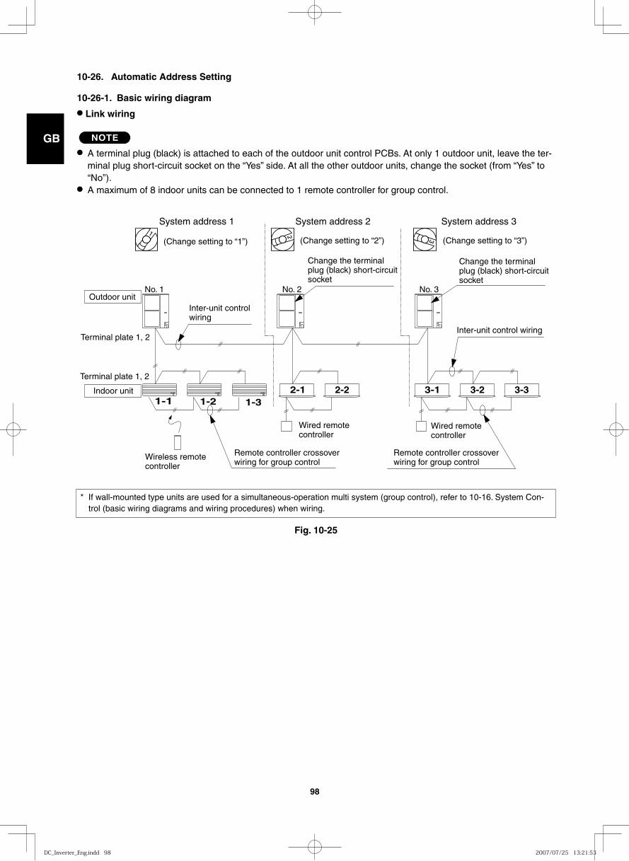
GB
FR
DE
IT
PT
GR
ES
98
3-1 3-2 3-31-1 1-2 1-3
2-1 2-2
System address 1
(Change setting to “1”)
System address 2
(Change setting to “2”) (Change setting to “3”)
System address 3
No. 3No. 2No. 1Outdoor unit
Inter-unit controlwiring
Terminal plate 1, 2
Terminal plate 1, 2
Indoor unit
Change the terminalplug (black) short-circuitsocket
Change the terminalplug (black) short-circuitsocket
Inter-unit control wiring
Wired remotecontroller
Wireless remotecontroller
Wired remotecontroller
Remote controller crossoverwiring for group control
Remote controller crossoverwiring for group control
10-26. Automatic Address Setting
10-26-1. Basic wiring diagram
● Link wiring
NOTE
● A terminal plug (black) is attached to each of the outdoor unit control PCBs. At only 1 outdoor unit, leave the ter-minal plug short-circuit socket on the “Yes” side. At all the other outdoor units, change the socket (from “Yes” to “No”).
● A maximum of 8 indoor units can be connected to 1 remote controller for group control.
* If wall-mounted type units are used for a simultaneous-operation multi system (group control), refer to 10-16. System Con-trol (basic wiring diagrams and wiring procedures) when wiring.
Fig. 10-25
DC_Inverter_Eng.indd 98DC_Inverter_Eng.indd 98 2007/07/25 13:21:532007/07/25 13:21:53
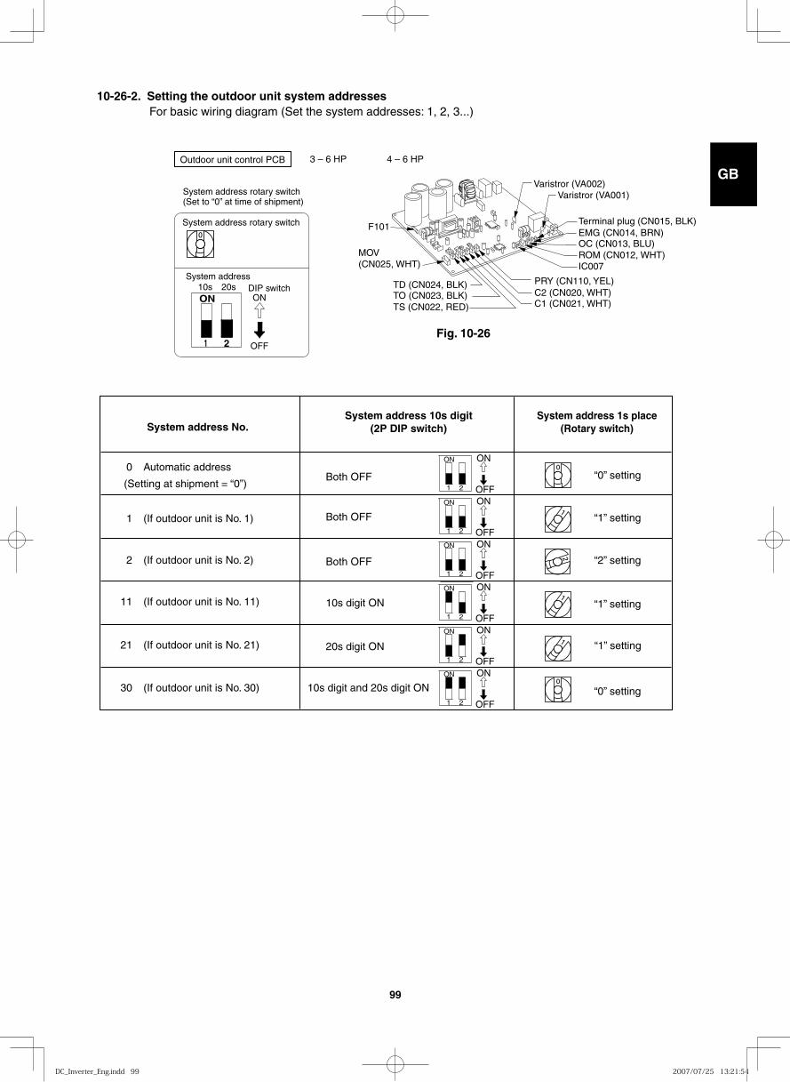
GB
FR
DE
IT
PT
GR
ES
99
10-26-2. Setting the outdoor unit system addresses For basic wiring diagram (Set the system addresses: 1, 2, 3...)
4 – 6 HP
Varistror (VA002)Varistror (VA001)
C1 (CN021, WHT)C2 (CN020, WHT)PRY (CN110, YEL)
OC (CN013, BLU)ROM (CN012, WHT)IC007
EMG (CN014, BRN)Terminal plug (CN015, BLK)
F101
TO (CN023, BLK)TS (CN022, RED)
TD (CN024, BLK)
MOV(CN025, WHT)
System address No. System address 10s digit
(2P DIP switch) System address 1s place
(Rotary switch)
0 Automatic address
(Setting at shipment = “0”)
1 (If outdoor unit is No. 1)
“0” setting Both OFF
Both OFF
Both OFF
10s digit ON
20s digit ON
10s digit and 20s digit ON
“1” setting
“2” setting
“1” setting
“1” setting
“0” setting
2 (If outdoor unit is No. 2)
11 (If outdoor unit is No. 11)
21 (If outdoor unit is No. 21)
30 (If outdoor unit is No. 30)
ON ON
OFF 1 2
ON ON
OFF 1 2
ON ON
OFF 1 2
ON ON
OFF 1 2
ON ON
OFF 1 2
ON ON
OFF 1 2
Fig. 10-26
ON
1 2
System address rotary switch(Set to “0” at time of shipment)
System address rotary switch
System addressDIP switch
OFF
ON10s 20s
Outdoor unit control PCB 3 – 6 HP
DC_Inverter_Eng.indd 99DC_Inverter_Eng.indd 99 2007/07/25 13:21:542007/07/25 13:21:54
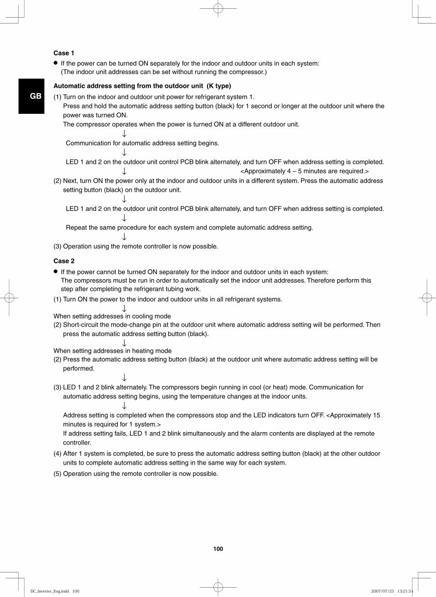
GB
FR
DE
IT
PT
GR
ES
100
Case 1● If the power can be turned ON separately for the indoor and outdoor units in each system:
(The indoor unit addresses can be set without running the compressor.)
Automatic address setting from the outdoor unit (K type)
(1) Turn on the indoor and outdoor unit power for refrigerant system 1. Press and hold the automatic address setting button (black) for 1 second or longer at the outdoor unit where the power was turned ON.The compressor operates when the power is turned ON at a different outdoor unit.
↓ Communication for automatic address setting begins. ↓ LED 1 and 2 on the outdoor unit control PCB blink alternately, and turn OFF when address setting is completed. ↓ <Approximately 4 – 5 minutes are required.>
(2) Next, turn ON the power only at the indoor and outdoor units in a different system. Press the automatic address setting button (black) on the outdoor unit.
↓ LED 1 and 2 on the outdoor unit control PCB blink alternately, and turn OFF when address setting is completed. ↓ Repeat the same procedure for each system and complete automatic address setting. ↓(3) Operation using the remote controller is now possible.
Case 2
● If the power cannot be turned ON separately for the indoor and outdoor units in each system: The compressors must be run in order to automatically set the indoor unit addresses. Therefore perform this step after completing the refrigerant tubing work.
(1) Turn ON the power to the indoor and outdoor units in all refrigerant systems. ↓When setting addresses in cooling mode (2) Short-circuit the mode-change pin at the outdoor unit where automatic address setting will be performed. Then
press the automatic address setting button (black). ↓When setting addresses in heating mode (2) Press the automatic address setting button (black) at the outdoor unit where automatic address setting will be
performed. ↓(3) LED 1 and 2 blink alternately. The compressors begin running in cool (or heat) mode. Communication for
automatic address setting begins, using the temperature changes at the indoor units. ↓ Address setting is completed when the compressors stop and the LED indicators turn OFF. <Approximately 15
minutes is required for 1 system.> If address setting fails, LED 1 and 2 blink simultaneously and the alarm contents are displayed at the remote controller.
(4) After 1 system is completed, be sure to press the automatic address setting button (black) at the other outdoor units to complete automatic address setting in the same way for each system.
(5) Operation using the remote controller is now possible.
DC_Inverter_Eng.indd 100DC_Inverter_Eng.indd 100 2007/07/25 13:21:542007/07/25 13:21:54
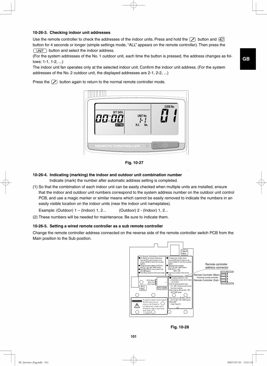
GB
FR
DE
IT
PT
GR
ES
101
10-26-3. Checking indoor unit addresses
Use the remote controller to check the addresses of the indoor units. Press and hold the button and button for 4 seconds or longer (simple settings mode, “ALL” appears on the remote controller). Then press the
button and select the indoor address. (For the system addresses of the No. 1 outdoor unit, each time the button is pressed, the address changes as fol-lows: 1-1, 1-2, ...)The indoor unit fan operates only at the selected indoor unit. Confirm the indoor unit address. (For the system addresses of the No. 2 outdoor unit, the displayed addresses are 2-1, 2-2, ...)
Press the button again to return to the normal remote controller mode.
10-26-4. Indicating (marking) the indoor and outdoor unit combination number Indicate (mark) the number after automatic address setting is completed.
(1) So that the combination of each indoor unit can be easily checked when multiple units are installed, ensure that the indoor and outdoor unit numbers correspond to the system address number on the outdoor unit control PCB, and use a magic marker or similar means which cannot be easily removed to indicate the numbers in an easily visible location on the indoor units (near the indoor unit nameplates).
Example: (Outdoor) 1 – (Indoor) 1, 2... (Outdoor) 2 - (Indoor) 1, 2...
(2) These numbers will be needed for maintenance. Be sure to indicate them.
10-26-5. Setting a wired remote controller as a sub remote controller
Change the remote controller address connected on the reverse side of the remote controller switch PCB from the Main position to the Sub position.
Fig. 10-27
Fig. 10-28
TIMERTMNL.
RCUTMNL. RCU.ADR
RCU.Main
RCU.SubRCU.CK
To Service TechniciansTo display the sensor temperature:
WARNINGTo avoid an e lect r ic shock hazard,DO NOT touch any ter -mina l on the Pr in ted Ci r -cu i t Board wi th a meta l rod, ascrewdr iver edge or bare handwhen power is suppl ied.
Press both and buttons on the remote controller for more than 4 seconds together.Change the sensor address (CODE NO.) with / (SET TEMP) buttons.Select the UNIT NO. that you want to call with button.Press the button to finish service mode.
To display the trouble history:Press both and buttons on the remote controller for more than 4 seconds together.Change the alarm message: / (SET TEMP) buttonsCODE NO.
Press the button to finish service mode.
On the remote controller, press + + at the same time for more than 4 seconds.Set CODE No. with /(SET TEMP) button.
Set DATA from towith / (TIMER) button.PressFinally, Press
(New) (Old)
Changing method for room temperature sensor (from Indoor unit to RCU)
1
2
3
4
Remote Controller (Sub)
Remote controller address connector
Remote Controller (Main)Checking remote controller
DC_Inverter_Eng.indd 101DC_Inverter_Eng.indd 101 2007/07/25 13:21:542007/07/25 13:21:54
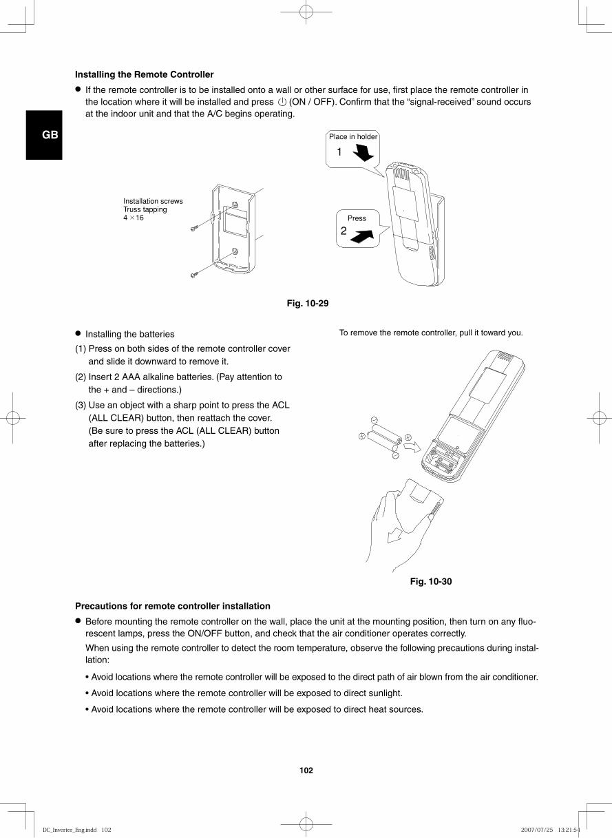
GB
FR
DE
IT
PT
GR
ES
102
Installing the Remote Controller
● If the remote controller is to be installed onto a wall or other surface for use, first place the remote controller in the location where it will be installed and press (ON / OFF). Confirm that the “signal-received” sound occurs at the indoor unit and that the A/C begins operating.
Place in holder
Installation screwsTruss tapping4 16 Press
1
2
● Installing the batteries
(1) Press on both sides of the remote controller cover and slide it downward to remove it.
(2) Insert 2 AAA alkaline batteries. (Pay attention to the + and – directions.)
(3) Use an object with a sharp point to press the ACL (ALL CLEAR) button, then reattach the cover. (Be sure to press the ACL (ALL CLEAR) button after replacing the batteries.)
Fig. 10-29
Fig. 10-30
To remove the remote controller, pull it toward you.
Precautions for remote controller installation
● Before mounting the remote controller on the wall, place the unit at the mounting position, then turn on any fluo-rescent lamps, press the ON/OFF button, and check that the air conditioner operates correctly.
When using the remote controller to detect the room temperature, observe the following precautions during instal-lation:
• Avoid locations where the remote controller will be exposed to the direct path of air blown from the air conditioner.
• Avoid locations where the remote controller will be exposed to direct sunlight.
• Avoid locations where the remote controller will be exposed to direct heat sources.
DC_Inverter_Eng.indd 102DC_Inverter_Eng.indd 102 2007/07/25 13:21:542007/07/25 13:21:54
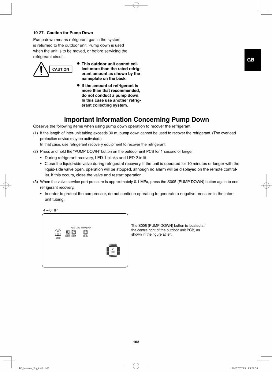
GB
FR
DE
IT
PT
GR
ES
103
10-27. Caution for Pump Down
Pump down means refrigerant gas in the system is returned to the outdoor unit. Pump down is used when the unit is to be moved, or before servicing the refrigerant circuit.
CAUTION
● This outdoor unit cannot col-lect more than the rated refrig-erant amount as shown by the nameplate on the back.
● If the amount of refrigerant is more than that recommended, do not conduct a pump down. In this case use another refrig-erant collecting system.
Important Information Concerning Pump DownObserve the following items when using pump down operation to recover the refrigerant.
(1) If the length of inter-unit tubing exceeds 30 m, pump down cannot be used to recover the refrigerant. (The overload
protection device may be activated.)
In that case, use refrigerant recovery equipment to recover the refrigerant.
(2) Press and hold the “PUMP DOWN” button on the outdoor unit PCB for 1 second or longer.
• During refrigerant recovery, LED 1 blinks and LED 2 is lit.
• Close the liquid-side valve during refrigerant recovery. If the unit is operated for 10 minutes or longer with the liquid-side valve open, operation will be stopped, although no alarm will be displayed on the remote control-ler. If this occurs, close the valve and restart operation.
(3) When the valve service port pressure is approximately 0.1 MPa, press the S005 (PUMP DOWN) button again to end
refrigerant recovery.
• In order to protect the compressor, do not continue operating to generate a negative pressure in the inter-unit tubing.
The S005 (PUMP DOWN) button is located at the centre right of the outdoor unit PCB, as shown in the figure at left.
4 – 6 HP
S002S003 S001
AUTO ADD PUMP DOWN
S005
IC001
DC_Inverter_Eng.indd 103DC_Inverter_Eng.indd 103 2007/07/25 13:21:542007/07/25 13:21:54
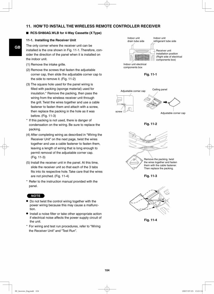
GB
FR
DE
IT
PT
GR
ES
104
11. HOW TO INSTALL THE WIRELESS REMOTE CONTROLLER RECEIVER
■ RCS-SH80AG.WLB for 4-Way Cassette (X Type)
11-1. Installing the Receiver Unit
The only corner where the receiver unit can be installed is the one shown in Fig. 11-1. Therefore, con-sider the direction of the panel when it is installed on the indoor unit.
(1) Remove the intake grille.
(2) Remove the screws that fasten the adjustable corner cap, then slide the adjustable corner cap to the side to remove it. (Fig. 11-2)
(3) The square hole used for the panel wiring is filled with packing (sponge material) used for insulation.* Remove the packing, then pass the wiring from the wireless receiver unit through the grill. Twist the wires together and use a cable fastener to fasten them and attach with a screw, then replace the packing in the hole as it was before. (Fig. 11-3)
* If this packing is not used, there is danger of condensation on the wiring. Be sure to replace the packing.
(4) After completing wiring as described in “Wiring the Receiver Unit” on the next page, twist the wires together and use a cable fastener to fasten them, leaving a length of wiring that is long enough to permit removal of the adjustable corner cap. (Fig. 11-3)
(5) Install the receiver unit in the panel. At this time, slide the receiver unit so that each of the 3 tabs fits into its respective hole. Take care that the wires are not pinched. (Fig. 11-4)
* Refer to the instruction manual provided with the panel.
NOTE
● Do not twist the control wiring together with the power wiring because this may cause a malfunc-tion.
● Install a noise filter or take other appropriate action if electrical noise affects the power supply circuit of the unit.
* For wiring and test run procedures, refer to “Wiring the Receiver Unit” and “Test Run”.
Indoor unit refrigerant tube side
Indoor unit drain tube side
Receiver unit installation position(Right side of electrical components box)
Indoor unit electrical components box
Fig. 11-1
Ceiling panel
screw
Adjustable corner cap
Adjustable corner cap
Fig. 11-2
Remove the packing, twist the wires together and fasten them with the cable fastener. Then replace the packing.
Fig. 11-3
Fig. 11-4
DC_Inverter_Eng.indd 104DC_Inverter_Eng.indd 104 2007/07/25 13:21:542007/07/25 13:21:54
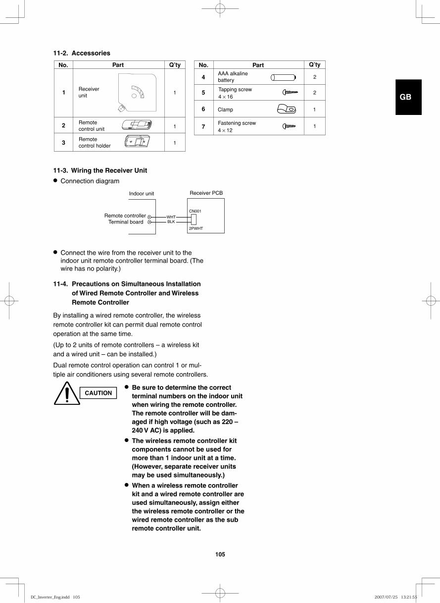
GB
FR
DE
IT
PT
GR
ES
105
11-2. Accessories
11-3. Wiring the Receiver Unit
● Connect the wire from the receiver unit to the indoor unit remote controller terminal board. (The wire has no polarity.)
11-4. Precautions on Simultaneous Installation of Wired Remote Controller and Wireless Remote Controller
By installing a wired remote controller, the wireless remote controller kit can permit dual remote control operation at the same time.
(Up to 2 units of remote controllers – a wireless kit and a wired unit – can be installed.)
Dual remote control operation can control 1 or mul-tiple air conditioners using several remote controllers.
1 1
2 1
3 1
4
6
7
5
Fastening screw4 × 12
Remote control unit
Remote control holder
Part Q’ty Part Q’ty
AAA alkalinebattery
Receiverunit
Tapping screw4 × 16
Clamp
No.No.
2
2
1
1
2PWHT
CN001
WHTBLK
Indoor unit Receiver PCB
Remote controller Terminal board
CAUTION● Be sure to determine the correct
terminal numbers on the indoor unit when wiring the remote controller. The remote controller will be dam-aged if high voltage (such as 220 – 240 V AC) is applied.
● The wireless remote controller kit components cannot be used for more than 1 indoor unit at a time. (However, separate receiver units may be used simultaneously.)
● When a wireless remote controller kit and a wired remote controller are used simultaneously, assign either the wireless remote controller or the wired remote controller as the sub remote controller unit.
● Connection diagram
DC_Inverter_Eng.indd 105DC_Inverter_Eng.indd 105 2007/07/25 13:21:552007/07/25 13:21:55
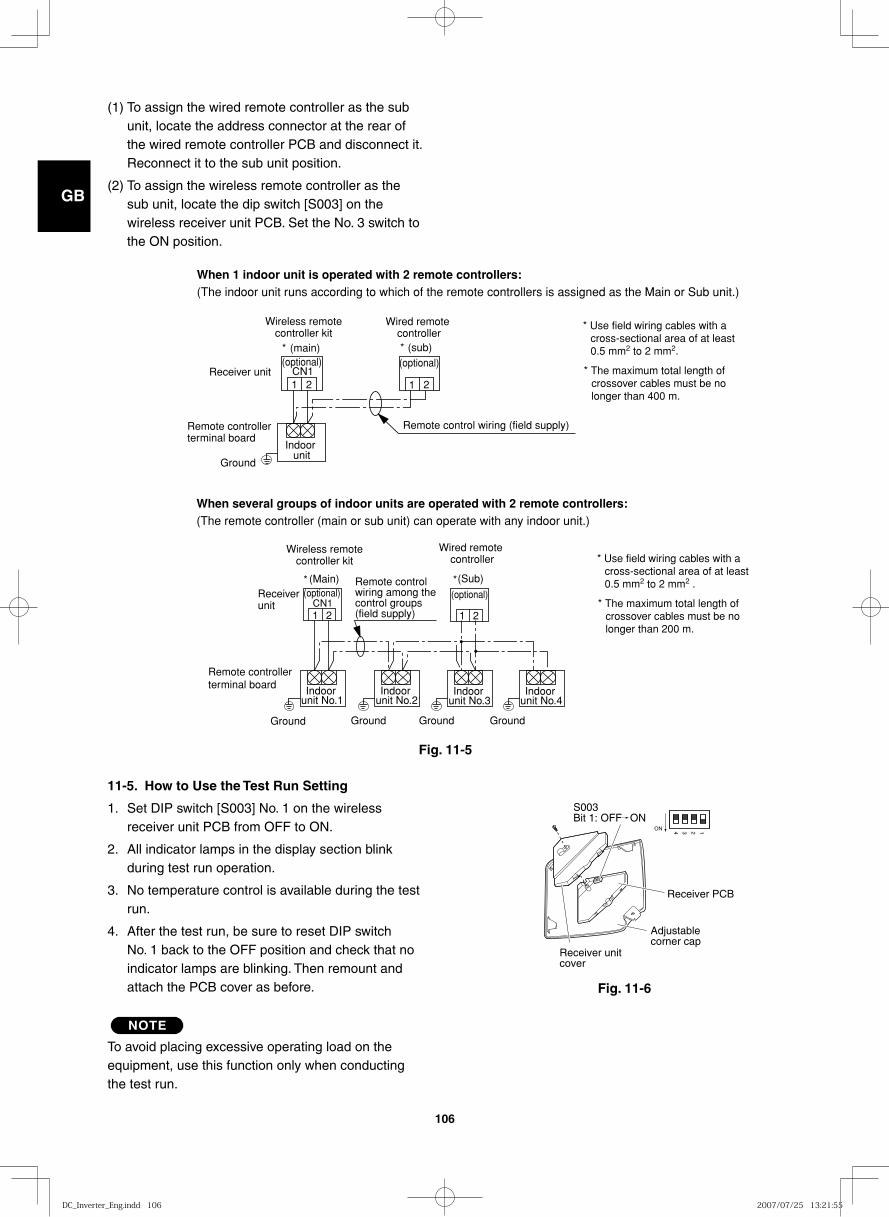
GB
FR
DE
IT
PT
GR
ES
106
CN1(optional)(optional)
1 21 2
Indoor unit
(sub)(main)
Receiver unit
Remote controller terminal board
Ground
Wireless remote controller kit
Wired remote controller
Remote control wiring (field supply)
When 1 indoor unit is operated with 2 remote controllers: (The indoor unit runs according to which of the remote controllers is assigned as the Main or Sub unit.)
* *
* Use field wiring cables with a cross-sectional area of at least 0.5 mm2 to 2 mm2.
* The maximum total length of crossover cables must be no longer than 400 m.
CN1(optional)
1 21 2
(optional)
Indoor unit No.1
Indoor unit No.2
Indoor unit No.3
Indoor unit No.4
Receiver unit
(Main) (Sub)
Remote controller terminal board
When several groups of indoor units are operated with 2 remote controllers: (The remote controller (main or sub unit) can operate with any indoor unit.)
Wireless remote controller kit
Wired remote controller
Remote control wiring among the control groups(field supply)
* Use field wiring cables with a cross-sectional area of at least 0.5 mm2 to 2 mm2 .
* The maximum total length of crossover cables must be no longer than 200 m.
**
Ground Ground Ground Ground
Fig. 11-6
Fig. 11-5
(1) To assign the wired remote controller as the sub unit, locate the address connector at the rear of the wired remote controller PCB and disconnect it. Reconnect it to the sub unit position.
(2) To assign the wireless remote controller as the sub unit, locate the dip switch [S003] on the wireless receiver unit PCB. Set the No. 3 switch to the ON position.
11-5. How to Use the Test Run Setting
1. Set DIP switch [S003] No. 1 on the wireless receiver unit PCB from OFF to ON.
2. All indicator lamps in the display section blink during test run operation.
3. No temperature control is available during the test run.
4. After the test run, be sure to reset DIP switch No. 1 back to the OFF position and check that no indicator lamps are blinking. Then remount and attach the PCB cover as before.
NOTE
To avoid placing excessive operating load on the equipment, use this function only when conducting the test run.
Receiver PCB
Receiver unitcover
ON 1234
Adjustable corner cap
S003Bit 1: OFF ON
DC_Inverter_Eng.indd 106DC_Inverter_Eng.indd 106 2007/07/25 13:21:552007/07/25 13:21:55
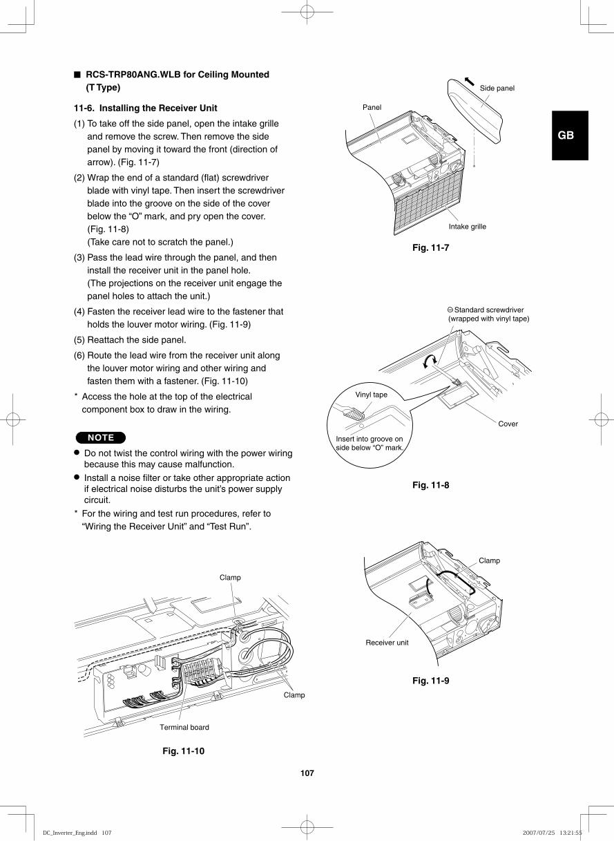
GB
FR
DE
IT
PT
GR
ES
107
■ RCS-TRP80ANG.WLB for Ceiling Mounted (T Type)
11-6. Installing the Receiver Unit
(1) To take off the side panel, open the intake grille and remove the screw. Then remove the side panel by moving it toward the front (direction of arrow). (Fig. 11-7)
(2) Wrap the end of a standard (flat) screwdriver blade with vinyl tape. Then insert the screwdriver blade into the groove on the side of the cover below the “O” mark, and pry open the cover. (Fig. 11-8) (Take care not to scratch the panel.)
(3) Pass the lead wire through the panel, and then install the receiver unit in the panel hole. (The projections on the receiver unit engage the panel holes to attach the unit.)
(4) Fasten the receiver lead wire to the fastener that holds the louver motor wiring. (Fig. 11-9)
(5) Reattach the side panel.
(6) Route the lead wire from the receiver unit along the louver motor wiring and other wiring and fasten them with a fastener. (Fig. 11-10)
* Access the hole at the top of the electrical component box to draw in the wiring.
NOTE
● Do not twist the control wiring with the power wiring because this may cause malfunction.
● Install a noise filter or take other appropriate action if electrical noise disturbs the unit’s power supply circuit.
* For the wiring and test run procedures, refer to “Wiring the Receiver Unit” and “Test Run”.
Fig. 11-7
Panel
Intake grille
Side panel
Fig. 11-8
Insert into groove on side below “O” mark.
Vinyl tape
Standard screwdriver (wrapped with vinyl tape)
Cover
Fig. 11-9
Receiver unit
Clamp
Fig. 11-10
Terminal board
Clamp
Clamp
DC_Inverter_Eng.indd 107DC_Inverter_Eng.indd 107 2007/07/25 13:21:552007/07/25 13:21:55
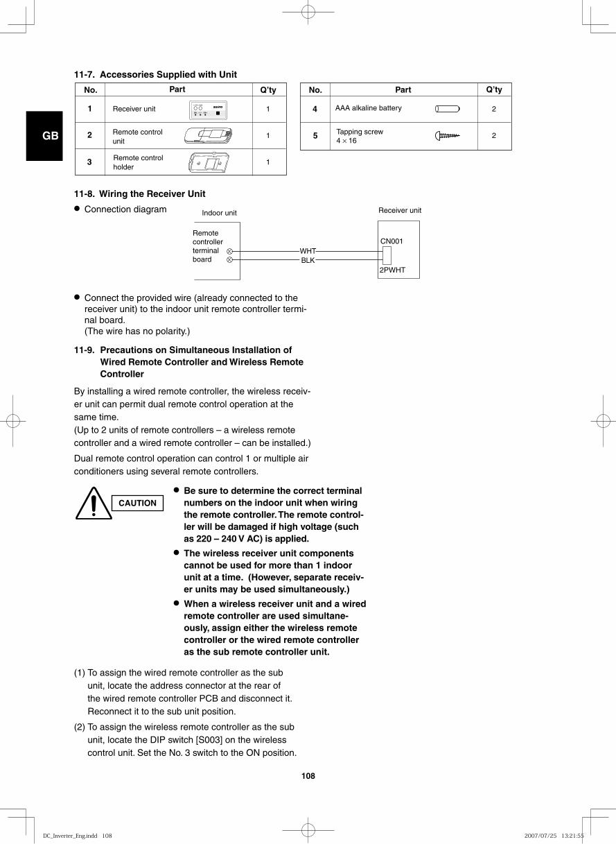
GB
FR
DE
IT
PT
GR
ES
108
11-7. Accessories Supplied with Unit
11-8. Wiring the Receiver Unit
● Connect the provided wire (already connected to the receiver unit) to the indoor unit remote controller termi-nal board. (The wire has no polarity.)
11-9. Precautions on Simultaneous Installation of Wired Remote Controller and Wireless Remote Controller
By installing a wired remote controller, the wireless receiv-er unit can permit dual remote control operation at the same time.(Up to 2 units of remote controllers – a wireless remote controller and a wired remote controller – can be installed.)
Dual remote control operation can control 1 or multiple air conditioners using several remote controllers.
CN001
2PWHT
WHTBLK
Indoor unit Receiver unit
Remote controller terminal board
CAUTION
● Be sure to determine the correct terminal numbers on the indoor unit when wiring the remote controller. The remote control-ler will be damaged if high voltage (such as 220 – 240 V AC) is applied.
● The wireless receiver unit components cannot be used for more than 1 indoor unit at a time. (However, separate receiv-er units may be used simultaneously.)
● When a wireless receiver unit and a wired remote controller are used simultane-ously, assign either the wireless remote controller or the wired remote controller as the sub remote controller unit.
● Connection diagram
1
1
1
2
2
Receiver unit AAA alkaline battery
Remote control holder
Tapping screw4 × 16
4
5
No. Q’ty No. Part Q’ty
1
2
3
Remote controlunit
Part
(1) To assign the wired remote controller as the sub unit, locate the address connector at the rear of the wired remote controller PCB and disconnect it. Reconnect it to the sub unit position.
(2) To assign the wireless remote controller as the sub unit, locate the DIP switch [S003] on the wireless control unit. Set the No. 3 switch to the ON position.
DC_Inverter_Eng.indd 108DC_Inverter_Eng.indd 108 2007/07/25 13:21:552007/07/25 13:21:55
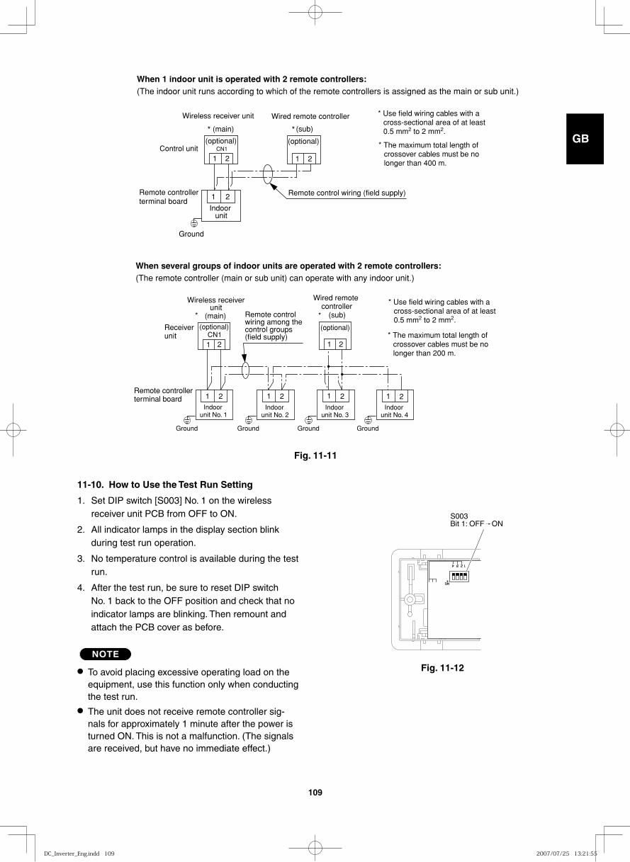
GB
FR
DE
IT
PT
GR
ES
109
CN1
1 21 2
1 2
(main) (sub)
Indoor unit
Control unit
Remote controller terminal board
Ground
Remote control wiring (field supply)
(optional) (optional)
Wireless receiver unit Wired remote controller
When 1 indoor unit is operated with 2 remote controllers: (The indoor unit runs according to which of the remote controllers is assigned as the main or sub unit.)
* Use field wiring cables with a cross-sectional area of at least 0.5 mm2 to 2 mm2.
* The maximum total length of crossover cables must be no longer than 400 m.
**
CN1(optional)
1 2 2 1 2 1 2
1 21 2
(optional)
1Indoor
unit No. 1
Receiver unit
Ground
Remote controller terminal board
Indoor unit No. 2
Indoor unit No. 3
Indoor unit No. 4
(main) (sub)Remote control wiring among the control groups(field supply)
Wired remote controller
When several groups of indoor units are operated with 2 remote controllers: (The remote controller (main or sub unit) can operate with any indoor unit.)
* Use field wiring cables with a cross-sectional area of at least 0.5 mm2 to 2 mm2.
* The maximum total length of crossover cables must be no longer than 200 m.
* *
Wireless receiver unit
Ground Ground Ground
Fig. 11-11
Fig. 11-12
11-10. How to Use the Test Run Setting
1. Set DIP switch [S003] No. 1 on the wireless receiver unit PCB from OFF to ON.
2. All indicator lamps in the display section blink during test run operation.
3. No temperature control is available during the test run.
4. After the test run, be sure to reset DIP switch No. 1 back to the OFF position and check that no indicator lamps are blinking. Then remount and attach the PCB cover as before.
NOTE
● To avoid placing excessive operating load on the equipment, use this function only when conducting the test run.
● The unit does not receive remote controller sig-nals for approximately 1 minute after the power is turned ON. This is not a malfunction. (The signals are received, but have no immediate effect.)
S003Bit 1: OFF ON
DC_Inverter_Eng.indd 109DC_Inverter_Eng.indd 109 2007/07/25 13:21:552007/07/25 13:21:55
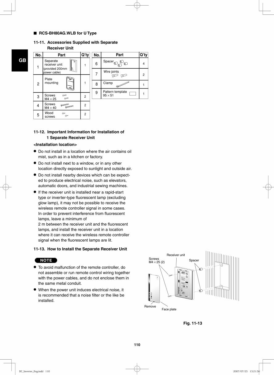
GB
FR
DE
IT
PT
GR
ES
110
■ RCS-BH80AG.WLB for U Type
11-11. Accessories Supplied with Separate Receiver Unit
11-12. Important Information for Installation of 1 Separate Receiver Unit
<Installation location>
● Do not install in a location where the air contains oil mist, such as in a kitchen or factory.
● Do not install next to a window, or in any other location directly exposed to sunlight and outside air.
● Do not install nearby devices which can be expect-ed to produce electrical noise, such as elevators, automatic doors, and industrial sewing machines.
● If the receiver unit is installed near a rapid-start type or inverter-type fluorescent lamp (excluding glow lamp), it may not be possible to receive the wireless remote controller signal in some cases. In order to prevent interference from fluorescent lamps, leave a minimum of 2 m between the receiver unit and the fluorescent lamps, and install the receiver unit in a location where it can receive the wireless remote controller signal when the fluorescent lamps are lit.
11-13. How to Install the Separate Receiver Unit
NOTE
● To avoid malfunction of the remote controller, do not assemble or run remote control wiring together with the power cables, and do not enclose them in the same metal conduit.
● When the power unit induces electrical noise, it is recommended that a noise filter or the like be installed.
Fig. 11-13
1 32
4 65
Face plateRemove
Screws M4 × 25 (2)
Receiver unit
Spacer
2
(provided 200mm power cable)
Plate mounting
ScrewsM4 × 25
ScrewsM4 × 40
Woodscrews
1
2
3
4
5
No. Part Q’ty No.
6
7
8
9
1
1
2
Part Q’ty
4
2
1
1
Separate receiver unit
Spacer
Wire joints
Clamp
Pattern template95 × 512
DC_Inverter_Eng.indd 110DC_Inverter_Eng.indd 110 2007/07/25 13:21:562007/07/25 13:21:56
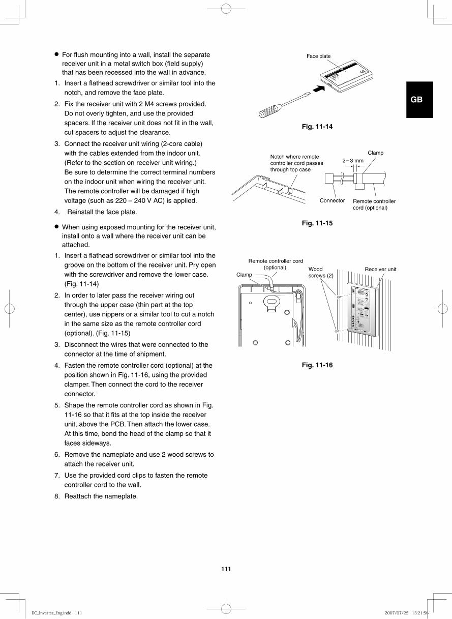
GB
FR
DE
IT
PT
GR
ES
111
Fig. 11-14
Fig. 11-15
Fig. 11-16
● For flush mounting into a wall, install the separate receiver unit in a metal switch box (field supply) that has been recessed into the wall in advance.
1. Insert a flathead screwdriver or similar tool into the notch, and remove the face plate.
2. Fix the receiver unit with 2 M4 screws provided. Do not overly tighten, and use the provided spacers. If the receiver unit does not fit in the wall, cut spacers to adjust the clearance.
3. Connect the receiver unit wiring (2-core cable) with the cables extended from the indoor unit. (Refer to the section on receiver unit wiring.) Be sure to determine the correct terminal numbers on the indoor unit when wiring the receiver unit. The remote controller will be damaged if high voltage (such as 220 – 240 V AC) is applied.
4. Reinstall the face plate.
● When using exposed mounting for the receiver unit, install onto a wall where the receiver unit can be attached.
1. Insert a flathead screwdriver or similar tool into the groove on the bottom of the receiver unit. Pry open with the screwdriver and remove the lower case. (Fig. 11-14)
2. In order to later pass the receiver wiring out through the upper case (thin part at the top center), use nippers or a similar tool to cut a notch in the same size as the remote controller cord (optional). (Fig. 11-15)
3. Disconnect the wires that were connected to the connector at the time of shipment.
4. Fasten the remote controller cord (optional) at the position shown in Fig. 11-16, using the provided clamper. Then connect the cord to the receiver connector.
5. Shape the remote controller cord as shown in Fig. 11-16 so that it fits at the top inside the receiver unit, above the PCB. Then attach the lower case. At this time, bend the head of the clamp so that it faces sideways.
6. Remove the nameplate and use 2 wood screws to attach the receiver unit.
7. Use the provided cord clips to fasten the remote controller cord to the wall.
8. Reattach the nameplate.
Face plate
Notch where remote controller cord passes through top case
Remote controller cord (optional)
Connector
Clamp2 3 mm
1 32
4 65
Remote controller cord (optional) Receiver unit
ClampWood screws (2)
DC_Inverter_Eng.indd 111DC_Inverter_Eng.indd 111 2007/07/25 13:21:562007/07/25 13:21:56
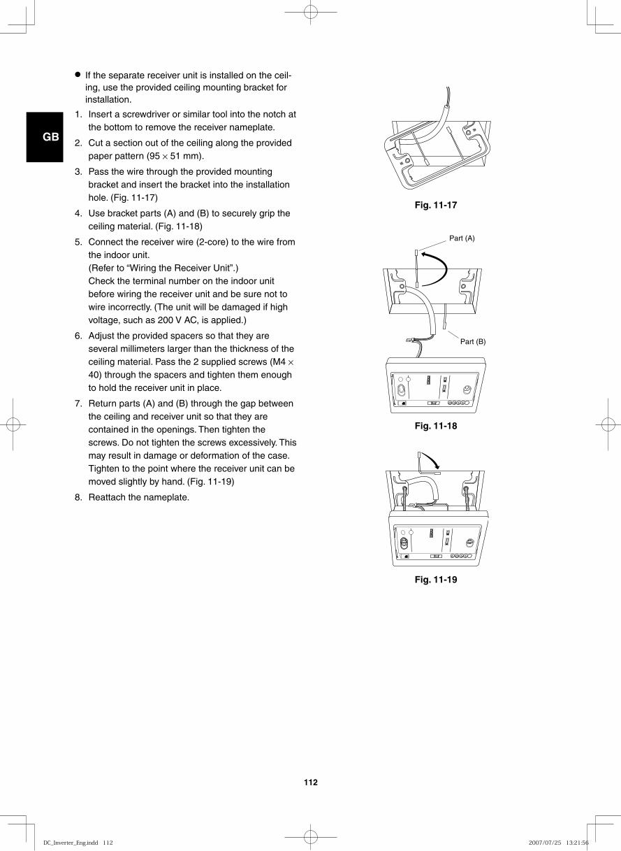
GB
FR
DE
IT
PT
GR
ES
112
● If the separate receiver unit is installed on the ceil-ing, use the provided ceiling mounting bracket for installation.
1. Insert a screwdriver or similar tool into the notch at the bottom to remove the receiver nameplate.
2. Cut a section out of the ceiling along the provided paper pattern (95 × 51 mm).
3. Pass the wire through the provided mounting bracket and insert the bracket into the installation hole. (Fig. 11-17)
4. Use bracket parts (A) and (B) to securely grip the ceiling material. (Fig. 11-18)
5. Connect the receiver wire (2-core) to the wire from the indoor unit. (Refer to “Wiring the Receiver Unit”.) Check the terminal number on the indoor unit before wiring the receiver unit and be sure not to wire incorrectly. (The unit will be damaged if high voltage, such as 200 V AC, is applied.)
6. Adjust the provided spacers so that they are several millimeters larger than the thickness of the ceiling material. Pass the 2 supplied screws (M4 × 40) through the spacers and tighten them enough to hold the receiver unit in place.
7. Return parts (A) and (B) through the gap between the ceiling and receiver unit so that they are contained in the openings. Then tighten the screws. Do not tighten the screws excessively. This may result in damage or deformation of the case. Tighten to the point where the receiver unit can be moved slightly by hand. (Fig. 11-19)
8. Reattach the nameplate.
Fig. 11-17
Part (B)
Part (A)
Fig. 11-18
Fig. 11-19
DC_Inverter_Eng.indd 112DC_Inverter_Eng.indd 112 2007/07/25 13:21:562007/07/25 13:21:56
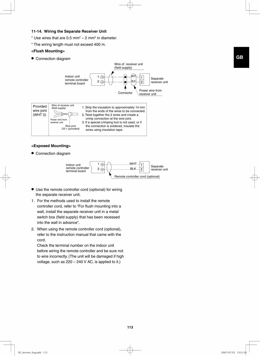
GB
FR
DE
IT
PT
GR
ES
113
11-14. Wiring the Separate Receiver Unit
* Use wires that are 0.5 mm2 – 2 mm2 in diameter.
* The wiring length must not exceed 400 m.
<Flush Mounting>
● Connection diagramWire of receiver unit (field supply)
Power wire from receiver unit
Separate receiver unit
Connector
Indoor unitremote controller terminal board
1
212
WHT
BLK
Wire of receiver unit (field supply)
Power wire from receiver unit
1. Strip the insulation to approximately 14 mm from the ends of the wires to be connected.
2. Twist together the 2 wires and create a crimp connection at the wire joint.
3. If a special crimping tool is not used, or if the connection is soldered, insulate the wires using insulation tape.
Provided wire joint(WHT 2)
Wire jointCE-1 (provided)
Remote controller cord (optional)
Separate receiver unit
Indoor unitremote controllerterminal board
1
2
WHT
BLK12
<Exposed Mounting>
● Connection diagram
● Use the remote controller cord (optional) for wiring the separate receiver unit.
1. For the methods used to install the remote controller cord, refer to “For flush mounting into a wall, install the separate receiver unit in a metal switch box (field supply) that has been recessed into the wall in advance”.
2. When using the remote controller cord (optional), refer to the instruction manual that came with the cord. Check the terminal number on the indoor unit before wiring the remote controller and be sure not to wire incorrectly. (The unit will be damaged if high voltage, such as 220 – 240 V AC, is applied to it.)
DC_Inverter_Eng.indd 113DC_Inverter_Eng.indd 113 2007/07/25 13:21:562007/07/25 13:21:56
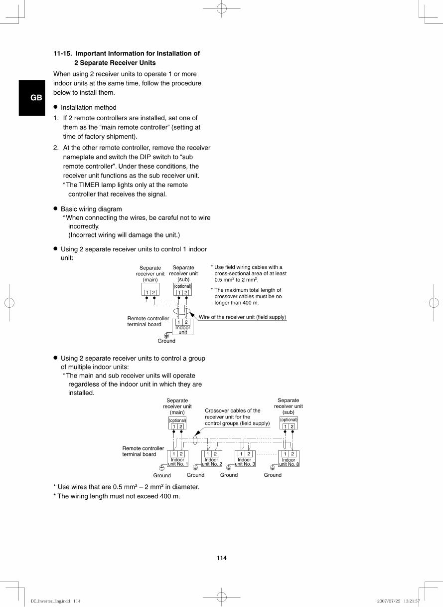
GB
FR
DE
IT
PT
GR
ES
114
11-15. Important Information for Installation of 2 Separate Receiver Units
When using 2 receiver units to operate 1 or more indoor units at the same time, follow the procedure below to install them.
● Installation method
1. If 2 remote controllers are installed, set one of them as the “main remote controller” (setting at time of factory shipment).
2. At the other remote controller, remove the receiver nameplate and switch the DIP switch to “sub remote controller”. Under these conditions, the receiver unit functions as the sub receiver unit.* The TIMER lamp lights only at the remote
controller that receives the signal.
● Basic wiring diagram* When connecting the wires, be careful not to wire
incorrectly. (Incorrect wiring will damage the unit.)
● Using 2 separate receiver units to control 1 indoor unit:
● Using 2 separate receiver units to control a group of multiple indoor units:* The main and sub receiver units will operate
regardless of the indoor unit in which they are installed.
* Use wires that are 0.5 mm2 – 2 mm2 in diameter.* The wiring length must not exceed 400 m.
Separate receiver unit
(main)
Separate receiver unit
(sub)(optional)
Remote controller terminal board
Wire of the receiver unit (field supply)
Indoor unit
1 2
1 221
* Use field wiring cables with a cross-sectional area of at least 0.5 mm2 to 2 mm2.
* The maximum total length of crossover cables must be no longer than 400 m.
Ground
1 2
1 2
1 2
1 2
1 21 2Indoor
unit No. 1Indoor
unit No. 2Indoor
unit No. 3Indoor
unit No. 8
Remote controller terminal board
Separate receiver unit
(main)
(optional)
Separate receiver unit
(sub)(optional)
Crossover cables of the receiver unit for the control groups (field supply)
Ground Ground Ground Ground
DC_Inverter_Eng.indd 114DC_Inverter_Eng.indd 114 2007/07/25 13:21:572007/07/25 13:21:57
GB
FR
DE
IT
PT
GR
ES
115
11-16. Test Run Setting
1. Remove the receiver unit face plate, and set the DIP switch to “Test Run – ON” position.
2. Run the air conditioner using the wireless remote controller by pressing the “ON/OFF” button.
● All LED (“RUN”, “TIMER” and “STANDBY”) blink during test run operation.
● No temperature control is effective with the wire-less remote controller in the “Test Run – ON” posi-tion. To avoid mechanical strain on the air conditioner, do not use this mode except for conducting a test run.
3. Select any one of the operation modes HEAT, COOL or FAN for the test run. * The outdoor unit will not start running for about 3
minutes after the power ON button is pressed.
4. After the test run operation, stop the air conditioner using the wireless remote controller, and then reset the DIP switch in the receiver unit as it was before. (To prevent constant test running of the air conditioner, the receiver unit has a 60-minute off-timer function.)
DC_Inverter_Eng.indd 115DC_Inverter_Eng.indd 115 2007/07/25 13:21:572007/07/25 13:21:57
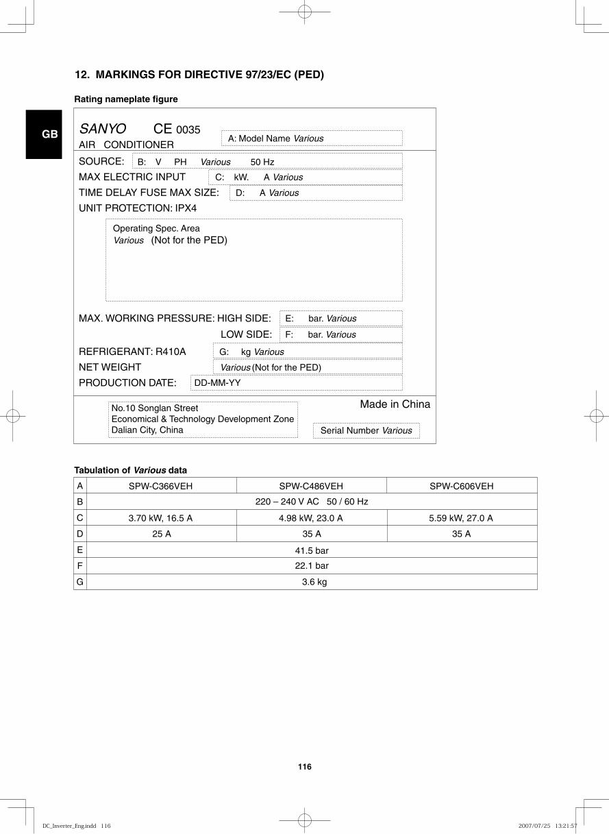
GB
FR
DE
IT
PT
GR
ES
116
12. MARKINGS FOR DIRECTIVE 97/23/EC (PED)
Rating nameplate figure
Tabulation of Various data
AIR CONDITIONER
SOURCE:
MAX ELECTRIC INPUT
MAX . W ORKING PRESSURE : HIGH SIDE :
L O W SIDE :
C : k W . A Various
D : A VariousTIME DEL A Y FUSE MAX SIZE :
UNIT P R O TECTION : IPX 4
REFRIGERAN T : R410 A G : kg Various
Various (Not for the PED)
DD-MM-YY
Made in China
Se r ial Number Various
No.10 Songlan Street Economical & Technology Development Zone Dalian City, China
NET WEIGHT
P R ODUCTION D A TE :
A : Model Name Various
E : ba r . Various
F : ba r . Various
Ope r ating Spec . Are a Various (Not f or the PED )
B : V PH Various 50 Hz
SANYO CE 0035
A
C
220 – 240 V AC 50 / 60 Hz
41.5 bar
22.1 bar
25 A 35 A
3.70 kW, 16.5 A 4.98 kW, 23.0 A 5.59 kW, 27.0 A
35 A
3.6 kg
D
F
E
G
B
SPW-C366VEH SPW-C486VEH SPW-C606VEH
DC_Inverter_Eng.indd 116DC_Inverter_Eng.indd 116 2007/07/25 13:21:572007/07/25 13:21:57
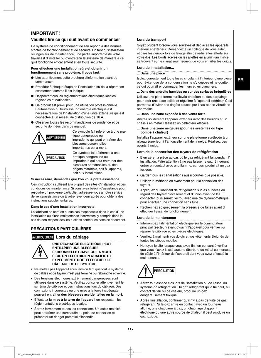
GB
FR
DE
IT
PT
GR
ES
117117
IMPOR TANT!Veuillez lire ce qui suit avant de com men cerCe sys tè me de condi tion ne ment de l’air répond à des nor mes stric tes de fonc tion ne ment et de sécu ri té. En tant qu’instal la teur ou ingé nieur de main te nan ce, une par tie impor tan te de votre tra vail est d’instal ler ou d’entre te nir le sys tè me de maniè re à ce qu’il fonc tion ne effi ca ce ment et en toute sécu ri té.
Pour effec tuer une instal la tion sûre et obte nir un fonc tion ne ment sans pro blè me, il vous faut:
● Lire atten ti ve ment cette bro chu re d’infor ma tion avant de com men cer.
● Procéder à cha que étape de l’instal la tion ou de la répa ra tion exac te ment comme il est indi qué.
● Respecter tous les régle men ta tions élec tri ques loca les, régio na les et natio na les.
● Ce produit est prévu pour une utilisation professionnelle. L’autorisation du fournisseur d’énergie électrique est
nécessaire lors de l’installation d’une unité extérieure qui est connectée à un réseau de distribution de 16 A.
● Observer tou tes les recom man da tions de pru den ce et de sécu ri té don nées dans ce manuel.
Ce sym bo le fait réfé ren ce à une pra-ti que dan ge reu se ou impru den te qui peut entraî ner des bles su res per son nel les impor tan tes ou la mort.
Ce sym bo le fait réfé ren ce à une pra ti que dan ge reu se ou impru den te qui peut entraî ner des bles su res per son nel les ou des dégâts maté riels, soit à l’appa reil, soit aux instal la tions.
Si néces sai re, deman dez que l’on vous prête assis tan ce
Ces instruc tions suf fi sent à la plu part des sites d’instal la tion et des condi tions de main te nan ce. Si vous avez besoin d’assis tan ce pour résou dre un pro blè me par ti cu lier, adres sez-vous à notre ser vi ce de vente/assis tan ce ou à votre reven deur agréé pour obte nir des instruc tions sup plé men tai res.
Dans le cas d’une instal la tion incor rec te
Le fabri cant ne sera en aucun cas res pon sa ble dans le cas d’une instal la tion ou d’une main te nan ce incor rec tes, y com pris dans le cas de non-res pect des instruc tions conte nues dans ce docu ment.
PRÉ CAU TIONS PARTICULIÈRES
AVERTISSEMENT Lors du câbla ge
UNE DÉCHAR GE ÉLEC TRI QUE PEUT ENTRAÎNER UNE BLES SU RE PER SON NEL LE GRAVE OU LA MORT. SEUL UN ÉLEC TRI CIEN QUA LI FIÉ ET EXPÉ RI MEN TÉ DOIT EFFEC TUER LE CÂBLAGE DE CE SYSTÈME.
• Ne met tez pas l’appa reil sous ten sion tant que tout le sys tè me de câbles et de tuyaux n’est pas ter mi né ou rebran ché et véri fié.
• Des ten sions élec tri ques extrê me ment dan ge reu ses sont uti li sées dans ce sys tè me. Veuillez consul ter atten ti ve ment le sché ma de câbla ge et ces instruc tions lors du câbla ge. Des connexions incor rec tes ou une mise à la terre inadé qua te peu vent entraî ner des bles su res acci den tel les ou la mort.
• Effectuez la mise à la terre de l’appa reil en res pec tant les régle men ta tions élec tri ques loca les.
• Serrez fer me ment tou tes les connexions. Un câble mal fixé peut entraî ner une sur chauf fe au point de connexion et pré sen ter un dan ger poten tiel d’incen die.
Lors du trans port
Soyez pru dent lors que vous sou le vez et dépla cez les appa reils inté rieur et exté rieur. Demandez à un col lè gue de vous aider, et pliez les genoux lors du leva ge afin de rédui re les efforts sur votre dos. Les bords acé rés ou les ailet tes en alu mi nium mince se trou vant sur le cli ma ti seur ris quent de vous entailler les doigts.
Lors de l’instal la tion...
... Dans une pièce
Isolez cor rec te ment toute tuyau cir cu lant à l’inté rieur d’une pièce pour évi ter que de la conden sa tion ne s’y dépo se et ne gout te, ce qui pour rait endom ma ger les murs et les plan chers.
... Dans des endroits humi des ou sur des sur fa ces irré gu liè res
Utilisez une plate-forme sur éle vée en béton ou des par paings pour offrir une base soli de et régu liè re à l’appa reil exté rieur. Ceci per met tra d’évi ter des dégâts cau sés par l’eau et des vibra tions anor ma les.
... Dans une zone expo sée à des vents forts
Ancrez soli de ment l’appa reil exté rieur avec des bou lons et un châs sis en métal. Réalisez un déflec teur effi ca ce.
... Dans une zone nei geu se (pour les sys tè mes du type pompe à cha leur)
Installez l’appa reil exté rieur sur une plate-forme sur éle vée à un niveau supé rieur à l’amon cel le ment de la neige. Réalisez des évents à neige.
Lors de la connexion des tuyaux de réfri gé ra tion
• Bien aérer la pièce au cas où le gaz réfrigérant fuit pendant l’installation. Faire attention à ne pas laisser le gaz réfrigérant entrer en contact avec une flamme, car ceci produirait un gaz toxique.
• Garder tous les canalisations aussi courtes que possible.
• Utilisez la métho de en éva se ment pour la connexion des tuyaux.
• Appliquez du lubri fiant de réfri gé ra tion sur les sur fa ces en regard des tuyaux d’éva se ment et d’union avant de les connec ter, puis ser rez l’écrou avec une clé dyna mo mé tri que pour effec tuer une connexion sans fuite.
• Recherchez soi gneu se ment la pré sen ce de fui tes avant d’effec tuer l’essai de fonc tion ne ment.
Lors de la main te nan ce
• Interrompez l’ali men ta tion élec tri que sur le com mu ta teur prin ci pal (sec teur) avant d’ouvrir l’appa reil pour véri fier ou répa rer le câbla ge et les piè ces élec tri ques.
• Veuillez à main te nir vos doigts et vos vête ments éloi gnés de tou tes les piè ces mobi les.
• Nettoyez le site lors que vous avez fini, en pen sant à véri fier que vous n’avez lais sé aucu ne ébar bu re de métal ou mor ceau de câble à l’inté rieur de l’appa reil dont vous avez effec tué la main te nan ce.
• Aérez tout espa ce clos lors de l’instal la tion ou de l’essai du sys tè me de réfri gé ra tion. Du gaz réfri gé rant qui a fui peut, au contact de feu ou de cha leur, pro dui re un gaz dan ge reu se ment toxi que.
• Après l’installation, confirmer qu’il n’y a pas de fuite de gaz réfrigérant. Si le gaz entre en contact avec un fourneau allumé, une chaudière à gaz, un chauffage d’appoint électrique ou une autre source de chaleur, il peut produire un gaz toxique.
AVERTISSEMENT
PRECAUTION
PRECAUTION
DC_Inverter_FR.indd 117DC_Inverter_FR.indd 117 2007/07/25 12:16:022007/07/25 12:16:02
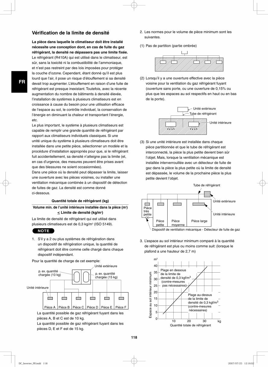
GB
FR
DE
IT
PT
GR
ES
118
2. Les normes pour le volume de pièce minimum sont les suivantes.
(1) Pas de partition (partie ombrée)
(2) Lorsqu’il y a une ouverture effective avec la pièce voisine pour la ventilation du gaz réfrigérant fuyant (ouverture sans porte, ou une ouverture de 0,15% ou plus que les espaces au sol respectifs en haut ou en bas de la porte).
(3) Si une unité intérieure est installée dans chaque pièce partitionnée et que le tube de réfrigérant est interconnecté, la pièce la plus petite devient bien sûr l’objet. Mais, lorsque la ventilation mécanique est installée interverrouillée avec un détecteur de fuite de gaz dans la pièce la plus petite où la limite de densité est dépassée, le volume de la prochaine pièce la plus petite devient l’objet.
3. L’espace au sol intérieur minimum comparé à la quantité de réfrigérant est plus ou moins comme suit: (lorsque le plafond a une hauteur de 2,7 m)
Vérification de la limite de densité
La pièce dans laquelle le climatiseur doit être installé nécessite une conception dont, en cas de fuite du gaz réfrigérant, la densité ne dépassera pas une limite fixée.Le réfrigérant (R410A) qui est utilisé dans le climatiseur, est sûr, sans la toxicité ni la combustibilité de l’ammoniaque, et n’est pas restreint par des lois imposées pour protéger la couche d’ozone. Cependant, étant donné qu’il est plus lourd que l’air, il pose un risque d’étouffement si sa densité devait trop augmenter. L’étouffement en raison d’une fuite de réfrigérant est presque inexistant. Toutefois, avec la récente augmentation du nombre de bâtiments à densité élevée, l’installation de systèmes à plusieurs climatiseurs est en croissance à cause du besoin pour une utilisation efficace de l’espace au sol, le contrôle individuel, la conservation de l’énergie en diminuant la chaleur et transportant l’énergie, etc.Le plus important, le système à plusieurs climatiseurs est capable de remplir une grande quantité de réfrigérant par rapport aux climatiseurs individuels classiques. Si une unité unique du système à plusieurs climatiseurs doit être installée dans une petite pièce, sélectionner un modèle et la procédure d’installation appropriés pour que, si le réfrigérant fuit accidentellement, sa densité n’atteigne pas la limite (et, en cas d’urgence, des mesures peuvent être prises avant que des blessures ne soient occasionnées).Dans une pièce où la densité peut dépasser la limite, laisser une ouverture avec les pièces voisines, ou installer une ventilation mécanique combinée à un dispositif de détection de fuites de gaz. La densité est comme donné ci-dessous.
Quantité totale de réfrigérant (kg)
Volume min. de l’unité intérieure installée dans la pièce (m3)< Limite de densité (kg/m3)
La limite de densité de réfrigérant qui est utilisé dans plusieurs climatiseurs est de 0,3 kg/m3 (ISO 5149).
NOTE
1. S’il y a 2 ou plus systèmes de réfrigération dans un dispositif de réfrigération unique, la quantité de réfrigérant doit être comme celle chargé dans chaque
dispositif indépendant.
Pour la quantité de charge de cet exemple:
La quantité possible de gaz réfrigérant fuyant dans les pièces A, B et C est de 10 kg.La quantité possible de gaz réfrigérant fuyant dans les pièces D, E et F est de 15 kg.
Unité extérieure
Tube de réfrigérant
Unité intérieure
p. ex. quantité chargée (10 kg)
Unité extérieure
Unité intérieure
Pièce A Pièce B Pièce C Pièce D Pièce E Pièce F
p. ex. quantité chargée (15 kg)
Tube de réfrigérant
Unité extérieure
Pièce très petite Unité intérieure
Pièce petite
Piècemoyenne
Pièce large
Dispositif de ventilation mécanique - Détecteur de fuite de gaz
40
35
30
25
20
15
10
5
0 10 20 30
Quantité totale de réfrigérant
Esp
ace
au s
ol in
térie
ur m
inim
um
m 2
kg
Plage en dessous de la limite de densité de 0,3 kgf/m3
(contre-mesures pas nécessaires)
Plage au-dessus de la limite de densité de 0,3 kgf/m3 (contre-mesures nécessaires)
DC_Inverter_FR.indd 118DC_Inverter_FR.indd 118 2007/07/25 12:16:022007/07/25 12:16:02
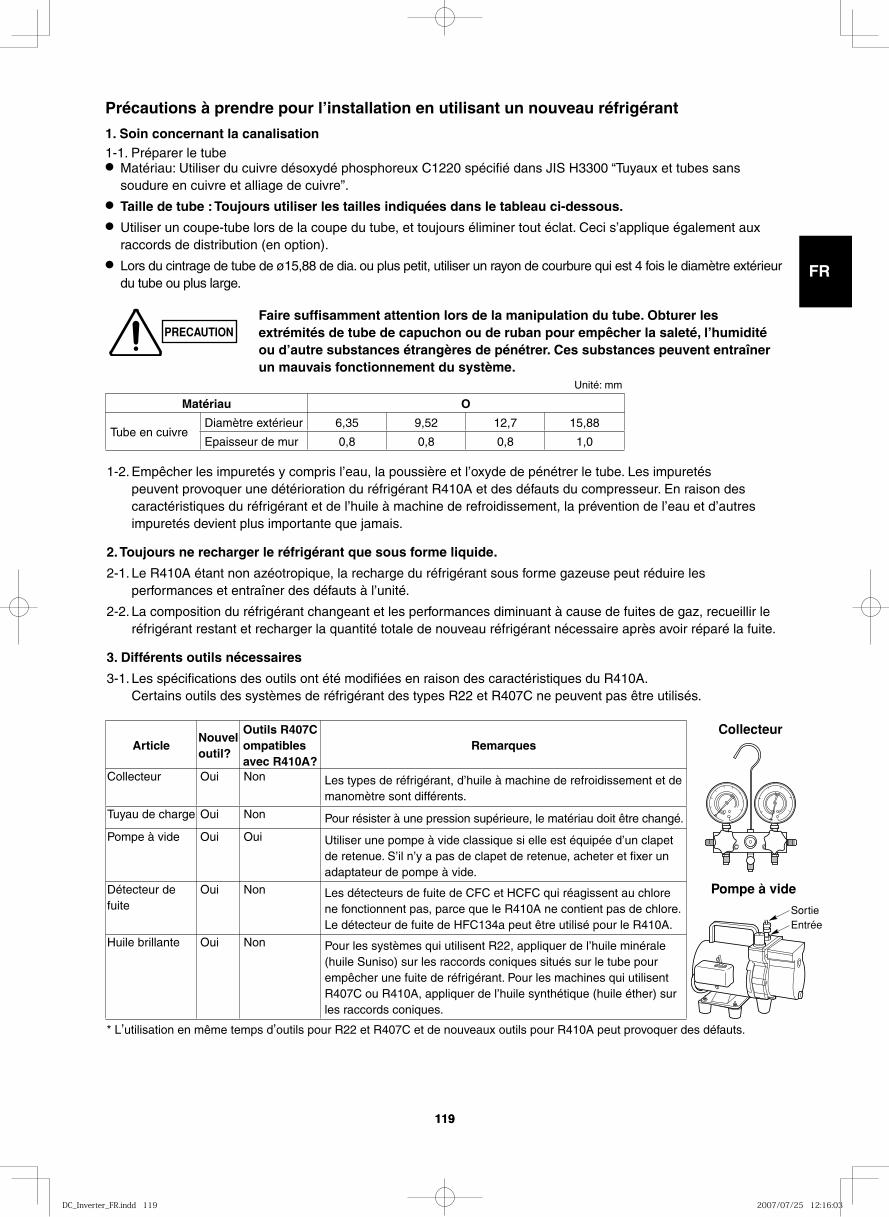
GB
FR
DE
IT
PT
GR
ES
119119
1-2. Empêcher les impuretés y compris l’eau, la poussière et l’oxyde de pénétrer le tube. Les impuretés peuvent provoquer une détérioration du réfrigérant R410A et des défauts du compresseur. En raison des caractéristiques du réfrigérant et de l’huile à machine de refroidissement, la prévention de l’eau et d’autres impuretés devient plus importante que jamais.
2. Toujours ne recharger le réfrigérant que sous forme liquide.
2-1. Le R410A étant non azéotropique, la recharge du réfrigérant sous forme gazeuse peut réduire les performances et entraîner des défauts à l’unité.
2-2. La composition du réfrigérant changeant et les performances diminuant à cause de fuites de gaz, recueillir le réfrigérant restant et recharger la quantité totale de nouveau réfrigérant nécessaire après avoir réparé la fuite.
3. Différents outils nécessaires
3-1. Les spécifications des outils ont été modifiées en raison des caractéristiques du R410A. Certains outils des systèmes de réfrigérant des types R22 et R407C ne peuvent pas être utilisés.
Précautions à prendre pour l’installation en utilisant un nouveau réfrigérant
1. Soin concernant la canalisation1-1. Préparer le tube● Matériau: Utiliser du cuivre désoxydé phosphoreux C1220 spécifié dans JIS H3300 “Tuyaux et tubes sans
soudure en cuivre et alliage de cuivre”.● Taille de tube : Toujours utiliser les tailles indiquées dans le tableau ci-dessous.● Utiliser un coupe-tube lors de la coupe du tube, et toujours éliminer tout éclat. Ceci s’applique également aux
raccords de distribution (en option).● Lors du cintrage de tube de ø15,88 de dia. ou plus petit, utiliser un rayon de courbure qui est 4 fois le diamètre extérieur
du tube ou plus large.
Collecteur
Pompe à vide
SortieEntrée
PRECAUTIONFaire suffisamment attention lors de la manipulation du tube. Obturer les extrémités de tube de capuchon ou de ruban pour empêcher la saleté, l’humidité ou d’autre substances étrangères de pénétrer. Ces substances peuvent entraîner un mauvais fonctionnement du système.
* L’utilisation en même temps d’outils pour R22 et R407C et de nouveaux outils pour R410A peut provoquer des défauts.
Unité: mm
Matériau O
Tube en cuivreDiamètre extérieur 6,35 9,52 12,7 15,88
Epaisseur de mur 0,8 0,8 0,8 1,0
ArticleNouvel outil?
Outils R407C ompatibles avec R410A?
Remarques
Collecteur Oui Non Les types de réfrigérant, d’huile à machine de refroidissement et de manomètre sont différents.
Tuyau de charge Oui Non Pour résister à une pression supérieure, le matériau doit être changé.
Pompe à vide Oui Oui Utiliser une pompe à vide classique si elle est équipée d’un clapet de retenue. S’il n’y a pas de clapet de retenue, acheter et fixer un adaptateur de pompe à vide.
Détecteur de fuite
Oui Non Les détecteurs de fuite de CFC et HCFC qui réagissent au chlore ne fonctionnent pas, parce que le R410A ne contient pas de chlore. Le détecteur de fuite de HFC134a peut être utilisé pour le R410A.
Huile brillante Oui Non Pour les systèmes qui utilisent R22, appliquer de l’huile minérale (huile Suniso) sur les raccords coniques situés sur le tube pour empêcher une fuite de réfrigérant. Pour les machines qui utilisent R407C ou R410A, appliquer de l’huile synthétique (huile éther) sur les raccords coniques.
DC_Inverter_FR.indd 119DC_Inverter_FR.indd 119 2007/07/25 12:16:032007/07/25 12:16:03
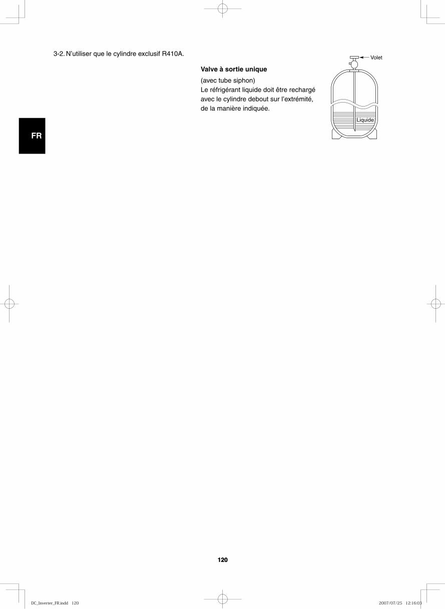
GB
FR
DE
IT
PT
GR
ES
120120
Volet
Liquide
3-2. N’utiliser que le cylindre exclusif R410A.
Valve à sortie unique
(avec tube siphon)Le réfrigérant liquide doit être rechargé avec le cylindre debout sur l’extrémité, de la manière indiquée.
DC_Inverter_FR.indd 120DC_Inverter_FR.indd 120 2007/07/25 12:16:032007/07/25 12:16:03
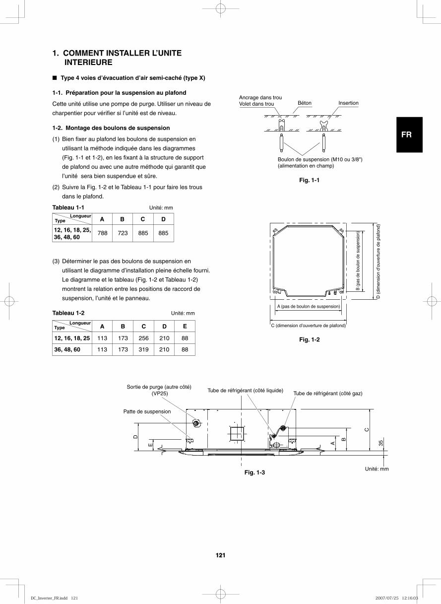
GB
FR
DE
IT
PT
GR
ES
121121
1. COMMENT INSTALLER L’UNITE INTERIEURE
■ Type 4 voies d’évacuation d’air semi-caché (type X)
1-1. Préparation pour la suspension au plafond
Cette unité utilise une pompe de purge. Utiliser un niveau de
charpentier pour vérifier si l’unité est de niveau.
1-2. Montage des boulons de suspension
(1) Bien fixer au plafond les boulons de suspension en
utilisant la méthode indiquée dans les diagrammes
(Fig. 1-1 et 1-2), en les fixant à la structure de support
de plafond ou avec une autre méthode qui garantit que
l’unité sera bien suspendue et sûre.
(2) Suivre la Fig. 1-2 et le Tableau 1-1 pour faire les trous
dans le plafond.
Tableau 1-1 Unité: mm
(3) Déterminer le pas des boulons de suspension en
utilisant le diagramme d’installation pleine échelle fourni.
Le diagramme et le tableau (Fig. 1-2 et Tableau 1-2)
montrent la relation entre les positions de raccord de
suspension, l’unité et le panneau.
Tableau 1-2 Unité: mm
Fig. 1-1
Fig. 1-2
Ancrage dans trouVolet dans trou Béton Insertion
Boulon de suspension (M10 ou 3/8")(alimentation en champ)
Type A B C D
788 723 88588512, 16, 18, 25, 36, 48, 60
Longueur
A B C D
113 173
173
210
210
256
36, 48, 60
12, 16, 18, 25
E
88
88319113
TypeLongueur
D (
dim
ensi
on d
'ouv
ertu
re d
e pl
afon
d)
C (dimension dʼouverture de plafond)
A (pas de boulon de suspension)
B (p
as d
e bo
ulon
de
susp
ensi
on)
E A
B
C
D
35
Patte de suspension
Tube de réfrigérant (côté liquide) Tube de réfrigérant (côté gaz)Sortie de purge (autre côté)
(VP25)
Fig. 1-3Unité: mm
DC_Inverter_FR.indd 121DC_Inverter_FR.indd 121 2007/07/25 12:16:032007/07/25 12:16:03

GB
FR
DE
IT
PT
GR
ES
122122
Fig. 1-4
Fig. 1-5
1-3. Installation de la canalisation de purge
(1) Lors de la mise en place de l’unité dans le plafond,
déterminer le pas des boulons de suspension en
utilisant le diagramme d’installation pleine échelle fourni
(Fig. 1-4).
La canalisation et le câblage doivent être posés dans
le plafond lors de la suspension de l’unité. Si le plafond
est déjà construit, mettre la canalisation et le câblage
en position pour la connexion à l’unité avant de la placer
dans le plafond.
(2) La longueur des boulons de suspension doit être
appropriée pour une distance entre le bas du boulon
et le bas de l’unité supérieure à 15 mm de la manière
indiquée en Fig. 1-4.
(3) Fileter les 3 écrous hexagonaux et 2 rondelles
(fourniture en champ) sur chacun des 4 boulons de
suspension de la manière indiquée en Fig. 1-5. Utiliser
1 écrou et 1 rondelle pour le côté supérieur et 2 écrous
et 1 rondelle pour le côté inférieur pour que l’unité ne
tombe pas des pattes de suspension.
(4) Ajuster pour que la distance entre l’unité et la partie
inférieure du plafond soit de 12 à 17 mm. Serrer les
écrous sur le côté supérieur et le côté inférieur de la
patte de suspension.
(5) Déposer le polyéthylène de protection utilisé pour
protéger les pièces du ventilateur pendant le transport.
Diagramme dʼinstallation pleine échelle (imprimé sur le haut de la boîte)Boulon fourni
Plu
s de
15
mm
12 –
17
mm
12 – 17 (mm)
Ecrous et rondelles (utiliser pour supérieur et inférieur)
Boulon de suspension
Patte de suspension
EncocheEcrou double
DC_Inverter_FR.indd 122DC_Inverter_FR.indd 122 2007/07/25 12:16:032007/07/25 12:16:03
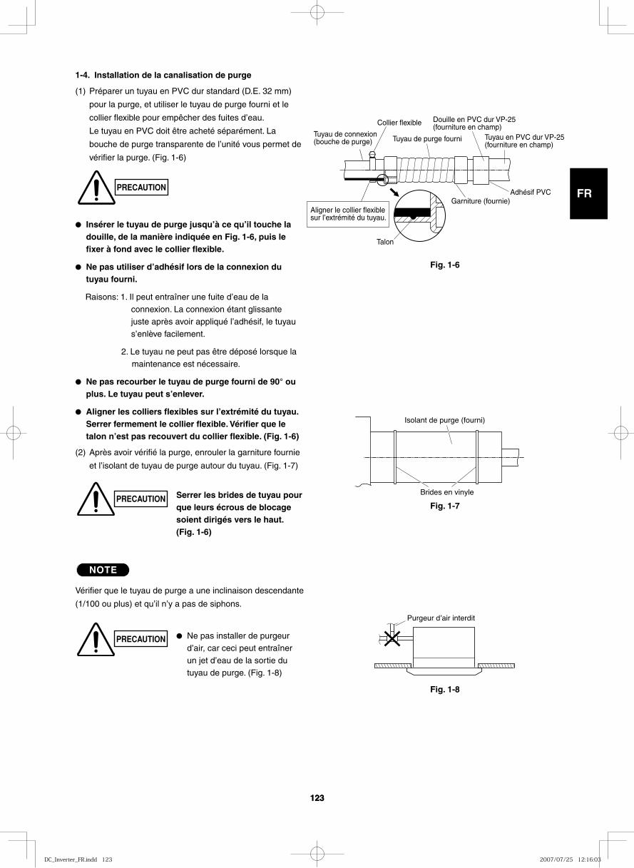
GB
FR
DE
IT
PT
GR
ES
123123
Tuyau de connexion (bouche de purge)
Collier flexible
Tuyau de purge fourni
Douille en PVC dur VP-25(fourniture en champ)
Tuyau en PVC dur VP-25 (fourniture en champ)
Adhésif PVCGarniture (fournie)
Talon
Aligner le collier flexible sur l’extrémité du tuyau.
1-4. Installation de la canalisation de purge
(1) Préparer un tuyau en PVC dur standard (D.E. 32 mm)
pour la purge, et utiliser le tuyau de purge fourni et le
collier flexible pour empêcher des fuites d’eau.
Le tuyau en PVC doit être acheté séparément. La
bouche de purge transparente de l’unité vous permet de
vérifier la purge. (Fig. 1-6)
● Insérer le tuyau de purge jusqu’à ce qu’il touche la douille, de la manière indiquée en Fig. 1-6, puis le fixer à fond avec le collier flexible.
● Ne pas utiliser d’adhésif lors de la connexion du tuyau fourni.
Raisons: 1. Il peut entraîner une fuite d’eau de la connexion. La connexion étant glissante juste après avoir appliqué l’adhésif, le tuyau s’enlève facilement.
2. Le tuyau ne peut pas être déposé lorsque la maintenance est nécessaire.
● Ne pas recourber le tuyau de purge fourni de 90° ou plus. Le tuyau peut s’enlever.
● Aligner les colliers flexibles sur l’extrémité du tuyau. Serrer fermement le collier flexible. Vérifier que le talon n’est pas recouvert du collier flexible. (Fig. 1-6)
(2) Après avoir vérifié la purge, enrouler la garniture fournie
et l’isolant de tuyau de purge autour du tuyau. (Fig. 1-7)
NOTE
Vérifier que le tuyau de purge a une inclinaison descendante
(1/100 ou plus) et qu’il n’y a pas de siphons.
Fig. 1-6
Fig. 1-7
Fig. 1-8
Brides en vinyle
Isolant de purge (fourni)
Purgeur dʼair interdit
PRECAUTION
PRECAUTION Serrer les brides de tuyau pour que leurs écrous de blocage soient dirigés vers le haut. (Fig. 1-6)
PRECAUTION ● Ne pas installer de purgeur d’air, car ceci peut entraîner un jet d’eau de la sortie du tuyau de purge. (Fig. 1-8)
DC_Inverter_FR.indd 123DC_Inverter_FR.indd 123 2007/07/25 12:16:032007/07/25 12:16:03
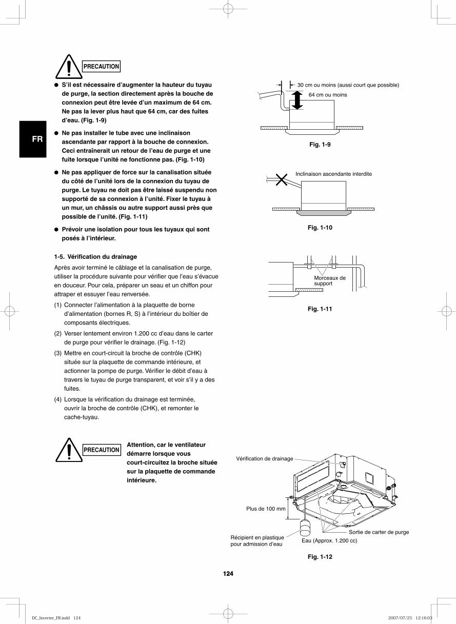
GB
FR
DE
IT
PT
GR
ES
124124
Fig. 1-9
30 cm ou moins (aussi court que possible)
64 cm ou moins
Fig. 1-10
Inclinaison ascendante interdite
Fig. 1-11
Fig. 1-12
Morceaux de support
Vérification de drainage
Sortie de carter de purge
Eau (Approx. 1.200 cc)Récipient en plastique pour admission dʼeau
Plus de 100 mm
● S’il est nécessaire d’augmenter la hauteur du tuyau de purge, la section directement après la bouche de connexion peut être levée d’un maximum de 64 cm. Ne pas la lever plus haut que 64 cm, car des fuites d’eau. (Fig. 1-9)
● Ne pas installer le tube avec une inclinaison ascendante par rapport à la bouche de connexion. Ceci entraînerait un retour de l’eau de purge et une fuite lorsque l’unité ne fonctionne pas. (Fig. 1-10)
● Ne pas appliquer de force sur la canalisation située du côté de l’unité lors de la connexion du tuyau de purge. Le tuyau ne doit pas être laissé suspendu non supporté de sa connexion à l’unité. Fixer le tuyau à un mur, un châssis ou autre support aussi près que possible de l’unité. (Fig. 1-11)
● Prévoir une isolation pour tous les tuyaux qui sont posés à l’intérieur.
1-5. Vérification du drainage
Après avoir terminé le câblage et la canalisation de purge, utiliser la procédure suivante pour vérifier que l’eau s’évacue en douceur. Pour cela, préparer un seau et un chiffon pour attraper et essuyer l’eau renversée.
(1) Connecter l’alimentation à la plaquette de borne d’alimentation (bornes R, S) à l’intérieur du boîtier de composants électriques.
(2) Verser lentement environ 1.200 cc d’eau dans le carter de purge pour vérifier le drainage. (Fig. 1-12)
(3) Mettre en court-circuit la broche de contrôle (CHK) située sur la plaquette de commande intérieure, et actionner la pompe de purge. Vérifier le débit d’eau à travers le tuyau de purge transparent, et voir s’il y a des fuites.
(4) Lorsque la vérification du drainage est terminée, ouvrir la broche de contrôle (CHK), et remonter le cache-tuyau.
Attention, car le ventilateur démarre lorsque vous court-circuitez la broche située sur la plaquette de commande intérieure.
PRECAUTION
PRECAUTION
DC_Inverter_FR.indd 124DC_Inverter_FR.indd 124 2007/07/25 12:16:032007/07/25 12:16:03
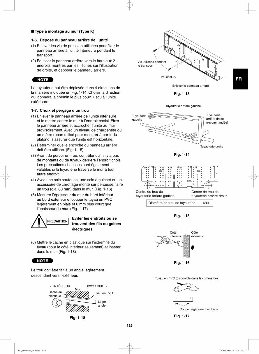
GB
FR
DE
IT
PT
GR
ES
125125
■ Type à montage au mur (Type K)
1-6. Dépose du panneau arrière de l’unité(1) Enlever les vis de pression utilisées pour fixer le
panneau arrière à l’unité intérieure pendant le transport.
(2) Pousser le panneau arrière vers le haut aux 2 endroits montrés par les flèches sur l’illustration de droite, et déposer le panneau arrière.
NOTE
La tuyauterie eut être déployée dans 4 directions de la manière indiquée en Fig. 1-14. Choisir la direction qui donnera le chemin le plus court jusqu’à l’unité extérieure.
1-7. Choix et perçage d’un trou(1) Enlever le panneau arrière de l’unité intérieure
et le mettre contre le mur à l’endroit choisi. Fixer le panneau arrière et accrocher l’unité au mur provisoirement. Avec un niveau de charpentier ou un mètre ruban utilisé pour mesurer à partir du plafond, s’assurer que l’unité est horizontale.
(2) Déterminer quelle encoche du panneau arrière doit être utilisée. (Fig. 1-15)
(3) Avant de percer un trou, contrôler qu’il n’y a pas de montants ou de tuyaux derrière l’endroit choisi. Les précautions ci-dessus sont également valables si la tuyauterie traverse le mur à tout autre endroit.
(4) Avec une scie sauteuse, une scie à guichet ou un accessoire de carottage monté sur perceuse, faire un trou (dia. 80 mm) dans le mur. (Fig. 1-16)
(5) Mesurer l’épaisseur du mur du bord intérieur au bord extérieur et couper le tuyau en PVC légèrement en biais et 6 mm plus court que l’épaisseur du mur. (Fig. 1-17)
(6) Mettre le cache en plastique sur l’extrémité du tuyau (pour le côté intérieur seulement) et insérer dans le mur. (Fig. 1-18)
NOTE
Le trou doit être fait à un angle légèrement descendant vers l’extérieur.
Fig. 1-13
Fig. 1-14
Fig. 1-15
Fig. 1-16
Fig. 1-17Fig. 1-18
PRECAUTIONEviter les endroits où se trouvent des fils ou gaines électriques.
INTÉRIEURMur
Tuyau en PVC
EXTÉRIEUR
Cache en plastique
Légerangle
Couper légèrement en biais
Tuyau en PVC (disponible dans le commerce)
Côtéintérieur
Côtéextérieur
Centre de trou de tuyauterie arrière gauche
Centre de trou de tuyauterie arrière droite
Diamètre de trou de tuyauterie ø80
Tuyauteriegauche
Tuyauteriearrière droite(recommandée)
Tuyauterie droite
Tuyauterie arrière gauche
Enlever le panneau arrière
Pousser
Vis utilisées pendant le transport
DC_Inverter_FR.indd 125DC_Inverter_FR.indd 125 2007/07/25 12:16:032007/07/25 12:16:03
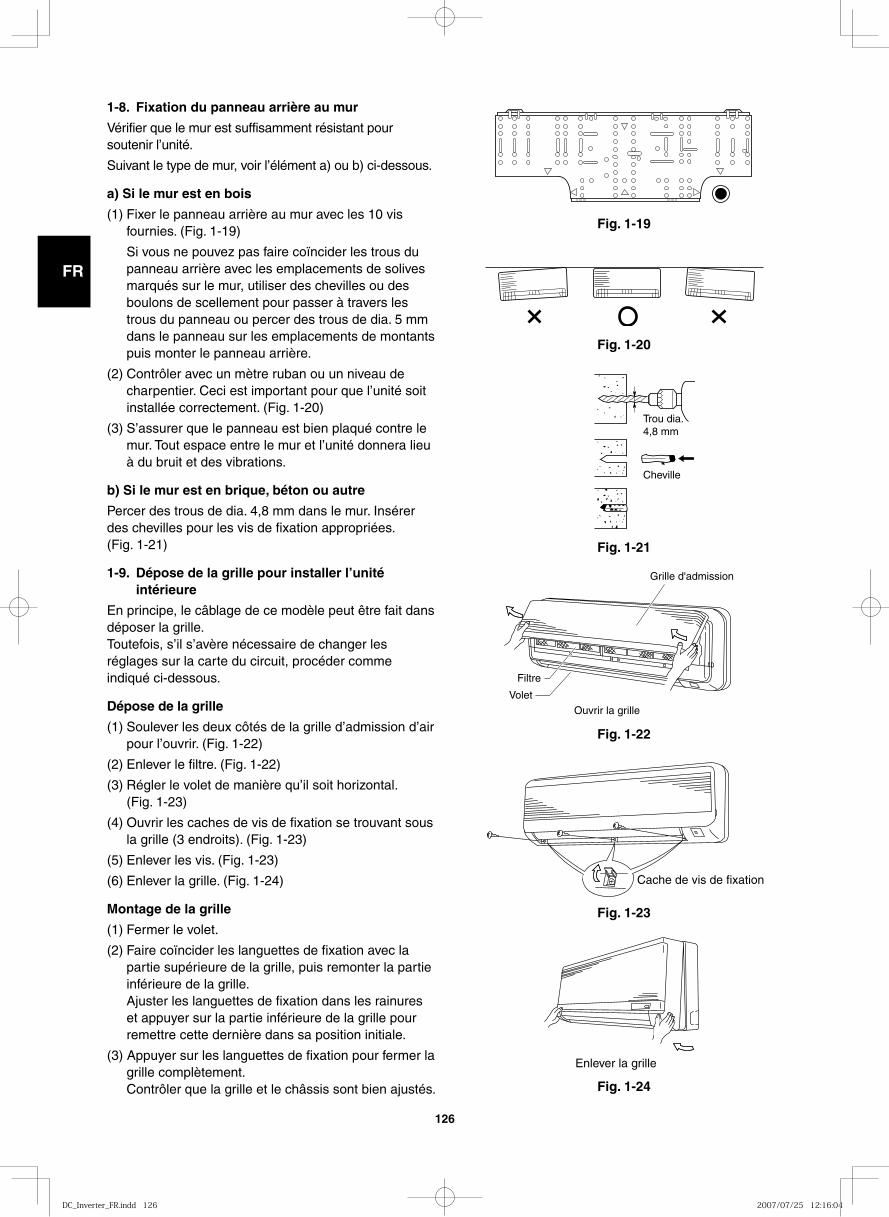
GB
FR
DE
IT
PT
GR
ES
126
Fig. 1-19
1-8. Fixation du panneau arrière au mur
Vérifier que le mur est suffisamment résistant pour soutenir l’unité.
Suivant le type de mur, voir l’élément a) ou b) ci-dessous.
a) Si le mur est en bois
(1) Fixer le panneau arrière au mur avec les 10 vis fournies. (Fig. 1-19)
Si vous ne pouvez pas faire coïncider les trous du panneau arrière avec les emplacements de solives marqués sur le mur, utiliser des chevilles ou des boulons de scellement pour passer à travers les trous du panneau ou percer des trous de dia. 5 mm dans le panneau sur les emplacements de montants puis monter le panneau arrière.
(2) Contrôler avec un mètre ruban ou un niveau de charpentier. Ceci est important pour que l’unité soit installée correctement. (Fig. 1-20)
(3) S’assurer que le panneau est bien plaqué contre le mur. Tout espace entre le mur et l’unité donnera lieu à du bruit et des vibrations.
b) Si le mur est en brique, béton ou autre
Percer des trous de dia. 4,8 mm dans le mur. Insérer des chevilles pour les vis de fixation appropriées.(Fig. 1-21)
1-9. Dépose de la grille pour installer l’unité intérieure
En principe, le câblage de ce modèle peut être fait dans déposer la grille.Toutefois, s’il s’avère nécessaire de changer les réglages sur la carte du circuit, procéder comme indiqué ci-dessous.
Dépose de la grille
(1) Soulever les deux côtés de la grille d’admission d’air pour l’ouvrir. (Fig. 1-22)
(2) Enlever le filtre. (Fig. 1-22)
(3) Régler le volet de manière qu’il soit horizontal.(Fig. 1-23)
(4) Ouvrir les caches de vis de fixation se trouvant sous la grille (3 endroits). (Fig. 1-23)
(5) Enlever les vis. (Fig. 1-23)
(6) Enlever la grille. (Fig. 1-24)
Montage de la grille
(1) Fermer le volet.
(2) Faire coïncider les languettes de fixation avec la partie supérieure de la grille, puis remonter la partie inférieure de la grille.
Ajuster les languettes de fixation dans les rainures et appuyer sur la partie inférieure de la grille pour remettre cette dernière dans sa position initiale.
(3) Appuyer sur les languettes de fixation pour fermer la grille complètement.
Contrôler que la grille et le châssis sont bien ajustés.
Fig. 1-20
Fig. 1-21
Fig. 1-22
Fig. 1-23
Fig. 1-24
Trou dia.4,8 mm
Cheville
Grille d'admission
Filtre
Volet
Ouvrir la grille
Cache de vis de fixation
Enlever la grille
DC_Inverter_FR.indd 126DC_Inverter_FR.indd 126 2007/07/25 12:16:042007/07/25 12:16:04
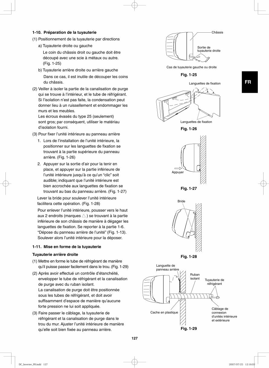
GB
FR
DE
IT
PT
GR
ES
127
1-10. Préparation de la tuyauterie
(1) Positionnement de la tuyauterie par directions
a) Tuyauterie droite ou gauche
Le coin du châssis droit ou gauche doit être découpé avec une scie à métaux ou autre. (Fig. 1-25)
b) Tuyauterie arrière droite ou arrière gauche
Dans ce cas, il est inutile de découper les coins du châssis.
(2) Veiller à isoler la partie de la canalisation de purge qui se trouve à l’intérieur, et le tube de réfrigérant.
Si l’isolation n’est pas faite, la condensation peut donner lieu à un ruissellement et endommager les murs et les meubles.
Les écrous évasés du type 25 (seulement) sont gros; par conséquent, utiliser le matériau d’isolation fourni.
(3) Pour fixer l’unité intérieure au panneau arrière
1. Lors de l’installation de l’unité intérieure, la positionner sur les languettes de fixation se trouvant à la partie supérieure du panneau arrière. (Fig. 1-26)
2. Appuyer sur la sortie d’air pour la tenir en place, et appuyer sur la partie inférieure de l’unité intérieure jusqu’à ce qu’un “clic” soit audible; indiquant que l’unité intérieure est bien accrochée aux languettes de fixation se trouvant au bas du panneau arrière. (Fig. 1-27)
Lever la bride pour soulever l’unité intérieure facilitera cette opération. (Fig. 1-28)
Pour enlever l’unité intérieure, pousser vers le haut aux 2 endroits (marques ▲▲ ) se trouvant à la partie inférieure de son châssis de manière à dégager les languettes de fixation. Se reporter à la partie 1-6. “Dépose du panneau arrière de l’unité” (Fig. 1-13).Soulever alors l’unité intérieure pour la déposer.
1-11. Mise en forme de la tuyauterie
Tuyauterie arrière droite
(1) Mettre en forme le tube de réfrigérant de manière qu’il puisse passer facilement dans le trou. (Fig. 1-29)
(2) Après avoir effectué un contrôle d’étanchéité, envelopper le tube de réfrigérant et la canalisation de purge avec du ruban isolant.
La canalisation de purge doit être positionnée sous les tubes de réfrigérant, et doit avoir suffisamment d’espace de manière qu’aucune forte pression ne lui soit appliquée.
(3) Faire passer le câblage, la tuyauterie de réfrigérant et la canalisation de purge dans le trou du mur. Ajuster l’unité intérieure de manière qu’elle soit bien fixée au panneau arrière.
Fig. 1-25
Châssis
Sortie detuyauterie droite
Cas de tuyauterie gauche ou droite
Fig. 1-26
Languettes de fixation
Languettes de fixation
Fig. 1-27
Appuyer
Fig. 1-28
Bride
Fig. 1-29
Rubanisolant Tuyauterie de
réfrigérant
Languette de panneau arrière
Cache en plastiqueCâblage de connexion d'unités intérieure et extérieure
DC_Inverter_FR.indd 127DC_Inverter_FR.indd 127 2007/07/25 12:16:052007/07/25 12:16:05
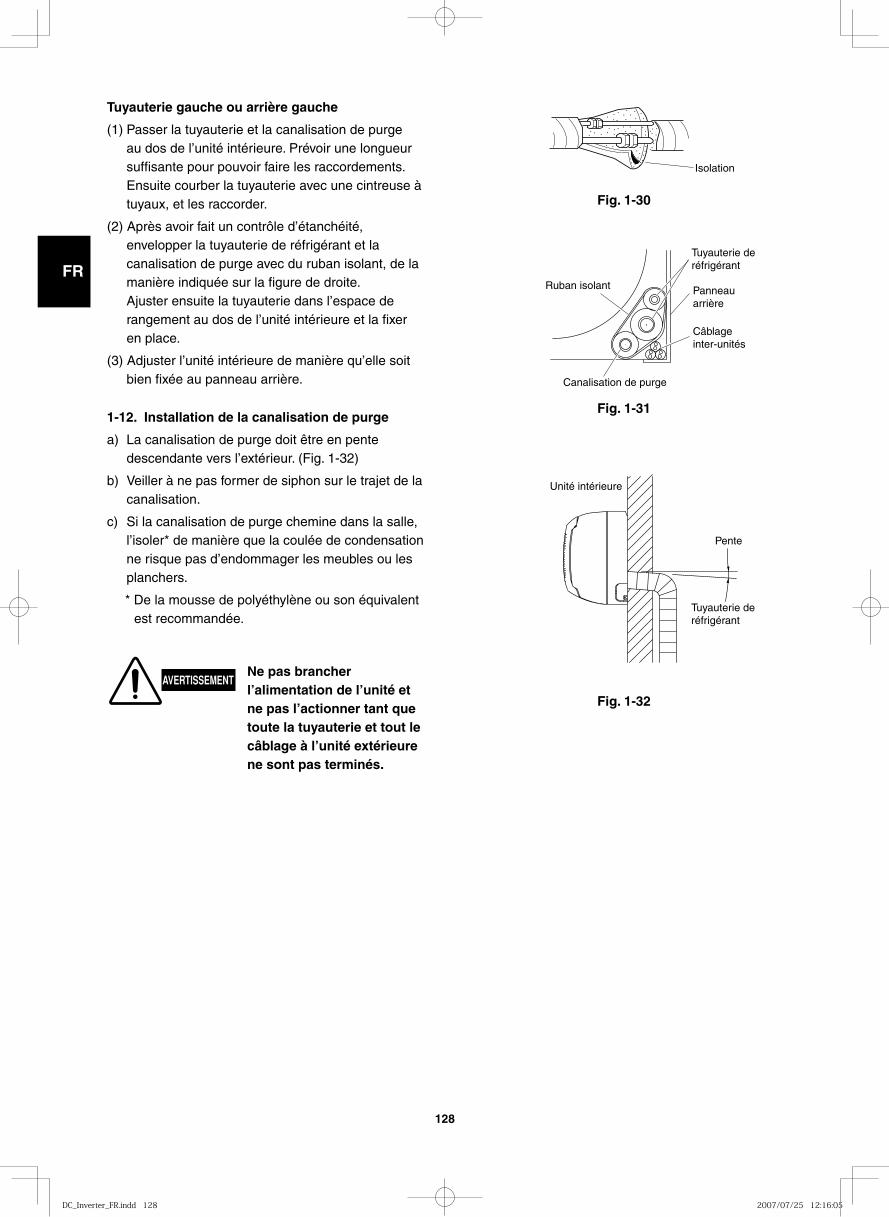
GB
FR
DE
IT
PT
GR
ES
128
Fig. 1-32
Fig. 1-30
Isolation
Fig. 1-31
Ruban isolant Panneauarrière
Câblageinter-unités
Tuyauterie de réfrigérant
Canalisation de purge
Unité intérieure
Pente
Tuyauterie deréfrigérant
1-12. Installation de la canalisation de purge
a) La canalisation de purge doit être en pente descendante vers l’extérieur. (Fig. 1-32)
b) Veiller à ne pas former de siphon sur le trajet de la canalisation.
c) Si la canalisation de purge chemine dans la salle, l’isoler* de manière que la coulée de condensation ne risque pas d’endommager les meubles ou les planchers.
* De la mousse de polyéthylène ou son équivalent est recommandée.
AVERTISSEMENTNe pas brancher l’alimentation de l’unité et ne pas l’actionner tant que toute la tuyauterie et tout le câblage à l’unité extérieure ne sont pas terminés.
Tuyauterie gauche ou arrière gauche
(1) Passer la tuyauterie et la canalisation de purge au dos de l’unité intérieure. Prévoir une longueur suffisante pour pouvoir faire les raccordements.
Ensuite courber la tuyauterie avec une cintreuse à tuyaux, et les raccorder.
(2) Après avoir fait un contrôle d’étanchéité, envelopper la tuyauterie de réfrigérant et la canalisation de purge avec du ruban isolant, de la manière indiquée sur la figure de droite.
Ajuster ensuite la tuyauterie dans l’espace de rangement au dos de l’unité intérieure et la fixer en place.
(3) Adjuster l’unité intérieure de manière qu’elle soit bien fixée au panneau arrière.
DC_Inverter_FR.indd 128DC_Inverter_FR.indd 128 2007/07/25 12:16:052007/07/25 12:16:05
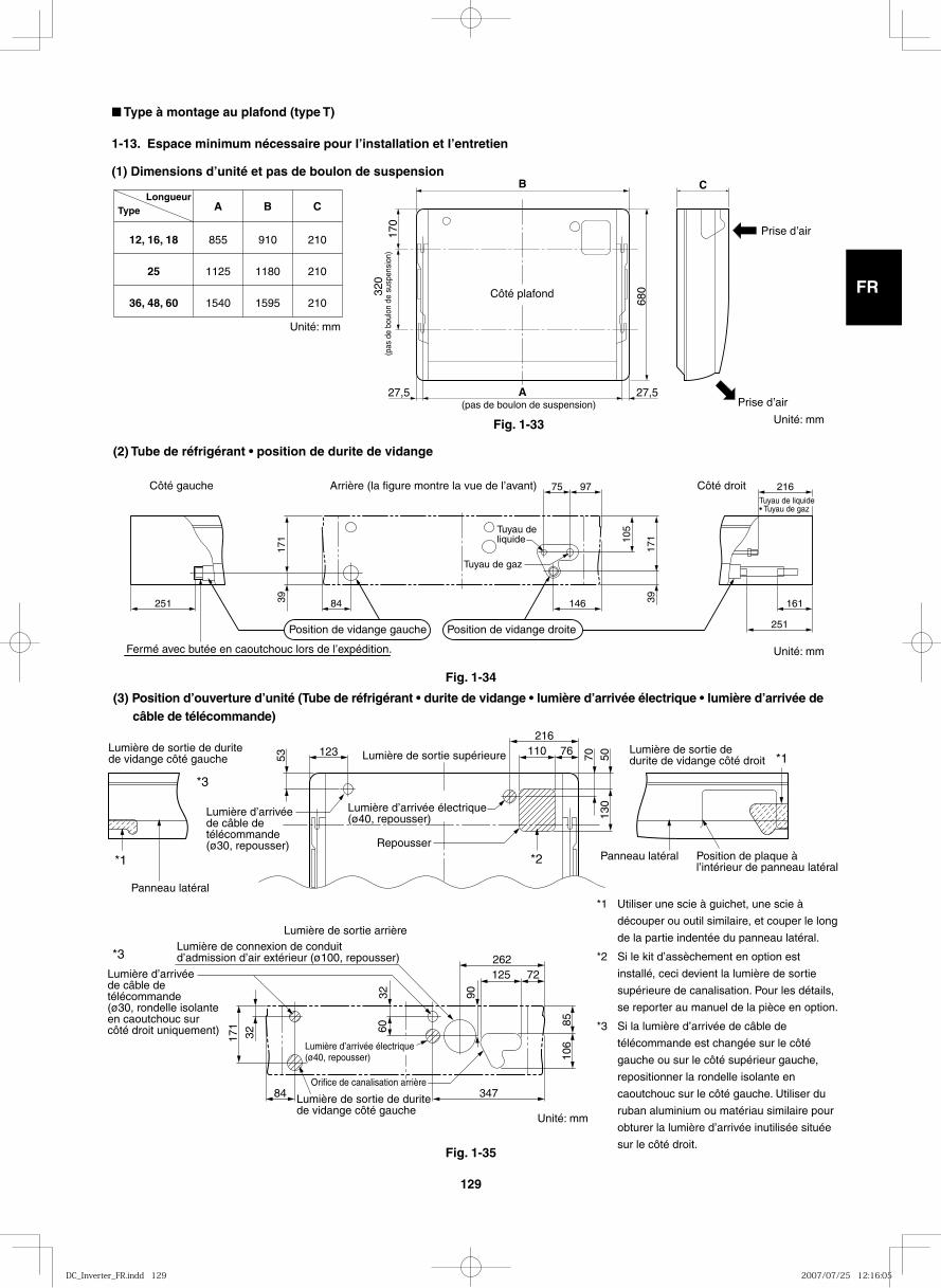
GB
FR
DE
IT
PT
GR
ES
129
12, 16, 18
25
36, 48, 60
855
1125
1540
910
1180
1595
210
210
210
A B CTypeLongueur
B
A
C
170
320
680
27,5 27,5
Côté plafond
(pas de boulon de suspension)
(pas
de
boul
on d
e su
spen
sion
)
Prise dʼair
Prise dʼair
(2) Tube de réfrigérant • position de durite de vidange
251 84 146 161
75 97 216
39 39
171 10
5
171
251
Côté droitCôté gauche Arrière (la figure montre la vue de l’avant)
Position de vidange gauche Position de vidange droite
Tuyau de gaz
Tuyau de liquide
Tuyau de liquide • Tuyau de gaz
Fermé avec butée en caoutchouc lors de l’expédition.
53 70123 110 76216
5013
0
Panneau latéral
Panneau latéral
Lumière de sortie de durite de vidange côté gauche
Lumière de sortie de durite de vidange côté gauche
Lumière de sortie supérieure
Repousser
84
32
3260
171
347
125 72
8510
6
90
262*3
*1
*1
*2
*3
Lumière d’arrivée de câble de télécommande (ø30, repousser)
Lumière d’arrivée de câble de télécommande (ø30, rondelle isolante en caoutchouc sur côté droit uniquement)
Lumière d’arrivée électrique (ø40, repousser)
Lumière de sortie de durite de vidange côté droit
Position de plaque à l’intérieur de panneau latéral
Lumière de sortie arrièreLumière de connexion de conduit d’admission d’air extérieur (ø100, repousser)
Orifice de canalisation arrière
Lumière d’arrivée électrique (ø40, repousser)
Fig. 1-33
Fig. 1-34
Unité: mm
Unité: mm
Unité: mm
■ Type à montage au plafond (type T)
1-13. Espace minimum nécessaire pour l’installation et l’entretien
(1) Dimensions d’unité et pas de boulon de suspension
(3) Position d’ouverture d’unité (Tube de réfrigérant • durite de vidange • lumière d’arrivée électrique • lumière d’arrivée de câble de télécommande)
Fig. 1-35
*1 Utiliser une scie à guichet, une scie à
découper ou outil similaire, et couper le long
de la partie indentée du panneau latéral.
*2 Si le kit d’assèchement en option est
installé, ceci devient la lumière de sortie
supérieure de canalisation. Pour les détails,
se reporter au manuel de la pièce en option.
*3 Si la lumière d’arrivée de câble de
télécommande est changée sur le côté
gauche ou sur le côté supérieur gauche,
repositionner la rondelle isolante en
caoutchouc sur le côté gauche. Utiliser du
ruban aluminium ou matériau similaire pour
obturer la lumière d’arrivée inutilisée située
sur le côté droit.
Unité: mm
DC_Inverter_FR.indd 129DC_Inverter_FR.indd 129 2007/07/25 12:16:052007/07/25 12:16:05
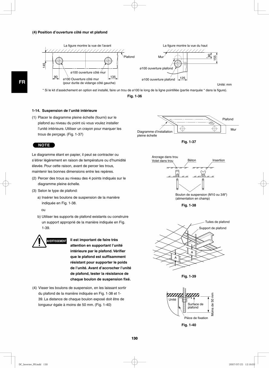
GB
FR
DE
IT
PT
GR
ES
130130
(4) Position d’ouverture côté mur et plafond
90
145
135 125
15590
ø100 ouverture côté mur
ø100 Ouverture côté mur(pour durite de vidange côté gauche)
ø100 ouverture plafond
ø100 ouverture plafond
Plafond Mur
La figure montre la vue de lʼavant La figure montre la vue du haut
*
Plafond
MurDiagramme dʼinstallation pleine échelle
Fig. 1-37
Fig. 1-36
Fig. 1-38
1-14. Suspension de l’unité intérieure
(1) Placer le diagramme pleine échelle (fourni) sur le
plafond au niveau du point où vous voulez installer
l’unité intérieure. Utiliser un crayon pour marquer les
trous de perçage. (Fig. 1-37)
NOTE
Le diagramme étant en papier, il peut se contracter ou
s’étirer légèrement en raison de température ou d’humidité
élevée. Pour cette raison, avant de percer les trous,
maintenir les bonnes dimensions entre les repères.
(2) Percer des trous au niveau des 4 points indiqués sur le
diagramme pleine échelle.
(3) Selon le type de plafond:
a) Insérer les boulons de suspension de la manière
indiquée en Fig. 1-38.
ou
b) Utiliser les supports de plafond existants ou construire
un support approprié de la manière indiquée en Fig.
1-39.
(4) Visser les boulons de suspension, en les laissant sortir
du plafond de la manière indiquée en Fig. 1-38 et 1-
39. La distance de chaque boulon exposé doit être de
longueur égale à moins de 50 mm. (Fig. 1-40)
Ancrage dans trouVolet dans trou Béton Insertion
Boulon de suspension (M10 ou 3/8")(alimentation en champ)
Fig. 1-39
Fig. 1-40
A
A
Support de plafond
Tuiles de plafond
Surface de plafond
Moi
ns d
e 50
mm
Pièce de fixation
Unité
Unité: mm
AVERTISSEMENT Il est important de faire très
attention en supportant l’unité
intérieure par le plafond. Vérifier
que le plafond est suffisamment
résistant pour supporter le poids
de l’unité. Avant d’accrocher l’unité
de plafond, tester la résistance de
chaque boulon de suspension fixé.
* Si le kit d’assèchement en option est installé, faire un trou de ø100 le long de la ligne pointillée (partie marquée * dans la figure).
DC_Inverter_FR.indd 130DC_Inverter_FR.indd 130 2007/07/25 12:16:052007/07/25 12:16:05
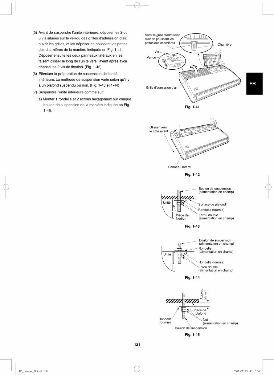
GB
FR
DE
IT
PT
GR
ES
131131
Fig. 1-41G
lisser
Verrou
Vis
Sortir la grille dʼadmission dʼair en poussant les pattes des charnières Charnière
Grille dʼadmission dʼair
Fig. 1-42
Glisser vers le côté avant
Panneau latéral
Fig. 1-43
Boulon de suspension(alimentation en champ)
Surface de plafond
Rondelle (fournie)
Ecrou double (alimentation en champ)
Pièce de fixation
Unité
Fig. 1-44
Rondelle (fournie)
Rondelle (alimentation en champ)
Boulon de suspension(alimentation en champ)
Ecrou double (alimentation en champ)
Unité
Fig. 1-45
Boulon de suspension
Rondelle (fournie)
Nut(alimentation en champ)
Surface deplafond
App
rox.
25
mm
(5) Avant de suspendre l’unité intérieure, déposer les 2 ou
3 vis situées sur le verrou des grilles d’admission d’air,
ouvrir les grilles, et les déposer en poussant les pattes
des charnières de la manière indiquée en Fig. 1-41.
Déposer ensuite les deux panneaux latéraux en les
faisant glisser le long de l’unité vers l’avant après avoir
déposé les 2 vis de fixation. (Fig. 1-42)
(6) Effectuer la préparation de suspension de l’unité
intérieure. La méthode de suspension varie selon qu’il y
a un plafond suspendu ou non. (Fig. 1-43 et 1-44)
(7) Suspendre l’unité intérieure comme suit:
a) Monter 1 rondelle et 2 écrous hexagonaux sur chaque
boulon de suspension de la manière indiquée en Fig.
1-45.
DC_Inverter_FR.indd 131DC_Inverter_FR.indd 131 2007/07/25 12:16:062007/07/25 12:16:06
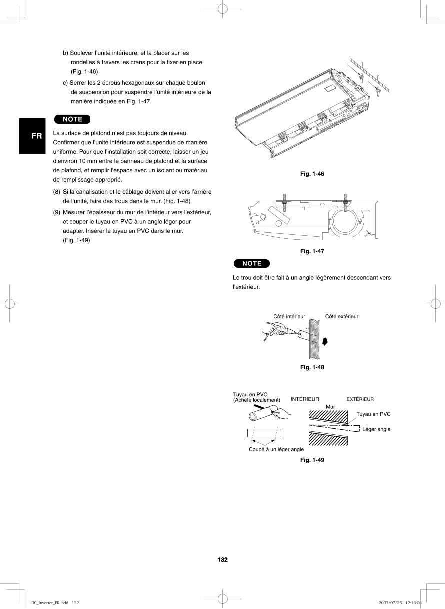
GB
FR
DE
IT
PT
GR
ES
132132
Fig. 1-46
Fig. 1-47
Fig. 1-48
Côté intérieur Côté extérieur
Fig. 1-49
INTÉRIEUR EXTÉRIEUR
Mur
Léger angle
Tuyau en PVC
Coupé à un léger angle
Tuyau en PVC (Acheté localement)
b) Soulever l’unité intérieure, et la placer sur les
rondelles à travers les crans pour la fixer en place.
(Fig. 1-46)
c) Serrer les 2 écrous hexagonaux sur chaque boulon
de suspension pour suspendre l’unité intérieure de la
manière indiquée en Fig. 1-47.
NOTE
La surface de plafond n’est pas toujours de niveau.
Confirmer que l’unité intérieure est suspendue de manière
uniforme. Pour que l’installation soit correcte, laisser un jeu
d’environ 10 mm entre le panneau de plafond et la surface
de plafond, et remplir l’espace avec un isolant ou matériau
de remplissage approprié.
(8) Si la canalisation et le câblage doivent aller vers l’arrière
de l’unité, faire des trous dans le mur. (Fig. 1-48)
(9) Mesurer l’épaisseur du mur de l’intérieur vers l’extérieur,
et couper le tuyau en PVC à un angle léger pour
adapter. Insérer le tuyau en PVC dans le mur.
(Fig. 1-49)
NOTE
Le trou doit être fait à un angle légèrement descendant vers
l’extérieur.
DC_Inverter_FR.indd 132DC_Inverter_FR.indd 132 2007/07/25 12:16:062007/07/25 12:16:06
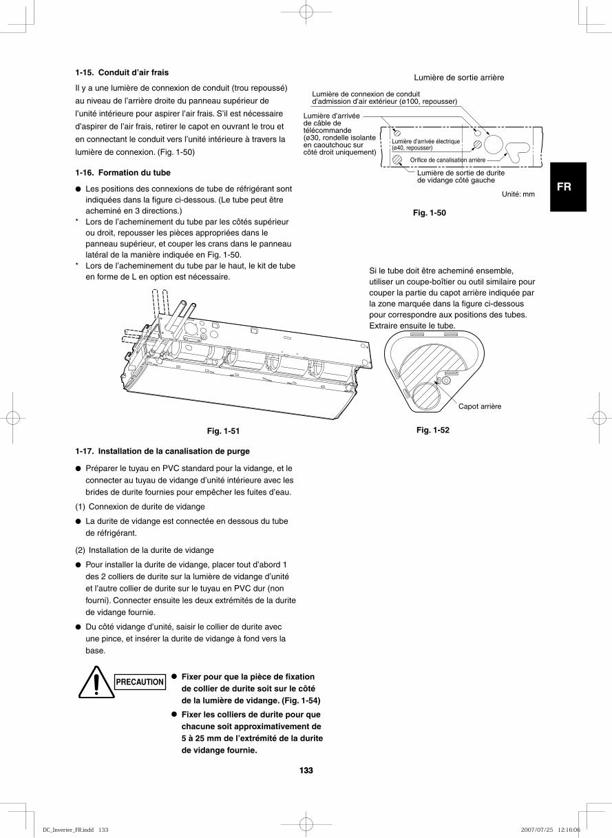
GB
FR
DE
IT
PT
GR
ES
133133
Lumière de sortie de durite de vidange côté gauche
Lumière d’arrivée de câble de télécommande (ø30, rondelle isolante en caoutchouc sur côté droit uniquement)
Lumière d’arrivée électrique (ø40, repousser)
Lumière de sortie arrière
Lumière de connexion de conduit d’admission d’air extérieur (ø100, repousser)
Orifice de canalisation arrière
1-15. Conduit d’air frais
Il y a une lumière de connexion de conduit (trou repoussé)
au niveau de l’arrière droite du panneau supérieur de
l’unité intérieure pour aspirer l’air frais. S’il est nécessaire
d’aspirer de l’air frais, retirer le capot en ouvrant le trou et
en connectant le conduit vers l’unité intérieure à travers la
lumière de connexion. (Fig. 1-50)
1-16. Formation du tube
● Les positions des connexions de tube de réfrigérant sont indiquées dans la figure ci-dessous. (Le tube peut être acheminé en 3 directions.)
* Lors de l’acheminement du tube par les côtés supérieur ou droit, repousser les pièces appropriées dans le panneau supérieur, et couper les crans dans le panneau latéral de la manière indiquée en Fig. 1-50.
* Lors de l’acheminement du tube par le haut, le kit de tube en forme de L en option est nécessaire.
1-17. Installation de la canalisation de purge
● Préparer le tuyau en PVC standard pour la vidange, et le connecter au tuyau de vidange d’unité intérieure avec les brides de durite fournies pour empêcher les fuites d’eau.
(1) Connexion de durite de vidange
● La durite de vidange est connectée en dessous du tube de réfrigérant.
(2) Installation de la durite de vidange
● Pour installer la durite de vidange, placer tout d’abord 1 des 2 colliers de durite sur la lumière de vidange d’unité et l’autre collier de durite sur le tuyau en PVC dur (non fourni). Connecter ensuite les deux extrémités de la durite de vidange fournie.
● Du côté vidange d’unité, saisir le collier de durite avec une pince, et insérer la durite de vidange à fond vers la
base.
Fig. 1-50
Capot arrière
● Fixer pour que la pièce de fixation de collier de durite soit sur le côté de la lumière de vidange. (Fig. 1-54)
● Fixer les colliers de durite pour que chacune soit approximativement de 5 à 25 mm de l’extrémité de la durite de vidange fournie.
Si le tube doit être acheminé ensemble, utiliser un coupe-boîtier ou outil similaire pour couper la partie du capot arrière indiquée par la zone marquée dans la figure ci-dessous pour correspondre aux positions des tubes. Extraire ensuite le tube.
Fig. 1-51 Fig. 1-52
PRECAUTION
Unité: mm
DC_Inverter_FR.indd 133DC_Inverter_FR.indd 133 2007/07/25 12:16:062007/07/25 12:16:06
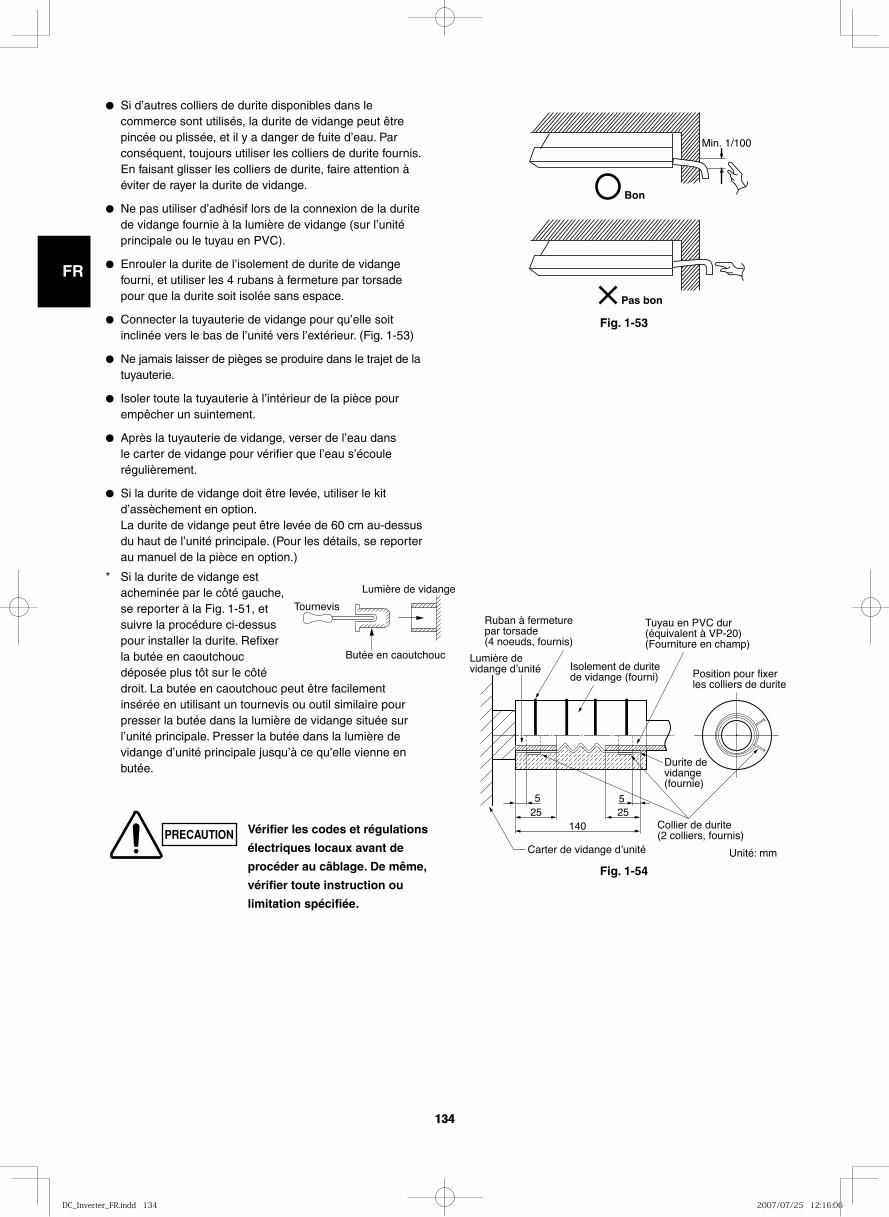
GB
FR
DE
IT
PT
GR
ES
134134
14025 25
55
Lumière de vidange dʼunité
Ruban à fermeture par torsade (4 noeuds, fournis)
Isolement de durite de vidange (fourni)
Tuyau en PVC dur (équivalent à VP-20) (Fourniture en champ)
Position pour fixer les colliers de durite
Durite de vidange (fournie)
Collier de durite (2 colliers, fournis)
Carter de vidange dʼunité
Bon
Min. 1/100
Pas bon
Fig. 1-53
● Si d’autres colliers de durite disponibles dans le commerce sont utilisés, la durite de vidange peut être pincée ou plissée, et il y a danger de fuite d’eau. Par conséquent, toujours utiliser les colliers de durite fournis. En faisant glisser les colliers de durite, faire attention à éviter de rayer la durite de vidange.
● Ne pas utiliser d’adhésif lors de la connexion de la durite de vidange fournie à la lumière de vidange (sur l’unité principale ou le tuyau en PVC).
● Enrouler la durite de l’isolement de durite de vidange fourni, et utiliser les 4 rubans à fermeture par torsade pour que la durite soit isolée sans espace.
● Connecter la tuyauterie de vidange pour qu’elle soit inclinée vers le bas de l’unité vers l’extérieur. (Fig. 1-53)
● Ne jamais laisser de pièges se produire dans le trajet de la tuyauterie.
● Isoler toute la tuyauterie à l’intérieur de la pièce pour empêcher un suintement.
● Après la tuyauterie de vidange, verser de l’eau dans le carter de vidange pour vérifier que l’eau s’écoule régulièrement.
● Si la durite de vidange doit être levée, utiliser le kit d’assèchement en option. La durite de vidange peut être levée de 60 cm au-dessus du haut de l’unité principale. (Pour les détails, se reporter au manuel de la pièce en option.)
* Si la durite de vidange est acheminée par le côté gauche, se reporter à la Fig. 1-51, et suivre la procédure ci-dessus pour installer la durite. Refixer la butée en caoutchouc déposée plus tôt sur le côté droit. La butée en caoutchouc peut être facilement insérée en utilisant un tournevis ou outil similaire pour presser la butée dans la lumière de vidange située sur l’unité principale. Presser la butée dans la lumière de vidange d’unité principale jusqu’à ce qu’elle vienne en butée.
Tournevis
Lumière de vidange
Butée en caoutchouc
Vérifier les codes et régulations
électriques locaux avant de
procéder au câblage. De même,
vérifier toute instruction ou
limitation spécifiée.
Unité: mm
PRECAUTION
Fig. 1-54
DC_Inverter_FR.indd 134DC_Inverter_FR.indd 134 2007/07/25 12:16:062007/07/25 12:16:06
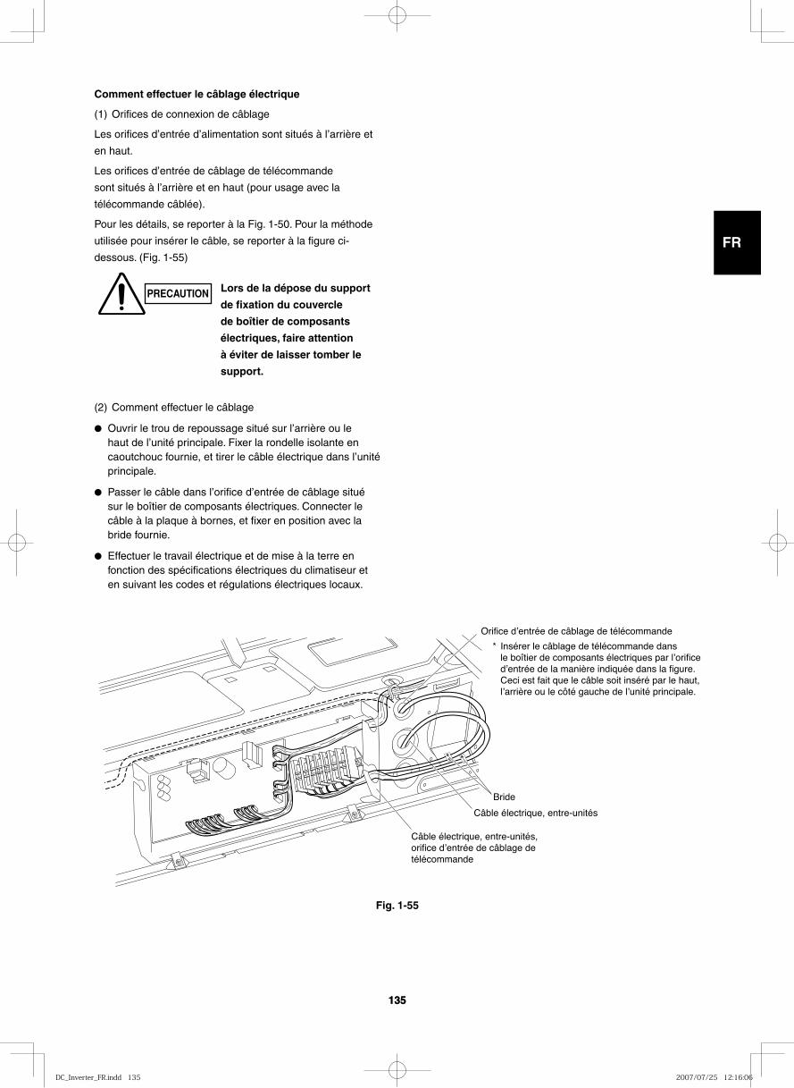
GB
FR
DE
IT
PT
GR
ES
135135
Orifice dʼentrée de câblage de télécommande
Insérer le câblage de télécommande dans le boîtier de composants électriques par lʼorifice dʼentrée de la manière indiquée dans la figure. Ceci est fait que le câble soit inséré par le haut, lʼarrière ou le côté gauche de lʼunité principale.
Bride
Câble électrique, entre-unités
Câble électrique, entre-unités, orifice dʼentrée de câblage de télécommande
*
Comment effectuer le câblage électrique
(1) Orifices de connexion de câblage
Les orifices d’entrée d’alimentation sont situés à l’arrière et
en haut.
Les orifices d’entrée de câblage de télécommande
sont situés à l’arrière et en haut (pour usage avec la
télécommande câblée).
Pour les détails, se reporter à la Fig. 1-50. Pour la méthode
utilisée pour insérer le câble, se reporter à la figure ci-
dessous. (Fig. 1-55)
(2) Comment effectuer le câblage
● Ouvrir le trou de repoussage situé sur l’arrière ou le haut de l’unité principale. Fixer la rondelle isolante en caoutchouc fournie, et tirer le câble électrique dans l’unité principale.
● Passer le câble dans l’orifice d’entrée de câblage situé sur le boîtier de composants électriques. Connecter le câble à la plaque à bornes, et fixer en position avec la bride fournie.
● Effectuer le travail électrique et de mise à la terre en fonction des spécifications électriques du climatiseur et en suivant les codes et régulations électriques locaux.
Fig. 1-55
PRECAUTION Lors de la dépose du support
de fixation du couvercle
de boîtier de composants
électriques, faire attention
à éviter de laisser tomber le
support.
DC_Inverter_FR.indd 135DC_Inverter_FR.indd 135 2007/07/25 12:16:062007/07/25 12:16:06
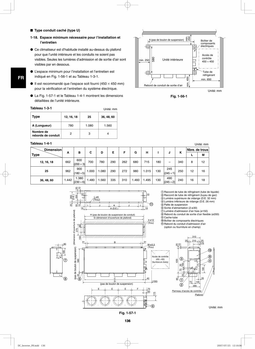
GB
FR
DE
IT
PT
GR
ES
136136
Fig. 1-56-1
Fig. 1-57-1
Unité intérieure
Accès de contrôle 450 × 450min. 250
min
. 400 min. 650
580
A (pas de boulon de suspension) Boîtier de composants électriques
Tube de réfrigérant
min
. 25
0
Rebord de conduit de sortie dʼair
■ Type conduit caché (type U)
1-18. Espace minimum nécessaire pour l’installation et l’entretien
● Ce climatiseur est d’habitude installé au-dessus du plafond pour que l’unité intérieure et les conduits ne soient pas visibles. Seules les lumières d’admission et de sortie d’air sont visibles par en dessous.
● L’espace minimum pour l’installation et l’entretien est indiqué en Fig. 1-56-1 et au Tableau 1-3-1.
● Il est recommandé que l’espace soit fourni (450 × 450 mm) pour la vérification et l’entretien du système électrique.
● La Fig. 1-57-1 et le Tableau 1-4-1 montrent les dimensions détaillées de l’unité intérieure.
Tableau 1-3-1
Tableau 1-4-1
Type
A (Longueur)
Nombre de rebords de conduit
36, 48, 60
1.560
4
25
1.080
3
12, 16, 18
780
2
DimensionType
12, 16, 18
25
36, 48, 60
E F G I J K
662600
700 780 290 262 680 715 180 – 340 8 12(200 × 3)
962900
1.000 1.080 290 272 980 1.015 130245
250 12 16(180 × 5) (245 × 1)
1.4421.380
1.480 1.560 335 310 1.460 1.495 130490
240 16 18(230 × 6) (245 × 2)
Nbre. de trousL M
C DBA H
9
10
9
10
11
11
M-ø3,3
4-ø12
(Trou)
A (D.E.)
L-ø6
I
10 10
105555
200
10 IJJ K
B
CD (150)
40
E E E F 7565
285
70 130
25 210
310
25175
35
903131
25
100
185
580
25
115
190
85
2570
30 160
630
25 10
8827
5(d
imen
sion
d’o
uver
ture
de
plaf
ond)
260
(D.E
.)
1919
H (pas de boulon de suspension de conduit)G (dimension d’ouverture de plafond)
(Trou)
(Trou)
Raccord de tube de réfrigérant (tube de liquide) Raccord de tube de réfrigérant (tuyau de gaz) Lumière supérieure de vidange (D.E. 32 mm)Lumière inférieure de vidange (D.E. 26 mm)Patte de suspensionSortie d’alimentation (2-ø30)Lumière d’admission d’air frais (ø150)Rebord du conduit de sortie d’air flexible (ø200)Cache-tubeBoîtier de composants électriquesRebord du conduit d’admission d’air (option ou fourniture en champ)
Accès de contrôle(450 × 450)
(fourniture en champ)
Panneau d’accès de contrôle
Plafond
(pas de boulon de suspension)
(pas
de
boul
on d
e su
spen
sion
)
Unité: mm
Unité: mm
Unité: mm
Unité: mm
DC_Inverter_FR.indd 136DC_Inverter_FR.indd 136 2007/07/25 12:16:062007/07/25 12:16:06

GB
FR
DE
IT
PT
GR
ES
137
Fig. 1-56-2
min.250 580
min
.400
A (Pas de boulon de suspension) min
.25
0
Unité intérieure
min.650
Boîtier d’élémentsélectriques
Trappe devisite450 450
Tuyauterie deréfrigérant
Cette page est seulement pour la version espagnole.
● Cet appareil de climatisation est généralement installé au-dessus du plafond de manière que l’unité intérieure et les conduits ne soient pas visibles. Seules les lumières d’admission et de sortie d’air sont visibles par en-dessous.
● L’espace minimun pour l’installation et la révision est indiqué en Fig. 1-56-2 et dans le Tableau 1-3-2.
● Il est recommandé de prévoir un espace (450 × 450 mm) pour le contrôle et la révision du système électrique.
● La Fig. 1-57-2 et le Tableau 1-4-2 indiquent les dimensions détaillées de l’unité intérieure.
Type
A (Longueur)
36, 48, 60
1.560
25
1.080
18
780
DimensionType
18
25
36, 48, 60
E F G H I J K
646 500
700 780 18 12 73 96 492 (100 × 5)
946 900
1.000 1.080 26 20 23 41 782 (100 × 9)
1.4261.300
1.480 1.560 26 28 63 81 1.262
161
171
182 (100 × 13)
300 (100 × 3)
700 (100 × 7)
1.100(100 × 11)
C D B A Nombre de trous
262
100
580
25
H H I (Pas
de
boul
on d
e su
spen
sion
)
A (D.E. de collerette)
Côté lumière d’admission
(D.E. de collerette)Côté conduit de sortie
J (D.E. de collerette)
27
B G G
K 40
C
(Pas de boulon de suspension)
75
(150)
115 18
6
65
90
100
43 43
185
186
310
262
31 100p×2=200 31
35
70 130
175
630
31
25
190
285
160
25
30
E- 3.1(Trou)
F- 3.3(Trou)
Panneau de trappe de visite
Plafond
1
2
3
4
9
10
11
6
5
7
8
12
13
Trappe de visite(450 450)
(Fournituresur chantier)
Unité: mm
Unité: mm
Unité: mm
Unité: mm
Raccord de tuyauterie de réfrigérant (tube de liquide)Raccord de tuyauterie de réfrigérant (tube de gaz)Lumière de purge supérieure VP25 (D.E. 32 mm)Tuyau flexible 200 fourniLumière de purge inférieure VP25 (D.E. 32 mm)Patte de suspension (4 – 12 × 37 mm)Sortie d’alimentation (2 – ø30 mm)Lumière d’admission d’air frais (ø150 mm)Collerette pour conduit flexible de sortie d’airCouvercle de tube
Collerette pour conduit d’admission d’airBoîtier d’éléments électriques
11 Résistance de poussée du vent10
12
Filtre13
Fig. 1-57-2
Tableau 1-4-2
Tableau 1-3-2
DC_Inverter_FR.indd 137DC_Inverter_FR.indd 137 2007/07/25 12:16:062007/07/25 12:16:06
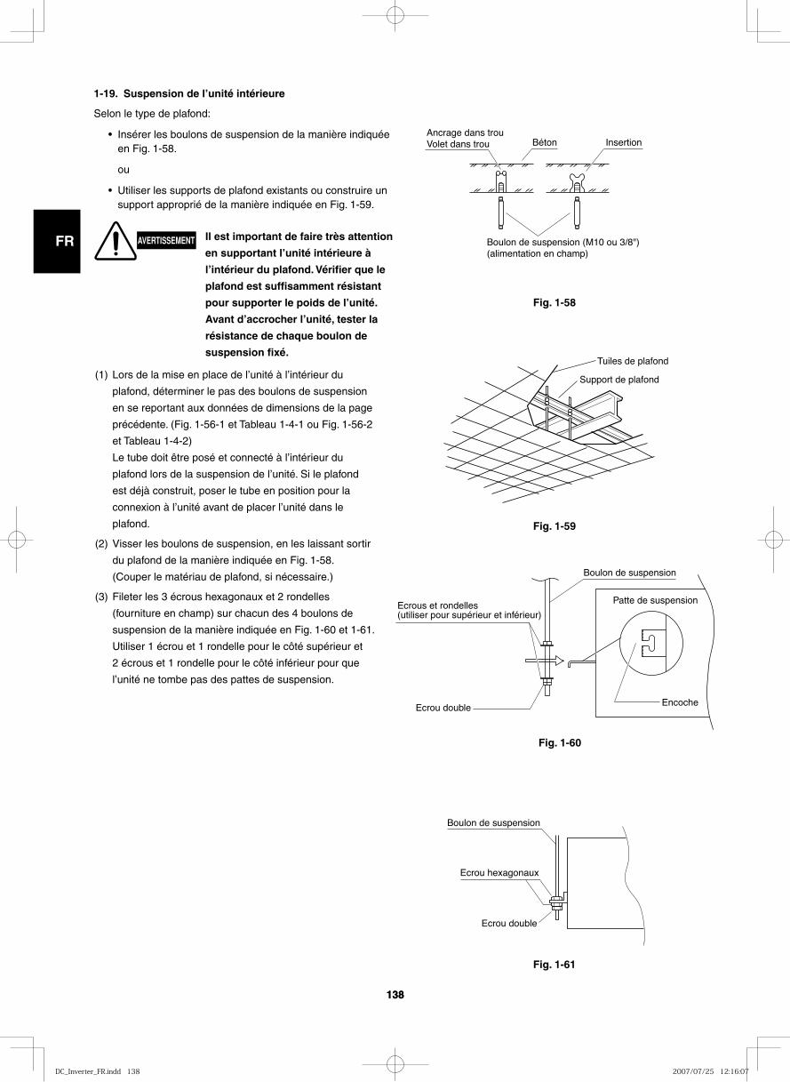
GB
FR
DE
IT
PT
GR
ES
138138
Fig. 1-58
1-19. Suspension de l’unité intérieure
Selon le type de plafond:
• Insérer les boulons de suspension de la manière indiquée en Fig. 1-58.
ou
• Utiliser les supports de plafond existants ou construire un support approprié de la manière indiquée en Fig. 1-59.
Ancrage dans trouVolet dans trou Béton Insertion
Boulon de suspension (M10 ou 3/8")(alimentation en champ)
Fig. 1-59
Fig. 1-60
Fig. 1-61
Support de plafond
Tuiles de plafond
Ecrous et rondelles (utiliser pour supérieur et inférieur)
Boulon de suspension
Patte de suspension
EncocheEcrou double
Boulon de suspension
Ecrou double
Ecrou hexagonaux
(1) Lors de la mise en place de l’unité à l’intérieur du
plafond, déterminer le pas des boulons de suspension
en se reportant aux données de dimensions de la page
précédente. (Fig. 1-56-1 et Tableau 1-4-1 ou Fig. 1-56-2
et Tableau 1-4-2)
Le tube doit être posé et connecté à l’intérieur du
plafond lors de la suspension de l’unité. Si le plafond
est déjà construit, poser le tube en position pour la
connexion à l’unité avant de placer l’unité dans le
plafond.
(2) Visser les boulons de suspension, en les laissant sortir
du plafond de la manière indiquée en Fig. 1-58.
(Couper le matériau de plafond, si nécessaire.)
(3) Fileter les 3 écrous hexagonaux et 2 rondelles
(fourniture en champ) sur chacun des 4 boulons de
suspension de la manière indiquée en Fig. 1-60 et 1-61.
Utiliser 1 écrou et 1 rondelle pour le côté supérieur et
2 écrous et 1 rondelle pour le côté inférieur pour que
l’unité ne tombe pas des pattes de suspension.
AVERTISSEMENT Il est important de faire très attention
en supportant l’unité intérieure à
l’intérieur du plafond. Vérifier que le
plafond est suffisamment résistant
pour supporter le poids de l’unité.
Avant d’accrocher l’unité, tester la
résistance de chaque boulon de
suspension fixé.
DC_Inverter_FR.indd 138DC_Inverter_FR.indd 138 2007/07/25 12:16:072007/07/25 12:16:07
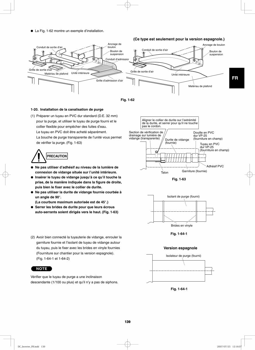
GB
FR
DE
IT
PT
GR
ES
139139
● La Fig. 1-62 montre un exemple d’installation.
Conduit de sortie d’air
Grille de sortie d’air
Matériau de plafond Unité intérieure
Ancrage deboulon
Boulon desuspension
Conduit d’admission
Grille d’admission d’air
Conduit de sortie d’air
Grille de sortie d’air
Matériau de plafond
Unité intérieure
Ancrage de boulon
Boulon desuspension
(Ce type est seulement pour la version espagnole.)
Fig. 1-62
Fig. 1-63
Fig. 1-64-1
Douille en PVC dur VP-25 (fourniture en champ)
Tuyau en PVC dur VP-25 (fourniture en champ)
Adhésif PVC
Garniture (fournie)Talon
Section de vérification de drainage sur lumière de vidange (transparente)
Aligner le collier de durite sur l’extrémité de la durite, et serrer pour qu’il ne touche pas le cordon.
Durite de vidange (fournie)
Brides en vinyle
Isolant de purge (fourni)
1-20. Installation de la canalisation de purge
(1) Préparer un tuyau en PVC dur standard (D.E. 32 mm)
pour la purge, et utiliser le tuyau de purge fourni et le
collier flexible pour empêcher des fuites d’eau.
Le tuyau en PVC doit être acheté séparément.
La bouche de purge transparente de l’unité vous permet
de vérifier la purge. (Fig. 1-63)
● Ne pas utiliser d’adhésif au niveau de la lumière de connexion de vidange située sur l’unité intérieure.
● Insérer le tuyau de vidange jusqu’à ce qu’il touche la prise, de la manière indiquée dans la figure de droite, puis bien le fixer avec le collier de durite.
● Ne pas utiliser la durite de vidange fournie courbée à un angle de 90°. (La courbure maximum autorisée est de 45°.)
● Serrer les brides de durite pour que leurs écrous auto-serrants soient dirigés vers le haut. (Fig. 1-63)
(2) Avoir bien connecté la tuyauterie de vidange, enrouler la
garniture fournie et l’isolant de tuyau de vidange autour
du tuyau, puis le fixer avec les brides en vinyle fournies
(Fourniture sur chantier pour la version espagnole).
(Fig. 1-64-1 et 1-64-2)
NOTE
Vérifier que le tuyau de purge a une inclinaison
descendante (1/100 ou plus) et qu’il n’y a pas de siphons.
PRECAUTION
Fig. 1-64-1
Isolateur de purge (fourni)
Version espagnole
DC_Inverter_FR.indd 139DC_Inverter_FR.indd 139 2007/07/25 12:16:072007/07/25 12:16:07
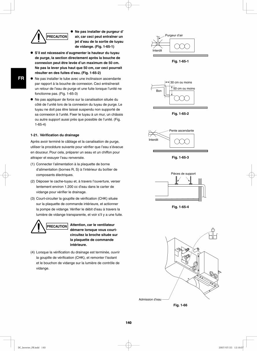
GB
FR
DE
IT
PT
GR
ES
140140
Fig. 1-65-1
Fig. 1-65-2
Fig. 1-65-3
Fig. 1-65-4
Fig. 1-66
Purgeur dʼair
Interdit
30 cm ou moins
50 cm ou moinsBon
Interdit
Pente ascendante
Pièces de support
Admission dʼeau
● S’il est nécessaire d’augmenter la hauteur du tuyau de purge, la section directement après la bouche de connexion peut être levée d’un maximum de 50 cm. Ne pas la lever plus haut que 50 cm, car ceci pourrait résulter en des fuites d’eau. (Fig. 1-65-2)
● Ne pas installer le tube avec une inclinaison ascendante par rapport à la bouche de connexion. Ceci entraînerait un retour de l’eau de purge et une fuite lorsque l’unité ne
fonctionne pas. (Fig. 1-65-3)
● Ne pas appliquer de force sur la canalisation située du côté de l’unité lors de la connexion du tuyau de purge. Le tuyau ne doit pas être laissé suspendu non supporté de
sa connexion à l’unité. Fixer le tuyau à un mur, un châssis ou autre support aussi près que possible de l’unité. (Fig. 1-65-4)
1-21. Vérification du drainage
Après avoir terminé le câblage et la canalisation de purge,
utiliser la procédure suivante pour vérifier que l’eau s’évacue
en douceur. Pour cela, préparer un seau et un chiffon pour
attraper et essuyer l’eau renversée.
(1) Connecter l’alimentation à la plaquette de borne
d’alimentation (bornes R, S) à l’intérieur du boîtier de
composants électriques.
(2) Déposer le cache-tuyau et, à travers l’ouverture, verser
lentement environ 1.200 cc d’eau dans le carter de
vidange pour vérifier le drainage.
(3) Court-circuiter la goupille de vérification (CHK) située
sur la plaquette de commande intérieure, et actionner
la pompe de vidange. Vérifier le débit d’eau à travers la
lumière de vidange transparente, et voir s’il y a une fuite.
(4) Lorsque la vérification du drainage est terminée, ouvrir
la goupille de vérification (CHK), et remonter l’isolant
et le bouchon de vidange sur la lumière de contrôle de
vidange.
● Ne pas installer de purgeur d’air, car ceci peut entraîner un jet d’eau de la sortie de tuyau de vidange. (Fig. 1-65-1)
PRECAUTION Attention, car le ventilateur démarre lorsque vous court-circuitez la broche située sur la plaquette de commande intérieure.
PRECAUTION
DC_Inverter_FR.indd 140DC_Inverter_FR.indd 140 2007/07/25 12:16:072007/07/25 12:16:07
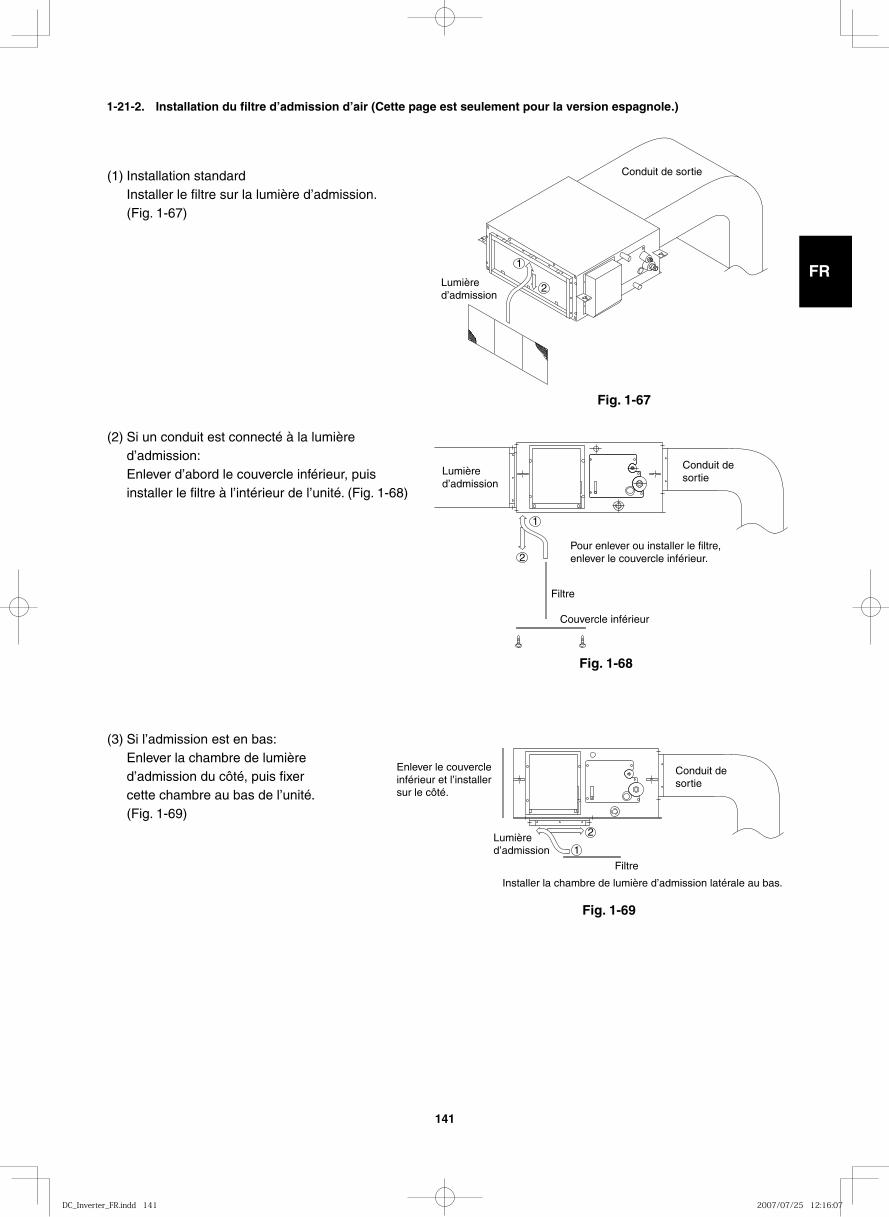
GB
FR
DE
IT
PT
GR
ES
141
(1) Installation standardInstaller le filtre sur la lumière d’admission. (Fig. 1-67)
(2) Si un conduit est connecté à la lumière d’admission:Enlever d’abord le couvercle inférieur, puis installer le filtre à l’intérieur de l’unité. (Fig. 1-68)
(3) Si l’admission est en bas:Enlever la chambre de lumière d’admission du côté, puis fixer cette chambre au bas de l’unité. (Fig. 1-69)
Conduit de sortie
Lumièred’admission
2
1
Conduit desortie
Lumièred’admission
2
1
Pour enlever ou installer le filtre,enlever le couvercle inférieur.
Filtre
Couvercle inférieur
Conduit desortie
Lumièred’admission
2
1
Installer la chambre de lumière d’admission latérale au bas.
Filtre
Enlever le couvercle inférieur et l’installersur le côté.
Fig. 1-67
Fig. 1-68
Fig. 1-69
1-21-2. Installation du filtre d’admission d’air (Cette page est seulement pour la version espagnole.)
DC_Inverter_FR.indd 141DC_Inverter_FR.indd 141 2007/07/25 12:16:072007/07/25 12:16:07
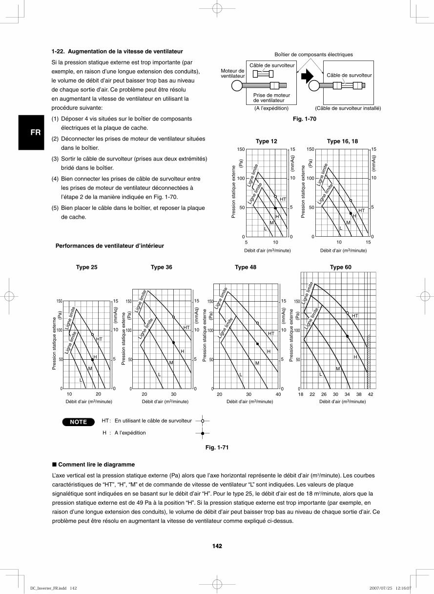
GB
FR
DE
IT
PT
GR
ES
142142
1-22. Augmentation de la vitesse de ventilateur
Si la pression statique externe est trop importante (par
exemple, en raison d’une longue extension des conduits),
le volume de débit d’air peut baisser trop bas au niveau
de chaque sortie d’air. Ce problème peut être résolu
en augmentant la vitesse de ventilateur en utilisant la
procédure suivante:
(1) Déposer 4 vis situées sur le boîtier de composants
électriques et la plaque de cache.
(2) Déconnecter les prises de moteur de ventilateur situées
dans le boîtier.
(3) Sortir le câble de survolteur (prises aux deux extrémités)
bridé dans le boîtier.
(4) Bien connecter les prises de câble de survolteur entre
les prises de moteur de ventilateur déconnectées à
l’étape 2 de la manière indiquée en Fig. 1-70.
(5) Bien placer le câble dans le boîtier, et reposer la plaque
de cache.
Fig. 1-70
Fig. 1-71
Moteur de ventilateur
Câble de survolteur
Prise de moteur de ventilateur
(A l’expédition)
Boîtier de composants électriques
(Câble de survolteur installé)
Câble de survolteur
■ Comment lire le diagramme
L’axe vertical est la pression statique externe (Pa) alors que l’axe horizontal représente le débit d’air (m3/minute). Les courbes
caractéristiques de “HT”, “H”, “M” et de commande de vitesse de ventilateur “L” sont indiquées. Les valeurs de plaque
signalétique sont indiquées en se basant sur le débit d’air “H”. Pour le type 25, le débit d’air est de 18 m3/minute, alors que la
pression statique externe est de 49 Pa à la position “H”. Si la pression statique externe est trop importante (par exemple, en
raison d’une longue extension des conduits), le volume de débit d’air peut baisser trop bas au niveau de chaque sortie d’air. Ce
problème peut être résolu en augmentant la vitesse de ventilateur comme expliqué ci-dessus.
5
Pre
ssio
n st
atiq
ue e
xter
ne0
50
100
0
5
10
15 150
10
(mm
Aq)
(Pa)
HT
H M
L
20
Pre
ssio
n st
atiq
ue e
xter
ne
0
50
0
5
10
15 150
10
HT
H
L
100
M
(mm
Aq)
(Pa)
30 40 18 22 26 30 34 38 42
Pre
ssio
n st
atiq
ue e
xter
ne
0
50
0
5
10
15 150
20
L
100
M
H
M
H
L
(mm
Aq)
(Pa)
Pre
ssio
n st
atiq
ue e
xter
ne
0
50
150
100
(Pa)
HT
HT
30
Pre
ssio
n st
atiq
ue e
xter
ne
0
50
0
5
10
15 150
20
HT
L
100
M
H
(mm
Aq)
(Pa)
15
Pre
ssio
n st
atiq
ue e
xter
ne
0
50
0
5
10
15 150
10
HT
M L
100
H
(mm
Aq)
(Pa)
Type 16, 18 Type 12
Performances de ventilateur d’intérieur
Type 25 Type 36 Type 48 Type 60
NOTE HT:
H :
En utilisant le câble de survolteur
A l’expédition
Débit d’air (m3/minute) Débit d’air (m3/minute) Débit d’air (m3/minute) Débit d’air (m3/minute)
Lign
e lim
iteLi
gne
limite Li
gne
limite
Lign
e lim
ite
Débit d’air (m3/minute) Débit d’air (m3/minute)
Lign
e lim
ite
Lign
e lim
ite
Lign
e lim
iteLi
gne
limite
Lign
e lim
iteLi
gne
limite
Lign
e lim
iteLi
gne
limite
DC_Inverter_FR.indd 142DC_Inverter_FR.indd 142 2007/07/25 12:16:072007/07/25 12:16:07
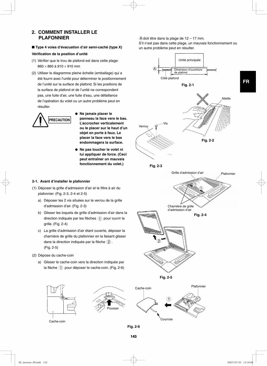
GB
FR
DE
IT
PT
GR
ES
143143
2. COMMENT INSTALLER LE PLAFONNIER
■ Type 4 voies d’évacuation d’air semi-caché (type X)
Vérification de la position d’unité
(1) Vérifier que le trou de plafond est dans cette plage:
860 × 860 à 910 × 910 mm
(2) Utiliser le diagramme pleine échelle (emballage) qui a
été fourni avec l’unité pour déterminer le positionnement
de l’unité sur la surface de plafond. Si les positions de
la surface de plafond et de l’unité ne correspondent
pas, une fuite d’air, une fuite d’eau, une défaillance
de l’opération du volet ou un autre problème peut en
résulter.
PRECAUTION
● Ne jamais placer le panneau la face vers le bas. L’accrocher verticalement ou le placer sur le haut d’un objet en porte à faux. Le placer la face vers le bas endommagera la surface.
● Ne pas toucher le volet ni lui appliquer de force. (Ceci peut entraîner un mauvais fonctionnement du volet.)
A doit être dans la plage de 12 – 17 mm.S’il n’est pas dans cette plage, un mauvais fonctionnement ou un autre problème peut en résulter.
A
Unité principale
Dimension dʼouverture de plafond
Côté plafond
Fig. 2-1
Ailette
Fig. 2-2
Fig. 2-3
2
Fig. 2-5
2-1. Avant d’installer le plafonnier
(1) Déposer la grille d’admission d’air et le filtre à air du
plafonnier. (Fig. 2-3, 2-4 et 2-5)
a) Déposer les 2 vis situées sur le verrou de la grille
d’admission d’air. (Fig. 2-3)
b) Glisser les loquets de grille d’admission d’air dans la
direction indiquée par les flèches 1 pour ouvrir la
grille. (Fig. 2-4)
c) La grille d’admission d’air étant ouverte, déposer la
charnière de grille du plafonnier en la faisant glisser
dans la direction indiquée par la flèche 2 .
(Fig. 2-5)
(2) Dépose du cache-coin
a) Glisser le cache-coin vers la direction indiquée par
la flèche 1 pour déposer le cache-coin. (Fig. 2-6)
1
Cache-coin
Pousser
Cache-coin
Courroie
Plafonnier
Fig. 2-6
11
Grille dʼadmission dʼair Plafonnier
Charnière de grille dʼadmission dʼair
Fig. 2-4
VerrouVis
DC_Inverter_FR.indd 143DC_Inverter_FR.indd 143 2007/07/25 12:16:082007/07/25 12:16:08
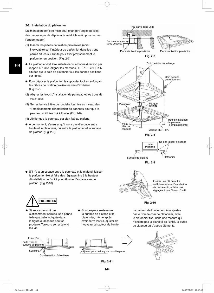
GB
FR
DE
IT
PT
GR
ES
144144
PRECAUTION
2-2. Installation du plafonnier
L’alimentation doit être mise pour changer l’angle du volet.
(Ne pas essayer de déplacer le volet à la main pour ne pas
l’endommager.)
(1) Insérer les pièces de fixation provisoires (acier
inoxydable) sur l’intérieur du plafonnier dans les trous
carrés situés sur l’unité pour fixer provisoirement le
plafonnier en position. (Fig. 2-7)
● Le plafonnier doit être installé dans la bonne direction par rapport à l’unité. Aligner les marques REF.PIPE et DRAIN situées sur le coin de plafonnier sur les bonnes positions sur l’unité.
● Pour déposer le plafonnier, le supporter tout en enfonçant les pièces de fixation provisoires vers l’extérieur. (Fig. 2-7)
(2) Aligner les trous d’installation de panneau et les trous de
vis d’unité.
(3) Serrer les vis à tête de rondelle fournies au niveau des
4 emplacements d’installation de panneau pour que le
panneau soit bien fixé à l’unité. (Fig. 2-8)
(4) Vérifier que le panneau est bien fixé au plafond.
● A ce moment, s’assurer qu’il n’y a pas d’espace entre l’unité et le plafonnier, ou entre le plafonnier et la surface de plafond. (Fig. 2-9)
● S’il n’y a un espace entre le panneau et le plafond, laisser le plafonnier fixé et faire des réglages fins à la hauteur d’installation de l’unité pour éliminer l’espace avec le plafond. (Fig. 2-10)
Pousser lorsque vous déposez
Trou carré dans unité
Pièce de fixation provisoire Pièce de fixation provisoire
Fig. 2-7
Coin de tube de vidange
Coin de tube de réfrigérant
Marque DRAIN
Trou dʼinstallation de panneau (4 emplacements)
Marque REF.PIPE
Vis à tête de rondelle
Plafonnier
Fig. 2-8
Surface de plafond
Unité principale
Ne pas laisser dʼespace
Plafonnier
Fig. 2-9
Insérer une clé ou autre outil dans le trou dʼinstallation de cache-coin, et faire des réglages fins à lʼécrou dʼunité.
Fuite dʼair
Fuite dʼair de surface de plafond
Souillure
Condensation, fuite dʼeau
Ajuster pour quʼil nʼy air pas dʼespace.
Fig. 2-10
Fig. 2-11
● Si les vis ne sont pas suffisamment serrées, une panne telle que celle indiquée dans la figure ci-dessous peut se produire. Toujours serrer à fond les vis.
● Si un espace reste entre la surface de plafond et le plafonnier, même après avoir serré les vis, ajuster de nouveau la hauteur de l’unité.
La hauteur de l’unité peut être ajustée par le trou de coin de plafonnier, avec le plafonnier fixé, dans une mesure qui n’affecte pas la planéité de l’unité, la durite de vidange ou d’autres éléments.
DC_Inverter_FR.indd 144DC_Inverter_FR.indd 144 2007/07/25 12:16:082007/07/25 12:16:08
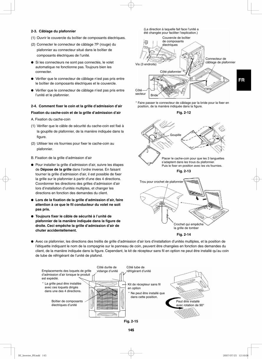
GB
FR
DE
IT
PT
GR
ES
145145
2-3. Câblage du plafonnier
(1) Ouvrir le couvercle du boîtier de composants électriques.
(2) Connecter le connecteur de câblage 7P (rouge) du
plafonnier au connecteur situé dans le boîtier de
composants électriques de l’unité.
● Si les connecteurs ne sont pas connectés, le volet automatique ne fonctionne pas. Toujours bien les connecter.
● Vérifier que le connecteur de câblage n’est pas pris entre le boîtier de composants électriques et le couvercle.
● Vérifier que le connecteur de câblage n’est pas pris entre l’unité et le plafonnier.
2-4. Comment fixer le coin et la grille d’admission d’air
Fixation du cache-coin et de la grille d’admission d’air
A. Fixation du cache-coin
(1) Vérifier que le câble de sécurité du cache-coin est fixé à
la goupille de plafonnier, de la manière indiquée dans la
figure.
(2) Utiliser les vis fournies pour fixer le cache-coin au
plafonnier.
B. Fixation de la grille d’admission d’air
● Pour installer la grille d’admission d’air, suivre les étapes de Dépose de la grille dans l’ordre inverse. En faisant tourner la grille d’admission d’air, il est possible de fixer la grille sur le plafonnier à partir d’une des 4 directions. Coordonner les directions des grilles d’admission d’air lors d’installation d’unités multiples, et changer les directions en fonction des demandes du client.
● Lors de la fixation de la grille d’admission d’air, faire attention à ce que le fil conducteur du volet ne soit pas pris.
● Toujours fixer le câble de sécurité à l’unité de plafonnier de la manière indiquée dans la figure de droite. Ceci empêche la grille d’admission d’air de chuter accidentellement.
(La direction à laquelle fait face l’unité a été changée pour faciliter l’explication.)
Couvercle de boîtier de composants électriques
Vis (3 endroits)
Côté plafonnier
Connecteur de câblage de plafonnier
Bride
Côté secteur
Faire passer le connecteur de câblage par la bride pour la fixer en position, de la manière indiquée dans la figure.
*
Goupille
Placer le cache-coin pour que les 3 languettes sʼadaptent dans les trous du plafonnier. Puis le fixer en position avec les vis fournies.
● Avec ce plafonnier, les directions des treillis de grille d’admission d’air lors d’installation d’unités multiples, et la position de l’étiquette indiquant le nom de la compagnie sur le panneau de coin, peuvent être changées en fonction des demandes du client, de la manière indiquée dans la figure. Cependant, le kit de récepteur sans fil en option ne peut être installé qu’au coin de tube de réfrigérant de l’unité de plafond.
Emplacements des loquets de grille dʼadmission dʼair lorsque le produit est expédié.
La grille peut être installée avec ces loquets dirigés dans une des 4 directions.
* Kit de récepteur sans fil en option
Ne peut être installé que dans cette position.
*
Côté durite de vidange dʼunité
Côté tube de réfrigérant dʼunité
Peut être installé avec rotation de 90°
Boîtier de composants électriques dʼunité
Fig. 2-12
Fig. 2-13
Trou pour crochet de plafonnier
Crochet qui empêche la grille de tomber
Fig. 2-14
Fig. 2-15
DC_Inverter_FR.indd 145DC_Inverter_FR.indd 145 2007/07/25 12:16:082007/07/25 12:16:08
GB
FR
DE
IT
PT
GR
ES
146146
2-5. Vérification après installation
● Vérifier qu’il n’y a pas d’espaces entre l’unité et le plafonnier, ou entre le plafonnier et la surface de plafond. Les espaces peuvent entraîner une fuite d’eau et de la condensation.
● Vérifier que le câblage est bien connecté.S’il n’est pas bien connecté, le volet automatique ne fonctionnera pas. (“P09” est affiché sur la télécommande.) En outre, une fuite d’eau et de la condensation peuvent se produire.
2-6. Lors de la dépose du plafonnier pour entretien
Lors de la dépose du plafonnier pour entretien, déposer
la grille d’admission d’air et le filtre à air, déconnecter le
connecteur de câblage à l’intérieur du boîtier de composants
électriques, puis déposer les 4 vis de fixation.
2-7. Réglage du volet automatique
L’ailette de direction d’air située sur la sortie de plafonnier
peut être ajustée comme suit.
● Ajuster l’ailette à l’angle désiré en utilisant la télécommande. L’ailette a également un mécanisme de balayage d’air automatique.
NOTE
● Ne jamais essayer de déplacer l’ailette à la main.
● Un bon passage d’air dépend de l’emplacement du climatiseur, de la disposition de la pièce et du mobilier, etc. Si le refroidissement ou le chauffage semble inadéquat, essayer de changer la direction du passage d’air.
DC_Inverter_FR.indd 146DC_Inverter_FR.indd 146 2007/07/25 12:16:082007/07/25 12:16:08
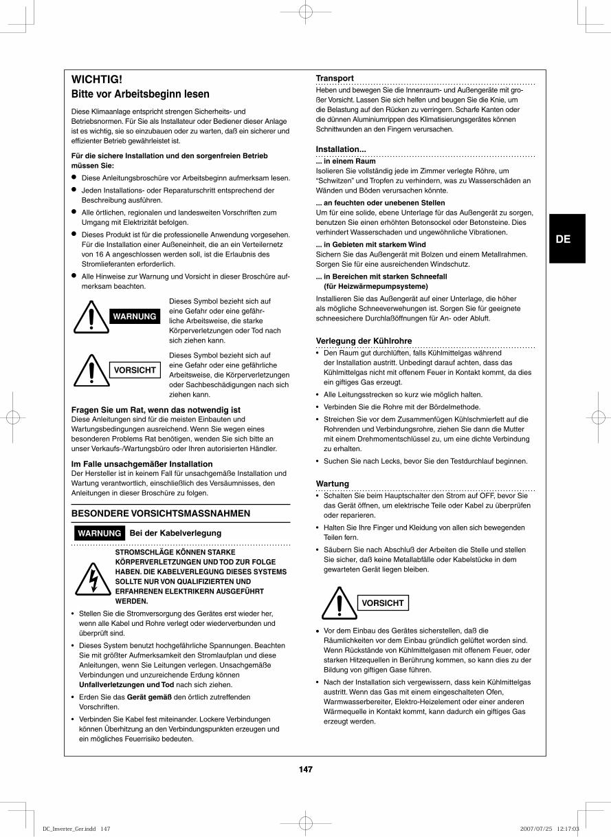
GB
FR
DE
IT
PT
GR
ES
147147
WICH TIG!Bitte vor Arbeitsbeginn lesen
Diese Klimaanlage ent spricht stren gen Sicherheits- und Betriebsnormen. Für Sie als Installateur oder Bediener die ser Anlage ist es wich tig, sie so ein zu bau en oder zu war ten, daß ein siche rer und effi zien ter Betrieb gewähr lei stet ist.
Für die siche re Installation und den sor gen freien Betrieb müs sen Sie:
● Diese Anleitungsbroschüre vor Arbeitsbeginn auf merk sam lesen.
● Jeden Installations- oder Reparaturschritt ent spre chend der Beschreibung aus füh ren.
● Alle ört li chen, regio na len und lan des wei ten Vorschriften zum Umgang mit Elektrizität befol gen.
● Dieses Produkt ist für die professionelle Anwendung vorgesehen. Für die Installation einer Außeneinheit, die an ein Verteilernetz
von 16 A angeschlossen werden soll, ist die Erlaubnis des Stromlieferanten erforderlich.
● Alle Hinweise zur Warnung und Vorsicht in die ser Broschüre auf-merk sam beach ten.
Dieses Symbol bezieht sich auf eine Gefahr oder eine gefähr-li che Arbeitsweise, die star ke Körperverletzungen oder Tod nach sich zie hen kann.
Dieses Symbol bezieht sich auf eine Gefahr oder eine gefähr li che Arbeitsweise, die Körperverletzungen oder Sachbeschädigungen nach sich zie hen kann.
Fragen Sie um Rat, wenn das not wen dig istDiese Anleitungen sind für die mei sten Einbauten und Wartungsbedingungen aus rei chend. Wenn Sie wegen eines beson de ren Problems Rat benö ti gen, wen den Sie sich bitte an unser Verkaufs-/Wartungsbüro oder Ihren auto ri sier ten Händler.
Im Falle unsach ge mä ßer InstallationDer Hersteller ist in kei nem Fall für unsach ge mä ße Installation und Wartung ver ant wort lich, ein schließ lich des Versäumnisses, den Anleitungen in die ser Broschüre zu fol gen.
BESON DE RE VOR SICHTS MASS NAH MEN
WARNUNG Bei der Kabelverlegung
STROM SCHLÄ GE KÖN NEN STAR KE KÖR PER VER LET ZUN GEN UND TOD ZUR FOLGE HABEN. DIE KABEL VER LE GUNG DIE SES SYSTEMS SOLL TE NUR VON QUA LI FI ZIER TEN UND ERFAH RE NEN ELEK TRI KERN AUS GE FÜHRT WER DEN.
• Stellen Sie die Stromversorgung des Gerätes erst wie der her, wenn alle Kabel und Rohre ver legt oder wie der ver bun den und über prüft sind.
• Dieses System benutzt hoch ge fähr li che Spannungen. Beachten Sie mit größ ter Aufmerksamkeit den Stromlaufplan und diese Anleitungen, wenn Sie Leitungen ver le gen. Unsachgemäße Verbindungen und unzu rei chen de Erdung kön nen Unfallverletzungen und Tod nach sich zie hen.
• Erden Sie das Gerät gemäß den ört lich zutref fen den Vorschriften.
• Verbinden Sie Kabel fest mit ein an der. Lockere Verbindungen kön nen Überhitzung an den Verbindungspunkten erzeu gen und ein mög li ches Feuerrisiko bedeu ten.
TransportHeben und bewe gen Sie die Innenraum- und Außengeräte mit gro-ßer Vorsicht. Lassen Sie sich hel fen und beu gen Sie die Knie, um die Belastung auf den Rücken zu ver rin gern. Scharfe Kanten oder die dün nen Aluminiumrippen des Klimatisierungsgerätes kön nen Schnittwunden an den Fingern ver ur sa chen.
Installation...... in einem RaumIsolieren Sie voll stän dig jede im Zimmer ver leg te Röhre, um “Schwitzen” und Tropfen zu ver hin dern, was zu Wasserschäden an Wänden und Böden ver ur sa chen könn te.
... an feuch ten oder unebe nen StellenUm für eine soli de, ebene Unterlage für das Außengerät zu sor gen, benut zen Sie einen erhöh ten Betonsockel oder Betonsteine. Dies ver hin dert Wasserschaden und unge wöhn li che Vibrationen.
... in Gebieten mit star kem WindSichern Sie das Außengerät mit Bolzen und einem Metallrahmen. Sorgen Sie für eine aus rei chen den Windschutz.
... in Bereichen mit star ken Schneefall (für Heizwärmepumpsysteme)
Installieren Sie das Außengerät auf einer Unterlage, die höher als mög li che Schneeverwehungen ist. Sorgen Sie für geeig ne te schnee si che re Durchlaßöffnungen für An- oder Abluft.
Verlegung der Kühlrohre• Den Raum gut durchlüften, falls Kühlmittelgas während
der Installation austritt. Unbedingt darauf achten, dass das Kühlmittelgas nicht mit offenem Feuer in Kontakt kommt, da dies ein giftiges Gas erzeugt.
• Alle Leitungsstrecken so kurz wie möglich halten.
• Verbinden Sie die Rohre mit der Bördelmethode.
• Streichen Sie vor dem Zusammenfügen Kühlschmierfett auf die Rohrenden und Verbindungsrohre, zie hen Sie dann die Mutter mit einem Drehmomentschlüssel zu, um eine dich te Verbindung zu erhal ten.
• Suchen Sie nach Lecks, bevor Sie den Testdurchlauf begin nen.
Wartung• Schalten Sie beim Hauptschalter den Strom auf OFF, bevor Sie
das Gerät öff nen, um elek tri sche Teile oder Kabel zu über prü fen oder repa rie ren.
• Halten Sie Ihre Finger und Kleidung von allen sich bewe gen den Teilen fern.
• Säubern Sie nach Abschluß der Arbeiten die Stelle und stel len Sie sicher, daß keine Metallabfälle oder Kabelstücke in dem gewar te ten Gerät lie gen blei ben.
• Vor dem Einbau des Gerätes sicher stel len, daß die Räumlichkeiten vor dem Einbau gründ lich gelüf tet wor den sind. Wenn Rückstände von Kühlmittelgasen mit offe nem Feuer, oder star ken Hitzequellen in Berührung kom men, so kann dies zu der Bildung von gif ti gen Gase füh ren.
• Nach der Installation sich vergewissern, dass kein Kühlmittelgas austritt. Wenn das Gas mit einem eingeschalteten Ofen, Warmwasserbereiter, Elektro-Heizelement oder einer anderen Wärmequelle in Kontakt kommt, kann dadurch ein giftiges Gas erzeugt werden.
WARNUNG
VORSICHT
VORSICHT
DC_Inverter_Ger.indd 147DC_Inverter_Ger.indd 147 2007/07/25 12:17:032007/07/25 12:17:03
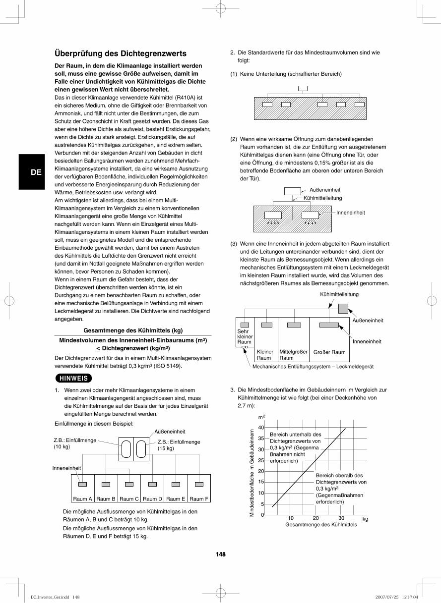
GB
FR
DE
IT
PT
GR
ES
148148
2. Die Standardwerte für das Mindestraumvolumen sind wie folgt:
(1) Keine Unterteilung (schraffierter Bereich)
(2) Wenn eine wirksame Öffnung zum danebenliegenden Raum vorhanden ist, die zur Entlüftung von ausgetretenem Kühlmittelgas dienen kann (eine Öffnung ohne Tür, oder eine Öffnung, die mindestens 0,15% größer ist als die betreffende Bodenfläche am oberen oder unteren Bereich der Tür).
(3) Wenn eine Inneneinheit in jedem abgeteilten Raum installiert und die Leitungen untereinander verbunden sind, dient der kleinste Raum als Bemessungsobjekt. Wenn allerdings ein mechanisches Entlüftungssystem mit einem Leckmeldegerät im kleinsten Raum installiert wurde, wird das Volumen des nächstgrößeren Raumes als Bemessungsobjekt genommen.
3. Die Mindestbodenfläche im Gebäudeinnern im Vergleich zur Kühlmittelmenge ist wie folgt (bei einer Deckenhöhe von 2,7 m):
Überprüfung des DichtegrenzwertsDer Raum, in dem die Klimaanlage installiert werden soll, muss eine gewisse Größe aufweisen, damit im Falle einer Undichtigkeit von Kühlmittelgas die Dichte einen gewissen Wert nicht überschreitet.Das in dieser Klimaanlage verwendete Kühlmittel (R410A) ist ein sicheres Medium, ohne die Giftigkeit oder Brennbarkeit von Ammoniak, und fällt nicht unter die Bestimmungen, die zum Schutz der Ozonschicht in Kraft gesetzt wurden. Da dieses Gas aber eine höhere Dichte als aufweist, besteht Erstickungsgefahr, wenn die Dichte zu stark ansteigt. Erstickungsfälle, die auf austretendes Kühlmittelgas zurückgehen, sind extrem selten. Verbunden mit der steigenden Anzahl von Gebäuden in dicht besiedelten Ballungsräumen werden zunehmend Mehrfach-Klimaanlagensysteme installiert, da eine wirksame Ausnutzung der verfügbaren Bodenfläche, individuellen Regelmöglichkeiten und verbesserte Energieeinsparung durch Reduzierung der Wärme, Betriebskosten usw. verlangt wird.Am wichtigsten ist allerdings, dass bei einem Multi-Klimaanlagensystem im Vergleich zu einem konventionellen Klimaanlagengerät eine große Menge von Kühlmittel nachgefüllt werden kann. Wenn ein Einzelgerät eines Multi-Klimaanlagensystems in einem kleinen Raum installiert werden soll, muss ein geeignetes Modell und die entsprechende Einbaumethode gewählt werden, damit bei einem Austreten des Kühlmittels die Luftdichte den Grenzwert nicht erreicht (und damit im Notfall geeignete Maßnahmen ergriffen werden können, bevor Personen zu Schaden kommen).Wenn in einem Raum die Gefahr besteht, dass der Dichtegrenzwert überschritten werden könnte, ist ein Durchgang zu einem benachbarten Raum zu schaffen, oder eine mechanische Belüftungsanlage in Verbindung mit einem Leckmeldegerät zu installieren. Die Dichtwerte sind nachfolgend angegeben.
Gesamtmenge des Kühlmittels (kg)
Mindestvolumen des Inneneinheit-Einbauraums (m3) < Dichtegrenzwert (kg/m3)
Der Dichtegrenzwert für das in einem Multi-Klimaanlagensystem verwendete Kühlmittel beträgt 0,3 kg/m3 (ISO 5149).
HINWEIS
1. Wenn zwei oder mehr Klimaanlagensysteme in einem einzelnen Klimaanlagengerät angeschlossen sind, muss die Kühlmittelmenge auf der Basis der für jedes Einzelgerät eingefüllten Menge berechnet werden.
Einfüllmenge in diesem Beispiel:
Die mögliche Ausflussmenge von Kühlmittelgas in den Räumen A, B und C beträgt 10 kg.
Die mögliche Ausflussmenge von Kühlmittelgas in den Räumen D, E und F beträgt 15 kg.
Außeneinheit
Kühlmittelleitung
Inneneinheit
Z.B.: Einfüllmenge (10 kg)
Außeneinheit
Inneneinheit
Raum A Raum B Raum C Raum D Raum E Raum F
Z.B.: Einfüllmenge (15 kg)
Kühlmittelleitung
Außeneinheit
Sehr kleiner Raum Inneneinheit
Kleiner Raum
Mittelgroßer Raum
Großer Raum
Mechanisches Entlüftungssystem – Leckmeldegerät
40
35
30
25
20
15
10
5
0 10 20 30
Gesamtmenge des Kühlmittels
Min
dest
bode
nflä
che
im G
ebäu
dein
nern
m 2
kg
Bereich unterhalb des Dichtegrenzwerts von 0,3 kg/m3 (Gegenmaßnahmen nicht erforderlich)
Bereich oberalb des Dichtegrenzwerts von 0,3 kg/m3 (Gegenmaßnahmen erforderlich)
DC_Inverter_Ger.indd 148DC_Inverter_Ger.indd 148 2007/07/25 12:17:042007/07/25 12:17:04
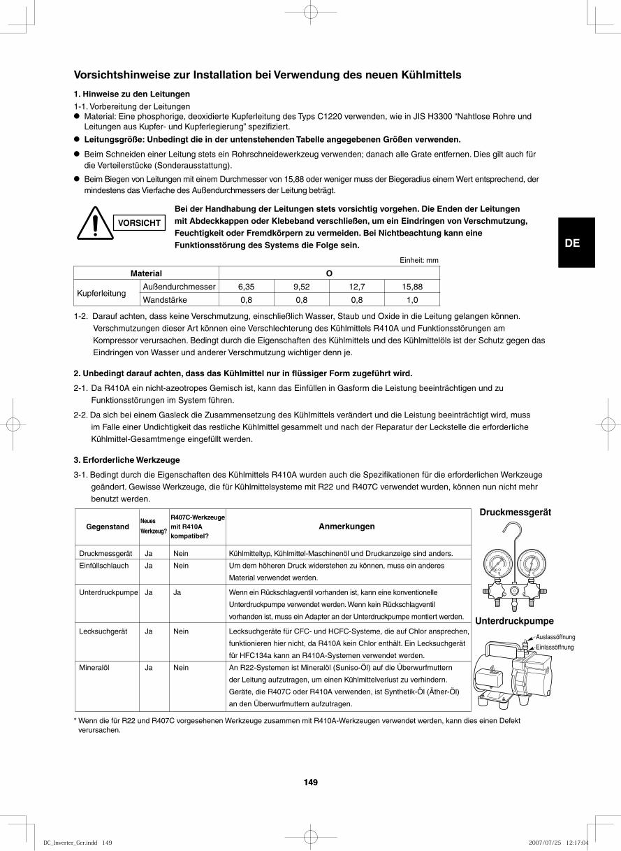
GB
FR
DE
IT
PT
GR
ES
149149
Druckmessgerät
Unterdruckpumpe
Auslassöffnung
Einlassöffnung
1-2. Darauf achten, dass keine Verschmutzung, einschließlich Wasser, Staub und Oxide in die Leitung gelangen können. Verschmutzungen dieser Art können eine Verschlechterung des Kühlmittels R410A und Funktionsstörungen am Kompressor verursachen. Bedingt durch die Eigenschaften des Kühlmittels und des Kühlmittelöls ist der Schutz gegen das
Eindringen von Wasser und anderer Verschmutzung wichtiger denn je.
2. Unbedingt darauf achten, dass das Kühlmittel nur in flüssiger Form zugeführt wird.
2-1. Da R410A ein nicht-azeotropes Gemisch ist, kann das Einfüllen in Gasform die Leistung beeinträchtigen und zu Funktionsstörungen im System führen.
2-2. Da sich bei einem Gasleck die Zusammensetzung des Kühlmittels verändert und die Leistung beeinträchtigt wird, muss im Falle einer Undichtigkeit das restliche Kühlmittel gesammelt und nach der Reparatur der Leckstelle die erforderliche Kühlmittel-Gesamtmenge eingefüllt werden.
3. Erforderliche Werkzeuge
3-1. Bedingt durch die Eigenschaften des Kühlmittels R410A wurden auch die Spezifikationen für die erforderlichen Werkzeuge geändert. Gewisse Werkzeuge, die für Kühlmittelsysteme mit R22 und R407C verwendet wurden, können nun nicht mehr benutzt werden.
Vorsichtshinweise zur Installation bei Verwendung des neuen Kühlmittels
1. Hinweise zu den Leitungen
1-1. Vorbereitung der Leitungen● Material: Eine phosphorige, deoxidierte Kupferleitung des Typs C1220 verwenden, wie in JIS H3300 “Nahtlose Rohre und
Leitungen aus Kupfer- und Kupferlegierung” spezifiziert.
● Leitungsgröße: Unbedingt die in der untenstehenden Tabelle angegebenen Größen verwenden.
● Beim Schneiden einer Leitung stets ein Rohrschneidewerkzeug verwenden; danach alle Grate entfernen. Dies gilt auch für die Verteilerstücke (Sonderausstattung).
● Beim Biegen von Leitungen mit einem Durchmesser von 15,88 oder weniger muss der Biegeradius einem Wert entsprechend, der mindestens das Vierfache des Außendurchmessers der Leitung beträgt.
* Wenn die für R22 und R407C vorgesehenen Werkzeuge zusammen mit R410A-Werkzeugen verwendet werden, kann dies einen Defekt verursachen.
VORSICHT
Bei der Handhabung der Leitungen stets vorsichtig vorgehen. Die Enden der Leitungen mit Abdeckkappen oder Klebeband verschließen, um ein Eindringen von Verschmutzung, Feuchtigkeit oder Fremdkörpern zu vermeiden. Bei Nichtbeachtung kann eine Funktionsstörung des Systems die Folge sein.
Gegenstand Anmerkungen
Druckmessgerät Ja Nein Kühlmitteltyp, Kühlmittel-Maschinenöl und Druckanzeige sind anders.
Einfüllschlauch Ja Nein Um dem höheren Druck widerstehen zu können, muss ein anderes
Material verwendet werden.
Unterdruckpumpe Ja Ja Wenn ein Rückschlagventil vorhanden ist, kann eine konventionelle
Unterdruckpumpe verwendet werden. Wenn kein Rückschlagventil
vorhanden ist, muss ein Adapter an der Unterdruckpumpe montiert werden.
Lecksuchgerät Ja Nein Lecksuchgeräte für CFC- und HCFC-Systeme, die auf Chlor ansprechen,
funktionieren hier nicht, da R410A kein Chlor enthält. Ein Lecksuchgerät
für HFC134a kann an R410A-Systemen verwendet werden.
Mineralöl Ja Nein An R22-Systemen ist Mineralöl (Suniso-Öl) auf die Überwurfmuttern
der Leitung aufzutragen, um einen Kühlmittelverlust zu verhindern.
Geräte, die R407C oder R410A verwenden, ist Synthetik-Öl (Äther-Öl)
an den Überwurfmuttern aufzutragen.
R407C-Werkzeugemit R410Akompatibel?
Neues
Werkzeug?
Einheit: mm
Material O
KupferleitungAußendurchmesser 6,35 9,52 12,7 15,88
Wandstärke 0,8 0,8 0,8 1,0
DC_Inverter_Ger.indd 149DC_Inverter_Ger.indd 149 2007/07/25 12:17:042007/07/25 12:17:04
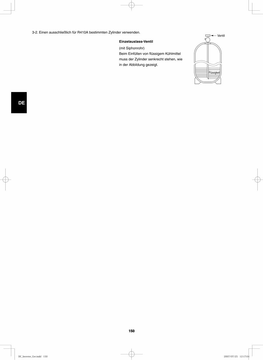
GB
FR
DE
IT
PT
GR
ES
150150
Ventil
Flüssigkeit
3-2. Einen ausschließlich für R410A bestimmten Zylinder verwenden.
Einzelauslass-Ventil
(mit Siphonrohr)
Beim Einfüllen von flüssigem Kühlmittel
muss der Zylinder senkrecht stehen, wie
in der Abbildung gezeigt.
DC_Inverter_Ger.indd 150DC_Inverter_Ger.indd 150 2007/07/25 12:17:042007/07/25 12:17:04
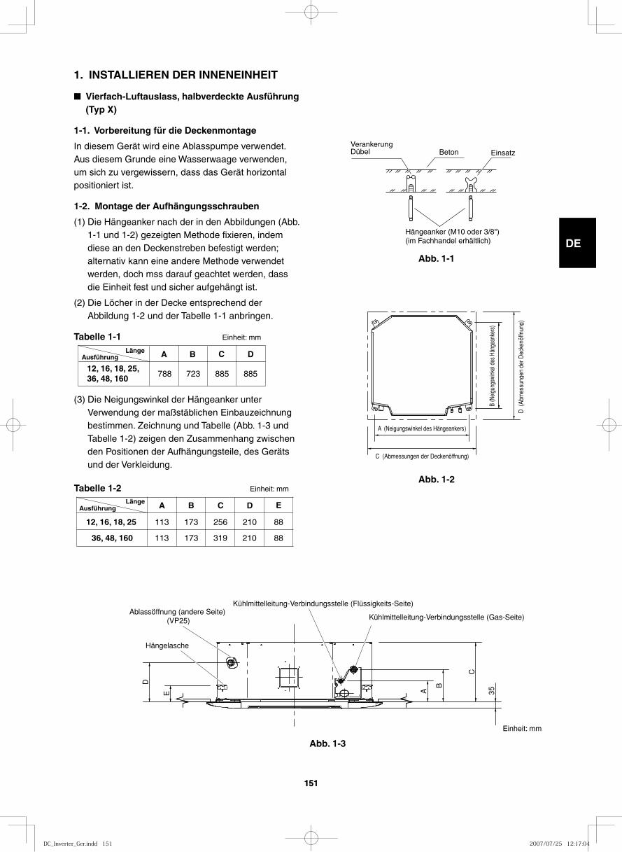
GB
FR
DE
IT
PT
GR
ES
151151
1. INSTALLIEREN DER INNENEINHEIT
■ Vierfach-Luftauslass, halbverdeckte Ausführung (Typ X)
1-1. Vorbereitung für die Deckenmontage
In diesem Gerät wird eine Ablasspumpe verwendet. Aus diesem Grunde eine Wasserwaage verwenden, um sich zu vergewissern, dass das Gerät horizontal positioniert ist.
1-2. Montage der Aufhängungsschrauben
(1) Die Hängeanker nach der in den Abbildungen (Abb. 1-1 und 1-2) gezeigten Methode fixieren, indem diese an den Deckenstreben befestigt werden; alternativ kann eine andere Methode verwendet werden, doch mss darauf geachtet werden, dass die Einheit fest und sicher aufgehängt ist.
(2) Die Löcher in der Decke entsprechend der Abbildung 1-2 und der Tabelle 1-1 anbringen.
Tabelle 1-1 Einheit: mm
(3) Die Neigungswinkel der Hängeanker unter Verwendung der maßstäblichen Einbauzeichnung bestimmen. Zeichnung und Tabelle (Abb. 1-3 und Tabelle 1-2) zeigen den Zusammenhang zwischen den Positionen der Aufhängungsteile, des Geräts und der Verkleidung.
Tabelle 1-2 Einheit: mm
Abb. 1-1
Abb. 1-2
Abb. 1-3
VerankerungDübel Beton Einsatz
Hängeanker (M10 oder 3/8")(im Fachhandel erhältlich)
Ausführung A B C D
788 723 885 885 12, 16, 18, 25,36, 48, 160
Länge
A B C D
113 173
173
210
210
256
36, 48, 160
12, 16, 18, 25
E
88
88 319 113
AusführungLänge
D (
Abm
essu
ngen
der
Dec
kenö
ffnun
g)
C (Abmessungen der Deckenöffnung)
A (Neigungswinkel des Hängeankers)
B (N
eigu
ngsw
inke
l des
Hän
gean
kers
)
E A
B
C
D
35
Hängelasche
Kühlmittelleitung-Verbindungsstelle (Flüssigkeits-Seite)
Kühlmittelleitung-Verbindungsstelle (Gas-Seite)(VP25)Ablassöffnung (andere Seite)
Einheit: mm
DC_Inverter_Ger.indd 151DC_Inverter_Ger.indd 151 2007/07/25 12:17:042007/07/25 12:17:04
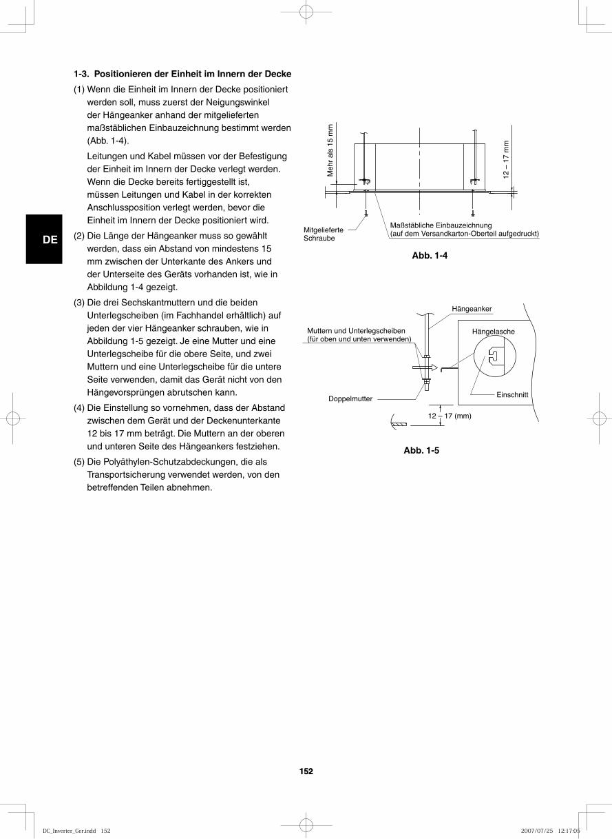
GB
FR
DE
IT
PT
GR
ES
152152
Abb. 1-4
Abb. 1-5
1-3. Positionieren der Einheit im Innern der Decke
(1) Wenn die Einheit im Innern der Decke positioniert werden soll, muss zuerst der Neigungswinkel der Hängeanker anhand der mitgelieferten maßstäblichen Einbauzeichnung bestimmt werden (Abb. 1-4).
Leitungen und Kabel müssen vor der Befestigung der Einheit im Innern der Decke verlegt werden. Wenn die Decke bereits fertiggestellt ist, müssen Leitungen und Kabel in der korrekten Anschlussposition verlegt werden, bevor die Einheit im Innern der Decke positioniert wird.
(2) Die Länge der Hängeanker muss so gewählt werden, dass ein Abstand von mindestens 15 mm zwischen der Unterkante des Ankers und der Unterseite des Geräts vorhanden ist, wie in Abbildung 1-4 gezeigt.
(3) Die drei Sechskantmuttern und die beiden Unterlegscheiben (im Fachhandel erhältlich) auf jeden der vier Hängeanker schrauben, wie in Abbildung 1-5 gezeigt. Je eine Mutter und eine Unterlegscheibe für die obere Seite, und zwei Muttern und eine Unterlegscheibe für die untere Seite verwenden, damit das Gerät nicht von den Hängevorsprüngen abrutschen kann.
(4) Die Einstellung so vornehmen, dass der Abstand zwischen dem Gerät und der Deckenunterkante 12 bis 17 mm beträgt. Die Muttern an der oberen und unteren Seite des Hängeankers festziehen.
(5) Die Polyäthylen-Schutzabdeckungen, die als Transportsicherung verwendet werden, von den betreffenden Teilen abnehmen.
Maßstäbliche Einbauzeichnung(auf dem Versandkarton-Oberteil aufgedruckt)Mitgelieferte
Schraube
Meh
r al
s 15
mm
12 –
17
mm
12 – 17 (mm)
Hängeanker
HängelascheMuttern und Unterlegscheiben (für oben und unten verwenden)
EinschnittDoppelmutter
DC_Inverter_Ger.indd 152DC_Inverter_Ger.indd 152 2007/07/25 12:17:052007/07/25 12:17:05
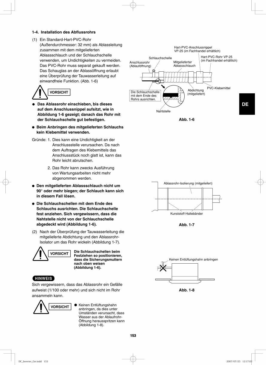
GB
FR
DE
IT
PT
GR
ES
153153
1-4. Installation des Abflussrohrs
(1) Ein Standard-Hart-PVC-Rohr (Außendurchmesser: 32 mm) als Ablassleitung zusammen mit dem mitgelieferten Ablassschlauch und der Schlauchschelle verwenden, um Undichtigkeiten zu vermeiden.Das PVC-Rohr muss separat gekauft werden. Das Schauglas an der Ablassöffnung erlaubt eine Überprüfung der Tauwasserleitung auf einwandfreie Funktion. (Abb. 1-6)
● Das Ablassrohr einschieben, bis dieses auf dem Anschlussnippel aufsitzt, wie in Abbildung 1-6 gezeigt; danach das Rohr mit der Schlauchschelle gut befestigen.
● Beim Anbringen des mitgelieferten Schlauchs kein Klebemittel verwenden.
Gründe: 1. Dies kann eine Undichtigkeit an der Anschlussstelle verursachen. Da nach dem Auftragen des Klebemittels das Anschlussstück noch glatt ist, kann das Rohr leicht abrutschen.
2. Das Rohr kann zwecks Ausführung von Wartungsarbeiten nicht mehr abgenommen werden.
● Den mitgelieferten Ablassschlauch nicht um 90° oder mehr biegen; der Schlauch kann sich in diesem Fall lösen.
● Die Schlauchschellen mit dem Ende des Schlauchs ausrichten. Die Schlauchschelle fest anziehen. Sich vergewissern, dass die Nahtstelle nicht von der Schlauchschelle abgedeckt wird (Abbildung 1-6).
(2) Nach der Überprüfung der Tauwasserleitung die mitgelieferte Abdichtung und den Ablassrohr-Isolator um das Rohr wickeln (Abbildung 1-7).
HINWEIS
Sich vergewissern, dass das Ablassrohr ein Gefälle aufweist (1/100 oder mehr) und sich nicht im Rohr ansammeln kann.
VORSICHT
VORSICHT Die Schlauchschellen beim Festziehen so positionieren, dass die Sicherungsmuttern nach oben weisen (Abbildung 1-6).
VORSICHT ● Keinen Entlüftungshahn anbringen, da dies unter Umständen verursacht, dass Wasser aus der Ablaufrohr-Öffnung herausspritzen kann (Abbildung 1-8).
Abb. 1-6
Abb. 1-7
Abb. 1-8
Nahtstelle
SchlauchschelleMitgelieferter Ablassschlauch
Anschlussrohr (Ablauföffnung)
Die Schlauchschelle mit dem Ende des Rohrs ausrichten.
Abdichtung (mitgeliefert)
Hart-PVC-Anschlussnippel VP-25 (im Fachhandel erhältlich)
Hart-PVC-Rohr VP-25 (im Fachhandel erhältlich)
PVC-Klebemittel
Kunststoff-Haltebänder
Ablassrohr-Isolierung (mitgeliefert)
Keinen Entlüftungshahn anbringen
DC_Inverter_Ger.indd 153DC_Inverter_Ger.indd 153 2007/07/25 12:17:052007/07/25 12:17:05
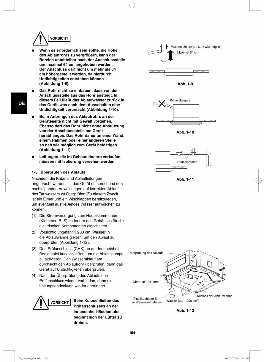
GB
FR
DE
IT
PT
GR
ES
154154
Abb. 1-9
Maximal 30 cm (so kurz wie möglich)
Maximal 64 cm
Abb. 1-10
Keine Steigung
Abb. 1-11
Abb. 1-12
Stützelemente
Wasser (ca. 1.200 cm3)
Mehr als 100 mm
Auslass der Ablaufwanne
Überprüfung des Ablaufs
Plastikbehälter für die Wasseraufnahmen
VORSICHT
● Wenn es erforderlich sein sollte, die Höhe des Ablaufrohrs zu vergrößern, kann der Bereich unmittelbar nach der Anschlussstelle um maximal 64 cm angehoben werden. Der Anschluss darf nicht um mehr als 64 cm höhergestellt werden, da hierdurch Undichtigkeiten entstehen können (Abbildung 1-9).
● Das Rohr nicht so einbauen, dass von der Anschlussstelle aus das Rohr ansteigt. In diesem Fall fließt das Ablaufwasser zurück in das Gerät, was nach dem Ausschalten eine Undichtigkeit verursacht (Abbildung 1-10).
● Beim Anbringen des Ablaufrohrs an der Geräteseite nicht mit Gewalt vorgehen. Ebenso darf das Rohr nicht ohne Abstützung von der Anschlussstelle am Gerät herabhängen. Das Rohr daher an einer Wand, einem Rahmen oder einer anderen Stelle so nah wie möglich zum Gerät befestigen (Abbildung 1-11).
● Leitungen, die im Gebäudeinnern verlaufen, müssen mit Isolierung versehen werden.
1-5. Überprüfen des Ablaufs
Nachdem die Kabel und Ablaufleitungen angebracht wurden, ist das Gerät entsprechend den nachfolgenden Anweisungen auf korrekten Ablauf des Tauwassers zu überprüfen. Zu diesem Zweck ist ein Eimer und ein Wischlappen bereitzulegen, um eventuell ausfließendes Wasser aufwischen zu können.
(1) Die Stromversorgung zum Hauptklemmenbrett (Klemmen R, S) im Innern des Gehäuses für die elektrischen Komponenten einschalten.
(2) Vorsichtig ungefähr 1.200 cm3 Wasser in die Ablaufwanne gießen, um den Ablauf zu überprüfen (Abbildung 1-12).
(3) Den Prüfanschluss (CHK) an der Inneneinheit-Bedientafel kurzschließen, um die Ablasspumpe zu aktivieren. Den Wasserablauf am durchsichtigen Ablaufrohr überprüfen, dann das Gerät auf Undichtigkeiten überprüfen.
(4) Nach der Überprüfung des Ablaufs den Prüfanschluss wieder verbinden, dann die Leitungsabdeckung wieder anbringen.
VORSICHT Beim Kurzschließen des Prüfanschlusses an der Inneneinheit-Bedientafel beginnt sich der Lüfter zu drehen.
DC_Inverter_Ger.indd 154DC_Inverter_Ger.indd 154 2007/07/25 12:17:052007/07/25 12:17:05
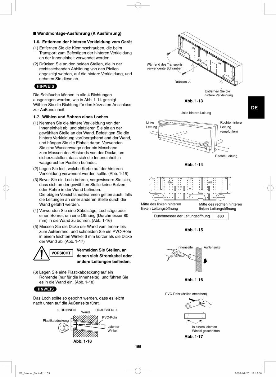
GB
FR
DE
IT
PT
GR
ES
155
■ Wandmontage-Ausführung (K Ausführung)
1-6. Entfernen der hinteren Verkleidung vom Gerät(1) Entfernen Sie die Klemmschrauben, die beim
Transport zum Befestigen der hinteren Verkleidung an der Inneneinheit verwendet werden.
(2) Drücken Sie an den beiden Stellen, die in der rechtsstehenden Abbildung von den Pfeilen angezeigt werden, auf die hintere Verkleidung, und nehmen Sie diese ab.
HINWEIS
Die Schläuche können in alle 4 Richtungen ausgezogen werden, wie in Abb. 1-14 gezeigt. Wählen Sie die Richtung für den kürzesten Anschluss zur Außeneinheit.
1-7. Wählen und Bohren eines Loches(1) Nehmen Sie die hintere Verkleidung von der
Inneneinheit ab, und platzieren Sie sie an der gewählten Stelle an der Wand. Befestigen Sie die hintere Verkleidung vorübergehend and der Wand, und hängen Sie die Einheit daran. Verwenden Sie eine Wasserwaage oder ein Messband zum Messen des Abstands von der Decke, um sicherzustellen, dass sich die Inneneinheit in waagerechter Position befindet.
(2) Legen Sie fest, welche Kerbe auf der hinteren Verkleidung verwendet werden sollte. (Abb. 1-15)
(3) Bevor Sie ein Loch bohren, vergewissern Sie sich, dass sich an der gewählten Stelle keine Bolzen oder Rohre in der Wand befinden.
Die obigen Vorsichtsmaßnahmen gelten auch, falls die Leitungen an einer anderen Stelle durch die Wand geführt werden.
(4) Verwenden Sie eine Säbelsäge, Lochsäge oder einen Bohrer, um eine Öffnung (Durchmesser 80 mm) in die Wand zu bohren. (Abb. 1-16)
(5) Messen Sie die Dicke der Wand vom Innen- bis zum Außenrand, und schneiden Sie ein PVC-Rohr in einem leichten Winkel 6 mm kürzer als die Dicke der Wand ab. (Abb. 1-17)
(6) Legen Sie eine Plastikabdeckung auf ein Rohrende (nur für die Innenseite), und führen Sie es in die Wand ein. (Abb. 1-18)
HINWEIS
Das Loch sollte so gebohrt werden, dass es leicht nach unten auf die Außenseite führt.
Abb. 1-13
Abb. 1-14
Abb. 1-15
Abb. 1-16
Abb. 1-17Abb. 1-18
VORSICHTVermeiden Sie Stellen, an denen sich Stromkabel oder andere Leitungen befinden.
Plastikabdeckung
DRINNENWand
LeichterWinkel
PVC-Rohr
DRAUSSEN
In einem leichtenWinkel geschnitten
PVC-Rohr (örtlich erworben)
Innenseite Außenseite
Mitte des linken hinteren linken Leitungsöffnung
Mitte des rechten hinteren linken Leitungsöffnung
Durchmesser der Leitungsöffnung ø80
LinkeLeitung
Rechte hintereLeitung(empfohlen)
Rechte Leitung
Linke hintere Leitung
Entfernen Sie die hintere Verkleidung
Drücken
Während des Transports verwendente Schrauben
DC_Inverter_Ger.indd 155DC_Inverter_Ger.indd 155 2007/07/25 12:17:062007/07/25 12:17:06
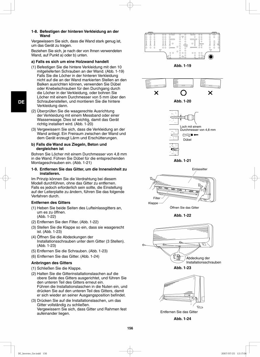
GB
FR
DE
IT
PT
GR
ES
156
Abb. 1-19
1-8. Befestigen der hinteren Verkleidung an der Wand
Vergewissern Sie sich, dass die Wand stark genug ist, um das Gerät zu tragen.Beziehen Sie sich, je nach der von Ihnen verwendeten Wand, auf Punkt a) oder b) unten.
a) Falls es sich um eine Holzwand handelt(1) Befestigen Sie die hintere Verkleidung mit den 10
mitgelieferten Schrauben an der Wand. (Abb. 1-19) Falls Sie die Löcher in der hinteren Verkleidung
nicht auf die an der Wand markierten Stellen an den Balken ausrichten können, verwenden Sie Dübel oder Knebelschrauben für den Durchgang durch die Löcher in der Verkleidung, oder bohren Sie Löcher mit einem Durchmesser von 5 mm über den Schraubenstellen, und montieren Sie die hintere Verkleidung dann.
(2) Überprüfen Sie die waagerechte Ausrichtung der Verkleidung mit einem Messband oder einer Wasserwaage. Dies ist wichtig, damit das Gerät richtig installiert wird. (Abb. 1-20)
(3) Vergewissern Sie sich, dass die Verkleidung an der Wand anliegt. Ein Freiraum zwischen der Wand und dem Gerät erzeugt Lärm und Erschütterungen.
b) Falls die Wand aus Ziegeln, Beton und dergleichen ist
Bohren Sie Löcher mit einem Durchmesser von 4,8 mm in die Wand. Führen Sie Dübel für die entsprechenden Montageschrauben ein. (Abb. 1-21)
1-9. Entfernen Sie das Gitter, um die Inneneinheit zu instalieren.
Im Prinzip können Sie die Verdrahtung bei diesem Modell durchführen, ohne das Gitter zu entfernen.Falls es jedoch erforderlich sein sollte, die Einstellung auf der Leiterplatte zu ändern, führen Sie das folgende Verfahren durch.
Entfernen des Gitters(1) Heben Sie beide Seiten des Lufteinlassgitters an,
um es zu öffnen.(Abb. 1-22)
(2) Entfernen Sie den Filter. (Abb. 1-22)(3) Stellen Sie die Klappe so ein, dass sie waagerecht
ist. (Abb. 1-23)(4) Öffnen Sie die Abdeckungen der
Installationsschrauben unter dem Gitter (3 Stellen). (Abb. 1-23)
(5) Entfernen Sie die Schrauben. (Abb. 1-23)(6) Entfernen Sie das Gitter. (Abb. 1-24)
Anbringen des Gitters(1) Schließen Sie die Klappe.(2) Halten Sie die Gitterinstallationslaschen auf die
obere Seite des Gitters ausgerichtet, und führen Sie den unteren Teil des Gitters erneut ein.
Führen die Installationslaschen in die Nuten ein, und drücken Sie auf den unteren Teil des Gitters, damit er sich wieder an seiner Ausgangsposition befindet.
(3) Drücken Sie auf die Installationslaschen, um das Gitter vollständig zu schließen.
Vergewissern Sie sich, dass Gitter und Rahmen fest aufeinander liegen.
Abb. 1-20
Abb. 1-21
Abb. 1-22
Abb. 1-23
Abb. 1-24
Loch mit einemDurchmesser von 4,8 mm
Dübel
Einlassitter
Filter
Klappe
Öffnen Sie das Gitter
Abdeckung der Installationsschrauben
Entfernen Sie das Gitter
DC_Inverter_Ger.indd 156DC_Inverter_Ger.indd 156 2007/07/25 12:17:062007/07/25 12:17:06
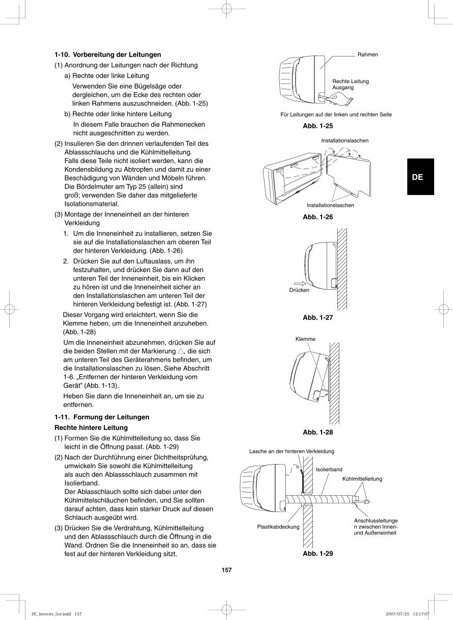
GB
FR
DE
IT
PT
GR
ES
157
1-10. Vorbereitung der Leitungen
(1) Anordnung der Leitungen nach der Richtung
a) Rechte oder linke Leitung
Verwenden Sie eine Bügelsäge oder dergleichen, um die Ecke des rechten oder linken Rahmens auszuschneiden. (Abb. 1-25)
b) Rechte oder linke hintere Leitung
In diesem Falle brauchen die Rahmenecken nicht ausgeschnitten zu werden.
(2) Insulieren Sie den drinnen verlaufenden Teil des Ablassschlauchs und die Kühlmittelleitung.
Falls diese Teile nicht isoliert werden, kann die Kondensbildung zu Abtropfen und damit zu einer Beschädigung von Wänden und Möbeln führen.
Die Bördelmuter am Typ 25 (allein) sind groß; verwenden Sie daher das mitgelieferte Isolationsmaterial.
(3) Montage der Inneneinheit an der hinteren Verkleidung
1. Um die Inneneinheit zu installieren, setzen Sie sie auf die Installationslaschen am oberen Teil der hinteren Verkleidung. (Abb. 1-26)
2. Drücken Sie auf den Luftauslass, um ihn festzuhalten, und drücken Sie dann auf den unteren Teil der Inneneinheit, bis ein Klicken zu hören ist und die Inneneinheit sicher an den Installationslaschen am unteren Teil der hinteren Verkleidung befestigt ist. (Abb. 1-27)
Dieser Vorgang wird erleichtert, wenn Sie die Klemme heben, um die Inneneinheit anzuheben. (Abb. 1-28)
Um die Inneneinheit abzunehmen, drücken Sie auf die beiden Stellen mit der Markierung ▲▲, die sich am unteren Teil des Geräterahmens befinden, um die Installationslaschen zu lösen. Siehe Abschritt 1-6. „Entfernen der hinteren Verkleidung vom Gerät” (Abb. 1-13).
Heben Sie dann die Inneneinheit an, um sie zu entfernen.
1-11. Formung der Leitungen
Rechte hintere Leitung
(1) Formen Sie die Kühlmittelleitung so, dass Sie leicht in die Öffnung passt. (Abb. 1-29)
(2) Nach der Durchführung einer Dichtheitsprüfung, umwickeln Sie sowohl die Kühlmittelleitung als auch den Ablassschlauch zusammen mit Isolierband.
Der Ablasschlauch sollte sich dabei unter den Kühlmittelschläuchen befinden, und Sie sollten darauf achten, dass kein starker Druck auf diesen Schlauch ausgeübt wird.
(3) Drücken Sie die Verdrahtung, Kühlmittelleitung und den Ablassschlauch durch die Öffnung in die Wand. Ordnen Sie die Inneneinheit so an, dass sie fest auf der hinteren Verkleidung sitzt.
Abb. 1-25
Rahmen
Rechte LeitungAusgang
Für Leitungen auf der linken und rechten Seite
Abb. 1-26
Installationslaschen
Installationslaschen
Abb. 1-27
Drücken
Abb. 1-28
Klemme
Abb. 1-29
Isolierband
Kühlmittelleitung
Lasche an der hinteren Verkleidung
PlastikabdeckungAnschlussleitungen zwischen Innen- und Außeneinheit
DC_Inverter_Ger.indd 157DC_Inverter_Ger.indd 157 2007/07/25 12:17:072007/07/25 12:17:07
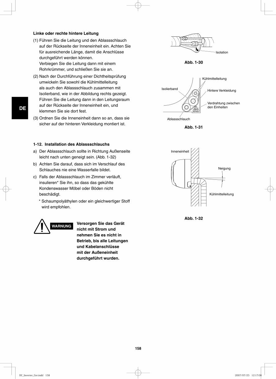
GB
FR
DE
IT
PT
GR
ES
158
Abb. 1-32
Abb. 1-30
Isolation
Abb. 1-31
Isolierband Hintere Verkleidung
Verdrahtung zwischenden Einheiten
Kühlmittelleitung
Ablassschlauch
Inneneinheit
Neigung
Kühlmittelleitung
1-12. Installation des Ablassschlauchs
a) Der Ablassschlauch sollte in Richtung Außenseite leicht nach unten geneigt sein. (Abb. 1-32)
b) Achten Sie darauf, dass sich im Verschlauf des Schlauches nie eine Wasserfalle bildet.
c) Falls der Ablassschlauch im Zimmer verläuft, insulieren* Sie ihn, so dass das gekühlte Kondenswasser Möbel oder Böden nicht beschädigt.
* Schaumpolyäthylen oder ein gleichwertiger Stoff wird empfohlen.
WARNUNGVersorgen Sie das Gerät nicht mit Strom und nehmen Sie es nicht in Betrieb, bis alle Leitungen und Kabelanschlüsse mit der Außeneinheit durchgeführt wurden.
Linke oder rechte hintere Leitung
(1) Führen Sie die Leitung und den Ablassschlauch auf der Rückseite der Inneneinheit ein. Achten Sie für ausreichende Länge, damit die Anschlüsse durchgeführt werden können.
Verbiegen Sie die Leitung dann mit einem Rohrkrümmer, und schließen Sie sie an.
(2) Nach der Durchführung einer Dichtheitsprüfung umwickeln Sie sowohl die Kühlmittelleitung als auch den Ablassschlauch zusammen mit Isolierband, wie in der Abbildung rechts gezeigt.
Führen Sie die Leitung dann in den Leitungsraum auf der Rückseite der Inneneinheit ein, und klemmen Sie sie dort fest.
(3) Ordnen Sie die Inneneinheit dann so an, dass sie sicher auf der hinteren Verkleidung montiert ist.
DC_Inverter_Ger.indd 158DC_Inverter_Ger.indd 158 2007/07/25 12:17:082007/07/25 12:17:08
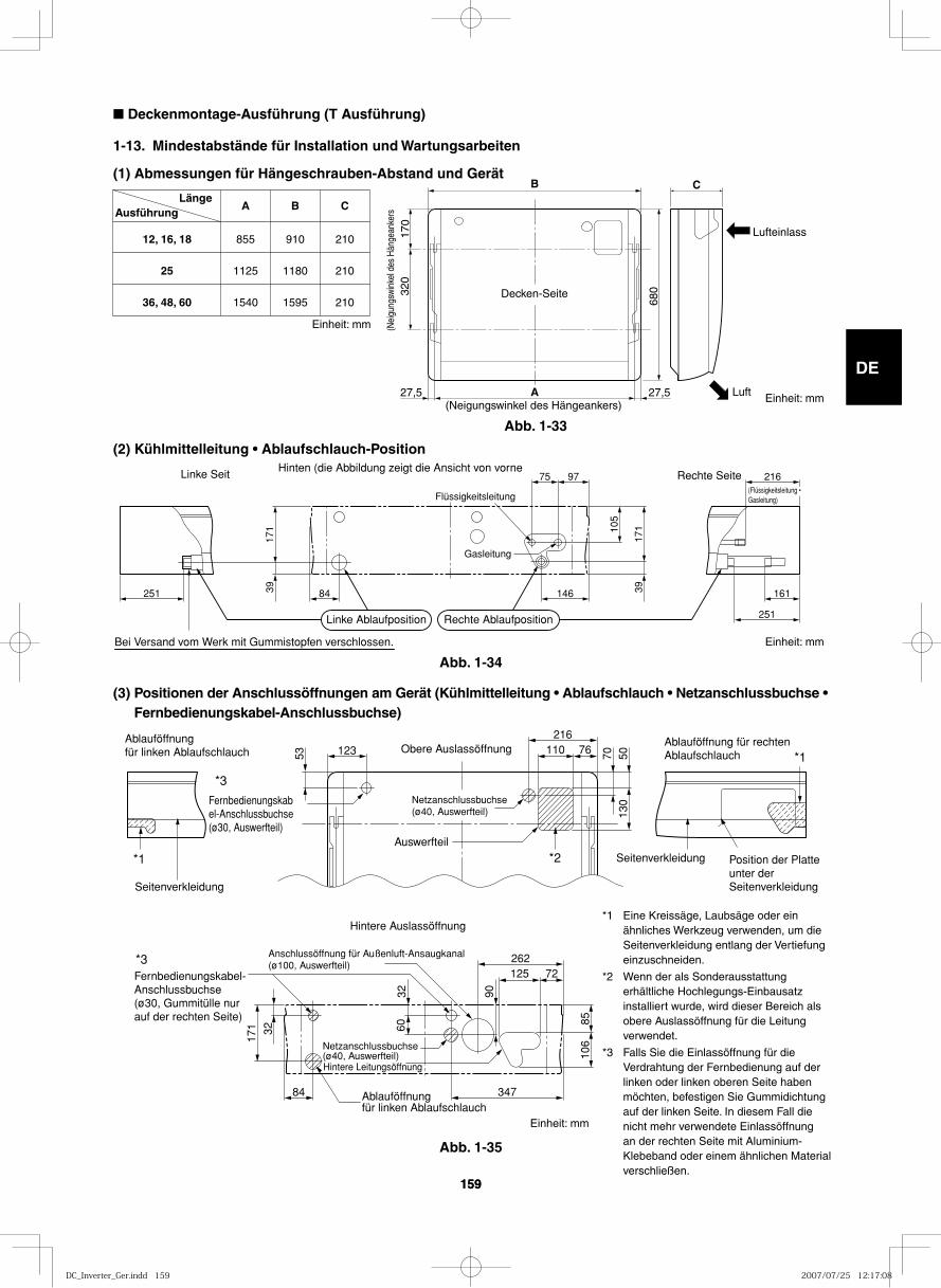
GB
FR
DE
IT
PT
GR
ES
159159
■ Deckenmontage-Ausführung (T Ausführung)
1-13. Mindestabstände für Installation und Wartungsarbeiten
(1) Abmessungen für Hängeschrauben-Abstand und Gerät
12, 16, 18
25
36, 48, 60
855
1125
1540
910
1180
1595
210
210
210
A B C Länge
Ausführung
B C
A 17
0 32
0
680
27,5 27,5
Decken-Seite
(Neigungswinkel des Hängeankers)
(Nei
gung
swin
kel d
es H
änge
anke
rs
Lufteinlass
Luft
(2) Kühlmittelleitung • Ablaufschlauch-Position
(3) Positionen der Anschlussöffnungen am Gerät (Kühlmittelleitung • Ablaufschlauch • Netzanschlussbuchse • Fernbedienungskabel-Anschlussbuchse)
251 84 146 161
75 97 216
39 39
171 10
5
171
251
Rechte SeiteLinke SeitHinten (die Abbildung zeigt die Ansicht von vorne
Bei Versand vom Werk mit Gummistopfen verschlossen.
Linke Ablaufposition Rechte Ablaufposition
Flüssigkeitsleitung
Gasleitung
(Flüssigkeitsleitung • Gasleitung)
53 70123 110 76216
5013
0
Ablauföffnung für linken Ablaufschlauch
Ablauföffnung für rechten AblaufschlauchObere Auslassöffnung
Fernbedienungskabel-Anschlussbuchse(ø30, Auswerfteil)
Netzanschlussbuchse(ø40, Auswerfteil)
Netzanschlussbuchse(ø40, Auswerfteil)
Auswerfteil
Seitenverkleidung
Position der Platte unter der Seitenverkleidung
Seitenverkleidung
Ablauföffnung für linken Ablaufschlauch
Hintere Leitungsöffnung
84
32
3260
171
347
125 72
8510
6
90
262
Fernbedienungskabel-Anschlussbuchse(ø30, Gummitülle nur auf der rechten Seite)
Anschlussöffnung für Außenluft-Ansaugkanal (ø100, Auswerfteil)
Hintere Auslassöffnung
*3
*1
*1
*2
*3
Abb. 1-33
Abb. 1-35
Abb. 1-34
Einheit: mm
Einheit: mm
Einheit: mm
*1 Eine Kreissäge, Laubsäge oder ein ähnliches Werkzeug verwenden, um die Seitenverkleidung entlang der Vertiefung einzuschneiden.
*2 Wenn der als Sonderausstattung erhältliche Hochlegungs-Einbausatz installiert wurde, wird dieser Bereich als obere Auslassöffnung für die Leitung verwendet.
*3 Falls Sie die Einlassöffnung für die Verdrahtung der Fernbedienung auf der linken oder linken oberen Seite haben möchten, befestigen Sie Gummidichtung auf der linken Seite. In diesem Fall die nicht mehr verwendete Einlassöffnung an der rechten Seite mit Aluminium-Klebeband oder einem ähnlichen Material verschließen.
Einheit: mm
DC_Inverter_Ger.indd 159DC_Inverter_Ger.indd 159 2007/07/25 12:17:082007/07/25 12:17:08
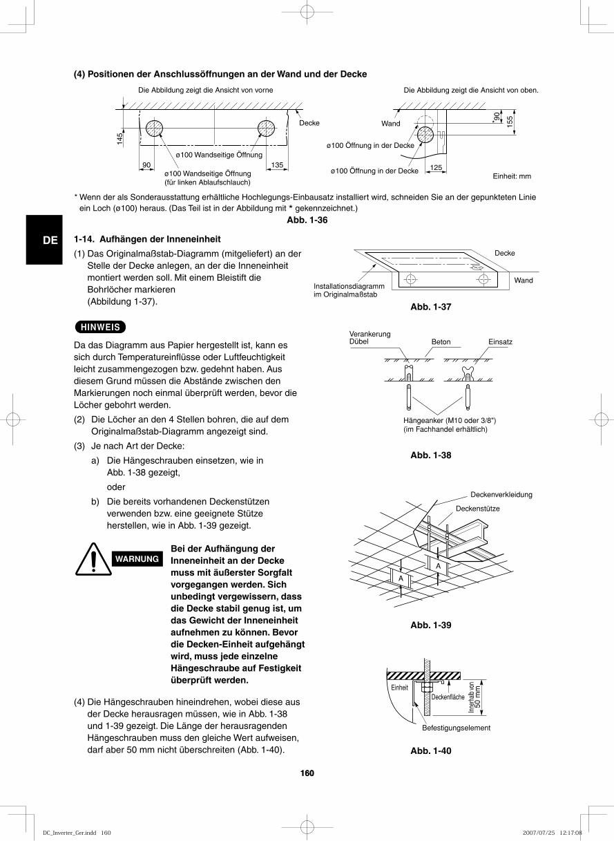
GB
FR
DE
IT
PT
GR
ES
160160
(4) Positionen der Anschlussöffnungen an der Wand und der Decke
90
145
135 125
155 90
*
Die Abbildung zeigt die Ansicht von vorne Die Abbildung zeigt die Ansicht von oben.
ø100 Wandseitige Öffnung (für linken Ablaufschlauch)
ø100 Wandseitige Öffnung ø100 Öffnung in der Decke
ø100 Öffnung in der Decke
Wand Decke
Installationsdiagramm im Originalmaßstab
Wand
Decke
Abb. 1-37
Abb. 1-36
Abb. 1-38
1-14. Aufhängen der Inneneinheit
(1) Das Originalmaßstab-Diagramm (mitgeliefert) an der Stelle der Decke anlegen, an der die Inneneinheit montiert werden soll. Mit einem Bleistift die Bohrlöcher markieren (Abbildung 1-37).
HINWEIS
Da das Diagramm aus Papier hergestellt ist, kann es sich durch Temperatureinflüsse oder Luftfeuchtigkeit leicht zusammengezogen bzw. gedehnt haben. Aus diesem Grund müssen die Abstände zwischen den Markierungen noch einmal überprüft werden, bevor die Löcher gebohrt werden.
(2) Die Löcher an den 4 Stellen bohren, die auf dem Originalmaßstab-Diagramm angezeigt sind.
(3) Je nach Art der Decke:
a) Die Hängeschrauben einsetzen, wie in Abb. 1-38 gezeigt,
oder
b) Die bereits vorhandenen Deckenstützen verwenden bzw. eine geeignete Stütze herstellen, wie in Abb. 1-39 gezeigt.
WARNUNGBei der Aufhängung der Inneneinheit an der Decke muss mit äußerster Sorgfalt vorgegangen werden. Sich unbedingt vergewissern, dass die Decke stabil genug ist, um das Gewicht der Inneneinheit aufnehmen zu können. Bevor die Decken-Einheit aufgehängt wird, muss jede einzelne Hängeschraube auf Festigkeit überprüft werden.
(4) Die Hängeschrauben hineindrehen, wobei diese aus der Decke herausragen müssen, wie in Abb. 1-38 und 1-39 gezeigt. Die Länge der herausragenden Hängeschrauben muss den gleiche Wert aufweisen, darf aber 50 mm nicht überschreiten (Abb. 1-40).
VerankerungDübel Beton Einsatz
Hängeanker (M10 oder 3/8")(im Fachhandel erhältlich)
Abb. 1-39
Abb. 1-40
Deckenverkleidung
Deckenstütze
A
A
EinheitDeckenfläche
Befestigungselement
Inner
halb
von
50 m
m
Einheit: mm
* Wenn der als Sonderausstattung erhältliche Hochlegungs-Einbausatz installiert wird, schneiden Sie an der gepunkteten Linie ein Loch (ø100) heraus. (Das Teil ist in der Abbildung mit * gekennzeichnet.)
DC_Inverter_Ger.indd 160DC_Inverter_Ger.indd 160 2007/07/25 12:17:082007/07/25 12:17:08
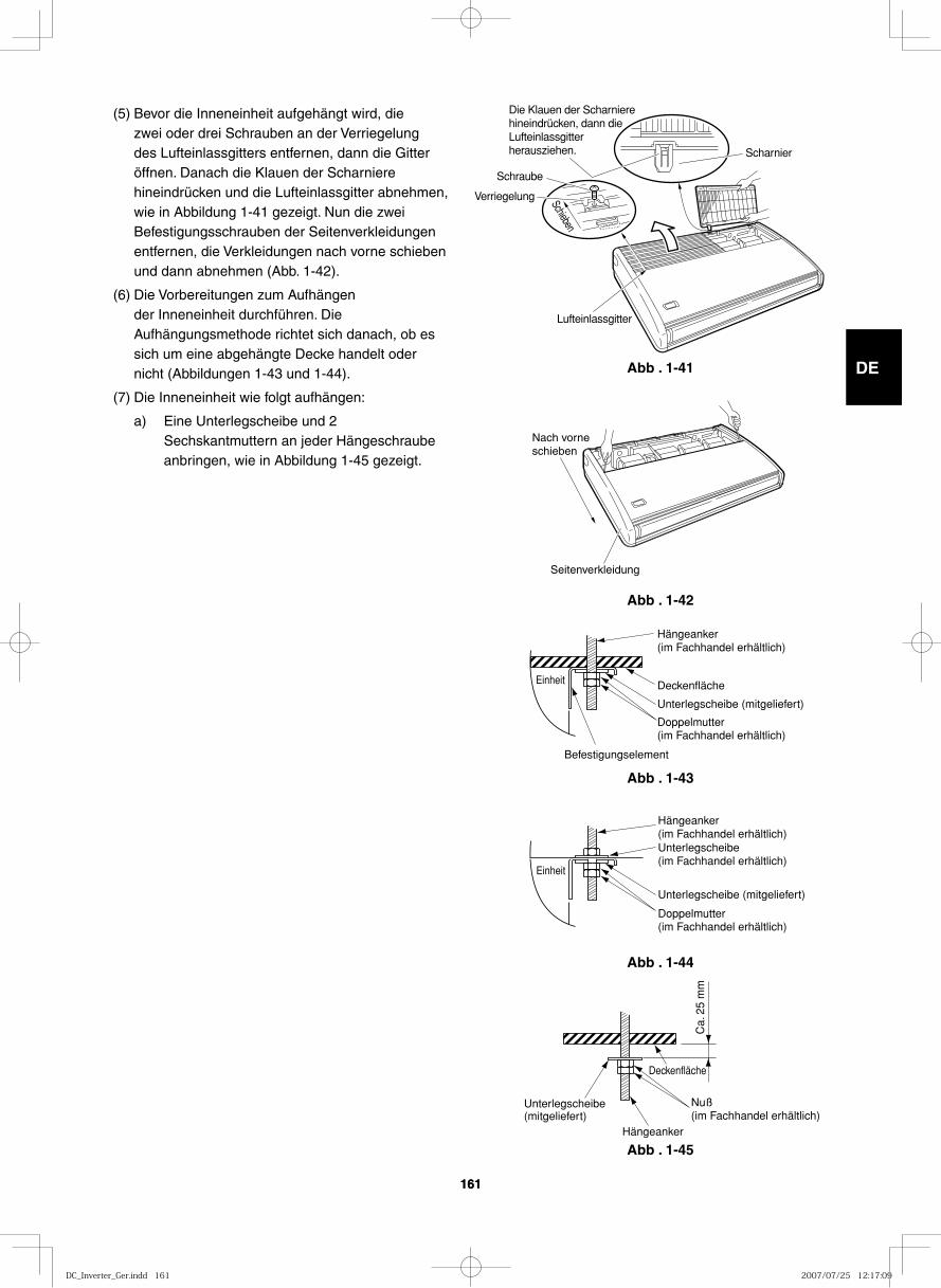
GB
FR
DE
IT
PT
GR
ES
161161
Abb . 1-41Schieben
Scharnier
Lufteinlassgitter
Die Klauen der Scharniere hineindrücken, dann die Lufteinlassgitter herausziehen.
Schraube
Verriegelung
Abb . 1-42
Nach vorne schieben
Seitenverkleidung
Abb . 1-43
Einheit
Hängeanker (im Fachhandel erhältlich)
Deckenfläche
Unterlegscheibe (mitgeliefert)
Doppelmutter(im Fachhandel erhältlich)
Befestigungselement
Abb . 1-44
Einheit
Hängeanker(im Fachhandel erhältlich)
Unterlegscheibe (mitgeliefert)
Unterlegscheibe (im Fachhandel erhältlich)
Doppelmutter(im Fachhandel erhältlich)
Abb . 1-45
Deckenfläche
Ca.
25
mm
Hängeanker
Unterlegscheibe (mitgeliefert)
Nuß(im Fachhandel erhältlich)
(5) Bevor die Inneneinheit aufgehängt wird, die zwei oder drei Schrauben an der Verriegelung des Lufteinlassgitters entfernen, dann die Gitter öffnen. Danach die Klauen der Scharniere hineindrücken und die Lufteinlassgitter abnehmen, wie in Abbildung 1-41 gezeigt. Nun die zwei Befestigungsschrauben der Seitenverkleidungen entfernen, die Verkleidungen nach vorne schieben und dann abnehmen (Abb. 1-42).
(6) Die Vorbereitungen zum Aufhängen der Inneneinheit durchführen. Die Aufhängungsmethode richtet sich danach, ob es sich um eine abgehängte Decke handelt oder nicht (Abbildungen 1-43 und 1-44).
(7) Die Inneneinheit wie folgt aufhängen:
a) Eine Unterlegscheibe und 2 Sechskantmuttern an jeder Hängeschraube anbringen, wie in Abbildung 1-45 gezeigt.
DC_Inverter_Ger.indd 161DC_Inverter_Ger.indd 161 2007/07/25 12:17:092007/07/25 12:17:09
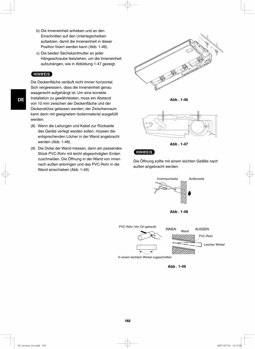
GB
FR
DE
IT
PT
GR
ES
162162
Abb . 1-46
Abb . 1-47
Abb . 1-48
Innenraumseite Außenseite
Abb . 1-49
In einem leichtem Winkel zugeschnitten
PVC-Rohr (Vor Ort gekauft)INNEN
Wand
Leichter Winkel
PVC-Rohr
AUSSEN
b) Die Inneneinheit anheben und an den Einschnitten auf den Unterlegscheiben aufsetzen, damit die Inneneinheit in dieser Position fixiert werden kann (Abb. 1-46).
c) Die beiden Sechskantmutter an jeder Hängeschraube festziehen, um die Inneneinheit aufzuhängen, wie in Abbildung 1-47 gezeigt.
HINWEIS
Die Deckenfläche verläuft nicht immer horizontal. Sich vergewissern, dass die Inneneinheit genau waagerecht aufgehängt ist. Um eine korrekte Installation zu gewährleisten, muss ein Abstand von 10 mm zwischen der Deckenfläche und der Deckenstütze gelassen werden; der Zwischenraum kann dann mit geeignetem Isoliermaterial ausgefüllt werden.
(8) Wenn die Leitungen und Kabel zur Rückseite des Geräts verlegt werden sollen, müssen die entsprechenden Löcher in der Wand angebracht werden (Abb. 1-48).
(9) Die Dicke der Wand messen, dann ein passendes Stück PVC-Rohr mit leicht abgeschrägten Enden zuschneiden. Die Öffnung in der Wand von innen nach außen anbringen und das PVC-Rohr in die Wand einschieben (Abb. 1-49).
HINWEIS
Die Öffnung sollte mit einem leichten Gefälle nach außen angebracht werden.
DC_Inverter_Ger.indd 162DC_Inverter_Ger.indd 162 2007/07/25 12:17:092007/07/25 12:17:09
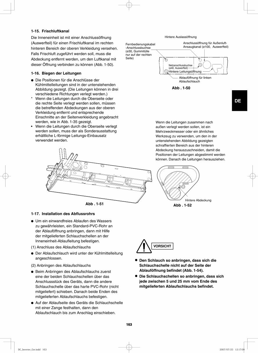
GB
FR
DE
IT
PT
GR
ES
163163
1-15. Frischluftkanal
Die Inneneinheit ist mit einer Anschlussöffnung (Auswerfteil) für einen Frischluftkanal im rechten hinteren Bereich der oberen Verkleidung versehen. Falls Frischluft zugeführt werden soll, muss die Abdeckung entfernt werden, um den Luftkanal mit dieser Öffnung verbinden zu können (Abb. 1-50).
1-16. Biegen der Leitungen
● Die Positionen für die Anschlüsse der Kühlmittelleitungen sind in der untenstehenden Abbildung gezeigt. (Die Leitungen können in drei verschiedene Richtungen verlegt werden.)
* Wenn die Leitungen durch die Oberseite oder die rechte Seite verlegt werden sollen, müssen die betreffenden Abdeckungen aus der oberen Verkleidung entfernt und entsprechende Einschnitte an der Seitenverkleidung angebracht werden, wie in Abb. 1-35 gezeigt.
• Wenn die Leitungen durch die Oberseite verlegt werden sollen, muss der als Sonderausstattung erhältliche L-förmige Leitungs-Einbausatz verwendet werden.
1-17. Installation des Abflussrohrs
● Um ein einwandfreies Ablaufen des Wassers zu gewährleisten, ein Standard-PVC-Rohr an der Ablauföffnung anbringen, dann mit Hilfe der mitgelieferten Schlauchschellen an der Inneneinheit-Ablaufleitung befestigen.
(1) Anschluss des Ablaufschlauchs
● Der Ablaufschlauch wird unter der Kühlmittelleitung angeschlossen.
(2) Anbringen des Ablaufschlauchs
● Beim Anbringen des Ablaufschlauchs zuerst eine der beiden Schlauchschellen über das Anschlussstück des Geräts, dann die andere Schlauchschelle über das harte PVC-Rohr (nicht mitgeliefert) schieben. Danach beide Enden des mitgelieferten Ablaufschlauchs befestigen.
● Auf der Ablaufseite des Geräts die Schlauchschelle mit einer Zange festhalten, dann den Ablaufschlauch bis zum Anschlag einschieben.
Hintere Auslassöffnung
Fernbedienungskabel-Anschlussbuchse (ø30, Gummitülle nur auf der rechten Seite)
Anschlussöffnung für Außenluft-Ansaugkanal (ø100, Auswerfteil)
Ablauföffnung für linken Ablaufschlauch
Netzanschlussbuchse(ø40, Auswerfteil)Hintere Leitungsöffnung
Abb . 1-50
Hintere Abdeckung
VORSICHT
● Den Schlauch so anbringen, dass sich die Schlauchschelle nicht auf der Seite der Ablauföffnung befindet (Abb. 1-54).
● Die Schlauchschellen so anbringen, dass sich jede zwischen 5 und 25 mm vom Ende des mitgelieferten Ablaufschlauchs befindet.
Wenn die Leitungen zusammen nach außen verlegt werden sollen, ist ein Mehrzweckmesser oder ein ähnliches Werkzeug zu verwenden, um den in der untenstehenden Abbildung gezeigten schraffierten Bereich aus der hinteren Abdeckung herauszuschneiden, damit die Positionen der Leitungen abgestimmt werden können. Danach die Leitungen herausziehen.
Abb . 1-51 Abb . 1-52
DC_Inverter_Ger.indd 163DC_Inverter_Ger.indd 163 2007/07/25 12:17:092007/07/25 12:17:09
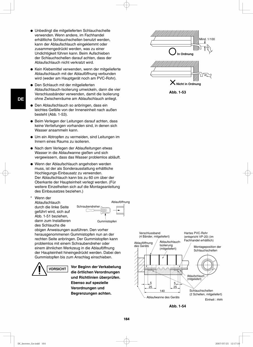
GB
FR
DE
IT
PT
GR
ES
164164
14025 25
55
Montageposition der Schlauchschellen
Ablaufschlauch (mitgeliefert)
Schlauchschellen(2 Schellen, mitgeliefert)
Ablaufwanne des Geräts
Ablauföffnung des Geräts
Ablaufschlauch-Isolierung (mitgeliefert)
Verschlussband(4 Bänder, mitgeliefert)
Hartes PVC-Rohr (entspricht VP-20) (im Fachhandel erhältlich)
Abb. 1-54
In Ordnung
Mind. 1/100
Nicht in Ordnung
Abb. 1-53
● Unbedingt die mitgelieferten Schlauchschelle verwenden. Wenn andere, im Fachhandel erhältliche Schlauchschellen benutzt werden, kann der Ablaufschlauch eingeklemmt oder zusammengedrückt werden, was zu einer Undichtigkeit führen kann. Beim Aufschieben der Schlauchschellen darauf achten, dass der Ablaufschlauch nicht verkratzt wird.
● Kein Klebemittel verwenden, wenn der mitgelieferte Ablaufschlauch mit der Ablauföffnung verbunden wird (weder am Hauptgerät noch am PVC-Rohr).
● Den Schlauch mit der mitgelieferten Ablaufschlauch-Isolierung umwickeln, dann die vier Verschlussbänder verwenden, damit die Isolierung ohne Zwischenräume am Ablaufschlauch anliegt.
● Den Ablaufschlauch so anbringen, dass ein leichtes Gefälle von der Inneneinheit nach außen besteht (Abb. 1-53).
● Beim Verlegen der Leitungen darauf achten, dass keine Vertiefungen vorhanden sind, in denen sich Wasser ansammeln kann.
● Um ein Abtropfen zu vermeiden, sind Leitungen im Innern eines Raums zu isolieren.
● Nach dem Verlegen der Ablaufleitungen etwas Wasser in die Ablaufwanne gießen und sich vergewissern, dass das Wasser problemlos abläuft.
● Wenn der Ablaufschlauch angehoben werden muss, ist der als Sonderausstattung erhältliche Hochlegungs-Einbausatz zu verwenden.Der Ablaufschlauch kann bis zu 60 cm über der Oberkante der Haupteinheit verlegt werden. (Für weitere Einzelheiten sich auf die Montageanleitung des Einbausatzes beziehen.)
* Wenn der Ablaufschlauch durch die linke Seite geführt wird, sich auf Abb. 1-51 beziehen, dann zum Installieren des Schlauchs die obigen Anweisungen ausführen. Den vorher herausgenommenen Gummistopfen nun an der rechten Seite anbringen. Der Gummistopfen kann problemlos mit einem Schraubendreher oder einem ähnlichen Werkzeug in die Ablauföffnung der Haupteinheit hineingedrückt werden. Dabei den Gummistopfen bis zum Anschlag einschieben.
Schraubendreher
Gummistopfen
Ablauföffnung
VORSICHTVor Beginn der Verkabelung die örtlichen Verordnungen und Richtlinien überprüfen. Ebenso auf spezielle Verordnungen und Begrenzungen achten.
Einheit : mm
DC_Inverter_Ger.indd 164DC_Inverter_Ger.indd 164 2007/07/25 12:17:102007/07/25 12:17:10
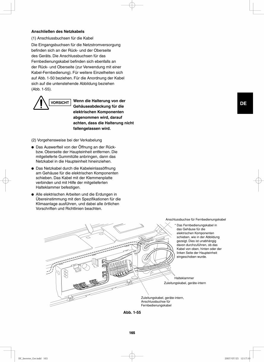
GB
FR
DE
IT
PT
GR
ES
165165
* Das Fernbedienungskabel in das Gehäuse für die elektrischen Komponenten schieben, wie in der Abbildung gezeigt. Dies ist unabhängig davon durchzuführen, ob das Kabel von oben, hinten oder der linken Seite der Haupteinheit eingeschoben wurde.
Anschlussbuchse für Fernbedienungskabel
Zuleitungskabel, geräte-intern
Zuleitungskabel, geräte-intern, Anschlussbuchse für Fernbedienungskabel
Halteklammer
Anschließen des Netzkabels
(1) Anschlussbuchsen für die Kabel
Die Eingangsbuchsen für die Netzstromversorgung befinden sich an der Rück- und der Oberseite des Geräts. Die Anschlussbuchsen für das Fernbedienungskabel befinden sich ebenfalls an der Rück- und Oberseite (zur Verwendung mit einer Kabel-Fernbedienung). Für weitere Einzelheiten sich auf Abb. 1-50 beziehen. Für die Anordnung der Kabel sich auf die untenstehende Abbildung beziehen (Abb. 1-55).
(2) Vorgehensweise bei der Verkabelung
● Das Auswerfteil von der Öffnung an der Rück- bzw. Oberseite der Haupteinheit entfernen. Die mitgelieferte Gummitülle anbringen, dann das Netzkabel in die Haupteinheit hineinziehen.
● Das Netzkabel durch die Kabeleinlassöffnung am Gehäuse für die elektrischen Komponenten schieben. Das Kabel mit der Klemmenplatte verbinden und mit Hilfe der mitgelieferten Halteklammer befestigen.
● Alle elektrischen Arbeiten und die Erdungen in Übereinstimmung mit den Spezifikationen für die Klimaanlage ausführen, und dabei alle örtlichen Vorschriften und Richtlinien beachten.
VORSICHT Wenn die Halterung von der Gehäuseabdeckung für die elektrischen Komponenten abgenommen wird, darauf achten, dass die Halterung nicht fallengelassen wird.
Abb. 1-55
DC_Inverter_Ger.indd 165DC_Inverter_Ger.indd 165 2007/07/25 12:17:102007/07/25 12:17:10
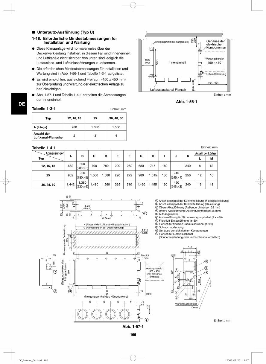
GB
FR
DE
IT
PT
GR
ES
166166
Abb. 1-56-1
Abb. 1-57-1
Inneneinheit Wartungsbereich
450 × 450
Luftauslasskanal-Flansch
min.250
min
. 400
min. 650
580
A (Neigungswinkel des Hängeankers) Gehäuse der elektrischen Komponenten
Kühlmittelleitung
min
. 25
0
■ Unterputz-Ausführung (Typ U)
1-18. Erforderliche Mindestabmessungen für Installation und Wartung
● Diese Klimaanlage wird normalerweise über der Deckenverkleidung installiert; in diesem Fall sind Inneneinheit und Luftkanäle nicht sichtbar. Von unten sind lediglich die Luftauslass- und Lufteinlassöffnungen zu erkennen.
● Die erforderlichen Mindestabmessungen für Installation und Wartung sind in Abb. 1-56-1 und Tabelle 1-3-1 aufgelistet.
● Es wird empfohlen, ausreichend Freiraum (450 x 450 mm) zur Überprüfung und Wartung der elektrischen Anlage zu berücksichtigen.
● Abb. 1-57-1 und Tabelle 1-4-1 enthalten die Abmessungen der Inneneinheit.
Tabelle 1-3-1
Tabelle 1-4-1
Typ
A (Länge)
Anzahl der Luftkanal-Flansche
36, 48, 60
1.560
4
25
1.080
3
12, 16, 18
780
2
Abmessungen Typ
12, 16, 18
25
36, 48, 60
E F G I J K
662 600
700 780 290 262 680 715 180 – 340 8 1 2 (200 × 3)
962 900
1.000 1.080 290 272 980 1.015 130 245
250 12 16 (180 × 5) (245 × 1)
1.4421.380
1.480 1.560 335 310 1.460 1.495 130 490
240 16 18 (230 × 6) (245 × 2)
Anzahl der Löcher
L M C D B A H
Anschlussnippel der Kühlmittelleitung (Flüssigkeitsleitung) Anschlussnippel der Kühlmittelleitung (Gasleitung)Obere Ablauföffnung (Außendurchmesser: 32 mm)Untere Ablauföffnung (Außendurchmesser: 26 mm)AufhängelascheAuslassöffnung für Stromversorgungskabel (2 x ø30)Frischluft-Einlassöffnung (ø150)Flansch für flexiblen Luftauslasskanal (ø200)SchlauchabdeckungGehäuse der elektrischen KomponentenFlansch für Lufteinlasskanal(Sonderausstattung oder im Fachhandel erhältlich)
9
10
9
10
11
11
(Neigungswinkel des Hängeankers)
(Nei
gung
swin
kel d
esH
änge
anke
rs)
M-ø3,3(Loch)
4-ø12(Loch)
(Loch)
A (O.D.)
L-ø6
I
10 10
105555
200
10 IJJ K
B
CD (150)
40
E E E F 7565
285
70 130
25 210
310
25175
35
903131
H (Abstand der Luftkanal-Hängeschrauben)G (Abmessungen der Deckenöffnung)
25
100
185
580
25
115
190
85
2570
30 160
630
25 10
8827
5Ab
mes
sung
en d
er D
ecke
nöffn
ung
260
(O.D
.)
1919
Wartungsbereich(450 × 450)
(im Fachhandelerhältlich)
Wartungsabdeckung
Decke
Einheit : mm
Einheit: mm
Einheit: mm
Einheit : mm
DC_Inverter_Ger.indd 166DC_Inverter_Ger.indd 166 2007/07/25 12:17:102007/07/25 12:17:10
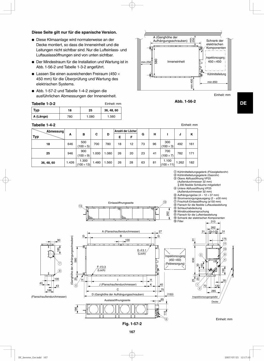
GB
FR
DE
IT
PT
GR
ES
167
Abb. 1-56-2
min.250 580
min
.400
A (Ganghöhe der Aufhängungsschrauben) m
in.
250
Inneneinheit
min.650
Schrank der elektrischen Komponenten
Inspektionszugang450 450
Kühlmittelleitung
Diese Seite gilt nur für die spanische Version.
● Diese Klimaanlage wird normalerweise an der Decke montiert, so dass die Inneneinheit und die Leitungen nicht sichtbar sind. Nur die Lufteinlass- und Luftauslassöffnungen sind von unten sichtbar.
● Der Mindestraum für die Installation und Wartung ist in Abb. 1-56-2 und Tabelle 1-3-2 angeführt.
● Lassen Sie einen ausreichenden Freiraum (450 × 450 mm) für die Überprüfung und Wartung des elektrischen Systems.
● Abb. 1-57-2 und Tabelle 1-4-2 zeigen die ausführlichen Abmessungen der Inneneinheit.
Typ
A (Länge)
36, 48, 60
1.560
25
1.080
18
780
Abmessung
Typ
18
25
36, 48, 60
E F G H I J K
646 500
700 780 18 12 73 96 492 (100 × 5)
946 900
1.000 1.080 26 20 23 41 782 (100 × 9)
1.4261.300
1.480 1.560 26 28 63 81 1.262
161
171
182 (100 × 13)
300 (100 × 3)
700 (100 × 7)
1.100(100 × 11)
C D B A Anzahl der Löcher
262
100
580
25
H H I
(Gan
ghöh
e de
r A
ufhä
ngun
gssc
hrau
ben)
A (Flanschaußendurchmesser)
Einlassöffnungsseite
(Flanschaußendurchmesser)Auslassöffnungsseite
J (Flanschaußendurchmesser)
27
B G G
K 40
C
D (Ganghöhe der Aufhängungsschrauben)
75
(150)
115 18
6
65
90
100
43 43
185
186
310
262
31 100p×2=200 31
35
70 130
175
630
31
25
190
285
160
25
30
Inspektionszugang(450 450)
(Feldversorgung)
E- 3.1(Loch)
F- 3.3(Loch)
Inspektionszugangstafel
Decke
1
2
3
4
9
10
11
6
5
7
8
12
13
Einheit: mm
Einheit: mm
Einheit: mm
Einheit: mm
Kühlmittelleitungsgelenk (Flüssigkeitsrohr)Kühlmittelleitungsgelenk (Gasrohr)Obere Abflussöffnung VP25(Außendurchmesser 32 mm) 200 flexible Schläuche mitgeliefertUntere Abflussöffnung VP25(Außendurchmesser 32 mm)Aufhängungsöse (4 – 12 × 37 mm)Stromversorgungsausgang (2 – ø30 mm)Frischluft-Einlassöffnung (ø150 mm)Flansch für die flexible LuftauslassleitungSchlauchabdeckung
Flansch für die LufteinlassleitungSchrank der elektrischen Komponenten
11Winddruckbeanspruchung10
12
Filter13
Fig. 1-57-2
Tabelle 1-4-2
Tabelle 1-3-2
DC_Inverter_Ger.indd 167DC_Inverter_Ger.indd 167 2007/07/25 12:17:102007/07/25 12:17:10
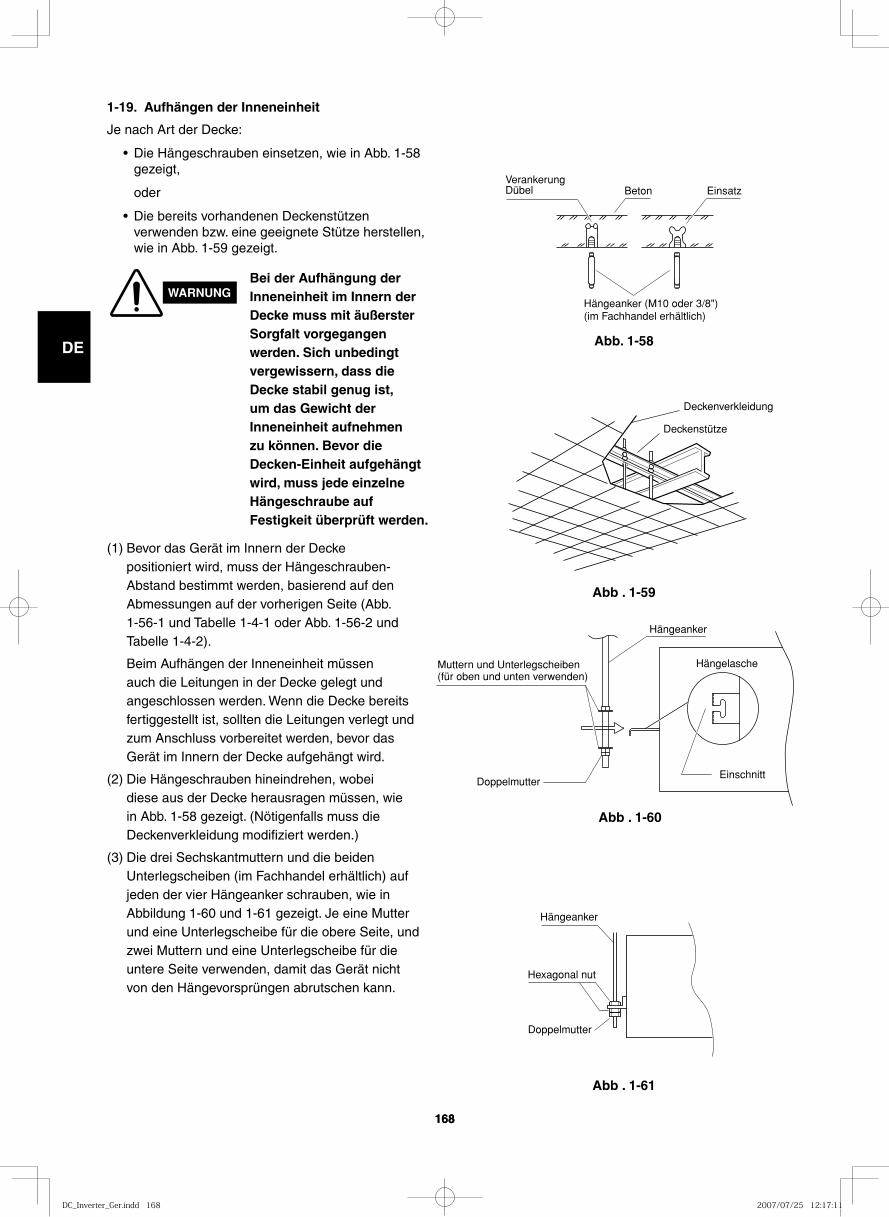
GB
FR
DE
IT
PT
GR
ES
168168
Abb. 1-58
1-19. Aufhängen der Inneneinheit
Je nach Art der Decke:
• Die Hängeschrauben einsetzen, wie in Abb. 1-58 gezeigt,
oder
• Die bereits vorhandenen Deckenstützen verwenden bzw. eine geeignete Stütze herstellen, wie in Abb. 1-59 gezeigt.
VerankerungDübel Beton Einsatz
Hängeanker (M10 oder 3/8")(im Fachhandel erhältlich)
Abb . 1-59
Abb . 1-60
Abb . 1-61
Deckenverkleidung
Deckenstütze
Hängeanker
Hängelasche
DoppelmutterEinschnitt
Muttern und Unterlegscheiben (für oben und unten verwenden)
Hängeanker
Hexagonal nut
Doppelmutter
WARNUNGBei der Aufhängung der Inneneinheit im Innern der Decke muss mit äußerster Sorgfalt vorgegangen werden. Sich unbedingt vergewissern, dass die Decke stabil genug ist, um das Gewicht der Inneneinheit aufnehmen zu können. Bevor die Decken-Einheit aufgehängt wird, muss jede einzelne Hängeschraube auf Festigkeit überprüft werden.
(1) Bevor das Gerät im Innern der Decke positioniert wird, muss der Hängeschrauben-Abstand bestimmt werden, basierend auf den Abmessungen auf der vorherigen Seite (Abb. 1-56-1 und Tabelle 1-4-1 oder Abb. 1-56-2 und Tabelle 1-4-2).
Beim Aufhängen der Inneneinheit müssen auch die Leitungen in der Decke gelegt und angeschlossen werden. Wenn die Decke bereits fertiggestellt ist, sollten die Leitungen verlegt und zum Anschluss vorbereitet werden, bevor das Gerät im Innern der Decke aufgehängt wird.
(2) Die Hängeschrauben hineindrehen, wobei diese aus der Decke herausragen müssen, wie in Abb. 1-58 gezeigt. (Nötigenfalls muss die Deckenverkleidung modifiziert werden.)
(3) Die drei Sechskantmuttern und die beiden Unterlegscheiben (im Fachhandel erhältlich) auf jeden der vier Hängeanker schrauben, wie in Abbildung 1-60 und 1-61 gezeigt. Je eine Mutter und eine Unterlegscheibe für die obere Seite, und zwei Muttern und eine Unterlegscheibe für die untere Seite verwenden, damit das Gerät nicht von den Hängevorsprüngen abrutschen kann.
DC_Inverter_Ger.indd 168DC_Inverter_Ger.indd 168 2007/07/25 12:17:112007/07/25 12:17:11
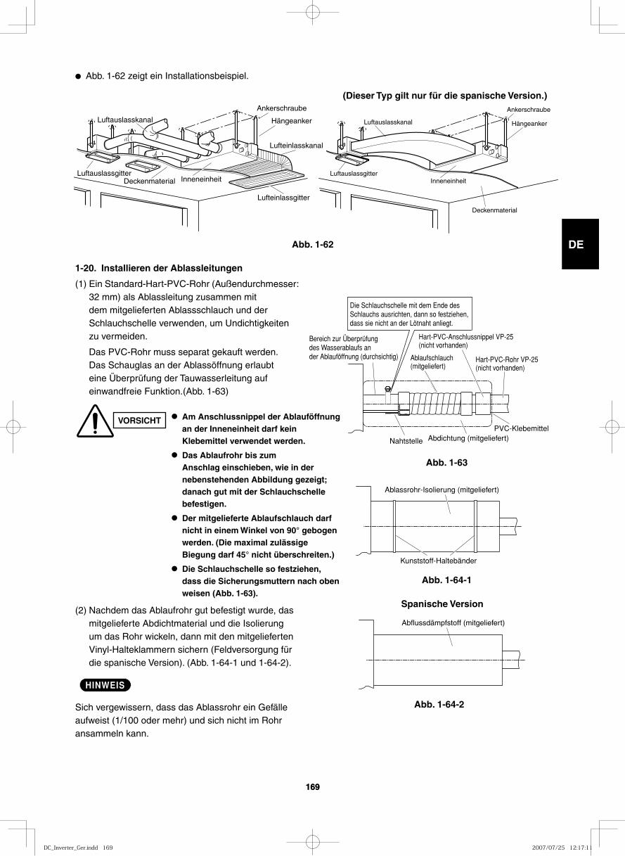
GB
FR
DE
IT
PT
GR
ES
169169
● Abb. 1-62 zeigt ein Installationsbeispiel.
Luftauslasskanal
LuftauslassgitterDeckenmaterial Inneneinheit
Ankerschraube
Hängeanker
Lufteinlasskanal
Lufteinlassgitter
Luftauslasskanal
Luftauslassgitter
Deckenmaterial
Inneneinheit
Ankerschraube
Hängeanker
(Dieser Typ gilt nur für die spanische Version.)
Abb. 1-62
Abb. 1-63
Abb. 1-64-1
Ablaufschlauch (mitgeliefert)
Abdichtung (mitgeliefert)
Die Schlauchschelle mit dem Ende des Schlauchs ausrichten, dann so festziehen, dass sie nicht an der Lötnaht anliegt.
Bereich zur Überprüfung des Wasserablaufs an der Ablauföffnung (durchsichtig) Hart-PVC-Rohr VP-25
(nicht vorhanden)
PVC-Klebemittel
Nahtstelle
Hart-PVC-Anschlussnippel VP-25 (nicht vorhanden)
Kunststoff-Haltebänder
Ablassrohr-Isolierung (mitgeliefert)
1-20. Installieren der Ablassleitungen
(1) Ein Standard-Hart-PVC-Rohr (Außendurchmesser: 32 mm) als Ablassleitung zusammen mit dem mitgelieferten Ablassschlauch und der Schlauchschelle verwenden, um Undichtigkeiten zu vermeiden.
Das PVC-Rohr muss separat gekauft werden. Das Schauglas an der Ablassöffnung erlaubt eine Überprüfung der Tauwasserleitung auf einwandfreie Funktion.(Abb. 1-63)
VORSICHT ● Am Anschlussnippel der Ablauföffnung an der Inneneinheit darf kein Klebemittel verwendet werden.
● Das Ablaufrohr bis zum Anschlag einschieben, wie in der nebenstehenden Abbildung gezeigt; danach gut mit der Schlauchschelle befestigen.
● Der mitgelieferte Ablaufschlauch darf nicht in einem Winkel von 90° gebogen werden. (Die maximal zulässige Biegung darf 45° nicht überschreiten.)
● Die Schlauchschelle so festziehen, dass die Sicherungsmuttern nach oben weisen (Abb. 1-63).
(2) Nachdem das Ablaufrohr gut befestigt wurde, das mitgelieferte Abdichtmaterial und die Isolierung um das Rohr wickeln, dann mit den mitgelieferten Vinyl-Halteklammern sichern (Feldversorgung für die spanische Version). (Abb. 1-64-1 und 1-64-2).
HINWEIS
Sich vergewissern, dass das Ablassrohr ein Gefälle aufweist (1/100 oder mehr) und sich nicht im Rohr ansammeln kann.
Abb. 1-64-2
Abflussdämpfstoff (mitgeliefert)
Spanische Version
DC_Inverter_Ger.indd 169DC_Inverter_Ger.indd 169 2007/07/25 12:17:112007/07/25 12:17:11
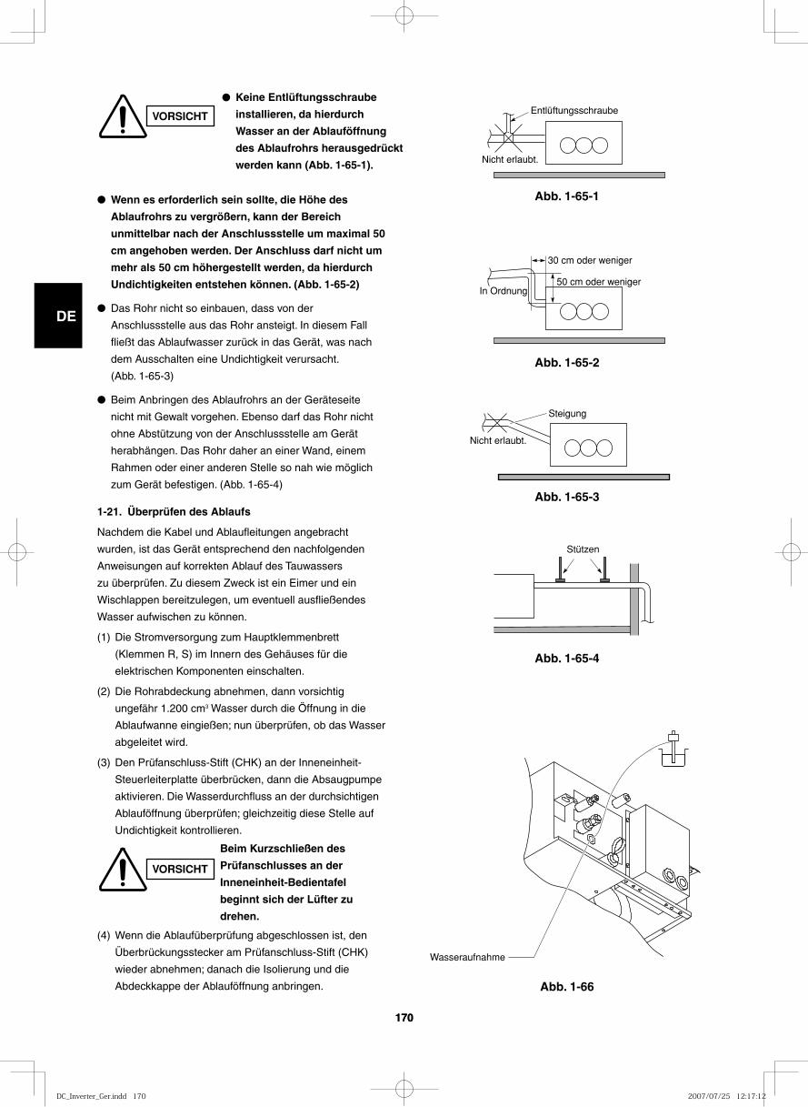
GB
FR
DE
IT
PT
GR
ES
170170
Abb. 1-65-1
Abb. 1-65-2
Abb. 1-65-3
Abb. 1-65-4
Abb. 1-66
Entlüftungsschraube
Nicht erlaubt.
In Ordnung
30 cm oder weniger
50 cm oder weniger
Nicht erlaubt.
Steigung
Stützen
Wasseraufnahme
● Wenn es erforderlich sein sollte, die Höhe des
Ablaufrohrs zu vergrößern, kann der Bereich
unmittelbar nach der Anschlussstelle um maximal 50
cm angehoben werden. Der Anschluss darf nicht um
mehr als 50 cm höhergestellt werden, da hierdurch
Undichtigkeiten entstehen können. (Abb. 1-65-2)
● Das Rohr nicht so einbauen, dass von der
Anschlussstelle aus das Rohr ansteigt. In diesem Fall
fließt das Ablaufwasser zurück in das Gerät, was nach
dem Ausschalten eine Undichtigkeit verursacht.
(Abb. 1-65-3)
● Beim Anbringen des Ablaufrohrs an der Geräteseite
nicht mit Gewalt vorgehen. Ebenso darf das Rohr nicht
ohne Abstützung von der Anschlussstelle am Gerät
herabhängen. Das Rohr daher an einer Wand, einem
Rahmen oder einer anderen Stelle so nah wie möglich
zum Gerät befestigen. (Abb. 1-65-4)
1-21. Überprüfen des Ablaufs
Nachdem die Kabel und Ablaufleitungen angebracht
wurden, ist das Gerät entsprechend den nachfolgenden
Anweisungen auf korrekten Ablauf des Tauwassers
zu überprüfen. Zu diesem Zweck ist ein Eimer und ein
Wischlappen bereitzulegen, um eventuell ausfließendes
Wasser aufwischen zu können.
(1) Die Stromversorgung zum Hauptklemmenbrett
(Klemmen R, S) im Innern des Gehäuses für die
elektrischen Komponenten einschalten.
(2) Die Rohrabdeckung abnehmen, dann vorsichtig
ungefähr 1.200 cm3 Wasser durch die Öffnung in die
Ablaufwanne eingießen; nun überprüfen, ob das Wasser
abgeleitet wird.
(3) Den Prüfanschluss-Stift (CHK) an der Inneneinheit-
Steuerleiterplatte überbrücken, dann die Absaugpumpe
aktivieren. Die Wasserdurchfluss an der durchsichtigen
Ablauföffnung überprüfen; gleichzeitig diese Stelle auf
Undichtigkeit kontrollieren.
(4) Wenn die Ablaufüberprüfung abgeschlossen ist, den
Überbrückungsstecker am Prüfanschluss-Stift (CHK)
wieder abnehmen; danach die Isolierung und die
Abdeckkappe der Ablauföffnung anbringen.
VORSICHT
● Keine Entlüftungsschraube
installieren, da hierdurch
Wasser an der Ablauföffnung
des Ablaufrohrs herausgedrückt
werden kann (Abb. 1-65-1).
VORSICHT
Beim Kurzschließen des
Prüfanschlusses an der
Inneneinheit-Bedientafel
beginnt sich der Lüfter zu
drehen.
DC_Inverter_Ger.indd 170DC_Inverter_Ger.indd 170 2007/07/25 12:17:122007/07/25 12:17:12
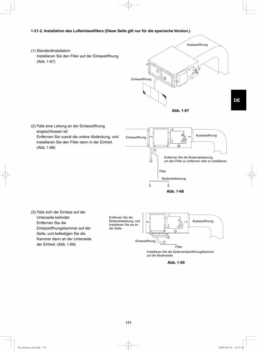
GB
FR
DE
IT
PT
GR
ES
171
(1) StandardinstallationInstallieren Sie den Filter auf der Einlassöffnung. (Abb. 1-67)
(2) Falls eine Leitung an der Einlassöffnung angeschlossen ist:Entfernen Sie zuerst die untere Abdeckung, und installieren Sie den Filter dann in der Einheit. (Abb. 1-68)
(3) Falls sich der Einlass auf der Unterseite befindet:Entfernen Sie die Einlassöffnungskammer auf der Seite, und befestigen Sie die Kammer dann an der Unterseite der Einheit. (Abb. 1-69)
Auslassöffnung
Einlassöffnung 2
1
AuslassöffnungEinlassöffnung
2
1
Entfernen Sie die Bodenabdeckung, um den Filter zu entfernen oder zu installieren.
Filter
Bodenabdeckung
Auslassöffnung
Einlassöffnung2
1
Installieren Sie die Seiteneinlassöffnungskammerauf der Bodenseite.
Filter
Entfernen Sie dieBodenabdeckung, undinstallieren Sie sie ander Seite.
Abb. 1-67
Abb. 1-68
Abb. 1-69
1-21-2. Installation des Lufteinlassfilters (Diese Seite gilt nur für die spanische Version.)
DC_Inverter_Ger.indd 171DC_Inverter_Ger.indd 171 2007/07/25 12:17:122007/07/25 12:17:12
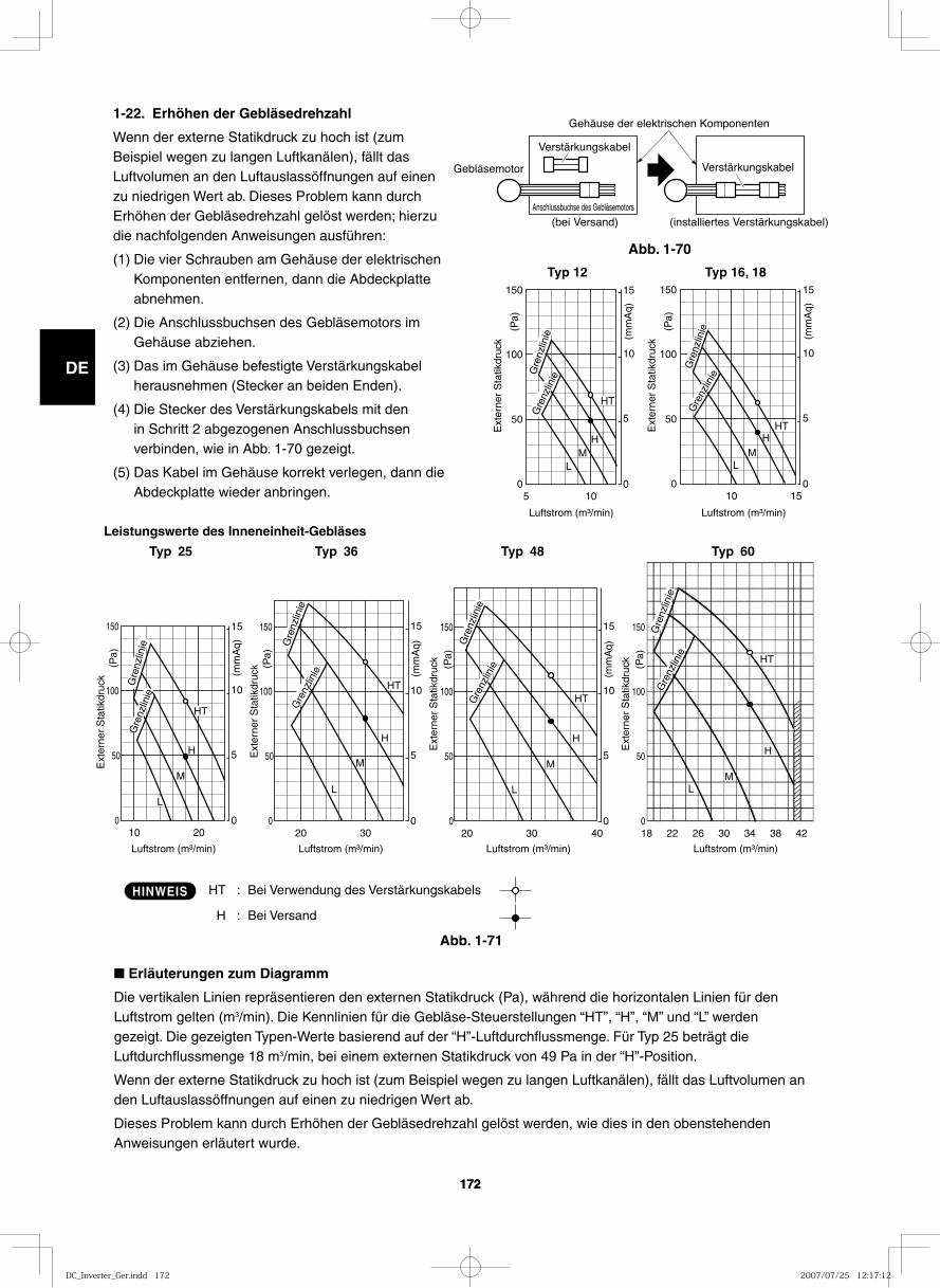
GB
FR
DE
IT
PT
GR
ES
172172
5 E
xter
ner
Sta
tikdr
uck
0
50
100
0
5
10
15 150
10
(mm
Aq)
(Pa)
HT
H M
L
20
Ext
erne
r S
tatik
druc
k
0
50
0
5
10
15 150
10
HT
H
L
100
M
(mm
Aq)
(Pa)
30 40 18 22 26 30 34 38 42
Ext
erne
r S
tatik
druc
k
0
50
0
5
10
15 150
20
L
100
M
H
M
H
L
(mm
Aq)
(Pa)
Ext
erne
r S
tatik
druc
k
0
50
150
100
(Pa)
HT
HT
30
Ext
erne
r S
tatik
druc
k
0
50
0
5
10
15 150
20
HT
L
100
M
H
(mm
Aq)
(Pa)
15
Ext
erne
r S
tatik
druc
k
0
50
0
5
10
15 150
10
HT
M L
100
H
(mm
Aq)
(Pa)
Typ 16, 18Typ 12
Leistungswerte des Inneneinheit-Gebläses
Typ 25 Typ 36 Typ 48 Typ 60
Luftstrom (m³/min) Luftstrom (m³/min) Luftstrom (m³/min) Luftstrom (m³/min)
Luftstrom (m³/min)Luftstrom (m³/min)
Gre
nzlin
ie
Gre
nzlin
ie Gre
nzlin
ieG
renz
linie
Gre
nzlin
ie
Gre
nzlin
ie
Gre
nzlin
ieG
renz
linie
Gre
nzlin
ie
Gre
nzlin
ie
Gre
nzlin
ie
Gre
nzlin
ie
HT : Bei Verwendung des Verstärkungskabels
H : Bei Versand
HINWEIS
1-22. Erhöhen der Gebläsedrehzahl
Wenn der externe Statikdruck zu hoch ist (zum Beispiel wegen zu langen Luftkanälen), fällt das Luftvolumen an den Luftauslassöffnungen auf einen zu niedrigen Wert ab. Dieses Problem kann durch Erhöhen der Gebläsedrehzahl gelöst werden; hierzu die nachfolgenden Anweisungen ausführen:
(1) Die vier Schrauben am Gehäuse der elektrischen Komponenten entfernen, dann die Abdeckplatte abnehmen.
(2) Die Anschlussbuchsen des Gebläsemotors im Gehäuse abziehen.
(3) Das im Gehäuse befestigte Verstärkungskabel herausnehmen (Stecker an beiden Enden).
(4) Die Stecker des Verstärkungskabels mit den in Schritt 2 abgezogenen Anschlussbuchsen verbinden, wie in Abb. 1-70 gezeigt.
(5) Das Kabel im Gehäuse korrekt verlegen, dann die Abdeckplatte wieder anbringen.
Abb. 1-70
Abb. 1-71
Verstärkungskabel
Gehäuse der elektrischen Komponenten
(bei Versand) (installiertes Verstärkungskabel)Anschlussbuchse des Gebläsemotors
Gebläsemotor Verstärkungskabel
■ Erläuterungen zum Diagramm
Die vertikalen Linien repräsentieren den externen Statikdruck (Pa), während die horizontalen Linien für den Luftstrom gelten (m3/min). Die Kennlinien für die Gebläse-Steuerstellungen “HT”, “H”, “M” und “L” werden gezeigt. Die gezeigten Typen-Werte basierend auf der “H”-Luftdurchflussmenge. Für Typ 25 beträgt die Luftdurchflussmenge 18 m3/min, bei einem externen Statikdruck von 49 Pa in der “H”-Position.
Wenn der externe Statikdruck zu hoch ist (zum Beispiel wegen zu langen Luftkanälen), fällt das Luftvolumen an den Luftauslassöffnungen auf einen zu niedrigen Wert ab.
Dieses Problem kann durch Erhöhen der Gebläsedrehzahl gelöst werden, wie dies in den obenstehenden Anweisungen erläutert wurde.
DC_Inverter_Ger.indd 172DC_Inverter_Ger.indd 172 2007/07/25 12:17:122007/07/25 12:17:12
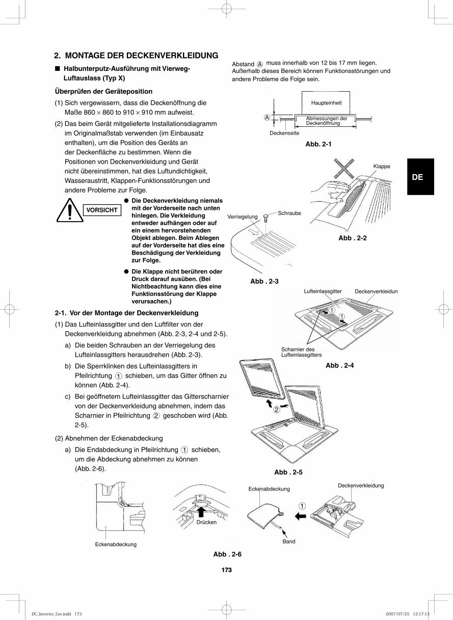
GB
FR
DE
IT
PT
GR
ES
173173
■ Halbunterputz-Ausführung mit Vierweg-Luftauslass (Typ X)
Überprüfen der Geräteposition
(1) Sich vergewissern, dass die Deckenöffnung die Maße 860 × 860 to 910 × 910 mm aufweist.
(2) Das beim Gerät mitgelieferte Installationsdiagramm im Originalmaßstab verwenden (im Einbausatz enthalten), um die Position des Geräts an der Deckenfläche zu bestimmen. Wenn die Positionen von Deckenverkleidung und Gerät nicht übereinstimmen, hat dies Luftundichtigkeit, Wasseraustritt, Klappen-Funktionsstörungen und andere Probleme zur Folge.
VORSICHT
● Die Deckenverkleidung niemals mit der Vorderseite nach unten hinlegen. Die Verkleidung entweder aufhängen oder auf ein einem hervorstehenden Objekt ablegen. Beim Ablegen auf der Vorderseite hat dies eine Beschädigung der Verkleidung zur Folge.
● Die Klappe nicht berühren oder Druck darauf ausüben. (Bei Nichtbeachtung kann dies eine Funktionsstörung der Klappe verursachen.)
Abstand A muss innerhalb von 12 bis 17 mm liegen.Außerhalb dieses Bereich können Funktionsstörungen und andere Probleme die Folge sein.
Deckenseite
Haupteinheit
Abmessungen der Deckenöffnung
A
Abb. 2-1
Klappe
Abb . 2-2
Abb . 2-3
2
Abb . 2-5
2-1. Vor der Montage der Deckenverkleidung
(1) Das Lufteinlassgitter und den Luftfilter von der Deckenverkleidung abnehmen (Abb. 2-3, 2-4 und 2-5).
a) Die beiden Schrauben an der Verriegelung des Lufteinlassgitters herausdrehen (Abb. 2-3).
b) Die Sperrklinken des Lufteinlassgitters in Pfeilrichtung 1 schieben, um das Gitter öffnen zu können (Abb. 2-4).
c) Bei geöffnetem Lufteinlassgitter das Gitterscharnier von der Deckenverkleidung abnehmen, indem das Scharnier in Pfeilrichtung 2 geschoben wird (Abb. 2-5).
(2) Abnehmen der Eckenabdeckung
a) Die Endabdeckung in Pfeilrichtung 1 schieben, um die Abdeckung abnehmen zu können (Abb. 2-6).
Eckenabdeckung
Deckenverkleidung
Band
Drücken
1
Eckenabdeckung
Abb . 2-6
Lufteinlassgitter Deckenverkleidun
Scharnier des Lufteinlassgitters
11
Abb . 2-4
VerriegelungSchraube
2. MONTAGE DER DECKENVERKLEIDUNG
DC_Inverter_Ger.indd 173DC_Inverter_Ger.indd 173 2007/07/25 12:17:132007/07/25 12:17:13
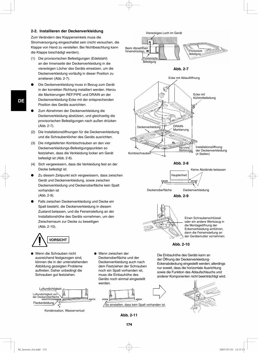
GB
FR
DE
IT
PT
GR
ES
174174
VORSICHT
2-2. Installieren der Deckenverkleidung
Zum Verändern des Klappenwinkels muss die Stromversorgung eingeschaltet sein (nicht versuchen, die Klappe von Hand zu verstellen. Bei Nichtbeachtung kann
die Klappe beschädigt werden).
(1) Die provisorischen Befestigungen (Edelstahl) an der Innenseite der Deckenverkleidung in die viereckigen Löcher des Geräts einsetzen, um die Deckenverkleidung vorläufig in dieser Position zu arretieren (Abb. 2-7).
● Die Deckenverkleidung muss in Bezug zum Gerät in der korrekten Richtung installiert werden. Hierzu die Markierungen REF.PIPE und DRAIN an der Deckenverkleidung-Ecke mit der entsprechenden Position des Geräts ausrichten.
● Zum Abnehmen der Deckenverkleidung die
Deckenverkleidung abstützen, und gleichzeitig die
provisorischen Befestigungen nach außen drücken
(Abb. 2-7).
(2) Die Installationsöffnungen für die Deckenverkleidung und die Schraubenlöcher des Geräts ausrichten.
(3) Die mitgelieferten Kombischrauben an den vier Deckenverkleidungs-Befestigungspunkten so festziehen, dass die Verkleidung locker am Gerät befestigt ist (Abb. 2-8).
(4) Sich vergewissern, dass die Verkleidung fest an der Decke befestigt ist.
● Zu diesem Zeitpunkt sich vergewissern, dass zwischen Gerät und Deckenverkleidung, sowie zwischen Deckenverkleidung und Deckenoberfläche kein Spalt vorhanden ist (Abb. 2-9).
● Falls zwischen Deckenverkleidung und Decke ein Spalt besteht, die Deckenverkleidung in diesem Zustand belassen, und die Feineinstellung an der Installationshöhe des Geräts vornehmen, um den Zwischenraum zur Decke zu beseitigen (Abb. 2-10).
Viereckiges Loch im Gerät
Provisorische Befestigung
Beim Abnehmen hineindrücken Provisorische
Befestigung
Abb. 2-7
Ecke mit Ablauföffnung
Ecke mit Kühlmittelleitung
Installationsöffnung der Deckenverkleidung (4 Stellen)
Deckenverkleidung
Kombischrauben
DRAIN-Markierung
REF.PIPE-Markierung
Abb. 2-8
Keine Abstände belassen
Deckenverkleidung
Haupteinheit
Deckenoberfläche
Abb. 2-9
Einen Schraubenschlüssel oder ein andere Werkzeug in die Montageöffnung der Eckenverkleidung einführen, dann die Feineinstellung an der Gerätemutter vornehmen.
Luftundichtigkeit
Luftundichtigkeit von der Deckenoberfläche
Fleckenbildung
Kondensation, Wasserverlust
So einstellen, dass kein Spalt vorhanden ist.
Abb. 2-10
Abb. 2-11
● Wenn die Schrauben nicht ausreichend festgezogen sind, können die in der untenstehenden Abbildung gezeigten Probleme auftreten. Daher unbedingt die Schrauben gut festziehen.
● Wenn zwischen der Deckenoberfläche und der Deckenverkleidung auch nach dem Festziehen der Schrauben noch ein Spalt vorhanden ist, muss die Einbauhöhe des Geräts noch einmal eingestellt werden.
Die Einbauhöhe des Geräts kann an der Öffnung der Deckenverkleidung-Eckenabdeckung eingestellt werden; allerdings nur soweit, dass die horizontale Ausrichtung sowie die Funktion des Ablaufschlauchs und anderer Komponenten nicht beeinträchtigt wird.
VORSICHT
DC_Inverter_Ger.indd 174DC_Inverter_Ger.indd 174 2007/07/25 12:17:132007/07/25 12:17:13
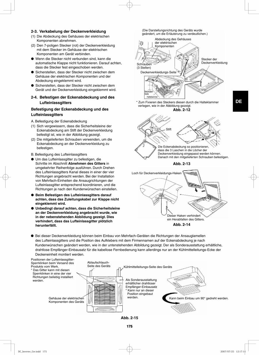
GB
FR
DE
IT
PT
GR
ES
175175
2-3. Verkabelung der Deckenverkleidung (1) Die Abdeckung des Gehäuses der elektrischen
Komponenten abnehmen.(2) Den 7-poligen Stecker (rot) der Deckenverkleidung
mit dem Stecker im Gehäuse der elektrischen Komponenten am Gerät verbinden.
● Wenn die Stecker nicht verbunden sind, kann die automatische Klappe nicht funktionieren. Darauf achten, dass die Stecker fest eingeschoben werden.
● Sicherstellen, dass der Stecker nicht zwischen dem Gehäuse der elektrischen Komponenten und der Abdeckung eingeklemmt wird.
● Sicherstellen, dass der Stecker nicht zwischen dem Gerät und der Deckenverkleidung eingeklemmt wird.
2-4. Befestigen der Eckenabdeckung und des Lufteinlassgitters
Befestigung der Eckenabdeckung und des Lufteinlassgitters
A. Befestigung der Eckenabdeckung (1) Sich vergewissern, dass die Sicherheitsleine der
Eckenabdeckung am Stift der Deckenverkleidung befestigt ist, wie in der Abbildung gezeigt.
(2) Die mitgelieferten Schrauben verwenden, um die Eckenabdeckung an der Deckenverkleidung zu befestigen.
B. Befestigung des Lufteinlassgitters● Um das Lufteinlassgitter zu befestigen, die
Schritte im Abschnitt Abnehmen des Gitters in umgekehrter Reihenfolge ausführen. Durch Drehen des Lufteinlassgitters Kanal dieses in einer der vier Richtungen angebracht werden. Bei der Installation von Mehrfach-Einheiten die Ansaugrichtungen der Lufteinlassgitter entsprechend koordinieren, und die Richtungen je nach den Kundenwünschen einstellen.
● Beim Befestigen des Lufteinlassgitters darauf achten, dass das Zuleitungskabel zur Klappe nicht eingeklemmt wird.
● Unbedingt darauf achten, dass die Sicherheitsleine an der Deckenverkleidung angebracht wurde, wie in der nebenstehenden Abbildung gezeigt. Dies verhindert, dass das Lufteinlassgitter plötzlich herunterfällt.
(Die Darstellungsrichtung des Geräts wurde geändert, um die Erläuterung zu verdeutlichen.)
Stecker der Deckenverkleidung
Deckenverkleidungs-Seite
Schrauben (3 Stellen)
Netzkabel-Seite
Halteklammer
Abdeckung des Gehäuses der elektrischen Komponenten
* Zum Fixieren des Steckers diesen durch die Halteklammer verlegen, wie in der Abbildung gezeigt.
Die Eckenabdeckung so positionieren, dass die 3 Laschen in die Löcher der Deckenverkleidung eingepasst werden können.Danach mit den mitgelieferten Schrauben befestigen.
Stift
● Bei dieser Deckenverkleidung können beim Einbau von Mehrfach-Geräten die Richtungen der Ansauglamellen des Lufteinlassgitters und die Position des Aufklebers mit dem Firmennamen auf der Eckenabdeckung je nach Kundenwünschen geändert werden, wie in der untenstehenden Abbildung gezeigt. Der als Sonderausstattung erhältliche, drahtlose Empfänger-Einbausatz für die kabellose Fernbedienung kann allerdings nur an der Kühlmittelleitungs-Ecke der Deckeneinheit montiert werden.
Gehäuse der elektrischen Komponenten des Geräts
Ablaufschlauch-Seite des Geräts Kühlmittelleitungs-Seite des Geräts
Als Sonderausstattung erhältlicher drahtloser Empfänger-Einbausatz * Kann nur an dieser Position eingebaut werden. Kann beim Einbau um 90° gedreht werden.
Positionen der Lufteinlassgitter-Sperrklinken beim Versand des Produkts vom Werk.* Das Gitter kann mit diesen Sperrklinken in eine der vier Richtungen beliebig installiert werden.
Abb. 2-12
Abb. 2-13
Loch für Deckenverkleidungs-Haken
Dieser Haken verhindert ein Herabfallen des Gitters.
Abb. 2-14
Abb. 2-15
DC_Inverter_Ger.indd 175DC_Inverter_Ger.indd 175 2007/07/25 12:17:142007/07/25 12:17:14
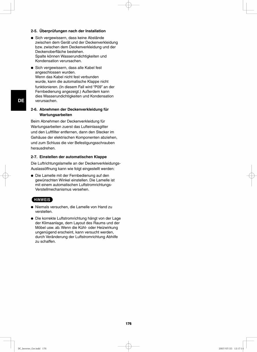
GB
FR
DE
IT
PT
GR
ES
176176
2-5. Überprüfungen nach der Installation
● Sich vergewissern, dass keine Abstände zwischen dem Gerät und der Deckenverkleidung bzw. zwischen dem Deckenverkleidung und der Deckenoberfläche bestehen.Spalte können Wasserundichtigkeiten und Kondensation verursachen.
● Sich vergewissern, dass alle Kabel fest angeschlossen wurden.Wenn das Kabel nicht fest verbunden wurde, kann die automatische Klappe nicht funktionieren. (In diesem Fall wird “P09” an der Fernbedienung angezeigt.) Außerdem kann dies Wasserundichtigkeiten und Kondensation verursachen.
2-6. Abnehmen der Deckenverkleidung für Wartungsarbeiten
Beim Abnehmen der Deckenverkleidung für Wartungsarbeiten zuerst das Lufteinlassgitter und den Luftfilter entfernen, dann den Stecker im Gehäuse der elektrischen Komponenten abziehen, und zum Schluss die vier Befestigungsschrauben herausdrehen.
2-7. Einstellen der automatischen Klappe
Die Luftrichtungslamelle an der Deckenverkleidungs-Auslassöffnung kann wie folgt eingestellt werden:
● Die Lamelle mit der Fernbedienung auf den gewünschten Winkel einstellen. Die Lamelle ist mit einem automatischen Luftstromrichtungs-Verstellmechanismus versehen.
HINWEIS
● Niemals versuchen, die Lamelle von Hand zu verstellen.
● Die korrekte Luftstromrichtung hängt von der Lage der Klimaanlage, dem Layout des Raums und der Möbel usw. ab. Wenn die Kühl- oder Heizwirkung ungenügend erscheint, kann versucht werden, durch Veränderung der Luftstromrichtung Abhilfe zu schaffen.
DC_Inverter_Ger.indd 176DC_Inverter_Ger.indd 176 2007/07/25 12:17:142007/07/25 12:17:14
GB
FR
DE
IT
PT
GR
ES
177177
IMPORTANTE! Leggere prima di ini zia re l’installazioneQuesto siste ma di con di zio na men to deve segui re rigi di stan dard di sicu rez za e di fun zio na men to. Per l’installatore o il per so na le di assi sten za e’molto impor tan te instal la re o ripa ra re il siste ma di modo che quest’ultimo operi con sicu rez za ed effi cien za.
Per un’installazione sicu ra ed un buon fun zio na men to, è neces sa rio:● Leggere atten ta men te que sto manua le di istru zio ni
prima di ini zia re.● Seguire tutte le istru zio ni di instal la zio ne o ripa ra zio ne
esat ta men te come mostra to.● Osservare tutte le norme elet tri che loca li, sta ta li e
nazio na li.● Questo apparecchio è destinato all'uso professionale. Prima d'installare l'unità esterna collegandola a una
rete di distribuzione da 16 A è necessario ottenere l'autorizzazione del fornitore di energia elettrica.
● Fare molta atten zio ne a tutte le note di atten zio ne e di pre cau zio ne indi ca te in que sto manua le.
Questo sim bo lo si rife ri sce e peri co lo o uti liz zo impro prio che pos so no pro vo ca re lesio ni o morte.
Questo sim bo lo si rife ri sce e peri co lo o uti liz zo impro prio che pos so no pro vo ca re lesio ni, danni all’apparecchio o all’abitazione.
Se neces sa rio, chie di aiutoQueste istru zio ni sono tutto quel lo che neces si ta per la mag gior parte delle tipo lo gie di instal la zio ne e manu ten zio ne. Nel caso in cui ser vis se aiuto per un par ti co la re pro ble ma, con tat ta re i nostri punti di ven di ta/assi sten za o il vostro nego zian te per ulte rio ri infor ma zio ni.
In caso di instal la zio ne erra taLa ditta non è respon sa bi le di un’errata instal la zio ne o manu ten zio ne qua lo ra non ven ga no rispet ta te le istru zio ni di que sto manua le.
PAR TI CO LA RI PRE CAU ZIO NI
AVVERTIMENTO Quando è elet tri co
LA SCA RI CA ELET TRI CA PUO’ CAU SA-RE LESIO NI MOLTO GRAVI O LA MORTE. SOLO ELETTRICISTI QUA LI FI CA TI ED ESPER TI POS SO NO MANI PO LA RE IL SISTE MA ELET TRI CO.
• Non ali men ta re l’unità fin chè tutti i cavi ed i tubi non siano com ple ta ti o ricol le ga ti e con trol la ti.
• In que sto cir cui to elet tri co ven go no uti liz za ti vol tag gi elet tri ci alta men te peri co lo si. Fare rife ri men to allo sche ma elet tri co ed a que ste istru zio ni duran te il col le ga men to. Collegamenti impro pri e ina de gua ta messa a terra pos so no cau sa re lesio ni acci den ta li o la morte.
• Eseguire la messa a terra dell’unità secon do le norme elet tri che loca li.
• Fissare bene può cau sa re nei punti di col le ga men to un sur ri scal da men to e un pos si bi le incen dio.
Durante il tra spor toFare atten zio ne nel sol le va re e nello spo sta re le unità inter na ed ester na. È con si glia bi le farsi aiu ta re da qual cu no e pie ga re i ginoc chi quan do si sol le va per evi ta re strap pi alla schie na. Bordi affi la ti o sot ti li fogli di allu mi nio del con di zio na to re potreb be ro pro cu rar vi dei tagli alle dita.
Durante l’installazione……In un loca leIsolare accu ra ta men te ogni tuba zio ne nel loca le per pre ve ni re for ma zio ne di con den sa che potreb be cau sa re goc cio la men to e, di con se guen za, arre ca re danni a muri e pavi men ti.
…In luo ghi umidi o irre go la riUsare una base soli da e rial za ta dal ter re no per pre di spor re l’Unità Esterna. Questo evi te rà danni e vibra zio ni anor ma le.…In luo ghi alta men te ven ti la tiAncorare sal da men te l’unità ester na con bul lo ni e un telaio in metal lo. Provvedere un adat to deflet to re per l’aria.
… In luo ghi sog get ti a nevi ca te (per i con di zio na to ri pompa calo re)
Installare l’Unità Esterna su una piat ta for ma più alta del livel lo di accu mu lo della neve. Provvedere un’apertura di sfogo per la neve.
Collegando il cir cui to fri go ri fe ro• Se si avessero perdite di refrigerante durante
l’installazione, ventilare bene la stanza. Fare attenzione a non permettere il contatto del gas refrigerante con fiamme, dato che in questo caso si generano gas velenosi.
• I tubi devono sempre essere i più corti possibile.• Usare il meto do di car tel la tu ra per col le ga re i tubi.• Oliare con olio anti con ge lan te le super fi ci di con tat to
della car tel la tu ra e avvi ta re con le mani, quin di strin ge re le con nes sio ni uti liz zan do una chia ve dina mo me tri ca in modo da otte ne re un col le ga men to a buona tenu ta.
• Verificare atten ta men te l’esistenza di even tua li per di te prima della prova di fun zio na men to (test run).
Durante le ripa ra zio ni• Togliere ten sio ne ( dall’interruttore gene ra le) prima di apri re
l’unità per con trol la re o ripa ra re parti elet tri che.• Tenere lon ta no le mni ed i vesti ti da ogni parte mobi le.• Pulire dopo aver ter mi na to il lavo ro, con trol lan do di non aver
lascia to scar ti metal li ci o pezzi di cavo all’interno dell’unità.
• Durante l’installazione del con di zio na to re d’aria, ven ti la re bene il luogo di lavo ro. Il gas refri ge ran te, a con tat to con fuoco o con sor gen ti di calo re, può pro dur re gas tos si ci.
• Dopo il completamento dell’installazione, controllare che non vi siano perdite di refrigerante. Se il gas entra in contatto con stufe, boiler, stufette elettriche o altre sorgenti di calore, si può avere la produzione di gas velenoso.
AVVERTIMENTO
ATTENZIONE
ATTENZIONE
DC_Inverter_Ita.indd 177DC_Inverter_Ita.indd 177 2007/07/25 12:13:302007/07/25 12:13:30
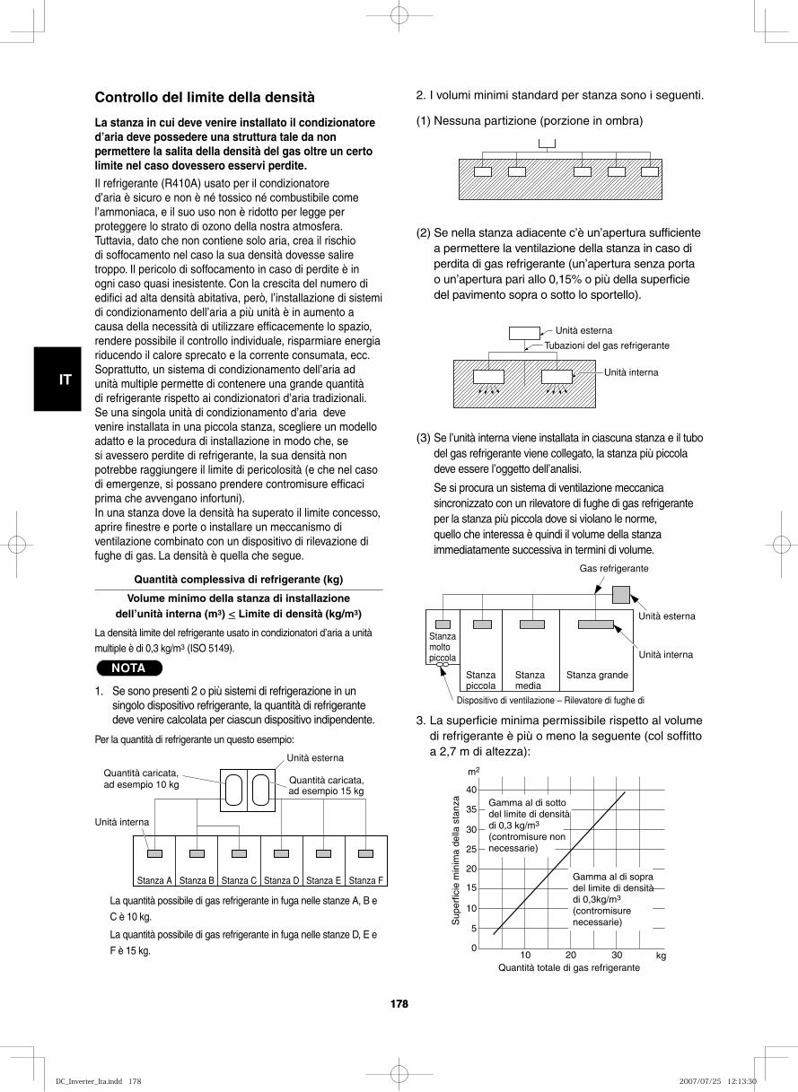
GB
FR
DE
IT
PT
GR
ES
178178
2. I volumi minimi standard per stanza sono i seguenti.
(1) Nessuna partizione (porzione in ombra)
(2) Se nella stanza adiacente c’è un’apertura sufficiente a permettere la ventilazione della stanza in caso di perdita di gas refrigerante (un’apertura senza porta o un’apertura pari allo 0,15% o più della superficie del pavimento sopra o sotto lo sportello).
(3) Se l’unità interna viene installata in ciascuna stanza e il tubo del gas refrigerante viene collegato, la stanza più piccola deve essere l’oggetto dell’analisi.
Se si procura un sistema di ventilazione meccanica sincronizzato con un rilevatore di fughe di gas refrigerante per la stanza più piccola dove si violano le norme, quello che interessa è quindi il volume della stanza immediatamente successiva in termini di volume.
3. La superficie minima permissibile rispetto al volume di refrigerante è più o meno la seguente (col soffitto a 2,7 m di altezza):
Controllo del limite della densità
La stanza in cui deve venire installato il condizionatore d’aria deve possedere una struttura tale da non permettere la salita della densità del gas oltre un certo limite nel caso dovessero esservi perdite.Il refrigerante (R410A) usato per il condizionatore d’aria è sicuro e non è né tossico né combustibile come l’ammoniaca, e il suo uso non è ridotto per legge per proteggere lo strato di ozono della nostra atmosfera. Tuttavia, dato che non contiene solo aria, crea il rischio di soffocamento nel caso la sua densità dovesse salire troppo. Il pericolo di soffocamento in caso di perdite è in ogni caso quasi inesistente. Con la crescita del numero di edifici ad alta densità abitativa, però, l’installazione di sistemi di condizionamento dell’aria a più unità è in aumento a causa della necessità di utilizzare efficacemente lo spazio, rendere possibile il controllo individuale, risparmiare energia riducendo il calore sprecato e la corrente consumata, ecc.Soprattutto, un sistema di condizionamento dell’aria ad unità multiple permette di contenere una grande quantità di refrigerante rispetto ai condizionatori d’aria tradizionali. Se una singola unità di condizionamento d’aria deve venire installata in una piccola stanza, scegliere un modello adatto e la procedura di installazione in modo che, se si avessero perdite di refrigerante, la sua densità non potrebbe raggiungere il limite di pericolosità (e che nel caso di emergenze, si possano prendere contromisure efficaci prima che avvengano infortuni). In una stanza dove la densità ha superato il limite concesso, aprire finestre e porte o installare un meccanismo di ventilazione combinato con un dispositivo di rilevazione di fughe di gas. La densità è quella che segue.
Quantità complessiva di refrigerante (kg)
Volume minimo della stanza di installazione dell’unità interna (m3) < Limite di densità (kg/m3)
La densità limite del refrigerante usato in condizionatori d’aria a unità multiple è di 0,3 kg/m3 (ISO 5149).
NOTA
1. Se sono presenti 2 o più sistemi di refrigerazione in un singolo dispositivo refrigerante, la quantità di refrigerante deve venire calcolata per ciascun dispositivo indipendente.
Per la quantità di refrigerante un questo esempio:
La quantità possibile di gas refrigerante in fuga nelle stanze A, B e
C è 10 kg.
La quantità possibile di gas refrigerante in fuga nelle stanze D, E e
F è 15 kg.
Unità esterna
Tubazioni del gas refrigerante
Unità interna
Quantità caricata, ad esempio 10 kg
Unità esterna
Unità interna
Stanza A Stanza B Stanza C Stanza D Stanza E Stanza F
Quantità caricata, ad esempio 15 kg
Gas refrigerante
Unità esterna
Stanza molto piccola Unità interna
Stanzapiccola
Stanzamedia
Stanza grande
Dispositivo di ventilazione – Rilevatore di fughe di
40
35
30
25
20
15
10
5
010 20 30
Quantità totale di gas refrigerante
Sup
erfic
ie m
inim
a de
lla s
tanz
a
m2
kg
Gamma al di sotto del limite di densità di 0,3 kg/m3
(contromisure nonnecessarie)
Gamma al di sopra del limite di densità di 0,3kg/m3
(contromisure necessarie)
DC_Inverter_Ita.indd 178DC_Inverter_Ita.indd 178 2007/07/25 12:13:302007/07/25 12:13:30
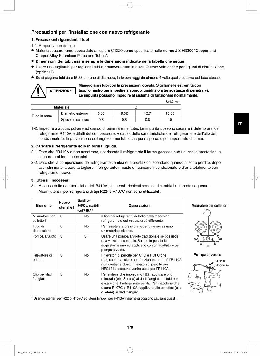
GB
FR
DE
IT
PT
GR
ES
179179
Utensili per Elemento R407C compatibili Osservazioni con l’R410A?
Misuratore per Sì No Il tipo dei refrigeranti, dell’olio della macchina collettori refrigerante e del misuratoreè differente.
Tubo di Sì No Per resistere a pressioni superiori è necessario depressione un materiale diverso.
Pompa a vuoto Sì Sì Usare una pompa a vuoto tradizionale se possiede una valvola di controllo. Se non lo possiede, acquistarne uno ed applicarlo con un adattatore per pompa a vuoto.
Rilevatore di Sì No I rilevatori di perdite per CFC e HCFC che perdite reagiscono al cloro non funzionano perché l’R410A non contiene cloro. I rilevatori di perdite per HFC134a possono venire usati per l’R410A.
Olio per dadi Sì No Per sistemi che impiegano R22, applicare olio flangiati minerale (olio Suniso) ai dadi flangiati dei tubi per evitare che il refrigerante perda. Per macchine che usano R407C o R410A, applicare olio sintetico (olio di etere) ai dadi flangiati.
1-2. Impedire a acqua, polvere ed ossido di penetrare nei tubo. Le impurità possono causare il deteriorarsi del refrigerante R410A e difetti del compressore. A causa delle caratteristiche del refrigerante e dell’olio del condizionatore, la prevenzione dell’ingresso nei tubi di acqua e sporco è più importante che mai.
2. Caricare il refrigerante solo in forma liquida.2-1. Dato che l’R410A è non azeotropo, ricaricando il refrigerante il forma gassosa può ridurne le prestazioni e
causare problemi meccanici. 2-2. Dato che la composizione del refrigerante cambia e le prestazioni scendono quando ci sono perdite, dopo
aver eliminato la perdita togliere il refrigerante rimasto e ricaricare il condizionatore d’aria totalmente con refrigerante nuovo.
3. Utensili necessari 3-1. A causa delle caratteristiche dell’R410A, gli utensili richiesti sono stati cambiati nel modo seguente. Alcuni utensili per refrigeranti di tipi R22- e R407C non sono utilizzabili.
Materiale O
Tubo in rame Diametro esterno 6,35 9,52 12,7 15,88
Spessore del muro 0,8 0,8 0,8 10
Precauzioni per l’installazione con nuovo refrigerante
1. Precauzioni riguardanti i tubi
1-1. Preparazione dei tubi● Materiale: usare rame deossidato al fosforo C1220 come specificato nelle norme JIS H3300 “Copper and
Copper Alloy Seamless Pipes and Tubes”. ● Dimensioni dei tubi: usare sempre le dimensioni indicate nella tabella che segue.● Usare una tagliatubi per tagliare i tubi e rimuovere tutte le bave. Questo vale anche per i giunti di distribuzione
(opzionali).● Se si piegano tubi da ø15,88 o meno di diametro, farlo con raggi da almeno 4 volte quello esterno del tubo stesso.
* Usando utensili per R22 o R407C ed utensili nuovi per R410A insieme si possono causare guasti.
Misuratore per collettori
Pompa a vuoto
UscitaIngresso
ATTENZIONE
Maneggiare i tubi con la precauzioni dovuta. Sigillarne le estremità con tappi o nastro per impedire a sporco, umidità o altre sostanze di penetrarvi. Le impurità possono impedire al sistema di funzionare normalmente.
Nuovo utensile?
Unità: mm
DC_Inverter_Ita.indd 179DC_Inverter_Ita.indd 179 2007/07/25 12:13:302007/07/25 12:13:30
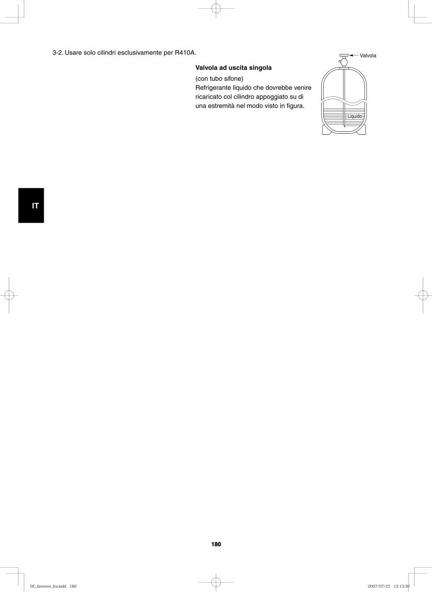
GB
FR
DE
IT
PT
GR
ES
180180
Valvola
Liquido
3-2. Usare solo cilindri esclusivamente per R410A.
Valvola ad uscita singola
(con tubo sifone)Refrigerante liquido che dovrebbe venire ricaricato col cilindro appoggiato su di una estremità nel modo visto in figura.
DC_Inverter_Ita.indd 180DC_Inverter_Ita.indd 180 2007/07/25 12:13:302007/07/25 12:13:30
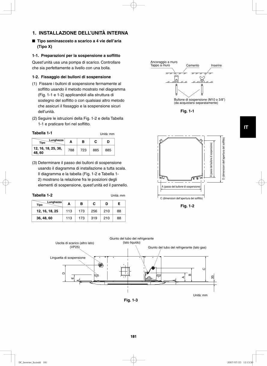
GB
FR
DE
IT
PT
GR
ES
181181
■ Tipo seminascosto a scarico a 4 vie dell’ aria (Tipo X)
1-1. Preparazioni per la sospensione a soffitto
Quest’unità usa una pompa di scarico. Controllare che sia perfettamente a livello con una bolla.
1-2. Fissaggio dei bulloni di sospensione
(1) Fissare i bulloni di sospensione fermamente al soffitto usando il metodo mostrato nel diagramma (Fig. 1-1 e 1-2) applicandoli alla struttura di sostegno del soffitto o con qualsiasi altro metodo che assicuri il fissaggio e la sospensione sicuri dell’unità.
(2) Seguire le istruzioni della Fig. 1-2 e della Tabella 1-1 e praticare fori nel soffitto.
Tabella 1-1 Unità: mm
(3) Determinare il passo dei bulloni di sospensione usando il diagramma di installazione a tutta scala. Il diagramma e la tabella (Fig. 1-2 e Tabella 1-2) mostrano la relazione fra le posizioni degli elementi di sospensione, quest’unità ed il pannello.
Tabella 1-2 Unità: mm
Fig. 1-1
Fig. 1-2
Fig. 1-3
Ancoraggio a muroTappo a muro Cemento Inserire
Bullone di sospensione (M10 o 3/8”)(da acquistarsi separatamente)
Tipo A B C D
788 723 885 885 12, 16, 18, 25, 36, 48, 60
Lunghezza
A B C D
113 173
173
210
210
256
36, 48, 60
12, 16, 18, 25
E
88
88 319 113
Tipo Lunghezza
D (d
imen
sion
i del
l’ape
rtura
del
sof
fitto
)
C (dimensioni dell’apertura del soffitto)
A (passo del bullone di sospensione)
B (p
asso
del
bul
lone
di s
ospe
nsio
ne)
E A B
C
D
35
Linguetta di sospensione
Giunto del tubo del refrigerante (lato liquido)
Giunto del tubo del refrigerante (lato gas) Uscita di scarico (altro lato)
(VP25)
1. INSTALLAZIONE DELL’UNITÀ INTERNA
Unità: mm
DC_Inverter_Ita.indd 181DC_Inverter_Ita.indd 181 2007/07/25 12:13:302007/07/25 12:13:30
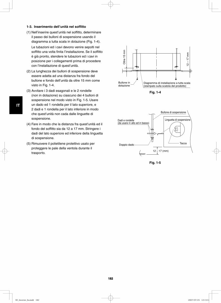
GB
FR
DE
IT
PT
GR
ES
182182
Fig. 1-4
Fig. 1-5
1-3. Inserimento dell’unità nel soffitto
(1) Nell’inserire quest’unità nel soffitto, determinare il passo dei bulloni di sospensione usando il diagramma a tutta scala in dotazione (Fig. 1-4).
Le tubazioni ed i cavi devono venire sepolti nel soffitto una volta finita l’installazione. Se il soffitto è già pronto, stendere le tubazioni ed i cavi in posizione per i collegamenti prima di procedere con l’installazione di quest’unità.
(2) La lunghezza dei bulloni di sospensione deve essere adatta ad una distanza fra fondo del bullone e fondo dell’unità da oltre 15 mm come visto in Fig. 1-4.
(3) Avvitare i 3 dadi esagonali e le 2 rondelle (non in dotazione) su ciascuno dei 4 bulloni di sospensione nel modo visto in Fig. 1-5. Usare un dado ed 1 rondella per il lato superiore, e 2 dadi e 1 rondella per il lato inferiore in modo che quest’unità non cada dalle linguette di sospensione.
(4) Fare in modo che la distanza fra quest’unità ed il fondo del soffitto sia da 12 a 17 mm. Stringere i dadi del lato superiore ed inferiore della linguetta di sospensione.
(5) Rimuovere il polietilene protettivo usato per proteggere le pale della ventola durante il trasporto.
Diagramma di installazione a tutta scala (stampato sulla scatola del prodotto)
Bullone in dotazione
Oltr
e 15
mm
12 –
17
mm
12 – 17 (mm)
Bullone di sospensione
Linguetta di sospensioneDadi e rondelle (da usare in alto ed in basso)
TaccaDoppio dado
DC_Inverter_Ita.indd 182DC_Inverter_Ita.indd 182 2007/07/25 12:13:312007/07/25 12:13:31
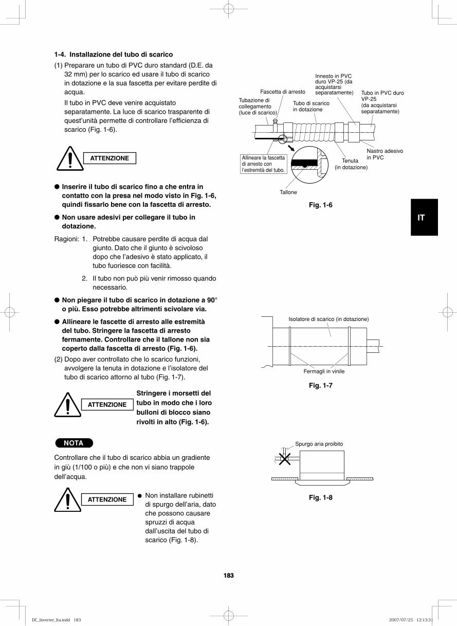
GB
FR
DE
IT
PT
GR
ES
183183
1-4. Installazione del tubo di scarico
(1) Preparare un tubo di PVC duro standard (D.E. da 32 mm) per lo scarico ed usare il tubo di scarico in dotazione e la sua fascetta per evitare perdite di acqua.
Il tubo in PVC deve venire acquistato separatamente. La luce di scarico trasparente di quest’unità permette di controllare l’efficienza di scarico (Fig. 1-6).
● Inserire il tubo di scarico fino a che entra in contatto con la presa nel modo visto in Fig. 1-6, quindi fissarlo bene con la fascetta di arresto.
● Non usare adesivi per collegare il tubo in dotazione.
Ragioni: 1. Potrebbe causare perdite di acqua dal giunto. Dato che il giunto è scivoloso dopo che l’adesivo è stato applicato, il tubo fuoriesce con facilità.
2. Il tubo non può più venir rimosso quando necessario.
● Non piegare il tubo di scarico in dotazione a 90° o più. Esso potrebbe altrimenti scivolare via.
● Allineare le fascette di arresto alle estremità del tubo. Stringere la fascetta di arresto fermamente. Controllare che il tallone non sia coperto dalla fascetta di arresto (Fig. 1-6).
(2) Dopo aver controllato che lo scarico funzioni, avvolgere la tenuta in dotazione e l’isolatore del tubo di scarico attorno al tubo (Fig. 1-7).
NOTA
Controllare che il tubo di scarico abbia un gradiente in giù (1/100 o più) e che non vi siano trappole dell’acqua.
ATTENZIONE
ATTENZIONE
Stringere i morsetti del tubo in modo che i loro bulloni di blocco siano rivolti in alto (Fig. 1-6).
ATTENZIONE● Non installare rubinetti
di spurgo dell’aria, dato che possono causare spruzzi di acqua dall’uscita del tubo di scarico (Fig. 1-8).
Fig. 1-6
Fig. 1-7
Fig. 1-8
Tallone
Fascetta di arresto
Tubo di scarico in dotazione
Tubazione di collegamento (luce di scarico)
Allineare la fascetta di arresto con l’estremità del tubo.
Tenuta (in dotazione)
Tubo in PVC duro VP-25 (da acquistarsi separatamente)
Innesto in PVC duro VP-25 (da acquistarsi separatamente)
Nastro adesivo in PVC
Fermagli in vinile
Isolatore di scarico (in dotazione)
Spurgo aria proibito
DC_Inverter_Ita.indd 183DC_Inverter_Ita.indd 183 2007/07/25 12:13:312007/07/25 12:13:31
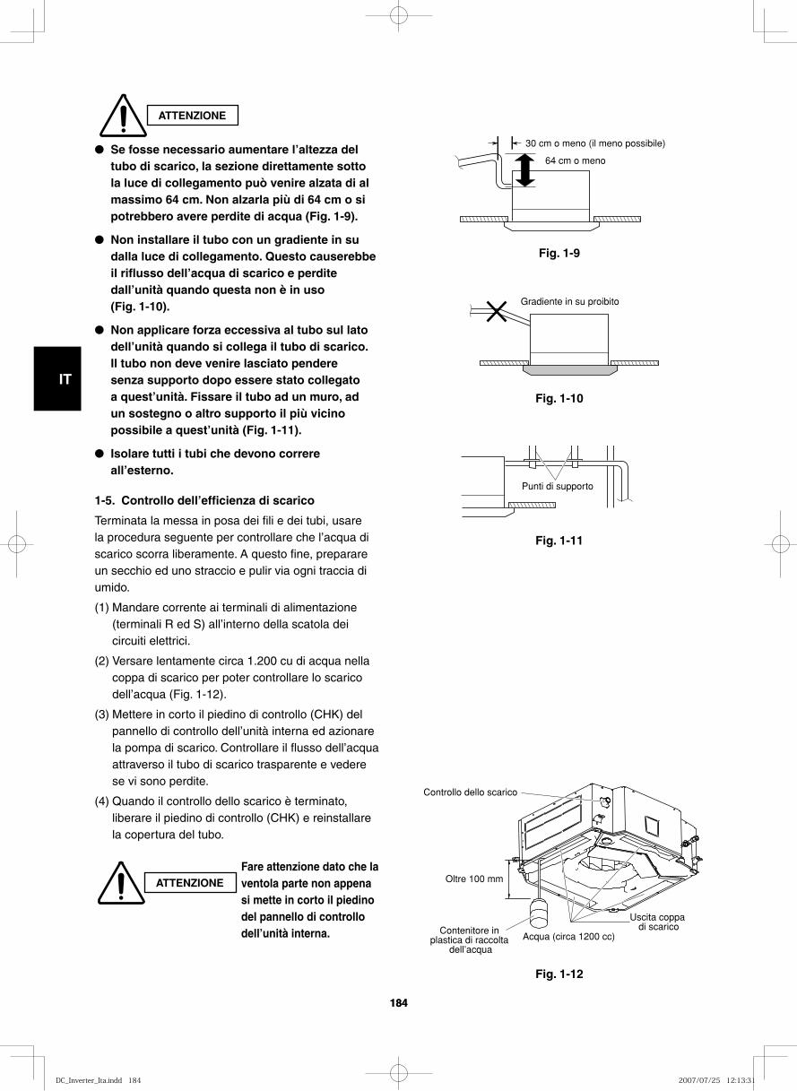
GB
FR
DE
IT
PT
GR
ES
184184
ATTENZIONE
Fig. 1-9
30 cm o meno (il meno possibile)
64 cm o meno
Fig. 1-10
Gradiente in su proibito
Fig. 1-11
Fig. 1-12
Punti di supporto
Acqua (circa 1200 cc)
Oltre 100 mm
Uscita coppa di scarico
Controllo dello scarico
Contenitore in plastica di raccolta
dell’acqua
ATTENZIONE
Fare attenzione dato che la ventola parte non appena si mette in corto il piedino del pannello di controllo dell’unità interna.
● Se fosse necessario aumentare l’altezza del tubo di scarico, la sezione direttamente sotto la luce di collegamento può venire alzata di al massimo 64 cm. Non alzarla più di 64 cm o si potrebbero avere perdite di acqua (Fig. 1-9).
● Non installare il tubo con un gradiente in su dalla luce di collegamento. Questo causerebbe il riflusso dell’acqua di scarico e perdite dall’unità quando questa non è in uso (Fig. 1-10).
● Non applicare forza eccessiva al tubo sul lato dell’unità quando si collega il tubo di scarico. Il tubo non deve venire lasciato pendere senza supporto dopo essere stato collegato a quest’unità. Fissare il tubo ad un muro, ad un sostegno o altro supporto il più vicino possibile a quest’unità (Fig. 1-11).
● Isolare tutti i tubi che devono correre all’esterno.
1-5. Controllo dell’efficienza di scarico
Terminata la messa in posa dei fili e dei tubi, usare la procedura seguente per controllare che l’acqua di scarico scorra liberamente. A questo fine, preparare un secchio ed uno straccio e pulir via ogni traccia di umido.
(1) Mandare corrente ai terminali di alimentazione (terminali R ed S) all’interno della scatola dei circuiti elettrici.
(2) Versare lentamente circa 1.200 cu di acqua nella coppa di scarico per poter controllare lo scarico dell’acqua (Fig. 1-12).
(3) Mettere in corto il piedino di controllo (CHK) del pannello di controllo dell’unità interna ed azionare la pompa di scarico. Controllare il flusso dell’acqua attraverso il tubo di scarico trasparente e vedere se vi sono perdite.
(4) Quando il controllo dello scarico è terminato, liberare il piedino di controllo (CHK) e reinstallare la copertura del tubo.
DC_Inverter_Ita.indd 184DC_Inverter_Ita.indd 184 2007/07/25 12:13:312007/07/25 12:13:31
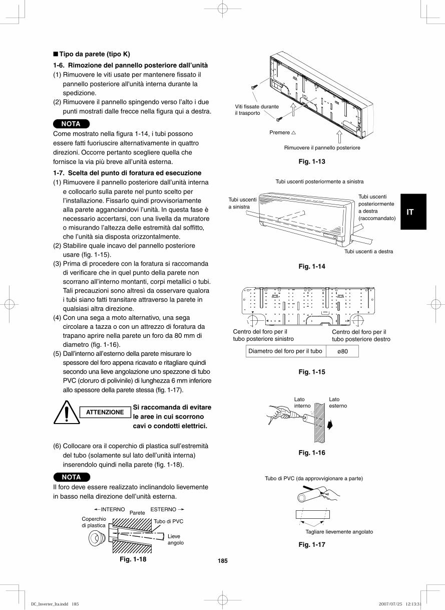
GB
FR
DE
IT
PT
GR
ES
185
■ Tipo da parete (tipo K)
1-6. Rimozione del pannello posteriore dall’unità(1) Rimuovere le viti usate per mantenere fissato il
pannello posteriore all'unità interna durante la spedizione.
(2) Rimuovere il pannello spingendo verso l’alto i due punti mostrati dalle frecce nella figura qui a destra.
NOTACome mostrato nella figura 1-14, i tubi possono essere fatti fuoriuscire alternativamente in quattro direzioni. Occorre pertanto scegliere quella che fornisce la via più breve all’unità esterna.
1-7. Scelta del punto di foratura ed esecuzione(1) Rimuovere il pannello posteriore dall’unità interna
e collocarlo sulla parete nel punto scelto per l’installazione. Fissarlo quindi provvisoriamente alla parete agganciandovi l’unità. In questa fase è necessario accertarsi, con una livella da muratore o misurando l’altezza delle estremità dal soffitto, che l’unità sia disposta orizzontalmente.
(2) Stabilire quale incavo del pannello posteriore usare (fig. 1-15).
(3) Prima di procedere con la foratura si raccomanda di verificare che in quel punto della parete non scorrano all’interno montanti, corpi metallici o tubi. Tali precauzioni sono altresì da osservare qualora i tubi siano fatti transitare attraverso la parete in qualsiasi altra direzione.
(4) Con una sega a moto alternativo, una sega circolare a tazza o con un attrezzo di foratura da trapano aprire nella parete un foro da 80 mm di diametro (fig. 1-16).
(5) Dall’interno all’esterno della parete misurare lo spessore del foro appena ricavato e ritagliare quindi secondo una lieve angolazione uno spezzone di tubo PVC (cloruro di polivinile) di lunghezza 6 mm inferiore allo spessore della parete stessa (fig. 1-17).
(6) Collocare ora il coperchio di plastica sull’estremità del tubo (solamente sul lato dell’unità interna) inserendolo quindi nella parete (fig. 1-18).
NOTAIl foro deve essere realizzato inclinandolo lievemente in basso nella direzione dell’unità esterna.
Fig. 1-13
Fig. 1-14
Fig. 1-15
Fig. 1-16
Fig. 1-17Fig. 3-18
ATTENZIONESi raccomanda di evitare le aree in cui scorrono cavi o condotti elettrici.
Coperchio di plastica
INTERNOParete
Lieve angolo
Tubo di PVC
ESTERNO
Tagliare lievemente angolato
Tubo di PVC (da approvvigionare a parte)
Lato interno
Lato esterno
Centro del foro per il tubo posteriore sinistro
Centro del foro per il tubo posteriore destro
Diametro del foro per il tubo ø80
Tubi uscenti a sinistra
Tubi uscenti posteriormente a destra (raccomandato)
Tubi uscenti a destra
Tubi uscenti posteriormente a sinistra
Rimuovere il pannello posteriore
Premere
Viti fissate durante il trasporto
Fig. 1-18
DC_Inverter_Ita.indd 185DC_Inverter_Ita.indd 185 2007/07/25 12:13:312007/07/25 12:13:31
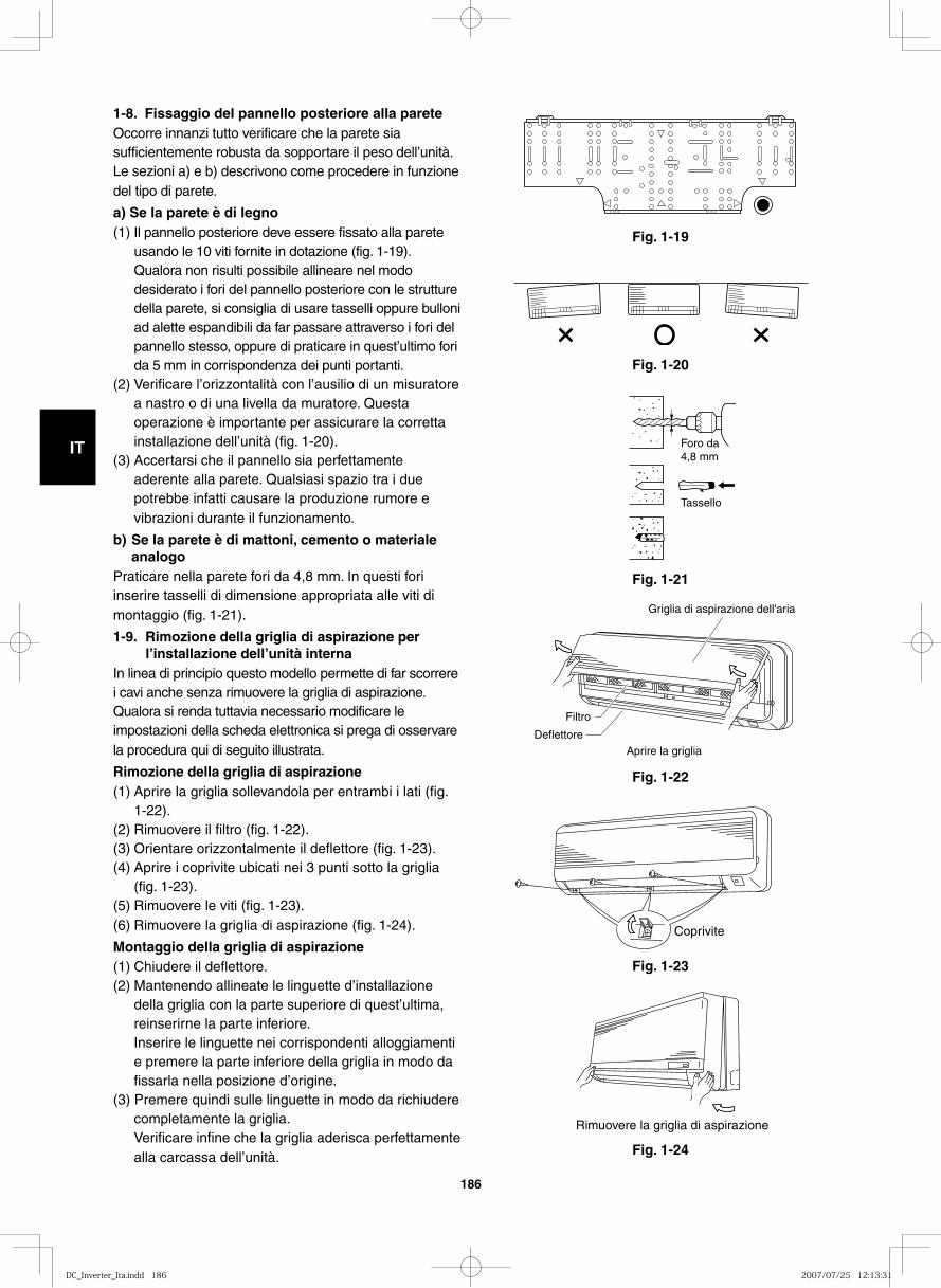
GB
FR
DE
IT
PT
GR
ES
186
Fig. 1-19
1-8. Fissaggio del pannello posteriore alla pareteOccorre innanzi tutto verificare che la parete sia sufficientemente robusta da sopportare il peso dell’unità. Le sezioni a) e b) descrivono come procedere in funzione del tipo di parete.
a) Se la parete è di legno(1) Il pannello posteriore deve essere fissato alla parete
usando le 10 viti fornite in dotazione (fig. 1-19).Qualora non risulti possibile allineare nel modo desiderato i fori del pannello posteriore con le strutture della parete, si consiglia di usare tasselli oppure bulloni ad alette espandibili da far passare attraverso i fori del pannello stesso, oppure di praticare in quest’ultimo fori da 5 mm in corrispondenza dei punti portanti.
(2) Verificare l’orizzontalità con l’ausilio di un misuratore a nastro o di una livella da muratore. Questa operazione è importante per assicurare la corretta installazione dell’unità (fig. 1-20).
(3) Accertarsi che il pannello sia perfettamente aderente alla parete. Qualsiasi spazio tra i due potrebbe infatti causare la produzione rumore e vibrazioni durante il funzionamento.
b) Se la parete è di mattoni, cemento o materiale analogo
Praticare nella parete fori da 4,8 mm. In questi fori inserire tasselli di dimensione appropriata alle viti di montaggio (fig. 1-21).
1-9. Rimozione della griglia di aspirazione per l’installazione dell’unità interna
In linea di principio questo modello permette di far scorrere i cavi anche senza rimuovere la griglia di aspirazione. Qualora si renda tuttavia necessario modificare le impostazioni della scheda elettronica si prega di osservare la procedura qui di seguito illustrata.
Rimozione della griglia di aspirazione(1) Aprire la griglia sollevandola per entrambi i lati (fig.
1-22).(2) Rimuovere il filtro (fig. 1-22).(3) Orientare orizzontalmente il deflettore (fig. 1-23).(4) Aprire i coprivite ubicati nei 3 punti sotto la griglia
(fig. 1-23).(5) Rimuovere le viti (fig. 1-23).(6) Rimuovere la griglia di aspirazione (fig. 1-24).
Montaggio della griglia di aspirazione(1) Chiudere il deflettore.(2) Mantenendo allineate le linguette d’installazione
della griglia con la parte superiore di quest’ultima, reinserirne la parte inferiore.Inserire le linguette nei corrispondenti alloggiamenti e premere la parte inferiore della griglia in modo da fissarla nella posizione d’origine.
(3) Premere quindi sulle linguette in modo da richiudere completamente la griglia.Verificare infine che la griglia aderisca perfettamente alla carcassa dell’unità.
Fig. 1-20
Fig. 1-21
Fig. 1-22
Fig. 1-23
Fig. 1-24
Foro da 4,8 mm
Tassello
Griglia di aspirazione dell'aria
Filtro
Deflettore
Aprire la griglia
Coprivite
Rimuovere la griglia di aspirazione
DC_Inverter_Ita.indd 186DC_Inverter_Ita.indd 186 2007/07/25 12:13:312007/07/25 12:13:31
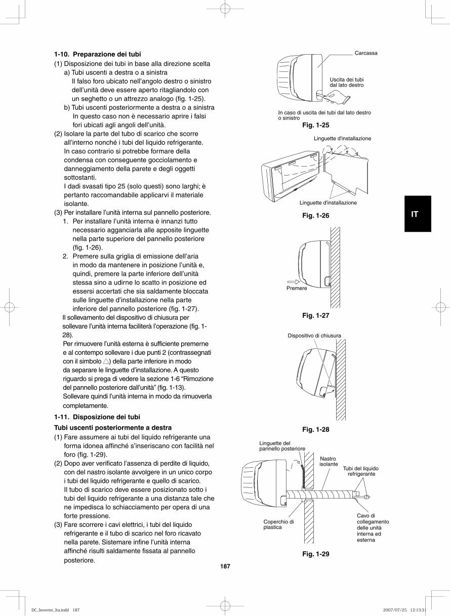
GB
FR
DE
IT
PT
GR
ES
187
1-10. Preparazione dei tubi(1) Disposizione dei tubi in base alla direzione scelta a) Tubi uscenti a destra o a sinistra
Il falso foro ubicato nell’angolo destro o sinistro dell’unità deve essere aperto ritagliandolo con un seghetto o un attrezzo analogo (fig. 1-25).
b) Tubi uscenti posteriormente a destra o a sinistraIn questo caso non è necessario aprire i falsi fori ubicati agli angoli dell’unità.
(2) Isolare la parte del tubo di scarico che scorre all’interno nonché i tubi del liquido refrigerante.In caso contrario si potrebbe formare della condensa con conseguente gocciolamento e danneggiamento della parete e degli oggetti sottostanti. I dadi svasati tipo 25 (solo questi) sono larghi; è pertanto raccomandabile applicarvi il materiale isolante.
(3) Per installare l’unità interna sul pannello posteriore.1. Per installare l’unità interna è innanzi tutto
necessario agganciarla alle apposite linguette nella parte superiore del pannello posteriore (fig. 1-26).
2. Premere sulla griglia di emissione dell’aria in modo da mantenere in posizione l’unità e, quindi, premere la parte inferiore dell’unità stessa sino a udirne lo scatto in posizione ed essersi accertati che sia saldamente bloccata sulle linguette d’installazione nella parte inferiore del pannello posteriore (fig. 1-27).
Il sollevamento del dispositivo di chiusura per sollevare l’unità interna faciliterà l’operazione (fig. 1-28).Per rimuovere l’unità esterna è sufficiente premerne e al contempo sollevare i due punti 2 (contrassegnati con il simbolo ▲▲) della parte inferiore in modo da separare le linguette d’installazione. A questo riguardo si prega di vedere la sezione 1-6 “Rimozione del pannello posteriore dall’unità” (fig. 1-13).Sollevare quindi l’unità interna in modo da rimuoverla completamente.
1-11. Disposizione dei tubi
Tubi uscenti posteriormente a destra(1) Fare assumere ai tubi del liquido refrigerante una
forma idonea affinché s’inseriscano con facilità nel foro (fig. 1-29).
(2) Dopo aver verificato l’assenza di perdite di liquido, con del nastro isolante avvolgere in un unico corpo i tubi del liquido refrigerante e quello di scarico.Il tubo di scarico deve essere posizionato sotto i tubi del liquido refrigerante a una distanza tale che ne impedisca lo schiacciamento per opera di una forte pressione.
(3) Fare scorrere i cavi elettrici, i tubi del liquido refrigerante e il tubo di scarico nel foro ricavato nella parete. Sistemare infine l’unità interna affinché risulti saldamente fissata al pannello posteriore.
Carcassa
Uscita dei tubi dal lato destro
In caso di uscita dei tubi dal lato destro o sinistro
Fig. 1-26
Linguette d'installazione
Linguette d'installazione
Fig. 1-27
Premere
Fig. 1-28
Dispositivo di chiusura
Fig. 1-29
Nastro isolante
Tubi del liquido refrigerante
Linguette del pannello posteriore
Coperchio di plastica
Cavo di collegamento delle unità interna ed esterna
Fig. 1-25
DC_Inverter_Ita.indd 187DC_Inverter_Ita.indd 187 2007/07/25 12:13:312007/07/25 12:13:31
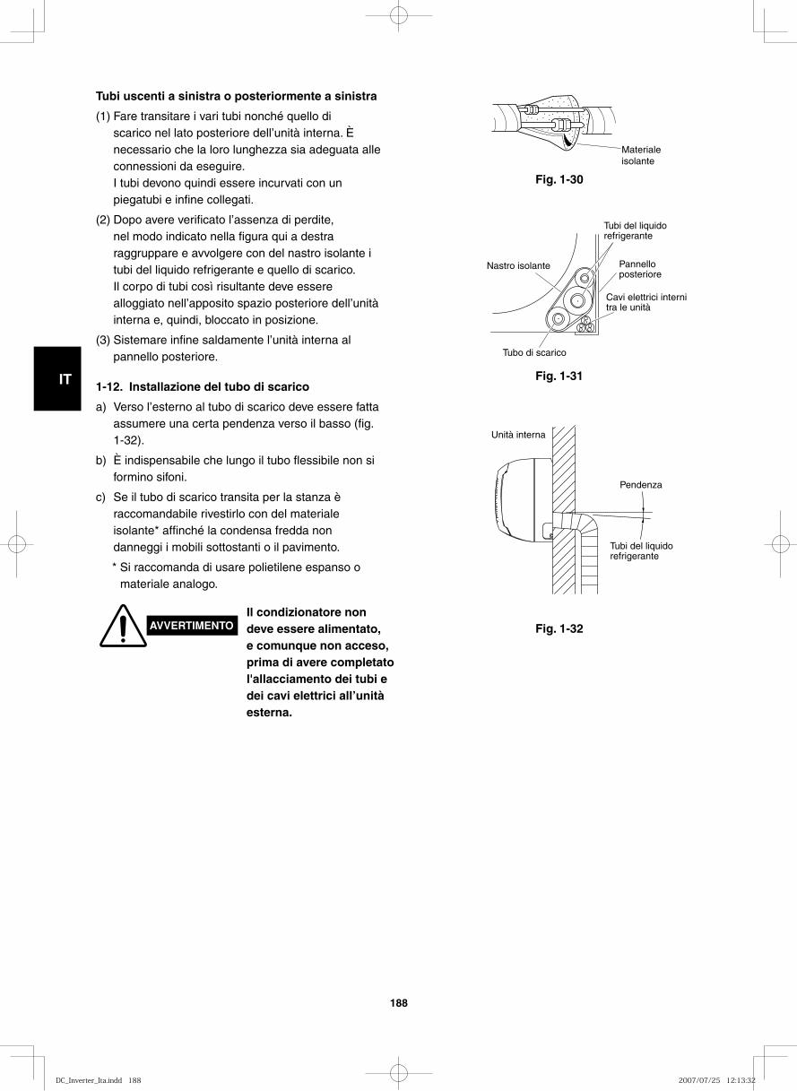
GB
FR
DE
IT
PT
GR
ES
188
Fig. 1-32
Fig. 1-30
Materiale isolante
Fig. 1-31
Nastro isolante Pannello posteriore
Cavi elettrici interni tra le unità
Tubi del liquido refrigerante
Tubo di scarico
Unità interna
Pendenza
Tubi del liquido refrigerante
1-12. Installazione del tubo di scarico
a) Verso l’esterno al tubo di scarico deve essere fatta assumere una certa pendenza verso il basso (fig. 1-32).
b) È indispensabile che lungo il tubo flessibile non si formino sifoni.
c) Se il tubo di scarico transita per la stanza è raccomandabile rivestirlo con del materiale isolante* affinché la condensa fredda non danneggi i mobili sottostanti o il pavimento.
* Si raccomanda di usare polietilene espanso o materiale analogo.
Tubi uscenti a sinistra o posteriormente a sinistra
(1) Fare transitare i vari tubi nonché quello di scarico nel lato posteriore dell’unità interna. È necessario che la loro lunghezza sia adeguata alle connessioni da eseguire.I tubi devono quindi essere incurvati con un piegatubi e infine collegati.
(2) Dopo avere verificato l’assenza di perdite, nel modo indicato nella figura qui a destra raggruppare e avvolgere con del nastro isolante i tubi del liquido refrigerante e quello di scarico. Il corpo di tubi così risultante deve essere alloggiato nell’apposito spazio posteriore dell’unità interna e, quindi, bloccato in posizione.
(3) Sistemare infine saldamente l’unità interna al pannello posteriore.
AVVERTIMENTOIl condizionatore non deve essere alimentato, e comunque non acceso, prima di avere completato l'allacciamento dei tubi e dei cavi elettrici all’unità esterna.
DC_Inverter_Ita.indd 188DC_Inverter_Ita.indd 188 2007/07/25 12:13:322007/07/25 12:13:32
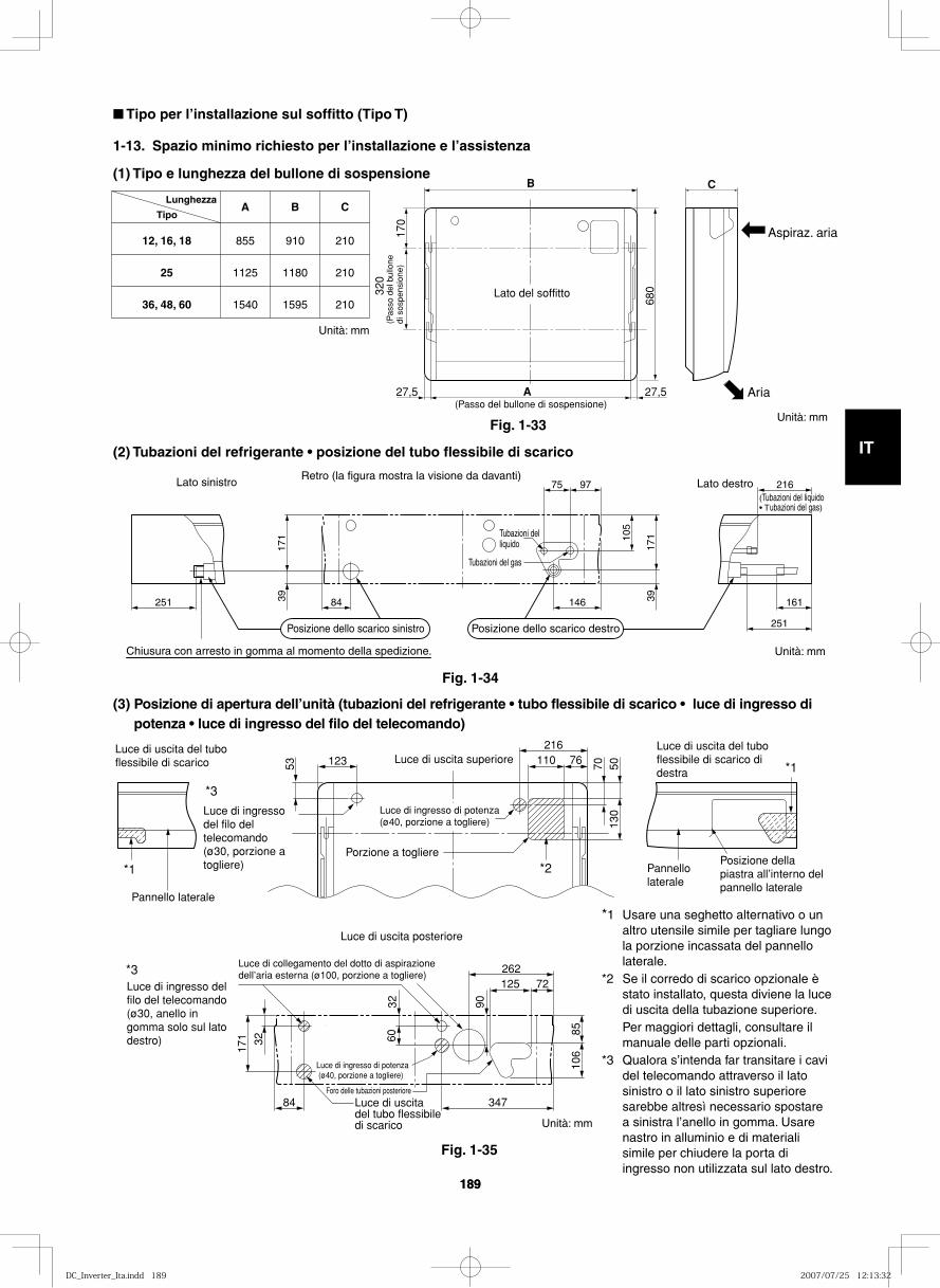
GB
FR
DE
IT
PT
GR
ES
189189
■ Tipo per l’installazione sul soffitto (Tipo T)
1-13. Spazio minimo richiesto per l’installazione e l’assistenza
(1) Tipo e lunghezza del bullone di sospensione
12, 16, 18
25
36, 48, 60
855
1125
1540
910
1180
1595
210
210
210
A B C Lunghezza
Tipo
B C
A17
0
320
680
27,5 27,5
Lato del soffitto
(Passo del bullone di sospensione)
(Pas
so d
el b
ullo
nedi
sos
pens
ione
)
Aspiraz. aria
Aria
(2) Tubazioni del refrigerante • posizione del tubo flessibile di scarico
(3) Posizione di apertura dell’unità (tubazioni del refrigerante • tubo flessibile di scarico • luce di ingresso di potenza • luce di ingresso del filo del telecomando)
251 84 146 161
75 97 216
39
39
171 10
5
171
251
Tubazioni del gas
Tubazioni del liquido
Lato destro Lato sinistro Retro (la figura mostra la visione da davanti)
Chiusura con arresto in gomma al momento della spedizione.
Posizione dello scarico sinistro Posizione dello scarico destro
(Tubazioni del liquido • Tubazioni del gas)
53 70123 110 76216
5013
0
Luce di uscita del tubo flessibile di scarico
Luce di uscita del tubo flessibile di scarico di destra
Luce di uscita superiore
Luce di ingresso del filo del telecomando (ø30, porzione a togliere)
Luce di ingresso di potenza (ø40, porzione a togliere)
Luce di ingresso di potenza (ø40, porzione a togliere)
Porzione a togliere
Pannello laterale
Posizione della piastra all’interno del pannello laterale
Pannello laterale
Luce di uscita del tubo flessibile di scarico
Foro delle tubazioni posteriore
84
32
3260
171
347
125 72
8510
6
90
262
Luce di ingresso del filo del telecomando(ø30, anello in gomma solo sul lato destro)
Luce di collegamento del dotto di aspirazione dell’aria esterna (ø100, porzione a togliere)
Luce di uscita posteriore
*3
*1
*1
*2
*3
Fig. 1-33
Fig. 1-34
Unità: mm
Unità: mm
Unità: mm
Unità: mm
Fig. 1-35
*1 Usare una seghetto alternativo o un altro utensile simile per tagliare lungo la porzione incassata del pannello laterale.
*2 Se il corredo di scarico opzionale è stato installato, questa diviene la luce di uscita della tubazione superiore.
Per maggiori dettagli, consultare il manuale delle parti opzionali.
*3 Qualora s’intenda far transitare i cavi del telecomando attraverso il lato sinistro o il lato sinistro superiore sarebbe altresì necessario spostare a sinistra l’anello in gomma. Usare nastro in alluminio e di materiali simile per chiudere la porta di ingresso non utilizzata sul lato destro.
DC_Inverter_Ita.indd 189DC_Inverter_Ita.indd 189 2007/07/25 12:13:322007/07/25 12:13:32
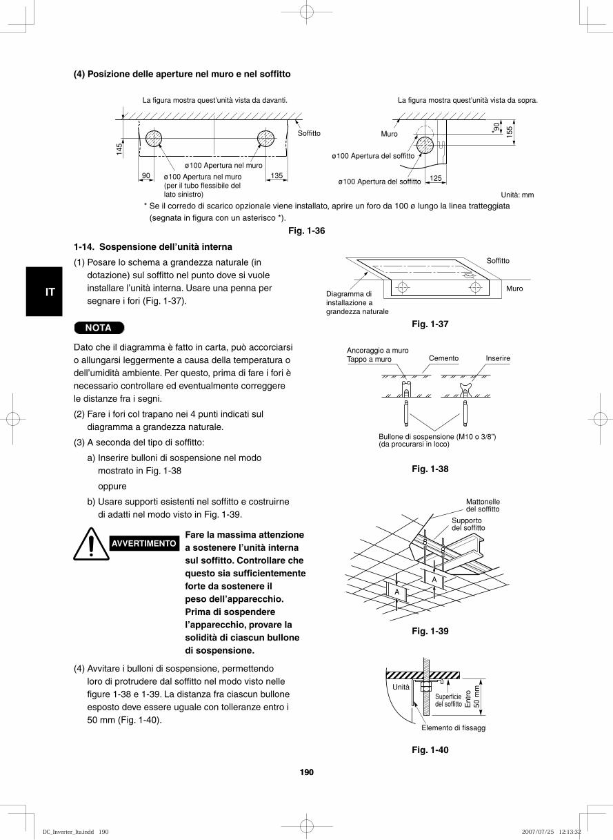
GB
FR
DE
IT
PT
GR
ES
190190
(4) Posizione delle aperture nel muro e nel soffitto
90
145
135 125
15590
*
La figura mostra quest’unità vista da davanti. La figura mostra quest’unità vista da sopra.
ø100 Apertura nel muro (per il tubo flessibile del lato sinistro)
ø100 Apertura nel muroø100 Apertura del soffitto
ø100 Apertura del soffitto
MuroSoffitto
Diagramma di installazione a grandezza naturale
Muro
Soffitto
Fig. 1-37
Fig. 1-36
Fig. 1-38
1-14. Sospensione dell’unità interna
(1) Posare lo schema a grandezza naturale (in dotazione) sul soffitto nel punto dove si vuole installare l’unità interna. Usare una penna per segnare i fori (Fig. 1-37).
NOTA
Dato che il diagramma è fatto in carta, può accorciarsi o allungarsi leggermente a causa della temperatura o dell’umidità ambiente. Per questo, prima di fare i fori è necessario controllare ed eventualmente correggere le distanze fra i segni.
(2) Fare i fori col trapano nei 4 punti indicati sul diagramma a grandezza naturale.
(3) A seconda del tipo di soffitto:
a) Inserire bulloni di sospensione nel modo mostrato in Fig. 1-38
oppure
b) Usare supporti esistenti nel soffitto e costruirne di adatti nel modo visto in Fig. 1-39.
AVVERTIMENTOFare la massima attenzione a sostenere l’unità interna sul soffitto. Controllare che questo sia sufficientemente forte da sostenere il peso dell’apparecchio. Prima di sospendere l’apparecchio, provare la solidità di ciascun bullone di sospensione.
(4) Avvitare i bulloni di sospensione, permettendo loro di protrudere dal soffitto nel modo visto nelle figure 1-38 e 1-39. La distanza fra ciascun bullone esposto deve essere uguale con tolleranze entro i 50 mm (Fig. 1-40).
Ancoraggio a muroTappo a muro Cemento Inserire
Bullone di sospensione (M10 o 3/8”)(da procurarsi in loco)
Fig. 1-39
Fig. 1-40
Mattonelle del soffitto
Supporto del soffitto
A
A
UnitàSuperficie del soffitto
Elemento di fissaggi
Ent
ro50
mm
* Se il corredo di scarico opzionale viene installato, aprire un foro da 100 ø lungo la linea tratteggiata (segnata in figura con un asterisco *).
Unità: mm
DC_Inverter_Ita.indd 190DC_Inverter_Ita.indd 190 2007/07/25 12:13:322007/07/25 12:13:32
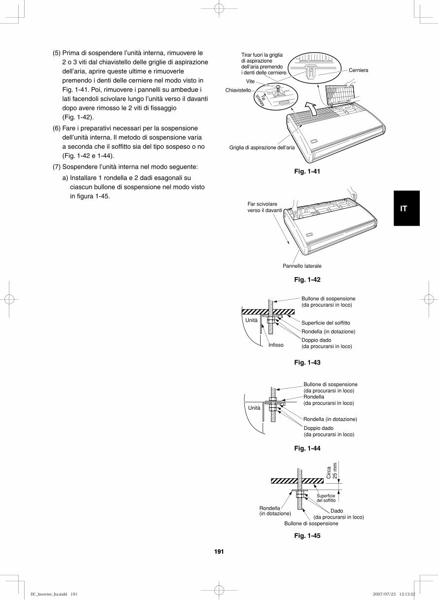
GB
FR
DE
IT
PT
GR
ES
191191
Fig. 1-41Far
scivolare
Cerniera
Griglia di aspirazione dell’aria
Tirar fuori la griglia di aspirazione dell’aria premendo i denti delle cerniere.
Vite
Chiavistello
Fig. 1-42
Far scivolare verso il davanti
Pannello laterale
Fig. 1-43
Unità
Bullone di sospensione (da procurarsi in loco)
Superficie del soffitto
Rondella (in dotazione)
Doppio dado(da procurarsi in loco)Infisso
Fig. 1-44
Unità
Bullone di sospensione (da procurarsi in loco)Rondella (da procurarsi in loco)
Rondella (in dotazione)
Doppio dado (da procurarsi in loco)
Fig. 1-45
Superficie del soffitto
Circ
a 25
mm
Bullone di sospensione
Rondella (in dotazione) Dado
(da procurarsi in loco)
(5) Prima di sospendere l’unità interna, rimuovere le 2 o 3 viti dal chiavistello delle griglie di aspirazione dell’aria, aprire queste ultime e rimuoverle premendo i denti delle cerniere nel modo visto in Fig. 1-41. Poi, rimuovere i pannelli su ambedue i lati facendoli scivolare lungo l’unità verso il davanti dopo avere rimosso le 2 viti di fissaggio (Fig. 1-42).
(6) Fare i preparativi necessari per la sospensione dell’unità interna. Il metodo di sospensione varia a seconda che il soffitto sia del tipo sospeso o no (Fig. 1-42 e 1-44).
(7) Sospendere l’unità interna nel modo seguente:
a) Installare 1 rondella e 2 dadi esagonali su ciascun bullone di sospensione nel modo visto in figura 1-45.
DC_Inverter_Ita.indd 191DC_Inverter_Ita.indd 191 2007/07/25 12:13:322007/07/25 12:13:32
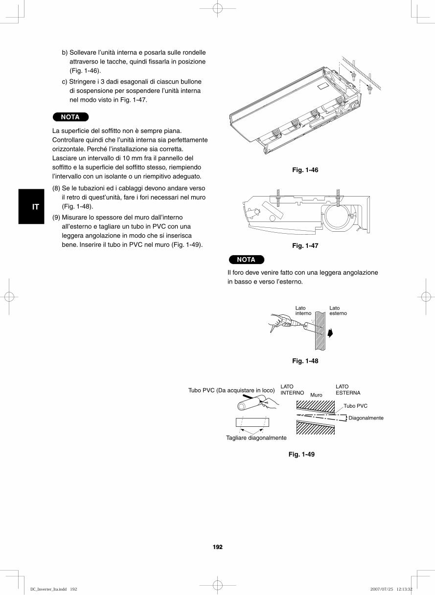
GB
FR
DE
IT
PT
GR
ES
192192
Fig. 1-46
Fig. 1-47
Fig. 1-48
Latointerno
Latoesterno
Fig. 1-49
Tubo PVC (Da acquistare in loco)
Tagliare diagonalmente
LATOINTERNO
LATOESTERNAMuro
Diagonalmente
Tubo PVC
b) Sollevare l’unità interna e posarla sulle rondelle attraverso le tacche, quindi fissarla in posizione (Fig. 1-46).
c) Stringere i 3 dadi esagonali di ciascun bullone di sospensione per sospendere l’unità interna nel modo visto in Fig. 1-47.
NOTA
La superficie del soffitto non è sempre piana. Controllare quindi che l’unità interna sia perfettamente orizzontale. Perché l’installazione sia corretta. Lasciare un intervallo di 10 mm fra il pannello del soffitto e la superficie del soffitto stesso, riempiendo l’intervallo con un isolante o un riempitivo adeguato.
(8) Se le tubazioni ed i cablaggi devono andare verso il retro di quest’unità, fare i fori necessari nel muro (Fig. 1-48).
(9) Misurare lo spessore del muro dall’interno all’esterno e tagliare un tubo in PVC con una leggera angolazione in modo che si inserisca bene. Inserire il tubo in PVC nel muro (Fig. 1-49).
NOTA
Il foro deve venire fatto con una leggera angolazione in basso e verso l’esterno.
DC_Inverter_Ita.indd 192DC_Inverter_Ita.indd 192 2007/07/25 12:13:322007/07/25 12:13:32

GB
FR
DE
IT
PT
GR
ES
193193
1-15. Dotto per l’aria fresca
C’è una luce di collegamento per un dotto (foro con pannello a togliere) nel retro a destra del pannello superiore dell’unità interna per trarre in essa aria fresca. Se fosse necessario aspirare aria fresca, rimuovere la copertura aprendo così il foro e collegando il dotto all’unità interna attraverso la luce di collegamento (Fig. 1-50).
1-16. Conformazione e messa in posa dei tubi
● Le posizioni di collegamento dei tubi del refrigerante sono mostrate nella figura qui sotto. (Le tubazioni possono venire messe in posa in 3 direzioni diverse.)
* Quando si mette in posa un tubo verso l’alto o la destra, togliere le parti appropriate e tagliare delle tacche nel pannello laterale nel modo visto in Fig. 1-35.
* Nel mettere in posa le tubazioni attraverso l’alto è necessario fare uso del corredo opzionale del tubo a L.
1-17. Installazione del tubo di scarico
● Preparare il tubo in PVC standard di scarico e collegarlo al tubo di scarico dell’unità interna con i fermatubi in dotazione in modo da prevenire perdite di acqua.
(1) Collegamento dei tubo flessibile di scarico
● Il tubo flessibile di scarico viene collegato sotto il tubo del refrigerante.
(2) Installazione del tubo flessibile di scarico
● Per installare il tubo flessibile di scarico, per prima cosa posare 1 delle 2 fascette fermatubi sopra la luce di scarico dell’unità e l’altra sopra il tubo di PVC duro (non in dotazione). Collegare poi ambedue le estremità al tubo flessibile di scarico in dotazione.
● Sul lato di scarico, prendere la fascetta fermatubi con delle pinze ed inserire il tubo flessibile di scarico fino in fondo fino alla base.
Luce di ingresso del filo del telecomando(ø30, anello in gomma solo sul lato destro)
Luce di collegamento del dotto di aspirazione dell’aria esterna (ø100, porzione a togliere)
Luce di uscita posteriore
Luce di ingresso di potenza (ø40, porzione a togliere)
Foro delle tubazioni posteriore
Luce di uscita del tubo flessibile di scarico
Fig. 1-50
Copertura posteriore
ATTENZIONE● Fissare il tutto in
modo che la fascetta fermatubi si trovi sul lato della luce di scarico (Fig. 1-54).
● Fissare le fascette del tubo flessibile in modo che ciascuna si trovi a circa da 5 a 25 mm dall’estremità del tubo flessibile di scarico in dotazione.
Se le tubazioni devono venire messe in posa insieme, usare un coltello da lavoro o un altro utensile simile per tagliare la porzione del coperchio posteriore indicata dall’ombreggiatura nella figura qui sotto in modo che corrisponda alle posizioni dei tubi. Tirar quindi fuori i tubi.
Fig. 1-51 Fig. 1-52
DC_Inverter_Ita.indd 193DC_Inverter_Ita.indd 193 2007/07/25 12:13:322007/07/25 12:13:32
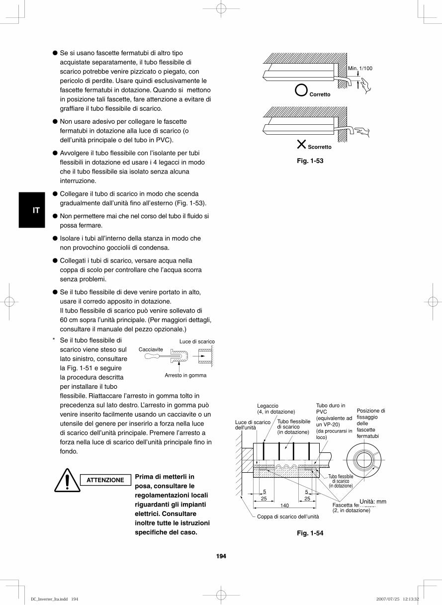
GB
FR
DE
IT
PT
GR
ES
194194
14025 25
55
Posizione di fissaggio delle fascette fermatubi
Tubo flessibile di scarico
(in dotazione)
Fascetta fermatubi (2, in dotazione)
Coppa di scarico dell’unità
Luce di scarico dell'unità
Tubo flessibile di scarico (in dotazione)
Legaccio (4, in dotazione)
Tubo duro in PVC (equivalente ad un VP-20) (da procurarsi in loco)
Fig. 1-54
Corretto
Min. 1/100
Scorretto
Fig. 1-53
● Se si usano fascette fermatubi di altro tipo acquistate separatamente, il tubo flessibile di scarico potrebbe venire pizzicato o piegato, con pericolo di perdite. Usare quindi esclusivamente le fascette fermatubi in dotazione. Quando si mettono in posizione tali fascette, fare attenzione a evitare di graffiare il tubo flessibile di scarico.
● Non usare adesivo per collegare le fascette fermatubi in dotazione alla luce di scarico (o dell’unità principale o del tubo in PVC).
● Avvolgere il tubo flessibile con l’isolante per tubi flessibili in dotazione ed usare i 4 legacci in modo che il tubo flessibile sia isolato senza alcuna interruzione.
● Collegare il tubo di scarico in modo che scenda gradualmente dall’unità fino all’esterno (Fig. 1-53).
● Non permettere mai che nel corso del tubo il fluido si possa fermare.
● Isolare i tubi all’interno della stanza in modo che non provochino gocciolii di condensa.
● Collegati i tubi di scarico, versare acqua nella coppa di scolo per controllare che l’acqua scorra senza problemi.
● Se il tubo flessibile di deve venire portato in alto, usare il corredo apposito in dotazione.
Il tubo flessibile di scarico può venire sollevato di 60 cm sopra l’unità principale. (Per maggiori dettagli, consultare il manuale del pezzo opzionale.)
* Se il tubo flessibile di scarico viene steso sul lato sinistro, consultare la Fig. 1-51 e seguire la procedura descritta per installare il tubo flessibile. Riattaccare l’arresto in gomma tolto in precedenza sul lato destro. L’arresto in gomma può venire inserito facilmente usando un cacciavite o un utensile del genere per inserirlo a forza nella luce di scarico dell’unità principale. Premere l’arresto a forza nella luce di scarico dell’unità principale fino in fondo.
Cacciavite
Arresto in gomma
Luce di scarico
ATTENZIONE Prima di metterli in posa, consultare le regolamentazioni locali riguardanti gli impianti elettrici. Consultare inoltre tutte le istruzioni specifiche del caso.
Unità: mm
DC_Inverter_Ita.indd 194DC_Inverter_Ita.indd 194 2007/07/25 12:13:322007/07/25 12:13:32
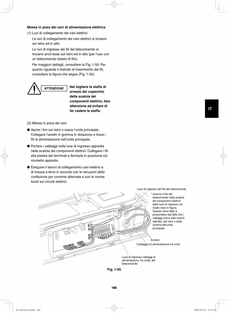
GB
FR
DE
IT
PT
GR
ES
195195
* Inserire il filo del telecomando nella scatola dei componenti elettrici dalla luce di ingresso nel modo visto in figura. Questo viene fatto a prescindere dal fatto che i cablaggi siano stati inseriti dall'alto, dal retro o dalla sinistra dell'unità principale.
Luce di ingresso del filo del telecomando
Cablaggio di alimentazione fra unità
Luce di ingresso cablaggi di alimentazione, fra unità, del telecomando
Arresto
Messa in posa dei cavi di alimentazione elettrica
(1) Luci di collegamento dei cavi elettrici
Le luci di collegamento dei cavi elettrici si trovano sul retro ed in alto.
Le luci di ingresso dei fili del telecomando si trovano anch’esse sul retro ed in alto (per l’uso con un telecomando dotato di filo).
Per maggiori dettagli, consultare la Fig. 1-50. Per quanto riguarda il metodo di inserimento dei fili, consultare la figura che segue (Fig. 1-55).
(2) Messa in posa dei cavi
● Aprire i fori sul retro o sopra l’unità principale. Collegare l’anello in gomma in dotazione e tirare i fili di alimentazione nell’unità principale.
● Portare i cablaggi nella luce di ingresso apposita nella scatola dei componenti elettrici. Collegare i fili alla piastra dei terminali e fermarla in posizione col morsetto apposito.
● Eseguire il lavoro di collegamento cavi elettrici e di messa a terra in accordo con le istruzioni della confezione per corrente alternata e con le norme locali sui circuiti elettrici.
ATTENZIONE Nel togliere la staffa di arresto dal coperchio della scatola dei componenti elettrici, fare attenzione ad evitare di far cadere la staffa.
Fig. 1-55
DC_Inverter_Ita.indd 195DC_Inverter_Ita.indd 195 2007/07/25 12:13:332007/07/25 12:13:33
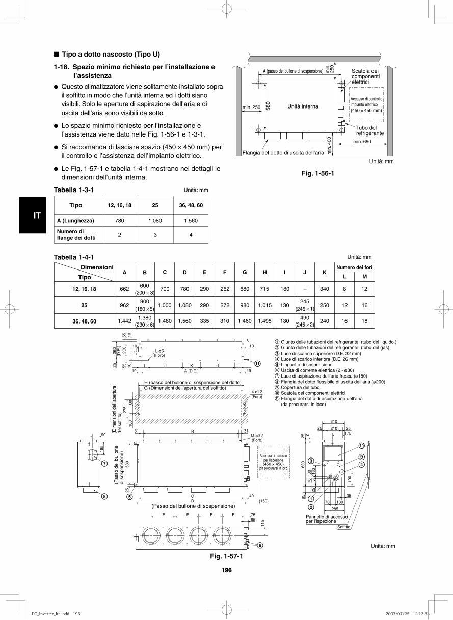
GB
FR
DE
IT
PT
GR
ES
196196
Fig. 1-56-1
Fig. 1-57-1
Unità interna Accesso di controllo impianto elettrico (450 × 450 mm)
Flangia del dotto di uscita dell’aria
min. 250
min
. 400
min. 650
580
A (passo del bullone di sospensione) Scatola dei componenti elettrici
Tubo del refrigerante
min
. 25
0
■ Tipo a dotto nascosto (Tipo U)
1-18. Spazio minimo richiesto per l’installazione e l’assistenza
● Questo climatizzatore viene solitamente installato sopra il soffitto in modo che l’unità interna ed i dotti siano visibili. Solo le aperture di aspirazione dell’aria e di uscita dell’aria sono visibili da sotto.
● Lo spazio minimo richiesto per l’installazione e l’assistenza viene dato nelle Fig. 1-56-1 e 1-3-1.
● Si raccomanda di lasciare spazio (450 × 450 mm) per il controllo e l’assistenza dell’impianto elettrico.
● Le Fig. 1-57-1 e tabella 1-4-1 mostrano nei dettagli le dimensioni dell’unità interna.
Tabella 1-3-1
Tabella 1-4-1
Tipo
A (Lunghezza)
Numero di flange dei dotti
36, 48, 60
1.560
4
25
1.080
3
12, 16, 18
780
2
Dimensioni
Tipo
12, 16, 18
25
36, 48, 60
E F G I J K
662 600
700 780 290 262 680 715 180 – 340 8 1 2 (200 × 3)
962 900
1.000 1.080 290 272 980 1.015 130 245
250 12 16 (180 × 5) (245 × 1)
1.4421.380
1.480 1.560 335 310 1.460 1.495 130 490
240 16 18 (230 × 6) (245 × 2)
Numero dei fori
L M C D B A H
Giunto delle tubazioni del refrigerante (tubo del liquido )Giunto delle tubazioni del refrigerante (tubo del gas)Luce di scarico superiore (D.E. 32 mm) Luce di scarico inferiore (D.E. 26 mm) Linguetta di sospensione Uscita di corrente elettrica (2 - ø30)Luce di aspirazione dell’aria fresca (ø150)Flangia del dotto flessibile di uscita dell’aria (ø200)Copertura del tuboScatola dei componenti elettriciFlangia del dotto di aspirazione dell’aria (da procurarsi in loco)
9
10
9
10
11
11
(Passo del bullone di sospensione)
(Pas
so d
el b
ullo
ne
di s
ospe
nsio
ne)
M-ø3.3(Foro)
4-ø12(Foro)
(Foro)
A (D.E.)
L-ø6
I
10 10
105555
200
10 IJJ K
B
CD (150)
40
E E E F 7565
285
70 130
25 210
310
25175
35
903131
H (passo del bullone di sospensione del dotto)G (Dimensioni dell’apertura del soffitto)
25
100
185
580
25
115
190
85
2570
30 160
630
25 10
8827
5
(Dim
ensi
oni d
ell’a
pert
ura
del s
offit
to)
260
(D.E
.)
1919
Apertura di accesso per l’ispezione (450 × 450)
(da procurarsi in loco)
Pannello di accesso per l’ispezione
Soffitto
Unità: mm
Unità: mm
Unità: mm
Unità: mm
DC_Inverter_Ita.indd 196DC_Inverter_Ita.indd 196 2007/07/25 12:13:332007/07/25 12:13:33
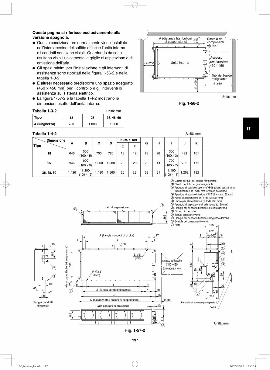
GB
FR
DE
IT
PT
GR
ES
197
Fig. 1-56-2
min.250 580
min
.400
A (distanza tra i bulloni di sospensione) m
in.
250
Unità interna
min.650
Scatola dei componenti elettrici
Accesso per ispezioni450 450
Tubi del liquido refrigerante
Questa pagina si riferisce esclusivamente alla versione spagnola.● Questo condizionatore normalmente viene installato
nell’intercapedine del soffitto affinché l’unità interna e i condotti non siano visibili. Guardando da sotto risultano visibili unicamente le griglie di aspirazione e di emissione dell’aria.
● Gli spazi minimi per l’installazione e gli interventi di assistenza sono riportati nella figura 1-56-2 e nella tabella 1-3-2.
● È altresì necessario predisporre uno spazio adeguato (450 × 450 mm) per il controllo e gli interventi di assistenza sul sistema elettrico.
● La figura 1-57-2 e la tabella 1-4-2 mostrano le dimensioni esatte dell’unità interna.
Tipo
A (lunghezza)
36, 48, 60
1.560
25
1.080
18
780
DimensioneTipo
18
25
36, 48, 60
E F G H I J K
646 500
700 780 18 12 73 96 492 (100 × 5)
946 900
1.000 1.080 26 20 23 41 782 (100 × 9)
1.4261.300
1.480 1.560 26 28 63 81 1.262
161
171
182 (100 × 13)
300 (100 × 3)
700 (100 × 7)
1.100(100 × 11)
C D B A Num. di fori
262
100
580
25
H H I
(dis
tanz
a tra
i bu
lloni
di s
ospe
nsio
ne)
A (flangia condotti di uscita)
Lato di aspirazione
(flangia condotti di uscita) Lato condotti di emissione
J (flangia condotti di uscita)
27
B G G
K 40
C
D (distanza tra i bulloni di sospensione)
75
(150)
115 18
6
65
90
100
43 43
185
186
310
262
31 100p×2=200 31
35
70 130
175
630
31
25
190
285
160
25
30
Accesso per ispezioni(450 450)
(provvedere in loco)
E- 3.1(foro)
F- 3.3(foro)
Pannello di accesso per ispezioni
Soffitto
1
2
3
4
9
10
11
6
5
7
8
12
13
Unità: mm
Unità: mm
Unità: mm
Giunto per tubi del liquido refrigeranteGiunto per tubi del gas refrigeranteApertura di scarico superiore VP25 (diam. est. 32 mm)tubo flessibile da 200 mm fornito in dotazioneApertura di scarico inferiore VP25 (diam. est. 32 mm)Aletta di sospensione (n. 4 da 12 × 37 mm)Uscite per alimentazione (n. 2 da ø30 mm)Apertura di aspirazione di aria nuova (ø150 mm)Flangia per condotto flessibile di uscita dell'ariaCoperchio del tubo
Flangia per condotto flessibile d'ingresso dell'ariaScatola dei componenti elettrici
11 Tenuta pressione vento10
12
Filtro13
Fig. 1-57-2
Tabella 1-4-2
Tabella 1-3-2
Unità: mm
DC_Inverter_Ita.indd 197DC_Inverter_Ita.indd 197 2007/07/25 12:13:332007/07/25 12:13:33
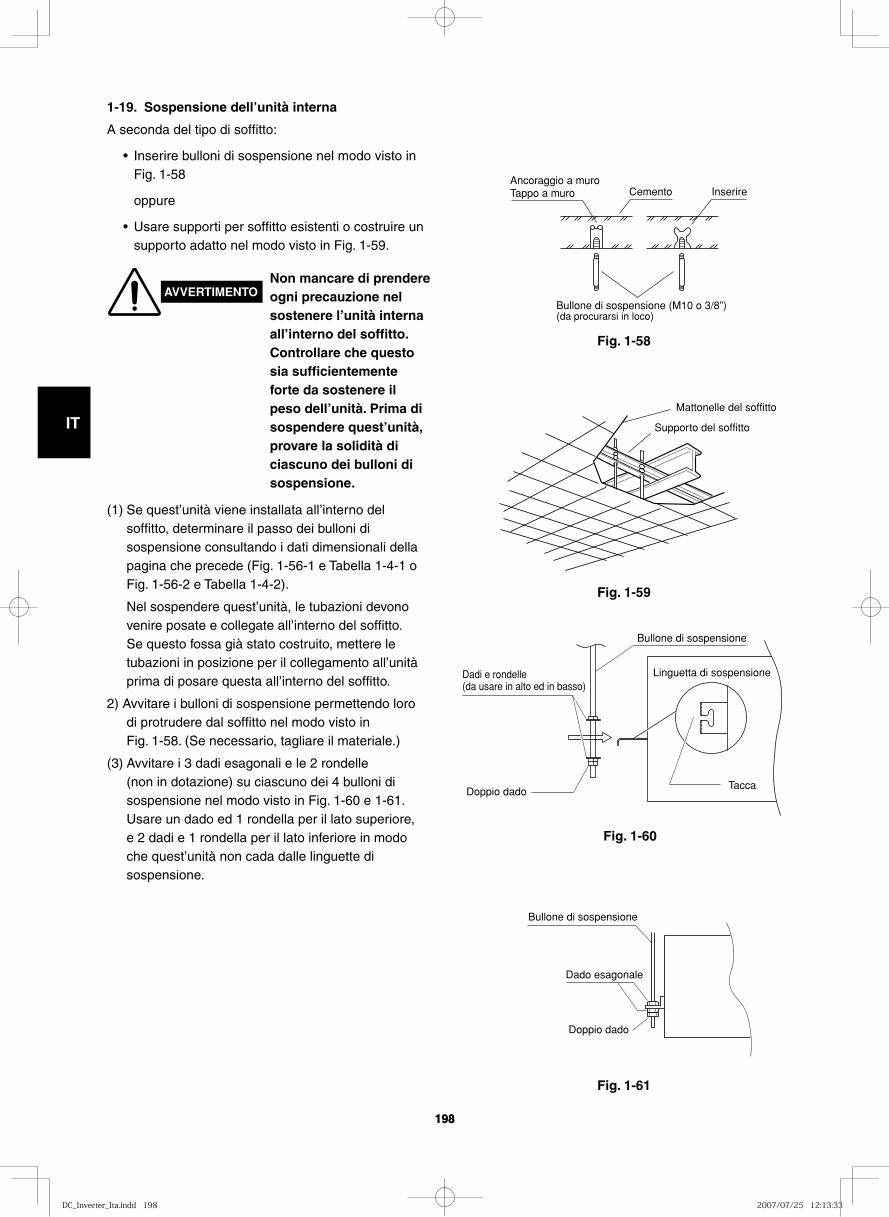
GB
FR
DE
IT
PT
GR
ES
198198
Fig. 1-58
1-19. Sospensione dell’unità interna
A seconda del tipo di soffitto:
• Inserire bulloni di sospensione nel modo visto in Fig. 1-58
oppure
• Usare supporti per soffitto esistenti o costruire un supporto adatto nel modo visto in Fig. 1-59.
Ancoraggio a muroTappo a muro Cemento Inserire
Bullone di sospensione (M10 o 3/8”)(da procurarsi in loco)
Fig. 1-59
Fig. 1-60
Fig. 1-61
Mattonelle del soffitto
Supporto del soffitto
Bullone di sospensione
Linguetta di sospensioneDadi e rondelle (da usare in alto ed in basso)
Doppio dadoTacca
Bullone di sospensione
Dado esagonale
Doppio dado
AVVERTIMENTONon mancare di prendere ogni precauzione nel sostenere l’unità interna all’interno del soffitto. Controllare che questo sia sufficientemente forte da sostenere il peso dell’unità. Prima di sospendere quest’unità, provare la solidità di ciascuno dei bulloni di sospensione.
(1) Se quest’unità viene installata all’interno del soffitto, determinare il passo dei bulloni di sospensione consultando i dati dimensionali della pagina che precede (Fig. 1-56-1 e Tabella 1-4-1 o Fig. 1-56-2 e Tabella 1-4-2).
Nel sospendere quest’unità, le tubazioni devono venire posate e collegate all’interno del soffitto. Se questo fossa già stato costruito, mettere le tubazioni in posizione per il collegamento all’unità prima di posare questa all’interno del soffitto.
2) Avvitare i bulloni di sospensione permettendo loro di protrudere dal soffitto nel modo visto in Fig. 1-58. (Se necessario, tagliare il materiale.)
(3) Avvitare i 3 dadi esagonali e le 2 rondelle (non in dotazione) su ciascuno dei 4 bulloni di sospensione nel modo visto in Fig. 1-60 e 1-61. Usare un dado ed 1 rondella per il lato superiore, e 2 dadi e 1 rondella per il lato inferiore in modo che quest’unità non cada dalle linguette di sospensione.
DC_Inverter_Ita.indd 198DC_Inverter_Ita.indd 198 2007/07/25 12:13:332007/07/25 12:13:33
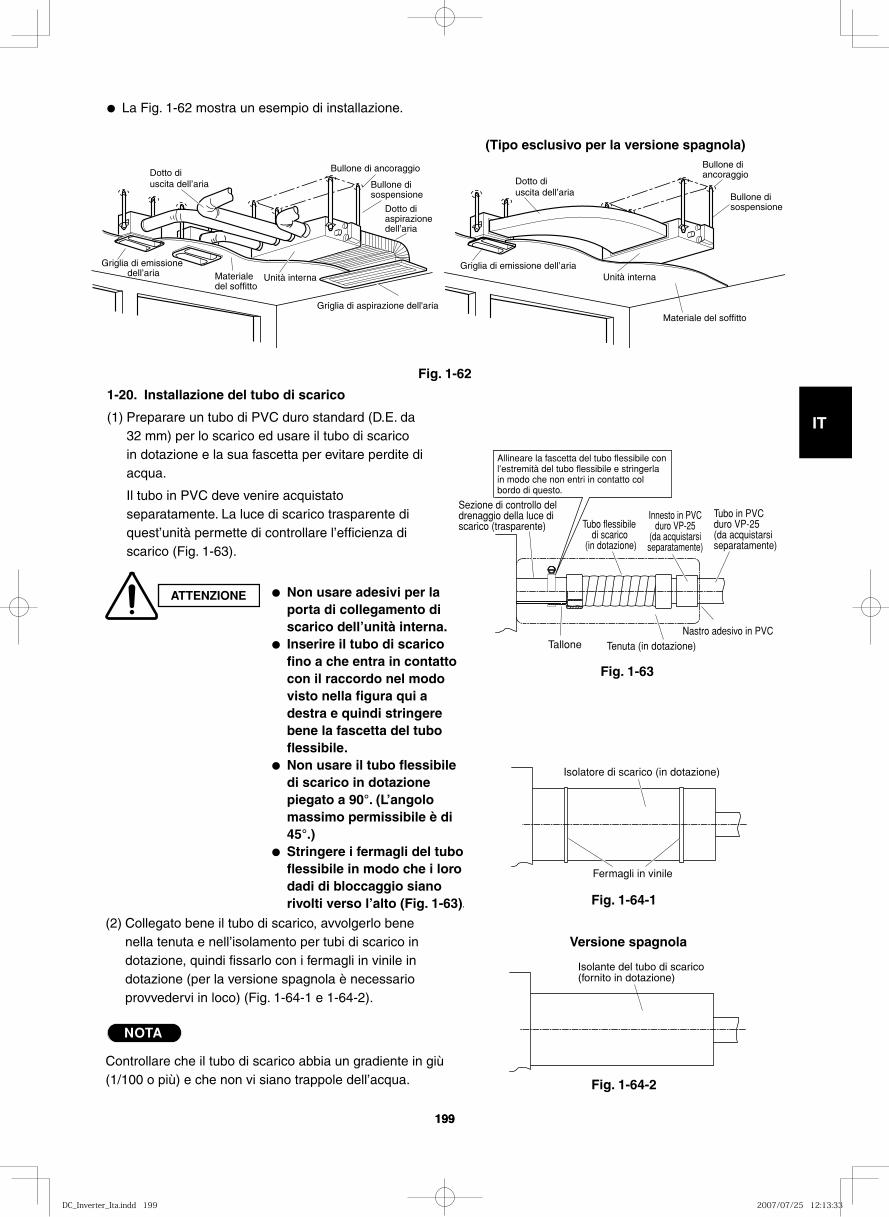
GB
FR
DE
IT
PT
GR
ES
199199
● La Fig. 1-62 mostra un esempio di installazione.
Fig. 1-62
Fig. 1-63
Tubo flessibile di scarico
(in dotazione)
Tenuta (in dotazione)
Allineare la fascetta del tubo flessibile con l’estremità del tubo flessibile e stringerla in modo che non entri in contatto col bordo di questo.
Sezione di controllo del drenaggio della luce di scarico (trasparente)
Innesto in PVC duro VP-25
(da acquistarsi separatamente)
Tubo in PVC duro VP-25 (da acquistarsi separatamente)
Nastro adesivo in PVCTallone
Fermagli in vinile
Isolatore di scarico (in dotazione)
1-20. Installazione del tubo di scarico
(1) Preparare un tubo di PVC duro standard (D.E. da 32 mm) per lo scarico ed usare il tubo di scarico in dotazione e la sua fascetta per evitare perdite di acqua.
Il tubo in PVC deve venire acquistato separatamente. La luce di scarico trasparente di quest’unità permette di controllare l’efficienza di scarico (Fig. 1-63).
ATTENZIONE ● Non usare adesivi per la porta di collegamento di scarico dell’unità interna.
● Inserire il tubo di scarico fino a che entra in contatto con il raccordo nel modo visto nella figura qui a destra e quindi stringere bene la fascetta del tubo flessibile.
● Non usare il tubo flessibile di scarico in dotazione piegato a 90°. (L’angolo massimo permissibile è di 45°.)
● Stringere i fermagli del tubo flessibile in modo che i loro dadi di bloccaggio siano rivolti verso l’alto (Fig. 1-63).
(2) Collegato bene il tubo di scarico, avvolgerlo bene nella tenuta e nell’isolamento per tubi di scarico in dotazione, quindi fissarlo con i fermagli in vinile in dotazione (per la versione spagnola è necessario provvedervi in loco) (Fig. 1-64-1 e 1-64-2).
NOTA
Controllare che il tubo di scarico abbia un gradiente in giù (1/100 o più) e che non vi siano trappole dell’acqua.
Dotto di uscita dell’aria
Bullone di ancoraggio
Bullone di sospensione
Dotto di aspirazione dell’aria
Griglia di aspirazione dell'aria
Unità internaMateriale del soffitto
Griglia di emissione dell’aria
Dotto di uscita dell’aria
Griglia di emissione dell’aria
Materiale del soffitto
Unità interna
Bullone di ancoraggio
Bullone di sospensione
(Tipo esclusivo per la versione spagnola)
Fig. 1-64-2
Isolante del tubo di scarico (fornito in dotazione)
Versione spagnola
Fig. 1-64-1
DC_Inverter_Ita.indd 199DC_Inverter_Ita.indd 199 2007/07/25 12:13:332007/07/25 12:13:33
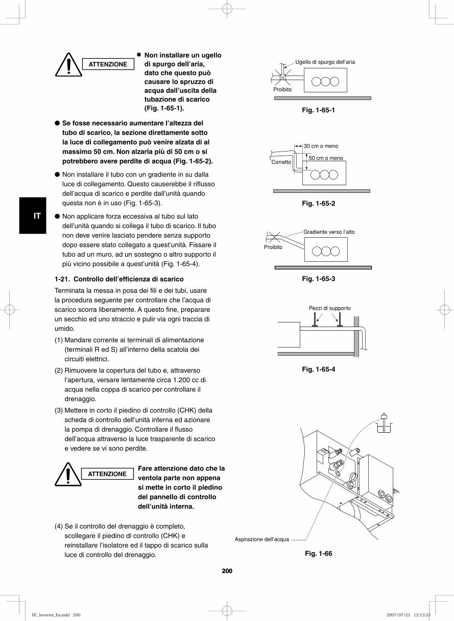
GB
FR
DE
IT
PT
GR
ES
200200
Fig. 1-65-1
Fig. 1-65-2
Fig. 1-65-3
Fig. 1-65-4
Fig. 1-66
Ugello di spurgo dell’aria
Proibito
Corretto
30 cm o meno
50 cm o meno
Proibito
Gradiente verso l’alto
Pezzi di supporto
Aspirazione dell’acqua
● Se fosse necessario aumentare l’altezza del tubo di scarico, la sezione direttamente sotto la luce di collegamento può venire alzata di al massimo 50 cm. Non alzarla più di 50 cm o si potrebbero avere perdite di acqua (Fig. 1-65-2).
● Non installare il tubo con un gradiente in su dalla luce di collegamento. Questo causerebbe il riflusso dell’acqua di scarico e perdite dall’unità quando questa non è in uso (Fig. 1-65-3).
● Non applicare forza eccessiva al tubo sul lato dell’unità quando si collega il tubo di scarico. Il tubo non deve venire lasciato pendere senza supporto dopo essere stato collegato a quest’unità. Fissare il tubo ad un muro, ad un sostegno o altro supporto il più vicino possibile a quest’unità (Fig. 1-65-4).
1-21. Controllo dell’efficienza di scarico
Terminata la messa in posa dei fili e dei tubi, usare la procedura seguente per controllare che l’acqua di scarico scorra liberamente. A questo fine, preparare un secchio ed uno straccio e pulir via ogni traccia di umido.
(1) Mandare corrente ai terminali di alimentazione (terminali R ed S) all’interno della scatola dei circuiti elettrici.
(2) Rimuovere la copertura del tubo e, attraverso l’apertura, versare lentamente circa 1.200 cc di acqua nella coppa di scarico per controllare il drenaggio.
(3) Mettere in corto il piedino di controllo (CHK) della scheda di controllo dell’unità interna ed azionare la pompa di drenaggio. Controllare il flusso dell’acqua attraverso la luce trasparente di scarico e vedere se vi sono perdite.
(4) Se il controllo del drenaggio è completo, scollegare il piedino di controllo (CHK) e reinstallare l’isolatore ed il tappo di scarico sulla luce di controllo del drenaggio.
ATTENZIONE
● Non installare un ugello di spurgo dell’aria, dato che questo può causare lo spruzzo di acqua dall’uscita della tubazione di scarico (Fig. 1-65-1).
ATTENZIONEFare attenzione dato che la ventola parte non appena si mette in corto il piedino del pannello di controllo dell’unità interna.
DC_Inverter_Ita.indd 200DC_Inverter_Ita.indd 200 2007/07/25 12:13:332007/07/25 12:13:33
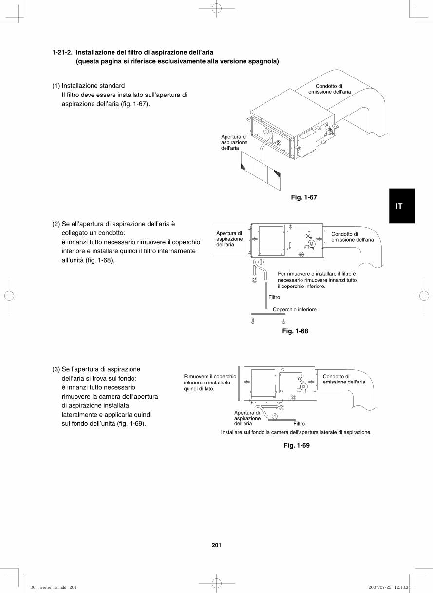
GB
FR
DE
IT
PT
GR
ES
201
(1) Installazione standardIl filtro deve essere installato sull’apertura di aspirazione dell’aria (fig. 1-67).
(2) Se all’apertura di aspirazione dell’aria è collegato un condotto:è innanzi tutto necessario rimuovere il coperchio inferiore e installare quindi il filtro internamente all’unità (fig. 1-68).
(3) Se l’apertura di aspirazione dell’aria si trova sul fondo:è innanzi tutto necessario rimuovere la camera dell’apertura di aspirazione installata lateralmente e applicarla quindi sul fondo dell’unità (fig. 1-69).
Condotto di emissione dell'aria
Apertura di aspirazione dell'aria
2
1
Condotto di emissione dell'aria
Apertura di aspirazione dell'aria
2
1
Per rimuovere o installare il filtro è necessario rimuovere innanzi tutto il coperchio inferiore.
Filtro
Coperchio inferiore
Condotto di emissione dell'aria
Apertura di aspirazione dell'aria
2
1
Installare sul fondo la camera dell'apertura laterale di aspirazione.
Filtro
Rimuovere il coperchio inferiore e installarlo quindi di lato.
Fig. 1-67
Fig. 1-68
Fig. 1-69
1-21-2. Installazione del filtro di aspirazione dell’aria (questa pagina si riferisce esclusivamente alla versione spagnola)
DC_Inverter_Ita.indd 201DC_Inverter_Ita.indd 201 2007/07/25 12:13:342007/07/25 12:13:34
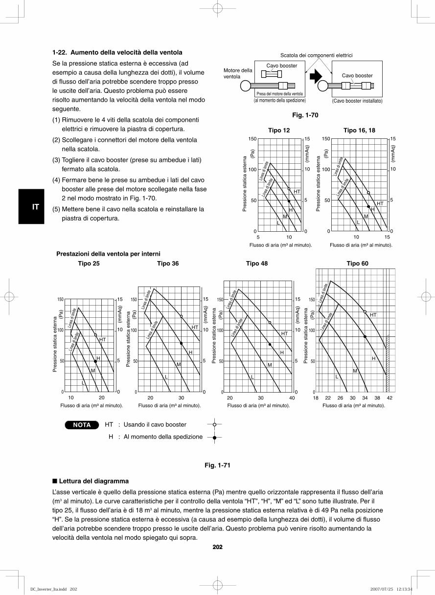
GB
FR
DE
IT
PT
GR
ES
202202
5
Flusso di aria (m³ al minuto). Flusso di aria (m³ al minuto). P
ress
ione
sta
tica
este
rna
0
50
100
0
5
10
15 150
10
(mm
Aq)
(Pa)
HT
H M
L
20
Flusso di aria (m³ al minuto). Flusso di aria (m³ al minuto). Flusso di aria (m³ al minuto). Flusso di aria (m³ al minuto).
Pre
ssio
ne s
tatic
a es
tern
a
0
50
0
5
10
15 150
10
HT
H
L
100
M
(mm
Aq)
(Pa)
30 40 18 22 26 30 34 38 42
Pre
ssio
ne s
tatic
a es
tern
a
0
50
0
5
10
15 150
20
L
100
M
H
M
H
L
(mm
Aq)
(Pa)
Pre
ssio
ne s
tatic
a es
tern
a
0
50
150
100
(Pa)
HT
HT
30
Pre
ssio
ne s
tatic
a es
tern
a
0
50
0
5
10
15 150
20
HT
L
100
M
H
(mm
Aq)
(Pa)
15
Pre
ssio
ne s
tatic
a es
tern
a
0
50
0
5
10
15 150
10
HT
M L
100
H
(mm
Aq)
(Pa)
Tipo 16, 18Tipo 12
Prestazioni della ventola per interni
Tipo 25 Tipo 36 Tipo 48 Tipo 60Lin
ea d
i lim
iteLin
ea di
limite
Linea
di li
mite
Linea
di lim
ite
Linea
di li
mite
Linea
di li
mite
Linea
di li
mite
Linea
di lim
ite
Linea
di lim
iteLin
ea di
limite
Linea
di li
mite
Linea
di lim
ite
HT : Usando il cavo booster
H : Al momento della spedizione
NOTA
1-22. Aumento della velocità della ventola
Se la pressione statica esterna è eccessiva (ad esempio a causa della lunghezza dei dotti), il volume di flusso dell’aria potrebbe scendere troppo presso le uscite dell’aria. Questo problema può essere risolto aumentando la velocità della ventola nel modo seguente.
(1) Rimuovere le 4 viti della scatola dei componenti elettrici e rimuovere la piastra di copertura.
(2) Scollegare i connettori del motore della ventola nella scatola.
(3) Togliere il cavo booster (prese su ambedue i lati) fermato alla scatola.
(4) Fermare bene le prese su ambedue i lati del cavo booster alle prese del motore scollegate nella fase 2 nel modo mostrato in Fig. 1-70.
(5) Mettere bene il cavo nella scatola e reinstallare la piastra di copertura.
Fig. 1-70
Fig. 1-71
Cavo booster
Cavo booster
Scatola dei componenti elettrici
(al momento della spedizione) (Cavo booster installato)Presa del motore della ventola
Motore della ventola
■ Lettura del diagramma
L’asse verticale è quello della pressione statica esterna (Pa) mentre quello orizzontale rappresenta il flusso dell’aria (m3 al minuto). Le curve caratteristiche per il controllo della ventola “HT”, “H”, “M” ed “L” sono tutte illustrate. Per il tipo 25, il flusso dell’aria è di 18 m3 al minuto, mentre la pressione statica esterna relativa è di 49 Pa nella posizione “H”. Se la pressione statica esterna è eccessiva (a causa ad esempio della lunghezza dei dotti), il volume di flusso dell’aria potrebbe scendere troppo presso le uscite dell’aria. Questo problema può venire risolto aumentando la velocità della ventola nel modo spiegato qui sopra.
DC_Inverter_Ita.indd 202DC_Inverter_Ita.indd 202 2007/07/25 12:13:342007/07/25 12:13:34
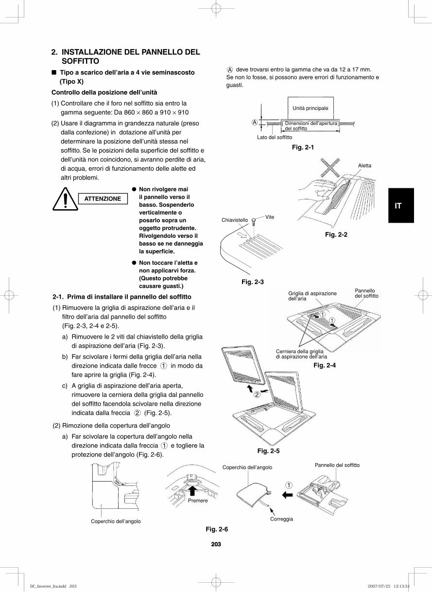
GB
FR
DE
IT
PT
GR
ES
203203
2. INSTALLAZIONE DEL PANNELLO DEL SOFFITTO
■ Tipo a scarico dell’aria a 4 vie seminascosto (Tipo X)
Controllo della posizione dell’unità
(1) Controllare che il foro nel soffitto sia entro la gamma seguente: Da 860 × 860 a 910 × 910
(2) Usare il diagramma in grandezza naturale (preso dalla confezione) in dotazione all’unità per determinare la posizione dell’unità stessa nel soffitto. Se le posizioni della superficie del soffitto e dell’unità non coincidono, si avranno perdite di aria, di acqua, errori di funzionamento delle alette ed altri problemi.
ATTENZIONE
● Non rivolgere mai il pannello verso il basso. Sospenderlo verticalmente o posarlo sopra un oggetto protrudente. Rivolgendolo verso il basso se ne danneggia la superficie.
● Non toccare l’aletta e non applicarvi forza. (Questo potrebbe causare guasti.)
A deve trovarsi entro la gamma che va da 12 a 17 mm. Se non lo fosse, si possono avere errori di funzionamento e guasti.
Lato del soffitto
Unità principale
Dimensioni dell’apertura del soffitto
A
Fig. 2-1
Aletta
Fig. 2-2
Fig. 2-3
2
Fig. 2-5
2-1. Prima di installare il pannello del soffitto
(1) Rimuovere la griglia di aspirazione dell’aria e il filtro dell’aria dal pannello del soffitto (Fig. 2-3, 2-4 e 2-5).
a) Rimuovere le 2 viti dal chiavistello della griglia di aspirazione dell’aria (Fig. 2-3).
b) Far scivolare i fermi della griglia dell’aria nella direzione indicata dalle frecce 1 in modo da fare aprire la griglia (Fig. 2-4).
c) A griglia di aspirazione dell’aria aperta, rimuovere la cerniera della griglia dal pannello del soffitto facendola scivolare nella direzione indicata dalla freccia 2 (Fig. 2-5).
(2) Rimozione della copertura dell’angolo
a) Far scivolare la copertura dell’angolo nella direzione indicata dalla freccia 1 e togliere la protezione dell’angolo (Fig. 2-6).
Coperchio dell’angolo
Pannello del soffitto
Correggia
Premere
1
Coperchio dell’angolo
Fig. 2-6
ChiavistelloVite
Griglia di aspirazione dell’aria
Pannello del soffitto
Cerniera della griglia di aspirazione dell’aria
11
Fig. 2-4
DC_Inverter_Ita.indd 203DC_Inverter_Ita.indd 203 2007/07/25 12:13:342007/07/25 12:13:34
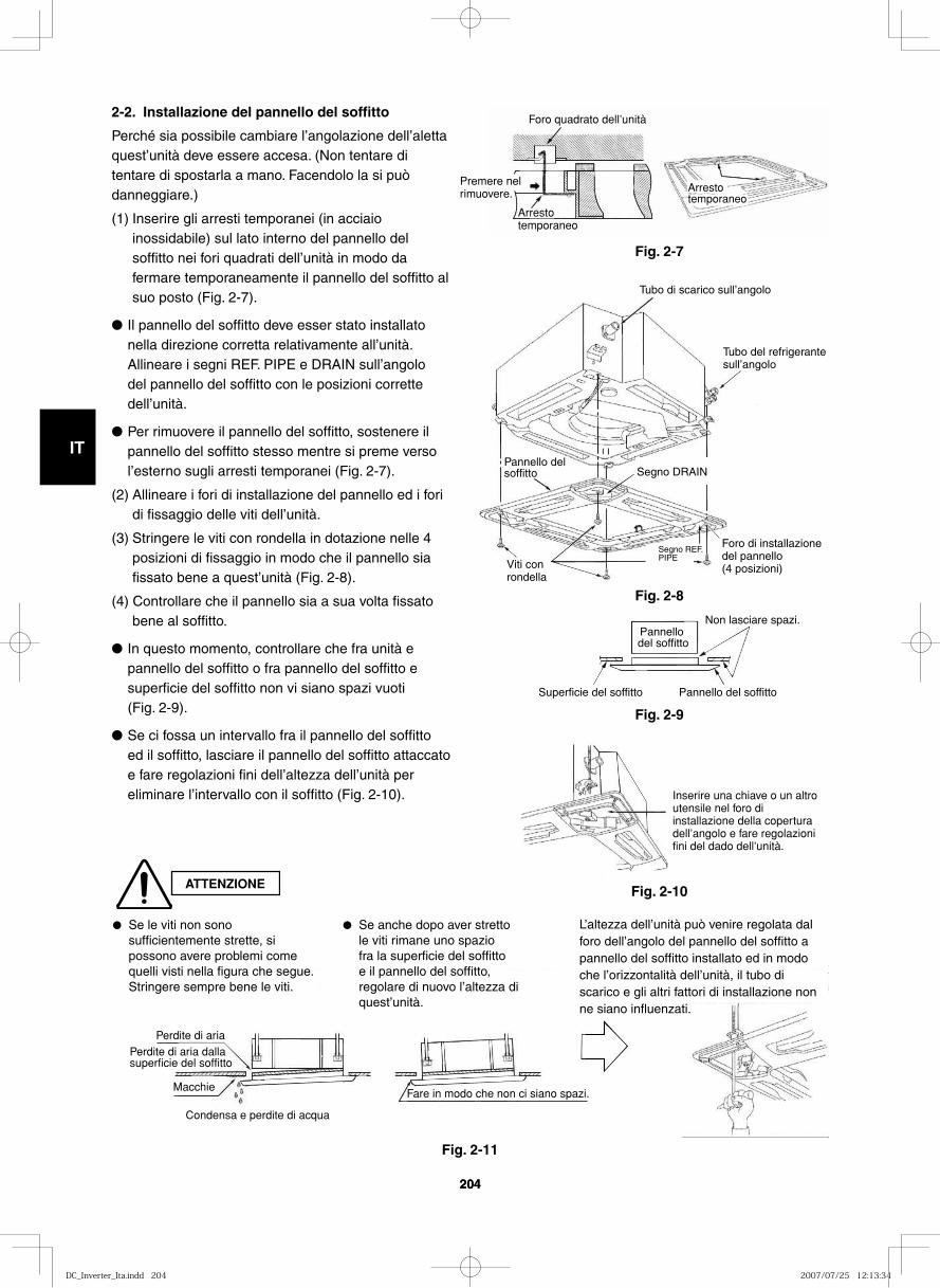
GB
FR
DE
IT
PT
GR
ES
204204
ATTENZIONE
2-2. Installazione del pannello del soffitto
Perché sia possibile cambiare l’angolazione dell’aletta quest’unità deve essere accesa. (Non tentare di tentare di spostarla a mano. Facendolo la si può danneggiare.)
(1) Inserire gli arresti temporanei (in acciaio inossidabile) sul lato interno del pannello del soffitto nei fori quadrati dell’unità in modo da fermare temporaneamente il pannello del soffitto al suo posto (Fig. 2-7).
● Il pannello del soffitto deve esser stato installato nella direzione corretta relativamente all’unità. Allineare i segni REF. PIPE e DRAIN sull’angolo del pannello del soffitto con le posizioni corrette dell’unità.
● Per rimuovere il pannello del soffitto, sostenere il pannello del soffitto stesso mentre si preme verso l’esterno sugli arresti temporanei (Fig. 2-7).
(2) Allineare i fori di installazione del pannello ed i fori di fissaggio delle viti dell’unità.
(3) Stringere le viti con rondella in dotazione nelle 4 posizioni di fissaggio in modo che il pannello sia fissato bene a quest’unità (Fig. 2-8).
(4) Controllare che il pannello sia a sua volta fissato bene al soffitto.
● In questo momento, controllare che fra unità e pannello del soffitto o fra pannello del soffitto e superficie del soffitto non vi siano spazi vuoti (Fig. 2-9).
● Se ci fossa un intervallo fra il pannello del soffitto ed il soffitto, lasciare il pannello del soffitto attaccato e fare regolazioni fini dell’altezza dell’unità per eliminare l’intervallo con il soffitto (Fig. 2-10).
Foro quadrato dell’unità
Arresto temporaneo
Premere nel rimuovere. Arresto
temporaneo
Fig. 2-7
Tubo del refrigerante sull’angolo
Tubo di scarico sull’angolo
Segno DRAINPannello del soffitto
Viti con rondella
Segno REF. PIPE
Foro di installazione del pannello (4 posizioni)
Fig. 2-8
Non lasciare spazi.
Pannello del soffitto
Pannello del soffitto
Superficie del soffitto
Fig. 2-9
Inserire una chiave o un altro utensile nel foro di installazione della copertura dell’angolo e fare regolazioni fini del dado dell’unità.
Perdite di ariaPerdite di aria dalla superficie del soffitto
Macchie
Condensa e perdite di acqua
Fare in modo che non ci siano spazi.
Fig. 2-10
Fig. 2-11
● Se le viti non sono sufficientemente strette, si possono avere problemi come quelli visti nella figura che segue. Stringere sempre bene le viti.
● Se anche dopo aver stretto le viti rimane uno spazio fra la superficie del soffitto e il pannello del soffitto, regolare di nuovo l’altezza di quest’unità.
L’altezza dell’unità può venire regolata dal foro dell’angolo del pannello del soffitto a pannello del soffitto installato ed in modo che l’orizzontalità dell’unità, il tubo di scarico e gli altri fattori di installazione non ne siano influenzati.
DC_Inverter_Ita.indd 204DC_Inverter_Ita.indd 204 2007/07/25 12:13:342007/07/25 12:13:34
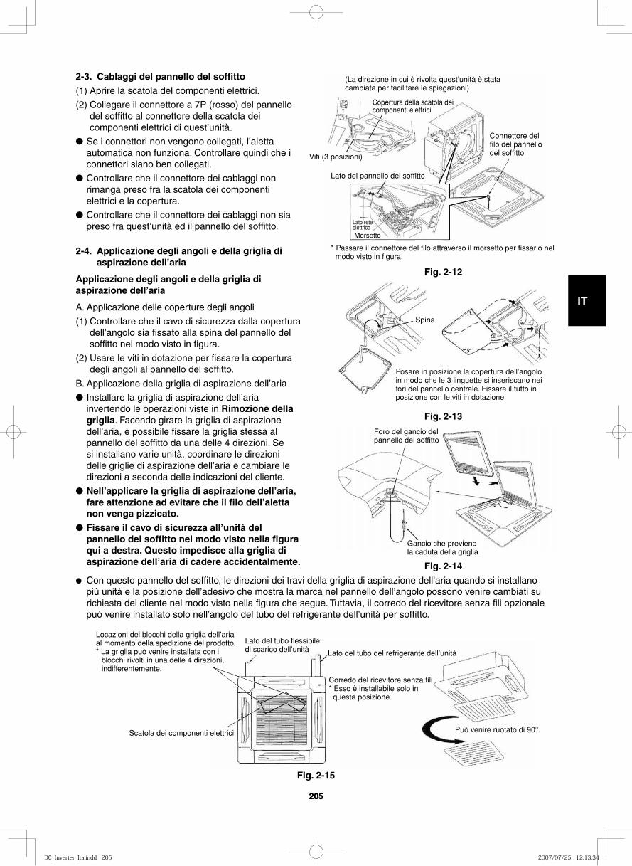
GB
FR
DE
IT
PT
GR
ES
205205
2-3. Cablaggi del pannello del soffitto (1) Aprire la scatola del componenti elettrici.
(2) Collegare il connettore a 7P (rosso) del pannello del soffitto al connettore della scatola dei componenti elettrici di quest’unità.
● Se i connettori non vengono collegati, l’aletta automatica non funziona. Controllare quindi che i connettori siano ben collegati.
● Controllare che il connettore dei cablaggi non rimanga preso fra la scatola dei componenti elettrici e la copertura.
● Controllare che il connettore dei cablaggi non sia preso fra quest’unità ed il pannello del soffitto.
2-4. Applicazione degli angoli e della griglia di aspirazione dell’aria
Applicazione degli angoli e della griglia di aspirazione dell’aria
A. Applicazione delle coperture degli angoli
(1) Controllare che il cavo di sicurezza dalla copertura dell’angolo sia fissato alla spina del pannello del soffitto nel modo visto in figura.
(2) Usare le viti in dotazione per fissare la copertura degli angoli al pannello del soffitto.
B. Applicazione della griglia di aspirazione dell’aria
● Installare la griglia di aspirazione dell’aria invertendo le operazioni viste in Rimozione della griglia. Facendo girare la griglia di aspirazione dell’aria, è possibile fissare la griglia stessa al pannello del soffitto da una delle 4 direzioni. Se si installano varie unità, coordinare le direzioni delle griglie di aspirazione dell’aria e cambiare le direzioni a seconda delle indicazioni del cliente.
● Nell’applicare la griglia di aspirazione dell’aria, fare attenzione ad evitare che il filo dell’aletta non venga pizzicato.
● Fissare il cavo di sicurezza all’unità del pannello del soffitto nel modo visto nella figura qui a destra. Questo impedisce alla griglia di aspirazione dell’aria di cadere accidentalmente.
(La direzione in cui è rivolta quest’unità è stata cambiata per facilitare le spiegazioni)
Connettore del filo del pannello del soffitto
Lato del pannello del soffitto
Viti (3 posizioni)
Lato rete elettricaMorsetto
Copertura della scatola dei componenti elettrici
* Passare il connettore del filo attraverso il morsetto per fissarlo nel modo visto in figura.
Posare in posizione la copertura dell’angolo in modo che le 3 linguette si inseriscano nei fori del pannello centrale. Fissare il tutto in posizione con le viti in dotazione.
Spina
● Con questo pannello del soffitto, le direzioni dei travi della griglia di aspirazione dell’aria quando si installano più unità e la posizione dell’adesivo che mostra la marca nel pannello dell’angolo possono venire cambiati su richiesta del cliente nel modo visto nella figura che segue. Tuttavia, il corredo del ricevitore senza fili opzionale può venire installato solo nell’angolo del tubo del refrigerante dell’unità per soffitto.
Scatola dei componenti elettrici
Lato del tubo flessibile di scarico dell’unità Lato del tubo del refrigerante dell’unità
Corredo del ricevitore senza fili * Esso è installabile solo in questa posizione.
Può venire ruotato di 90°.
Locazioni dei blocchi della griglia dell’aria al momento della spedizione del prodotto.* La griglia può venire installata con i
blocchi rivolti in una delle 4 direzioni, indifferentemente.
Fig. 2-12
Fig. 2-13
Foro del gancio del pannello del soffitto
Gancio che previene la caduta della griglia
Fig. 2-14
Fig. 2-15
DC_Inverter_Ita.indd 205DC_Inverter_Ita.indd 205 2007/07/25 12:13:342007/07/25 12:13:34
GB
FR
DE
IT
PT
GR
ES
206206
2-5. Controlli dopo l’installazione
● Controllare che non ci siano intervalli fra quest’unità ed il pannello del soffitto o fra il pannello del soffitto e la superficie del soffitto. Gli intervalli possono causare perdite di acqua e condensa.
● Controllare che i cablaggi siano collegati correttamente. Se non lo sono, l’aletta automatica non funzionerà correttamente. (L’indicazione “P09” viene allora visualizzata nel telecomando.) Si possono inoltre avere perdite di acqua e formazione di condensa.
2-6. Per rimuovere il pannello del soffitto e fare riparazioni
Per rimuovere il pannello del soffitto e fare riparazioni, rimuovere la griglia di aspirazione dell’aria ed il filtro dell’aria, quindi scollegare il connettore dei cablaggi all’interno della scatola dei componenti elettrici ed infine togliere le 4 viti di installazione.
2-7. Regolazione dell’aletta automatica
L’aletta di direzione dell’aria dell’uscita del pannello del soffitto può venire regolata nel modo seguente:
● Regolare l’angolazione dell’aletta come desiderato col telecomando. Essa possiede anche una funzione automatica di mozione dell’aria.
NOTA
● Non tentare mai di spostare l’aletta a mano.
● Il flusso corretto dell’aria dipende dalla locazione del climatizzatore, dalla disposizione della stanza e da quella dei mobili. Se il raffrescamento o il riscaldamento sembrano inadeguati, provare a cambiare la direzione del flusso dell’aria.
DC_Inverter_Ita.indd 206DC_Inverter_Ita.indd 206 2007/07/25 12:13:342007/07/25 12:13:34
GB
FR
DE
IT
PT
GR
ES
207207
IMPOR TAN TE! Quei ra ler antes de colo car a uni da de em fun cio na men toEste sis te ma de ar con di cio na do satis faz padrõ es rigo ro sos sobre segu ran ça e fun cio na men to. Na sua capa ci da de de ins ta la dor ou enca rre ga do do ser vi ço, épar te impor tan te do seu tra bal ho ins ta lar ou pres tar ser vi ço ao sis te ma por forma que este fun cio ne segu ra e efi caz men te.
Para ins ta la ção e fun cio na men to sem pro ble mas, deve:● Ler cui da do sa men te este livro de ins tru çõ es antes de come çar.● Seguir cada fase da ins ta la ção ou repa ra ção exac ta men te con-
for me indi ca do.● Obser var todas as nor mas locais, gover na men tais e nacio nais
sobre elec tri ci da de.● Este produto é designado para uso profissional. É necessária
permissão da companhia elétrica ao instalar uma unidade externa que seja conectada a uma rede de distribuição 16 A.
● Pres tar gran de aten ção a todos os avi sos de adver tên cia e pre-cau ção fei tas neste manual.
Este sím bo lo refe re-se a um peri go ou uma norma de tra bal ho de pouca segu ran ça que pode pro vo car um aci den te pes so al grave ou morte.
Este sím bo lo refe re-se a um peri go ou uma norma de tra bal ho de pouca segu ran ça que pode resul tar em aci den te pes so al ou danos em bens ou pro du tos.
Se for neces sá rio, peça ajudaEstas ins tru çõ es são tudo o que é neces sá rio para a maio ria dos locais de ins ta la ção e con di çõ es de manu ten ção. Se pre ci sar de ajuda para um pro ble ma espe cial, quei ra con tac tar o nosso ponto de ven das/ser vi ço ou o dis tri bui dor cer ti fi ca do para obter ins tru çõ es adi cio nais.
No caso de ins ta la ção inco rrec taO fabri can te não será por forma algu ma res pon sá vel pela ins ta la ção inco rrec ta ou ser vi ço de manu ten ção defi cien te, incluin do a falta de cum pri men to das ins tru çõ es apre sen ta das neste docu men to.
PRE CAU ÇÕ ES ESPE CIAIS
ADVERTÊNCIA Ao fazer a ins ta la ção eléc tri ca
O CHO QUE ELÉC TRI CO PODE PRO VO CAR UM ACI DEN TE PES SO AL GRAVE OU MORTE. SÓ UM ELEC TRI CIS TA QUA LI FI CA DO E EXPE RIEN TE DEVE TEN TAR FAZER A INS TA LA ÇÃO ELÉC TRI CA DESTE SIS TE MA.
• Não for ne ça ener gia à uni da de antes de toda a ins ta la ção eléc-tri ca e colo ca ção de tubos esta rem con clu í das ou nova men te liga das e veri fi ca das.
• São usa das ten sõ es eléc tri cas alta men te peri go sas neste sis te ma. Con sul te cui da do sa men te o dia gra ma da ins ta la ção eléc tri ca e estas ins tru çõ es ao fazer a ins ta la ção. Liga çõ es inco-rrec tas e liga ção inade qua da à terra pode cau sar um aci den te pes so al ou morte.
• Ligue a uni da de à terra seguin do as nor mas locais sobre elec-tri ci da de.
• Faça todas liga çõ es eléc tri cas bem aper ta das. Fios eléc tri cos frou xos podem cau sar sobre a que ci men to nos pon tos de liga ção e um pos sí vel peri go de incên dio.
Duran te o Trans por te
Tome cui da do quan do levan tar e des lo car as uni da des para uso no inte rior e no exte rior. Peça ajuda a um par cei ro, e dobre os joel hos ao levan tar a emba la gem para redu zir o esfor ço nas suas cos tas. Rebor dos agu ça dos ou alhe tas de alu mí nio finas na uni da de de ar con di cio na do podem cor tar os seus dedos.
Duran te a Ins ta la ção…
…Numa salaIsole devi da men te qual quer tuba gem que fique ins ta la da den tro duma sala para evi tar “a transpiração” que pode cau sar gote jo e água que irá dani fi car pare des e pisos.
…Em locais húmi dos ou irre gu la resUse uma placa de betão ele va da ou blo cos de betão para obter um ali cer ce maci ço e nive la do para a colo ca ção da uni da de no exte rior. Isto evita danos cau sa dos pela água e vibra ção anor mal.
…Numa área sujei ta a vento forteFixe com fir me za a uni da de para mon ta gem no exte rior com para-fu sos e uma arma ção de metal. Monte um amor te ce dor apro pria-do do ar.
…Numa área sujei ta a neve (para sis te mas do tipo bomba de aque ci men to)
Ins ta le a uni da de para mon ta gem no exte rior numa pla ta for ma ele va da que seja mais alta do que a neve em movi men to. Monte ven ti la do res para a neve.
Ao fazer a liga ção de tuba gens de refri ge ran te
• Ventile bem o ambiente para a eventualidade de uma fuga do gás refrigerante durante a instalação. Tome cuidado para não permitir o contato do gás refrigerante com uma flama, pois isso causa a geração de gás tóxico.
• Mantenha toda a tubulação o mais curta possível.• Use um méto do de dila ta ção para ligar a tuba gem.• Apli que o lubri fi can te do refri ge ran te às super fí cies aca sa la das
da área dila ta da e dos tubos de união antes de os ligar, depois aper te a porca com uma chave dina mó me tro para obter uma liga ção sem fugas.
• Veri fi que cui da do sa men te se exis tem fugas antes de ini ciar o fun cio na men to de ensaio.
Ao rea li zar o ser vi ço
• DES LI GUE a uni da de na caixa prin ci pal de ali men ta çäo eléc tri ca antes de abrir a uni da de para veri fi car ou repa rar peças e a ins ta la ção eléc tri ca.
• Man ten ha os seus dedos e o seu ves tuá rio afas ta dos de peças em movi men to.
• Limpe o local depois de ter aca ba do o tra bal ho, não se esque cen do de veri fi car se não foram dei xa dos den tro da uni da de que está a ser objec to de ser vi ço quais quer peda ços de suca ta ou res tos de fios eléc tri cos.
• Ventile todos os recin tos fecha dos ao ins ta lar ou tes tar o sis te ma de refri ge ra ção. O gás refri ge ran te, caso esca pe e entre em con tac to com fogo ou alta tem pe ra tu ra, pode pro du zir gás tóxi co.
• Após a instalação, certifique-se de que não haja vazamento do gás refrigerante. Se o gás entrar em contato com um fogão aceso, aquecedor de água a gás, aquecedor elétrico de ambiente ou outra fonte de calor, ele
pode causar a geração de gás tóxico.
ADVERTÊNCIA
PRECAUÇÃO
PRECAUÇÃO
DC_Inverter_Por.indd 207DC_Inverter_Por.indd 207 2007/07/25 12:20:112007/07/25 12:20:11
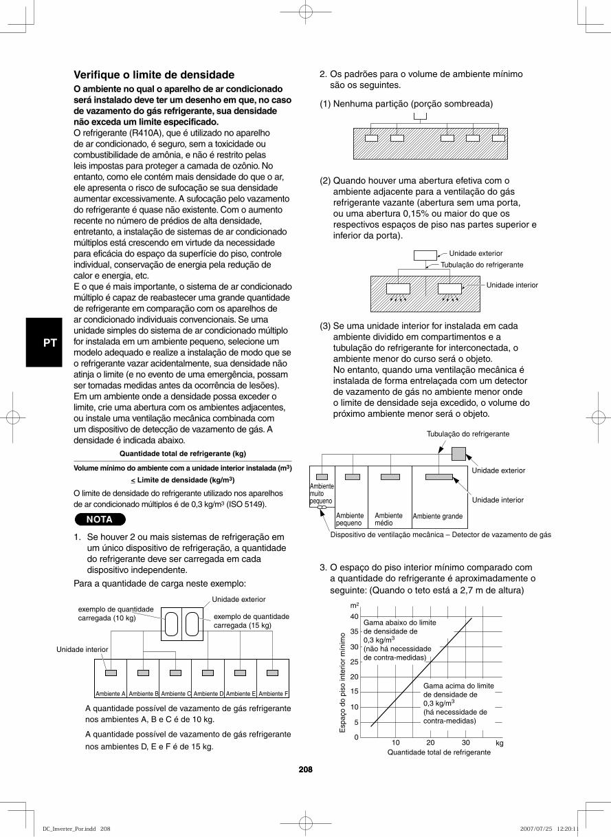
GB
FR
DE
IT
PT
GR
ES
208208
2. Os padrões para o volume de ambiente mínimo são os seguintes.
(1) Nenhuma partição (porção sombreada)
(2) Quando houver uma abertura efetiva com o ambiente adjacente para a ventilação do gás refrigerante vazante (abertura sem uma porta, ou uma abertura 0,15% ou maior do que os respectivos espaços de piso nas partes superior e inferior da porta).
(3) Se uma unidade interior for instalada em cada ambiente dividido em compartimentos e a tubulação do refrigerante for interconectada, o ambiente menor do curso será o objeto.No entanto, quando uma ventilação mecânica é instalada de forma entrelaçada com um detector de vazamento de gás no ambiente menor onde o limite de densidade seja excedido, o volume do próximo ambiente menor será o objeto.
3. O espaço do piso interior mínimo comparado com a quantidade do refrigerante é aproximadamente o seguinte: (Quando o teto está a 2,7 m de altura)
Verifique o limite de densidadeO ambiente no qual o aparelho de ar condicionado será instalado deve ter um desenho em que, no caso de vazamento do gás refrigerante, sua densidade não exceda um limite especificado.O refrigerante (R410A), que é utilizado no aparelho de ar condicionado, é seguro, sem a toxicidade ou combustibilidade de amônia, e não é restrito pelas leis impostas para proteger a camada de ozônio. No entanto, como ele contém mais densidade do que o ar, ele apresenta o risco de sufocação se sua densidade aumentar excessivamente. A sufocação pelo vazamento do refrigerante é quase não existente. Com o aumento recente no número de prédios de alta densidade, entretanto, a instalação de sistemas de ar condicionado múltiplos está crescendo em virtude da necessidade para eficácia do espaço da superfície do piso, controle individual, conservação de energia pela redução de calor e energia, etc.E o que é mais importante, o sistema de ar condicionado múltiplo é capaz de reabastecer uma grande quantidade de refrigerante em comparação com os aparelhos de ar condicionado individuais convencionais. Se uma unidade simples do sistema de ar condicionado múltiplo for instalada em um ambiente pequeno, selecione um modelo adequado e realize a instalação de modo que se o refrigerante vazar acidentalmente, sua densidade não atinja o limite (e no evento de uma emergência, possam ser tomadas medidas antes da ocorrência de lesões).Em um ambiente onde a densidade possa exceder o limite, crie uma abertura com os ambientes adjacentes, ou instale uma ventilação mecânica combinada com um dispositivo de detecção de vazamento de gás. A densidade é indicada abaixo.
Quantidade total de refrigerante (kg)
Volume mínimo do ambiente com a unidade interior instalada (m3)
< Limite de densidade (kg/m3)
O limite de densidade do refrigerante utilizado nos aparelhos de ar condicionado múltiplos é de 0,3 kg/m3 (ISO 5149).
NOTA
1. Se houver 2 ou mais sistemas de refrigeração em um único dispositivo de refrigeração, a quantidade do refrigerante deve ser carregada em cada dispositivo independente.
Para a quantidade de carga neste exemplo:
A quantidade possível de vazamento de gás refrigerante nos ambientes A, B e C é de 10 kg.
A quantidade possível de vazamento de gás refrigerante
nos ambientes D, E e F é de 15 kg.
Unidade exterior
Tubulação do refrigerante
Unidade interior
40
35
30
25
20
15
10
5
0 10 20 30
Quantidade total de refrigerante
Esp
aço
do p
iso
inte
rior
mín
imo
m 2
kg
Gama abaixo do limite de densidade de 0,3 kg/m3 (não há necessidade de contra-medidas)
Gama acima do limite de densidade de 0,3 kg/m3
(há necessidade de contra-medidas)
exemplo de quantidade carregada (10 kg)
Unidade exterior
Unidade interior
Ambiente A Ambiente B Ambiente C Ambiente D Ambiente E Ambiente F
exemplo de quantidade carregada (15 kg)
Tubulação do refrigerante
Unidade exterior
Ambiente muito pequeno Unidade interior
Ambiente pequeno
Ambiente médio
Ambiente grande
Dispositivo de ventilação mecânica – Detector de vazamento de gás
DC_Inverter_Por.indd 208DC_Inverter_Por.indd 208 2007/07/25 12:20:112007/07/25 12:20:11
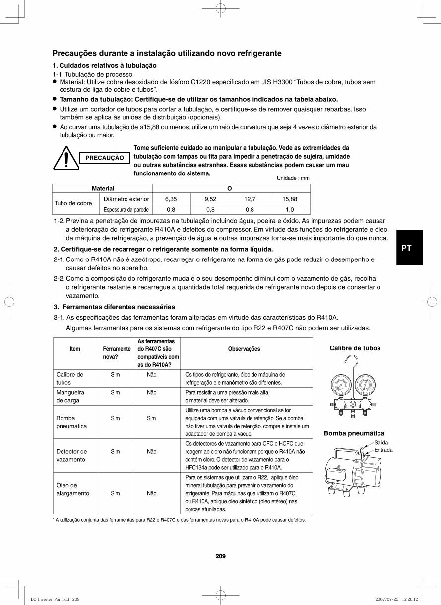
GB
FR
DE
IT
PT
GR
ES
209209
Tome suficiente cuidado ao manipular a tubulação. Vede as extremidades da tubulação com tampas ou fita para impedir a penetração de sujeira, umidade ou outras substâncias estranhas. Essas substâncias podem causar um mau funcionamento do sistema.
As ferramentas Item Ferramente do R407C são Observações nova? compatíveis com as do R410A?
Calibre de Sim Não Os tipos de refrigerante, óleo de máquina de tubos refrigeração e e manômetro são diferentes.
Mangueira Sim Não Para resistir a uma pressão mais alta, de carga o material deve ser alterado.
Utilize uma bomba a vácuo convencional se for Bomba Sim Sim equipada com uma válvula de retenção. Se a bomba pneumática não tiver uma válvula de retenção, compre e instale um adaptador de bomba a vácuo.
Os detectores de vazamento para CFC e HCFC que Detector de Sim Não reagem ao cloro não funcionam porque o R410A não vazamento contém cloro. O detector de vazamento para o HFC134a pode ser utilizado para o R410A.
Para os sistemas que utilizam o R22, aplique óleo Óleo de mineral tubulação para prevenir o vazamento do alargamento Sim Não efrigerante. Para máquinas que utilizam o R407C ou R410A, aplique óleo sintético (óleo etéreo) nas porcas afuniladas.
1-2. Previna a penetração de impurezas na tubulação incluindo água, poeira e óxido. As impurezas podem causar a deterioração do refrigerante R410A e defeitos do compressor. Em virtude das funções do refrigerante e óleo da máquina de refrigeração, a prevenção de água e outras impurezas torna-se mais importante do que nunca.
2. Certifique-se de recarregar o refrigerante somente na forma líquida.
2-1. Como o R410A não é azeótropo, recarregar o refrigerante na forma de gás pode reduzir o desempenho e causar defeitos no aparelho.
2-2. Como a composição do refrigerante muda e o seu desempenho diminui com o vazamento de gás, recolha o refrigerante restante e recarregue a quantidade total requerida de refrigerante novo depois de consertar o vazamento.
3. Ferramentas diferentes necessárias
3-1. As especificações das ferramentas foram alteradas em virtude das características do R410A.
Algumas ferramentas para os sistemas com refrigerante do tipo R22 e R407C não podem ser utilizadas.
Unidade : mm
Precauções durante a instalação utilizando novo refrigerante 1. Cuidados relativos à tubulação1-1. Tubulação de processo● Material: Utilize cobre desoxidado de fósforo C1220 especificado em JIS H3300 “Tubos de cobre, tubos sem
costura de liga de cobre e tubos”.● Tamanho da tubulação: Certifique-se de utilizar os tamanhos indicados na tabela abaixo.● Utilize um cortador de tubos para cortar a tubulação, e certifique-se de remover quaisquer rebarbas. Isso
também se aplica às uniões de distribuição (opcionais).● Ao curvar uma tubulação de ø15,88 ou menos, utilize um raio de curvatura que seja 4 vezes o diâmetro exterior da
tubulação ou maior.
* A utilização conjunta das ferramentas para R22 e R407C e das ferramentas novas para o R410A pode causar defeitos.
Calibre de tubos
Bomba pneumáticaSaídaEntrada
PRECAUÇÃO
Material O
Tubo de cobre Diâmetro exterior 6,35 9,52 12,7 15,88
Espessura da parede 0,8 0,8 0,8 1,0
DC_Inverter_Por.indd 209DC_Inverter_Por.indd 209 2007/07/25 12:20:122007/07/25 12:20:12
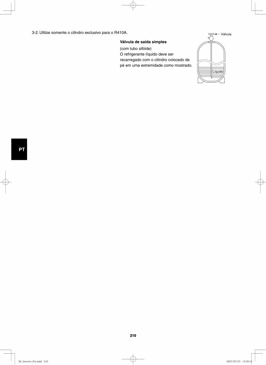
GB
FR
DE
IT
PT
GR
ES
210210
Válvula
Líquido
3-2. Utilize somente o cilindro exclusivo para o R410A.
Válvula de saída simples
(com tubo sifóide)O refrigerante líquido deve ser recarregado com o cilindro colocado de pé em uma extremidade como mostrado.
DC_Inverter_Por.indd 210DC_Inverter_Por.indd 210 2007/07/25 12:20:122007/07/25 12:20:12
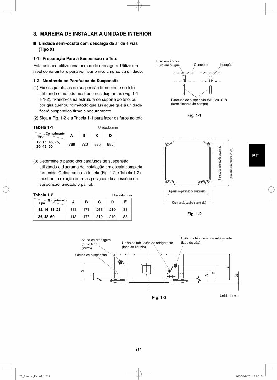
GB
FR
DE
IT
PT
GR
ES
211211
3. MANEIRA DE INSTALAR A UNIDADE INTERIOR
■ Unidade semi-oculta com descarga de ar de 4 vias (Tipo X)
1-1. Preparação Para a Suspensão no Teto
Esta unidade utiliza uma bomba de drenagem. Utilize um nível de carpinteiro para verificar o nivelamento da unidade.
1-2. Montando os Parafusos de Suspensão
(1) Fixe os parafusos de suspensão firmemente no teto utilizando o método mostrado nos diagramas (Fig. 1-1 e 1-2), fixando-os na estrutura de suporte do teto, ou por qualquer outro método que assegure que a unidade ficará suspendida firme e seguramente.
(2) Siga a Fig. 1-2 e a Tabela 1-1 para fazer os furos no teto.
Tabela 1-1 Unidade: mm
(3) Determine o passo dos parafusos de suspensão utilizando o diagrama de instalação em escala completa fornecido. O diagrama e a tabela (Fig. 1-2 e Tabela 1-2) mostram a relação entre as posições do acessório de suspensão, unidade e painel.
Tabela 1-2 Unidade: mm
Fig. 1-1
Fig. 1-2
Fig. 1-3
Furo em âncoraFuro em plugue Concreto Inserção
Parafuso de suspensão (M10 ou 3/8")(fornecimento de campo)
Tipo A B C D
788 723 88588512, 16, 18, 25, 36, 48, 60
Comprimento
A B C D
113 173
173
210
210
256
36, 48, 60
12, 16, 18, 25
E
88
88319113
TipoComprimento
D (d
imen
são d
a abe
rtura
no te
to)
C (dimensão da abertura no teto)
A (passo do parafuso de suspensão)
B (pa
sso d
o para
fuso d
e sus
pens
ão)
E A
B
C
D
35
Orelha de suspensão
União da tubulação do refrigerante(lado do líquido)
União da tubulação do refrigerante(lado do gás)
Saída de drenagem(outro lado) (VP25)
Unidade: mm
DC_Inverter_Por.indd 211DC_Inverter_Por.indd 211 2007/07/25 12:20:122007/07/25 12:20:12
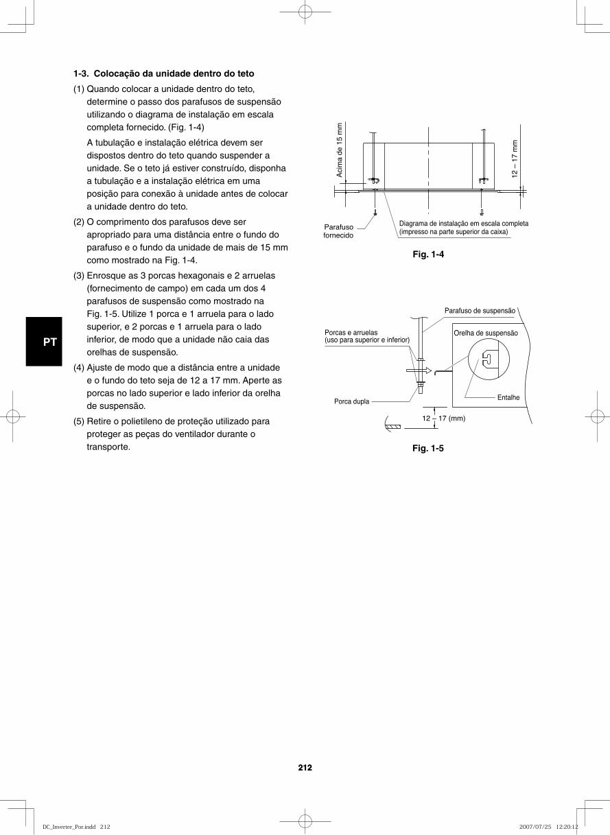
GB
FR
DE
IT
PT
GR
ES
212212
Fig. 1-4
Fig. 1-5
1-3. Colocação da unidade dentro do teto
(1) Quando colocar a unidade dentro do teto, determine o passo dos parafusos de suspensão utilizando o diagrama de instalação em escala completa fornecido. (Fig. 1-4)
A tubulação e instalação elétrica devem ser dispostos dentro do teto quando suspender a unidade. Se o teto já estiver construído, disponha a tubulação e a instalação elétrica em uma posição para conexão à unidade antes de colocar a unidade dentro do teto.
(2) O comprimento dos parafusos deve ser apropriado para uma distância entre o fundo do parafuso e o fundo da unidade de mais de 15 mm como mostrado na Fig. 1-4.
(3) Enrosque as 3 porcas hexagonais e 2 arruelas (fornecimento de campo) em cada um dos 4 parafusos de suspensão como mostrado na Fig. 1-5. Utilize 1 porca e 1 arruela para o lado superior, e 2 porcas e 1 arruela para o lado inferior, de modo que a unidade não caia das orelhas de suspensão.
(4) Ajuste de modo que a distância entre a unidade e o fundo do teto seja de 12 a 17 mm. Aperte as porcas no lado superior e lado inferior da orelha de suspensão.
(5) Retire o polietileno de proteção utilizado para proteger as peças do ventilador durante o transporte.
Diagrama de instalação em escala completa(impresso na parte superior da caixa)
Parafusofornecido
Aci
ma
de 1
5 m
m
12 –
17
mm
12 – 17 (mm)
Parafuso de suspensão
Orelha de suspensãoPorcas e arruelas(uso para superior e inferior)
EntalhePorca dupla
DC_Inverter_Por.indd 212DC_Inverter_Por.indd 212 2007/07/25 12:20:122007/07/25 12:20:12
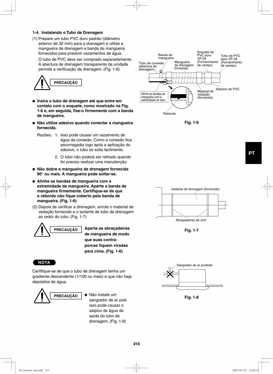
GB
FR
DE
IT
PT
GR
ES
213213
1-4. Instalando o Tubo de Drenagem(1) Prepare um tubo PVC duro padrão (diâmetro
exterior de 32 mm) para a drenagem e utilize a mangueira de drenagem e banda de mangueira fornecidos para prevenir vazamentos de água.
O tubo de PVC deve ser comprado separadamente. A abertura de drenagem transparente da unidade permite a verificação da drenagem. (Fig. 1-6)
● Insira o tubo de drenagem até que entre em contato com o soquete, como mostrado na Fig. 1-6 e, em seguida, fixe-o firmemente com a banda de mangueira.
● Não utilize adesivo quando conectar a mangueira fornecida.
Razões: 1. Isso pode causar um vazamento de água da conexão. Como a conexão fica escorregadia logo após a aplicação do adesivo, o tubo se solta facilmente.
2. O tubo não poderá ser retirado quando for preciso realizar uma manutenção.
● Não dobre a mangueira de drenagem fornecida 90° ou mais. A mangueira pode soltar-se.
● Alinhe as bandas de mangueira com a extremidade da mangueira. Aperte a banda de mangueira firmemente. Certifique-se de que o rebordo não fique coberto pela banda de mangueira. (Fig. 1-6)
(2) Depois de verificar a drenagem, enrole o material de vedação fornecido e o isolante de tubo de drenagem ao redor do tubo. (Fig. 1-7)
NOTA
Certifique-se de que o tubo de drenagem tenha um gradiente descendente (1/100 ou mais) e que não haja depósitos de água.
PRECAUÇÃO
PRECAUÇÃO Aperte as abraçadeiras de mangueira de modo que suas contra-porcas fiquem viradas para cima. (Fig. 1-6)
PRECAUÇÃO ● Não instale um sangrador de ar pois isso pode causar o salpico de água da saída do tubo de drenagem. (Fig. 1-8)
Fig. 1-6
Fig. 1-7
Fig. 1-8
Rebordo
Banda de mangueira
Mangueira de drenagem fornecida
Tubo de conexão(abertura de drenagem)
Material de vedação (fornecido)
Soquete de PVC duro VP-25 (Fornecimento de campo)
Tubo de PVC duro VP-25 (Fornecimento de campo)
Adesivo de PVC
Alinhe as bandas de mangueira com a extremidade do tubo.
Abraçadeiras de vinil
Isolante de drenagem (fornecido)
Sangrador de ar proibido
DC_Inverter_Por.indd 213DC_Inverter_Por.indd 213 2007/07/25 12:20:132007/07/25 12:20:13
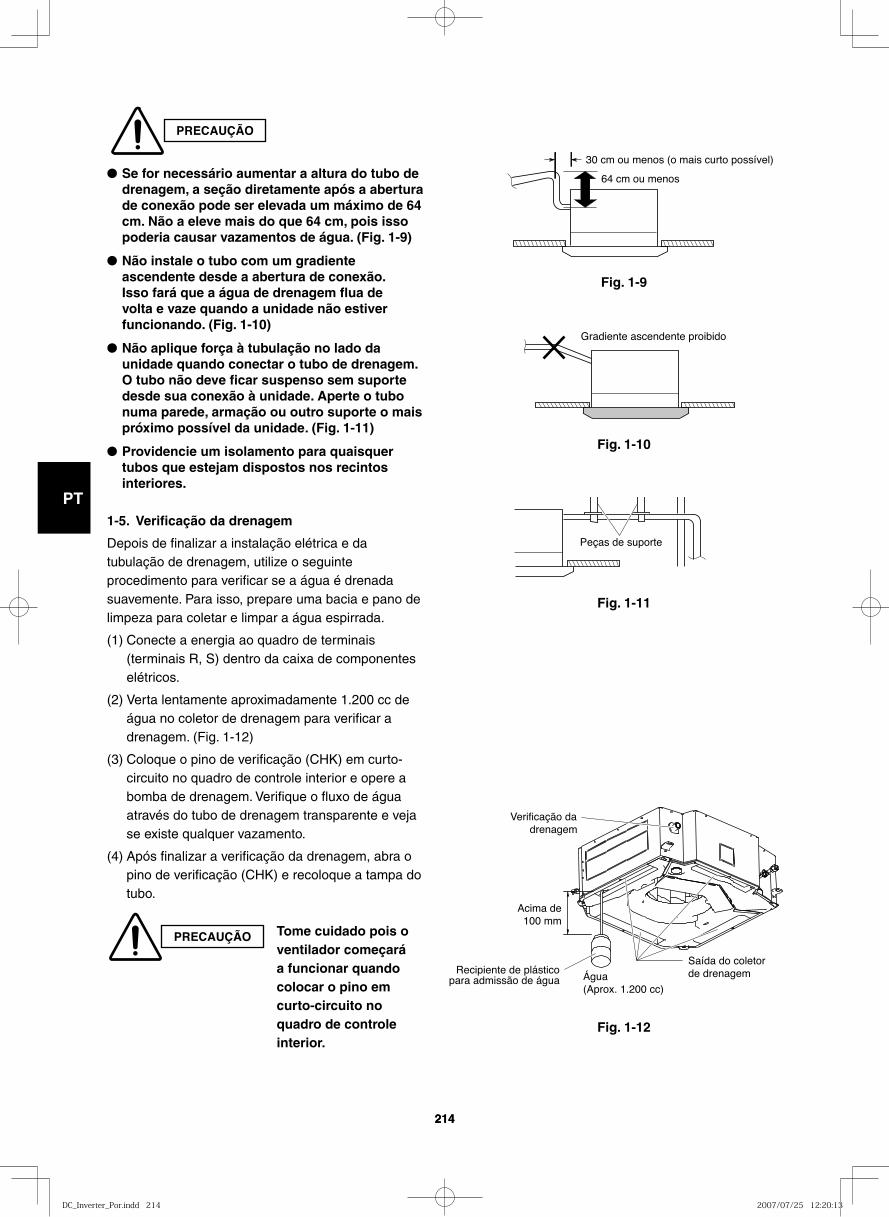
GB
FR
DE
IT
PT
GR
ES
214214
Fig. 1-9
30 cm ou menos (o mais curto possível)
64 cm ou menos
Fig. 1-10
Gradiente ascendente proibido
Fig. 1-11
Fig. 1-12
Peças de suporte
Água(Aprox. 1.200 cc)
Acima de 100 mm
Saída do coletor de drenagem
Verificação dadrenagem
Recipiente de plásticopara admissão de água
PRECAUÇÃO
● Se for necessário aumentar a altura do tubo de drenagem, a seção diretamente após a abertura de conexão pode ser elevada um máximo de 64 cm. Não a eleve mais do que 64 cm, pois isso poderia causar vazamentos de água. (Fig. 1-9)
● Não instale o tubo com um gradiente ascendente desde a abertura de conexão. Isso fará que a água de drenagem flua de volta e vaze quando a unidade não estiver funcionando. (Fig. 1-10)
● Não aplique força à tubulação no lado da unidade quando conectar o tubo de drenagem. O tubo não deve ficar suspenso sem suporte desde sua conexão à unidade. Aperte o tubo numa parede, armação ou outro suporte o mais próximo possível da unidade. (Fig. 1-11)
● Providencie um isolamento para quaisquer tubos que estejam dispostos nos recintos interiores.
1-5. Verificação da drenagem
Depois de finalizar a instalação elétrica e da tubulação de drenagem, utilize o seguinte procedimento para verificar se a água é drenada suavemente. Para isso, prepare uma bacia e pano de limpeza para coletar e limpar a água espirrada.
(1) Conecte a energia ao quadro de terminais (terminais R, S) dentro da caixa de componentes elétricos.
(2) Verta lentamente aproximadamente 1.200 cc de água no coletor de drenagem para verificar a drenagem. (Fig. 1-12)
(3) Coloque o pino de verificação (CHK) em curto-circuito no quadro de controle interior e opere a bomba de drenagem. Verifique o fluxo de água através do tubo de drenagem transparente e veja se existe qualquer vazamento.
(4) Após finalizar a verificação da drenagem, abra o pino de verificação (CHK) e recoloque a tampa do tubo.
PRECAUÇÃO Tome cuidado pois o ventilador começará a funcionar quando colocar o pino em curto-circuito no quadro de controle interior.
DC_Inverter_Por.indd 214DC_Inverter_Por.indd 214 2007/07/25 12:20:132007/07/25 12:20:13
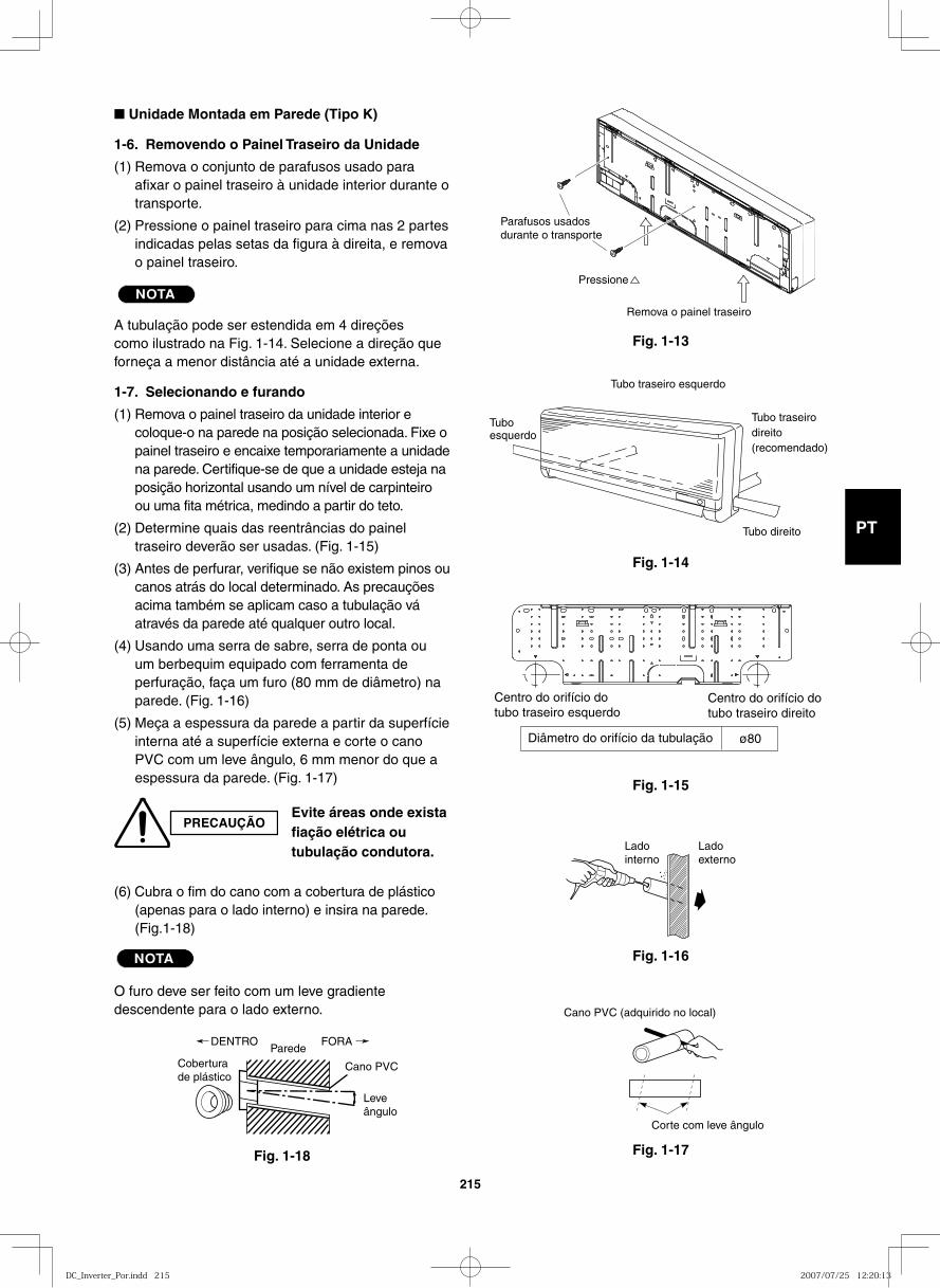
GB
FR
DE
IT
PT
GR
ES
215
■ Unidade Montada em Parede (Tipo K)
1-6. Removendo o Painel Traseiro da Unidade
(1) Remova o conjunto de parafusos usado para afixar o painel traseiro à unidade interior durante o transporte.
(2) Pressione o painel traseiro para cima nas 2 partes indicadas pelas setas da figura à direita, e remova o painel traseiro.
NOTA
A tubulação pode ser estendida em 4 direções como ilustrado na Fig. 1-14. Selecione a direção que forneça a menor distância até a unidade externa.
1-7. Selecionando e furando
(1) Remova o painel traseiro da unidade interior e coloque-o na parede na posição selecionada. Fixe o painel traseiro e encaixe temporariamente a unidade na parede. Certifique-se de que a unidade esteja na posição horizontal usando um nível de carpinteiro ou uma fita métrica, medindo a partir do teto.
(2) Determine quais das reentrâncias do painel traseiro deverão ser usadas. (Fig. 1-15)
(3) Antes de perfurar, verifique se não existem pinos ou canos atrás do local determinado. As precauções acima também se aplicam caso a tubulação vá através da parede até qualquer outro local.
(4) Usando uma serra de sabre, serra de ponta ou um berbequim equipado com ferramenta de perfuração, faça um furo (80 mm de diâmetro) na parede. (Fig. 1-16)
(5) Meça a espessura da parede a partir da superfície interna até a superfície externa e corte o cano PVC com um leve ângulo, 6 mm menor do que a espessura da parede. (Fig. 1-17)
(6) Cubra o fim do cano com a cobertura de plástico (apenas para o lado interno) e insira na parede. (Fig.1-18)
NOTA
O furo deve ser feito com um leve gradiente descendente para o lado externo.
Fig. 1-13
Fig. 1-14
Fig. 1-15
Fig. 1-16
Fig. 1-17Fig. 1-18
PRECAUÇÃOEvite áreas onde exista fiação elétrica ou tubulação condutora.
Coberturade plástico
DENTROParede
Leveângulo
Cano PVC
FORA
Corte com leve ângulo
Cano PVC (adquirido no local)
Ladointerno
Ladoexterno
Centro do orifício do tubo traseiro esquerdo
Centro do orifício do tubo traseiro direito
Diâmetro do orifício da tubulação ø80
Tuboesquerdo
Tubo traseirodireito(recomendado)
Tubo direito
Tubo traseiro esquerdo
Remova o painel traseiro
Pressione
Parafusos usados durante o transporte
DC_Inverter_Por.indd 215DC_Inverter_Por.indd 215 2007/07/25 12:20:132007/07/25 12:20:13
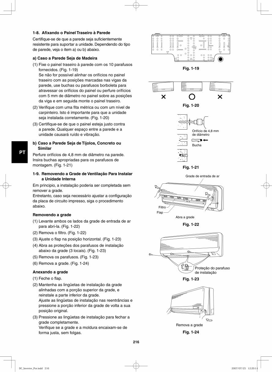
GB
FR
DE
IT
PT
GR
ES
216
Fig. 1-19
1-8. Afixando o Painel Traseiro à Parede
Certifique-se de que a parede seja suficientemente resistente para suportar a unidade. Dependendo do tipo de parede, veja o item a) ou b) abaixo.
a) Caso a Parede Seja de Madeira
(1) Fixe o painel traseiro à parede com os 10 parafusos fornecidos. (Fig. 1-19)
Se não for possível alinhar os orifícios no painel traseiro com as posições marcadas nas vigas da parede, use buchas ou parafusos borboleta para atravessar os orifícios do painel ou perfure orifícios com 5 mm de diâmetro no painel sobre as posições da viga e em seguida monte o painel traseiro.
(2) Verifique com uma fita métrica ou com um nível de carpinteiro. Isto é importante para que a unidade seja instalada corretamente. (Fig. 1-20)
(3) Certifique-se de que o painel esteja justo contra a parede. Qualquer espaço entre a parede e a unidade causará ruído e vibração.
b) Caso a Parede Seja de Tijolos, Concreto ou Similar
Perfure orifícios de 4,8 mm de diâmetro na parede. Insira buchas apropriadas para os parafusos de montagem. (Fig. 1-21)
1-9. Removendo a Grade de Ventilação Para Instalar a Unidade Interna
Em principio, a instalação poderia ser completada sem remover a grade.Entretanto, caso seja necessário ajustar a configuração da placa de circuito impresso, siga o procedimento abaixo.
Removendo a grade
(1) Levante ambos os lados da grade de entrada de ar para abri-la. (Fig. 1-22)
(2) Remova o filtro. (Fig. 1-22)
(3) Ajuste o flap na posição horizontal. (Fig. 1-23)
(4) Abra as proteções dos parafusos de instalação abaixo da grade (3 locais). (Fig. 1-23)
(5) Remova os parafusos. (Fig. 1-23)
(6) Remova a grade. (Fig. 1-24)
Anexando a grade
(1) Feche o flap.
(2) Mantenha as lingüetas de instalação da grade alinhadas com a porção superior da grade, e reinstale a parte inferior da grade.
Ajuste as lingüetas de instalação nas reentrâncias e pressione a porção inferior da grade de volta a sua posição original.
(3) Pressione as lingüetas de instalação para fechar a grade completamente.
Verifique se a grade e a moldura encaixam-se de forma justa, sem folgas.
Fig. 1-20
Fig. 1-21
Fig. 1-22
Fig. 1-23
Fig. 1-24
Orifício de 4,8 mmde diâmetro
Bucha
Grade de entrada de ar
Filtro
Flap
Abra a grade
Proteção do parafuso de instalação
Remova a grade
DC_Inverter_Por.indd 216DC_Inverter_Por.indd 216 2007/07/25 12:20:142007/07/25 12:20:14
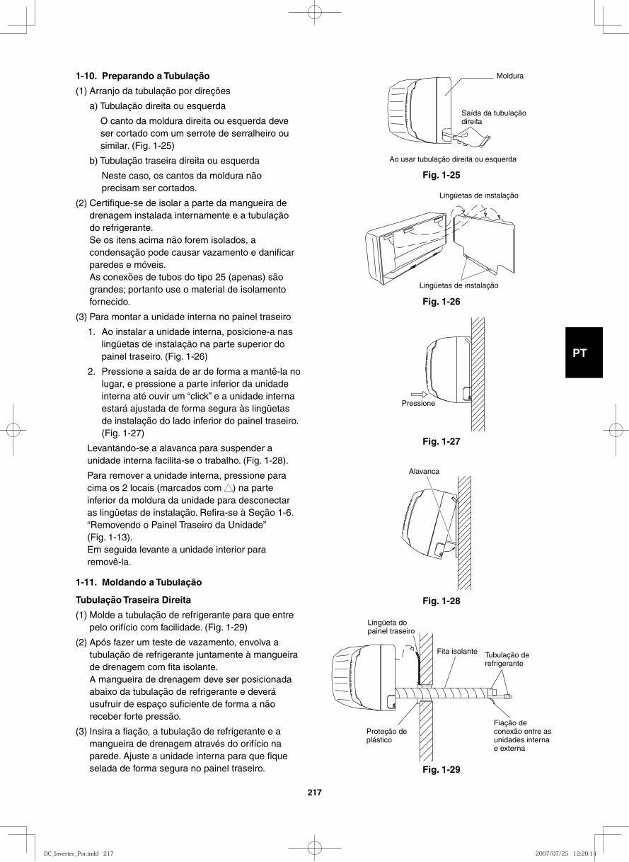
GB
FR
DE
IT
PT
GR
ES
217
1-10. Preparando a Tubulação
(1) Arranjo da tubulação por direções
a) Tubulação direita ou esquerda
O canto da moldura direita ou esquerda deve ser cortado com um serrote de serralheiro ou similar. (Fig. 1-25)
b) Tubulação traseira direita ou esquerda
Neste caso, os cantos da moldura não precisam ser cortados.
(2) Certifique-se de isolar a parte da mangueira de drenagem instalada internamente e a tubulação do refrigerante.
Se os itens acima não forem isolados, a condensação pode causar vazamento e danificar paredes e móveis.
As conexões de tubos do tipo 25 (apenas) são grandes; portanto use o material de isolamento fornecido.
(3) Para montar a unidade interna no painel traseiro
1. Ao instalar a unidade interna, posicione-a nas lingüetas de instalação na parte superior do painel traseiro. (Fig. 1-26)
2. Pressione a saída de ar de forma a mantê-la no lugar, e pressione a parte inferior da unidade interna até ouvir um “click” e a unidade interna estará ajustada de forma segura às lingüetas de instalação do lado inferior do painel traseiro. (Fig. 1-27)
Levantando-se a alavanca para suspender a unidade interna facilita-se o trabalho. (Fig. 1-28).
Para remover a unidade interna, pressione para cima os 2 locais (marcados com ▲▲) na parte inferior da moldura da unidade para desconectar as lingüetas de instalação. Refira-se à Seção 1-6. “Removendo o Painel Traseiro da Unidade”(Fig. 1-13).Em seguida levante a unidade interior para removê-la.
1-11. Moldando a Tubulação
Tubulação Traseira Direita
(1) Molde a tubulação de refrigerante para que entre pelo orifício com facilidade. (Fig. 1-29)
(2) Após fazer um teste de vazamento, envolva a tubulação de refrigerante juntamente à mangueira de drenagem com fita isolante.
A mangueira de drenagem deve ser posicionada abaixo da tubulação de refrigerante e deverá usufruir de espaço suficiente de forma a não receber forte pressão.
(3) Insira a fiação, a tubulação de refrigerante e a mangueira de drenagem através do orifício na parede. Ajuste a unidade interna para que fique selada de forma segura no painel traseiro.
Fig. 1-25
Moldura
Saída da tubulaçãodireita
Ao usar tubulação direita ou esquerda
Fig. 1-26
Lingüetas de instalação
Lingüetas de instalação
Fig. 1-27
Pressione
Fig. 1-28
Alavanca
Fig. 1-29
Fita isolante Tubulação derefrigerante
Lingüeta do painel traseiro
Proteção de plástico
Fiação de conexão entre as unidades interna e externa
DC_Inverter_Por.indd 217DC_Inverter_Por.indd 217 2007/07/25 12:20:142007/07/25 12:20:14
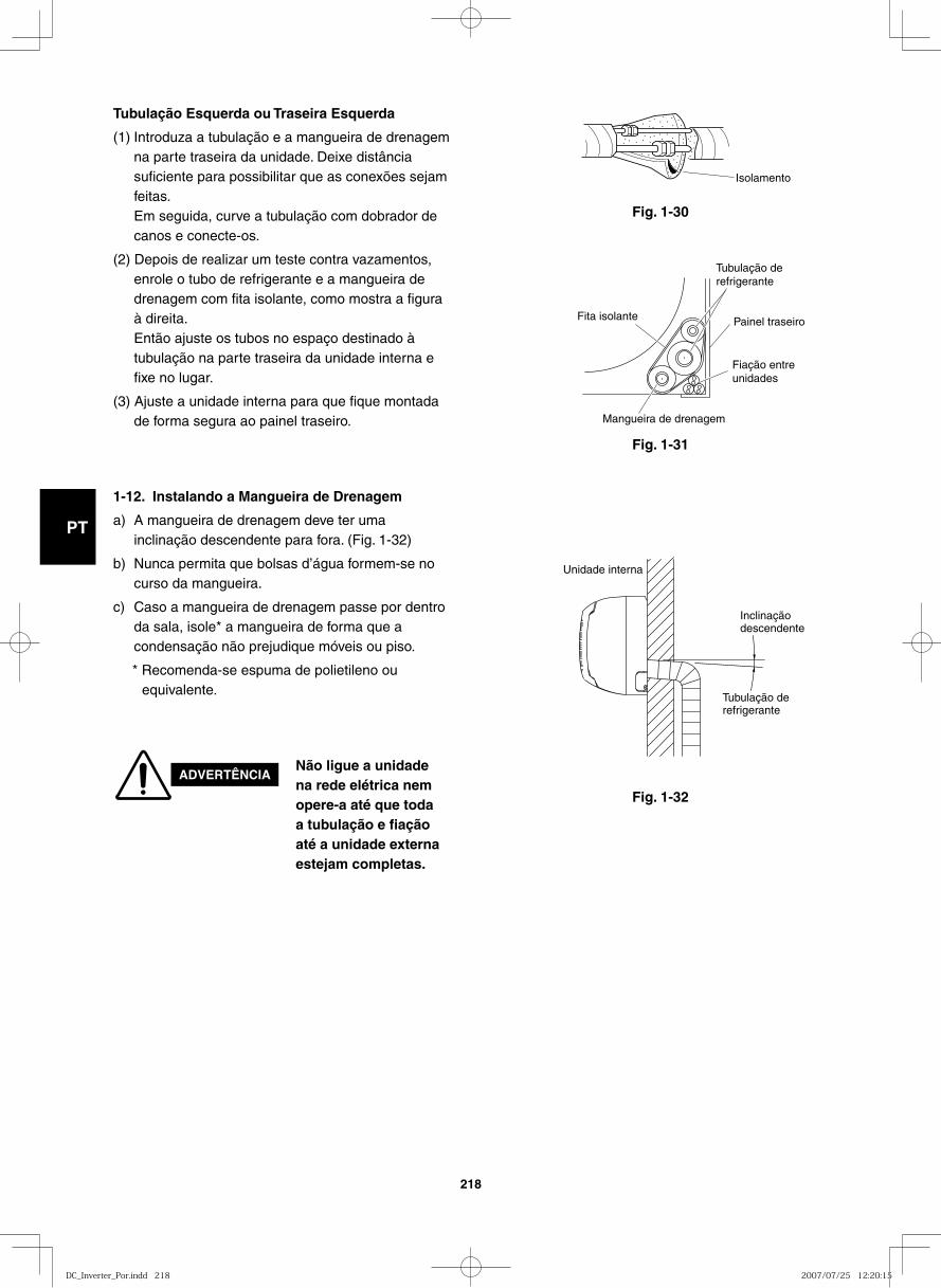
GB
FR
DE
IT
PT
GR
ES
218
Fig. 1-32
Fig. 1-30
Isolamento
Fig. 1-31
Fita isolante Painel traseiro
Fiação entreunidades
Tubulação de refrigerante
Mangueira de drenagem
Unidade interna
Inclinaçãodescendente
Tubulação derefrigerante
1-12. Instalando a Mangueira de Drenagem
a) A mangueira de drenagem deve ter uma inclinação descendente para fora. (Fig. 1-32)
b) Nunca permita que bolsas d’água formem-se no curso da mangueira.
c) Caso a mangueira de drenagem passe por dentro da sala, isole* a mangueira de forma que a condensação não prejudique móveis ou piso.
* Recomenda-se espuma de polietileno ou equivalente.
ADVERTÊNCIANão ligue a unidade na rede elétrica nem opere-a até que toda a tubulação e fiação até a unidade externa estejam completas.
Tubulação Esquerda ou Traseira Esquerda
(1) Introduza a tubulação e a mangueira de drenagem na parte traseira da unidade. Deixe distância suficiente para possibilitar que as conexões sejam feitas.
Em seguida, curve a tubulação com dobrador de canos e conecte-os.
(2) Depois de realizar um teste contra vazamentos, enrole o tubo de refrigerante e a mangueira de drenagem com fita isolante, como mostra a figura à direita.
Então ajuste os tubos no espaço destinado à tubulação na parte traseira da unidade interna e fixe no lugar.
(3) Ajuste a unidade interna para que fique montada de forma segura ao painel traseiro.
DC_Inverter_Por.indd 218DC_Inverter_Por.indd 218 2007/07/25 12:20:152007/07/25 12:20:15
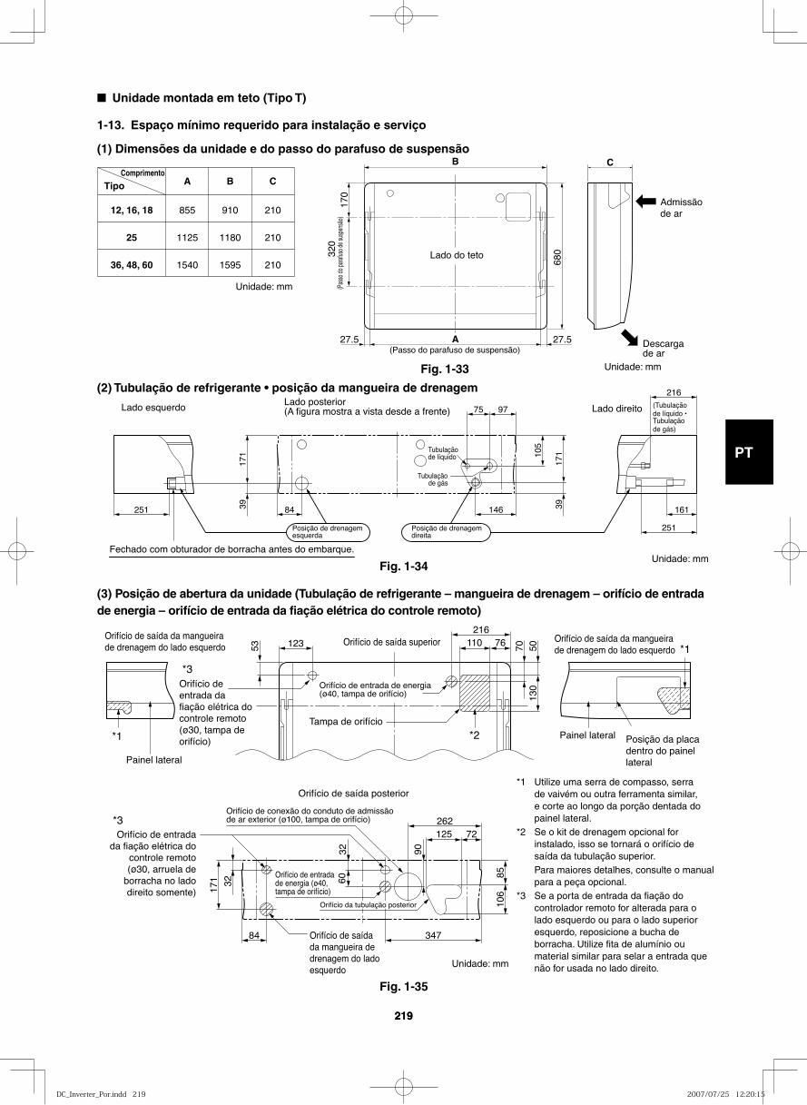
GB
FR
DE
IT
PT
GR
ES
219219
Fig. 1-34
251 84 146 161
75 97
216
39 39
171 10
5
171
251
Tubulação de líquido
Lado direitoLado esquerdoLado posterior(A figura mostra a vista desde a frente)
Fechado com obturador de borracha antes do embarque.
Posição de drenagemesquerda
Posição de drenagemdireita
(Tubulação de líquido • Tubulaçãode gás)
Tubulaçãode gás
■ Unidade montada em teto (Tipo T)
1-13. Espaço mínimo requerido para instalação e serviço
(1) Dimensões da unidade e do passo do parafuso de suspensão
12, 16, 18
25
36, 48, 60
855
1125
1540
910
1180
1595
210
210
210
A B CTipoComprimento
B C
A17
032
0
680
27.5 27.5
Lado do teto
(Passo do parafuso de suspensão)(P
asso
do pa
rafus
o de s
uspe
nsão
)
Admissãode ar
Descarga de ar
(2) Tubulação de refrigerante • posição da mangueira de drenagem
(3) Posição de abertura da unidade (Tubulação de refrigerante – mangueira de drenagem – orifício de entrada de energia – orifício de entrada da fiação elétrica do controle remoto)
53 70123 110 76216
5013
0
Orifício de saída da mangueira de drenagem do lado esquerdo
Orifício de saída da mangueira de drenagem do lado esquerdo
Orifício de saída superior
Orifício de entrada da fiação elétrica do controle remoto (ø30, tampa de orifício)
Orifício de entrada de energia (ø40, tampa de orifício)
Orifício de entrada de energia (ø40, tampa de orifício)
Tampa de orifício
Painel lateral
Posição da placa dentro do painel lateral
Painel lateral
Orifício de saída da mangueira de drenagem do lado esquerdo
84
32
3260
171
347
125 72
8510
6
90
262Orifício de entrada
da fiação elétrica do controle remoto(ø30, arruela de
borracha no lado direito somente)
Orifício de conexão do conduto de admissãode ar exterior (ø100, tampa de orifício)
Orifício de saída posterior
*3
*1
*1
*2
*3
Orifício da tubulação posterior
Fig. 1-33
Fig. 1-35
*1 Utilize uma serra de compasso, serra de vaivém ou outra ferramenta similar, e corte ao longo da porção dentada do painel lateral.
*2 Se o kit de drenagem opcional for instalado, isso se tornará o orifício de saída da tubulação superior.
Para maiores detalhes, consulte o manual para a peça opcional.
*3 Se a porta de entrada da fiação do controlador remoto for alterada para o lado esquerdo ou para o lado superior esquerdo, reposicione a bucha de borracha. Utilize fita de alumínio ou material similar para selar a entrada que não for usada no lado direito.
Unidade: mm
Unidade: mm
Unidade: mm
Unidade: mm
DC_Inverter_Por.indd 219DC_Inverter_Por.indd 219 2007/07/25 12:20:152007/07/25 12:20:15
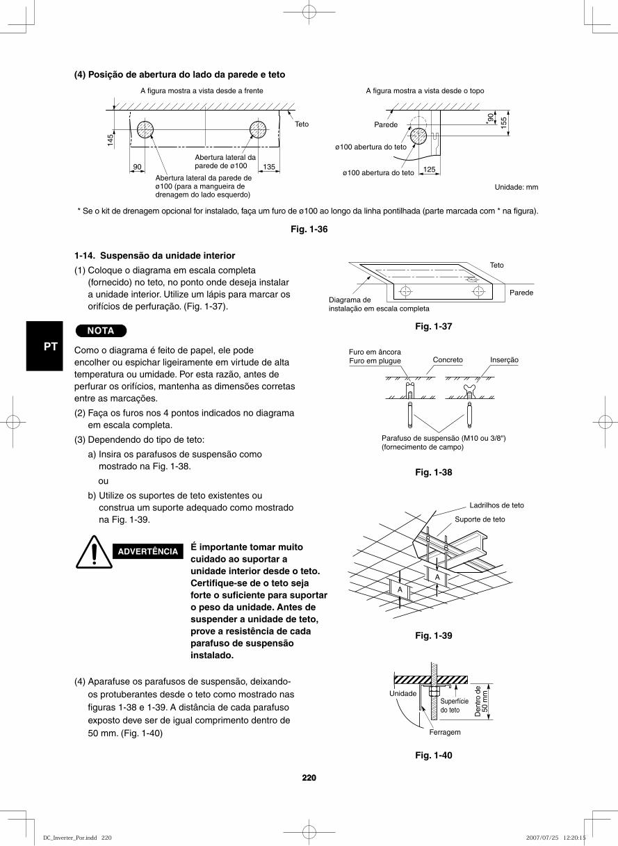
GB
FR
DE
IT
PT
GR
ES
220220
(4) Posição de abertura do lado da parede e teto
90
145
135 125
15590
*
A figura mostra a vista desde a frente A figura mostra a vista desde o topo
Abertura lateral da parede de ø100 (para a mangueira de drenagem do lado esquerdo)
Abertura lateral daparede de ø100
ø100 abertura do teto
ø100 abertura do teto
ParedeTeto
Diagrama de instalação em escala completa
Parede
Teto
Fig. 1-37
Fig. 1-36
Fig. 1-38
1-14. Suspensão da unidade interior
(1) Coloque o diagrama em escala completa (fornecido) no teto, no ponto onde deseja instalar a unidade interior. Utilize um lápis para marcar os orifícios de perfuração. (Fig. 1-37).
NOTA
Como o diagrama é feito de papel, ele pode encolher ou espichar ligeiramente em virtude de alta temperatura ou umidade. Por esta razão, antes de perfurar os orifícios, mantenha as dimensões corretas entre as marcações.
(2) Faça os furos nos 4 pontos indicados no diagrama em escala completa.
(3) Dependendo do tipo de teto:
a) Insira os parafusos de suspensão como mostrado na Fig. 1-38.
ou
b) Utilize os suportes de teto existentes ou construa um suporte adequado como mostrado na Fig. 1-39.
ADVERTÊNCIA É importante tomar muito cuidado ao suportar a unidade interior desde o teto. Certifique-se de o teto seja forte o suficiente para suportar o peso da unidade. Antes de suspender a unidade de teto, prove a resistência de cada parafuso de suspensão instalado.
(4) Aparafuse os parafusos de suspensão, deixando-os protuberantes desde o teto como mostrado nas figuras 1-38 e 1-39. A distância de cada parafuso exposto deve ser de igual comprimento dentro de 50 mm. (Fig. 1-40)
Furo em âncoraFuro em plugue Concreto Inserção
Parafuso de suspensão (M10 ou 3/8")(fornecimento de campo)
Fig. 1-39
Fig. 1-40
Ladrilhos de teto
Suporte de teto
A
A
Superfíciedo teto
Ferragem
Den
tro d
e50
mmUnidade
* Se o kit de drenagem opcional for instalado, faça um furo de ø100 ao longo da linha pontilhada (parte marcada com * na figura).
Unidade: mm
DC_Inverter_Por.indd 220DC_Inverter_Por.indd 220 2007/07/25 12:20:152007/07/25 12:20:15
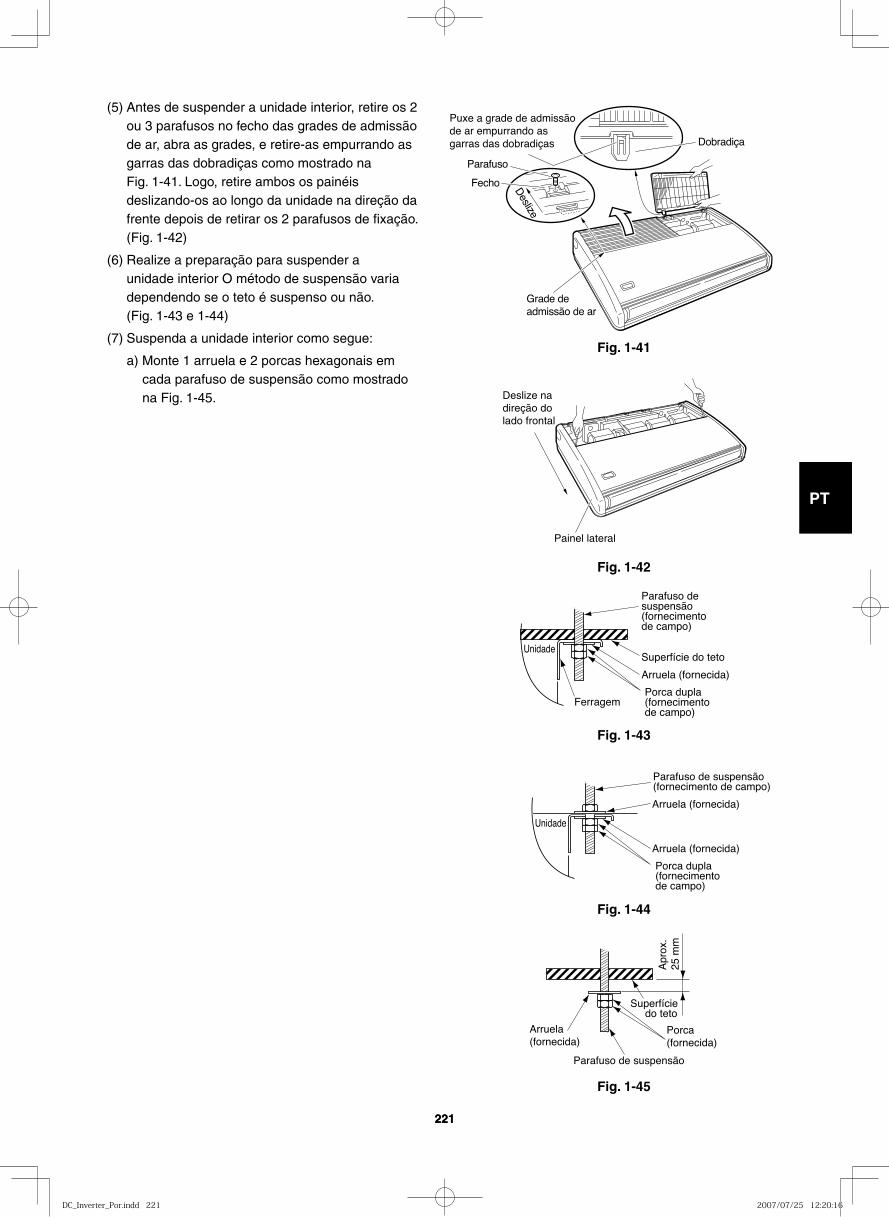
GB
FR
DE
IT
PT
GR
ES
221221
Fig. 1-41
Deslize
Dobradiça
Grade de admissão de ar
Parafuso
Fecho
Puxe a grade de admissão de ar empurrando as garras das dobradiças
Fig. 1-42
Deslize na direção do lado frontal
Painel lateral
Fig. 1-43
Unidade
Parafuso de suspensão(fornecimento de campo)
Superfície do teto
Arruela (fornecida)
Porca dupla(fornecimento de campo)
Ferragem
Fig. 1-44
Arruela (fornecida)
Arruela (fornecida)
Unidade
Porca dupla(fornecimento de campo)
Parafuso de suspensão(fornecimento de campo)
Fig. 1-45
Superfície do teto
Apr
ox.
25 m
m
Parafuso de suspensão
Arruela(fornecida)
Porca(fornecida)
(5) Antes de suspender a unidade interior, retire os 2 ou 3 parafusos no fecho das grades de admissão de ar, abra as grades, e retire-as empurrando as garras das dobradiças como mostrado na Fig. 1-41. Logo, retire ambos os painéis deslizando-os ao longo da unidade na direção da frente depois de retirar os 2 parafusos de fixação. (Fig. 1-42)
(6) Realize a preparação para suspender a unidade interior O método de suspensão varia dependendo se o teto é suspenso ou não. (Fig. 1-43 e 1-44)
(7) Suspenda a unidade interior como segue:
a) Monte 1 arruela e 2 porcas hexagonais em cada parafuso de suspensão como mostrado na Fig. 1-45.
DC_Inverter_Por.indd 221DC_Inverter_Por.indd 221 2007/07/25 12:20:162007/07/25 12:20:16
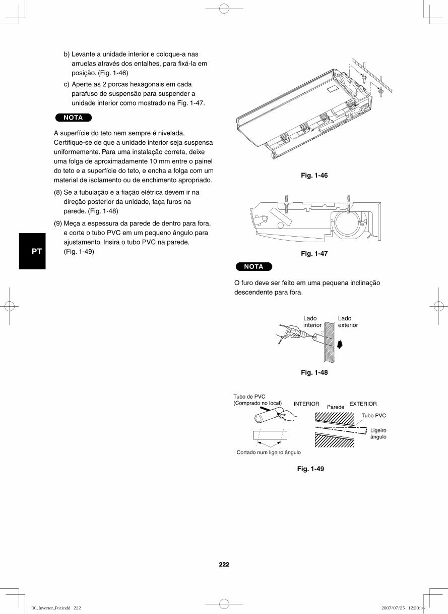
GB
FR
DE
IT
PT
GR
ES
222222
Fig. 1-46
Fig. 1-47
Fig. 1-48
Ladointerior
Ladoexterior
Fig. 1-49
Cortado num ligeiro ângulo
Tubo de PVC(Comprado no local) INTERIOR
Parede
Ligeiroângulo
Tubo PVC
EXTERIOR
b) Levante a unidade interior e coloque-a nas arruelas através dos entalhes, para fixá-la em posição. (Fig. 1-46)
c) Aperte as 2 porcas hexagonais em cada parafuso de suspensão para suspender a unidade interior como mostrado na Fig. 1-47.
NOTA
A superfície do teto nem sempre é nivelada. Certifique-se de que a unidade interior seja suspensa uniformemente. Para uma instalação correta, deixe uma folga de aproximadamente 10 mm entre o painel do teto e a superfície do teto, e encha a folga com um material de isolamento ou de enchimento apropriado.
(8) Se a tubulação e a fiação elétrica devem ir na direção posterior da unidade, faça furos na parede. (Fig. 1-48)
(9) Meça a espessura da parede de dentro para fora, e corte o tubo PVC em um pequeno ângulo para ajustamento. Insira o tubo PVC na parede. (Fig. 1-49)
NOTA
O furo deve ser feito em uma pequena inclinação descendente para fora.
DC_Inverter_Por.indd 222DC_Inverter_Por.indd 222 2007/07/25 12:20:162007/07/25 12:20:16
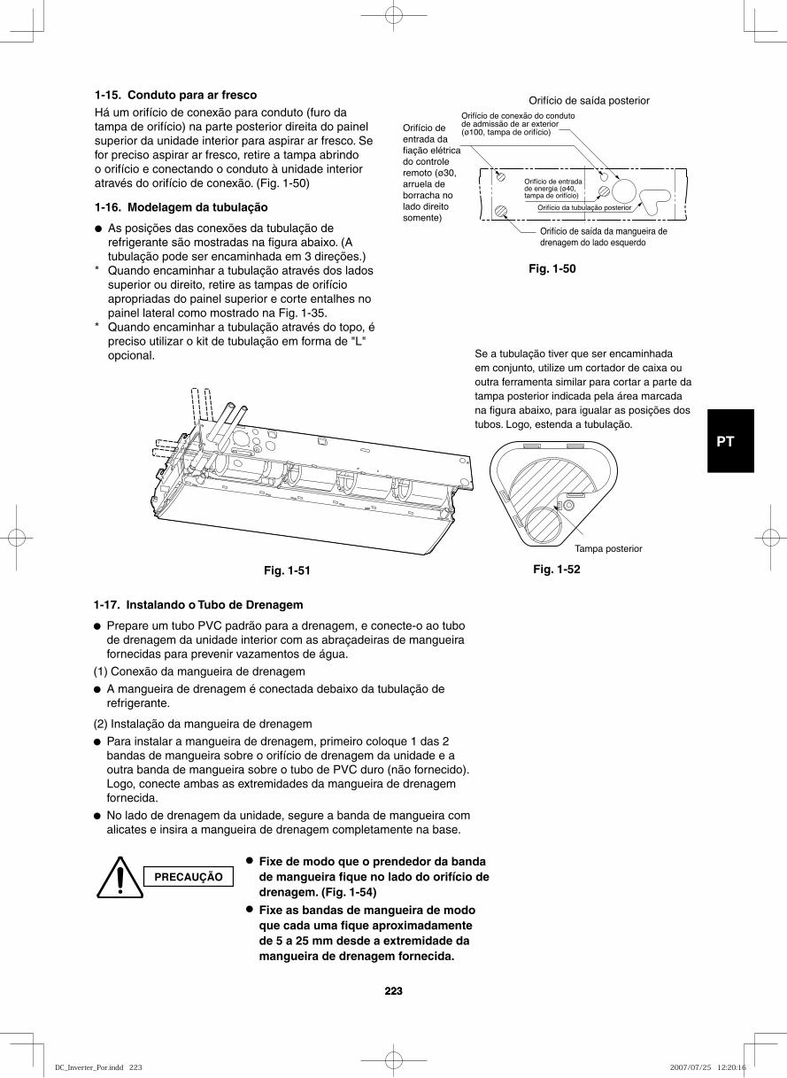
GB
FR
DE
IT
PT
GR
ES
223223
1-15. Conduto para ar frescoHá um orifício de conexão para conduto (furo da tampa de orifício) na parte posterior direita do painel superior da unidade interior para aspirar ar fresco. Se for preciso aspirar ar fresco, retire a tampa abrindo o orifício e conectando o conduto à unidade interior através do orifício de conexão. (Fig. 1-50)
1-16. Modelagem da tubulação
● As posições das conexões da tubulação de refrigerante são mostradas na figura abaixo. (A tubulação pode ser encaminhada em 3 direções.)
* Quando encaminhar a tubulação através dos lados superior ou direito, retire as tampas de orifício apropriadas do painel superior e corte entalhes no painel lateral como mostrado na Fig. 1-35.
* Quando encaminhar a tubulação através do topo, é preciso utilizar o kit de tubulação em forma de "L" opcional.
Orifício de entrada de energia (ø40, tampa de orifício)
Orifício de saída da mangueira de drenagem do lado esquerdo
Orifício de entrada da fiação elétrica do controle remoto (ø30, arruela de borracha no lado direito somente)
Orifício de conexão do conduto de admissão de ar exterior (ø100, tampa de orifício)
Orifício de saída posterior
Orifício da tubulação posterior
Fig. 1-50
Tampa posterior
PRECAUÇÃO
● Fixe de modo que o prendedor da banda de mangueira fique no lado do orifício de drenagem. (Fig. 1-54)
● Fixe as bandas de mangueira de modo que cada uma fique aproximadamente de 5 a 25 mm desde a extremidade da mangueira de drenagem fornecida.
Se a tubulação tiver que ser encaminhada em conjunto, utilize um cortador de caixa ou outra ferramenta similar para cortar a parte da tampa posterior indicada pela área marcada na figura abaixo, para igualar as posições dos tubos. Logo, estenda a tubulação.
Fig. 1-51 Fig. 1-52
1-17. Instalando o Tubo de Drenagem
● Prepare um tubo PVC padrão para a drenagem, e conecte-o ao tubo de drenagem da unidade interior com as abraçadeiras de mangueira fornecidas para prevenir vazamentos de água.
(1) Conexão da mangueira de drenagem
● A mangueira de drenagem é conectada debaixo da tubulação de refrigerante.
(2) Instalação da mangueira de drenagem
● Para instalar a mangueira de drenagem, primeiro coloque 1 das 2 bandas de mangueira sobre o orifício de drenagem da unidade e a outra banda de mangueira sobre o tubo de PVC duro (não fornecido). Logo, conecte ambas as extremidades da mangueira de drenagem fornecida.
● No lado de drenagem da unidade, segure a banda de mangueira com alicates e insira a mangueira de drenagem completamente na base.
DC_Inverter_Por.indd 223DC_Inverter_Por.indd 223 2007/07/25 12:20:162007/07/25 12:20:16
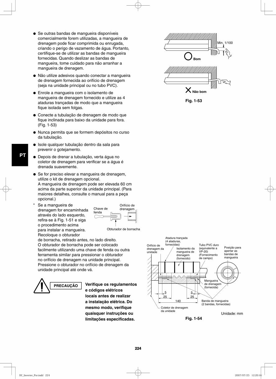
GB
FR
DE
IT
PT
GR
ES
224224
14025 25
55
Coletor de drenagem da unidade
Orifício de drenagem da unidade
Atadura trançada (4 ataduras, fornecidas)
Isolamento da mangueira de drenagem (fornecido)
Tubo PVC duro (equivalente a VP-20) (Fornecimento de campo)
Posição para apertar as bandas de mangueira
Mangueira de drenagem (fornecida)
Banda de mangueira (2 bandas, fornecidas)
Fig. 1-54
Bom
Min. 1/100
Não bom
Fig. 1-53
● Se outras bandas de mangueira disponíveis comercialmente forem utilizadas, a mangueira de drenagem pode ficar comprimida ou enrugada, criando o perigo de vazamento de água. Portanto, certifique-se de utilizar as bandas de mangueira fornecidas. Quando deslizar as bandas de mangueira, tome cuidado para não arranhar a mangueira de drenagem.
● Não utilize adesivos quando conectar a mangueira de drenagem fornecida ao orifício de drenagem (seja na unidade principal ou no tubo PVC).
● Enrole a mangueira com o isolamento de mangueira de drenagem fornecido e utilize as 4 ataduras trançadas de modo que a mangueira fique isolada sem folgas.
● Conecte a tubulação de drenagem de modo que fique inclinada para baixo da unidade para fora. (Fig. 1-53)
● Nunca permita que se formem depósitos no curso da tubulação.
● Isole qualquer tubulação dentro da sala para prevenir o gotejamento.
● Depois de drenar a tubulação, verta água no coletor de drenagem para verificar se a água é drenada suavemente.
● Se for preciso elevar a mangueira de drenagem, utilize o kit de drenagem opcional.A mangueira de drenagem pode ser elevada 60 cm acima da parte superior da unidade principal. (Para maiores detalhes, consulte o manual para a peça opcional.)
* Se a mangueira de drenagem for encaminhada através do lado esquerdo, refira-se à Fig. 1-51 e siga o procedimento acima para instalar a mangueira. Recoloque o obturador de borracha, retirado antes, no lado direito. O obturador de borracha pode ser colocado facilmente utilizando uma chave de fenda ou outra ferramenta similar para pressionar o obturador no orifício de drenagem na unidade principal. Pressione o obturador no orifício de drenagem da unidade principal até onde vá.
Chave de fenda
Obturador de borracha
Orifício de drenagem
PRECAUÇÃO Verifique os regulamentos e códigos elétricos locais antes de realizar a instalação elétrica. Do mesmo modo, verifique quaisquer instruções ou limitações especificadas.
Unidade: mm
DC_Inverter_Por.indd 224DC_Inverter_Por.indd 224 2007/07/25 12:20:162007/07/25 12:20:16
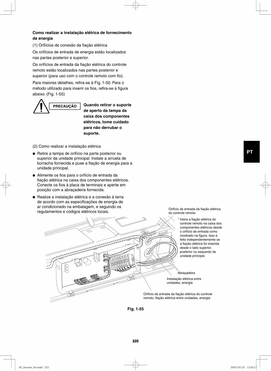
GB
FR
DE
IT
PT
GR
ES
225225
* Insira a fiação elétrica do controle remoto na caixa dos componentes elétricos desde o orifício de entrada como mostrado na figura. Isso é feito independentemente se a fiação elétrica foi inserida desde o lado superior, posterior ou esquerdo da unidade principal.
Orifício de entrada da fiação elétricado controle remoto
Instalação elétrica entre unidades, energia
Orifício de entrada da fiação elétrica do controle remoto, fiação elétrica entre unidades, energia
Abraçadeira
Como realizar a instalação elétrica de fornecimento de energia
(1) Orifícios de conexão da fiação elétrica
Os orifícios de entrada de energia estão localizados nas partes posterior e superior.
Os orifícios de entrada da fiação elétrica do controle remoto estão localizados nas partes posterior e superior (para uso com o controle remoto com fio).
Para maiores detalhes, refira-se à Fig. 1-50. Para o método utilizado para inserir os fios, refira-se à figura abaixo. (Fig. 1-55)
(2) Como realizar a instalação elétrica
● Retire a tampa de orifício na parte posterior ou superior da unidade principal. Instale a arruela de borracha fornecida e puxe a fiação de energia para a unidade principal.
● Alimente os fios para o orifício de entrada da fiação elétrica na caixa dos componentes elétricos. Conecte os fios à placa de terminais e aperte em posição com a abraçadeira fornecida.
● Realize a instalação elétrica e a conexão à terra de acordo com as especificações de energia de ar condicionado na embalagem, e seguindo os regulamentos e códigos elétricos locais.
PRECAUÇÃO Quando retirar o suporte de aperto da tampa da caixa dos componentes elétricos, tome cuidado para não derrubar o suporte.
Fig. 1-55
DC_Inverter_Por.indd 225DC_Inverter_Por.indd 225 2007/07/25 12:20:172007/07/25 12:20:17
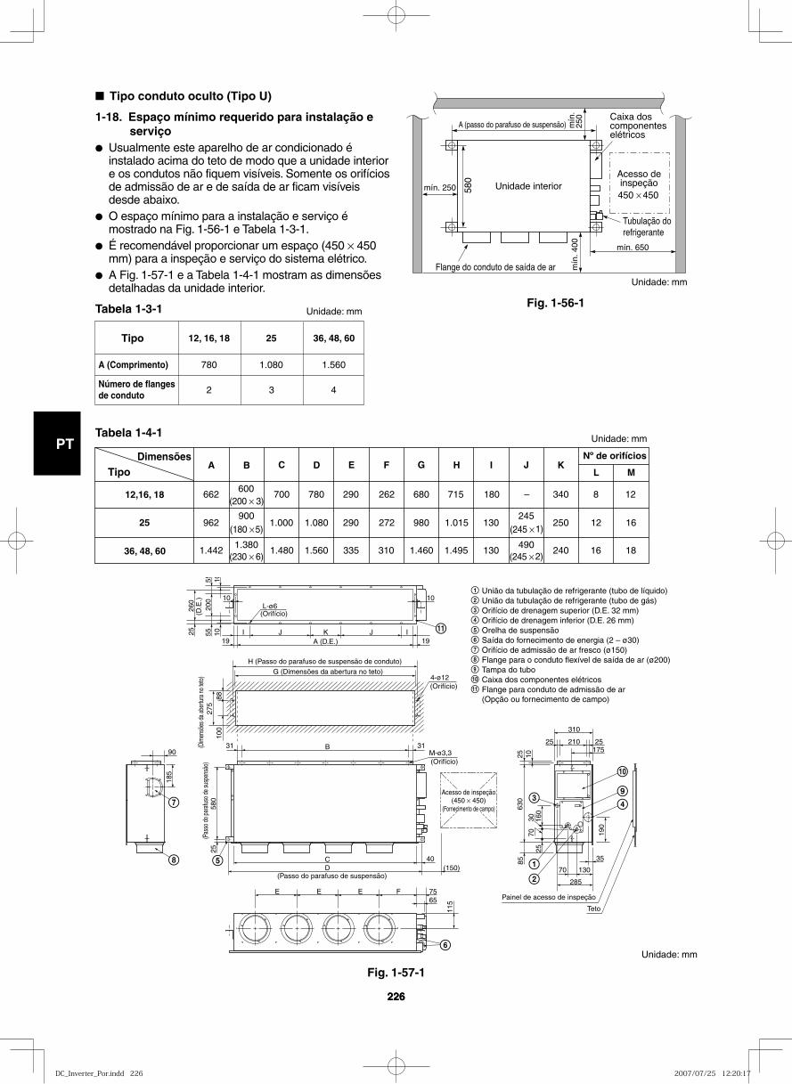
GB
FR
DE
IT
PT
GR
ES
226226
Fig. 1-56-1
Fig. 1-57-1
Unidade interiorAcesso deinspeção450 × 450
Flange do conduto de saída de ar
mín. 250
mín
. 400 mín. 650
580
A (passo do parafuso de suspensão) mín
.25
0 Caixa dos componentes elétricos
Tubulação do refrigerante
■ Tipo conduto oculto (Tipo U)
1-18. Espaço mínimo requerido para instalação e serviço
● Usualmente este aparelho de ar condicionado é instalado acima do teto de modo que a unidade interior e os condutos não fiquem visíveis. Somente os orifícios de admissão de ar e de saída de ar ficam visíveis desde abaixo.
● O espaço mínimo para a instalação e serviço é mostrado na Fig. 1-56-1 e Tabela 1-3-1.
● É recomendável proporcionar um espaço (450 × 450 mm) para a inspeção e serviço do sistema elétrico.
● A Fig. 1-57-1 e a Tabela 1-4-1 mostram as dimensões detalhadas da unidade interior.
Tabela 1-3-1
Tabela 1-4-1
Tipo
A (Comprimento)
Número de flanges de conduto
36, 48, 60
1.560
4
25
1.080
3
12, 16, 18
780
2
DimensõesTipo
12,16, 18
25
36, 48, 60
E F G I J K
662600
700 780 290 262 680 715 180 – 340 8 12(200 × 3)
962900
1.000 1.080 290 272 980 1.015 130245
250 12 16(180 × 5) (245 × 1)
1.4421.380
1.480 1.560 335 310 1.460 1.495 130490
240 16 18(230 × 6) (245 × 2)
Nº de orifícios
L MC DBA H
União da tubulação de refrigerante (tubo de líquido)União da tubulação de refrigerante (tubo de gás)Orifício de drenagem superior (D.E. 32 mm)Orifício de drenagem inferior (D.E. 26 mm)Orelha de suspensãoSaída do fornecimento de energia (2 – ø30)Orifício de admissão de ar fresco (ø150)Flange para o conduto flexível de saída de ar (ø200)Tampa do tuboCaixa dos componentes elétricosFlange para conduto de admissão de ar(Opção ou fornecimento de campo)
9
10
9
10
11
11
(Passo do parafuso de suspensão)
(Pas
so d
o pa
rafu
so d
e su
spen
são)
M-ø3,3(Orifício)
4-ø12(Orifício)
(Orifício)
A (D.E.)
L-ø6
I
10 10
105555
200
10 IJJ K
B
CD (150)
40
E E E F 7565
285
70 130
25 210
310
25175
35
903131
H (Passo do parafuso de suspensão de conduto)G (Dimensões da abertura no teto)
25
100
185
580
25
115
190
85
2570
30 160
630
25 10
8827
5(D
imen
sões
da
aber
tura
no
teto
)26
0(D
.E.)
1919
Acesso de inspeção(450 × 450)
(Fornecimento de campo)
Painel de acesso de inspeção
Teto
Unidade: mm
Unidade: mm
Unidade: mm
Unidade: mm
DC_Inverter_Por.indd 226DC_Inverter_Por.indd 226 2007/07/25 12:20:172007/07/25 12:20:17
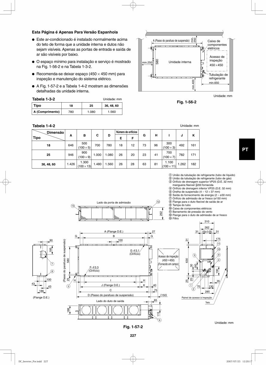
GB
FR
DE
IT
PT
GR
ES
227
Fig. 1-56-2
min.250 580
min
.400
A (Passo do parafuso de suspensão) min
.25
0
Unidade interna
min.650
Caixa decomponenteselétricos
Acesso deinspeção
450 450
Tubulação derefrigerante
Esta Página é Apenas Para Versão Espanhola
● Este ar-condicionado é instalado normalmente acima do teto de forma que a unidade interna e dutos não sejam visíveis. Apenas as portas de entrada e saída de ar são visíveis por baixo.
● O espaço mínimo para instalação e serviço é mostrado na Fig. 1-56-2 e na Tabela 1-3-2.
● Recomenda-se deixar espaço (450 × 450 mm) para inspeção e manutenção do sistema elétrico.
● A Fig. 1-57-2 e a Tabela 1-4-2 mostram as dimensões detalhadas da unidade interna.
Tipo
A (Comprimento)
36, 48, 60
1.560
25
1.080
18
780
DimensãoTipo
18
25
36, 48, 60
E F G H I J K
646 500
700 780 18 12 73 96 492 (100 × 5)
946 900
1.000 1.080 26 20 23 41 782 (100 × 9)
1.4261.300
1.480 1.560 26 28 63 81 1.262
161
171
182 (100 × 13)
300 (100 × 3)
700 (100 × 7)
1.100(100 × 11)
C D B A Número de orifícios
262
100
580
25
H H I (Pas
so d
o pa
rafu
so d
e su
spen
são)
A (Flange D.E.)
Lado da porta de admissão
(Flange D.E.)Lado do duto de saída
J (Flange D.E.)
27
B G G
K 40
C
D (Passo do parafuso de suspensão)
75
(150)
115 18
6
65
90
100
43 43
185
186
310
262
31 100p×2=200 31
35
70 130
175
630
31
25
190
285
160
25
30
Acesso de inspeção(450 450)
(Fornecido em campo)
E- 3.1(Orifício)
F- 3.3(Orifício)
Painel de acesso à inspeção
Teto
1
2
3
4
9
10
11
6
5
7
8
12
13
Unidade: mm
Unidade: mm
Unidade: mm
Unidade: mm
União da tubulação de refrigerante (tubo de líquido)União da tubulação de refrigerante (tubo de gás)Orifício de drenagem superior VP25 (D.E. 32 mm)mangueira flexível 200 fornecidaOrifício de drenagem inferior VP25 (D.E. 32 mm)Orelha de suspensão (4 – 12 × 37 mm)Saída do fornecimento de energia (2 – ø30 mm)Orifício de admissão de ar fresco (ø150 mm)Flange para o duto flexível de saída de arTampa do tubo
Barramento de pressão do ventoFlange para o duto de admissão de ar fresco
11 Caixa de componentes elétricos10
12
Filtro13
Fig. 1-57-2
Tabela 1-4-2
Tabela 1-3-2
DC_Inverter_Por.indd 227DC_Inverter_Por.indd 227 2007/07/25 12:20:172007/07/25 12:20:17
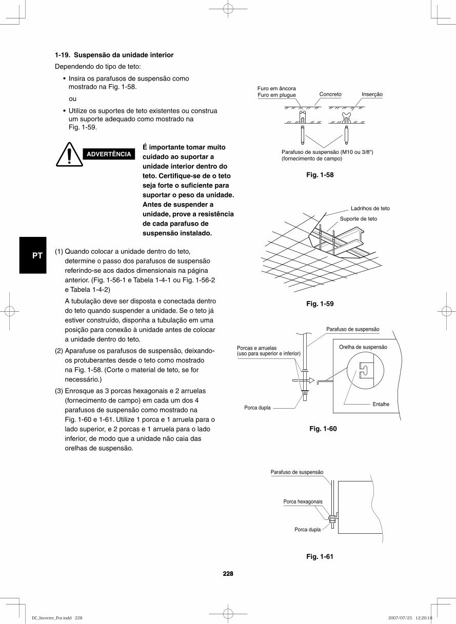
GB
FR
DE
IT
PT
GR
ES
228228
Fig. 1-58
1-19. Suspensão da unidade interior
Dependendo do tipo de teto:
• Insira os parafusos de suspensão como mostrado na Fig. 1-58.
ou
• Utilize os suportes de teto existentes ou construa um suporte adequado como mostrado na Fig. 1-59.
Furo em âncoraFuro em plugue Concreto Inserção
Parafuso de suspensão (M10 ou 3/8")(fornecimento de campo)
Fig. 1-59
Fig. 1-60
Fig. 1-61
Ladrihos de teto
Suporte de teto
Parafuso de suspensão
Orelha de suspensãoPorcas e arruelas(uso para superior e inferior)
EntalhePorca dupla
Porca hexagonais
Parafuso de suspensão
Porca dupla
ADVERTÊNCIAÉ importante tomar muito cuidado ao suportar a unidade interior dentro do teto. Certifique-se de o teto seja forte o suficiente para suportar o peso da unidade. Antes de suspender a unidade, prove a resistência de cada parafuso de suspensão instalado.
(1) Quando colocar a unidade dentro do teto, determine o passo dos parafusos de suspensão referindo-se aos dados dimensionais na página anterior. (Fig. 1-56-1 e Tabela 1-4-1 ou Fig. 1-56-2 e Tabela 1-4-2)
A tubulação deve ser disposta e conectada dentro do teto quando suspender a unidade. Se o teto já estiver construído, disponha a tubulação em uma posição para conexão à unidade antes de colocar a unidade dentro do teto.
(2) Aparafuse os parafusos de suspensão, deixando-os protuberantes desde o teto como mostrado na Fig. 1-58. (Corte o material de teto, se for necessário.)
(3) Enrosque as 3 porcas hexagonais e 2 arruelas (fornecimento de campo) em cada um dos 4 parafusos de suspensão como mostrado na Fig. 1-60 e 1-61. Utilize 1 porca e 1 arruela para o lado superior, e 2 porcas e 1 arruela para o lado inferior, de modo que a unidade não caia das orelhas de suspensão.
DC_Inverter_Por.indd 228DC_Inverter_Por.indd 228 2007/07/25 12:20:182007/07/25 12:20:18
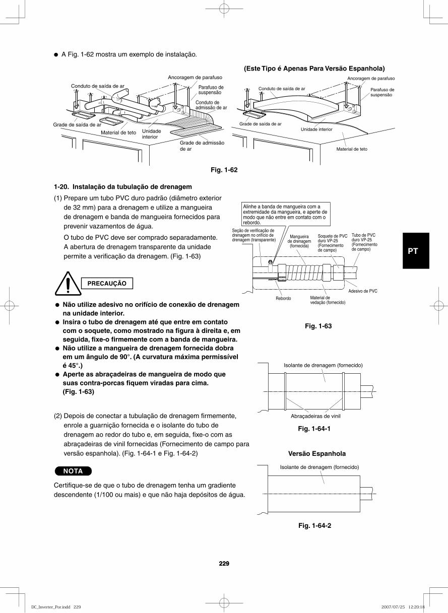
GB
FR
DE
IT
PT
GR
ES
229229
● A Fig. 1-62 mostra um exemplo de instalação.
Conduto de saída de ar
Grade de saída de ar
Material de teto Unidadeinterior
Ancoragem de parafuso
Parafuso desuspensão
Conduto deadmissão de ar
Grade de admissãode ar
Conduto de saída de ar
Grade de saída de ar
Material de teto
Unidade interior
Ancoragem de parafuso
Parafuso desuspensão
(Este Tipo é Apenas Para Versão Espanhola)
Fig. 1-62
Fig. 1-63
Fig. 1-44
Mangueirade drenagem
(fornecida)
Material de vedação (fornecido)
Alinhe a banda de mangueira com a extremidade da mangueira, e aperte de modo que não entre em contato com o rebordo.
Seção de verificação de drenagem no orifício de drenagem (transparente)
Soquete de PVC duro VP-25 (Fornecimento de campo)
Tubo de PVC duro VP-25 (Fornecimento de campo)
Adesivo de PVC
Rebordo
Abraçadeiras de vinil
Isolante de drenagem (fornecido)
1-20. Instalação da tubulação de drenagem
(1) Prepare um tubo PVC duro padrão (diâmetro exterior de 32 mm) para a drenagem e utilize a mangueira de drenagem e banda de mangueira fornecidos para prevenir vazamentos de água.
O tubo de PVC deve ser comprado separadamente. A abertura de drenagem transparente da unidade permite a verificação da drenagem. (Fig. 1-63)
PRECAUÇÃO
● Não utilize adesivo no orifício de conexão de drenagem na unidade interior.
● Insira o tubo de drenagem até que entre em contato com o soquete, como mostrado na figura à direita e, em seguida, fixe-o firmemente com a banda de mangueira.
● Não utilize a mangueira de drenagem fornecida dobra em um ângulo de 90°. (A curvatura máxima permissível é 45°.)
● Aperte as abraçadeiras de mangueira de modo que suas contra-porcas fiquem viradas para cima. (Fig. 1-63)
Fig. 1-64-2
Isolante de drenagem (fornecido)
(2) Depois de conectar a tubulação de drenagem firmemente, enrole a guarnição fornecida e o isolante do tubo de drenagem ao redor do tubo e, em seguida, fixe-o com as abraçadeiras de vinil fornecidas (Fornecimento de campo para versão espanhola). (Fig. 1-64-1 e Fig. 1-64-2)
NOTA
Certifique-se de que o tubo de drenagem tenha um gradiente descendente (1/100 ou mais) e que não haja depósitos de água.
Versão Espanhola
Fig. 1-64-1
DC_Inverter_Por.indd 229DC_Inverter_Por.indd 229 2007/07/25 12:20:182007/07/25 12:20:18
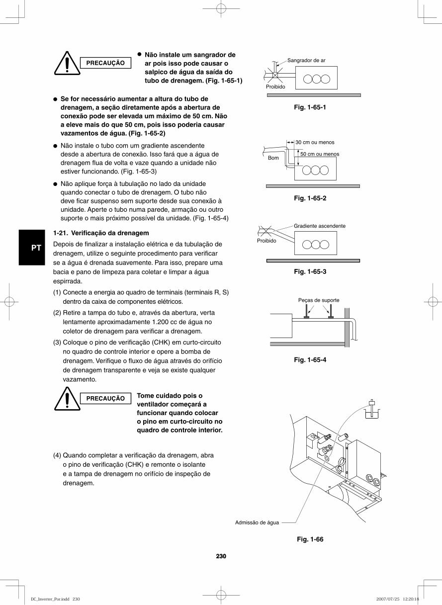
GB
FR
DE
IT
PT
GR
ES
230230
Fig. 1-65-1
Fig. 1-65-2
Fig. 1-65-3
Fig. 1-65-4
Fig. 1-66
Sangrador de ar
Proibido
Bom
30 cm ou menos
50 cm ou menos
Proibido
Gradiente ascendente
Peças de suporte
Admissão de água
● Se for necessário aumentar a altura do tubo de drenagem, a seção diretamente após a abertura de conexão pode ser elevada um máximo de 50 cm. Não a eleve mais do que 50 cm, pois isso poderia causar vazamentos de água. (Fig. 1-65-2)
● Não instale o tubo com um gradiente ascendente desde a abertura de conexão. Isso fará que a água de drenagem flua de volta e vaze quando a unidade não estiver funcionando. (Fig. 1-65-3)
● Não aplique força à tubulação no lado da unidade quando conectar o tubo de drenagem. O tubo não deve ficar suspenso sem suporte desde sua conexão à unidade. Aperte o tubo numa parede, armação ou outro suporte o mais próximo possível da unidade. (Fig. 1-65-4)
1-21. Verificação da drenagem
Depois de finalizar a instalação elétrica e da tubulação de drenagem, utilize o seguinte procedimento para verificar se a água é drenada suavemente. Para isso, prepare uma bacia e pano de limpeza para coletar e limpar a água espirrada.
(1) Conecte a energia ao quadro de terminais (terminais R, S) dentro da caixa de componentes elétricos.
(2) Retire a tampa do tubo e, através da abertura, verta lentamente aproximadamente 1.200 cc de água no coletor de drenagem para verificar a drenagem.
(3) Coloque o pino de verificação (CHK) em curto-circuito no quadro de controle interior e opere a bomba de drenagem. Verifique o fluxo de água através do orifício de drenagem transparente e veja se existe qualquer vazamento.
(4) Quando completar a verificação da drenagem, abra o pino de verificação (CHK) e remonte o isolante e a tampa de drenagem no orifício de inspeção de drenagem.
PRECAUÇÃO
● Não instale um sangrador de ar pois isso pode causar o salpico de água da saída do tubo de drenagem. (Fig. 1-65-1)
PRECAUÇÃO Tome cuidado pois o ventilador começará a funcionar quando colocar o pino em curto-circuito no quadro de controle interior.
DC_Inverter_Por.indd 230DC_Inverter_Por.indd 230 2007/07/25 12:20:182007/07/25 12:20:18

GB
FR
DE
IT
PT
GR
ES
231
(1) Instalação padrãoInstale o filtro sobre a porta de entrada. (Fig. 1-67)
(2) Caso um duto esteja conectado à porta de entrada:
Primeiro remova a cobertura inferior e então instale o filtro dentro da unidade. (Fig. 1-68)
(3) Caso a entrada seja embaixo: Remova a câmara da porta
de entrada da lateral e então recoloque a câmara na parte inferior da unidade. (Fig. 1-69)
Duto de saída
Porta de entrada 2
1
Duto desaídaPorta de
entrada
2
1
Remova a cobertura inferior pararemover ou instalar o filtro.
Filtro
Cobertura inferior
Duto de saída
Porta de entrada2
1
Instale a câmara da porta de entrada na parte inferior.
Filtro
Remova a cobertura inferior e instale-a na lateral.
Fig. 1-67
Fig. 1-68
Fig. 1-69
1-21-2. Instalando o Filtro de Entrada de ar (Esta Página é Apenas Para a Versão Espanhola.)
DC_Inverter_Por.indd 231DC_Inverter_Por.indd 231 2007/07/25 12:20:182007/07/25 12:20:18
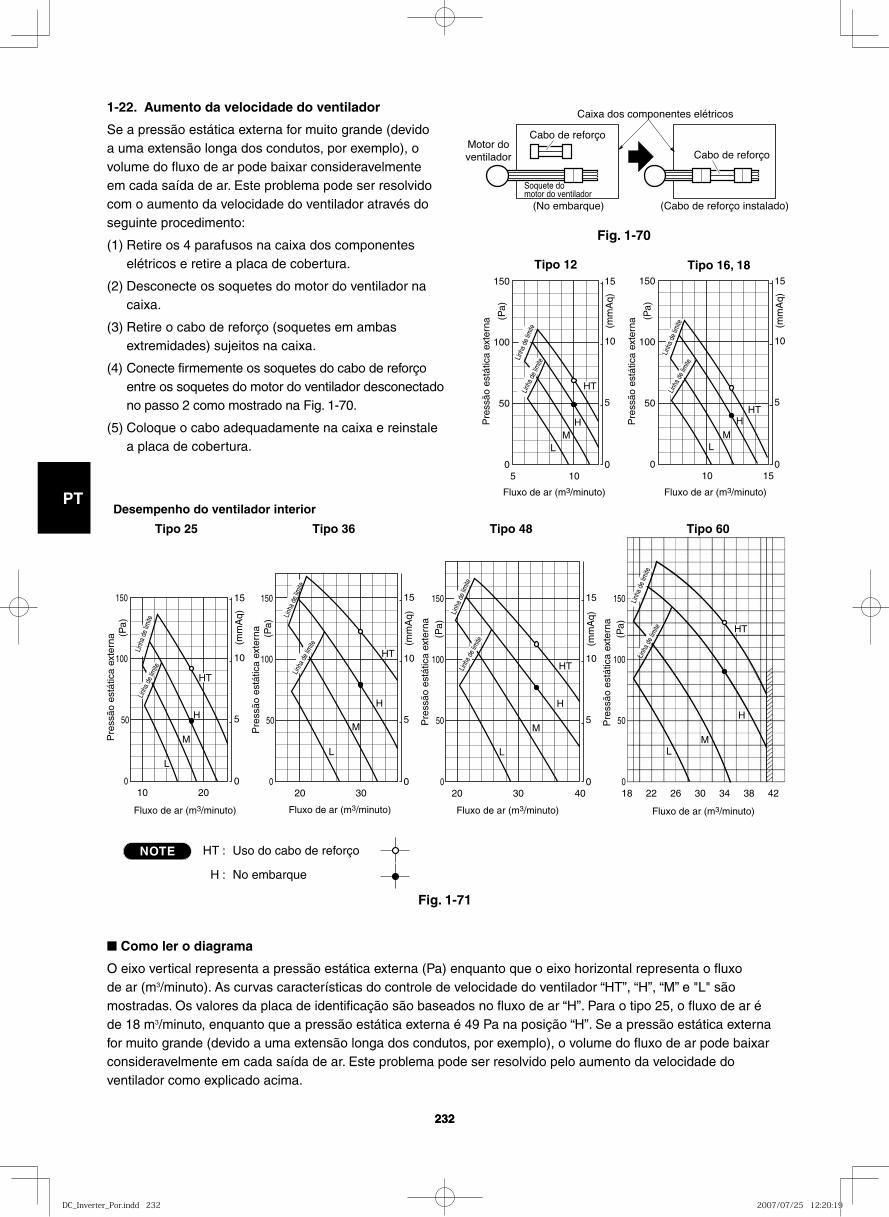
GB
FR
DE
IT
PT
GR
ES
232232
50
50
100
0
5
10
15150
10
(mm
Aq)
(Pa)
HT
HM
L
150
50
0
5
10
15150
10
HT
ML
100
H
(mm
Aq)
(Pa)
200
50
0
5
10
15150
10
HT
H
L
100
M
(mm
Aq)
(Pa)
30 40 18 22 26 30 34 38 420
50
0
5
10
15150
20
L
100
M
H
M
H
L
(mm
Aq)
(Pa)
0
50
150
100
(Pa)
HT
HT
300
50
0
5
10
15150
20
HT
L
100
M
H
(mm
Aq)
(Pa)
HT : Uso do cabo de reforço
H : No embarque
Pre
ssão
est
átic
a ex
tern
a
Linha
de lim
ite
Linha
de
limite
Pre
ssão
est
átic
a ex
tern
a
Linha
de
limite
Linha
de
limite
Pre
ssão
est
átic
a ex
tern
a
Linha
de
limite
Linha
de
limite
Fluxo de ar (m3/minuto) Fluxo de ar (m3/minuto) Fluxo de ar (m3/minuto)
Pre
ssão
est
átic
a ex
tern
a
Linha
de
limite
Linha
de
limite
Fluxo de ar (m3/minuto)
Pre
ssão
est
átic
a ex
tern
a
Linha
de
limite
Linha
de
limite
Fluxo de ar (m3/minuto)
Fluxo de ar (m3/minuto)
Pre
ssão
est
átic
a ex
tern
a
Linha
de
limite
Linh
a de
limite
Tipo 16, 18
Desempenho do ventilador interior
Tipo 25 Tipo 36 Tipo 48
Tipo 12
Tipo 60
NOTE
1-22. Aumento da velocidade do ventilador
Se a pressão estática externa for muito grande (devido a uma extensão longa dos condutos, por exemplo), o volume do fluxo de ar pode baixar consideravelmente em cada saída de ar. Este problema pode ser resolvido com o aumento da velocidade do ventilador através do seguinte procedimento:
(1) Retire os 4 parafusos na caixa dos componentes elétricos e retire a placa de cobertura.
(2) Desconecte os soquetes do motor do ventilador na caixa.
(3) Retire o cabo de reforço (soquetes em ambas extremidades) sujeitos na caixa.
(4) Conecte firmemente os soquetes do cabo de reforço entre os soquetes do motor do ventilador desconectado no passo 2 como mostrado na Fig. 1-70.
(5) Coloque o cabo adequadamente na caixa e reinstale a placa de cobertura.
Fig. 1-70
Fig. 1-71
Cabo de reforço
Cabo de reforço
Caixa dos componentes elétricos
(No embarque) (Cabo de reforço instalado)
Soquete domotor do ventilador
Motor doventilador
■ Como ler o diagrama
O eixo vertical representa a pressão estática externa (Pa) enquanto que o eixo horizontal representa o fluxo de ar (m3/minuto). As curvas características do controle de velocidade do ventilador “HT”, “H”, “M” e "L" são mostradas. Os valores da placa de identificação são baseados no fluxo de ar “H”. Para o tipo 25, o fluxo de ar é de 18 m3/minuto, enquanto que a pressão estática externa é 49 Pa na posição “H”. Se a pressão estática externa for muito grande (devido a uma extensão longa dos condutos, por exemplo), o volume do fluxo de ar pode baixar consideravelmente em cada saída de ar. Este problema pode ser resolvido pelo aumento da velocidade do ventilador como explicado acima.
DC_Inverter_Por.indd 232DC_Inverter_Por.indd 232 2007/07/25 12:20:192007/07/25 12:20:19
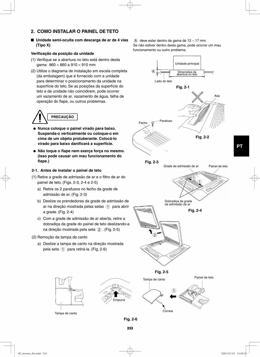
GB
FR
DE
IT
PT
GR
ES
233233
2
Grade de admissão de ar Painel de teto
Dobradiça da grade de admissão de ar
11
2. COMO INSTALAR O PAINEL DE TETO
■ Unidade semi-oculta com descarga de ar de 4 vias (Tipo X)
Verificação da posição da unidade
(1) Verifique se a abertura no teto está dentro desta gama: 860 × 860 a 910 × 910 mm
(2) Utilize o diagrama de instalação em escala completa (da embalagem) que é fornecido com a unidade para determinar o posicionamento da unidade na superfície do teto. Se as posições da superfície do teto e da unidade não coincidirem, pode ocorrer um vazamento de ar, vazamento de água, falha de operação do flape, ou outros problemas.
PRECAUÇÃO
● Nunca coloque o painel virado para baixo. Suspenda-o verticalmente ou coloque-o em cima de um objeto protuberante. Colocá-lo virado para baixo danificará a superfície.
● Não toque o flape nem exerça força no mesmo. (Isso pode causar um mau funcionamento do flape.)
A deve estar dentro da gama de 12 – 17 mm.Se não estiver dentro desta gama, pode ocorrer um mau funcionamento ou outro problema.
Lado do teto
Unidade principal
Dimensões daabertura no teto
A
Fig. 2-1
Asa
Fig. 2-2
Fig. 2-3
Fig. 2-5
2-1. Antes de instalar o painel de teto
(1) Retire a grade de admissão de ar e o filtro de ar do painel de teto. (Figs. 2-3, 2-4 e 2-5)
a) Retire os 2 parafusos no fecho da grade de admissão de ar. (Fig. 2-3)
b) Deslize os prendedores da grade de admissão de ar na direção mostrada pelas setas 1 para abrir a grade. (Fig. 2-4)
c) Com a grade de admissão de ar aberta, retire a dobradiça da grade do painel de teto deslizando-a na direção mostrada pela seta 2 . (Fig. 2-5)
(2) Remoção da tampa de canto
a) Deslize a tampa de canto na direção mostrada pela seta 1 para retirá-la. (Fig. 2-6)
Tampa de canto
Painel de teto
Correia
Empurre
1
Tampa de canto
Fig. 2-6
Fig. 2-4
FechoParafuso
DC_Inverter_Por.indd 233DC_Inverter_Por.indd 233 2007/07/25 12:20:192007/07/25 12:20:19
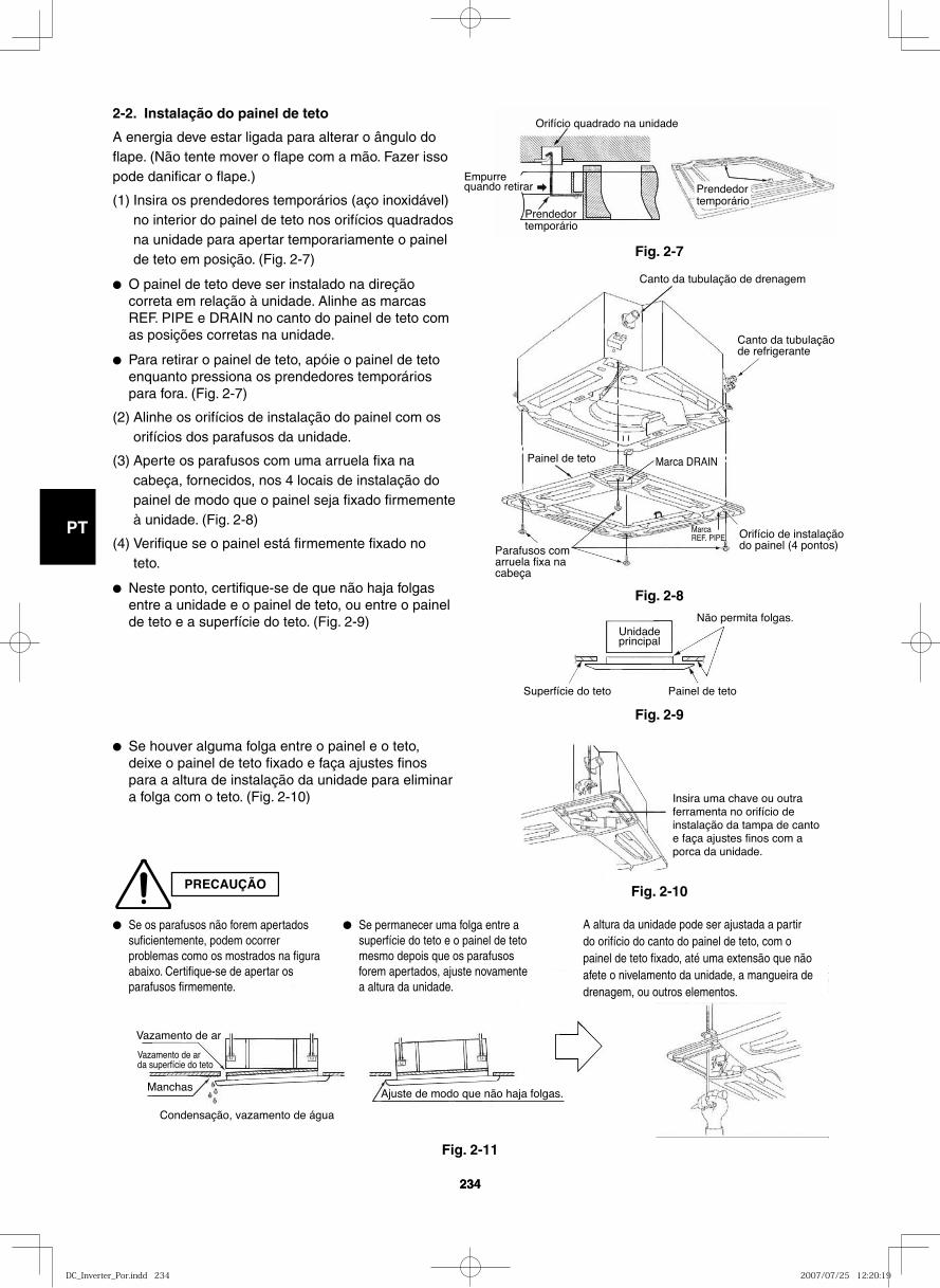
GB
FR
DE
IT
PT
GR
ES
234234
PRECAUÇÃO
2-2. Instalação do painel de teto
A energia deve estar ligada para alterar o ângulo do flape. (Não tente mover o flape com a mão. Fazer isso pode danificar o flape.)
(1) Insira os prendedores temporários (aço inoxidável) no interior do painel de teto nos orifícios quadrados na unidade para apertar temporariamente o painel de teto em posição. (Fig. 2-7)
● O painel de teto deve ser instalado na direção correta em relação à unidade. Alinhe as marcas REF. PIPE e DRAIN no canto do painel de teto com as posições corretas na unidade.
● Para retirar o painel de teto, apóie o painel de teto enquanto pressiona os prendedores temporários para fora. (Fig. 2-7)
(2) Alinhe os orifícios de instalação do painel com os orifícios dos parafusos da unidade.
(3) Aperte os parafusos com uma arruela fixa na cabeça, fornecidos, nos 4 locais de instalação do painel de modo que o painel seja fixado firmemente à unidade. (Fig. 2-8)
(4) Verifique se o painel está firmemente fixado no teto.
● Neste ponto, certifique-se de que não haja folgas entre a unidade e o painel de teto, ou entre o painel de teto e a superfície do teto. (Fig. 2-9)
● Se houver alguma folga entre o painel e o teto, deixe o painel de teto fixado e faça ajustes finos para a altura de instalação da unidade para eliminar a folga com o teto. (Fig. 2-10)
Orifício quadrado na unidade
Prendedor temporário
Empurre quando retirar Prendedor
temporário
Fig. 2-7
Canto da tubulação de drenagem
Canto da tubulação de refrigerante
Orifício de instalação do painel (4 pontos)
Painel de teto
Parafusos com arruela fixa na cabeça
Marca DRAIN
Marca REF. PIPE
Fig. 2-8
Não permita folgas.
Painel de teto
Unidadeprincipal
Superfície do teto
Fig. 2-9
Insira uma chave ou outra ferramenta no orifício de instalação da tampa de canto e faça ajustes finos com a porca da unidade.
Vazamento de ar
Vazamento de arda superfície do teto
Manchas
Condensação, vazamento de água
Ajuste de modo que não haja folgas.
Fig. 2-10
Fig. 2-11
● Se os parafusos não forem apertados suficientemente, podem ocorrer problemas como os mostrados na figura abaixo. Certifique-se de apertar os parafusos firmemente.
● Se permanecer uma folga entre a superfície do teto e o painel de teto mesmo depois que os parafusos forem apertados, ajuste novamente a altura da unidade.
A altura da unidade pode ser ajustada a partir do orifício do canto do painel de teto, com o painel de teto fixado, até uma extensão que não afete o nivelamento da unidade, a mangueira de drenagem, ou outros elementos.
DC_Inverter_Por.indd 234DC_Inverter_Por.indd 234 2007/07/25 12:20:192007/07/25 12:20:19
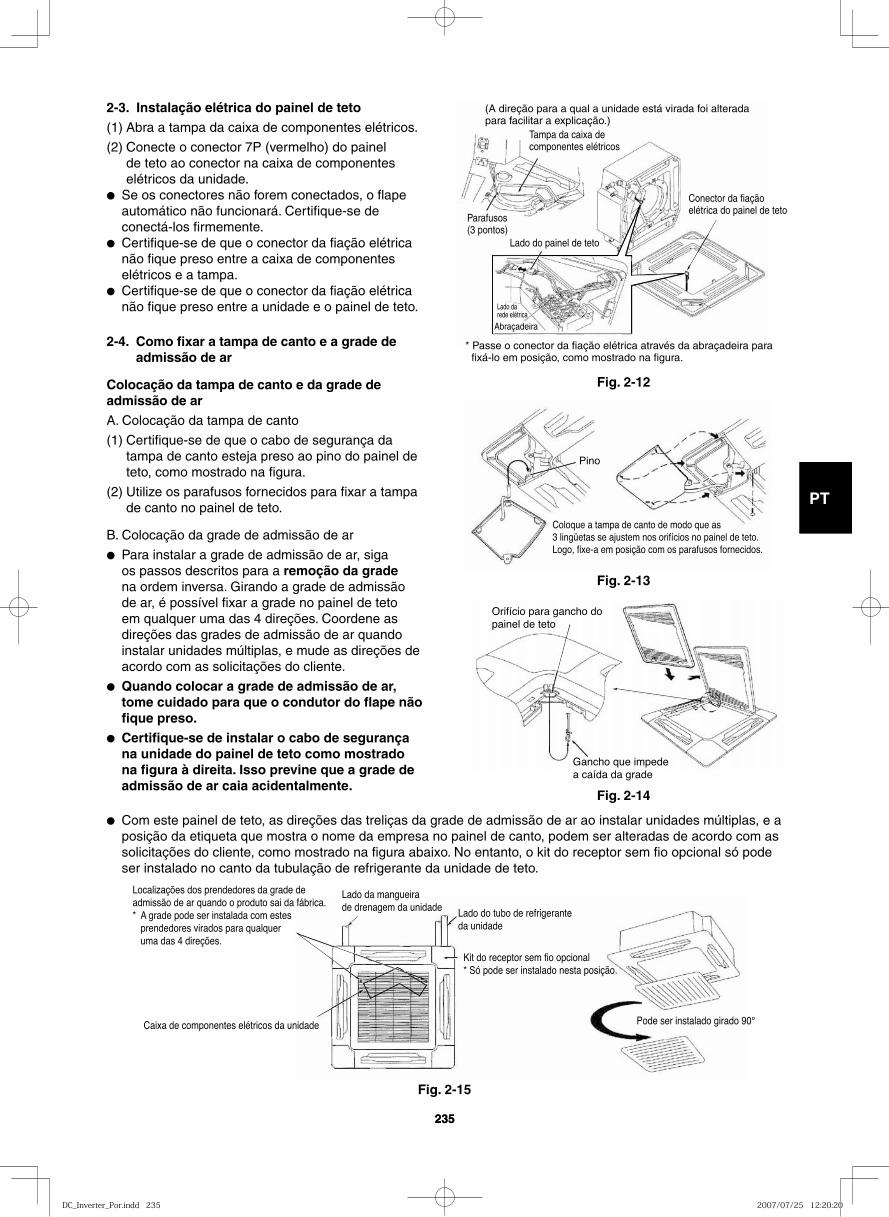
GB
FR
DE
IT
PT
GR
ES
235235
2-3. Instalação elétrica do painel de teto(1) Abra a tampa da caixa de componentes elétricos.
(2) Conecte o conector 7P (vermelho) do painel de teto ao conector na caixa de componentes elétricos da unidade.
● Se os conectores não forem conectados, o flape automático não funcionará. Certifique-se de conectá-los firmemente.
● Certifique-se de que o conector da fiação elétrica não fique preso entre a caixa de componentes elétricos e a tampa.
● Certifique-se de que o conector da fiação elétrica não fique preso entre a unidade e o painel de teto.
2-4. Como fixar a tampa de canto e a grade de admissão de ar
Colocação da tampa de canto e da grade de admissão de arA. Colocação da tampa de canto
(1) Certifique-se de que o cabo de segurança da tampa de canto esteja preso ao pino do painel de teto, como mostrado na figura.
(2) Utilize os parafusos fornecidos para fixar a tampa de canto no painel de teto.
B. Colocação da grade de admissão de ar
● Para instalar a grade de admissão de ar, siga os passos descritos para a remoção da grade na ordem inversa. Girando a grade de admissão de ar, é possível fixar a grade no painel de teto em qualquer uma das 4 direções. Coordene as direções das grades de admissão de ar quando instalar unidades múltiplas, e mude as direções de acordo com as solicitações do cliente.
● Quando colocar a grade de admissão de ar, tome cuidado para que o condutor do flape não fique preso.
● Certifique-se de instalar o cabo de segurança na unidade do painel de teto como mostrado na figura à direita. Isso previne que a grade de admissão de ar caia acidentalmente.
(A direção para a qual a unidade está virada foi alterada para facilitar a explicação.)
Conector da fiaçãoelétrica do painel de teto
Lado do painel de teto
Parafusos(3 pontos)
Abraçadeira
Tampa da caixa de componentes elétricos
* Passe o conector da fiação elétrica através da abraçadeira para fixá-lo em posição, como mostrado na figura.
Lado da rede elétrica
Pino
Coloque a tampa de canto de modo que as 3 lingüetas se ajustem nos orifícios no painel de teto.Logo, fixe-a em posição com os parafusos fornecidos.
● Com este painel de teto, as direções das treliças da grade de admissão de ar ao instalar unidades múltiplas, e a posição da etiqueta que mostra o nome da empresa no painel de canto, podem ser alteradas de acordo com as solicitações do cliente, como mostrado na figura abaixo. No entanto, o kit do receptor sem fio opcional só pode ser instalado no canto da tubulação de refrigerante da unidade de teto.
Caixa de componentes elétricos da unidade
Lado da mangueira de drenagem da unidade Lado do tubo de refrigerante
da unidade
Kit do receptor sem fio opcional* Só pode ser instalado nesta posição.
Pode ser instalado girado 90°
Localizações dos prendedores da grade de admissão de ar quando o produto sai da fábrica.* A grade pode ser instalada com estes
prendedores virados para qualquer uma das 4 direções.
Fig. 2-12
Fig. 2-13
Orifício para gancho dopainel de teto
Gancho que impede a caída da grade
Fig. 2-14
Fig. 2-15
DC_Inverter_Por.indd 235DC_Inverter_Por.indd 235 2007/07/25 12:20:202007/07/25 12:20:20
GB
FR
DE
IT
PT
GR
ES
236236
2-5. Verificação após a instalação
● Certifique-se de que não haja folgas entre a unidade e o painel de teto, ou entre o painel de teto e a superfície do teto.As folgas podem causar vazamento de água e condensação.
● Certifique-se de que a fiação elétrica esteja firmemente conectada. Se não estiver firmemente conectada, o flape automático não funcionará. (“P09” aparece no controle remoto.) Além disso, podem ocorrer vazamentos de água e condensação.
2-6. Quando retirar o painel de teto para serviço
Quando retirar o painel de teto para serviço, retire a grade de admissão de ar e o filtro de ar, desconecte o conector da fiação elétrica dentro da caixa de componentes elétricos e, em seguida, retire os 4 parafusos de montagem.
2-7. Ajuste do flape automático
A persiana de direção do ar na saída do painel de teto pode ser ajustada como segue.
● Ajuste a persiana para o ângulo desejado utilizando o controle remoto. A persiana também tem um mecanismo de varredura automática do ar.
NOTA
● Nunca tente mover a persiana com a mão.
● O fluxo de ar apropriado depende da localização do aparelho de ar condicionado, da disposição do ambiente e móveis, etc. Se a refrigeração ou aquecimento parecerem inadequados, tente mudar a direção do fluxo de ar.
DC_Inverter_Por.indd 236DC_Inverter_Por.indd 236 2007/07/25 12:20:202007/07/25 12:20:20
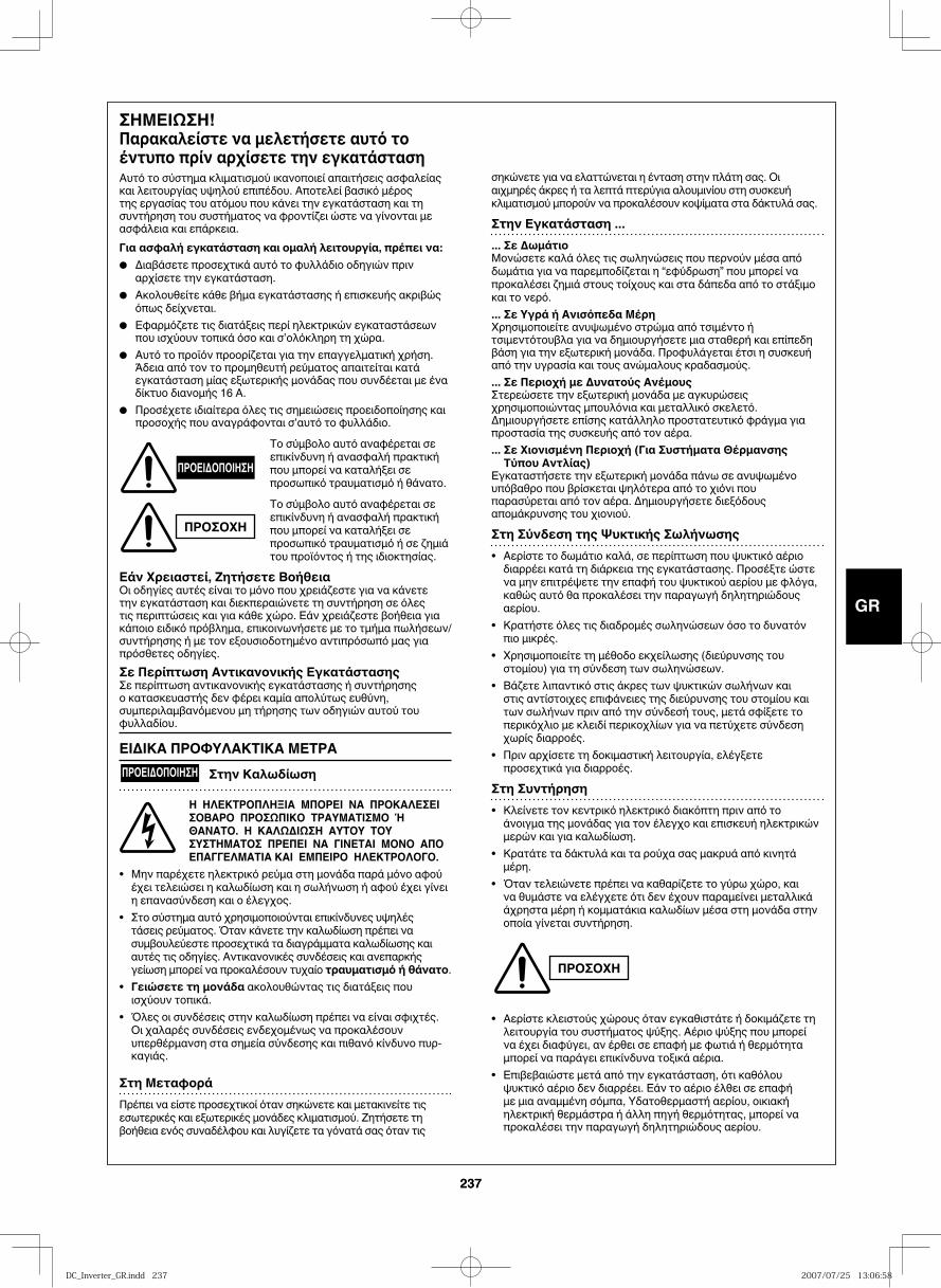
GB
FR
DE
IT
PT
GR
ES
237237
ΣΗΜΕΙΩΣΗ!Παρακαλείστε να μελετήσετε αυτό το έντυπο πρίν αρχίσετε την εγκατάσταση Αυτό το σύστημα κλιματισμού ικανοποιεί απαιτήσεις ασφαλείας και λειτουργίας υψηλού επιπέδου. Αποτελεί βασικό μέρος της εργασίας του ατόμου που κάνει την εγκατάσταση και τη συντήρηση του συστήματος να φροντίζει ώστε να γίνονται με ασφάλεια και επάρκεια.Για ασφαλή εγκατάσταση και ομαλή λειτουργία, πρέπει να:● Διαβάσετε προσεχτικά αυτό το φυλλάδιο οδηγιών πριν
αρχίσετε την εγκατάσταση.● Ακολουθείτε κάθε βήμα εγκατάστασης ή επισκευής ακριβώς
όπως δείχνεται.● Εφαρμόζετε τις διατάξεις περί ηλεκτρικών εγκαταστάσεων
που ισχύουν τοπικά όσο και σ’ολόκληρη τη χώρα.● Αυτό το προϊόν προορίζεται για την επαγγελματική χρήση. Άδεια από τον το προμηθευτή ρεύματος απαιτείται κατά
εγκατάσταση μίας εξωτερικής μονάδας που συνδέεται με ένα δίκτυο διανομής 16 Α.
● Προσέχετε ιδιαίτερα όλες τις σημειώσεις προειδοποίησης και προσοχής που αναγράφονται σ’αυτό το φυλλάδιο.
Το σύμβολο αυτό αναφέρεται σε επικίνδυνη ή ανασφαλή πρακτική που μπορεί να καταλήξει σε προσωπικό τραυματισμό ή θάνατο.
Το σύμβολο αυτό αναφέρεται σε επικίνδυνη ή ανασφαλή πρακτική που μπορεί να καταλήξει σε προσωπικό τραυματισμό ή σε ζημιά του προϊόντος ή της ιδιοκτησίας.
Εάν Χρειαστεί, Ζητήσετε ΒοήθειαΟι οδηγίες αυτές είναι το μόνο που χρειάζεστε για να κάνετε την εγκατάσταση και διεκπεραιώνετε τη συντήρηση σε όλες τις περιπτώσεις και για κάθε χώρο. Εάν χρειάζεστε βοήθεια για κάποιο ειδικό πρόβλημα, επικοινωνήσετε με το τμήμα πωλήσεων/συντήρησης ή με τον εξουσιοδοτημένο αντιπρόσωπό μας για πρόσθετες οδηγίες.Σε Περίπτωση Αντικανονικής ΕγκατάστασηςΣε περίπτωση αντικανονικής εγκατάστασης ή συντήρησης ο κατασκευαστής δεν φέρει καμία απολύτως ευθύνη, συμπεριλαμβανόμενου μη τήρησης των οδηγιών αυτού του φυλλαδίου.
ΕΙΔΙΚΑ ΠΡΟΦΥΛΑΚΤΙΚΑ ΜΕΤΡΑΠΡΟΕΙΔΟΠΟΙΗΣΗ Στην Καλωδίωση
Η ΗΛΕΚΤΡΟΠΛΗΞΙΑ ΜΠΟΡΕΙ ΝΑ ΠΡΟΚΑΛΕΣΕΙ ΣΟΒΑΡΟ ΠΡΟΣΩΠΙΚΟ ΤΡΑΥΜΑΤΙΣΜΟ Ή ΘΑΝΑΤΟ. Η ΚΑΛΩΔΙΩΣΗ ΑΥΤΟΥ ΤΟΥ ΣΥΣΤΗΜΑΤΟΣ ΠΡΕΠΕΙ ΝΑ ΓΙΝΕΤΑΙ ΜΟΝΟ ΑΠΟ ΕΠΑΓΓΕΛΜΑΤΙΑ ΚΑΙ ΕΜΠΕΙΡΟ ΗΛΕΚΤΡΟΛΟΓΟ.
• Μην παρέχετε ηλεκτρικό ρεύμα στη μονάδα παρά μόνο αφού έχει τελειώσει η καλωδίωση και η σωλήνωση ή αφού έχει γίνει η επανασύνδεση και ο έλεγχος.
• Στο σύστημα αυτό χρησιμοποιούνται επικίνδυνες υψηλές τάσεις ρεύματος. Όταν κάνετε την καλωδίωση πρέπει να συμβουλεύεστε προσεχτικά τα διαγράμματα καλωδίωσης και αυτές τις οδηγίες. Αντικανονικές συνδέσεις και ανεπαρκής γείωση μπορεί να προκαλέσουν τυχαίο τραυματισμό ή θάνατο.
• Γειώσετε τη μονάδα ακολουθώντας τις διατάξεις που ισχύουν τοπικά.
• Όλες οι συνδέσεις στην καλωδίωση πρέπει να είναι σφιχτές. Οι χαλαρές συνδέσεις ενδεχομένως να προκαλέσουν υπερθέρμανση στα σημεία σύνδεσης και πιθανό κίνδυνο πυρ-καγιάς.
Στη ΜεταφοράΠρέπει να είστε προσεχτικοί όταν σηκώνετε και μετακινείτε τις εσωτερικές και εξωτερικές μονάδες κλιματισμού. Ζητήσετε τη βοήθεια ενός συναδέλφου και λυγίζετε τα γόνατά σας όταν τις
σηκώνετε για να ελαττώνεται η ένταση στην πλάτη σας. Οι αιχμηρές άκρες ή τα λεπτά πτερύγια αλουμινίου στη συσκευή κλιματισμού μπορούν να προκαλέσουν κοψίματα στα δάκτυλά σας.
Στην Εγκατάσταση ...... Σε ΔωμάτιοΜονώσετε καλά όλες τις σωληνώσεις που περνούν μέσα από δωμάτια για να παρεμποδίζεται η “εφύδρωση” που μπορεί να προκαλέσει ζημιά στους τοίχους και στα δάπεδα από το στάξιμο και το νερό.... Σε Υγρά ή Ανισόπεδα ΜέρηΧρησιμοποιείτε ανυψωμένο στρώμα από τσιμέντο ή τσιμεντότουβλα για να δημιουργήσετε μια σταθερή και επίπεδη βάση για την εξωτερική μονάδα. Προφυλάγεται έτσι η συσκευή από την υγρασία και τους ανώμαλους κραδασμούς.... Σε Περιοχή με Δυνατούς ΑνέμουςΣτερεώσετε την εξωτερική μονάδα με αγκυρώσεις χρησιμοποιώντας μπουλόνια και μεταλλικό σκελετό. Δημιουργήσετε επίσης κατάλληλο προστατευτικό φράγμα για προστασία της συσκευής από τον αέρα.... Σε Χιονισμένη Περιοχή (Για Συστήματα Θέρμανσης Τύπου Αντλίας)
Εγκαταστήσετε την εξωτερική μονάδα πάνω σε ανυψωμένο υπόβαθρο που βρίσκεται ψηλότερα από το χιόνι που παρασύρεται από τον αέρα. Δημιουργήσετε διεξόδους απομάκρυνσης του χιονιού.
Στη Σύνδεση της Ψυκτικής Σωλήνωσης• Αερίστε το δωμάτιο καλά, σε περίπτωση που ψυκτικό αέριο διαρρέει κατά τη διάρκεια της εγκατάστασης. Προσέξτε ώστε να μην επιτρέψετε την επαφή του ψυκτικού αερίου με φλόγα, καθώς αυτό θα προκαλέσει την παραγωγή δηλητηριώδους αερίου.
• Κρατήστε όλες τις διαδρομές σωληνώσεων όσο το δυνατόν πιο μικρές.
• Χρησιμοποιείτε τη μέθοδο εκχείλωσης (διεύρυνσης του στομίου) για τη σύνδεση των σωληνώσεων.
• Βάζετε λιπαντικό στις άκρες των ψυκτικών σωλήνων και στις αντίστοιχες επιφάνειες της διεύρυνσης του στομίου και των σωλήνων πριν από την σύνδεσή τους, μετά σφίξετε το περικόχλιο με κλειδί περικοχλίων για να πετύχετε σύνδεση χωρίς διαρροές.
• Πριν αρχίσετε τη δοκιμαστική λειτουργία, ελέγξετε προσεχτικά για διαρροές.
Στη Συντήρηση• Κλείνετε τον κεντρικό ηλεκτρικό διακόπτη πριν από το άνοιγμα της μονάδας για τον έλεγχο και επισκευή ηλεκτρικών μερών και για καλωδίωση.
• Κρατάτε τα δάκτυλά και τα ρούχα σας μακρυά από κινητά μέρη.
• Όταν τελειώνετε πρέπει να καθαρίζετε το γύρω χώρο, και να θυμάστε να ελέγχετε ότι δεν έχουν παραμείνει μεταλλικά άχρηστα μέρη ή κομματάκια καλωδίων μέσα στη μονάδα στην οποία γίνεται συντήρηση.
• Aερίστε κλειστούς χώρους όταν εγκαθιστάτε ή δοκιμάζετε τη λειτουργία του συστήματος ψύξης. Aέριο ψύξης που μπορεί να έχει διαφύγει, αν έρθει σε επαφή με φωτιά ή θερμότητα μπορεί να παράγει επικίνδυνα τοξικά αέρια.
• Επιβεβαιώστε μετά από την εγκατάσταση, ότι καθόλου ψυκτικό αέριο δεν διαρρέει. Εάν το αέριο έλθει σε επαφή με μια αναμμένη σόμπα, Υδατοθερμαστή αερίου, οικιακή ηλεκτρική θερμάστρα ή άλλη πηγή θερμότητας, μπορεί να προκαλέσει την παραγωγή δηλητηριώδους αερίου.
ΠΡΟΕΙΔΟΠΟΙΗΣΗ
ΠΡΟΣΟΧΗ
ΠΡΟΣΟΧΗ
DC_Inverter_GR.indd 237DC_Inverter_GR.indd 237 2007/07/25 13:06:582007/07/25 13:06:58
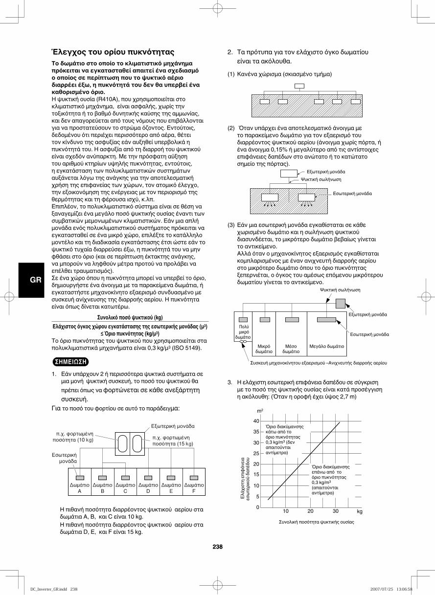
GB
FR
DE
IT
PT
GR
ES
238238
Έλεγχος του ορίου πυκνότηταςΤο δωμάτιο στο οποίο το κλιματιστικό μηχάνημα πρόκειται να εγκατασταθεί απαιτεί ένα σχεδιασμό ο οποίος σε περίπτωση που το ψυκτικό αέριο διαρρέει έξω, η πυκνότητά του δεν θα υπερβεί ένα καθορισμένο όριο.Η ψυκτική ουσία (R410A), που χρησιμοποιείται στο κλιματιστικό μηχάνημα, είναι ασφαλής, χωρίς την τοξικότητα ή το βαθμό δυνητικής καύσης της αμμωνίας, και δεν απαγορεύεται από τους νόμους που επιβάλλονται για να προστατεύσουν το στρώμα όζοντος. Εντούτοις, δεδομένου ότι περιέχει περισσότερο από αέρα, θέτει τον κίνδυνο της ασφυξίας εάν αυξηθεί υπερβολικά η πυκνότητά του. Η ασφυξία από τη διαρροή του ψυκτικού είναι σχεδόν ανύπαρκτη. Με την πρόσφατη αύξηση του αριθμού κτηρίων υψηλής πυκνότητας, εντούτοις, η εγκατάσταση των πολυκλιματιστικών συστημάτων αυξάνεται λόγω της ανάγκης για την αποτελεσματική χρήση της επιφανείας των χώρων, τον ατομικό έλεγχο, την εξοικονόμηση της ενέργειας με τον περιορισμό της θερμότητας και τη φέρουσα ισχύ, κ.λπ. Επιπλέον, το πολυκλιματιστικό σύστημα είναι σε θέση να ξαναγεμίζει ένα μεγάλο ποσό ψυκτικής ουσίας έναντι των συμβατικών μεμονωμένων κλιματιστικών. Εάν μια απλή μονάδα ενός πολυκλιματιστικού συστήματος πρόκειται να εγκατασταθεί σε ένα μικρό χώρο, επιλέξτε το κατάλληλο μοντέλο και τη διαδικασία εγκατάστασης έτσι ώστε εάν το ψυκτικό τυχαία διαρρεύσει έξω, η πυκνότητά του να μην φθάσει στο όριο (και σε περίπτωση έκτακτης ανάγκης, να μπορούν να ληφθούν μέτρα προτού να προλάβει να επέλθει τραυματισμός). Σε ένα χώρο όπου η πυκνότητα μπορεί να υπερβεί το όριο, δημιουργήστε ένα άνοιγμα με τα παρακείμενα δωμάτια, ή εγκαταστήστε μηχανοκίνητο εξαερισμό συνδυασμένο με συσκευή ανίχνευσης της διαρροής αερίου. Η πυκνότητα είναι όπως δίνεται κατωτέρω.
Συνολικό ποσό ψυκτικού (kg)Ελάχιστος όγκος χώρου εγκατάστασης της εσωτερικής μονάδας (μ3)
≤ Όριο πυκνότητας (kg/μ3)Το όριο πυκνότητας του ψυκτικού που χρησιμοποιείται στα πολυκλιματιστικά μηχανήματα είναι 0,3 kg/μ3 (ISO 5149).
ΣΗΜΕΙΩΣΗ1. Εάν υπάρχουν 2 ή περισσότερα ψυκτικά συστήματα σε
μια μονή ψυκτική συσκευή, το ποσό του ψυκτικού θα πρέπει όπως να φορτώνεται σε κάθε ανεξάρτητη συσκευή.
Για το ποσό του φορτίου σε αυτό το παράδειγμα:
Η πιθανή ποσότητα διαρρέοντος ψυκτικού αερίου στα δωμάτια Α, Β, και C είναι 10 kg. Η πιθανή ποσότητα διαρρέοντος ψυκτικού αερίου στα δωμάτια D, Ε, και F είναι 15 kg.
2. Τα πρότυπα για τον ελάχιστο όγκο δωματίου είναι τα ακόλουθα.
(1) Κανένα χώρισμα (σκιασμένο τμήμα)
(2) Όταν υπάρχει ένα αποτελεσματικό άνοιγμα με το παρακείμενο δωμάτιο για τον εξαερισμό του διαρρέοντος ψυκτικού αερίου (άνοιγμα χωρίς πόρτα, ή ένα άνοιγμα 0,15% ή μεγαλύτερο από τις αντίστοιχες επιφάνειες δαπέδων στο ανώτατο ή το κατώτατο σημείο της πόρτας).
(3) Εάν μια εσωτερική μονάδα εγκαθίσταται σε κάθε χωρισμένο δωμάτιο και η σωλήνωση ψυκτικού διασυνδέεται, το μικρότερο δωμάτιο βεβαίως γίνεται το αντικείμενο.
Αλλά όταν ο μηχανοκίνητος εξαερισμός εγκαθίσταται κομπλαρισμένος με έναν ανιχνευτή διαρροής αερίου στο μικρότερο δωμάτιο όπου το όριο πυκνότητας ξεπερνιέται, ο όγκος του αμέσως επόμενου μικρότερου δωματίου γίνεται το αντικείμενο.
3. Η ελάχιστη εσωτερική επιφάνεια δαπέδου σε σύγκριση με το ποσό της ψυκτικής ουσίας είναι κατά προσέγγιση η ακόλουθη: (Όταν η οροφή έχει ύψος 2,7 m)
40
35
30
25
20
15
10
5
010 20 30
m2
kg
Εξωτερική μονάδα
Εξωτερική μονάδα
Ψυκτική σωλήνωση
Ψυκτική σωλήνωση
Εσωτερική μονάδα
Εσωτερική μονάδα
Ελάχιστη
επιφάνεια
εσωτερικού δαπέδου
Όριο διακύμανσης κάτω από το όριο πυκνότητας 0,3 kg/m3 (δεν απαιτούνται αντίμετρα)
Όριο διακύμανσης επάνω από το όριο πυκνότητας 0,3 kg/m3 (απαιτούνται αντίμετρα)
Συσκευή μηχανοκίνητου εξαερισμού –Ανιχνευτής διαρροής αερίου
Συνολική ποσότητα ψυκτικής ουσίας
Μεγάλο δωμάτιοΜέσο δωμάτιο
Μικρό δωμάτιο
Πολύ μικρό
δωμάτιο
DC_Inverter_GR.indd 238DC_Inverter_GR.indd 238 2007/07/25 13:06:582007/07/25 13:06:58
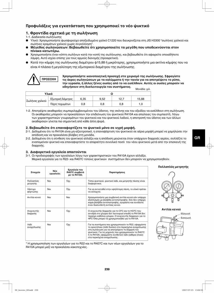
GB
FR
DE
IT
PT
GR
ES
239239
Χρησιμοποιήστε ικανοποιητική προσοχή στο χειρισμό της σωλήνωσης. Σφραγίστε τις άκρες σωληνώσεων με τα καλύμματα ή την ταινία για να αποτρέψετε το ρύπο, την υγρασία, ή άλλες ξένες ουσίες από το να εισέλθουν. Αυτές οι ουσίες μπορούν να οδηγήσουν στη δυσλειτουργία του συστήματος.
1-2. Αποτρέψτε ακαθαρσίες συμπεριλαμβανομένου του ύδατος, της σκόνης και του οξειδίου να εισέλθουν στη σωλήνωση. Οι ακαθαρσίες μπορούν να προκαλέσουν την επιδείνωση του ψυκτικού R410A και απώλειες του συμπιεστή. Λόγω των χαρακτηριστικών γνωρισμάτων του ψυκτικού και του ψυκτικού λαδιού, η αποτροπή του ύδατος και των άλλων ακαθαρσιών γίνεται πιο σημαντική από κάθε άλλη φορά.
2. Βεβαιωθείτε ότι επαναφορτίζετε το ψυκτικό μόνο σε υγρή μορφή. 2-1. Δεδομένου ότι το R410A είναι μη-αζεοτροπικό, η επαναφόρτιση του ψυκτικού σε αέρια μορφή μπορεί να χαμηλώσει την
απόδοση και να προκαλέσει βλάβες στη μονάδα. 2-2. Δεδομένου ότι η σύνθεση του ψυκτικού αλλάζει και η απόδοση μειώνεται όταν υπάρχουν διαρροές αερίου, συλλέξτε το
εναπομείναν ψυκτικό και επαναφορτίστε το απαραίτητο συνολικό ποσό του νέου ψυκτικού μετά από την επισκευή της διαρροής.
3. Διαφορετικά εργαλεία απαιτούνται 3-1. Οι προδιαγραφές των εργαλείων λόγω των χαρακτηριστικών του R410A έχουν αλλάξει.
Μερικά εργαλεία για το R22- και R407C τύπους ψυκτικών συστημάτων δεν μπορούν να χρησιμοποιηθούν.
Μονάδα: χιλ.
Υλικό O
Σωλήνας χαλκού Εξωτερική διάμετρος 6,35 9,52 12,7 15,88 Πάχος τοιχωμάτων 0,8 0,8 0,8 1,0
Προφυλάξεις για εγκατάσταση που χρησιμοποιεί το νέο ψυκτικό
1. Φροντίδα σχετικά με τη σωλήνωση1-1. Διαδικασία σωλήνωσης● Υλικό: Χρησιμοποιήστε φωσφορούχο αποξειδωμένο χαλκό C1220 που διευκρινίζεται στη JIS H3300 “σωλήνες χαλκού και
σωλήνες κραμάτων χαλκού χωρίς συγκόλληση”.● Μέγεθος σωληνώσεων: Βεβαιωθείτε ότι χρησιμοποιείτε τα μεγέθη που υποδεικνύονται στον
πίνακα κατωτέρω. ● Χρησιμοποιήστε έναν κόπτη σωλήνων κατά την κοπή της σωλήνωσης, και βεβαιωθείτε ότι αφαιρείτε οποιαδήποτε
λάμψη. Αυτό ισχύει επίσης για τους αρμούς διανομής (προαιρετικό). ● Κατά την κάμψη της σωλήνωσης διαμέτρου φ15,88 ή μικρότερης, χρησιμοποιήστε μια ακτίνα κάμψης που να
είναι 4 πλάσια ή μεγαλύτερη της εξωτερικού διαμέτρου της σωλήνωσης.
* Η χρησιμοποίηση των εργαλείων για το R22 και το R407C και των νέων εργαλείων για το R410A μπορεί μαζί να προκαλέσει κακοτεχνίες.
ΠΡΟΣΟΧΗ
Πολλαπλός μετρητής
Αντλία κενούΕξαγωγή
Εισαγωγή
Στοιχείο Νέο εργαλείο;
Εργαλεία του R407C συμβατά με το R410A;
Παρατηρήσεις
Πολλαπλός μετρητής
Ναι Όχι Τύποι ψυκτικού, ψυκτικό λάδι, και μετρητής πίεσης είναι διαφορετικοί.
Λάστιχο φόρτωσης
Ναι Όχι Για να αντισταθεί στην υψηλότερη πίεση, το υλικό πρέπει να αλλαχτεί.
Αντλία κενού Ναι Ναι Χρησιμοποιήστε μια συμβατική αντλία κενού εάν υπάρχει εξοπλισμός με βαλβίδα αντεπιστροφής. Εάν δεν υπάρχει καμία βαλβίδα αντεπιστροφής, αγοράστε και συνδέστε έναν διασυνδετή αντλίας κενού.
Ανιχνευτής διαρροής
Ναι Όχι Ο ανιχνευτής διαρροής για το CFC και το HCFC που αντιδρά στο χλώριο δεν λειτουργεί επειδή το R410A δεν περιέχει καθόλου χλώριο. Ο ανιχνευτής διαρροών για το HFC134a μπορεί να χρησιμοποιηθεί για το R410A.
Λάδι αναχείλωσης
Ναι Όχι Για τα συστήματα που χρησιμοποιούν το R22, εφαρμόστε το ορυκτέλαιο (λάδι Suniso) στα περικόχλια αναχείλωσης στη σωλήνωση για να αποτρέψετε τη διαρροή του ψυκτικού. Για τις μηχανές που χρησιμοποιούν το R407C ή το R410A, εφαρμόστε συνθετικό λάδι (αιθέριο έλαιο) στα περικόχλια αναχείλωσης.
DC_Inverter_GR.indd 239DC_Inverter_GR.indd 239 2007/07/25 13:06:592007/07/25 13:06:59
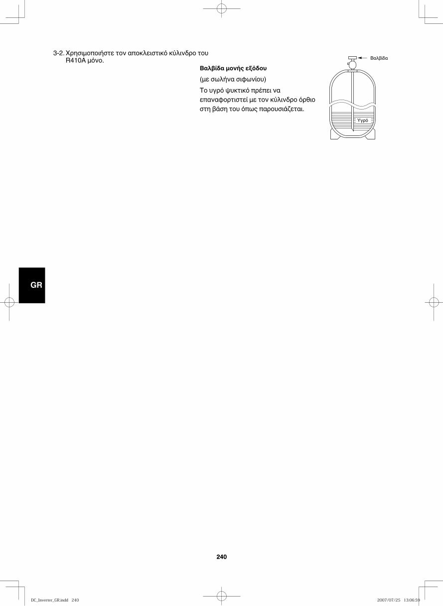
GB
FR
DE
IT
PT
GR
ES
240240
3-2. Χρησιμοποιήστε τον αποκλειστικό κύλινδρο του R410A μόνο.
Βαλβίδα μονής εξόδου
(με σωλήνα σιφωνίου) Το υγρό ψυκτικό πρέπει να επαναφορτιστεί με τον κύλινδρο όρθιο στη βάση του όπως παρουσιάζεται.
Βαλβίδα
Yγρό
DC_Inverter_GR.indd 240DC_Inverter_GR.indd 240 2007/07/25 13:06:592007/07/25 13:06:59
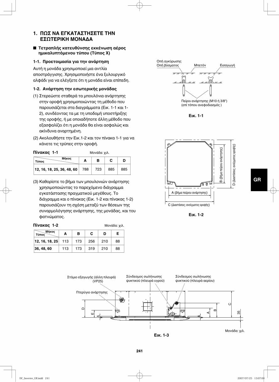
GB
FR
DE
IT
PT
GR
ES
241241
1. ΠΩΣ ΝΑ ΕΓΚΑΤΑΣΤΗΣΕΤΕ ΤΗΝ ΕΣΩΤΕΡΙΚΗ ΜΟΝΑΔΑ
■ Τετραπλής κατευθύνσης εκκένωση αέρος ημικαλυπτόμενου τύπου (Τύπος X)
1-1. Προετοιμασία για την ανάρτησηΑυτή η μονάδα χρησιμοποιεί μια αντλία αποστράγγισης. Χρησιμοποιήστε ένα ξυλουργικό αλφάδι για να ελέγξετε ότι η μονάδα είναι επίπεδη.
1-2. Aνάρτηση την εσωτερικής μονάδας(1) Στερεώστε σταθερά τα μπουλόνια ανάρτησης
στην οροφή χρησιμοποιώντας τη μέθοδο που παρουσιάζεται στα διαγράμματα (Εικ. 1-1 και 1-2), συνδέοντας τα με τη υποδομή υποστήριξης της οροφής, ή με οποιαδήποτε άλλη μέθοδο που εξασφαλίζει ότι η μονάδα θα είναι ασφαλώς και ακίνδυνα αναρτημένη.
(2) Ακολουθήστε την Εικ.1-2 και τον πίνακα 1-1 για να κάνετε τις τρύπες στην οροφή.
Πίνακας 1-1 Μονάδα: χιλ.
(3) Καθορίστε το βήμα των μπουλονιών ανάρτησης χρησιμοποιώντας το παρεχόμενο διάγραμμα εγκατάστασης πραγματικού μεγέθους. Το διάγραμμα και ο πίνακας (Εικ. 1-2 και πίνακας 1-2) παρουσιάζουν τη σχέση μεταξύ των θέσεων της συναρμολόγησης ανάρτησης, της μονάδας, και του φατνώματος.
Πίνακας 1-2 Μονάδα: χιλ.
Εικ. 1-1
Εικ. 1-2
Εικ. 1-3
Οπή αγκύρωσηςΟπή βύσματος Μπετόν Εισαγωγή
Πείροι ανάρτησης (Μ10 ή 3/8")(επί τόπου ανεφοδιασμός )
Τύπος A B C D
788 723 88588512, 16, 18, 25, 36, 48, 60
Μήκος
A B C D113 173
173210210
25636, 48, 6012, 16, 18, 25
E8888319113
ΤύποςΜήκος
D (Δι
αστάσε
ις; ανο
ίγματο
ς οροφ
ής)
C (Διαστάσεις; ανοίγματος οροφής)
A (βήμα πείρου ανάρτησης)
B (βή
μα πε
ίρου α
νάρτη
σης)
E A
B
C
D
35
Πτερύγιο ανάρτησης
Σύνδεσμος σωλήνωσης ψυκτικού (πλευρά υγρού)
Σύνδεσμος σωλήνωσης ψυκτικού (πλευρά αερίου)(VP25)
Στόμιο εξαγωγής (άλλη πλευρά)
Μονάδα: χιλ.
DC_Inverter_GR.indd 241DC_Inverter_GR.indd 241 2007/07/25 13:07:002007/07/25 13:07:00
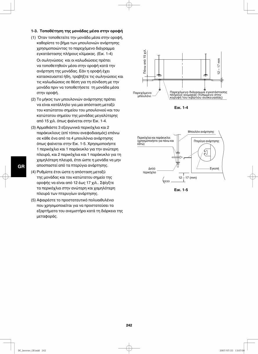
GB
FR
DE
IT
PT
GR
ES
242242
Εικ. 1-4
Εικ. 1-5
1-3. Τοποθέτηση της μονάδας μέσα στην οροφή(1) Όταν τοποθετείτε την μονάδα μέσα στην οροφή,
καθορίστε το βήμα των μπουλονιών ανάρτησης χρησιμοποιώντας το παρεχόμενο διάγραμμα εγκατάστασης πλήρους κλίμακας. (Εικ. 1-4)
Οι σωληνώσεις και οι καλωδιώσεις πρέπει να τοποθετηθούν μέσα στην οροφή κατά την ανάρτηση της μονάδας. Εάν η οροφή έχει κατασκευαστεί ήδη, τραβήξτε τις σωληνώσεις και τις καλωδιώσεις σε θέση για τη σύνδεση με την μονάδα πριν να τοποθετήσετε τη μονάδα μέσα στην οροφή.
(2) Το μήκος των μπουλονιών ανάρτησης πρέπει να είναι κατάλληλο για μια απόσταση μεταξύ του κατώτατου σημείου του μπουλονιού και του κατώτατου σημείου της μονάδας μεγαλύτερης από 15 χιλ. όπως φαίνεται στην Εικ. 1-4.
(3) Αρμαθιάστε 3 εξαγωνικά περικόχλια και 2 παράκυκλους (επί τόπου ανεφοδιασμός) επάνω σε κάθε ένα από τα 4 μπουλόνια ανάρτησης όπως φαίνεται στην Εικ. 1-5. Χρησιμοποιήστε 1 περικόχλιο και 1 παράκυκλο για την ανώτερη πλευρά, και 2 περικόχλια και 1 παράκυκλο για τη χαμηλότερη πλευρά, έτσι ώστε η μονάδα να μην αποσπαστεί από τα πτερύγια ανάρτησης.
(4) Ρυθμίστε έτσι ώστε η απόσταση μεταξύ της μονάδας και του κατώτατου σημείο της οροφής να είναι από 12 έως 17 χιλ.. Σφίγξτε τα περικόχλια στην ανώτερη και χαμηλότερη πλευρά των πτερυγίων ανάρτησης.
(5) Αφαιρέστε το προστατευτικό πολυαιθυλένιο που χρησιμοποιείται για να προστατεύσει τα εξαρτήματα του ανεμιστήρα κατά τη διάρκεια της μεταφοράς.
12 –
17
mm
12 – 17 (mm)
Μπουλόνι ανάρτησης
Πτερύγιο ανάρτησηςΠερικόχλια και παράκυκλοι (χρησιμοποιήστε για πάνω και κάτω)
ΕγκοπήΔιπλό περικόχλιο
DC_Inverter_GR.indd 242DC_Inverter_GR.indd 242 2007/07/25 13:07:002007/07/25 13:07:00
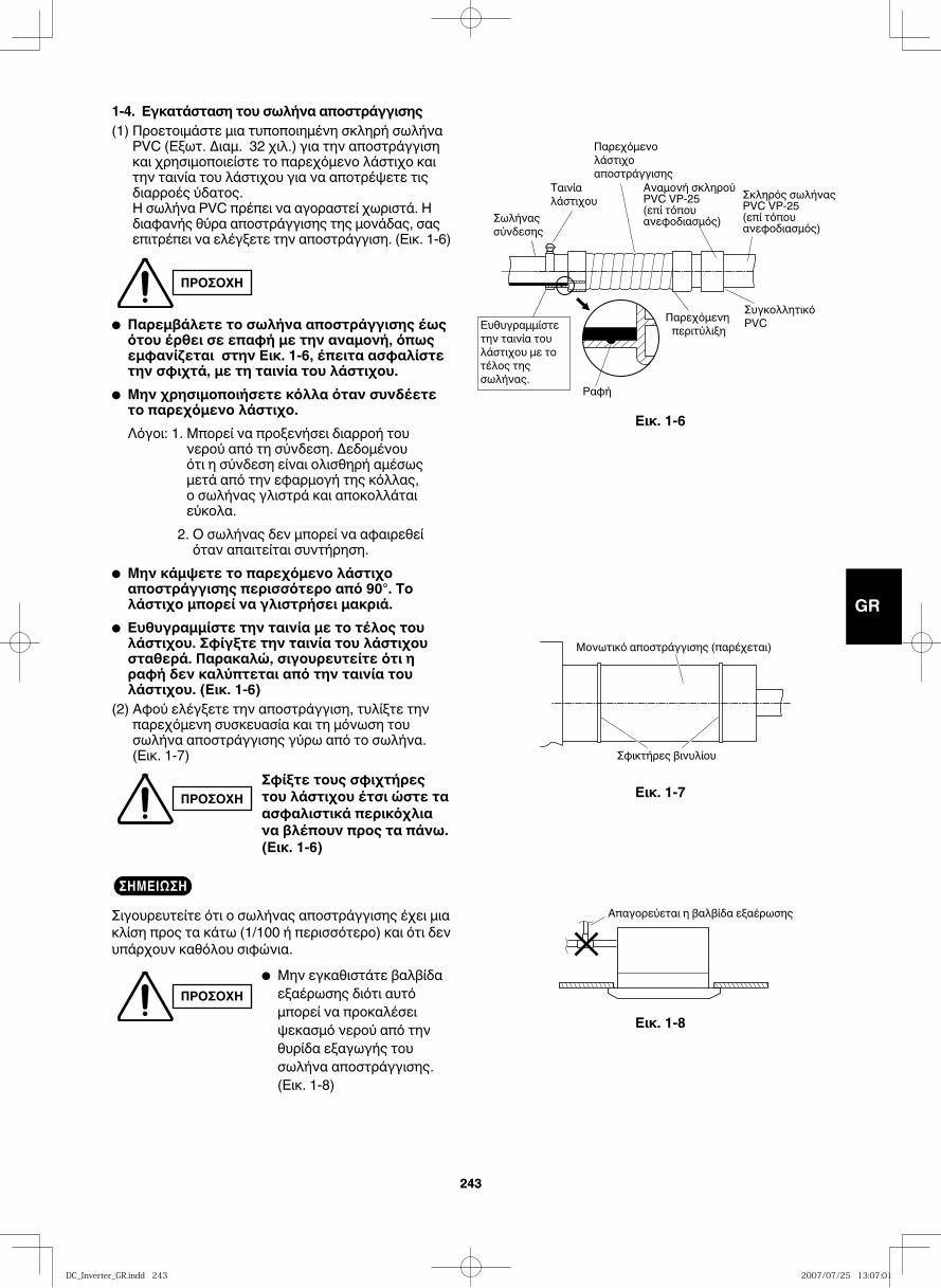
GB
FR
DE
IT
PT
GR
ES
243243
1-4. Εγκατάσταση του σωλήνα αποστράγγισης (1) Προετοιμάστε μια τυποποιημένη σκληρή σωλήνα
PVC (Εξωτ. Διαμ. 32 χιλ.) για την αποστράγγιση και χρησιμοποιείστε το παρεχόμενο λάστιχο και την ταινία του λάστιχου για να αποτρέψετε τις διαρροές ύδατος. Η σωλήνα PVC πρέπει να αγοραστεί χωριστά. Η διαφανής θύρα αποστράγγισης της μονάδας, σας επιτρέπει να ελέγξετε την αποστράγγιση. (Εικ. 1-6)
● Παρεμβάλετε το σωλήνα αποστράγγισης έως ότου έρθει σε επαφή με την αναμονή, όπως εμφανίζεται στην Εικ. 1-6, έπειτα ασφαλίστε την σφιχτά, με τη ταινία του λάστιχου.
● Μην χρησιμοποιήσετε κόλλα όταν συνδέετε το παρεχόμενο λάστιχο.
Λόγοι: 1. Μπορεί να προξενήσει διαρροή του νερού από τη σύνδεση. Δεδομένου ότι η σύνδεση είναι ολισθηρή αμέσως μετά από την εφαρμογή της κόλλας, ο σωλήνας γλιστρά και αποκολλάται εύκολα.
2. Ο σωλήνας δεν μπορεί να αφαιρεθεί όταν απαιτείται συντήρηση.
● Μην κάμψετε το παρεχόμενο λάστιχο αποστράγγισης περισσότερο από 90°. Το λάστιχο μπορεί να γλιστρήσει μακριά.
● Ευθυγραμμίστε την ταινία με το τέλος του λάστιχου. Σφίγξτε την ταινία του λάστιχου σταθερά. Παρακαλώ, σιγουρευτείτε ότι η ραφή δεν καλύπτεται από την ταινία του λάστιχου. (Εικ. 1-6)
(2) Αφού ελέγξετε την αποστράγγιση, τυλίξτε την παρεχόμενη συσκευασία και τη μόνωση του σωλήνα αποστράγγισης γύρω από το σωλήνα. (Εικ. 1-7)
ΣΗΜΕΙΩΣΗΣιγουρευτείτε ότι ο σωλήνας αποστράγγισης έχει μια κλίση προς τα κάτω (1/100 ή περισσότερο) και ότι δεν υπάρχουν καθόλου σιφώνια.
ΠΡΟΣΟΧΗ
ΠΡΟΣΟΧΗΣφίξτε τους σφιχτήρες του λάστιχου έτσι ώστε τα ασφαλιστικά περικόχλια να βλέπουν προς τα πάνω. (Εικ. 1-6)
ΠΡΟΣΟΧΗ● Μην εγκαθιστάτε βαλβίδα εξαέρωσης διότι αυτό μπορεί να προκαλέσει ψεκασμό νερού από την θυρίδα εξαγωγής του σωλήνα αποστράγγισης. (Εικ. 1-8)
Εικ. 1-6
Εικ. 1-7
Εικ. 1-8
Ραφή
Ταινία λάστιχου
Παρεχόμενο λάστιχο αποστράγγισης
Σωλήνας σύνδεσης
Παρεχόμενη περιτύλιξη
Αναμονή σκληρού PVC VP-25(επί τόπου ανεφοδιασμός)
Σκληρός σωλήνας PVC VP-25(επί τόπου ανεφοδιασμός)
Συγκολλητικό PVCΕυθυγραμμίστε
την ταινία του λάστιχου με το τέλος της σωλήνας.
Μονωτικό αποστράγγισης (παρέχεται)
Σφικτήρες βινυλίου
Απαγορεύεται η βαλβίδα εξαέρωσης
DC_Inverter_GR.indd 243DC_Inverter_GR.indd 243 2007/07/25 13:07:012007/07/25 13:07:01
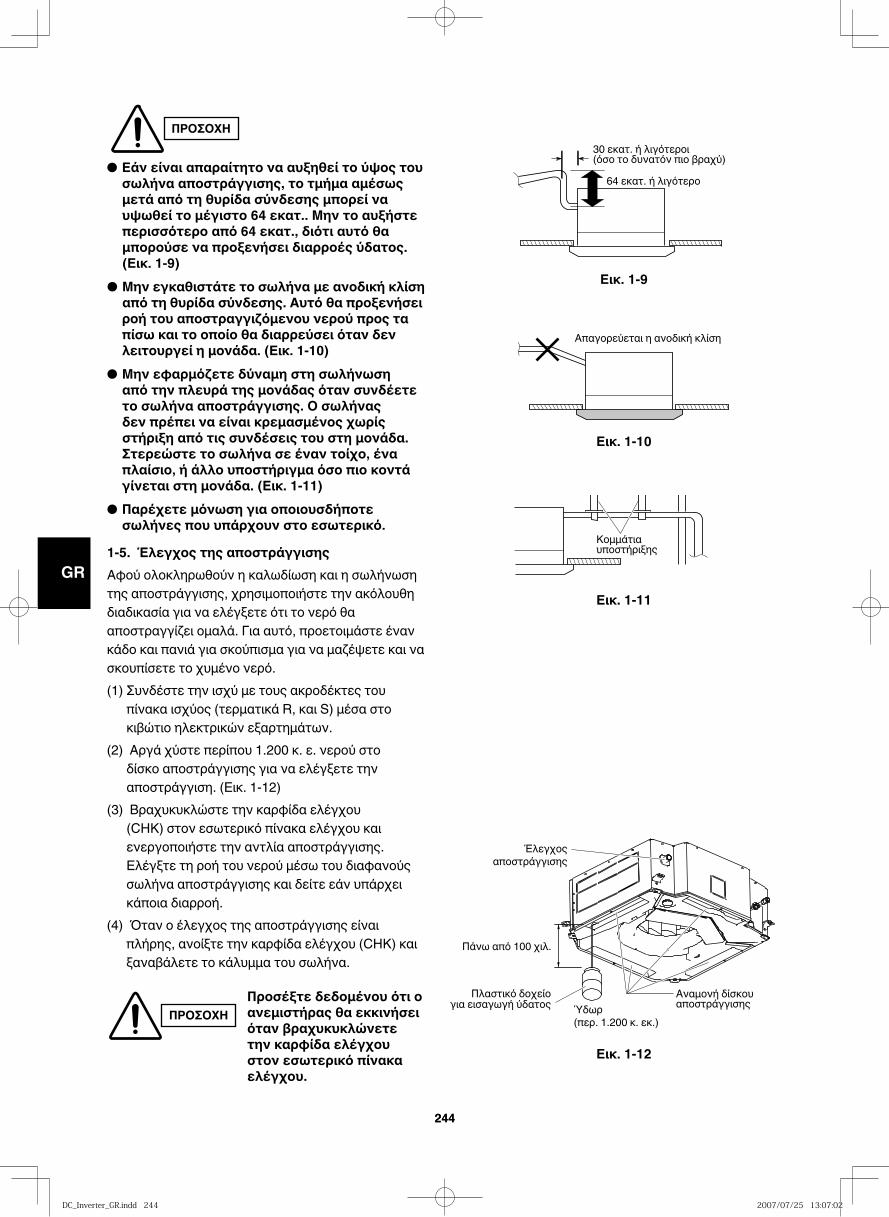
GB
FR
DE
IT
PT
GR
ES
244244
Εικ. 1-9
30 εκατ. ή λιγότεροι (όσο το δυνατόν πιο βραχύ)
64 εκατ. ή λιγότερο
Εικ. 1-10
Απαγορεύεται η ανοδική κλίση
Εικ. 1-11
Εικ. 1-12
Κομμάτιαυποστήριξης
Ύδωρ(περ. 1.200 κ. εκ.)
Αναμονή δίσκου αποστράγγισης
Έλεγχοςαποστράγγισης
Πάνω από 100 χιλ.
Πλαστικό δοχείογια εισαγωγή ύδατος
ΠΡΟΣΟΧΗ
● Εάν είναι απαραίτητο να αυξηθεί το ύψος του σωλήνα αποστράγγισης, το τμήμα αμέσως μετά από τη θυρίδα σύνδεσης μπορεί να υψωθεί το μέγιστο 64 εκατ.. Μην το αυξήστε περισσότερο από 64 εκατ., διότι αυτό θα μπορούσε να προξενήσει διαρροές ύδατος. (Εικ. 1-9)
● Μην εγκαθιστάτε το σωλήνα με ανοδική κλίση από τη θυρίδα σύνδεσης. Αυτό θα προξενήσει ροή του αποστραγγιζόμενου νερού προς τα πίσω και το οποίο θα διαρρεύσει όταν δεν λειτουργεί η μονάδα. (Εικ. 1-10)
● Μην εφαρμόζετε δύναμη στη σωλήνωση από την πλευρά της μονάδας όταν συνδέετε το σωλήνα αποστράγγισης. Ο σωλήνας δεν πρέπει να είναι κρεμασμένος χωρίς στήριξη από τις συνδέσεις του στη μονάδα. Στερεώστε το σωλήνα σε έναν τοίχο, ένα πλαίσιο, ή άλλο υποστήριγμα όσο πιο κοντά γίνεται στη μονάδα. (Εικ. 1-11)
● Παρέχετε μόνωση για οποιουσδήποτε σωλήνες που υπάρχουν στο εσωτερικό.
1-5. Έλεγχος της αποστράγγισηςΑφού ολοκληρωθούν η καλωδίωση και η σωλήνωση της αποστράγγισης, χρησιμοποιήστε την ακόλουθη διαδικασία για να ελέγξετε ότι το νερό θα αποστραγγίζει ομαλά. Για αυτό, προετοιμάστε έναν κάδο και πανιά για σκούπισμα για να μαζέψετε και να σκουπίσετε το χυμένο νερό. (1) Συνδέστε την ισχύ με τους ακροδέκτες του
πίνακα ισχύος (τερματικά R, και S) μέσα στο κιβώτιο ηλεκτρικών εξαρτημάτων.
(2) Αργά χύστε περίπου 1.200 κ. ε. νερού στο δίσκο αποστράγγισης για να ελέγξετε την αποστράγγιση. (Εικ. 1-12)
(3) Βραχυκυκλώστε την καρφίδα ελέγχου (CHK) στον εσωτερικό πίνακα ελέγχου και ενεργοποιήστε την αντλία αποστράγγισης. Ελέγξτε τη ροή του νερού μέσω του διαφανούς σωλήνα αποστράγγισης και δείτε εάν υπάρχει κάποια διαρροή.
(4) Όταν ο έλεγχος της αποστράγγισης είναι πλήρης, ανοίξτε την καρφίδα ελέγχου (CHK) και ξαναβάλετε το κάλυμμα του σωλήνα.
ΠΡΟΣΟΧΗΠροσέξτε δεδομένου ότι ο ανεμιστήρας θα εκκινήσει όταν βραχυκυκλώνετε την καρφίδα ελέγχου στον εσωτερικό πίνακα ελέγχου.
DC_Inverter_GR.indd 244DC_Inverter_GR.indd 244 2007/07/25 13:07:022007/07/25 13:07:02
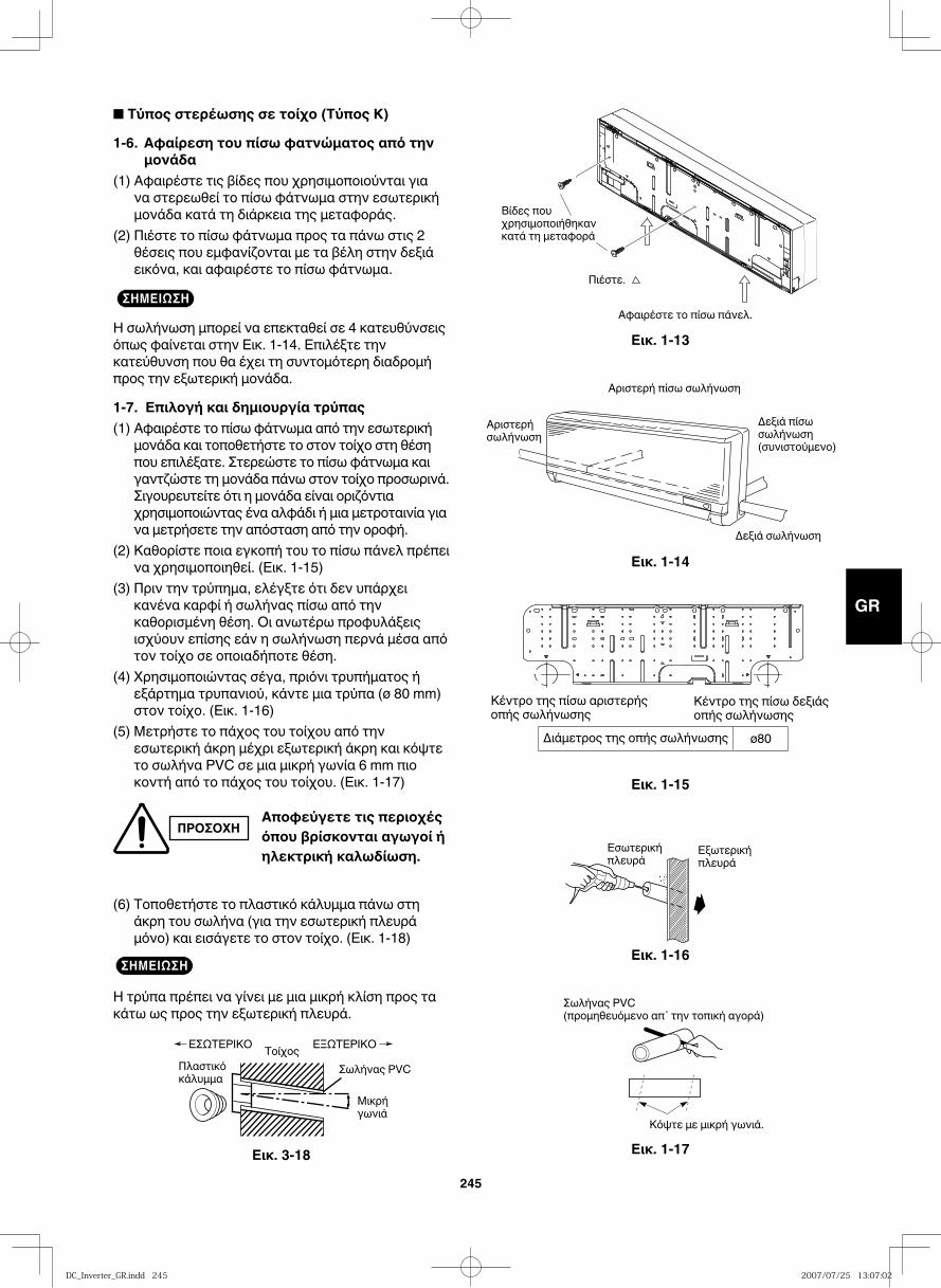
GB
FR
DE
IT
PT
GR
ES
245
■ Τύπος στερέωσης σε τοίχο (Τύπος Κ)
1-6. Αφαίρεση του πίσω φατνώματος από την μονάδα
(1) Αφαιρέστε τις βίδες που χρησιμοποιούνται για να στερεωθεί το πίσω φάτνωμα στην εσωτερική μονάδα κατά τη διάρκεια της μεταφοράς.
(2) Πιέστε το πίσω φάτνωμα προς τα πάνω στις 2 θέσεις που εμφανίζονται με τα βέλη στην δεξιά εικόνα, και αφαιρέστε το πίσω φάτνωμα.
ΣΗΜΕΙΩΣΗ
Η σωλήνωση μπορεί να επεκταθεί σε 4 κατευθύνσεις όπως φαίνεται στην Εικ. 1-14. Επιλέξτε την κατεύθυνση που θα έχει τη συντομότερη διαδρομή προς την εξωτερική μονάδα.
1-7. Επιλογή και δημιουργία τρύπας (1) Αφαιρέστε το πίσω φάτνωμα από την εσωτερική
μονάδα και τοποθετήστε το στον τοίχο στη θέση που επιλέξατε. Στερεώστε το πίσω φάτνωμα και γαντζώστε τη μονάδα πάνω στον τοίχο προσωρινά. Σιγουρευτείτε ότι η μονάδα είναι οριζόντια χρησιμοποιώντας ένα αλφάδι ή μια μετροταινία για να μετρήσετε την απόσταση από την οροφή.
(2) Καθορίστε ποια εγκοπή του το πίσω πάνελ πρέπει να χρησιμοποιηθεί. (Εικ. 1-15)
(3) Πριν την τρύπημα, ελέγξτε ότι δεν υπάρχει κανένα καρφί ή σωλήνας πίσω από την καθορισμένη θέση. Οι ανωτέρω προφυλάξεις ισχύουν επίσης εάν η σωλήνωση περνά μέσα από τον τοίχο σε οποιαδήποτε θέση.
(4) Χρησιμοποιώντας σέγα, πριόνι τρυπήματος ή εξάρτημα τρυπανιού, κάντε μια τρύπα (ø 80 mm) στον τοίχο. (Εικ. 1-16)
(5) Μετρήστε το πάχος του τοίχου από την εσωτερική άκρη μέχρι εξωτερική άκρη και κόψτε το σωλήνα PVC σε μια μικρή γωνία 6 mm πιο κοντή από το πάχος του τοίχου. (Εικ. 1-17)
(6) Τοποθετήστε το πλαστικό κάλυμμα πάνω στη άκρη του σωλήνα (για την εσωτερική πλευρά μόνο) και εισάγετε το στον τοίχο. (Εικ. 1-18)
ΣΗΜΕΙΩΣΗ
Η τρύπα πρέπει να γίνει με μια μικρή κλίση προς τα κάτω ως προς την εξωτερική πλευρά.
Εικ. 1-13
Εικ. 1-14
Εικ. 1-15
Εικ. 1-16
Εικ. 1-17Εικ. 3-18
ΠΡΟΣΟΧΗ Αποφεύγετε τις περιοχές όπου βρίσκονται αγωγοί ή ηλεκτρική καλωδίωση.
Πλαστικόκάλυμμα
ΕΣΩΤΕΡΙΚΟ Τοίχος
Μικρήγωνιά
Σωλήνας PVC
ΕΞΩΤΕΡΙΚΟ
Κόψτε με μικρή γωνιά.
Σωλήνας PVC(προμηθευόμενο απ΄ την τοπική αγορά)
Εσωτερικήπλευρά
Εξωτερικήπλευρά
Κέντρο της πίσω αριστερής οπής σωλήνωσης
Κέντρο της πίσω δεξιάς οπής σωλήνωσης
Διάμετρος της οπής σωλήνωσης ø80
Αριστερήσωλήνωση
Δεξιά πίσωσωλήνωση(συνιστούμενο)
Δεξιά σωλήνωση
Αριστερή πίσω σωλήνωση
Αφαιρέστε το πίσω πάνελ.
Πιέστε.
Βίδες που χρησιμοποιήθηκαν κατά τη μεταφορά
DC_Inverter_GR.indd 245DC_Inverter_GR.indd 245 2007/07/25 13:07:022007/07/25 13:07:02
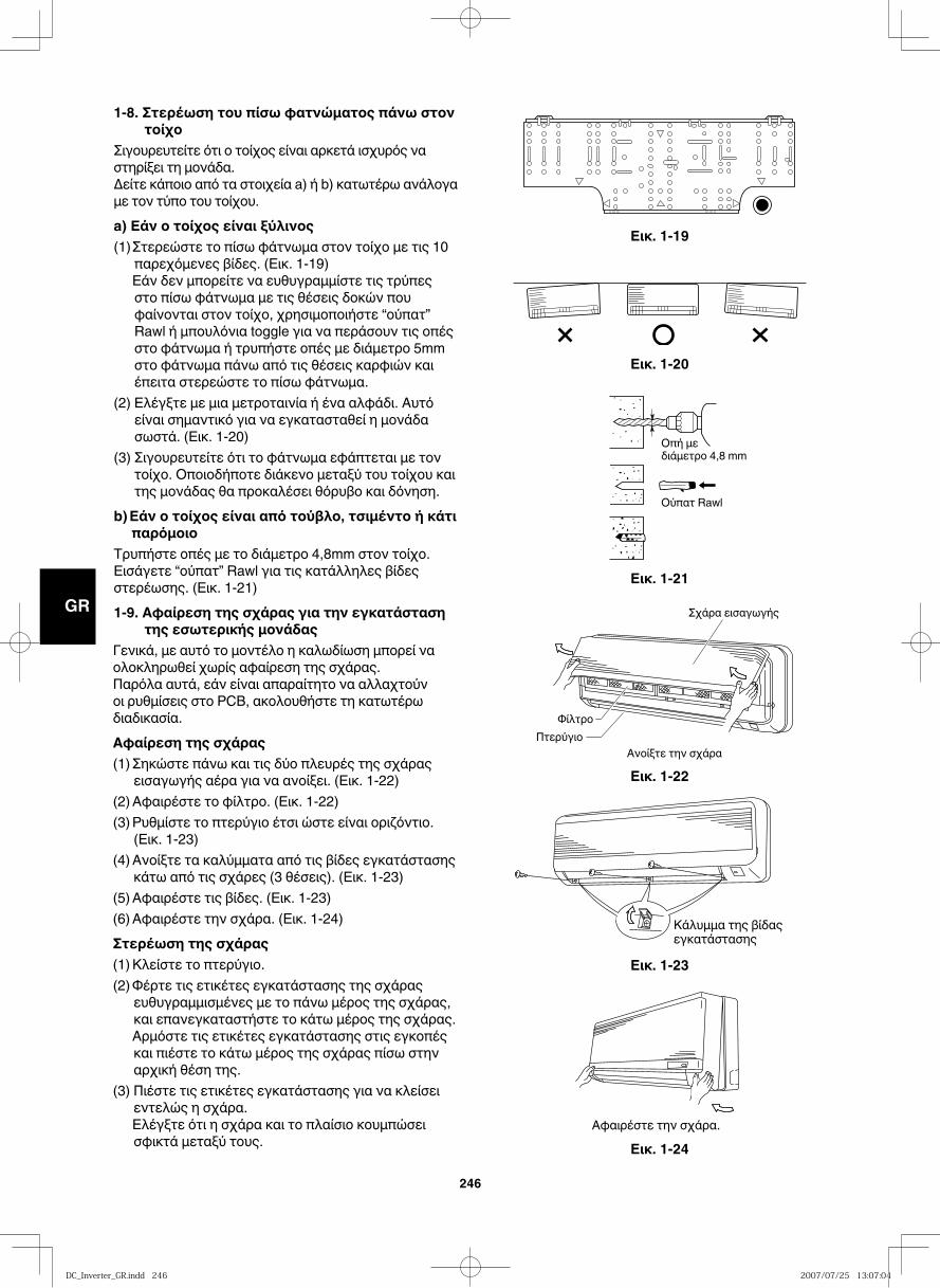
GB
FR
DE
IT
PT
GR
ES
246
Εικ. 1-19
1-8. Στερέωση του πίσω φατνώματος πάνω στον τοίχο
Σιγουρευτείτε ότι ο τοίχος είναι αρκετά ισχυρός να στηρίξει τη μονάδα.Δείτε κάποιο από τα στοιχεία a) ή b) κατωτέρω ανάλογα με τον τύπο του τοίχου.a) Εάν ο τοίχος είναι ξύλινος(1) Στερεώστε το πίσω φάτνωμα στον τοίχο με τις 10
παρεχόμενες βίδες. (Εικ. 1-19) Εάν δεν μπορείτε να ευθυγραμμίστε τις τρύπες
στο πίσω φάτνωμα με τις θέσεις δοκών που φαίνονται στον τοίχο, χρησιμοποιήστε “ούπατ” Rawl ή μπουλόνια toggle για να περάσουν τις οπές στο φάτνωμα ή τρυπήστε οπές με διάμετρο 5mm στο φάτνωμα πάνω από τις θέσεις καρφιών και έπειτα στερεώστε το πίσω φάτνωμα.
(2) Ελέγξτε με μια μετροταινία ή ένα αλφάδι. Αυτό είναι σημαντικό για να εγκατασταθεί η μονάδα σωστά. (Εικ. 1-20)
(3) Σιγουρευτείτε ότι το φάτνωμα εφάπτεται με τον τοίχο. Οποιοδήποτε διάκενο μεταξύ του τοίχου και της μονάδας θα προκαλέσει θόρυβο και δόνηση.
b) Εάν ο τοίχος είναι από τούβλο, τσιμέντο ή κάτι παρόμοιο
Τρυπήστε οπές με το διάμετρο 4,8mm στον τοίχο. Εισάγετε “ούπατ” Rawl για τις κατάλληλες βίδες στερέωσης. (Εικ. 1-21)1-9. Αφαίρεση της σχάρας για την εγκατάσταση
της εσωτερικής μονάδαςΓενικά, με αυτό το μοντέλο η καλωδίωση μπορεί να ολοκληρωθεί χωρίς αφαίρεση της σχάρας.Παρόλα αυτά, εάν είναι απαραίτητο να αλλαχτούν οι ρυθμίσεις στο PCB, ακολουθήστε τη κατωτέρω διαδικασία.Αφαίρεση της σχάρας(1) Σηκώστε πάνω και τις δύο πλευρές της σχάρας
εισαγωγής αέρα για να ανοίξει. (Εικ. 1-22)(2) Αφαιρέστε το φίλτρο. (Εικ. 1-22)(3) Ρυθμίστε το πτερύγιο έτσι ώστε είναι οριζόντιο.
(Εικ. 1-23)(4) Ανοίξτε τα καλύμματα από τις βίδες εγκατάστασης
κάτω από τις σχάρες (3 θέσεις). (Εικ. 1-23)(5) Αφαιρέστε τις βίδες. (Εικ. 1-23)(6) Αφαιρέστε την σχάρα. (Εικ. 1-24)Στερέωση της σχάρας(1) Κλείστε το πτερύγιο.(2) Φέρτε τις ετικέτες εγκατάστασης της σχάρας
ευθυγραμμισμένες με το πάνω μέρος της σχάρας, και επανεγκαταστήστε το κάτω μέρος της σχάρας.
Αρμόστε τις ετικέτες εγκατάστασης στις εγκοπές και πιέστε το κάτω μέρος της σχάρας πίσω στην αρχική θέση της.
(3) Πιέστε τις ετικέτες εγκατάστασης για να κλείσει εντελώς η σχάρα.
Ελέγξτε ότι η σχάρα και το πλαίσιο κουμπώσει σφικτά μεταξύ τους.
Εικ. 1-20
Εικ. 1-21
Εικ. 1-22
Εικ. 1-23
Εικ. 1-24
Οπή μεδιάμετρο 4,8 mm
Ούπατ Rawl
Σχάρα εισαγωγής
ΦίλτροΠτερύγιο
Ανοίξτε την σχάρα
Κάλυμμα της βίδας εγκατάστασης
Αφαιρέστε την σχάρα.
DC_Inverter_GR.indd 246DC_Inverter_GR.indd 246 2007/07/25 13:07:042007/07/25 13:07:04
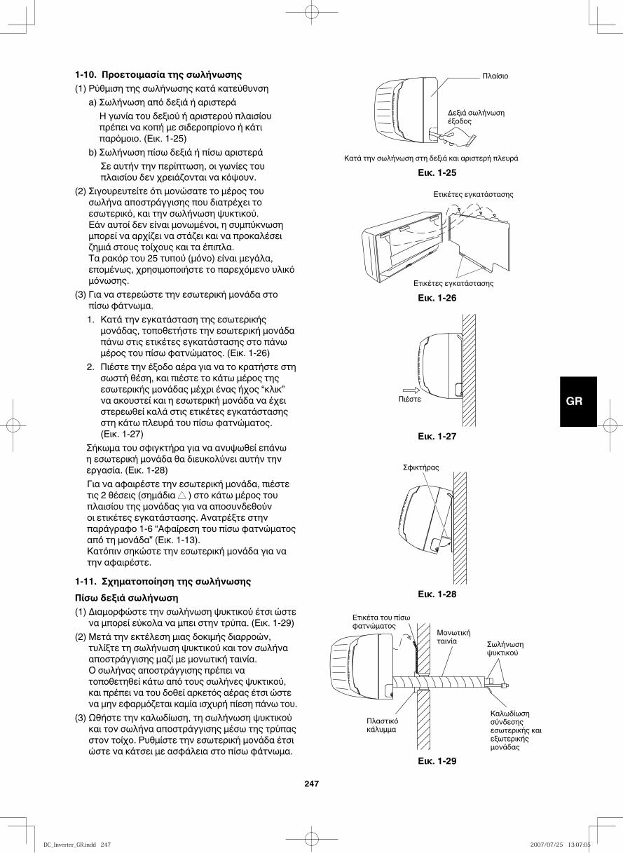
GB
FR
DE
IT
PT
GR
ES
247
1-10. Προετοιμασία της σωλήνωσης(1) Ρύθμιση της σωλήνωσης κατά κατεύθυνση a) Σωλήνωση από δεξιά ή αριστερά
Η γωνία του δεξιού ή αριστερού πλαισίου πρέπει να κοπή με σιδεροπρίονο ή κάτι παρόμοιο. (Εικ. 1-25)
b) Σωλήνωση πίσω δεξιά ή πίσω αριστεράΣε αυτήν την περίπτωση, οι γωνίες του πλαισίου δεν χρειάζονται να κόψουν.
(2) Σιγουρευτείτε ότι μονώσατε το μέρος του σωλήνα αποστράγγισης που διατρέχει το εσωτερικό, και την σωλήνωση ψυκτικού.
Εάν αυτοί δεν είναι μονωμένοι, η συμπύκνωση μπορεί να αρχίζει να στάζει και να προκαλέσει ζημιά στους τοίχους και τα έπιπλα.
Τα ρακόρ του 25 τυπού (μόνο) είναι μεγάλα, επομένως, χρησιμοποιήστε το παρεχόμενο υλικό μόνωσης.
(3) Για να στερεώστε την εσωτερική μονάδα στο πίσω φάτνωμα.1. Κατά την εγκατάσταση της εσωτερικής
μονάδας, τοποθετήστε την εσωτερική μονάδα πάνω στις ετικέτες εγκατάστασης στο πάνω μέρος του πίσω φατνώματος. (Εικ. 1-26)
2. Πιέστε την έξοδο αέρα για να το κρατήστε στη σωστή θέση, και πιέστε το κάτω μέρος της εσωτερικής μονάδας μέχρι ένας ήχος “κλικ” να ακουστεί και η εσωτερική μονάδα να έχει στερεωθεί καλά στις ετικέτες εγκατάστασης στη κάτω πλευρά του πίσω φατνώματος. (Εικ. 1-27)
Σήκωμα του σφιγκτήρα για να ανυψωθεί επάνω η εσωτερική μονάδα θα διευκολύνει αυτήν την εργασία. (Εικ. 1-28)Για να αφαιρέστε την εσωτερική μονάδα, πιέστε τις 2 θέσεις (σημάδια ▲▲ ) στο κάτω μέρος του πλαισίου της μονάδας για να αποσυνδεθούν οι ετικέτες εγκατάστασης. Ανατρέξτε στην παράγραφο 1-6 “Αφαίρεση του πίσω φατνώματος από τη μονάδα” (Εικ. 1-13).Κατόπιν σηκώστε την εσωτερική μονάδα για να την αφαιρέστε.
1-11. Σχηματοποίηση της σωλήνωσηςΠίσω δεξιά σωλήνωση(1) Διαμορφώστε την σωλήνωση ψυκτικού έτσι ώστε
να μπορεί εύκολα να μπει στην τρύπα. (Εικ. 1-29)(2) Μετά την εκτέλεση μιας δοκιμής διαρροών,
τυλίξτε τη σωλήνωση ψυκτικού και τον σωλήνα αποστράγγισης μαζί με μονωτική ταινία.
Ο σωλήνας αποστράγγισης πρέπει να τοποθετηθεί κάτω από τους σωλήνες ψυκτικού, και πρέπει να του δοθεί αρκετός αέρας έτσι ώστε να μην εφαρμόζεται καμία ισχυρή πίεση πάνω του.
(3) Ωθήστε την καλωδίωση, τη σωλήνωση ψυκτικού και τον σωλήνα αποστράγγισης μέσω της τρύπας στον τοίχο. Ρυθμίστε την εσωτερική μονάδα έτσι ώστε να κάτσει με ασφάλεια στο πίσω φάτνωμα.
Εικ. 1-25
Πλαίσιο
Δεξιά σωλήνωσηέξοδος
Κατά την σωλήνωση στη δεξιά και αριστερή πλευρά
Εικ. 1-26
Ετικέτες εγκατάστασης
Ετικέτες εγκατάστασης
Εικ. 1-27
Πιέστε
Εικ. 1-28
Σφικτήρας
Εικ. 1-29
Μονωτικήταινία Σωλήνωση
ψυκτικού
Ετικέτα του πίσωφατνώματος
Πλαστικό κάλυμμα
Καλωδίωση σύνδεσης εσωτερικής και εξωτερικής μονάδας
DC_Inverter_GR.indd 247DC_Inverter_GR.indd 247 2007/07/25 13:07:052007/07/25 13:07:05
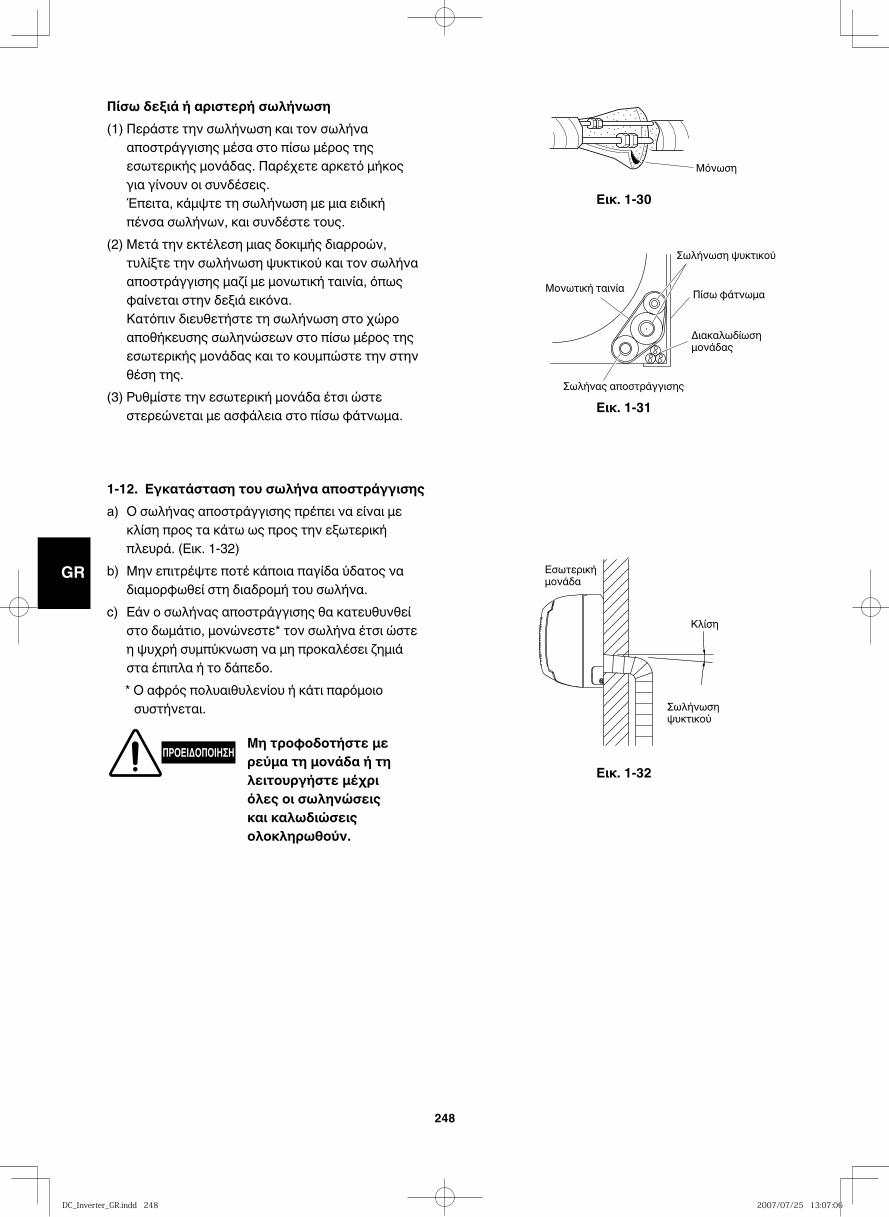
GB
FR
DE
IT
PT
GR
ES
248
Εικ. 1-32
Εικ. 1-30
Μόνωση
Εικ. 1-31
Μονωτική ταινία Πίσω φάτνωμα
Διακαλωδίωσημονάδας
Σωλήνωση ψυκτικού
Σωλήνας αποστράγγισης
Εσωτερικήμονάδα
Κλίση
Σωλήνωσηψυκτικού
1-12. Εγκατάσταση του σωλήνα αποστράγγισηςa) Ο σωλήνας αποστράγγισης πρέπει να είναι με
κλίση προς τα κάτω ως προς την εξωτερική πλευρά. (Εικ. 1-32)
b) Μην επιτρέψτε ποτέ κάποια παγίδα ύδατος να διαμορφωθεί στη διαδρομή του σωλήνα.
c) Εάν ο σωλήνας αποστράγγισης θα κατευθυνθεί στο δωμάτιο, μονώνεστε* τον σωλήνα έτσι ώστε η ψυχρή συμπύκνωση να μη προκαλέσει ζημιά στα έπιπλα ή το δάπεδο.* Ο αφρός πολυαιθυλενίου ή κάτι παρόμοιο συστήνεται.
ΠΡΟΕΙΔΟΠΟΙΗΣΗ Μη τροφοδοτήστε με ρεύμα τη μονάδα ή τη λειτουργήστε μέχρι όλες οι σωληνώσεις και καλωδιώσεις ολοκληρωθούν.
Πίσω δεξιά ή αριστερή σωλήνωση (1) Περάστε την σωλήνωση και τον σωλήνα
αποστράγγισης μέσα στο πίσω μέρος της εσωτερικής μονάδας. Παρέχετε αρκετό μήκος για γίνουν οι συνδέσεις.
Έπειτα, κάμψτε τη σωλήνωση με μια ειδική πένσα σωλήνων, και συνδέστε τους.
(2) Μετά την εκτέλεση μιας δοκιμής διαρροών, τυλίξτε την σωλήνωση ψυκτικού και τον σωλήνα αποστράγγισης μαζί με μονωτική ταινία, όπως φαίνεται στην δεξιά εικόνα.
Κατόπιν διευθετήστε τη σωλήνωση στο χώρο αποθήκευσης σωληνώσεων στο πίσω μέρος της εσωτερικής μονάδας και το κουμπώστε την στην θέση της.
(3) Ρυθμίστε την εσωτερική μονάδα έτσι ώστε στερεώνεται με ασφάλεια στο πίσω φάτνωμα.
DC_Inverter_GR.indd 248DC_Inverter_GR.indd 248 2007/07/25 13:07:062007/07/25 13:07:06
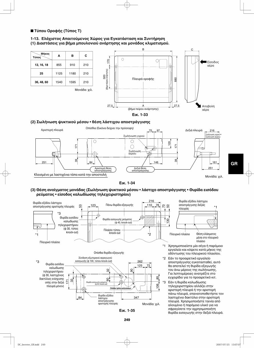
GB
FR
DE
IT
PT
GR
ES
249249
■ Τύπου Οροφής (Τύπος T)
1-13. Ελάχιστος Απαιτούμενος Χώρος για Εγκατάσταση και Συντήρηση(1) Διαστάσεις για βήμα μπουλονιού ανάρτησης και μονάδος κλιματισμού.
12, 16, 18
25
36, 48, 60
855
1125
1540
910
1180
1595
210
210
210
A B C Μήκος
Τύπος
B C
A17
032
0
680
27,5 27,5
Πλευρά οροφής
(βήμα πείρου ανάρτησης)(βή
μα πε
ίρου α
νάρτη
σης)
(2) Σωλήνωση ψυκτικού μέσου • θέση λάστιχου αποστράγγισης
(3) Θέση ανοίγματος μονάδας (Σωλήνωση ψυκτικού μέσου • λάστιχο αποστράγγισης • Θυρίδα εισόδου ρεύματος • είσοδος καλωδίωσης τηλεχειριστηρίου)
251 84 146 161
75 97 216
39 39
171 10
5
171
251
53 70123 110 76216
5013
0
Θυρίδα εξόδου λάστιχου αποστράγγισης αριστερής πλευράς
Θυρίδα εξόδου λάστιχου αποστράγγισης αριστερής πλευράς
Θυρίδα εξόδου λάστιχου αποστράγγισης δεξιάςπλευράς
Πάνω θυρίδα εξαγωγής
Θυρίδα εισόδου καλωδίωσης
τηλεχειριστήριου(φ 30, τύπος
knock-out)
Θυρίδα εισαγωγής ρεύματος(φ 40, knock-out)
Θυρίδα εισαγωγής ρεύματος (φ 40, knock-out)
Πλαίσiο τύπουknock-out
Πλευρικό πλαίσιο
Πλευρικό πλαίσιο Θέση ελάσματος μέσα στο πλευρικό πλαίσιο
84
32
3260
171
347
125 72
8510
6
90
262Θυρίδα εισόδου καλωδίωσης
τηλεχειριστήριου (φ 30, λαστιχένιος
δακτύλιος ενίσχυσης οπής στην δεξιά
πλευρά μόνον)
Σύνδεση εξωτερικού αεραγωγού εισαγωγής (φ 100, τύπου knock-out)
Οπίσθια θυρίδα εξαγωγής
*3
*1
*1
*2
*3
Οπίσθια τρύπα σωληνώσεωνΟπίσθια τρύπα σωληνώσεων
Εικ. 1-33
Εικ. 1-35
Εικ. 1-34
*1 Χρησιμοποιείστε μία σέγα ή παρόμοιο εργαλείο και κόψετε κατά μήκος της οδόντωσης του πλευρικού πλαισίου.
*2 Εάν το προαιρετικό εργαλείο αποστράγγισης εγκατασταθεί, αυτό θα αποτελεί τη θυρίδα εξαγωγής του άνω μέρους της σωλήνωσης, Για λεπτομέρειες ανατρέξτε στο εγχειρίδιο για το προαιρετικό κιτ.
*3 Εάν η θυρίδα καλωδίωσης τηλεχειριστηρίου αλλάζει στην αριστερή πλευρά ή την αριστερή πάνω πλευρά, επανατοποθετήστε τον λαστιχένιο δακτύλιο στην αριστερή πλευρά. Χρησιμοποιήστε ταινία από αλουμίνιο ή παρόμοιο υλικό για να σφραγίσετε την αχρησιμοποιήτη θυρίδα εισαγωγής στην δεξιά πλευρά.
Μονάδα: χιλ.
Μονάδα: χιλ.
Μονάδα: χιλ.
DC_Inverter_GR.indd 249DC_Inverter_GR.indd 249 2007/07/25 13:07:072007/07/25 13:07:07
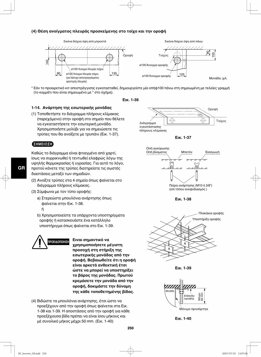
GB
FR
DE
IT
PT
GR
ES
250250
(4) Θέση ανοίγματος πλευράς προσκείμενης στο τοίχο και την οροφή
90
145
135 125
15590
*
Εικ. 1-37
Εικ. 1-36
Εικ. 1-38
1-14. Ανάρτηση της εσωτερικής μονάδας(1) Τοποθετήστε το διάγραμμα πλήρους κλίμακας
(παρεχόμενο) στην οροφή στο σημείο που θέλετε να εγκαταστήσετε την εσωτερική μονάδα. Χρησιμοποιήστε μολύβι για να σημειώσετε τις τρύπες που θα ανοίξετε με τρυπάνι (Εικ. 1-37).
ΣΗΜΕΙΩΣΗ
Καθώς το διάγραμμα είναι φτιαγμένο από χαρτί, ίσως να συρρικνωθεί ή τεντωθεί ελαφρώς λόγω της υψηλής θερμοκρασίας ή υγρασίας. Για αυτό το λόγο, προτού κάνετε της τρύπες διατηρείστε τις σωστές διαστάσεις μεταξύ των σημαδιών.(2) Ανοίξτε τρύπες στα 4 σημεία όπως φαίνεται στο
διάγραμμα πλήρους κλίμακας.(3) Σύμφωνα με τον τύπο οροφής:
a) Στερεώστε μπουλόνια ανάρτησης όπως φαίνεται στην Εικ. 1-38. ή
b) Χρησιμοποιείστε τα υπάρχοντα υποστηρίγματα οροφής ή κατασκευάστε ένα κατάλληλο υποστήριγμα όπως φαίνεται στο Εικ. 1-39.
ΠΡΟΕΙΔΟΠΟΙΗΣΗ Ειναι σημαντικό να χρησιμοποιήσετε μέγιστη προσοχή στη στήριξη της εσωτερικής μονάδας από την οροφή. Βεβαιωθείτε ότι η οροφή είναι αρκετά ανθεκτική έτσι ώστε να μπορεί να υποστηρίξει το βάρος της μονάδας. Πρωτού κρεμάσετε την μονάδα από την οροφή, δοκιμάστε την δύναμη της κάθε τοποθετημένης βίδας.
(4) Βιδώστε τα μπουλόνια ανάρτησης, έτσι ώστε να προεξέχουν από την οροφή όπως φαίνεται στα Εικ. 1-38 και 1-39. Η αποστάσεις από την οροφή για κάθε προεξέχουσα βίδα πρέπει να είναι ίσου μήκους και μέ συνολικό μήκος μέχρι 50 mm. (Εικ. 1-40)
Οπή αγκύρωσηςΟπή βύσματος Μπετόν Εισαγωγή
Πείροι ανάρτησης (Μ10 ή 3/8")(επί τόπου ανεφοδιασμός )
Εικ. 1-39
Εικ. 1-40
Πλακάκια οροφήςΥποστήριξη οροφής
A
A
Μονάδα
* Εάν το προαιρετικό κιτ αποστράγγισης εγκατασταθεί, δημιουργείστε μία οπήφ100 πάνω στη σημειωμένη με τελείες γραμμή (το κομμάτι που είναι σημειωμένο με * στο σχήμα).
Μονάδα: χιλ.
DC_Inverter_GR.indd 250DC_Inverter_GR.indd 250 2007/07/25 13:07:082007/07/25 13:07:08
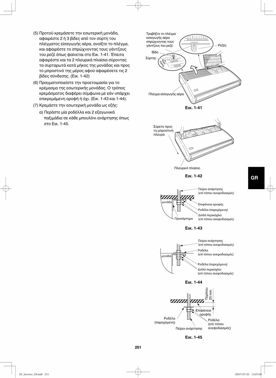
GB
FR
DE
IT
PT
GR
ES
251251
Εικ. 1-41Φοράσύρσης
Ρεζές
Πλέγμα είσαγωγής αέρα
ΒίδαΣύρτης
Τραβήξτε το πλέγμα εισαγωγής αέρα σπρώχνοντας τους γάντζους του ρεζέ
Εικ. 1-42
Πλευρικό πλαίσιο
Σύρετε προς τη μπροστινή πλευρά
Εικ. 1-43
Εικ. 1-44
Εικ. 1-45
Επιφάνεια οροφής
Περίπ
ου
25 m
m
Ροδέλα(παρεχόμενη) Ροδέλα
(επί τόπου ανεφοδιασμός)Πείροι ανάρτησης
(5) Προτού κρεμάσετε την εσωτερική μονάδα, αφαιρέστε 2 ή 3 βίδες από τον σύρτη του πλέγματος είσαγωγής αέρα, ανοίξτε το πλέγμα, και αφαιρέστε το σπρώχνοντας τους γάντζους του ρεζέ όπως φαίνεται στο Εικ. 1-41. Έπειτα αφαιρέστε και τα 2 πλευρικά πλαίσια σύροντας τα συρταρωτά κατά μήκος της μονάδας και προς το μπροστινό της μέρος αφού αφαιρέσετε τις 2 βίδες σύνδεσης. (Εικ. 1-42)
(6) Πραγματοποιείστε την προετοιμασία για το κρέμασμα της εσωτερικής μονάδας. Ο τρόπος κρεμάσματος διαφέρει σύμφωνα με εάν υπάρχει επικρεμάμενη οροφή ή όχι. (Εικ. 1-43 και 1-44).
(7) Κρεμάστε την εσωτερική μονάδα ως εξής: α) Περάστε μία ροδέλλα και 2 εξαγωνικά
παξιμάδια σε κάθε μπουλόνι ανάρτησης όπως στο Εικ. 1-45.
DC_Inverter_GR.indd 251DC_Inverter_GR.indd 251 2007/07/25 13:07:082007/07/25 13:07:08
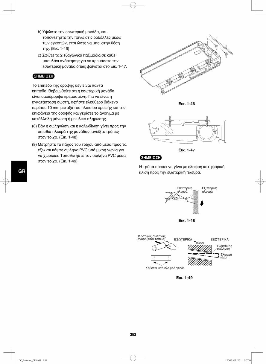
GB
FR
DE
IT
PT
GR
ES
252252
Εικ. 1-46
Εικ. 1-47
Εικ. 1-48
Εικ. 1-49
b) Υψώστε την εσωτερική μονάδα, και τοποθετήστε την πάνω στις ροδέλλες μέσω των εγκοπών, έτσι ώστε να μπει στην θέση της. (Εικ. 1-46)
c) Σφίξτε τα 2 εξαγωνικά παξιμάδια σε κάθε μπουλόνι ανάρτησης για να κρεμάσετε την εσωτερική μονάδα όπως φαίνεται στο Εικ. 1-47.
ΣΗΜΕΙΩΣΗ
Το επίπεδο της οροφής δεν είναι πάντα επίπεδο. Βεβαιωθείτε ότι η εσωτερική μονάδα είναι ομοιόμορφα κρεμασμένη. Για να είναι η εγκατάσταση σωστή, αφήστε ελεύθερο διάκενο περίπου 10 mm μεταξύ του πλαισίου οροφής και της επιφάνεια της οροφής και γεμίστε το άνοιγμα με κατάλληλη μόνωση ή με υλικό πλήρωσης.
(8) Εάν η σωληνώση και η καλωδίωση γίνει προς την οπίσθια πλευρά της μονάδας, ανοίξτε τρύπες στον τοίχο. (Εικ. 1-48)
(9) Μετρήστε το πάχος του τοίχου από μέσα προς τα έξω και κόψτε σωλήνα PVC υπό μικρή γωνία για να χωρέσει. Τοποθετήστε τον σωλήνα PVC μέσα στον τοίχο. (Εικ. 1-49)
ΣΗΜΕΙΩΣΗ
Η τρύπα πρέπει να γίνει με ελαφρή κατηφορική κλίση προς την εξωτερική πλευρά.
DC_Inverter_GR.indd 252DC_Inverter_GR.indd 252 2007/07/25 13:07:092007/07/25 13:07:09
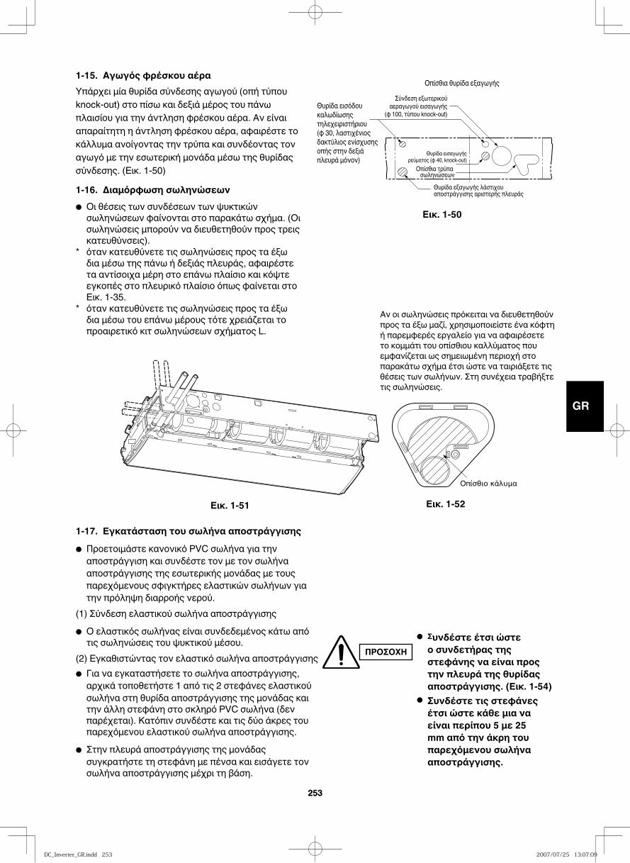
GB
FR
DE
IT
PT
GR
ES
253253
1-15. Αγωγός φρέσκου αέραΥπάρχει μία θυρίδα σύνδεσης αγωγού (οπή τύπου knock-out) στο πίσω και δεξιά μέρος του πάνω πλαισίου για την άντληση φρέσκου αέρα. Αν είναι απαραίτητη η άντληση φρέσκου αέρα, αφαιρέστε το κάλλυμα ανοίγοντας την τρύπα και συνδέοντας τον αγωγό με την εσωτερική μονάδα μέσω της θυρίδας σύνδεσης. (Εικ. 1-50)
1-16. Διαμόρφωση σωληνώσεων● Οι θέσεις των συνδέσεων των ψυκτικών σωληνώσεων φαίνονται στο παρακάτω σχήμα. (Οι σωληνώσεις μπορούν να διευθετηθούν προς τρεις κατευθύνσεις).
* όταν κατευθύνετε τις σωληνώσεις προς τα έξω δια μέσω της πάνω ή δεξιάς πλευράς, αφαιρέστε τα αντίσοιχα μέρη στο επάνω πλαίσιο και κόψτε εγκοπές στο πλευρικό πλαίσιο όπως φαίνεται στο Εικ. 1-35.
* όταν κατευθύνετε τις σωληνώσεις προς τα έξω δια μέσω του επάνω μέρους τότε χρειάζεται το προαιρετικό κιτ σωληνώσεων σχήματος L.
1-17. Εγκατάσταση του σωλήνα αποστράγγισης
● Προετοιμάστε κανoνικό PVC σωλήνα για την αποστράγγιση και συνδέστε τον με τον σωλήνα αποστράγγισης της εσωτερικής μονάδας με τους παρεχόμενους σφιγκτήρες ελαστικών σωλήνων για την πρόληψη διαρροής νερού.
(1) Σύνδεση ελαστικού σωλήνα αποστράγγισης
● Ο ελαστικός σωλήνας είναι συνδεδεμένος κάτω από τις σωληνώσεις του ψυκτικού μέσου.
(2) Εγκαθιστώντας τον ελαστικό σωλήνα αποστράγγισης● Για να εγκαταστήσετε το σωλήνα αποστράγγισης, αρχικά τοποθετήστε 1 από τις 2 στεφάνες ελαστικού σωλήνα στη θυρίδα αποστράγγισης της μονάδας και την άλλη στεφάνη στο σκληρό PVC σωλήνα (δεν παρέχεται). Κατόπιν συνδέστε και τις δύο άκρες του παρεχόμενου ελαστικού σωλήνα αποστράγγισης.
● Στην πλευρά αποστράγγισης της μονάδας συγκρατήστε τη στεφάνη με πένσα και εισάγετε τον σωλήνα αποστράγγισης μέχρι τη βάση.
Θυρίδα εξαγωγής λάστιχου αποστράγγισης αριστερής πλευράς
Θυρίδα εισαγωγής ρεύματος (φ 40, knock-out)
Οπίσθια τρύπα σωληνώσεων
Θυρίδα εισόδου καλωδίωσης τηλεχειριστήριου (φ 30, λαστιχένιος δακτύλιος ενίσχυσης οπής στην δεξιά πλευρά μόνον)
Σύνδεση εξωτερικού αεραγωγού εισαγωγής
(φ 100, τύπου knock-out)
Οπίσθια θυρίδα εξαγωγής
Εικ. 1-50
ΠΡΟΣΟΧΗ● Συνδέστε έτσι ώστε ο συνδετήρας της στεφάνης να είναι προς την πλευρά της θυρίδας αποστράγγισης. (Εικ. 1-54)
● Συνδέστε τις στεφάνες έτσι ώστε κάθε μια να είναι περίπου 5 με 25 mm από την άκρη του παρεχόμενου σωλήνα αποστράγγισης.
Αν οι σωληνώσεις πρόκειται να διευθετηθούν προς τα έξω μαζί, χρησιμοποιείστε ένα κόφτη ή παρεμφερές εργαλείο για να αφαιρέσετε το κομμάτι του οπίσθιου καλλύματος που εμφανίζεται ως σημειωμένη περιοχή στο παρακάτω σχήμα έτσι ώστε να ταιριάξετε τις θέσεις των σωλήνων. Στη συνέχεια τραβήξτε τις σωληνώσεις.
Εικ. 1-51 Εικ. 1-52
DC_Inverter_GR.indd 253DC_Inverter_GR.indd 253 2007/07/25 13:07:092007/07/25 13:07:09
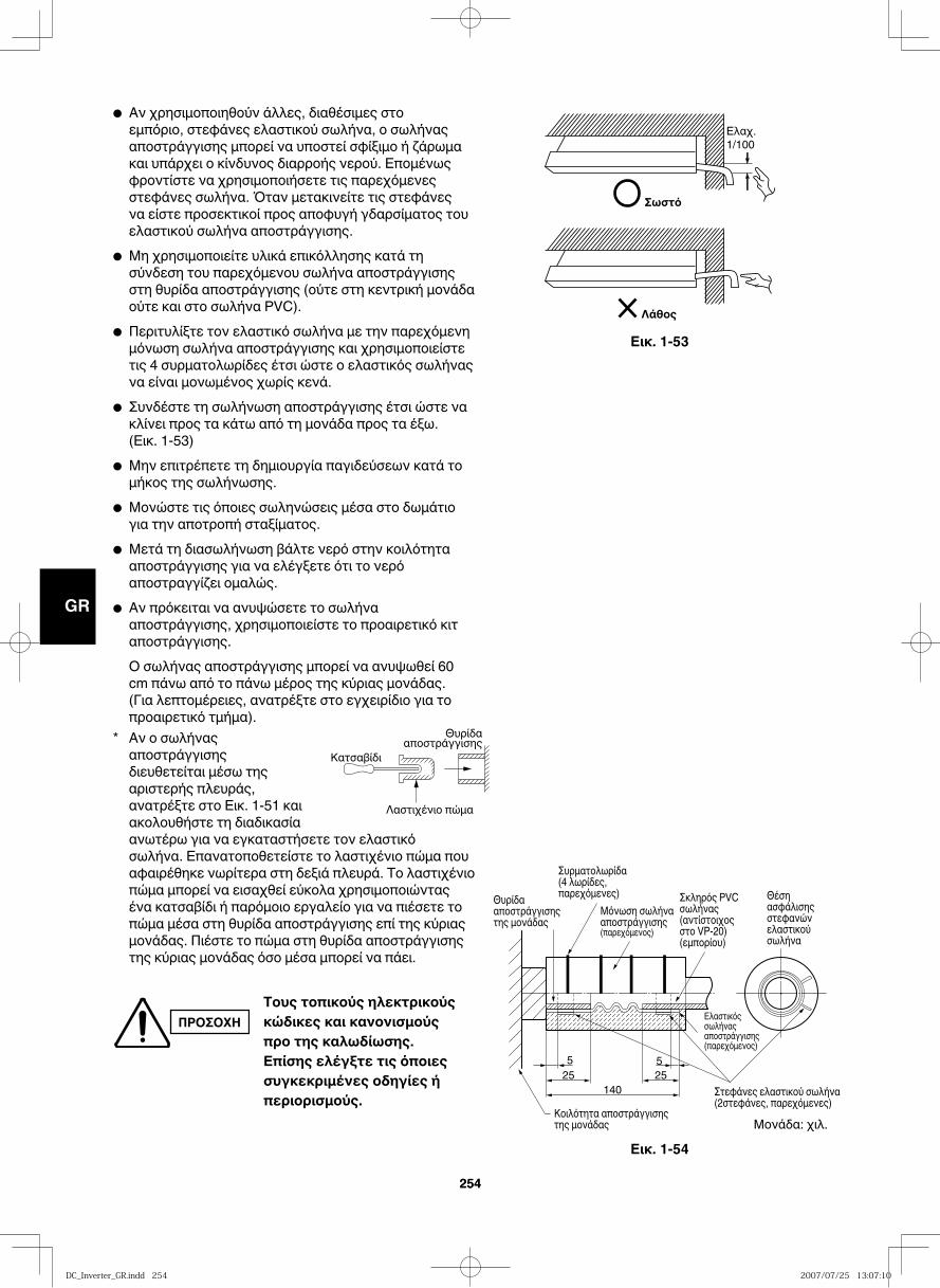
GB
FR
DE
IT
PT
GR
ES
254254
14025 25
55
Θέση ασφάλισης στεφανών ελαστικού σωλήνα
Ελαστικός σωλήνας αποστράγγισης(παρεχόμενος)
Στεφάνες ελαστικού σωλήνα (2στεφάνες, παρεχόμενες)
Κοιλότητα αποστράγγισης της μονάδας
Θυρίδα αποστράγγισης της μονάδας
Μόνωση σωλήνα αποστράγγισης (παρεχόμενος)
Συρματολωρίδα(4 λωρίδες, παρεχόμενες) Σκληρός PVC
σωλήνας(αντίστοιχος στο VP-20)(εμπορίου)
Εικ. 1-54
Σωστό
Ελαχ.1/100
Λάθος
Εικ. 1-53
● Αν χρησιμοποιηθούν άλλες, διαθέσιμες στο εμπόριο, στεφάνες ελαστικού σωλήνα, ο σωλήνας αποστράγγισης μπορεί να υποστεί σφίξιμο ή ζάρωμα και υπάρχει ο κίνδυνος διαρροής νερού. Επομένως φροντίστε να χρησιμοποιήσετε τις παρεχόμενες στεφάνες σωλήνα. Όταν μετακινείτε τις στεφάνες να είστε προσεκτικοί προς αποφυγή γδαρσίματος του ελαστικού σωλήνα αποστράγγισης.
● Μη χρησιμοποιείτε υλικά επικόλλησης κατά τη σύνδεση του παρεχόμενου σωλήνα αποστράγγισης στη θυρίδα αποστράγγισης (ούτε στη κεντρική μονάδα ούτε και στο σωλήνα PVC).
● Περιτυλίξτε τον ελαστικό σωλήνα με την παρεχόμενη μόνωση σωλήνα αποστράγγισης και χρησιμοποιείστε τις 4 συρματολωρίδες έτσι ώστε ο ελαστικός σωλήνας να είναι μονωμένος χωρίς κενά.
● Συνδέστε τη σωλήνωση αποστράγγισης έτσι ώστε να κλίνει προς τα κάτω από τη μονάδα προς τα έξω.(Εικ. 1-53)
● Μην επιτρέπετε τη δημιουργία παγιδεύσεων κατά το μήκος της σωλήνωσης.
● Μονώστε τις όποιες σωληνώσεις μέσα στο δωμάτιο για την αποτροπή σταξίματος.
● Μετά τη διασωλήνωση βάλτε νερό στην κοιλότητα αποστράγγισης για να ελέγξετε ότι το νερό αποστραγγίζει ομαλώς.
● Αν πρόκειται να ανυψώσετε το σωλήνα αποστράγγισης, χρησιμοποιείστε το προαιρετικό κιτ αποστράγγισης.
Ο σωλήνας αποστράγγισης μπορεί να ανυψωθεί 60 cm πάνω από το πάνω μέρος της κύριας μονάδας. (Για λεπτομέρειες, ανατρέξτε στο εγχειρίδιο για το προαιρετικό τμήμα).
* Αν ο σωλήνας αποστράγγισης διευθετείται μέσω της αριστερής πλευράς, ανατρέξτε στο Εικ. 1-51 και ακολουθήστε τη διαδικασία ανωτέρω για να εγκαταστήσετε τον ελαστικό σωλήνα. Επανατοποθετείστε το λαστιχένιο πώμα που αφαιρέθηκε νωρίτερα στη δεξιά πλευρά. Το λαστιχένιο πώμα μπορεί να εισαχθεί εύκολα χρησιμοποιώντας ένα κατσαβίδι ή παρόμοιο εργαλείο για να πιέσετε το πώμα μέσα στη θυρίδα αποστράγγισης επί της κύριας μονάδας. Πιέστε το πώμα στη θυρίδα αποστράγγισης της κύριας μονάδας όσο μέσα μπορεί να πάει.
Κατσαβίδι
Λαστιχένιο πώμα
Θυρίδααποστράγγισης
ΠΡΟΣΟΧΗΤους τοπικούς ηλεκτρικούς κώδικες και κανονισμούς προ της καλωδίωσης. Επίσης ελέγξτε τις όποιες συγκεκριμένες οδηγίες ή περιορισμούς.
Μονάδα: χιλ.
DC_Inverter_GR.indd 254DC_Inverter_GR.indd 254 2007/07/25 13:07:102007/07/25 13:07:10
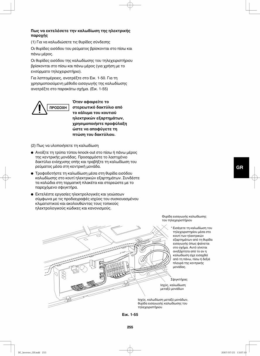
GB
FR
DE
IT
PT
GR
ES
255255
* Εισάγετε τη καλωδίωση του τηλεχειριστηρίου μέσα στο κουτί των ηλεκτρικών εξαρτημάτων από τη θυρίδα εισαγωγής όπως φαίνεται στο σχήμα. Αυτό γίνεται ανεξάρτητα από το αν η καλωδίωση είχε εισαχθεί από τη πάνω, πίσω ή δεξιά πλευρά της κεντρικής μονάδας.
Θυρίδα εισαγωγής καλωδίωσης του τηλεχειριστήριου
Ισχύς, καλωδίωση μεταξύ μονάδων
Ισχύς, καλωδίωση μεταξύ μονάδων, θυρίδα εισαγωγής καλωδίωσης του τηλεχειριστήριου
Σφιγκτήρας
Πως να εκτελέσετε την καλωδίωση της ηλεκτρικής παροχής (1) Για να καλωδιώσετε τις θυρίδες σύνδεσηςΟι θυρίδες εισόδου του ρεύματος βρίσκονται στο πίσω και πάνω μέρος. Οι θυρίδες εισόδου της καλωδίωσης του τηλεχειριστήριου βρίσκονται στο πίσω και πάνω μέρος (για χρήση με το ενσύρματο τηλεχειριστήριο).Για λεπτομέρειες, ανατρέξτε στο Εικ. 1-50. Για τη χρησιμοποιούμενη μέθοδο εισαγωγής της καλωδίωσης ανατρέξτε στο παρακάτω σχήμα. (Εικ. 1-55)
(2) Πως να υλοποιήσετε τη καλωδίωση● Ανοίξτε τη τρύπα τύπου knock-out στο πίσω ή πάνω μέρος της κεντρικής μονάδας. Προσαρμόστε το λαστιχένιο δακτύλιο ενίσχυσης οπής και τραβήξτε τη καλωδίωση του ρεύματος μέσα στη κεντρική μονάδα.
● Τροφοδοτήστε τη καλωδίωση μέσα στη θυρίδα εισόδου καλωδίωσης στο κουτί ηλεκτρικών εξαρτημάτων. Συνδέστε τα καλώδια στη τερματική πλακέτα και στερεώστε με το παρεχόμενο σφιγκτήρα.
● Εκτελέστε εργασίες ηλεκτρολογικές και γειώσεων σύμφωνα με τις προδιαγραφές ισχύος του συσκευασμένου κλιματιστικού και ακολουθώντας τους τοπικούς ηλεκτρολογικούς κώδικες και κανονισμούς.
ΠΡΟΣΟΧΗΌταν αφαιρείτε το στερεωτικό δακτύλιο από το κάλυμα του κουτιού ηλεκτρικών εξαρτημάτων, χρησιμοποιήστε προφύλαξη ώστε να αποφύγετε τη πτώση του δακτύλιου.
Εικ. 1-55
DC_Inverter_GR.indd 255DC_Inverter_GR.indd 255 2007/07/25 13:07:102007/07/25 13:07:10
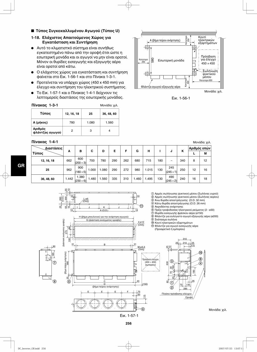
GB
FR
DE
IT
PT
GR
ES
256
Εικ. 1-56-1
Εικ. 1-57-1
Εσωτερική μονάδαΠρόσβασηγια έλεγχο450 × 450
Φλάντζα αγωγού εξαγωγής αέρα
Κατώτερο250
Κατώτερο 650
Κατώ
τερο
400
580
A (βήμα πείρου ανάρτησης)
Σωλήνωση ψυκτικού μέσου
Κατώ
τερο
250 Κουτί
ηλεκτρικών εξαρτημάτων
■ Tύπος Συγκεκαλλυμένου Αγωγού (Τύπος U)1-18. Ελάχιστος Aπαιτούμενος Χώρος για
Εγκατάσταση και Συντήρηση● Αυτό το κλιματιστκό σύστημα είναι συνήθως
εγκατεστημένο πάνω από την οροφή έτσι ώστε η εσωτερική μονάδα και οι αγωγοί να μην είναι ορατοί. Μόνον οι θυρίδες εισαγωγής και εξαγωγής αέρα είναι ορατοί από κάτω.
● Ο ελάχιστος χώρος για εγκατάσταση και συντήρηση φαίνεται στο Εικ. 1-56-1 και στο Πίνακα 1-3-1.
● Προτείνεται να υπάρχει χώρος (450 x 450 mm) για έλεγχο και συντήρηση του ηλεκτρικού συστήματος.
● Το Εικ. 1-57-1 και ο Πίνακας 1-4-1 δείχνουν τις λεπτομερείς διαστάσεις της εσωτερικής μονάδας.
Πίνακας 1-3-1
Πίνακας 1-4-1
Τύπος
A (μήκος)Αριθμόςφλάντζας αγωγού
36, 48, 60
1.560
4
25
1.080
3
12, 16, 18
780
2
ΔιαστάσειςΤύπος
12, 16, 18
25
36, 48, 60
E F G I J K
662 600 700 780 290 262 680 715 180 – 340 8 12(200 × 3)
962 900 1.000 1.080 290 272 980 1.015 130 245 250 12 16(180 × 5) (245 × 1)
1.442 1.380 1.480 1.560 335 310 1.460 1.495 130 490 240 16 18(230 × 6) (245 × 2)
Αριθμός οπώνL M
C DBA H
Άνω θυρίδα αποστράγγισης (O.D. 32 mm)Κάτω θυρίδα αποστράγγισης (O.D. 26 mm)Ακροδέκτης ανάρτησηςΠρίζα τροφοδοσίας ηλεκτρικού ρεύματος (2 - ø30)Θυρίδα εισαγωγής φρέσκου αέρα (ø150)Φλάντζα για ευλύγιστο αγωγό εξαγωγής αέρα (ø200)Σκέπασμα σωλήναΚουτί ηλεκτρικών εξαρτημάτωνΦλάντζα για αγωγό εισαγωγής αέρα(Προαιρετικό ή εμπορίου)
9
10
9
10
11
11
(βήμα πείρου ανάρτησης)
(βήμα
πείρο
υ ανά
ρτησ
ης)
M-ø3,3(Οπή)
4-ø12(Οπή)
(Οπή)
A (O.D.)
L-ø6
I
10 10
105555
200
10 IJJ K
B
CD (150)
40
E E E F 7565
285
70 130
25 210
310
25175
35
903131
H (βήμα μπουλονιού για την ανάρτηση αγωγού)G (Διάσταση ανοίγματος οροφής)
25
100
185
580
25
115
190
85
2570
30 160
630
25 10
8827
5(Δι
άστα
ση αν
οίγμα
τος ορ
οφής
)26
0(O
.D.)
1919
Πρόσβαση ελέγχου(450 × 450)(εμπορίου)
Πλαίσιο πρόσβασης ελέγχουΟροφή
Αρμός σωλήνωσης ψυκτικού μέσου (Σωλήνας αερίου)Αρμός σωλήνωσης ψυκτικού μέσου (Σωλήνας υγρού)
Μονάδα: χιλ.
Μονάδα: χιλ.
Μονάδα: χιλ.
Μονάδα: χιλ.
DC_Inverter_GR.indd 256DC_Inverter_GR.indd 256 2007/07/25 13:07:112007/07/25 13:07:11
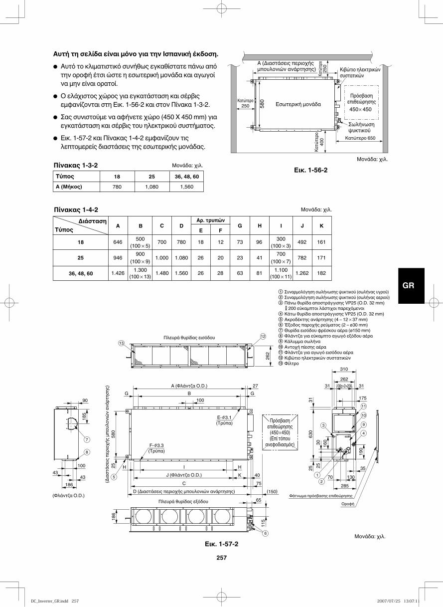
GB
FR
DE
IT
PT
GR
ES
257
Εικ. 1-56-2
Κατώτερο250 58
0
Κατώτερο
400
A (Διαστάσεις περιοχήςμπουλονιών ανάρτησης)
Εσωτερική μονάδα
Κατώτερο 650
Κιβώτιο ηλεκτρικώνσυστατικών
Πρόσβασηεπιθεώρησης450 450
Σωλήνωσηψυκτικού
Κατώτερ
ο25
0
Αυτή τη σελίδα είναι μόνο για την Ισπανική έκδοση.
● Αυτό το κλιματιστικό συνήθως εγκαθίστατε πάνω από την οροφή έτσι ώστε η εσωτερική μονάδα και αγωγοί να μην είναι ορατοί.
● Ο ελάχιστος χώρος για εγκατάσταση και σέρβις εμφανίζονται στη Εικ. 1-56-2 και στον Πίνακα 1-3-2.
● Σας συνιστούμε να αφήνετε χώρο (450 X 450 mm) για εγκατάσταση και σέρβις του ηλεκτρικού συστήματος.
● Εικ. 1-57-2 και Πίνακας 1-4-2 εμφανίζουν τις λεπτομερείς διαστάσεις της εσωτερικής μονάδας.
ΤύποςA (Μήκος)
36, 48, 601,560
251,080
18780
ΔιάστασηΤύπος
18
25
36, 48, 60
E FG H I J K
646 500 700 780 18 12 73 96 492(100 × 5)
946 900 1.000 1.080 26 20 23 41 782(100 × 9)1.426 1.300 1.480 1.560 26 28 63 81 1.262
161
171
182(100 × 13)
300(100 × 3)
700(100 × 7)
1.100(100 × 11)
C DBAΑρ. τρυπών
262
100
580
25 H HI
(Διασ
τάσε
ις πε
ριοχή
ς μπο
υλον
ιών α
νάρτ
ησης
) A (Φλάντζα O.D.)
Πλευρά θυρίδας εισόδου
(Φλάντζα O.D.)Πλευρά θυρίδας εξόδου
J (Φλάντζα O.D.)
27B GG
K 40C
D (Διαστάσεις περιοχής μπουλονιών ανάρτησης)75
(150)
11518
6
65
90
100
4343
185
186
310262
31100p×2=20031
3570 130
175
630
3125
190
285
160
2530
Πρόσβασηεπιθεώρησης
(450 450)(Επί τόπου
ανεφοδιασμός)
E- 3.1(Τρύπα)
F- 3.3(Τρύπα)
Φάτνωμα πρόσβασης επιθεώρησηςΟροφή
12
349
10
11
6
5
7
8
1213
Μονάδα: χιλ.
Μονάδα: χιλ.
Μονάδα: χιλ.
Μονάδα: χιλ.
Συναρμολόγηση σωλήνωσης ψυκτικού (σωλήνας υγρού)Συναρμολόγηση σωλήνωσης ψυκτικού (σωλήνας αεριού)Πάνω θυρίδα αποστράγγισης VP25 (O.D. 32 mm) 200 εύκαμπτοι λάστιχοι παρεχόμενοι Κάτω θυρίδα αποστράγγισης VP25 (O.D. 32 mm)Ακροδέκτης ανάρτησης (4 – 12 37 mm)Έξοδος παροχής ρεύματος (2 – ø30 mm)Θυρίδα εισόδου φρέσκου αέρα (ø150 mm)Φλάντζα για εύκαμπτο αγωγό εξόδου αέρα Κάλυμμα σωλήνα
Φλάντζα για αγωγό εισόδου αέραΚιβώτιο ηλεκτρικών συστατικών
11 Αντοχή πίεσης αέρα10
12
Φίλτρο13
Εικ. 1-57-2
Πίνακας 1-4-2
Πίνακας 1-3-2
DC_Inverter_GR.indd 257DC_Inverter_GR.indd 257 2007/07/25 13:07:112007/07/25 13:07:11
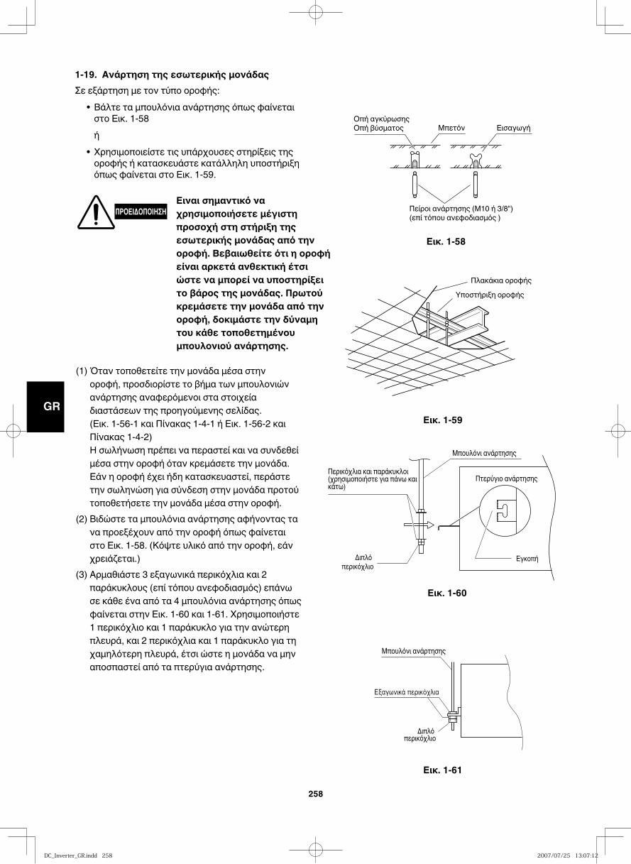
GB
FR
DE
IT
PT
GR
ES
258
Εικ. 1-58
1-19. Ανάρτηση της εσωτερικής μονάδαςΣε εξάρτηση με τον τύπο οροφής:
• Βάλτε τα μπουλόνια ανάρτησης όπως φαίνεται στο Εικ. 1-58
ή• Χρησιμοποιείστε τις υπάρχουσες στηρίξεις της οροφής ή κατασκευάστε κατάλληλη υποστήριξη όπως φαίνεται στο Εικ. 1-59.
Οπή αγκύρωσηςΟπή βύσματος Μπετόν Εισαγωγή
Πείροι ανάρτησης (Μ10 ή 3/8")(επί τόπου ανεφοδιασμός )
Εικ. 1-59
Εικ. 1-60
Εικ. 1-61
Πλακάκια οροφήςΥποστήριξη οροφής
Μπουλόνι ανάρτησης
Πτερύγιο ανάρτησης
Εγκοπή
Περικόχλια και παράκυκλοι (χρησιμοποιήστε για πάνω και κάτω)
Διπλό περικόχλιο
Μπουλόνι ανάρτησης
Διπλό περικόχλιο
ΠΡΟΕΙΔΟΠΟΙΗΣΗΕιναι σημαντικό να χρησιμοποιήσετε μέγιστη προσοχή στη στήριξη της εσωτερικής μονάδας από την οροφή. Βεβαιωθείτε ότι η οροφή είναι αρκετά ανθεκτική έτσι ώστε να μπορεί να υποστηρίξει το βάρος της μονάδας. Πρωτού κρεμάσετε την μονάδα από την οροφή, δοκιμάστε την δύναμη του κάθε τοποθετημένου μπουλονιού ανάρτησης.
(1) Όταν τοποθετείτε την μονάδα μέσα στην οροφή, προσδιορίστε το βήμα των μπουλονιών ανάρτησης αναφερόμενοι στα στοιχεία διαστάσεων της προηγούμενης σελίδας. (Εικ. 1-56-1 και Πίνακας 1-4-1 ή Εικ. 1-56-2 και Πίνακας 1-4-2)
Η σωλήνωση πρέπει να περαστεί και να συνδεθεί μέσα στην οροφή όταν κρεμάσετε την μονάδα. Εάν η οροφή έχει ήδη κατασκευαστεί, περάστε την σωληνώση για σύνδεση στην μονάδα προτού τοποθετήσετε την μονάδα μέσα στην οροφή.
(2) Βιδώστε τα μπουλόνια ανάρτησης αφήνοντας τα να προεξέχουν από την οροφή όπως φαίνεται στο Εικ. 1-58. (Κόψτε υλικό από την οροφή, εάν χρειάζεται.)
(3) Αρμαθιάστε 3 εξαγωνικά περικόχλια και 2 παράκυκλους (επί τόπου ανεφοδιασμός) επάνω σε κάθε ένα από τα 4 μπουλόνια ανάρτησης όπως φαίνεται στην Εικ. 1-60 και 1-61. Χρησιμοποιήστε 1 περικόχλιο και 1 παράκυκλο για την ανώτερη πλευρά, και 2 περικόχλια και 1 παράκυκλο για τη χαμηλότερη πλευρά, έτσι ώστε η μονάδα να μην αποσπαστεί από τα πτερύγια ανάρτησης.
DC_Inverter_GR.indd 258DC_Inverter_GR.indd 258 2007/07/25 13:07:122007/07/25 13:07:12
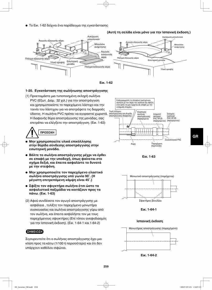
GB
FR
DE
IT
PT
GR
ES
259
● Το Εικ. 1-62 δείχνει ένα παράδειγμα της εγκατάστασης
Εικ. 1-62
Εικ. 1-63
Εικ. 1-64-1
Μονωτικό αποστράγγισης (παρέχεται)
Σφικτήρες βινυλίου
1-20. Εγκατάσταση της σωλήνωσης αποστράγγισης(1) Προετοιμάστε μια τυποποιημένη σκληρή σωλήνα
PVC (Εξωτ. Διαμ. 32 χιλ.) για την αποστράγγιση και χρησιμοποιείστε το παρεχόμενο λάστιχο και την ταινία του λάστιχου για να αποτρέψετε τις διαρροές ύδατος. Η σωλήνα PVC πρέπει να αγοραστεί χωριστά. Η διαφανής θύρα αποστράγγισης της μονάδας, σας επιτρέπει να ελέγξετε την αποστράγγιση. (Εικ. 1-63)
ΠΡΟΣΟΧΗ
● Μην χρησιμοποιείτε υλικά επικόλλησης στην θύρίδα σύνδεσης αποστράγγισης στην εσωτερική μονάδα.
● Βάλτε το σωλήνα αποστράγγισης μέχρι να έρθει σε επαφή με την υποδοχή, όπως φαίνεται στο σχήμα δεξιά, και έπειτα ασφαλίστε το δυνατά με την στεφάνη.
● Μην χρησιμοποιείτε τον παρεχόμενο ελαστικό σωλήνα αποστράγγισης υπό γωνία 90˚. (Η μέγιστη επιτρεπόμενη κάμψη είναι 45˚.)
● Σφίξτε τον σφιγκτήρα σωλήνα έτσι ώστε τα ασφαλιστικά παξιμάδια να κοιτάζουν προς τα πάνω. (Εικ. 1-63)
(2) Αφού συνδέσετε τον αγωγό αποστράγγισης με ασφάλεια , τυλίξτε τον παρεχόμενο μονωτήρα συσκευασίας και σωλήνα αποστράγγισης γύρω από τον σωλήνα, και έπειτα ασφαλήστε τον με τους παρεχόμενους σφιγκτήρες (Επί τόπου ανεφοδιασμός για την Ισπανική έκδοση). (Εικ. 1-64-1 και 1-64-2)
ΣΗΜΕΙΩΣΗ
Σιγουρευτείτε ότι ο σωλήνας αποστράγγισης έχει μια κλίση προς τα κάτω (1/100 ή περισσότερο) και ότι δεν υπάρχουν καθόλου σιφώνια.
Αγωγός εξαγωγής αέρα
Πλέγμα εξαγωγής αέραΥλικό οροφής Εσωτερική
μονάδα
Αγκύρωσημπουλονιού
Μπουλόνιανάρτησης
Αγωγόςεισαγωγήςαέρα
Πλέγμα εισαγωγής αέρα
Αγωγός εξαγωγής αέρα
Πλέγμα εξαγωγής αέρα
Υλικό οροφής
Εσωτερική μονάδα
Αγκύρωση μπουλονιού
Μπουλόνιανάρτησης
(Αυτή τη σελίδα είναι μόνο για την Ισπανική έκδοση.)
Εικ. 1-64-2
Μονωτήρας αποστράγγισης (παρεχόμενο)
Ισπανική έκδοση
DC_Inverter_GR.indd 259DC_Inverter_GR.indd 259 2007/07/25 13:07:132007/07/25 13:07:13
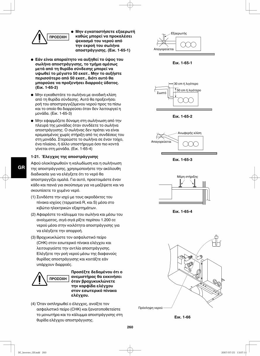
GB
FR
DE
IT
PT
GR
ES
260
Εικ. 1-65-1
Εικ. 1-65-2
Εικ. 1-65-3
Εικ. 1-65-4
Εικ. 1-66
Εξαερωτής
Απαγορεύεται
Σωστό
30 cm ή λιγότερo50 cm ή λιγότερo
Απαγορεύεται
Ανωφερής κλίση
Μέρη στήριξης
Πρόσληψη νερού
● Εάν είναι απαραίτητο να αυξηθεί το ύψος του σωλήνα αποστράγγισης, το τμήμα αμέσως μετά από τη θυρίδα σύνδεσης μπορεί να υψωθεί το μέγιστο 50 εκατ.. Μην το αυξήστε περισσότερο από 50 εκατ., διότι αυτό θα μπορούσε να προξενήσει διαρροές ύδατος. (Εικ. 1-65-2)
● Μην εγκαθιστάτε το σωλήνα με ανοδική κλίση από τη θυρίδα σύνδεσης. Αυτό θα προξενήσει ροή του αποστραγγιζόμενου νερού προς τα πίσω και το οποίο θα διαρρεύσει όταν δεν λειτουργεί η μονάδα. (Εικ. 1-65-3)
● Μην εφαρμόζετε δύναμη στη σωλήνωση από την πλευρά της μονάδας όταν συνδέετε το σωλήνα αποστράγγισης. Ο σωλήνας δεν πρέπει να είναι κρεμασμένος χωρίς στήριξη από τις συνδέσεις του στη μονάδα. Στερεώστε το σωλήνα σε έναν τοίχο, ένα πλαίσιο, ή άλλο υποστήριγμα όσο πιο κοντά γίνεται στη μονάδα. (Εικ. 1-65-4)
1-21. Έλεγχος της αποστράγγισηςΑφού ολοκληρωθούν η καλωδίωση και η σωλήνωση της αποστράγγισης, χρησιμοποιήστε την ακόλουθη διαδικασία για να ελέγξετε ότι το νερό θα αποστραγγίζει ομαλά. Για αυτό, προετοιμάστε έναν κάδο και πανιά για σκούπισμα για να μαζέψετε και να σκουπίσετε το χυμένο νερό.(1) Συνδέστε την ισχύ με τους ακροδέκτες του
πίνακα ισχύος (τερματικά R, και S) μέσα στο κιβώτιο ηλεκτρικών εξαρτημάτων.
(2) Αφαιρέστε το κάλυμμα του σωλήνα και μέσω του ανοίγματος, σιγά σιγά ρίξτε περίπου 1.200 cc νερού μέσα στην κοιλότητα αποστράγγισης για να ελέγξετε την απορροή.
(3) Βραχυκυκλώστε τον ασφαλιστικό πείρο (CHK) στον εσωτερικό πίνακα ελέγχου και λειτουργείστε την αντλία αποστράγγισης. Ελέγξετε την ροή νερού μέσω της διαφανούς θυρίδας αποστράγγισης και κοιτάξτε εάν υπάρχουν διαρροές.
(4) Όταν εκπληρωθεί ο έλεγχος, ανοίξτε τον ασφαλιστικό πείρο (CHK) και ξανατοποθετείστε το μονωτήρα και το κάλυμμα αποστράγγισης στη θυρίδα ελέγχου αποστράγγισης.
ΠΡΟΣΟΧΗ● Mην εγκαταστήσετε εξαερωτή καθώς μπορεί να προκαλέσει ψεκασμό του νερού από την εκροή του σωλήνα αποστράγγισης. (Εικ. 1-65-1)
ΠΡΟΣΟΧΗΠροσέξτε δεδομένου ότι ο ανεμιστήρας θα εκκινήσει όταν βραχυκυκλώνετε την καρφίδα ελέγχου στον εσωτερικό πίνακα ελέγχου.
DC_Inverter_GR.indd 260DC_Inverter_GR.indd 260 2007/07/25 13:07:142007/07/25 13:07:14
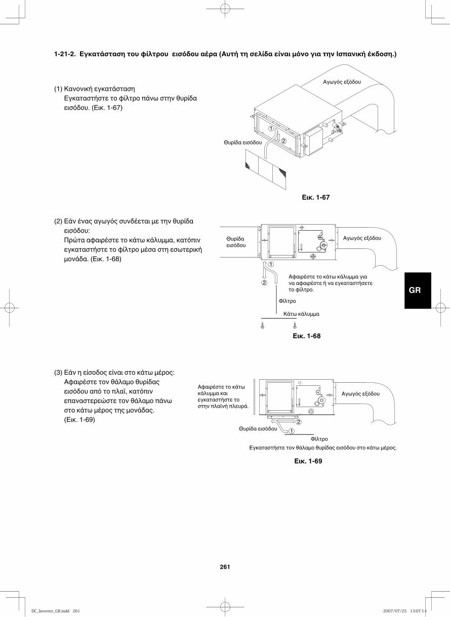
GB
FR
DE
IT
PT
GR
ES
261
(1) Κανονική εγκατάσταση Εγκαταστήστε το φίλτρο πάνω στην θυρίδα εισόδου. (Εικ. 1-67)
(2) Εάν ένας αγωγός συνδέεται με την θυρίδα εισόδου:Πρώτα αφαιρέστε το κάτω κάλυμμα, κατόπιν εγκαταστήστε το φίλτρο μέσα στη εσωτερική μονάδα. (Εικ. 1-68)
(3) Εάν η είσοδος είναι στο κάτω μέρος:Αφαιρέστε τον θάλαμο θυρίδας εισόδου από το πλαϊ, κατόπιν επαναστερεώστε τον θάλαμο πάνω στο κάτω μέρος της μονάδας.(Εικ. 1-69)
Αγωγός εξόδου
Θυρίδα εισόδου 2
1
Αγωγός εξόδου Θυρίδαεισόδου
2
1
Αφαιρέστε το κάτω κάλυμμα γιανα αφαιρέστε ή να εγκαταστήσετετο φίλτρο.
Φίλτρο
Κάτω κάλυμμα
Αγωγός εξόδου
Θυρίδα εισόδου2
1
Εγκαταστήστε τον θάλαμο θυρίδας εισόδου στο κάτω μέρος.Φίλτρο
Αφαιρέστε το κάτωκάλυμμα καιεγκαταστήστε τοστην πλαϊνή πλευρά.
Εικ. 1-67
Εικ. 1-68
Εικ. 1-69
1-21-2. Εγκατάσταση του φίλτρου εισόδου αέρα (Αυτή τη σελίδα είναι μόνο για την Ισπανική έκδοση.)
DC_Inverter_GR.indd 261DC_Inverter_GR.indd 261 2007/07/25 13:07:142007/07/25 13:07:14
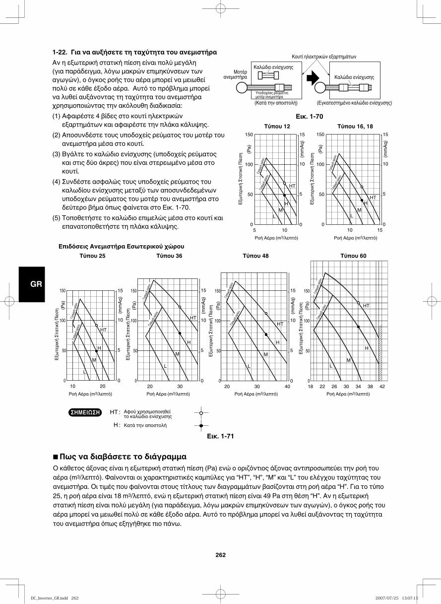
GB
FR
DE
IT
PT
GR
ES
262
5
Ροή Αέρα (m3/λεπτό)Ροή Αέρα (m3/λεπτό)
0
50
100
0
5
10
15 150
10
(mm
Aq)
(Pa)
Γραμμή
ορίου
Γραμ
μή ορ
ίου
HT
H M
L
20
Ροή Αέρα (m3/λεπτό) Ροή Αέρα (m3/λεπτό) Ροή Αέρα (m3/λεπτό)Ροή Αέρα (m3/λεπτό)
0
50
0
5
10
15 150
10
HT
H
L
100
M
(mm
Aq)
(Pa)
30 40 18 22 26 30 34 38 42 0
50
0
5
10
15 150
20
L
100
M
H
M
H
L
(mm
Aq)
(Pa)
0
50
150
100
(Pa)
HT
HT
30 0
50
0
5
10
15 150
20
HT
L
100
M
H
(mm
Aq)
(Pa)
15 0
50
0
5
10
15 150
10
Γραμμή
ορίου
Γραμ
μή ορ
ίου
HT
M L
100
H
(mm
Aq)
(Pa)
Τύπου 16, 18Τύπου 12
Επιδόσεις Ανεμιστήρα Εσωτερικού χώρουΤύπου 25 Τύπου 36 Τύπου 48 Τύπου 60
Εξωτ
ερική
Στατ
ική Π
ίεση
Εξωτ
ερική
Στατ
ική Π
ίεση
Εξωτ
ερική
Στατ
ική Π
ίεση
Εξωτ
ερική
Στατ
ική Π
ίεση
Εξωτ
ερική
Στατ
ική Π
ίεση
Εξωτ
ερική
Στατ
ική Π
ίεση
Γραμ
μή ορ
ίουΓρα
μμή ο
ρίου
Γραμμ
ή ορίο
υΓρα
μμή ορ
ίου
Γραμμή
ορίου
Γραμμή
ορίου
Γραμμ
ή ορίο
υΓρα
μμή ορ
ίου
HT : Αφού χρησιμοποιηθεί το καλώδιο ενίσχυσης
H : Κατά την αποστολή
ΣΗΜΕΙΩΣΗ
1-22. Για να αυξήσετε τη ταχύτητα του ανεμιστήραΑν η εξωτερική στατική πίεση είναι πολύ μεγάλη (για παράδειγμα, λόγω μακρών επιμηκύνσεων των αγωγών), ο όγκος ροής του αέρα μπορεί να μειωθεί πολύ σε κάθε έξοδο αέρα. Αυτό το πρόβλημα μπορεί να λυθεί αυξάνοντας τη ταχύτητα του ανεμιστήρα χρησιμοποιώντας την ακόλουθη διαδικασία:(1) Αφαιρέστε 4 βίδες στο κουτί ηλεκτρικών
εξαρτημάτων και αφαιρέστε την πλάκα κάλυψης.(2) Αποσυνδέστε τους υποδοχείς ρεύματος του μοτέρ του
ανεμιστήρα μέσα στο κουτί.(3) Βγάλτε το καλώδιο ενίσχυσης (υποδοχείς ρεύματος
και στις δύο άκρες) που είναι στερεωμένο μέσα στο κουτί.
(4) Συνδέστε ασφαλώς τους υποδοχείς ρεύματος του καλωδίου ενίσχυσης μεταξύ των αποσυνδεδεμένων υποδοχέων ρεύματος του μοτέρ του ανεμιστήρα στο δεύτερο βήμα όπως φαίνεται στο Εικ. 1-70.
(5) Τοποθετήστε το καλώδιο επιμελώς μέσα στο κουτί και επανατοποθετήστε τη πλάκα κάλυψης.
Εικ. 1-70
Εικ. 1-71
Καλώδιο ενίσχυσηςΚαλώδιο ενίσχυσης
Κουτί ηλεκτρικών εξαρτημάτων
(Κατά την αποστολή) (Εγκατεστημένο καλώδιο ενίσχυσης)Υποδοχέας ρεύματοςμοτέρ ανεμιστήρα
Μοτέρανεμιστήρα
■ Πως να διαβάσετε το διάγραμμαΟ κάθετος άξονας είναι η εξωτερική στατική πίεση (Pa) ενώ ο οριζόντιος άξονας αντιπροσωπεύει την ροή του αέρα (m3/λεπτό). Φαίνονται οι χαρακτηριστικές καμπύλες για “ΗΤ”, “Η”, “Μ” και “L” του ελέγχου ταχύτητας του ανεμιστήρα. Οι τιμές που φαίνονται στους τίτλους των διαγραμμάτων βασίζονται στη ροή αέρα “H”. Για το τύπο 25, η ροή αέρα είναι 18 m3/λεπτό, ενώ η εξωτερική στατική πίεση είναι 49 Pa στη θέση “H”. Αν η εξωτερική στατική πίεση είναι πολύ μεγάλη (για παράδειγμα, λόγω μακρών επιμηκύνσεων των αγωγών), ο όγκος ροής του αέρα μπορεί να μειωθεί πολύ σε κάθε έξοδο αέρα. Αυτό το πρόβλημα μπορεί να λυθεί αυξάνοντας τη ταχύτητα του ανεμιστήρα όπως εξηγήθηκε πιο πάνω.
DC_Inverter_GR.indd 262DC_Inverter_GR.indd 262 2007/07/25 13:07:152007/07/25 13:07:15
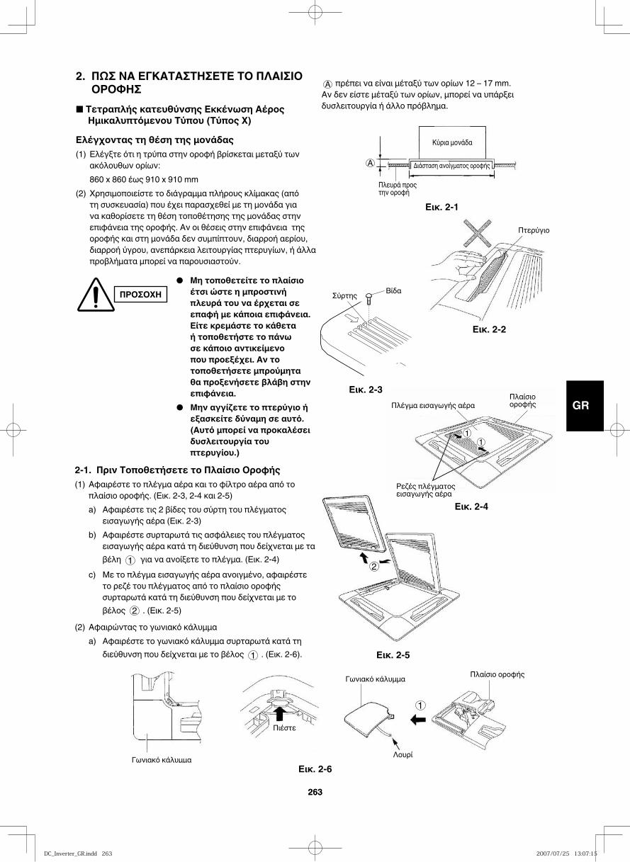
GB
FR
DE
IT
PT
GR
ES
263263
2. ΠΩΣ ΝΑ ΕΓΚΑΤΑΣΤΗΣΕΤΕ ΤΟ ΠΛΑΙΣΙΟ ΟΡΟΦΗΣ
■ Τετραπλής κατευθύνσης Εκκένωση Αέρος Ημικαλυπτόμενου Τύπου (Τύπος X)
Ελέγχοντας τη θέση της μονάδας(1) Ελέγξτε ότι η τρύπα στην οροφή βρίσκεται μεταξύ των
ακόλουθων ορίων: 860 x 860 έως 910 x 910 mm(2) Χρησιμοποιείστε το διάγραμμα πλήρους κλίμακας (από
τη συσκευασία) που έχει παρασχεθεί με τη μονάδα για να καθορίσετε τη θέση τοποθέτησης της μονάδας στην επιφάνεια της οροφής. Αν οι θέσεις στην επιφάνεια της οροφής και στη μονάδα δεν συμπίπτουν, διαρροή αερίου, διαρροή ύγρου, ανεπάρκεια λειτουργίας πτερυγίων, ή άλλα προβλήματα μπορεί να παρουσιαστούν.
ΠΡΟΣΟΧΗ● Μη τοποθετείτε το πλαίσιο
έτσι ώστε η μπροστινή πλευρά του να έρχεται σε επαφή με κάποια επιφάνεια. Είτε κρεμάστε το κάθετα ή τοποθετήστε το πάνω σε κάποιο αντικείμενο που προεξέχει. Αν το τοποθετήσετε μπρούμητα θα προξενήσετε βλάβη στην επιφάνεια.
● Μην αγγίζετε το πτερύγιο ή εξασκείτε δύναμη σε αυτό. (Αυτό μπορεί να προκαλέσει δυσλειτουργία του πτερυγίου.)
A πρέπει να είναι μέταξύ των ορίων 12 – 17 mm.Αν δεν είστε μέταξύ των ορίων, μπορεί να υπάρξει δυσλειτουργία ή άλλο πρόβλημα.
Πλευρά προς την οροφή
Κύρια μονάδα
Διάσταση ανοίγματος οροφήςA
Εικ. 2-1
Πτερύγιο
Εικ. 2-2
Εικ. 2-3
2
Εικ. 2-5
2-1. Πριν Τοποθετήσετε το Πλαίσιο Οροφής(1) Αφαιρέστε το πλέγμα αέρα και το φίλτρο αέρα από το
πλαίσιο οροφής. (Εικ. 2-3, 2-4 και 2-5)a) Αφαιρέστε τις 2 βίδες του σύρτη του πλέγματος
εισαγωγής αέρα (Εικ. 2-3)b) Αφαιρέστε συρταρωτά τις ασφάλειες του πλέγματος
εισαγωγής αέρα κατά τη διεύθυνση που δείχνεται με τα βέλη 1 για να ανοίξετε το πλέγμα. (Εικ. 2-4)
c) Με το πλέγμα εισαγωγής αέρα ανοιγμένο, αφαιρέστε το ρεζέ του πλέγματος από το πλαίσιο οροφής συρταρωτά κατά τη διεύθυνση που δείχνεται με το βέλος 2 . (Εικ. 2-5)
(2) Αφαιρώντας το γωνιακό κάλυμμαa) Αφαιρέστε το γωνιακό κάλυμμα συρταρωτά κατά τη
διεύθυνση που δείχνεται με το βέλος 1 . (Εικ. 2-6).
Γωνιακό κάλυμμα
Πλαίσιο οροφής
Λουρί
Πιέστε
1
Γωνιακό κάλυμμα
Εικ. 2-6
Πλέγμα εισαγωγής αέραΠλαίσιο οροφής
Ρεζές πλέγματος εισαγωγής αέρα
11
Εικ. 2-4
Σύρτης Βίδα
DC_Inverter_GR.indd 263DC_Inverter_GR.indd 263 2007/07/25 13:07:152007/07/25 13:07:15
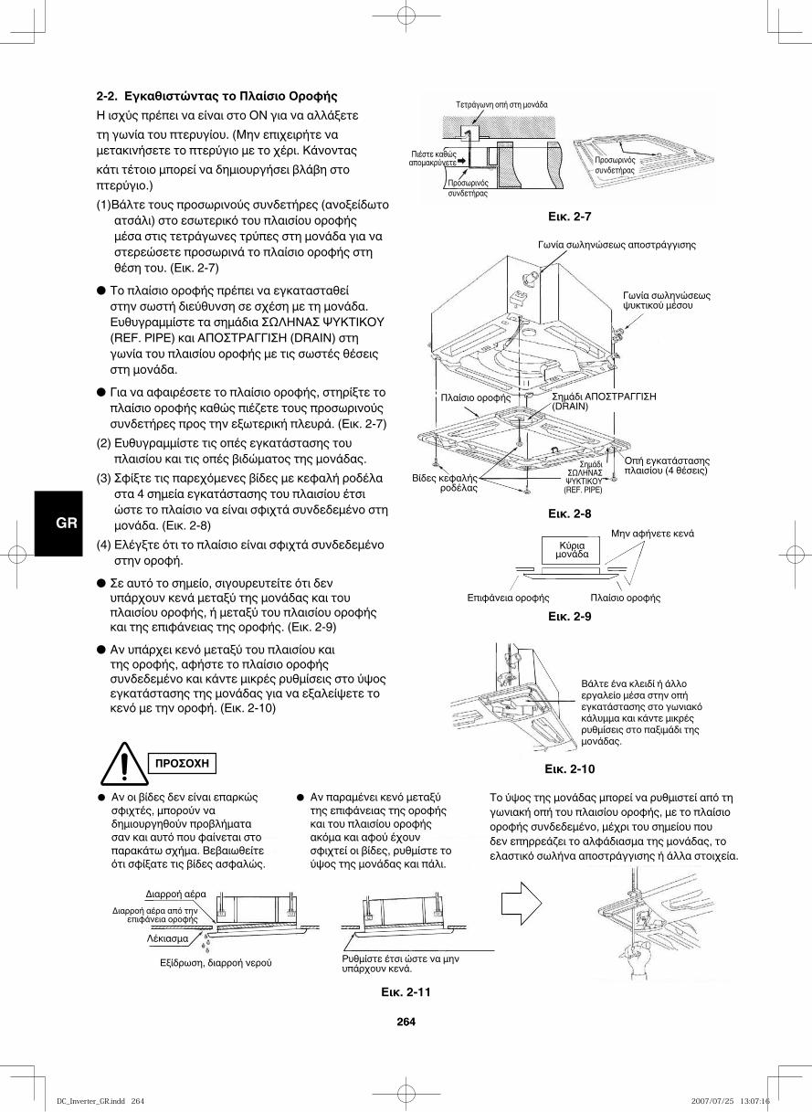
GB
FR
DE
IT
PT
GR
ES
264264
ΠΡΟΣΟΧΗ
2-2. Εγκαθιστώντας το Πλαίσιο ΟροφήςΗ ισχύς πρέπει να είναι στο ΟΝ για να αλλάξετε τη γωνία του πτερυγίου. (Μην επιχειρήτε να μετακινήσετε το πτερύγιο με το χέρι. Κάνοντας κάτι τέτοιο μπορεί να δημιουργήσει βλάβη στο πτερύγιο.)(1)Βάλτε τους προσωρινούς συνδετήρες (ανοξείδωτο
ατσάλι) στο εσωτερικό του πλαισίου οροφής μέσα στις τετράγωνες τρύπες στη μονάδα για να στερεώσετε προσωρινά το πλαίσιο οροφής στη θέση του. (Εικ. 2-7)
● Το πλαίσιο οροφής πρέπει να εγκατασταθεί στην σωστή διεύθυνση σε σχέση με τη μονάδα. Ευθυγραμμίστε τα σημάδια ΣΩΛΗΝΑΣ ΨΥΚΤΙΚΟΥ (REF. PIPE) και ΑΠΟΣΤΡΑΓΓΙΣΗ (DRAIN) στη γωνία του πλαισίου οροφής με τις σωστές θέσεις στη μονάδα.
● Για να αφαιρέσετε το πλαίσιο οροφής, στηρίξτε το πλαίσιο οροφής καθώς πιέζετε τους προσωρινούς συνδετήρες προς την εξωτερική πλευρά. (Εικ. 2-7)
(2) Ευθυγραμμίστε τις οπές εγκατάστασης του πλαισίου και τις οπές βιδώματος της μονάδας.
(3) Σφίξτε τις παρεχόμενες βίδες με κεφαλή ροδέλα στα 4 σημεία εγκατάστασης του πλαισίου έτσι ώστε το πλαίσιο να είναι σφιχτά συνδεδεμένο στη μονάδα. (Εικ. 2-8)
(4) Ελέγξτε ότι το πλαίσιο είναι σφιχτά συνδεδεμένο στην οροφή.
● Σε αυτό το σημείο, σιγουρευτείτε ότι δεν υπάρχουν κενά μεταξύ της μονάδας και του πλαισίου οροφής, ή μεταξύ του πλαισίου οροφής και της επιφάνειας της οροφής. (Εικ. 2-9)
● Αν υπάρχει κενό μεταξύ του πλαισίου και της οροφής, αφήστε το πλαίσιο οροφής συνδεδεμένο και κάντε μικρές ρυθμίσεις στο ύψος εγκατάστασης της μονάδας για να εξαλείψετε το κενό με την οροφή. (Εικ. 2-10)
Τετράγωνη οπή στη μονάδα
Προσωρινός συνδετήρας
Πιέστε καθώς απομακρύνετε Προσωρινός
συνδετήρας
Εικ. 2-7
Γωνία σωληνώσεως αποστράγγισης
Γωνία σωληνώσεως ψυκτικού μέσου
Οπή εγκατάστασης πλαισίου (4 θέσεις)
Πλαίσιο οροφής
Βίδες κεφαλής ροδέλας
Σημάδι ΑΠΟΣΤΡΑΓΓΙΣΗ (DRAIN)
Σημάδι ΣΩΛΗΝΑΣ
ΨΥΚΤΙΚΟΥ (REF. PIPE)
Εικ. 2-8Μην αφήνετε κενά
Πλαίσιο οροφής
Κύριαμονάδα
Επιφάνεια οροφήςΕικ. 2-9
Βάλτε ένα κλειδί ή άλλο εργαλείο μέσα στην οπή εγκατάστασης στο γωνιακό κάλυμμα και κάντε μικρές ρυθμίσεις στο παξιμάδι της μονάδας.
Διαρροή αέραΔιαρροή αέρα από την
επιφάνεια οροφής
Λέκιασμα
Εξίδρωση, διαρροή νερού Ρυθμίστε έτσι ώστε να μην υπάρχουν κενά.
Εικ. 2-10
Εικ. 2-11
● Αν οι βίδες δεν είναι επαρκώς σφιχτές, μπορούν να δημιουργηθούν προβλήματα σαν και αυτό που φαίνεται στο παρακάτω σχήμα. Βεβαιωθείτε ότι σφίξατε τις βίδες ασφαλώς.
● Αν παραμένει κενό μεταξύ της επιφάνειας της οροφής και του πλαισίου οροφής ακόμα και αφού έχουν σφιχτεί οι βίδες, ρυθμίστε το ύψος της μονάδας και πάλι.
Το ύψος της μονάδας μπορεί να ρυθμιστεί από τη γωνιακή οπή του πλαισίου οροφής, με το πλαίσιο οροφής συνδεδεμένο, μέχρι του σημείου που δεν επηρρεάζει το αλφάδιασμα της μονάδας, το ελαστικό σωλήνα αποστράγγισης ή άλλα στοιχεία.
DC_Inverter_GR.indd 264DC_Inverter_GR.indd 264 2007/07/25 13:07:162007/07/25 13:07:16
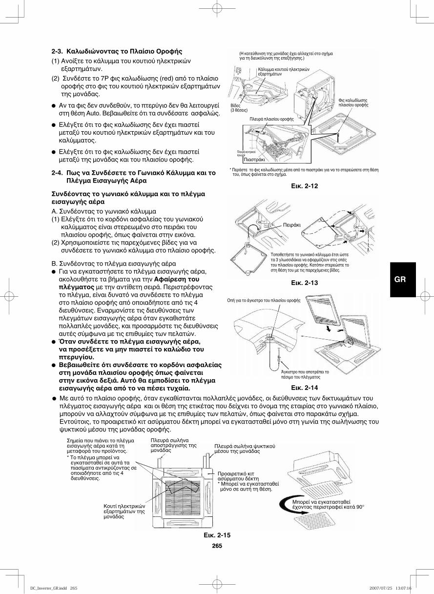
GB
FR
DE
IT
PT
GR
ES
265265
2-3. Καλωδιώνοντας το Πλαίσιο Οροφής(1) Ανοίξτε το κάλυμμα του κουτιού ηλεκτρικών
εξαρτημάτων.(2) Συνδέστε το 7P φις καλωδίωσης (red) από το πλαίσιο
οροφής στο φις του κουτιού ηλεκτρικών εξαρτημάτων της μονάδας.
● Αν τα φις δεν συνδεθούν, το πτερύγιο δεν θα λειτουργεί στη θέση Auto. Βεβαιωθείτε ότι τα συνδέσατε ασφαλώς.
● Ελέγξτε ότι το φις καλωδίωσης δεν έχει πιαστεί μεταξύ του κουτιού ηλεκτρικών εξαρτημάτων και του καλύμματος.
● Ελέγξτε ότι το φις καλωδίωσης δεν έχει πιαστεί μεταξύ της μονάδας και του πλαισίου οροφής.
2-4. Πως να Συνδέσετε το Γωνιακό Κάλυμμα και το Πλέγμα Εισαγωγής Αέρα
Συνδέοντας το γωνιακό κάλυμμα και το πλέγμα εισαγωγής αέραA. Συνδέοντας το γωνιακό κάλυμμα(1) Ελέγξτε ότι το κορδόνι ασφαλείας του γωνιακού
καλύμματος είναι στερεωμένο στο πειράκι του πλαισίου οροφής, όπως φαίνεται στην εικόνα.
(2) Χρησιμοποιείστε τις παρεχόμενες βίδες για να συνδέσετε το γωνιακό κάλυμμα στο πλαίσιο οροφής.
B. Συνδέοντας το πλέγμα εισαγωγής αέρα● Για να εγκαταστήσετε το πλέγμα εισαγωγής αέρα, ακολουθήστε τα βήματα για την Αφαίρεση του πλέγματος με την αντίθετη σειρά. Περιστρέφοντας το πλέγμα, είναι δυνατό να συνδέσετε το πλέγμα στο πλαίσιο οροφής από οποιαδήποτε από τις 4 διευθύνσεις. Εναρμονίστε τις διευθύνσεις των πλεγμάτων εισαγωγής αέρα όταν εγκαθιστάτε πολλαπλές μονάδες, και προσαρμόστε τις διευθύνσεις αυτές σύμφωνα με τις επιθυμίες των πελατών.
● Όταν συνδέετε το πλέγμα εισαγωγής αέρα, να προσέξετε να μην πιαστεί το καλώδιο του πτερυγίου.
● Βεβαιωθείτε ότι συνδέσατε το κορδόνι ασφαλείας στη μονάδα πλαισίου οροφής όπως φαίνεται στην εικόνα δεξιά. Αυτό θα εμποδίσει το πλέγμα εισαγωγής αέρα από το να πέσει τυχαία.
(Η κατεύθυνση της μονάδας έχει αλλαχτεί στο σχήμα για τη διευκόλυνση της επεξήγησης.)
Φις καλωδίωσης πλαισίου οροφής
Πλευρά πλαισίου οροφής
Βίδες(3 θέσεις)
Πιαστράκι
Κάλυμμα κουτιού ηλεκτρικών εξαρτημάτων
* Περάστε το φις καλωδίωσης μέσα από το πιαστράκι για να το στερεώσετε στη θέση του, όπως φαίνεται στο σχήμα.
Πλευρά κεντρικούαγωγού
Τοποθετήστε το γωνιακό κάλυμμα έτσι ώστε τα 3 γλωσσιδάκια να εφαρμόζουν στις οπές του πλαισίου οροφής. Κατόπιν στερεώστε το στη θέση του με τις παρεχόμενες βίδες.
Πειράκι
● Με αυτό το πλαίσιο οροφής, όταν εγκαθίστανται πολλαπλές μονάδες, οι διεύθυνσεις των δικτυωμάτων του πλέγματος εισαγωγής αέρα και οι θέση της ετικέτας που δείχνει το όνομα της εταιρίας στο γωνιακό πλαίσιο, μπορούν να αλλαχτούν σύμφωνα με τις επιθυμίες των πελατών, όπως φαίνεται στο παρακάτω σχήμα. Εντούτοις, το προαιρετικό κιτ ασύρματου δέκτη μπορεί να εγκατασταθεί μόνο στη γωνία της σωλήνωσης του ψυκτικού μέσου της μονάδας οροφής.
Κουτί ηλεκτρικών εξαρτημάτων της μονάδας
Πλευρά σωλήνα αποστράγγισης της μονάδας Πλευρά σωλήνα ψυκτικού
μέσου της μονάδας
Προαιρετικό κιτ ασύρματου δέκτη* Μπορεί να εγκατασταθεί μόνο σε αυτή τη θέση.
Μπορεί να εγκατασταθεί έχοντας περιστραφεί κατά 90°
Σημεία που πιάνει το πλέγμα εισαγωγής αέρα κατά τη μεταφορά του προϊόντος.* Το πλέγμα μπορεί να
εγκατασταθεί σε αυτά τα πιασίματα αντικρύζοντας σε οποιαδήποτε από τις 4 διευθύνσεις.
Εικ. 2-12
Εικ. 2-13
Οπή για το άγκιστρο του πλαισίου οροφής
Άγκιστρο που αποτρέπει το πέσιμο του πλέγματος
Εικ. 2-14
Εικ. 2-15
DC_Inverter_GR.indd 265DC_Inverter_GR.indd 265 2007/07/25 13:07:162007/07/25 13:07:16
GB
FR
DE
IT
PT
GR
ES
266266
2-5. Έλεγχος Μετά την Εγκατάσταση● Ελέγξτε ότι δεν υπάρχουν κενά μεταξύ της μονάδας και του πλαισίου οροφής, ή μεταξύ του πλαισίου οροφής και της επιφάνειας οροφής. Τυχόν κενά μπορεί να προκαλέσουν διαρροή νερού ή εξίδρωση.
● Ελέγξτε ότι η καλωδιώσεις είναι ασφαλώς συνδεδεμένες. Αν δεν είναι συνδεδεμένες ασφαλώς, η αυτόματη λειτουργία του πτερυγίου δεν θα είναι διαθέσιμη. (“P09” θα εμφανίζεται στο τηλεχειριστήριο.) Επιπρόσθετα, διαρροή νερού και εξίδρωση μπορεί να εμφανιστούν.
2-6. Αφαιρώντας το Πλαίσιο Οροφής για Συντήρηση
Όταν αφαιρείτε το πλαίσιο οροφής για συντήρηση, αφαιρέστε το πλέγμα εισαγωγής αέρα και το φίλτρο αέρα, αποσυνδέστε το φις της καλωδίωσης μέσα στο κουτί ηλεκτρικών εξαρτημάτων και έπειτα αφαιρέστε τις 4 βίδες τοποθέτησης.
2-7. Ρυθμίζοντας την Αυτόματη Λειτουργία του Πτερυγίου
Η περσίδα κατεύθυνσης του αέρα στο στόμιο του πλαισίου οροφής μπορεί να ρυθμιστεί ως ακολούθως.● Ρυθμίστε τη περσίδα στην επιθυμητή γωνία χρησιμοποιώντας το τηλεχειριστήριο.
ΣΗΜΕΙΩΣΗ● Μην επιχειρείτε ποτέ να μετακινήσετε την περσίδα με το χέρι.
● Η σωστή ροή του αέρα εξαρτάται από το κλιματιστικό, τη διαρρύθμιση του δωματίου και των επίπλων, κλπ. Εάν η ψύξη ή η θέρμανση μοιάζει ανεπαρκής, δοκιμάστε να αλλάξετε τη διεύθυνση της ροής του αέρα.
DC_Inverter_GR.indd 266DC_Inverter_GR.indd 266 2007/07/25 13:07:172007/07/25 13:07:17
267
ES
¡IMPOR TAN TE!Por favor, lea antes de comen zar
Este sis te ma acon di cio na dor de aire satis fa ce estric tos están da res de segu ri dad y ope ra ción. Como ins ta la dor o per so na de man te ni mien to, es una parte impor tan te de su tra ba jo ins ta lar o efec tuar el man te ni mien to del sis te ma de mane ra que opere de forma segu ra y efi cien te.
Para la ins ta la ción segu ra y ope ra ción libre de fallas, usted debe:
● Leer cui da do sa men te este manual de ins truc cio nes antes de comen zar.
● Seguir cada paso de ins ta la ción o repa ra ción exac ta men te de la mane ra que se indi ca.
● Res pe te todos los códi gos eléc tri cos loca les, esta ta les y nacio na les.
● Este producto está destinado para usos profesionales.Se necesita permiso del distribuidor de energía eléctrica cuando se instale una unidad exterior que vaya conectada a una red de distribución de 16 A.
● Ponga espe cial aten ción en todas las noti fi ca cio nes de adver ten cia y pre cau ción que se dan en este manual.
Este sím bo lo se refie re a prác ti cas peli gro sas o inse gu ras que pue den resul tar en lesio nes per so na les gra ves o muer te.
Este sím bo lo se refie re a prác ti cas peli gro sas o inse gu ras que pue den resul tar en lesio nes per so na les o daño al pro duc to o la pro pie dad.
Si es nece sa rio, obten ga ayudaEstas ins truc cio nes son todo lo que usted nece si ta para la mayo ría de los luga res de ins ta la ción y con di cio nes de man te ni mien to. Si usted requie re ayuda para un pro ble ma espe cial, con tac te a algu nos de nues tros cen tros de venta/ser vi cio o a su dis tri bui dor cer ti fi ca do para ins truc cio nes adi cio na les.
En caso de ins ta la ción inade cua daEl fabri can te no será res pon sa ble en nin gún modo por la ins ta la ción o ser vi cio de man te ni mien to inade cua do, inclu yen do el no seguir las ins truc cio nes en este docu men to.
PRE CAU CIO NES ESPE CIA LES
ADVERTENCIA Duran te el cable a do
UN CHO QUE ELÉC TRI CO PUEDE CAU SAR GRA VES LESIO NES PER SO NA LES O MUER TE. SÓLO UN ELEC TRI CIS TA CALI FI CA DO Y EXPE RI MEN TA DO DEBE EFEC TUAR EL CABLE A DO DE ESTE SIS TE MA.
• No ali men te la uni dad hasta que todos los cable a dos y tube rí as hayan sido com ple ta dos o reco nec ta dos y veri fi ca dos.
• Se uti li zan vol ta jes eléc tri cos alta men te peli gro sos en este sis te ma. Refié ra se cui da do sa men te al dia gra ma de cable a do y a estas ins truc cio nes cuan do efec túe el cable a do. Las cone xio nes impro pias o cone xión a tie rra inade cua da pue den cau sar lesio nes o muer te acci den tal.
• Conec te la uni dad a tie rra siguien do los códi gos eléc tri cos loca les.
• Conec te fir me men te todos los cables. Los cables suel tos pue den cau sar sobre ca len ta mien to en los pun tos de cone xión y posi ble peli gro de incen dio.
Duran te el trans por te
Sea cui da do so cuan do levan te y trans por te las uni da des inter na y exter na. Con si ga un ayu dan te, y doble sus rodi llas cuan do levan te para redu cir el esfuer zo de su espal da. Los bor des agu dos y las ale tas de alu mi nio del ga das en el acon di cio na dor de aire pue den cor tar sus dedos.
Duran te la ins ta la ción…
…En una sala
Aisle apro pia da men te cual quier tube ría que corra por el inte rior de la sala para pre ve nir “trans pi ra ción” que puede cau sar goteo y daño por agua en las pare des y pisos.
…En luga res húme dos o irre gu la res
Use una base de con cre to o blo ques de con cre to para pro ve er una fun da ción sóli da y nive la da para la uni dad exter na. Esto evita el daño por agua y vibra cio nes anor ma les.
…En áreas expues tas al vien to fuer te
Ancle segu ra men te la uni dad exter na con per nos y un bas ti dor metá li co. Pro vea un deflec tor de aire ade cua do.
… En áreas expues tas a la nieve (para sis te mas de tipo bomba de calen ta mien to)
Ins ta le la uni dad exter na sobre una pla ta for ma levan ta da que sea más alta que la nieve arras tra da. Pro vea ori fi cios para la nieve.
Al conec tar la tube ría de refri ge ran te
• Ventile bien la habitación por si se produjeran fugas de gas refrigerante durante la instalación. Tenga cuidado de que el gas refrigerante no se ponga en contacto con fuego por causaría la generación de gas venenoso.
• Mantenga todas las tuberías lo más cortas que sea posible.
• Use el méto do de abo ci na mien to para la tube ría de cone xión.
• Apli que lubri can te de refri ge ran te a las super fi cies en con tac to de la boci na y los tubos de unión antes de conec tar los, luego aprie te la tuer ca con una llave de tor sión para lograr una cone xión libre de fil tra cio nes.
• Veri fi que cui da do sa men te la exis ten cia de fil tra cio nes antes de arran car la ope ra ción de prue ba.
Duran te el man te ni mien to
• Apa gue la uni dad desde la caja de ali men ta ción prin ci pal antes de abrir la uni dad para veri fi car o repa rar par tes eléc tri cas y cable a dos.
• Man ten ga sus dedos y ropa lejos de las par tes móvi les.
• Lim pie el lugar des pués de ter mi nar, recor dan do de veri fi car que no que den res tos metá li cos ni peda ci tos de alam bre den tro de la uni dad some ti da a man te ni mien to.
• Ven ti le las áreas ence rra das cuan do efec túe la ins ta la ción o prue-ba del sis te ma de refri ge ra ción. El gas refri ge ran te que esca pa, en con tac to con el fuego o el calor, puede pro du cir gases tóxi cos peli gro sos.
• Después de la instalación, confirme que no haya fugas de gas refrigerante. Si el gas se pone en contacto con una estufa de combustión, estufa de agua calentada con gas, u otra fuente de calor, puede generarse gas venenoso.
ADVERTENCIA
PRECAUCIÓN
PRECAUCIÓN
DC_Inverter_SP.indd 267DC_Inverter_SP.indd 267 2007/07/25 12:21:342007/07/25 12:21:34
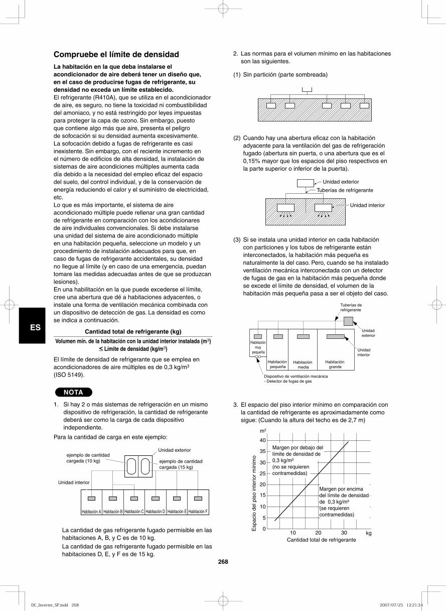
268
ES
2. Las normas para el volumen mínimo en las habitaciones son las siguientes.
(1) Sin partición (parte sombreada)
(2) Cuando hay una abertura eficaz con la habitación adyacente para la ventilación del gas de refrigeración fugado (abertura sin puerta, o una abertura que es el 0,15% mayor que los espacios del piso respectivos en la parte superior o inferior de la puerta).
(3) Si se instala una unidad interior en cada habitación con particiones y los tubos de refrigerante están interconectados, la habitación más pequeña es naturalmente la del caso. Pero, cuando se ha instalado ventilación mecánica interconectada con un detector de fugas de gas en la habitación más pequeña donde se excede el límite de densidad, el volumen de la habitación más pequeña pasa a ser el objeto del caso.
3. El espacio del piso interior mínimo en comparación con la cantidad de refrigerante es aproximadamente como sigue: (Cuando la altura del techo es de 2,7 m)
40
35
30
25
20
15
10
5
010 20 30
Cantidad total de refrigerante
Esp
acio
del
pis
o in
terio
r m
ínim
o
m2
kg
Margen por debajo del límite de densidad de 0,3 kg/m³ (no se requieren contramedidas)
Margen por encima del límite de densidad de 0,3 kg/m³ (se requieren contramedidas)
Compruebe el límite de densidadLa habitación en la que deba instalarse el acondicionador de aire deberá tener un diseño que, en el caso de producirse fugas de refrigerante, su densidad no exceda un límite establecido.El refrigerante (R410A), que se utiliza en el acondicionador de aire, es seguro, no tiene la toxicidad ni combustibilidad del amoniaco, y no está restringido por leyes impuestas para proteger la capa de ozono. Sin embargo, puesto que contiene algo más que aire, presenta el peligro de sofocación si su densidad aumenta excesivamente. La sofocación debido a fugas de refrigerante es casi inexistente. Sin embargo, con el reciente incremento en el número de edificios de alta densidad, la instalación de sistemas de aire acondiciones múltiples aumenta cada día debido a la necesidad del empleo eficaz del espacio del suelo, del control individual, y de la conservación de energía reduciendo el calor y el suministro de electricidad, etc.Lo que es más importante, el sistema de aire acondicionado múltiple puede rellenar una gran cantidad de refrigerante en comparación con los acondicionares de aire individuales convencionales. Si debe instalarse una unidad del sistema de aire acondicionado múltiple en una habitación pequeña, seleccione un modelo y un procedimiento de instalación adecuados para que, en caso de fugas de refrigerante accidentales, su densidad no llegue al límite (y en caso de una emergencia, puedan tomare las medidas adecuadas antes de que se produzcan lesiones).En una habilitación en la que puede excederse el límite, cree una abertura que dé a habitaciones adyacentes, o instale una forma de ventilación mecánica combinada con un dispositivo de detección de gas. La densidad es como se indica a continuación.
Cantidad total de refrigerante (kg)
Volumen mín. de la habitación con la unidad interior instalada (m3)< Límite de densidad (kg/m3)
El límite de densidad de refrigerante que se emplea en acondicionadores de aire múltiples es de 0,3 kg/m3 (ISO 5149).
NOTA
1. Si hay 2 o más sistemas de refrigeración en un mismo dispositivo de refrigeración, la cantidad de refrigerante deberá ser como la carga de cada dispositivo independiente.
Para la cantidad de carga en este ejemplo:
La cantidad de gas refrigerante fugado permisible en las habitaciones A, B, y C es de 10 kg.La cantidad de gas refrigerante fugado permisible en las habitaciones D, E, y F es de 15 kg.
Unidad exterior
Tuberías de refrigerante
Unidad interior
ejemplo de cantidad cargada (10 kg)
Unidad exterior
Unidad interior
Habitación A
ejemplo de cantidad cargada (15 kg)
Habitación B Habitación C Habitación D Habitación E Habitación F
Habitación muy
pequeña
Habitación pequeña
Habitación media
Dispositivo de ventilación mecánica - Detector de fugas de gas
Habitación grande
Unidad interior
Unidad exterior
Tuberías de refrigerante
DC_Inverter_SP.indd 268DC_Inverter_SP.indd 268 2007/07/25 12:21:342007/07/25 12:21:34
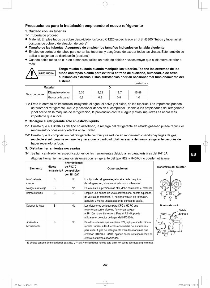
ES
1-2. Evite la entrada de impurezas incluyendo el agua, el polvo y el óxido, en las tuberías. Las impurezas pueden deteriorar el refrigerante R410A y ocasionar daños en el compresor. Debido a las propiedades del refrigerante y del aceite de la máquina de refrigeración, la prevención contra el agua y otras impurezas es ahora más importante que nunca.
2. Recargue el refrigerante sólo en estado líquido.
2-1. Puesto que el R410A es del tipo no azeótropo, la recarga del refrigerante en estado gaseoso puede reducir el rendimiento y ocasionar defectos en la unidad.
2-2. Puesto que la composición del refrigerante cambia y se reduce en rendimiento cuando hay fugas de gas, recolecte el refrigerante remanente y recargue la cantidad total necesaria de nuevo refrigerante después de haber reparado la fuga.
3. Distintas herramientas necesarias
3-1. Se han cambiado las especificaciones de las herramientas debido a las características del R410A.
Algunas herramientas para los sistemas con refrigerante del tipo R22 y R407C no pueden utilizarse.
Precauciones para la instalación empleando el nuevo refrigerante 1. Cuidado con las tuberías1-1. Tubería de proceso● Material: Emplee tubos de cobre desoxidado fosforoso C1220 especificado en JIS H3300 “Tubos y tuberías sin
costuras de cobre o de aleación de cobre”.● Tamaño de las tuberías: Asegúrese de emplear los tamaños indicados en la tabla siguiente.● Emplee un cortador de tubos para cortar las tuberías, y asegúrese de extraer todas las virutas. Esto también se
aplica a las juntas de distribución (opcional).● Cuando doble tubos de ø15,88 o menores, utilice un radio de doblez 4 veces mayor que el diámetro exterior o
más.
Manómetro del colector
Bomba de vacio
SalidaEntrada
PRECAUCIÓN
Tenga mucho cuidado cuando manipule las tuberías. Tapone los extremos de los tubos con tapas o cinta para evitar la entrada de suciedad, humedad, o de otras substancias extrañas. Estas substancias podrían ocasionar mal funcionamiento del sistema.
Material O
Tubo de cobre Diámetro exterior 6,35 9,52 12,7 15,88
Grosor de la pared 0,8 0,8 0,8 1,0
Unidad: mm
¿Herramientas
Elemento ¿Nueva de R407C
Observaciones herramienta? compatibles con R410A?
Manómetro del Sí No Los tipos de refrigerantes, el aceite de la máquina colector de refrigeración, y los manómetros son diferentes.
Manguera de carga Sí No Para resistir la presión más alta, debe cambiarse el material
Bomba de vacío Sí Sí Emplee una bomba de vacío convencional si está equipada de válvula de retención. Si no tiene válvula de retención, adquiera y monte un adaptador de bomba de vacío.
Detector de fugas Sí No Los detectores de fugas para CFC y HCFC que reaccionan con el cloro no funcionan porque el R410A no contiene cloro. Para el R410A puede utilizarse el detector de fugas del HFC134a.
Aceite de a Sí No Para los sistemas que emplean R22, aplique aceite mineral bocinamiento (aceite Suniso) a las tuercas abocinadas de las tuberías para evitar fugas del refrigerante. Para las máquinas que emplean R407C o R410A, aplique aceite sintético (aceite de éter) a las tuercas abocinadas.
* El empleo conjunto de herramientas para R22 y R407C y herramientas nuevas para el R410A puede ser causa de problemas.
269
DC_Inverter_SP.indd 269DC_Inverter_SP.indd 269 2007/07/25 12:21:342007/07/25 12:21:34
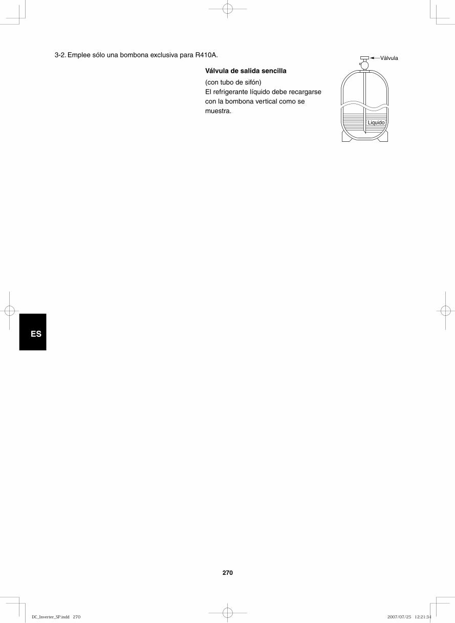
270
ES
Vàlvula
Liquido
3-2. Emplee sólo una bombona exclusiva para R410A.
Válvula de salida sencilla
(con tubo de sifón)El refrigerante líquido debe recargarse con la bombona vertical como se muestra.
DC_Inverter_SP.indd 270DC_Inverter_SP.indd 270 2007/07/25 12:21:342007/07/25 12:21:34
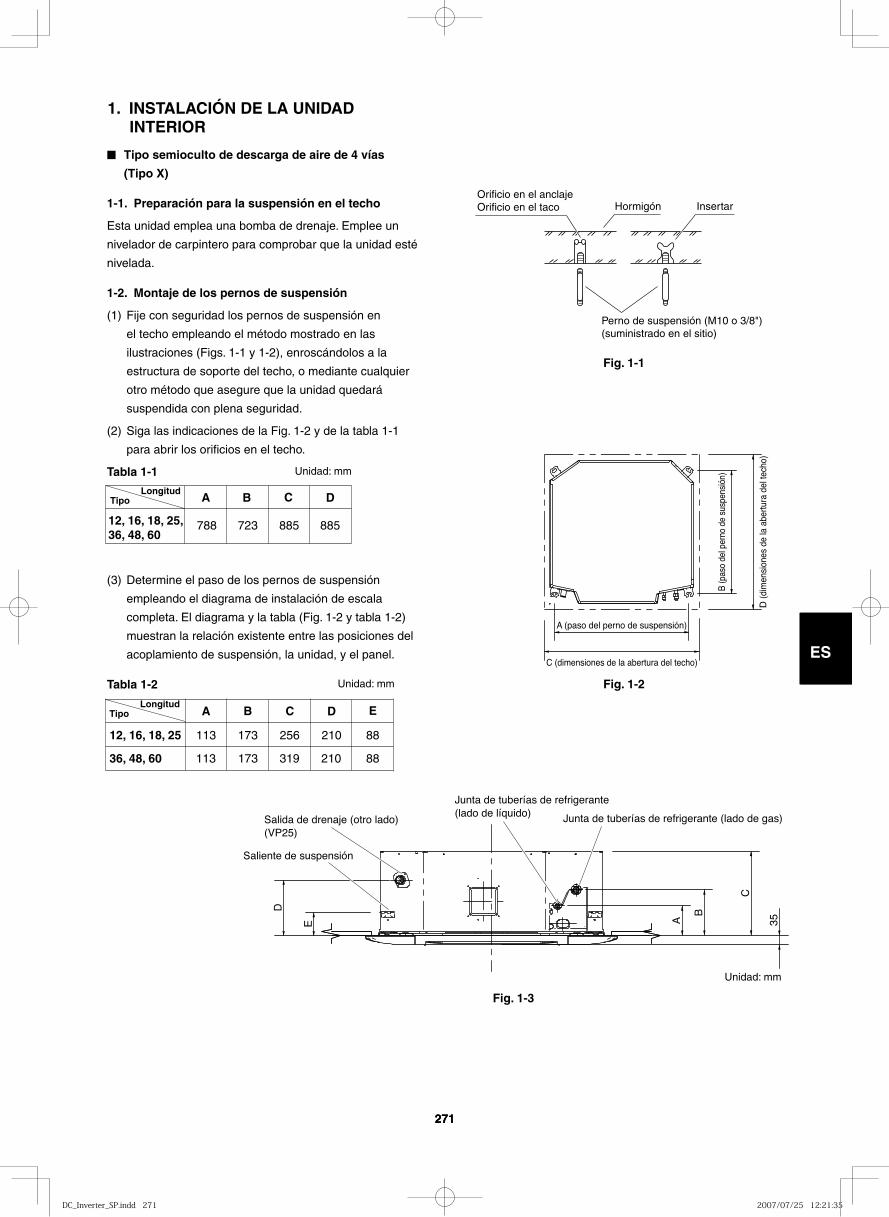
271
ES
271
ES
1. INSTALACIÓN DE LA UNIDAD INTERIOR
■ Tipo semioculto de descarga de aire de 4 vías
(Tipo X)
1-1. Preparación para la suspensión en el techo
Esta unidad emplea una bomba de drenaje. Emplee un
nivelador de carpintero para comprobar que la unidad esté
nivelada.
1-2. Montaje de los pernos de suspensión
(1) Fije con seguridad los pernos de suspensión en
el techo empleando el método mostrado en las
ilustraciones (Figs. 1-1 y 1-2), enroscándolos a la
estructura de soporte del techo, o mediante cualquier
otro método que asegure que la unidad quedará
suspendida con plena seguridad.
(2) Siga las indicaciones de la Fig. 1-2 y de la tabla 1-1
para abrir los orificios en el techo.
Tabla 1-1 Unidad: mm
(3) Determine el paso de los pernos de suspensión
empleando el diagrama de instalación de escala
completa. El diagrama y la tabla (Fig. 1-2 y tabla 1-2)
muestran la relación existente entre las posiciones del
acoplamiento de suspensión, la unidad, y el panel.
Tabla 1-2 Unidad: mm
Fig. 1-1
Fig. 1-2
Orificio en el anclajeOrificio en el taco Hormigón Insertar
Perno de suspensión (M10 o 3/8") (suministrado en el sitio)
Tipo A B C D
788 723 88588512, 16, 18, 25, 36, 48, 60
Longitud
A B C D
113 173
173
210
210
256
36, 48, 60
12, 16, 18, 25
E
88
88319113
TipoLongitud
D (d
imen
sion
es d
e la
abe
rtura
del
tech
o)
C (dimensiones de la abertura del techo)
A (paso del perno de suspensión)
B (p
aso
del p
erno
de
susp
ensi
ón)
E A
B
C
D
35
Salida de drenaje (otro lado)(VP25)
Junta de tuberías de refrigerante (lado de líquido) Junta de tuberías de refrigerante (lado de gas)
Saliente de suspensión
Fig. 1-3
Unidad: mm
DC_Inverter_SP.indd 271DC_Inverter_SP.indd 271 2007/07/25 12:21:352007/07/25 12:21:35
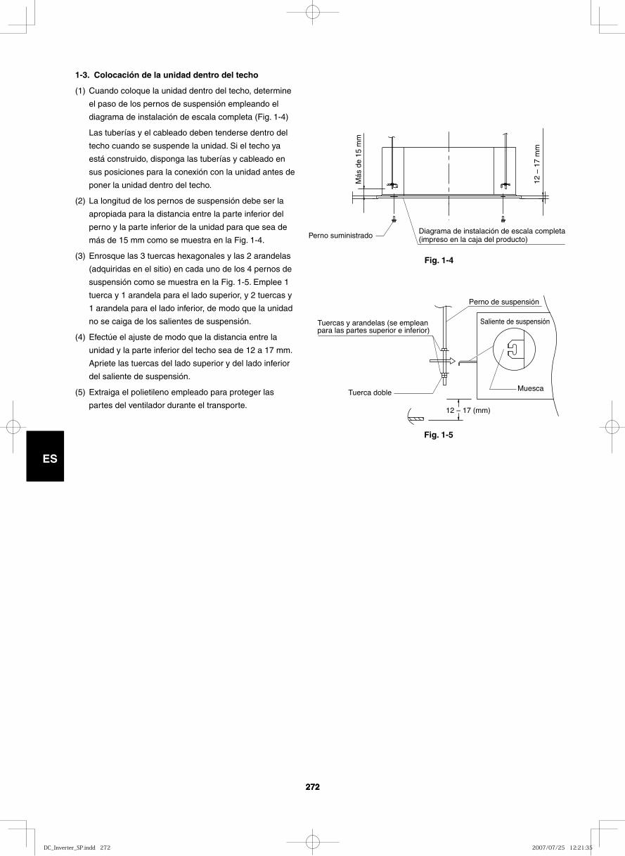
272
ES
272
ES
Fig. 1-4
Fig. 1-5
1-3. Colocación de la unidad dentro del techo
(1) Cuando coloque la unidad dentro del techo, determine
el paso de los pernos de suspensión empleando el
diagrama de instalación de escala completa (Fig. 1-4)
Las tuberías y el cableado deben tenderse dentro del
techo cuando se suspende la unidad. Si el techo ya
está construido, disponga las tuberías y cableado en
sus posiciones para la conexión con la unidad antes de
poner la unidad dentro del techo.
(2) La longitud de los pernos de suspensión debe ser la
apropiada para la distancia entre la parte inferior del
perno y la parte inferior de la unidad para que sea de
más de 15 mm como se muestra en la Fig. 1-4.
(3) Enrosque las 3 tuercas hexagonales y las 2 arandelas
(adquiridas en el sitio) en cada uno de los 4 pernos de
suspensión como se muestra en la Fig. 1-5. Emplee 1
tuerca y 1 arandela para el lado superior, y 2 tuercas y
1 arandela para el lado inferior, de modo que la unidad
no se caiga de los salientes de suspensión.
(4) Efectúe el ajuste de modo que la distancia entre la
unidad y la parte inferior del techo sea de 12 a 17 mm.
Apriete las tuercas del lado superior y del lado inferior
del saliente de suspensión.
(5) Extraiga el polietileno empleado para proteger las
partes del ventilador durante el transporte.
Diagrama de instalación de escala completa (impreso en la caja del producto)
12 –
17
mm
Más
de
15 m
m
Perno suministrado
12 – 17 (mm)
Tuercas y arandelas (se emplean para las partes superior e inferior)
Perno de suspensión
Saliente de suspensión
MuescaTuerca doble
DC_Inverter_SP.indd 272DC_Inverter_SP.indd 272 2007/07/25 12:21:352007/07/25 12:21:35
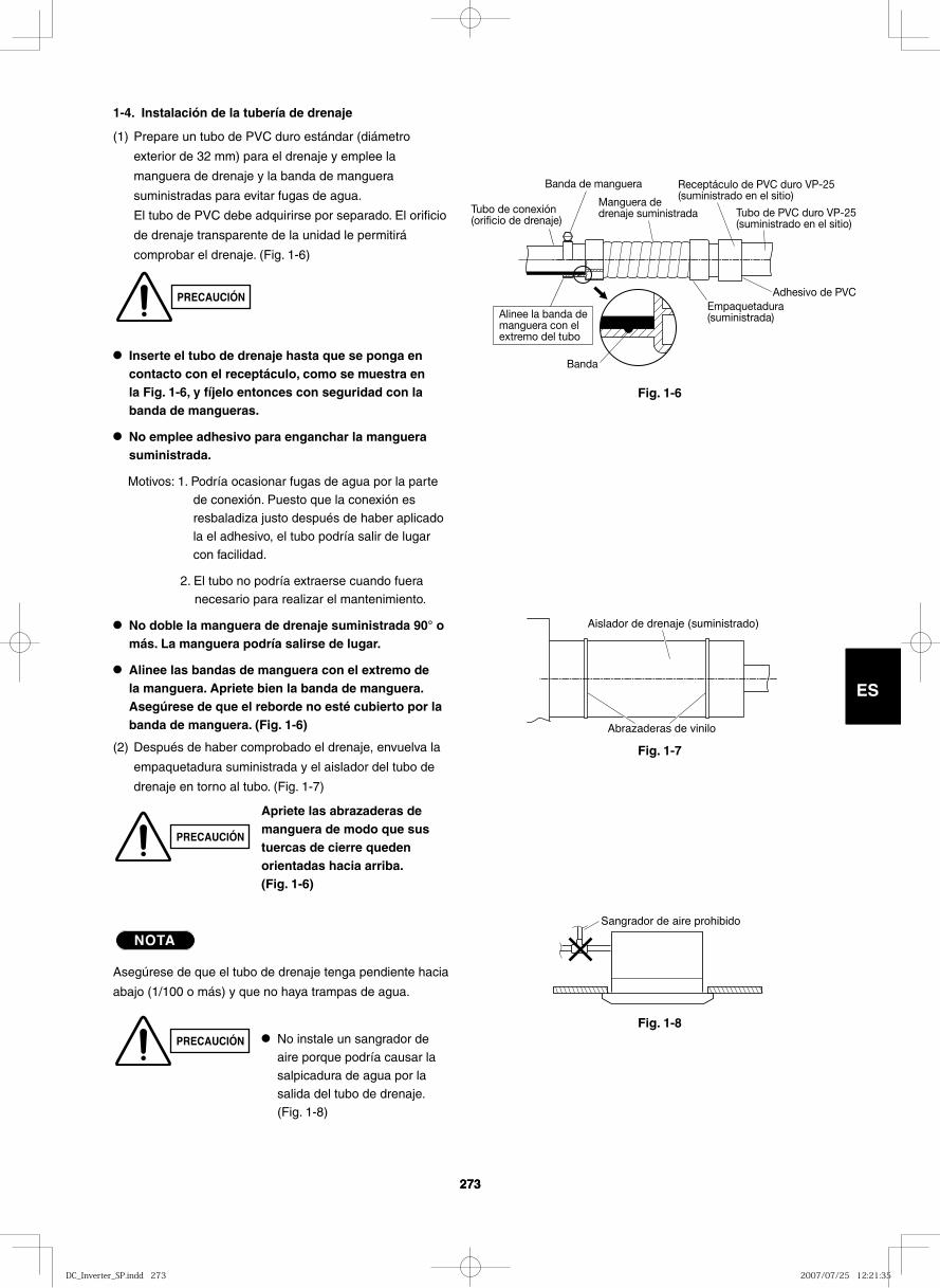
273
ES
273
ES
Receptáculo de PVC duro VP-25 (suministrado en el sitio)
Tubo de conexión (orificio de drenaje)
Banda de manguera
Manguera de drenaje suministrada Tubo de PVC duro VP-25
(suministrado en el sitio)
Adhesivo de PVCEmpaquetadura (suministrada)
Banda
Alinee la banda de manguera con el extremo del tubo
1-4. Instalación de la tubería de drenaje
(1) Prepare un tubo de PVC duro estándar (diámetro
exterior de 32 mm) para el drenaje y emplee la
manguera de drenaje y la banda de manguera
suministradas para evitar fugas de agua.
El tubo de PVC debe adquirirse por separado. El orificio
de drenaje transparente de la unidad le permitirá
comprobar el drenaje. (Fig. 1-6)
● Inserte el tubo de drenaje hasta que se ponga en contacto con el receptáculo, como se muestra en la Fig. 1-6, y fíjelo entonces con seguridad con la banda de mangueras.
● No emplee adhesivo para enganchar la manguera suministrada.
Motivos: 1. Podría ocasionar fugas de agua por la parte de conexión. Puesto que la conexión es resbaladiza justo después de haber aplicado la el adhesivo, el tubo podría salir de lugar con facilidad.
2. El tubo no podría extraerse cuando fuera necesario para realizar el mantenimiento.
● No doble la manguera de drenaje suministrada 90° o más. La manguera podría salirse de lugar.
● Alinee las bandas de manguera con el extremo de la manguera. Apriete bien la banda de manguera. Asegúrese de que el reborde no esté cubierto por la banda de manguera. (Fig. 1-6)
(2) Después de haber comprobado el drenaje, envuelva la
empaquetadura suministrada y el aislador del tubo de
drenaje en torno al tubo. (Fig. 1-7)
NOTA
Asegúrese de que el tubo de drenaje tenga pendiente hacia
abajo (1/100 o más) y que no haya trampas de agua.
Fig. 1-6
Fig. 1-7
Fig. 1-8
Aislador de drenaje (suministrado)
Abrazaderas de vinilo
Sangrador de aire prohibido
PRECAUCIÓN
PRECAUCIÓN
PRECAUCIÓN ● No instale un sangrador de aire porque podría causar la salpicadura de agua por la salida del tubo de drenaje. (Fig. 1-8)
Apriete las abrazaderas de manguera de modo que sus tuercas de cierre queden orientadas hacia arriba. (Fig. 1-6)
DC_Inverter_SP.indd 273DC_Inverter_SP.indd 273 2007/07/25 12:21:352007/07/25 12:21:35
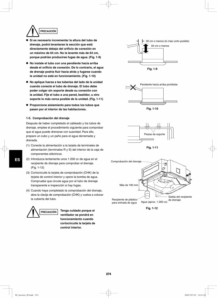
274
ES
274
ES
Fig. 1-9
30 cm o menos (lo más corto posible)
64 cm o menos
Fig. 1-10
Pendiente hacia arriba prohibida
Fig. 1-11
Piezas de soporte
Comprobación del drenaje
Salida del recipiente de drenaje
Agua (aprox. 1.200 cc)Recipiente de plástico para entrada de agua
Más de 100 mm
● Si es necesario incrementar la altura del tubo de drenaje, podrá levantarse la sección que está directamente debajo del orificio de conexión en un máximo de 64 cm. No la levante más de 64 cm, porque podrían producirse fugas de agua. (Fig. 1-9)
● No instale el tubo con una pendiente hacia arriba desde el orificio de conexión. De lo contrario, el agua de drenaje podría fluir hacia atrás y fugarse cuando la unidad no está en funcionamiento. (Fig. 1-10)
● No aplique fuerza a las tuberías del lado de la unidad cuando conecte el tubo de drenaje. El tubo debe poder colgar sin soporte desde su conexión con la unidad. Fije el tubo a una pared, bastidor, u otro soporte lo más cerca posible de la unidad. (Fig. 1-11)
● Proporcione aislamiento para todos los tubos que pasen por el interior de las habitaciones.
1-5. Comprobación del drenaje
Después de haber completado el cableado y los tubos de drenaje, emplee el procedimiento siguiente para comprobar que el agua puede drenarse con suavidad. Para ello, prepare un cubo y un paño para el agua derramada y drenada.
(1) Conecte la alimentación a la tarjeta de terminales de alimentación (terminales R y S) del interior de la caja de componentes eléctricos.
(2) Introduzca lentamente unos 1.200 cc de agua en el recipiente de drenaje para comprobar el drenaje. (Fig. 1-12)
(3) Cortocircuite la tarjeta de comprobación (CHK) de la tarjeta de control interior y opere la bomba de agua. Compruebe que circule agua por el tubo de drenaje transparente e inspección si hay fugas.
(4) Cuando haya completado la comprobación del drenaje,
abra la clavija de comprobación (CHK) y vuelva a colocar la cubierta del tubo.
Tenga cuidado porque el ventilador se pondrá en funcionamiento cuando cortocircuite la tarjeta de control interior.
PRECAUCIÓN
PRECAUCIÓNFig. 1-12
DC_Inverter_SP.indd 274DC_Inverter_SP.indd 274 2007/07/25 12:21:352007/07/25 12:21:35
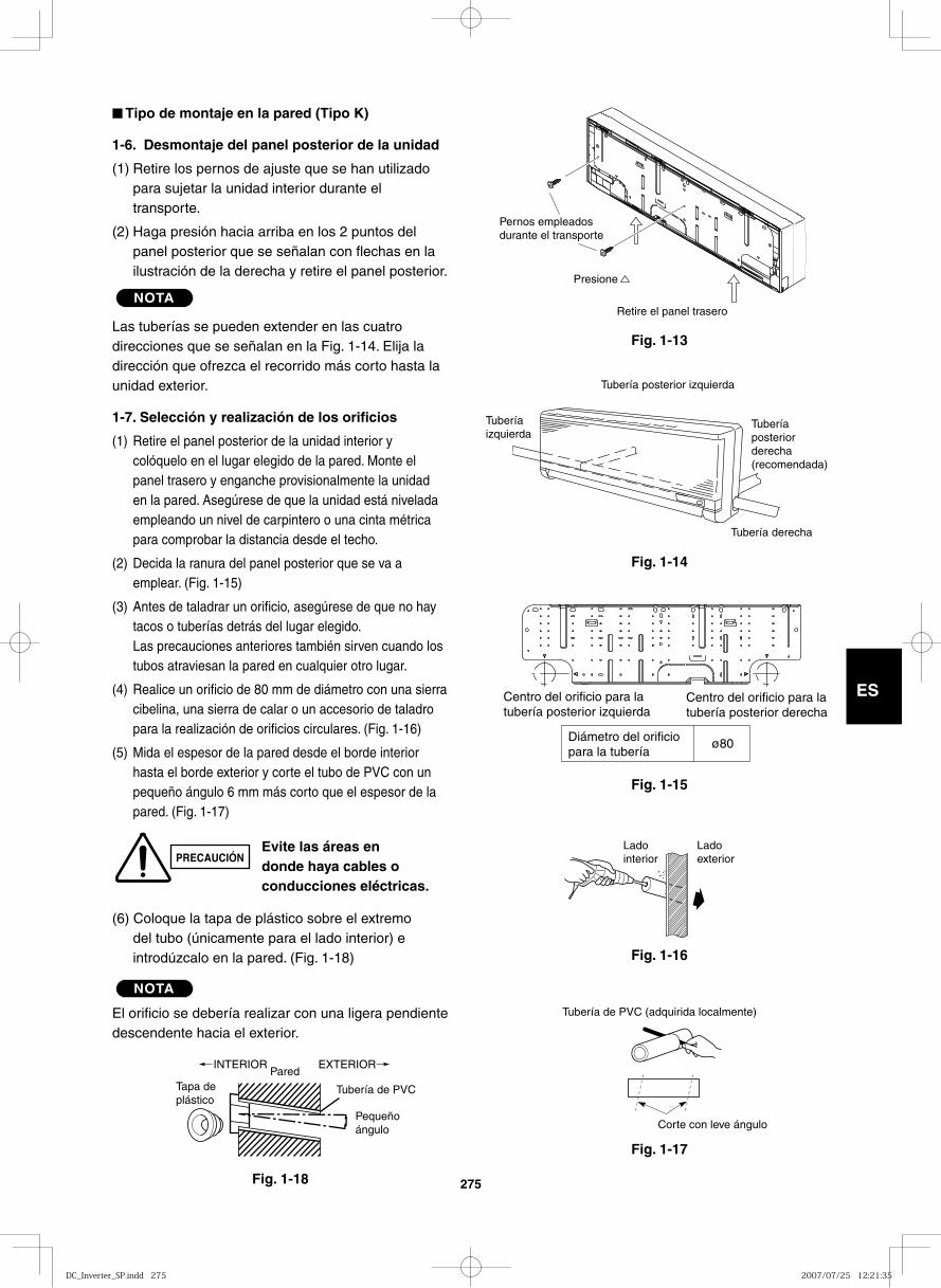
275
ES
■ Tipo de montaje en la pared (Tipo K)
1-6. Desmontaje del panel posterior de la unidad
(1) Retire los pernos de ajuste que se han utilizado para sujetar la unidad interior durante el transporte.
(2) Haga presión hacia arriba en los 2 puntos del panel posterior que se señalan con flechas en la ilustración de la derecha y retire el panel posterior.
NOTA
Las tuberías se pueden extender en las cuatro direcciones que se señalan en la Fig. 1-14. Elija la dirección que ofrezca el recorrido más corto hasta la unidad exterior.
1-7. Selección y realización de los orificios
(1) Retire el panel posterior de la unidad interior y colóquelo en el lugar elegido de la pared. Monte el panel trasero y enganche provisionalmente la unidad en la pared. Asegúrese de que la unidad está nivelada empleando un nivel de carpintero o una cinta métrica para comprobar la distancia desde el techo.
(2) Decida la ranura del panel posterior que se va a emplear. (Fig. 1-15)
(3) Antes de taladrar un orificio, asegúrese de que no hay tacos o tuberías detrás del lugar elegido.Las precauciones anteriores también sirven cuando los tubos atraviesan la pared en cualquier otro lugar.
(4) Realice un orificio de 80 mm de diámetro con una sierra cibelina, una sierra de calar o un accesorio de taladro para la realización de orificios circulares. (Fig. 1-16)
(5) Mida el espesor de la pared desde el borde interior hasta el borde exterior y corte el tubo de PVC con un pequeño ángulo 6 mm más corto que el espesor de la pared. (Fig. 1-17)
(6) Coloque la tapa de plástico sobre el extremo del tubo (únicamente para el lado interior) e introdúzcalo en la pared. (Fig. 1-18)
NOTA
El orificio se debería realizar con una ligera pendiente descendente hacia el exterior.
Fig. 1-13
Fig. 1-14
Fig. 1-15
Fig. 1-16
Fig. 1-17
Fig. 1-18
Tapa deplástico
INTERIORPared
Pequeño ángulo
Tubería de PVC
EXTERIOR
Corte con leve ángulo
Tubería de PVC (adquirida localmente)
Ladointerior
Ladoexterior
Centro del orificio para la tubería posterior izquierda
Centro del orificio para la tubería posterior derecha
Diámetro del orificio para la tubería
ø80
Tubería izquierda
Tubería posterior derecha(recomendada)
Tubería derecha
Tubería posterior izquierda
Retire el panel trasero
Presione
Pernos empleados durante el transporte
PRECAUCIÓNEvite las áreas en donde haya cables o conducciones eléctricas.
DC_Inverter_SP.indd 275DC_Inverter_SP.indd 275 2007/07/25 12:21:352007/07/25 12:21:35
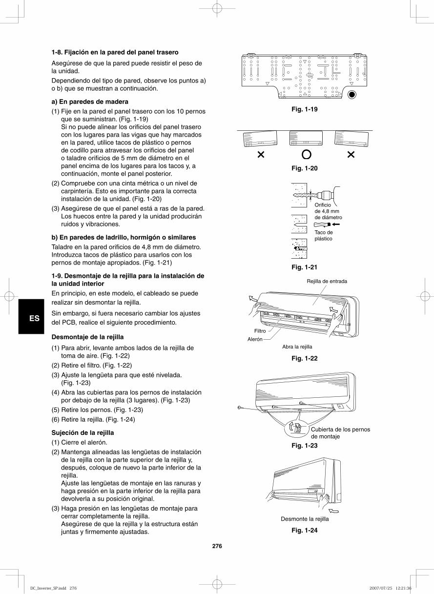
276
ES
Fig. 1-19
Fig. 1-20
Fig. 1-21
Fig. 1-22
Fig. 1-23
Fig. 1-24
Orificio de 4,8 mm de diámetro
Taco de plástico
Rejilla de entrada
Filtro
Alerón
Abra la rejilla
Cubierta de los pernos de montaje
Desmonte la rejilla
1-8. Fijación en la pared del panel trasero
Asegúrese de que la pared puede resistir el peso de la unidad.
Dependiendo del tipo de pared, observe los puntos a) o b) que se muestran a continuación.
a) En paredes de madera(1) Fije en la pared el panel trasero con los 10 pernos
que se suministran. (Fig. 1-19)Si no puede alinear los orificios del panel trasero con los lugares para las vigas que hay marcados en la pared, utilice tacos de plástico o pernos de codillo para atravesar los orificios del panel o taladre orificios de 5 mm de diámetro en el panel encima de los lugares para los tacos y, a continuación, monte el panel posterior.
(2) Compruebe con una cinta métrica o un nivel de carpintería. Esto es importante para la correcta instalación de la unidad. (Fig. 1-20)
(3) Asegúrese de que el panel está a ras de la pared. Los huecos entre la pared y la unidad producirán ruidos y vibraciones.
b) En paredes de ladrillo, hormigón o similaresTaladre en la pared orificios de 4,8 mm de diámetro. Introduzca tacos de plástico para usarlos con los pernos de montaje apropiados. (Fig. 1-21)
1-9. Desmontaje de la rejilla para la instalación de la unidad interiorEn principio, en este modelo, el cableado se puede realizar sin desmontar la rejilla.
Sin embargo, si fuera necesario cambiar los ajustes del PCB, realice el siguiente procedimiento.
Desmontaje de la rejilla
(1) Para abrir, levante ambos lados de la rejilla de toma de aire. (Fig. 1-22)
(2) Retire el filtro. (Fig. 1-22)
(3) Ajuste la lengüeta para que esté nivelada. (Fig. 1-23)
(4) Abra las cubiertas para los pernos de instalación por debajo de la rejilla (3 lugares). (Fig. 1-23)
(5) Retire los pernos. (Fig. 1-23)
(6) Retire la rejilla. (Fig. 1-24)
Sujeción de la rejilla(1) Cierre el alerón.
(2) Mantenga alineadas las lengüetas de instalación de la rejilla con la parte superior de la rejilla y, después, coloque de nuevo la parte inferior de la rejilla. Ajuste las lengüetas de montaje en las ranuras y haga presión en la parte inferior de la rejilla para devolverla a su posición original.
(3) Haga presión en las lengüetas de montaje para cerrar completamente la rejilla. Asegúrese de que la rejilla y la estructura están juntas y firmemente ajustadas.
DC_Inverter_SP.indd 276DC_Inverter_SP.indd 276 2007/07/25 12:21:362007/07/25 12:21:36
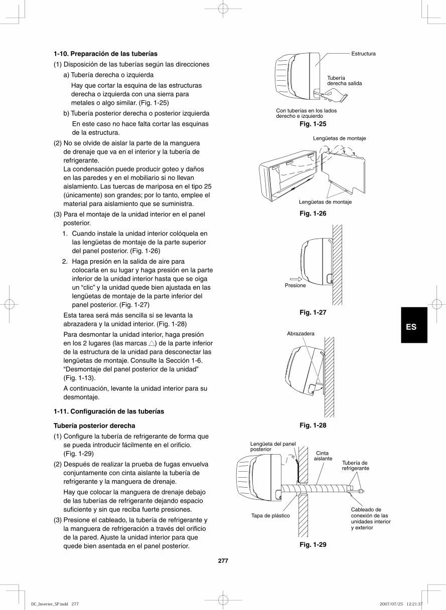
277
ES
1-10. Preparación de las tuberías
(1) Disposición de las tuberías según las direcciones
a) Tubería derecha o izquierda
Hay que cortar la esquina de las estructuras derecha o izquierda con una sierra para metales o algo similar. (Fig. 1-25)
b) Tubería posterior derecha o posterior izquierda
En este caso no hace falta cortar las esquinas de la estructura.
(2) No se olvide de aislar la parte de la manguera de drenaje que va en el interior y la tubería de refrigerante. La condensación puede producir goteo y daños en las paredes y en el mobiliario si no llevan aislamiento. Las tuercas de mariposa en el tipo 25 (únicamente) son grandes; por lo tanto, emplee el material para aislamiento que se suministra.
(3) Para el montaje de la unidad interior en el panel posterior.
1. Cuando instale la unidad interior colóquela en las lengüetas de montaje de la parte superior del panel posterior. (Fig. 1-26)
2. Haga presión en la salida de aire para colocarla en su lugar y haga presión en la parte inferior de la unidad interior hasta que se oiga un “clic” y la unidad quede bien ajustada en las lengüetas de montaje de la parte inferior del panel posterior. (Fig. 1-27)
Esta tarea será más sencilla si se levanta la abrazadera y la unidad interior. (Fig. 1-28)
Para desmontar la unidad interior, haga presión en los 2 lugares (las marcas ▲▲) de la parte inferior de la estructura de la unidad para desconectar las lengüetas de montaje. Consulte la Sección 1-6. “Desmontaje del panel posterior de la unidad” (Fig. 1-13).
A continuación, levante la unidad interior para su desmontaje.
1-11. Configuración de las tuberías
Tubería posterior derecha
(1) Configure la tubería de refrigerante de forma que se pueda introducir fácilmente en el orificio. (Fig. 1-29)
(2) Después de realizar la prueba de fugas envuelva conjuntamente con cinta aislante la tubería de refrigerante y la manguera de drenaje.
Hay que colocar la manguera de drenaje debajo de las tuberías de refrigerante dejando espacio suficiente y sin que reciba fuerte presiones.
(3) Presione el cableado, la tubería de refrigerante y la manguera de refrigeración a través del orificio de la pared. Ajuste la unidad interior para que quede bien asentada en el panel posterior.
Fig. 1-25
Estructura
Tubería derecha salida
Con tuberías en los lados derecho e izquierdo
Fig. 1-26
Lengüetas de montaje
Lengüetas de montaje
Fig. 1-27
Presione
Fig. 1-28
Abrazadera
Fig. 1-29
Cintaaislante
Tubería de refrigerante
Lengüeta del panel posterior
Tapa de plásticoCableado de conexión de las unidades interior y exterior
DC_Inverter_SP.indd 277DC_Inverter_SP.indd 277 2007/07/25 12:21:372007/07/25 12:21:37
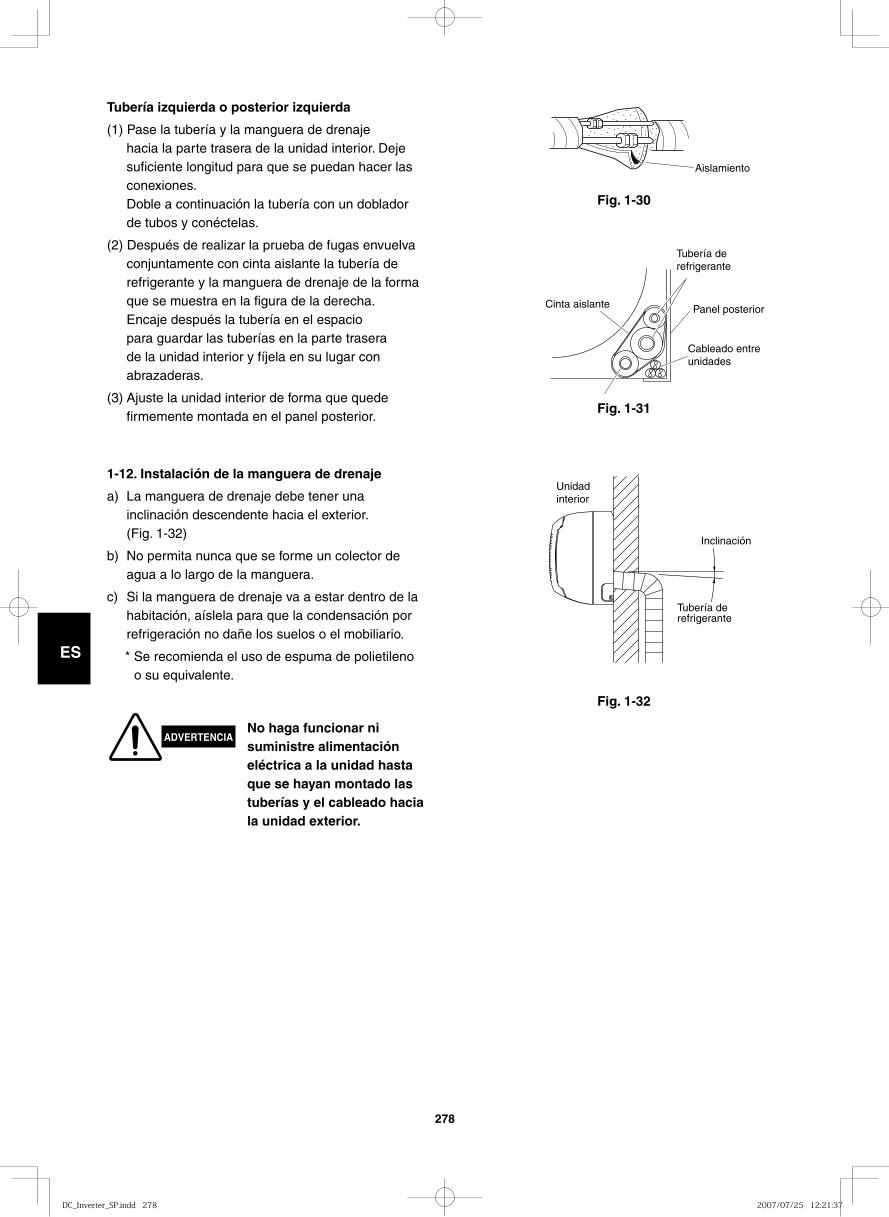
278
ES
Fig. 1-32
Fig. 1-30
Aislamiento
Fig. 1-31
Cinta aislante Panel posterior
Cableado entre unidades
Tubería de refrigerante
Unidadinterior
Inclinación
Tubería de refrigerante
1-12. Instalación de la manguera de drenaje
a) La manguera de drenaje debe tener una inclinación descendente hacia el exterior. (Fig. 1-32)
b) No permita nunca que se forme un colector de agua a lo largo de la manguera.
c) Si la manguera de drenaje va a estar dentro de la habitación, aíslela para que la condensación por refrigeración no dañe los suelos o el mobiliario.
* Se recomienda el uso de espuma de polietileno o su equivalente.
ADVERTENCIANo haga funcionar ni suministre alimentación eléctrica a la unidad hasta que se hayan montado las tuberías y el cableado hacia la unidad exterior.
Tubería izquierda o posterior izquierda
(1) Pase la tubería y la manguera de drenaje hacia la parte trasera de la unidad interior. Deje suficiente longitud para que se puedan hacer las conexiones.Doble a continuación la tubería con un doblador de tubos y conéctelas.
(2) Después de realizar la prueba de fugas envuelva conjuntamente con cinta aislante la tubería de refrigerante y la manguera de drenaje de la forma que se muestra en la figura de la derecha.Encaje después la tubería en el espacio para guardar las tuberías en la parte trasera de la unidad interior y fíjela en su lugar con abrazaderas.
(3) Ajuste la unidad interior de forma que quede firmemente montada en el panel posterior.
DC_Inverter_SP.indd 278DC_Inverter_SP.indd 278 2007/07/25 12:21:372007/07/25 12:21:37
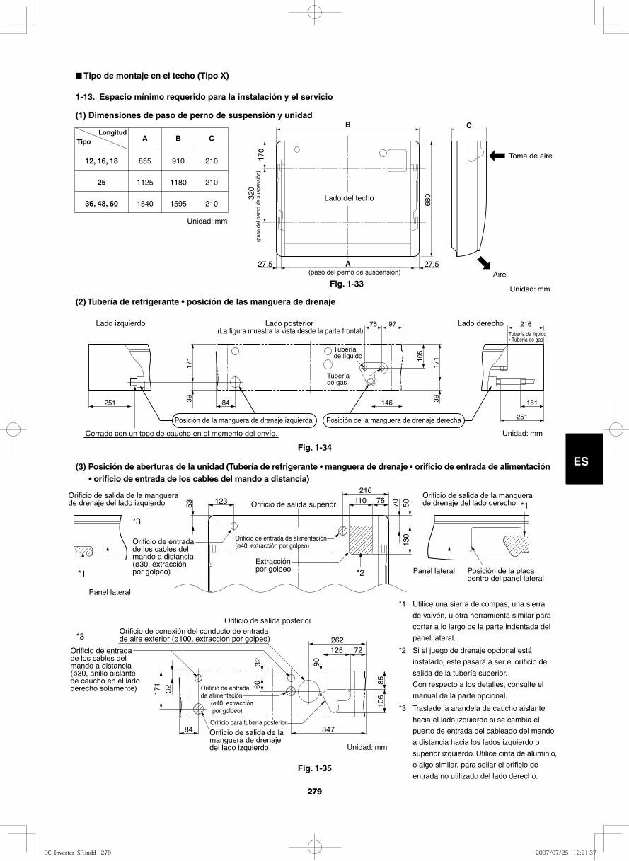
279
ES
279
ES
12, 16, 18
25
36, 48, 60
855
1125
1540
910
1180
1595
210
210
210
A B CTipoLongitud
B
A
C
170
320
680
27,5 27,5
Lado del techo
(paso del perno de suspensión)
(pas
o de
l per
no d
e su
spen
sión
)
Toma de aire
Aire
(2) Tubería de refrigerante • posición de las manguera de drenaje
251 84 146 161
75 97 216
39 39
171 10
5
171
251
Lado derechoLado izquierdo Lado posterior (La figura muestra la vista desde la parte frontal)
Posición de la manguera de drenaje izquierda Posición de la manguera de drenaje derecha
Cerrado con un tope de caucho en el momento del envío.
Tubería de gas
Tubería de líquido
Tubería de líquido• Tubería de gas
53 70123 110 76216
5013
0
Panel lateral
Panel lateral
Orificio de salida de la manguera de drenaje del lado izquierdo
Orificio de salida de la manguera de drenaje del lado izquierdo
Orificio de salida superior
84
32
3260
171
347
125 72
8510
6
90
262*3
*1
*1
*2
*3
Orificio de salida de la manguera de drenaje del lado derecho
Posición de la placa dentro del panel lateral
Orificio de salida posteriorOrificio de conexión del conducto de entrada de aire exterior (ø100, extracción por golpeo)
Orificio de entrada de los cables del mando a distancia (ø30, extracción por golpeo)
Orificio de entrada de los cables del mando a distancia (ø30, anillo aislante de caucho en el lado derecho solamente)
Orificio de entrada de alimentación (ø40, extracción por golpeo)
Orificio de entrada de alimentación (ø40, extracción por golpeo)
Extracción por golpeo
Orificio para tubería posterior
Fig. 1-33
Fig. 1-34
*1 Utilice una sierra de compás, una sierra
de vaivén, u otra herramienta similar para
cortar a lo largo de la parte indentada del
panel lateral.
*2 Si el juego de drenaje opcional está
instalado, éste pasará a ser el orificio de
salida de la tubería superior.
Con respecto a los detalles, consulte el
manual de la parte opcional.
*3 Traslade la arandela de caucho aislante
hacia el lado izquierdo si se cambia el
puerto de entrada del cableado del mando
a distancia hacia los lados izquierdo o
superior izquierdo. Utilice cinta de aluminio,
o algo similar, para sellar el orificio de
entrada no utilizado del lado derecho.
Unidad: mm
■ Tipo de montaje en el techo (Tipo X)
1-13. Espacio mínimo requerido para la instalación y el servicio
(1) Dimensiones de paso de perno de suspensión y unidad
(3) Posición de aberturas de la unidad (Tubería de refrigerante • manguera de drenaje • orificio de entrada de alimentación • orificio de entrada de los cables del mando a distancia)
Fig. 1-35
Unidad: mm
Unidad: mm
Unidad: mm
DC_Inverter_SP.indd 279DC_Inverter_SP.indd 279 2007/07/25 12:21:372007/07/25 12:21:37
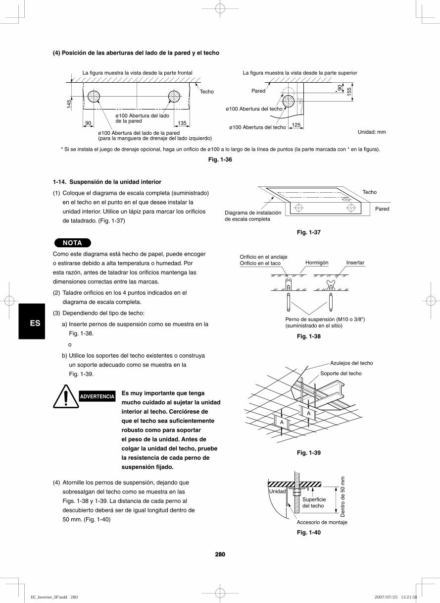
280
ES
280
ES
(4) Posición de las aberturas del lado de la pared y el techo
90
145
135 125
15590
ø100 Abertura del lado de la pared
ø100 Abertura del lado de la pared(para la manguera de drenaje del lado izquierdo)
ø100 Abertura del techo
ø100 Abertura del techo
La figura muestra la vista desde la parte frontal La figura muestra la vista desde la parte superior
Techo Pared *
Diagrama de instalación de escala completa
Techo
Pared
Fig. 1-37
Fig. 1-36
Fig. 1-38
1-14. Suspensión de la unidad interior
(1) Coloque el diagrama de escala completa (suministrado)
en el techo en el punto en el que desee instalar la
unidad interior. Utilice un lápiz para marcar los orificios
de taladrado. (Fig. 1-37)
NOTA
Como este diagrama está hecho de papel, puede encoger
o estirarse debido a alta temperatura o humedad. Por
esta razón, antes de taladrar los orificios mantenga las
dimensiones correctas entre las marcas.
(2) Taladre orificios en los 4 puntos indicados en el
diagrama de escala completa.
(3) Dependiendo del tipo de techo:
a) Inserte pernos de suspensión como se muestra en la
Fig. 1-38.
o
b) Utilice los soportes del techo existentes o construya
un soporte adecuado como se muestra en la
Fig. 1-39.
(4) Atornille los pernos de suspensión, dejando que
sobresalgan del techo como se muestra en las
Figs. 1-38 y 1-39. La distancia de cada perno al
descubierto deberá ser de igual longitud dentro de
50 mm. (Fig. 1-40)
Hormigón Insertar
Perno de suspensión (M10 o 3/8") (suministrado en el sitio)
Orificio en el anclajeOrificio en el taco
Fig. 1-39
Fig. 1-40
A
A
Soporte del techo
Azulejos del techo
Superficie del techo
Den
tro
de 5
0 m
m
Accesorio de montaje
Unidad
ADVERTENCIAEs muy importante que tenga
mucho cuidado al sujetar la unidad
interior al techo. Cerciórese de
que el techo sea suficientemente
robusto como para soportar
el peso de la unidad. Antes de
colgar la unidad del techo, pruebe
la resistencia de cada perno de
suspensión fijado.
* Si se instala el juego de drenaje opcional, haga un orificio de ø100 a lo largo de la línea de puntos (la parte marcada con * en la figura).
Unidad: mm
DC_Inverter_SP.indd 280DC_Inverter_SP.indd 280 2007/07/25 12:21:382007/07/25 12:21:38
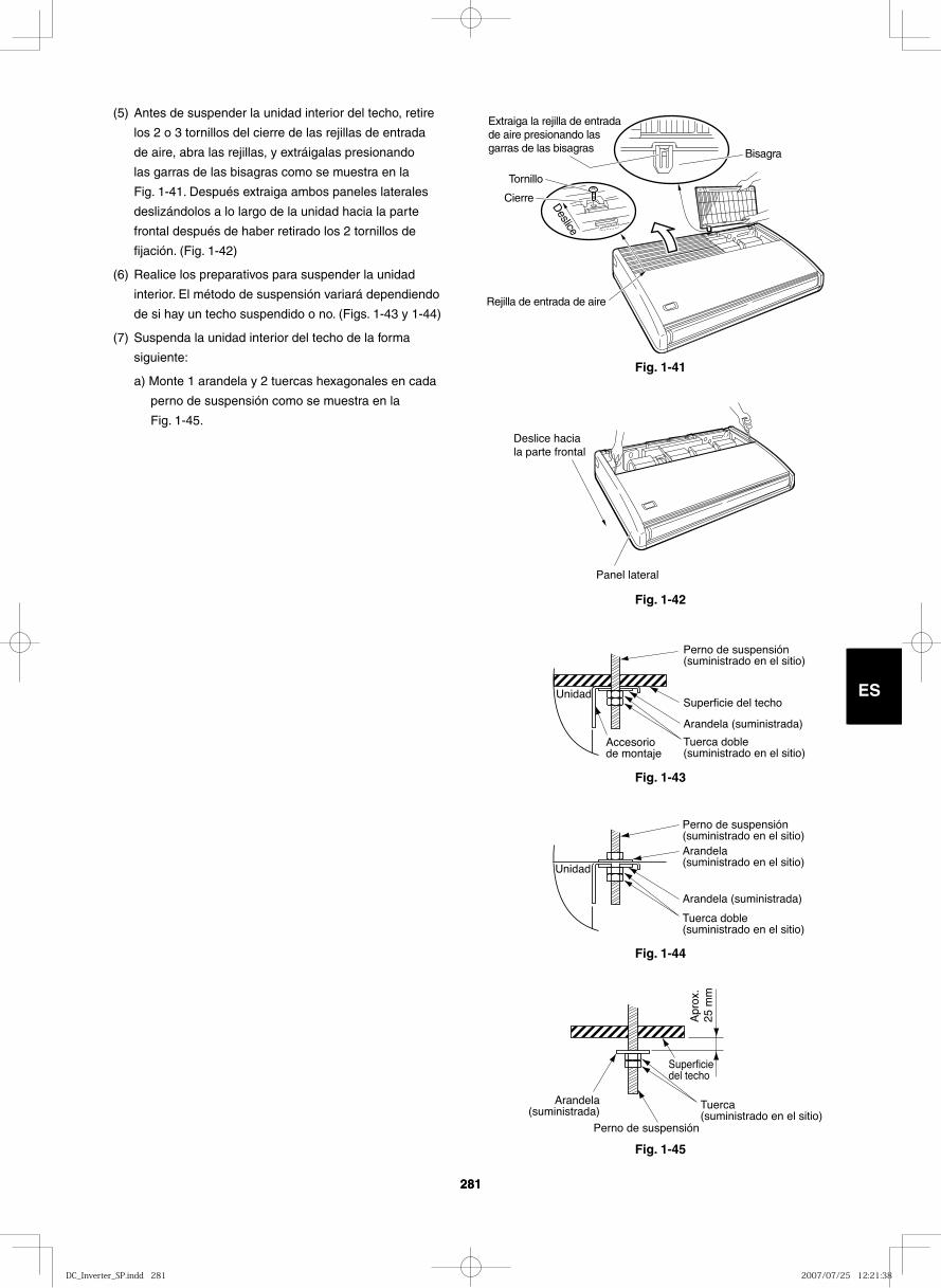
281
ES
281
ES
Fig. 1-41D
eslice
Cierre
Tornillo
Extraiga la rejilla de entrada de aire presionando las garras de las bisagras Bisagra
Rejilla de entrada de aire
Fig. 1-42
Deslice hacia la parte frontal
Panel lateral
Fig. 1-43
Unidad
Perno de suspensión (suministrado en el sitio)
Accesorio de montaje
Superficie del techo
Arandela (suministrada)
Tuerca doble (suministrado en el sitio)
Fig. 1-44
Unidad
Perno de suspensión (suministrado en el sitio)
Arandela (suministrada)
Arandela (suministrado en el sitio)
Tuerca doble(suministrado en el sitio)
Fig. 1-45
Tuerca (suministrado en el sitio)
Perno de suspensión
Superficie del techo
Arandela(suministrada)
Apr
ox.
25 m
m
(5) Antes de suspender la unidad interior del techo, retire
los 2 o 3 tornillos del cierre de las rejillas de entrada
de aire, abra las rejillas, y extráigalas presionando
las garras de las bisagras como se muestra en la
Fig. 1-41. Después extraiga ambos paneles laterales
deslizándolos a lo largo de la unidad hacia la parte
frontal después de haber retirado los 2 tornillos de
fijación. (Fig. 1-42)
(6) Realice los preparativos para suspender la unidad
interior. El método de suspensión variará dependiendo
de si hay un techo suspendido o no. (Figs. 1-43 y 1-44)
(7) Suspenda la unidad interior del techo de la forma
siguiente:
a) Monte 1 arandela y 2 tuercas hexagonales en cada
perno de suspensión como se muestra en la
Fig. 1-45.
DC_Inverter_SP.indd 281DC_Inverter_SP.indd 281 2007/07/25 12:21:382007/07/25 12:21:38
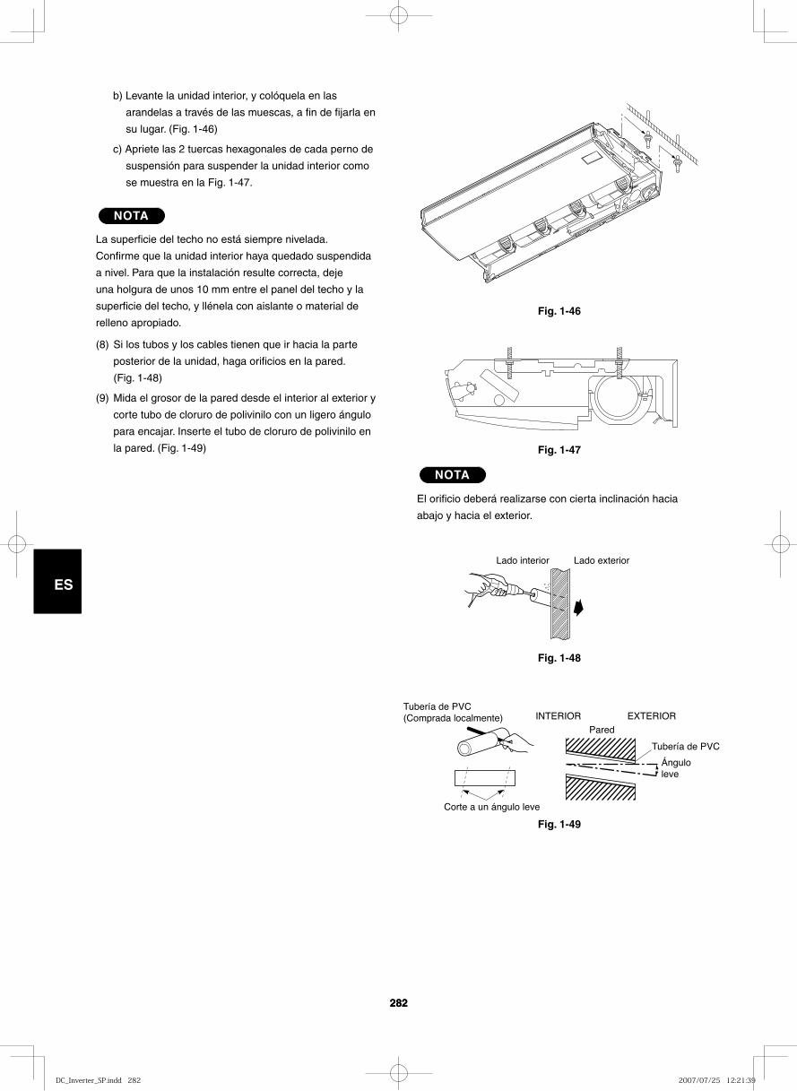
282
ES
282
ES
Fig. 1-46
Fig. 1-47
Fig. 1-48
Lado interior Lado exterior
Fig. 1-49
Tubería de PVC (Comprada localmente)
Corte a un ángulo leve
INTERIOR EXTERIORPared
Ángulo leve
Tubería de PVC
b) Levante la unidad interior, y colóquela en las
arandelas a través de las muescas, a fin de fijarla en
su lugar. (Fig. 1-46)
c) Apriete las 2 tuercas hexagonales de cada perno de
suspensión para suspender la unidad interior como
se muestra en la Fig. 1-47.
NOTA
La superficie del techo no está siempre nivelada.
Confirme que la unidad interior haya quedado suspendida
a nivel. Para que la instalación resulte correcta, deje
una holgura de unos 10 mm entre el panel del techo y la
superficie del techo, y llénela con aislante o material de
relleno apropiado.
(8) Si los tubos y los cables tienen que ir hacia la parte
posterior de la unidad, haga orificios en la pared.
(Fig. 1-48)
(9) Mida el grosor de la pared desde el interior al exterior y
corte tubo de cloruro de polivinilo con un ligero ángulo
para encajar. Inserte el tubo de cloruro de polivinilo en
la pared. (Fig. 1-49)
NOTA
El orificio deberá realizarse con cierta inclinación hacia
abajo y hacia el exterior.
DC_Inverter_SP.indd 282DC_Inverter_SP.indd 282 2007/07/25 12:21:392007/07/25 12:21:39
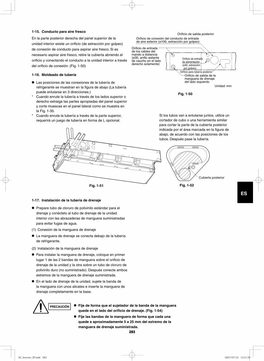
283
ES ES
Orificio de salida de la manguera de drenaje del lado izquierdo
Orificio de salida posteriorOrificio de conexión del conducto de entrada de aire exterior (ø100, extracción por golpeo)
Orificio de entrada de los cables del mando a distancia (ø30, anillo aislante de caucho en el lado derecho solamente)
Orificio de entrada de alimentación (ø40, extracción por golpeo)
Orificio para tubería posterior
1-15. Conducto para aire fresco
En la parte posterior derecha del panel superior de la
unidad interior existe un orificio (de extracción por golpeo)
de conexión de conducto para aspirar aire fresco. Si es
necesario aspirar aire fresco, retire la cubierta abriendo el
orificio y conectando el conducto a la unidad interior a través
del orificio de conexión. (Fig. 1-50)
1-16. Moldeado de tubería
● Las posiciones de las conexiones de la tubería de refrigerante se muestran en la figura de abajo (La tubería puede enlutarse en 3 direcciones.)
* Cuando enrute la tubería a través de los lados superior o derecho extraiga las partes apropiadas del panel superior y corte muescas en el panel lateral como se muestra en la Fig. 1-35.
* Cuando enrute la tubería a través de la parte superior, requerirá un juego de tubería en forma de L opcional.
1-17. Instalación de la tubería de drenaje
● Prepare tubo de cloruro de polivinilo estándar para el drenaje y conéctelo al tubo de drenaje de la unidad interior con las abrazaderas de manguera suministradas para evitar fugas de agua.
(1) Conexión de la manguera de drenaje
● La manguera de drenaje se conecta debajo de la tubería de refrigerante.
(2) Instalación de la manguera de drenaje
● Para instalar la manguera de drenaje, coloque en primer lugar 1 de las 2 bandas de manguera sobre el orificio de drenaje de la unidad y la otra sobre un tubo de cloruro de polivinilo duro (no suministrado). Después conecte ambos extremos de la manguera de drenaje suministrada.
● En el lado de drenaje de la unidad, sujete la banda de la manguera con unos alicates e inserte la manguera de drenaje completamente en la base.
Fig. 1-50
Cubierta posterior
● Fije de forma que el sujetador de la banda de la manguera quede en el lado del orificio de drenaje. (Fig. 1-54)
● Fije las bandas de la manguera de forma que cada una quede a aproximadamente 5 a 25 mm del extremo de la manguera de drenaje suministrada.
Si los tubos van a enlutarse juntos, utilice un cortador de cubo o una herramienta similar para cortar la parte de la cubierta posterior indicada por el área marcada en la figura de abajo, de acuerdo con las posiciones de los tubos. Después pase la tubería.
Fig. 1-51 Fig. 1-52
PRECAUCIÓN
283
Unidad: mm
DC_Inverter_SP.indd 283DC_Inverter_SP.indd 283 2007/07/25 12:21:392007/07/25 12:21:39
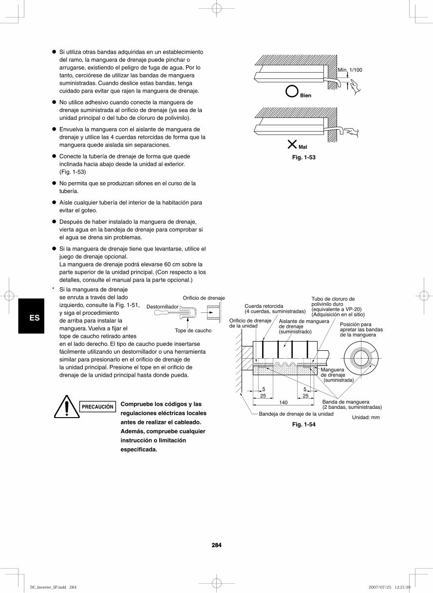
284
ES
284
ES
14025 25
55
Orificio de drenaje de la unidad
Cuerda retorcida (4 cuerdas, suministradas)
Aislante de manguera de drenaje (suministrado)
Posición para apretar las bandas de la manguera
Manguera de drenaje (suministrada)
Banda de manguera (2 bandas, suministradas)
Bandeja de drenaje de la unidad
Tubo de cloruro de polivinilo duro (equivalente a VP-20) (Adquisición en el sitio)
Bien
Mín. 1/100
Mal
Fig. 1-53
● Si utiliza otras bandas adquiridas en un establecimiento del ramo, la manguera de drenaje puede pinchar o arrugarse, existiendo el peligro de fuga de agua. Por lo tanto, cerciórese de utilizar las bandas de manguera suministradas. Cuando deslice estas bandas, tenga cuidado para evitar que rajen la manguera de drenaje.
● No utilice adhesivo cuando conecte la manguera de drenaje suministrada al orificio de drenaje (ya sea de la unidad principal o del tubo de cloruro de polivinilo).
● Envuelva la manguera con el aislante de manguera de drenaje y utilice las 4 cuerdas retorcidas de forma que la manguera quede aislada sin separaciones.
● Conecte la tubería de drenaje de forma que quede inclinada hacia abajo desde la unidad al exterior. (Fig. 1-53)
● No permita que se produzcan sifones en el curso de la tubería.
● Aísle cualquier tubería del interior de la habitación para evitar el goteo.
● Después de haber instalado la manguera de drenaje, vierta agua en la bandeja de drenaje para comprobar si el agua se drena sin problemas.
● Si la manguera de drenaje tiene que levantarse, utilice el juego de drenaje opcional. La manguera de drenaje podrá elevarse 60 cm sobre la parte superior de la unidad principal. (Con respecto a los detalles, consulte el manual para la parte opcional.)
* Si la manguera de drenaje se enruta a través del lado izquierdo, consulte la Fig. 1-51, y siga el procedimiento de arriba para instalar la manguera. Vuelva a fijar el tope de caucho retirado antes en el lado derecho. El tipo de caucho puede insertarse fácilmente utilizando un destornillador o una herramienta similar para presionarlo en el orificio de drenaje de la unidad principal. Presione el tope en el orificio de drenaje de la unidad principal hasta donde pueda.
Destornillador
Orificio de drenaje
Tope de caucho
Compruebe los códigos y las
regulaciones eléctricas locales
antes de realizar el cableado.
Además, compruebe cualquier
instrucción o limitación
especificada.
PRECAUCIÓN
Fig. 1-54Unidad: mm
DC_Inverter_SP.indd 284DC_Inverter_SP.indd 284 2007/07/25 12:21:392007/07/25 12:21:39
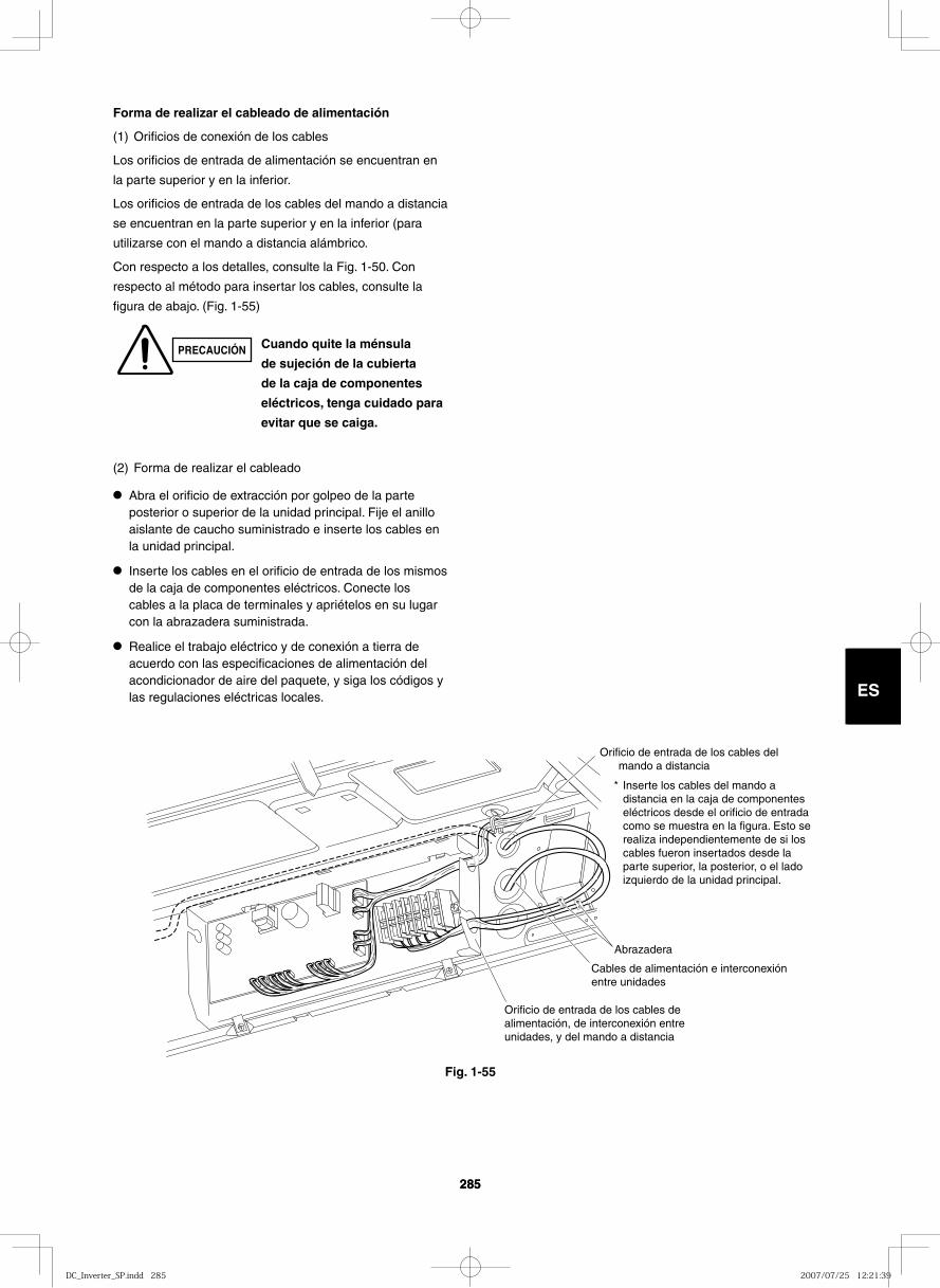
285
ES
285
ES
Orificio de entrada de los cables del mando a distancia
Abrazadera
Cables de alimentación e interconexión entre unidades
Orificio de entrada de los cables de alimentación, de interconexión entre unidades, y del mando a distancia
Inserte los cables del mando a distancia en la caja de componentes eléctricos desde el orificio de entrada como se muestra en la figura. Esto se realiza independientemente de si los cables fueron insertados desde la parte superior, la posterior, o el lado izquierdo de la unidad principal.
*
Forma de realizar el cableado de alimentación
(1) Orificios de conexión de los cables
Los orificios de entrada de alimentación se encuentran en
la parte superior y en la inferior.
Los orificios de entrada de los cables del mando a distancia
se encuentran en la parte superior y en la inferior (para
utilizarse con el mando a distancia alámbrico.
Con respecto a los detalles, consulte la Fig. 1-50. Con
respecto al método para insertar los cables, consulte la
figura de abajo. (Fig. 1-55)
(2) Forma de realizar el cableado
● Abra el orificio de extracción por golpeo de la parte posterior o superior de la unidad principal. Fije el anillo aislante de caucho suministrado e inserte los cables en la unidad principal.
● Inserte los cables en el orificio de entrada de los mismos de la caja de componentes eléctricos. Conecte los cables a la placa de terminales y apriételos en su lugar con la abrazadera suministrada.
● Realice el trabajo eléctrico y de conexión a tierra de acuerdo con las especificaciones de alimentación del acondicionador de aire del paquete, y siga los códigos y las regulaciones eléctricas locales.
Fig. 1-55
PRECAUCIÓN Cuando quite la ménsula
de sujeción de la cubierta
de la caja de componentes
eléctricos, tenga cuidado para
evitar que se caiga.
DC_Inverter_SP.indd 285DC_Inverter_SP.indd 285 2007/07/25 12:21:392007/07/25 12:21:39
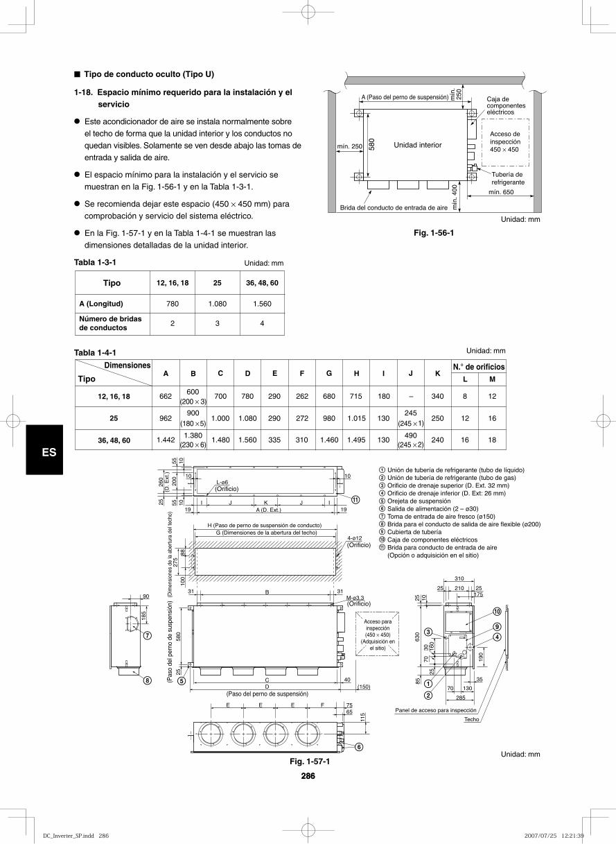
286
ES
286
ES
Fig. 1-56-1
Fig. 1-57-1
Unidad interior
Acceso de inspección 450 × 45058
0
A (Paso del perno de suspensión) Caja de componentes eléctricos
Tubería de refrigerante
Brida del conducto de entrada de aire
mín. 250
mín. 650
mín
.25
0m
ín. 4
00
9
10
9
10
11
11
M-ø3,3
4-ø12
(Orificio)
A (D. Ext.)
L-ø6
I
10 10
105555
200
10 IJJ K
B
CD (150)
40
E E E F 7565
285
70 130
25 210
310
25175
35
903131
25
100
185
580
25
115
190
85
2570
30 160
630
25 10
8827
5
260
(D. E
xt.)
1919
H (Paso de perno de suspensión de conducto)G (Dimensiones de la abertura del techo)
(Dim
ensi
ones
de
la a
bertu
ra d
el te
cho)
(Orificio)
(Orificio)
Panel de acceso para inspección
Techo
(Paso del perno de suspensión)
(Pas
o de
l per
no d
e su
spen
sión
)
Unión de tubería de refrigerante (tubo de líquido)Unión de tubería de refrigerante (tubo de gas)Orificio de drenaje superior (D. Ext. 32 mm)Orificio de drenaje inferior (D. Ext: 26 mm)Orejeta de suspensiónSalida de alimentación (2 – ø30)Toma de entrada de aire fresco (ø150)Brida para el conducto de salida de aire flexible (ø200)Cubierta de tuberíaCaja de componentes eléctricosBrida para conducto de entrada de aire(Opción o adquisición en el sitio)
Acceso parainspección(450 × 450)
(Adquisición enel sitio)
■ Tipo de conducto oculto (Tipo U)
1-18. Espacio mínimo requerido para la instalación y el servicio
● Este acondicionador de aire se instala normalmente sobre el techo de forma que la unidad interior y los conductos no quedan visibles. Solamente se ven desde abajo las tomas de entrada y salida de aire.
● El espacio mínimo para la instalación y el servicio se muestran en la Fig. 1-56-1 y en la Tabla 1-3-1.
● Se recomienda dejar este espacio (450 × 450 mm) para comprobación y servicio del sistema eléctrico.
● En la Fig. 1-57-1 y en la Tabla 1-4-1 se muestran las dimensiones detalladas de la unidad interior.
Tabla 1-3-1
Tabla 1-4-1
A (Longitud)
Número de bridas de conductos
36, 48, 60
1.560
4
25
1.080
3
12, 16, 18
780
2
Tipo
Dimensiones
Tipo
12, 16, 18
25
36, 48, 60
E F G I J K
662600
700 780 290 262 680 715 180 – 340 8 12(200 × 3)
962900
1.000 1.080 290 272 980 1.015 130245
250 12 16(180 × 5) (245 × 1)
1.4421.380
1.480 1.560 335 310 1.460 1.495 130490
240 16 18(230 × 6) (245 × 2)
N.° de orificiosL M
C DBA H
Unidad: mm
Unidad: mm
Unidad: mm
Unidad: mm
DC_Inverter_SP.indd 286DC_Inverter_SP.indd 286 2007/07/25 12:21:392007/07/25 12:21:39
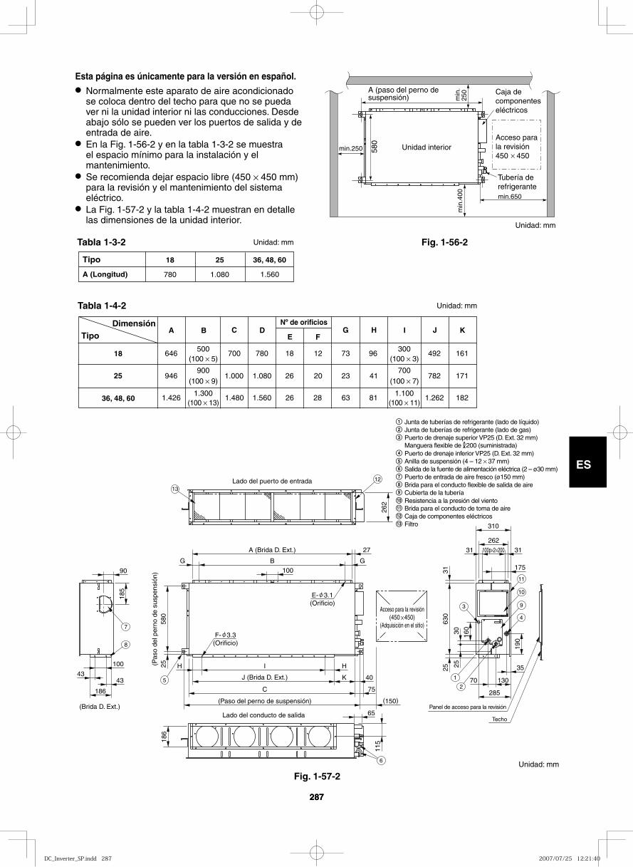
287
ES
287
Fig. 1-56-2
min.250 580
min
.400
A (paso del perno de suspensión) m
in.
250
Unidad interior
min.650
Caja de componenteseléctricos
Acceso para la revisión450 450
Tubería de refrigerante
Tipo
A (Longitud)
36, 48, 60
1.560
25
1.080
18
780
DimensiónTipo
18
25
36, 48, 60
E FG H I J K
646500
700 780 18 12 73 96 492(100 5)
946900
1.000 1.080 26 20 23 41 782(100 9)
1.4261.300
1.480 1.560 26 28 63 81 1.262
161
171
182(100 13)
300(100 3)
700(100 7)
1.100(100 11)
C DBANº de orificios
262
100
580
25 H HI(Pas
o de
l per
no d
e su
spen
sión
)
A (Brida D. Ext.)
Lado del puerto de entrada
(Brida D. Ext.)Lado del conducto de salida
J (Brida D. Ext.)
27
B GG
K 40
C
(Paso del perno de suspensión)
75
(150)
11518
6
65
90
100
4343
185
186
310
262
31100p 2=20031
35
70 130
175
630
3125
190
285
160
2530
Acceso para la revisión(450 450)
(Adquisición en el sitio)
E- 3.1(Orificio)
F- 3.3(Orificio)
Panel de acceso para la revisión
Techo
1
2
3
4
9
10
11
6
5
7
8
12
13
Unidad: mm
Unidad: mm
Junta de tuberías de refrigerante (lado de líquido)Junta de tuberías de refrigerante (lado de gas)Puerto de drenaje superior VP25 (D. Ext. 32 mm)Manguera flexible de 200 (suministrada)Puerto de drenaje inferior VP25 (D. Ext. 32 mm)Anilla de suspensión (4 – 12 37 mm)Salida de la fuente de alimentación eléctrica (2 – ø30 mm)Puerto de entrada de aire fresco (ø150 mm)Brida para el conducto flexible de salida de aireCubierta de la tubería
Brida para el conducto de toma de aireCaja de componentes eléctricos
11Resistencia a la presión del viento10
12
Filtro13
Fig. 1-57-2
Tabla 1-4-2
Tabla 1-3-2
Esta página es únicamente para la versión en español.● Normalmente este aparato de aire acondicionado
se coloca dentro del techo para que no se pueda ver ni la unidad interior ni las conducciones. Desde abajo sólo se pueden ver los puertos de salida y de entrada de aire.
● En la Fig. 1-56-2 y en la tabla 1-3-2 se muestra el espacio mínimo para la instalación y el mantenimiento.
● Se recomienda dejar espacio libre (450 × 450 mm) para la revisión y el mantenimiento del sistema eléctrico.
● La Fig. 1-57-2 y la tabla 1-4-2 muestran en detalle las dimensiones de la unidad interior.
Unidad: mm
Unidad: mm
DC_Inverter_SP.indd 287DC_Inverter_SP.indd 287 2007/07/25 12:21:402007/07/25 12:21:40
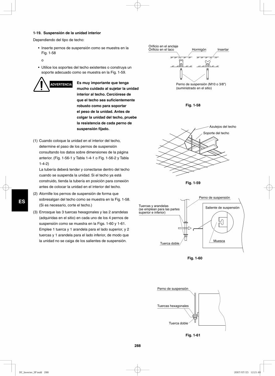
288
ESTuercas y arandelas (se emplean para las partes superior e inferior)
Perno de suspensión
Saliente de suspensión
MuescaTuerca doble
Fig. 1-58
1-19. Suspensión de la unidad interior
Dependiendo del tipo de techo:
• Inserte pernos de suspensión como se muestra en la Fig. 1-58
o
• Utilice los soportes del techo existentes o construya un soporte adecuado como se muestra en la Fig. 1-59.
Orificio en el anclajeOrificio en el taco Hormigón Insertar
Perno de suspensión (M10 o 3/8") (suministrado en el sitio)
Fig. 1-59
Fig. 1-60
Fig. 1-61
Soporte del techo
Azulejos del techo
Tuercas hexagonales
Perno de suspensión
Tuerca doble
(1) Cuando coloque la unidad en el interior del techo,
determine el paso de los pernos de suspensión
consultando los datos sobre dimensiones de la página
anterior. (Fig. 1-56-1 y Tabla 1-4-1 o Fig. 1-56-2 y Tabla
1-4-2)
La tubería deberá tender y conectarse dentro del techo
cuando se suspenda la unidad. Si el techo ya está
construido, tienda la tubería en posición para conexión
antes de colocar la unidad en el interior del techo.
(2) Atornille los pernos de suspensión de forma que
sobresalgan del techo como se muestra en la Fig. 1-58.
(Si es necesario, corte el techo.)
(3) Enrosque las 3 tuercas hexagonales y las 2 arandelas
(adquiridas en el sitio) en cada uno de los 4 pernos de
suspensión como se muestra en la Figs. 1-60 y 1-61.
Emplee 1 tuerca y 1 arandela para el lado superior, y 2
tuercas y 1 arandela para el lado inferior, de modo que
la unidad no se caiga de los salientes de suspensión.
ADVERTENCIA Es muy importante que tenga
mucho cuidado al sujetar la unidad
interior al techo. Cerciórese de
que el techo sea suficientemente
robusto como para soportar
el peso de la unidad. Antes de
colgar la unidad del techo, pruebe
la resistencia de cada perno de
suspensión fijado.
DC_Inverter_SP.indd 288DC_Inverter_SP.indd 288 2007/07/25 12:21:402007/07/25 12:21:40
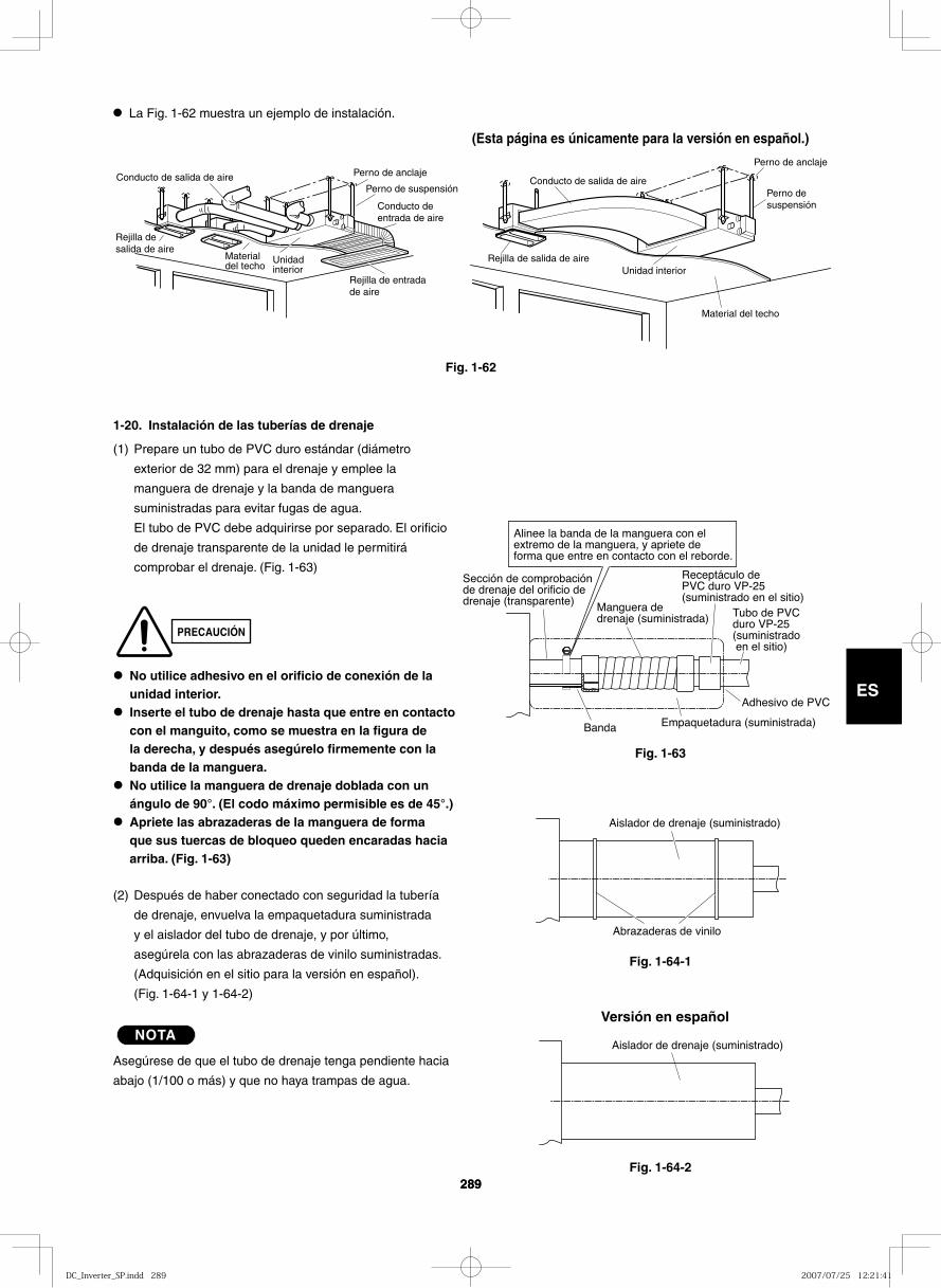
289
ES
289
● La Fig. 1-62 muestra un ejemplo de instalación.
Perno de suspensión
Rejilla de salida de aire
Conducto de salida de aire
Material del techo
Unidadinterior
Perno de anclaje
Conducto de entrada de aire
Rejilla de entrada de aire
Fig. 1-62
Fig. 1-63
Fig. 1-64-1
Tubo de PVC duro VP-25 (suministrado en el sitio)
Adhesivo de PVC
Empaquetadura (suministrada)Banda
Sección de comprobación de drenaje del orificio de drenaje (transparente)
Alinee la banda de la manguera con el extremo de la manguera, y apriete de forma que entre en contacto con el reborde.
Receptáculo de PVC duro VP-25 (suministrado en el sitio)
Manguera de drenaje (suministrada)
Abrazaderas de vinilo
Aislador de drenaje (suministrado)
1-20. Instalación de las tuberías de drenaje
(1) Prepare un tubo de PVC duro estándar (diámetro
exterior de 32 mm) para el drenaje y emplee la
manguera de drenaje y la banda de manguera
suministradas para evitar fugas de agua.
El tubo de PVC debe adquirirse por separado. El orificio
de drenaje transparente de la unidad le permitirá
comprobar el drenaje. (Fig. 1-63)
● No utilice adhesivo en el orificio de conexión de la unidad interior.
● Inserte el tubo de drenaje hasta que entre en contacto con el manguito, como se muestra en la figura de la derecha, y después asegúrelo firmemente con la banda de la manguera.
● No utilice la manguera de drenaje doblada con un ángulo de 90°. (El codo máximo permisible es de 45°.)
● Apriete las abrazaderas de la manguera de forma que sus tuercas de bloqueo queden encaradas hacia arriba. (Fig. 1-63)
(2) Después de haber conectado con seguridad la tubería
de drenaje, envuelva la empaquetadura suministrada
y el aislador del tubo de drenaje, y por último,
asegúrela con las abrazaderas de vinilo suministradas.
(Adquisición en el sitio para la versión en español).
(Fig. 1-64-1 y 1-64-2)
NOTA
Asegúrese de que el tubo de drenaje tenga pendiente hacia
abajo (1/100 o más) y que no haya trampas de agua.
PRECAUCIÓN
Conducto de salida de aire
Rejilla de salida de aire
Material del techo
Unidad interior
Perno de anclaje
Perno de suspensión
(Esta página es únicamente para la versión en español.)
Fig. 1-64-2
Aislador de drenaje (suministrado)
Versión en español
DC_Inverter_SP.indd 289DC_Inverter_SP.indd 289 2007/07/25 12:21:412007/07/25 12:21:41
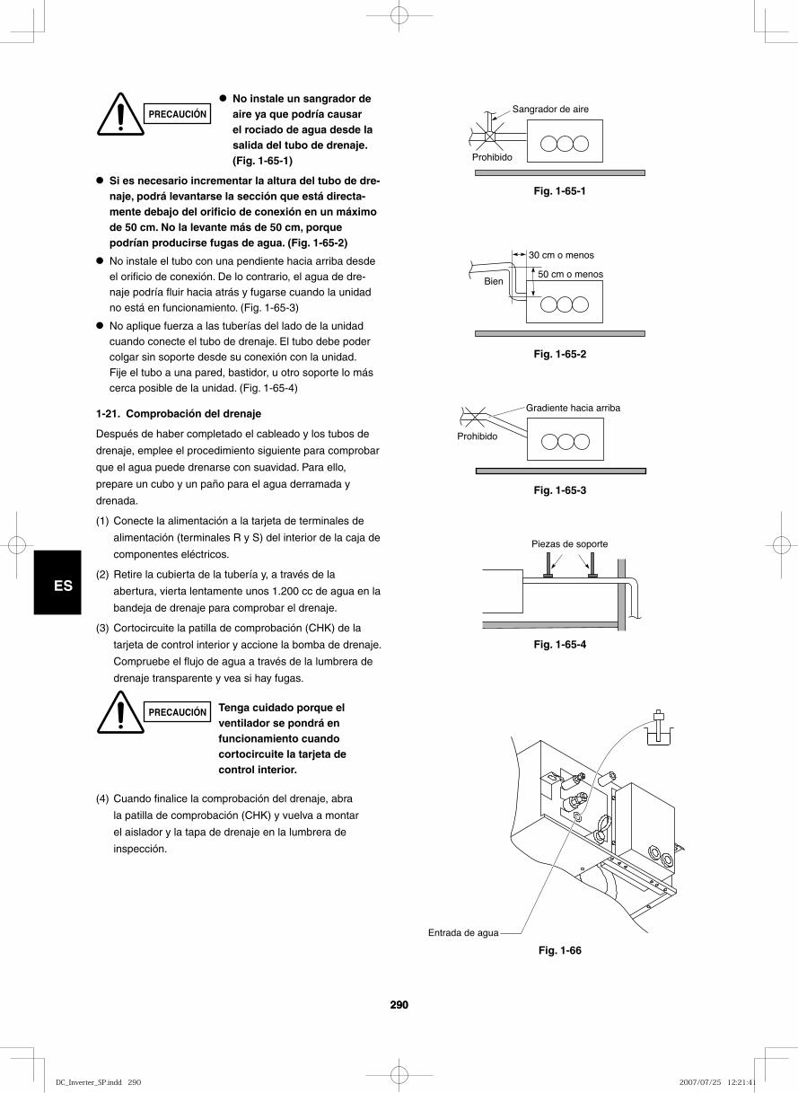
290
ES
290
Fig. 1-65-1
Fig. 1-65-2
Fig. 1-65-3
Fig. 1-65-4
Fig. 1-66
Sangrador de aire
Prohibido
30 cm o menos
50 cm o menosBien
Prohibido
Gradiente hacia arriba
Piezas de soporte
Entrada de agua
● Si es necesario incrementar la altura del tubo de dre-naje, podrá levantarse la sección que está directa-mente debajo del orificio de conexión en un máximo de 50 cm. No la levante más de 50 cm, porque podrían producirse fugas de agua. (Fig. 1-65-2)
● No instale el tubo con una pendiente hacia arriba desde el orificio de conexión. De lo contrario, el agua de dre-naje podría fluir hacia atrás y fugarse cuando la unidad no está en funcionamiento. (Fig. 1-65-3)
● No aplique fuerza a las tuberías del lado de la unidad cuando conecte el tubo de drenaje. El tubo debe poder colgar sin soporte desde su conexión con la unidad. Fije el tubo a una pared, bastidor, u otro soporte lo más cerca posible de la unidad. (Fig. 1-65-4)
1-21. Comprobación del drenaje
Después de haber completado el cableado y los tubos de
drenaje, emplee el procedimiento siguiente para comprobar
que el agua puede drenarse con suavidad. Para ello,
prepare un cubo y un paño para el agua derramada y
drenada.
(1) Conecte la alimentación a la tarjeta de terminales de
alimentación (terminales R y S) del interior de la caja de
componentes eléctricos.
(2) Retire la cubierta de la tubería y, a través de la
abertura, vierta lentamente unos 1.200 cc de agua en la
bandeja de drenaje para comprobar el drenaje.
(3) Cortocircuite la patilla de comprobación (CHK) de la
tarjeta de control interior y accione la bomba de drenaje.
Compruebe el flujo de agua a través de la lumbrera de
drenaje transparente y vea si hay fugas.
(4) Cuando finalice la comprobación del drenaje, abra
la patilla de comprobación (CHK) y vuelva a montar
el aislador y la tapa de drenaje en la lumbrera de
inspección.
● No instale un sangrador de aire ya que podría causar el rociado de agua desde la salida del tubo de drenaje. (Fig. 1-65-1)
PRECAUCIÓN Tenga cuidado porque el ventilador se pondrá en funcionamiento cuando cortocircuite la tarjeta de control interior.
PRECAUCIÓN
DC_Inverter_SP.indd 290DC_Inverter_SP.indd 290 2007/07/25 12:21:412007/07/25 12:21:41
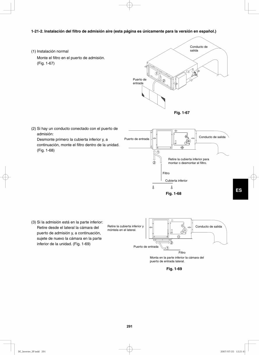
291
ES
(1) Instalación normal
Monte el filtro en el puerto de admisión. (Fig. 1-67)
(2) Si hay un conducto conectado con el puerto de admisión:Desmonte primero la cubierta inferior y, a continuación, monte el filtro dentro de la unidad. (Fig. 1-68)
(3) Si la admisión está en la parte inferior:Retire desde el lateral la cámara del puerto de admisión y, a continuación, sujete de nuevo la cámara en la parte inferior de la unidad. (Fig. 1-69)
Conducto de salida
Puerto de entrada
2
1
Conducto de salidaPuerto de entrada
2
1
Retire la cubierta inferior para montar o desmontar el filtro.
Filtro
Cubierta inferior
Conducto de salida
Puerto de entrada2
1
Monta en la parte inferior la cámara del puerto de entrada lateral.
Filtro
Retire la cubierta inferior y móntela en el lateral.
Fig. 1-67
Fig. 1-68
Fig. 1-69
1-21-2. Instalación del filtro de admisión aire (esta página es únicamente para la versión en español.)
DC_Inverter_SP.indd 291DC_Inverter_SP.indd 291 2007/07/25 12:21:412007/07/25 12:21:41
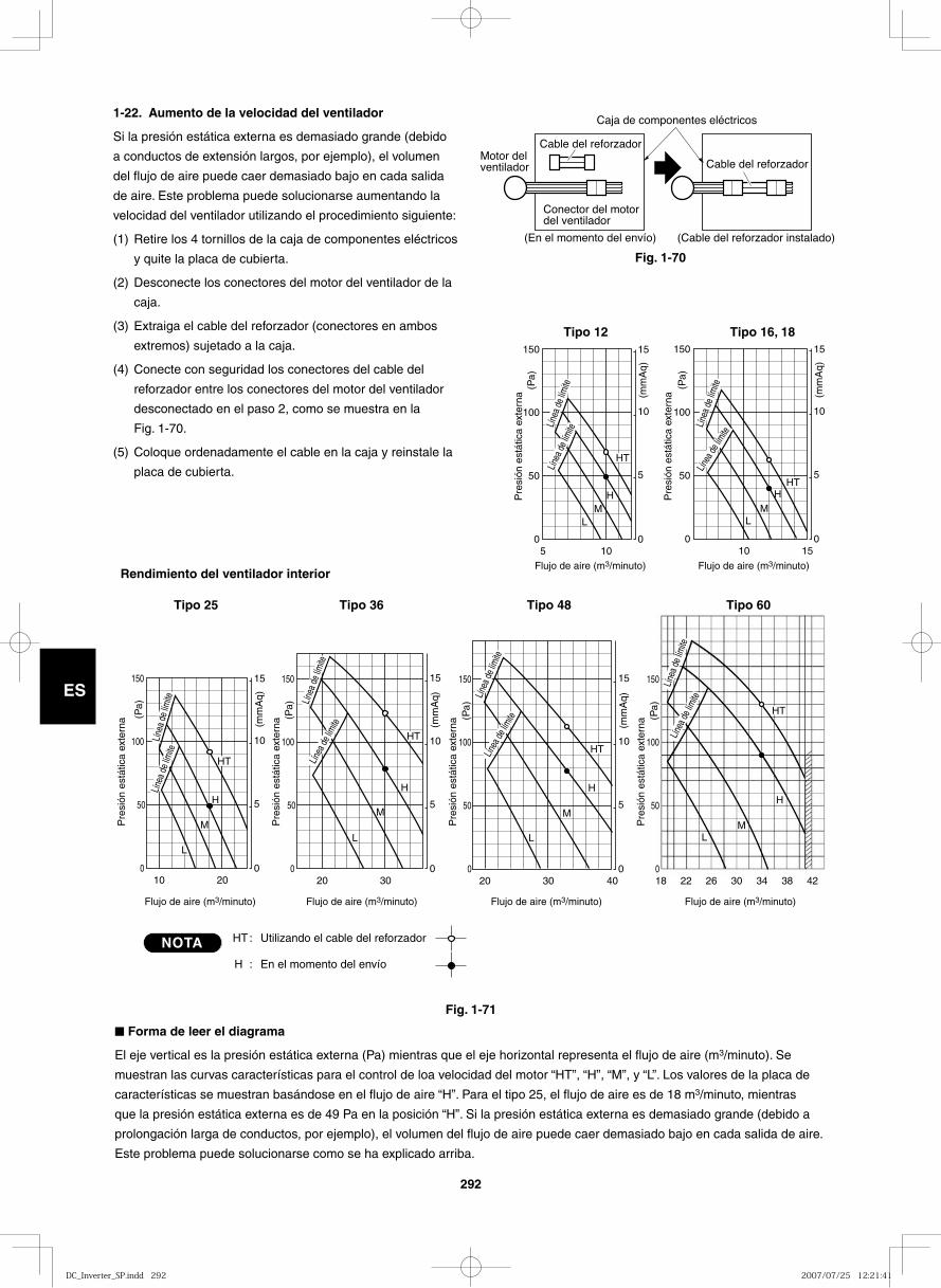
292
ES
1-22. Aumento de la velocidad del ventilador
Si la presión estática externa es demasiado grande (debido
a conductos de extensión largos, por ejemplo), el volumen
del flujo de aire puede caer demasiado bajo en cada salida
de aire. Este problema puede solucionarse aumentando la
velocidad del ventilador utilizando el procedimiento siguiente:
(1) Retire los 4 tornillos de la caja de componentes eléctricos
y quite la placa de cubierta.
(2) Desconecte los conectores del motor del ventilador de la
caja.
(3) Extraiga el cable del reforzador (conectores en ambos
extremos) sujetado a la caja.
(4) Conecte con seguridad los conectores del cable del
reforzador entre los conectores del motor del ventilador
desconectado en el paso 2, como se muestra en la
Fig. 1-70.
(5) Coloque ordenadamente el cable en la caja y reinstale la
placa de cubierta.
Fig. 1-70
Fig. 1-71
Motor del ventilador
Cable del reforzador
Cable del reforzador
Conector del motor del ventilador
(En el momento del envío)
Caja de componentes eléctricos
(Cable del reforzador instalado)
■ Forma de leer el diagrama
El eje vertical es la presión estática externa (Pa) mientras que el eje horizontal representa el flujo de aire (m3/minuto). Se
muestran las curvas características para el control de loa velocidad del motor “HT”, “H”, “M”, y “L”. Los valores de la placa de
características se muestran basándose en el flujo de aire “H”. Para el tipo 25, el flujo de aire es de 18 m3/minuto, mientras
que la presión estática externa es de 49 Pa en la posición “H”. Si la presión estática externa es demasiado grande (debido a
prolongación larga de conductos, por ejemplo), el volumen del flujo de aire puede caer demasiado bajo en cada salida de aire.
Este problema puede solucionarse como se ha explicado arriba.
NOTA
5 0
50
100
0
5
10
15 150
10
(mm
Aq)
(Pa)
HT
H M
L
20 0
50
0
5
10
15 150
10
HT
H
L
100
M
(mm
Aq)
(Pa)
30 40 18 22 26 30 34 38 42 0
50
0
5
10
15 150
20
L
100
M
H
M
H
L
(mm
Aq)
(Pa)
0
50
150
100
(Pa)
HT
HT
30 0
50
0
5
10
15 150
20
HT
L
100
M
H
(mm
Aq)
(Pa)
15 0
50
0
5
10
15 150
10
HT
M L
100
H
(mm
Aq)
(Pa)
Tipo 12 Tipo 16, 18
Tipo 25 Tipo 36 Tipo 48 Tipo 60
Rendimiento del ventilador interior
HT:
H :
Utilizando el cable del reforzador
En el momento del envío
Pre
sión
est
átic
a ex
tern
a
Pre
sión
est
átic
a ex
tern
a
Pre
sión
est
átic
a ex
tern
a
Pre
sión
est
átic
a ex
tern
a
Pre
sión
est
átic
a ex
tern
a
Pre
sión
est
átic
a ex
tern
a
Flujo de aire (m3/minuto)
Flujo de aire (m3/minuto) Flujo de aire (m3/minuto)Flujo de aire (m3/minuto) Flujo de aire (m3/minuto)
Flujo de aire (m3/minuto)
Líne
a de
límite
Línea
de lím
ite Líne
a de
límite
Línea
de lím
ite
Líne
a de
límite
Líne
a de
límite
Líne
a de
límite
Línea
de lím
ite
Línea
de lím
iteLín
ea de
límite
Líne
a de
límite
Línea
de lím
ite
DC_Inverter_SP.indd 292DC_Inverter_SP.indd 292 2007/07/25 12:21:412007/07/25 12:21:41
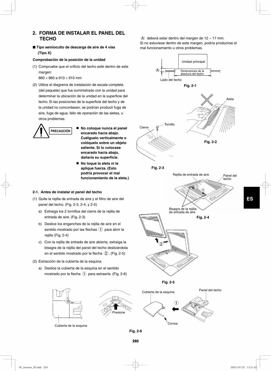
293
ES
293
2. FORMA DE INSTALAR EL PANEL DEL TECHO
■ Tipo semioculto de descarga de aire de 4 vías
(Tipo X)
Comprobación de la posición de la unidad
(1) Compruebe que el orificio del techo esté dentro de este
margen:
860 × 860 a 910 × 910 mm
(2) Utilice el diagrama de instalación de escala completa
(del paquete) que fue suministrado con la unidad para
determinar la ubicación de la unidad en la superficie del
techo. Si las posiciones de la superficie del techo y de
la unidad no concordasen, se podrían producir fuga de
aire, fuga de agua, fallo de operación de las aletas, u
otros problemas.
PRECAUCIÓN● No coloque nunca el panel
encarado hacia abajo. Cuélguelo verticalmente o colóquelo sobre un objeto saliente. Si lo colocase encarado hacia abajo, dañaría su superficie.
● No toque la aleta ni le aplique fuerza. (Esto podría provocar el mal funcionamiento de la aleta.)
A deberá estar dentro del margen de 12 – 17 mm.Si no estuviese dentro de este margen, podría producirse el mal funcionamiento u otros problemas.
A
Unidad principal
Dimensiones de la abertura del techo
Lado del techo
Fig. 2-1
Aleta
Fig. 2-2
Fig. 2-3
2-1. Antes de instalar el panel del techo
(1) Quite la rejilla de entrada de aire y el filtro de aire del
panel del techo. (Fig. 2-3, 2-4, y 2-5)
a) Extraiga los 2 tornillos del cierre de la rejilla de
entrada de aire. (Fig. 2-3)
b) Deslice los enganches de la rejilla de aire en el
sentido mostrado por las flechas 1 para abrir la
rejilla (Fig. 2-4)
c) Con la rejilla de entrada de aire abierta, extraiga la
bisagra de la rejilla del panel del techo deslizándola
en el sentido mostrado por la flecha 2 . (Fig. 2-5)
(2) Extracción de la cubierta de la esquina
a) Deslice la cubierta de la esquina en el sentido
mostrado por la flecha 1 para extraerla. (Fig. 2-6)
1
Cubierta de la esquina
Presione
Cubierta de la esquina
Correa
Panel del techo
Fig. 2-6
CierreTornillo
2
Fig. 2-5
11
Rejilla de entrada de aire Panel del techo
Bisagra de la rejilla de entrada de aire
Fig. 2-4
DC_Inverter_SP.indd 293DC_Inverter_SP.indd 293 2007/07/25 12:21:422007/07/25 12:21:42
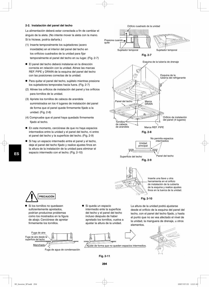
294
ES
294
Superficie del techo
Unidadprincipal
No permita espacios intermedios
Panel del techo
PRECAUCIÓN
2-2. Instalación del panel del techo
La alimentación deberá estar conectada a fin de cambiar el
ángulo de la aleta. (No intente mover la aleta con la mano.
Si lo hiciese, podría dañarla.)
(1) Inserte temporalmente los sujetadores (acero
inoxidable) en el interior del panel del techo en
los orificios cuadrados de la unidad para fijar
temporalmente el panel del techo en su lugar. (Fig. 2-7)
● El panel del techo deberá instalarse en la dirección correcta en relación con la unidad. Alinee las marcas REF. PIPE y DRAIN de la esquina del panel del techo con las posiciones correctas de la unidad.
● Para quitar el panel del techo, sujételo mientras presione los sujetadores temporales hacia fuera. (Fig. 2-7)
(2) Alinee los orificios de instalación del panel y los orificios
para tornillos de la unidad.
(3) Apriete los tornillos de cabeza de arandela
suministrados en los 4 lugares de instalación del panel
de forma que el panel quede firmemente fijado a la
unidad. (Fig. 2-8)
(4) Compruebe que el panel haya quedado firmemente
fijado al techo.
● En este momento, cerciórese de que no haya espacios intermedios entre la unidad y el panel del techo, ni entre el panel del techo y la superficie del techo. (Fig. 2-9)
● Si hay un espacio intermedio entre el panel y el techo, deje el panel del techo fijado y realice ajustes finos en la altura de la instalación de la unidad para eliminar el espacio intermedio con el techo. (Fig. 2-10)
Presione cuando quite
Orificio cuadrado de la unidad
Sujetador temporal Sujetador temporal
Fig. 2-7
Esquina de la tubería de drenaje
Esquina de la tubería del refrigerante
Marca DRAIN
Orificio de instalación del panel (4 lugares)
Marca REF. PIPE
Tornillos de cabeza de arandela
Panel del techo
Fig. 2-8
Fig. 2-9
Inserte una llave u otra herramienta en el orificio de instalación de la cubierta de la esquina y realice ajustes finos en la tuerca de la unidad.
Fuga de aire
Fuga de aire desde la superficie del techo
Manchado
Fuga de agua de condensación
Ajuste de forma que no queden espacios intermedios.
Fig. 2-10
Fig. 2-11
● Si los tornillos no quedasen suficientemente apretados, podrían producirse problemas como los mostrados en la figura de abajo. Cerciórese de apretar firmemente los tornillos.
● Si queda un espacio intermedio ente la superficie del techo y el panel del techo incluso después de haber apretado los tornillos, vuelva a ajustar la altura de la unidad.
La altura de la unidad podrá ajustarse desde el orificio de la esquina del panel del techo, con el panel del techo fijado, y hasta el punto que no se vea afectado el nivel de la unidad, la manguera de drenaje, u otros elementos.
DC_Inverter_SP.indd 294DC_Inverter_SP.indd 294 2007/07/25 12:21:422007/07/25 12:21:42
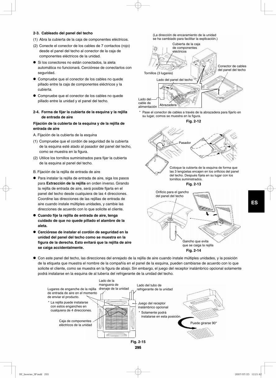
295
ES
295
2-3. Cableado del panel del techo
(1) Abra la cubierta de la caja de componentes eléctricos.
(2) Conecte el conector de los cables de 7 contactos (rojo) desde el panel del techo al conector de la caja de componentes eléctricos de la unidad.
● Si los conectores no están conectados, la aleta automática no funcionará. Cerciórese de conectarlos con seguridad.
● Compruebe que el conector de los cables no quede pillado entre la caja de componentes eléctricos y la cubierta.
● Compruebe que el conector de los cables no quede pillado entre la unidad y el panel del techo.
2-4. Forma de fijar la cubierta de la esquina y la rejilla de entrada de aire
Fijación de la cubierta de la esquina y de la rejilla de entrada de aire
A. Fijación de la cubierta de la esquina
(1) Compruebe que el cordón de seguridad de la cubierta de la esquina esté atado al pasador del panel del techo, como se muestra en la figura.
(2) Utilice los tornillos suministrados para fijar la cubierta de la esquina al panel del techo.
B. Fijación de la rejilla de entrada de aire
● Para instalar la rejilla de entrada de aire, siga los pasos para Extracción de la rejilla en orden inverso. Girando la rejilla de entrada de aire, será posible fijarla en el panel del techo desde cualquiera de las 4 direcciones. Coordine las direcciones de las rejillas de entrada de aire cuando instale múltiples unidades, y cambie las direcciones de acuerdo con lo que solicite el cliente.
● Cuando fije la rejilla de entrada de aire, tenga cuidado de que no quede pillado el alambre de la aleta.
● Cerciórese de instalar el cordón de seguridad en la unidad del panel del techo como se muestra en la figura de la derecha. Esto evitará que la rejilla de aire se caiga accidentalmente.
(La dirección de encaramiento de la unidad se ha cambiado para facilitar la explicación.)
Cubierta de la caja de componentes eléctricos
Tornillos (3 lugares)
Lado del panel del techo
Conector de cables del panel del techo
Lado del cable de alimentación
Pase el conector de cables a través de la abrazadera para fijarlo en su lugar, comos se muestra en la figura.
*
Abrazadera
Pasador
Coloque la cubierta de la esquina de forma que las 3 lengüetas encajen en los orificios del panel del techo. Después fíjela en su lugar con los tornillos suministrados.
Lugares de enganche de la rejilla de entrada de aire en el momento de enviar el producto.
La rejilla puede instalarse con estos enganches en cualquiera de 4 direcciones.
* Juego del receptor inalámbrico opcional
Solamente podrá instalarse en esta posición.
*
Lado de la manguera de drenaje de la unidad
Lado del tubo de refrigerante de la unidad
Puede girarse 90°Caja de componentes eléctricos de la unidad
Fig. 2-12
Fig. 2-13
Orificio para el gancho del panel del techo
Gancho que evita que se caiga la rejilla
Fig. 2-14
Fig. 2-15
● Con este panel del techo, las direcciones del enrejado de la rejilla de aire cuando instale múltiples unidades, y la posición de la etiqueta que muestra el nombre de la compañía en el panel de la esquina, pueden cambiarse de acuerdo con lo que solicite el cliente, como se muestra en la figura de abajo. Sin embargo, el juego del receptor inalámbrico opcional solamente podrá instalarse en la esquina de al tubería del refrigerante de la unidad del techo.
DC_Inverter_SP.indd 295DC_Inverter_SP.indd 295 2007/07/25 12:21:422007/07/25 12:21:42
296
ES
2-5. Comprobación después de la instalación
● Compruebe que no queden espacios intermedios entre la unidad y el panel del techo, ni entre el panel del techo y la superficie del techo. Los espacios intermedios podrían causar fugas y condensación de agua.
● Compruebe que los cables hayan quedado conectados con seguridad. Si no quedasen conectados con seguridad, la aleta automática no funcionaría. (En el mando a distancia se visualizaría “P09”.) Además, podría producirse fuga y condensación de agua.
2-6. Cuando extraiga el panel del techo para el servicio
de mantenimiento
Cuando extraiga el panel del techo para el servicio de
mantenimiento, extraiga la rejilla de entrada de aire y el
filtro de aire, desconecte el conector de los cables del
interior de la caja de componentes eléctricos, y extraiga los
4 tornillos de montaje.
2-7. Ajuste de la aleta automática
La celosía de dirección del aire de la salida del panel del
techo puede ajustarse de la forma siguiente.
● Ajuste la celosía al ángulo deseado utilizando el mando a distancia. La celosía tiene también un mecanismo de barrido de aire automático.
NOTA● No intente nunca mover la celosía con la mano.
● El flujo de aire apropiado depende de la ubicación del acondicionador de aire, la distribución y el mobiliario de la habitación, etc. Si la refrigeración o la calefacción parecen inadecuadas, pruebe cambiando la dirección del flujo de aire.
DC_Inverter_SP.indd 296DC_Inverter_SP.indd 296 2007/07/25 12:21:432007/07/25 12:21:43