Embed Size (px)
Citation preview
INVESTIGATION OF HYBRID AND DIFFERENT CROSS-SECTION COMPOSITE DISCSPRINGS USING FINITE ELEMENT METHOD
Sükrü KarakayaAfyon Kocatepe University, Technical Education Faculty, ANS Campus, Afyonkarahisar, Turkey
E-mail: [email protected]
Received May 2012, Accepted November 2012No. 12-CSME-62, E.I.C. Accession 3382
ABSTRACTIn this study the effectiveness of composite disc springs with different cross-section and hybrid type are
determined by taking into account load capacities, masses, hybridization characteristics and costs of com-posite disc springs. The disc springs are analyzed with ABAQUS finite elements program by compressingbetween two rigid plates. The load-deflection characteristics obtained as a result of the analysis are com-pared with the analytic and experimental studies. Then different cross-section and hybrid composite discsprings were modeled. The trapeze A disc spring were confirmed to be more advantageous in terms ofload capacity and mass by investigating the modeled disc springs. The effect of hybridization on hybriddisc springs with standard cross-section was investigated and optimum hybrid disc spring was determinedaccording to cost and maximum loading capacity. Consequently, it is determined that carbon/epoxy pliesused for outer layers are more advantageous. But the outer ply subjected to force was damaged thus thislayer should be particularly reinforced.
Keywords: disc spring; hybridization; FEM; carbon fiber.
ÉTUDE DE RONDELLES RESSORTS EN MATÉRIAUX COMPOSITES HYBRIDES ET DEDIFFÉRENTES SECTIONS CROISÉES UTILISANT LA MÉTHODE DES ÉLÉMENTS FINIS
RÉSUMÉDans cette étude, l’efficacité des rondelles ressorts en matériaux composites de type différent en section
croisé et hybride est déterminée, en prenant en considération la capacité de charge, la masse, les caracté-ristiques d’hybridation et le coût. Les rondelles ressorts sont analysées à l’aide de ABAQUS, progiciel decalcul des éléments finis, en compressant deux plaques rigides. Les caractéristiques de flexion en chargeobtenues sont comparées avec les études analytiques et expérimentales. En outre, les rondelles optimalessont déterminées selon le coût et la capacité de charge maximale.
Mots-clés : rondelle ressort ; hybridation ; FEM ; fibre de carbone.
Transactions of the Canadian Society for Mechanical Engineering, Vol. 36, No. 4, 2012 399
1. INTRODUCTION
The use of composite materials in advanced engineering applications has been gradually increasing due tohigh strength and stable material characteristics. The composite materials, which have better light-weight,rigidity and several special characteristics, are preferred for aerospace, automotive and maritime vehicles.This applies to springs made up of metal alloys. There materials are replaced with composite springs man-ufactured with synthetic fibers or natural fibers. The applications frequently included in the literature forcomposite springs are leaf, helical and disc spring applications.
One of the significant advantages of composite leaf springs is that composite leaf springs have betterstrength and elastic energy, in comparison to leaf springs made of steel. Besides, strength/weight ratioof composite leaf springs is more than the steel springs. The researchers design and analyze compositesprings, rather than metal leaf springs used in the past [1]. The studies conducted by researchers managedto significantly reduce the stress on spring and structure weight. The leaf springs produced with reinforcedglass fiber used on different road conditions and achieved significant reduction in noise in the cabin andspring stiffness, in comparison to leaf spring made of metal [2]. Mahdi et al. developed an elliptic compositespring in order to lighten the suspension systems of heavy trucks which are heavy. The effect of elliptic ratioon composite spring was examined experimentally and numerically. Besides, it was determined that ellipticratio has significant impact on spring constant and failure condition [3]. In hybrid leaf spring study, glassand other fibers were homogenously distributed in a certain cell and composite leaf springs were producedwithout laminating, by using glass and other fibers. A uniform stress distribution was achieved on theleaf spring produced [4]. Another application related to production of springs from composite materials ishelical spring application. The study compared helical springs produced in different types and as a result,increase in spring constant and reduction in compression failure were ensured. Sancaktar and Goweishangerconducted another study on helical springs. Spring rigidity of helical springs produced in glass, carbon andhybrid form was determined experimentally. The effects of coil diameter, wire diameter and coil numberon spring rigidity were determined and also feasibility of replacing standard steel spring with compositehelical spring were examined [5–7]. The characteristics of steel disc springs were examined analyticallyand experimentally studies related to disc springs which are compression springs. Besides, the weight ofdisc spring was reduced by using woven carbon/epoxy. Another study targeted reducing weight. The goalwas to achieve a force-deflection curve, like that of a steel spring, with a lighter disc [8,9].
The main purpose of this study was to determine the effectiveness of hybrid and different sectional discsprings. Load capacities, masses, hybridization characteristics and costs of the composite disc springs weretaken into consideration on this study. In this study has three main parts. First, disc springs subjected tocompression load were modeled by ABAQUS finite elements program. The load-deflection characteristicsachieved as a result of compression analysis were compared with analytical and experimental studies. Thendisc springs having different cross-section geometry were modeled. These disc springs were compared witheach other according to their low mass — high load capacity. Finally, the standard cross-section hybriddisc springs made up of carbon/epoxy and glass/epoxy plies were modeled. The hybrid disc springs werecompared in terms of load capacity and costs and the disc spring was confirmed to be the optimum. Failurecondition of optimum hybrid disc spring was determined and results associated with this condition wereobtained.
2. DISC SPRING AND THEORY
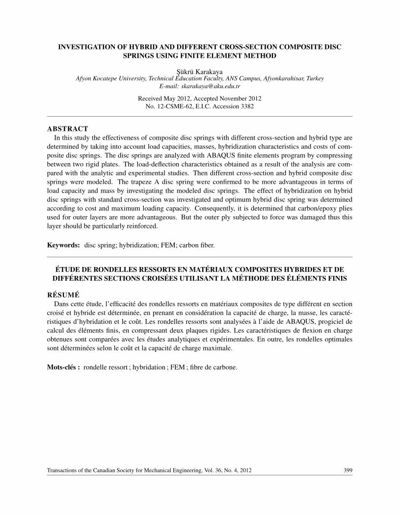
Conical disc springs are axial compression spring (see Fig. 1). They are used machines where large forcesare required and small deflections are desired. Also machines transmitting mechanic power, turbines, jetmotors and space applications are other areas to use disc springs [4,9]. Disc springs have several advantagesdistinguishing them from standard springs. These advantages can be listed as follows:
400 Transactions of the Canadian Society for Mechanical Engineering, Vol. 36, No. 4, 2012
• Offers high load in small spaces.
• Offers any desired spring length or spring characteristics by adding or removing any number in astack.
• Offers longer service life under dynamic loads with a suitable sizing.
• Various application opportunities due to load / deflection characteristics.
• No undesired loosening that that might incur excessive stress stress.
As for standard disc springs, Almen and Laszlo conducted a substantial study on disc springs. They ex-pressed effects of basic geometric characteristics, such as conic height, thickness, in spring characteristicswith analytical equations and experimentally [8]. Dharan and Bauman conducted compression test on com-posite disc springs made up of woven carbon/epoxy material having quasi-isotropic plies. The study exam-ined the feasibility of replacing standard steel springs with composite disc springs. The experiment sampleswith different ho heights were produced and load-deflection curves of those were obtained. The study de-termined that significant mass saving will be achieved by using composite disc springs [9]. Another studyrealized on disc springs examined disc springs having standard cross-section and different cross-sectiongeometry by using finite elements method. The study carried out non-linear compression analysis on discsprings. Stress characteristics of disc spring section were examined. Another study conducted on discsprings having different cross-section examined anisotropic disc springs. Load-deflection curves of discsprings achieved with different laminating were compared. The anisotropic cross-section study confirmedthat the load-deflection curve is approximately 50 % better than the glass/epoxy disc spring with standardsection [10,11].
Fig. 1. Disc spring and section characteristics.
Disc spring and section characteristics are given in Fig. 1. Here, ho is the maximum conic height ofdeflection, Do is the outside diameter, Di is the inside diameter, h is the total height, t is the thickness of discspring and Dr is the centre of rotation of the disc spring’s section.
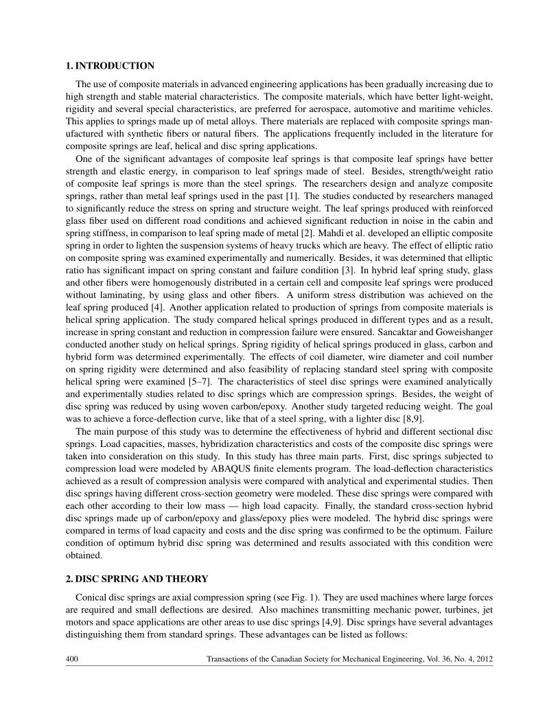
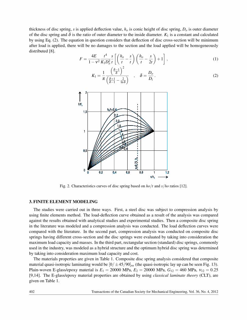
Figure 2 shows the spring characteristics obtained depending on the deflection/conic height and conicheight/thickness (s/ho and ho/t) values of disc springs [12]. In high ho/t ratios, the disc spring reaches upto a certain peak point and then is subjected to a negative trend. In case of ho/t = 1.4 and subsequent values,disc spring displays instable characteristics after a certain deflection. If linear load-deflection is required,then ho/t ratio should be 1 or less.
The compression force of disc springs are expressed with the Eq. (1). This formula was suggested byAlmen and Laszlo. In the equation, E is elasticity module of the material, v is the Poisson ratio, t is
Transactions of the Canadian Society for Mechanical Engineering, Vol. 36, No. 4, 2012 401
thickness of disc spring, s is applied deflection value, ho is conic height of disc spring, Do is outer diameterof the disc spring and δ is the ratio of outer diameter to the inside diameter. K1 is a constant and calculatedby using Eq. (2). The equation in question considers that deflection of disc cross-section will be minimumafter load is applied, there will be no damages to the section and the load applied will be homogeneouslydistributed [8].
F =4E
1−ν2t4
K1D2o
st
[(ho
t− s
t
)(ho
t− s
2t
)+1], (1)
K1 =1π
(δ−1
δ
)2(δ+1δ−1 −
2lnδ
) , δ =Do
Di. (2)
Fig. 2. Characteristics curves of disc spring based on ho/t and s/ho ratios [12].
3. FINITE ELEMENT MODELING
The studies were carried out in three ways. First, a steel disc was subject to compression analysis byusing finite elements method. The load-deflection curve obtained as a result of the analysis was comparedagainst the results obtained with analytical studies and experimental studies. Then a composite disc springin the literature was modeled and a compression analysis was conducted. The load deflection curves werecompared with the literature. In the second part, compression analysis was conducted on composite discsprings having different cross-section and the disc springs were evaluated by taking into consideration themaximum load capacity and masses. In the third part, rectangular section (standard) disc springs, commonlyused in the industry, was modeled as a hybrid structure and the optimum hybrid disc spring was determinedby taking into consideration maximum load capacity and cost.
The materials properties are given in Table 1. Composite disc spring analysis considered that compositematerial quasi-isotropic laminating would be [0/±45/90]ns (the quasi-isotropic lay up can be seen Fig. 13).Plain-woven E-glass/epoxy material is E1 = 20000 MPa, E2 = 20000 MPa, G12 = 460 MPa, ν12 = 0.25[9,14]. The E-glass/epoxy material properties are obtained by using classical laminate theory (CLT), aregiven on Table 1.
402 Transactions of the Canadian Society for Mechanical Engineering, Vol. 36, No. 4, 2012
Materials E1 = E2 (MPa) ν12 ρ (kg/m3)
Carbon/epoxy 48 000 0.30 1450 E-Glass/epoxy* 17 850 0.38 1800
Steel 210 000 0.30 7800
*Used formulas in the Appendix.
Table 1
Mechanical properties Glass/epoxy T3000, carbon/epoxy 94 gsm
Longitudinal modulu, E1 = E2 (MPa) 20 000 56 000
Poisson’s ratio, ν12 0.25 0.05
Shear modulu, G12 (MPa) 461 3000
Tensile strength, ,L TS S+ + (MPa) 473 650
Compressive strength, ,L TS S− − (MPa) 473 670
Shear strength, LTS (MPa) 85 111
Table 2
Table 1. Disc spring material properties [9,14].
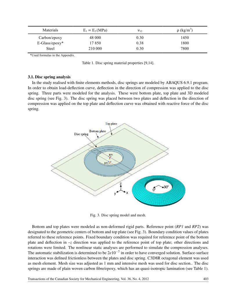
3.1. Disc spring analysisIn the study realised with finite elements methods, disc springs are modeled by ABAQUS 6.9.1 program.
In order to obtain load-deflection curve, deflection in the direction of compression was applied to the discspring. Three parts were modeled for the analysis. These were bottom plate, top plate and 3D modeleddisc spring (see Fig. 3). The disc spring was placed between two plates and deflection in the direction ofcompression was applied on the top plate and deflection curve was obtained with reactive force of the discspring.
Fig. 3. Disc spring model and mesh.
Bottom and top plates were modeled as non-deformed rigid parts. Reference point (RP1 and RP2) wasdesignated to the geometric centers of bottom and top plate (see Fig. 3). Boundary condition values of platesreferred to these reference points. Fixed boundary condition was required for reference point of the bottomplate and deflection in –z direction was applied to the reference point of top plate; other directions androtations were limited. The nonlinear static analyses are performed to simulate the compression analyses.The automatic stabilization is determined to be 2e10−7 in order to have converged solution. Surface-surfaceinteraction was defined frictionless between the plates and disc spring. C3D8R octagonal element was usedas mesh element. Mesh size was adjusted as 1 mm and intensive mesh was used for disc section.. The discsprings are made of plain woven carbon fibre/epoxy, which has an quasi-isotropic lamination (see Table 1).
Transactions of the Canadian Society for Mechanical Engineering, Vol. 36, No. 4, 2012 403
The lamination has not been applied the 3D to model for sections 3.1, 3.2 and 3.3. The plain woven carbonfibre/epoxy plies are layered [XZ] plane. The dimensions of the composite disc spring are as following:Do = 51.4 mm, Di = 24.3 mm, ho = 6.7 mm, t = 3.4 mm [9].
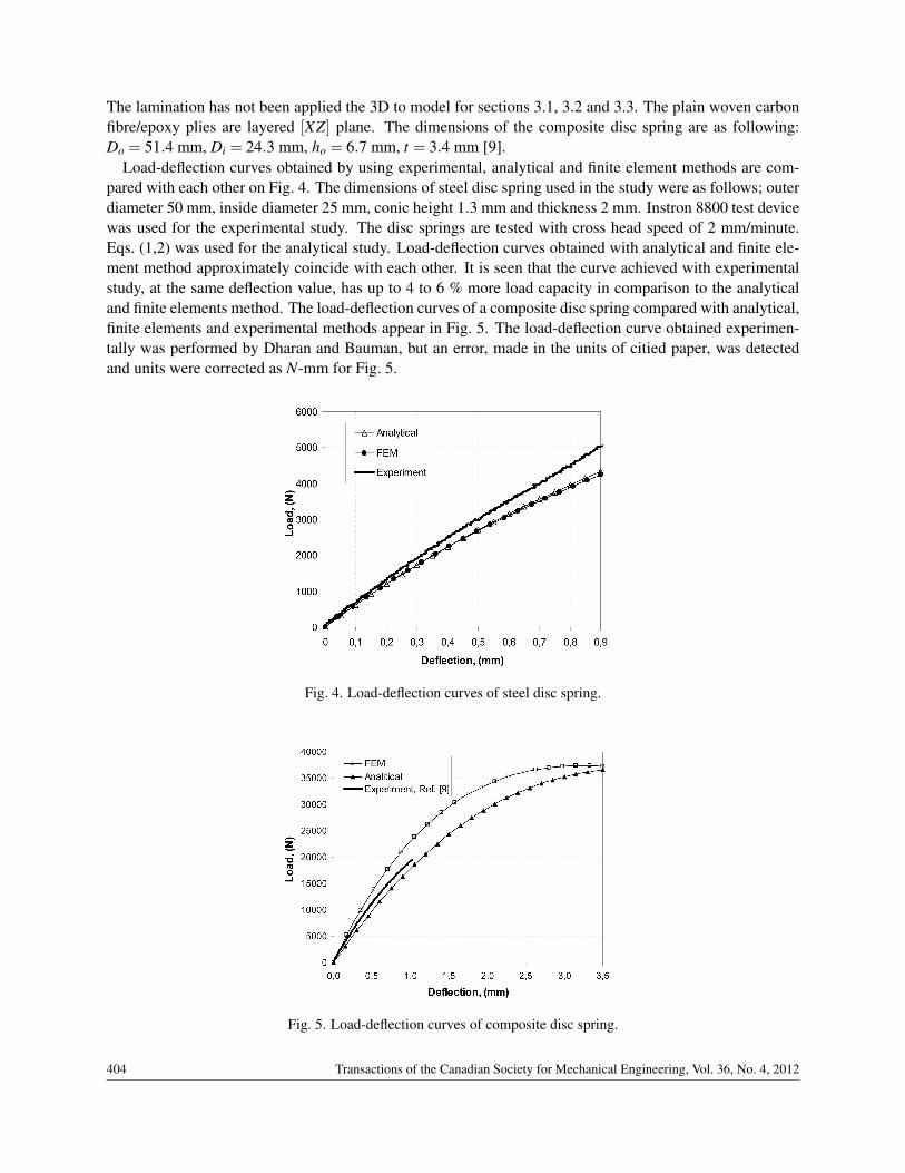
Load-deflection curves obtained by using experimental, analytical and finite element methods are com-pared with each other on Fig. 4. The dimensions of steel disc spring used in the study were as follows; outerdiameter 50 mm, inside diameter 25 mm, conic height 1.3 mm and thickness 2 mm. Instron 8800 test devicewas used for the experimental study. The disc springs are tested with cross head speed of 2 mm/minute.Eqs. (1,2) was used for the analytical study. Load-deflection curves obtained with analytical and finite ele-ment method approximately coincide with each other. It is seen that the curve achieved with experimentalstudy, at the same deflection value, has up to 4 to 6 % more load capacity in comparison to the analyticaland finite elements method. The load-deflection curves of a composite disc spring compared with analytical,finite elements and experimental methods appear in Fig. 5. The load-deflection curve obtained experimen-tally was performed by Dharan and Bauman, but an error, made in the units of citied paper, was detectedand units were corrected as N-mm for Fig. 5.
Fig. 4. Load-deflection curves of steel disc spring.
Fig. 5. Load-deflection curves of composite disc spring.
404 Transactions of the Canadian Society for Mechanical Engineering, Vol. 36, No. 4, 2012
The disc springs are made of plain woven carbon fibre/epoxy, which has an quasi-isotropic laminates(see Table 1). The dimensions of the composite disc spring are as follows: Do = 51.4 mm, Di = 24.3 mm,ho = 6.7 mm, t = 3.4 mm [9]. The load-deflection curve of the study conducted with finite elements methodis different from the analytical study and non-linearity has increased. There is a 8 to 10 % difference betweenthe experimental study and finite elements method. As seen on Fig. 2, the non-linearity of load-deflectioncurve increases in parallel to the increase of conic height of disc springs.
3.2. Disc springs with different cross-section
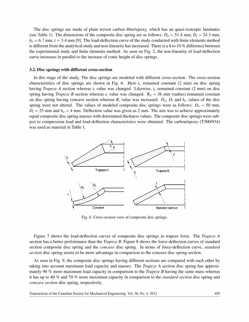
In this stage of the study, The disc springs are modeled with different cross-section. The cross-sectioncharacteristics of disc springs are shown in Fig. 6. Here te remained constant (2 mm) on disc springhaving Trapeze A section whereas ti value was changed. Likewise, te remained constant (2 mm) on discspring having Trapeze B section whereas ti value was changed. Rd = 36 mm (radius) remained constanton disc spring having concave section whereas Ri value was increased. Do, Di and ho values of the discspring were not altered. The values of modeled composite disc springs were as follows: Do = 50 mm,Di = 25 mm and ho = 4 mm. Deflection value was given as 2 mm. The aim was to achieve approximatelyequal composite disc spring masses with determined thickness values. The composite disc springs were sub-ject to compression load and load-deflection characteristics were obtained. The carbon/epoxy (T300/934)was used as material in Table 1.
Fig. 6. Cross-section view of composite disc springs.
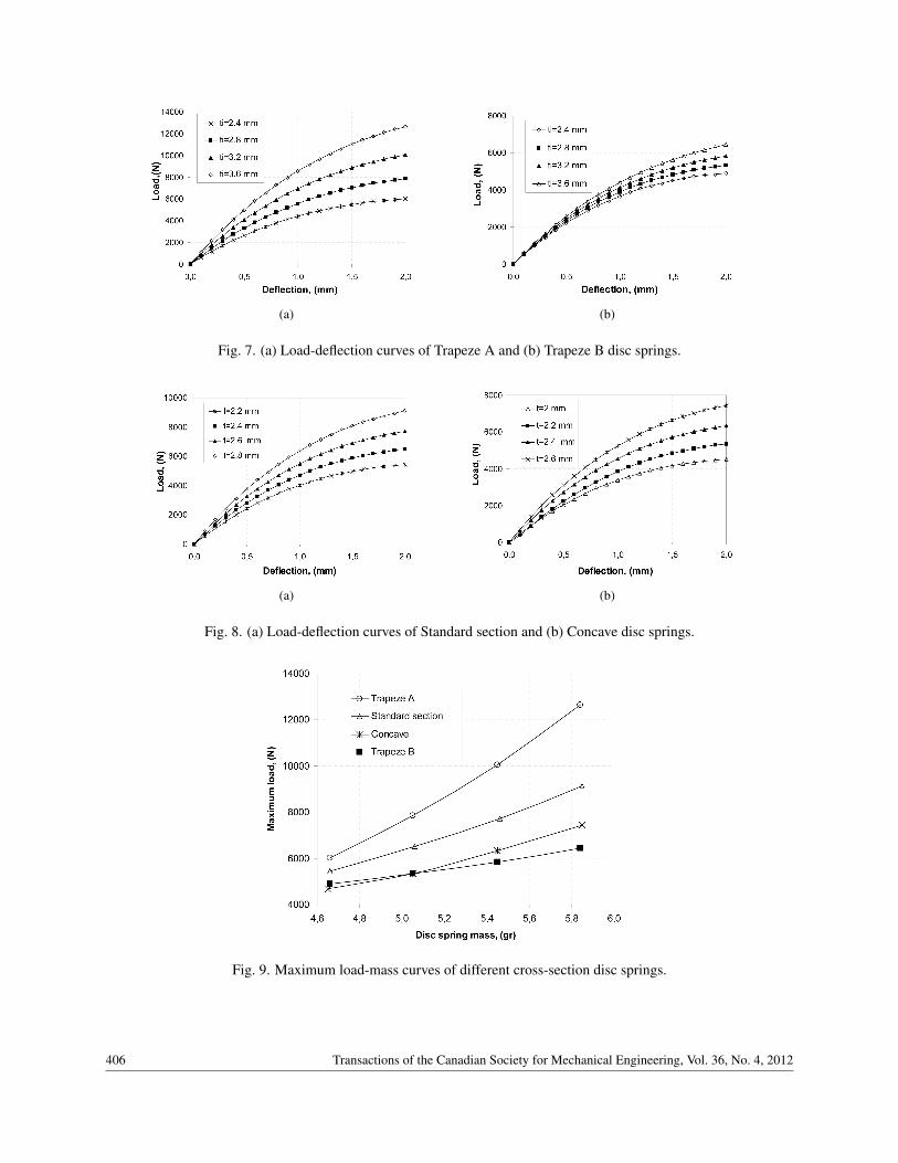
Figure 7 shows the load-deflection curves of composite disc springs in trapeze form. The Trapeze Asection has a better performance than the Trapeze B. Figure 8 shows the force-deflection curves of standardsection composite disc spring and the concave disc spring. In terms of force-deflection curve, standardsection disc spring seems to be more advantage in comparison to the concave disc spring section.
As seen in Fig. 9, the composite disc springs having different sections are compared with each other bytaking into account maximum load capacity and masses. The Trapeze A section disc spring has approxi-mately 90 % more maximum load capacity in comparison to the Trapeze B having the same mass whereasit has up to 40 % and 70 % more maximum capacity in comparison to the standard section disc spring andconcave section disc spring, respectively.
Transactions of the Canadian Society for Mechanical Engineering, Vol. 36, No. 4, 2012 405
(a) (b)
Fig. 7. (a) Load-deflection curves of Trapeze A and (b) Trapeze B disc springs.
(a) (b)
Fig. 8. (a) Load-deflection curves of Standard section and (b) Concave disc springs.
Fig. 9. Maximum load-mass curves of different cross-section disc springs.
406 Transactions of the Canadian Society for Mechanical Engineering, Vol. 36, No. 4, 2012
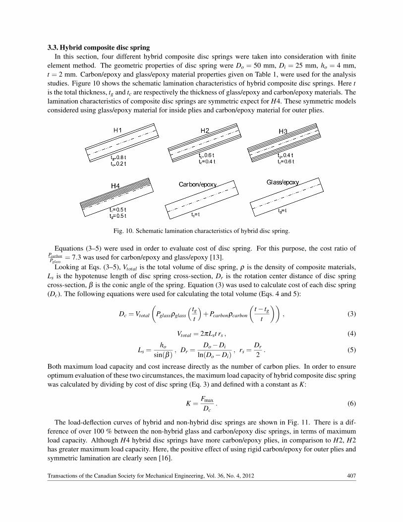
3.3. Hybrid composite disc springIn this section, four different hybrid composite disc springs were taken into consideration with finite
element method. The geometric properties of disc spring were Do = 50 mm, Di = 25 mm, ho = 4 mm,t = 2 mm. Carbon/epoxy and glass/epoxy material properties given on Table 1, were used for the analysisstudies. Figure 10 shows the schematic lamination characteristics of hybrid composite disc springs. Here tis the total thickness, tg and tc are respectively the thickness of glass/epoxy and carbon/epoxy materials. Thelamination characteristics of composite disc springs are symmetric expect for H4. These symmetric modelsconsidered using glass/epoxy material for inside plies and carbon/epoxy material for outer plies.
Fig. 10. Schematic lamination characteristics of hybrid disc spring.
Equations (3–5) were used in order to evaluate cost of disc spring. For this purpose, the cost ratio ofPcarbonPglass
= 7.3 was used for carbon/epoxy and glass/epoxy [13].Looking at Eqs. (3–5), Vtotal is the total volume of disc spring, ρ is the density of composite materials,
Ls is the hypotenuse length of disc spring cross-section, Dr is the rotation center distance of disc springcross-section, β is the conic angle of the spring. Equation (3) was used to calculate cost of each disc spring(Dc). The following equations were used for calculating the total volume (Eqs. 4 and 5):
Dc =Vtotal
(Pglassρglass
( tgt
)+Pcarbonρcarbon
(t − tg
t
)), (3)
Vtotal = 2πLst rs , (4)
Ls =ho
sin(β ), Dr =
Do −Di
ln(Do −Di), rs =
Dr
2. (5)
Both maximum load capacity and cost increase directly as the number of carbon plies. In order to ensureoptimum evaluation of these two circumstances, the maximum load capacity of hybrid composite disc springwas calculated by dividing by cost of disc spring (Eq. 3) and defined with a constant as K:
K =Fmax
Dc. (6)
The load-deflection curves of hybrid and non-hybrid disc springs are shown in Fig. 11. There is a dif-ference of over 100 % between the non-hybrid glass and carbon/epoxy disc springs, in terms of maximumload capacity. Although H4 hybrid disc springs have more carbon/epoxy plies, in comparison to H2, H2has greater maximum load capacity. Here, the positive effect of using rigid carbon/epoxy for outer plies andsymmetric lamination are clearly seen [16].
Transactions of the Canadian Society for Mechanical Engineering, Vol. 36, No. 4, 2012 407
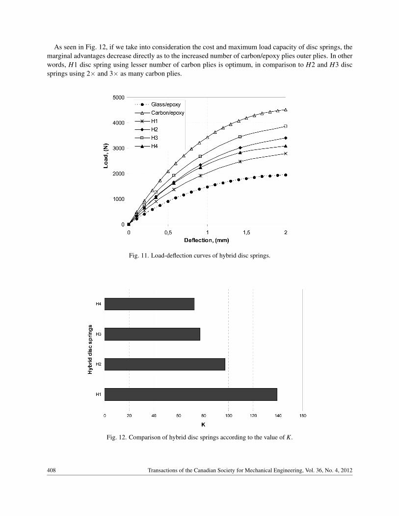
As seen in Fig. 12, if we take into consideration the cost and maximum load capacity of disc springs, themarginal advantages decrease directly as to the increased number of carbon/epoxy plies outer plies. In otherwords, H1 disc spring using lesser number of carbon plies is optimum, in comparison to H2 and H3 discsprings using 2× and 3× as many carbon plies.
Fig. 11. Load-deflection curves of hybrid disc springs.
Fig. 12. Comparison of hybrid disc springs according to the value of K.
408 Transactions of the Canadian Society for Mechanical Engineering, Vol. 36, No. 4, 2012
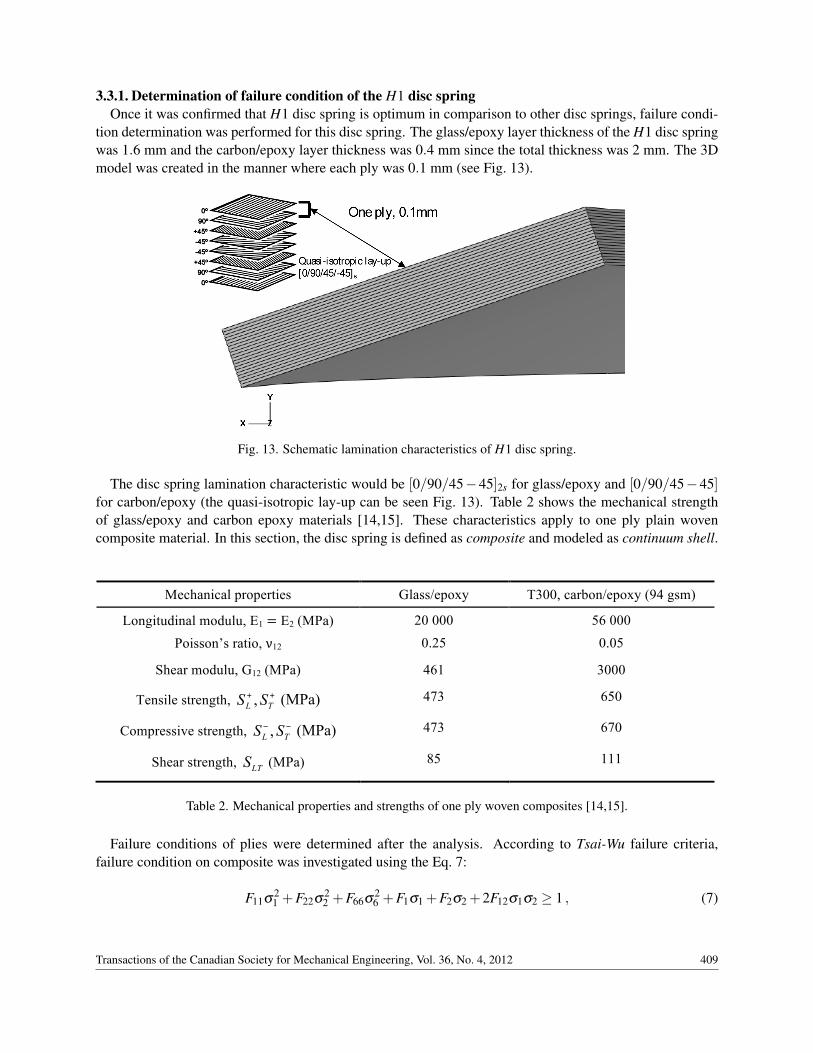
3.3.1. Determination of failure condition of the H1 disc springOnce it was confirmed that H1 disc spring is optimum in comparison to other disc springs, failure condi-
tion determination was performed for this disc spring. The glass/epoxy layer thickness of the H1 disc springwas 1.6 mm and the carbon/epoxy layer thickness was 0.4 mm since the total thickness was 2 mm. The 3Dmodel was created in the manner where each ply was 0.1 mm (see Fig. 13).
Fig. 13. Schematic lamination characteristics of H1 disc spring.
The disc spring lamination characteristic would be [0/90/45−45]2s for glass/epoxy and [0/90/45−45]for carbon/epoxy (the quasi-isotropic lay-up can be seen Fig. 13). Table 2 shows the mechanical strengthof glass/epoxy and carbon epoxy materials [14,15]. These characteristics apply to one ply plain wovencomposite material. In this section, the disc spring is defined as composite and modeled as continuum shell.
Materials E1 = E2 (MPa) ν12 ρ (kg/m3)
Carbon/epoxy 48 000 0.30 1450 E-Glass/epoxy* 17 850 0.38 1800
Steel 210 000 0.30 7800
*Used formulas in the Appendix.
Table 1
Mechanical properties Glass/epoxy T300, carbon/epoxy (94 gsm)
Longitudinal modulu, E1 = E2 (MPa) 20 000 56 000
Poisson’s ratio, ν12 0.25 0.05
Shear modulu, G12 (MPa) 461 3000
Tensile strength, ,L TS S+ + (MPa) 473 650
Compressive strength, ,L TS S− − (MPa) 473 670
Shear strength, LTS (MPa) 85 111
Table 2 Table 2. Mechanical properties and strengths of one ply woven composites [14,15].
Failure conditions of plies were determined after the analysis. According to Tsai-Wu failure criteria,failure condition on composite was investigated using the Eq. 7:
F11σ21 +F22σ
22 +F66σ
26 +F1σ1 +F2σ2 +2F12σ1σ2 ≥ 1 , (7)
Transactions of the Canadian Society for Mechanical Engineering, Vol. 36, No. 4, 2012 409
in which F11 = 1/(S+L S−L ), F22 = 1/(S+T S−T ), F1 = 1/S+L − 1/S−L , F2 = 1/S+T − 1/S−T , F66 = 1/S2LT ve,
F12 =−(F11F22)0.5/2 and σ6 = τ12, where S+L and S−L are strength of longitudinal tensile and compression.
S+T and S−T are also strength of transverse tensile and compression. Longitudinal and transverse strength aretaken to be positively.
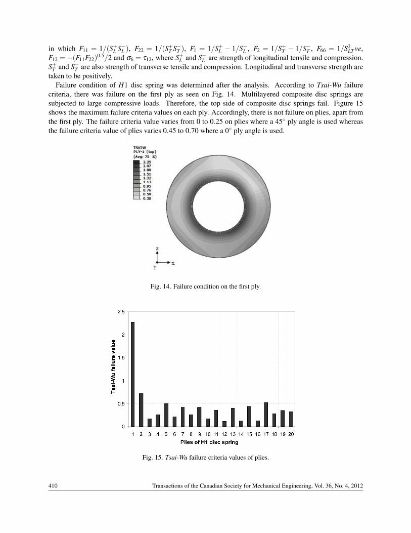
Failure condition of H1 disc spring was determined after the analysis. According to Tsai-Wu failurecriteria, there was failure on the first ply as seen on Fig. 14. Multilayered composite disc springs aresubjected to large compressive loads. Therefore, the top side of composite disc springs fail. Figure 15shows the maximum failure criteria values on each ply. Accordingly, there is not failure on plies, apart fromthe first ply. The failure criteria value varies from 0 to 0.25 on plies where a 45◦ ply angle is used whereasthe failure criteria value of plies varies 0.45 to 0.70 where a 0◦ ply angle is used.
Fig. 14. Failure condition on the first ply.
Fig. 15. Tsai-Wu failure criteria values of plies.
410 Transactions of the Canadian Society for Mechanical Engineering, Vol. 36, No. 4, 2012
4. CONCLUSIONS
Basically, the study examined disc springs with different section geometry and hybrid composite discsprings with finite elements method. Initially, it was determined whether or not analytical study and exper-imental study were compatible with the study conducted with finite elements method. Then disc springswith different cross-section were modeled and the disc spring having the lowest mass-highest load capacitywas determined. Finally, standard section hybrid disc springs made up of carbon/epoxy and glass/epoxyplies were modeled and these disc springs were evaluated in terms of load capacity and costs. Then failurecondition of optimum disc spring was determined.
The results of the studies conducted can be listed as follows:
• Disc modeled with finite elements method is in conformity with both analytical and experimentalstudies, if we taken into consideration load-deflection curve.
• Trapeze A section disc spring, a different section disc spring, has advantages in term of load capac-ity and mass, in comparison to standard section disc springs and certain other different section discsprings.
• Hybrid disc springs made with symmetric lamination offer advantages in terms of maximum loadcapacity and cost.
• Selecting a material that is more rigid (carbon/epoxy for outer plies of hybrid disc springs offers loadcapacity and cost advantages. The cost of disc spring increases directly as the increased number ofcarbon plies in the outside plies and the marginal advantage in terms of load capacity decreases.
• In case of composite disc springs, ply on the surface, where compression force is applied, is damaged.The disc spring top side subjected to force should be some other material in order to prevent suchcrushing damage.
REFERENCES
1. Mahmood, M. S. and Davood, R., “Analysis and optimization of a composite leaf spring”, Composite Structures,Vol. 60, No. 3, pp. 317–325, 2003.
2. Al-Qureshi, H. A., “Automobile springs from composite materials”, Journal Of Materials Prosessing Technol-ogy, Vol. 118, Nos. 1–3, pp. 58–61, 2001.
3. Mahdi, E, Alkoles, O. M. S., Hamauda, A. M. S., Sahari, B. B., Yonus, R. and Goudah, G., “Light compositeelliptic springs for vehicle suspension”, Composite Structures, Vol. 75, Nos. 1–4, pp. 24–28, 2006.
4. Chang, J., “Method of manufacturing hybrid composite leaf spring”, US Patent, Patent number: 5,425,829, 1995.5. Chang, H.C., Chung, L. H., Han, S.T. and Wei, P. L., “An experimental investigation into the mechanical behav-
iors of helical composite springs”, Composite Structures, Vol. 77, No. 3, pp. 331–340, 2007.6. Sancaktar, E. and Gowrishangar, S., Durability of Analysis of Composite Systems, Swets & Zellinger Lisse,
ISBN 90 5809 3824, 2002.7. Sancaktar, E. and Gowrishangar S., “Fiber reinforced composite springs”, US Patent Application Publication,
No. US 2004/0195744-A1, 2004.8. Almen, J. O. and Laszlo, A., “The uniform-section disc spring”, Transactions of the ASME, Vol. 58, pp. 305–14,
1936.9. Dharan, C. K .H. and Bauman J. A., “Composite disc springs”, Composites: Part A, Vol. 38, No. 12,
pp. 2511–2516, 2007.10. Pedersen, N. L. and Pedersen, P., “Stiffness and design for strength of trapezoidal Belleville springs”, Journal of
Strain Analysis for Engineering Design, Vol. 46, No. 8, pp. 825–836, 2011.11. Greenwood, J. H. and Robichek, E., Reinforced Disk Springs, US Patent No. 4,027,865, 1975.12. Schnorr Corporation, Handbook For Disc Spring, Ann Arbor, Michigan, USA, 2003.
Transactions of the Canadian Society for Mechanical Engineering, Vol. 36, No. 4, 2012 411
13. Gay, D., Hoa, S.V. and Tsai, S.W., Composite Materials CRC Press, Washington D.C., USA, 2002.14. Okutan, B., Aslan, Z. and Karakuzu, R., “A study of the effects of various geometric parameters on the fail-
ure strength of pin-loaded woven-glass-fiber reinforced epoxy laminate”, Composites Science and Technology,Vol. 61, No. 10, pp. 1491–1497, 2001.
15. Gerngroß, T., “Folding of Thin-walled Composite Structures”, Technical report No. TUM-MW 65/0331-SA,University of Cambridge, England, UK, 2003.
16. Karakaya, S. and Soykasap, Ö., “Natural frequency and buckling optimization of laminated hybrid compositeplates using genetic algorithm and simulated annealing,” Structural and Multidisciplinary Optimization, Vol. 43,No. 1, pp. 61–72, 2011.
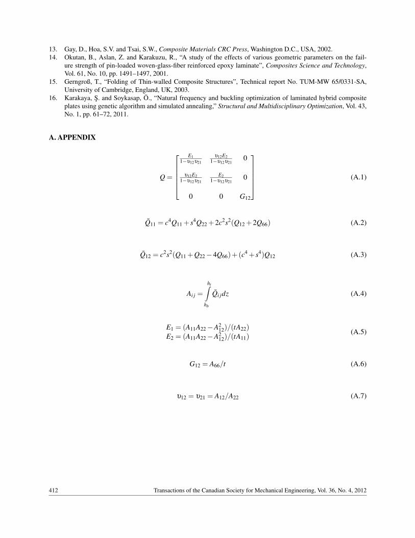
A. APPENDIX
Q =
E1
1−υ12υ21
υ12E21−υ12υ21
0
υ12E21−υ12υ21
E21−υ12υ21
0
0 0 G12
(A.1)
Q11 = c4Q11 + s4Q22 +2c2s2(Q12 +2Q66) (A.2)
Q12 = c2s2(Q11 +Q22 −4Q66)+(c4 + s4)Q12 (A.3)
Ai j =
ht∫hb
Qi jdz (A.4)
E1 = (A11A22 −A212)/(tA22)
E2 = (A11A22 −A212)/(tA11)
(A.5)
G12 = A66/t (A.6)
υ12 = υ21 = A12/A22 (A.7)
412 Transactions of the Canadian Society for Mechanical Engineering, Vol. 36, No. 4, 2012


