Embed Size (px)
Citation preview

Spring Contact Test ProbesBench-top Test Jigs
Specialist Test Products
Coda Systems LtdOak Road, Little Maplestead, Halstead, Essex, CO9 2RT UK
+44 (0)1787 478678 • Fax: +44 (0)1787 274194 [email protected]
Coda Systems LtdOak Road, Little Maplestead, Halstead, Essex, CO9 2RT UK
+44 (0)1787 478678 • Fax: +44 (0)1787 274194 [email protected]
www.coda-systems.co.uk
Kelvin Test Probes
Micro Test Probes
ATE Test Probes
General PurposeTest Probes
Kelvin Test Pinsand Fixture Kits
Bench-topTest Jigs
High CurrentTest Probes
Contents
What is a Spring Contact Test Probe?
Welcome to the largest ever Coda-Pin Test Product Catalogue.
For the first time we have combined our extensive range of test probes, bench-toptest jigs and many other specialist test products into one catalogue.
If you can’t find the test probe or product you require please contact us; we may beable to source something for you.
+44 (0)1787 478678
General PurposeTest Probes,Receptacles & Tools
ATE Test Probes,Receptaclesand Tools
Bench-top Test Jigsand Accessories
Specialist TestProducts
• High current test probes 22, 23• Ultra-high current test probes 24• Kelvin test probes 25• Kelvin test pins and fixture kits 26, 27• High frequency test probes 28• Switching test probes 29• Pneumatically controlled probing systems 30, 31• Micro test probes 32, 33• Presence detection switch probes 34• Bladed test probes 35• Large headed test probes 35• Test jig parts 36, 37
Press ringTermination solder cup Roll crimp Barrel Plunger Contact tip style
Receptacle Test Probe
Test probes - test pins - spring probes - pogo pins; these are all generic terms to describe a component whose spring loaded tip willprovide a reliable electrical contact to a target whose distance away may well be indeterminate. The traditional use for them is tomake contact with printed circuit boards (PCBs) or electrical components, in order to test functionality and to measure the value ofthe components. They are widely used in vacuum test fixtures associated with automatic test equipment (ATE). They are also usedinside a functional test station as part of a larger production line.
The test probe is comprised of a metal tube, ready assembled with a spring and contact plunger, supplied as a one-piece item.They are usually gold plated as gold is an excellent electrical conductor and is resistant to corrosion. The electrical cable isgenerally connected to a receptacle which the test probe inserts into. The use of a receptacle allows the test probe to be removedfor cleaning or replacement without having to dissconnect the electrical cable (see illustration below).
The illustration opposite shows a test probe and itsreceptacle mounted in a block with the electricalconnection made to the tail of the receptacle. Thereceptacle has been inserted using a receptacleinsertion tool. Finally the cable is soldered to thetermination and the probe installed.
PA1 4
General Purpose Test Probes
ATE Test Probes
High Current Test Probes
PA2 4
PA3 & HD-PA3 5
PC6 5
PC8 5
PA4 6
PA5 7
PA6 7
PA7 7
ELPA2 8
LPA4 8
ELPA4 8
LPA5 8
LPA7 8
PA4 & ST-PA4 12
LF-PA4 12
LF-LPA2 13
LPA2 & ST-LPA2 13
LPC1 & ST-LPC1 14
LF-LPC1 14
HD-PC8 23
HD-PA4 22
HD-PA5 22
HD-PA6 23
HD-PA7 23
Probe identification guideAll shown actual size
Page
Page
Page
For quotations, availability or to place an order -
www.coda-systems.co.uk
Page• i How to use 2, 3• Short Reach 4, 5• Medium Reach 6, 7• Long Reach 8
• i How to use 10, 11• 2.54mm/0.1” centre spacing 12• 1.91mm/0.075” centre spacing 13• 1.27mm/0.050” centre spacing 14• Presence detection and ATE travel indicator probes 14• ATE test probes and receptacle tools 15
• MF Series 17• CMF Series 18• CGF Series 19• i How to fit test probes and receptacles into abench-top test jig 20

Page4, 5
Page2, 3
Page6, 7
Page8
Short Reach
Medium Reach
Long Reach
• Product selection• Fitment and usage• Aftercare
• Low profile, short travel test probes for restrictedspace applications
• Applications where long travel is not required,such as for testing thin film/hybrid circuits orbareboard PCBs
• For use in bench-top test jigs• Replaceable test probe by use of a receptacle• Other applications such as device programming,
as an interface between two stages or for use asa compliant contact in your product
• Industry standard height for test jigs, fixtures andproduction line test positions
• Wide range of widths available depending on thetest centre spacing (pitch)
• General purpose testing of components,transformers, connectors and sub-assemblies
• Replaceable test probe by use of a receptacle
• Recessed test targets• Dual-height test fixtures• Component leads whose height may vary• Replaceable test probe by use of a receptacle
General PurposeTest Probes
1
i Information
For samples, quotations, availability or to place an order:www.coda-systems.co.uk [email protected]
+44 (0)1787 478678
For technical advice: [email protected]
+44 (0)1787 478678

Product selection
Probe tip selection
• Clean leads, pins
• Clean terminalpins
• Connectortesting
• PCB lands
• PCB pads
Concave
Spear or Point
Tip style Application Tip style Application Tip style Application Tip style Application
• PCB gold edgefingers
• Connectortesting
• Leaves nowitness marks
Radius
• Clean componentpins
• Flat PCB pads
• Leaves no witnessmarks
• Bead probingapplications
Flat
• Clean platedthrough holes
• Connector sockets
• Clean PCB pads
Convex
• Solder connection for cables• Suitable for low density arrays• Multi-strand cablerecommended
• Solderless connection• Crimp tool required
• Wireless connection• Low resistance
• Solderless connection• Quick release
PCB
• For slightlycontaminatedleads, pins andblades
• Male connectorpins
• High currentapplications
• Large headedtypes for ill-defined targets
Serrated
• PCB platedthrough holes
• Connector testapplications
• Self-cleaning tipstyle
Pyramid andStar Head
• Contaminated PCBleads and pads
• Self-cleaning tipstyle
• 8-pt crown forconnector pins
Crowns
Crimped
Solder-in
Connector plug-on
Solder-cup
• Contaminated orclean platedthrough holes
• PCB pads andlands
Sharp Pyramid
Once you have decided which series of general purpose test probe best suits your application, you will need to select a suitable tip style. The table below illustrateswhich of the tip styles is likely to be most effective in a particular situation.Most of our series have a choice of spring pressure. A lighter spring is preferred in test applications where the test point is considered clean or uncontaminated.The heavier spring will help the probe tip to penetrate better through any contamination. A lighter spring may have to be a consideration in test fixtures withlarge quantities of probes, or in situations where the density of probes is very high in a small area.
The receptacle is a type of socket that fits into the drilled hole in the probe plate or block. The test probe slips inside the receptacle allowing it to become areplaceable item as the electrical cable is connected to the tail of the receptacle. There are several versions of receptacle (see below) depending on your preferredchoice of cable termination - providing it is available in the specific probe series.
• Contaminatedplated throughholes
• PCB pads andlands
• Connectorapplications
Plain Star
• Contaminated viaholes
• Contaminated PCBpads and lands
Steel SuperSharp Blade
• Contaminated/varnished PCBs
• Uneven solderedsurfaces
• Bent or foldedover componentlands
Flexi-needle
How to use General Purp
Connector: RJ3-C and RJ4-C
Receptacle termination selectionTermination Application Termination Application
Wire-wrap • For high density arraysparticularly in ATE test fixtures
• Single or double wrap• Various lengths available• For solid core cable only
Round-pin • For connector plug-on• For use with multiwayconnectors
Round pin connector: RJ1-C
Solder-in
Solder-pot
• Wireless connection• Low resistance• Minimal extra length to theassembly
PCB
• Solder connection for cables• Suitable for low density arrays• Multi-strand cablerecommended
2
i Information
For samples, quotations, availability or to place an order:www.coda-systems.co.uk [email protected]
+44 (0)1787 478678
For technical advice: [email protected]
+44 (0)1787 478678

Fitment and usage
After care
A regular maintenance programme for your probes will help you achieve themaximum probe performance and lifespan. The necessary frequency andmethod of the maintenance/cleaning programme depends on your productionenvironment, the type of equipment and the probe series used.
Contamination left behind on the probe tip is the primary cause of probe contactproblems. This is often caused by a bi-product of the soldering process of eithersoldering flux or a solder residue. Other local contaminants such as dust, fluff,oil and grime can cause more temporary problems.
Light brushing of the probe tip with nylon, bristle or soft metal brushes willdislodge most contaminants.
Size Description Part no.108 x 64mm Brass/Bristle brush - soft BM01
108 x 64mm Nylon version - medium BM01N
83 x 29mm Brass brush 4 row - harsh BM02
159mm Nylon brush - soft BM03
BM03
BM01
BM01N
How to fit a receptacle into a drilled hole in a general purpose test position
Receptacle insertion tools Tungsten carbide drill bits
Receptacleseries
Testcentre
Mountingheight Part no. Drill hole size Part no.
RA1 1.27mm Flush TA1 0.90mm DA1
RA2 1.91mm Flush TA2 1.40mm DA2
LRA2 1.91mm Flush TA2 1.35mm 1.40mm DA2A DA2
RA3 2.54mm Flush TA3 1.70mm 1.75mm DA3A DA3
RA4 2.54mm Flush TA3 1.70mm 1.75mm DA3A DA3
PC6 2.54mm 0.127mm TA3 1.70mm DA3A
PC8 4.0mm 0.2mm TD2 3.0mm DS6
RA5 3.18mm Flush TA5 2.4mm DA5
RA6 4.75mm Flush TA6 2.75mm DA6
RA7 4.75mm Flush TA7 3.6mm DA7
pose Test Probes and Receptacles
3
Example fitment methods are shown for each series in the General Purpose TestProbe section starting overleaf. The receptacle is usually mounted into a probeplate. This plate can be made of resin-laminated fibreglass (types such as G10 orFR4), or plastic materials such as nylon, perspex or polycarbonate. The thicknessshould be such that it will support the total spring pressure of all probes without itbending significantly. For very large arrays of probes it may be necessary to putsome support pillars underneath to minimise this problem. For general purposetest applications, an 8-10mm thickness of material is recommended.
Carbide drills are best suited for drilling holes for receptacles in the hardercomposite or fibre based materials. Commonly available high-speed drills (HSS) aresuitable for plastics, such as peek, nylon or perspex. A few sizes of carbide drillshave an option of longer flute length for thicker probe plate materials. Note: Where two drilled hole sizes are shown, the larger hole is for harder materials such
as FR4, G10 and Tufnell, and the smaller hole is for plastics.
Notes: If you wish to use a probe without a receptacle, then these should be bonded into the probe plate. A correctly sized hole will be required. You may need to experiment with this.
3. Inserting the probeRemove the tool and insert the probe rearwards and
press home. The probe’s body isnormally fully enclosed withinthe receptacle.
4. Cable attachmentAttach the cable to the back endof the receptacle.
For samples, quotations, availability or to place an order:www.coda-systems.co.uk [email protected]
+44 (0)1787 478678
For technical advice: [email protected]
+44 (0)1787 478678
Probe plate8-10mmthickness
RA5S Raisedfitment 3mm
Flushfitment
Cable attached
TA5
1 2 43
1. Inserting the receptacleThe receptacle may be flushmounted or set raised slightlyabove the probe. In most generalpurpose test situations thereceptacle height is set to flush.
The receptacle should slip downunassisted until the press-ringrests against the probe plate.
2. Using a receptacle insertion toolReceptacle insertion tools are required for inserting the receptacle’s press-ring into thehole without damaging it (see table above for tool selection). This is particularilyimportant if you are using harder materials for the probe plate. Insert the pin of the
tool into the receptacle and tap the insertion tool gentlywith a hammer, until the receptacle is set to the desiredheight. See box 2a for instructions using epoxy fitment.
2a. Using epoxyIt is perfectly acceptable to use the press-ring asa shoulder to stop the receptacle from pushinginto the hole. However, you will have to bondthe receptacle in place using a suitable epoxy.We also offer receptacles with stop rings to allowflush mounting with epoxy.
RA5S
Using thepress-ring asa stop
Using thepress-ring ina recess
Using a stop-ringreceptacle
Epoxy Epoxy2a
RA5SF

CONCAVE HEAD
PLAIN CONCAVE
CONCAVE HEAD
L. SPRING H. SPRINGPA2AS PA2AX
SPEAR POINT
L. SPRING H. SPRINGPA2BS PA2BX
RADIUS HEAD
L. SPRING H. SPRINGPA2DS PA2DX
CONVEX HEAD
L. SPRING H. SPRINGPA2ES PA2EX
L. SPRING H. SPRINGPA1DS PA1DX
RADIUS HEAD
L. SPRING H. SPRINGPA1AS-021 PA1AX-021
L. SPRING H. SPRINGPA1AS PA1AX
0.89
0.89
0.53
REDUCED CONCAVE0.31
0.38
0.95
0.89
1.52
1.52
1.52
1.02
0.53
1.52
1.52
FLAT HEAD
L. SPRING H. SPRINGPA2FS PA2FX
1.52
1.52
SERRATED HEAD
L. SPRING H. SPRINGPA1HS PA1HX
0.89
0.89
PLAIN RADIUS
PLAIN CROWN
SPEAR POINT
PYRAMID HEAD
PYRAMID HEAD - LOWERPROFILE
SERRATED
L. SPRING H. SPRINGPA2HS PA2HX
CROWN HEAD
L. SPRING H. SPRINGPA2QS PA2QX
PYRAMID HEAD
L. SPRING H. SPRINGPA2TS PA2TX
L. SPRING H. SPRINGPA1TS PA1TX
Reduced travel version1.27mm travel
SPA1TS OAL = 14.99mmSpring force 3 oz
CRIMP
RA1CRA1C-W450 pre-wired with 760mm kynar (30 awg)
WIRE-WRAP
SOLDER-CUP
RA2S
CRIMP
RA2C
L. SPRING H. SPRINGPA1BS PA1BX
L. SPRING H. SPRINGPA1QS-021 PA1QX-021
L. SPRING H. SPRINGPA1JS PA1JX
0.53
0.53
0.53
0.89
0.89
1.02
0.89
17.53
.86 typical.56 typical .68 typical
4.57
2.67
0.94
Press ring
4.06Typical1.32
Typical.89
Typical
17.534.57
1.47
Ø 0.64
27.3
P
Press ring
4.06Typical1.32
Typical
4.57
1.47RA2R
RA2R-1.0
1.52
1.45
1.07
Self-Cleaning
1.52
0.53
1.52
1.52
Mounting hole size: 0.89/0.93mm0.90mm drill is most commonly used: Drill part no. DA1RIT tool part no. TA1
General Purpose Test Probes -Example installations
RA1S
PA1AS P3.43mm
RA1SF
PA1HS3.8mm
EpoxyRA2S
PA2ES4.06mm
Flush fittingreceptacle usingpress-ring
Flush fittingreceptacleusing press-ring
Flush fittingreceptacleusing stop-ring
Receptacles
Mounting hole size: 1.35/1.40mm1.4mm drill is most commonly used:Drill part no. DA2RIT tool part no. TA2
Receptacles
PA1 Series A short reach, general purpose test probe for 1.27mm test centres A short reach, general purpose test probe for 1.91mm test centres
Specification
Tip styles
Full travel 2.54mmWorking travel 1.70mmSpring force initial at wkg travel(S) Light spring 17g 79g(X) Heavy spring 22g 105g
Current rating DC cont (max) 3 AmpsMinimum test centres 1.27mm
16.130.66
3.43
Full Travel2.54
Actual size
Tip styles
Full travel 2.54mmWorking travel 1.70mmSpring force initial at wkg travel(S) Light spring 32g 71g(X) Heavy spring 37g 128g
Current rating DC cont (max) 3 AmpsMinimum test centres 1.91mm
16.64
4.061.02
Full Travel2.54
0.85
18.0
0.9512.0
0.2
SOLDER-CUP - press-ring
RA1R
RA2W
30.23
0.64
Press ring
4.06Typical1.32
Typical
4.57
1.47
Actual size
18.00.960.65 0.85
13.0
0.4
23.4
Flush fitment with press-ring
ShortReach
• Low profile, short travel test probes for restricted space applications• Applications where long travel is not required, such as thin
film/hybrid circuits or bareboard PCB testing• For use in bench-top test jigs• Replaceable test probe by use of a receptacle
4
CROWN HEAD
L. SPRING H. SPRINGPA1QS PA1QX
0.89
0.89
Self-Cleaning
PA2 Series
RA1SF Note: Probe barrel protrudes slightlyL. SPRING H. SPRINGPA2JS PA2JX
RA1S
For samples, quotations, availability or to place an order:www.coda-systems.co.uk [email protected]
+44 (0)1787 478678
For technical advice: [email protected]
+44 (0)1787 478678
Specification
L. SPRING H. SPRINGPA1AS-012 PA1AX-012
0.64mm ROUND-PIN
Ø 1.0
26.45Press ring
4.06Typical1.32
Typical
4.57
1.47
P
1mm ROUND-PIN
17.53
.86 typical.68 typical
4.57
2.67
0.94
ROUND-PIN
Flush fitment with stop-ring
SOLDER-CUP - stop-ring
PLAIN RADIUS
4.06Typical1.32
Typical1.12
Typical.89
Typical
17.534.57 Press ring
1.47

SPEAR POINT
L. SPRING PC6BS
L. SPRING PC6HS-1.1 H. SPRING PC6HX-1.1
H. SPRING PC6BX
1.37
9.78
1.14
2.5
PLAIN SERRATED - 1mm
1.37
10.1
1.14 2.9
1.37
10.2 1.91.5
3.04
L. SPRING PC6HS-2.0 H. SPRING PC6HX-2.0
SERRATED HEAD - 2mm
PLAIN RADIUS
L. SPRING PC6JS H. SPRING PC6JX
RC6S-G
SOLDER-CUP
1.65
10.75
3.30 1.75
1.92
1.37
9.47
1.14
2.2
CONVEX HEADL. SPRING H. SPRINGPA3ES PA3EX
FLAT HEADL. SPRING H. SPRINGPA3FS PA3FX
2.03
1.90
2.03
1.90
PLAIN RADIUS
SERRATEDHEADS
1.04
L. SPRING H. SPRINGPA3JS PA3JX Other tip diameters available
Tip Diam.
MULTI-POINT CROWNS
CROWN HEAD 1.3mm
SMALL CROWN
L. SPRING H. SPRINGPA3QS PA3QX
L. SPRING H. SPRINGPA3QPS PA3QPX
CRIMP - plug-on
RA3C Plug-on connector for tail: RJ3-C Shrink sleeve HSS3
TIP Diam. L. SPRING1.9mm PA3HS2.5mm PA3HS-2.5*
3.5mm PA3HS-3.5*
TIP Diam. H. SPRING1.9mm PA3HX2.5mm PA3HX-2.5*
3.5mm PA3HX-3.5*
0.64
1.22Typical
3.1723.62
1.47 Typical 1.68 6.09
SOLDER-CUP - press-ring
RA3S
Press ring1.781.22
Typical
3.1724.1
1.47 Typical 1.68 6.09
1.68
1.22Typical
5.023.5
2.0
2.03
1.52 1.27Self-cleaning
RADIUS HEAD - 2.3mm
FLAT HEAD - 2.3mm
SERRATED HEAD -2.3mm
SERRATED HEAD -3.5mm
PC8FS-090
PC8HS-090
PC8HS-138
1.60
2.30
2.3
1.6
FLAT HEAD - 3.5mm
PC8FS-138
3.5
1.6
2.30
3.5
L. SPRING 80g PC8DLM. SPRING 150g PC8DSH. SPRING 250g PC8DX
*Not suitable for 2.5mm centres
Specification
Tip styles
Full travel 4.06mm
Working travel 2.69mm
Spring force initial at wkg travel
(S) Light spring 31g 99g
(X) Heavy spring 75g 184g
Current rating DC cont (max) 3 Amps
Minimum test centres 2.54mm
24.641.37
6.10
Full travel4.06
Actual size
Actual sizeA short reach, general purpose test probe for 2.54mm testcentres. See high current version page 22.
Tip styles
3.5
2.65
2.10
7.2
15.1
Actual size
A short reach, robust general purpose test probe for 4mmtest centres. See high current version page 23.
Specification
Tip styles
Full travel 1.27mmWorking travel 0.84mmSpring force at full travel (S) Light 110g
(X) Heavy 200gCurrent rating DC cont (max) 3 AmpsMinimum centre spacing 2.54mm
A short reach,general purpose
test probe for 2.54mm test centres
CONCAVE HEAD
L. SPRING H. SPRINGPA3AS PA3AX
SPEAR POINTL. SPRING H. SPRINGPA3BS PA3BX
PLAIN FLATL. SPRING H. SPRINGPA3CS PA3CX
RADIUS HEAD
L. SPRING H. SPRINGPA3DS PA3DX
2.03
1.90
1.04
1.04
2.03
1.27
REDUCED RADIUS - 0.76mm
L. SPRING H. SPRINGPA3JS-064 PA3JX-064
0.761.02
3.3
FLEXI-NEEDLE
H. SPRINGPA3PX
0.38
Mounting hole size: 1.7/1.75mm1.75mm drill is most commonly used: Drill part no. DA3RIT tool part no. TA3, TA4A
Receptacles
Receptacles
Receptacles
0.64mm ROUND-PIN
RA3R
SOLDER-IN
33.53
3.1723.62
1.68 Typical 6.09
1.0mm ROUND-PIN
RA3R-1.0We suggest use of 1mm Ø connectors such as RJ1-C (unwired plug).
33.0
3.1723.62
1.68 Typical 6.09
18.67 1.78
1.68 Typical 6.09RA3P
Mounting hole size: 3.0mmDrill part no. DS6
RC8S
SOLDER-POT - press-fitment
Back drilled
Ø 3.3
13.6
3.0
0.2
2.08
Mounting hole size: 1.70mm1.70mm drill is most commonly used: Drill part no. DA3RIT tool part no. TA3
Example installationsExample installations
RC6S-G
PC6HS-2.0 3.04mm
Flush fitmentwith stop-ring
Example installation
RC8S
7.2mmPC8DL
3.7mmFlush fitmentwith stop-ring
PA3FS6.1mm
6.1mm
2mm
RA3S
PA3FS
RA3S
Receptacle raised Receptacleflush
SpecificationFull travel 3.5mmWorking travel 2.8mmSpring force at wkg travel 150gCurrent rating DC cont (max) 5 AmpsMinimum centres 4.0mmOther spring forces available - see under each tip style
General Purpose Test Probes -ShortReach
• Low profile, short travel test probes for restricted space applications• Applications where long travel is not required, such as thin
film/hybrid circuits or bareboard PCB testing• For use in bench-top test jigs• Replaceable test probe by use of a receptacle
STAR HEAD
L. SPRING H. SPRINGPA3TS PA3TX
L. SPRING H. SPRINGPA3MS PA3MX
PYRAMID HEAD
1.91
Self-cleaning
2.03
1.90
RADIUS HEAD
L. SPRING PC6DS H. SPRING PC6DX
9.47
1.96
1.37
2.2
5
PC6 Series
PC8 Series
PA3 Series
RA3W
SOLDER-CUP - stop-ring
For samples, quotations, availability or to place an order:www.coda-systems.co.uk [email protected]
+44 (0)1787 478678
For technical advice: [email protected]
+44 (0)1787 478678
WIRE-WRAP
0.64
36.833.17
23.62
1.68 Typical 6.09
RA3SF Hole size 1.70mm

PA4ASPA4AXPA4AU
PA4FSPA4FX
2.0
1.50
SPEAR POINT FLAT HEAD - 1.5mm
PA4BSPA4BXPA4BU
0.87
SERRATED HEAD - 1.5mm
PA4HSPA4HXPA4HU
2.02
1.52
L. SPRINGH. SPRINGU.H. SPRING
L. SPRINGH. SPRINGU.H. SPRING
L. SPRINGH. SPRINGU.H. SPRING
L. SPRINGH. SPRING
Current 8 amps max
X = 1.5mm Ø
Current 8 amps max Current 3 amps max
Current 8 amps max
PA4DSPA4DX
DOME HEAD
1.3
L. SPRINGH. SPRING
PA4AS-2.0PA4AX-2.0
90°
X
2.03
L. SPRINGH. SPRING
CONCAVE HEAD -1.5 & 2mm
Current 3 amps maxCurrent 3 amps max
1.3mm CROWNSelf-cleaning
PA4QS-050PA4QX-050PA4QU-050
2.03
1.27
1.5mm CROWNSelf-cleaning
PA4QS-060PA4QX-060
2.03
1.52
PA4TS-041PA4TX-041PA4TU-041
SHARP PYRAMID
0.86
L. SPRINGH. SPRINGU.H. SPRING
L. SPRINGH. SPRINGU.H. SPRING
L. SPRINGH. SPRING
Current 8 amps max
Current 8 amps max
Current 3 amps max
2.0mm CROWN HEADSelf-cleaning
PA4QS-080PA4QX-080
2.03
2.0L. SPRINGH. SPRING
Current 3 amps max
8-POINT CROWNHEAD - 1.5mmSelf-cleaning
PA4ZSPA4ZXPA4ZU
2.03
1.52L. SPRINGH. SPRINGU.H. SPRING
Current 8 amps max Smaller diameter head available
Diameter1.5mm1.5mm2.0mm2.0mm2.5mm3.5mm
PYRAMID HEADS
L. SPRINGH. SPRINGL. SPRINGH. SPRINGH. SPRINGH. SPRING
PA4TSPA4TXPA4TS-2.0PA4TX-2.0PA4TX-2.5*PA4TX-3.5*
CRIMP - plug-on
RA4CPlug-on connector for tail: RJ3-C RA4S
29.214.571.22
typical
1.47 typical 1.68 typical 7.62 typical
1.83
30.234.57
1.47 typical 1.68 typical 7.62typical
1.83Press ring1.22
typicalRA4WSee ATE probe section for alternative versions (page 12)
0.64
39.9 typical4.57
1.47 typical 1.68 typical 7.62 typical
Current 3 amps max *Not suitable for 2.5mm centres
1.00
PA4JSPA4JX
L. SPRINGH. SPRING
Current 3 amps max
0.5mm SMALL CROWNSelf-cleaning
PA4QS-018PA4QX-018PA4QU-018
3.81
0.45L. SPRINGH. SPRINGU.H. SPRING
PA4CSPA4CX
PLAIN FLAT
0.86
L. SPRINGH. SPRING
Current 8 ampsmax
Current 8 amps max
Tip styles
Tip styles (continued)
Full travel 6.35mmWorking travel 4.24mmSpring force at wkg travel(S) Light spring 114g(X) Heavy spring 170g(U) Ultra heavy spring 283g
Current rating DC cont (max) shown under each tip styleMinimum test centres 2.54mm
33.02 typical8.38
Max. travel 6.351.37
Actual size
A medium reach, general purpose test probe for testing at aminimum of 2.54mm centres. See high current version page 22.
8.5mm 8.4mm 11.4mm 3mm7.6mm
RA4SF RA4S RA4S RA4S
PA4AS
Epoxy
Press fitment - epoxy fitment preferable Press fitment - using insertion tool Using press ring as collar. Epoxy fitment
CollarFlushfitment
Raisedfitment
Epoxy
16.0mm
Example installations
PA4QPS-040PA4QPX-040PA4QPU-040
0.9mm PLAIN CROWNSelf-cleaning
0.87
L. SPRINGH. SPRINGU.H. SPRING
Current 8 amps max
General Purpose Test Probes -MediumReach
LARGER SERRATEDHEADS
2.0mm2.5mm3.0mm4.0mm
L. SPRING H. SPRINGA diam.
PA4HS-080PA4HS-100*PA4HS-120*PA4HS-160*
PA4HX-080PA4HX-100*PA4HX-120*PA4HX-160*
2.0
A Diam
Current 3 amps max *Not suitable for 2.5mm centres
PLAIN RADIUS
• Industry standard height for test jigs and production line test positions• Wide range of widths depending on the test centre spacing (pitch)• General purpose testing of components, transformers, connectors and
sub-assemblies• Replaceable test probe by use of a receptacle
SOLDER-CUP - press-ring
RA4S12
1.67
4.52.0
29.05
1.0
SOLDER-CUP - stop collar
RA4SF Hole size 1.70mm
PA4 Series
6
For samples, quotations, availability or to place an order:www.coda-systems.co.uk [email protected]
+44 (0)1787 478678
For technical advice: [email protected]
+44 (0)1787 478678
Specification
X = 2.0mm Ø
Mounting hole size: 1.7/1.75mm 1.75mm drill is most commonly used: Drill part no. DA3, RIT tool part no. TA3, TA4A
Receptacles
WIRE-WRAP
Press ring
1.851.67
30.0
12.0
SOLDER-CUP - press-ringSOLDER-IN18.67
1.68 typical 7.62typical
1.83Press ring
RA4P

Receptacle
Probe
Example installation for PA5,6,7
SPEAR POINT
L. SPRING H. SPRINGPA6BS PA6BX
CONCAVE HEAD
L. SPRING H. SPRINGPA6AS PA6AX
PLAIN FLAT
L. SPRING H. SPRINGPA6CS PA6CX
90°2.54
3.96
1.52
1.52
CRIMP - plug-on
RA6C connector: RJ6-C Shrink sleeve: HSS6
CRIMP - plug-on
RA7C connector: RJ6-C
SOLDER-CUP
RA7S
WIRE-WRAP
RA7W
SOLDER-CUP
RA6S
WIRE-WRAP
30.484.57
7.62Typical
2.06Typical
2.34 Typical2.69 Typical
2.82
Press ring 2.8230.48
4.57
7.62Typical
2.34 Typical 2.69 Typical
40.9
0.64
30.48
4.57
7.62Typical
2.34 Typical 2.69 Typical
2.82
33.534.57
2.01Typical 3.56 Typical 7.62
Typical
2.36Typical
3.66
Press Ring 3.66
3.56 Typical2.36 Typical2.01 Typical
4.57
7.62Typical
33.53
44.00
0.643.66
3.56 Typical2.36 Typical
4.57
7.62Typical
33.53
Mounting hole size: 2.72/2.77mm2.75mm drill is most commonly used: Drill part no. DA6RIT tool part no. TA6
Receptacles
Mounting hole size: 3.58/3.63mm3.6mm drill is most commonly used: Drill part no. DA7RIT tool part no. TA7
Receptacles
CRIMP - plug-on
RA5C connector: RJ3-C Shrink sleeve HSS3
SOLDER-IN
RA5P
24.76
7.62Typical2.36 Typical
2.49
1mm ROUND-PIN
RA5R-040
1.00
39.80
30.48
1.47 Typical 2.36 Typical 7.62 Typ.
4.57
Press ring2.4930.48
1.19Typical
1.47 Typical 2.36 Typical 7.62 Typ.
4.57
30.48
1.19Typical 1.47
Typical2.36
Typical7.62
Typical
4.57 2.49
We suggest use of 1mm Ø connectors such as RJ1-C
Tip styles
Tip stylesFull travel 6.35mmWorking travel 4.24mmSpring force initial at wkg travel(S) Light spring 63g 136g(X) Heavy spring 91g 195g
Current rating DC cont (max) 7 AmpsMinimum test centres 4.75mm
33.53
2.36
8.89
Full travel 6.35
Actual size
A medium reach, general purpose test probe for testing at aminimum of 4.75mm centres
Full travel 6.35mmWorking travel 4.24mmSpring force initial at wkg travel
173g 454gexcept PA7JL 50g 213gCurrent rating DC cont (max) 8 AmpsMinimum test centres 4.75mm
36.073.18
8.89
Full travel 6.35
Actual size
A medium reach, general purpose test probe with a high springforce for testing at a minimum of 4.75mm centres
SPEAR POINT
2.03
CONVEXHEAD
3.96
2.54
SERRATEDHEAD
3.96
2.54
PLAIN RADIUS
L. SPRING H. SPRINGPA7JL PA7JS
H. SPRINGPA7BS
H. SPRINGPA7ES
H. SPRINGPA7HS
2.03
H. SPRINGPA7QS-050 steel
SMALL CROWN- 1.3mm
1.75
1.3
PLAIN RADIUS
L. SPRING H. SPRINGPA6JS PA6JX
1.52
SERRATEDHEAD -2.5mm
2.03
2.54
PA5HSPA5HX
L. SPRINGH. SPRING
FLAT HEAD
PA5FSPA5FX
L. SPRINGH. SPRING
CONVEX HEAD2.03
2.54
90°
PA5ESPA5EX
L. SPRINGH. SPRING
RADIUS HEAD2.03
1.58 PA5DSPA5DX
L. SPRINGH. SPRING
SPEAR POINT
30°1.27
PA5BSPA5BX
L. SPRINGH. SPRING
CONCAVE HEAD2.03
2.54
PA5ASPA5AX
L. SPRINGH. SPRING
SpecificationFull travel 6.35mmWorking travel 4.24mmSpring force initial at wkg travel(S) Light spring 45g 130g(X) Heavy spring 71g 180g
Current rating DC cont (max) 6 AmpsMinimum test centres 3.2mm
33.02
2.03
8.38
Full travel 6.35
Actual size
A medium reach,general purposeprobe for testing
at a minimum of 3.2mm centres
PLAIN FLAT1.27
PA5CSPA5CX
L. SPRINGH. SPRING
STEEL SPEAR(LONGER)
1.7
11.33
ST-PA5BXLH. SPRING Full travel = 6.35mm
CROWN HEAD- 3mm
H. SPRINGPA7QS-120
3.0
2.5
RADIUS HEAD
L. SPRING H. SPRINGPA6DS PA6DX
2.54
2.36
L. SPRING H. SPRINGPA6ES PA6EX
2.54
3.96
90°
PLAIN CROWN
L. SPRING H. SPRINGPA6QPS PA6QPX
Self-cleaning
1.52 dia
2.62.52.0
CONVEX HEAD
L. SPRING H. SPRINGPA6FS PA6FX
2.54
3.96
FLAT HEAD
SERRATEDHEAD -3.9mm(not suitable for3.2mmcentres)
1.52
3.9
PA5HS-3.9PA5HX-3.9
L. SPRINGH. SPRING
PLAIN RADIUS1.27
PA5JSPA5JX
L. SPRINGH. SPRING
CROWN HEAD
2.54
PA5QSPA5QX
L. SPRINGH. SPRING
PLAINCROWN
Self-cleaning
1.27 DIA
PA5QPSL. SPRING
PYRAMIDHEAD
2.54
2.5
PA5TSPA5TX
L. SPRINGH. SPRING
RA5S
2.54
2.54
Tip styles
ReceptaclesMounting hole size: 2.39/2.44mm 2.4mm drill is most commonly used: Drill part no. DA5 RIT tool part no. TA5
RA6W
SOLDER-CUP - press-ring
General Purpose Test Probes -MediumReach
• Industry standard height for test jigs and production line test positions• Wide range of widths depending on the test centre spacing (pitch)• General purpose testing of components, transformers, connectors and
sub-assemblies• Replaceable test probe by use of a receptacle• See high current versions on pages 22 and 23
SERRATEDHEAD
L. SPRING H. SPRINGPA6HS PA6HX
2.54
3.96
SOLDER-IN
RA6P
24.76
7.62Typical2.69 Typical
2.82
PLAIN STAR- 2.75mm
H. SPRINGST-PA7MS steel
60°
2.75
7
PA5 Series
PA6 Series PA7 Series
WIRE-WRAP
2.43
2.79
32.8
1.78 2.48 0.5
1.20
RA5SF
0.64
39.88
30.48
1.47 Typical 2.36 Typical7.62
Typical
4.57 2.49
RA5W
3.96
2.54
H. SPRINGPA7AS
L. SPRING H. SPRINGPA6TS PA6TX
For samples, quotations, availability or to place an order:www.coda-systems.co.uk [email protected]
+44 (0)1787 478678
For technical advice: [email protected]
+44 (0)1787 478678
SpecificationSpecification
Drill hole size: Epoxy 2.5mm, Interference 2.45mm
SOLDER-POT - stop-ring
PYRAMID HEAD
CONCAVEHEAD
Tip styles

11.4mm3mm
LRA2
14.3mm
LRA2 RA4
15.45mm 17.0mm
RA4 RA4
24.0mm
RA4S12
10.0mm
15.3mm
RA5
15.6mm
RA7 RA5S
PA5HS
RA5S
LPA5HS
Long reach probeworking into arecessed area showingcompression
Componentunder test
3mm 3mm 3mm 3mm 3mm 3mm
LPA2ASELPA2HS PA4AS
LPA4ASELPA4HS ELPA4HS
LPA5HSLPA7AS
3mm
11.4mm
SERRATED HEAD
LPA4HS ELPA4HX
1.5
PYRAMID HEAD 1.5
LPA4TS ELPA4TX
CROWN HEAD
LPA4QS-060 ELPA4QX-060
LPA4QS-060 1.3mmELPA4QX-060 1.5mm
PLAIN CROWNSelf-cleaning
ELPA2QPS
SUPER SHARP BLADE
ELPA2KS
CROWN HEAD - 1.2mmSelf-cleaning
ELPA2QSELPA2HS
0.64
0.64 dia
0.991.191.19
2.02
ELPA2TS1.19
1.19
The ELPA2 series use the receptaclesof the LPA2 series - page 13
Specification
Tip styles
Full travel 10mmWorking travel 8mmSpring force at working travel 120gCurrent rating DC cont (max) 3 AmpsMinimum test centres 1.91mm
36.8
Full travel10.0
1.0 11.3
Actual size
LPA4 ELPA4Full travel 10.2mm 12.5mmWorking travel 8.0mm 9.6mmSpring force init/wkg trav init/wkg trav
26g / 227g 40g / 225gCurrent rating DC cont (max) 8 Amps 3 AmpsMinimum test centres 2.54mm 2.54mm
LPA4 37.1ELPA4 38.6
LPA4 12.45ELPA4 14.01.37
Actual size
Designed for use in dual-level fixturing where two differentsets of probes with different working travels are required in
the same test fixture. The long reach of this test probe also enables access to contactswhich are otherwise inaccessible with normal length probes. For 1.91mm centres.
Specification
Tip styles
LPA5 LPA7
Full travel 10.2mm 10.2mm
Working travel 8.0mm 8.0mm
Spring force init/wkg trav init/wkg trav
20g / 150g 80g / 400g
Current rating DC cont (max) 4 Amps 4 Amps
Minimum test centres 3.2mm 4.75mm
36.82.0 12.3
39.9
3.18 12.6
LPA5
LPA7
Actual size
Actual size
A longer reach version of PA5 and PA7, thisseries is ideal for functional test
applications where a point might be recessed or lower than the other points. For 3.2mmand 4.75mm centres.
Specification
Designed for use in dual-level fixturingwhere two different sets of probes with
different working travels are required in the same test fixture. The long reach solvesother problems of gaining access to contacts which are inaccessible with normal lengthprobes. Use the standard RA4 series receptacles (shown below). For 2.54mm centres.
CONCAVE HEAD
LPA5AS LPA7AS
SERRATED HEAD
LPA5HS LPA7HS
LPA5HS 2.5mmLPA7HS 4.0mm
Example installations showing heights
For LPA7
ReceptacleFor LPA5
Receptacles
LPA5QPS 1.3mm
Actual size
NEEDLE POINT
LPA4NS ELPA4NX
Steel
LPA4NS 0.64mmELPA4NS 0.60mm
SERRATED HEAD
PYRAMID HEAD -1.2mm
LPA5AS 2.5mmLPA7AS 4.0mm
RA7S
Press Ring 3.66
3.56 Typical2.36 Typical2.01 Typical
4.57
7.62Typical
33.53SOLDER-CUP
RA5S
Press ring2.4930.48
1.19Typical
1.47 Typical 2.36 Typical 7.62 Typ.
4.57
SOLDER-CUP
RA4C
SOLDER-CUP
RA4S
29.725.08
1.22Typical
1.47 Typical 1.68 Typical 7.62 Typical
29.725.08
1.47 Typical 1.68 Typical 7.62 Typical
1.83Press Ring1.22
Typical
RA4W
0.64
40.26
29.725.08
1.47 Typical 1.68 Typical 7.62 Typical
CRIMP
Hole size: 2.4mm Hole size: 3.6mm Hole size: 1.75mm
Hole size: 1.75mm
Hole size: 1.75mm
General Purpose Test Probes -LongReach
PLAIN CROWN
LPA4QS-040 ELPA4QX-040
LPA4QS-040 0.87mmELPA4QX-040 0.74mm
• Recessed test targets• Dual-height test fixtures• Component leads whose height may vary• Replaceable test probe by use of a receptacle
WIRE-WRAP
RA4S12 Hole size: 1.75mm
Press ring
1.851.67
30.0
12.0
ELPA2 Series LPA4 & ELPA4 Series
LPA5 & LPA7 Series
PLAIN CROWNSelf-cleaning
LPA5QPS
SPEAR POINT
ELPA4QX-041
LPA4KS ELPA4KX
LPA4JS ELPA4JX
LPA4AS ELPA4AX
8
For samples, quotations, availability or to place an order:www.coda-systems.co.uk [email protected]
+44 (0)1787 478678
For technical advice: [email protected]
+44 (0)1787 478678
Tip styles
CONCAVE HEAD
1.5
1.91
PLAIN RADIUS
1mm CROWN HEAD
1.0
LPA4KS 0.87mmELPA4KX 0.74mm
STEEL SUPER SHARP BLADE
LPA5BS LPA7BS
Receptacle
LPA5BS 1.3mmLPA7BS 2.0mm SOLDER-CUP
Receptacles

ATE Test ProbesTest probes for use in automatic test equipment with
vacuum, pneumatic or mechanically operated test fixtures
Page12
Page13
Page14
Page15
PA4, ST-PA4 Series33.02 typical
8.38
Max. travel 6.351.37
LPA2, ST-LPA2 Series33.02
1.02 Full travel 6.35
8.38
0.78 8.38
0.5043.18
LPC1, ST-LPC1 Series
PI Series
TIP Series
2.54mm/0.1”centres
1.91mm/0.075”centres
1.27mm/0.050”centres
ATE Test Probe & Receptacle Tools
Page10, 11
• Product selection• Fitment and usage• Aftercare
LF-PA4 Series
LF-LPA2 Series
LF-LPC1 Series
9
i Information
For samples, quotations, availability or to place an order:www.coda-systems.co.uk [email protected]
+44 (0)1787 478678
For technical advice: [email protected]
+44 (0)1787 478678
The universal size for use at1.27mm test centres in themajority of ATE test fixtures
The universal size for use at1.91mm test centres in themajority of ATE test fixtures
The universal size for use at2.54mm test centres in themajority of ATE test fixtures
Presence detection using aninsulating shroud
ATE travel indicator probes
ATE tools for the removal andinsertion of probes andreceptacles. Pass marking unit
33.02 typical8.38
Max. travel 6.351.37
33.02
1.02
6.86
Full travel 6.35
0.78 8.38
0.5043.18
How to use ATE TesProduct selection
The receptacle is a type of socket that fits into the drilled hole in the probe plate. Its use allows the probe to be a replaceable item for easy maintenance, withouthaving to disconnect the electrical cable. There are several versions of receptacle (see below) depending on your preferred choice of cable termination - providingit is available in the specific probe series.
• Clean leads, pins• Clean terminal pins
• PCB lands• PCB pads
Concave
Spear or Point
Tip style Application
• For slightly contaminated leads,pins and blades
• Male connector pins• Also available for lead-free solders
Serrated Head
• PCB plated through holes• Connector test applications• Self-cleaning
Pyramid andStar Head
Tip style Application Tip style Application
• For leads and connector pins• Eight radial pins ensure selfcleaning and good capture ofmisaligned leads and pins
• Self cleaning
8-Point Crown
• Gold edge fingers• Provides positive contact withoutleaving any marks or indentations
• Also used for some connectorapplications
Plain Radius
• For lands, pads and leads• High penetration of unclean testsurfaces
• Super sharp steel points staysharper for longer
• Self cleaning
Super Sharp3-needle
Steel CrossedBlade
• Lands and pads• Open tracks• Self cleaning
Probe tip selection
Termination Application
Crimp area
Crimp connector
• Solder connection for cables• Suitable for low density arrays• Multicore cable recommended
• Solder-less connection• Crimp tool required• Not vacuum tight
Termination Application
• Single or double wrap• For high density arrays particularly in ATEtest fixtures
• Various tail lengths available• Vacuum tight
• For plug-on connectors• For use with multiway connectors
Crimp connector
Solder-cup Wire-wrap tail
Round-pin tail
Crimp and Connector plug-on
Tulip • Tip for general purpose use• Six outer points with raised centrepoint
• Self-cleaning
Receptacle termination selection
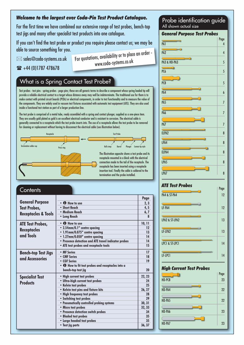
ATE probe tip selectionThere are three sizes of ATE test probes for the three standard test centrespacings (pitch) commonly used on printed circuit boards (PCBs). See previouspage. Once you have selected the probe size which will best suit your applicationyou will need to select suitable tip styles. The table below shows which of thetip styles is likely to be most effective for each particular test target.
Spring pressureMost series have a wide choice of spring pressure. A lighter spring is preferredin test applications where the test point is fairly clean or uncontaminated. Theheavier and extra heavy springs will help the probe tip to penetrate betterthrough any contamination. A lighter spring may have to be a consideration intest fixtures with large quantities of probes, or in situations where the densityof probes is very high in a small area.Be careful not to fit a probe spring force, which in total is more than the fixture
can handle, or may damage your PCBs top layer. It is better to target the extra-heavy spring forces in known problem areas.
Plunger material and lead-free solderThree choices of plunger and tip material are available depending on thevolume of the production run and the level of PCB contamination. See below:
10
Part numberprefix
Plunger and tipstylespecification
Uses
PA4, LPA2, LPC1 Standard material, beryliumcopper, gold plated
Low volume production, traditional solder, slightsurface contamination.
ST-PA4, ST-LPA2,ST-LPC1
Steel tipped plungers, goldplated
High volume production, for test targets whichcause tipstyle wear, higher surface contamination
from traditional or lead-free solders.
LF-PA4, LF-PA2,LF-LPC1
Up-rated, pre-loaded spring,hard wearing plated surface
High volume, surface contamination particular tomany lead-free solders.
i Information
For samples, quotations, availability or to place an order:www.coda-systems.co.uk [email protected]
+44 (0)1787 478678
For technical advice: [email protected]
+44 (0)1787 478678
Steel SuperSharp Blade
• Contaminated via holes• Contaminated pads and lands• Suitable for lead-free solder
Steel SuperSharp Dagger
• Contaminated via holes• Contaminated pads and lands• Suitable for lead-free solder
Steel 90°Blades
• Ideal for blind vias• Robust, hard wearing• Suitable for lead-free solder
Plain Pyramid
Sharp Pyramid • Plated-through holes and vias,which may be slightlycontaminated
• Suitable for lead-free solder
Crowns • Contaminated PCB leads and pads• Self-cleaning• Also available for lead-freesolders
st Probes and ReceptaclesFitment and usage
After care
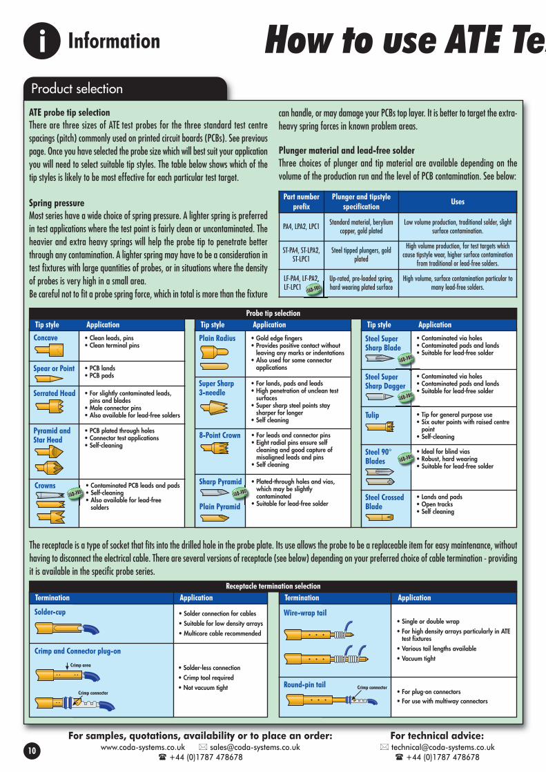
The receptacle is usually mounted into a probe plate. This plate canbe made of resin-laminated fibreglass (types such as G10 or FR4),or plastic materials such as nylon, perspex or polycarbonate. Usually,the probe plate used is made from fibreglass. Tungsten carbide drillbits are required to drill holes in this material. The thickness of theprobe plate should be such that it will support the total springpressure of all probes without it bending significantly. For very largearrays of probes it may be necessary to put some support pillarsunderneath to minimise this problem. For general purpose testapplications, an 8-10mm thickness of material is recommended.
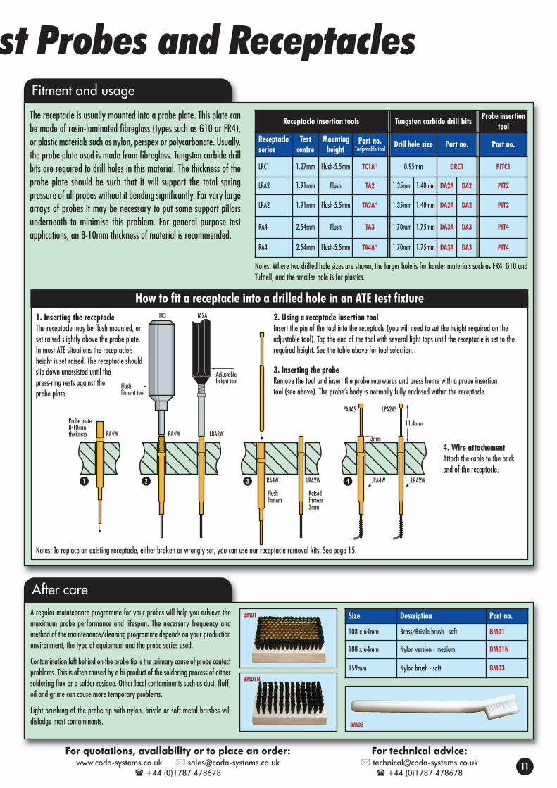
A regular maintenance programme for your probes will help you achieve themaximum probe performance and lifespan. The necessary frequency andmethod of the maintenance/cleaning programme depends on your productionenvironment, the type of equipment and the probe series used.
Contamination left behind on the probe tip is the primary cause of probe contactproblems. This is often caused by a bi-product of the soldering process of eithersoldering flux or a solder residue. Other local contaminants such as dust, fluff,oil and grime can cause more temporary problems.
Light brushing of the probe tip with nylon, bristle or soft metal brushes willdislodge most contaminants.
Size Description Part no.
108 x 64mm Brass/Bristle brush - soft BM01
108 x 64mm Nylon version - medium BM01N
159mm Nylon brush - soft BM03
BM03
BM01
BM01N
Probe plate8-10mmthickness RA4W
Flushfitment
TA3
RA4W LRA2W
TA2A
RA4W LRA2W
Raisedfitment3mm
3mm
11.4mm
LPA2ASPA4AS
1 2 3 4
Flushfitment tool
Adjustableheight tool
RA4W LRA2W
How to fit a receptacle into a drilled hole in an ATE test fixture
Receptacle insertion tools Tungsten carbide drill bitsProbe insertion
toolReceptacleseries
Testcentre
Mountingheight
Part no.*adjustable tool Drill hole size Part no. Part no.
LRC1 1.27mm Flush-5.5mm TC1A* 0.95mm DRC1 PITC1
LRA2 1.91mm Flush TA2 1.35mm 1.40mm DA2A DA2 PIT2
LRA2 1.91mm Flush-5.5mm TA2A* 1.35mm 1.40mm DA2A DA2 PIT2
RA4 2.54mm Flush TA3 1.70mm 1.75mm DA3A DA3 PIT4
RA4 2.54mm Flush-5.5mm TA4A* 1.70mm 1.75mm DA3A DA3 PIT4
11
Notes: To replace an existing receptacle, either broken or wrongly set, you can use our receptacle removal kits. See page 15.
1. Inserting the receptacleThe receptacle may be flush mounted, orset raised slightly above the probe plate.In most ATE situations the receptacle’sheight is set raised. The receptacle shouldslip down unassisted until thepress-ring rests against theprobe plate.
2. Using a receptacle insertion toolInsert the pin of the tool into the receptacle (you will need to set the height required on theadjustable tool). Tap the end of the tool with several light taps until the receptacle is set to therequired height. See the table above for tool selection.
3. Inserting the probeRemove the tool and insert the probe rearwards and press home with a probe insertiontool (see above). The probe’s body is normally fully enclosed within the receptacle.
4. Wire attachementAttach the cable to the backend of the receptacle.
Notes: Where two drilled hole sizes are shown, the larger hole is for harder materials such as FR4, G10 andTufnell, and the smaller hole is for plastics.
For quotations, availability or to place an order:www.coda-systems.co.uk [email protected]
+44 (0)1787 478678
For technical advice: [email protected]
+44 (0)1787 478678

Minimum test centres 2.54mmFull travel 6.35mmWorking travel 4.24mmSpring force at wkg travel(L) Extra light spring 57g(S) Light spring 114g(X) Heavy spring 170g(E) Extra heavy 227g(U) Ultra heavy spring 283g
Current rating DC cont (max) shown under each tip style
33.02 typical8.38
Max. travel 6.351.3733.02 typical
8.38
Max. travel 6.351.37
SUPER SHARP3-NEEDLE
PA4VSPA4VXPA4VEPA4VU
ST-PA4VSST-PA4VXST-PA4VEST-PA4VU
0.64
1.52
L. SPRINGH. SPRINGE.H. SPRINGU.H. SPRING
Diameter1.5mm1.5mm2.0mm2.0mm2.5mm3.5mm
LARGE PYRAMID HEADS
Current8 amps max
0.87
LF-PA4KXLF-PA4KELF-PA4KU
H. SPRINGE.H. SPRINGU.H. SPRING
ROBUST 90° BLADE
SUPER-SHARP BLADE
LF-PA4I8XLF-PA4I8ELF-PA4I8U
H. SPRINGE.H. SPRINGU.H. SPRINGCurrent 8 amps max
Current 8 amps max
Ideal for blind vias
PA4QPS-040PA4QPX-040PA4QPE-040PA4QPU-040
ST-PA4QPS-040ST-PA4QPX-040ST-PA4QPE-040ST-PA4QPU-040
0.87
1.5mm CROWNSelf-cleaning
PA4QS-060PA4QX-060
2.03
1.52
TULIP HEAD
PA4RSPA4RXPA4REPA4RU
ST-PA4RSST-PA4RXST-PA4REST-PA4RU
Self-cleaning
1.19
1.40
L. SPRINGH. SPRINGE.H. SPRINGU.H. SPRING
L. SPRINGH. SPRINGE.H. SPRINGU.H. SPRING
L. SPRINGH. SPRING
Current 8 amps max
Current 8 amps max
Current 3 amps max
Tip styles
Tip stylesSpecification
The PA4 series is the universal size for use at 2.54mm test centres in the majority of ATE test fixtures. It has a very widerange of tip styles for almost all test targets. Additionally, a wide choice of spring forces is available. The ST-PA4 series
adds hardened steel tips which ensure an exceptional resistance to wear in high volume PCB test production runs. The LF-PA4 series has hardened tips, extra-resilient plated surfaces and anenhanced pre-loaded spring pressure, to enable good penetration of the tough residual contamination often found on the surface of many lead-free solders.
CONCAVEHEAD
PA4ALPA4ASPA4AXPA4AU
ST-PA4ASST-PA4AXST-PA4AU
STEEL TIP
2.03
1.52
2.0
1.50
SPEAR POINT
FLAT HEAD - 1.5mm
PA4BSPA4BXPA4BEPA4BU
ST-PA4BSST-PA4BXST-PA4BEST-PA4BU
0.87
1.5mm SERRATEDHEAD
PA4HSPA4HXPA4HEPA4HU
ST-PA4HSST-PA4HXST-PA4HEST-PA4HU
2.02
1.52
E.L. SPRINGL. SPRINGH. SPRINGU.H. SPRING
L. SPRINGH. SPRINGE.H. SPRINGU.H. SPRING
L. SPRINGH. SPRINGE.H. SPRINGU.H. SPRING
Current 8 amps max
Current 8 amps max
Current 3 amps max
Current 8 amps max
REDUCED RADIUS(FOR CONNECTOR APPLICATIONS)
PA4JL-064PA4JS-064PA4JX-064PA4JU-064
0.87 0.64
6.35
E.L. SPRINGL. SPRINGH. SPRINGU.H. SPRINGCurrent 8 amps max
L. SPRINGH. SPRINGL. SPRINGH. SPRINGH. SPRINGH. SPRING
PA4TSPA4TXPA4TS-2.0PA4TX-2.0PA4TX-2.5*PA4TX-3.5*
LARGERSERRATEDHEADS
2.0mm2.5mm3.0mm4.0mm
L. SPRING H. SPRINGA diam.
9 serrations16 serrations16 serrations32 serrations
PA4HS-080PA4HS-100*PA4HS-120*PA4HS-160*
PA4HX-080PA4HX-100*PA4HX-120*PA4HX-160*
2.0
A Diam
Current 3 amps max *Not suitable for 2.5mm centres
*Not suitable for2.5mm centres
Ideal for landsand via holes
ROUND-PINS
RA4R
39.6ø 0.64
29.214.57
1.47 typical 1.68 typical 7.62 typical
STEEL CROSSED BLADE
ST-PA4LSST-PA4LXST-PA4LU
SHARP DAGGER
L. SPRINGH. SPRINGU.H. SPRING
H. SPRINGE.H. SPRINGU.H. SPRING
Current 8 amps max
Current 8 amps max
38.529.21
4.57
1.47 typical 1.68 typical 7.62 typical
ø 1.00
0.87
CRIMP - plug-on
RA4CPlug-on connector for tail: RJ3-C Shrink sleeve HSS3
SOLDER-CUP
RA4S
RA4W3*
RA4W
RA4W12
RA4WL
RA4WLL
RA4WLLL
29.214.571.22
typical
1.47 typical 1.68 typical 7.62 typical
1.83
30.234.57
1.47 typical 1.68 typical 7.62typical
1.83Press ring1.22
typical
RA4R-040 We suggest use of 1mm Ø connectors, such as RJ1-C(unwired plug).
8-POINT CROWN HEADSelf-cleaning
PA4ZSPA4ZXPA4ZEPA4ZU
2.03
1.52
L. SPRINGH. SPRINGE.H. SPRINGU.H. SPRING
Current 8 amps max Smaller diameter head available
PLAIN RADIUS1.00
PA4JSPA4JXPA4JU
L. SPRINGH. SPRINGU.H. SPRINGCurrent 3 amps max
2.03
1.70
Self-cleaning
STAR HEAD
PA4MSPA4MXPA4MU
L. SPRINGH. SPRINGU.H. SPRINGCurrent 3 amps max
PLAIN PYRAMID -0.9mm
PA4TS-036PA4TX-036PA4TE-036PA4TU-036
ST-PA4TS-036ST-PA4TX-036ST-PA4TE-036ST-PA4TU-036
0.87
PA4TS-041PA4TX-041PA4TE-041PA4TU-041
LF-PA4TX-041LF-PA4TE-041LF-PA4TU-041
L. SPRINGH. SPRINGE.H. SPRINGU.H. SPRING
L. SPRINGH. SPRINGE.H. SPRINGU.H. SPRING
Current 8 amps max
Current 8 amps max
0.9mm PLAINCROWN
Actual size
*Not suitable forvacuum fixtures
ATE Test Probes 2.54mm/0.1” centre spacing
PA4QS-018PA4QX-018PA4QU-018
LF-PA4QX-018LF-PA4QU-018
L. SPRINGH. SPRINGU.H. SPRINGCurrent 8 amps max
Current 8 amps max
SHARP 90° BLADE
LF-PA4IXLF-PA4IELF-PA4IU
H. SPRINGE.H. SPRINGU.H. SPRING
Ideal for blind vias
PA4QS-050PA4QX-050PA4QE-050PA4QU-050
LF-PA4QX-050LF-PA4QE-050LF-PA4QU-050
L. SPRINGH. SPRINGE.H. SPRINGU.H. SPRINGCurrent 8 amps max
PA4, ST-PA4 & LF-PA4 Series
WIRE-WRAP
0.64
12
For samples, quotations, availability or to place an order:www.coda-systems.co.uk [email protected]
+44 (0)1787 478678
For technical advice: [email protected]
+44 (0)1787 478678
PA4FSPA4FX
L. SPRING H. SPRING
STEEL TIP
STEEL TIP
STEEL TIP
STEEL TIP
STEEL TIP
STEEL TIP
LEAD-FREE
0.87
0.5mm SMALL CROWN
3.81
0.45
3.81
0.45
LF-PA4TX-042LF-PA4TE-042LF-PA4TU-042
0.810.89
1.70
0.91
SHARP PYRAMID
0.86
1.3mm CROWNSelf-cleaning
2.03
1.27
2.03
1.27
0.57
30.23
7.6
10.0
30.23
12.0
10.0
29.21
7.6
12.7
29.21
7.6
18.6
29.21
7.6
27.6
29.5
3.0
12.0
Mounting hole size: 1.7/1.75mm - 1.75mm drill is most commonly used: Drill part no. DA3 - RIT tool part no. TA3, TA4A
Receptacles

CRIMP
LRA2C
SOLDER-CUP
LRA2S
LRA2W
LRA2W3*
LRA2W10
LRA2WL
LRA2WLL
30.234.57
.889Typical
1.12Typical
1.32Typical
7.62Typical
1.42
30.234.57
.889Typical
1.12Typical
1.32Typical
7.62Typical
Press ring 1.42
The LPA2 series is the universal size for use at 1.91mm test centres in the majority of ATE test fixtures. It has avery wide range of tip styles for almost all test targets. Additionally, a wide choice of spring forces is available.
The ST-LPA2 series adds hardened steel tips which ensure an exceptional resistance to wear in high volume PCB test production runs. The LF-LPA2 series has hardened tips, extra-resilient platedsurfaces and an enhanced pre-loaded spring pressure, to enable good penetration of the tough residual contamination often found on the surface of many lead-free solders.
0.462.03
Self-cleaning
0.57
0.5mm SMALL CROWN
LPA2QS-018LPA2QX-018LPA2QU-018
LPA2QS-030LPA2QX-030LPA2QU-030
ST-LPA2QS-030ST-LPA2QX-030ST-LPA2QU-030
0.57
1mm 4-POINTCROWN HEAD
1.19
1.37
TULIP HEAD
LPA2RSLPA2RXLPA2RU
ST-LPA2QS-018ST-LPA2QX-018ST-LPA2QU-018
LF-LPA2QX-040LF-LPA2QU-040
ST-LPA2RSST-LPA2RXST-LPA2RU
4-POINT PLAIN CROWNSelf-cleaning
ST-LPA2TSST-LPA2TXST-LPA2TU
1.19
1.19
PYRAMID HEAD
LPA2TSLPA2TXLPA2TU
L. SPRINGH. SPRINGU.H. SPRING
L. SPRINGH. SPRINGU.H. SPRING
L. SPRINGH. SPRINGU.H. SPRING
L. SPRINGH. SPRINGU.H. SPRING
L. SPRINGH. SPRINGU.H. SPRING
H. SPRINGU.H. SPRING
L. SPRINGH. SPRINGU.H. SPRING
L. SPRINGH. SPRINGU.H. SPRING
0.99
Self-cleaning
1.19
H. SPRINGU.H. SPRING(8oz)U.H. SPRING(10oz)
LF-LPA2KXLF-LPA2KULF-LPA2KW
Tip styles
Specification Tip styles
1.19
2.03
0.57
CONCAVE HEAD
SPEAR POINT
LPA2ASLPA2AXLPA2AU
LPA2BSLPA2BXLPA2BU
ST-LPA2BSST-LPA2BXST-LPA2BU
SERRATED HEAD
LPA2HSLPA2HXLPA2HU
ST-LPA2HSST-LPA2HXST-LPA2HU
1.19
2.02
0.57
Full radius
PLAIN RADIUS
LPA2JSLPA2JXLPA2JU
ST-LPA2JSST-LPA2JXST-LPA2JU
L. SPRING H. SPRINGU.H. SPRING
L. SPRING H. SPRINGU.H. SPRING
L. SPRING H. SPRINGU.H. SPRING
L. SPRING H. SPRINGU.H. SPRING
Self-cleaning
1.19
STAR HEAD
LPA2MSLPA2MXLPA2MU
ST-LPA2MSST-LPA2MXST-LPA2MU
L. SPRINGH. SPRINGU.H. SPRING
ST-LPA2VSST-LPA2VXST-LPA2VU
SUPER SHARP 3-NEEDLE
LPA2VSLPA2VXLPA2VU
0.64
1.52
LF-LPA2ZXLF-LPA2ZU
L. SPRING H. SPRINGU.H. SPRING
H. SPRINGU.H. SPRING
Smaller diameterhead available
LF-LPA2TX-025LF-LPA2TU-025
H. SPRINGU.H. SPRING
SHARP PYRAMID
LPA2TS-030LPA2TX-030LPA2TU-030
0.57
L. SPRINGH. SPRINGU.H. SPRING
H. SPRINGU.H. SPRING
ATE Test Probes 1.91mm/0.075” centre spacing
*Not suitable forvacuum fixtures
0.57
STEEL CROSSED BLADE
ST-LPA2LSST-LPA2LXST-LPA2LU
L. SPRINGH. SPRINGU.H. SPRING
LF-LPA2IXLF-LPA2IULF-LPA2IW
H. SPRINGU.H. SPRING(8oz)U.H. SPRING(10oz)
Ideal for blind vias
LF-LPA2I8XLF-LPA2I8ULF-LPA2I8W
H. SPRINGU.H. SPRINGU.H. SPRING(10oz)
Ideal for blind vias
Ideal for landsand via holes
13
LPA2, ST-LPA2 & LF-LPA2 Series
38.4ø 1.00
30.234.57
1.12 Typical 1.32 Typical7.62
Typical
LRA2R
LRA2R-040 We suggest use of 1mm Ø connectors, such as RJ1-C (unwired plug).
0.64
WIRE-WRAP
For samples, quotations, availability or to place an order:www.coda-systems.co.uk [email protected]
+44 (0)1787 478678
For technical advice: [email protected]
+44 (0)1787 478678
Minimum test centres 1.91mmFull travel 6.35mmWorking travel 4.24mmSpring force at wkg travel(S) Light spring 113g(X) Heavy Spring 170g(U) Ultra heavy spring 227g(W) Ultra heavy spring 283g
Current rating DC cont (max) 6 Amps
33.02
1.02 Full travel 6.35
8.38
33.02
1.02
6.86
Full travel 6.35
Actual size
STEEL TIP
STEEL TIP
STEEL TIP
STEEL TIP STEEL TIP
STEEL TIP
STEEL TIP
STEEL TIP
STEEL TIP
LEAD-FREE
0.57
SUPER SHARP BLADE
LF-LPA2TX-030LF-LPA2TU-030
0.57
SHARP DAGGER
13° 0.560.61
1.40
0.99
Self-cleaning
1.19
LPA2QS-040LPA2QX-040LPA2QU-040
SHARP 90° BLADE
0.57
ROBUST 90° BLADE
0.57
8-POINT CROWNSelf-cleaning
1.19
ROUND-PINS
39.70ø 0.64
30.234.57
1.12 Typical 1.32 Typical7.62
Typical
30.0
7.6
12.7
30.0
10.0
10.0
30.0
7.6
17.6
30.0
7.6
26.5
29.5
3.0
10.5
Mounting hole size: 1.35/1.40mm - 1.4mm drill is most commonly used: Drill part no. DA2 - RIT tool part no. TA2A, TA2
Receptacles

0.78 8.38
0.5043.18
0.78 8.38
0.5043.18
SERRATED HEAD
LPC1HSLPC1HXLPC1HU
0.89
ST-LPC1HSST-LPC1HXST-LPC1HU
PLAIN RADIUS
LPC1JSLPC1JXLPC1JU
0.5
L. SPRING H. SPRINGU.H. SPRING
L. SPRING H. SPRINGU.H. SPRING
SPEAR POINT
LPC1BSLPC1BX
L. SPRING H. SPRING ST-LPC1TS-020
ST-LPC1TX-020ST-LPC1TU-020
ST-LPC1TS-038ST-LPC1TX-038ST-LPC1TU-038
CRIMP
LRC1C
SOLDER-CUPPLUG-ON PLUG
LRC1SLRC1P Receptacle
Used with LRC1P
CR30 (blue) for 30 AWG wire
PLAIN PYRAMID
PYRAMID HEAD
LPC1TS-020LPC1TX-020LPC1TU-020
LPC1TS-038LPC1TX-038LPC1TU-038
LPC1USLPC1UXLPC1UU
8.89
1.0539.88
Ø 0.95 11.71 Typ.
40.41
0.76 I.D.
7.37 Typ.
5.08 Typ.
0.5
L. SPRING H. SPRINGU.H. SPRING
L. SPRING H. SPRINGU.H. SPRING
L. SPRING H. SPRINGU.H. SPRING
.97
2.03
0.97
8.89
4.83
39.880.760.56
Ø 1.22Insulation Dia.
5.08
0.72 0.58
The LPC1 series is the universal size for use at 1.27mm test centres in the majority of ATE test fixtures. It has avery wide range of tip styles for almost all test targets. Additionally, a wide choice of spring forces is available.
The ST-LPC1 series adds hardened steel tips which ensure an exceptional resistance to wear in high volume PCB test production runs. The LF-LPC1 series has hardened tips, extra-resilient platedsurfaces and an enhanced pre-loaded spring pressure to enable good penetration of the tough residual contamination often found on the surface of many lead-free solders.
Tip styles
Specification
Mounting hole size: 0.97/0.99mm 0.95mm drill is most commonly used: Drill part no. DRC1 RIT tool part no. TC1A and TRC1
Receptacles
ATE Test Probes 1.27mm/0.050” centre spacing
ATE Travel Indicator Probes
Minimum test centres 1.27mm
Full travel 6.35mm
Working travel 4.24mm
Pointing accuracy 0.05mm
Spring force at wkg travel
(S) Light spring 114g
(X) Heavy spring 170g
(U) Extra heavy spring 227g Actual size
LPI2HSSpring force: 113gLPI2HXSpring force: 170g
Test centres 1.91mm
1.50
0.4
0.92TYP
Shroud
PI4HS 114g PI4HX 170g PI4HE 227gTest centres 2.54mm
2.03
0.4
1.5TYP
PI4HMS 114gPI4HMX 170gTest centres 4.0mm
3.61
0.4
2.76TYP
SMALL SERRATED HEAD
LARGE SERRATED HEAD
SERRATED HEAD
Insulated head probes are used for circuit board component lead detectionand testing. The insulating shroud is raised slightly higher than the metal
serrated tip. During test, if the component lead or connector pin is set correctly, the electricalcontact will be made. Pins absent or misaligned will cause the shroud to make contact first andfail the test.
A useful series of devices for measuring the travel at any probeposition in a test fixture. After the PCB is fully down onto the probe
field, the indicator probes remain compressed. The change in length indicates the travel.
Do not insert into the receptacle by pressing on the plunger!
Component LeadDetection
Component PinDetection
Pass Fail Pass Fail
How to use insulated head probesIt is often a requirement to provide a multi-purpose test ontoa single component or connector lead. The probes will fit intostandard ATE receptacles and require just one wire connection.The insulated head probe will:• Presence test the pin to check it’s set to the correct height• Check whether the pin has passed through the hole• Instigate an electrical test to ensure that the pin is
soldered properly to its pad, in combination with otherprobes in the test fixture
• Fail any leads that have been bent over significantly.Reason for failure:Pin set incorrectly
Reason for failure:Pin missing
ReceptaclesFit into existing receptacles in your fixture
Tip stylesFLAT HEAD - 2mm centres
TIP2F 1.19
2.02
0.61
Full radius
RADIUS - 2mm centres
TIP2J
FLAT HEAD - 2.54mm centres
TIP4F
1.52
1.52
RADIUS - 2.54mm centres
TIP4J
0.91
0.91
LONG TRAVEL FLAT HEAD
TIPL4F
1.52
1.52
LONG TRAVEL RADIUS
TIPL4J
OAL = 37.1mm OAL = 37.1mm
Receptacle LRA2 series; see page 13
Receptacle RA4 series; see page 12
Receptacle RA4 series; see page 12
Ideal for blind vias
LPC1, ST-LPC1 & LF-LPC1 Series
PI Series TIP Series
H. SPRINGU.H. SPRING
STEEL ONLY
H. SPRINGU.H. SPRING
Ideal for landsand via holes
Presence detection using an insulating shroud
14
For LPA2 series
For PA4 series
For LPA4 series
For samples, quotations, availability or to place an order:www.coda-systems.co.uk [email protected]
+44 (0)1787 478678
For technical advice: [email protected]
+44 (0)1787 478678
STEEL TIP
STEEL TIP
STEEL TIP
LEAD-FREE
SUPER SHARP DAGGER
0.5
LF-LPC1TX-021LF-LPC1TU-021
0.46
0.5 Typical
0.46
0.5 Typical
SMALL 3-POINT CROWNSelf-cleaning
LF-LPC1UXLF-LPC1UU
0.5
90°
ROBUST 90° BLADE
LF-LPC1I8XLF-LPC1I8U

ATE Test Probe and Receptacle Tools
Receptacle Removal Kits
For the removal of ATE. receptacles which areeither worn or broken. Three kits are availableto make a once difficult job very easy. Aseparate kit is required for each standard testcentre spacing. Each kit contains a tool to
initially set the receptacle flush and another tool topunch the receptacle all the way through the hole.Coda-Pin receptacle insertion tools are required to installthe new receptacle (see above).
Test Centre Recept. Series Part no.2.54mm RA4 RRTRA41.91mm LRA2 RRTLRA21.27mm LRC1 RRTLRC1
RRTRA4
Probe Removal Hooks
Probe Insertion Tools
For the removal of headed probes inthe LPA2, ELPA2, PA4, LPA4 andELPA4 series from crowded testfixtures. Only for head sizes 1.2 to2.0mm.
Test Centre Description Part no.
1.91mm ATE test probes (headed) PRTA2
2.54mm ATE test probes (headed) PRTA4
PRTA2
PRTA4
Receptacle Insertion Tools
These PIT’s allow the installation of certain series of test probes into their receptacles withless risk of damage by handling.
Test Probe Series Part no.
LPC1 PITC1
LPA2, PA2, ELPA2 PIT2
PA4, LPA4, ELPA4 PIT4
PITC1
PIT2
PIT4
Receptacle insertion tools arerequired for inserting the ATEreceptacle into the hole withoutdamage to the tube, particularly ifyou are using harder materials forthe probe plate. With a correctly sized drilled hole,the receptacle should slideunassisted down to the press-ring. The insertion tool will takeover the insertion from here. In most ATE applications the receptacle’s height is usuallyset as raised, so we supply adjustable height receptacle tools for inserting them. See the‘How to fit’ box for more information - page 11.
Series Test Centre Mounting Height Part no.*adjustable
LRC1 1.27mm Flush-7.24mm TC1A*
LRA2 1.91mm Flush TA2LRA2 1.91mm Flush-5.59mm TA2A*
RA4 2.54mm Flush TA3RA4 2.54mm Flush-5.59mm TA4A*
TA4A
Pass Marking Unit
Probe Plate
Typically 1.30 1.7 - 2.0
Minimum 8mmthickness
Spacer
6.35
48.51
0.64
11.85
3.18
60°Black (-)
Red (+)
Receptacle BMR-1(included wih BMP-1)
Warning: Adequate thickness spacersMUST be used to limit board travel asshown. Failure to use proper spacerswill allow the scriber to bottom out,stalling the motor and permanentlydamaging the marker.
BMP-1BMP-1
Scriber Specification
Example fitment methods
PASS MARKING UNIT
The BMP-1 test pass marking unit is intended for installation into test fixtures andproduction equipment. Upon receipt of test a pass signal it will rapidly scribe a permanentcircular mark onto the unit under test removing the risk of human error. This compact unitrequires a footprint of less than 15mm2 on the test board. The spring loaded carbide tipis long lasting and its hardness will mark bare fibreglass (FR4), solder mask over glassor copper, bare tinned copper, plastics and metal castings.
The unit is supplied with a mounting receptacle with knurled fitment, cables and aplug/socket kit allowing easy connection to the jig’s internal wiring. The scriber can easilybe unscrewed from its receptacle so it can be transported for use in other positions. Extrareceptacles, an insertion tool and tip replacement parts are available as spares and theseare listed within the specifications.
MechanicalFull marker tip travel 1.57mmRecommended working travel 1.27mmDirection of rotation CCWScribed diameter 1.27mmMounting hole size 11.89/11.91mm
Electrical (Operating Conditions)Current rating 50mAVoltage required 12 - 15VDCRecommended duty cycle 1 sec. On (min)
5 sec. Off
Materials and FinishesPlunger tip Carbide steelReceptacle Stainless steel
Spares/Accessories Part No.Receptacle insertion tool RIT-BMPReceptacle extraction tool EXT-BMPSpare receptacle BMR-1Replacement carbide tip BMT-1
15
For quotations, availability or to place an order:www.coda-systems.co.uk [email protected]
+44 (0)1787 478678
For technical advice: [email protected]
+44 (0)1787 478678

Bench-top Test Jigs and Accessories
Uncomplicated test jig, using ahinged lid and push fingers forcompression. Ideal for selfcustomisation
MF series
Robust test jig using acam-operated, horizontal, rigidpush plate for compression.Ideal for self customisation
CMF series
Advanced test jig, using a cam-operated gate, with fullyadjustable push fingers forcompression. Ideal for selfcustomisation
How to fit test probes andreceptacles into a bench-top test jig
CGF series
Robust, easily customised, standalone kits for testing a variety of PCBs, such as those containing conventional and surface mount circuitry. There are three versions - basic hinged-top, cam-operated pusher plate or advanced cam-operated gate with fully adjustable push-fingers.
Typical examples of their usage are:• Low to medium volume testing of PCBs - such as power supplies and control boards• Functional testing and alignment of modules and sub-assemblies• Repair and calibration stations• Probing of both sides of the PCB is possible
You can use these jigs as the basis to build your own test station. We can suggest a jig customising specialist who could do the work for you.
Page17
Page18
Page19
Page20
16
i Information
For quotations, availability or to place an order:www.coda-systems.co.uk [email protected]
+44 (0)1787 478678
For technical advice: [email protected]
+44 (0)1787 478678

Clear polycarbonate lidallows visibility of UUT(space under lid whenclosed - 41mm)
Two Carlson springs allow the top plate to remainopen at any position (except MF0SC)
Probe plate will open on hinges, allowing access to the pan(probe plate thickness - 9.75mm)
All sides and baseplate can be removedfor drilling. 100mmdeep pan is suppliedas standard
Robust handle andlatch assembly
Probe plate lockingscrew
Fixture customisation accessories suitable for MF series
Pan latch button and locking screw
M4 x 0.77.0
25.0 4.0 23.052.0
Ø 6.0 Ø D Short tapershown
Long length tooling pins, with an M4 thread, suitable for loaded board testing.M4 nut and washer included. Bullet nose tip. Drill hole size: 3.95 - 4.00mm
Push fingers for pressing the PCB on to the probe field Hole size: 6.35mm
Rigid tooling pins (pegs for locating PCB guide holes) Guide plates for guiding the edge of thePCB nearer and to giving some protection tothe tooling pins and probes.
PF1
GPW1
16.818.0
6.0
2-6 x 3.5
39.0
MF1SCS
Coda part no. Base box size W x L x D (mm) Max U.U.T. (mm) Max probe count (6oz probes) Notes
MF0SC 100 x 150 x 65 75 x 75 25MF1SC and upwards feature side handles and carlson springs(which allow the top plate to remain open at any position).
MF1SCS, MF2SCS and MF3SCS have the latch on the longest side.
MF1SC 200 x 300 x 100 150 x 150 150MF1SCS 300 x 200 x 100 230 x 100 150MF2SC 300 x 400 x 100 250 x 250 200MF2SCS 400 x 300 x 100 330 x 170 200MF3SC 400 x 500 x 100 350 x 350 250MF3SCS 500 x 400 x 100 430 x 250 250
Coda part no. Ø D (mm) Pin tip shapeRLTP1.95 1.95 short taper 3mmRLTP2.45 2.45 short taper 3mmRLTP2.95 2.95 short taper 3mmRLTP3.15 3.15 short taper 3mmRLTP3.45 3.45 short taper 3mmRLTP3.75 3.75 short taper 3mmRLTP3.85 3.85 short taper 3mmRLTP3.95 3.95 short taper 3mmRLTP4.45 4.45 long taper 10mm
Bench-top Test Jig MF series Uncomplicated test jig, using a hinged lid for compression.Ideal for self customisation.
The MF series is designed to test simpler PCBs, such asthose containing low density, conventional circuitry.Typical examples of their usage are:
• Repair and calibration stations
• Testing PCBs such as power supplies and control boards
• Modules and sub-assembly alignment
This series has a hinged polycarbonate top plate which, whenlatched closed, and using the supplied push fingers, puts adownward force onto the PCB and the test probes.
MF series extra options
Series Test centres PageLPA2 1.91mm 13PA4 2.54mm 12PA5 3.2mm 7PA6 4.75mm 7
Coda part no. Description
ExampleMF1SCS+SH Shallow pan, 65mm deep instead of 100mm
MF2SCS+SLOPEMF3SCS+SLOPE
Sloping pan, so that the probe plate faces you a little more(available for MF2SCS and MF3SCS)
ExampleRBS12 Riser block sets - for PCBs with taller components (6 - 25mm)
MF1BOXSMF2BOXS
Pan and probe board only (no hinged lid); for open access to theunit under test
PF1 Extra push fingers
TK1 Tool kit for disassembling MF series
Recommended Coda-Pin™ probes for the MF series• HD-PA4 to HD-PA6 series for high current
applications• Switching probes, such as PS3 and PS6, for
presence detection applications
Maximumheight: 37mm
Note: not suitable for MF0SC
17
For quotations, availability or to place an order:www.coda-systems.co.uk [email protected]
+44 (0)1787 478678
For technical advice: [email protected]
+44 (0)1787 478678

Cam operation ensuresa true linear motion ofthe top plate
Sturdy framework keeps top plate stable
Anti slam gas springs
Robust handle and latch for the lid (space under lid when closed - 41mm)All sides and base platewill remove forcustomisation. 100mmdeep pan supplied asstandard
Robust handle to operatethe cam system with aninterlock
Carry handle
Probe plate lockingscrew
CMF2
The CMF series uses fixed position push fingers and is designedto test low to medium density PCBs, such as those containingconventional and surface mount circuitry.Typical examples of their usage are:
•Repair and calibration stations
•Low to medium volume testing of PCBs - such as power suppliesand control boards
•Single or double-sided PCB probing
This series has a cam-operated G10 fibreglass push plate. When the lidis latched closed the handle will then push down the upper plate, withthe provided pusher rods, ensuring a true linear downward motion ontothe PCB. Test probes can be fitted into both the base pan’s probe plateand, to a limited extent, on the top plate allowing some double-sidedprobing. The optional stripper plate supports the PCB and protects theprobe field.
Bench-top Test Jig CMF series Robust test jig using a cam-operated horizontal probeplate. Ideal for self customisation.
Base probe plate will open on hinges to allow accessinside the pan (probe plate thickness - 9.75mm)
Fixture customisation accessories suitable for CMF series
M4 x 0.77.0
25.0 4.0 23.052.0
Ø 6.0 Ø D Short tapershown
Long length tooling pins, with an M4 thread, suitable for loaded board testing.M4 nut and washer included. Bullet nose tip. Drill hole size: 3.95 - 4.00mmNote: You may need to drill the push plate to allow the tooling pin to pass through.
Rigid tooling pins (pegs for locating PCB guide holes)
5.02.9 3.05 3.3
Tailmoves
14.021.0
Ø D
Floating pins for keeping the PCB raised away from the test probes until thetop plate is lowered. Also useful for leveling pressure in unpopulated areas.
Drill hole size: 2.95 - 3.00mm FP1-35 300g spring force, tip diameter 3.5mmFP1-60 300g spring force, tip diameter 6.0mm
Coda part no. Ø D (mm) Pin tip shape
RLTP1.95 1.95 short taper 3mm
RLTP2.45 2.45 short taper 3mm
RLTP2.95 2.95 short taper 3mm
RLTP3.15 3.15 short taper 3mm
RLTP3.45 3.45 short taper 3mm
RLTP3.75 3.75 short taper 3mm
RLTP3.85 3.85 short taper 3mm
RLTP3.95 3.95 short taper 3mm
RLTP4.45 4.45 long taper 10mm
Including stripper plate Without stripper plate Base box sizeW x L x D (mm)
Max U.U.T.(mm)
Max node count(6oz probes)
Notes
CMF1+SP CMF1 200 x 300 x 100 140 x 220 300‘S’ suffix means that thelatch is on the long side ofthe pan. Width (W) is thelatch/hinge side. Depth (D)is the pan’s internal depth.
CMF1S+SP CMF1S 300 x 200 x 100 240 x 110 300CMF2+SP CMF2 300 x 400 x 100 225 x 300 600CMF2S+SP CMF2S 400 x 300 x 100 340 x 220 550CMF3+SP CMF3 400 x 500 x 100 340 x 400 600CMF3S+SP CMF3S 500 x 400 x 100 440 x 310 600CMF4S+SP CMF4S 600 x 500 x 100 550 x 420 800
Part numbers
NOTE: The cam system may differ visually from the mechanism shown in the illustration.
Coda part no. Description
Example CMF2S+SH Shallow pan 65mm deep instead of 100mm
ExampleCMF2S+SLOPE
CMF3S+SP+SLOPE
Sloping pan so that the probe plate faces you a little more (available for jigs with (S) suffix only)
Example RBS12 Riser block sets - for PCBs with taller components
PF1 PCB push fingers
TK1 Tool kit for disassembling CMF series 1 x 5⁄32”, 1 x 1⁄8”, 1 x PH2
Contact us for details Upper head unit only, no pan or probe plate
Contact us for details Transparent polycarbonate top plate - for PCB visibility
Contact us for details Full range of spare parts available
CMF series extra options
Recommended Coda-Pin™ probes for the CMF series
Series Test centres PageLPA2 1.91mm 13PA4 2.54mm 12PA5 3.2mm 7PA6 4.75mm 7
• HD-PA4 to HD-PA6 series for highcurrent applications.
• Switching probes, such as PS3 andPS6, for prescence detectionapplications.
Push fingers for pressing the PCBon to the probe field. Hole size: 6.35mmMaximum height 37mmPF1
18
For quotations, availability or to place an order:www.coda-systems.co.uk [email protected]
+44 (0)1787 478678
For technical advice: [email protected]
+44 (0)1787 478678
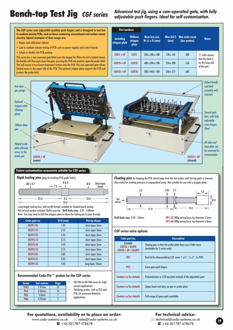
CGF2S+SP(open)
CGF2S+SP(closed)
Hinged probeplate allowingaccess to theinside pan
Robust handleand latchassembly withinterlock
All sides andbase plate canbe removed forcustomisation
100mm deeppan
Optionalstripper plate(floatingplate) Several gate
bars, with fullyadjustablepress fingersfitted
Anti-slamgas springs
Advanced test jig, using a cam-operated gate, with fullyadjustable push fingers. Ideal for self customisation.
Fixture customisation accessories suitable for CGF series
M4 x 0.77.0
25.0 4.0 23.052.0
Ø 6.0 Ø D Short tapershown
Long length tooling pins, with an M4 thread, suitable for loaded board testing.M4 nut and washer included. Bullet nose tip. Drill hole size: 3.95 - 4.00mmNote: You may need to drill the stripper plate to allow the tooling pin to pass through.
Rigid tooling pins (pegs for locating PCB guide holes)
5.02.9 3.05 3.3
Tailmoves
14.021.0
Ø D
Floating pins for keeping the PCB raised away from the test probes until the top plate is lowered.Also useful for leveling pressure in unpopulated areas. Not suitable for use with a stripper plate.
Drill hole size: 2.95 - 3.0mm FP1-35 300g spring force, tip diameter 3.5mmFP1-60 300g spring force, tip diameter 6.0mm
Bench-top Test Jig CGF series
Coda part no. Ø D (mm) Pin tip shape
RLTP1.95 1.95 short taper 3mm
RLTP2.45 2.45 short taper 3mm
RLTP2.95 2.95 short taper 3mm
RLTP3.15 3.15 short taper 3mm
RLTP3.45 3.45 short taper 3mm
RLTP3.75 3.75 short taper 3mm
RLTP3.85 3.85 short taper 3mm
RLTP3.95 3.95 short taper 3mm
RLTP4.45 4.45 long taper 10mm
Includingstripper plate
Withoutstripperplate
Base box sizeW x L x D (mm)
Max U.U.T.(mm)
Max node count(6oz probes) Notes
CGF1+SP CGF1 220 x 300 x 100 120 x 185 300 ‘S’ suffix meansthat the latch ison the long sideof the pan.
CGF2S+SP CGF2S 400 x 300 x 100 250 x 200 550
CGF3S+SP CGF3S 500 x 400 x 100 350 x 275 600
Part numbersThe CGF series uses adjustable position push fingers and is designed to test lowto medium density PCBs, such as those containing conventional and surface mountcircuitry. Typical examples of their usage are:
• Repair and calibration stations
• Low to medium volume testing of PCBs such as power supplies and control boards
• Single or double side PCB probing
This series has a cam-operated gate fitted onto the hinged lid. When the lid is latched closed,the handle will then push down the gate, pressing the PCB into position upon the probe field.This will ensure a true linear downward motion onto the PCB. The cam-operated gate allowslimited access to the upper side of the PCB. The optional stripper plate supports the PCB andprotects the probe field.
CGF series extra options
Recommended Coda-Pin™ probes for the CGF series
Series Test centres PageLPA2 1.91mm 13PA4 2.54mm 12PA5 3.2mm 7PA6 4.75mm 7
• HD-PA4 to HD-PA6 series for highcurrent applications.
• Switching probes, such as PS3 andPS6, for prescence detectionapplications.
19
For quotations, availability or to place an order:www.coda-systems.co.uk [email protected]
+44 (0)1787 478678
For technical advice: [email protected]
+44 (0)1787 478678
Coda part no. Description
ExampleCGF2S+SLOPE
CGF3S+SP+SLOPE
Sloping pan so that the probe plate faces you a little more (available for S series only)
TK1 Tool kit for disassembling CGF series 1 x 5⁄32”, 1 x 1⁄8”, 1 x PH2
PF2 Extra gate push fingers
Contact us for details Polycarbonate or G10 top plate instead of the adjustable gate
Contact us for details Upper head unit only, no pan or probe plate
Contact us for details Full range of spare parts available
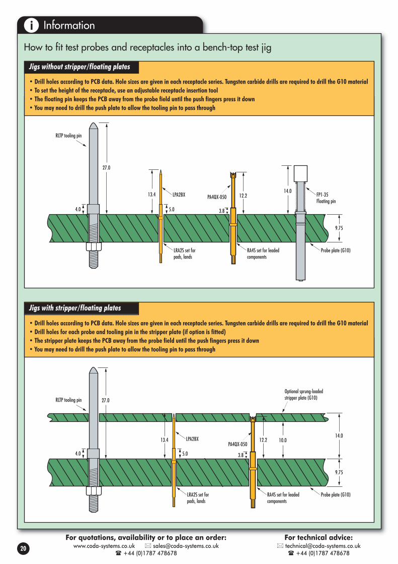
RLTP tooling pin
4.0 5.0
13.4 LPA2BX
LRA2S set forpads, lands
RA4S set for leadedcomponents
PA4QX-05012.2
3.8
10.0
9.75
14.0
Probe plate (G10)
Optional sprung-loadedstripper plate (G10)
RLTP tooling pin
4.0 5.0
LPA2BX
LRA2S set forpads, lands
RA4S set for leadedcomponents
PA4QX-050 12.2
3.8
9.75
Probe plate (G10)
13.4
27.0
27.0
14.0FP1-35Floating pin
Information
How to fit test probes and receptacles into a bench-top test jig
• Drill holes according to PCB data. Hole sizes are given in each receptacle series. Tungsten carbide drills are required to drill the G10 material• To set the height of the receptacle, use an adjustable receptacle insertion tool• The floating pin keeps the PCB away from the probe field until the push fingers press it down• You may need to drill the push plate to allow the tooling pin to pass through
• Drill holes according to PCB data. Hole sizes are given in each receptacle series. Tungsten carbide drills are required to drill the G10 material• Drill holes for each probe and tooling pin in the stripper plate (if option is fitted)• The stripper plate keeps the PCB away from the probe field until the push fingers press it down• You may need to drill the push plate to allow the tooling pin to pass through
RLTP tooling pin
4.0 5.0
13.4 LPA2BX
LRA2S set forpads, lands
RA4S set for leadedcomponents
PA4QX-05012.2
3.8
10.0
9.75
14.0
Probe plate (G10)
Optional sprung-loadedstripper plate (G10)
RLTP tooling pin
4.0 5.0
LPA2BX
LRA2S set forpads, lands
RA4S set for leadedcomponents
PA4QX-050 12.2
3.8
9.75
Probe plate (G10)
13.4
27.0
27.0
14.0FP1-35Floating pin
Jigs without stripper/floating plates
Jigs with stripper/floating plates
20
i
For quotations, availability or to place an order:www.coda-systems.co.uk [email protected]
+44 (0)1787 478678
For technical advice: [email protected]
+44 (0)1787 478678
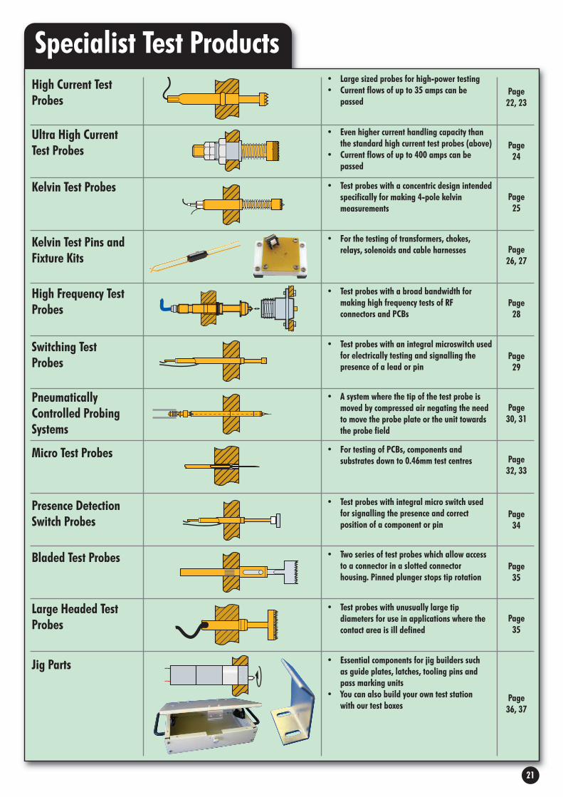
Specialist Test Products
Switching TestProbes
• Test probes with an integral microswitch usedfor electrically testing and signalling thepresence of a lead or pin
• For testing of PCBs, components andsubstrates down to 0.46mm test centres
• A system where the tip of the test probe ismoved by compressed air negating the needto move the probe plate or the unit towardsthe probe field
• Test probes with a concentric design intendedspecifically for making 4-pole kelvinmeasurements
• Large sized probes for high-power testing• Current flows of up to 35 amps can be
passed
• Even higher current handling capacity thanthe standard high current test probes (above)
• Current flows of up to 400 amps can bepassed
• Test probes with a broad bandwidth formaking high frequency tests of RFconnectors and PCBs
• Test probes with integral micro switch usedfor signalling the presence and correctposition of a component or pin
• Two series of test probes which allow accessto a connector in a slotted connectorhousing. Pinned plunger stops tip rotation
• Test probes with unusually large tipdiameters for use in applications where thecontact area is ill defined
High Current TestProbes
Ultra High CurrentTest Probes
Micro Test Probes
PneumaticallyControlled ProbingSystems
Kelvin Test Probes
Kelvin Test Pins andFixture Kits
Bladed Test Probes
High Frequency TestProbes
Presence DetectionSwitch Probes
Large Headed TestProbes
Jig Parts
• For the testing of transformers, chokes,relays, solenoids and cable harnesses
Page22, 23
Page24
Page25
Page26, 27
Page28
Page29
Page30, 31
Page32, 33
Page34
Page35
Page35
Page36, 37
• Essential components for jig builders suchas guide plates, latches, tooling pins andpass marking units
• You can also build your own test stationwith our test boxes
21

CONCAVE HEAD
HD-PA4AS
SPEAR POINT
HD-PA4BS
0.91
SERRATED HEAD
HD-PA4HS
2.03
1.52
CONCAVE HEAD
L. SPRING H. SPRINGHD-PA3AS HD-PA3AX
SPEAR POINT
L. SPRING H. SPRINGHD-PA3BS HD-PA3BX
L. SPRING H. SPRINGHD-PA3HS HD-PA3HX
2.03
1.80
1.02
PLAIN RADIUS
SERRATED HEAD
1.02
L. SPRING H. SPRINGHD-PA3JS HD-PA3JX
1.8
2.0
SOLDER-CUP - with press-ring
RA3S
Press ring1.781.22
Typical
3.1724.1
1.47 Typical 1.68 6.09
SOLDER-IN
RA3P
18.67 1.78
1.68 Typical 6.09
Tip styles
Full travel 4.2mmWorking travel 2.9mmSpring force initial at wkg travel(S) Light spring 37g 79g(X) Heavy spring 77g 196g
Operating temp. range –55°C to +105°CCurrent rating DC cont (max) 8 AmpsMinimum test centres 2.54mm
24.641.37
6.3
Full travel 4.2
Actual size
Full travel 6.35mmWorking travel 4.24mmSpring force initial at wkg travel
24g 114gOperating temp. range –55°C to +150°CCurrent rating DC cont (max) 10 AmpsMinimum test centres 2.54mm
Tip styles
33.021.37
8.38
Full travel 6.35
Actual size
Full travel 6.35mmWorking travel 4.24mmSpring force initial at wkg travel
(S) Light 44g 126g(X) Heavy (where shown) 71g 164g
Operating temp. range –55°C to +150°CCurrent rating DC cont (max) 15 AmpsMinimum test centres 3.18mm
This range of test probes can be used for load and functional testing of power components such as semi-conductors, solenoids, loaded PCBs, bus-bars, wound components and batteries. Theyshare identical dimensions and will readily intermix with the PA3, PA4 and PA5 series general purpose test probes. In particular, the HD-PA4 series is physically interchangeable with the PA4series used in standard ATE test fixtures.
CONCAVE HEAD
HD-PA5AS
BULLET NOSE
HD-PA5BS
1.3
Radius = 0.25
2.54
2.03
PYRAMID HEAD - 2.5mm
2.50
L. SPRING H. SPRINGHD-PA5TS HD-PA5TX
SOLDER-CUP
RA5S
ReceptacleMounting hole size: 2.39/2.44mm2.4mm drill is most commonly used: Drill part no. DA5RIT tool part no. TA5
2.03
1.52
29.214.57
1.22Typical
1.47 Typical 1.68 Typical 7.62Typical
Press ring 1.8330.48
1.19Typical 1.47
Typical2.36
Typical7.62
Typical
4.57 Press ring 2.49
SOLDER-CUP
RA4S
ReceptacleMounting hole size: 1.7/1.75mm1.75mm drill is most commonly used: Drill part no. DA3/DA3ARIT tool part no. TA3
Actual size
33.022.03
8.38
Full travel 6.35
Tip styles
PLAIN SERRATED
L. SPRINGHD-PA5HPS
H. SPRINGHD-PA5HPX 1.70
LARGE SERRATED HEAD -3.9mm
H. SPRING HD-PA5HX-3.9
L. SPRING
Not suitable for 3.18mm test centres
HD-PA5HS-3.9
1.52
3.9
SERRATED HEAD - 2.5mm
2.54
L. SPRINGHD-PA5HS
H. SPRINGHD-PA5HX (2.4mm)
Example installations
SpecificationHD-PA3 Series SpecificationHD-PA4 Series SpecificationHD-PA5 Series
High Current Test Probes For load and functional testing of power components
6.1mm
RA3S
8.4mm
RA4S
HD-PA3ASHD-PA4AS 8.4mm
RA5S
HD-PA5AS6.1mm
RA3S
8.4mm
RA4S
HD-PA3ASHD-PA4AS 8.4mm
RA5S
HD-PA5AS6.1mm
RA3S
8.4mm
RA4S
HD-PA3ASHD-PA4AS 8.4mm
RA5S
HD-PA5AS
RA3SF Hole size: 1.70mm
22
For samples, quotations, availability or to place an order:www.coda-systems.co.uk [email protected]
+44 (0)1787 478678
For technical advice: [email protected]
+44 (0)1787 478678
1.68
1.22Typical
5.023.5
2.0
SOLDER-CUP - with collar
ReceptaclesMounting hole size: 1.7/1.75mm1.75mm drill is most commonly used: Drill part no. DA3RIT tool part no. TA3, TA4A

RA7S
HD-PA7AS
RC8S
7.4mm
2.3mm
8.89
RA6S
HD-PA6HS8.89
Example installationsExample installation
CONCAVE HEAD
HD-PA7AS
BULLET NOSE
HD-PA7BS
2.03
Radius = 0.25
3.96
2.54
Tip styles Tip styles
Full travel 6.35mmWorking travel 4.24mmSpring force initial at wkg travel
107g 454gOperating temp. range –55°C to +150°CCurrent rating DC cont (max) 35 AmpsMinimum test centres 4.75mm
Actual size
SERRATED HEAD - 4mm
HD-PA7HS
70°
2.54
3.96
SOLDER-CUP
RA7S
ReceptacleMounting hole size: 3.58/3.63mm3.6mm drill is most commonly used: Drill part no. DA7RIT tool part no. TA7
ReceptacleMounting hole size: 3.0mmDrill part no. DS6
36.073.18
8.89
Full travel 6.35
Press Ring 3.66
3.56 Typical2.36 Typical2.01 Typical
4.57
7.62Typical
33.53
SERRATED HEAD - 2.3mm
SERRATED HEAD - 3.5mm
HD-PC8HS-090
HD-PC8HS-138
SOLDER-POT - press-fit
RC8SØ 3.3
13.6
3.0
0.2
2.08
2.30
3.5
Back drilled
This range of test probes can be used for load and functional testing of power components such as semi-conductors, solenoids,loaded PCBs, bus-bars, wound components and batteries. They share identical dimensions and will readily intermix with thePA6 and PA7 series general purpose test probes.
This range of lower profile test probes can be used for loadand functional testing of power components, woundcomponents and batteries. The short overall length is usefulin positions where available space is minimal.
SpecificationHD-PA7 Series SpecificationHD-PC8 Series
CONCAVE HEAD
HD-PA6AS
BULLET NOSE
HD-PA6BS
1.5
Radius = 0.25
3.96
2.54
Tip styles
Full travel 6.35mmWorking travel 4.24mmSpring force initial at wkg travel
24g 136gOperating temp. range –55°C to +150°CCurrent rating DC cont (max) 25 AmpsMinimum test centres 4.75mm
33.532.36
8.89
Full travel 6.35
Actual size
SERRATED HEAD - 4mm
HD-PA6HS
2.54
3.96
SOLDER-CUP
RA6S
30.484.57
7.62Typical
2.06Typical
2.34 Typical 2.69 Typical
Press ring 2.82
ReceptacleMounting hole size: 2.72/2.77mm2.75mm drill is most commonly used: Drill part no. DA6RIT tool part no. TA6
SpecificationHD-PA6 Series
High Current Test Probes For load and functional testing of power components
RA7S
HD-PA7AS
RC8S
7.4mm
2.3mm
8.89
RA6S
HD-PA6HS8.89
RA7S
HD-PA7AS
RC8S
7.4mm
2.3mm
8.89
RA6S
HD-PA6HS8.89
Actual size
23
For samples, quotations, availability or to place an order:www.coda-systems.co.uk [email protected]
+44 (0)1787 478678
For technical advice: [email protected]
+44 (0)1787 478678
3.5
2.65
2.10
7.2
15.1
1.6
Full travel 3.5mmWorking travel 2.8mmSpring force at wkg travel 150gOperating temp. range –100°C to +200°CCurrent rating DC cont (max) 24 AmpsMinimum test centres 4.0mm
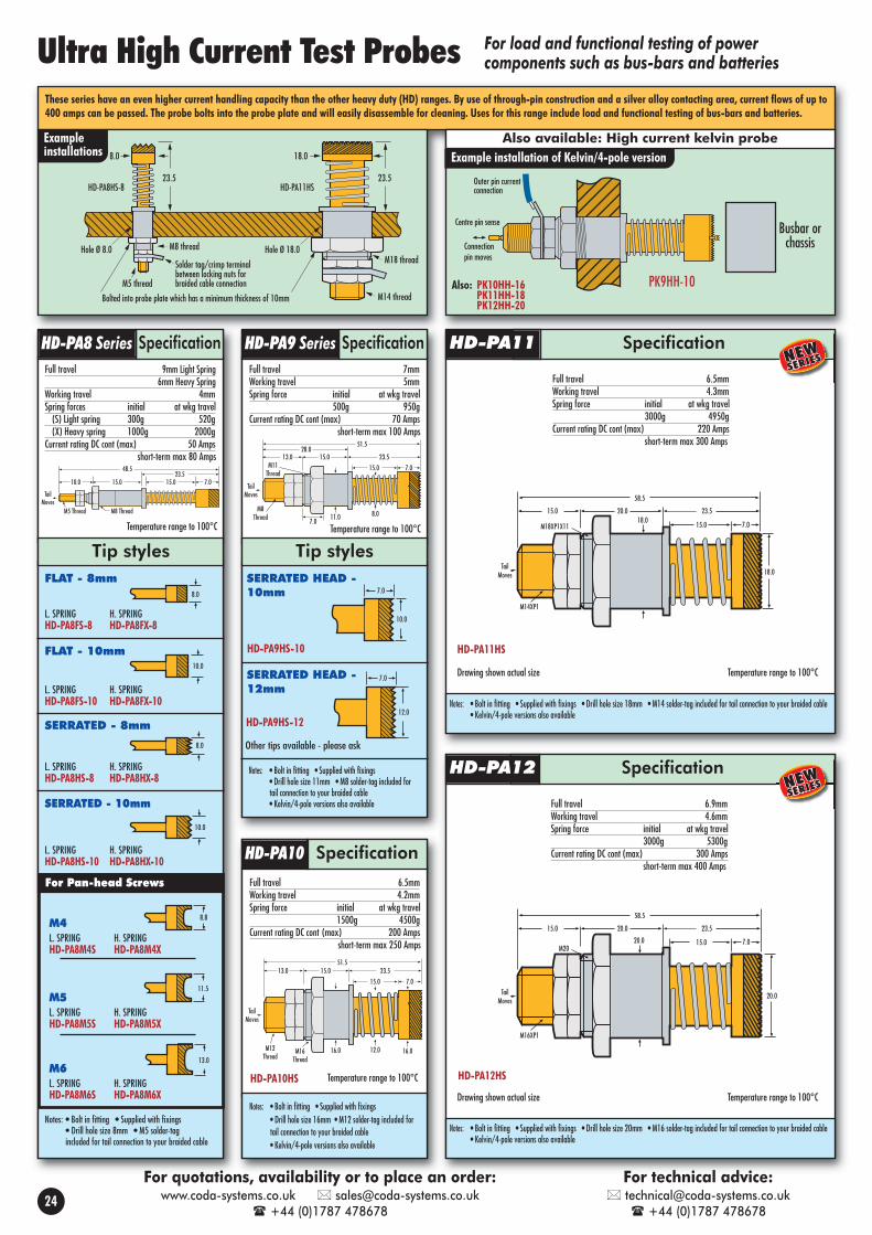
These series have an even higher current handling capacity than the other heavy duty (HD) ranges. By use of through-pin construction and a silver alloy contacting area, current flows of up to400 amps can be passed. The probe bolts into the probe plate and will easily disassemble for cleaning. Uses for this range include load and functional testing of bus-bars and batteries.
7.015.015.010.023.5
48.5
M8 ThreadM5 Thread
TailMoves
15.0 7.0
23.515.013.0
51.5
TailMoves
28.0
11.07.0
M8Thread
M11Thread
8.0
Temperature range to 100°C
15.0 7.0
23.515.013.051.5
Actual size
M16Thread
M12Thread
TailMoves
12.016.0 16.0
Temperature range to 100°C
Temperature range to 100°C
For Pan-head Screws
Tip styles
L. SPRING H. SPRINGHD-PA8FS-8 HD-PA8FX-8
L. SPRING H. SPRINGHD-PA8FS-10 HD-PA8FX-10
SERRATED HEAD -12mm
7.0
12.0
HD-PA9HS-12
FLAT - 8mm
FLAT - 10mm
L. SPRING H. SPRINGHD-PA8HS-8 HD-PA8HX-8
L. SPRING H. SPRINGHD-PA8HS-10 HD-PA8HX-10
SERRATED - 8mm
SERRATED - 10mm
M4L. SPRING H. SPRINGHD-PA8M4S HD-PA8M4X
M5L. SPRING H. SPRINGHD-PA8M5S HD-PA8M5X
M6L. SPRING H. SPRINGHD-PA8M6S HD-PA8M6X
SERRATED HEAD -10mm 7.0
10.0
HD-PA9HS-10
HD-PA10HS
Other tips available - please ask
Notes: • Bolt in fitting • Supplied with fixings• Drill hole size 11mm • M8 solder-tag included for tail connection to your braided cable• Kelvin/4-pole versions also available
Notes: • Bolt in fitting • Supplied with fixings• Drill hole size 16mm • M12 solder-tag included for tail connection to your braided cable• Kelvin/4-pole versions also available
Notes: • Bolt in fitting • Supplied with fixings• Drill hole size 8mm • M5 solder-tag included for tail connection to your braided cable
8.0
10.0
8.0
10.0
8.8
11.5
13.0
Tip styles
Exampleinstallations
TailMoves
M14XP1
15.0 7.0
23.520.015.0
58.5
M18XP1X1118.0
18.0
Temperature range to 100°CDrawing shown actual size
Notes: • Bolt in fitting • Supplied with fixings • Drill hole size 18mm • M14 solder-tag included for tail connection to your braided cable• Kelvin/4-pole versions also available
PK9HH-10
Busbar orchassis
Outer pin currentconnection
Centre pin sense
Connectionpin moves
SpecificationHD-PA8 Series SpecificationHD-PA9 Series SpecificationHD-PA11
SpecificationHD-PA10
HD-PA11HS
Also: PK10HH-16PK11HH-18PK12HH-20
TailMoves
M16XP1
15.0 7.0
23.520.015.0
58.5
M2020.0
20.0
Temperature range to 100°CDrawing shown actual size
Notes: • Bolt in fitting • Supplied with fixings • Drill hole size 20mm • M16 solder-tag included for tail connection to your braided cable• Kelvin/4-pole versions also available
SpecificationHD-PA12
HD-PA12HS
M18 thread
M14 thread
23.5
18.0
HD-PA11HS
Hole Ø 18.0Hole Ø 8.0
M5 thread
M8 thread
Solder tag/crimp terminalbetween locking nuts forbraided cable connection
23.5
8.0
HD-PA8HS-8
Bolted into probe plate which has a minimum thickness of 10mm
Also available: High current kelvin probe
Ultra High Current Test Probes
Full travel 9mm Light Spring6mm Heavy Spring
Working travel 4mmSpring forces initial at wkg travel(S) Light spring 300g 520g(X) Heavy spring 1000g 2000g
Current rating DC cont (max) 50 Ampsshort-term max 80 Amps
Full travel 7mmWorking travel 5mmSpring force initial at wkg travel
500g 950gCurrent rating DC cont (max) 70 Amps
short-term max 100 Amps
Full travel 6.5mmWorking travel 4.2mmSpring force initial at wkg travel
1500g 4500gCurrent rating DC cont (max) 200 Amps
short-term max 250 Amps
For load and functional testing of powercomponents such as bus-bars and batteries
24
For quotations, availability or to place an order:www.coda-systems.co.uk [email protected]
+44 (0)1787 478678
For technical advice: [email protected]
+44 (0)1787 478678
Example installation of Kelvin/4-pole version
Full travel 6.5mmWorking travel 4.3mmSpring force initial at wkg travel
3000g 4950gCurrent rating DC cont (max) 220 Amps
short-term max 300 Amps
Full travel 6.9mmWorking travel 4.6mmSpring force initial at wkg travel
3000g 5300gCurrent rating DC cont (max) 300 Amps
short-term max 400 Amps
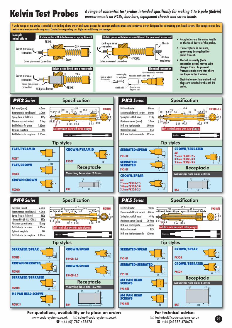
Connection area for probe outerConnection area for probe inner
Connector plugfor probe outer
Flexible cable
Connector plugfor probe innerCrimp or solder to
Flexible cable
• Receptacles are the same lengthas the fixed barrel of the probe.
• If a receptacle is not used,epoxy may be required forprobe fitment.
• The tail assembly (bothconnection areas) moves withplunger travel. To preventfractures make sure that thereare loops in the 2 cables.
• Electrical connection method - allplugs are included with each PKprobe.
44.5
Ø 4.2
22.520.010.06.04.0 14.0 7.0 2
Ø 5.0 Ø 2.0Ø 3.0Ø 1.5Ø 5.0
Ø 3.0
Full travel (outer) 7.0mmRecommended travel (outer) 4.0mmSpring force at full travel 460g- Except PK4QB-3.5, PK4M2J 250gMaximum current (outer) 10 AmpDrill hole size for probe 4.20mmOptional receptacle RK4Drill hole size for receptacle 4.80mm
45.5
Ø 5.7
22.520.010.06.04.0 14.0 7.0 3
Ø 6.5Ø 4.5Ø 1.5
8.88.2
Full travel (outer) 7.0mm
Recommended travel (outer) 4.0mm
Spring force at full travel 480g
Maximum current (outer) 20 Amp
Drill hole size for probe 5.70mm
Optional receptacle RK5
Drill hole size for receptacle 6.30mmActual size Actual size
RK3
Mounting hole size: 3.2mm
Receptacle
35.0
Ø 2.9
14.019.09.06.04.0 8.0 5.0 2
Ø 3.5 Ø 0.8Ø 2.0Ø 1.0Ø 3.5
Ø 2.0
Both terminals move with outer plunger.
Full travel (outer) 4.0mm
Recommended travel (outer) 3.0mm
Spring force at full travel 210g
Maximum current (outer) 5 Amp
Drill hole size for probe 2.90mm
Optional receptacle RK3
Drill hole size for receptacle 3.25mm
RK2
Mounting hole size: 2.0mm
Receptacle
9.0
2.0
2.3
0.2
9.0
3.2
3.5
0.1
10.0
4.7
5.5
0.2
7.0
35.0
Ø 1.65
14.019.09.06.04.0 10.9 3.0 2
Ø 1.8 Ø 0.6Ø 1.5Ø 0.8Ø 1.8
Ø 1.1
Tip styles Tip styles
Both terminals move with outer plunger.
Both terminals move with outer plunger. Both terminals move with outer plunger.
SERRATED/SPEAR
PK3HB
CROWN/SPEARAØ2.5mm PK3QB-2.53.0mm PK3QB-3.03.5mm PK3QB-3.5
CROWN/SERRATEDAØ2.5mm PK3QH-2.53.0mm PK3QH-3.03.5mm PK3QH-3.5
FLAT/CROWN
PK2FQ
CROWN/CROWN
PK2QQ
FLAT/PYRAMID
PK2FT
CROWN/PYRAMID
PK2QT3.0 2.0
A 2.0
A 1.0Ø 1.8
1.8
1.8
Full travel (outer) 4.5mm
Recommended travel (outer) 3.0mm
Spring force at full travel 195g
Maximum current (outer) 3 Amp
Drill hole size for probe 1.65mm
Optional receptacle RK2
Drill hole size for receptacle 2.05mm
1.8
RK4
Mounting hole size: 4.7mm
Receptacle
Tip styles Tip styles
SpecificationPK2 Series
SpecificationPK4 Series SpecificationPK5 Series
SpecificationPK3 Series
SERRATED/SPEAR
PK4QH
CROWN/SPEAR
PK4QB-3.5
CROWN/SPEAR
PK4QB-5.0
PK4HB
CROWN/SERRATED5.0
2.0
6.02.0
3.52.0
5.02.0
SERRATED/SERRATED
PK4HH
PK4HH PK5M4J
PK2QQ PK3QB-3.5
M2 PAN HEAD SCREWS
PK4M2J
5.02.0
Mounting hole size: 6.2mm
Receptacle
SERRATED/SPEAR
PK5QB
SERRATED/SERRATED
PK5HHPK5QH
PK5HB
CROWN/SPEAR
PK5M3J
M4 PAN HEAD SCREWS
6.02.0
6.02.0
6.02.0 6.0
2.0
PK5M4J
7.0
8.8
CROWN/SERRATED
Actual size Actual size
10.0
6.2
7.0
0.2
RK5
M3 PAN HEAD SCREWS
PK4HB
25.4Centre pin sense
connection
Outer pin current connection
24.6
PK4HB
PK5M3J M3 Panhead screw
ChassisCentre pin senseconnection
Outer pin current connectionEpoxy
Outer pin currentconnection RK4 press-fitment
Centre pin senseconnection
PK4HB
25.4Centre pin sense
connection
Outer pin current connection
24.6
PK4HB
PK5M3J M3 Panhead screw
ChassisCentre pin senseconnection
Outer pin current connectionEpoxy
Outer pin currentconnection RK4 press-fitment
Centre pin senseconnection
PK4HB
25.4Centre pin sense
connection
Outer pin current connection
24.6
PK4HB
PK5M3J M3 Panhead screw
ChassisCentre pin senseconnection
Outer pin current connectionEpoxy
Outer pin currentconnection RK4 press-fitment
Centre pin senseconnection
Exampleinstallations
A wide range of tip styles is available including sharp inner and outer probes for contact problem areas and concaved outer designed for contacting pan-head screws. This range makes lowresistance measurements very easy. Contact us regarding our high current/heavy duty range.
Kelvin Test Probes A range of concentric test probes intended specifically for making 4 to 6 pole (Kelvin)measurements on PCBs, bus-bars, equipment chassis and screw heads
SERRATED/SERRATEDPK3HH 3.0 1.0
25
Kelvin probe with interference or epoxy fitment Kelvin probe with interference fitment for pan head screw test
Electrical connectionKelvin probe fitted into a receptacle
For quotations, availability or to place an order:www.coda-systems.co.uk [email protected]
+44 (0)1787 478678
For technical advice: [email protected]
+44 (0)1787 478678

Kelvin Test Pins
Transformer Test Fixture Kits
SMD Component Test Fixture
SpecificationLead diameter range: 0.5mm - 0.8mmMinimum test centre spacing: 2.54mmMaterial: Gold plated beryllium copperOverall length: 26.3mm
SpecificationLead diameter range: 0.8mm - 1.3mmMinimum test centre spacing: 3.75mmMaterial: Gold plated beryllium copperOverall length: 26.0mm
Small socket pin Large socket pin
KWP100 KWP150
Kelvin Test Pins & Fixture Kits Kelvin test pins, modules and fixture kits for the testing oftransformers, chokes, relays, solenoids and cable harnesses
3.4
26.0
2.1
26.3
A brand new solution to the fast testing ofmany configurations of SMD woundcomponents.
KWF100 Small transformer fixture kit KWF150 Large transformer fixture kit
Actual sizeActual size
A twin-terminal socket pin providing atwo point contact onto a single lead,
pin or terminal. This method allows a high quality and effective4-pole/kelvin connection, and with suitable equipmentattached, will enable the taking of accurate resistance andimpedance measurements.
Available in two sizes, the openconstruction and the simplefitment method of this rangeallows quick installation into yourtest block. The high quality ofmaterials used in manufacturingthis product range allowsdurability and a reliable testcontact for a wide range ofcomponent lead diameters,typically 0.5mm to 1.3mm.Fitment instructions are availableon our website www.coda-systems.co.uk
Top view
Example installation
Incorporating KWP kelvinpins (shown above), this
series is suitable for use with Voltech’s UniversalFixture and for standalone testing. Each kit is idealfor users that have the facilities to customise theirown test fixtures. The kit of parts include enoughKWP kelvin pins to test wound components with upto 10 pins. Full customising instructions areavailable on www.coda-systems.co.uk
Kit contains:• 1 x socket blank plate• Spacer blocks• Velcro fixing strips• 1 x G11 lead guide (increases
life of socket blank plate)• 10 x KWP kelvin pins• 1 x drill template, all fixings
and full instructions
Customised KWF100 small transformer test jig
Finished KWF100 jig with small transformer under test. This type of jig can be built to yourrequirements, please contact us with your specific enquiry.
Customised KWF150 large transformer test jig
Finished KWF150 jig with larger transformer under test. This type of jig can be built to yourrequirements, please contact us with your specific enquiry.
KWC jig with transformer clamped in place.Typical KWC jig for testing SMT transformers.
This range of jigs feature:• Zero insertion force connection which eliminates lead bending.• Every lead has two separate connections which allows a kelvin test, if
required• Locking lever system prevents the component under test jumping out.
The simplicity of the jig allows for a reduced handling time when open• A pneumatically operated version is available as an option, please ask
about this
This type of jig is built to your unique requirements. Please contact us withyour specific enquiry.
KWP Series
KWF Series
KWC Series
26
For quotations, availability or to place an order:www.coda-systems.co.uk [email protected]
+44 (0)1787 478678
For technical advice: [email protected]
+44 (0)1787 478678
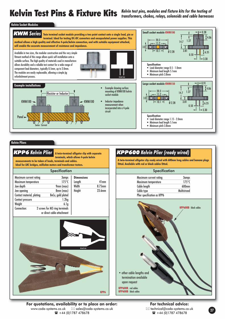
Kelvin Pliers
A twin-terminal alligator clip with separateterminals, which allows 4-pole kelvin
measurements to be taken of leads, terminals and cables.Ideal for LRC bridges, milliohm meters and transformer testers.
A twin-terminal alligator clip ready wired with 600mm long cables and banana plugsfitted. Available with red or black cables fitted.
Actual size
Kelvin Test Pins & Fixture Kits Kelvin test pins, modules and fixture kits for the testing oftransformers, chokes, relays, solenoids and cable harnesses
Kelvin Socket Modules
Twin terminal socket module providing a two point contact onto a single lead, pin orterminal. Ideal for testing DC-DC converters and encapsulated power supplies. This
method allows a high quality and effective 4-pole/kelvin connection, and with suitable equipment attached,will enable the accurate measurement of resistance and impedance.
Example installations• Example showing surface
mounting of KWM100 kelvinsocket module
• Inductor impedancemeasurement whenincorporated into a 4-polecircuit
Resistor or Inductor
KWM100KWM100
Panel
Sense Current
Available in two sizes, the modular construction and the very simplefitment method of this range allows quick self-installation onto asuitable surface. The high quality of materials used in manufactureallows durability and a reliable test contact for a wide range ofcomponent lead diameters, typically 0.5mm, up to 2.0mm.The modules are easily replaceable, allowing a simple jigrefurbishment process.
0.38
4.061.27
3.81
14.7
0.503.30
6.3510.13.81
15.220.3
Ø 2.28
Actual size
Specification• Lead diameter range 0.5 - 1.0mm• Minimum lead length 5.1mm• Minimum pitch 3.8mm
0.38
4.061.27
3.81
14.7
0.503.30
6.3510.13.81
15.220.3
Ø 2.28
Small socket module KWM100
0.38
4.061.27
3.81
14.7
0.503.30
6.3510.13.81
15.220.3
Ø 2.28
Specification• Lead diameter range 1.15 - 2.0mm• Minimum lead length 5.1mm• Minimum pitch 3.8mm
0.91
4.061.27
3.81
14.7
0.503.30
6.3510.13.81
15.220.3
Ø 2.28
Large socket module KWM150
Specification Specification
Maximum current rating 3ampsMaximum temperature 175°CJaw depth 9mm (max)Jaw opening 8mm (max)Contact material, plating BeCu, gold platedContact pressure 1.2kgWeight 6.1gConnection: 2 screws for M3 ring terminals
or direct cable attachment
Maximum current rating 3ampsMaximum temperature 175°CCable length 600mmCable type MultistrandPlier specification as KPP6
DimensionsLength 41mmWidth 8.75mmHeight 23.6mm
• other cable lengths andtermination availableupon request
KWM Series
KPP6 Kelvin Plier KPP600 Kelvin Plier (ready wired)
27
For quotations, availability or to place an order:www.coda-systems.co.uk [email protected]
+44 (0)1787 478678
For technical advice: [email protected]
+44 (0)1787 478678
KPP6KPP600R - red cablesKPP600B - black cables
KPP600B - black cables

SpecificationMounting hole size: 6.35/6.40mm press fitment
Drill Part No: DE3
Ø 3.8
4.5
Ø 5.0
4.513.0
31.5Jack for cable/plug assembly
(RP8-W70 or MCX plug
CONCAVE CENTRE PROBE PE3GSPEAR CENTRE PROBE PE3B
27.7620.321.09 1.52
0.76 Full travel6.35
6.863.68 6.48 6.35 5.841.02
Concavetip PE3G
SMBjack
Outer
Inner probe
5.59Typ.
2.92Typ.
Mountinghole
12.7Typ.
1.91Typ.
8.64Typ.
Ø 1.18
5.08Typ.
Ref
7.49
38.99
31.12
Mates with standard SMAR.F. connector
29.46Typ.
Compression6.35
Outer
Inner probe
5.59Typ.
2.92Typ.
Mountinghole
12.7Typ.
1.91Typ.
8.64Typ.
Ø 1.18
5.08Typ.
Ref
7.49
38.99
31.12
Mates with standard SMAR.F. connector
29.46Typ.
Compression6.35
Notes:• Other tipstyles can be fitted
• 3.2mm centre version available
Top view
MCX plug with 70cm RG178 cableattached, the cable end is unterminated
Notes:• Two tipstyles • Short overall length
Side view (PE6KH)
10.16Typ.
4.01
2.544.06
17.02
26.54
7.87
Mates with standard SMA R.F. connector
2.54
4.0010.00Typ.
2.66Typ.
14.00 Typ.1.30 Typ.
Mounting hole
3.05 Typ.
7.89Typ.
Inner
Holes forextra
probes
Outer
7.49
29.6
0
3.05 Typ.
7.89Typ.
Inner
Holes forextra
probes
Outer
7.49
29.6
0
Notes:• Other tipstyles can be fitted• 4 outer probe positions allow several configurations
• Probe configuration can be changed
Top view
Tiponlyshown
Tiponlyshown
• variants available
Tiponlyshown
Tiponlyshown
Tiponlyshown
Side view
Side view
Top view (PE6KH)
FOR PCB TEST - A series of superior performance RF coaxial test probesdesigned to allow an instrumentation-quality interface for broadband RF
measurements up to 4GHz. Accurate small signal and RF power (up to 50w) measurements makethem ideal for cellular telephone testing applications.
Example installations
Specification
Configurations
Impedance 50 OhmsWorking travel (except PE6KH/KB) 4.24mmSpring force at working travelEach probe (3) 143gCurrent rating DC cont (max) 3 Amps
Maximum frequency 4GHzVSWR 1.15:1@1GHz, 1.11:1 typicalInsertion loss 0.12:dB@1GHzMinimum return loss 23db, 26db typicalRequired tail connector SMA plug
COAXIAL RF INTERFACING PAIR - The PE3 is a coaxial probe and landdesigned to be a spring-loaded high frequency mating pair.
Impedance 50 Ohms
Working travel 4.24mm
Spring force at working travel g
Outer shield 57g
Inner contact 113g
Current rating DC cont (max) 3 Amps
Maximum frequency (3dB c/o) 2.5GHz
VSWR 1.15:1@1GHz
Insertion loss 0.13:dB@1GHz
Required tail connector SMB plug
For use as a spring loaded test probe for all of the common radio frequencyconnectors, this will remove the need to use sacrificial plugs. Contact us if
your connector type is not shown.
Impedance 50 OhmsWorking travel 4mmSpring force at working travel 530gMaximum frequency (3dB c/o) 2GHz
Ask if 4GHz is requiredRequired tail connector MCX
6.35
Press ring6.48 DIA
6.868.89
13.33
SMBjack
6.30
Coaxial landCoaxial probe
Tip styles
PCB testing to4GHz (50Ω)
RF connectortest to 2GHz(50Ω)
RF coaxial interfaceto 2.5GHz (50Ω)
PE8SMB
SpecificationMounting hole size without receptacle: 4.5mm
Mounting hole size with receptacle: see in each receptacle type
SMB PLUG
PRESS-FITMENT
Ø 3.8
Ø 5.0
4.5
22.00.4
Ø 5.3 Ø 5.0
Ø 5.0
4.0 12.0
Receptacles
RE8 Mounting hole size 4.98mm - 4.99mm
CABLE & PLUG ASSEMBLYFOR PE8 SERIES
RP8-W70
Replacement centre probesCONCAVE PE3-RG SPEAR PE3-RB
High Frequency Test Probes
PE8SMB
Tip styles
PE3L
LINEAR CONFIGURATION: 5mm centres
ISOSCELES CONFIGURATION: 4mm centres
QUADRATURE CONFIGURATION: 3mm centres
Part number Spare probe
PE6KL PE6QS
Part number Spare probe
PE6KQG PE6QS
Part number Height Description Spare probe
PE6KB 6.14mm Spear PE6HB
PE6KH 4.06mm Serrated PE6HH
Tiponlyshown
PE3 Series
PE6 Series PE8 Series
28
For quotations, availability or to place an order:www.coda-systems.co.uk [email protected]
+44 (0)1787 478678
For technical advice: [email protected]
+44 (0)1787 478678
Test probes with a broad bandwidth for making highfrequency tests of RF connectors and PCBs
PE6KL
Centre
Gnd
Gnd
PCB
SMB jackfor cableassembly
PE3G PE3LSMB jackfor cableassembly
50½Interfacing pair
Receptacleallows somesidewaysmovement toaid alignment
RE8-SW
PE8NT
N-Typeconnector
Equipmentpanel
PE6KL
Centre
Gnd
Gnd
PCB
SMB jackfor cableassembly
PE3G PE3LSMB jackfor cableassembly
50½Interfacing pair
Receptacleallows somesidewaysmovement toaid alignment
RE8-SW
PE8NT
N-Typeconnector
Equipmentpanel
PE6KL
Centre
Gnd
Gnd
PCB
SMB jackfor cableassembly
PE3G PE3LSMB jackfor cableassembly
50½Interfacing pair
Receptacleallows somesidewaysmovement toaid alignment
RE8-SW
PE8NT
N-Typeconnector
Equipmentpanel
4.74.0
14.02.5
1.8
5.5
8.0
PE8NT
N-TYPE SOCKET
1.58.08.5
22.0
PRESS-FITMENTAllows some sideways movement for mis-aligned targets
RE8-SW Mounting hole size 7.98mm - 7.99mm
4.74.0
11.54.0
2.43.1
1.86.0
SMA JACK
PE8SMA
MCX JACK
4.74.0
0.8
5.3
8.0
1.012.5
PE8MCX
MMCX JACK
4.74.02.21.8
1.20.8
11.5
PE8MMCX
SMC PLUG
4.74.0
11.50.1
1.5
3.85.0
PE8SMC
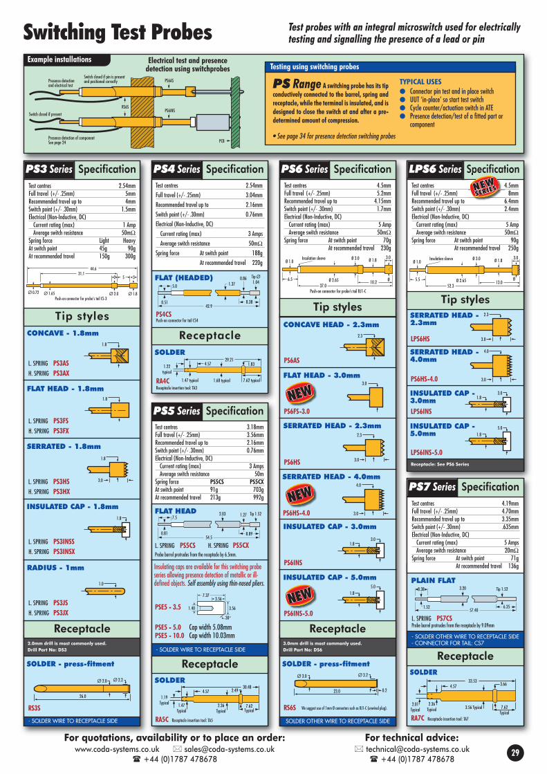
Presence detectionand electrical test
PS6AS
Presence detection of componentSee page 24
PS6INSSwitch closed if present
RS6S
Switch closed if pin is presentand positioned correctly
PCB
54.5
7.52.03 1.27
8.89
Tip 1.52
0.81
FLAT HEAD
- SOLDER WIRE TO RECEPTACLE SIDE
Receptacle
Probe barrel protrudes from the receptacle by 6.5mm.
L. SPRING PS5CS
PSE5 - 3.5
PSE5 - 5.0 Cap width 5.08mmPSE5 - 10.0 Cap width 10.03mm
H. SPRING PS5CX
Insulating caps are available for this switching probeseries allowing presence detection of metallic or ill-defined objects. Self assembly using thin-nosed pliers.
3.56
1.40
7.37
3.56
30°
SpecificationPS5 SeriesSERRATED HEAD - 2.3mm
PS6HS
CONCAVE HEAD - 2.3mm
PS6AS
INSULATED CAP - 3.0mm
PS6INS
RS6S
Ø 3.2Ø 3.0
23.0 0.2
3.01.8
2.3
2.3
3.0
We suggest use of 1mm Ø connectors such as RJ1-C (unwired plug).
SOLDER OTHER WIRE TO RECEPTACLE SIDE
Example installations
PS Range A switching probe has its tipconductively connected to the barrel, spring andreceptacle, while the terminal is insulated, and isdesigned to close the switch at and after a pre-determined amount of compression.
TYPICAL USES Connector pin test and in place switch UUT ‘in-place’ so start test switch Cycle counter/actuation switch in ATE Presence detection/test of a fitted part or
component
44.631.1
2 5 3
Ø 0.72 Ø 1.65 Ø 2.0 Ø 1.8Push-on connector for probe’s tail CS-3
Tip styles
Ø 1.0
6.510.2
3.0
Ø
Ø 3.0
Ø 2.65
Ø 1.8Insulation sleeve
37.0Push-on connector for probe’s tail RJ1-C
SERRATED - 1.8mm
FLAT HEAD - 1.8mm
RADIUS - 1mm
INSULATED CAP - 1.8mm
SOLDER - press-fitment SOLDER - press-fitment
L. SPRING PS3INSSH. SPRING PS3INSX
L. SPRING PS3JSH. SPRING PS3JX
L. SPRING PS3FSH. SPRING PS3FX
RS3S
1.8
3.0
1.8
1.0
1.8
Ø 2.2Ø 2.0
26.0
L. SPRING PS3HSH. SPRING PS3HX
CONCAVE - 1.8mm1.8
L. SPRING PS3ASH. SPRING PS3AX
PS4CSPush-on connector for tail CS4
8.3842.9
5.0 1.370.86 Tip Ø
1.04
0.51
FLAT (HEADED)
Receptacle
2.0mm drill is most commonly used.Drill Part No: DS3
Receptacle3.0mm drill is most commonly used.Drill Part No: DS6
Receptacle
Testing using switching probes
- SOLDER WIRE TO RECEPTACLE SIDE
Electrical test and presencedetection using switchprobes
• See page 34 for presence detection switching probes
Tip styles
SpecificationPS6 Series SpecificationLPS6 SeriesSpecificationPS4 SeriesSpecificationPS3 Series
SOLDER
RA5C Receptacle insertion tool: TA5
30.48
1.19Typical 1.47
Typical2.36
Typical7.62
Typical
4.57 2.49
SOLDER
RA4CReceptacle insertion tool: TA3
29.214.571.22
typical
1.47 typical 1.68 typical 7.62 typical
1.83
PLAIN FLAT
L. SPRING PS7CS
8.38 3.20 Tip 1.52
1.5257.40
6.35
SpecificationPS7 Series
SOLDER
RA7C Receptacle insertion tool: TA7
33.534.57
2.01Typical 3.56 Typical 7.62
Typical
2.36Typical
3.66
Probe barrel protrudes from the receptacle by 9.09mm
- SOLDER OTHER WIRE TO RECEPTACLE SIDE- CONNECTOR FOR TAIL: CS7
Receptacle
Switching Test Probes
INSULATED CAP - 5.0mm
LPS6INS-5.0
5.01.8
Ø 1.0
5.513.0
3.0
Ø
Ø 3.0
Ø 2.65
Ø 1.8Insulation sleeve
52.3
Tip stylesSERRATED HEAD - 2.3mm
LPS6HS
2.3
3.0
SERRATED HEAD - 4.0mm
PS6HS-4.0
4.0
3.0
INSULATED CAP -3.0mmLPS6INS
3.01.8
Receptacle: See PS6 Series
Test centres 2.54mmFull travel (+/- .25mm) 5mmRecommended travel up to 4mmSwitch point (+/- .30mm) 1.5mmElectrical (Non-Inductive, DC)Current rating (max) 1 AmpAverage switch resistance 50mΩ
Spring force Light HeavyAt switch point 45g 90gAt recommended travel 150g 300g
Test centres 4.5mmFull travel (+/- .25mm) 8mmRecommended travel up to 6.4mmSwitch point (+/- .30mm) 2.4mmElectrical (Non-Inductive, DC) Current rating (max) 5 AmpAverage switch resistance 50mΩ
Spring force At switch point 90gAt recommended travel 250g
Test centres 4.5mmFull travel (+/- .25mm) 5.2mmRecommended travel up to 4.15mmSwitch point (+/- .30mm) 1.7mmElectrical (Non-Inductive, DC) Current rating (max) 5 AmpAverage switch resistance 50mΩ
Spring force At switch point 70gAt recommended travel 230g
Test centres 2.54mmFull travel (+/- .25mm) 3.04mm Recommended travel up to 2.16mmSwitch point (+/- .30mm) 0.76mmElectrical (Non-Inductive, DC) Current rating (max) 3 Amps Average switch resistance 50mΩ
Spring force At switch point 188gAt recommended travel 220g
Test centres 3.18mmFull travel (+/- .25mm) 3.56mm Recommended travel up to 2.16mmSwitch point (+/- .30mm) 0.76mmElectrical (Non-Inductive, DC) Current rating (max) 3 Amps Average switch resistance 50m
Spring force PS5CS PS5CXAt switch point 91g 703gAt recommended travel 213g 992g
Test centres 4.19mmFull travel (+/- .25mm) 4.70mmRecommended travel up to 3.35mmSwitch point (+/- .30mm) .635mmElectrical (Non-Inductive, DC) Current rating (max) 5 AmpsAverage switch resistance 20mΩ
Spring force At switch point 71gAt recommended travel 136g
29
For quotations, availability or to place an order:www.coda-systems.co.uk [email protected]
+44 (0)1787 478678
For technical advice: [email protected]
+44 (0)1787 478678
Test probes with an integral microswitch used for electricallytesting and signalling the presence of a lead or pin
FLAT HEAD - 3.0mm
PS6FS-3.0
3.0
SERRATED HEAD - 4.0mm
PS6HS-4.0
4.0
3.0
INSULATED CAP - 5.0mm5.0
1.8
PS6INS-5.0

Pneumatically Controlled Probing Systems
A PR
TT
APR
TT AP
RT
T
Filtered6 BAR/86psi
air Inlet
AH-33mm Hose
AM3-3
CB-1AM3-3
12VDC switchedsupplySwitch 1
EV12 R
P
ACB-2
Switch 3Switch 2AH-3 3mm Hose
AH-33mm Hose R
AM5-3
Man2-0
AM5-3AM5-3 P
A
AH-3 3mm Hose
AM5-3
AM5-2
AH-33mm Hose
AI-G1 - 8-3
AH-22mm Hose
4 x AM5-1
AH-1 1mm Hose
AI-G1 - 8-M5AH-1 1mm Hose
Airline foruse elsewhere AM5-1
6 x AM5-0
Man10-0
AH-11mm Hose
Man2-3 - 1
AH-11mm Hose
Electricalconnectionto probe
ECP4
HR2-13 x AM5-0
AI-G1 - 8-3
7 x AM5-1
AI-G1 - 8-0
Man10-0
1 2 3 4 5 6 7 8 9 10 11 12 13Probes
A
AM3-3
T-piece manifold
10-way manifold
PP4BSPP4BS
ECP4
PP5QS
Pneumatic test probes provide an alternative to the use of conventional spring contact testprobes to solve some problems in test fixture design. The major features of pneumaticprobing systems are:• There is no need for a moving probe plate or push plate.• The probes are held away from the test item until contact is required, which avoids
damage and wear and tear on the probe tips. When the compressed air is switched onto the probe the tip moves into contact with the test pad.
• The ability to program sequential tests using a programmer and electric valves tooperate different probes at set times in the test program.
An important consideration is that probes not in use are not in contact with the item undertest and so cannot introduce measurement errors by adding any erroneous circuit paths.Below is a complete range of probes, together with all the hoses, terminations, manifoldsfor air distribution, and electric switches for programming a test routine. Please note, this isa hypothetical set up to show all the components in use.
MAN10-0 distributes air
to probes 1 to 7
3
MAN10-0distributes air toprobes 10 to 13
8
MAN2-3-1distributes air toprobes 8 and 9
7
Air at CB-2 is held by
switches 2 and 3
5
By program control:
Switch 2 is operated
releasing air to MAN2-3-1
Switch 3 releases air to
manifold MAN10-0
6
MAN2-0 splits air into
two paths
2
Probe tips rise to
operating position
4
At start up,switch 1releases air tomanifold 2-0
1
Pneumatic system components
ManifoldsThese pressure chambers have a single air inlet and aseparate air outlet for each device that is to be operated.
Coda part no. Description
MAN2-0A 2-way manifold, supplied with 3 x M5 threaded holes sothat you can fit your choice of AM5 series connectors.
MAN2-3-1A MAN2-0 supplied fitted with 3 x AM5-1 connectors for usewith AH-1 1mm hose
MAN2-3-2A MAN2-0 supplied with 3 x AM5-2 connectors for use withAH-2 2mm hose
MAN10-0
A 10-way manifold supplied with 10 x M5 threadedholes for connectors; AM5-1 for 1mm output or blankingplug AM5-0. The air input uses either AI-GI-8.3 for 3mmhose or AI-GI-8-M5 for AM5 connectors.
Connectorbases
Connector base port markings: P = Input, A = Output, R = Exhaust
Coda partno. Description
CB-1Single connector base for a single electricvalve. Uses AM3 series connectors.
CB-2 toCB-10
Multiple connector base for muliples of electricair valves. Uses AM5 series connectors.
Electric airvalves
The EV12 and EV24 are for 12V and 24Voperation respectively, which allow theswitching of the air supply. They must beused in conjunction with one of theconnector bases as shown above.
Coda part no. Description
EV12 Electric valve: 12V DC operation
EV24 Electric valve: 24V DC operation
Hose connectorsfor CB-1 manifold
These allow hose connections tobe made to connector bases.
Coda part no. Description
AM3-1 An M3 to 1mm hose connector
AM3-2 An M3 to 2mm hose connector
AM3-3 An M3 to 3mm hose connector
Hose connectorsfor all except CB-1
These allow hose connections tobe made to manifolds.
Coda part no. Description
AM5-0 An M5 blanking plug
AM5-1 An M5 to 1mm hose connector
AM5-2 An M5 to 2mm hose connector
AM5-3 An M5 to 3mm hose connector
AI-G1-8-3 Air inlet connector for 3mm hose
AI-G1-8-M5 Air inlet connector for M5 connection
AI-G1-8-0 Air inlet blanking plug
Hose reducersThese allow different sizes of air hose to be connectedtogether.
Coda part no. Description
HR2-1 A 2mm to 1mm reducer
HR3-1 A 3mm to 1mm reducer
HR3-2 A 3mm to 2mm reducer
30
For quotations, availability or to place an order:www.coda-systems.co.uk [email protected]
+44 (0)1787 478678
For technical advice: [email protected]
+44 (0)1787 478678

Pneumatically Controlled Probing Systems
ECP4
Electrical connectionwith clip
Air hose
PP4BS Up to20mm
PP6QS
RP4Direct electricalconnection to receptacle allowsprobe to be changed withoutdisconnecting electrical cable
Air hose
Up to10mm
PP4BSactivated
RP6
Direct electricalconnection to receptacle allowsprobe to be changed withoutdisconnecting electrical cable
Air hose
Example installations
PP2TS-040
PP2QS-040
RP2
40.07.0 5.5
ø 1.7ø 1.5Hose fitting area
Actual size Mounting hole size 1.5mm
1.0
27.511.0 0.4
ø 2.0ø 1.8Drill hole size 1.8mm
4 POINT LARGE CROWN
PP2QS-020
0.5
4 POINT SMALL CROWN
DAGGER
Receptacle & Terminations
Receptacle
ELECTRICALCLIP
RECEPTACLE
PP4TS-040
PP4BS
PP4QS
PP4TS-080
PP4HS
PP4AS
PP4JS
RP4
ECP4
ø 1.50
1.30
2.00
2.50
2.00
1.00
3.0
8.0
27.510.6 0.4
Drill hole size 3.0mm
CONCAVE
SERRATED
DOME
4 POINT CROWN
DAGGER
PYRAMIDHEAD
SPEARPOINT
solder wire ontoelectrical clipsolder cable to receptacle
Specification
42.79.7 5.5
ø 2.3ø 2.2Connector areaHose fitting area
Tip stylesTip styles
RECEPTACLE
PP5FS
PP5QS
PP5BS
RP5
54.49.7 5.5
ø 3.2ø 3.0Connector areaHose fitting area
39.210.6 0.4
Mounting hole size 3.4mm
ELECTRICAL CLIP
ECP43.0
8.0
SPEAR POINT
FLAT HEAD - 2.5mm
4 POINT CROWN HEAD
2.0
2.50
2.0
solder wire to the side or use electrical cliponto probe
solder wire onto electrical clip
RECEPTACLE
PP6BS
RP6
54.49.7 5.5
ø 4.2ø 4.0Connector areaHose fitting area
39.210.6 0.4
Mounting hole size 4.5mm
ELECTRICAL CLIP
ECP43.0
8.0
SPEAR POINT
solder wire to the side or use electrical cliponto probe
SpecificationSpecification Specification
RECEPTACLE
Actual size Mounting hole size 2.2mm
Actu
al siz
e Mo
untin
g hole
size
3.0
mm
Receptacle & Terminations Receptacle & Terminations
Tip styles Tip styles
PP6HS 2.50PP5HS
SERRATED - 2.5mm
2.50
PP6QS
4 POINT CROWN HEAD
2.0
Without receptacle With receptacle With receptacle
solder wire onto electrical clip
Minimum test centres:Without receptacle 4.5mmWith receptacle 5.0mm
Full travel 20.0mmWorking travel up to 12mmContact voice at working travel 420g
except PP6 BS 370gCurrent rating DC cont (max) 2 AmpsMaximum test operating temperature 90°CHose: use AH-1Connector: use ECP4Compressed air specification: Filtered, oil-free at recommended pressure of 6 bar
Minimum test centres:Without receptacle 2.54mmWith receptacle 3.50mm
Full travel 10.0mmWorking travel up to 6.0mmContact force at working travel 80gCurrent rating DC cont (max) 2 AmpsMaximum test operating temperature 90°CHose: use AH-1Connector: use ECP4Compressed air specification: Filtered, oil-free at recommended pressure of 6 bar
Pneumatically Operated Test Probes
31
Pneumaticallyoperated test
probes with a wide range of tip stylesto suit most applications.
Minimum test centres:Without receptacle 3.5mmWith receptacle 4.0mm
Full travel 20.0mmWorking travel up to 12mmContact voice at working travel 170gCurrent rating DC cont (max) 2 AmpsMaximum test operating temperature 90°CHose: use AH-1Connector: use ECP4Compressed air specification: Filtered, oil-free at recommendedpressure of 6 bar
Minimum test centres:Without receptacle 1.91mmWith receptacle 2.54mm
Full travel 10.0mmWorking travel up to 6.0mmContact force at working travel 80gCurrent rating DC cont (max) 2 AmpsMaximum test operating temperature 90°CHose: use AH-1Connection: SolderCompressed air specification:Filtered, oil-free at recommended pressure of 6 bar
PP6FS
SERRATED - 2.5mm
2.0
PP4 Series Large pneumatictest probes with
a high spring force and an extra longstroke for use in difficult test areas,such as recessed test points.
PP6 Series
For quotations, availability or to place an order:www.coda-systems.co.uk [email protected]
+44 (0)1787 478678
For technical advice: [email protected]
+44 (0)1787 478678
A system where the tip of the test probe is moved by compressed air negatingthe need to move the probe plate or the unit towards the probe field
Pneumaticallyoperated test
probes with a wide range of tip stylesto suit most applications.
PP2 Series Medium-sizedpneumatic test
probes with a medium spring force andan extra long stroke for use in difficulttest areas, such as recessed test points.
PP5 Series
Actu
al siz
e Mo
untin
g hole
size
4.0
mm
FLAT HEAD - 2.5mm
2.50
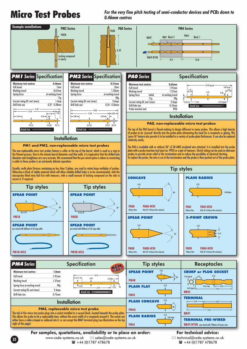
6.35
PA0B
Block 2 Block 1
9.9 10.8
PM4JPM2B
Locking compoundor epoxy
RM4T
RM4T-W700
RM4
ReceptaclesCRIMP or PLUG SOCKET
RM4C
TERMINAL
RM4T
4.57
0.69 Typical
0.56 Typical 0.76
Press ring9.91
4.45
3.18
9.91
6.35
Minimum test centres 1.0mm
Full travel 1.91mm
Working travel 1.27mm
Spring force at working travel 49g
Current rating DC cont (max) 2 Amps
Drill hole size 0.75mm
Installation
Specification
Example installations
Tip styles
SpecificationPM1 Series
Tip styles
16.5015.50
4.501.50
0.20
1.00
fl 0.25 fl 0.30 fl 0.15
Actual size
19.0017.00
2.80 0.502.00
Ø 0.32 Ø 0.37 Ø 0.21
Actual size
0.33 I.D.
0.51
0.25 Typical
19.05 Typical
0.45
Full Travel1.911.52
0.58
Actual size
PM4, replaceable micro test probeThe tail of this micro test probe plugs into a socket installed in a second block, located beneath the probe plate.This allows the probe to be a replaceable item, without the extra width of a receptacle around it. The socket caneither have a cable crimped or soldered into it, or can accept the RM4T terminal plug (see illustration on the topright of this page).
SPEAR POINT
PM1B
SPEAR POINTpre-wired with 600mm of 33 awg cable
30°
Ø 0.15
PM1B-W33
SPEAR POINT
PM2B
SPEAR POINTpre-wired with 800mm of 33 awg cable
PM2B-W33
CONCAVE
PA0A PA0A-W30 Without Wire With 30" (762mm) Wire Attached
SPEAR POINT
PA0B PA0B-W30 Without Wire With 30" (762mm) Wire Attached
90°
0.25
30°
0.25
PLAIN RADIUS
PA0J PA0J-W30Without Wire With 30" (762mm) Wire Attached
3-POINT CROWN
PA0U PA0U-W30Without Wire With 30" (762mm) Wire Attached
Full Radius
0.25
0.15
0.25
Tip styles
For the very fine pitch testing of semi-conductor devices and PCBs down to0.46mm centres
PLAIN FLAT
PM4C
PLAIN CONCAVE
PM4G
PLAIN RADIUS
PM4J
0.53
30°
0.53
0.53
90°
0.53Full radius
PM2 Series PA0 Series PM4 Series
SpecificationPM2 Series SpecificationPA0 Series
PM4 Series
PM1 and PM2, non-replaceable micro test probesThe non-replaceable micro test probes feature a collar at the top of the barrel, which is used as a stop inthe fitment process. Due to the minute barrel diameters and thin walls, it is imperative that the drilled holediameter and straightness are very accurate. We recommend that the pre-wired option is taken as connectinga cable to these probes is an extremely delicate operation.
Usually, multi-plate fixtures containing no less than 3 plates, are used to retain large multiples of probes.Otherwise a block of stable material which will allow reliable drilled holes is to be recommended, with themicroprobe fitted wire/tail first with tweezers, with a small amount of locking compound on the side tosecure it, if required.
Installation
PA0, non-replaceable micro test probes
The top of the PAO barrel is flared making its design different to many probes. This allows a high densityof probes to be ‘pressed’ directly into the probe plate eliminating the need for a receptacle or gluing. This‘press-fit’ feature also permits it to be installed in a variety of probe plate thicknesses. It can also be replacedrelatively easily.
The PAO is available with or without 30” of 30 AWG insulated wire attached. It is installed into the probeplate with a probe insertion tool (part no. PITO) or a pair of tweezers. Shrink tubing can be used on alternateprobes to provide strain relief in the termination and to reduce the possibility of electrical shorting. To replace the probe, the wire is cut at the termination and the probe is then pushed out of the probe plate.
Installation
Tip styles
Micro Test Probes
TERMINAL PRE-WIREDRM4T-W700 pre-wired with 700mm of kynar wire
Minimum test centres 0.63mmFull travel 1.91mmWorking travel 1.27mmSpring force initial at working travel
11g 39gCurrent rating DC cont (max) 2 AmpsDrill hole size 0.52mmProbe insertion tool PITO
Minimum test centres 0.51mmFull travel 2mmWorking travel 1.33mmSpring force at working travel
48gCurrent rating DC cont (max) 2 AmpsDrill hole size 0.34 - 0.36mm
Minimum test centres 0.46mmFull travel 1mmWorking travel 0.67mmSpring force at working travel
15gCurrent rating DC cont (max) 1 AmpDrill hole size 0.27 - 0.28mm
SPEAR POINT
PM4B
32
For samples, quotations, availability or to place an order:www.coda-systems.co.uk [email protected]
+44 (0)1787 478678
For technical advice: [email protected]
+44 (0)1787 478678
0.70
0.53
16.76
0.53
2.793.17
Actual size
13.97 Tip

Epoxy orlockingcompound
2.51.9
PM2BRPA0BR
RM2C-W33 RA0C-W30Inserted withTA0 tool
PA1AS
RA1C-W450
3.43
Example installations
Tip style Tip styles
Tip styles
Specification
17.530.36
1.91
Actual size
0.51
POINT
PM2BR
Ø 0.21
CRIMP
16.00
2.80 0.50
Ø 0.40 Ø 0.46
SPEAR POINT
PM3BR
PLAIN CROWN
Ø 0.235
0.235 Diameter
Self-cleaning
PM3QR STEEL
Mounting hole size: 0.41/0.43mmA 0.40mm drill is recommended Drill part no.DM2R
Mounting hole size: 0.52/0.55mmA 0.52mm drill is most commonly used: Drillpart no. DA0
RM2C
PRE-WIRED with 800mm of 33 awg cable
16.00
2.80 0.50
Ø 0.40 Ø 0.46
RM2C-W33
CRIMP
17.40
2.80 0.50
Ø 0.51 Ø 0.58
RM3C
PRE-WIRED with 800mm of 30 awg cable
17.40
2.80 0.50
Ø 0.51 Ø 0.58
RM3C-W30
Receptacles Receptacles
Mounting hole size: 0.67/0.70mm0.70mm drill is most commonly used: Drill part no. DAØR. RIT tool part no. TAØ
Receptacles
PLAINCONCAVE
PA0AR
SPEARPOINT
PA0BR
0.36
0.36
PLAINRADIUS
PA0JR
3-POINTCROWN
PAOUR
Full Radius
0.36
0.30
0.36
CRIMP20.10
0.48 0.73 3.05
4.310.66
RA0C CrimpHSS1 - heat shrink tube for alternate receptacles
PRE-WIRED with 760mm kynar wire (30 awg)
RA0C-W30HSS1 - heat shrink tube for alternate receptacles
20.10
0.48 0.73 3.05
4.310.66
Tip styles
16.130.66
3.43
Full Travel2.54
Actual size
REDUCED CONCAVEL. SPRING PA1AS-012H. SPRING PA1AX-012
0.31
0.38
PLAIN CROWN
L. SPRING PA1QS-021H. SPRING PA1QX-021
0.53
PLAIN RADIUS
L. SPRING PA1JSH. SPRING PA1JX
0.53
CRIMP
RA1C RA1C-W450 pre-wired with 760mm kynar (30 awg)
17.53
.86 typical.56 typical .68 typical
4.57
2.67
0.94
Flush fitment with press-ring
SPEAR POINT
L. SPRING PA1BSH. SPRING PA1BX
0.53
15.2013.20 2.00
Ø 0.30 Ø 0.21
Actual size
16.5114.60 1.91
Ø 0.35 Ø 0.235
Actual size
Specification
PM2’R’ Series
Specification
PM3’R’ Series
PA0’R’ Series
SpecificationPA1 Series
PM2’R’ and PM3’R’, micro test probe receptacles
The receptacles of the replaceable micro test probes feature a collar at the top of the tube, which is used asa stop in the fitment process. Due to the minute tube diameters and thin walls, it is imperative that thedrilled hole diameter and straightness are very accurate. It is recommended that the pre-wired option is taken- as connecting a cable to these receptacles is an extremely delicate operation.
Usually, multi-plate fixtures containing no less than 3 plates, are used to retain multiples of receptacles.Otherwise a block of stable material which will allow reliable drilled holes is recommended, with the receptaclefitted wire/tail first with tweezers. A small amount of locking compound may be required on the barrel tosecure it. Then the microprobe may be pushed into the receptacle, tail first, using the tweezers, makingsure light pressure is put onto the probe’s collar, not onto the fragile plunger.
Installation
Mounting hole size: 0.89/0.93mm0.90mm drill is most commonly used: Drill part no. DA1RIT tool part no. TA1
Receptacles
For the very fine pitch testing of semi-conductor devicesand PCBs down to 0.51mm centresMicro Test Probes -
Minimum test centres 0.64mmFull travel 1.91mmWorking travel 1.33mmSpring force at working travel
30gCurrent rating DC cont (max) 2 Amps
Minimum test centres 0.51mmFull travel 2mmWorking travel 1.33mmSpring force at working travel
48gCurrent rating DC cont (max) 2 Amps
Minimum test centres 0.76mmFull travel 1.91mmWorking travel 1.27mmSpring force initial at working travel
11g 39gCurrent rating DC cont (max) 2 Amps
33
For samples, quotations, availability or to place an order:www.coda-systems.co.uk [email protected]
+44 (0)1787 478678
For technical advice: [email protected]
+44 (0)1787 478678
Replaceablewith receptacle
Minimum test centres 1.27mmFull travel 2.54mmWorking travel 1.70mmSpring force initial at wkg travel(L) Light spring 17g 71g(X) Heavy spring 23g 105g
Current rating DC cont (max) 3 Amps

PS6INSRS6S
Position set to pass at correct height
PCB
component - switchclosed if present
Example installation - presence detection of componentTYPICAL USES Test/harness connector contacts ‘in-place’ switch UUT ‘in-place’ and ‘start test’ switch Cycle counter ‘actuation’ switch in vacuum test fixtures Presence detection of a fitted part
Tip: Prevent damage to the insulator on the tail by usingheat sinking pliers during any soldering.
LPI2HSSpring force: 113gLPI2HESpring force: 220g Centres 1.91mmReceptacle LRA2 series; see page 11
1.50
0.4
0.92TYP
Shroud
PI4HX 180g PI4HE 220g Centres 2.54mmReceptacle RA4 series; see page 5
2.03
0.4
1.5TYP
PI4HMS 110gPI4HMX 180gCentres 4.0mmReceptacle RA4 series; see page 5
3.61
0.4
2.76TYP
SMALL SERRATED HEAD
LARGE SERRATED HEAD
SERRATED HEAD
Presence detection using an insulating shroud
PRESENCE DETECTORSMALL PRESENCE DETECTOR PRESENCE DETECTORMEDIUM PRESENCE DETECTOR PRESENCE DETECTORLARGE PRESENCE DETECTOR PRESENCE DETECTORLARGE PRESENCE DETECTOR
44.631.1
2 53
Ø 0.72 Ø 1.65 Ø 2.0 Ø 1.8
INSULATED CAP - 1.8mm
L. SPRING PS3INSSH. SPRING PS3INSX
RS3S Push-on connector for probes tail CS-3
1.8
Ø 2.2Ø 2.0
26.0
Solder type, Press fit2.0mm drill is most commonly used.Drill Part No: DS3
Receptacle
SOLDER OTHER WIRE TO RECEPTACLE SIDE
Tip styles
SpecificationPS3 Series
PRESENCE DETECTORPRESENCE DETECTOR / NON-REPLACEABLE
43.012.0
1.0 Ø 1.95 Ø 2.2 Ø 2.0Ø 2.05
Terminal A Terminal B
Specification
RS6S
Ø 3.2Ø 3.0
23.0 0.2
We suggest use of 1mm Ø connectors such as RJ1-C (unwired plug).
SOLDER OTHER WIRE TO RECEPTACLE SIDE
Tip styles
Ø 1.0
6.510.2
3
Ø
Ø 3.0
Ø 2.65
Ø 1.8Insulation sleeve
37.0
SpecificationPS6 Series
INSULATED CAP -3.0mmPS6INS
3.01.8
Solder type press fitDrill hole size 5.49mm; without receptacle 5.00mm
RS8S
SOLDER
48.08.0 0.3
Ø 5.48 Ø 5.5 Ø 6.0
Open
A large switchingprobe for presence
detection use. It has a long travel and isideal for more robust applications. Can beused with or without its receptacle.
Specification
PS8INS
3mm Ø INSULATED CAP
SOLDER WIRE TO TAIL TERMINAL
74.08.0 19.0
Ø 2.0 Ø 5.0 Ø 5.5 Ø 3.0Delrin
Tail Terminal
SOLDER OTHER WIRE TO RECEPTACLE SIDE
Solder type press fitDrill hole size 7.99mm; without receptacle 7.0mm
RS9S
SOLDER
A large switchingprobe with an extra
long travel for presence detection use; idealfor more robust applications. Can be used withor without its receptacle.
Specification
PS9INS
5mm Ø INSULATED CAP
SOLDER WIRE TO TAIL TERMINAL
SOLDER OTHER WIRE TO RECEPTACLE SIDE
81.08.0 19.1
Ø 2.0 Ø 7.0 Ø 8.0Ø 3.0
Delrin
Tail Terminal
57.08.0 0.3
Ø 7.9 Ø 8.0 Ø 8.5
Open
Receptacle Receptacle
Presence Detection Switching Probes
Insulated head probes are used for circuit board component lead detection andtesting. The insulating shroud is raised slightly higher than the metal serrated
tip. During test, if the component lead orconnector pin is set correctly, the electrical contactwill be made. Pins absent or misaligned willcause the shroud to make contact first and failthe test.
Component LeadDetection
Component PinDetection
Pass Fail Pass Fail
How to use insulated head probesIt is often a requirement to provide a multi-purpose testonto a single component or connector lead. The probeswill fit into standard ATE receptacles and require just onewire connection. The insulated head probe will:• Presence test the pin to check that it is set to the
correct height• Check whether the pin has passed through the hole• Instigate an electrical test to ensure that the pin is
soldered properly to its pad, in combination withother probes in the test fixture
• Fail any leads that have been bent oversignificantly.
Reason for failure:Pin set incorrectly
Reason for failure:Pin missing
PSNO5INS Connectors: Tail: RJ1-CBody: CS5B
PRESENCE DETECTORPRESENCE DETECTOR / NON-REPLACEABLE
50.013.0
1.47 Ø 2.95 Ø 3.40 Ø 2.0Ø 3.05
Terminal A Terminal B
SpecificationPSNO7 Series
Hole size: 1.95 - 2.00mmHole size: 2.95 - 3.00mm
See page 29 for switching test probes
Test centres 7.5mmFull travel (+/- .25mm) 14.0mmRecommended travel up to 11.0mmSwitch point 2.0mm +/- 0.2Electrical (Non-Inductive, DC) Switch current rating (max) 5 Amps
Spring force At switch point 260gAt recommended travel 520g
Test centres 10.0mmFull travel (+/- .25mm) 16.0mm Recommended travel up to 13.0mmSwitch point 2.0mm +/- 0.2Electrical (Non-Inductive, DC) Switch current rating (max) 5 Amps Spring force At switch point 290g
At recommended travel 640g
Test centres 4.5mmFull travel (+/- .25mm) 5.2mmRecommended travel up to 4.15mmSwitch point (+/- .30mm) 1.7mmElectrical (Non-Inductive, DC) Current rating (max) 5 AmpsAverage switch resistance 50mΩ
Spring force At switch point 70gAt recommended travel 230g
Test centres 2.54mmFull travel (+/- .25mm) 5mmRecommended travel up to 4mmSwitch point (+/- .30mm) 1.5mmElectrical (Non-Inductive, DC) Current rating (max) 1 AmpAverage switch resistance 50mΩ
Spring force PS3INSS PS3INSXAt switch point 45g 90gAt recommended travel 150g 300g
Push-to-make switch
Test centres 3mm
Full travel (+/- .25mm) 4mm
Recommended travel up to 2mm
Switch point (+/- .20mm) 0.7mm
Electrical (Non-Inductive, DC)
Current rating (max) 3 Amps
Spring force at switch point 50g
PSNO7INSPSNC7INS Connectors: Tail: RJ3-C
Body: CS7B
For detecting the absence or presence of non-conductivefeatures, where a normal contact probe cannot be used
PS8 Series PS9 Series
PI Series
34
For quotations, availability or to place an order:www.coda-systems.co.uk [email protected]
+44 (0)1787 478678
For technical advice: [email protected]
+44 (0)1787 478678
5.01.8
INSULATED CAP -5.0mm
PS6INS-5.0
Solder type, Press fit3.0mm drill is most commonly used.Drill Part No: DS6
Receptacle
PSNO5 SeriesOption for normally open (push-to-make) or normally closed (push-to-break)Test centres 5mmFull travel (+/- .25mm) 4mmRecommended travel up to 1.5mmSwitch point (+/- .20mm) 0.7mmElectrical (Non-Inductive, DC) Current rating (max) 3 Amps
Spring force at working travel 50g

RD3S
12.55
2.25
PD3HS-6.5
6.0 0.5
7.0 3.0 1.0
15.0 PD1BL-039
RD1S18.0 PD1BL-020
RD1S
Side view
7.0
15.8RD2S
PD2BL-039
PD1BL-020
PD1BL-039
BLADED for scart connector applications
BLADED for slotted connector applications
SOLDER-CUP - press-fit
1.65 1.72 2.20 1.30 2.00
7.0 5.0 6.038.1
0.5
1.65 1.72 2.20 1.30 2.00
7.0 5.0 3.035.1
1.0
30.0
2.0 2.2
0.2
RD1S
Example installations Example installation
Full travel 5.0mmWorking travel 4.0mmSpring force at working travel 150g
Current rating DC cont (max) 3 AmpsMinimum test centres 2.54mm
A series of test probes with unusually large tip diameters. For applications where a verylarge head is required, for example where the contact target is ill-defined.
This series of test probes has a pinned plunger to stop tip rotation. This allows theprobes to access a connector in a slotted connector housing.
Tip styles
Mounting hole size:2.0mm with receptacleDrill part number: DS3
Receptacle
PD2BL-016
PD2BL-039
THIN BLADEfor slotted connector applications
THICK BLADEfor slotted connectorapplications
SOLDER-CUP - press-fit
2.65 3.72.25
7.0 7.3 4.533.8
0.4
5.0
18.8
1.0
5.0
3.0
30.8
5.87.015.8
PD2H
SERRATEDRECTANGULARfor recessed blade connectorapplications
3.0
6.0
29.82.0
14.8
7.0
23.0
3.0 3.2
0.2
RD2S
Full travel 5.0mmWorking travel 4.0mmSpring rate at working travel 150g
Current rating DC cont (max) 5 AmpsMinimum test centres 5.0mm todepending on tip orientation. 7.0mm
Tip styles
Mounting hole size:3.0mm with receptacleDrill part number: DS6
ReceptacleMounting hole size:3.5mm with receptacleDrill part number: DD3
Receptacle
SpecificationPD1 Series
Full travel 6.0mm
Working travel 4.8mm
Current rating DC cont (max) 6 Amps
Spring force at working travel
(L) Light spring 80g
(S) Medium spring 150g
(X) Heavy spring 300g
Tip styles
Specification
29.3
3.0
4.06.32.0
3.5 1.8
Actual size
24.5
0.253.4 3.5
3.9
RD3S
SOLDER-CUP - press-fit
L. SPRING PD3DL-4.0M. SPRING PD3DS-4.0H. SPRING PD3DX-4.0
DOME HEAD - 4mm4.0
4.0
L. SPRING PD3HL-4.0M. SPRING PD3HS-4.0H. SPRING PD3HX-4.0
SERRATED HEAD - 4mm4.0
4.0Steel
L. SPRING PD3HL-6.5M. SPRING PD3HS-6.5H. SPRING PD3HX-6.5
SERRATED HEAD - 6.5mm 6.50
4.0Steel
L. SPRING PD3HL-9.0M. SPRING PD3HS-9.0H. SPRING PD3HX-9.0
SERRATED HEAD - 9mm 9.0
4.0Steel
Specification
PD2 Series
Bladed Test Probes Large Headed Test Probes
L. SPRING PD3QL-4.0M. SPRING PD3QS-4.0H. SPRING PD3QX-4.0
CROWN HEAD - 4mm4.0
4.0Steel
35
For samples, quotations, availability or to place an order:www.coda-systems.co.uk [email protected]
+44 (0)1787 478678
For technical advice: [email protected]
+44 (0)1787 478678
PD3 Series

Accessories for jig customisation
M4 x 0.77.0
25.0 4.0 23.052.0
Ø 6.0 Ø D Short tapershown
Long length tooling pins, with an M4 thread, suitable for loaded board testing.M4 nut and washer included. Bullet nose tip. Drill hole size: 3.95 - 4.00mm
Guide plates toensure the alignment ofthe PCB and to givesome protection to thetooling pins and probes.
16.818.0
6.0
2-6 x 3.5
39.05.02.9 3.05 3.3
Tailmoves
14.021.0
Ø D
Floating pins for keeping the PCB raised away from the test probes until the topplate is lowered. Also useful for leveling pressure in unpopulated areas.
Drill hole size:2.95 - 3.00mm
FP1-35 300gm spring force, tip diameter 3.5mmFP1-60 300gm spring force, tip diameter 6.0mm
Rigid tooling pins (pegs for locating PCB guide holes)
Test Jig Parts Essential accessories for jig builders such as guide plates, latches and toolingpins. You can also build your own test station with our test boxes
GPW1
GPW1
Plastic PCB latch (optional 3mm riser included)
30.0
47.9
26.0
38.0
12.2
10.5
11.5
R2.5
12.43
47.9
10.0
9.0
16.0
R1.7
20.0
33.8
28.0
20.0
7.92
34.026.0
42.0 27.0
10.0
14.0 Ø 3.4
Ø 6.0 14.0 3.0
4.0
3.0
22.5
3.0
9.027.0
GPW2
GPW2
PCBL3
GPW3 GPW3
Coda part no. Ø D (mm) Pin tip shape
RLTP1.95 1.95 short taper 3mm
RLTP2.45 2.45 short taper 3mm
RLTP2.95 2.95 short taper 3mm
RLTP3.15 3.15 short taper 3mm
RLTP3.45 3.45 short taper 3mm
RLTP3.75 3.75 short taper 3mm
RLTP3.85 3.85 short taper 3mm
RLTP3.95 3.95 short taper 3mm
RLTP4.45 4.45 long taper 10mm3mm riser
Pass Marking Unit
Probe Plate
Typically 1.30 1.7 - 2.0
Minimum 8mmthickness
Spacer
6.35
48.51
0.64
11.85
3.18
60°Black (-)
Red (+)
Receptacle BMR-1(included wih BMP-1)
Warning: Adequatethickness spacersMUST be used to limitboard travel as shown.Failure to use properspacers will allowscriber to bottom out,stalling the motor andpermanentlydamaging the marker.
BMP-1BMP-1
Scriber Specification
Example installation
PASS MARKING UNIT
The BMP-1 test pass marking unit is intended for installation into test fixtures and production equipment.Upon receipt of a test pass signal it will rapidly scribe a permanent circular mark onto the unit under testremoving the risk of human error. This compact unit requires a footprint of less than 15mm square on the testboard. The spring loaded carbide tip is longlasting and its hardness will mark bare fibreglass (FR4), soldermask over glass or copper, bare tinned copper, plastics and metal castings.
The unit is supplied with a mounting receptacle with knurled fitment, cables and a plug/socket kit allowingeasy connection to the jig’s internal wiring. The scriber can easily be unscrewed from its receptacle so it canbe transported for use in other positions. Extra receptacles, an insertion tool and tip replacement parts areavailable as spares and these are listed within the specifications.
MechanicalFull marker tip travel 1.57mmRecommended working travel 1.27mmDirection of rotation CCWScribed diameter 1.27mmMounting hole size 11.89/11.91mm
Materials and FinishesPlunger tip Carbide steelReceptacle Stainless steel
Electrical (Operating Conditions)Current rating (max) 50mAVoltage required 12 - 15VDCRecommended duty cycle 1 sec. On (min)
5 sec. Off
Spares/Accessories Part No.Receptacle insertion tool RIT-BMPReceptacle extraction tool EXT-BMPSpare receptacle BMR-1Replacement carbide tip BMT-1
36
For quotations, availability or to place an order:www.coda-systems.co.uk [email protected]
+44 (0)1787 478678
For technical advice: [email protected]
+44 (0)1787 478678

PCB latches: Suitable for open-topped desktop test boxes
Bench top test boxes
PCB guide plate (adjustable)
Back release bar
Nylon latchPCBDL2
Test Jig Parts Essential accessories for jig builders such as guide plates, latches and toolingpins. You can also build your own test station with our test boxes
Guidelines for single latches• Ideal for use with PA4 to PA6 probe ranges• Suitable for smaller sized PCBs• Receptacles should be mounted into the probe plate, raisedhigh enough so that the probe is suitably compressed when thePCB is latched in place
21.0
12.08.0
4.0
10.5
5.0
48.0
7.5
17.525.5
5.57.5
15.0
3.5 X 5.5
21.0
12.08.0
4.0
10.5
5.0
48.0
7.5
17.525.5
5.57.5
15.0
3.5 X 5.5
Single PCB latch: top release
Double latches
Top release bar
Nylon latch
PCB guide plate
PCBL1
Guidelines for double latches
• Adjustable position of both latches
• Suitable for larger PCB sizes
• Ideal for use with PA4 to PA6 proberanges
• Receptacles should be mounted into theprobe plate, raised high enough to thatthe probe is suitably compressed whenthe PCB is latched in place
132.0142.0
33.0
15.0
28.0
23.0
12.0
32.0
122.0
20.051.0 51.0
20.0
132.0142.0
9.0
2–9x
4.5
15.0
49.0
23.0
12.0
32.0
122.0
20.051.0 51.0
20.0
Jig base, consisting of a pan and a hinged probe plate,allows you to construct a simple but effective benchtop teststation. Available in two sizes and having a 65mm deep pan- allowing some room for any supporting electronics, powersupply and wiring.
Useful side handles
G10 probe plate
Pan latch
Hinged probe plate
Carlson springs allowthe probe plate to beheld open (probeplate thickness -9.75mm)
MF1BOXS
Coda partno.
Base box sizeW x L x D(mm)
MaxU.U.T.(mm)
Maxprobecount(6oz
probes)
Notes
MF1BOXS 300 x 200 x 65 230 x 100 50All of the sideplates removefor easy
customisation
Deeper pansare available(100mm)
MF2BOXS 400 x 300 x 65 300 x 170 60
Suitable accessories:• PCB latches (above)• Guide plates• Rigid tooling pins• Floating pins
37
For quotations, availability or to place an order:www.coda-systems.co.uk [email protected]
+44 (0)1787 478678
For technical advice: [email protected]
+44 (0)1787 478678
Top release bar
Nylon latch
PCBDL1

What is an interfacing component?
The spring loaded contact consists of a gold plated tubular metal barrel,spring and plunger as a one piece assembly. The tip of the springloaded plunger will provide a reliable electrical contact to the matingsurface, whose distance away or position may well be indeterminate.
The tip of the plunger will usually be rounded in shape (radius) whichwill prevent damage or significant wear to the contact land.
Several fitment types are available including surface mount and pressfitment. Some series of the press fitment type are available with areceptacle which allows the spring contact to be replaceable. One of ourseries of surface mount spring contacts can be supplied moulded in anarray of up to 20 spring contacts.
Typically a mating contact land is used as the mating surface. These areavailable as press fitment or solder-in.
Plunger
Crimp
Spring
Barrel
Coda Systems LtdOak Road, Little Maplestead, Halstead, Essex, CO9 2RT UK
+44 (0)1787 478678 • Fax: +44 (0)1787 274194 [email protected]
www.coda-systems.co.uk
Have you seen our other catalogue? It is the first Coda-Pin cataloguededicated entirely to interfacing components, spring contacts and
mating contact lands.This catalogue is the result of usfinding new applications for springcontact technology including board toboard interconnection and data, powerand battery charging applications.Examples include:
• charging batteries in portable instruments
• power and data transfer pins in a dockingstation
• integral compliant contacts, such as for anantenna contact in a mobile phone
• board to board spring contacts for use incomputerised gaming systems andtelecommunications units
If you would like a printed catalogueplease go to www.coda-systems.co.ukwhere you will be able to request one.You can also browse our entire range ofinterfacing components and test productson the website.
Interfacing Components, Spring Contacts
and Mating Contact Lands
Spring loaded contacts for board to board interconnection
and data, power and battery charging applications
Coda Systems Ltd
Oak Road, Little Maplestead, Halstead, Essex,CO9 2RT UK
Tel: +44 (0)1787 478678 • Fax: +44 (0)1787 274194
www.coda-systems.co.uk