Embed Size (px)
Citation preview
Proceedings of the World Tunnel Congress 2017 – Surface challenges – Underground solutions. Bergen, Norway.
1
1 INTRODUCTION This paper will describe the details of waterproofing application on two different project delivery models in London. Although both projects were delivered for public sector clients they employed differing approaches to many aspects, Bond Street Station Upgrade was a design and build project whereas Crossrail C510 used a client design. Detailed project descriptions are provided below.
Figure 1. The first section of sprayed waterproofing membrane being applied at BSSU in October 2014.
Both projects used the same sprayed waterproofing membrane product, BASF’s MasterSeal 345 (Figure 1).
1.1 Bond Street Station Upgrade Bond Street Station Upgrade (BSSU) is a £300 million project that will provide essential congestion relief and step-free access to the existing Bond Street Station. In 2010, London Underground let a design and build contract to Costain Laing O’Rourke JV (CoLOR), with the works due to be completed in 2017 and the station open for public use. CoLOR’s lead designer is CH2M Atkins JV, formerly Halcrow Atkins JV, with specialist SCL sub-consultant Dr Sauer & Partners.
The upgrade is needed to relieve congestion in the current station. Bond Street currently serves 155,000 passengers per day, which is predicted to rise to 225,000 passengers per day after the Elizabeth line (Crossrail) opens in 2018.
BSSU forms part of the LU Station Capacity Programme, which also includes projects at Victoria Station, Tottenham Court Road Station and Bank Station. At all the station upgrades on this programme, waterproofing is a key
Sprayed Waterproofing Membranes on recent SCL Tunnelling Projects in London
A. Wu London Bridge Associates, Surbiton, United Kingdom.
P. Coppenhall Underground Professional Services, Rugby, United Kingdom.
A. G. Davies Costain, Maidenhead, United Kingdom.
D. Traldi BASF Construction Chemicals, Treviso, Italy.
ABSTRACT: The London tunnelling sector has been very active in recent years with many tunnels constructed using Sprayed Concrete Linings (SCL), often incorporating a sprayed waterproofing system between the primary and secondary linings. This paper discusses the use of a sprayed waterproofing membrane in tunnels constructed using the SCL method at the Bond Street Station Upgrade and Crossrail C510 projects. A particular focus is given to the learning process at both projects and how both projects ensured the sprayed waterproofing membrane achieved a high quality. This paper also explains the chemistry of the sprayed waterproofing membrane and provides recommendations for successful and efficient application of this system on future projects.
Proceedings of the World Tunnel Congress 2017 – Surface challenges – Underground solutions. Bergen, Norway.
2
consideration in ensuring that the structures meet their 120 year design life.
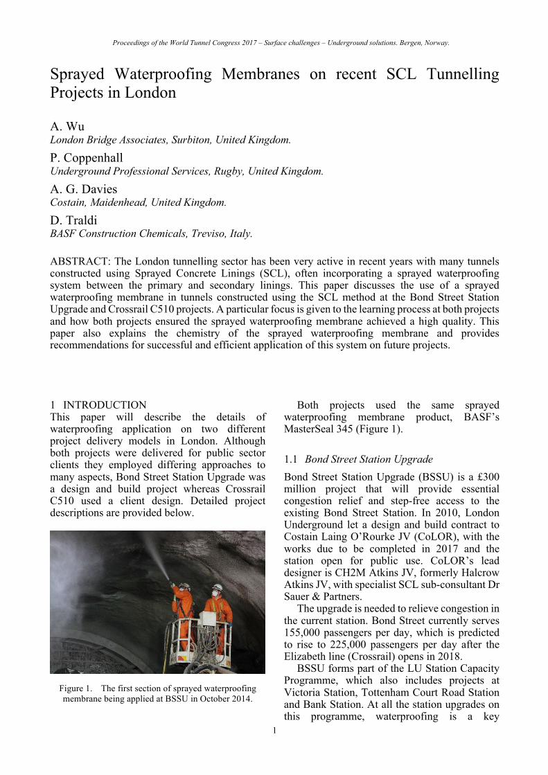
BSSU involves the construction of over 450m (Figure 2) of new passageways and shafts. SCL tunnelling is the primary methodology with a small section carried-out using traditional handworks. The upgrade also includes a connection to the new Crossrail Bond Street Station, constructed using SCL and traditional squareworks methods.
Figure 2. 3D model of Bond Street Station with new
tunnels shown in yellow and blue.
1.1.1 Geology The geology at Bond Street Station is typical of its Central London location and consists of made ground, overlying the River Terrace Gravels, London Clay, the Lambeth group and the Thanet sands. The properties of the London Basin geology are widely published, therefore only a brief description is provided in this paper.
Most of the tunnels at BSSU are located within the London Clay with the deepest parts at Jubilee line level in the Upper Mottled Beds of the Lambeth Group.
At Bond Street, the London Clay consists of the A2 and A3 formations. Both formations were recorded as stiff to very stiff clay of low permeability (5.7 x10⁻⁸ to 7 x10-11 m/s) with occasional very stiff sandy clay. The underlying Lambeth group is divided into the Upper Mottled Beds, Lower Mottled Beds and the Upnor formation. The Upper Mottled Beds were recorded as stiff to very stiff fissured mottled clay with frequent sand lenses, sometimes extensive and water-bearing. For example, groundwater was encountered in a sand channel within the Upper Mottled Beds during the construction of BSSU’s Lift 3 Shaft (Section 5).
However, experience of leaks during the construction process (particularly in squareworks sections where a membrane was not used) and the following investigations demonstrated that water paths formed by existing structures should
be a significant consideration for waterproofing design. Testing of water samples demonstrated that water was likely originating from leaking water mains in the overlying made ground or gravels.
1.1.2 Challenges A key challenge for the design and construction of the station upgrade has been the very limited space for construction due to the existing underground station layout, the small construction site at 354-358 Oxford Street and the extensive surrounding third party structures including several listed buildings, sensitive brick-lined sewers, embassies, shops and a 4-star hotel. The congested nature of the existing station necessitated a complex geometry for the new SCL tunnels (Figure 2).
1.2 Crossrail C510 The Crossrail C510 contract is a £260 million project currently being undertaken by BBMV, a joint venture between Balfour Beatty, BeMo, Morgan Sindall and Vinci Grand Projets construction.
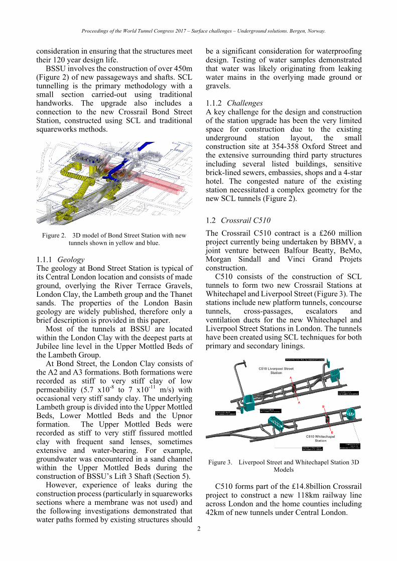
C510 consists of the construction of SCL tunnels to form two new Crossrail Stations at Whitechapel and Liverpool Street (Figure 3). The stations include new platform tunnels, concourse tunnels, cross-passages, escalators and ventilation ducts for the new Whitechapel and Liverpool Street Stations in London. The tunnels have been created using SCL techniques for both primary and secondary linings.
Figure 3. Liverpool Street and Whitechapel Station 3D
Models
C510 forms part of the £14.8billion Crossrail project to construct a new 118km railway line across London and the home counties including 42km of new tunnels under Central London.
Proceedings of the World Tunnel Congress 2017 – Surface challenges – Underground solutions. Bergen, Norway.
3
A detailed background of the Crossrail project has been provided in previously published papers, e.g. Tucker & Black (2016).
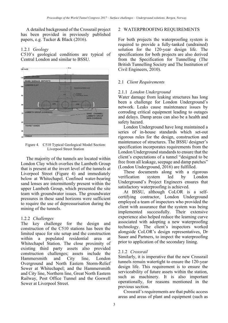
1.2.1 Geology C510’s geological conditions are typical of Central London and similar to BSSU.
Figure 4. C510 Typical Geological Model Section:
Liverpool Street Station
The majority of the tunnels are located within London Clay which overlies the Lambeth Group that is present at the invert level of the tunnels at Liverpool Street (Figure 4) and immediately below at Whitechapel. Confined water-bearing sand lenses are intermittently present within the upper Lambeth Group, which presented the site team with groundwater issues. The groundwater pressures in these sand horizons were sufficient to require the use of depressurisation during the mining of the tunnels.
1.2.2 Challenges The key challenge for the design and construction of the C510 stations has been the limited space for site setup and the construction within a populated residential area at Whitechapel Station. The close proximity of existing third party assets also provided construction challenges; assets include the Hammersmith and City line, London Overground and North Eastern Storm-Relief Sewer at Whitechapel; and the Hammersmith and City line, Northern line, Great North Eastern Railway, Post Office Tunnel and the Goswell Sewer at Liverpool Street.
2 WATERPROOFING REQUIREMENTS
For both projects the waterproofing system is required to provide a fully-tanked (undrained) solution for the 120-year design life. The specifications for both projects are also derived from the Specification for Tunnelling (The British Tunnelling Society and The Institution of Civil Engineers, 2010).
2.1 Client Requirements
2.1.1 London Underground Water damage from leaking structures has long been a challenge for London Underground’s network. Leaks cause maintenance issues by corroding critical equipment leading to outages and delays. Damp areas can also be a health and safety hazard.
London Underground have long maintained a series of in-house standards which set-out rigorous rules for the design, construction and maintenance of structures. The BSSU designer’s specification incorporates requirements from the London Underground standards to ensure that the client’s expectations of a tunnel “designed to be free from all leakage, seepage and damp patches” (London Underground, 2016) are fulfilled.
These documents along with a rigorous verification system led by London Underground’s Project Engineers ensures that satisfactory waterproofing is achieved.
At BSSU, although CoLOR is a self-certifying contractor, London Underground employed a team of inspectors who provided the client with assurance that the system was being implemented successfully. Their extensive experience also helped reduce the learning curve associated with adopting a new waterproofing technology. The client’s inspectors worked alongside CoLOR’s design representatives, Dr Sauer and Partners, to inspect the waterproofing prior to application of the secondary lining.
2.1.2 Crossrail Similarly, it is imperative that the new Crossrail tunnels remain watertight to ensure the 120-year design life. This requirement is to ensure the serviceability of future assets within the station, such as machinery. It is also important operationally, for reasons mentioned in the previous section.
Crossrail’s requirements are that public access areas and areas of plant and equipment (such as
Proceedings of the World Tunnel Congress 2017 – Surface challenges – Underground solutions. Bergen, Norway.
4
track) have no water ingress. However, other tunnels such as ventilation ducts have a limited allowance.
The Crossrail client representatives were meticulous in their inspection of the waterproofing, each part of the process was reviewed including the calculation of the required amount of material and post application quality checks detailed in Section 3.2.
2.2 Selection of methodologies There are different methods and products that can be used to waterproof tunnels, the selection of a product and method is usually governed by operational requirements of the tunnel, the tunnelling method and the design philosophy.
2.2.1 SCL Tunnels In SCL tunnels, waterproofing is a significant challenge due to the variability of the surface and the frequent joints through which water may pass with ease.
Pre-fabricated sheet membrane has traditionally been used to waterproof a conventionally excavated tunnel. Installed between the primary and secondary linings, the membrane acts as a separation between concrete linings. Sheet membranes are suited to situations of considerable water ingress but are typically complicated to install in underground sections with complex geometries.
To address the issues of physical and structural discontinuities created by a traditional sheet membrane, sprayed waterproofing membranes were developed. Sprayed membranes are particularly advantageous in geometrically complex areas, such as transitions, where traditional waterproofing can be difficult to apply.
2.2.2 Composite Linings Sprayed membrane systems can be used to create a composite action between the primary (outer) and secondary (inner) linings. This is a key differentiator as most sheet membranes do not provide a fully-bonded system. The fully-bonded characteristic of MasterSeal 345 is discussed in Section 3.1 of this paper.
Within London the current trend has been to create composite linings that use a sprayed waterproofing membrane, this design was applied to C510. The original design for C510 utilised a full sprayed waterproofing membrane to facilitate a partially-composite shell lining,
where the loads are shared between the primary and secondary linings.
2.2.3 Selected Methodologies At C510, BBMV trialled several products and systems to determine the appropriate waterproofing to be used. For the sprayed waterproofing membrane the MasterSeal 345, manufactured by BASF plc, was selected due to its flexibility and ease of application.
In contrast to C510, the design concept at BSSU considered the primary lining to deteriorate with time. The lining at BSSU typically consisted of a SCL primary lining, regulating layer, sprayed waterproofing membrane, SCL secondary lining and final regulating layer. The design philosophy relies upon producing a fully tanked solution where the SCL secondary lining is designed to carry full water pressure and ground loads. Further details of the BSSU SCL design have been previously published by Lyons et al. (2014).
At BSSU, independently of any other projects, CoLOR took the decision to proceed with BASF’s MasterSeal 345 system at the detailed design stage based upon technical information from the manufacturer and the LU Approved Products Register, which includes a technical evaluation report produced by Mott MacDonald. On-site trials were later carried out to verify the technical data and ensure the suitability of the selected regulating layer which is critical to the efficient application of a sprayed membrane.
2.2.4 Revised Methodology at C510 The C510 team encountered groundwater issues at the stations, which were predominantly within the invert of the tunnel. To overcome this, the sprayed membrane was replaced with a combination of sheet and sprayed membranes. In certain locations, where the tunnel has encountered difficult ground conditions and significant amounts of water, a full circumferential sheet lining has been used.
3 SPRAYED MEMBRANE
As both the projects discussed in this paper selected MasterSeal 345 to form their waterproofing membrane a detailed description of its properties is provided below. Application procedures and lessons learnt are also discussed which could be applicable to any similar sprayed waterproofing membrane product.
Proceedings of the World Tunnel Congress 2017 – Surface challenges – Underground solutions. Bergen, Norway.
5
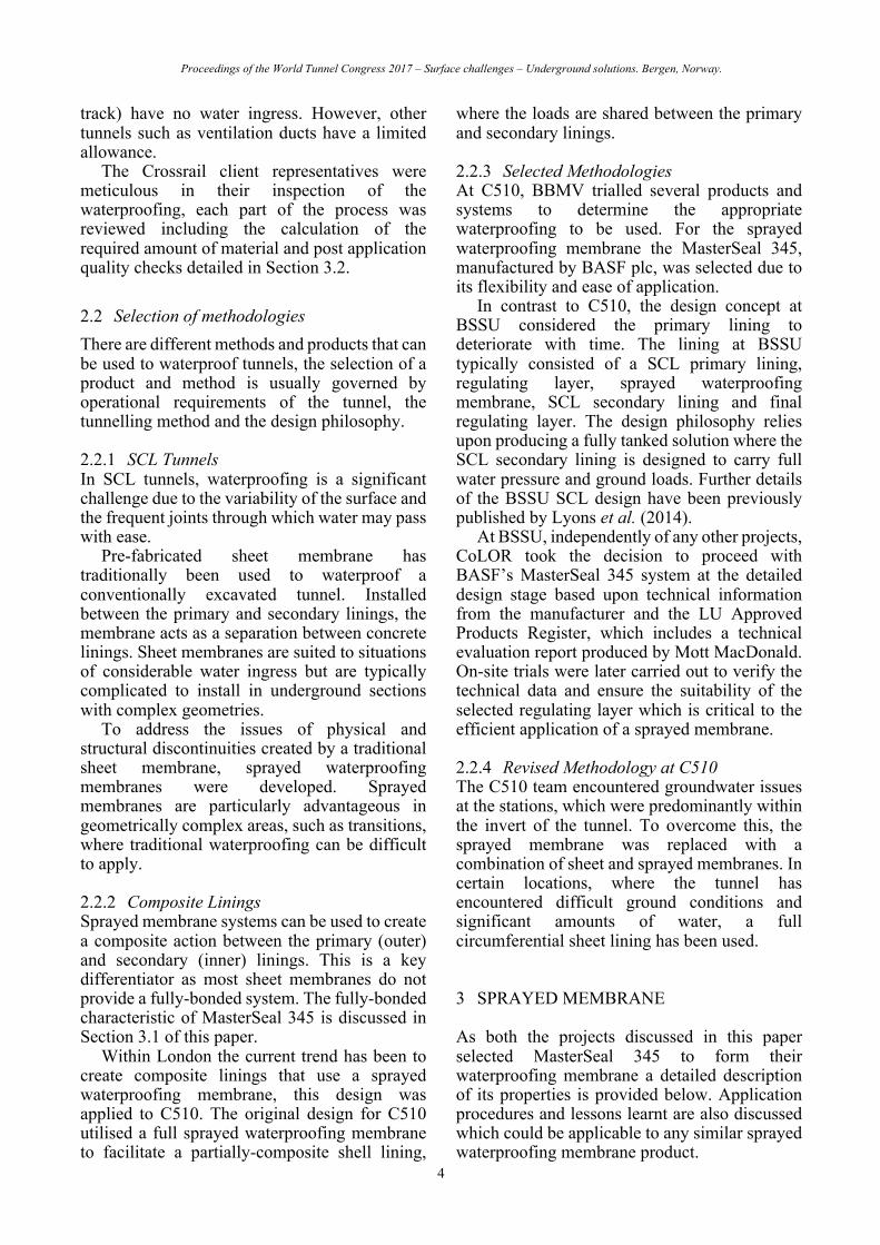
3.1 MasterSeal 345 Properties MasterSeal 345 is a specially formulated product, its basic raw material is a re-dispersible EVA (Ethylene Vinyl Acetate) polymer. The EVA polymer is key to the properties and behaviour of the membrane, providing the membrane with flexibility, chemical resistance and a high friction coefficient. Beside this polymer, the formulation also consists of fillers which contribute to the long-term behaviour and curing mechanism. EVA is an organic polymer and is formed by polymerization of monomers (Figure 5).
Figure 5. A typical monomer
MasterSeal 345 exhibits, after curing, long-term waterproofing properties. The extensive use of chemically similar materials in the construction industry, such as EVA-based sealants and resins, with comparable applications and lifetime exposure conditions has demonstrated long-term durability.
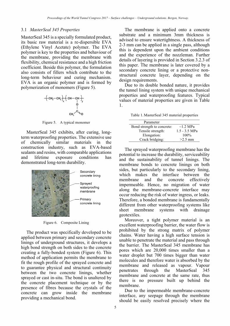
Figure 6. Composite Lining
The product was specifically developed to be applied between primary and secondary concrete linings of underground structures, it develops a high bond strength on both sides to the concrete creating a fully-bonded system (Figure 6). This method of application permits the membrane to fit the rough profile of the sprayed concrete and to guarantee physical and structural continuity between the two concrete linings, whether sprayed or cast in-situ. The bond is unaltered by the concrete placement technique or by the presence of fibres because the crystals of the concrete can grow inside the membrane providing a mechanical bond.
The membrane is applied onto a concrete substrate and a minimum 3mm thickness is advised to ensure watertightness. A thickness of 2-3 mm can be applied in a single pass, although this is dependent upon the ambient conditions and the experience of the nozzleman. Further details of layering is provided in Section 3.2.3 of this paper. The membrane is later covered by a secondary concrete lining or a protective non-structural concrete layer, depending on the design requirements.
Due to its double bonded nature, it provides the tunnel lining system with unique mechanical properties and waterproofing features. Typical values of material properties are given in Table 1.
Table 1. MasterSeal 345 material properties
Parameter Bond strength to concrete: ~1.2 MPa
Tensile strength: 1.5 - 3.5 MPa Elongation: 100%
Crack bridging: >2.5 mm The sprayed waterproofing membrane has the
potential to increase the durability, serviceability and the sustainability of tunnel linings. The membrane bonds to concrete linings on both sides, but particularly to the secondary lining, which makes the interface between the membrane and the concrete effectively impermeable. Hence, no migration of water along the membrane-concrete interface may occur reducing the risk of water ingress, or leaks. Therefore, a bonded membrane is fundamentally different from other waterproofing systems like sheet membrane systems with drainage geotextiles.
Moreover, a tight polymer material is an excellent waterproofing barrier, the water flow is prohibited by the strong matrix of polymer chains. Water having a high surface tension is unable to penetrate the material and pass through the barrier. The MasterSeal 345 membrane has pores which are 20,000 times smaller than a water droplet but 700 times bigger than water molecules and therefore water is absorbed by the membrane and released as vapour. Vapour penetrates through the MasterSeal 345 membrane and concrete at the same rate, thus there is no pressure built up behind the membrane.
Due to the impermeable membrane-concrete interface, any seepage through the membrane should be easily resolved precisely where the
Proceedings of the World Tunnel Congress 2017 – Surface challenges – Underground solutions. Bergen, Norway.
6
seepage occurs since this point corresponds to the seepage channel in the primary lining. For a leak to occur in a double bonded system, water must find a path through three failure zones. Firstly, a crack in the primary lining, then a tear in the membrane followed by a second crack in the secondary lining. These failure zones need to occur at the same point since water cannot migrate along the membrane-concrete interface (Figure 7).
Figure 7. Failure mechanism for fully-bonded
membrane
3.2 Application Procedures
3.2.1 Regulating layer On both BSSU and C510, a regulating layer was applied to the primary lining prior to the application of the sprayed waterproofing membrane.
A regulating layer provides a smoother surface which is advisable given the high value of membrane compared to the cost of regulating layer. To achieve this minimum thickness on an uneven surface by spray application, more material must be applied at a rate which is broadly proportional to the roughness of the surface.
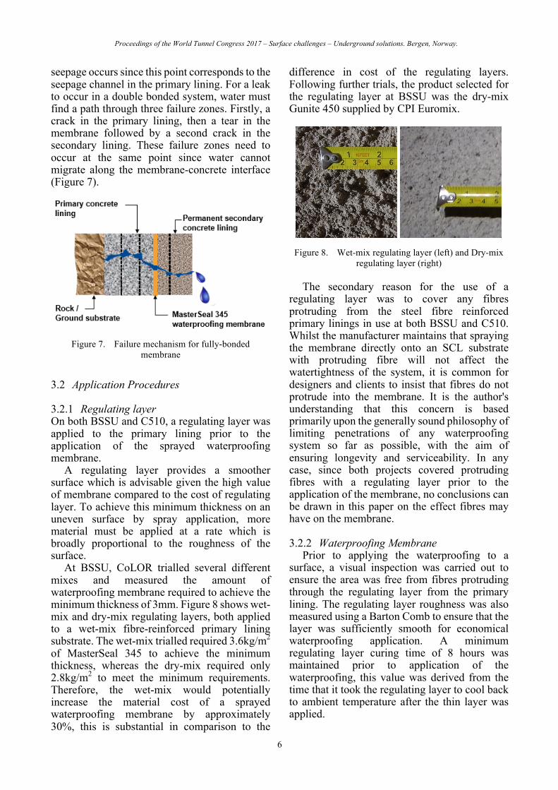
At BSSU, CoLOR trialled several different mixes and measured the amount of waterproofing membrane required to achieve the minimum thickness of 3mm. Figure 8 shows wet-mix and dry-mix regulating layers, both applied to a wet-mix fibre-reinforced primary lining substrate. The wet-mix trialled required 3.6kg/m2 of MasterSeal 345 to achieve the minimum thickness, whereas the dry-mix required only 2.8kg/m2 to meet the minimum requirements. Therefore, the wet-mix would potentially increase the material cost of a sprayed waterproofing membrane by approximately 30%, this is substantial in comparison to the
difference in cost of the regulating layers. Following further trials, the product selected for the regulating layer at BSSU was the dry-mix Gunite 450 supplied by CPI Euromix.
Figure 8. Wet-mix regulating layer (left) and Dry-mix
regulating layer (right)
The secondary reason for the use of a regulating layer was to cover any fibres protruding from the steel fibre reinforced primary linings in use at both BSSU and C510. Whilst the manufacturer maintains that spraying the membrane directly onto an SCL substrate with protruding fibre will not affect the watertightness of the system, it is common for designers and clients to insist that fibres do not protrude into the membrane. It is the author's understanding that this concern is based primarily upon the generally sound philosophy of limiting penetrations of any waterproofing system so far as possible, with the aim of ensuring longevity and serviceability. In any case, since both projects covered protruding fibres with a regulating layer prior to the application of the membrane, no conclusions can be drawn in this paper on the effect fibres may have on the membrane.
3.2.2 Waterproofing Membrane Prior to applying the waterproofing to a
surface, a visual inspection was carried out to ensure the area was free from fibres protruding through the regulating layer from the primary lining. The regulating layer roughness was also measured using a Barton Comb to ensure that the layer was sufficiently smooth for economical waterproofing application. A minimum regulating layer curing time of 8 hours was maintained prior to application of the waterproofing, this value was derived from the time that it took the regulating layer to cool back to ambient temperature after the thin layer was applied.
Proceedings of the World Tunnel Congress 2017 – Surface challenges – Underground solutions. Bergen, Norway.
7
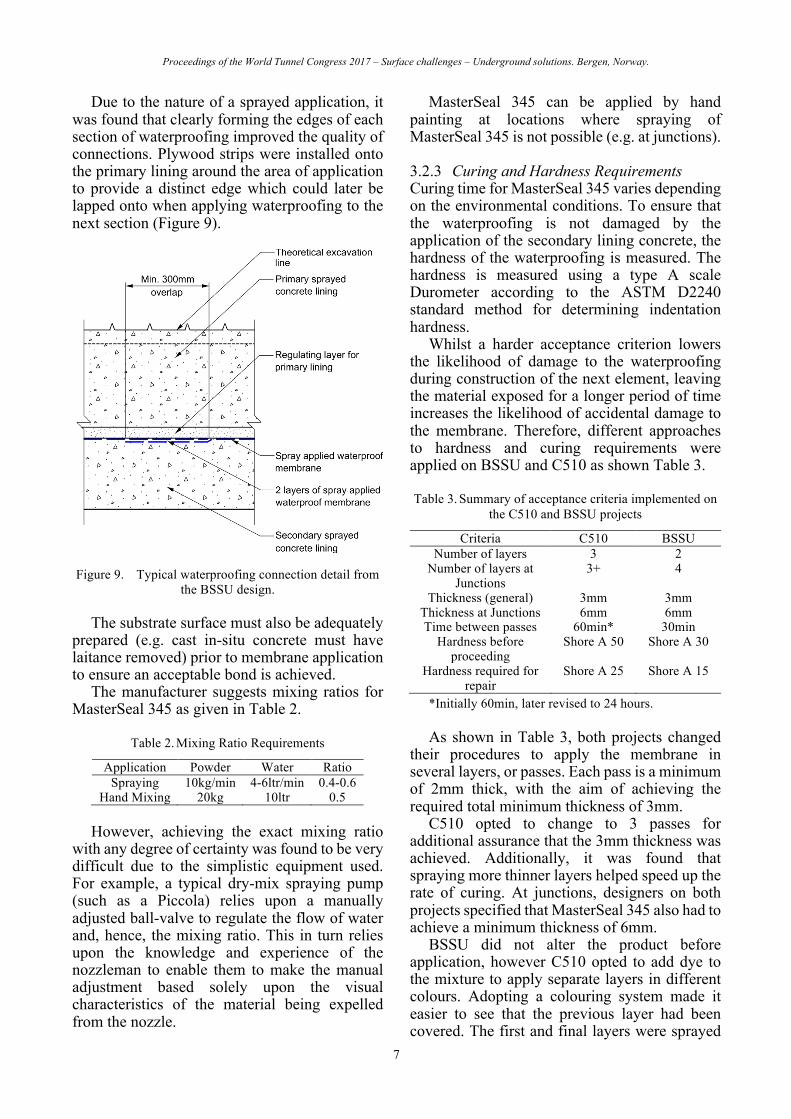
Due to the nature of a sprayed application, it was found that clearly forming the edges of each section of waterproofing improved the quality of connections. Plywood strips were installed onto the primary lining around the area of application to provide a distinct edge which could later be lapped onto when applying waterproofing to the next section (Figure 9).
Figure 9. Typical waterproofing connection detail from
the BSSU design.
The substrate surface must also be adequately prepared (e.g. cast in-situ concrete must have laitance removed) prior to membrane application to ensure an acceptable bond is achieved.
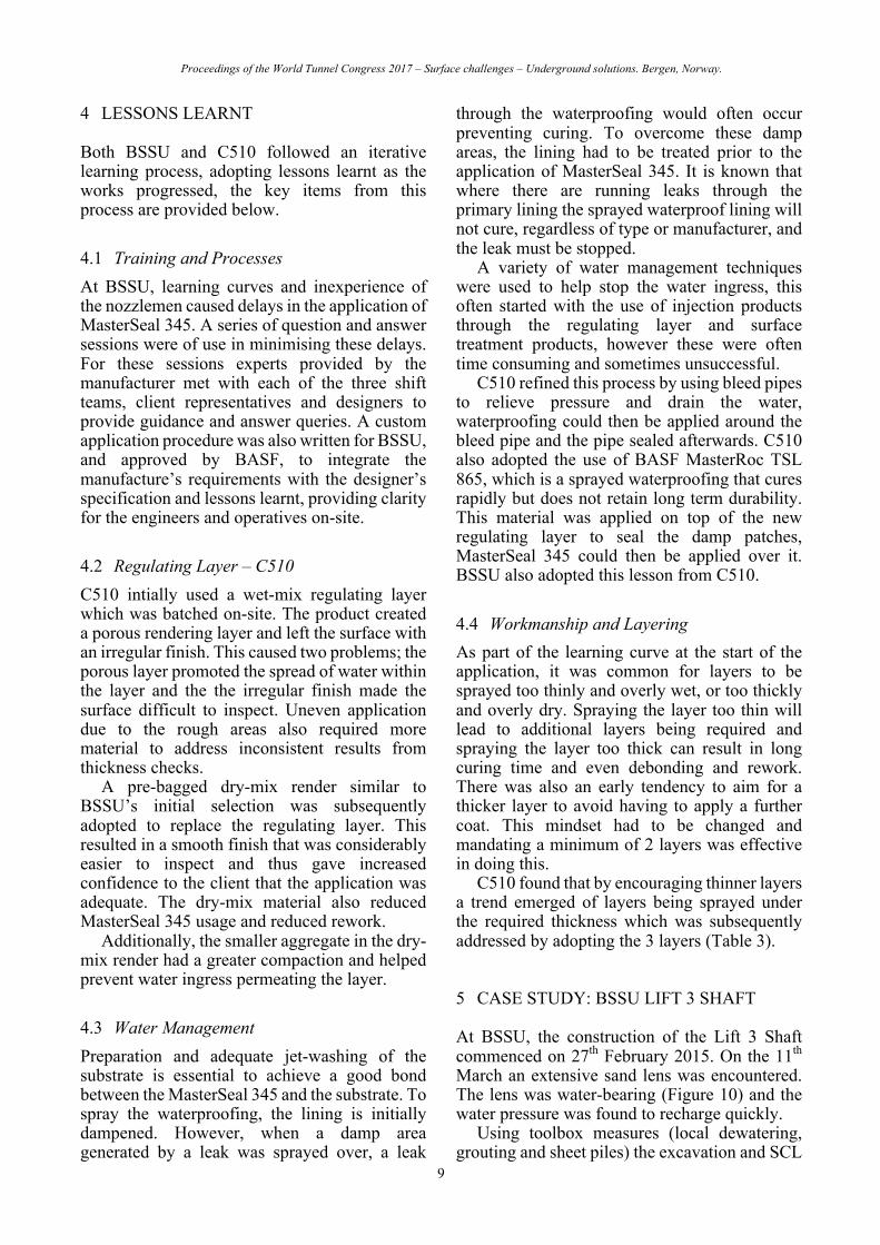
The manufacturer suggests mixing ratios for MasterSeal 345 as given in Table 2.
Table 2. Mixing Ratio Requirements
Application Powder Water Ratio Spraying 10kg/min 4-6ltr/min 0.4-0.6
Hand Mixing 20kg 10ltr 0.5 However, achieving the exact mixing ratio
with any degree of certainty was found to be very difficult due to the simplistic equipment used. For example, a typical dry-mix spraying pump (such as a Piccola) relies upon a manually adjusted ball-valve to regulate the flow of water and, hence, the mixing ratio. This in turn relies upon the knowledge and experience of the nozzleman to enable them to make the manual adjustment based solely upon the visual characteristics of the material being expelled from the nozzle.
MasterSeal 345 can be applied by hand painting at locations where spraying of MasterSeal 345 is not possible (e.g. at junctions).
3.2.3 Curing and Hardness Requirements Curing time for MasterSeal 345 varies depending on the environmental conditions. To ensure that the waterproofing is not damaged by the application of the secondary lining concrete, the hardness of the waterproofing is measured. The hardness is measured using a type A scale Durometer according to the ASTM D2240 standard method for determining indentation hardness.
Whilst a harder acceptance criterion lowers the likelihood of damage to the waterproofing during construction of the next element, leaving the material exposed for a longer period of time increases the likelihood of accidental damage to the membrane. Therefore, different approaches to hardness and curing requirements were applied on BSSU and C510 as shown Table 3.
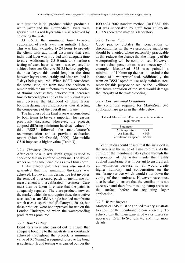
Table 3. Summary of acceptance criteria implemented on the C510 and BSSU projects
Criteria C510 BSSU Number of layers 3 2
Number of layers at Junctions
3+ 4
Thickness (general) 3mm 3mm Thickness at Junctions 6mm 6mm Time between passes 60min* 30min
Hardness before proceeding
Shore A 50 Shore A 30
Hardness required for repair
Shore A 25 Shore A 15
*Initially 60min, later revised to 24 hours. As shown in Table 3, both projects changed
their procedures to apply the membrane in several layers, or passes. Each pass is a minimum of 2mm thick, with the aim of achieving the required total minimum thickness of 3mm.
C510 opted to change to 3 passes for additional assurance that the 3mm thickness was achieved. Additionally, it was found that spraying more thinner layers helped speed up the rate of curing. At junctions, designers on both projects specified that MasterSeal 345 also had to achieve a minimum thickness of 6mm.
BSSU did not alter the product before application, however C510 opted to add dye to the mixture to apply separate layers in different colours. Adopting a colouring system made it easier to see that the previous layer had been covered. The first and final layers were sprayed
Proceedings of the World Tunnel Congress 2017 – Surface challenges – Underground solutions. Bergen, Norway.
8
with just the initial product, which produce a white layer and the intermediate layers were sprayed with a red layer which was achieved by colouring the water.
At C510, the minimum time between application of each layer was initially 1 hour. This was later extended to 24 hours to provide the client with additional assurance that each individual layer was provided with adequate time to cure. Additionally, C510 undertook hardness testing of each layer, where it was expected to achieve between Shore A 20-25 before applying the next layer, this could lengthen the time between layers considerably and often resulted in 7 days being required. When BSSU considered the same issue, the team took the decision to remain with the manufacturer’s recommendation of 30mins because they believed that increased time between application of the individual layers may decrease the likelihood of these layers bonding during the curing process, thus affecting the competence of the overall membrane.
The hardness of the final layer was considered by both teams to be very important for reasons previously discussed. However, the projects adopted differing minimum hardness values for this. BSSU followed the manufacturer’s recommendation and a previous evaluation report (Mott MacDonald, 2009). Meanwhile C510 imposed a higher value (Table 3).
3.2.4 Thickness Checks After each pass, a wet depth gauge is used to check the thickness of the membrane. The device works on the same principle as a wet film comb.
A dry cut-out patch test was also used to guarantee that the minimum thickness was achieved. However, this destructive test involves the removal of a cured patch of membrane for measurement with a calibrated micrometer. Care must then be taken to ensure that the patch is adequately repaired. There are products now on the market which do not require these destructive tests, such as an MMA single bonded membrane which uses a ‘spark test’ (Ballantyne, 2016), but these products were not approved for use on the London Underground when the waterproofing product was procured.
3.2.5 Bond Testing Bond tests were also carried out to ensure that adequate bonding to the substrate was constantly achieved throughout the project, a minimum value of 0.5N/mm2 is required to prove the bond is sufficient. Bond testing was carried out per the
ISO 4624:2002 standard method. On BSSU, this test was undertaken by staff from an on-site UKAS accredited materials laboratory.
3.2.6 Penetrations Good practice dictates that penetrations or discontinuities in the waterproofing membrane should be avoided where reasonably practicable as this reduces the chance that the integrity of the waterproofing will be compromised. However, where rebar penetrations were necessary for example, MasterSeal 345 was painted a minimum of 100mm up the bar to maximise the chance of a waterproof seal. Additionally, the team on BSSU opted to use only stainless steel rebar for this purpose to reduce the likelihood that future corrosion of the steel would damage the integrity of the waterproofing.
3.2.7 Environmental Conditions The conditions required for MasterSeal 345 application are given in the table below.
Table 4. MasterSeal 345 environmental condition requirements
Parameter Air temperature >5°C
Air humidity <90% Ventilation air speed 1-5m/s
Ventilation should ensure that the air speed in
the area is in the range of 1 m/s to 5 m/s. As the curing of the membrane takes place through the evaporation of the water inside the freshly applied membrane, it is important to ensure fresh air ventilation because hot air would create higher humidity and condensation on the membrane surface which would slow down the curing of the membrane. However, care must also be taken to ensure that the ventilation is not excessive and therefore masking damp areas on the surface before the regulating layer application.
3.2.8 Water Ingress MasterSeal 345 must be applied to a dry substrate to allow for the membrane to cure correctly. To achieve this the management of water ingress is necessary. Refer to Sections 4.3 and 5 for more details.
Proceedings of the World Tunnel Congress 2017 – Surface challenges – Underground solutions. Bergen, Norway.
9
4 LESSONS LEARNT
Both BSSU and C510 followed an iterative learning process, adopting lessons learnt as the works progressed, the key items from this process are provided below.
4.1 Training and Processes At BSSU, learning curves and inexperience of the nozzlemen caused delays in the application of MasterSeal 345. A series of question and answer sessions were of use in minimising these delays. For these sessions experts provided by the manufacturer met with each of the three shift teams, client representatives and designers to provide guidance and answer queries. A custom application procedure was also written for BSSU, and approved by BASF, to integrate the manufacture’s requirements with the designer’s specification and lessons learnt, providing clarity for the engineers and operatives on-site.
4.2 Regulating Layer – C510 C510 intially used a wet-mix regulating layer which was batched on-site. The product created a porous rendering layer and left the surface with an irregular finish. This caused two problems; the porous layer promoted the spread of water within the layer and the the irregular finish made the surface difficult to inspect. Uneven application due to the rough areas also required more material to address inconsistent results from thickness checks.
A pre-bagged dry-mix render similar to BSSU’s initial selection was subsequently adopted to replace the regulating layer. This resulted in a smooth finish that was considerably easier to inspect and thus gave increased confidence to the client that the application was adequate. The dry-mix material also reduced MasterSeal 345 usage and reduced rework.
Additionally, the smaller aggregate in the dry-mix render had a greater compaction and helped prevent water ingress permeating the layer.
4.3 Water Management Preparation and adequate jet-washing of the substrate is essential to achieve a good bond between the MasterSeal 345 and the substrate. To spray the waterproofing, the lining is initially dampened. However, when a damp area generated by a leak was sprayed over, a leak
through the waterproofing would often occur preventing curing. To overcome these damp areas, the lining had to be treated prior to the application of MasterSeal 345. It is known that where there are running leaks through the primary lining the sprayed waterproof lining will not cure, regardless of type or manufacturer, and the leak must be stopped.
A variety of water management techniques were used to help stop the water ingress, this often started with the use of injection products through the regulating layer and surface treatment products, however these were often time consuming and sometimes unsuccessful.
C510 refined this process by using bleed pipes to relieve pressure and drain the water, waterproofing could then be applied around the bleed pipe and the pipe sealed afterwards. C510 also adopted the use of BASF MasterRoc TSL 865, which is a sprayed waterproofing that cures rapidly but does not retain long term durability. This material was applied on top of the new regulating layer to seal the damp patches, MasterSeal 345 could then be applied over it. BSSU also adopted this lesson from C510.
4.4 Workmanship and Layering As part of the learning curve at the start of the application, it was common for layers to be sprayed too thinly and overly wet, or too thickly and overly dry. Spraying the layer too thin will lead to additional layers being required and spraying the layer too thick can result in long curing time and even debonding and rework. There was also an early tendency to aim for a thicker layer to avoid having to apply a further coat. This mindset had to be changed and mandating a minimum of 2 layers was effective in doing this.
C510 found that by encouraging thinner layers a trend emerged of layers being sprayed under the required thickness which was subsequently addressed by adopting the 3 layers (Table 3).
5 CASE STUDY: BSSU LIFT 3 SHAFT
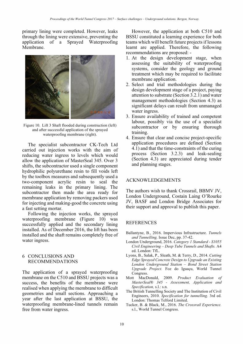
At BSSU, the construction of the Lift 3 Shaft commenced on 27th February 2015. On the 11th March an extensive sand lens was encountered. The lens was water-bearing (Figure 10) and the water pressure was found to recharge quickly.
Using toolbox measures (local dewatering, grouting and sheet piles) the excavation and SCL
Proceedings of the World Tunnel Congress 2017 – Surface challenges – Underground solutions. Bergen, Norway.
10
primary lining were completed. However, leaks through the lining were extensive, preventing the application of a Sprayed Waterproofing Membrane.
Figure 10. Lift 3 Shaft flooded during construction (left)
and after successful application of the sprayed waterproofing membrane (right).
The specialist subcontractor CK-Tech Ltd carried out injection works with the aim of reducing water ingress to levels which would allow the application of MasterSeal 345. Over 3 shifts, the subcontractor used a single component hydrophilic polyurethane resin to fill voids left by the toolbox measures and subsequently used a two-component acrylic resin to seal the remaining leaks in the primary lining. The subcontractor then made the area ready for membrane application by removing packers used for injecting and making-good the concrete using a fast setting mortar.
Following the injection works, the sprayed waterproofing membrane (Figure 10) was successfully applied and the secondary lining installed. As of December 2016, the lift has been installed and the shaft remains completely free of water ingress.
6 CONCLUSIONS AND RECOMMENDATIONS
The application of a sprayed waterproofing membrane on the C510 and BSSU projects was a success, the benefits of the membrane were realised when applying the membrane to difficult geometries and small sections. Approaching a year after the last application at BSSU, the waterproofing membrane-lined tunnels remain free from water ingress.
However, the application at both C510 and BSSU constituted a learning experience for both teams which will benefit future projects if lessons learnt are applied. Therefore, the following recommendations are proposed: - 1. At the design development stage, when
assessing the suitability of waterproofing systems, consider the geology and ground treatment which may be required to facilitate membrane application.
2. Select and trial methodologies during the design development stage of a project, paying attention to substrate (Section 3.2.1) and water management methodologies (Section 4.3) as significant delays can result from unmanaged water ingress.
3. Ensure availability of trained and competent labour, possibly via the use of a specialist subcontractor or by ensuring thorough training.
4. Ensure that clear and concise project-specific application procedures are defined (Section 4.1) and that the time-constraints of the curing process (Section 3.2.3) and leak-sealing (Section 4.3) are appreciated during tender and planning stages.
ACKNOWLEDGEMENTS
The authors wish to thank Crossrail, BBMV JV, London Underground, Costain Laing O’Rourke JV, BASF and London Bridge Associates for their support and approval to publish this paper.
REFERENCES
Ballantyne, B., 2016. Impervious Infrastructure. Tunnels and Tunnelling, Issue Dec, pp. 37-42.
London Underground, 2016. Category 1 Standard - S1055 Civil Engineering – Deep Tube Tunnels and Shafts. A4 ed. London: TfL.
Lyons, B., Salak, P., Sleath, M. & Terry, D., 2014. Cutting Edge Sprayed Concrete Design to Upgrade an Existing London Underground Station – Bond Street Station Upgrade Project. Foz do Iguaçu, World Tunnel Congress.
Mott MacDonald, 2009. Product Evaluation of MasterSeal® 345 - Assessment, Application and Specification, s.l.: s.n.
The British Tunnelling Society and The Institution of Civil Engineers, 2010. Specification for tunnelling. 3rd ed. London: Thomas Telford Limited.
Tucker, B. & Black, M., 2016. The Crossrail Experience. s.l., World Tunnel Congress.