Embed Size (px)
Citation preview

CAT.NO.286E
For Automobiles
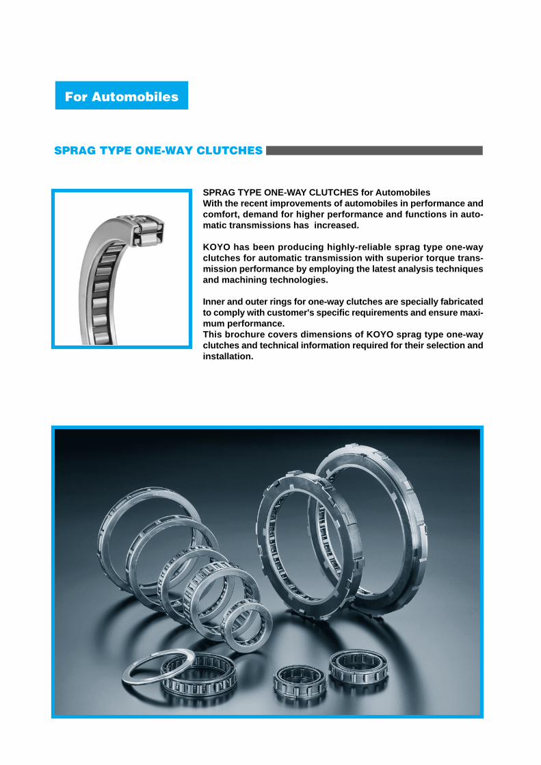
SPRAG TYPE ONE-WAY CLUTCHES for AutomobilesWith the recent improvements of automobiles in performance andcomfort, demand for higher performance and functions in auto-matic transmissions has increased.
KOYO has been producing highly-reliable sprag type one-wayclutches for automatic transmission with superior torque trans-mission performance by employing the latest analysis techniquesand machining technologies.
Inner and outer rings for one-way clutches are specially fabricatedto comply with customer's specific requirements and ensure maxi-mum performance.This brochure covers dimensions of KOYO sprag type one-wayclutches and technical information required for their selection andinstallation.
SPRAG TYPE ONE-WAY CLUTCHES
For Automobiles

SPRAG TYPE ONE-WAY CLUTCHES
Page
2223344
5
55666
7
777888
9
99
10
101010
10
1011
12
14
16
1. Functions and Structure of One-way Clutches
1.1 Functions1.2 Structure1.3 Nomenclature1.4 Designation1.5 Principle of Torque Transmission1.6 Strut Angle
2. Rated Torque and Drag Torque
2.1 Rated Torque2.2 Required Rated Torque2.3 Drag Torque2.4 Types of Sprags2.5 Sprag Selection
3. Mounting and Design of Inner and Outer Rings
3.1 Support of Radial Load3.2 Axial Mounting3.3 Materials and Hardness of Inner and Outer Rings3.4 Sectional Height of Inner and Outer Rings3.5 Chamfering of Inner and Outer Rings3.6 Precision of Inner and Outer Rings
4. Lubrication
4.1 Lubricant4.2 Lubrication Method
5. Mounting
5.1 Mounting to Outer Ring5.2 Mounting to Inner Ring5.3 Simultaneous Mounting to Outer and Inner Rings
6. Troubleshooting
6.1 Popping and Pop-out6.2 Roll-over
7. Performance Evaluation Test
8. Dimension Table
9. Application Example
CONTENTS

●KW Series The KW Series controls sprag position with the inner andouter cages. The two cages enhance engagement between the spragsand ensure stable torque transmission.
●KX Series KX Series controls sprag position with a uniquely shapedspring. A single cage contributes to reduction in weight andinertia torque.
1.1 Functions
The one-way clutch is a functional component locatedbetween cylindrical inner and outer rings for transmitting orsuspending torque, which transmits torque in one rotationaldirection while stopping torque transmission in the oppositedirection.
1.2 Structure
In the KOYO sprag type one-way clutches, KW and KXSeries are selected according to desired application.The respective features are detailed below.
1. Functions and Structure of One-way Clutches
Fig. 1.2 Structure of KW Series One-way Clutch
Fig. 1.3 Structure of KX Series One-way Clutch
2
End bearing
Cage
Spring
Overrunning
Input
Input
Fig. 1.1 Typical Applications of One-way Clutches
The inner ring easily overruns in the torque suspension
direction.
Rotational direction of the outer ring determines
transmission and non-transmission of torque.
No torque transmission
Torque transmission
Input
End bearing
Inner cage
Outer cage
Spring
Sprag Drag clip
Sprag
Torque transmission
●
●

SPRAG TYPE ONE-WAY CLUTCHES
3
1.3 Nomenclature
●Sprag Mates between inner and outer rings to transmit torque. High-carbon chromium steel is drawn and heat-treated toobtain 60 HRC or more hardness.
●Cage Arranges sprags equally on the circumference for uniformtorque transmission. The cage is made of heat-treated carbon steel plate.
●Spring Maintaines constant sprag with the inner and outer ringsto ensure engagement of sprangs. The spring is made of stainless steel sheet or special alloysteel plate and is precision-stamped.
●End bearing Keeps the inner and outer rings on centered to maintain aconstant spase, if the radial load on the one-way clutch isonly small when overrunning. The end bearing is generally made of bronze or similarmaterials, although other materials are available in accor-dance with the load, rotational speed, and lubricationrequirements.
●Drag clip Several pieces are provided on the outer diameter surfaceof the cage. The drag clip secures the cage against the outer ring by aspring action in order to synchronize movement of the cagewith the outer ring for positive and prompt engagement of thesprags. The clip is made of stainless steel plate.
● T bar In the one-way clutch without end bearings, T bars stampedon the cage provide the same spring action and function asthat of the drag clips.
T bar
Fig. 1.4 Cage with T Bar
KW0571300
Serial number
Width number
Bore diameternumber
Series code
For details of inner ring raceway diameter dimensions and mounting width, refer to thedimension table.
13
057
KWKX
00,01,02, ・ ・ ・
1.4 Designation
(Example)
:
:
:
::
Distinguishes the same bore diameternumbers and width numbers
Width 13 to 13.999 mm
Bore diameter 57 to 57.999 mm
KW SeriesKX Series

1.6 Strut Angle
The positional relationship of the sprag engaging with theinner and outer rings is shown in Fig. 1.8. The angles α and β are called the strut angles on theinner and outer ring respectively.
1.5 Principle of Torque Transmission
The sprags are arranged equally on the circumferencebetween the inner and outer rings by the cage and areconstantly in contact with the inner and outer rings by springforce. Since the sprags are larger than the space between theinner and outer rings, they are arranged at an angle to theraceway surfaces of the inner and outer rings. The sprag surfaces in contact with the inner and outersurfaces are shaped such that the sprag height appears toincrease when the sprags rotate around their centers (Fig.1.5).
Fig. 1.5 Sprag Shape and Arrangement
When the outer ring rotates clockwise as shown in Fig. 1.6,friction between the outer ring and the sprag contact surfacecauses the sprags to incline clockwise and engage with theinner and outer rings to transmit torque.
Fig. 1.8 Strut Angle
Fig. 1.6 Sprag Position in Torque Transmission
4
Fig. 1.7 Sprag Position in Freewheeling
When the outer ring rotates counterclockwise as shown inFig. 1.7, the sprags incline counterclockwise to disengagewith the inner and outer rings, thus freewheeling the outerring.
Sprag
Cage
Spring force
SpringOuter ring
Inner ring
Outer ring
Inner ring
Outer ring
Inner ring
Outer ring
Inner ring
α�
β�

SPRAG TYPE ONE-WAY CLUTCHES
5
The sprag type one-way clutch is designed to transmittorque by friction between the contacting surfaces of thesprag with the inner ring and the outer ring. If tanα with tanβ exceed the friction coefficient μ of therespective contacting surfaces, the sprags slip and fail toengage hence transmitting no torque. When tanα and tanβ are excessively small, the load on thecontacting surfaces becomes large, thus decreasing torquetransmission capability. Since α is always greater than β , tanα is smaller than μfor torque transmission. KOYO sets optimum strut angles for maximum torquetransmission without slip on the contacting surfaces.
Fig. 2.1 Correction Coefficient of Rated Torque
Under operation with torsional vibration, the rated torquemust be set sufficiently large to cover the actual maximumtorque. Temporary excessive torque 1.5 to 2 times the rated torquecan be loaded. If excessive torque is anticipated frequently,however, the excessive torque shall be regarded as the actualmaximum torque. For detailed discussion about rated torque, consult with theKOYO representatives.
The rated torque is calculated based on the fact that theinner and outer rings employed for the one-way clutch havesufficient rigidity and that the raceway surfaces are machinedto the specified dimensional precision. Therefore, the material,hardness, dimensional precision, sectional thickness, andlubrication of the raceway surfaces shall be properly selected;otherwise, the endurance performance of the one-way clutchmay deteriorate.
2.2 Required Rated Torque
The required rated torque of the sprag type one-way clutchto satisfy the required endurance performance is calculatedas follows.
Tc T ≧ ─── ・・・・・・・(2.1)
fc
where
2. Rated Torque and Drag Torque
2.1 Rated Torque
The rated torque of the sprag type one-way clutch is afunction of the fatigue strength of the contacting surfaces onthe sprag. The rated torque is the limit in which the clutch functionswithout slip or harmful plastic deformation after repeatedapplication of torque on the one-way clutch, and withoutflaking on the sprag or raceway surfaces due to fatigue after10 6 repetitions of torque application. Since the stress generated on the contacting surfaces islarger on the inner ring side than the outer ring side, the ratedtorque is calculated based on the stress on the inner ringside. The values are shown in the dimension table.
1050
1
2
107106
f cC
orre
ctio
n co
effic
ient
Repetition of torque
T
T c
f c
:
:
:
Required rated torque, N ・ m
Actual maximum torque, N ・ m
Correction coefficient, N ・ m
When the required endurance performance of the clutch is106, set fc to 1. For endurance performance other than 106, obtain thecorrection coefficient from Fig. 2.1 and calculate the requiredrated torque from expression 2.1.

2.3 Drag Torque
The sprag type one-way clutch slips between the sprag andthe inner ring in freewheeling, generating frictional torque,known as drag torque. Since the sprag comes into contact with the inner ring due tospring, the drag torque is determined by spring force. Spring force is relatively small, and the sprag rotates at thesame speed as the outer ring. When the outer ring rotates,centrifugal force acts on the sprag, and so the drag torquethus varies according to the rotational speed of the outer ring.
2.4 Types of Sprags
According to the sprag gravitational center location, thecontacting force between the sprag and the inner ringchanges under the influence of the centrifugal force causedby rotation on the sprag. (Fig. 2.2) The respective sprags are engage and disengage types.
The relationship between the rotational speed of the outerring and the drag torque is shown in Fig. 2.3. The rotational speed at which the drag torque becomes zeroin the disengage type is called the disengage speed, abovewhich the sprag does not come in contact with the inner ring.
2.5 Sprag Selection
It is important to select appropriate sprags for specificoperating conditions in order to operate the for an extendedperiod of time. The sprag types are selected according to the static androtational conditions of the inner and outer rings (Table 2.1).
Fig. 2.3 Relationship between Outer-ring Rotation
Speed and Drag Torque
Fig. 2.2 Types of Sprag and the Effect of Centrifugal Force
6
Since the engage type increases drag torque with theincrease in rotational speed of the outer ring, the spragpositively engages with the inner and outer rings when itchanges to the engagement condition during the outer ringrotation. Since the disengage type decreases drag torque with theincrease in rotational speed of the outer ring, wear on thesprag and inner ring raceway surface is reduced.However the disengage type is not suitable for engagementin high-speed rotation. When the static and rotational conditions are not coveredby Table 2.1, consult KOYO representatives.
Engage Type
Usable
Suitable
Suitable
OuterRing
InnerRing
RotationalConditions
Table 2.1 Selection of Sprag Type According to Static and Rotational Conditions
Sprag Type
Disengage Type
Suitable
Unusable
Suitable
Engage type sprag
Disengage type sprag
Outer ring
Outer ring
Inner ring
Inner ring
Gravitational center of sprag
Centrifugal force
Gravitational center of sprag
Centrifugal force
The contacting force between the sprag and the inner ring reduces according to the centrifugal force
The contacting force between the sprag and the inner ring enlarges according to the centrifugal force
Engage type
Disengage type
Disengage speedRotational speed
Dra
g to
rque
Static
Rotation
Rotation
Rotation
Rotation
Static

SPRAG TYPE ONE-WAY CLUTCHES
3.2 Axial Mounting
Mounting width of the sprag type one-way clutch shall beset to W f dimension or more as shown in the dimensionaltable. Use the retaining plates similar to that shown in Fig. 3.3 toretain the one-way clutch in the axial direction and to hold thelubricant. Ensure a clearance between retaining plate andinner ring of 0.5 to 2mm.
3. Mounting and Design of Inner and Outer Rings
3.1 Support of Radial Load
Since the sprag type one-way clutch cannot radial load,required the rolling bearing or plane bearing to support theradial load (Fig. 3.1).
Fig. 3.2 One-way Clutch with End Bearings
Relatively small radial loads such as dead load of the inneror outer ring alone can be supported by the sprag type one-way clutch with end bearing. The radial load supported by the one-way clutch with endbearings varies according to the lubricant, rotational speed,and other conditions. Consult KOYO representatives.
Fig. 3.1 Example of Radial Load Support Using Rolling
Bearing
3.3 Materials and Hardness of Inner and Outer Rings
The materials of the inner and outer rings shall havesufficient endurance against load by sprag engagement andwear due to sliding during freewheel. The materials shall also have impact strength and fatiguestrength when the repetition frequency of the load torque ishigh. According to these requirements, carburized and hardenedor induction hardened alloy steel is suitable for the inner andouter rings of the sprag type one-way clutch.Typical materials and heat treatment are shown in Table 3.1.
Fig. 3.3 Example of Axial Mounting
Table 3.1 Materials and Heat Treatment Example of Rings
For materials or if employing heat treatment other than theabove, consult KOYO representatives.
7
Induction hardened
25 to 30 HRC
1.5 mm or more
JIS S45C, S55C or similar
Surface hardness
Core hardness
Hardening depth(500HV)
Materials
Outer ring
Sprag
Inner ring
Rolling bearing
Outer ring
Sprag
Inner ring
End bearings
Outer ring
Mounting width ( f )Retainingplate
Retainingplate0.5 to2mm
Snap ring
Inner ring
Clearance (diametrically)
W
60 HRC or more
Carburized and hardened
35 to 45 HRC
1.3 mm or more
JIS SCr420, SCM415, or similar

3.4 Sectional Height of Inner and Outer Rings
Radial load is applied to the inner and outer rings of thesprag type one-way clutch by sprag engagement. Since tensile stress occurs on the external diametersurface of the outer ring in the circumferential direction, theouter ring must have sufficient tensile strength. Set the sectional height of the inner and outer rings asshown in Fig. 3.4.
3.5 Chamfering of Inner and Outer Rings
Chamfer of approx. 1 to 2 mm in length and 30°in anglemust be made at the ends of the raceway of the inner andouter rings to facilitate assembly of the one-way clutch (Fig.3.6).
Roundness
Cylindricity
Raceway surface roughness
0.013
0.003 /10
3 .0μm RZ
Concentricity φ 0.075
Table 3.3 Concentricity of Inner and Outer Ring Raceway Surface
Any notches or oil holes in the rings may cause deformityunder local stress, or excessive wear of the raceway surface,or cracking of the rings. For the strength of inner and outerrings with complicated contours, consult KOYO representatives.
Fig. 3.5 FEM Analysis Sample of Outer Ring
t o/d o = 1/8 or more
t i /D i = 1/10 or more
Fig. 3.4 Sectional Height of Rings3.6 Precision of Inner and Outer Rings
The inner and outer rings of the one-way clutch must bemade to the precision as shown below to ensure the ratedtorque of the sprag type one-way clutch and to obtain re-quired endurance performance.
Fig. 3.6 Chamfering Dimensions for Inner and Outer Rings
8
Use the minimum sectional height for t o and t i.
Table 3.2 Precision of Inner and Outer Ring Raceway Surface
t o
t iφd o
φDi
30°�
30°�
1 to 2mm
1 to 2mm
Inner ring
Outer ring
(Max. Unit: mm)
(Max. Unit: mm)
● The nominal dimensions and tolerances of the inner andouter ring raceway diameters must be as shown on thedimension table.
The precision of raceway surfaces other than the racewaydiameter must be as shown on Tables 3.2 and 3.3.
●

SPRAG TYPE ONE-WAY CLUTCHES
4. Lubrication
If a continuous oil groove as shown in Fig. 4.1 cannot beprovided due to the mechanical structure of the inner-ring-rotating clutch, an oil sump must be provided on the internaldiameter surface of the inner ring as shown in Fig. 4.2 toensure sufficient oil quantity.
Fig. 4.2 Oil Sump Example in the Case of Inner Ring Rotation
Fig. 4.1 Example of Oil Intake Hole for Forced Lubrication
9
Appropriate lubricant and adequate supply are vital toensure maximum performance of the sprag type one-wayclutch.
4.1 Lubricant
Lubricant must be carefully selected since it determinesfriction coefficient of the sprag with the inner or outer ring andinfluences torque transmission performance. In general, automatic transmission fluid is most suitable. Do not use lubricants containing extreme-pressure addi-tives, since they degrade the friction coefficient and affect theengagement performance of the sprag. The sprag type one-way clutch is operable at 160℃ ofinstantaneous temperature and 120℃ of continuous tempera-ture at the highest. If temperatures are anticipated to exceedthese limits, the lubricant shall be cooled to maintain the one-way clutch temperature below the above. Remove contaminants to keep the lubricant clean.
4.2 Lubrication Method
Keep the oil level above the center of the one-way clutchduring oil bath lubrication to ensure that the one-way clutch isalways immersed in the lubricant. In forced lubrication, supply oil from the inner ring side tolessen wear on the inner ring raceway surface. In general,provide six oil intakes of approx. 2 mm in diameter at thecenter of the inner ring raceway (Fig. 4.1). The oil supply shall be between 600 and 1 000 cm3/min.
Inner ring
Sprag
Oil intake hole
Lubricant
Outer ring
Approx.φ2mm
Outer ring
Inner ring
Sprag
Oil sump
Planetary gear

5. Mounting
Since the sprag type one-way clutch is a high precisionmechanism, ensure that it is free from dirt, rust, and damage. Handle with care. Mishandling may deform the cage, ordislodge the sprags. Mount the end bearings on each side before and afterassembly of the one-way clutch. After mounting in a transmission, check that engagementand drag directions are correct.
5.1 Mounting to Outer Ring
To mount the one-way clutch on the outer ring, a jig whichpushes all the sprags against the inner surface of the cagewill facilitate easy assembly. Do not forcibly press the one-way clutch into place. Forcedassembly may damage the sprag, cage, or drag clips.
5.3 Simultaneous Mounting to Outer and Inner Rings
To mount the one-way clutch on the inner and outer rings atthe same time, use a jig as shown in Fig. 5.3 and rotate theinner or outer ring in the freewheeling direction duringassembly.
5.2 Mounting to Inner Ring
To mount the inner ring or shaft to the one-way clutch, rotatethe inner ring or shaft in the freewheeling direction to facilitateeasy assembly.
Fig. 5.2 Example of Mounting to Shaft
Fig. 5.3 Simultaneous Assembly on Inner and Outer Rings
Damages to the sprag type one-way clutch include flakingand wear of engagement surfaces. Failures inherent to thesprag type one-way clutch are described below.
6.1 Popping and Pop-out
Popping is a phenomenon in which sprags slip on theinner ring surface during engagement and hop toward thefreewheeling side.
6. Troubleshooting
Fig. 6.1 Popping of One-way Clutch
10
Fig. 5.1 Example of Mounting to Outer Ring
One-way clutch
Jig
Outer ring
One-way clutch
Rotate in freewheeling direction.
Outer ring
Shaft
One-way clutch
Jig
Jig
Outer ring
Inner ring
Engagement direction
Inner ring
Popping sprag
Engaging spragOuter ring
�

SPRAG TYPE ONE-WAY CLUTCHES
Excessive popping may cause sprags to become stuck inthe pockets of the cage, known as pop-out.
6.2 Roll-over
Roll-over is a phenomenon in which sprags fall beyond theengagement position toward the opposite side due to exces-sively high torque. This subjects the raceway surfaces of theinner and outer rings to excessive force, causing deepbrinelling.
The causes of roll-over are described below.
● The inner and outer rings deform because of insufficient
rigidity, (or hardness) or because of excessively high
torque.
● The strut angle becomes small because of inappropriate
raceway diameter or worn inner ring raceway surface.
To prevent roll-over, increase the rigidity of the inner andouter rings, and enhance wear resistance of the racewaysurface. Use one-way clutches with higher rated torque.
11
Fig. 6.3 Sliding Nicks on the Inner Ring Raceway
Caused by Popping
Fig. 6.5 Brinelling on the Inner Ring Raceway Surface
Caused by Roll-over
The causes of popping are described below.
● Inappropriate lubricant lowers the friction coefficient of
engagement surfaces.
● The sprag engagement surface is worn by dirt or debris,
and the strut angle becomes large.
● The inner and outer rings are mounted with excessive
eccentricity.
● Load sharply fluctuates due to torsional or axial vibration. (Impact torque)
To prevent popping, use appropriate lubricant, and keepthe lubricant clean using a filter. If vibration is a possible cause, select a one-way clutchwith higher rated torque.
Fig. 6.4 Roll-over of One-way Clutch
Fig. 6.2 One-way Clutch in Pop-out State
Engagement direction
Inner ring
Rolled-over sprag
Engaging spragOuter ring

■Endurance Tester for Sprag Type One-way Clutches
KOYO conducts various evaluation tests to confirm theperformance of sprag type one-way clutches upon request. The evaluation tests include those listed below.
Table 7.1 shows operating conditions required for perfor-mance evaluation and selection of one-way clutches. For reference to performance evaluation and selection,use Table 7.1.
● Roll-over test Loading torque is gradually increased to determine the threshold torque at which roll-over occurs in sprags.
● Stroking test Constant torque is repeatedly loaded to determine the durability of the one-way clutch.
● Freewheeling endurance test The inner or outer ring is rotated in the freewheeling direction at constant speed to determine the wear resistance of sprags and raceway surfaces.
7. Performance Evaluation Test
12
Fig. 7.1 Example of Roll-over Test Results
00
0.5
1.0
1.5
2.0
5 10 15 20
Displacement (angle)
[kN] � Roll-over torque
Rated torque
[°] �
Lo
adin
g t
orq
ue

SPRAG TYPE ONE-WAY CLUTCHES
5. Other specifications
Maximum torque
Required roll-over torque
Torque under normal operating conditions
Loading frequency
N・m
N・m
N・m
Hz
2. Loading torque
Maximum free-wheeling speed
Lubrication
Lubricant
Oil supply
Ambient temperature
Outer ring
Inner ring
minー1
minー1
cm3/min
℃
3. Running condition
Name
Site
4. Equipment
1. Dimensions
mm
mm
mm
mm
Raceway diameter
Outside diameter
Width
Material
Heat treatment
Hardness
Hardening depth
■Outer ring■ Inner ring
Raceway diameter
Bore diameter
Width
Material
Heat treatment
Hardness
Hardening depth
Surface
Core
mm
mm
mm
mm
mm
13
Table 7.1 Operating Conditions of Sprag Type One-way Clutches
Mounting width(W f)
Freewheeling
Engagement
Inner ring stops andouter ring rotates
Operating Conditions of Transmission
3 41 R52
Speed (shift)
Fill in the rotation speed (minー1) in the column appropriate for customer's static and rotational condition of one-wayclutches at each speed.
(D i) ( d o)
Surface
Core
Static and Rotational Condition
W f
d oφ� Diφ�
Inner ring rotates andouter ring stops
Inner and outer rings rotatein the same direction
Inner and outer rings rotatein opposite directions
Rotation speed

SPRAG TYPE ONE-WAY CLUTCHES
15
Type 3 Type 4
With drag clip and end bearings With end bearings
A A
KW0341200
KW0371100
KW0371101
KW0371400
KW0401100
KW0411300
KW0411302
KW0442200
KW0491300
KW0541500
KW0571301
KW0571300
KW0621600
KW0622200
KX0681100
KW0681100
KW0721300
KW0741800
KW0791500
KW0831300
KX0901200
KX0901202
KX0941200
KW1031303
KW1031300
KW1031301
KX1191101
KW1091300
KX1321100
KX1321200
KX1411102
13.0
13.5
13.5
15.5
11.5
13.5
13.5
24.7
13.5
17.5
16.1
15.1
18.5
24.1
13.5
13.5
13.5
18.5
16.1
15.5
14.6
14.6
14.8
15.8
15.8
15.8
13.7
15.7
13.9
14.9
13.7
51.137
53.980
57.147
57.937
61.112
66.383
71.427
74.427
74.427
79.603
79.600
85.262
88.882
90.890
95.777
102.147
107.162
111.224
122.500
135.645
128.500
148.645
157.652
(mm)
Minimum Mounting Width
W f
Designation
Mounting Dimensions
34.475
37.318
40.485
41.275
44.450
49.721
54.765
57.710
57.760
62.884
62.935
68.600
72.217
74.228
79.118
83.147
90.500
94.562
103.500
118.983
109.500
131.983
140.990
8. Dimension Table
14
+0.008 - 0.005+ 0.008- 0.005
+ 0.008 - 0.005+ 0.008- 0.005
+ 0.008- 0.005+ 0.008- 0.005+ 0.008- 0.005+ 0.008- 0.005+ 0.008- 0.005+ 0.008- 0.005+ 0.008- 0.005+ 0.008- 0.005
+ 0.008- 0.005+ 0.008- 0.005+ 0.008- 0.005+ 0.008- 0.005
± 0.013
± 0.013
± 0.013
± 0.013
± 0.013
± 0.013
± 0.013
± 0.013
± 0.013
± 0.013
± 0.013
± 0.013
± 0.013
± 0.013
± 0.013
± 0.013
± 0.013
± 0.013
± 0.013
± 0.013
± 0.015
± 0.015
± 0.015
± 0.015
± 0.015
± 0.015
± 0.015
± 0.015
± 0.015
± 0.015
Type 1 Type 2
With drag clip and end bearings
Inner Ring Raceway Diameter
D iOuter Ring Raceway Diameter
d o
W f
doφ� Diφ�
A A
13.6
12.6
18.9
22.5
20.6
21.6
28.1
63.9
38.6
58.7
55.7
55.1
82.7
115
48.8
59.9
65.0
124
123
93.7
46.9
93.9
106
56.1
75.5
112
77.6
127
182
109
107
133
123
185
221
202
212
275
626
378
575
546
540
810
1130
478
587
637
1220
1210
918
460
920
1040
550
740
1100
760
1240
1780
1070
1050
D
E
E
D
D
D
D
E
D
E
D
D
D
E
E
E
D
D
D
D
E
E
E
D
D
D
E
D
E
E
E
Type No.
L
R
R
R
R
R
R
R
R
R
R
R
L
R
R
R
R
R
R
R
R
R
R
R
R
R
R
R
R
R
R
1) 2)
Sprag Type Number ofSprags
Mass
{kgf・m}(N・m)
Rated Torque
1) The freewheeling direction is the rotational direction of the outer ring viewed from A in the example figures while the inner ring is stationary. R: right, L: left2) E stands for the engage type, while D stands for the disengage type.
2
1
1
2
2
2
2
1
2
1
1
1
3
1
4
1
2
2
2
3
4
4
4
1
1
1
4
1
4
4
4
FreewheelingDirection (g)
12
12
18
18
19
14
18
20
22
24
26
26
28
28
24
30
24
30
34
32
15
30
30
15
20
30
19
32
42
21
24
60
70
80
75
60
70
75
165
85
115
135
130
165
220
105
130
150
170
160
130
120
140
145
205
220
230
150
240
200
170
175
Notes:

9. Application Example
16
■ Transmission for Front Drive Automobiles
■ Transmission for Rear Drive Automobiles

KOYO SEIKO CO., LTD. HEAD OFFICE No.5-8, Minamisemba 3-chome,Chuo-ku,Osaka 542-8502,JAPAN
TEL : 81-6-6245-6087
FAX : 81-6-6244-0814
TLX : 63040(KOYO OSJ)
KOYO CANADA INC. 5324 South Service Road,Burlington,Ontario L7L 5H5,CANADA
TEL : 1-905-681-1121
FAX : 1-905-681-1392
KOYO CORPORATION OF U.S.A. 29570 Clemens Road,P.O.Box 45028,Westlake,OH 44145,U.S.A.
TEL : 1-440-835-1000
FAX : 1-440-835-9347
TLX : 0985461(AMKOY RKVR)
KOYO CORPORATION OF U.S.A.(AUTO SALES & TECHNICAL CENTER) 47771 Halyard Drive,Plymouth,MI 48170,U.S.A.
TEL : 1-734-454-1500
FAX : 1-734-454-4076
KOYO STEERING SYSTEMS OF U.S.A. INC. 47771 Halyard Drive,Plymouth,MI 48170,U.S.A
TEL : 1-734-454-7067
FAX : 1-734-454-7059
KOYO DE MÉXICO, S.A. Av.Primero de Mayo No.153,53500 Naucalpan Edo.de México,MÉXICO
TEL : 52-5-358-0214,0077
FAX : 52-5-576-8827,8871
KOYO LATIN AMERICA, S.A. Edificio Banco del Pacifico Planta Baja,Calle Aquilino de La Guardia y
Calle 52,Panama,REPUBLICA DE PANAMA
P.O.Box 6-1797,El Dorado,Panama,REPUBLICA DE PANAMA
TEL : 507-264-0921,0977
FAX : 507-264-2782,507-269-7578
KOYO ROLAMENTOS DO BRASIL LTDA. Rua Desembargador Eliseu Ghilherme 304,7-Andar,Paraiso CEP 04004-30,BRASIL
TEL : 55-11-887-9173
FAX : 55-11-887-3039
THAI KOYO CO., LTD. 193/53 Lake Rajada Office Complex 14th Floor Unit B,Rachadapisek Road,
Klongtoey,Bangkok 10110 THAILAND
TEL : 66-2-264-0395,66-2-661-9603~5
FAX : 66-2-661-9606
KOYO SINGAPORE BEARING (PTE.) LTD. 38 Tuas West Road,Singapore 638385,SINGAPORE
TEL : 65-274-2200
FAX : 65-862-1623
PHILIPPINE KOYO BEARING CORPORATION Rm.504,Comfoods Bidg., Cor. Gil Puyat Ave.and Pasong Tamo,Makati
City,PHILIPPINES
TEL : 63-2-817-8881,8901
FAX : 63-2-867-3148
KOYO SEIKO CO., LTD. SEOUL BRANCH Inwoo Building 6F,539-11,Shinsa-Dong,Kangnam-Ku,Seoul,KOREA
TEL : 82-2-549-7922
FAX : 82-2-549-7923
KOYO SEIKO CO., LTD. BEIJING LIAISON OFFICE Peace Hotel Room 2804,No.3 JinYu HuTong,Beijing,CHINA
TEL : 86-10-6512-5673,9401
FAX : 86-10-6512-5674
KOYO AUSTRALIA PTY. LTD. Unit 7,175-179 James Ruse Drive,Rosehill,2142 N.S.W.,AUSTRALIA
P.O.Box 442, Rydalmere, 2116 N.S.W., AUSTRALIA
TEL : 61-2-9638-2355
FAX : 61-2-9638-3368
KOYO SEIKO CO., LTD. EUROPEAN CENTRAL OFFICE Markerkant 13-01,1314 AL,Almere,THE NETHERLANDS
TEL : 31-36-5383333
FAX : 31-36-5347212
KOYO KULLAGER SCANDINAVIA A.B. Kanalvägen 1B,194 61 Upplands-Väsby,SWEDEN
TEL : 46-8-590-341-85
FAX : 46-3-590-309-69
KOYO (U.K.) LTD. Whitehall Avenue,Kingston,Milton Keynes MK10 OAX,UNITED KINGDOM
TEL : 44-1908-289300
FAX : 44-1908-289333
EUROPA-KOYO B.V. Lekdijk 187-2967 GJ Langerak,Nieuwpoort,THE NETHERLANDS
P.O.Box 1-2965 ZG,Nieuwpoort,THE NETHERLANDS
TEL : 31-184-606800
FAX : 31-184-602572,606857
KOYO ROMANIA REPRESENTATIVE OFFICE Str. Frederic Jolliot-Curie,Nr.3,Etaj 1,Ap.2, Sector 5 Bucharest,RUMANIA
TEL : 40-1-410-4170,4182,0984
FAX : 40-1-410-1178
KOYO DEUTSCHLAND GMBH. Bargkoppelweg 4,D-22145 Hamburg,GERMANY
P.O.Box 73 06 60,D-22126 Hamburg,GERMANY
TEL : 49-40-67-9090-0
FAX : 49-40-67-9203-0
TLX : 213138(KOYO D)
KOYO FRANCE S.A. 8 Rue Guy Moquet,B.P.189 Z.I.,95105 Argenteuil Cedex,FRANCE
TEL : 33-1-3998-4222
FAX : 33-1-3998-4244,4249
KOYO IBERICA, S.A Calle Aramayona S/N,Naves 1 y 2,Poligono Industrial "Las Mercedes",
28022 Madrid,SPAIN
TEL : 34-91-329-0818
FAX : 34-91-747-1194
KOYO ITALIA S.R.L. Via Bronzino 9,20133 Milano,ITALY
TEL : 39-02-2951-0844
FAX : 39-02-2951-0954
INTERNATIONAL NETWORK
*
*
( )KOYO SEIKO CO., LTD. (Japan) is certified to ISO9001. ISO9002 certified. *

CAT.NO.286EPrinted in Japan
,98.2-2CM
For Automobiles