Embed Size (px)
Citation preview

s
SPPA i3000
Answers for energy.
Instrumentation Solution for Power Plant Automation
SPPA i3000Comprehensive Solution meetsAll the Instrumentation needs

2
Preamble:
In the event of customer preferring to splitthe total requirement product wise,Siemens experts assist the customer tochoose the right option from the productspectrum on offer. Expert advice onselection of the right instrument for theintended application is driven by decadesof experience in power plant automationbusiness. Over and above, this servicecomes as complimentary along withsupply services.
Sensor selection is done to capture widespectrum of process conditions as statedhere in. Based on the data captured,experts can do effective analysis in leisure.Trip event can be analyzed to pin point thecause and implement correction at rootlevel. Additionally, data analysis alsocontributes to make the monitoring andcontrols effective, enabling to improve theoverall plant performance.
Control elements such as Control valve,Power cylinder selection and sizing aregiven special attention. Under or oversizing of the control elements adverselyinfluence effectiveness of the processcontrol. Also, material and rating selectionof the equipments is done according tointernational safety standard to avoidpossibility of an accident. Discerningapproach adopted during detailedengineering ensures higher plantavailability and safety.
Comprehensive Instrumentation solutionoffered by Siemens provides verticalintegration with Control system andhorizontal amalgamation with processdynamics, is the key factor of theapproach. Holistic approach in providingsolution comes with lot of value additionin terms of knowledge based engineeringand decades of hands on experience inPower plant automation industry.
Comprehensive Field Instrumentationsolution offered by Siemens meets all thePower plant Process Monitoring andControl needs. Multiple Instrumentationpackage requirement is fulfilled through asingle point interface with Siemens, is thebiggest advantage to the customers.Offered solution of Field Instrumentationnot only monitor and control the dynamicsof the Processes, but also takes care of theControl system requirements.
Foundation of the offered Instrumentationservices is on the premise that it is a“Comprehensive Solution” comprising ofEngineering, Procurement, Installation &Commissioning services. Process dynamicsunder various operating conditions such ascold start up, load change, plant trip oncatastrophe are visualized while workingout the package solution.

3
Process parameters in large rating modernpower plants are extremely challenging interms of Pressure, Temperature and Flowvelocity. Therefore selection ofInstrumentation equipments needs to bedone cautiously as they are directlyconnected to Power plant process andmachinery. Any compromise done onselection of instruments can lead toaccident which can jeopardize personnelsafety and generation loss. Concerns areequally loud to safe guard investments interms of damages to expensive machineryarising out of design failure. Siemens paysdue attention in proper selection ofInstruments and associated installationmaterials as these aspects play pivotal rolein safe operation of the power plant.Selection and sizing of Instruments andassociated installation materials is donewith safe design margins as perinternational standards like ASME, ANSI,DIN, EN, IEEE, OHSAS to name a few.
Experience based approach during detailedengineering and installation planningeliminates possibility of procurement gapswhich surface during the Installation andcommissioning phase of C&I components.This task is impeccably fulfilled irrespectiveof the Control system chosen by thecustomer.
Retrofitting & Upgrade projects:
Siemens expertise is also available for theRetrofitting and Modernization of C&Isystems in power plants which is a highlychallenging job. Siemens capability in thisfield encompasses up gradation of anyexisting make of control system withSiemens offered contemporary C&Isystem. Records confirm that Siemens hassuccessfully upgraded dozens of C&Isystem in power plant of varying ratings.
Experts experience is pooled in to studythe existing installation, discuss withcustomer to understand the expectationsand then workout a solution meetingcustomer satisfaction. Keeping customer’sbudget in focus, the solution is a mix of fullor partial replacement of field devices.Example of partial replacement is retainingin line control valve body but replacingactuator and accessories. Such task cannot be accomplished without the expertswith hands on experience which is one ofthe Siemens strength.

4
1. Work scope
1.1. Design Concept review
Siemens has pioneered Control and Instrumentations conceptswhich have over the years become industry practice. Knowledgedriven inherent advantage is de-facto derived by the customer asSiemens is not only manufacturer of power plant equipments butis an inventor of electricity generation concept. Stemming fromthis lead, following services are extended to the esteemedcustomers:
• Coordination with Consultant, Customer, Main equipmentmanufacturer to decide sensor interface design with process(Ref. Fig-1).
• Review of process sensor locations on piping, vessel forobtaining accurate measurement (Ref. Fig-2.1, 2.2).
Note: Non-Permissible area for Pressure Tapping is indicated by Hatched Zone.
Fig. 1: Pressure Tappings
Fig. 2.1: Flow Sensor (FE)
Dedicated team of professionally qualified engineers anddesigners work closely with customer to understand projectspecific requirements to provide customized solutions. Siemenscontribution begins right from review of the basic designconcepts and builds up to commission and handing over the plantfor operation. Offered services comprise of the following:
• Participation in review of basic design concepts
• Detailed engineering
• Procurement
• Quality control
• Site management
• Warranty calls and after sales services
UD – Upstream DistanceDD – Downstream Distance
5
• Selection of Instrument for different applications.
• Participation in developing cabling concepts to achievestandardization of hardware engineering and cable designspecifications.
• Recommend standard Instrument installation hook-upschematics. Assist in developing guidelines on selection ofimpulse pipe/accessories materials and rating.
1.2. Detailed Engineering
Siemens being leading EPC contractor, customers have reasons todepend on the engineering capabilities. Detailed engineeringactivity is driven by knowledgebase and decades of experience.Result is highly standardized documentation. Clear output isdelivered for efficient procurement. Subsequently thesedocuments are valuable resource for the customer duringInstallation, Commissioning, Operation and maintenance phase.Some of the examples of these activities are:
• Developing Master Instrument list based on client provided PIDand design process parameters.
• Selection of appropriate instrument for the application.
• Production of Instrument data sheets complete with Bill ofmaterials.
• Finalization of Instrument installation hook ups (Tag wise)along with Bill of materials and their specifications.
• Produce complete field cable termination plan and layingschedules.
• Develop optimized C&I cable specifications for cost effectiveprocurement.
• Preparation of Instrument air distribution schematics alongwith Bill of materials.
• Produce construction documentation for site activities.
Emphasis is given to installation planning and it’s documentationwhich is found highly useful at site. Mainly the documentationcomprises of Control room layout depicting various cabinetlocation plan, Cable laying and termination schedule, Instrumentinstallation hook ups, Field Instruments user manual, Locationplan of Field Junction box and enclosures, Check list for all type ofinstallation activities, Standard report formats for instrumentcalibration & site progress, Safety & Field Quality manual. Thesedocuments are updated during the installation phase toincorporate site related changes. Finally, marked up site recordsare used to produce “As built” documentation for submission tocustomer, as part of contractual commitment.
1.3. Procurement
Strategic purchase group in Siemens enables procurementthrough efficient supply chain management. Procurement is costeffective and reliable in delivery because of certain fixed businesscommitments between Siemens and vendors. Key procurementactivities comprise of the following:
• Release of firm Purchase Order through SAP on approvedvendors. SAP driven process enables strict monitoring of thecomplete procurement progress.
• Continuous coordination with customer and suppliers to meetproject delivery schedules.
• Monitoring dispatch and transportation logistics.
Fig. 2.2: Temperature Sensor (TE)
6
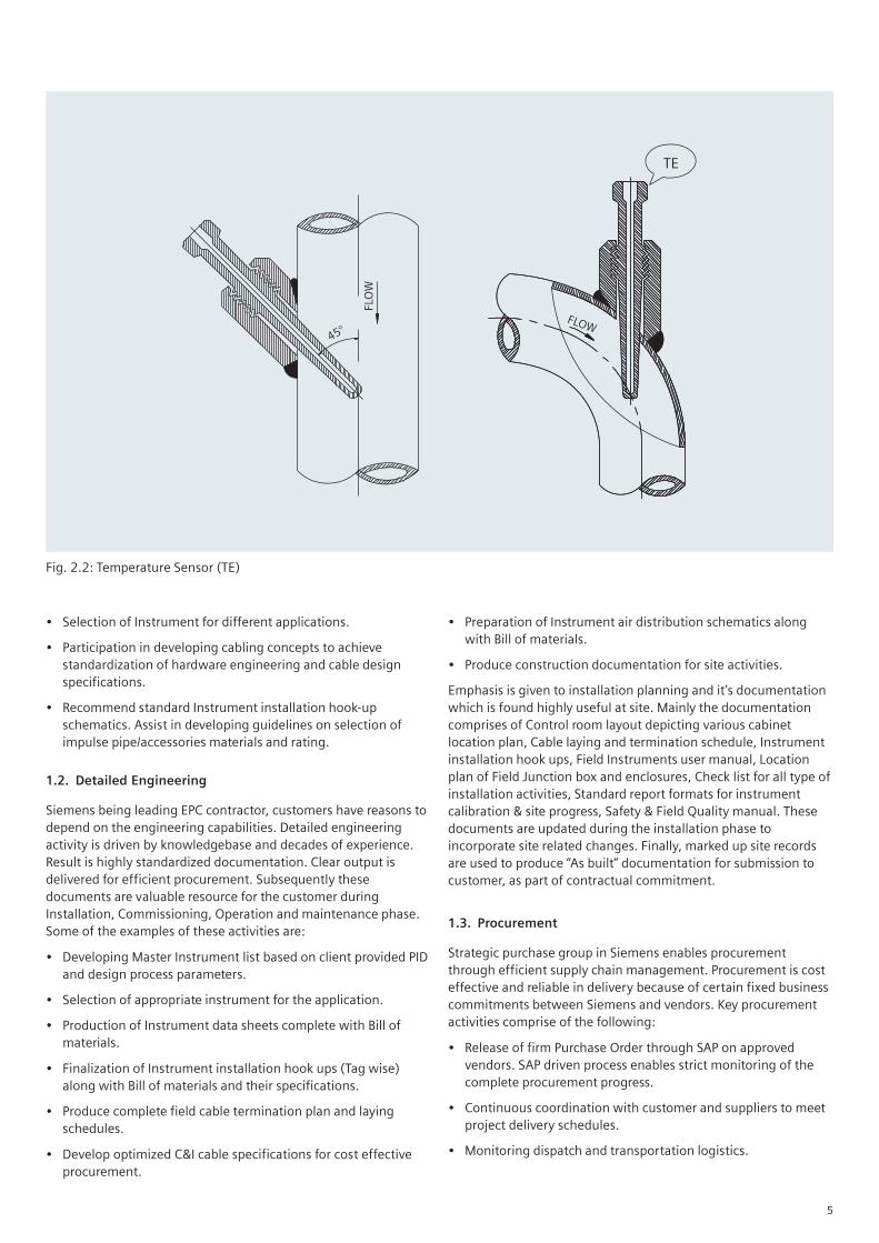
1.4. Quality Control
Quality is synonymous with Siemens. Irrespective of the statedquality requirement in the project, every activity, deliveredmaterial and services has to pass through Quality Gates as per PMprocesses. Projects are executed as per the Project ManagementProcess guide lines ensuring quality check at every critical stage.Delivering high quality equipments is one of the Siemenscorporate quality objectives. Following are some of the examplesin the direction:
• Engineering and Inspection of Instrumentation packages isdone based on knowledge and time proven procedures.
• Manufacturing release is driven by Siemens approved vendor’sQAP.
• In stage inspection is a standard procedure duringmanufacturing phase of the equipments.
• Pre dispatch inspection is imperative. Equipments cannot bedispatched in non compliant way, is the internal requirement.Participation during final inspection is customer’s choice.
1.5. Site Management
Providing professional Site Management services to the esteemedcustomers is Siemens inherent strength, being a leading EPCcontractor. Qualified and experienced personnel are deployed forproject and site management activities. Every site activity done isbased on time tested methodology and continually updatedprocedures. Efforts result in conducting, monitoring and reportingof I&C activities in professional manner. Brief details of the variousundertaken activities are as follows.
• Development of Installation and commissioning documents.
• Preparation of time schedules.
• Materials and store management.
• Calibration of Instruments and maintaining reports.
• Supervision of site activities as per Siemens internal FieldQuality Plan.
• Strict implementation of personnel safety norms during routineactivities.
• Preparation of site progress report, to be used by ProjectManager and for customer update.
• Tracking I&C progress through protocol preparation.
• Coordination with customer at site to schedule and prioritiesactivity to meet project mile stones
• Finalization of the construction documents for handing over tocustomer.
• Handing over of plant to customer for operation.
• Inventory reconciliation statements and site closure.
1.6. Warranty and After sales service
Many times Instruments are offered from different manufacturersto meet complex requirement of power plant instrumentation.Customer require single window interface who meets thewarranty obligation in terms of consumables, spare parts andrepairs services. Siemens provide strong support to fulfill thecustomer’s expectation during the committed warranty period. Inorder to provide this service Siemens organization supports adedicated team of service engineers who take over the projectfrom Project management group to attend warranty calls. Further,this group also provides after sales support i.e., beyond warrantyperiod, depending on customer’s need. Such services areavailable round the clock either remotely or by providing full timedeputation of service engineer at site.
1.7. Offered Instrumentation packages
Broadly, services are offered for the following instruments/packages:-
• Process Transmitters and Switches for pressure, flow, level,temperature measurement
• Temperature sensors - T/C, RTD
• Flow sensors – Orifice plate assembly, Flow nozzle / ventury,Impact head flow meter, Rota meter, Magnetic and Ultrasonicflow meter
• Level sensor- Ultrasonic and Radar type
• Steam and Water Analysis System
• Analyzers for Continuous Emission Monitoring
• Ambient air Quality Monitoring System
• Furnace Flame Monitoring System
• Furnace Flame Camera system
• Furnace Temperature Monitoring System
• Boiler Tube Leak Detection System
• Vibration Monitoring System
• Turbine Supervisory Instrumentation (TSI)
• Close Circuit Television System
• Public Address System
• Power supply System – UPS, Charger, Battery bank
• Control and Instrumentation cables
• Enclosure and Racks for field instruments
• Impulse piping complete with valves, manifold, fittings,siphon, snubber, condensate pot, dust chamber etc.
• Instrument air distribution system
• Cable trays

7
2. Instrumentation - Key packages
Some of the Instrumentation packages are specific to the plantequipment application where as other packages are common tothe entire power plant process. Prominently the Instrumentationpackages can be divided in three categories, for betterunderstanding of the subject. These are related to
• Steam generator
• Turbo generator
• Common to the plant
2.1. Steam generator
Huge pressing demands of energy at base load has set trend tobuild large capacity power generation plants. Installation of largecapacity unit in multiple numbers can only be the answer to theemerging challenge. Continuous availability of the SteamGenerator under varying fuel quality level and operatingconditions need to be reckoned while deciding on the type ofInstrumentation solution. In corollary to human body where eyeand ear provide input to mind, similarly Instrumentation of steamgenerator collects information on internals of the furnace andenables control system for appropriate action. In addition, thisinformation is proactively used for scheduling maintenance, avoidabrupt shut down and increase plant availability.
Fig. 3: Boiler Tube Leakage Detection
Steam generator specific packages are:
2.2. Boiler Tube Leak Detection system (BTLD)
Enables monitoring and early detection of boiler tube leakage inwater walls. Air borne noise, emanating from water wall tubeleak, is picked up by acoustic sensors as an early warning signal.Noise developed from boiler’s fatigued structure is also detectableby another type of acoustic transducer. Information provided bythe system is useful for scheduling maintenance. Advantage tothe utility is eliminating generation loss and expensivemaintenance caused by severe tube leakage or structural failuredetected in advanced stage. Typical system schematic is depictedby Fig-3.
2.3. Furnace Temperature Monitoring System (FTMS)
System provides information on thermal profile of the flue gas inside the furnace. Commonly recommended location formonitoring the temperature is at the furnace and economizer exitpoint in the steam generator. Details are made available in theform of thermal image at the point of monitoring. Acousticsensors (transceivers) are installed in required numbers,depending on the boiler design. These sensors pick up thethermal behavior of the flue gas constituents which has direct

8
2.5. Furnace Flame Monitoring System
Furnace flame monitoring is an essential component of BoilerManagement System. Requirement to monitor furnace flamebegins from the first step to successfully establish flame inside thefurnace by lighting oil/gas and subsequently building up full loadfiring where coal is the main fuel. Flame monitoring scanners aredeployed to establish “Flame” or “No flame” status inside theboiler under all the operating conditions. Based on theinformation provided by the scanners, boiler operation safetylogic is built according to the manufacturer specifications.
Flame scanners task, after establishing flame, is to subsequentlyprovide authentic information on existence of the subject flamebased on discrimination capability w.r.t., adjacent flame orambience sources. Combination of flicker frequency and intensitysignal of the subject flame is the criteria to discriminate with otherilluminated sources. Scanners performance is adjudged by thediscriminating and flame evaluation capability under various typeof conditions prevailing inside the furnace e.g., variations in thefuel quality like dust contents, high humidity level during rainyseason, fly ash surrounding flame zone to name a few. Suchgathered information through the scanners system enables theoperators to decide on course of action to be taken for regulatingthe firing to meet generation target.
Scanner sensing head is suitable for monitoring UV/Visible/IRsource of light. Suitable type of scanners needs to be selecteddepending on the type of fuel firing to be monitored. Smartscanners capable of flame evaluation based on FFT (Fast FourierTransforms) intelligence are available. Inputs provided by theflame scanners also help in improving combustion efficiency ofthe boilers. Typical schematic is depicted by Fig-6.
Fig. 4: Sensors Location Plan
relation to the heat energy carried by them. Data gathered by thesensors help in plotting thermal profile at the monitoring crosssection of the boiler. Study of the thermal image pattern depictsuniformity or imbalance of flue gas heat distribution inside theboiler. Corrective action is taken by control system to change thegun firing combinations so that heat is uniformly distributedthroughout the flue gas path. Uniform heat distributed by the Fluegas improves heat exchangers performance to super heat thesteam.
System also helps in providing information on possible hot spotsinside the furnace which can lead to boiler tubes failure caused byoverheating. Further, Combustion control loop can be fine tunedby using the information provided by the system. Typicalschematic is depicted by Fig-4.
2.4. Furnace Camera System
System monitors the fuel flame pattern inside the boiler furnaceby directly looking at it. Data collected by the camera is used toplot heat dissipation pattern from the flame formed inside thefurnace zone. Adverse information picked up by the system canbe used by control system to take corrective action to balance outthe flame formation. Complementary information on hot spotsand boiler tube condition can also be observed by the cameras.Typical system schematic is depicted by Fig-5.

9
Fig. 5: Furnace Camera System
Fig. 6: Furnace Flame Monitoring System

10
2.6. Turbo Generator
Turbo generator specific Instrumentation package is:
Turbine Supervisory Instrumentation (TSI)
Most critical Instrumentation need in the entire power plant,beyond debate, is to monitoring operating condition of theTurbine Generator machine. TG set is extremely fast actingmachine and operates under thin tolerance band. Sluggish controlof the machine can lead to devastating situation exposing humanlife to unprecedented danger. Fine control and safe operation ofthe TG set is dependent on the information provided by TSIdeployed to monitor the operating conditions of the machine.Therefore, importance of right selection of TSI can be wellunderstood by one and all in power plant environment.
Function of the TSI is to closely monitor the operating parametersof the TG set under all operating conditions i.e., right from a) Coldstart up to synchronization; b) Load ramp up to load throw off; c)Hot role back to load change; d) Normal running to trip condition,are some of the routine situation in power plant. Instrumentsselected shall be sensitive to situation change and report it to the
Fig. 7: Turbine Supervisory Instrumentation
control system quickly for corrective action. Also informationgathered by the system is useful to the experts to do online healthmonitoring and diagnosis of the running machine.
Information on machine operating close to or crossing operatinglimits is provided by the system for operator action. Informationprovided by the system is also used to schedule the preventivemaintenance.
Typical measurement associated with TG set are Rotor shaft andbearing vibration, Differential expansion of rotor and casing,Casing expansion, Thrust bearing pressure, Rotor eccentricity, Keyphaser and Temperature monitoring of Bearing, Turbine casing,Generator winding, Governor valve position. Turbine speedmonitoring is most important parameter for turbine protectioninterlock which is measured with multiple redundant sensors.
Siemens being leading manufacturer of the turbo-generatorsworldwide, genuinely understands the imperatives of conditionmonitoring needs of the machine. Therefore, TSI solution offeredby the Siemens is comprehensive and comes with lot ofinnovative value addition for the customers benefit. Typicalschematic is depicted by Fig-7.

11
Instrumentation packages elaborated below are common to theentire plant.
3.1. Process Transmitters
are used to generate analog signals to monitor various processvalues such as Pressure, Level, Flow etc. Transmitters can bemounted local or remote to the process. Care needs to be taken sothat range selected of the transmitter is suitable to cover entirespectrum of the operating conditions. Right from cold start up toextremely disturbed process condition related measurement shallfall with in the selected range, is the right approach
3.3. Temperature sensor
Thermocouple and RTD are the most commonly used devices.Different types of thermocouple and RTD are available to choosefrom, depending on the process temperature and locationenvironment. Mechanical design of the process stub, Thermowelldesign and immersion length are extremely important parametersassociated with selection of the temperature sensor. Relaxation inmeeting the stated requirement can lead to accident and may beplant shut down. Location and orientation of the sensor in pipingsystem influences the reliability and accuracy of the measuredsignal.
3.4. Flow Sensor
Mostly these are line mounted devices. Commonly used sensorsare Orifice plate assembly, Flow nozzle, Ventury, Rota meters,Impact head meters, Magnetic and Ultrasonic flow meters.Criterion influencing selection of sensor is Line size, Processmedia, flow rate, Pressure and temperature parameters,permissible pressure drop and measured rangeability.
3. Instrumentation Common to plant
3.2. Process switch
are used to generate binary signals. These signals are indicators ofchange in process conditions to depict either abnormality or apermissive status. Set point differential is important parameterand same shall be selected depending on the process behavior.Low differential is preferred for Level and Temperature signalwhere as high differential is the right choice for Pressure and Flowmeasurement.

12
3.5. Level Sensor
Contemporary sensors for Level measurement are driven by Radaror Ultrasonic based technology. These sensors do not have anymoving parts which make them drift free and reliable inperformance. Displacer or float type sensors are no more thechoice of designers.
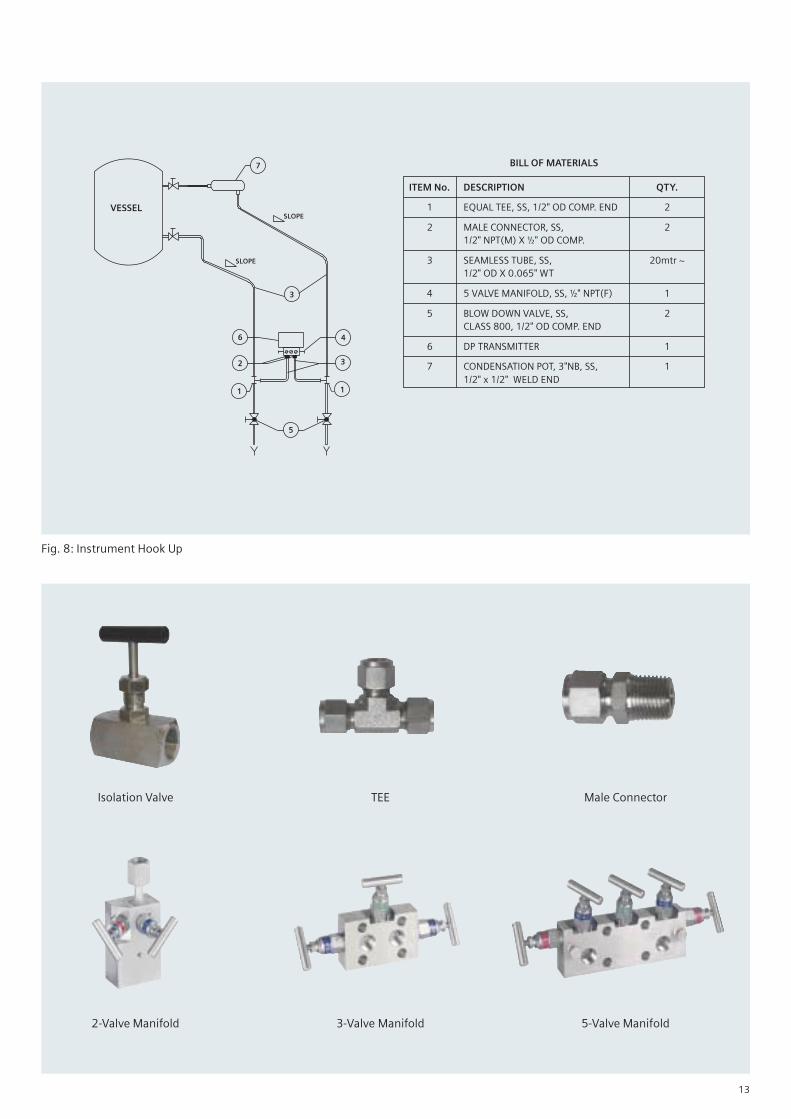
3.7. Instruments Installation Hook ups
Detailed engineering exercise also includes developing Instrumentinstallation hook ups, preparing bill of materials and Installationdrawings for the offered Field Instruments. Hook ups are preparedtag wise. Impulse pipe, tube, instrument valves, manifolds,various types fittings form part of the bill of materials.
Siemens contribution is to recommend field proven hook upschemes, selection of materials according to the pressure andtemperature parameters of the respective tag number andquantification of bill of materials. Design margins of the selectedmaterial of impulse pipe and components is specified inline withthe guidelines of international standards like ANSI, ASME, DIN.Refer Fig-8 as an example of instrument hook up diagram.
Special Instrument installation arrangement for Coal bunker level,CW sump level, Boiler tube leak detection sensor, Furnacetemperature acoustic sensor and Flame scanners are seamlesslycoordinated with mechanical equipment supplier.
3.6. Field Instruments Enclosure and racks
Process transmitters, Switches and local Gauges can be mountedin field installed Enclosures and Racks. Harsh plant environment,protection against inadvertent operation, functional grouping ofinstruments for ease of operation, saving on installation time atsite, are some of the reasons to go for this option. Enclosure andRacks are delivered to site pre-tubed, wired up to integral Junctionbox, hydro tested for safe pressure rating/leakage. These aresuitable for installation at the pre identified locations in the boilerand TG area. Impulse pipe needs to be field routed from processtapping and can be terminated at the enclosure/rack respectiveinterface point.
Field Instrument Rack
Field Instrument Enclosure
13
Isolation Valve TEE Male Connector
2-Valve Manifold 3-Valve Manifold 5-Valve Manifold
Fig. 8: Instrument Hook Up
BILL OF MATERIALS
ITEM No. DESCRIPTION QTY.
1 EQUAL TEE, SS, 1/2" OD COMP. END 2
2 MALE CONNECTOR, SS, 21/2" NPT(M) X ½" OD COMP.
3 SEAMLESS TUBE, SS, 20mtr ~1/2" OD X 0.065" WT
4 5 VALVE MANIFOLD, SS, ½" NPT(F) 1
5 BLOW DOWN VALVE, SS, 2CLASS 800, 1/2" OD COMP. END
6 DP TRANSMITTER 1
7 CONDENSATION POT, 3"NB, SS, 11/2" x 1/2" WELD END

14
3.8. Instrument Air Distribution system
Instrument air requirement for Pneumatic actuators, Air purge toFurnace measurement Transmitters in a coal fired power plant is acommon place in instrumentation package. Wide spreadInstrument air distribution network is needed to meet therequirement. Typical schematic is depicted by Fig-9.
Siemens contribution comprises of developing instrument airconsumers list, air distribution scheme, sizing of air headers,preparation of pneumatic hook ups and material take off.
3.9. Control elements
Control valve, Power cylinder, Solenoid valve are the prominentcontrol elements known in the power plant application. Thesecontrol elements are fitted with Pneumatic, Hydraulic or ElectricActuators depending on the automation requirement. Duty can bemodulation or ON/OFF type. Siemens make of smart positionersare fitted which have nearly zero air consumption in steady stateof operation. Design selection criterion of the control elements isdependent on the following:
• Process medium chemistry for body material selection.
• Design Pressure & Temperature parameters for body rating.
• Operating conditions for Trim design selection.
• Piping interface for end connection.
• Fail safe operating condition
• Interlock and feed back signals requirement for the accessories.
One of the important and critical applications in this family is HPand LP bypass control valves for TG island where Siemens offerexpert solution. Along with HP, LP bypass control valves, solutionincludes control system and complimentary packages.
Combined Aux PRDS station to meet customized requirement isalso engineered and delivered.
3.10. Plant Engineering
Based on the plant layouts, piping isometrics or layout drawingsand PID, Siemens can assist the customers in developingInstruments grouping for Field Junction box and InstrumentEnclosure/Racks according to functional requirement. Locationplans are also recommended keeping in mind the ease ofoperation and maintenance activities.
3.11. Vital Power supply system
Normally two types of power supply systems needed forautomation system are:
• 1 phase, 50/60 Hz, 230/110V AC and
• 24V DC
Indeed, Power supply system is the life line of automation systemengaged in monitoring and controlling the power plantgeneration. Therefore, reliability of the power supply system is ofparamount importance.
Fig. 9: Instrument Air Distribution
Smart Positioner
SIPART PS2

15
3.12. Uninterrupted Power Supply system
Broadly 1 phase, 50/60 Hz, 230/110V AC power supply is requiredto power operating and monitoring system. Good UPS systemprovides reliable and quality power supply in uninterruptedmanner. Quality of UPS output is adjudged by the regulationtolerance of Voltage, wave formation, frequency, transient loadchange variations etc. to be better than the specifications of theconnected loads.
Parallel redundant with maintenance bypass is a well acceptedUPS configuration. System normally operates in equal loadsharing mode. Failure of one UPS stream bump less transfer the100% load to the second stream. Common battery bank is the lastresource to deliver power supply. Bypass line can be cut in to feedthe demand under scheduled maintenance period of UPS. Bypassconnection is established in make before break manner to avoidany brown outs. Isolating transformers are provided to arrest thefault arising from loads or UPS to protect higher level of rawpower supply system. Refer Fig-10 for single line diagram ofparallel redundant UPS.
3.13. Charger system - 24V DC power supply
Automation system power supply requirement is generally of 24VDC. Rectifier cum chargers complete with battery bank fulfills therequirement. SMPS based rectifiers is the favorite choice of thedesigners because of the higher overall efficiency. Dual parallelconfiguration with common battery bank is common in demand.Besides feeding the loads, chargers also provide window to boostor float charge the batteries.
3.14. Battery bank
Depending on customer’s choice, batteries can be maintenancefree Lead Acid or NiCad type. Single or block cells can be offeredaccording to the available space. Battery health monitoringsystem is integral part of the battery bank. Health monitoring isdone at each cell level and information can be interfaced tocontrol room for operator’s information.
Battery bank engineered by Siemens has in built provision to caterfull load requirements under all operating conditions for the lifetime of the power plant. While sizing the battery bank, aging,design margin, temperature compensation etc are factored in todeliver robust solution.
3.15. Water chemistry
Requirement of water and steam in power plant processes is of aspecific quality. Health and availability of the power plantequipments is directly influenced by the contamination level ofthe water and steam quality. Higher level of contamination simplydeteriorate the power plant overall efficiency. Conductivity, pH,Dissolved oxygen, Residual Sodium and Hydrazine, DissolvedSilica, Hydrogen are the main constituents to be monitored andcontrolled in water and steam cycle.
Stated measurements are monitored online on continuous basis.Preferred concept is to collect samples at a central place nearcontrol room in chemist’s laboratory. These samples need to beconditioned in terms of Pressure, Temperature and Flow rate tomeet microprocessor based electronic analyzer requirement, isimportant factor in system design and engineering.
Fig. 10: SLD of Parallel Redundant Ups
16
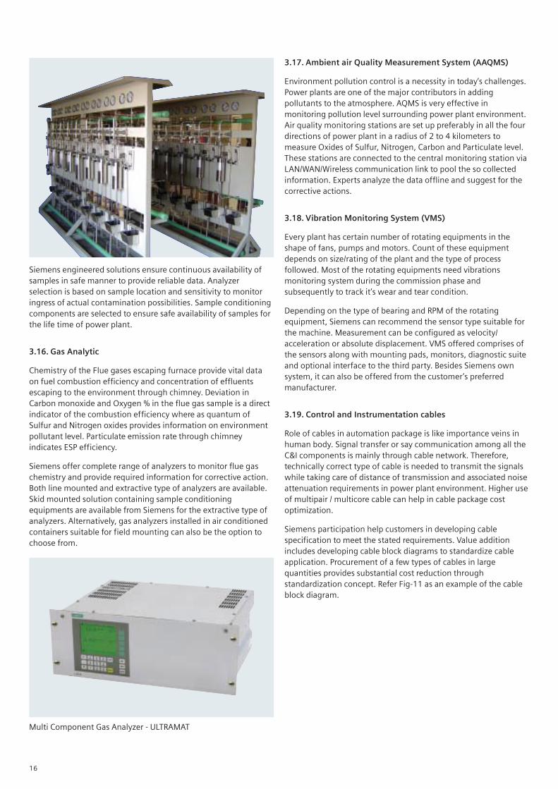
Siemens engineered solutions ensure continuous availability ofsamples in safe manner to provide reliable data. Analyzerselection is based on sample location and sensitivity to monitoringress of actual contamination possibilities. Sample conditioningcomponents are selected to ensure safe availability of samples forthe life time of power plant.
3.16. Gas Analytic
Chemistry of the Flue gases escaping furnace provide vital dataon fuel combustion efficiency and concentration of effluentsescaping to the environment through chimney. Deviation inCarbon monoxide and Oxygen % in the flue gas sample is a directindicator of the combustion efficiency where as quantum ofSulfur and Nitrogen oxides provides information on environmentpollutant level. Particulate emission rate through chimneyindicates ESP efficiency.
Siemens offer complete range of analyzers to monitor flue gaschemistry and provide required information for corrective action.Both line mounted and extractive type of analyzers are available.Skid mounted solution containing sample conditioningequipments are available from Siemens for the extractive type ofanalyzers. Alternatively, gas analyzers installed in air conditionedcontainers suitable for field mounting can also be the option tochoose from.
3.17. Ambient air Quality Measurement System (AAQMS)
Environment pollution control is a necessity in today’s challenges.Power plants are one of the major contributors in addingpollutants to the atmosphere. AQMS is very effective inmonitoring pollution level surrounding power plant environment.Air quality monitoring stations are set up preferably in all the fourdirections of power plant in a radius of 2 to 4 kilometers tomeasure Oxides of Sulfur, Nitrogen, Carbon and Particulate level.These stations are connected to the central monitoring station viaLAN/WAN/Wireless communication link to pool the so collectedinformation. Experts analyze the data offline and suggest for thecorrective actions.
3.18. Vibration Monitoring System (VMS)
Every plant has certain number of rotating equipments in theshape of fans, pumps and motors. Count of these equipmentdepends on size/rating of the plant and the type of processfollowed. Most of the rotating equipments need vibrationsmonitoring system during the commission phase andsubsequently to track it’s wear and tear condition.
Depending on the type of bearing and RPM of the rotatingequipment, Siemens can recommend the sensor type suitable forthe machine. Measurement can be configured as velocity/acceleration or absolute displacement. VMS offered comprises ofthe sensors along with mounting pads, monitors, diagnostic suiteand optional interface to the third party. Besides Siemens ownsystem, it can also be offered from the customer’s preferredmanufacturer.
3.19. Control and Instrumentation cables
Role of cables in automation package is like importance veins inhuman body. Signal transfer or say communication among all theC&I components is mainly through cable network. Therefore,technically correct type of cable is needed to transmit the signalswhile taking care of distance of transmission and associated noiseattenuation requirements in power plant environment. Higher useof multipair / multicore cable can help in cable package costoptimization.
Siemens participation help customers in developing cablespecification to meet the stated requirements. Value additionincludes developing cable block diagrams to standardize cableapplication. Procurement of a few types of cables in largequantities provides substantial cost reduction throughstandardization concept. Refer Fig-11 as an example of the cableblock diagram.
Multi Component Gas Analyzer - ULTRAMAT

17
3.20. CCTV system
Considering vast expanse of power plant premise and accessdifficulty in attending all the plant machinery, it is extremelychallenging to arrange for round the clock surveillance all over bydeploying personnel. Event capturing and monitoring difficultlocations in power plant can be effectively managed by installingClose Circuit TV system at the pre identified locations. Entire
station can be under surveillance from central monitoring controlroom where operators can keep watch round the clock.
Event capturing can be pre engineered to arrest happeningsequence with pan tilt and zoom functions for each cameralocation. Data collected from all the cameras can be used forinstant analysis or can be archived for future use. Refer Fig-12 forsystem configuration of CCTV.
Fig. 11: Cable Block Diagram
Fig. 12: System Configuration CCTV
18
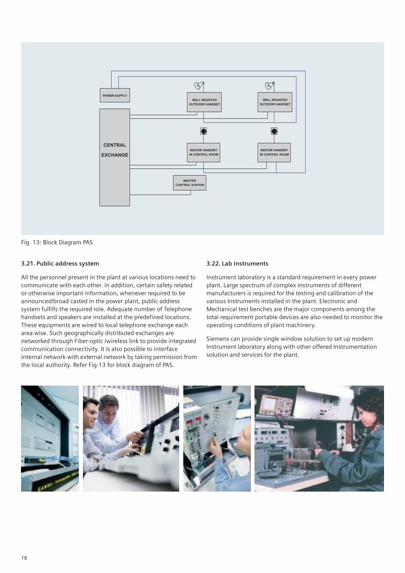
3.21. Public address system
All the personnel present in the plant at various locations need tocommunicate with each other. In addition, certain safety relatedor otherwise important information, whenever required to beannounced/broad casted in the power plant, public addresssystem fulfills the required role. Adequate number of Telephonehandsets and speakers are installed at the predefined locations.These equipments are wired to local telephone exchange eacharea wise. Such geographically distributed exchanges arenetworked through Fiber-optic /wireless link to provide integratedcommunication connectivity. It is also possible to interfaceinternal network with external network by taking permission fromthe local authority. Refer Fig-13 for block diagram of PAS.
3.22. Lab Instruments
Instrument laboratory is a standard requirement in every powerplant. Large spectrum of complex instruments of differentmanufacturers is required for the testing and calibration of thevarious Instruments installed in the plant. Electronic andMechanical test benches are the major components among thetotal requirement portable devices are also needed to monitor theoperating conditions of plant machinery.
Siemens can provide single window solution to set up modernInstrument laboratory along with other offered Instrumentationsolution and services for the plant.
Fig. 13: Block Diagram PAS

19
3.23. Miscellaneous packages
Some of the complementary packages falling betweenInstrumentation and Control system are also offered for specificapplications.
– Field Interface Modules (FIM) are available to providecustomized signal conditioning functions for the fieldgenerated signals to make them compatible to the controlsystem. FIM is a compact electronic module suitable for DIN railmounting. Typical functionality provided by the FIM is asfollows:
• Signal multiplication of single field sensor output forredundancy purpose.
• Provision of optical/electrical isolation between field signalsand control system.
• Field signal isolation through knife switches for testingpurpose during commissioning phase.
• Compact Power supply distribution (24V DC) for automationsystem.
• Diode auctioneering for redundant power supply feeders.
• Interface between high voltage (110V/220V AC) field inputto low voltage (24V DC) control system signal.
• Any other customized application can be offered
– Control room furniture for the Control system.
– Development of customized control panels.
3.24. International Standards
Design engineering of various instrumentation packages is donein accordance with International Standards; IEC, IEEE, ANSI, ASME,DIN. These products are delivered with UL, CE certificationdepending on application. Any other conformance according toapplication specific need can also be considered during thedesign engineering phase.
Installation & commissioning is carried out in line with jointlyaccepted Field Quality Plan. Special emphasis is given topersonnel safety working at site. Audit check by certifiedengineers related to installation practices & personnel safety is aroutine activity.
4. Inference
Instrumentation solutions offered by Siemens are comprehensive,world class and tailored to meet power plant specific needs.Return on customer’s investment is rewarded instantly throughthe cost effective bulk procurement efforts by Supply chain
management group. Professional approach of ProjectManagement Procedures ensures timely delivery to meet projectmile stones. The biggest advantage to the customer is:
“Siemens offer One Stop Shop Solution for all Power Plant Instrumentation needs”.

Customer Care Toll free no. 1800 419 7477Email: [email protected] Product upgradation is a continuous process. Hence, data in
this catalog is subject to change without prior notice. For thelatest information, please get in touch with our Sales Offices.
www.siemens.co.in
Regional Sales Offices
NORTH - GurgaonSiemens Ltd.Energy sector3rd Floor, Plot 6A, Sector 18,Maruti Industrial AreaGurgaon, Haryana - 122015IndiaContact Person: Mr. I.K. RaiTel. (Dir.): +91 124 4697376Mobile: +91 9818018701E-mail: [email protected]
WEST - MumbaiSiemens Ltd.Energy sector3rd Floor, R&D Tech Centre,Thane Belapur Road, Thane - 400601IndiaContact Person: Mr. Sachin Jaguste / Mr. Neenad WilankarTel. (Dir.): +91 22 24987341Mobile: +91 9819155056E-mail: [email protected]: +91 9867665588E-mail: [email protected]
WEST - BarodaSiemens Ltd.Energy sector3rd Floor, Ohm Business ParkOpp. Balaji Hospital, Ellora ParkSubhanpura, Vadodara - 23Gujarat, IndiaContact Person: Mr. Mandar PagedarTel. (Dir.): +91 265 6692123Mobile: +91 9925004384E-mail: [email protected]
Contact Person: Mr. Kuldeep Tickoo / Mr. Aditya DubeyE-mail: [email protected],
EAST - KolkataSiemens Ltd.Energy sector43, ShantipalliEastern Metropolitan BypassR B connector, KolkattaWest Bengal - 700042IndiaContact Person: Mr. Ashoke RoyTel. (Dir.): +91 33 24449000Mobile: +91 9830006653E-mail: [email protected]
SOUTH - ChennaiSiemens Ltd.Energy sector144, Mahatma Gandhi RoadChennai (Madras)Tamil Nadu- 600034IndiaContact Person: Mr. Muralidharan KrishnanTel. (Dir.): +91 44 28334608Mobile: +91 9962592826E-mail: [email protected]
For any Technical Documentation, pls visitwww.siprotec.comwww.reyrolle-protection.com
For any general queries and technical support, pls write to us [email protected]
Siemens Ltd.Energy Sector - FossilPlot - 6A, Sector - 18, Maruti Industrial AreaHuda, Gurgaon - 122 015.Tel.: +91 124 2846000Fax: +91 124 2846141E-mail: [email protected]