Embed Size (px)
Citation preview
SSP-PRC001-ENAugust 2005
Split System Heat Pumps
Split System Heat Pumps
7 1/2 - 20 Tons - 60 Hz
Air Handlers
5 - 20 Tons - 60 Hz
©2004 American Standard Inc. All rights reserved. SSP-PRC001-EN
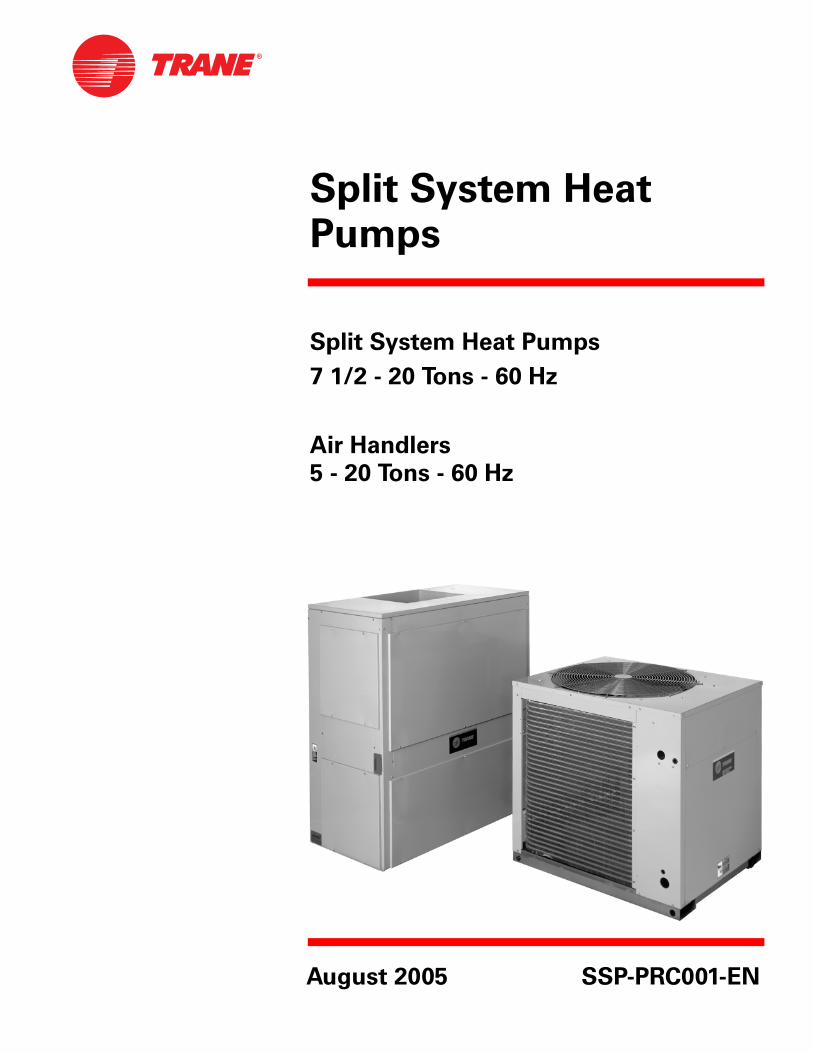
The Trane reputation for quality and reliability in air conditioning is appar-ent with Odyssey™ light commercial split systems. These Trane systems are designed to meet your job requirements every time...and at a competitive price.
Odyssey has Trane quality and reli-ability built-in; couple that with out-standing efficiency, flexibility and installation ease and you have an unbeatable combination for years of worry-free service and operation.
Manufacturing Control Trane’s exclusive control over the design and manufacturing of all major components is unique in the industry. This approach assures us total control over both the quality and reliability of these components. And allows us to custom match components to deliver the best in split system performance.
Designing the Details Careful attention was given to design-ing the details — from control wiring to the access panels. Odyssey units feature time-saving colored and num-bered wiring and removable panels which allow complete access to all major components and controls. All outdoor units feature external high and low pressure switches for easy diagnosing and servicing of the unit. Service valves with gauge ports are provided on all units.
Standardized Cabinets In addition, all cabinets have been standardized. When you are servicing an outdoor unit or an air handler, all components are in the same location from unit to unit.
Introduction
Split System Heat Pump Units . . . Designed With Your Needs In Mind.
Filters The 5, 7½ and 10 ton air handlers are supplied with 1" throwaway filters as standard. The filter racks were designed to easily convert for installa-tion of 2" filters. The 15 and 20 ton air handlers have 2" filters as standard.
UL Listed and ARI Certified Trane meets or exceeds all nationally recognized agency safety and design standards. Each condensing unit is UL designed, approved and labeled in ac-cordance to UL Standards: UL 1995 for central cooling air conditioners, refrig-eration and air conditioning condens-ing and compressor units. Each air handler is designed, approved and la-beled in accordance to UL 465 and UL 1995 standard for heat pumps. Each unit is certified in accordance with ARI Standard 340/360.
SSP-PRC001-EN 3
Table of Contents
Introduction 2
Features and Benefits 4
Application Considerations 6
Selection Procedures 7Model Number Description 8
General Data 9
Performance Data 11Cool and Heat Performance 11
Fan Performance 21
Controls 30
Electrical Power 31
Dimensional Data 41
Mechanical Specifications 55
4 SSP-PRC001-EN
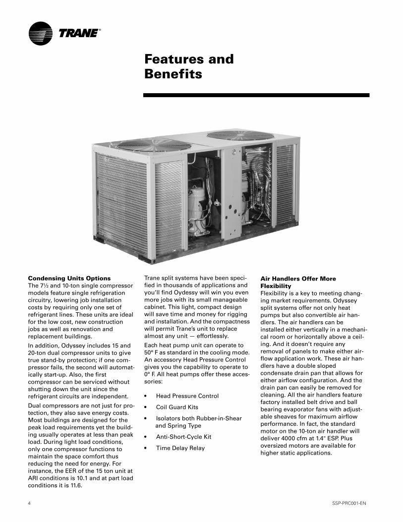
Condensing Units Options The 7½ and 10-ton single compressor models feature single refrigeration circuitry, lowering job installation costs by requiring only one set of refrigerant lines. These units are ideal for the low cost, new construction jobs as well as renovation and replacement buildings.
In addition, Odyssey includes 15 and 20-ton dual compressor units to give true stand-by protection; if one com-pressor fails, the second will automat-ically start-up. Also, the first compressor can be serviced without shutting down the unit since the refrigerant circuits are independent.
Dual compressors are not just for pro-tection, they also save energy costs. Most buildings are designed for the peak load requirements yet the build-ing usually operates at less than peak load. During light load conditions, only one compressor functions to maintain the space comfort thus reducing the need for energy. For instance, the EER of the 15 ton unit at ARI conditions is 10.1 and at part load conditions it is 11.6.
Trane split systems have been speci-fied in thousands of applications and you’ll find Oydessy will win you even more jobs with its small manageable cabinet. This light, compact design will save time and money for rigging and installation. And the compactness will permit Trane’s unit to replace almost any unit — effortlessly.
Each heat pump unit can operate to 50° F as standard in the cooling mode. An accessory Head Pressure Control gives you the capability to operate to 0° F. All heat pumps offer these acces-sories:
• Head Pressure Control
• Coil Guard Kits
• Isolators both Rubber-in-Shear and Spring Type
• Anti-Short-Cycle Kit
• Time Delay Relay
Air Handlers Offer More FlexibilityFlexibility is a key to meeting chang-ing market requirements. Odyssey split systems offer not only heat pumps but also convertible air han-dlers. The air handlers can be installed either vertically in a mechani-cal room or horizontally above a ceil-ing. And it doesn’t require any removal of panels to make either air-flow application work. These air han-dlers have a double sloped condensate drain pan that allows for either airflow configuration. And the drain pan can easily be removed for cleaning. All the air handlers feature factory installed belt drive and ball bearing evaporator fans with adjust-able sheaves for maximum airflow performance. In fact, the standard motor on the 10-ton air handler will deliver 4000 cfm at 1.4" ESP. Plus oversized motors are available for higher static applications.
Features andBenefits
SSP-PRC001-EN 5
Odyssey air handler versatility is fur-ther increased by a complete line of accessories designed to match and install smoothly:
• Discharge Plenum and Grille
• Return Grille
• Subbase
• Electric Heaters
• High Static Evaporator Motor
• Isolators both Rubber-in-Shear and Spring Type
• A Full Line of Thermostats
• Outdoor Thermostat
Odyssey — A CompleteSplit SystemOdyssey delivers the flexibility to select a complete system that meets your particular job requirements. Air handlers are designed, tested, and rated with outdoor units to let you select the proper match between capacity and load. Heat pumps can also be matched with Trane built-up air handlers. Also, these matched sys-tems can be quickly engineered for specific applications using Trane’s computerized selection and load pro-grams.
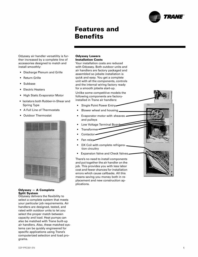
Odyssey Lowers Installation Costs Your installation costs are reduced with Odyssey. Both outdoor units and air handlers are factory packaged and assembled so jobsite installation is quick and easy. You get a complete unit with all the components, controls and the internal wiring factory ready for a smooth jobsite start-up.
Unlike some competitive models the following components are factory-installed in Trane air handlers:
• Single Point Power Entry
• Blower wheel and housing
• Evaporator motor with sheaves and pulleys
• Low Voltage Terminal Board
• Transformer
• Contactor
• Fan relay
• DX Coil with complete refrigera-tion circuitry
• Expansion Valve and Check Valves
There’s no need to install components and put together the air handler on the job. This provides you with less labor cost and fewer chances for installation errors which cause callbacks. All this means saving you money both in re-placement and new construction ap-plications.
Features andBenefits
6 SSP-PRC001-EN
Application of this product should be within the catalogued airflow and per-formance considerations.
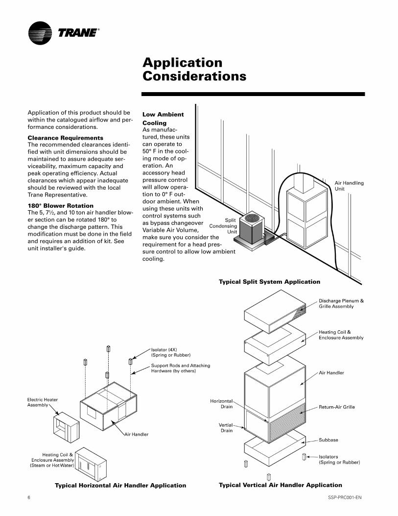
Clearance RequirementsThe recommended clearances identi-fied with unit dimensions should be maintained to assure adequate ser-viceability, maximum capacity and peak operating efficiency. Actual clearances which appear inadequate should be reviewed with the local Trane Representative.
180° Blower RotationThe 5, 7½, and 10 ton air handler blow-er section can be rotated 180° to change the discharge pattern. This modification must be done in the field and requires an addition of kit. See unit installer's guide.
Low Ambient CoolingAs manufac-tured, these units can operate to 50° F in the cool-ing mode of op-eration. An accessory head pressure control will allow opera-tion to 0° F out-door ambient. When using these units with control systems such as bypass changeover Variable Air Volume, make sure you consider the requirement for a head pres-sure control to allow low ambient cooling.
ApplicationConsiderations
Typical Horizontal Air Handler Application Typical Vertical Air Handler Application
Typical Split System Application
SSP-PRC001-EN 7
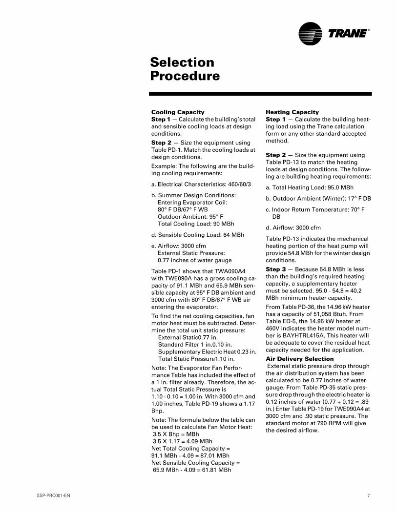
Cooling CapacityStep 1 — Calculate the building’s total and sensible cooling loads at design conditions.
Step 2 — Size the equipment using Table PD-1. Match the cooling loads at design conditions.
Example: The following are the build-ing cooling requirements:
a. Electrical Characteristics: 460/60/3
b. Summer Design Conditions:Entering Evaporator Coil: 80° F DB/67° F WBOutdoor Ambient: 95° FTotal Cooling Load: 90 MBh
d. Sensible Cooling Load: 64 MBh
e. Airflow: 3000 cfmExternal Static Pressure:0.77 inches of water gauge
Table PD-1 shows that TWA090A4 with TWE090A has a gross cooling ca-pacity of 91.1 MBh and 65.9 MBh sen-sible capacity at 95° F DB ambient and 3000 cfm with 80° F DB/67° F WB air entering the evaporator.
To find the net cooling capacities, fan motor heat must be subtracted. Deter-mine the total unit static pressure:
External Static0.77 in.Standard Filter 1 in.0.10 in.Supplementary Electric Heat 0.23 in.Total Static Pressure1.10 in.
Note: The Evaporator Fan Perfor-mance Table has included the effect of a 1 in. filter already. Therefore, the ac-tual Total Static Pressure is 1.10 - 0.10 = 1.00 in. With 3000 cfm and 1.00 inches, Table PD-19 shows a 1.17 Bhp.
Note: The formula below the table can be used to calculate Fan Motor Heat: 3.5 X Bhp = MBh 3.5 X 1.17 = 4.09 MBhNet Total Cooling Capacity = 91.1 MBh - 4.09 = 87.01 MBhNet Sensible Cooling Capacity = 65.9 MBh - 4.09 = 61.81 MBh
Heating CapacityStep 1 — Calculate the building heat-ing load using the Trane calculation form or any other standard accepted method. Step 2 — Size the equipment using Table PD-13 to match the heating loads at design conditions. The follow-ing are building heating requirements:
a. Total Heating Load: 95.0 MBh
b. Outdoor Ambient (Winter): 17° F DB
c. Indoor Return Temperature: 70° F DB
d. Airflow: 3000 cfm
Table PD-13 indicates the mechanical heating portion of the heat pump will provide 54.8 MBh for the winter design conditions.
Step 3 — Because 54.8 MBh is less than the building’s required heating capacity, a supplementary heater must be selected. 95.0 - 54.8 = 40.2 MBh minimum heater capacity.
From Table PD-36, the 14.96 kW heater has a capacity of 51,058 Btuh. From Table ED-5, the 14.96 kW heater at 460V indicates the heater model num-ber is BAYHTRL415A. This heater will be adequate to cover the residual heat capacity needed for the application.
Air Delivery Selection External static pressure drop through the air distribution system has been calculated to be 0.77 inches of water gauge. From Table PD-35 static pres-sure drop through the electric heater is 0.12 inches of water (0.77 + 0.12 = .89 in.) Enter Table PD-19 for TWE090A4 at 3000 cfm and .90 static pressure. The standard motor at 790 RPM will give the desired airflow.
SelectionProcedure
8 SSP-PRC001-EN
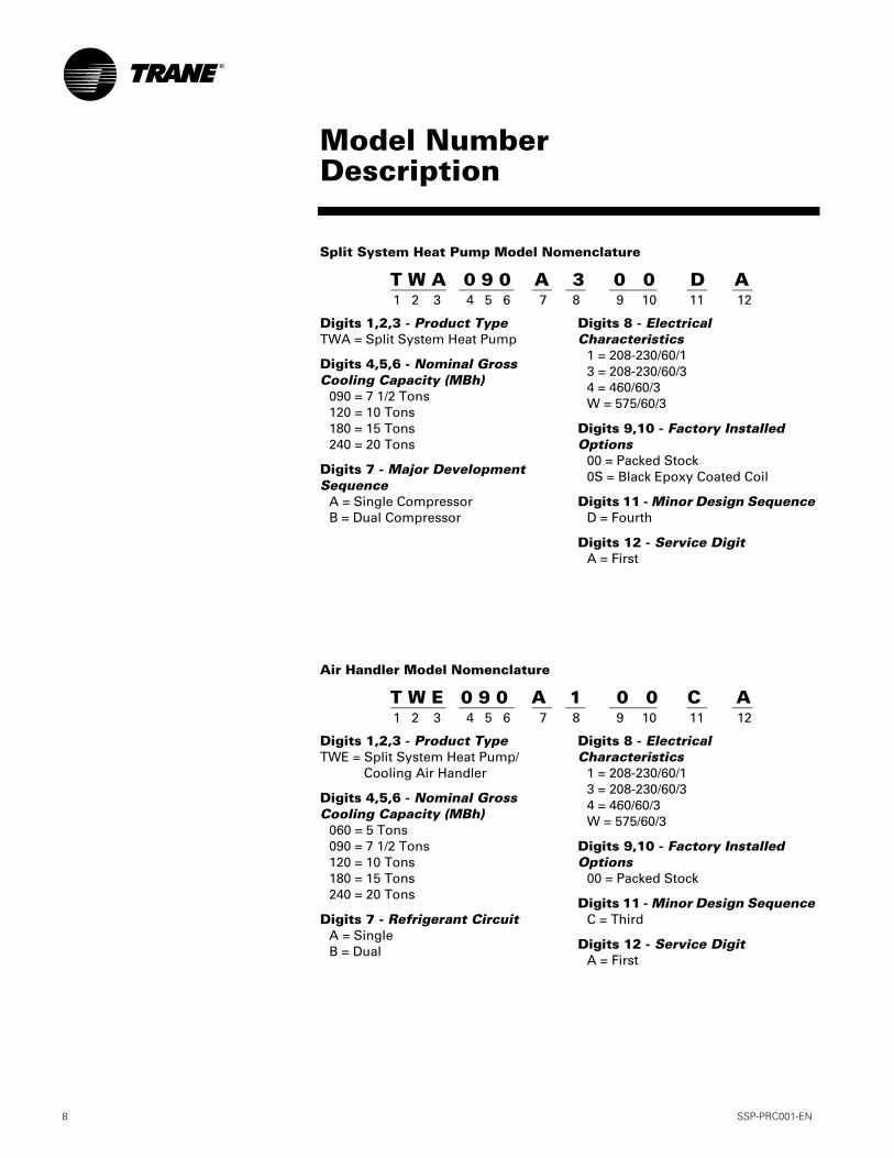
Digits 1,2,3 - Product TypeTWA = Split System Heat Pump
Digits 4,5,6 - Nominal Gross Cooling Capacity (MBh)
090 = 7 1/2 Tons120 = 10 Tons180 = 15 Tons240 = 20 Tons
Digits 7 - Major Development Sequence
A = Single CompressorB = Dual Compressor
Digits 8 - Electrical Characteristics
1 = 208-230/60/13 = 208-230/60/34 = 460/60/3W = 575/60/3
Digits 9,10 - Factory Installed Options
00 = Packed Stock0S = Black Epoxy Coated Coil
Digits 11 - Minor Design SequenceD = Fourth
Digits 12 - Service DigitA = First
Model NumberDescription
Split System Heat Pump Model Nomenclature
T W A 0 9 0 A 3 0 0 D A1 2 3 4 5 6 7 8 9 10 11 12
Digits 1,2,3 - Product TypeTWE = Split System Heat Pump/
Cooling Air Handler
Digits 4,5,6 - Nominal Gross Cooling Capacity (MBh)
060 = 5 Tons090 = 7 1/2 Tons120 = 10 Tons180 = 15 Tons240 = 20 Tons
Digits 7 - Refrigerant CircuitA = SingleB = Dual
Digits 8 - Electrical Characteristics
1 = 208-230/60/13 = 208-230/60/34 = 460/60/3W = 575/60/3
Digits 9,10 - Factory Installed Options
00 = Packed Stock
Digits 11 - Minor Design SequenceC = Third
Digits 12 - Service DigitA = First
Air Handler Model Nomenclature
T W E 0 9 0 A 1 0 0 C A1 2 3 4 5 6 7 8 9 10 11 12
SSP-PRC001-EN 9
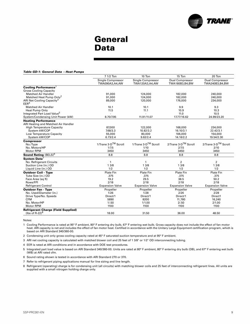
Table GD-1: General Data —Heat Pumps
Notes:
1 Cooling Performance is rated at 95° F ambient, 80° F entering dry bulb, 67° F entering wet bulb. Gross capacity does not include the effect of fan motor heat. ARI capacity is net and includes the effect of fan motor heat. Certified in accordance with the Unitary Large Equipment certification program, which is based on ARI Standard 340/360-00.
2 Condensing unit only gross cooling capacity rated at 45° F saturated suction temperature and at 95° F ambient.
3 ARI net cooling capacity is calculated with matched blower coil and 25 feet of 1 3/8" or 1/2" OD interconnecting tubing.
4 EER is rated at ARI conditions and in accordance with DOE test procedures.
5 Integrated part load value is based on ARI Standard 340/360-00. Units are rated at 80° F ambient, 80° F entering dry bulb (DB), and 67° F entering wet bulb (WB) at ARI rated cfm.
6 Sound rating shown is tested in accordance with ARI Standard 270 or 370.
7 Refer to refrigerant piping applications manual for line sizing and line length.
8 Refrigerant (operating) charge is for condensing unit (all circuits) with matching blower coils and 25 feet of interconnecting refrigerant lines. All units are supplied with a small nitrogen holding charge only.
7 1/2 Ton 10 Ton 15 Ton 20 TonSingle CompressorTWA090A3,A4,AW
Single CompressorTWA120A3,A4,AW
Dual CompressorTWA180B3,B4,BW
Dual CompressorTWA240B3,B4,BW
Cooling Performance1
Gross Cooling CapacityMatched Air HandlerMatched Heat Pump Only2
ARI Net Cooling Capacity3
EER4
Matched Air HandlerHeat Pump Only
Integrated Part Load Value5
System/Condensing Unit Power (kW)
91,00091,00089,000
10.111.5
-8.70/7.95
124,000124,000120,000
10.111.1
-11.91/11.07
182,000182,000176,000
9.910.911.0
17.77/16.62
240,000240,000234,000
9.310.310.5
24.99/23.20Heating PerformanceARI Heating and Matched Air Handler
High Temperature CapacitySystem kW/COP
Low Temperature CapacitySystem kW/COP
87,0007.68/3.355,0006.73/2.4
122,00010.82/3.280,0009.62/2.4
168,00016.10/3.1106,00014.16/2.2
234,00022.42/3.1154,000
19.54/2.30Compressor
No./TypeNo. Motors/HPMotor RPM
1/Trane 3-DTM Scroll1/7.53450
1/Trane 3-DTM Scroll1/103450
2/Trane 3-DTM Scroll2/7.53450
2/Trane 3-DTM Scroll2/103450
Sound Rating (BELS)6 8.8 8.8 8.8 8.8System Data7
No. Refrigerant CircuitsSuction Line (in.) ODLiquid Line (in.) OD
11 3/81/2
11 3/81/2
21 3/81/2
21 3/81/2
Outdoor Coil - TypeTube Size (in.) ODFace Area (sq ft)Rows/FPIRefrigerant Control
Plate Fin.37519.22/18
Expansion Valve
Plate Fin.37529.52/18
Expansion Valve
Plate Fin.37538.52/18
Expansion Valve
Plate Fin.37550.22/18
Expansion ValveOutdoor Fan - Type
No. Used/Diameter (in.)Drive Type/No. SpeedsCFMNo. Motor/HPMotor RPM
Propeller1/26
Direct/158901/.501100
Propeller1/28
Direct/182001/1.001100
Propeller2/26
Direct/111,7802/.501100
Propeller2/28
Direct116,2402/1.001100
Refrigerant Charge (Field Supplied)(lbs of R-22)8 18.00 31.50 36.00 48.50
GeneralData
10 SSP-PRC001-EN
GeneralData
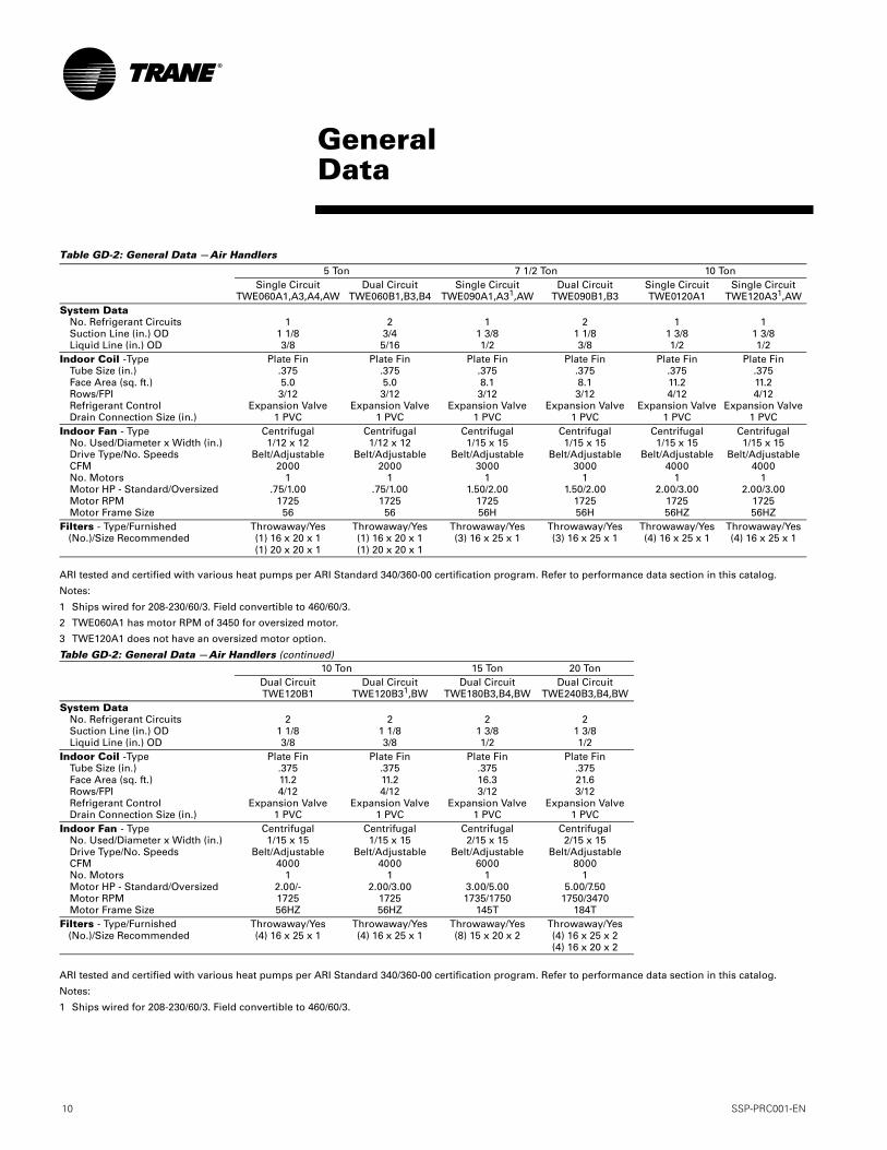
Table GD-2: General Data —Air Handlers
ARI tested and certified with various heat pumps per ARI Standard 340/360-00 certification program. Refer to performance data section in this catalog.
Notes:
1 Ships wired for 208-230/60/3. Field convertible to 460/60/3.
2 TWE060A1 has motor RPM of 3450 for oversized motor.
3 TWE120A1 does not have an oversized motor option.
Table GD-2: General Data —Air Handlers (continued)
ARI tested and certified with various heat pumps per ARI Standard 340/360-00 certification program. Refer to performance data section in this catalog.
Notes:
1 Ships wired for 208-230/60/3. Field convertible to 460/60/3.
5 Ton 7 1/2 Ton 10 TonSingle Circuit
TWE060A1,A3,A4,AWDual Circuit
TWE060B1,B3,B4Single Circuit
TWE090A1,A31,AWDual Circuit
TWE090B1,B3Single CircuitTWE0120A1
Single CircuitTWE120A31,AW
System DataNo. Refrigerant CircuitsSuction Line (in.) ODLiquid Line (in.) OD
11 1/83/8
23/45/16
11 3/81/2
21 1/83/8
11 3/81/2
11 3/81/2
Indoor Coil -TypeTube Size (in.)Face Area (sq. ft.)Rows/FPIRefrigerant ControlDrain Connection Size (in.)
Plate Fin.3755.03/12
Expansion Valve1 PVC
Plate Fin.3755.03/12
Expansion Valve1 PVC
Plate Fin.3758.13/12
Expansion Valve1 PVC
Plate Fin.3758.13/12
Expansion Valve1 PVC
Plate Fin.37511.24/12
Expansion Valve1 PVC
Plate Fin.37511.24/12
Expansion Valve1 PVC
Indoor Fan - TypeNo. Used/Diameter x Width (in.)Drive Type/No. SpeedsCFMNo. MotorsMotor HP - Standard/OversizedMotor RPMMotor Frame Size
Centrifugal1/12 x 12
Belt/Adjustable2000
1.75/1.00
172556
Centrifugal1/12 x 12
Belt/Adjustable2000
1.75/1.00
172556
Centrifugal1/15 x 15
Belt/Adjustable3000
11.50/2.00
172556H
Centrifugal1/15 x 15
Belt/Adjustable3000
11.50/2.00
172556H
Centrifugal1/15 x 15
Belt/Adjustable4000
12.00/3.00
172556HZ
Centrifugal1/15 x 15
Belt/Adjustable4000
12.00/3.00
172556HZ
Filters - Type/Furnished(No.)/Size Recommended
Throwaway/Yes(1) 16 x 20 x 1(1) 20 x 20 x 1
Throwaway/Yes(1) 16 x 20 x 1(1) 20 x 20 x 1
Throwaway/Yes(3) 16 x 25 x 1
Throwaway/Yes(3) 16 x 25 x 1
Throwaway/Yes(4) 16 x 25 x 1
Throwaway/Yes(4) 16 x 25 x 1
10 Ton 15 Ton 20 TonDual CircuitTWE120B1
Dual CircuitTWE120B31,BW
Dual CircuitTWE180B3,B4,BW
Dual CircuitTWE240B3,B4,BW
System DataNo. Refrigerant CircuitsSuction Line (in.) ODLiquid Line (in.) OD
21 1/83/8
21 1/83/8
21 3/81/2
21 3/81/2
Indoor Coil -TypeTube Size (in.)Face Area (sq. ft.)Rows/FPIRefrigerant ControlDrain Connection Size (in.)
Plate Fin.37511.24/12
Expansion Valve1 PVC
Plate Fin.37511.24/12
Expansion Valve1 PVC
Plate Fin.37516.33/12
Expansion Valve1 PVC
Plate Fin.37521.63/12
Expansion Valve1 PVC
Indoor Fan - TypeNo. Used/Diameter x Width (in.)Drive Type/No. SpeedsCFMNo. MotorsMotor HP - Standard/OversizedMotor RPMMotor Frame Size
Centrifugal1/15 x 15
Belt/Adjustable4000
12.00/-172556HZ
Centrifugal1/15 x 15
Belt/Adjustable4000
12.00/3.00
172556HZ
Centrifugal2/15 x 15
Belt/Adjustable6000
13.00/5.001735/1750
145T
Centrifugal2/15 x 15
Belt/Adjustable8000
15.00/7.50
1750/3470184T
Filters - Type/Furnished(No.)/Size Recommended
Throwaway/Yes(4) 16 x 25 x 1
Throwaway/Yes(4) 16 x 25 x 1
Throwaway/Yes(8) 15 x 20 x 2
Throwaway/Yes(4) 16 x 25 x 2(4) 16 x 20 x 2
SSP-PRC001-EN 11
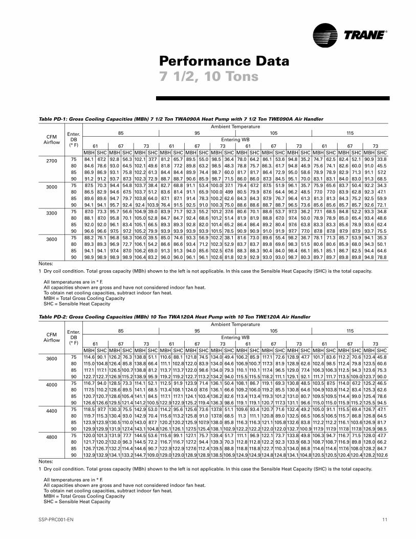
Table PD-1: Gross Cooling Capacities (MBh) 7 1/2 Ton TWA090A Heat Pump with 7 1/2 Ton TWE090A Air Handler
Notes:
1 Dry coil condition. Total gross capacity (MBh) shown to the left is not applicable. In this case the Sensible Heat Capacity (SHC) is the total capacity.
All temperatures are in ° F.All capacities shown are gross and have not considered indoor fan heat.To obtain net cooling capacities, subtract indoor fan heat.MBH = Total Gross Cooling CapacitySHC = Sensible Heat Capacity
Table PD-2: Gross Cooling Capacities (MBh) 10 Ton TWA120A Heat Pump with 10 Ton TWE120A Air Handler
Notes:
1 Dry coil condition. Total gross capacity (MBh) shown to the left is not applicable. In this case the Sensible Heat Capacity (SHC) is the total capacity.
All temperatures are in ° F.All capacities shown are gross and have not considered indoor fan heat.To obtain net cooling capacities, subtract indoor fan heat.MBH = Total Gross Cooling CapacitySHC = Sensible Heat Capacity
CFM Airflow
Enter. DB(° F)
Ambient Temperature85 95 105 115
Entering WB61 67 73 61 67 73 61 67 73 61 67 73
MBH SHC MBH SHC MBH SHC MBH SHC MBH SHC MBH SHC MBH SHC MBH SHC MBH SHC MBH SHC MBH SHC MBH SHC
2700 75 84.1 67.2 92.8 56.3 102.1 37.7 81.2 65.7 89.5 55.0 98.5 36.4 78.0 64.2 86.1 53.6 94.8 35.2 74.7 62.5 82.4 52.1 90.9 33.880 84.6 78.6 93.0 64.5 102.1 49.6 81.8 77.2 89.8 63.2 98.5 48.3 78.8 75.7 86.3. 61.7 94.8 46.9 75.6 74.1 82.6 60.0 91.0 45.585 86.9 86.9 93.1 75.8 102.2 61.3 84.4 84.4 89.9 74.4 98.7 60.0 81.7 81.7 86.4 72.9 95.0 58.6 78.9 78.9 82.9 71.3 91.1 57.290 91.2 91.2 93.7 87.3 102.3 72.9 88.7 88.7 90.6 85.9 98.7 71.5 86.0 86.0 87.3 84.5 95.1 70.0 83.1 83.1 84.0 83.0 91.3 68.5
3000 75 87.5 70.3 94.4 54.8 103.7 38.4 82.7 68.8 91.1 53.4 100.0 37.1 79.4 67.2 87.5 51.9 96.1 35.7 75.9 65.6 83.7 50.4 92.2 34.380 86.5 82.9 94.6 67.5 103.7 51.2 83.6 81.4 91.1 65.9 100.0 499 80.5 79.9 87.6 64.4 96.2 48.5 77.0 77.0 83.9 62.8 92.3 47.185 89.6 89.6 94.7 79.7 103.8 64.0 87.1 87.1 91.4 78.3 100.2 62.6 84.3 84.3 87.9 76.7 96.4 61.3 81.3 81.3 84.3 75.2 92.5 59.990 94.1 94.1 95.7 92.4 92.4 103.9 76.4 91.5 92.5 91.0 100.3 75.0 88.6 88.6 88.7 88.7 96.5 73.6 85.6 85.6 85.7 85.7 92.6 72.1
3300 75 87.0 73.3 95.7 56.6 104.9 39.0 83.9 71.7 92.3 55.2 101.2 37.6 80.6 70.1 88.6 53.7 97.3 36.2 77.1 68.5 84.8 52.2 93.3 34.880 88.1 87.0 95.8 70.1 105.0 52.8 84.7 84.7 92.4 68.6 101.2 51.4 81.9 81.9 88.8 67.0 97.4 50.0 78.9 78.9 85.0 65.4 93.4 48.685 92.0 92.0 96.1 83.4 105.1 66.5 89.3 89.3 92.8 82.0 101.4 65.2 86.4 86.4 89.2 80.4 97.6 63.8 83.3 83.3 85.6 78.9 93.6 62.490 96.6 96.6 97.5 97.2 105.2 79.9 93.9 93.9 93.9 93.9 101.5 78.5 90.9 90.9 91.0 91.9 97.7 77.0 87.8 87.8 87.9 87.9 93.7 75.5
3600 75 88.2 76.1 96.8 58.3 106.0 39.5 85.0 74.6 93.3 56.9 102.2 38.1 81.6 73.0 89.6 55.4 98.2 36.7 78.1 71.3 85.7 53.9 94.1 35.380 89.3 89.3 96.9 72.7 106.1 54.2 86.6 86.6 93.4 71.2 102.3 52.9 83.7 83.7 89.8 69.6 98.3 51.5 80.6 80.6 85.9 68.0 94.3 50.185 94.1 94.1 97.4 87.0 106.2 69.0 91.3 91.3 94.0 85.6 102.5 67.6 88.3 88.3 90.4 84.0 98.4 66.1 85.1 85.1 86.7 82.5 94.4 64.690 98.9 98.9 98.9 98.9 106.4 83.2 96.0 96.0 96.1 96.1 102.6 81.8 92.9 92.9 93.0 93.0 98.7 80.3 89.7 89.7 89.8 89.8 94.8 78.8
CFM Airflow
Enter. DB(° F)
Ambient Temperature85 95 105 115
Entering WB61 67 73 61 67 73 61 67 73 61 67 73
MBH SHC MBH SHC MBH SHC MBH SHC MBH SHC MBH SHC MBH SHC MBH SHC MBH SHC MBH SHC MBH SHC MBH SHC
3600 75 114.6 90.1 126.2 76.3 138.8 51.1 110.6 88.1 121.8 74.5 134.0 49.4 106.2 85.9 117.1 72.6 128.9 47.7 101.7 83.6 112.2 70.6 123.4 45.880 115.0 104.8 126.4 85.8 138.8 66.4 111.1 102.8 122.0 83.9 134.0 64.6 106.9 100.7 117.3 81.9 128.9 62.6 102.6 98.5 112.4 79.8 123.5 60.685 117.1 117.1 126.5 100.7 138.8 81.2 113.7 113.7 122.0 98.6 134.0 79.3 110.1 110.1 117.4 96.5 129.0 77.4 106.3 106.3 112.5 94.3 123.6 75.390 122.7 122.7 126.9 115.2 138.9 95.9 119.2 119.2 122.7 113.2 134.2 94.0 115.5 115.5 118.2 111.1 129.1 92.1 111.7 111.7 113.5 109.0 123.7 90.0
4000 75 116.7 94.0 128.5 73.3 114.1 52.1 112.5 91.9 123.9 71.4 136.1 50.4 108.1 86.7 119.1 69.3 130.8 48.5 103.5 87.5 114.0 67.2 125.2 46.580 117.5 110.2 128.6 89.5 141.1 68.5 113.4 108.1 124.0 87.6 136.1 66.6 109.2 106.0 119.2 85.5 130.8 64.6 104.9 103.8 114.2 83.4 125.3 62.685 120.7 120.7 128.6 105.4 141.1 84.5 117.1 117.1 124.1 103.4 136.2 82.6 113.4 113.4 119.3 101.2 131.0 80.7 109.5 109.5 114.4 99.0 125.4 78.690 126.6 126.6 129.5 121.4 141.2 100.5 122.9 122.9 125.2 119.4 136.3 98.6 119.1 119.1 120.7 117.3 131.1 96.6 115.0 115.0 115.9 115.2 125.5 94.5
4400 75 118.5 97.7 130.3 75.5 142.9 53.0 114.2 95.6 125.6 73.6 137.8 51.1 109.6 93.4 120.7 71.6 132.4 49.2 105.0 91.1 115.5 69.4 126.7 47.180 119.7 115.3 130.4 93.0 142.9 70.4 115.6 113.2 125.8 91.0 137.8 68.5 11.3 111.1 120.8 89.0 132.5 66.5 106.5 106.5 115.7 86.8 126.8 64.585 123.9 123.9 130.5 110.0 143.0 87.7 120.2 120.2 125.9 107.9 138.0 85.8 116.3 116.3 121.1 105.8 132.6 83.8 112.2 112.2 116.1 103.6 126.9 81.790 129.9 129.9 131.9 127.4 143.1 104.8 126.1 126.1 127.5 125.4 138.1 102.9 122.2 122.2 122.0 122.0 132.7 100.9 117.9 117.9 117.8 117.8 126.9 98.5
4800 75 120.0 101.3 131.9 77.7 144.5 53.6 115.6 99.1 127.1 75.7 139.4 51.7 111.1 96.9 122.1 73.7 133.8 49.8 106.3 94.7 116.7 71.5 128.0 47.780 121.7 120.2 132.0 96.3 144.5 72.2 116.7 116.7 127.2 94.4 139.3 70.3 112.8 112.8 122.2 92.3 133.9 68.3 108.7 108.7 116.9 89.8 128.0 66.285 126.7 126.7 132.2 114.4 144.6 90.7 122.9 122.9 127.6 112.4 139.5 88.8 118.8 118.8 122.7 110.3 134.0 86.8 114.6 114.6 117.6 108.0 128.2 84.790 132.9 132.9 134.1 133.2 144.7 109.0 129.0 129.0 128.9 128.9 138.5 106.9 124.9 124.9 124.8 124.8 134.1 104.8 120.5 120.5 120.4 120.4 128.2 102.6
Performance Data7 1/2, 10 Tons
12 SSP-PRC001-EN
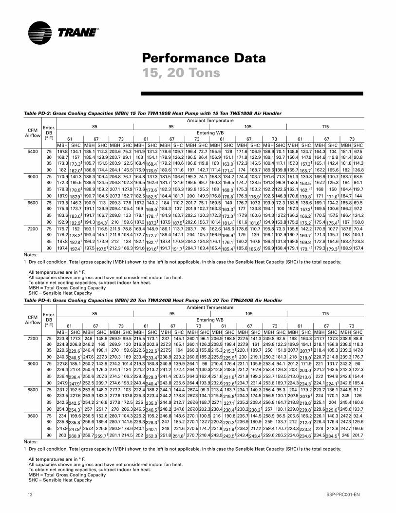
Table PD-3: Gross Cooling Capacities (MBh) 15 Ton TWA180B Heat Pump with 15 Ton TWE180B Air Handler
Notes:
1 Dry coil condition. Total gross capacity (MBh) shown to the left is not applicable. In this case the Sensible Heat Capacity (SHC) is the total capacity.
All temperatures are in ° F.All capacities shown are gross and have not considered indoor fan heat.To obtain net cooling capacities, subtract indoor fan heat.MBH = Total Gross Cooling CapacitySHC = Sensible Heat Capacity
Table PD-4: Gross Cooling Capacities (MBh) 20 Ton TWA240B Heat Pump with 20 Ton TWE240B Air Handler
Notes:
1 Dry coil condition. Total gross capacity (MBh) shown to the left is not applicable. In this case the Sensible Heat Capacity (SHC) is the total capacity.
All temperatures are in ° F.All capacities shown are gross and have not considered indoor fan heat.To obtain net cooling capacities, subtract indoor fan heat.MBH = Total Gross Cooling CapacitySHC = Sensible Heat Capacity
CFM Airflow
Enter. DB(° F)
Ambient Temperature85 95 105 115
Entering WB61 67 73 61 67 73 61 67 73 61 67 73
MBH SHC MBH SHC MBH SHC MBH SHC MBH SHC MBH SHC MBH SHC MBH SHC MBH SHC MBH SHC MBH SHC MBH SHC5400 75 167.8 134.1 185.1 112.3 203.6 75.2 161.9 131.2 178.6 109.7 196.4 72.7 155.5 128 171.6 106.9 188.9 70.1 148.8 124.7 164.3 104 181.1 67.5
80 168.7 157 185.4 128.9 203.7 99.1 163 154.1 178.9 126.2 196.5 96.4 156.9 151.1 171.8 122.9 189.1 93.7 150.4 147.9 164.6 119.8 181.4 90.885 173.3 173.31 185.7 151.5 203.9 122.5 168.4 168.41 179.2 148.6 196.8 119.8 163 163.01 172.3 145.5 189.4 117.1 157.3 157.31 165.1 142.4 181.8 114.3
90 182 182.01 186.8 174.4 204.1 145.5 176.9 176.91 180.6 171.6 197 142.7 171.4 171.41 174 168.7 189.6 139.8 165.7 165.71 167.2 165.6 182 136.8
6000 75 170.9 140.3 188.3 109.4 206.8 76.7 164.8 137.3 181.5 106.6 199.3 74.1 158.3 134.2 174.4 103.7 191.6 71.3 151.3 130.8 166.9 100.7 183.7 68.580 172.3 165.5 188.4 134.5 206.8 102.3 166.5 162.6 181.7 131.6 199.5 99.7 160.3 159.5 174.7 128.5 191.8 96.9 153.5 153.51 167.2 125.3 184 94.1
85 178.8 178.81 188.9 159.2 207.1 127.9 173.6 173.61 182.3 156.3 199.8 125.2 168 168.01 175.3 153.2 192.2 122.5 162.1 162.11 168 150 184.4 119.7
90 187.9 187.91 190.7 184.5 207.3 152.7 182.5 182.51 184.4 181.7 200 149.9 176.8 176.81 176.9 176.91 192.5 146.9 170.8 170.81 171 171.01 184.7 144
6600 75 173.5 146.3 190.9 113 209.3 77.8 167.2 143.2 184 110.2 201.7 75.1 160.5 140 176.7 107.3 193.9 72.3 153.5 136.6 169.1 104.2 185.8 69.580 175.6 173.7 191.1 139.9 209.4 105.4 169 169.01 184.3 137 201.9 102.7 163.3 163.31 177 133.8 194.1 100 157.3 157.31 169.5 130.6 186.2 97.2
85 183.6 183.61 191.7 166.7 209.8 133 178.1 178.11 184.9 163.7 202.3 130.3 172.3 172.31 177.9 160.6 194.3 127.2 166.2 166.21 170.5 157.5 186.4 124.2
90 192.9 192.91 194.3 194.31 210 159.6 187.3 187.31 187.5 187.51 202.6 156.7 181.4 181.41 181.6 181.61 194.9 153.8 175.2 175.21 175.4 175.41 187 150.8
7200 75 175.7 152 193.1 116.5 211.5 78.8 169.4 148.9 186.1 113.7 203.7 76 162.6 145.6 178.6 110.7 195.8 73.3 155.5 142.2 170.9 107.7 187.6 70.480 178.2 178.21 193.4 145.1 211.6 108.4 172.7 172.71 186.4 142.1 204 105.7 166.9 166.91 179 139 196.1 102.9 160.7 160.71 171.3 135.7 188 100.185 187.8 187.81 194.2 173.9 212 138 182.1 182.11 187.4 170.9 204.2 134.8 176.1 176.11 180.2 167.8 196.4 131.8 169.8 169.81 172.8 164.6 188.4 128.8
90 197.4 197.41 197.5 197.51 212.3 166.3 191.6 191.61 191.7 191.71 204.7 163.4 185.4 185.41 185.6 185.61 196.9 160.4 179.1 179.11 179.3 179.31 188.9 157.4
CFM Airflow
Enter. DB(° F)
Ambient Temperature85 95 105 115
Entering WB61 67 73 61 67 73 61 67 73 61 67 73
MBH SHC MBH SHC MBH SHC MBH SHC MBH SHC MBH SHC MBH SHC MBH SHC MBH SHC MBH SHC MBH SHC MBH SHC7200 75 223.8 177.3 246 148.8 269.9 99.5 215.5 173.1 237 145.1 260.1 96.1 206.9 168.8 227.5 141.3 249.8 92.5 198 164.3 217.7 137.3 238.9 88.8
80 224.8 206.8 246.2 169 269.9 130 216.8 202.6 237.3 165.1 260.1 126.2 208.5 198.4 227.9 161 249.8 122.3 199.9 194.1 218.1 156.9 238.9 118.385 229.6 229.61 246.4 198.1 270 159.6 222.6 222.61 237.5 194 260.3 155.8 215.3 215.31 228.1 189.7 250 151.9 207.7 207.71 218.4 185.3 239.2 147.8
90 240.5 240.51 247.6 227.3 270.3 189 233.4 233.41 238.9 223.2 260.6 185.2 225.9 225.91 230 219.1 250.3 181.3 218 218.01 220.7 214.8 239.3 176.7
8000 75 227.8 185.1 250.2 143.9 274.2 101.4 219.3 180.8 240.9 139.9 264.1 98 210.4 176.4 231.1 135.9 253.4 94.1 201.2 171.9 221 131.7 242.2 9080 229.4 217.4 250.4 176.3 274.1 134 221.2 213.2 241.2 172.4 264.1 130.3 212.8 208.9 231.2 167.9 253.4 126.3 203 203.01 221.2 163.5 242.3 122.3
85 236.4 236.41 250.6 207.6 274.3 166.2 229.3 229.31 241.4 203.5 264.3 162.4 221.6 221.61 231.9 199.2 253.7 158.5 213.6 213.61 222 194.8 242.6 154.490 247.9 247.91 252.5 239.7 274.6 198.2 240.4 240.41 243.8 235.6 264.4 193.9 232.6 232.61 234.7 231.4 253.8 189.7 224.3 224.31 224.1 224.11 242.8 185.4
8800 75 231.2 192.5 253.6 148.3 277.7 103 222.4 188.2 244.1 144.4 267.4 99.3 213.4 183.7 234.1 140.3 256.4 95.3 204 179.2 223.7 136.1 244.9 91.280 233.5 227.6 253.9 183.3 277.6 137.8 225.3 223.4 244.2 178.8 267.3 134.1 215.8 215.81 234.3 174.5 256.5 130.1 207.8 207.81 224 170.1 245 126
85 242.5 242.51 254.2 216.8 277.9 172.5 235 235.01 244.9 212.7 267.6 168.7 227.1 227.11 235.2 208.4 256.8 164.7 218.8 218.81 225.1 204 245.4 160.6
90 254.3 254.31 257 251.7 278 206.3 246.5 246.51 248.2 247.6 267.8 202.3 238.4 238.41 238.2 238.21 257 198.1 229.8 229.81 229.6 229.61 245.6 193.7
9600 75 234 199.6 256.5 152.6 280.7 104.3 225.2 195.2 246.8 148.6 270.1 100.5 216 190.8 236.7 144.5 258.9 96.5 206.6 186.2 226.1 140.3 247.2 92.480 235.8 235.81 256.6 189.4 280.7 141.5 228.3 228.31 247 185.2 270.1 137.7 220.3 220.31 236.9 180.9 259 133.7 212 212.01 226.4 176.4 247.3 129.6
85 247.9 247.91 257.4 225.8 280.9 178.6 240.1 240.11 248 221.6 270.5 174.7 231.9 231.91 238.2 217.2 259.4 170.7 223.3 223.31 228 212.8 247.7 166.6
90 260 260.01 259.7 259.71 281.1 214.5 252 252.01 251.8 251.81 270.7 210.4 243.5 243.51 243.4 243.41 259.6 206.2 234.6 234.61 234.5 234.51 248 201.7
Performance Data15, 20 Tons
SSP-PRC001-EN 13
.
OutdoorTemperatureIn Degrees F
Suction Temperature Degrees F
30 35 40 45 50 5565 Head press PSIG 168 173 179 185 191 197
Cap. Btuh/1000 81 89 97.2 105.8 114.5 123.4Unit KW 5.56 5.69 5.83 5.97 6.13 6.28
75 Head press PSIG 194 199 205 211 217 224Cap. Btuh/1000 77.8 85.3 93.1 101.1 109.4 117.8Unit KW 6.09 6.23 6.38 6.54 6.7 6.87
85 Head press PSIG 221 227 234 240 247 254Cap. Btuh/1000 74.1 81.3 88.7 96.3 104.2 112.3Unit KW 6.71 6.87 7.03 7.2 7.38 7.56
95 Head press PSIG 252 258 265 272 279 286Cap. Btuh/1000 70.3 77.1 84.1 91.4 98.9 106.7Unit KW 7.43 7.6 7.77 7.95 8.14 8.33
105 Head press PSIG 285 292 299 306 314 322Cap. Btuh/1000 66.1 72.6 79.3 86.3 93.5 101.1Unit KW 8.23 8.41 8.6 8.79 8.98 9.18
115 Head press PSIG 321 328 336 343 351 360Cap. Btuh/1000 61.8 67.9 74.3 81 88.1 95.5Unit KW 9.12 9.32 9.51 9.71 9.91 10.12
Performance Data7 1/2 Ton
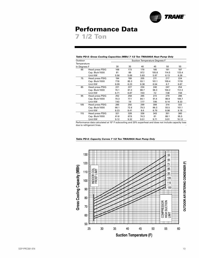
Table PD-5: Gross Cooling Capacities (MBh) 7 1/2 Ton TWA090A Heat Pump Only
Performance data calculated at 15° F subcooling and 20% superheat and does not include capacity lossdue to refrigerant lines.
Table PD-6: Capacity Curves 7 1/2 Ton TWA090A Heat Pump Only
14 SSP-PRC001-EN
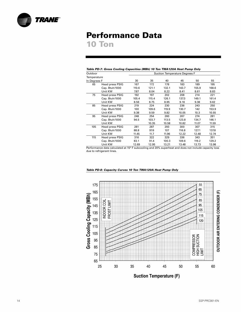
Table PD-7: Gross Cooling Capacities (MBh) 10 Ton TWA120A Heat Pump Only
Performance data calculated at 15° F subcooling and 20% superheat and does not include capacity loss due to refrigerant lines.
Table PD-8: Capacity Curves 10 Ton TWA120A Heat Pump Only
OutdoorTemperatureIn Degrees F
Suction Temperature Degrees F
30 35 40 45 50 5565 Head press PSIG 167 172 178 183 189 195
Cap. Btuh/1000 110.6 121.1 132.1 143.7 155.9 168.6Unit KW 7.87 8.04 8.22 8.41 8.61 8.83
75 Head press PSIG 192 197 202 208 214 221Cap. Btuh/1000 105.4 115.4 126.1 137.3 149.1 161.4Unit KW 8.56 8.75 8.95 9.16 9.38 9.62
85 Head press PSIG 219 224 230 236 243 250Cap. Btuh/1000 100 109.6 119.9 130.7 142 153.9Unit KW 9.38 9.59 9.82 10.05 10.3 10.55
95 Head press PSIG 248 254 260 267 274 281Cap. Btuh/1000 94.5 103.7 113.5 123.8 134.7 146.1Unit KW 10.35 10.58 10.82 11.07 11.59
105 Head press PSIG 281 287 293 300 307 315Cap. Btuh/1000 88.8 97.6 107 116.8 127.1 137.8Unit KW 11.45 11.7 11.96 12.22 12.48 12.74
115 Head press PSIG 316 322 329 336 343 351Cap. Btuh/1000 83.1 91.4 100.3 109.6 119.2 129.2Unit KW 12.69 12.95 13.21 13.48 13.73 13.98
Performance Data10 Ton

SSP-PRC001-EN 15
Table PD-9: Gross Cooling Capacities (MBh) 15 Ton TWA180B Heat Pump Only
Performance data calculated at 15° F subcooling and 20% superheat and does not include capacity loss due to refrigerant lines.
Table PD-10: Capacity Curves 15 Ton TWA180B Heat Pump Only
OutdoorTemperatureIn Degrees F
Suction Temperature Degrees F
30 35 40 45 50 5565 Head pressure PSIG 168 173 179 185 191 197
Capacity BTUH/1000 161.3 177.1 193.6 210.6 228.1 245.8Unit KW 10.9 11.16 11.43 11.71 12.01 12.32
75 Head pressure PSIG 193 199 205 211 217 224Capacity BTUH/1000 154.9 169.9 185.5 201.5 218 234.8Unit KW 11.94 12.22 12.51 12.82 13.14 13.47
85 Head pressure PSIG 221 227 233 240 247 254Capacity BTUH/1000 147.7 162 176.8 192.1 207.8 224Unit KW 13.16 13.46 13.78 14.11 14.46 14.81
95 Head pressure PSIG 252 258 265 272 279 286Capacity BTUH/1000 140.1 153.7 167.8 182.4 197.5 213.1Unit KW 14.56 14.89 15.23 15.59 15.95 16.32
105 Head pressure PSIG 285 292 299 306 313 321Capacity BTUH/1000 131.9 144.8 158.2 172.2 186.8 202.1Unit KW 16.14 16.49 16.85 17.23 17.61 18
115 Head pressure PSIG 321 328 335 343 351 360Capacity BTUH/1000 123.3 135.5 148.3 161.8 176 190.9Unit KW 17.88 18.25 18.64 19.03 19.43 19.83
Performance Data15 Ton
Ou
tdo
or
Air
En
teri
ng
Co
nd
ense
r (F
)
16 SSP-PRC001-EN
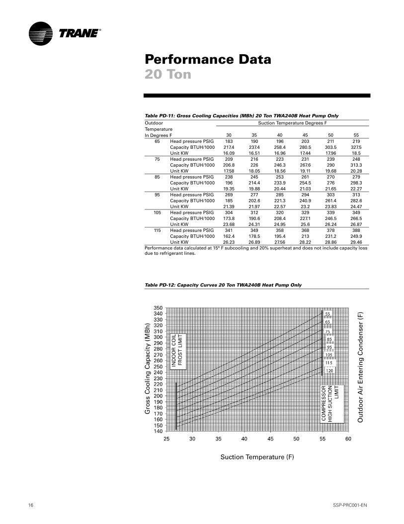
Table PD-11: Gross Cooling Capacities (MBh) 20 Ton TWA240B Heat Pump Only
Performance data calculated at 15° F subcooling and 20% superheat and does not include capacity loss due to refrigerant lines.
Table PD-12: Capacity Curves 20 Ton TWA240B Heat Pump Only
OutdoorTemperatureIn Degrees F
Suction Temperature Degrees F
30 35 40 45 50 5565 Head pressure PSIG 183 190 196 203 211 219
Capacity BTUH/1000 217.4 237.4 258.4 280.5 303.5 327.5Unit KW 16.09 16.51 16.96 17.44 17.96 18.5
75 Head pressure PSIG 209 216 223 231 239 248Capacity BTUH/1000 206.8 226 246.3 267.6 290 313.3Unit KW 17.58 18.05 18.56 19.11 19.68 20.28
85 Head pressure PSIG 238 245 253 261 270 279Capacity BTUH/1000 196 214.4 233.9 254.5 276 298.3Unit KW 19.35 19.88 20.44 21.03 21.65 22.27
95 Head pressure PSIG 269 277 285 294 303 313Capacity BTUH/1000 185 202.6 221.3 240.9 261.4 282.6Unit KW 21.39 21.97 22.57 23.2 23.83 24.47
105 Head pressure PSIG 304 312 320 329 339 349Capacity BTUH/1000 173.8 190.6 208.4 227.1 246.5 266.5Unit KW 23.68 24.31 24.95 25.6 26.24 26.87
115 Head pressure PSIG 341 349 358 368 378 388Capacity BTUH/1000 162.4 178.5 195.4 213 231.2 249.9Unit KW 26.23 26.89 27.56 28.22 28.86 29.46
Performance Data20 Ton
Ou
tdo
or
Air
En
teri
ng
Co
nd
ense
r (F
)
SSP-PRC001-EN 17
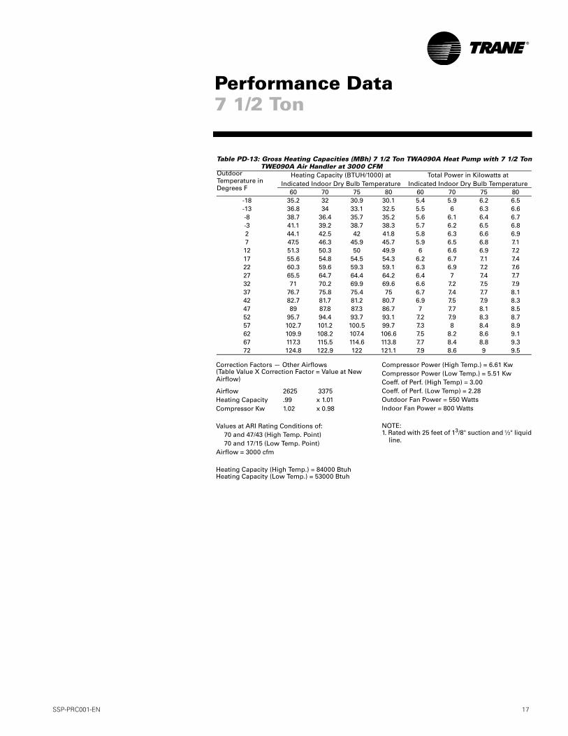
Table PD-13: Gross Heating Capacities (MBh) 7 1/2 Ton TWA090A Heat Pump with 7 1/2 TonTWE090A Air Handler at 3000 CFM
Outdoor Temperature in Degrees F
Heating Capacity (BTUH/1000) atIndicated Indoor Dry Bulb Temperature
Total Power in Kilowatts atIndicated Indoor Dry Bulb Temperature
60 70 75 80 60 70 75 80-18 35.2 32 30.9 30.1 5.4 5.9 6.2 6.5-13 36.8 34 33.1 32.5 5.5 6 6.3 6.6-8 38.7 36.4 35.7 35.2 5.6 6.1 6.4 6.7-3 41.1 39.2 38.7 38.3 5.7 6.2 6.5 6.82 44.1 42.5 42 41.8 5.8 6.3 6.6 6.97 47.5 46.3 45.9 45.7 5.9 6.5 6.8 7.112 51.3 50.3 50 49.9 6 6.6 6.9 7.217 55.6 54.8 54.5 54.3 6.2 6.7 7.1 7.422 60.3 59.6 59.3 59.1 6.3 6.9 7.2 7.627 65.5 64.7 64.4 64.2 6.4 7 7.4 7.732 71 70.2 69.9 69.6 6.6 7.2 7.5 7.937 76.7 75.8 75.4 75 6.7 7.4 7.7 8.142 82.7 81.7 81.2 80.7 6.9 7.5 7.9 8.347 89 87.8 87.3 86.7 7 7.7 8.1 8.552 95.7 94.4 93.7 93.1 7.2 7.9 8.3 8.757 102.7 101.2 100.5 99.7 7.3 8 8.4 8.962 109.9 108.2 107.4 106.6 7.5 8.2 8.6 9.167 117.3 115.5 114.6 113.8 7.7 8.4 8.8 9.372 124.8 122.9 122 121.1 7.9 8.6 9 9.5
Performance Data7 1/2 Ton
Correction Factors — Other Airflows(Table Value X Correction Factor = Value at New Airflow)
Airflow 2625 3375Heating Capacity .99 x 1.01Compressor Kw 1.02 x 0.98
Values at ARI Rating Conditions of:70 and 47/43 (High Temp. Point)70 and 17/15 (Low Temp. Point)
Airflow = 3000 cfm
Heating Capacity (High Temp.) = 84000 BtuhHeating Capacity (Low Temp.) = 53000 Btuh
Compressor Power (High Temp.) = 6.61 KwCompressor Power (Low Temp.) = 5.51 KwCoeff. of Perf. (High Temp) = 3.00Coeff. of Perf. (Low Temp) = 2.28Outdoor Fan Power = 550 WattsIndoor Fan Power = 800 Watts
NOTE:1. Rated with 25 feet of 13/8" suction and ½" liquid
line.
18 SSP-PRC001-EN
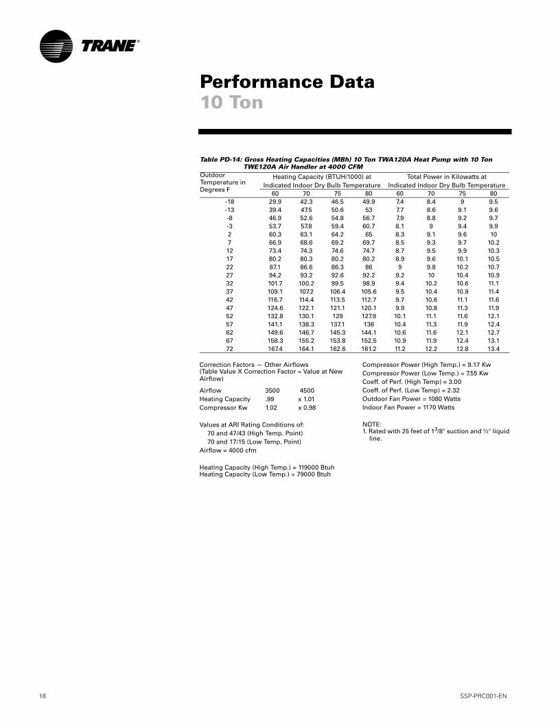
Table PD-14: Gross Heating Capacities (MBh) 10 Ton TWA120A Heat Pump with 10 Ton TWE120A Air Handler at 4000 CFM
Outdoor Temperature in Degrees F
Heating Capacity (BTUH/1000) atIndicated Indoor Dry Bulb Temperature
Total Power in Kilowatts atIndicated Indoor Dry Bulb Temperature
60 70 75 80 60 70 75 80-18 29.9 42.3 46.5 49.9 7.4 8.4 9 9.5-13 39.4 47.5 50.6 53 7.7 8.6 9.1 9.6-8 46.9 52.6 54.8 56.7 7.9 8.8 9.2 9.7-3 53.7 57.8 59.4 60.7 8.1 9 9.4 9.92 60.3 63.1 64.2 65 8.3 9.1 9.6 107 66.9 68.6 69.2 69.7 8.5 9.3 9.7 10.212 73.4 74.3 74.6 74.7 8.7 9.5 9.9 10.317 80.2 80.3 80.2 80.2 8.9 9.6 10.1 10.522 87.1 86.6 86.3 86 9 9.8 10.2 10.727 94.2 93.2 92.6 92.2 9.2 10 10.4 10.932 101.7 100.2 99.5 98.9 9.4 10.2 10.6 11.137 109.1 107.2 106.4 105.6 9.5 10.4 10.9 11.442 116.7 114.4 113.5 112.7 9.7 10.6 11.1 11.647 124.6 122.1 121.1 120.1 9.9 10.8 11.3 11.952 132.8 130.1 129 127.9 10.1 11.1 11.6 12.157 141.1 138.3 137.1 136 10.4 11.3 11.9 12.462 149.6 146.7 145.3 144.1 10.6 11.6 12.1 12.767 158.3 155.2 153.8 152.5 10.9 11.9 12.4 13.172 167.4 164.1 162.6 161.2 11.2 12.2 12.8 13.4
Performance Data10 Ton
Correction Factors — Other Airflows(Table Value X Correction Factor = Value at New Airflow)
Airflow 3500 4500Heating Capacity .99 x 1.01Compressor Kw 1.02 x 0.98
Values at ARI Rating Conditions of:70 and 47/43 (High Temp. Point)70 and 17/15 (Low Temp. Point)
Airflow = 4000 cfm
Heating Capacity (High Temp.) = 119000 BtuhHeating Capacity (Low Temp.) = 79000 Btuh
Compressor Power (High Temp.) = 9.17 KwCompressor Power (Low Temp.) = 7.55 KwCoeff. of Perf. (High Temp) = 3.00Coeff. of Perf. (Low Temp) = 2.32Outdoor Fan Power = 1080 WattsIndoor Fan Power = 1170 Watts
NOTE:1. Rated with 25 feet of 13/8" suction and ½" liquid
line.
SSP-PRC001-EN 19
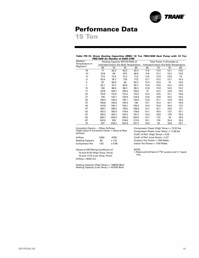
Table PD-15: Gross Heating Capacities (MBh) 15 Ton TWA180B Heat Pump with 15 TonTWE180B Air Handler at 6000 CFM
Outdoor Temperature in Degrees F
Heating Capacity (BTUH/1000) atIndicated Indoor Dry Bulb Temperature
Total Power in Kilowatts atIndicated Indoor Dry Bulb Temperature
60 70 75 80 60 70 75 8018 71 65.3 63.5 62.2 11.6 12.6 13.1 13.5-13 73.8 69 67.5 66.5 11.8 12.7 13.2 13.8-8 77.4 73.4 72.2 71.5 11.9 12.9 13.5 14-3 81.8 78.7 77.8 77.3 12.1 13.2 13.7 14.32 87 84.6 84 83.7 12.3 13.4 14 14.67 93.1 91.2 90.8 90.7 12.6 13.6 14.2 14.912 100 98.6 98.3 98.3 12.8 13.9 14.5 15.217 107.8 106.7 106.4 106.5 13 14.2 14.8 15.522 116.5 115.5 115.3 115.3 13.3 14.5 15.1 15.827 126 125.1 124.9 124.8 13.6 14.8 15.5 16.232 136.3 135.4 135.1 134.9 13.9 15.1 15.8 16.637 146.8 145.8 145.4 145 14.1 15.4 16.1 16.942 157.9 156.7 156.1 155.6 14.4 15.8 16.5 17.347 169.7 168.2 167.5 166.8 14.7 16.1 16.9 17.752 182.2 180.4 179.6 178.8 15.1 16.5 17.2 18.157 195.2 193.2 192.2 191.2 15.4 16.8 17.6 18.562 208.7 206.4 205.3 204.2 15.7 17.2 18 18.967 222.6 220 218.8 217.6 16.1 17.6 18.4 19.372 237 234.2 232.9 231.7 16.5 18 18.8 19.7
Performance Data15 Ton
Correction Factors — Other Airflows(Table Value X Correction Factor = Value at New Airflow)
Airflow 5250 6750Heating Capacity .99 x 1.01Compressor Kw 1.02 x 0.98
Values at ARI Rating Conditions of:70 and 47/43 (High Temp. Point)70 and 17/15 (Low Temp. Point)
Airflow = 6000 cfm
Heating Capacity (High Temp.) = 168000 BtuhHeating Capacity (Low Temp.) = 107000 Btuh
Compressor Power (High Temp.) = 13.32 KwCompressor Power (Low Temp.) = 11.06 KwCoeff. of Perf. (High Temp) = 3.00Coeff. of Perf. (Low Temp) = 2.27Outdoor Fan Power = 1100 WattsIndoor Fan Power = 1700 Watts
NOTE:1. Rated with 25 feet of 13/8" suction and ½" liquid
line.
20 SSP-PRC001-EN
Performance Data20 Ton
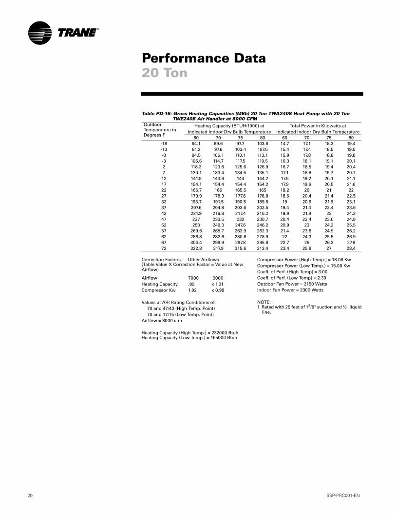
Table PD-16: Gross Heating Capacities (MBh) 20 Ton TWA240B Heat Pump with 20 Ton TWE240B Air Handler at 8000 CFM
Outdoor Temperature in Degrees F
Heating Capacity (BTUH/1000) atIndicated Indoor Dry Bulb Temperature
Total Power in Kilowatts atIndicated Indoor Dry Bulb Temperature
60 70 75 80 60 70 75 80-18 64.1 89.6 97.7 103.6 14.7 17.1 18.3 19.4-13 81.2 97.6 103.4 107.6 15.4 17.4 18.5 19.5-8 94.5 106.1 110.1 113.1 15.9 17.8 18.8 19.8-3 106.6 114.7 117.5 119.5 16.3 18.1 19.1 20.12 118.3 123.8 125.6 126.9 16.7 18.5 19.4 20.47 130.1 133.4 134.5 135.1 17.1 18.8 19.7 20.712 141.9 143.6 144 144.2 17.5 19.2 20.1 21.117 154.1 154.4 154.4 154.2 17.9 19.6 20.5 21.622 166.7 166 165.5 165 18.2 20 21 2227 179.9 178.3 177.6 176.8 18.6 20.4 21.4 22.532 193.7 191.5 190.5 189.5 19 20.9 21.9 23.137 207.6 204.8 203.6 202.5 19.4 21.4 22.4 23.642 221.9 218.8 217.4 216.2 19.9 21.9 23 24.247 237 233.5 232 230.7 20.4 22.4 23.6 24.852 253 249.3 247.6 246.2 20.9 23 24.2 25.557 269.6 265.7 263.9 262.3 21.4 23.6 24.9 26.262 286.8 282.6 280.6 278.9 22 24.3 25.5 26.967 304.4 299.9 297.8 295.8 22.7 25 26.3 27.672 322.8 317.9 315.6 313.4 23.4 25.8 27 28.4
Correction Factors — Other Airflows(Table Value X Correction Factor = Value at New Airflow)
Airflow 7000 9000Heating Capacity .99 x 1.01Compressor Kw 1.02 x 0.98
Values at ARI Rating Conditions of:70 and 47/43 (High Temp. Point)70 and 17/15 (Low Temp. Point)
Airflow = 8000 cfm
Heating Capacity (High Temp.) = 232000 BtuhHeating Capacity (Low Temp.) = 155000 Btuh
Compressor Power (High Temp.) = 18.08 KwCompressor Power (Low Temp.) = 15.00 KwCoeff. of Perf. (High Temp) = 3.00Coeff. of Perf. (Low Temp) = 2.30Outdoor Fan Power = 2150 WattsIndoor Fan Power = 2300 Watts
NOTE:1. Rated with 25 feet of 13/8" suction and ½" liquid
line.
SSP-PRC001-EN 21
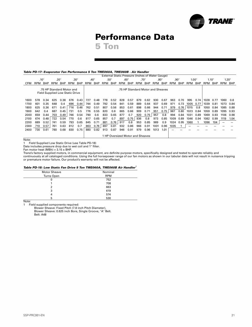
Table PD-17: Evaporator Fan Performance 5 Ton TWE060A, TWE060B - Air Handler
Note:1 Field Supplied Low Static Drive (use Table PD-18)Data includes pressure drop due to wet coil and 1" filter.Fan motor heat (MBh) = 3.15 x BHP.Trane’s factory supplied motors, in commercial equipment, are definite purpose motors, specifically designed and tested to operate reliably and continuously at all cataloged conditions. Using the full horsepower range of our fan motors as shown in our tabular data will not result in nuisance tripping or premature motor failure. Our product’s warranty will not be affected.
Table PD-18: Low Static Fan Drive 5 Ton TWE060A, TWE060B Air Handler1
Note:1 Field supplied components required:
Blower Sheave: Fixed Pitch (7.8 inch Pitch Diameter),Blower Sheave: 0.625 inch Bore, Single Groove, "A" Belt.Belt: A48
External Static Pressure (Inches of Water Gauge).10" .20" .30" .40" .50" .60" .70" .80" .90" 1.00" 1.10" 1.20"
CFM RPM BHP RPM BHP RPM BHP RPM BHP RPM BHP RPM BHP RPM BHP RPM BHP RPM BHP RPM BHP RPM BHP RPM BHP
.75 HP Standard Motor andField Supplied Low Static Drive
.75 HP Standard Motor and Sheaves
1600 578 0.34 625 0.38 676 0.43 727 0.48 778 0.52 828 0.57 879 0.62 930 0.67 963 0.70 995 0.74 1028 0.77 1060 0.81700 601 0.35 648 0.4 696 0.44 744 0.49 792 0.54 841 0.59 889 0.64 937 0.69 971 0.73 1005 0.77 1039 0.81 1073 0.841800 625 0.36 671 0.41 716 0.46 762 0.51 807 0.56 853 0.61 898 0.66 944 0.71 979 0.76 1015 0.8 1050 0.84 1085 0.881900 642 0.4 687 0.45 731 0.5 776 0.55 820 0.6 865 0.66 909 0.71 951 0.75 987 0.80 1023 0.84 1059 0.89 1095 0.932000 659 0.44 703 0.49 746 0.54 790 0.6 833 0.65 877 0.7 920 0.75 957 0.8 994 0.84 1031 0.89 1069 0.93 1106 0.982100 674 0.48 722 0.54 770 0.6 817 0.65 857 0.7 897 0.75 936 0.8 973 0.85 1009 0.89 1046 0.94 1082 0.99 1119 1.042200 689 0.52 741 0.59 793 0.65 845 0.71 881 0.76 917 0.8 953 0.85 989 0.9 1024 0.95 1060 1 1096 104 — —2300 710 0.57 761 0.63 812 0.7 863 0.76 897 0.81 932 0.86 966 0.91 1001 0.96 1035 1 — — — — — —2400 730 0.61 780 0.68 830 0.75 880 0.82 913 0.87 946 0.91 979 0.96 1013 1.01 — — — — — — — —
1 HP Oversized Motor and Sheaves
Motor SheaveTurns Open
NominalRPM
0 7521 7082 6633 6194 5745 530
Performance Data5 Ton
22 SSP-PRC001-EN
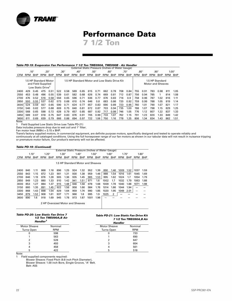
Table PD-19: Evaporator Fan Performance 7 1/2 Ton TWE090A, TWE090B - Air Handler
Note:1 Field Supplied Low Static Drive (use Table PD-21)Data includes pressure drop due to wet coil and 1" filter.Fan motor heat (MBh) = 3.15 x BHP.Trane’s factory supplied motors, in commercial equipment, are definite purpose motors, specifically designed and tested to operate reliably and continuously at all cataloged conditions. Using the full horsepower range of our fan motors as shown in our tabular data will not result in nuisance tripping or premature motor failure. Our product’s warranty will not be affected.
Table PD-19: (Continued)
Note:1 Field supplied components required:
Blower Sheave: Fixed Pitch (9.8 inch Pitch Diameter),Blower Sheave: 1.00 inch Bore, Single Groove, "A" Belt.Belt: A55
External Static Pressure (Inches of Water Gauge).10" .20" .30" .40" .50" .60" .70" .80" .90" 1.00"
CFM RPM BHP RPM BHP RPM BHP RPM BHP RPM BHP RPM BHP RPM BHP RPM BHP RPM BHP RPM BHP
1.5 HP Standard Motorand Field SuppliedLow Static Drive1
1.5 HP Standard Motor and Low Static Drive Kit 1.5 HP Standard Motor and Sheaves
2400 429 0.45 475 0.51 522 0.58 569 0.65 615 0.71 662 0.78 708 0.84 755 0.91 783 0.98 811 1.052550 453 0.48 496 0.55 539 0.61 582 0.68 626 0.74 669 0.81 712 0.87 756 0.94 785 1 814 1.082700 476 0.52 516 0.58 556 0.65 596 0.71 636 0.77 676 0.83 716 0.9 758 0.96 787 1.02 816 1.112850 500 0.55 537 0.62 573 0.68 610 0.74 646 0.8 683 0.86 720 0.92 759 0.99 788 1.05 819 1.143000 524 0.59 557 0.65 590 0.71 624 0.77 657 0.83 690 0.89 723 0.95 760 1.01 790 1.07 821 1.173150 546 0.62 577 0.68 609 0.75 640 0.81 672 0.87 703 0.94 735 1.00 768 1.07 798 1.15 829 1.253300 568 0.65 598 0.72 628 0.79 657 0.85 687 0.92 717 0.99 746 1.05 776 1.12 807 1.22 837 1.333450 589 0.67 618 0.75 647 0.83 676 0.91 705 0.99 733 1.07 762 1.15 791 1.23 820 1.33 849 1.423600 611 0.69 639 0.79 666 0.88 694 0.97 722 1.06 750 1.16 778 1.25 806 1.34 834 1.43 862 1.51
External Static Pressure (Inches of Water Gauge)1.10" 1.20" 1.30" 1.40" 1.50" 1.60" 1.70" 1.80"
CFM RPM BHP RPM BHP RPM BHP RPM BHP RPM BHP RPM BHP RPM BHP RPM BHP
1.5 HP Standard Motor and Sheaves
2400 840 1.11 868 1.18 896 1.25 924 1.32 952 1.39 890 1.46 1009 1.52 1037 1.592550 843 1.15 872 1.23 901 1.31 930 1.38 959 1.46 988 1.54 1016 1.61 1045 1.692700 846 1.19 876 1.28 905 1.36 935 1.45 965 1.53 995 1.62 1024 1.7 1054 1.792850 849 1.23 880 1.33 910 1.42 941 1.51 971 1.6 1002 1.7 1032 1.79 1063 1.883000 853 1.27 884 1.37 915 1.48 946 1.58 978 1.68 1009 1.78 1040 1.88 1071 1.983150 860 1.35 891 1.45 922 1.56 958 1.66 984 1.76 1014 1.86 1044 1.94 — —3300 868 1.43 898 1.54 929 1.64 959 1.74 990 1.85 1020 1.95 1049 2.01 — —3450 879 1.52 908 1.61 937 1.71 966 1.8 995 1.9 1025 2 — — — —3600 890 1.6 918 1.69 945 1.78 973 1.87 1001 1.96 — — — — — —
2 HP Oversized Motor and Sheaves
Table PD-20: Low Static Fan Drive 7 1/2 Ton TWE090A,B Air Handler1
Table PD-21: Low Static Fan Drive Kit 7 1/2 Ton TWE090A,B Air Handler
Motor SheaveTurns Open
NominalRPM
Motor SheaveTurns Open
NominalRPM
0 598 0 7331 563 1 6902 528 2 6473 493 3 6044 458 4 5615 422 5 518
Performance Data7 1/2 Ton
SSP-PRC001-EN 23
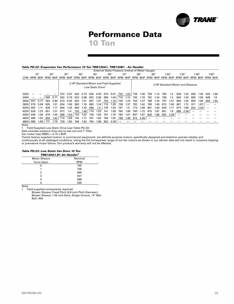
Table PD-22: Evaporator Fan Performance 10 Ton TWE120A1, TWE120B1 - Air Handler
Note:1 Field Supplied Low Static Drive (use Table PD-23)Data includes pressure drop due to wet coil and 1" filter.Fan motor heat (MBh) = 3.15 x BHP.Trane’s factory supplied motors, in commercial equipment, are definite purpose motors, specifically designed and tested to operate reliably and continuously at all cataloged conditions. Using the full horsepower range of our fan motors as shown in our tabular data will not result in nuisance tripping or premature motor failure. Our product’s warranty will not be affected.
Note:1 Field supplied components required:
Blower Sheave: Fixed Pitch (8.8 inch Pitch Diameter),Blower Sheave: 1.00 inch Bore, Single Groove, "A" Belt.Belt: A54
External Static Pressure (Inches of Water Gauge).10" .20" .30" .40" .50" .60" .70" .80" .90" 1.00" 1.20" 1.40" 1.60"
CFM RPM BHP RPM BHP RPM BHP RPM BHP RPM BHP RPM BHP RPM BHP RPM BHP RPM BHP RPM BHP RPM BHP RPM BHP RPM BHP
2 HP Standard Motor and Field Supplied Low Static Drive1
2 HP Standard Motor and Sheaves
3200 — — — — 570 0.67 603 0.75 636 0.83 670 0.91 703 1.00 736 1.08 756 1.14 784 1.2 838 1.32 890 1.49 942 1.663400 — — 560 0.71 592 0.79 623 0.88 652 0.95 685 1.04 716 1.12 743 1.18 762 1.24 790 1.3 844 1.43 895 1.59 948 1.83600 557 0.77 583 0.84 613 0.92 643 1.01 667 1.07 700 1.16 730 1.23 750 1.27 768 1.34 797 1.41 850 1.55 900 1.69 954 1.943800 579 0.94 605 1.01 634 1.09 663 1.18 683 1.24 710 1.29 738 1.37 762 1.42 785 1.49 813 1.56 861 1.72 911 1.87 — —4000 602 1.11 628 1.17 656 1.26 683 1.35 698 1.4 720 1.43 747 1.5 773 1.58 801 1.64 829 1.71 872 1.89 922 2.04 — —4200 626 1.23 651 1.31 677 1.4 703 1.48 714 1.53 741 1.59 765 1.66 790 1.72 815 1.81 841 1.9 888 2.08 — — — —4400 649 1.36 674 1.45 698 1.53 723 1.62 729 1.65 761 1.76 784 1.81 807 1.87 830 1.98 852 2.09 — — — — — —4600 669 1.52 692 1.62 714 1.69 735 1.77 747 1.82 782 1.92 798 1.99 815 2.06 — — — — — — — — — —4800 689 1.69 711 1.79 729 1.85 746 1.92 764 1.98 802 2.09 — — — — — — — — — — — — — —
Table PD-23: Low Static Fan Drive 10 Ton TWE120A1,B1 Air Handler1
Motor SheaveTurns Open
NominalRPM
0 7451 7062 6663 6274 5885 549
Performance Data10 Ton
24 SSP-PRC001-EN
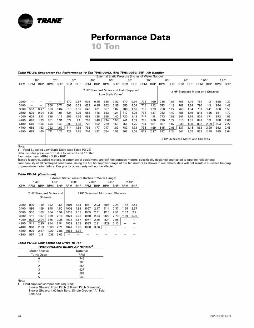
Table PD-24: Evaporator Fan Performance 10 Ton TWE120A3, AW; TWE120B3, BW - Air Handler
Note:1 Field Supplied Low Static Drive (use Table PD-25)Data includes pressure drop due to wet coil and 1" filter.Fan motor heat (MBh) = 3.15 x BHP.Trane’s factory supplied motors, in commercial equipment, are definite purpose motors, specifically designed and tested to operate reliably and continuously at all cataloged conditions. Using the full horsepower range of our fan motors as shown in our tabular data will not result in nuisance tripping or premature motor failure. Our product’s warranty will not be affected.
Table PD-24: (Continued)
Note:1 Field supplied components required:
Blower Sheave: Fixed Pitch (8.8 inch Pitch Diameter),Blower Sheave: 1.00 inch Bore, Single Groove, "A" Belt.Belt: A54
External Static Pressure (Inches of Water Gauge).10" .20" .30" .40" .50" .60" .70" .80" .90" 1.00" 1.20"
CFM RPM BHP RPM BHP RPM BHP RPM BHP RPM BHP RPM BHP RPM BHP RPM BHP RPM BHP RPM BHP RPM BHP
2 HP Standard Motor and Field Supplied Low Static Drive1
2 HP Standard Motor and Sheaves
3200 — — — — 570 0.67 603 0.75 636 0.83 670 0.91 703 1.00 736 1.08 756 1.14 784 1.2 838 1.323400 — — 560 0.71 592 0.79 623 0.88 652 0.95 685 1.04 716 1.12 743 1.18 762 1.24 790 1.3 844 1.433600 557 0.77 583 0.84 613 0.92 643 1.01 667 1.07 700 1.16 730 1.23 750 1.27 768 1.34 797 1.41 850 1.553800 579 0.94 605 1.01 634 1.09 663 1.18 683 1.24 710 1.29 738 1.37 762 1.42 785 1.49 813 1.56 861 1.724000 602 1.11 628 1.17 656 1.26 683 1.35 698 1.40 720 1.43 747 1.5 773 1.58 801 1.64 829 1.71 872 1.894200 626 1.23 651 1.31 677 1.4 703 1.48 714 1.53 741 1.59 765 1.66 790 1.72 815 1.81 841 1.9 888 2.084400 649 1.36 674 1.45 698 1.53 723 1.62 729 1.65 761 1.76 784 1.81 807 1.87 830 1.98 852 2.09 904 2.274700 669 1.52 792 1.62 714 1.69 735 1.77 747 1.82 782 1.92 798 1.99 815 2.06 837 2.18 862 2.29 922 2.454800 689 1.69 711 1.79 729 1.85 746 1.92 764 1.98 802 2.09 812 2.17 822 2.24 844 2.39 872 2.48 939 2.64
3 HP Oversized Motor and Sheaves
External Static Pressure (Inches of Water Gauge)1.40" 1.60" 1.80" 2.00" 2.20" 2.40"
CFM RPM BHP RPM BHP RPM BHP RPM BHP RPM BHP RPM BHP
2 HP Standard Motor and Sheaves
3 HP Oversized Motor and Sheaves
3200 890 1.49 942 1.66 1001 1.84 1051 2.03 1106 2.24 1162 2.443400 895 1.59 948 1.80 1009 1.98 1057 2.17 1111 2.37 1165 2.573600 900 1.69 954 1.94 1016 2.13 1065 2.31 1115 2.51 1167 2.73800 911 1.87 959 2.15 1024 2.35 1070 2.54 1120 2.73 1169 2.924000 922 2.04 965 2.36 1031 2.57 1077 2.76 1124 2.95 — —4200 941 2.29 984 2.54 1039 2.73 1083 2.91 1129 3.10 — —4400 960 2.53 1003 2.71 1047 2.89 1090 3.06 — — — —4600 979 2.67 1020 2.86 1061 3.06 — — — — — —4800 997 2.8 1036 3.02 — — — — — — — —
Table PD-25: Low Static Fan Drive 10 Ton TWE120A3,AW; BE,BW Air Handler1
Motor SheaveTurns Open
NominalRPM
0 7451 7062 6663 6274 5885 549
Performance Data10 Ton
SSP-PRC001-EN 25
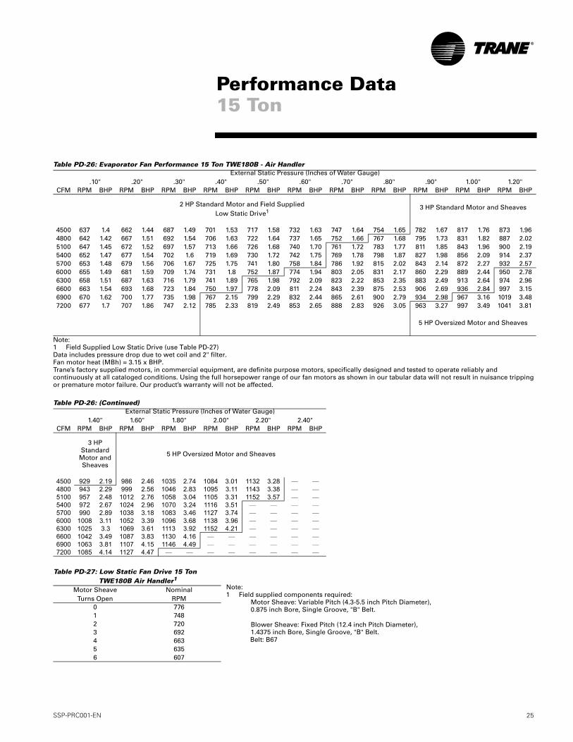
Table PD-26: Evaporator Fan Performance 15 Ton TWE180B - Air Handler
Note:1 Field Supplied Low Static Drive (use Table PD-27)Data includes pressure drop due to wet coil and 2" filter.Fan motor heat (MBh) = 3.15 x BHP.Trane’s factory supplied motors, in commercial equipment, are definite purpose motors, specifically designed and tested to operate reliably and continuously at all cataloged conditions. Using the full horsepower range of our fan motors as shown in our tabular data will not result in nuisance tripping or premature motor failure. Our product’s warranty will not be affected.
Table PD-26: (Continued)
External Static Pressure (Inches of Water Gauge).10" .20" .30" .40" .50" .60" .70" .80" .90" 1.00" 1.20"
CFM RPM BHP RPM BHP RPM BHP RPM BHP RPM BHP RPM BHP RPM BHP RPM BHP RPM BHP RPM BHP RPM BHP
2 HP Standard Motor and Field Supplied Low Static Drive1
3 HP Standard Motor and Sheaves
4500 637 1.4 662 1.44 687 1.49 701 1.53 717 1.58 732 1.63 747 1.64 754 1.65 782 1.67 817 1.76 873 1.964800 642 1.42 667 1.51 692 1.54 706 1.63 722 1.64 737 1.65 752 1.66 767 1.68 795 1.73 831 1.82 887 2.025100 647 1.45 672 1.52 697 1.57 713 1.66 726 1.68 740 1.70 761 1.72 783 1.77 811 1.85 843 1.96 900 2.195400 652 1.47 677 1.54 702 1.6 719 1.69 730 1.72 742 1.75 769 1.78 798 1.87 827 1.98 856 2.09 914 2.375700 653 1.48 679 1.56 706 1.67 725 1.75 741 1.80 758 1.84 786 1.92 815 2.02 843 2.14 872 2.27 932 2.576000 655 1.49 681 1.59 709 1.74 731 1.8 752 1.87 774 1.94 803 2.05 831 2.17 860 2.29 889 2.44 950 2.786300 658 1.51 687 1.63 716 1.79 741 1.89 765 1.98 792 2.09 823 2.22 853 2.35 883 2.49 913 2.64 974 2.966600 663 1.54 693 1.68 723 1.84 750 1.97 778 2.09 811 2.24 843 2.39 875 2.53 906 2.69 936 2.84 997 3.156900 670 1.62 700 1.77 735 1.98 767 2.15 799 2.29 832 2.44 865 2.61 900 2.79 934 2.98 967 3.16 1019 3.487200 677 1.7 707 1.86 747 2.12 785 2.33 819 2.49 853 2.65 888 2.83 926 3.05 963 3.27 997 3.49 1041 3.81
5 HP Oversized Motor and Sheaves
External Static Pressure (Inches of Water Gauge)1.40" 1.60" 1.80" 2.00" 2.20" 2.40"
CFM RPM BHP RPM BHP RPM BHP RPM BHP RPM BHP RPM BHP
3 HP Standard
Motor and Sheaves
5 HP Oversized Motor and Sheaves
4500 929 2.19 986 2.46 1035 2.74 1084 3.01 1132 3.28 — —4800 943 2.29 999 2.56 1046 2.83 1095 3.11 1143 3.38 — —5100 957 2.48 1012 2.76 1058 3.04 1105 3.31 1152 3.57 — —5400 972 2.67 1024 2.96 1070 3.24 1116 3.51 — — — —5700 990 2.89 1038 3.18 1083 3.46 1127 3.74 — — — —6000 1008 3.11 1052 3.39 1096 3.68 1138 3.96 — — — —6300 1025 3.3 1069 3.61 1113 3.92 1152 4.21 — — — —6600 1042 3.49 1087 3.83 1130 4.16 — — — — — —6900 1063 3.81 1107 4.15 1146 4.49 — — — — — —7200 1085 4.14 1127 4.47 — — — — — — — —
Table PD-27: Low Static Fan Drive 15 Ton TWE180B Air Handler1
Motor SheaveTurns Open
NominalRPM
0 7761 7482 7203 6924 6635 6356 607
Performance Data15 Ton
Note:1 Field supplied components required:
Motor Sheave: Variable Pitch (4.3-5.5 inch Pitch Diameter),0.875 inch Bore, Single Groove, "B" Belt.
Blower Sheave: Fixed Pitch (12.4 inch Pitch Diameter),1.4375 inch Bore, Single Groove, "B" Belt.Belt: B67
26 SSP-PRC001-EN
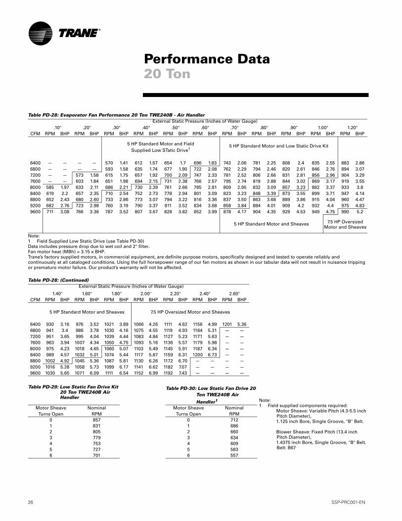
Table PD-28: Evaporator Fan Performance 20 Ton TWE240B - Air Handler
Note:1 Field Supplied Low Static Drive (use Table PD-30)Data includes pressure drop due to wet coil and 2" filter.Fan motor heat (MBh) = 3.15 x BHP.Trane’s factory supplied motors, in commercial equipment, are definite purpose motors, specifically designed and tested to operate reliably and continuously at all cataloged conditions. Using the full horsepower range of our fan motors as shown in our tabular data will not result in nuisance tripping or premature motor failure. Our product’s warranty will not be affected.
Table PD-28: (Continued)
External Static Pressure (Inches of Water Gauge).10" .20" .30" .40" .50" .60" .70" .80" .90" 1.00" 1.20"
CFM RPM BHP RPM BHP RPM BHP RPM BHP RPM BHP RPM BHP RPM BHP RPM BHP RPM BHP RPM BHP RPM BHP
5 HP Standard Motor and Field Supplied Low STatic Drive1
5 HP Standard Motor and Low Static Drive Kit
6400 — — — — 570 1.41 612 1.57 654 1.7 696 1.83 743 2.06 781 2.25 808 2.4 835 2.55 883 2.866800 — — — — 593 1.58 635 1.74 677 1.90 722 2.08 762 2.29 794 2.46 820 2.61 846 2.76 894 3.077200 — — 573 1.58 615 1.75 657 1.92 700 2.09 747 2.33 781 2.52 806 2.66 831 2.81 856 2.96 904 3.297600 — — 603 1.84 651 1.98 694 2.15 731 2.38 766 2.57 795 2.74 819 2.88 844 3.02 869 3.17 919 3.558000 585 1.97 633 2.11 686 2.21 730 2.39 761 2.66 785 2.81 809 2.95 832 3.09 857 3.23 882 3.37 933 3.88400 619 2.2 657 2.35 710 2.54 752 2.73 778 2.94 801 3.09 823 3.23 848 3.39 873 3.55 899 3.71 947 4.148800 652 2.43 680 2.60 733 2.86 773 3.07 794 3.22 816 3.36 837 3.50 863 3.68 889 3.86 915 4.04 960 4.479200 682 2.76 723 2.98 760 3.19 790 3.37 811 3.52 834 3.68 858 3.84 884 4.01 909 4.2 932 4.4 975 4.839600 711 3.08 766 3.36 787 3.52 807 3.67 828 3.82 852 3.99 878 4.17 904 4.35 929 4.53 949 4.75 990 5.2
5 HP Standard Motor and Sheaves 7.5 HP Oversized Motor and Sheaves
External Static Pressure (Inches of Water Gauge)
1.40" 1.60" 1.80" 2.00" 2.20" 2.40" 2.60"CFM RPM BHP RPM BHP RPM BHP RPM BHP RPM BHP RPM BHP RPM BHP
5 HP Standard Motor and Sheaves 7.5 HP Oversized Motor and Sheaves
6400 930 3.16 976 3.52 1021 3.89 1066 4.26 1111 4.62 1156 4.99 1201 5.366800 941 3.4 986 3.78 1030 4.16 1075 4.55 1119 4.93 1164 5.31 — —7200 951 3.65 995 4.04 1039 4.44 1083 4.84 1127 5.23 1171 5.63 — —7600 963 3.94 1007 4.34 1050 4.75 1093 5.16 1136 5.57 1179 5.98 — —8000 975 4.23 1018 4.65 1060 5.07 1103 5.49 1145 5.91 1187 6.34 — —8400 989 4.57 1032 5.01 1074 5.44 1117 5.87 1159 6.31 1200 6.73 — —8800 1002 4.92 1045 5.36 1087 5.81 1130 6.26 1172 6.70 — — — —9200 1016 5.28 1058 5.73 1099 6.17 1141 6.62 1182 7.07 — — — —9600 1030 5.65 1071 6.09 1111 6.54 1152 6.99 1192 7.43 — — — —
Table PD-29: Low Static Fan Drive Kit 20 Ton TWE240B Air Handler
Table PD-30: Low Static Fan Drive 20 Ton TWE240B Air
Handler1
Motor SheaveTurns Open
NominalRPM
Motor SheaveTurns Open
NominalRPM
0 857 0 7121 831 1 6862 805 2 6603 779 3 6344 753 4 6095 727 5 5836 701 6 557
Performance Data20 Ton
Note:1 Field supplied components required:
Motor Sheave: Variable Pitch (4.3-5.5 inch Pitch Diameter),1.125 inch Bore, Single Groove, "B" Belt.
Blower Sheave: Fixed Pitch (13.4 inch Pitch Diameter),1.4375 inch Bore, Single Groove, "B" Belt.Belt: B67
SSP-PRC001-EN 27
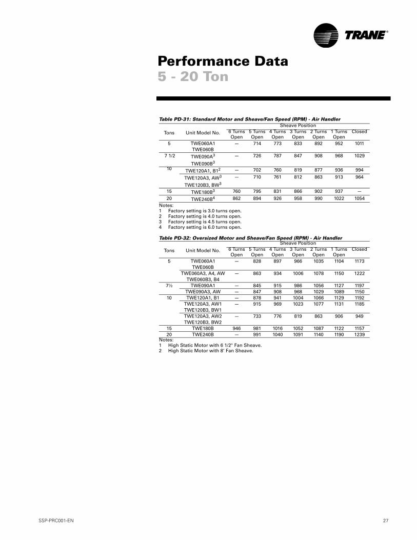
Table PD-31: Standard Motor and Sheave/Fan Speed (RPM) - Air Handler
Notes:1 Factory setting is 3.0 turns open.2 Factory setting is 4.0 turns open.3 Factory setting is 4.5 turns open.4 Factory setting is 6.0 turns open.
Table PD-32: Oversized Motor and Sheave/Fan Speed (RPM) - Air Handler
Notes:1 High Static Motor with 6 1/2" Fan Sheave.2 High Static Motor with 8’ Fan Sheave.
Sheave Position
Tons Unit Model No. 6 Turns Open
5 Turns Open
4 Turns Open
3 Turns Open
2 Turns Open
1 Turns Open
Closed
5 TWE060A1 — 714 773 833 892 952 1011TWE060B
7 1/2 TWE090A3 — 726 787 847 908 968 1029
TWE090B3
10 TWE120A1, B12 — 702 760 819 877 936 994
TWE120A3, AW3 — 710 761 812 863 913 964
TWE120B3, BW3
15 TWE180B3 760 795 831 866 902 937 —
20 TWE240B4 862 894 926 958 990 1022 1054
Sheave Position
Tons Unit Model No. 6 Turns Open
5 Turns Open
4 Turns Open
3 Turns Open
2 Turns Open
1 Turns Open
Closed
5 TWE060A1 — 828 897 966 1035 1104 1173TWE060B
TWE060A3, A4, AW — 863 934 1006 1078 1150 1222TWE060B3, B4
7½ TWE090A1 — 845 915 986 1056 1127 1197TWE090A3, AW — 847 908 968 1029 1089 1150
10 TWE120A1, B1 — 878 941 1004 1066 1129 1192TWE120A3, AW1 — 915 969 1023 1077 1131 1185TWE120B3, BW1TWE120A3, AW2 — 733 776 819 863 906 949TWE120B3, BW2
15 TWE180B 946 981 1016 1052 1087 1122 115720 TWE240B — 991 1040 1091 1140 1190 1239
Performance Data5 - 20 Ton
28 SSP-PRC001-EN
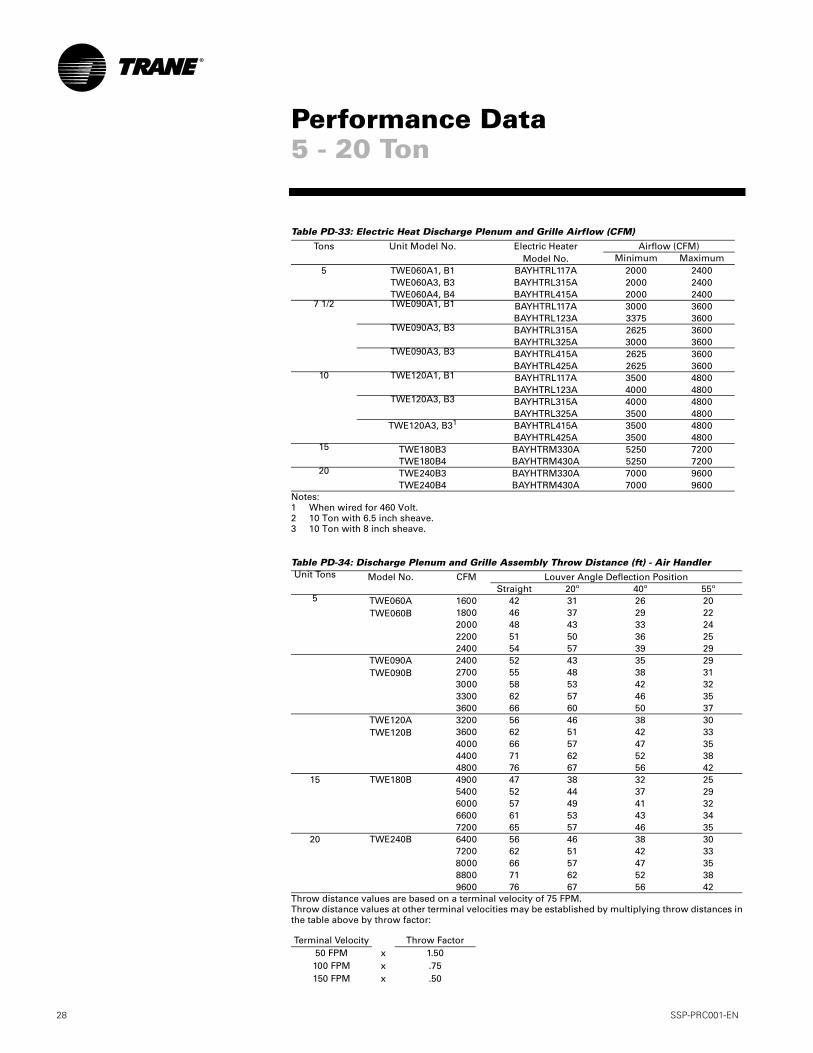
Table PD-33: Electric Heat Discharge Plenum and Grille Airflow (CFM)
Notes:1 When wired for 460 Volt.2 10 Ton with 6.5 inch sheave.3 10 Ton with 8 inch sheave.
Table PD-34: Discharge Plenum and Grille Assembly Throw Distance (ft) - Air Handler
Throw distance values are based on a terminal velocity of 75 FPM.Throw distance values at other terminal velocities may be established by multiplying throw distances inthe table above by throw factor:
Tons Unit Model No. Electric HeaterModel No.
Airflow (CFM)Minimum Maximum
5 TWE060A1, B1 BAYHTRL117A 2000 2400TWE060A3, B3 BAYHTRL315A 2000 2400TWE060A4, B4 BAYHTRL415A 2000 2400
7 1/2 TWE090A1, B1 BAYHTRL117A 3000 3600BAYHTRL123A 3375 3600
TWE090A3, B3 BAYHTRL315A 2625 3600BAYHTRL325A 3000 3600
TWE090A3, B3 BAYHTRL415A 2625 3600BAYHTRL425A 2625 3600
10 TWE120A1, B1 BAYHTRL117A 3500 4800BAYHTRL123A 4000 4800
TWE120A3, B3 BAYHTRL315A 4000 4800BAYHTRL325A 3500 4800
TWE120A3, B31 BAYHTRL415A 3500 4800BAYHTRL425A 3500 4800
15 TWE180B3 BAYHTRM330A 5250 7200TWE180B4 BAYHTRM430A 5250 7200
20 TWE240B3 BAYHTRM330A 7000 9600TWE240B4 BAYHTRM430A 7000 9600
Unit Tons Model No. CFM Louver Angle Deflection PositionStraight 20º 40º 55º
5 TWE060ATWE060B
1600 42 31 26 201800 46 37 29 222000 48 43 33 242200 51 50 36 252400 54 57 39 29
TWE090ATWE090B
2400 52 43 35 292700 55 48 38 313000 58 53 42 323300 62 57 46 353600 66 60 50 37
TWE120ATWE120B
3200 56 46 38 303600 62 51 42 334000 66 57 47 354400 71 62 52 384800 76 67 56 42
15 TWE180B 4900 47 38 32 255400 52 44 37 296000 57 49 41 326600 61 53 43 347200 65 57 46 35
20 TWE240B 6400 56 46 38 307200 62 51 42 338000 66 57 47 358800 71 62 52 389600 76 67 56 42
Terminal Velocity Throw Factor50 FPM x 1.50100 FPM x .75150 FPM x .50
Performance Data5 - 20 Ton
SSP-PRC001-EN 29
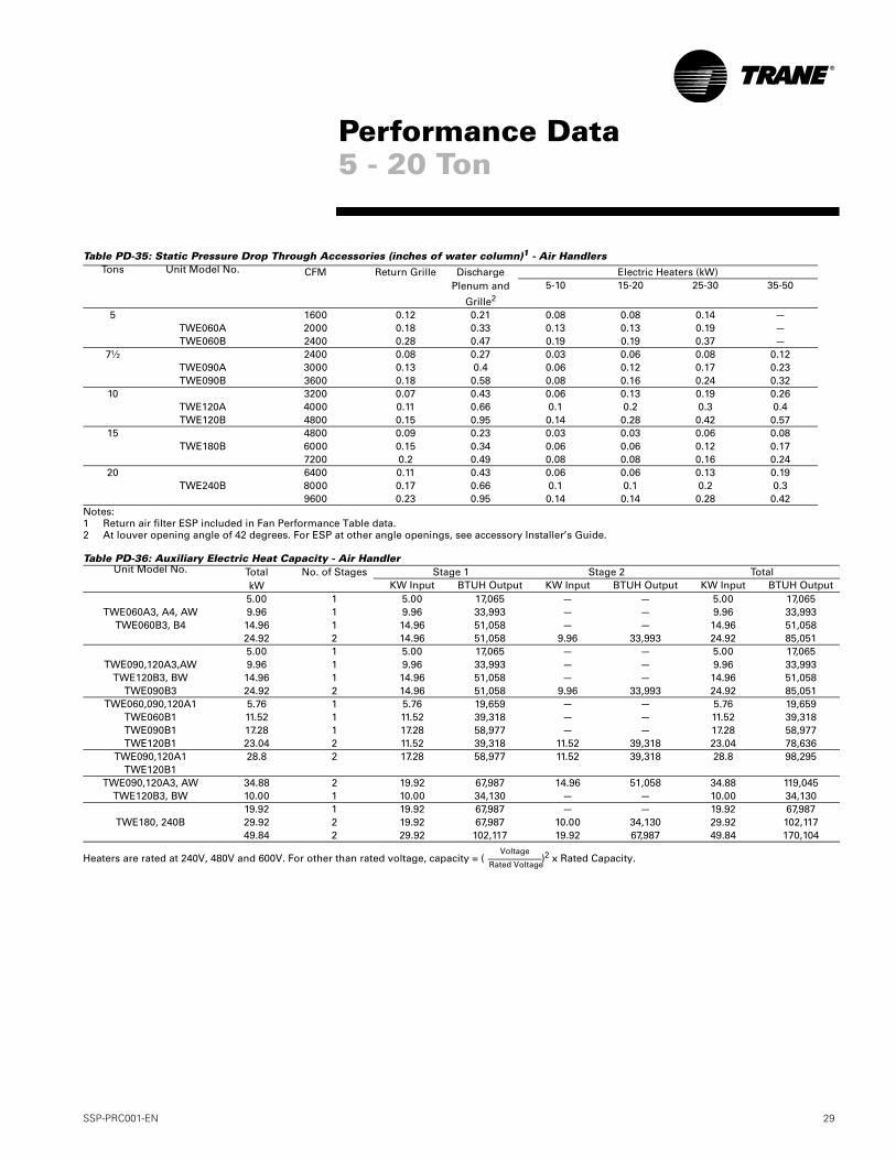
Table PD-35: Static Pressure Drop Through Accessories (inches of water column)1 - Air Handlers
Notes:1 Return air filter ESP included in Fan Performance Table data.2 At louver opening angle of 42 degrees. For ESP at other angle openings, see accessory Installer’s Guide.
Table PD-36: Auxiliary Electric Heat Capacity - Air Handler
Heaters are rated at 240V, 480V and 600V. For other than rated voltage, capacity = ( )2 x Rated Capacity.
Tons Unit Model No. CFM Return Grille Discharge Plenum and
Grille2
Electric Heaters (kW)5-10 15-20 25-30 35-50
5 1600 0.12 0.21 0.08 0.08 0.14 —TWE060A 2000 0.18 0.33 0.13 0.13 0.19 —TWE060B 2400 0.28 0.47 0.19 0.19 0.37 —
7½ 2400 0.08 0.27 0.03 0.06 0.08 0.12TWE090A 3000 0.13 0.4 0.06 0.12 0.17 0.23TWE090B 3600 0.18 0.58 0.08 0.16 0.24 0.32
10 3200 0.07 0.43 0.06 0.13 0.19 0.26TWE120A 4000 0.11 0.66 0.1 0.2 0.3 0.4TWE120B 4800 0.15 0.95 0.14 0.28 0.42 0.57
15 4800 0.09 0.23 0.03 0.03 0.06 0.08TWE180B 6000 0.15 0.34 0.06 0.06 0.12 0.17
7200 0.2 0.49 0.08 0.08 0.16 0.2420 6400 0.11 0.43 0.06 0.06 0.13 0.19
TWE240B 8000 0.17 0.66 0.1 0.1 0.2 0.39600 0.23 0.95 0.14 0.14 0.28 0.42
Unit Model No. TotalkW
No. of Stages Stage 1 Stage 2 TotalKW Input BTUH Output KW Input BTUH Output KW Input BTUH Output
5.00 1 5.00 17,065 — — 5.00 17,065TWE060A3, A4, AW 9.96 1 9.96 33,993 — — 9.96 33,993
TWE060B3, B4 14.96 1 14.96 51,058 — — 14.96 51,05824.92 2 14.96 51,058 9.96 33,993 24.92 85,0515.00 1 5.00 17,065 — — 5.00 17,065
TWE090,120A3,AW 9.96 1 9.96 33,993 — — 9.96 33,993TWE120B3, BW 14.96 1 14.96 51,058 — — 14.96 51,058
TWE090B3 24.92 2 14.96 51,058 9.96 33,993 24.92 85,051TWE060,090,120A1 5.76 1 5.76 19,659 — — 5.76 19,659
TWE060B1 11.52 1 11.52 39,318 — — 11.52 39,318TWE090B1 17.28 1 17.28 58,977 — — 17.28 58,977TWE120B1 23.04 2 11.52 39,318 11.52 39,318 23.04 78,636
TWE090,120A1 28.8 2 17.28 58,977 11.52 39,318 28.8 98,295TWE120B1
TWE090,120A3, AW 34.88 2 19.92 67,987 14.96 51,058 34.88 119,045TWE120B3, BW 10.00 1 10.00 34,130 — — 10.00 34,130
19.92 1 19.92 67,987 — — 19.92 67,987TWE180, 240B 29.92 2 19.92 67,987 10.00 34,130 29.92 102,117
49.84 2 29.92 102,117 19.92 67,987 49.84 170,104
Performance Data5 - 20 Ton
Voltage
Rated Voltage
30 SSP-PRC001-EN
Thermostats - Two stage heating/ cooling or one stage heating/cooling thermostats are available in either manual or automatic changeover.
Programmable Electronic Night Set-back Thermostat — Heating setback and cooling setup with 7-day, 5-1-1 programming capability. Available in 2 heating/cooling or 1 heating/cooling versions with automatic changeover.
Controls
SSP-PRC001-EN 31
ElectricalData
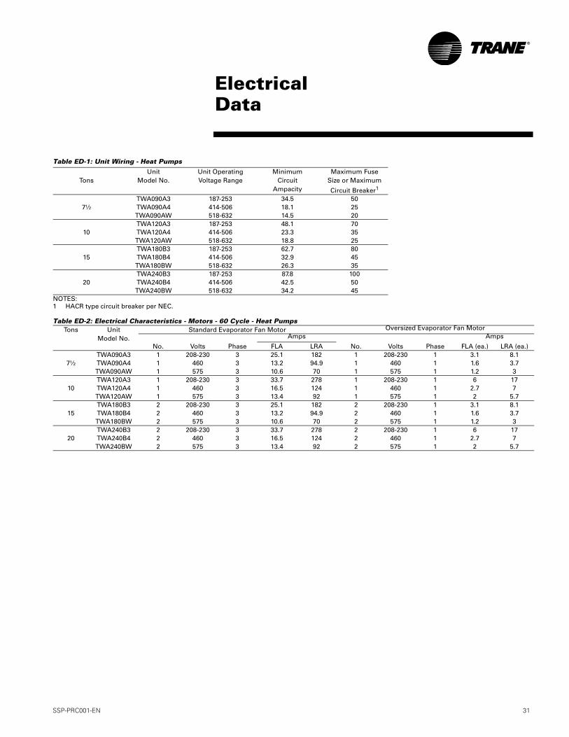
Table ED-1: Unit Wiring - Heat Pumps
NOTES:1 HACR type circuit breaker per NEC.
Table ED-2: Electrical Characteristics - Motors - 60 Cycle - Heat Pumps
Tons
UnitModel No.
Unit OperatingVoltage Range
MinimumCircuit
Ampacity
Maximum FuseSize or Maximum
Circuit Breaker1
TWA090A3 187-253 34.5 507½ TWA090A4 414-506 18.1 25
TWA090AW 518-632 14.5 20TWA120A3 187-253 48.1 70
10 TWA120A4 414-506 23.3 35TWA120AW 518-632 18.8 25TWA180B3 187-253 62.7 80
15 TWA180B4 414-506 32.9 45TWA180BW 518-632 26.3 35TWA240B3 187-253 87.8 100
20 TWA240B4 414-506 42.5 50TWA240BW 518-632 34.2 45
Tons UnitModel No.
Standard Evaporator Fan Motor Oversized Evaporator Fan MotorAmps Amps
No. Volts Phase FLA LRA No. Volts Phase FLA (ea.) LRA (ea.)TWA090A3 1 208-230 3 25.1 182 1 208-230 1 3.1 8.1
7½ TWA090A4 1 460 3 13.2 94.9 1 460 1 1.6 3.7TWA090AW 1 575 3 10.6 70 1 575 1 1.2 3TWA120A3 1 208-230 3 33.7 278 1 208-230 1 6 17
10 TWA120A4 1 460 3 16.5 124 1 460 1 2.7 7TWA120AW 1 575 3 13.4 92 1 575 1 2 5.7TWA180B3 2 208-230 3 25.1 182 2 208-230 1 3.1 8.1
15 TWA180B4 2 460 3 13.2 94.9 2 460 1 1.6 3.7TWA180BW 2 575 3 10.6 70 2 575 1 1.2 3TWA240B3 2 208-230 3 33.7 278 2 208-230 1 6 17
20 TWA240B4 2 460 3 16.5 124 2 460 1 2.7 7TWA240BW 2 575 3 13.4 92 2 575 1 2 5.7
32 SSP-PRC001-EN
ElectricalData
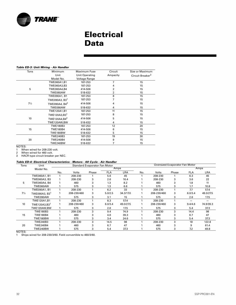
Table ED-3: Unit Wiring - Air Handler
NOTES:1 When wired for 208-230 volt.2 When wired for 460 volt.3 HACR type circuit breaker per NEC.
Table ED-4: Electrical Characteristics - Motors - 60 Cycle - Air Handler
NOTES:1 Ships wired for 208-230/3/60. Field convertible to 460/3/60.
Tons MinimumUnit
Model No.
Maximum FuseUnit OperatingVoltage Range
CircuitAmpacity
Size or Maximum
Circuit Breaker3
TWE060A1,B1 187-253 7 15TWE060A3,B3 187-253 4 15
5 TWE060A4,B4 414-506 2 15TWE060AW 518-632 2 15
TWE090A1, B1 187-253 8 15
TWE090A3, B31 187-253 7 15
7½ TWE090A4, B42 414-506 4 15
TWE090AW 518-632 4 15TWE120A1,B1 187-253 11 15
TWE120A3,B31 187-253 8 15
10 TWE120A4,B42 414-506 5 15TWE120AW,BW 518-632 4 15
TWE180B3 187-253 12 2015 TWE180B4 414-506 6 15
TWE180BW 518-632 5 15TWE240B3 187-253 19 30
20 TWE240B4 414-506 9 15TWE240BW 518-632 7 15
Tons UnitModel No.
Standard Evaporator Fan Motor Oversized Evaporator Fan MotorAmps Amps
No. Volts Phase FLA LRA No. Volts Phase FLA LRATWE060A1, B1 1 208-230 1 5.6 45 1 208-230 1 6.3 45TWE060A3, B3 1 208-230 3 2.6 16.4 1 208-230 3 3.6 22
5 TWE060A4, B4 1 460 3 1.3 8.2 1 460 3 1.8 11TWE060AW 1 575 3 1.3 6.6 1 575 3 1.7 10.8
TWE090A1, B1 1 208-230 1 6.2 33 1 208-230 1 7.7 57.47½ TWE090A3, B31 1 208-230/460 3 5.0/2.5 34.3/17.0 1 208-230/460 3 6.0/3.4 49.0/27.5
TWE090AW 1 575 3 3.1 15 1 575 3 2.6 17.5TWE120A1,B1 1 208-230 1 8.3 57.4 1 208-230 1 — —
10 TWE120A3,B31 1 208-230/460 3 6.0/3.4 49.0/27.5 1 208-230/460 3 9.4/4.6 74.9/39.3
TWE120AW,BW 1 575 3 2.6 17.5 1 575 3 5.4 37.3TWE180B3 1 208-230 3 9.4 74.9 1 208-230 3 14.4 98
15 TWE180B4 1 460 3 4.6 39.3 1 460 3 6.7 47TWE180BW 1 575 3 3.4 24.6 1 575 3 5.4 37.3TWE240B3 1 208-230 3 14.5 98 1 208-230 3 18 122.8
20 TWE240B4 1 460 3 6.7 47 1 460 3 9 61.4TWE240BW 1 575 3 5.4 37.3 1 575 3 7.2 49.8
SSP-PRC001-EN 33
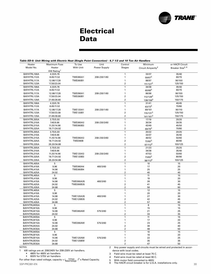
Table ED-5: Unit Wiring with Electric Heat (Single Point Connection) - 5,7 1/2 and 10 Ton Air HandlersHeater
Model No.Maximum Fuse
Heater
KW Rating1
To UseWith Unit
UnitPower Supply
ControlStages
Minimum
Circuit Ampacity2or HACR Circuit
Breaker Size2, 6
BAYHTRL106A 4.33/5.76 1 33/37 35/40BAYHTRL112A 8.65/11.52 TWE060A1 208-230/1/60 1 59/673 60/70BAYHTRL117A 12.98/17.28 TWE060B1 1 88/97 90/100BAYHTRL123A 17.30/23.04 2 111/1273 125/150BAYHTRL106A 4.33/5.76 1 34/38 35/40BAYHTRL112A 8.65/11.52 1 60/683 60/70
BAYHTRL117A 12.98/17.28 TWE090A1 208-230/1/60 1 86/98 90/100BAYHTRL123A 17.30/23.04 TWE090B1 2 112/1283 125/150BAYHTRL129A 21.65/28.80 2 138/1583 150/175BAYHTRL106A 4.33/5.76 1 31/41 40/45BAYHTRL112A 8.65/11.52 1 63/733 70/80
BAYHTRL117A 12.98/17.28 TWE120A1 208-230/1/60 1 89/101 90/110BAYHTRL123A 17.30/23.08 TWE120B1 2 115/1313 125/150BAYHTRL129A 21.65/28.80 2 141/1613 150/175BAYHTRL305A 3.75/5.00 1 17/19 20/20BAYHTRL310A 7.45/9.96 TWE060A3 208-230/3/60 1 30/34 30/35BAYHTRL315A 11.25/14.96 TWE060B3 1 43/49 45/50BAYHTRL325A 18.71/24.92 2 69/793 70/80BAYHTRL305A 3.75/5.00 1 20/22 20/25BAYHTRL310A 7.45/9.96 1 33/37 35/40BAYHTRL315A 11.25/14.96 TWE090A3 208-230/3/60 1 46/52 50/60BAYHTRL325A 18.71/24.92 TWE090B 2 72/823 80/90BAYHTRL335A 26.20/34.88 2 97/1124 100/125
BAYHTRL305A 3.75/5.00 1 21/23 25/25BAYHTRL310A 7.45/9.96 1 34/38 35/40BAYHTRL315A 11.25/14.96 TWE120A3 208-230/3/60 1 47/53 50/60BAYHTRL325A 18.71/24.92 TWE120B3 2 73/833 80/90BAYHTRL335A 26.20/34.88 2 98/1134 100/125BAYHTRL405A 5 1 10 15BAYHTRL410A 9.96 TWE060A4 460/3/60 1 17 20BAYHTRL415A 14.96 TWE060B4 1 25 25BAYHTRL425A 24.92 2 40 40BAYHTRL405A 5 1 11 15BAYHTRL410A 9.96 1 19 20BAYHTRL415A 14.96 TWE090A35 460/3/60 1 26 30BAYHTRL425A 24.92 TWE090B35 2 41 45BAYHTRL435A 34.88 2 56 60BAYHTRL405A 5 1 12 15BAYHTRL410A 9.96 1 20 20BAYHTRL415A 14.96 TWE120A35 460/3/60 1 27 30BAYHTRL425A 24.92 TWE120B35 2 42 45BAYHTRL435A 34.88 2 57 60BAYHTRLW05A 5 1 8 15BAYHTRLW10A 9.96 1 15 15BAYHTRLW15A 14.96 TWE060AW 575/3/60 1 21 25BAYHTRLW25A 24.92 2 33 35BAYHTRLW05A 5 1 11 15BAYHTRLW10A 9.96 1 17 20BAYHTRLW15A 14.96 TWE090AW 575/3/60 1 23 25BAYHTRLW25A 24.92 2 36 40BAYHTRLW35A 34.88 2 48 50BAYHTRLW05A 5 1 10 15BAYHTRLW10A 9.96 1 16 20BAYHTRLW15A 14.96 TWE120AW 575/3/60 1 22 25BAYHTRLW25A 24.92 TWE120BW 2 35 35BAYHTRLW35A 34.88 2 47 50
ElectricalData
NOTES:
1 kW ratings are at: 208/240V for 208-230V air handlers. • 480V for 460V air handlers • 600V for 575V air handlersFor other than rated voltage, capacity = ( )2 x Rated Capacity.Voltage
Rated Voltage
2 Any power supply and circuits must be wired and protected in accor-dance with local codes.
3 Field wire must be rated at least 75 C.4 Field wire must be rated at least 90 C.5 With motor field converted to 460V.6 The HACR circuit breaker is for U.S.A. installations only.
34 SSP-PRC001-EN
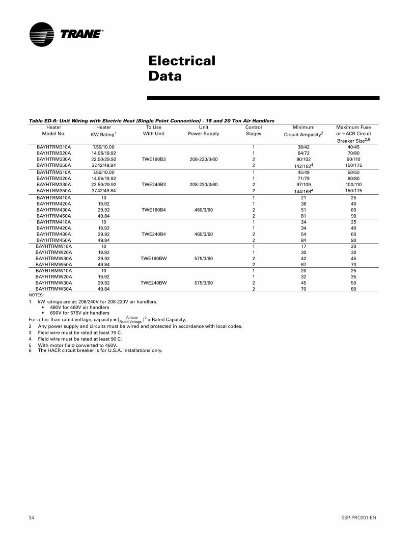
Table ED-6: Unit Wiring with Electric Heat (Single Point Connection) - 15 and 20 Ton Air Handlers
NOTES:
1 kW ratings are at: 208/240V for 208-230V air handlers. • 480V for 460V air handlers • 600V for 575V air handlersFor other than rated voltage, capacity = ( )2 x Rated Capacity.2 Any power supply and circuits must be wired and protected in accordance with local codes.3 Field wire must be rated at least 75 C.4 Field wire must be rated at least 90 C.5 With motor field converted to 460V.6 The HACR circuit breaker is for U.S.A. installations only.
HeaterModel No.
Heater
KW Rating1To Use
With UnitUnit
Power SupplyControlStages
Minimum
Circuit Ampacity2Maximum Fuseor HACR Circuit
Breaker Size2,6
BAYHTRM310A 7.50/10.00 1 38/42 40/45BAYHTRM320A 14.96/19.92 1 64/72 70/80BAYHTRM330A 22.50/29.92 TWE180B3 208-230/3/60 2 90/102 90/110BAYHTRM350A 37.42/49.84 2 142/1624 150/175
BAYHTRM310A 7.50/10.00 1 45/49 50/50BAYHTRM320A 14.96/19.92 1 71/79 80/80BAYHTRM330A 22.50/29.92 TWE240B3 208-230/3/60 2 97/109 100/110BAYHTRM350A 37.42/49.84 2 144/1694 150/175
BAYHTRM410A 10 1 21 25BAYHTRM420A 19.92 1 36 40BAYHTRM430A 29.92 TWE180B4 460/3/60 2 51 60BAYHTRM450A 49.84 2 81 90BAYHTRM410A 10 1 24 25BAYHTRM420A 19.92 1 34 40BAYHTRM430A 29.92 TWE240B4 460/3/60 2 54 60BAYHTRM450A 49.84 2 84 90BAYHTRMW10A 10 1 17 20BAYHTRMW20A 19.92 1 30 30BAYHTRMW30A 29.92 TWE180BW 575/3/60 2 42 45BAYHTRMW50A 49.84 2 67 70BAYHTRMW10A 10 1 20 25BAYHTRMW20A 19.92 1 32 35BAYHTRMW30A 29.92 TWE240BW 575/3/60 2 45 50BAYHTRMW50A 49.84 2 70 80
ElectricalData
VoltageRated Voltage
SSP-PRC001-EN 35
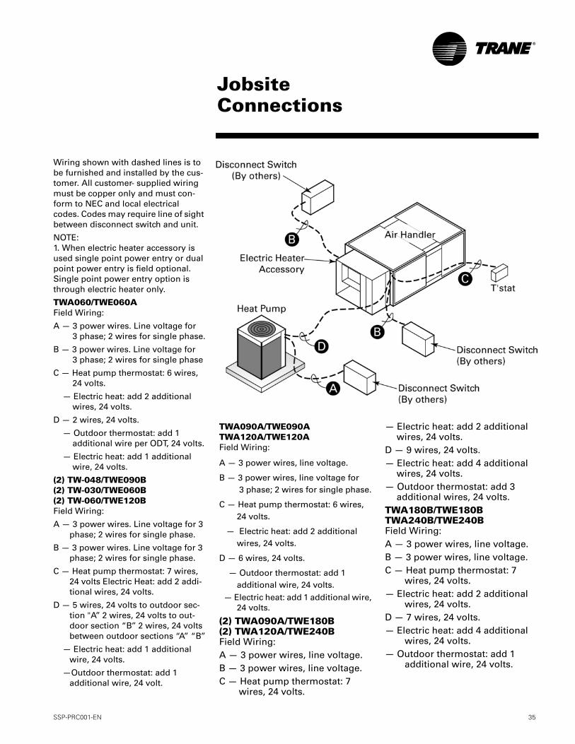
Wiring shown with dashed lines is to be furnished and installed by the cus-tomer. All customer- supplied wiring must be copper only and must con-form to NEC and local electrical codes. Codes may require line of sight between disconnect switch and unit.
NOTE:1. When electric heater accessory is used single point power entry or dual point power entry is field optional. Single point power entry option is through electric heater only.
TWA060/TWE060AField Wiring:
A — 3 power wires. Line voltage for 3 phase; 2 wires for single phase.
B — 3 power wires. Line voltage for 3 phase; 2 wires for single phase
C — Heat pump thermostat: 6 wires, 24 volts.
— Electric heat: add 2 additional wires, 24 volts.
D — 2 wires, 24 volts.
— Outdoor thermostat: add 1 additional wire per ODT, 24 volts.
— Electric heat: add 1 additional wire, 24 volts.
(2) TW-048/TWE090B(2) TW-030/TWE060B(2) TW-060/TWE120BField Wiring:
A — 3 power wires. Line voltage for 3 phase; 2 wires for single phase.
B — 3 power wires. Line voltage for 3 phase; 2 wires for single phase.
C — Heat pump thermostat: 7 wires, 24 volts Electric Heat: add 2 addi-tional wires, 24 volts.
D — 5 wires, 24 volts to outdoor sec-tion "A’’ 2 wires, 24 volts to out-door section “B’’ 2 wires, 24 volts between outdoor sections “A” “B’’
— Electric heat: add 1 additional wire, 24 volts.
—Outdoor thermostat: add 1 additional wire, 24 volt.
TWA090A/TWE090ATWA120A/TWE120AField Wiring:
A — 3 power wires, line voltage.
B — 3 power wires, line voltage for 3 phase; 2 wires for single phase.
C — Heat pump thermostat: 6 wires, 24 volts.
— Electric heat: add 2 additional wires, 24 volts.
D — 6 wires, 24 volts.
— Outdoor thermostat: add 1 additional wire, 24 volts.
— Electric heat: add 1 additional wire,24 volts.
(2) TWA090A/TWE180B(2) TWA120A/TWE240BField Wiring:A — 3 power wires, line voltage.B — 3 power wires, line voltage.C — Heat pump thermostat: 7
wires, 24 volts.
— Electric heat: add 2 additional wires, 24 volts.
D — 9 wires, 24 volts.— Electric heat: add 4 additional
wires, 24 volts.— Outdoor thermostat: add 3
additional wires, 24 volts.TWA180B/TWE180BTWA240B/TWE240BField Wiring:A — 3 power wires, line voltage.B — 3 power wires, line voltage.C — Heat pump thermostat: 7
wires, 24 volts.— Electric heat: add 2 additional
wires, 24 volts.D — 7 wires, 24 volts.— Electric heat: add 4 additional
wires, 24 volts.— Outdoor thermostat: add 1
additional wire, 24 volts.
JobsiteConnections
36 SSP-PRC001-EN
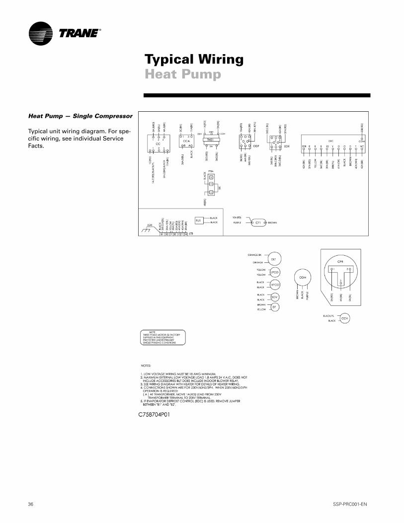
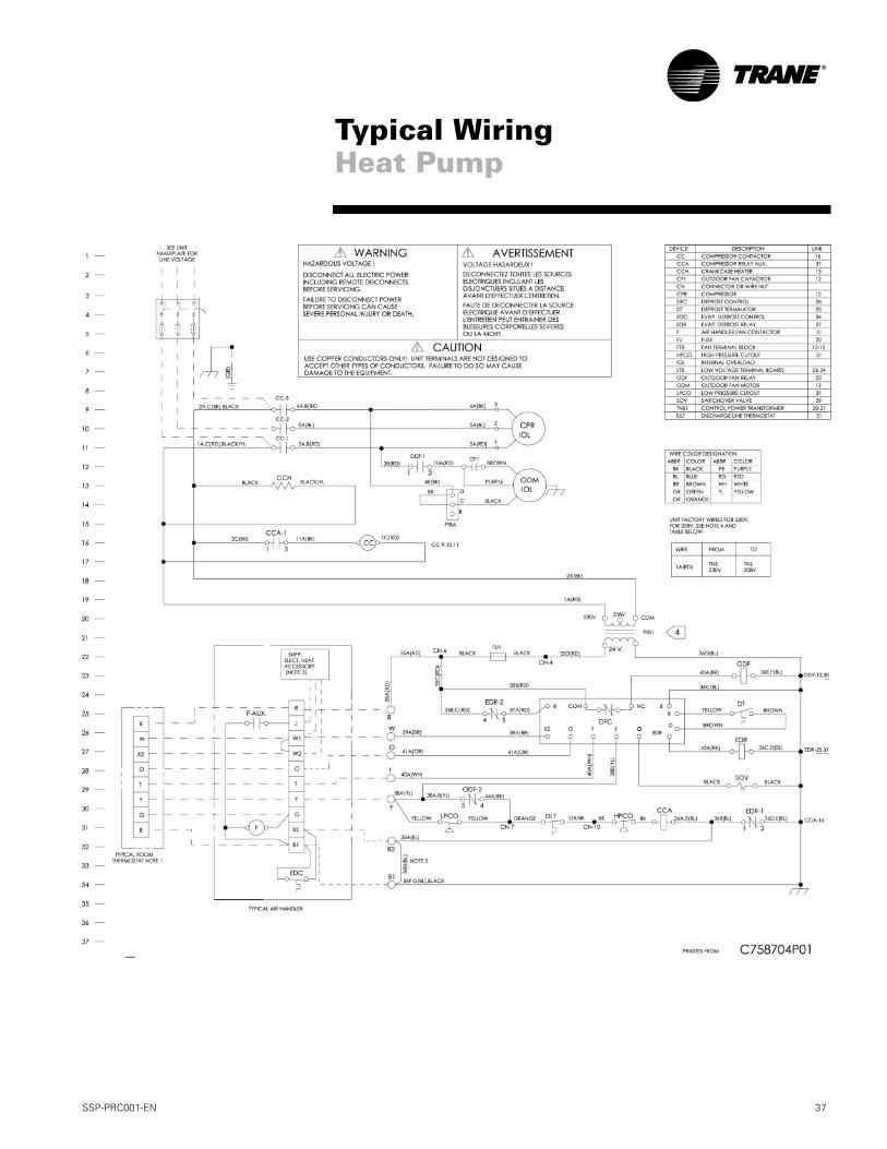
Heat Pump — Single Compressor
Typical unit wiring diagram. For spe-cific wiring, see individual Service Facts.
Typical WiringHeat Pump
SSP-PRC001-EN 37
Typical WiringHeat Pump
38 SSP-PRC001-EN
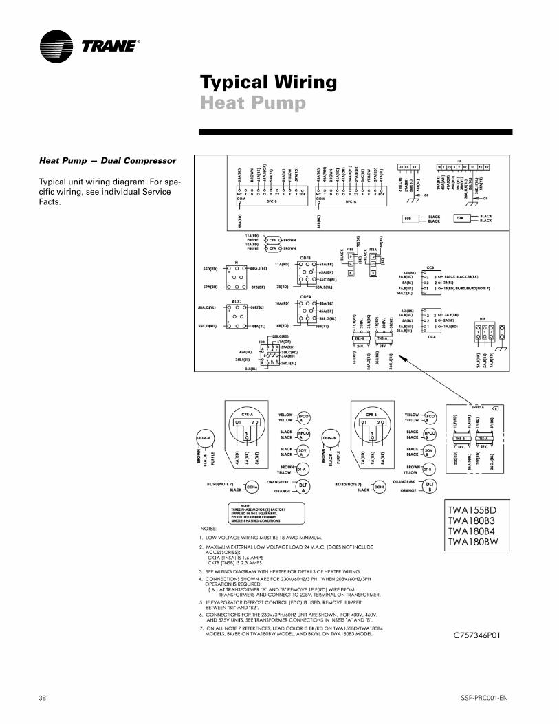
Heat Pump — Dual Compressor
Typical unit wiring diagram. For spe-cific wiring, see individual Service Facts.
Typical WiringHeat Pump
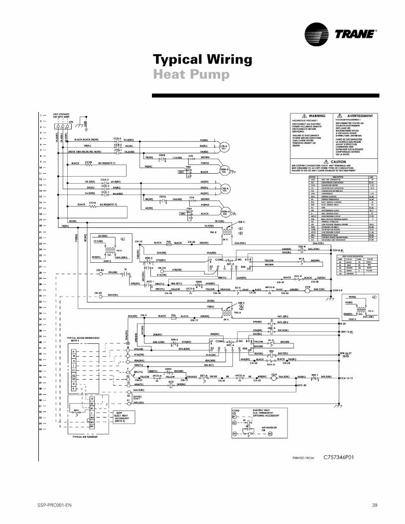
SSP-PRC001-EN 39
Typical WiringHeat Pump
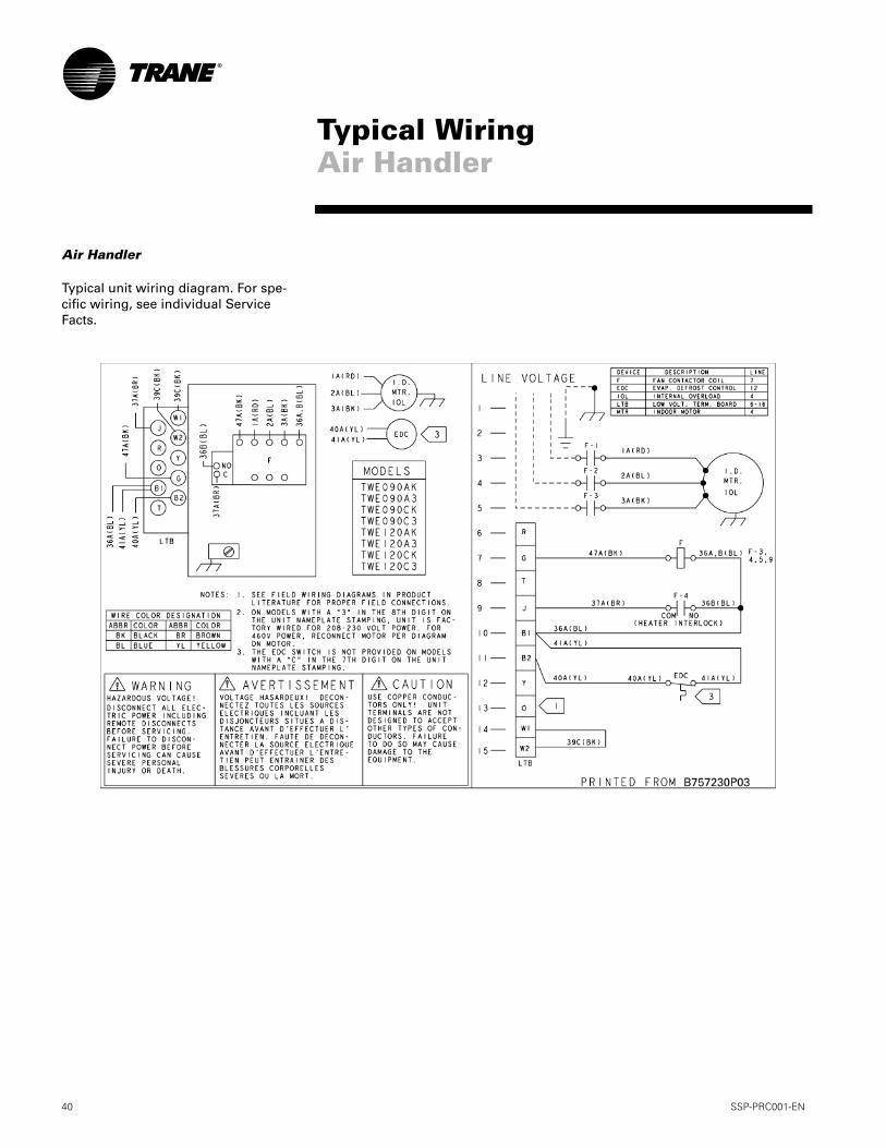
40 SSP-PRC001-EN
Air Handler
Typical unit wiring diagram. For spe-cific wiring, see individual Service Facts.
Typical WiringAir Handler
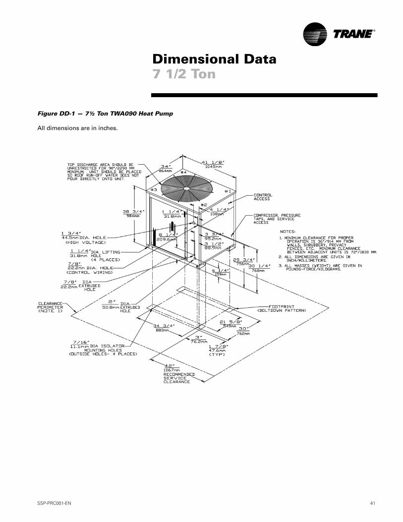
SSP-PRC001-EN 41
Figure DD-1 — 7½ Ton TWA090 Heat Pump
All dimensions are in inches.
Dimensional Data7 1/2 Ton
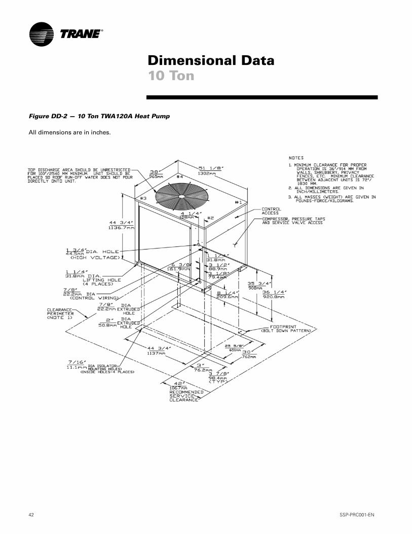
42 SSP-PRC001-EN
Figure DD-2 — 10 Ton TWA120A Heat Pump
All dimensions are in inches.
Dimensional Data10 Ton
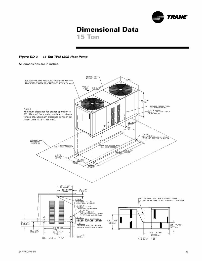
SSP-PRC001-EN 43
Figure DD-3 — 15 Ton TWA180B Heat Pump
All dimensions are in inches.
Note 1Minimum clearance for proper operation is 36" (914 mm) from walls, shrubbery, privacy fences, etc. Minimum clearance between ad-jacent units is 72" (1828 mm).
Dimensional Data15 Ton
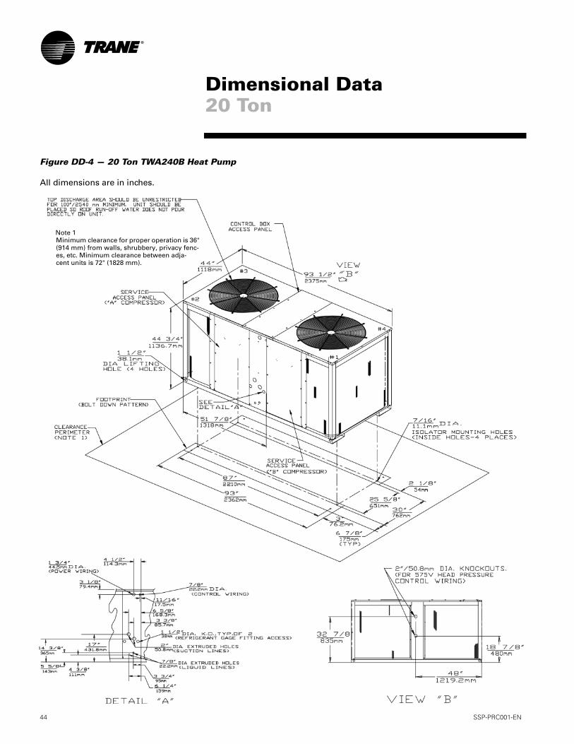
44 SSP-PRC001-EN
Figure DD-4 — 20 Ton TWA240B Heat Pump
All dimensions are in inches.
Note 1Minimum clearance for proper operation is 36" (914 mm) from walls, shrubbery, privacy fenc-es, etc. Minimum clearance between adja-cent units is 72" (1828 mm).
Dimensional Data20 Ton
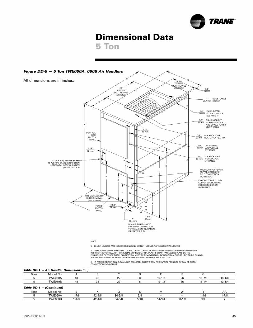
SSP-PRC001-EN 45
Figure DD-5 — 5 Ton TWE060A, 060B Air Handlers
All dimensions are in inches.
Dimensional Data5 Ton
Table DD-1 — Air Handler Dimensions (in.)
Table DD-1 — (Continued)
Tons Model No. A B C D E F G H5 TWE060A 48 38 22 8 19-1/2 26 15-7/8 14-1/85 TWE060B 48 38 22 8 19-1/2 26 16-1/4 13-1/4
Tons Model No. J K Q S V W Y AA5 TWE060A 1-7/8 42-1/8 34-5/8 3/8 — — 1-1/8 1-7/85 TWE060B 1-1/8 42-1/8 34-5/8 5/16 14-3/4 11-1/8 3/4 2
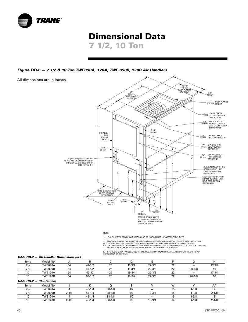
46 SSP-PRC001-EN
Figure DD-6 — 7 1/2 & 10 Ton TWE090A, 120A; TWE 090B, 120B Air Handlers
All dimensions are in inches.
Dimensional Data7 1/2, 10 Ton
Table DD-2 — Air Handler Dimensions (in.)
Table DD-2 — (Continued)
Tons Model No. A B C D E F G H7½ TWE090A 54 47-1/2 25 11-3/4 22-3/8 22 — 17-3/47½ TWE090B 54 47-1/2 25 11-3/4 22-3/8 22 20-1/8 1610 TWE120A 54 63-12 25 19-3/4 22-3/8 22 — 17-3/410 TWE120B 54 63-1/2 25 19-3/4 22-3/8 22 20-1/8 16
Tons Model No. J K Q S V W Y AA7½ TWE090A 4 45-1/4 38-1/8 1/2 — 15 1-3/8 27½ TWE090B 2-1/8 45-1/4 38-1/8 3/8 18-3/4 14 1-1/8 2-1/810 TWE120A 4 45-1/4 38-1/8 1/2 — 15 1-3/8 210 TWE120B 2-1/8 45-1/4 38-1/8 3/8 18-3/4 14 1-1/8 2-1/8
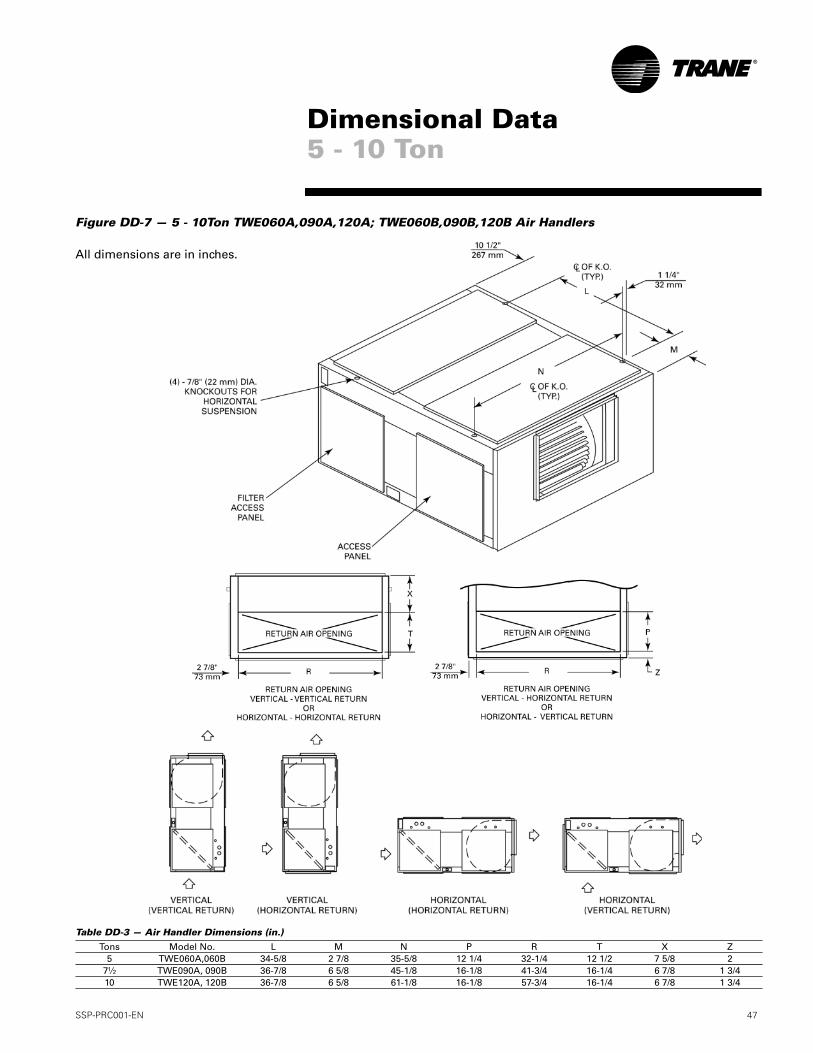
SSP-PRC001-EN 47
Figure DD-7 — 5 - 10Ton TWE060A,090A,120A; TWE060B,090B,120B Air Handlers
All dimensions are in inches.
Dimensional Data5 - 10 Ton
Table DD-3 — Air Handler Dimensions (in.)
Tons Model No. L M N P R T X Z5 TWE060A,060B 34-5/8 2 7/8 35-5/8 12 1/4 32-1/4 12 1/2 7 5/8 2
7½ TWE090A, 090B 36-7/8 6 5/8 45-1/8 16-1/8 41-3/4 16-1/4 6 7/8 1 3/410 TWE120A, 120B 36-7/8 6 5/8 61-1/8 16-1/8 57-3/4 16-1/4 6 7/8 1 3/4
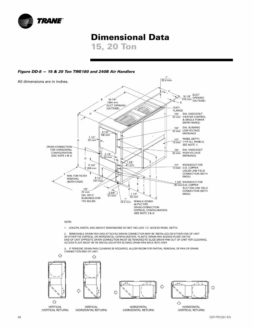
48 SSP-PRC001-EN
Figure DD-8 — 15 & 20 Ton TWE180 and 240B Air Handlers
All dimensions are in inches.
Dimensional Data15, 20 Ton
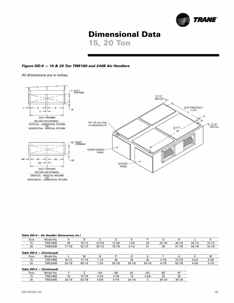
SSP-PRC001-EN 49
Figure DD-9 — 15 & 20 Ton TWE180 and 240B Air Handlers
All dimensions are in inches.
Dimensional Data15, 20 Ton
Table DD-4— Air Handler Dimensions (in.)
Table DD-4 — (Continued)
Table DD-4 — (Continued)
Tons Model No. A B C D E F G H J K15 TWE180B 69 79-1/2 27-5/8 12-3/8 1-5/8 26 25-1/8 49-1/8 56-1/4 15-1/220 TWE240B 71-7/8 92-1/2 30-1/2 18-7/8 4-1/2 31 28 51-7/8 59-1/8 18-1/8
Tons Model No. L M N P R S T U V W15 TWE180B 19-1/2 77-1/4 1 1/4 48 35 35 2-7/8 73-7/8 3-3/4 3-3/820 TWE240B 20-7/8 89-1/4 1 3/4 50-7/8 39-1/8 39-1/8 4-7/8 82-7/8 4-5/8 3-1/8
Tons Model No. Y Z AA AB AC AD AE AF15 TWE180B 18 73-7/8 3-3/4 2-7/8 18 3-5/8 35 3520 TWE240B 20-1/8 82-7/8 4-5/8 4-7/8 20-1/8 3 39-1/8 39-1/8
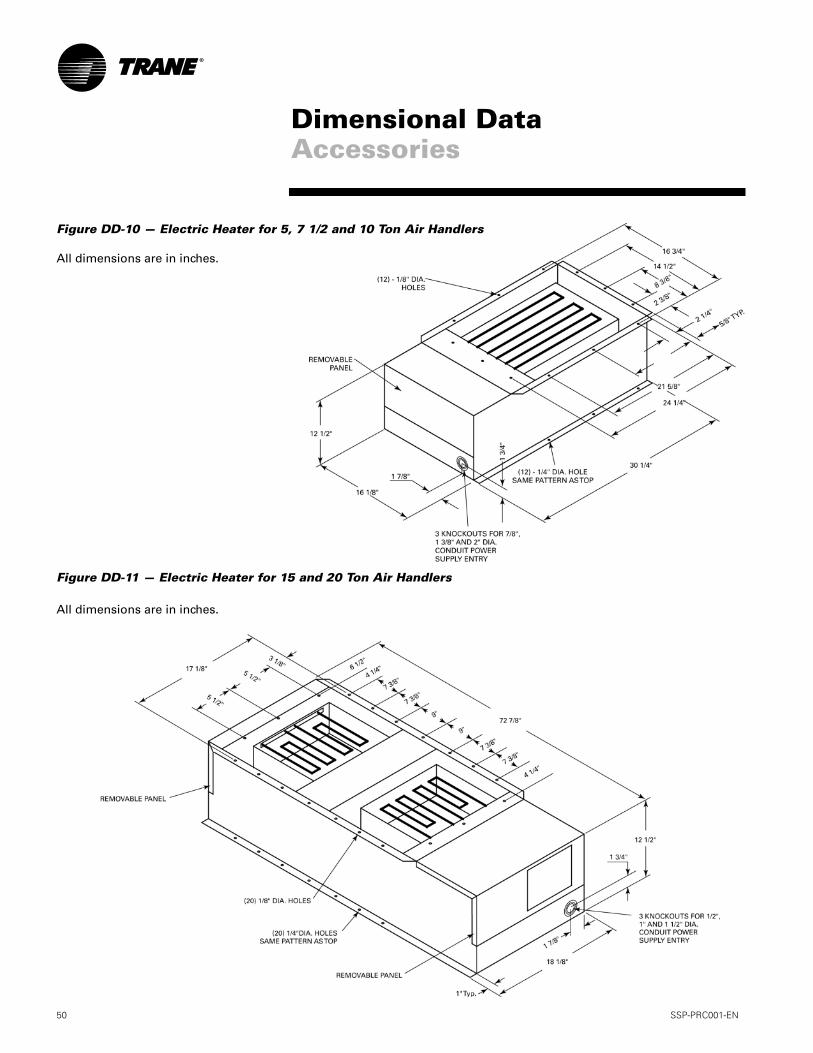
50 SSP-PRC001-EN
Figure DD-10 — Electric Heater for 5, 7 1/2 and 10 Ton Air Handlers
All dimensions are in inches.
Figure DD-11 — Electric Heater for 15 and 20 Ton Air Handlers
All dimensions are in inches.
Dimensional DataAccessories
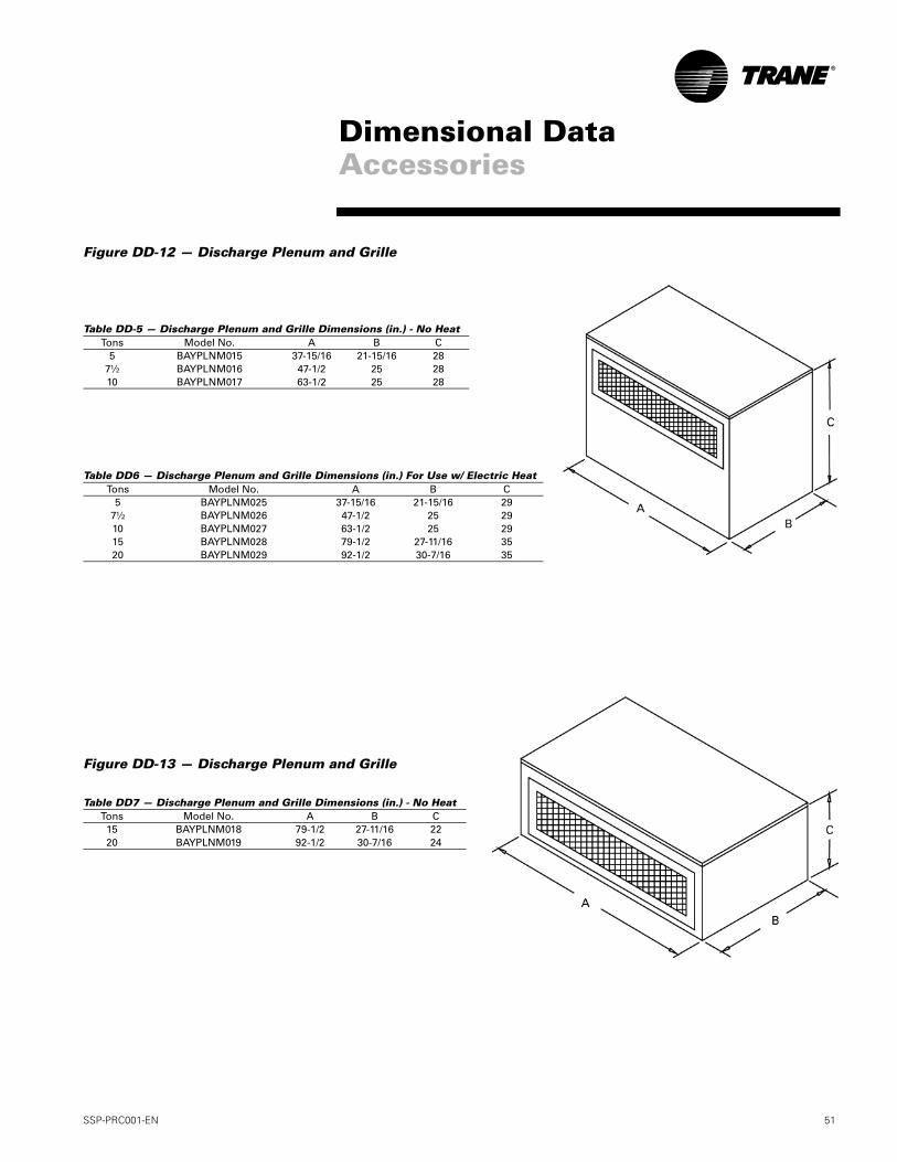
SSP-PRC001-EN 51
Figure DD-12 — Discharge Plenum and Grille
Table DD-5 — Discharge Plenum and Grille Dimensions (in.) - No Heat
Table DD6 — Discharge Plenum and Grille Dimensions (in.) For Use w/ Electric Heat
Figure DD-13 — Discharge Plenum and Grille
Table DD7 — Discharge Plenum and Grille Dimensions (in.) - No Heat
Tons Model No. A B C5 BAYPLNM015 37-15/16 21-15/16 28
7½ BAYPLNM016 47-1/2 25 2810 BAYPLNM017 63-1/2 25 28
Tons Model No. A B C5 BAYPLNM025 37-15/16 21-15/16 29
7½ BAYPLNM026 47-1/2 25 2910 BAYPLNM027 63-1/2 25 2915 BAYPLNM028 79-1/2 27-11/16 3520 BAYPLNM029 92-1/2 30-7/16 35
Tons Model No. A B C15 BAYPLNM018 79-1/2 27-11/16 2220 BAYPLNM019 92-1/2 30-7/16 24
Dimensional DataAccessories
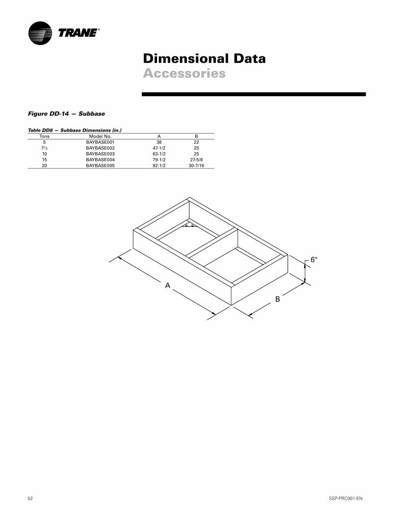
52 SSP-PRC001-EN
Figure DD-14 — Subbase
Table DD8 — Subbase Dimensions (in.)Tons Model No. A B
5 BAYBASE001 38 227½ BAYBASE002 47-1/2 2510 BAYBASE003 63-1/2 2515 BAYBASE004 79-1/2 27-5/820 BAYBASE005 92-1/2 30-7/16
Dimensional DataAccessories
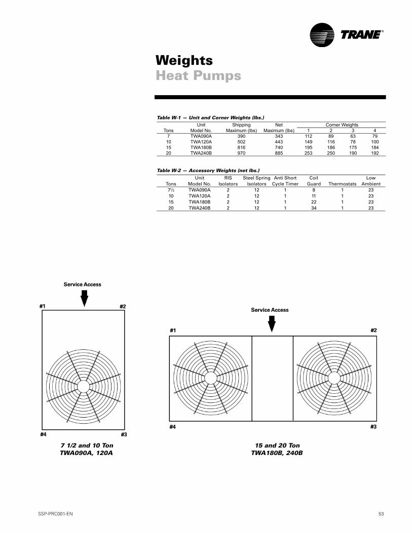
SSP-PRC001-EN 53
WeightsHeat Pumps
Table W-1 — Unit and Corner Weights (lbs.)
Table W-2 — Accessory Weights (net lbs.)
Unit Shipping Net Corner WeightsTons Model No. Maximum (lbs) Maximum (lbs) 1 2 3 4
7 TWA090A 390 343 112 89 63 7910 TWA120A 502 443 149 116 78 10015 TWA180B 816 740 195 186 175 18420 TWA240B 970 885 253 250 190 192
Unit RIS Steel Spring Anti Short Coil LowTons Model No. Isolators Isolators Cycle Timer Guard Thermostats Ambient7½ TWA090A 2 12 1 8 1 2310 TWA120A 2 12 1 11 1 2315 TWA180B 2 12 1 22 1 2320 TWA240B 2 12 1 34 1 23
15 and 20 TonTWA180B, 240B
7 1/2 and 10 TonTWA090A, 120A
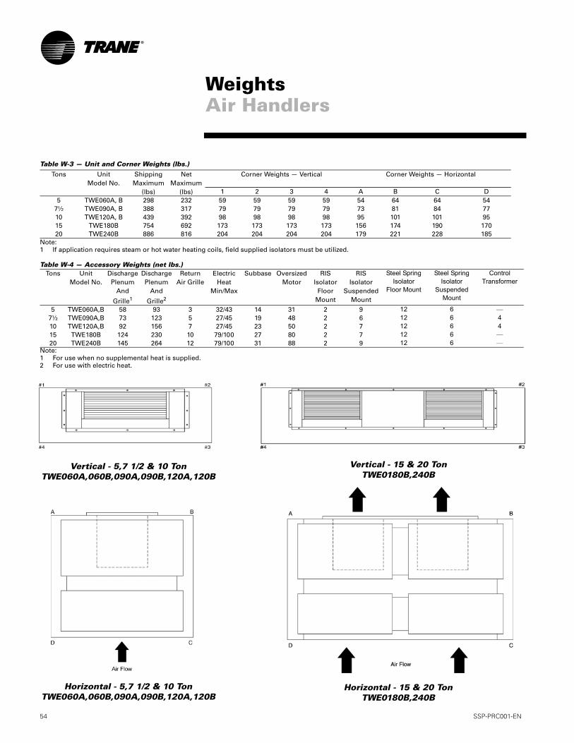
54 SSP-PRC001-EN
Table W-3 — Unit and Corner Weights (lbs.)
Note:1 If application requires steam or hot water heating coils, field supplied isolators must be utilized.
Table W-4 — Accessory Weights (net lbs.)
Note:1 For use when no supplemental heat is supplied.2 For use with electric heat.
Tons UnitModel No.
ShippingMaximum
(lbs)
NetMaximum
(lbs)
Corner Weights — Vertical
Corner Weights — Horizontal
1 2 3 4 A B C D5 TWE060A, B 298 232 59 59 59 59 54 64 64 54
7½ TWE090A, B 388 317 79 79 79 79 73 81 84 7710 TWE120A, B 439 392 98 98 98 98 95 101 101 9515 TWE180B 754 692 173 173 173 173 156 174 190 17020 TWE240B 886 816 204 204 204 204 179 221 228 185
Tons UnitModel No.
DischargePlenum
And
Grille1
DischargePlenum
And
Grille2
ReturnAir Grille
ElectricHeat
Min/Max
Subbase OversizedMotor
RISIsolator
Floor Mount
RISIsolator
SuspendedMount
Steel SpringIsolator
Floor Mount
Steel SpringIsolator
SuspendedMount
ControlTransformer
5 TWE060A,B 58 93 3 32/43 14 31 2 9 12 6 —7½ TWE090A,B 73 123 5 27/45 19 48 2 6 12 6 410 TWE120A,B 92 156 7 27/45 23 50 2 7 12 6 415 TWE180B 124 230 10 79/100 27 80 2 7 12 6 —20 TWE240B 145 264 12 79/100 31 88 2 9 12 6 —
WeightsAir Handlers
Vertical - 5,7 1/2 & 10 TonTWE060A,060B,090A,090B,120A,120B
Vertical - 15 & 20 TonTWE0180B,240B
Horizontal - 5,7 1/2 & 10 TonTWE060A,060B,090A,090B,120A,120B
Horizontal - 15 & 20 TonTWE0180B,240B

SSP-PRC001-EN 55
Heat PumpsGeneralUnits shall be assembled on heavy gauge steel mounting/lifting rails and shall be weather proofed. Unit shall include a hermetic scroll or reciprocat-ing compressor(s), plate fin con-denser coil, fans and motors, controls and holding charge of nitrogen. Oper-ating Range shall be between 115° F to 50° F in cooling as standard from fac-tory. Units shall be UL 1995 listed and rated in accordance with ARI Standard 340/360.
CasingUnit casing shall be constructed of 18 gauge zinc coated heavy gauge, gal-vanized steel. Exterior surfaces shall be cleaned, phosphatized and finished with a weather-resistant baked enamel finish. Units surface shall be tested 500 hours in salt spray test. Units shall have removable end pan-els which allow access to all major components and controls.
Refrigeration System — Single CompressorTWA090A, TWA120A units shall have a single refrigeration circuit. Each refrigeration circuit has an integral subcooling circuit. A refrigeration fil-ter drier, expansion valve and check valves shall be provided as standard. The TWA090A, TWA120A units shall have both a liquid line and suction gas line service valve with gauge port. TWA090A, TWA120A units shall have one direct drive Trane hermetic scroll compressor with centrifugal oil pump providing positive lubrication to mov-ing parts. Motor shall be suction gas-cooled and shall have a voltage utili-zation range of plus or minus 10 per-cent of nameplate voltage. Crankcase heater, internal temperature and cur-rent-sensitive motor overloads shall be included for maximum protection. Scroll type compressor shall provide inherently low vibration and noise by having no suction and discharge valves. External high and low pres-
sure cutout devices shall be provided. Evaporator defrost control provided in indoor blower coil unit shall prevent compressor slugging by temporarily interrupting compressor operation when low evaporator coil tempera-tures are encountered.
Refrigeration System — Dual CompressorTWA180B, TWA240B units shall have two separate and independent refrig-eration circuits. Each refrigeration cir-cuit shall have an integral subcooling circuit. A refrigeration filter drier shall be provided as standard. Units shall have both a liquid line and suction gas line service valve with gauge ports. TWA180B, TWA240B units shall have two Trane direct drive hermetic scroll compressors with centrifugal oil pump and provide positive lubrication to all moving parts. Motor shall be suction gas-cooled and shall have a voltage utilization range of plus or minus 10 percent of nameplate volt-age. Crankcase heater, internal tem-perature and current-sensitive motor overloads shall be included for maxi-mum protection. Scroll type compres-sor shall provide inherently low vibration and noise by having no suc-tion and discharge valves. External high and low pressure cutout devices shall be provided. Evaporator defrost control provided in indoor blower coil shall prevent compressor slugging by temporarily interrupting compressor operation when low evaporator coil temperatures are encountered.
Condenser CoilCoils shall be internally finned or smooth bore 3/8" copper tubes mechanically bonded to configured aluminum plate fin as standard. Coil shall be factory pressure and leak tested to 420 psig air pressure. Metal grilles with PVC coating for coil pro-tection is optional.
Condenser Fan and Motor(s) Direct-drive, statically and dynami-cally balanced 26 or 28 inch propeller fan(s) with aluminum blades and elec-tro-coated steel hubs shall be used in draw-through vertical discharge posi-tion. Either permanently lubricated totally enclosed or open construction type motors shall be provided and shall have built in current and thermal overload protection. Motor(s) shall have either ball or sleeve bearing type.
ControlsHeat pump units shall be completely factory wired with necessary controls and contactor pressure lugs or termi-nal block for power wiring. Control wiring shall be 24-volt control circuit which includes fusing and control transformer. Units shall provide exter-nal location for mounting a fused dis-connect device. Time delay timers to prevent compressors in dual com-pressor units from simultaneous start-up and anti-recycle timers are avail-able as optional accessories.
Defrost Controls Electronic timed initiated, tempera-ture terminated defrost system with choice of 50, 70, or 90 minute cycle. Timed override limits defrost cycle to 10 minutes.
Low Ambient Operation Standard units shall start and operate to approximately 50° F when matched with Trane air handlers and coils. Optional head pressure control acces-sory permits operation to 0° F.
MechanicalSpecifications
56 SSP-PRC001-EN
Accessories
Low Ambient Head Pressure Con-trol — Shall modulate the RPM of unit outdoor fan motor in response to out-door ambient temperatures and liquid line temperature. Accessory provides unit cooling operation to outdoor tem-peratures of 0° F.
Vibration Isolation Packages — Shall reduce transmission of noise and vibration to building structures, equipment and adjacent spaces. Pack-ages shall be available in either neo-prene-in-shear or spring-flex types.
Time Delay Relay — Shall prevent compressors in dual compressor unit from coming on line simultaneously. Timer shall be 24-volt, 60 cycle, with four minute timing period.
Anti-Short-Cycle Timer — Shall pre-vent rapid on-off compressor cycling in light load conditions by not allowing compressor to operate for 5-7 minutes upon shutdown. Shall consist of a sol-id state timing device, 24-volt, 60 cycle with either 5 or 7 minute fixed-off tim-ing period.
Condenser Coil Guard — Metal grille with PVC coating shall be pro-vided to alleviate coil damage.
Black Epoxy Coated Condenser Coil — The black epoxy coils have a thermoset vinyl coating that is bonded to the aluminum fin stock prior to the fin-stamping process. The pre-coated coils are an economical option for protection in mildly corro-sive environments.
Air HandlersGeneralAir handler units shall be completely factory assembled including coil, con-densate drain pan, fan motor(s), filters and controls in an insulated casing that can be applied in either vertical or horizontal configuration. Units shall be rated and tested in accordance with ARI standard 340/360. Units shall be UL listed and labeled in accor-dance with UL 1995 for indoor blower coil units.
CasingUnit casing shall be constructed of zinc coated, heavy gauge, galvanized steel. Exterior surfaces shall be cleaned, phosphatized and finished with a weather-resistant baked enamel finish. Casing shall be com-pletely insulated with cleanable, foil faced, fire-retardant, permanent, odorless glass fiber material. All insu-lation edges shall be either captured or sealed. Knockouts shall be pro-vided for unit electrical power and refrigerant piping connections. Cap-tive screws shall be standard on all access panels.
Refrigeration SystemThe TWE060A, TWE090A, TWE120A units shall have a single refrigeration circuit and the TWE060B, TWE090B, TWE120B, TWE180B, TWE240B units shall have dual refrigeration circuits. Each refrigeration circuit is controlled by a factory installed thermal expan-sion valve.
Evaporator CoilConfigured aluminum fin surface shall be mechanically bonded to 3/8" inter-nally enhanced copper tubing and fac-tory pressure and leak tested at 375 psig. Coil is arranged for draw-through airflow and shall provide a double sloped condensate drain pan constructed of PVC plastic. The drain pan shall be removable for cleaning. The condensate drain pan can be installed in any of four positions allowing for vertical or horizontal application and providing external connections on either side of the unit.
Evaporator FanDouble inlet, double width, forward curved, centrifugal-type fan(s) with adjustable belt drive shall be stan-dard. Thermal overload protection shall be standard on motor. Fan and motor bearings shall be permanently lubricated. Oversized motors shall be available as an option for high static application. All indoor fan motors meet the U.S. Energy Policy Act of 1992 (EPACT)
ControlsMagnetic evaporator fan contactor, low voltage terminal strip, check valve(s), and single point power entry shall be included. All necessary con-trols shall be factory-installed and wired. Evaporator defrost control shall be included to prevent compres-sor slugging by temporarily interrupt-ing compressor operation when low evaporator coil temperatures are encountered.
MechanicalSpecifications
SSP-PRC001-EN 57
FiltersOne inch, throw-away filters shall be standard on TWE060A, TWE090A, TWE060B, TWE090B and TWE120B model air handlers. Filters shall be ac-cessible from the side coil access pan-el. Filter rack can be field converted to two inch capability. Two inch, throw-away filters shall be standard on TWE180B and TWE240B models.
Accessories
Electric Heaters — UL and CSA ap-proved electric heat modules shall be available for installation directly on fan discharge. Electric Heaters shall be available in a wide range of capacities with one or two stage control, single-point electric power connection and terminal strip connections. Electric heater elements shall be constructed of heavy-duty nickel chromium ele-ments internally wye connected on 480/600 volt, three phase and delta connected on 208/240 volt, three phase. Each 208/240 volt heater shall have pilot duty with secondary backup fuse links for automatic reset of high limit controls. Each 480/600 volt heater shall have automatic line break high limit controls.
Discharge Plenums and Grilles —Accessory discharge plenums shall be available for vertical, free discharge applications. Plenums shall be con-structed of heavy-gauge, zinc coated galvanized steel finished with baked enamel to match the air handler unit. Grilles shall be satin finished alumi-num and have four-way adjustable louvers.
Return Air Grilles — Accessory re-turn air grille shall be provided for ver-tical front, free return applications. Grilles shall be installed in place of the front lower side panel. Grille shall be satin finished aluminum with non-ad-justable louvers.
Mounting Subbase — Available for vertical floor mount configurations. Subbase shall be constructed of heavy gauge, zinc coated galvanized steel
with baked enamel finish to match air handler unit. Subbase is required in the vertical air flow application for condensate drain trapping and when isolators are required.
Vibration Isolators — Shall reduce transmission of noise and vibration to building structures, equipment and adjacent spaces. Packages shall be available in either neoprene-in shear or spring-flex types in floor or sus-pended mountings.
Oversized Motors — Field installed oversized motors shall be available for high static pressure applications.
Control Options
Standard Indoor Thermostats — Two stage heating and cooling opera-tion or one stage heating and cooling thermostats shall be available in either manual or automatic changeover.
Programmable Electronic Night Setback Thermostat — Shall pro-vide heating setback and cooling setup with 7-day programming capability.
Outdoor Thermostat — Shall pro-vide staging control of electric heaters based on a set outdoor temperature.
MechanicalSpecifications


Trane has a policy of continuous product and data improvement and reserves the right to change design and specifications without notice.
Literature Order Number SSP-PRC001-EN
File Number PL-UN-000-SSP-PRC001-EN-0805
Supersedes PL-UN-000-SSP-PRC001-0205
Stocking Location Webb/MasonTrane A business of American Standard Companieswww.trane.com
For more information, contact your local district office or e-mail us at [email protected]