Embed Size (px)
Citation preview

EDUS281008
Split System Air ConditionersAir Handling Unit
FTQ-PA + RZQ-P9
EDUS281008
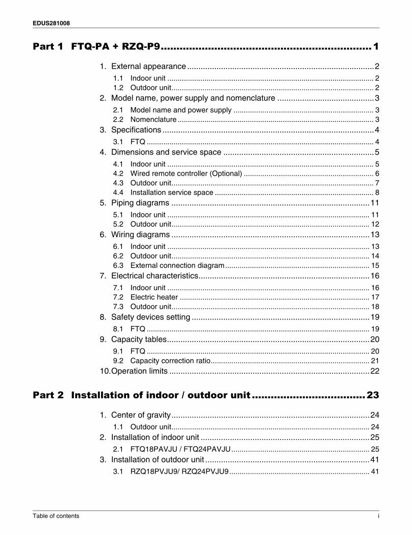
Part 1 FTQ-PA + RZQ-P9...................................................................1
1. External appearance ...................................................................................21.1 Indoor unit .................................................................................................... 21.2 Outdoor unit.................................................................................................. 2
2. Model name, power supply and nomenclature ...........................................3
2.1 Model name and power supply .................................................................... 32.2 Nomenclature ............................................................................................... 3
3. Specifications ..............................................................................................4
3.1 FTQ .............................................................................................................. 44. Dimensions and service space ...................................................................5
4.1 Indoor unit .................................................................................................... 54.2 Wired remote controller (Optional) ............................................................... 64.3 Outdoor unit.................................................................................................. 74.4 Installation service space ............................................................................. 8
5. Piping diagrams ........................................................................................11
5.1 Indoor unit .................................................................................................. 115.2 Outdoor unit................................................................................................ 12
6. Wiring diagrams ........................................................................................136.1 Indoor unit .................................................................................................. 136.2 Outdoor unit................................................................................................ 146.3 External connection diagram...................................................................... 15
7. Electrical characteristics............................................................................16
7.1 Indoor unit .................................................................................................. 167.2 Electric heater ............................................................................................ 177.3 Outdoor unit................................................................................................ 18
8. Safety devices setting ...............................................................................198.1 FTQ ............................................................................................................ 19
9. Capacity tables..........................................................................................209.1 FTQ ............................................................................................................ 209.2 Capacity correction ratio............................................................................. 21
10.Operation limits .........................................................................................22
Part 2 Installation of indoor / outdoor unit ....................................23
1. Center of gravity........................................................................................241.1 Outdoor unit................................................................................................ 24
2. Installation of indoor unit ...........................................................................252.1 FTQ18PAVJU / FTQ24PAVJU................................................................... 25
3. Installation of outdoor unit .........................................................................413.1 RZQ18PVJU9/ RZQ24PVJU9.................................................................... 41
Table of contents i
EDUS281008
Part 3 Detail information of options ..............................................59
1. Accessories...............................................................................................601.1 Indoor unit .................................................................................................. 601.2 Outdoor unit................................................................................................ 60
2. RZQ...........................................................................................................61
2.1 KKPJ5F180 — Central drain plug .............................................................. 612.2 K-KYZP15C — Wire fixture for preventing overturning .............................. 632.3 KPT-60B160 — Fixture for preventing overturning .................................... 65
ii Table of contents
EDUS281008
FTQ-PA + RZQ-P 1
1
Part 1
FTQ-PA + RZQ-P91. External appearance ...................................................................................2
1.1 Indoor unit .................................................................................................... 21.2 Outdoor unit.................................................................................................. 2
2. Model name, power supply and nomenclature ...........................................32.1 Model name and power supply .................................................................... 32.2 Nomenclature ............................................................................................... 3
3. Specifications ..............................................................................................43.1 FTQ .............................................................................................................. 4
4. Dimensions and service space ...................................................................54.1 Indoor unit .................................................................................................... 54.2 Wired remote controller (Optional) ............................................................... 64.3 Outdoor unit.................................................................................................. 74.4 Installation service space ............................................................................. 8
5. Piping diagrams ........................................................................................115.1 Indoor unit .................................................................................................. 115.2 Outdoor unit................................................................................................ 12
6. Wiring diagrams ........................................................................................136.1 Indoor unit .................................................................................................. 136.2 Outdoor unit................................................................................................ 146.3 External connection diagram...................................................................... 15
7. Electrical characteristics............................................................................167.1 Indoor unit .................................................................................................. 167.2 Electric heater ............................................................................................ 177.3 Outdoor unit................................................................................................ 18
8. Safety devices setting ...............................................................................198.1 FTQ ............................................................................................................ 19
9. Capacity tables..........................................................................................209.1 FTQ ............................................................................................................ 209.2 Capacity correction ratio............................................................................. 21
10.Operation limits .........................................................................................22
External appearance EDUS281008
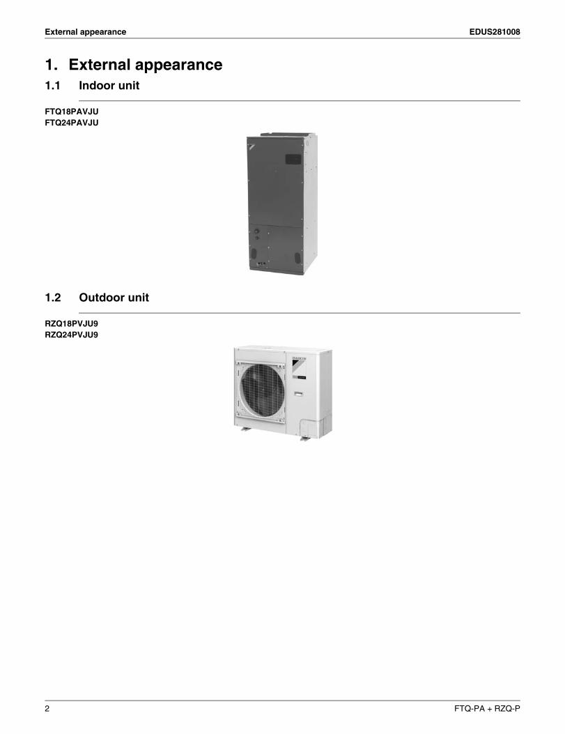
1. External appearance1.1 Indoor unit
FTQ18PAVJUFTQ24PAVJU
1.2 Outdoor unit
RZQ18PVJU9RZQ24PVJU9
2 FTQ-PA + RZQ-P
EDUS281008 Model name, power supply and nomenclature
1
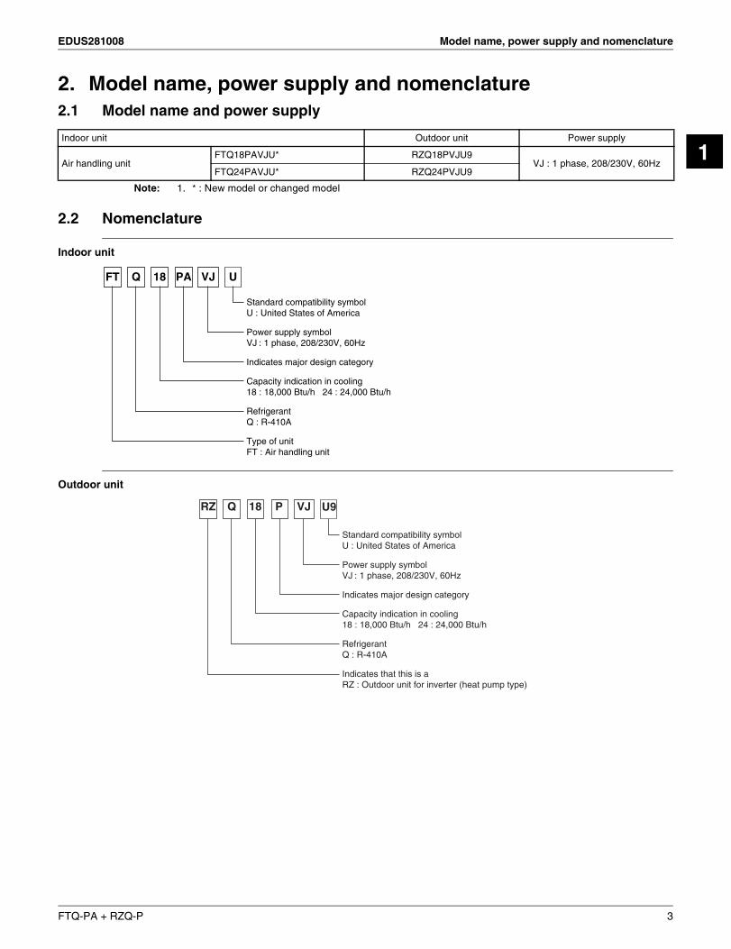
2. Model name, power supply and nomenclature2.1 Model name and power supply
Note: 1. * : New model or changed model
2.2 Nomenclature
Indoor unit
Outdoor unit
Indoor unit Outdoor unit Power supply
Air handling unitFTQ18PAVJU* RZQ18PVJU9
VJ : 1 phase, 208/230V, 60HzFTQ24PAVJU* RZQ24PVJU9
FT 18 VJPA UQ
Standard compatibility symbolU : United States of America
Power supply symbolVJ : 1 phase, 208/230V, 60Hz
Indicates major design category
Capacity indication in cooling18 : 18,000 Btu/h 24 : 24,000 Btu/h
RefrigerantQ : R-410A
Type of unitFT : Air handling unit
RZ 18 VJP U9Q
Standard compatibility symbolU : United States of America
Power supply symbolVJ : 1 phase, 208/230V, 60Hz
Indicates major design category
Capacity indication in cooling18 : 18,000 Btu/h 24 : 24,000 Btu/h
RefrigerantQ : R-410A
Indicates that this is a RZ : Outdoor unit for inverter (heat pump type)
FTQ-PA + RZQ-P 3

Specifications EDUS281008
3. Specifications3.1 FTQ
Air handling unit
Notes:1. Nominal cooling capacities are based on the following conditions:
Return air temperature : 80°FDB (27°CDB), 67°FWB (19.4°CWB)Outdoor temperature : 95°FDB (35°CDB)Equivalent ref. piping : 25ft (7.5 m) (Horizontal)
2. Nominal heating capacities are based on the following conditions:Return air temperature : 70°FDB (21°CDB)Outdoor temperature : 47°FDB (8.3°CDB), 43°FWB(6°CWB)Equivalent ref. piping : 25ft (7.5 m) (Horizontal)
(*1 and 2 are teh performance for vertical installation. For horizontal installation, capacity could decrease by about 10%)3. Capacities are net, including a deduction for cooling (an addition for heating) for indoor fan motor heat.4. Air filter is not standard accessory, but please mount it in the duct system of the suction side.5. The second drain pan (sub drain pan) must be needed as field supply parts. A secondary field-supplied drain pan may be required.
ModelIndoor unit FTQ18PAVJU FTQ24PAVJU
Outdoor unit RZQ18PVJU9 RZQ24PVJU9
Power Supply 1 phase, 208V/230V, 60Hz3 Cooling capacity Btu/h 18,000 24,0003 Heating capacity Btu/h 20,000 27,000
Indoor unit FTQ18PAVJU FTQ24PAVJU
Dimensions H×W×D in. (mm) 53–1/4 × 22 × 24 (1353 x 559 x 610)
CoilType Cross fin coilRow×Stages×FPI 8 × 22 × 15Face area ft2 (m2) 6.02 (1.8)
Fan
Model ECM (3/4 HP)Type Sirocco fanMotor output HP 3/4Airflow rate (H/L) CFM 600/420 800/560External static pressure in.H2O Up to 0.5 in. W.C.Drive Direct drive
Temperature control Microprocessor thermostat for cooling and heatingAir filter —4Weight Lbs (kg) 169 (77)
Piping Connections
Liquid in. (mm) φ3/8 (9.5) (Brazed)Gas in. (mm) φ5/8(15.8) (Brazed)Drain in. (mm) φ3/4 (19.1) 5
Outdoor unit RZQ18PVJU RZQ24PVJU
color IvoryDimensions H×W×D in. (mm) 30–5/16 × 35–7/16 × 12–5/8 (762 x 900 x 321)
CoilType Cross fin coilRow×Stages×FPI 2 × 34 × 18Face area ft2 (m)2 7.1 (2.2)
Comp.Model 2YC63HXD#EDType Hermetically sealed swing typeMotor output kW 1.7
Fan
Model P47N11FType Propeller fanMotor output W 70Airflow rate CFM 1,835
Weight Lbs (kg) 150
Piping Connections
Liquid in. (mm) φ3/8 (9.5) (Flare connection)Gas in. (mm) φ5/8 (15.8)(Flare connection)Drain in. (mm) φ1 (25.4) (Hole)
Safety devices Indoor fan driver overload protector. Fuse. High pressure switch. Outdoor fan driver overload protector. Inverter overload protector. Fusible plugs.
Capacity step % 35-100 30-100Refrigerant control Electronic expansion valve
Ref. pipingStandard length ft (m) 25 (7.5)Max. length ft (m) 98 (30)Max. height difference ft (m) 98 (30)
RefrigerantModel R-410ACharge Lbs (kg) 5.1(2.3)
Ref. oilModel Refer to the name plate of compressor.Charge Lbs (kg) 0.75 (0.34)
Drawing No. C: 4D068242
4 FTQ-PA + RZQ-P
EDUS281008 Dimensions and service space
1
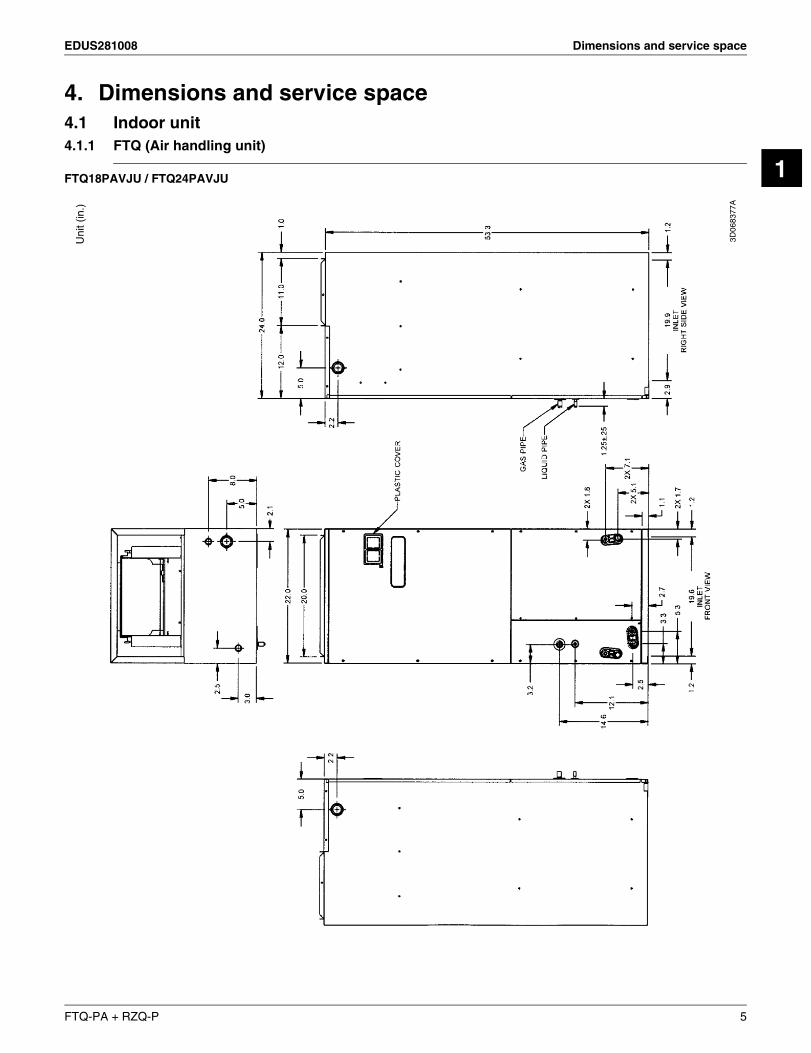
4. Dimensions and service space4.1 Indoor unit4.1.1 FTQ (Air handling unit)
FTQ18PAVJU / FTQ24PAVJU
3D06
8377
A
Uni
t (in
.)
FTQ-PA + RZQ-P 5
Dimensions and service space EDUS281008
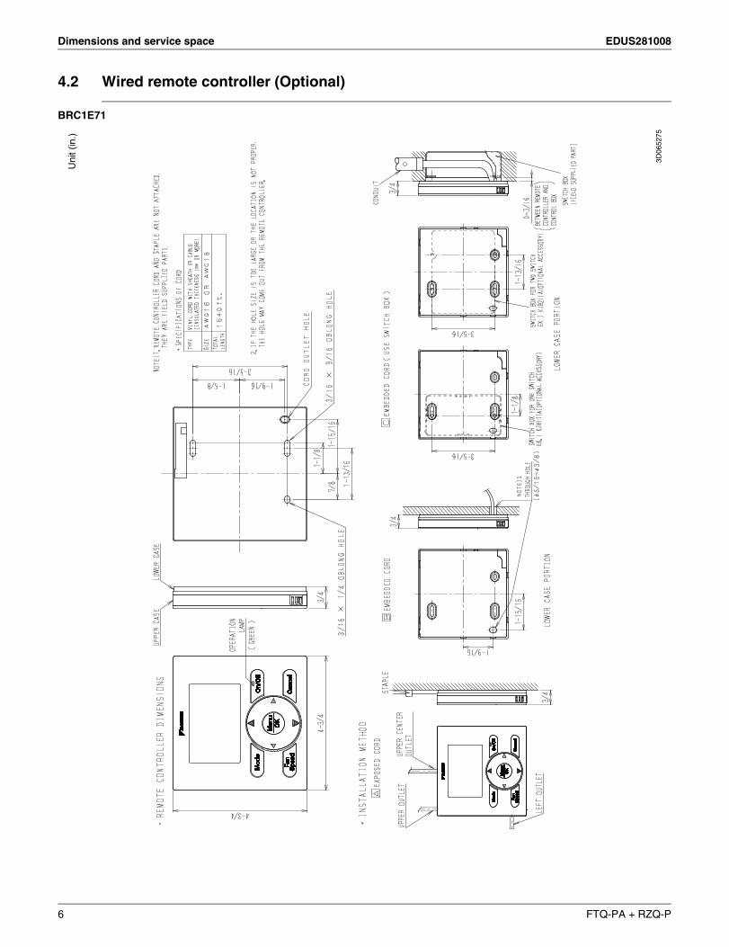
4.2 Wired remote controller (Optional)
BRC1E71
Uni
t (in
.)
3D06
5275
6 FTQ-PA + RZQ-P
EDUS281008 Dimensions and service space
1
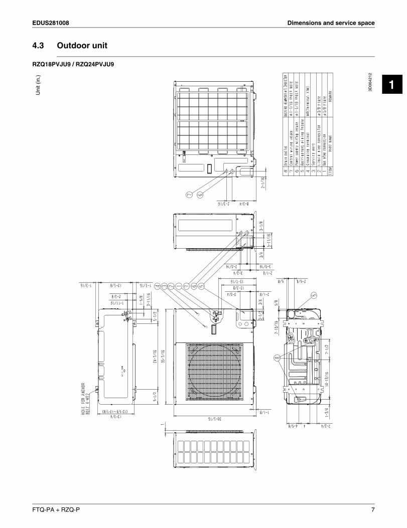
4.3 Outdoor unit
RZQ18PVJU9 / RZQ24PVJU9
3D06
4212
Uni
t (in
.)
FTQ-PA + RZQ-P 7
Dimensions and service space EDUS281008
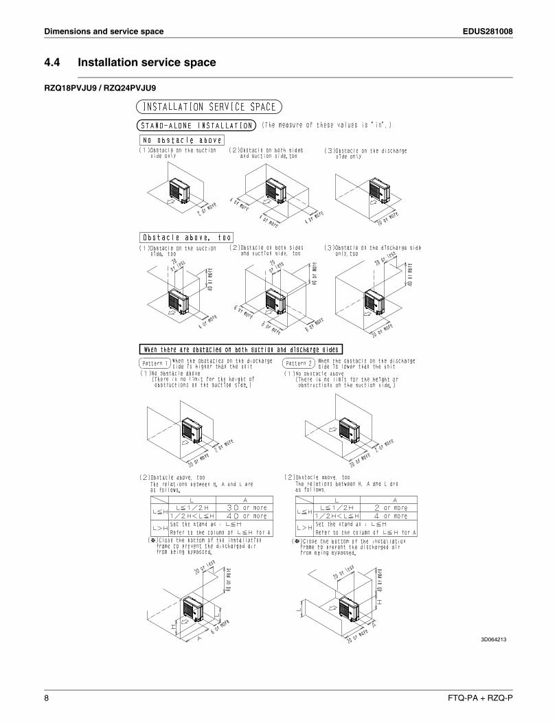
4.4 Installation service space
RZQ18PVJU9 / RZQ24PVJU9
3D064213
8 FTQ-PA + RZQ-P
EDUS281008 Dimensions and service space
1
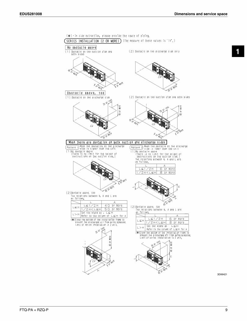
3D06421
FTQ-PA + RZQ-P 9
Dimensions and service space EDUS281008
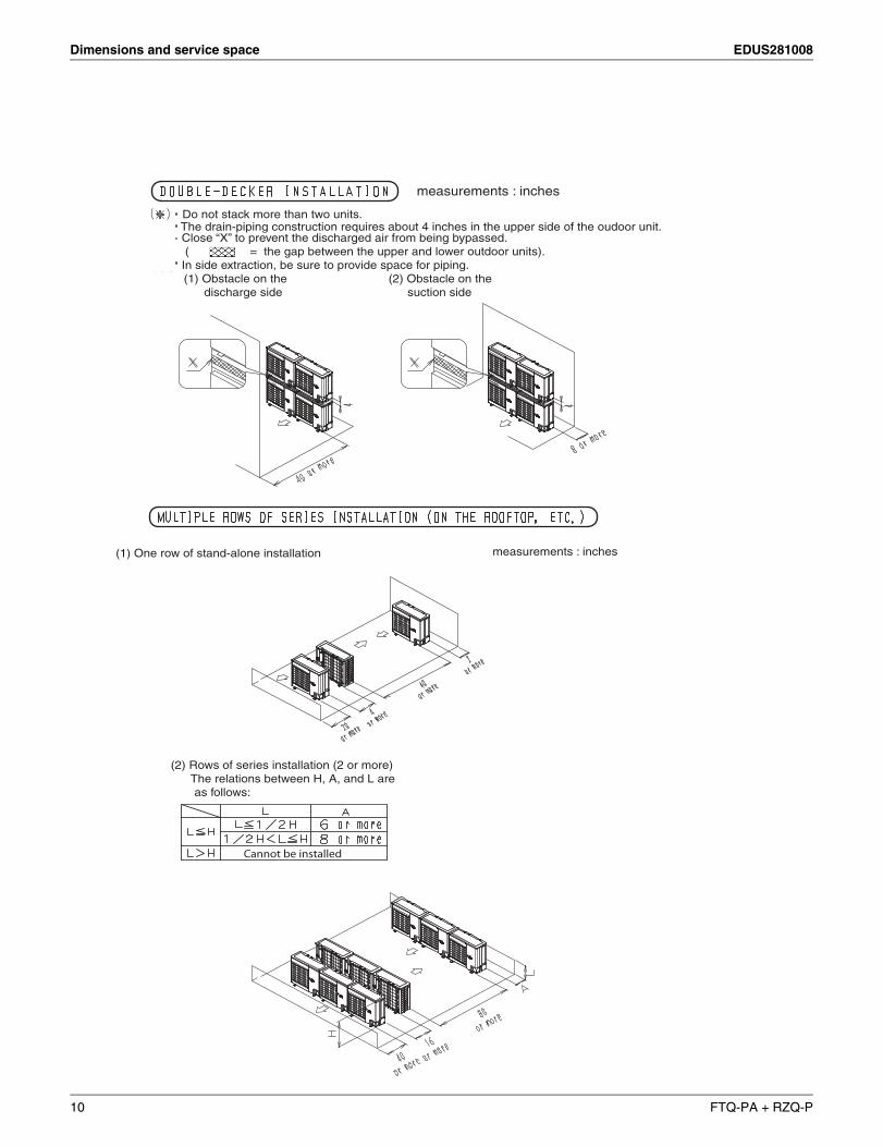
measurements : inches
measurements : inches
Do not stack more than two units.The drain-piping construction requires about 4 inches in the upper side of the oudoor unit.
(1) One row of stand-alone installation
(2) Rows of series installation (2 or more) The relations between H, A, and L are as follows:
Close “X” to prevent the discharged air from being bypassed. ( = the gap between the upper and lower outdoor units).In side extraction, be sure to provide space for piping. (1) Obstacle on the (2) Obstacle on the discharge side suction side
Cannot be installed
10 FTQ-PA + RZQ-P
EDUS281008 Piping diagrams
1
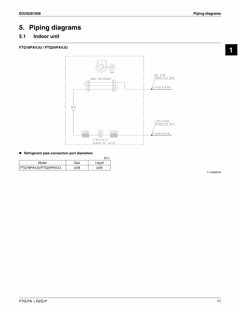
5. Piping diagrams5.1 Indoor unit
FTQ18PAVJU / FTQ24PAVJU
Refrigerant pipe connection port diameters
C: 4D068194
(in.)
Model Gas Liquid
FTQ18PAVJU/FTQ24PAVJU φ5/8 φ3/8
FTQ-PA + RZQ-P 11
Piping diagrams EDUS281008
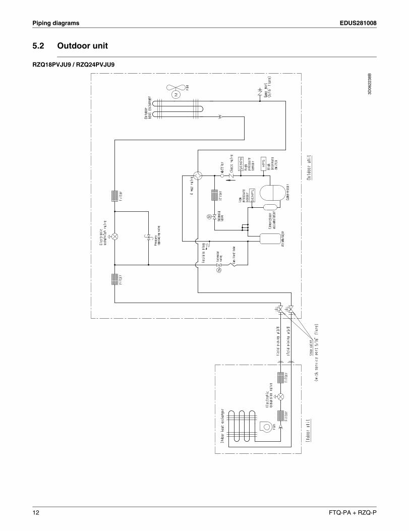
5.2 Outdoor unit
RZQ18PVJU9 / RZQ24PVJU9
3D06
2238
B
12 FTQ-PA + RZQ-P
EDUS281008 Wiring diagrams
1
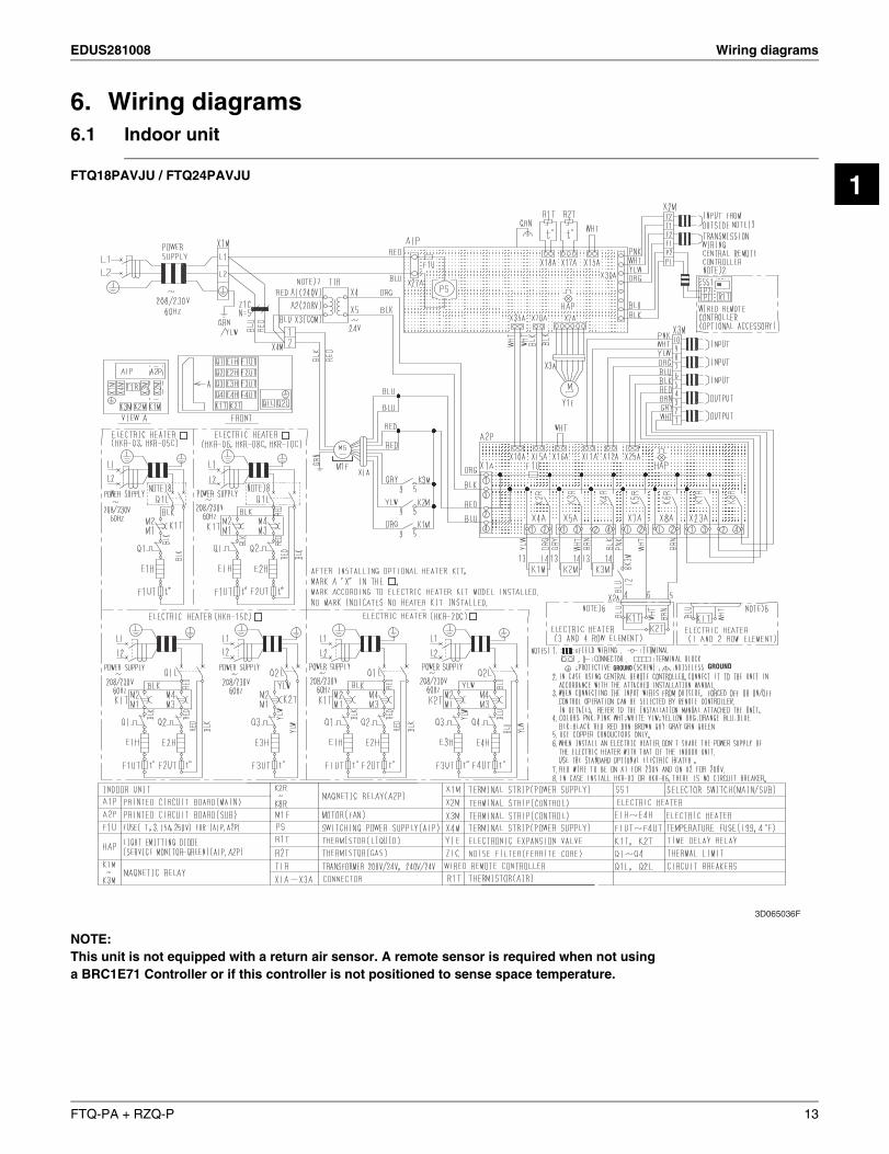
6. Wiring diagrams6.1 Indoor unit
FTQ18PAVJU / FTQ24PAVJU
NOTE: This unit is not equipped with a return air sensor. A remote sensor is required when not using a BRC1E71 Controller or if this controller is not positioned to sense space temperature.
3D065036F
GROUND GROUND
FTQ-PA + RZQ-P 13
Wiring diagrams EDUS281008
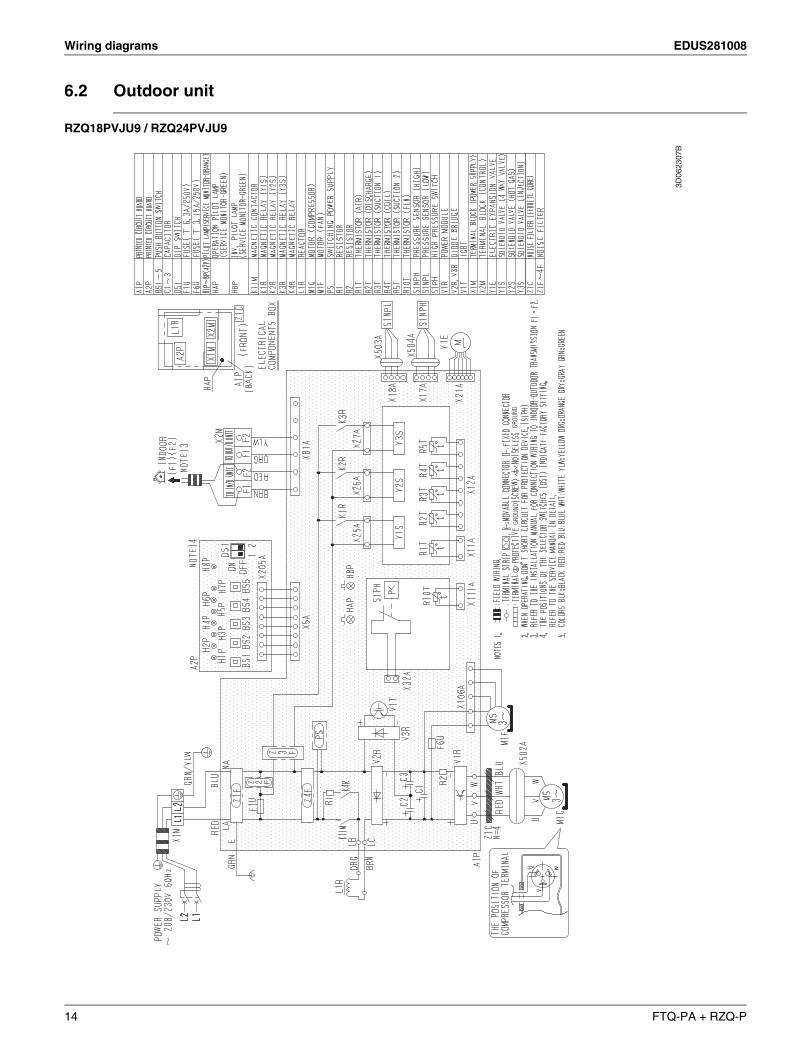
6.2 Outdoor unit
RZQ18PVJU9 / RZQ24PVJU9
3D06
2307
B
GROU
NDGR
OUND
14 FTQ-PA + RZQ-P
EDUS281008 Wiring diagrams
1
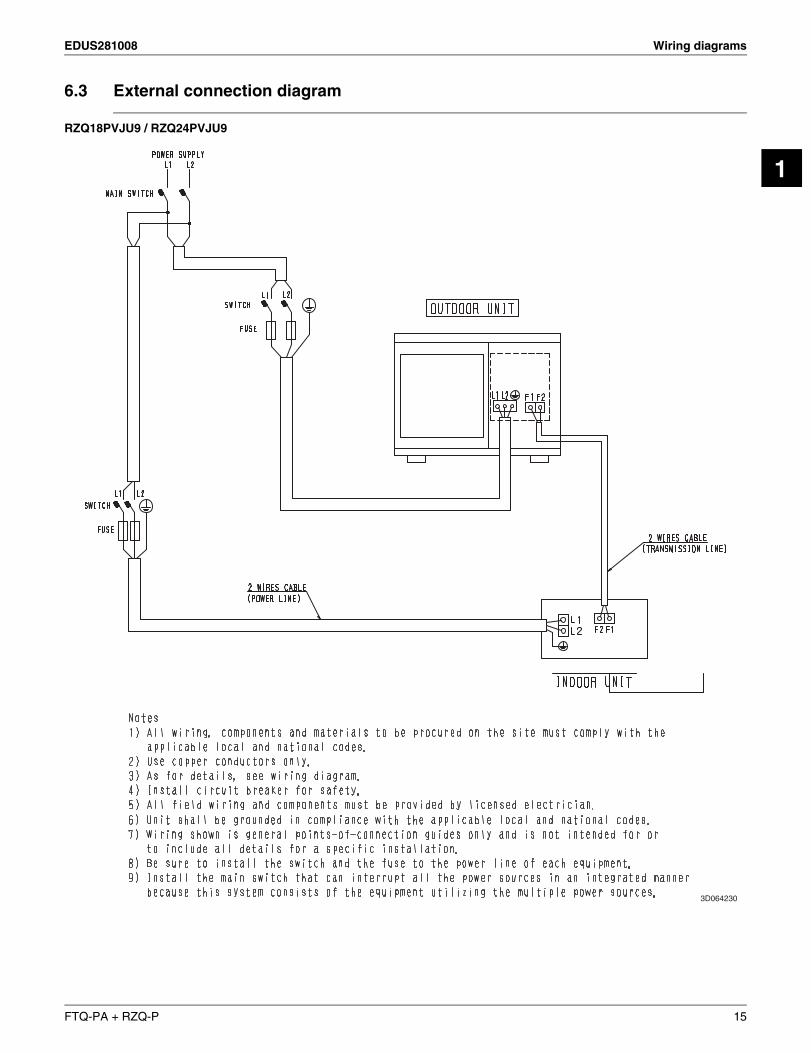
6.3 External connection diagram
RZQ18PVJU9 / RZQ24PVJU9
3D064230
FTQ-PA + RZQ-P 15
Electrical characteristics EDUS281008
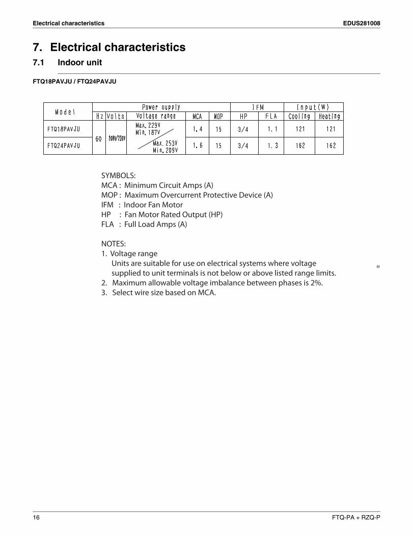
7. Electrical characteristics7.1 Indoor unit
FTQ18PAVJU / FTQ24PAVJU
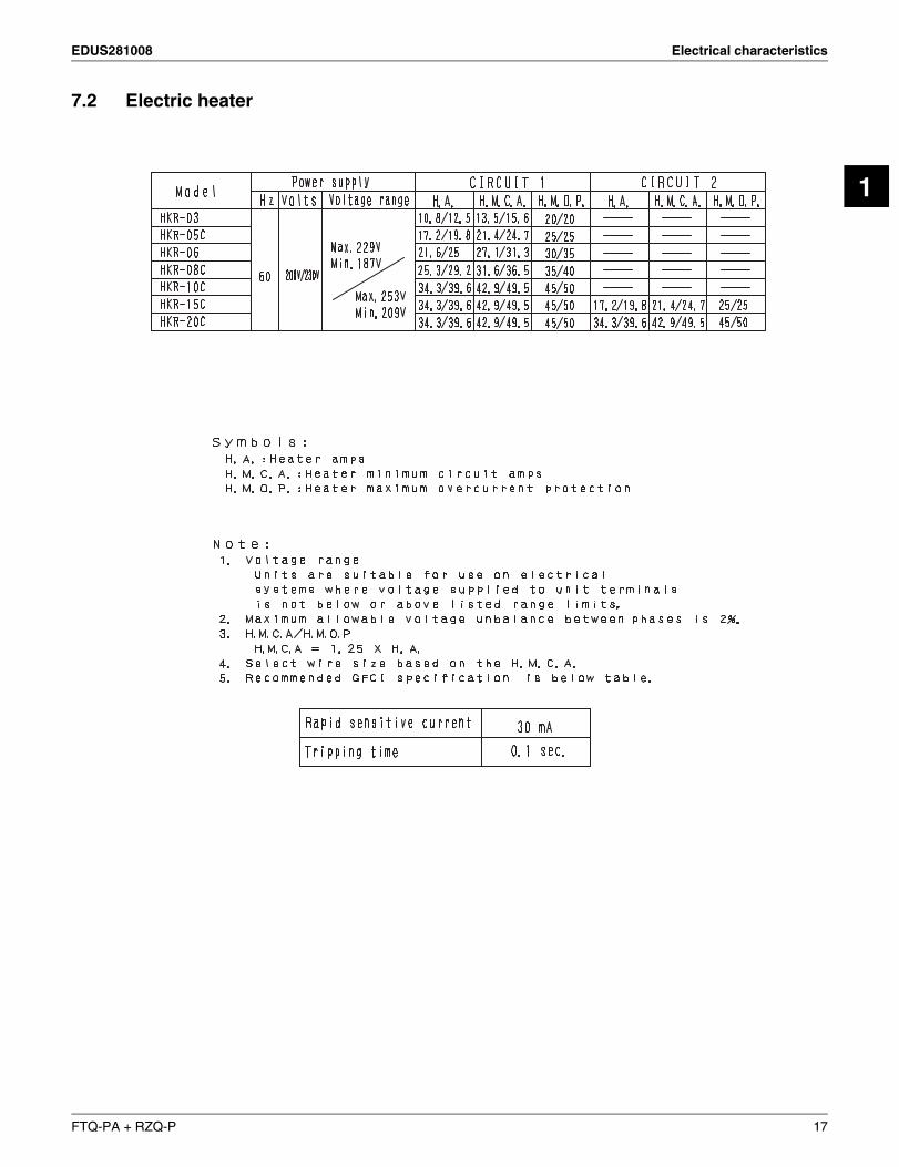
SYMBOLS:MCA : Minimum Circuit Amps (A)MOP : Maximum Overcurrent Protective Device (A)IFM : Indoor Fan MotorHP : Fan Motor Rated Output (HP)FLA : Full Load Amps (A)
NOTES: 1. Voltage range Units are suitable for use on electrical systems where voltage supplied to unit terminals is not below or above listed range limits.2. Maximum allowable voltage imbalance between phases is 2%.3. Select wire size based on MCA.
4D
16 FTQ-PA + RZQ-P
EDUS281008 Electrical characteristics
1
7.2 Electric heater
FTQ-PA + RZQ-P 17
Electrical characteristics EDUS281008
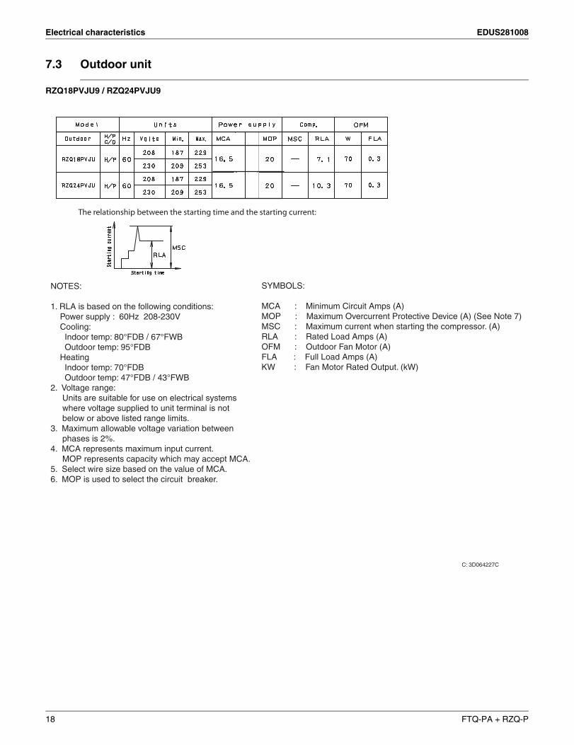
7.3 Outdoor unit
RZQ18PVJU9 / RZQ24PVJU9
C: 3D064227C
(ground leakage circuit breaker).
SYMBOLS:
MCA : Minimum Circuit Amps (A)MOP : Maximum Overcurrent Protective Device (A) (See Note 7)MSC : Maximum current when starting the compressor. (A)RLA : Rated Load Amps (A)OFM : Outdoor Fan Motor (A)FLA : Full Load Amps (A)KW : Fan Motor Rated Output. (kW)
NOTES: 1. RLA is based on the following conditions: Power supply : 60Hz 208-230V Cooling: Indoor temp: 80°FDB / 67°FWB Outdoor temp: 95°FDB Heating Indoor temp: 70°FDB Outdoor temp: 47°FDB / 43°FWB2. Voltage range: Units are suitable for use on electrical systems where voltage supplied to unit terminal is not below or above listed range limits.3. Maximum allowable voltage variation between phases is 2%.4. MCA represents maximum input current. MOP represents capacity which may accept MCA.5. Select wire size based on the value of MCA.6. MOP is used to select the circuit breaker.
The relationship between the starting time and the starting current:
18 FTQ-PA + RZQ-P
EDUS281008 Safety devices setting
1
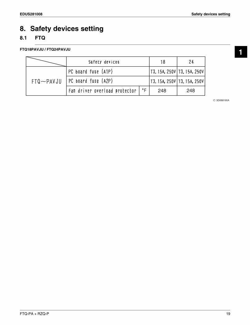
8. Safety devices setting8.1 FTQ
FTQ18PAVJU / FTQ24PAVJU
F 248 248
C: 3D068195A
FTQ-PA + RZQ-P 19
Capacity tables EDUS281008
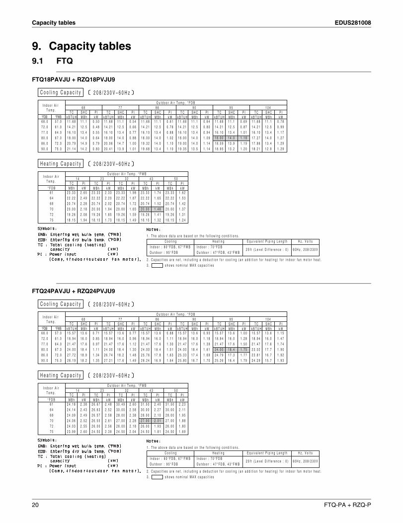
9. Capacity tables9.1 FTQ
FTQ18PAVJU + RZQ18PVJU9
FTQ24PAVJU + RZQ24PVJU9
C o o l i n g C a p a c i t y 2 0 8 / 2 3 0 V – 6 0 H z
2 0 8 / 2 3 0 V – 6 0 H z
I n d o o r A i r T e m p .
O u t d o o r A i r T e m p . ° F D B
°FDB °FWB
6 8 7 7 8 6 9 0 9 5 1 0 4T C
k B T U HS H CM B h
P Ik W
T Ck B T U H
S H CM B h
P Ik W
T Ck B T U H
S H CM B h
P Ik W
T Ck B T U H
S H CM B h
P Ik W
T Ck B T U H
S H CM B h
P Ik W
T Ck B T U H
S H CM B h
P Ik W
H e a t i n g C a p a c i t y
I n d o o r A i rT e m p .
O u t d o o r A i r T e m p . ° F W B
° F D B
1 4 2 3 3 2 4 3 5 0T C
M B hP Ik W
T CM B h
P Ik W
T CM B h
P Ik W
T CM B h
P Ik W
T CM B h
P Ik W
C o o l i n gI n d o o r : 8 0 ° F D B , 6 7 ° F W BO u t d o o r : 9 5 ° F D B
H e a t i n gI n d o o r : 7 0 ° F D BO u t d o o r : 4 7 ° F D B , 4 3 ° F W B
E q u i v a l e n t P i p i n g L e n g t h
2 5 f t ( L e v e l D i f f e r e n c e : 0 )
H z , V o l t s
6 0 H z , 2 0 8 / 2 3 0 V
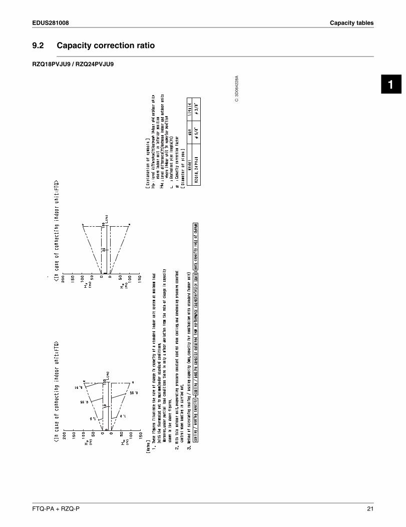
1 . T h e a b o v e d a t a a r e b a s e d o n t h e f o l l o w i n g c o n d i t i o n s .
2 . C a p a c i t i e s a r e n e t , i n c l u d i n g a d e d u c t i o n f o r c o o l i n g ( a n a d d i t i o n f o r h e a t i n g ) f o r i n d o o r f a n m o t o r h e a t .3 . s h o w s n o m i n a l M A X c a p a c i t i e s
6 8 . 07 2 . 07 7 . 08 0 . 08 6 . 09 0 . 0
5 7 . 06 1 . 06 4 . 06 7 . 07 2 . 07 5 . 0
1 1 . 6 81 4 . 2 11 6 . 1 01 8 . 0 02 0 . 7 92 1 . 1 4
1 1 . 11 2 . 51 3 . 41 4 . 01 4 . 91 4 . 2
0 . 5 00 . 4 80 . 5 50 . 6 40 . 7 90 . 8 0
1 1 . 6 81 4 . 2 11 6 . 1 01 8 . 0 02 0 . 0 62 0 . 4 1
1 1 . 11 2 . 51 3 . 41 4 . 01 4 . 71 3 . 9
0 . 5 40 . 6 60 . 7 70 . 8 81 . 0 01 . 0 1
1 1 . 6 81 4 . 2 11 6 . 1 01 8 . 0 01 9 . 3 21 9 . 6 8
1 1 . 11 2 . 51 3 . 41 4 . 01 4 . 01 3 . 4
0 . 6 10 . 7 60 . 8 81 . 0 21 . 1 01 . 1 0
1 1 . 6 81 4 . 2 11 6 . 1 01 8 . 0 01 9 . 0 01 9 . 3 5
1 1 . 11 2 . 51 3 . 41 4 . 01 4 . 01 3 . 5
0 . 6 40 . 8 00 . 9 41 . 0 91 . 1 41 . 1 4
1 1 . 6 81 4 . 2 11 6 . 1 01 8 . 0 01 8 . 5 91 8 . 9 5
1 1 . 11 2 . 51 3 . 41 4 . 01 3 . 91 3 . 2
0 . 6 90 . 8 71 . 0 11 . 1 81 . 1 91 . 2 0
1 1 . 6 81 4 . 2 11 6 . 1 01 7 . 2 71 7 . 8 61 8 . 2 1
1 1 . 11 2 . 51 3 . 41 4 . 01 3 . 41 2 . 9
0 . 7 80 . 9 91 . 1 71 . 2 71 . 2 91 . 2 9
6 16 46 87 07 27 5
2 . 6 52 . 4 92 . 2 82 . 1 82 . 0 81 . 9 4
2 3 . 3 32 2 . 2 22 0 . 7 42 0 . 0 01 9 . 2 61 8 . 1 5
2 3 . 3 32 2 . 2 22 0 . 7 42 0 . 0 01 9 . 2 61 8 . 1 5
2 . 3 32 . 2 02 . 0 21 . 9 41 . 8 51 . 7 3
2 3 . 3 32 2 . 2 22 0 . 7 42 0 . 0 01 9 . 2 61 8 . 1 5
1 . 9 81 . 8 71 . 7 21 . 6 51 . 5 91 . 4 9
2 3 . 3 32 2 . 2 22 0 . 7 42 0 . 0 01 9 . 2 61 8 . 1 5
1 . 7 41 . 6 51 . 5 21 . 4 61 . 4 11 . 3 2
2 3 . 3 32 2 . 2 22 0 . 7 42 0 . 0 01 9 . 2 61 8 . 1 5
1 . 6 21 . 5 31 . 4 21 . 3 71 . 3 11 . 2 4
C o o l i n g C a p a c i t y
O u t d o o r A i r T e m p . ° F D B6 8 7 7 8 6 9 0 9 5 1 0 4
T Ck B T U H
S H CM B h
P Ik W
T Ck B T U H
S H CM B h
P Ik W
T Ck B T U H
S H CM B h
P Ik W
T Ck B T U H
S H CM B h
P Ik W
T Ck B T U H
S H CM B h
P Ik W
T Ck B T U H
S H CM B h
P Ik W
H e a t i n g C a p a c i t y
O u t d o o r A i r T e m p . ° F W B1 4 2 3 3 2 4 3 5 0
T CM B h
P Ik W
T CM B h
P Ik W
T CM B h
P Ik W
T CM B h
P Ik W
T CM B h
P Ik W
C o o l i n gI n d o o r : 8 0 ° F D B , 6 7 ° F W BO u t d o o r : 9 5 ° F D B
H e a t i n gI n d o o r : 7 0 ° F D BO u t d o o r : 4 7 ° F D B , 4 3 ° F W B
E q u i v a l e n t P i p i n g L e n g t h
2 5 f t ( L e v e l D i f f e r e n c e : 0 )
H z , V o l t s
6 0 H z , 2 0 8 / 2 3 0 V
1 . T h e a b o v e d a t a a r e b a s e d o n t h e f o l l o w i n g c o n d i t i o n s .
2 . C a p a c i t i e s a r e n e t , i n c l u d i n g a d e d u c t i o n f o r c o o l i n g ( a n a d d i t i o n f o r h e a t i n g ) f o r i n d o o r f a n m o t o r h e a t .3 . s h o w s n o m i n a l M A X c a p a c i t i e s
2 0 8 / 2 3 0 V – 6 0 H z
2 0 8 / 2 3 0 V – 6 0 H z
I n d o o r A i r T e m p .
°FDB °FWB
I n d o o r A i rT e m p .
° F D B
1 5 . 5 71 8 . 9 42 1 . 4 72 4 . 0 02 7 . 7 22 8 . 1 9
1 3 . 61 6 . 01 7 . 61 8 . 41 8 . 91 8 . 2
0 . 7 10 . 8 50 . 9 71 . 1 11 . 3 41 . 3 5
1 5 . 5 71 8 . 9 42 1 . 4 72 4 . 0 02 6 . 7 42 7 . 2 1
1 3 . 61 6 . 01 7 . 61 8 . 41 8 . 21 7 . 6
0 . 7 70 . 9 61 . 1 21 . 3 01 . 4 81 . 4 9
1 5 . 5 71 8 . 9 42 1 . 4 72 4 . 0 02 5 . 7 62 6 . 2 4
1 3 . 61 6 . 01 7 . 61 8 . 41 7 . 81 6 . 9
0 . 8 81 . 1 11 . 3 01 . 5 11 . 6 31 . 6 4
1 5 . 5 71 8 . 9 42 1 . 4 72 4 . 0 02 5 . 3 32 5 . 8 0
1 3 . 61 6 . 01 7 . 61 8 . 41 7 . 41 6 . 7
0 . 9 31 . 1 81 . 3 91 . 6 11 . 6 91 . 7 0
1 5 . 5 71 8 . 9 42 1 . 4 72 4 . 0 02 4 . 7 92 5 . 2 6
1 3 . 61 6 . 01 7 . 61 8 . 41 7 . 31 6 . 4
1 . 0 01 . 2 81 . 5 01 . 7 51 . 7 71 . 7 9
1 5 . 5 71 8 . 9 42 1 . 4 72 3 . 0 22 3 . 8 12 4 . 2 9
1 3 . 61 6 . 01 7 . 61 7 . 71 6 . 71 5 . 7
1 . 1 51 . 4 71 . 7 41 . 9 01 . 9 21 . 9 3
6 16 46 87 07 27 5
2 . 3 82 . 4 32 . 4 92 . 5 22 . 5 52 . 6 0
2 4 . 1 82 4 . 1 42 4 . 0 92 4 . 0 62 4 . 0 32 3 . 9 9
2 6 . 6 72 6 . 6 32 6 . 5 72 6 . 5 52 6 . 0 02 4 . 5 0
2 . 4 82 . 5 22 . 5 82 . 6 12 . 5 62 . 3 9
3 0 . 4 93 0 . 0 02 8 . 0 02 7 . 0 02 6 . 0 02 4 . 5 0
2 . 6 02 . 5 82 . 3 82 . 2 82 . 1 82 . 0 4
3 1 . 5 03 0 . 0 02 8 . 0 02 7 . 0 02 6 . 0 02 4 . 5 0
2 . 4 02 . 2 72 . 1 02 . 0 11 . 9 31 . 8 1
3 1 . 5 03 0 . 0 02 8 . 0 02 7 . 0 02 6 . 0 02 4 . 5 0
2 . 2 32 . 1 11 . 9 51 . 8 81 . 8 01 . 6 9
6 8 . 07 2 . 07 7 . 08 0 . 08 6 . 09 0 . 0
5 7 . 06 1 . 06 4 . 06 7 . 07 2 . 07 5 . 0
20 FTQ-PA + RZQ-P
EDUS281008 Capacity tables
1
9.2 Capacity correction ratio
RZQ18PVJU9 / RZQ24PVJU9
C: 3
D06
4228
A
FTQ-PA + RZQ-P 21
Operation limits EDUS281008
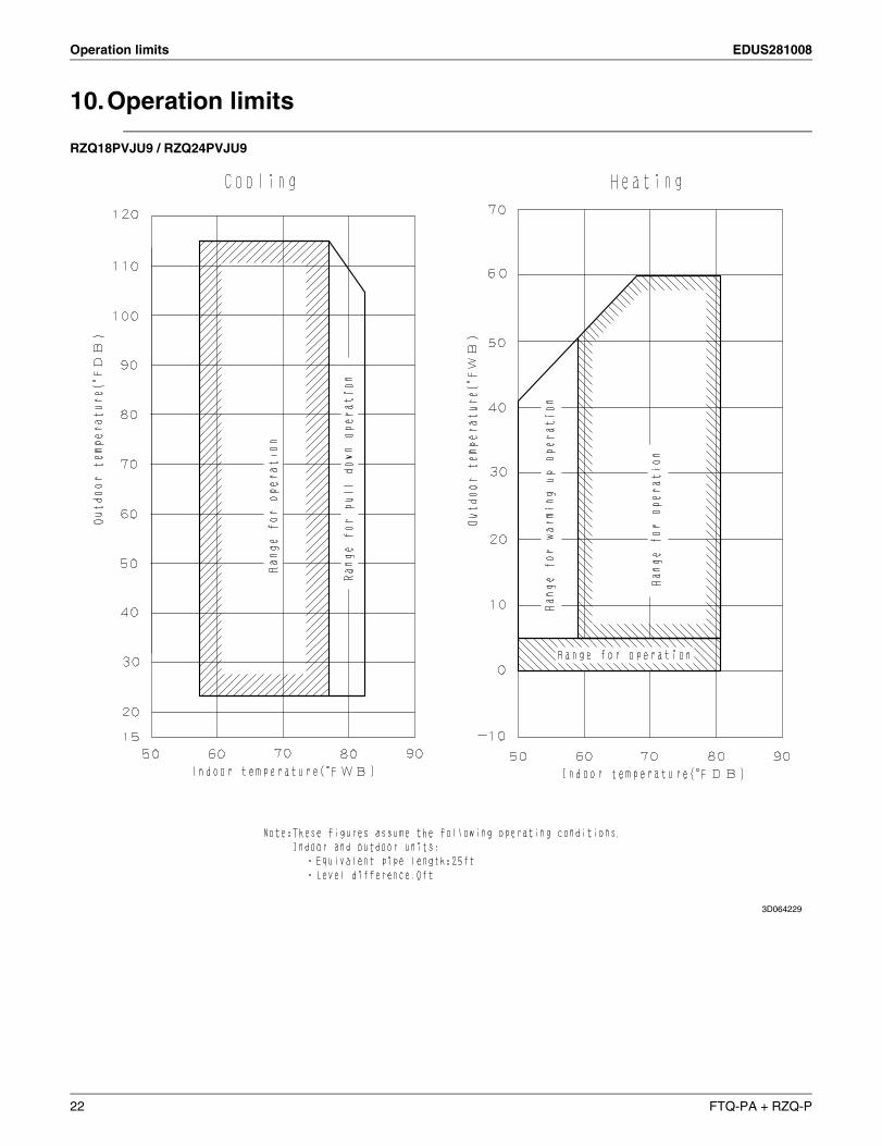
10.Operation limits
RZQ18PVJU9 / RZQ24PVJU9
3D064229
22 FTQ-PA + RZQ-P
EDUS281008
Installation of indoor / outdoor unit 23
2
Part 2
Installation ofindoor / outdoor unit
1. Center of gravity........................................................................................241.1 Outdoor unit................................................................................................ 24
2. Installation of indoor unit ...........................................................................252.1 FTQ18PAVJU / FTQ24PAVJU................................................................... 25
3. Installation of outdoor unit .........................................................................413.1 RZQ18PVJU9 / RZQ24PVJU9................................................................... 41
Center of gravity EDUS281008
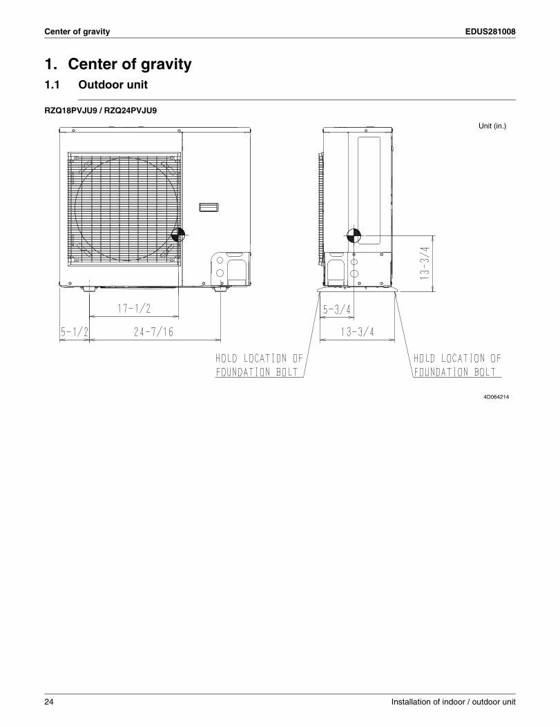
1. Center of gravity1.1 Outdoor unit
RZQ18PVJU9 / RZQ24PVJU9
Unit (in.)
4D064214
24 Installation of indoor / outdoor unit
EDUS281008 Installation of indoor unit
2
2. Installation of indoor unit2.1 FTQ18PAVJU / FTQ24PAVJU
3P250363-3B
1 English
SPLIT SYSTEM Air Conditioners Installation manual
CONTENTS1. SAFETY CONSIDERATIONS ........................................... 12. BEFORE INSTALLATION .................................................. 33. SELECTING INSTALLATION SITE ................................... 34. PREPARATIONS BEFORE INSTALLATION AND
INSTALLATION .................................................................. 45. REFRIGERANT PIPING WORK ....................................... 66. DRAIN PIPING WORK ...................................................... 77. INSTALLING THE DUCT ................................................... 88. ELECTRIC WIRING WORK .............................................. 89. WIRING EXAMPLE ........................................................... 9
10. FIELD SETTING AND TEST RUN .................................. 12
SAFETY CONSIDERATIONS1. Read these “SAFETY CONSIDERATIONS for Installation” carefully before installing an air conditioner or heat pump. After completing the installation, make sure that the unit operates properly during the startup operation.Instruct the customer on how to operate and maintain the unit. Inform customers that they should store this Installation Manu-al with the Operation Manual for future reference.Always use a licensed installer or contractor to install this product. Improper installation can result in water or refrigerant leakage, electrical shock, fi re, or explosion.Meanings of DANGER, WARNING, CAUTION, and NOTESymbols:
DANGER ................ Indicates an imminently hazardous situation which, if not avoided, will result in death or serious injury.
WARNING .............. Indicates a potentially hazardous situation which, if not avoided, could result in death or serious injury.
CAUTION ............... Indicates a potentially hazardous situation which, if not avoided, may result in minor or moderate injury. It may also be used to alert against unsafe practices.
NOTE...................... Indicates situations that may result in equipment or property-damage accidents only.
DANGER
Refrigerant gas is heavier than air and replaces oxygen. •A massive leak can lead to oxygen depletion, especially in basements, and an asphyxiation hazard could occur leading to serious injury or death.
Do not ground units to water pipes, gas pipes, tele-•phone wires, or lightning rods as incomplete grounding can cause a severe shock hazard resulting in severe injury or death. Additionally, grounding to gas pipes could cause a gas leak and potential explosion causing severe injury or death.
If refrigerant gas leaks during installation, ventilate the •area immediately. Refrigerant gas may produce toxic gas if it comes in contact with fi re. Exposure to this gas could cause severe injury or death.
After completing the installation work, check that the •refrigerant gas does not leak throughout the system.
Do not install unit in an area where fl ammable materials •are present due to risk of explosions that can cause serious injury or death.
Safely dispose all packing and transportation materials •in accordance with federal/state/local laws or ordinanc-es. Packing materials such as nails and other metal or wood parts, including plastic packing materials used for transportation may cause injuries or death by suffoca-tion.
WARNING
All phases of the fi eld-installation, including, but not •limited to, electrical, piping, safety, etc. must be in ac-cordance with manufacturer's instructions and must comply with national, state, provincial and local codes.
Only qualifi ed personnel must carry out the installation •work. Installation must be done in accordance with this installation manual. Improper installation may result in water leakage, electric shock, or fi re.
When installing the unit in a small room, take measures •to keep the refrigerant concentration from exceeding allowable safety limits. Excessive refrigerant leaks, in the event of an accident in a closed ambient space, can lead to oxygen defi ciency.
Use only specifi ed accessories and parts for installation •work. Failure to use specifi ed parts may result in water leakage, electric shocks, fi re, or the unit falling.
Install the air conditioner or heat pump on a foundation •strong enough that it can withstand the weight of the unit. A foundation of insuffi cient strength may result in the unit falling and causing injuries.
Take into account strong winds, typhoons, or earth-•quakes when installing. Improper installation may result in the unit falling and causing accidents.
Make sure that a separate power supply circuit is pro-•vided for this unit and that all electrical work is carried out by qualifi ed personnel according to local, state, and national regulations. An insuffi cient power supply capacity or improper electrical construction may lead to electric shocks or fi re.
Make sure that all wiring is secured, that specifi ed wires •are used, and that no external forces act on the terminal connections or wires. Improper connections or installa-tion may result in fi re.
When wiring, position the wires so that the electric com-•ponent box cover can be securely fastened. Improper positioning of the electric component box cover may result in electric shocks, fi re, or the terminals overheating.
Before touching electrical parts, turn off the unit.•
Installation of indoor / outdoor unit 25
Installation of indoor unit EDUS281008
3P250363-3B
English 2
It is recommended to install a ground fault circuit inter-•rupter if one is not already available. This helps prevent electrical shocks or fi re.
Securely fasten the outside unit terminal cover (panel). •If the terminal cover/panel is not installed properly, dust or water may enter the outside unit causing fi re or electric shock.
When installing or relocating the system, keep the •refrigerant circuit free from substances other than the specifi ed refrigerant (R-410A) such as air. Any presence of air or other foreign substance in the refrigerant cir-cuit can cause an abnormal pressure rise or rupture, resulting in injury.
Do not change the setting of the protection devices. If •the pressure switch, thermal switch, or other protection device is shorted and operated forcibly, or parts other than those specifi ed by Daikin are used, fi re or explo-sion may occur.
CAUTION
Do not touch the switch with wet fi ngers. Touching a •switch with wet fi ngers can cause electric shock.
Do not allow children to play on or around the unit to •prevent injury.
Do not touch the refrigerant pipes during and immedi-•ately after operation as the refrigerant pipes may be hot or cold, depending on the condition of the refrigerant fl owing through the refrigerant piping, compressor, and other refrigerant cycle parts. Your hands may suffer burns or frostbite if you touch the refrigerant pipes. To avoid injury, give the pipes time to return to normal temperature or, if you must touch them, be sure to wear proper gloves.
Install drain piping to proper drainage. Improper drain •piping may result in water leakage and property damage.
Insulate piping to prevent condensation.•
Be careful when transporting the product.•
Do not turn off the power immediately after stopping •operation. Always wait for at least 5 minutes before turning off the power. Otherwise, water leakage may occur.
Do not use a charging cylinder. Using a charging cylin-•der may cause the refrigerant to deteriorate.
Refrigerant R-410A in the system must be kept clean, •dry, and tight.
Clean and Dry -- Foreign materials (including min-(a)eral oils such as SUNISO oil or moisture) should be prevented from getting into the system.
Tight -- R-410A does not contain any chlorine, does (b)not destroy the ozone layer, and does not reduce the earth’s protection again harmful ultraviolet radiation. R-410A can contribute to the greenhouse effect if it is released. Therefore take proper measures to check for the tightness of the refrigerant piping installation. Read the chapter Refrigerant Piping and follow the procedures.
Since R-410A is a blend, the required additional refriger-•ant must be charged in its liquid state. If the refrigerant is charged in a state of gas, its composition can change
and the system will not work properly.
The indoor unit is for R-410A. See the catalog for indoor •models that can be connected. Normal operation is not possible when connected to other units.
Remote controller (wireless kit) transmitting distance •can be shorter than expected in rooms with electronic fl uorescent lamps (inverter or rapid start types). Install the indoor unit far away from fl uorescent lamps as much as possible.
Indoor units are for indoor installation only. Outdoor •units can be installed either outdoors or indoors. This unit is for indoor use.
Do not install the air conditioner or heat pump in the •following locations:
Where a mineral oil mist or oil spray or vapor is (a)produced, for example, in a kitchen.Plastic parts may deteriorate and fall off or result in water leakage.
Where corrosive gas, such as sulfurous acid gas, is (b)produced.Corroding copper pipes or soldered parts may result in refrigerant leakage.
Near machinery emitting electromagnetic waves.(c)Electromagnetic waves may disturb the operation of the control system and cause the unit to malfunc-tion.
Where fl ammable gas may leak, where there is (d)carbon fi ber, or ignitable dust suspension in the air, or where volatile fl ammables such as thinner or gasoline are handled. Operating the unit in such conditions can cause a fi re.
Take adequate measures to prevent the outside unit •from being used as a shelter by small animals. Small animals making contact with electrical parts can cause malfunctions, smoke, or fi re. Instruct the customer to keep the area around the unit clean.
NOTE
Install the power supply and control wires for the indoor •and outdoor units at least 3.5 feet away from televisions or radios to prevent image interference or noise. De-pending on the radio waves, a distance of 3.5 feet may not be suffi cient to eliminate the noise.
Dismantling the unit, treatment of the refrigerant, oil and •additional parts must be done in accordance with the relevant local, state, and national regulations.
Do not use the following tools that are used with con-•ventional refrigerants: gauge manifold, charge hose, gas leak detector, reverse fl ow check valve, refrigerant charge base, vacuum gauge, or refrigerant recovery equipment.
If the conventional refrigerant and refrigerator oil are •mixed in R-410A, the refrigerant may deteriorate.
This air conditioner or heat pump is an appliance that •should not be accessible to the general public.
As design pressure is 4 psi, the wall thickness of •fi eld-installed pipes should be selected in accordance with the relevant local, state, and national regulations.
26 Installation of indoor / outdoor unit
EDUS281008 Installation of indoor unit
2
3P250363-3B
BEFORE INSTALLATION2.
WARNING
Entrust installation to the place of purchase or a qualifi ed •serviceman. Improper installation could lead to leaks and, in worse cases, electric shock or fi re.Use of unspecifi ed parts could lead to the unit falling, leaks •and, in worse cases, electric shock or fi re.
NOTE
Be sure to read this manual before installing the indoor unit.•Be sure to mount an air fi lter (part to be procured in the •fi eld) in the suction air passage in order to prevent water leaking, etc.
The accessories needed for installation must be retained in your custody until the installation work is completed. Do not discard them.
Decide upon a line of transport.1. Leave the unit inside its packaging while moving, until 2. reaching the installation site. Where unpacking is unavoid-able, use a sling of soft material or protective plates togeth-er with a rope when lifting, to avoid damage or scratches to the unit.
Be sure to check the type of R410A refrigerant to be used before installing the unit.(Using an incorrect refrigerant will prevent normal opera-tion of the unit.)For the installation of an outdoor unit, refer to the installation manual attached to the outdoor unit.
PRECAUTIONS2-1Be sure to instruct customers how to properly operate the •unit (operating different functions, and adjusting the tem-perature) by having them carry out operations themselves while looking at the operation manual.Do not install in locations where the air contains high levels of •salt such as that near the ocean and where voltage fl uctuates greatly such as that in factories, or in vehicles or vessels.
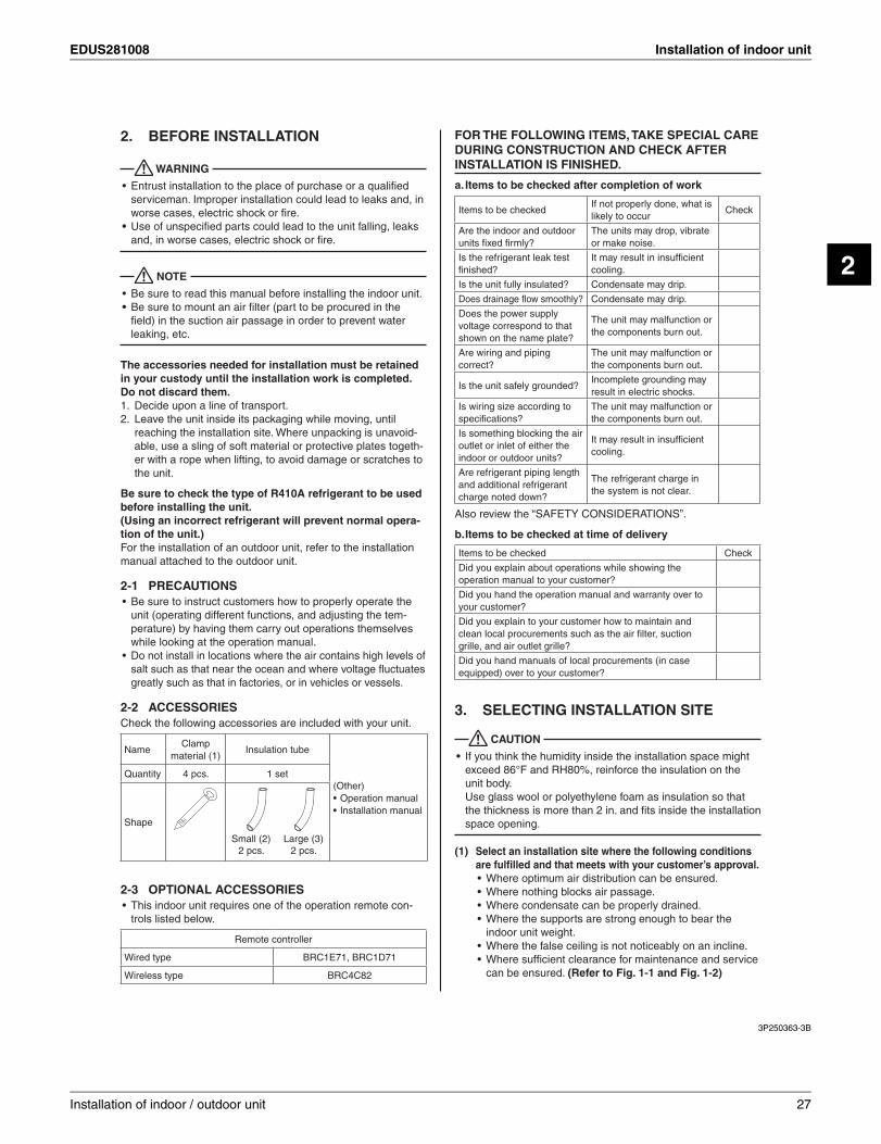
ACCESSORIES2-2Check the following accessories are included with your unit.
NameClamp
material (1)Insulation tube
(Other)Operation manual •Installation manual •
Quantity 4 pcs. 1 set
Shape
Small (2)2 pcs.
Large (3)2 pcs.
OPTIONAL ACCESSORIES2-3This indoor unit requires one of the operation remote con-•trols listed below.
Remote controller
Wired type BRC1E71, BRC1D71
Wireless type BRC4C82
FOR THE FOLLOWING ITEMS, TAKE SPECIAL CARE DURING CONSTRUCTION AND CHECK AFTER INSTALLATION IS FINISHED.
a. Items to be checked after completion of work
Items to be checkedIf not properly done, what is likely to occur
Check
Are the indoor and outdoor units fi xed fi rmly?
The units may drop, vibrate or make noise.
Is the refrigerant leak test fi nished?
It may result in insuffi cient cooling.
Is the unit fully insulated? Condensate may drip.
Does drainage fl ow smoothly? Condensate may drip.
Does the power supply voltage correspond to that shown on the name plate?
The unit may malfunction or the components burn out.
Are wiring and piping correct?
The unit may malfunction or the components burn out.
Is the unit safely grounded?Incomplete grounding may result in electric shocks.
Is wiring size according to specifi cations?
The unit may malfunction or the components burn out.
Is something blocking the air outlet or inlet of either the indoor or outdoor units?
It may result in insuffi cient cooling.
Are refrigerant piping length and additional refrigerant charge noted down?
The refrigerant charge in the system is not clear.
Also review the “SAFETY CONSIDERATIONS”.
b. Items to be checked at time of delivery
Items to be checked Check
Did you explain about operations while showing the operation manual to your customer?
Did you hand the operation manual and warranty over to your customer?
Did you explain to your customer how to maintain and clean local procurements such as the air fi lter, suction grille, and air outlet grille?
Did you hand manuals of local procurements (in case equipped) over to your customer?
SELECTING INSTALLATION SITE3.
CAUTION
If you think the humidity inside the installation space might •exceed 86°F and RH80%, reinforce the insulation on the unit body.Use glass wool or polyethylene foam as insulation so that the thickness is more than 2 in. and fi ts inside the installation space opening.
Select an installation site where the following conditions (1)are fulfi lled and that meets with your customer’s approval.
Where optimum air distribution can be ensured.•Where nothing blocks air passage.•Where condensate can be properly drained.•Where the supports are strong enough to bear the •indoor unit weight.Where the false ceiling is not noticeably on an incline.•Where suffi cient clearance for maintenance and service •can be ensured. (Refer to Fig. 1-1 and Fig. 1-2)
Installation of indoor / outdoor unit 27
Installation of indoor unit EDUS281008
3P250363-3B
English 4
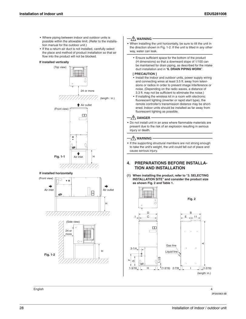
Where piping between indoor and outdoor units is •possible within the allowable limit. (Refer to the installa-tion manual for the outdoor unit.)If the a return-air duct is not installed, carefully select •the place and method of product installation so that air fl ow into the product will not be blocked.
If installed vertically
24 or more
(length : in.)
(Top view)
H
(Front view)Air outlet
Air inletFig. 1-1
If installed horizontally
H
(Front view)
Air outletAir inlet
24 or more
(Side view)
HFig. 1-2
WARNING
When installing the unit horizontally, be sure to tilt the unit in •the direction shown in Fig. 1-2. If the unit is tilted in any other way, water can leak.
Ensure suffi cient space for the bottom of the product •(H dimensions) so that a downward slope of 1/100 can be maintained for drain piping, as described for the intake duct installation and in “6. DRAIN PIPING WORK”.
[ PRECAUTION ]Install the indoor and outdoor units, power supply wiring •and connecting wires at least 3.5 ft. away from televi-sions or radios in order to prevent image interference or noise. (Depending on the radio waves, a distance of 3.3 ft. may not be suffi cient to eliminate the noise.)If installing the wireless kit in a room with electronic •fl uorescent lighting (inverter or rapid start type), the remote controller’s transmission distance may be short-ened. Indoor units should be installed as far away from fl uorescent lighting as possible.
DANGER
Do not install unit in an area where fl ammable materials are •present due to the risk of an explosion resulting in serious injury or death.
WARNING
If the supporting structural members are not strong enough •to take the unit’s weight, the unit could fall out of place and cause serious injury.
PREPARATIONS BEFORE INSTALLA-4. TION AND INSTALLATION
When installing the product, refer to “3. SELECTING (1)INSTALLATION SITE” and consider the product size as shown Fig. 2 and Table 1.
CD
11EB
A
F G 1-1/
8
Gas line
H1-3/16 (1-3/16)
1
3-1/4
I2-7/8 (1-3/16)
Liquid line
(length: in.)
Fig. 2
28 Installation of indoor / outdoor unit
EDUS281008 Installation of indoor unit
2
3P250363-3B
5 English
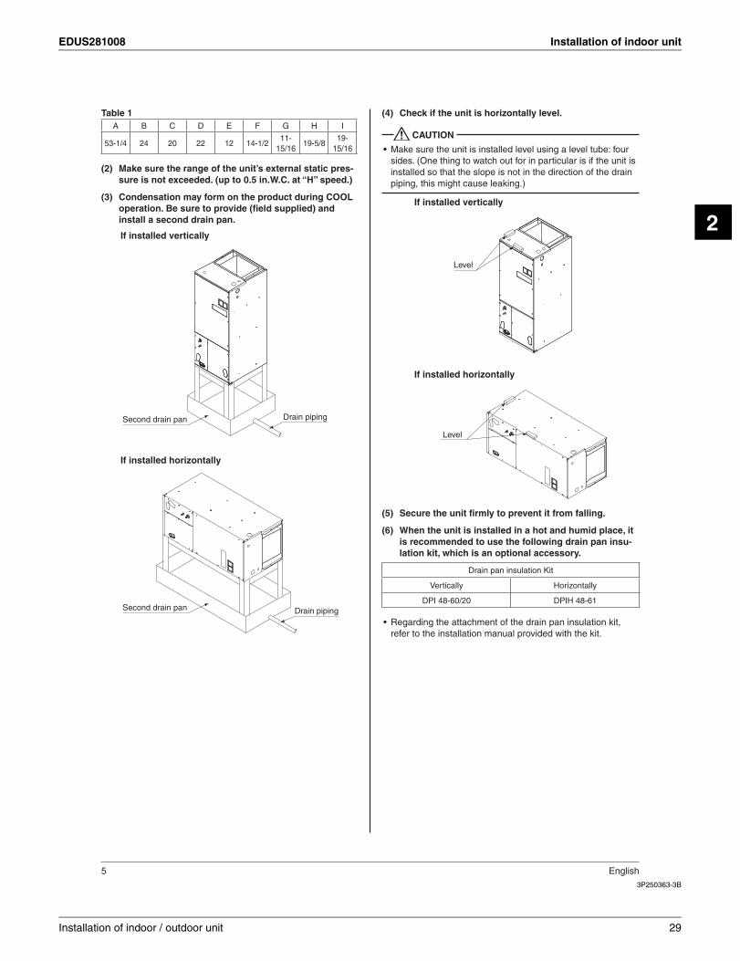
Table 1A B C D E F G H I
53-1/4 24 20 22 12 14-1/211-
15/1619-5/8
19-15/16
Make sure the range of the unit’s external static pres-(2)sure is not exceeded. (up to 0.5 in.W.C. at “H” speed.)
Condensation may form on the product during COOL (3)operation. Be sure to provide (fi eld supplied) and install a second drain pan.
If installed vertically
If installed horizontally
Second drain pan
Second drain pan
Drain piping
Drain piping
Check if the unit is horizontally level.(4)
CAUTION
Make sure the unit is installed level using a level tube: four •sides. (One thing to watch out for in particular is if the unit is installed so that the slope is not in the direction of the drain piping, this might cause leaking.)
Level
Level
If installed vertically
If installed horizontally
Secure the unit fi rmly to prevent it from falling.(5)
When the unit is installed in a hot and humid place, it (6)is recommended to use the following drain pan insu-lation kit, which is an optional accessory.
Drain pan insulation Kit
Vertically Horizontally
DPI 48-60/20 DPIH 48-61
Regarding the attachment of the drain pan insulation kit, •refer to the installation manual provided with the kit.
Installation of indoor / outdoor unit 29
Installation of indoor unit EDUS281008
3P250363-3B
English 6
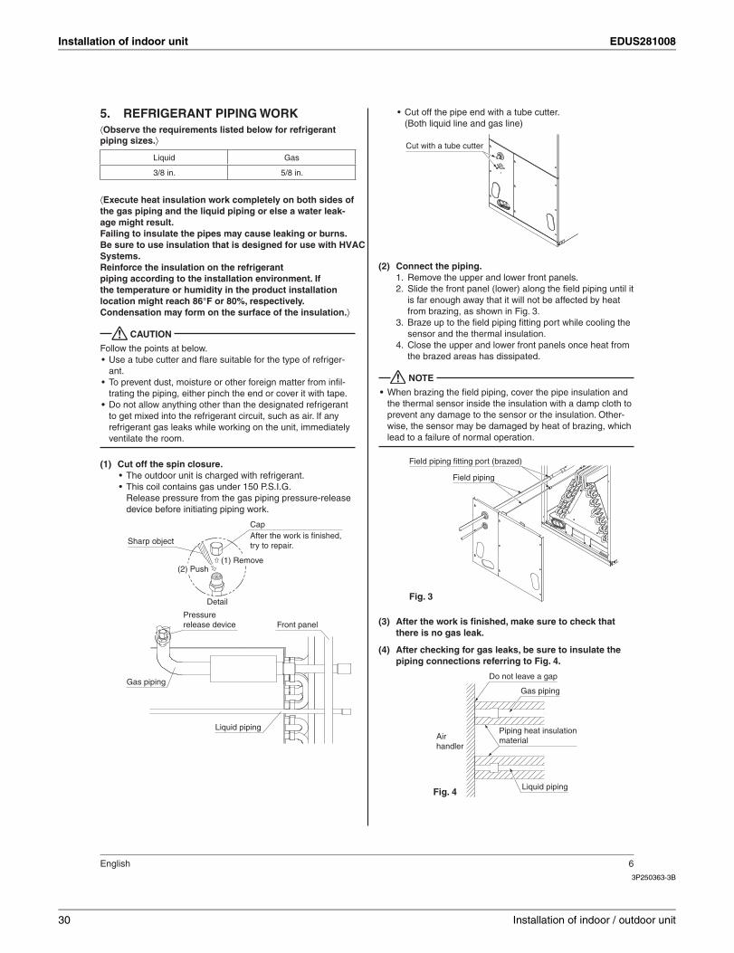
REFRIGERANT PIPING WORK5. ⟨Observe the requirements listed below for refrigerant piping sizes.⟩
Liquid Gas
3/8 in. 5/8 in.
⟨Execute heat insulation work completely on both sides of the gas piping and the liquid piping or else a water leak-age might result.Failing to insulate the pipes may cause leaking or burns.
Reinforce the insulation on the refrigpiping according to the installation environment. If the temperature or humidity in the product installation location might reach 86°F or 80%, respectively. Condensation may form on the surface of the insulation.⟩
CAUTION
Follow the points at below.Use a tube cutter and fl are suitable for the type of refriger-•ant.To prevent dust, moisture or other foreign matter from infi l-•trating the piping, either pinch the end or cover it with tape.Do not allow anything other than the designated refrigerant •to get mixed into the refrigerant circuit, such as air. If any refrigerant gas leaks while working on the unit, immediately ventilate the room.
Cut off the spin closure.(1)The outdoor unit is charged with refrigerant.•This coil contains gas under 150 P.S.I.G.•Release pressure from the gas piping pressure-release device before initiating piping work.
Detail
Cap After the work is finished, try to repair.Sharp object
Gas piping
Front panel
Liquid piping
Pressure release device
(2) Push(1) Remove
Cut off the pipe end with a tube cutter.•(Both liquid line and gas line)
Cut with a tube cutter
Connect the piping.(2)Remove the upper and lower front panels.1. Slide the front panel (lower) along the fi eld piping until it 2. is far enough away that it will not be affected by heat from brazing, as shown in Fig. 3.Braze up to the fi eld piping fi tting port while cooling the 3. sensor and the thermal insulation.Close the upper and lower front panels once heat from 4. the brazed areas has dissipated.
NOTE
When brazing the fi eld piping, cover the pipe insulation and •the thermal sensor inside the insulation with a damp cloth to prevent any damage to the sensor or the insulation. Other-wise, the sensor may be damaged by heat of brazing, which lead to a failure of normal operation.
Field piping fitting port (brazed)
Field piping
Fig. 3
After the work is fi nished, make sure to check that (3)there is no gas leak.
After checking for gas leaks, be sure to insulate the (4)piping connections referring to Fig. 4.
Do not leave a gap
Gas piping
Piping heat insulation material
Liquid piping
Air handler
Fig. 4
30 Installation of indoor / outdoor unit
EDUS281008 Installation of indoor unit
2
3P250363-3B
7 English
CAUTION
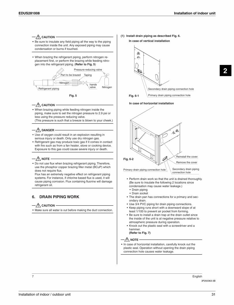
Be sure to insulate any fi eld piping all the way to the piping •connection inside the unit. Any exposed piping may cause condensation or burns if touched.
When brazing the refrigerant piping, perform nitrogen re-•placement fi rst, or perform the brazing while feeding nitro-gen into the refrigerant piping. (Refer to Fig. 5)
Refrigerant piping
Part to be brazed Taping
Pressure-reducing valve
hands valve Nitrogen
Nitrogen
Fig. 5
CAUTION
When brazing piping while feeding nitrogen inside the •piping, make sure to set the nitrogen pressure to 2.9 psi or less using the pressure reducing valve.(This pressure is such that a breeze is blown to your cheek.)
DANGER
Use of oxygen could result in an explosion resulting in •serious injury or death. Only use dry nitrogen gas.Refrigerant gas may produce toxic gas if it comes in contact •with fi re such as from a fan heater, stove or cooking device. Exposure to this gas could cause severe injury or death.
NOTE
Do not use fl ux when brazing refrigerant piping. Therefore, •use the phosphor copper brazing fi ller metal (BCuP) which does not require fl ux.Flux has an extremely negative effect on refrigerant piping systems. For instance, if chlorine based fl ux is used, it will cause piping corrosion. Flux containing fl uorine will damage refrigerant oil.
DRAIN PIPING WORK6.
CAUTION
Make sure all water is out before making the duct connection.•
Install drain piping as described Fig. 6.(1)
Secondary drain piping connection hole
Primary drain piping connection hole
In case of vertical installation
Fig. 6-1
Primary drain piping connection hole
Remove the cover
Secondary drain piping connection hole
Reinstall the cover.
In case of horizontal installation
Fig. 6-2
Perform drain work so that the unit is drained thoroughly. •(Be sure to insulate the following 2 locations since condensation may cause water leakage.)
Drain piping•Drain socket•
The drain pan has connections for a primary and sec-•ondary drain.Use 3/4 PVC piping for drain piping connections.•Keep piping runs short with a downward slope of at •least 1/100 to prevent air pocket from forming.Be sure to install a drain trap at the drain outlet since •the inside of the unit is at negative pressure relative to atmospheric pressure during operation. Knock out the plastic seal with a screwdriver and a •hammer.(Refer to Fig. 7)
NOTE
In case of horizontal installation, carefully knock out the •plastic seal. Operation without opening the drain piping connection hole causes water leakage.
Installation of indoor / outdoor unit 31
Installation of indoor unit EDUS281008
3P250363-3B
English 8
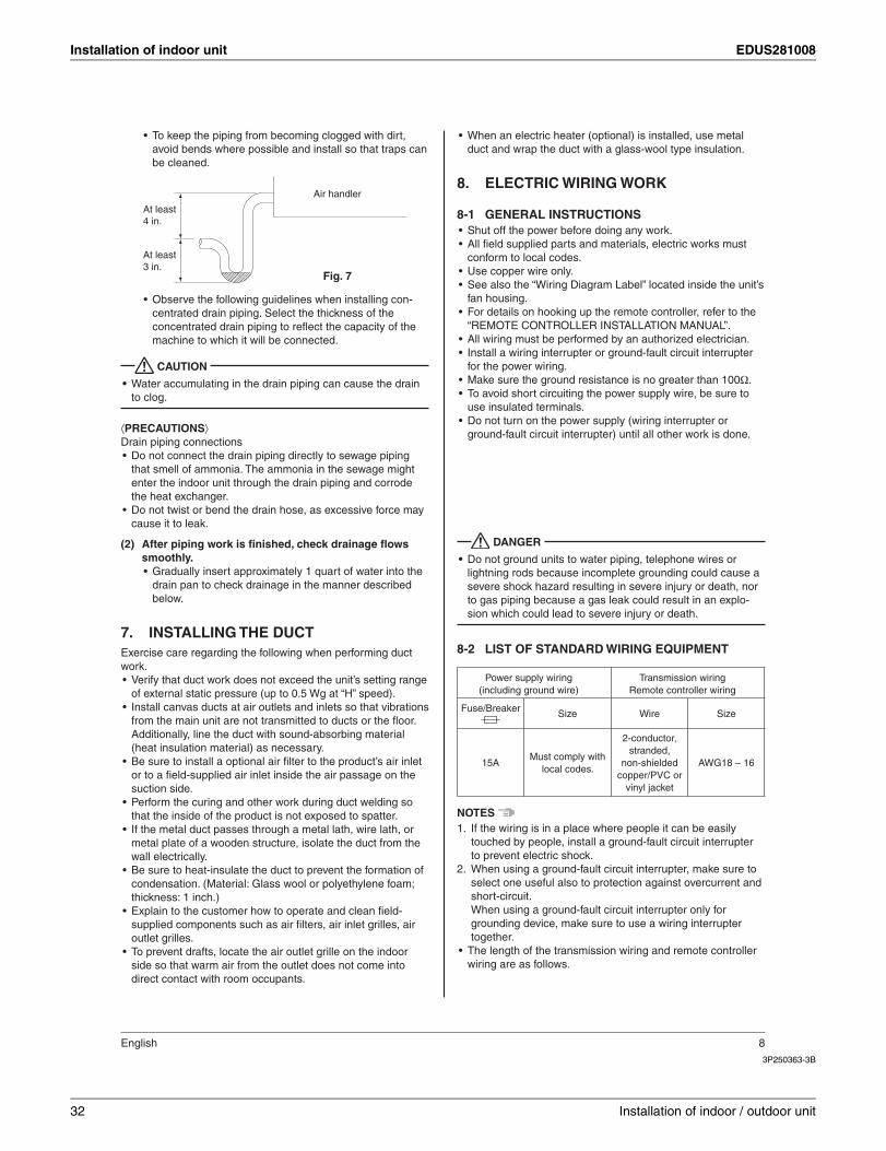
To keep the piping from becoming clogged with dirt, •avoid bends where possible and install so that traps can be cleaned.
Air handler
At least 4 in.
At least 3 in.
Fig. 7
Observe the following guidelines when installing con-•centrated drain piping. Select the thickness of the concentrated drain piping to refl ect the capacity of the machine to which it will be connected.
CAUTION
Water accumulating in the drain piping can cause the drain •to clog.
⟨PRECAUTIONS⟩Drain piping connections
Do not connect the drain piping directly to sewage piping •that smell of ammonia. The ammonia in the sewage might enter the indoor unit through the drain piping and corrode the heat exchanger.Do not twist or bend the drain hose, as excessive force may •cause it to leak.
After piping work is fi nished, check drainage fl ows (2)smoothly.
Gradually insert approximately 1 quart of water into the •drain pan to check drainage in the manner described below.
INSTALLING THE DUCT7. Exercise care regarding the following when performing duct work.
Verify that duct work does not exceed the unit’s setting range •of external static pressure (up to 0.5 Wg at “H” speed).Install canvas ducts at air outlets and inlets so that vibrations •from the main unit are not transmitted to ducts or the fl oor. Additionally, line the duct with sound-absorbing material (heat insulation material) as necessary.Be sure to install a optional air fi lter to the product’s air inlet •or to a fi eld-supplied air inlet inside the air passage on the suction side.Perform the curing and other work during duct welding so •that the inside of the product is not exposed to spatter.If the metal duct passes through a metal lath, wire lath, or •metal plate of a wooden structure, isolate the duct from the wall electrically.Be sure to heat-insulate the duct to prevent the formation of •condensation. (Material: Glass wool or polyethylene foam; thickness: 1 inch.)Explain to the customer how to operate and clean fi eld-•supplied components such as air fi lters, air inlet grilles, air outlet grilles.To prevent drafts, locate the air outlet grille on the indoor •side so that warm air from the outlet does not come into direct contact with room occupants.
When an electric heater (optional) is installed, use metal •duct and wrap the duct with a glass-wool insulation.
ELECTRIC WIRING WORK8.
GENERAL INSTRUCTIONS8-1Shut off the power before doing any work.•All fi eld supplied parts and materials, electric works must •conform to local codes.Use copper wire only.•See also the “Wiring Diagram Label” located inside the unit’s •fan housing.For details on hooking up the remote controller, refer to the •“REMOTE CONTROLLER INSTALLATION MANUAL”.All wiring must be performed by an authorized electrician.•Install a wiring interrupter or ground-fault circuit interrupter •for the power wiring.Make sure the ground resistance is no greater than 100• Ω.To avoid short circuiting the power supply wire, be sure to •use insulated terminals.Do not turn on the power supply (wiring interrupter or •ground-fault circuit interrupter) until all other work is done.
DANGER
Do not ground units to water piping, telephone wires or •lightning rods because incomplete grounding could cause a severe shock hazard resulting in severe injury or death, nor to gas piping because a gas leak could result in an explo-sion which could lead to severe injury or death.
LIST OF STANDARD WIRING EQUIPMENT8-2
Power supply wiring(including ground wire)
Transmission wiringRemote controller wiring
F Size Wire Size
15AMust comply with
local codes.
2-conductor, stranded,
non-shieldedcopper/PVC or
vinyl jacket
AWG18 – 16
NOTES If the wiring is in a place where people it can be easily 1. touched by people, install a ground-fault circuit interrupter to prevent electric shock.When using a ground-fault circuit interrupter, make sure to 2. select one useful also to protection against overcurrent and short-circuit.When using a ground-fault circuit interrupter only for grounding device, make sure to use a wiring interrupter together.
The length of the transmission wiring and remote controller •wiring are as follows.
32 Installation of indoor / outdoor unit
EDUS281008 Installation of indoor unit
2
3P250363-3B
9 English
Length of the transmission wiring and remote controller wiring
Outdoor unit – Indoor unitMax. 3280 ft.
(Total wiring length: 6560 ft.)
Indoor unit – Remote controller Max. 1640 ft.
ELECTRICAL CHARACTERISTICS8-3
Units Power supply Fan motor
Model Hz VoltsVoltage range
MCA MOP HP FLA
18 type60
208/230
Min. 187Max. 229/Min. 207Max. 253
1.415 3/4
1.1
24 type 1.6 1.3
MCA: Minimum Circuit Amps (A) MOP: Max Overcurrent Protective Device (A)HP: Fan motor output (HP) FLA: Full Load Amps (A)
WIRING EXAMPLE9.
HOW TO CONNECT WIRINGS9-1
⟨Precautions when laying power supply wiring⟩Wiring of different thicknesses cannot be connected to the •power supply wiring terminal block. Slack in the power supply wiring may cause abnormal heat.Use sleeve-insulated round crimp-style terminals for con-•nections to the power supply wiring terminal block. When none are available, connect wires of the same diameter to both sides, as shown in the fi gure.
Electric wireRound crimp-style terminal
Insulation sleeve
Connect wires of the same gauge to both sides.
Do not connect wires of the same gauge to one side.
Do not connect wires of different gauges.
If the wiring gets too hot due to loose power-supply wir-ing, use the following precautions:
For wiring, use the designated power supply wiring and •connect fi rmly, then secure to prevent outside pressure being exerted on the terminal board.Use the correct screwdriver for tightening the terminal •screws. If the blade of screwdriver is too small, the head of the screw might be damaged, and the screw will not be properly tightened.If the terminal screws are tightened too hard, screws might •be damaged.Refer to Table 2 for the tightening torque of the terminal •screws.
Table 2Terminal block Tightening torque (ft · lbf)
Remote controller / transmission wiring terminal block (6P) (10P)
0.58 – 0.72
Power supply wiring terminal block (3P)
0.87 – 1.06
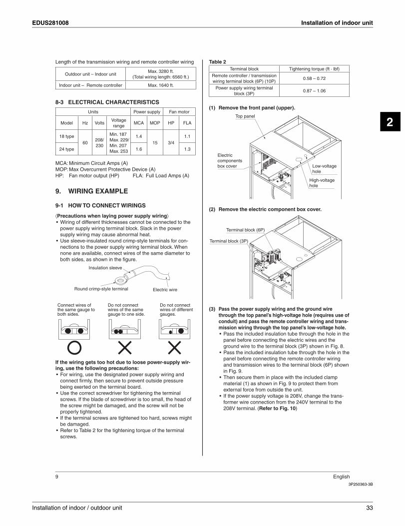
Remove the front panel (upper).(1)
Top panel
Electric components box cover Low-voltage
hole
High-voltage hole
Remove the electric component box cover.(2)
Terminal block (6P)
Terminal block (3P)
Pass the power supply wiring and the ground wire (3)through the top panel’s high-voltage hole (requires use of conduit) and pass the remote controller wiring and trans-mission wiring through the top panel’s low-voltage hole.
Pass the included insulation tube through the hole in the •panel before connecting the electric wires and the ground wire to the terminal block (3P) shown in Fig. 8.Pass the included insulation tube through the hole in the •panel before connecting the remote controller wiring and transmission wires to the terminal block (6P) shown in Fig. 9.Then secure them in place with the included clamp •material (1) as shown in Fig. 9 to protect them from external force from outside the unit.If the power supply voltage is 208V, change the trans-•former wire connection from the 240V terminal to the 208V terminal. (Refer to Fig. 10)
Installation of indoor / outdoor unit 33
Installation of indoor unit EDUS281008
3P250363-3B
English 10
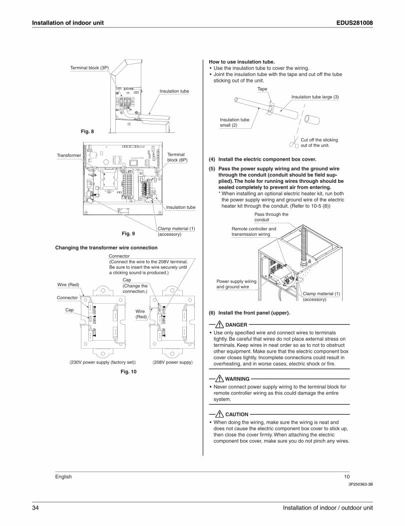
Insulation tube
L 2L1
P OW E R
Terminal block (3P)
Fig. 8
Clamp material (1)(accessory)
Insulation tube
Terminal block (6P)
Transformer
Fig. 9
Changing the transformer wire connection
208V
COM
240V
240V
208V
COM
Wire (Red)Cap
Fig. 10
(Change the connection.)
(Connect the wire to the 208V terminal. Be sure to insert the wire securely until a clicking sound is produced.)
Connector
Wire (Red)
Cap
Connector
230V power supply (factory set) 208V power suppy
How to use insulation tube.Use the insulation tube to cover the wiring.•Joint the insulation tube with the tape and cut off the tube •sticking out of the unit.
Insulation tube large (3)
Insulation tube small (2)
Tape
Cut off the sticking out of the unit.
Install the electric component box cover.(4)
Pass the power supply wiring and the ground wire (5)through the conduit (conduit should be fi eld sup-plied). The hole for running wires through should be sealed completely to prevent air from entering.* When installing an optional electric heater kit, run both
the power supply wiring and ground wire of the electric heater kit through the conduit. (Refer to 10-5 (8))
Pass through the conduit
Remote controller and transmission wiring
Power supply wiring and ground wire
Clamp material (1)(accessory)
Install the front panel (upper).(6)
DANGER
Use only specifi ed wire and connect wires to terminals •tightly. Be careful that wires do not place external stress on terminals. Keep wires in neat order so as to not to obstruct other equipment. Make sure that the electric component box cover closes tightly. Incomplete connections could result in overheating, and in worse cases, electric shock or fi re.
WARNING
Never connect power supply wiring to the terminal block for •remote controller wiring as this could damage the entire system.
CAUTION
When doing the wiring, make sure the wiring is neat and •does not cause the electric component box cover to stick up, then close the cover fi rmly. When attaching the electric component box cover, make sure you do not pinch any wires.
34 Installation of indoor / outdoor unit

EDUS281008 Installation of indoor unit
2
3P250363-3B
11 English
Outside the air conditioners, separate the low voltage wiring •(remote controller and transmission wiring) and high voltage wiring (ground wire and power supply wiring) by at least 5 in. so that they do not pass through the same place together. Proximity may cause electrical interference, malfunctions, and breakage.
[ PRECAUTIONS ]Refer to the “REMOTE CONTROLLER INSTALLATION •MANUAL” on how to install and lay the wiring for the remote controller.See also the “Wiring Diagram Label” located inside the unit’s •fan housing.Connect the remote controller and transmission wiring their •respective terminal blocks.
CAUTION
Do not, under any circumstances, connect the power supply •wiring to the remote controller or transmission wiring termi-nal block. Doing so can destroy the entire system.
[ WIRING EXAMPLE ]
Fit the power supply wire of each unit with a switch and fuse •as shown in the drawing.
COMPLETE SYSTEM EXAMPLE
Power supply
Main switch
Outdoor unitPower supply wire
Transmission wire
Switch
Fuse
Indoor unit
Remote controller
When using 1 remote controller for 1 indoor unit. (Nor-1. mal operation)
L1L2IN/D OUT/D
F1 F2 F1 F2
P1 P2
P1 P2
F1 F2 T1 T2
Power supply208/230V
~60Hz Control box
Outdoor unit
Indoor unit
Remote controller(option)
L1 L2
When using 2 remote controllers for 1 indoor unit.2.
For use with 2remote controllers
Remote controller(option)
(SUB)(MAIN)
1P 2P1P 2P
L1L2IN/D OUT/D
F1 F2 F1 F2
P1 P2 F1 F2 T1 T2
Power supply208/230V
~60Hz Control box
Outdoor unit
Indoor unit
L1 L2
NOTE
A single switch can be used to supply power to units on the 1. same system. However, branch switches and branch circuit breakers must be selected carefully.Do not ground the equipment on gas piping, water piping or 2. lightning rods, or crossground with telephones. Improper grounding could result in electric shock.
CONTROL BY 2 REMOTE CONTROLLERS (Con-9-2trolling 1 indoor unit by 2 remote controllers)
When using 2 remote controllers, one must be set to “MAIN” •and the other to “SUB”.If the remote controller to be used is Model BRC1E71, read •the installation manual supplied with the remote controller.
MAIN/SUB CHANGEOVER
Insert a (1) screwdriver into the recess between the upper and lower part of remote controller and, work-ing from the 2 positions, pry off the upper part.The remote controller PC board is attached to the upper part of remote controller.
Insert the screwdriver here and gently work off the upper part of remote controller.
Lower part of remote controller
Upper part of remote controller
Installation of indoor / outdoor unit 35
Installation of indoor unit EDUS281008
3P250363-3B
English 12
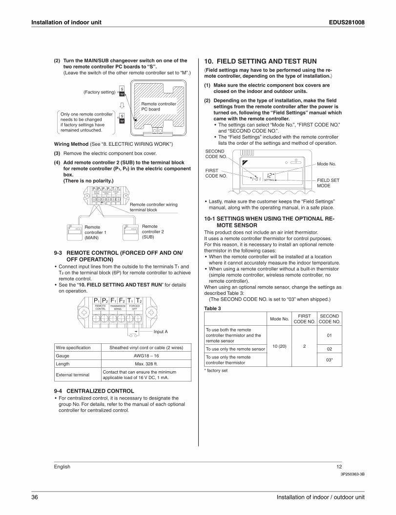
Turn the MAIN/SUB changeover switch on one of the (2)two remote controller PC boards to “S”.(Leave the switch of the other remote controller set to “M”.)
S
MS
SM(Factory setting)
Only one remote controller needs to be changed if factory settings have remained untouched.
Remote controller PC board
Wiring Method (See ‘‘8. ELECTRIC WIRING WORK’’)
Remove the electric component box cover.(3)
Add remote controller 2 (SUB) to the terminal block (4)for remote controller (P¹, P²) in the electric component box.(There is no polarity.)
Remote controller wiring terminal block
Remote controller 2(SUB)
Remote controller 1(MAIN)
1P 2P 1F 2F 1T 2TFORCED
OFFREMOTECONTRL
TRANSMISSIONWIRING
REMOTE CONTROL (FORCED OFF AND ON/9-3OFF OPERATION)
Connect input lines from the outside to the terminals T• ¹ and T² on the terminal block (6P) for remote controller to achieve remote control.See the “• 10. FIELD SETTING AND TEST RUN” for details on operation.
Input A
1P 2P 1F 2F 1T 2TFORCED
OFFREMOTECONTRL
TRANSMISSIONWIRING
Wire specifi cation Sheathed vinyl cord or cable (2 wires)
Gauge AWG18 – 16
Length Max. 328 ft.
External terminalContact that can ensure the minimum applicable load of 16 V DC, 1 mA.
CENTRALIZED CONTROL9-4For centralized control, it is necessary to designate the •group No. For details, refer to the manual of each optional controller for centralized control.
FIELD SETTING AND TEST RUN10. ⟨Field settings may have to be performed using the re-mote controller, depending on the type of installation.⟩
Make sure the electric component box covers are (1)closed on the indoor and outdoor units.
Depending on the type of installation, make the fi eld (2)settings from the remote controller after the power is turned on, following the “Field Settings” manual which came with the remote controller.
The settings can select “Mode No.”, “FIRST CODE NO.” •and “SECOND CODE NO.”.The “Field Settings” included with the remote controller •lists the order of the settings and method of operation.
SETTING
Mode No.
FIELD SET MODE
SECOND CODE NO.
FIRST CODE NO.
Lastly, make sure the customer keeps the “Field Settings” •manual, along with the operating manual, in a safe place.
SETTINGS WHEN USING THE OPTIONAL RE-10-1MOTE SENSOR
This product does not include an air inlet thermistor.It uses a remote controller thermistor for control purposes.For this reason, it is necessary to install an optional remote thermistor in the following cases:
When the remote controller will be installed at a location •where it cannot accurately measure the indoor temperature.When using a remote controller without a built-in thermistor •(simple remote controller, wireless remote controller, no remote controller).
When using an optional remote sensor, change the settings as described Table 3:
(The SECOND CODE NO. is set to “03” when shipped.)
Table 3
Mode No.FIRST
CODE NO.SECOND
CODE NO.
To use both the remote controller thermistor and the remote sensor
10 (20) 2
01
To use only the remote sensor 02
To use only the remote controller thermistor
03*
* factory set
36 Installation of indoor / outdoor unit
EDUS281008 Installation of indoor unit
2
3P250363-3B
13 English
REMOTE CONTROL SETTING10-2Forced off and ON/OFF operation should be selected by select-•ing the SECOND CODE NO. as shown in the table Table 4.
Table 4
External ON/OFF input Mode No.FIRST
CODE NO.SECOND
CODE NO.
Forced off12 (22) 1
01*
ON/OFF operation 02
* factory set
Input A of forced off and ON/OFF operation work as shown •in Table 5.
Table 5
Forced off ON/OFF operation
Input A “on” to force a stop (remote controller reception prohibited)
Unit operated by changing input A from “off” to “on”
Input A “off” to allow remote controller
Unit stopped by changing input A from “on” to “off”
SETTING THE FILTER SIGN DISPLAY INTERVAL10-3Explain the following to the customer if the fi lter dirt settings •have been changed.The fi lter sign display time is set to 2500 hours (equivalent •to 1 year’s use) when shipped.The settings can be changed to not display.•When installing the unit in a dusty place, set the fi lter sign •display time to shorter intervals (1,250 hours).Explain it to the customer that the fi lter needs to be cleaned •regularly to prevent clogging and also the time that is set.
Mode No. FIRST CODE NO.
SECONDCODE NO.
01 02
10 (20)
0 Filter dirt low high
1 (low/high)Displayed time(units: hours)
2500/1250
10000/5000
3 Filter sign display ON OFF
INSTALLATION OF THE OPTIONAL AIR FILTER10-4Purchase and install the air fi lter as in Table 6 .•
Table 6
Air fi lter
18 · 24 type FIL 48-61
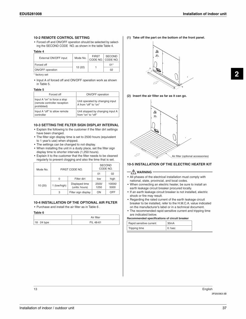
Take off the part on the bottom of the front panel.(1)
Insert the air fi lter as far as it can go.(2)
Air filter (optional accessories)
INSTALLATION OF THE ELECTRIC HEATER KIT10-5
WARNING
All phases of the electrical installation must comply with •national, state, provincial, and local codes.When connecting an electric heater, be sure to install an •earth leakage circuit breaker procured locally.If an earth leakage circuit breaker is not installed, electric •shock or fi re may result.Regarding the rated current of the earth leakage circuit •breaker to be installed, refer to the H.M.C.A. value indicated on the manufacturer’s label or in a technical document.The recommended rapid sensitive current and tripping time •are indicated below.
Recommended specifi cations of circuit breaker
Rapid sensitive current 30mA
Tripping time 0.1sec
Installation of indoor / outdoor unit 37
Installation of indoor unit EDUS281008
3P250363-3B
English 14
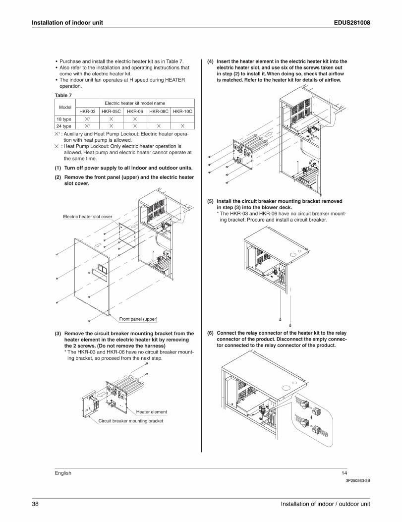
Purchase and install the electric heater kit as in Table 7.•Also refer to the installation and operating instructions that •come with the electric heater kit.The indoor unit fan operates at H speed during HEATER •operation.
Table 7
ModelElectric heater kit model name
HKR-03 HKR-05C HKR-06 HKR-08C HKR-10C
18 type 1
24 type 1
1 : Auxiliary and Heat Pump Lockout: Electric heater opera-tion with heat pump is allowed.
: Heat Pump Lockout: Only electric heater operation is allowed. Heat pump and electric heater cannot operate at the same time.
Turn off power supply to all indoor and outdoor units.(1)
Remove the front panel (upper) and the electric heater (2)slot cover.
Electric heater slot cover
Front panel (upper)
Remove the circuit breaker mounting bracket from the (3)heater element in the electric heater kit by removing the 2 screws. (Do not remove the harness)* The HKR-03 and HKR-06 have no circuit breaker mount-
ing bracket, so proceed from the next step.
Circuit breaker mounting bracket
Heater element
Insert the heater element in the electric heater kit into the (4)electric heater slot, and use six of the screws taken out in step (2) to install it. When doing so, check that airfl ow is matched. Refer to the heater kit for details of airfl ow.
Install the circuit breaker mounting bracket removed (5)in step (3) into the blower deck.* The HKR-03 and HKR-06 have no circuit breaker mount-
ing bracket; Procure and install a circuit breaker.
Connect the relay connector of the heater kit to the relay (6)connector of the product. Disconnect the empty connec-tor connected to the relay connector of the product.
38 Installation of indoor / outdoor unit
EDUS281008 Installation of indoor unit
2
3P250363-3B
15 English
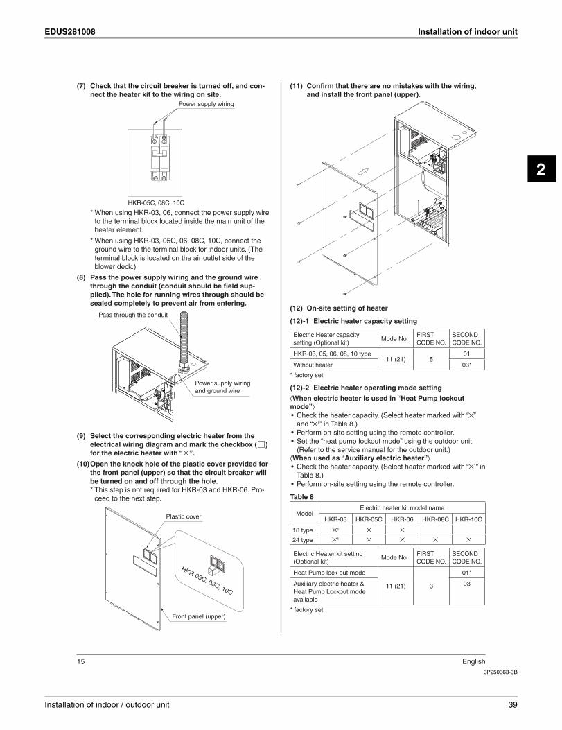
Check that the circuit breaker is turned off, and con-(7)nect the heater kit to the wiring on site.
Power supply wiring
HKR-05C, 08C, 10C
* When using HKR-03, 06, connect the power supply wire to the terminal block located inside the main unit of the heater element.
* When using HKR-03, 05C, 06, 08C, 10C, connect the ground wire to the terminal block for indoor units. (The terminal block is located on the air outlet side of the blower deck.)
Pass the power supply wiring and the ground wire (8)through the conduit (conduit should be fi eld sup-plied). The hole for running wires through should be sealed completely to prevent air from entering.
Pass through the conduit
Power supply wiring and ground wire
Select the corresponding electric heater from the (9)electrical wiring diagram and mark the checkbox ( ) for the electric heater with “ ”.
Open the knock hole of the plastic cover provided for (10)the front panel (upper) so that the circuit breaker will be turned on and off through the hole.* This step is not required for HKR-03 and HKR-06. Pro-
ceed to the next step.
Plastic cover
HKR-05C, 08C, 10C
Front panel (upper)
Confi rm that there are no mistakes with the wiring, (11)and install the front panel (upper).
On-site setting of heater (12)
Electric heater capacity setting(12) -1
Electric Heater capacity setting (Optional kit)
Mode No.FIRSTCODE NO.
SECONDCODE NO.
HKR-03, 05, 06, 08, 10 type11 (21) 5
01
Without heater 03*
* factory set
Electric heater operating mode setting(12) -2
⟨When electric heater is used in “Heat Pump lockout mode”⟩
Check the heater capacity. (Select heater marked with “• ”and “ 1” in Table 8.)Perform on-site setting using the remote controller.•Set the “heat pump lockout mode” using the outdoor unit. •(Refer to the service manual for the outdoor unit.)
⟨When used as “Auxiliary electric heater”⟩Check the heater capacity. (Select heater marked with “• 1” in Table 8.)Perform on-site setting using the remote controller.•
Table 8
ModelElectric heater kit model name
HKR-03 HKR-05C HKR-06 HKR-08C HKR-10C
18 type 1
24 type 1
Electric Heater kit setting (Optional kit)
Mode No.FIRSTCODE NO.
SECONDCODE NO.
Heat Pump lock out mode
11 (21) 3
01*
Auxiliary electric heater & Heat Pump Lockout mode available
03
* factory set
Installation of indoor / outdoor unit 39
Installation of indoor unit EDUS281008
3P250363-3B
English 16
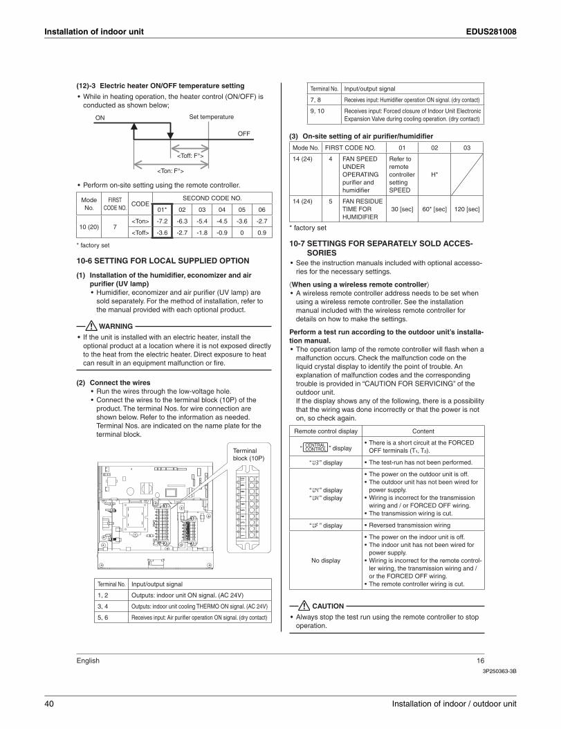
Electric heater ON/OFF temperature setting(12) -3
While in heating operation, the heater control (ON/OFF) is •conducted as shown below;
ON Set temperature
OFF
<Ton: F°>
<Toff: F°>
Perform on-site setting using the remote controller.•
ModeNo.
FIRSTCODE NO.
CODESECOND CODE NO.
01* 02 03 04 05 06
10 (20) 7<Ton> -7.2 -6.3 -5.4 -4.5 -3.6 -2.7
<Toff> -3.6 -2.7 -1.8 -0.9 0 0.9
* factory set
SETTING FOR LOCAL SUPPLIED OPTION10-6
Installation of the humidifi er, economizer and air (1)purifi er (UV lamp)
Humidifi er, economizer and air purifi er (UV lamp) are •sold separately. For the method of installation, refer to the manual provided with each optional product.
WARNING
If the unit is installed with an electric heater, install the •optional product at a location where it is not exposed directly to the heat from the electric heater. Direct exposure to heat can result in an equipment malfunction or fi re.
Connect the wires(2)Run the wires through the low-voltage hole.•Connect the wires to the terminal block (10P) of the •product. The terminal Nos. for wire connection are shown below. Refer to the information as needed. Terminal Nos. are indicated on the name plate for the terminal block.
Terminalblock (10P)
105
14
36
27
98
Terminal No. Input/output signal
1, 2 Outputs: indoor unit ON signal. (AC 24V)
3, 4 Outputs: indoor unit cooling THERMO ON signal. (AC 24V)
5, 6 Receives input: Air purifi er operation ON signal. (dry contact)
Terminal No. Input/output signal
7, 8 Receives input: Humidifi er operation ON signal. (dry contact)
9, 10 Receives input: Forced closure of Indoor Unit Electronic Expansion Valve during cooling operation. (dry contact)
On-site setting of air purifi er/humidifi er(3)
Mode No. FIRST CODE NO. 01 02 03
14 (24) 4 FAN SPEEDUNDEROPERATING purifi er and humidifi er
Refer to remotecontrollersettingSPEED
H*
14 (24) 5 FAN RESIDUE TIME FOR HUMIDIFIER
30 [sec] 60* [sec] 120 [sec]
* factory set
SETTINGS FOR SEPARATELY SOLD ACCES-10-7SORIES
See the instruction manuals included with optional accesso-•ries for the necessary settings.
⟨When using a wireless remote controller⟩A wireless remote controller address needs to be set when •using a wireless remote controller. See the installation manual included with the wireless remote controller for details on how to make the settings.
Perform a test run according to the outdoor unit’s installa-tion manual.
The operation lamp of the remote controller will fl ash when a •malfunction occurs. Check the malfunction code on the liquid crystal display to identify the point of trouble. An explanation of malfunction codes and the corresponding trouble is provided in “CAUTION FOR SERVICING” of the outdoor unit.If the display shows any of the following, there is a possibility that the wiring was done incorrectly or that the power is not on, so check again.
Remote control display Content
“ ” displayThere is a short circuit at the FORCED •OFF terminals (T¹, T²).
“ U3 ” display The test-run has not been performed. •
“ U4 ” display“ UH ” display
The power on the outdoor unit is off. •The outdoor unit has not been wired for •power supply.Wiring is incorrect for the transmission •wiring and / or FORCED OFF wiring.The transmission wiring is cut. •
“ UF ” display Reversed transmission wiring •
No display
The power on the indoor unit is off. •The indoor unit has not been wired for •power supply.Wiring is incorrect for the remote control- •ler wiring, the transmission wiring and / or the FORCED OFF wiring.The remote controller wiring is cut. •
CAUTION
Always stop the test run using the remote controller to stop •operation.
40 Installation of indoor / outdoor unit
EDUS281008 Installation of outdoor unit
2
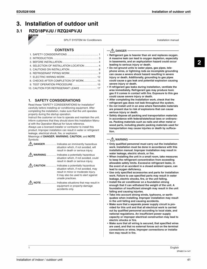
3. Installation of outdoor unit3.1 RZQ18PVJU / RZQ24PVJU
3PA60114-14Y
SPLIT SYSTEM Air Conditioners Installation manual
1 English
CONTENTS1. SAFETY CONSIDERATIONS ........................................... 12. INTRODUCTION ............................................................... 33. BEFORE INSTALLATION .................................................. 44. SELECTION OF INSTALLATION LOCATION ................... 45. CAUTIONS ON INSTALLATION ........................................ 86. REFRIGERANT PIPING WORK ....................................... 97. ELECTRIC WIRING WORK ............................................ 128. CHECKS AFTER COMPLETION OF WORK .................. 159. TEST OPERATION PROCEDURE ................................. 15
10. CAUTION FOR REFRIGERANT LEAKS ........................ 17
SAFETY CONSIDERATIONS1. Read these “SAFETY CONSIDERATIONS for Installation” carefully before installing air conditioning equipment. After completing the installation, make sure that the unit operates properly during the startup operation.Instruct the customer on how to operate and maintain the unit. Inform customers that they should store this Installation Manu-al with the Operation Manual for future reference.Always use a licensed installer or contractor to install this product. Improper installation can result in water or refrigerant leakage, electrical shock, fi re, or explosion.Meanings of DANGER, WARNING, CAUTION, and NOTESymbols:
DANGER ................ Indicates an imminently hazardous situation which, if not avoided, will result in death or serious injury.
WARNING .............. Indicates a potentially hazardous situation which, if not avoided, could result in death or serious injury.
CAUTION ............... Indicates a potentially hazardous situation which, if not avoided, may result in minor or moderate injury.It may also be used to alert against unsafe practices.
NOTE ..................... Indicates situations that may result in equipment or property-damage accidents only.
DANGER
Refrigerant gas is heavier than air and replaces oxygen. •A massive leak can lead to oxygen depletion, especially in basements, and an asphyxiation hazard could occur leading to serious injury or death.Do not ground units to water pipes, gas pipes, tele-•phone wires, or lightning rods as incomplete grounding can cause a severe shock hazard resulting in severe injury or death. Additionally, grounding to gas pipes could cause a gas leak and potential explosion causing severe injury or death.If refrigerant gas leaks during installation, ventilate the •area immediately. Refrigerant gas may produce toxic gas if it comes in contact with fi re. Exposure to this gas could cause severe injury or death.After completing the installation work, check that the •refrigerant gas does not leak throughout the system.Do not install unit in an area where fl ammable materials •are present due to risk of explosions that can cause serious injury or death.Safely dispose all packing and transportation materials •in accordance with federal/state/local laws or ordinanc-es. Packing materials such as nails and other metal or wood parts, including plastic packing materials used for transportation may cause injuries or death by suffoca-tion.
WARNING
Only qualifi ed personnel must carry out the installation •work. Installation must be done in accordance with this installation manual. Improper installation may result in water leakage, electric shock, or fi re.When installing the unit in a small room, take measures •to keep the refrigerant concentration from exceeding allowable safety limits. Excessive refrigerant leaks, in the event of an accident in a closed ambient space, can lead to oxygen defi ciency.Use only specifi ed accessories and parts for installation •work. Failure to use specifi ed parts may result in water leakage, electric shocks, fi re, or the unit falling.Install the air conditioner on a foundation strong •enough that it can withstand the weight of the unit. A foundation of insuffi cient strength may result in the unit falling and causing injuries.Take into account strong winds, typhoons, or earth-•quakes when installing. Improper installation may result in the unit falling and causing accidents.Make sure that a separate power supply circuit is pro-•vided for this unit and that all electrical work is carried out by qualifi ed personnel according to local state, and national regulations. An insuffi cient power supply capacity or improper electrical construction may lead to electric shocks or fi re.Make sure that all wiring is secured, that specifi ed wires •are used, and that no external forces act on the terminal connections or wires. Improper connections or installa-tion may result in fi re.
Installation of indoor / outdoor unit 41
Installation of outdoor unit EDUS281008
3PA60114-14Y
English 2
When wiring, position the wires so that the electrical •components box lid can be securely fastened. Improper positioning of the electrical components box lid may result in electric shocks, fi re, or the terminals overheating.Before touching electrical parts, turn off the unit.•Be sure to install a ground fault circuit interrupter if one •is not already available. This helps prevent electrical shocks or fi re.Securely fasten the outside unit terminal cover (panel). •If the terminal cover/panel is not installed properly, dust or water may enter the outside unit causing fi re or electric shock.When installing or relocating the system, keep the •refrigerant circuit free from substances other than the specifi ed refrigerant (R-410A) such as air. Any presence of air or other foreign substance in the refrigerant cir-cuit can cause an abnormal pressure rise or rupture, resulting in injury.Do not change the setting of the protection devices. If •the pressure switch, thermal switch, or other protection device is shorted and operated forcibly, or parts other than those specifi ed by Daikin are used, fi re or explo-sion may occur.
CAUTION
Do not touch the switch with wet fi ngers. Touching a •switch with wet fi ngers can cause electric shock.Do not allow children to play on or around the unit to •prevent injury.Do not touch the refrigerant pipes during and immedi-•ately after operation as the refrigerant pipes may be hot or cold, depending on the condition of the refrigerant fl owing through the refrigerant piping, compressor, and other refrigerant cycle parts. Your hands may suffer burns or frostbite if you touch the refrigerant pipes. To avoid injury, give the pipes time to return to normal temperature or, if you must touch them, be sure to wear proper gloves.Heat exchanger fi ns are sharp enough to cut.•To avoid injury wear glove or cover the fi ns when work-ing around them.Install drain piping to proper drainage. Improper drain •piping may result in water leakage and property dam-age.Insulate piping to prevent condensation.•Be careful when transporting the product.•Do not turn off the power immediately after stopping •operation. Always wait for at least 5 minutes before turning off the power. Otherwise, water leakage may occur.Do not use a charging cylinder. Using a charging cylin-•der may cause the refrigerant to deteriorate.Refrigerant R-410A in the system must be kept clean, •dry, and tight.(a) Clean and Dry -- Foreign materials (including mineral
oils such as SUNISO oil or moisture) should be prevented from getting into the system.
(b) Tight -- R-410A does not contain any chlorine, does not destroy the ozone layer, and does not reduce the earth’s protection again harmful ultraviolet radiation. R-410A can contribute to the greenhouse effect if it is released. Therefore take proper measures to check for the tightness of the refrigerant piping installation. Read the chapter Refrigerant Piping and follow the procedures.
Since R-410A is a blend, the required additional refriger-•ant must be charged in its liquid state. If the refrigerant is charged in a state of gas, its composition can change and the system will not work properly.The indoor unit is for R-410A. See the catalog for indoor •models that can be connected. Normal operation is not possible when connected to other units.Remote controller (wireless kit) transmitting distance •can be shorter than expected in rooms with electronic fl uorescent lamps (inverter or rapid start types). Install the indoor unit far away from fl uorescent lamps as much as possible.Indoor units are for indoor installation only. Outdoor •units can be installed either outdoors or indoors.Do not install the air conditioner in the following loca-•tions:(a) Where a mineral oil mist or oil spray or vapor is
produced, for example, in a kitchen. Plastic parts may deteriorate and fall off or result in
water leakage.(b) Where corrosive gas, such as sulfurous acid gas, is
produced. Corroding copper pipes or soldered parts may result
in refrigerant leakage.(c) Near machinery emitting electromagnetic waves. Electromagnetic waves may disturb the operation of
the control system and cause the unit to malfunc-tion.
(d) Where fl ammable gas may leak, where there is car-bon fi ber, or ignitable dust suspension in the air, or where volatile fl ammables such as thinner or gaso-line are handled. Operating the unit in such condi-tions can cause a fi re.
Take adequate measures to prevent the outside unit •from being used as a shelter by small animals. Small animals making contact with electrical parts can cause malfunctions, smoke, or fi re. Instruct the customer to keep the area around the unit clean.
NOTE
Install the power supply and control wires for the indoor •and outdoor units at least 3.5 feet away from televisions or radios to prevent image interference or noise.Depending on the radio waves, a distance of 3.5 feet may not be suffi cient to eliminate the noise.Dismantling the unit, treatment of the refrigerant, oil and •additional parts must be done in accordance with the relevant local, state, and national regulations.Do not use the following tools that are used with con-•ventional refrigerants: gauge manifold, charge hose, gas leak detector, reverse fl ow check valve, refrigerant charge base, vacuum gauge, or refrigerant recovery equipment.If the conventional refrigerant and refrigerator oil are •mixed in R-410A, the refrigerant may deteriorate.
42 Installation of indoor / outdoor unit
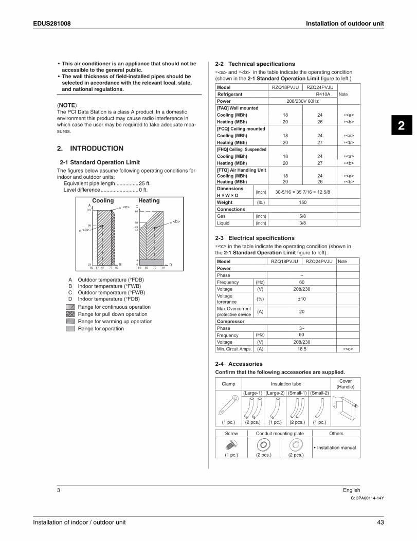
EDUS281008 Installation of outdoor unit
2
C: 3PA60114-14Y
3 English
This air conditioner is an appliance that should not be •accessible to the general public.The wall thickness of fi eld-installed pipes should be •selected in accordance with the relevant local, state, and national regulations.
⟨ ⟩The PCI Data Station is a class A product. In a domestic environment this product may cause radio interference in which case the user may be required to take adequate mea-sures.
INTRODUCTION2.
Standard peration imit2-1The fi gures below assume following operating conditions for indoor and outdoor units:
Equivalent pipe length ................25 ft.Level difference ..........................0 ft.
Cooling Heating
<b>
B
<c>A C
D
<a>
0
5
59
115
41
5050
43
70
95
81
50
2377
60
67 8257
A Outdoor temperature (°FDB) B Indoor temperature (°FWB) C Outdoor temperature (°FWB) D Indoor temperature (°FDB)
Range for continuous operation Range for pull down operation Range for warming up operation Range for operation
Technical specifi cations2-2∗<a> and ∗<b> in the table indicate the operating condition (shown i fi gure .)
Model RZQ18PVJU RZQ24PVJU
Refrigerant R410A
Power 208/230V 60Hz
[FAQ] Wall mountedCooling (MBh) ∗<a>
Heating (MBh) ∗<b>
[FCQ] Ceiling mountedCooling (MBh) ∗<a>
Heating (MBh) ∗<b>
[FHQ] Ceiling SuspendedCooling (MBh) ∗<a>
Heating (MBh) ∗<b>
[FTQ] Air Handling UnitCooling (MBh)Heating (MBh)
18
20
18
20
18
20
1820
24
26
24
27
24
27
2426
∗<a>∗<b>
Dimensions(inch) 30-5/16 × 35 7/16 × 12 5/8
H × W × DWeight (lb.) 150
ConnectionsGas (inch) 5/8
Liquid (inch) 3/8
Electrical specifi cations2-3∗<c> in the table indicate the operating condition (shown in the figure ).
Model RZQ18PVJU RZQ24PVJU
PowerPhase ~Frequency (Hz) 60
Voltage (V) 208/230
Voltagetorerance
(%) ±10
Max.Overcurrentprotective device
(A) 20
CompressorPhase 3~
Frequency (Hz) 60
Voltage (V) 208/230
Min. Circuit Amps. (A) 16.5 ∗<c>
Accessories2-4Confirm that the following accessories are supplied.
Clamp Insulation tubeCover
(Handle)(Large-1) (Large-2) (Small-1) (Small-2)
(1 pc.) (2 pcs.) (1 pc.) (2 pcs.) (1 pc.)
Screw Conduit mounting plate Others
Installation manual •
(1 pc.) (2 pcs.) (2 pcs.)
Installation of indoor / outdoor unit 43
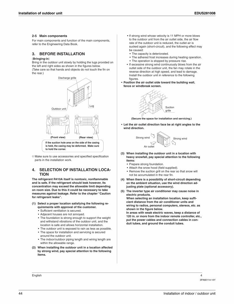
Installation of outdoor unit EDUS281008
3PA60114-14Y
English 4
Main components2-5For main components and function of the main components, refer to the Engineering Data Book.
BEFORE INSTALLATION3. ⟨Bringing-in⟩Bring in the outdoor unit slowly by holding the lugs provided on the left and right sides as shown in the fi gures below.(Take care so that hands and objects do not touch the fi n on the rear.)
Discharge grille
Outdoor unitLug
If the suction hole area on the side of the casing is held, the casing may be deformed. Make sure to hold the corner.
(Rear view)(Front view)
Make sure to use accessories and specifi ed specifi cation parts in the installation work.
SELECTION OF INSTALLATION LOCA-4. TION
The refrigerant R410A itself is nontoxic, nonfl ammable and is safe. If the refrigerant should leak however, its concentration may exceed the allowable limit depending on room size. Due to this it could be necessary to take measures against leakage. Refer to the chapter “Caution for refrigerant leaks”.
Select a proper location satisfying the following re-(1)quirements with approval of the customer.
Suffi cient ventilation is secured.•Adjacent houses are not annoyed.•The foundation is strong enough to support the weight •and withstand vibrations of the outdoor unit, and the location is safe and allows horizontal installation.The outdoor unit is exposed to rain as less as possible.•The space for installation and servicing is secured •around the outdoor unit.The indoor/outdoor piping length and wiring length are •within the allowable range.
When installing the outdoor unit in a location affected (2)by strong wind, pay special attention to the following items.
If strong wind whose velocity is or more blows •to the outdoor unit from the air outlet side, the air fl ow rate of the outdoor unit is reduced, the outlet air is sucked again (short-circuit), and the following effect may be caused:
The capacity is deteriorated.•The adhered frost increases during heating operation.•The operation is stopped by pressure rise.•
If excessive strong wind continuously blows from the air •outlet side of the outdoor unit, the fan may rotate in the reverse direction at high speed, and lead to damage. Install the outdoor unit in reference to the following fi gures.
Position the air outlet side toward the building wall, •fence or windbreak screen.
Suction grille
(Secure the space for installation and servicing.)
Let the air outlet direction face be at right angles to the •wind direction.
Strong windStrong wind
Air outlet
When installing the outdoor unit in a location with (3)heavy snowfall, pay special attention to the following items:
Prepare strong foundation.•Attach the snow hood ( ).•Remove the suction grill on the rear so that snow will •not be accumulated in the rear fi n.
When there is a possibility of short-circuit depending (4)on the ambient situation, use the wind direction ad-justing plate (optional accessory).
The inverter type air conditioner may cause noise in (5)electric products.When selecting an installation location, keep suffi -cient distance from the air conditioner units and wiring to radios, personal computers, stereos, etc. as shown in the fi gure below.In areas with weak electric waves, keep a distance of 120 in. or more from the indoor remote controller, etc., put the power cables and connection cables in con-duit tubes, and ground the conduit tubes.
44 Installation of indoor / outdoor unit
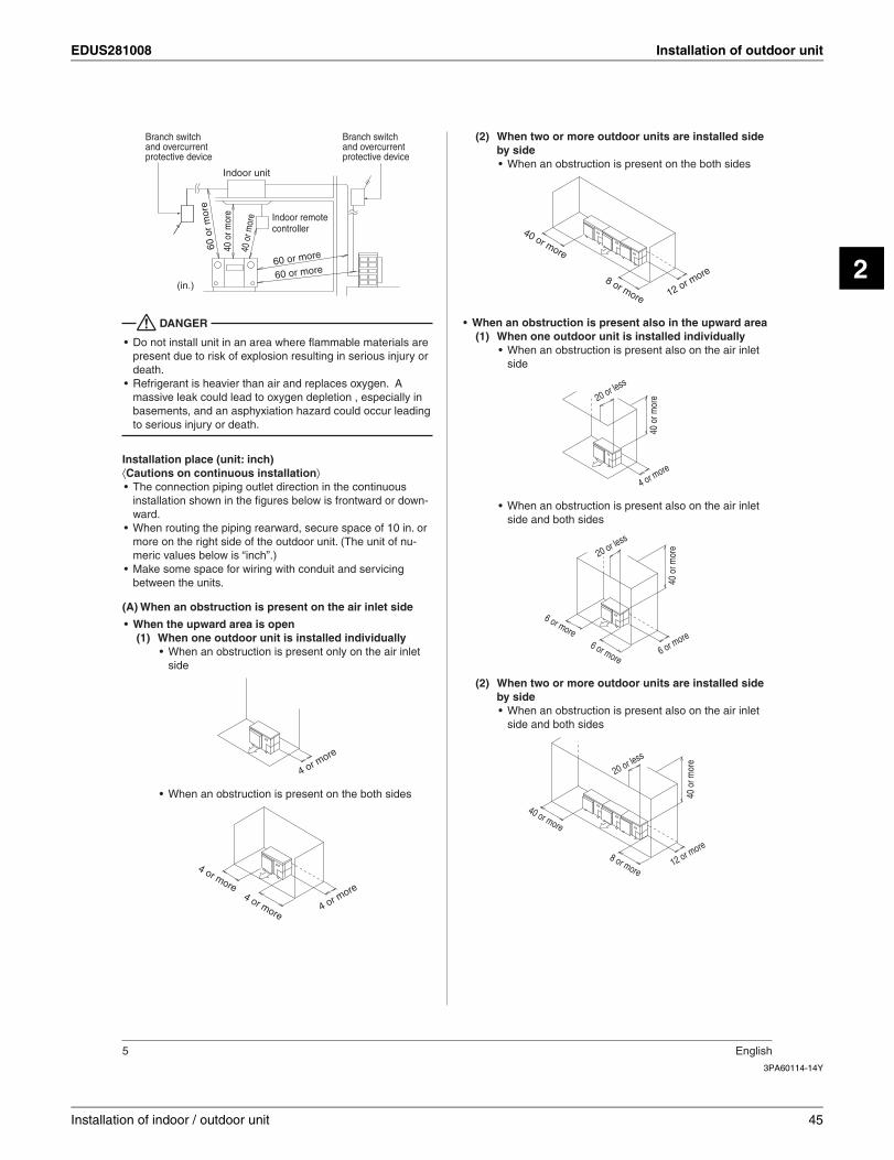
EDUS281008 Installation of outdoor unit
2
3PA60114-14Y
5 English
40 o
r mor
e
Branch switch and overcurrent protective device
Indoor remote controller
60 or more
60 o
r m
ore
40 o
r mor
e
Branch switch and overcurrent protective device
60 or more
Indoor unit
(in.)
DANGER
Do not install unit in an area where fl ammable materials are •present due to risk of explosion resulting in serious injury or death.Refrigerant is heavier than air and replaces oxygen. A •massive leak could lead to oxygen depletion , especially in basements, and an asphyxiation hazard could occur leading to serious injury or death.
Installation place (unit: inch)⟨Cautions on continuous installation⟩
The connection piping outlet direction in the continuous •installation shown in the fi gures below is frontward or down-ward.When routing the piping rearward, secure space of 10 in. or •more on the right side of the outdoor unit. (The unit of nu-meric values below is “inch”.)Make some space for wiring with conduit and servicing •between the units.
(A) When an obstruction is present on the air inlet side
When the upward area is open•When one outdoor unit is installed individually(1)
When an obstruction is present only on the air inlet •side
4 or more
When an obstruction is present on the both sides•
4 or more4 or m
ore
4 or more
When two or more outdoor units are installed side (2)by side
When an obstruction is present on the both sides•
40 or more
12 or more8 or more
When an obstruction is present also in the upward area•When one outdoor unit is installed individually(1)
When an obstruction is present also on the air inlet •side
20 or less
40 o
r mor
e
4 or more
When an obstruction is present also on the air inlet •side and both sides
6 or more6 or more
20 or less
6 or more
40 o
r mor
eWhen two or more outdoor units are installed side (2)by side
When an obstruction is present also on the air inlet •side and both sides
20 or less
8 or more
40 or more
12 or more
40 o
r mor
e
Installation of indoor / outdoor unit 45
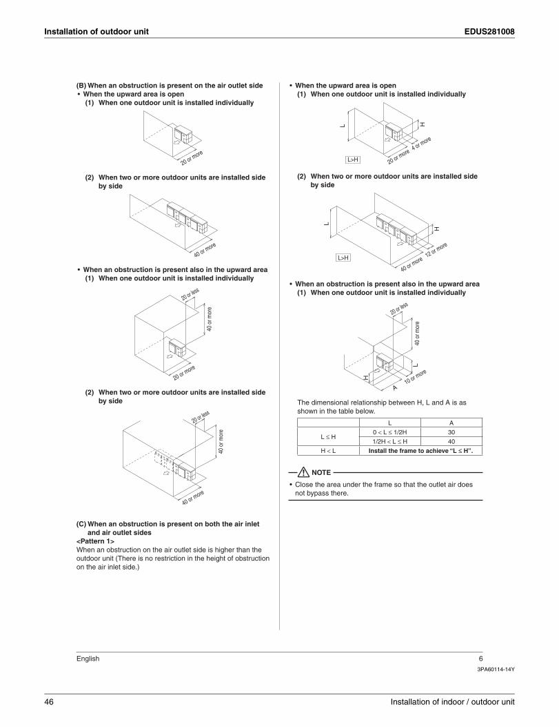
Installation of outdoor unit EDUS281008
3PA60114-14Y
English 6
(B) When an obstruction is present on the air outlet sideWhen the upward area is open•
When one outdoor unit is installed individually(1)
20 or more
When two or more outdoor units are installed side (2)by side
40 or more
When an obstruction is present also in the upward area•When one outdoor unit is installed individually(1)
20 or less
20 or more
40 o
r mor
e
When two or more outdoor units are installed side (2)by side
40 o
r mor
e
40 or more
20 or less
(C) When an obstruction is present on both the air inlet and air outlet sides
<Pattern 1>When an obstruction on the air outlet side is higher than the outdoor unit (There is no restriction in the height of obstruction on the air inlet side.)
When the upward area is open•When one outdoor unit is installed individually(1)
L
4 or more
H
20 or moreL>H
When two or more outdoor units are installed side (2)by side
12 or more
H
L
40 or moreL>H
When an obstruction is present also in the upward area•When one outdoor unit is installed individually(1)
L
A
20 or less
40 o
r mor
e
10 or moreH
The dimensional relationship between H, L and A is as shown in the table below.
L A
L ≤ H0 < L ≤ 1/2H 30
1/2H < L ≤ H 40
H < L Install the frame to achieve “L ≤ H”.
NOTE
Close the area under the frame so that the outlet air does •not bypass there.
46 Installation of indoor / outdoor unit
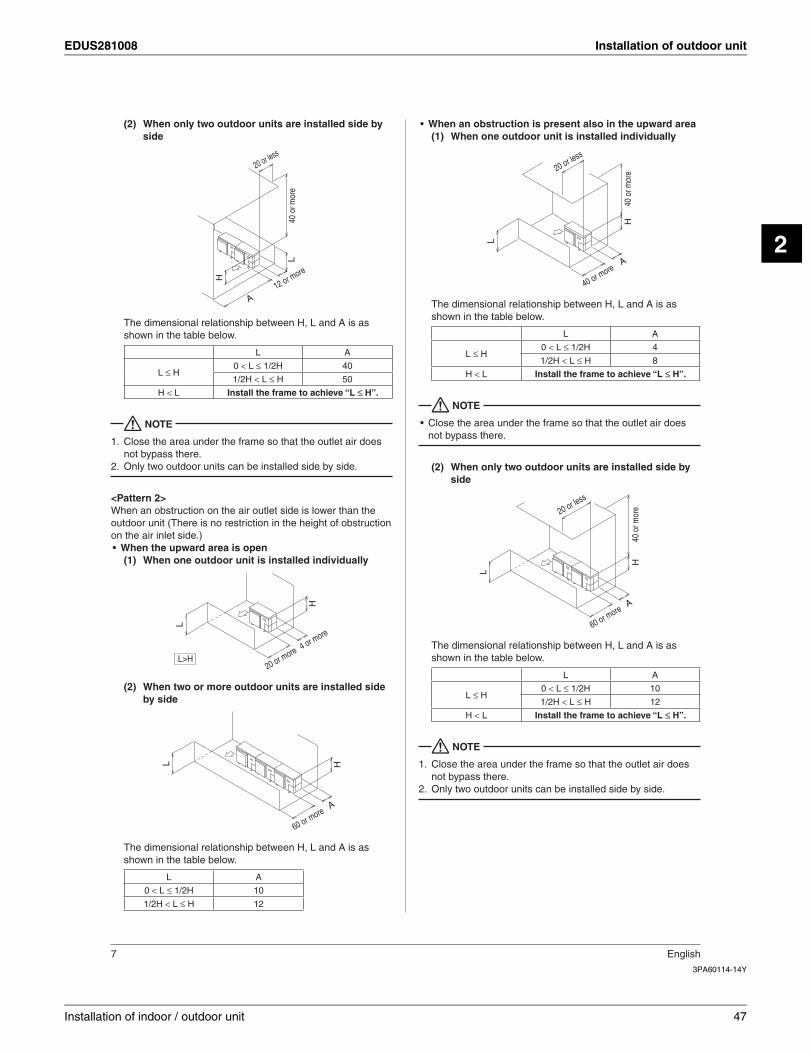
EDUS281008 Installation of outdoor unit
2
3PA60114-14Y
7 English
When only two outdoor units are installed side by (2)side
A
H
L
20 or less
12 or more
40 o
r mor
e
The dimensional relationship between H, L and A is as shown in the table below.
L A
L ≤ H0 < L ≤ 1/2H 40
1/2H < L ≤ H 50
H < L Install the frame to achieve “L ≤ H”.
NOTE
Close the area under the frame so that the outlet air does 1. not bypass there.Only two outdoor units can be installed side by side.2.
<Pattern 2>When an obstruction on the air outlet side is lower than the outdoor unit (There is no restriction in the height of obstruction on the air inlet side.)
When the upward area is open•When one outdoor unit is installed individually(1)
4 or more
20 or more
H
L
L>H
When two or more outdoor units are installed side (2)by side
L
60 or more
H
A
The dimensional relationship between H, L and A is as shown in the table below.
L A
0 < L ≤ 1/2H 10
1/2H < L ≤ H 12
When an obstruction is present also in the upward area•When one outdoor unit is installed individually(1)
L
40 o
r mor
e
40 or more
20 or less
H
A
The dimensional relationship between H, L and A is as shown in the table below.
L A
L ≤ H0 < L ≤ 1/2H 4
1/2H < L ≤ H 8
H < L Install the frame to achieve “L ≤ H”.
NOTE
Close the area under the frame so that the outlet air does •not bypass there.
When only two outdoor units are installed side by (2)side
60 or more
20 or less
H
L
A
40 o
r mor
eThe dimensional relationship between H, L and A is as shown in the table below.
L A
L ≤ H0 < L ≤ 1/2H 10
1/2H < L ≤ H 12
H < L Install the frame to achieve “L ≤ H”.
NOTE
Close the area under the frame so that the outlet air does 1. not bypass there.Only two outdoor units can be installed side by side.2.
Installation of indoor / outdoor unit 47
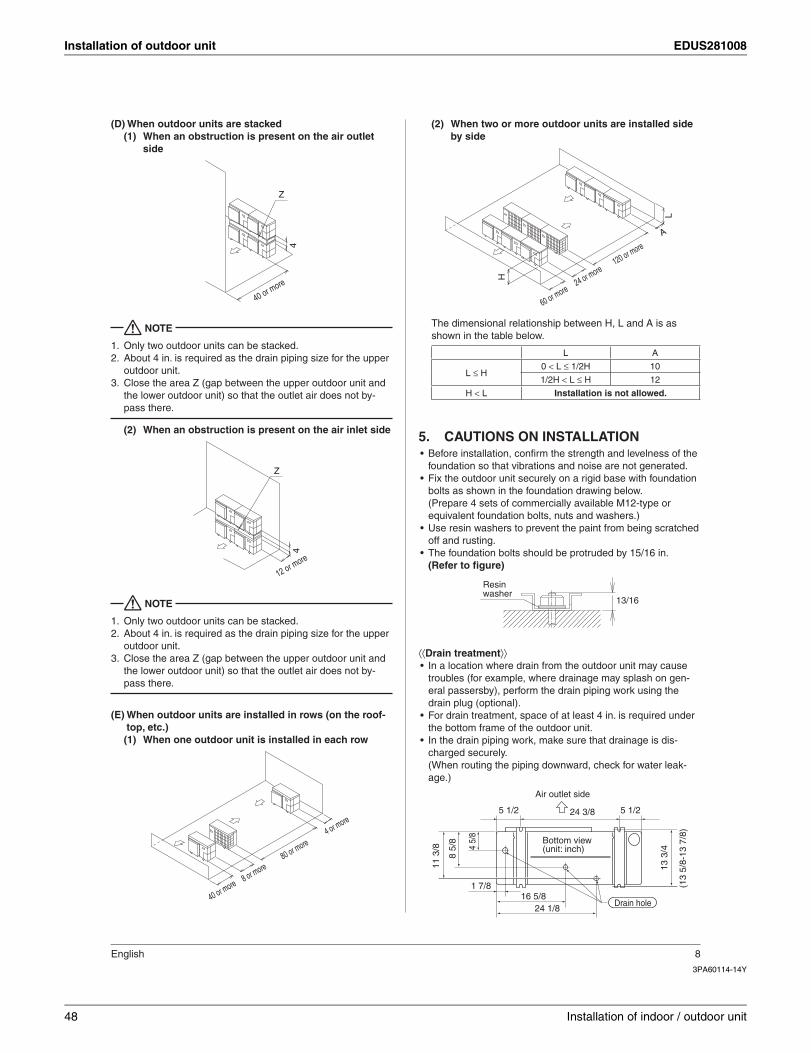
Installation of outdoor unit EDUS281008
3PA60114-14Y
English 8
(D) When outdoor units are stackedWhen an obstruction is present on the air outlet (1)side
4
Z
40 or more
NOTE
Only two outdoor units can be stacked.1. About 4 in. is required as the drain piping size for the upper 2. outdoor unit.Close the area Z (gap between the upper outdoor unit and 3. the lower outdoor unit) so that the outlet air does not by-pass there.
When an obstruction is present on the air inlet side(2)
4
Z
12 or more
NOTE
Only two outdoor units can be stacked.1. About 4 in. is required as the drain piping size for the upper 2. outdoor unit.Close the area Z (gap between the upper outdoor unit and 3. the lower outdoor unit) so that the outlet air does not by-pass there.
(E) When outdoor units are installed in rows (on the roof-top, etc.)
When one outdoor unit is installed in each row(1)
4 or more
8 or more80 or more
40 or more
When two or more outdoor units are installed side (2)by side
A
L
60 or more24 or more
120 or more
H
The dimensional relationship between H, L and A is as shown in the table below.
L A
L ≤ H0 < L ≤ 1/2H 10
1/2H < L ≤ H 12
H < L Installation is not allowed.
CAUTIONS ON INSTALLATION5. Before installation, confi rm the strength and levelness of the •foundation so that vibrations and noise are not generated.Fix the outdoor unit securely on a rigid base with foundation •bolts as shown in the foundation drawing below.(Prepare 4 sets of commercially available M12-type or equivalent foundation bolts, nuts and washers.)Use resin washers to prevent the paint from being scratched •off and rusting.The foundation bolts should be protruded by 15/16 in.•(Refer to fi gure)
13/16
Resinwasher
⟨⟨Drain treatment⟩⟩In a location where drain from the outdoor unit may cause •troubles (for example, where drainage may splash on gen-eral passersby), perform the drain piping work using the drain plug (optional).For drain treatment, space of at least 4 in. is required under •the bottom frame of the outdoor unit.In the drain piping work, make sure that drainage is dis-•charged securely.(When routing the piping downward, check for water leak-age.)
5 1/2
1 7/8
5 1/224 3/8
Air outlet side
(13
5/8-
13 7
/8)
13 3
/4
11 3
/8
8 5/
8
4 5/
8
Bottom view (unit: inch)
Drain hole16 5/8
24 1/8
48 Installation of indoor / outdoor unit
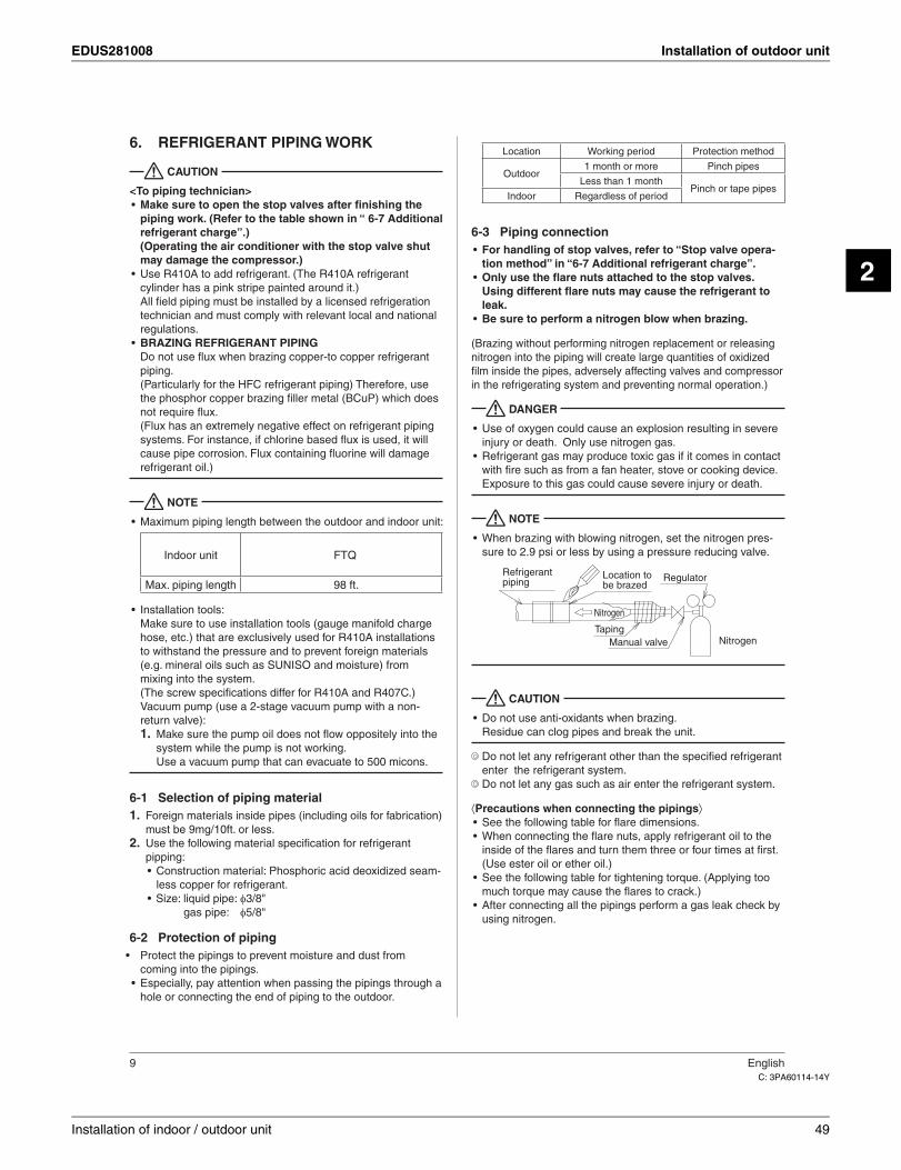
EDUS281008 Installation of outdoor unit
2
C: 3PA60114-14Y
9 English
REFRIGERANT PIPING WORK6.
CAUTION
<To piping technician>Make sure to open the stop valves after fi nishing the •piping work. (Refer to the table shown in “ 6-7 Additional refrigerant charge”.)(Operating the air conditioner with the stop valve shut may damage the compressor.)Use R410A to add refrigerant. (The R410A refrigerant •cylinder has a pink stripe painted around it.)All fi eld piping must be installed by a licensed refrigeration technician and must comply with relevant local and national regulations.BRAZING REFRIGERANT PIPING•Do not use fl ux when brazing copper-to copper refrigerant piping.(Particularly for the HFC refrigerant piping) Therefore, use the phosphor copper brazing fi ller metal (BCuP) which does not require fl ux.(Flux has an extremely negative effect on refrigerant piping systems. For instance, if chlorine based fl ux is used, it will cause pipe corrosion. Flux containing fl uorine will damage refrigerant oil.)
NOTE
Maximum piping length between the outdoor and indoor unit:•
Location Working period Protection method
Outdoor1 month or more Pinch pipes
Less than 1 monthPinch or tape pipes
Indoor Regardless of period
Piping connection6-3For handling of stop valves, refer to “Stop valve opera-•tion method” in “6-7 Additional refrigerant charge”.Only use the fl are nuts attached to the stop valves.•Using different fl are nuts may cause the refrigerant to leak.Be sure to perform a nitrogen blow when brazing.•
(Brazing without performing nitrogen replacement or releasing nitrogen into the piping will create large quantities of oxidized fi lm inside the pipes, adversely affecting valves and compressor in the refrigerating system and preventing normal operation.)
DANGER
Use of oxygen could cause an explosion resulting in severe •injury or death. Only use nitrogen gas.Refrigerant gas may produce toxic gas if it comes in contact •with fi re such as from a fan heater, stove or cooking device. Exposure to this gas could cause severe injury or death.
NOTE
When brazing with blowing nitrogen, set the nitrogen pres-•sure to 2.9 psi or less by using a pressure reducing valve.
Location to be brazed
Taping
Refrigerant piping
Nitrogen
Regulator
Manual valve Nitrogen
CAUTION
Do not use anti-oxidants when brazing.•Residue can clog pipes and break the unit.
Do not let any refrigerant other than the specifi ed refrigerant enter the refrigerant system.
Do not let any gas such as air enter the refrigerant system.
⟨Precautions when connecting the pipings⟩See the following table for fl are dimensions.•When connecting the fl are nuts, apply refrigerant oil to the •inside of the fl ares and turn them three or four times at fi rst. (Use ester oil or ether oil.)See the following table for tightening torque. (Applying too •much torque may cause the fl ares to crack.)After connecting all the pipings perform a gas leak check by •using nitrogen.
Indoor unit FTQ
Max. piping length 98 ft.
Installation tools:•Make sure to use installation tools (gauge manifold charge hose, etc.) that are exclusively used for R410A installations to withstand the pressure and to prevent foreign materials (e.g. mineral oils such as SUNISO and moisture) from mixing into the system.(The screw specifi cations differ for R410A and R407C.)Vacuum pump (use a 2-stage vacuum pump with a non-return valve):
Make sure the pump oil does not fl ow oppositely into the 1. system while the pump is not working.Use a vacuum pump can evacuate to .
Selection of piping material6-1Foreign materials inside pipes (including oils for fabrication) 1. must be 9mg/10ft. or less.Use the following material specifi cation for refrigerant 2. pipping:
Construction material: Phosphoric acid deoxidized seam-•less copper for refrigerant.Size: liquid pipe: • 3/8" gas pipe: 5/8"
Protection of piping6-2Protect the pipings to prevent moisture and dust from •coming into the pipings.Especially, pay attention when passing the pipings through a •hole or connecting the end of piping to the outdoor.
Installation of indoor / outdoor unit 49
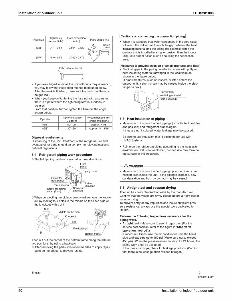
Installation of outdoor unit EDUS281008
3PA60114-14Y
English 10
Pipe sizeTightening
torque (ft·lbf)Flare dimension
A (in.)Flare shape (in.)
φ3/8” 24.1 - 29.4 0.504 - 0.520
A45°±
2°
90°±
2°
R0.016~0.031
φ5/8” 45.6 - 55.6 0.760 - 0.776
Ester oil or ether oil
If you are obliged to install the unit without a torque wrench, •you may follow the installation method mentioned below.After the work is fi nished, make sure to check that there is no gas leak.When you keep on tightening the fl are nut with a spanner, •there is a point where the tightening torque suddenly in-creases.From that position, further tighten the fl are nut the angle shown below.
Pipe sizeTightening angle
(Guideline)Recommended arm length of tool (in.)
φ3/8” 60°~90° Approx. 7 7/8
φ5/8” 30°~60° Approx. 11 13/16
Disposal requirementsDismantling of the unit, treatment of the refrigerant, oil and eventual other parts should be comply the relevant local and national regulations.
Refrigerant piping work procedure6-4The fi eld piping can be connected in three directions.
Piping cover
Screw for front panel
Screw for piping cover (front)
Front panel
Lateral directionFront direction
Downward direction
When connecting the pipings downward, remove the knock-out by making four holes in the middle on the each side of the knockout with a drill.
Field pipings
Bottom frame
Knockout
Drill
Slit
Middle on the side
Slit
Then cut out the corner of the bottom frame along the slits (in two positions) by using a hacksaw.
After removing the parts, it is recommended to apply repair paint on the edges, to prevent rusting.
Cautions on connecting the connection piping
When it is expected that water condensed in the stop valve •will reach the indoor unit through the gap between the heat insulating material and the piping (for example, when the outdoor unit is installed in a higher position than the indoor unit), take proper action such as caulking the connection area.
[Measures to prevent invasion of small creatures and litter]Block all gaps in the piping penetration areas with putty or •heat insulating material (arranged in the local fi eld) as shown in the fi gure below.(If small creatures, such as insects, or litter, enters the outdoor unit, a short-circuit may be caused inside the elec-tric parts box.)
Putty or heat insulating material ( )
Heat insulation of piping6-5Make sure to insulate the fi eld pipings (on both the liquid line •and gas line) and refrigerant branching kit.If they are not insulated, water leakage may be caused.
.
Reinforce the refrigerant piping according to the installation •environment. If it is not reinforced, condensate may form on the surface of the insulation.
WARNING
Make sure to insulate the fi eld piping up to the piping con-•nection area inside the unit. If the piping is exposed, dew condensation and burn by contact may be caused.
Airtight test and vacuum drying6-6The unit has been checked for leaks by the manufacturer.Confi rm that the valves are fi rmly closed before airtight test or vacuumdrying.To prevent entry of any impurities and insure suffi cient pres-sure resistance, always use the special tools dedicated for R410A.
Perform the following inspections securely after the piping work.
Airtight test• - Make sure to use nitrogen gas. (For the service port position, refer to the fi gure in “Stop valve operation method”.)[Procedure] Pressurize the air conditioner from the liquid pipe and gas pipe up to 450 psi (Make sure not to exceed 450 psi). When the pressure does not drop for 24 hours, the piping work shall be accepted. If the pressure drops, check for leakage positions. (Confi rm that there is no leakage, then release nitrogen.)
50 Installation of indoor / outdoor unit
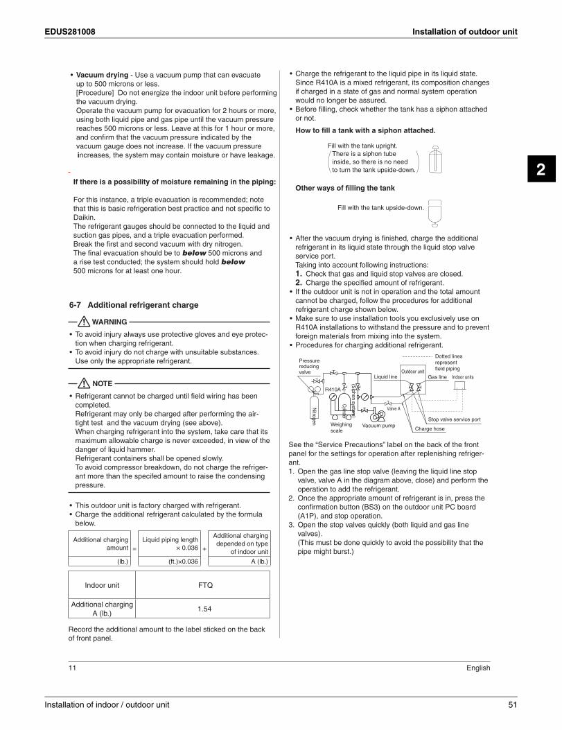
EDUS281008 Installation of outdoor unit
2
11 English
Vacuum drying• - Use a vacuum pump can evacuate up to[Procedure]
Additional refrigerant charge6-7
WARNING
To avoid injury always use protective gloves and eye protec-•tion when charging refrigerant.To avoid injury do not charge with unsuitable substances. •Use only the appropriate refrigerant.
NOTE
Refrigerant cannot be charged until fi eld wiring has been •completed.Refrigerant may only be charged after performing the air-tight test and the vacuum drying (see above).When charging refrigerant into the system, take care that its maximum allowable charge is never exceeded, in view of the danger of liquid hammer.Refrigerant containers shall be opened slowly.To avoid compressor breakdown, do not charge the refriger-ant more than the specifed amount to raise the condensing pressure.
This outdoor unit is factory charged with refrigerant.•Charge the additional refrigerant calculated by the formula •below.
Additional charging amount =
Liquid piping length × 0.036 +
Additional charging depended on type
of indoor unit
(lb.) (ft.)×0.036 A (lb.)
Indoor unit FTQ
Additional charging A (lb.)
1.54
Record the additional amount to the label sticked on the back of front panel.
Charge the refrigerant to the liquid pipe in its liquid state. •Since R410A is a mixed refrigerant, its composition changes if charged in a state of gas and normal system operation would no longer be assured.Before fi lling, check whether the tank has a siphon attached •or not.
How to fi ll a tank with a siphon attached.
There is a siphon tubeinside, so there is no needto turn the tank upside-down.
Fill with the tank upright.
Other ways of fi lling the tank
Fill with the tank upside-down.
After the vacuum drying is fi nished, charge the additional •refrigerant in its liquid state through the liquid stop valve service port.Taking into account following instructions:
Check that gas and liquid stop valves are closed.1. Charge the specifi ed amount of refrigerant.2.
If the outdoor unit is not in operation and the total amount •cannot be charged, follow the procedures for additional refrigerant charge shown below.Make sure to use installation tools you exclusively use on •R410A installations to withstand the pressure and to prevent foreign materials from mixing into the system.Procedures for charging additional refrigerant.•
Nitrogen
Dotted lines represent field piping
Cylinder
Stop valve service portVacuum pumpWeighing
scale Charge hose
R410A
Pressure reducing valve Outdoor unit
Indoor unitsLiquid line Gas line
(Siphon system
)
Valve A
See the “Service Precautions” label on the back of the front panel for the settings for operation after replenishing refriger-ant.
Open the gas line stop valve (leaving the liquid line stop 1. valve, valve A in the diagram above, close) and perform the operation to add the refrigerant.Once the appropriate amount of refrigerant is in, press the 2. confi rmation button (BS3) on the outdoor unit PC board (A1P), and stop operation.Open the stop valves quickly (both liquid and gas line 3. valves).(This must be done quickly to avoid the possibility that the pipe might burst.)
Installation of indoor / outdoor unit 51
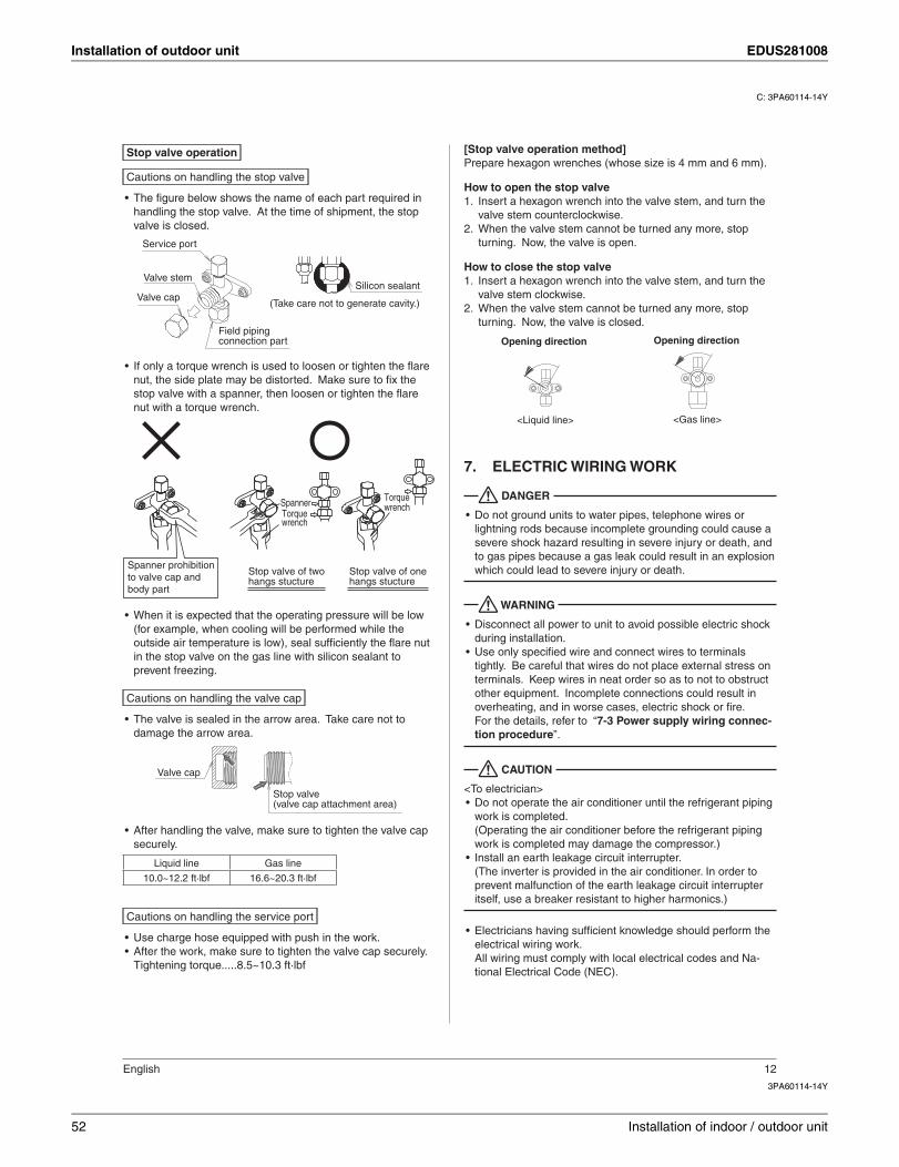
Installation of outdoor unit EDUS281008
C: 3PA60114-14Y
3PA60114-14Y
English 12
Stop valve operation
Cautions on handling the stop valve
The fi gure below shows the name of each part required in •handling the stop valve. At the time of shipment, the stop valve is closed.
Valve cap
Service port
Field piping connection part
Valve stemSilicon sealant
(Take care not to generate cavity.)
If only a torque wrench is used to loosen or tighten the fl are •nut, the side plate may be distorted. Make sure to fi x the stop valve with a spanner, then loosen or tighten the fl are nut with a torque wrench.
Stop valve of twohangs stucture
Stop valve of onehangs stucture
Torque wrench
Torquewrench
Spanner
Spanner prohibition to valve cap and body part
When it is expected that the operating pressure will be low •(for example, when cooling will be performed while the outside air temperature is low), seal suffi ciently the fl are nut in the stop valve on the gas line with silicon sealant to prevent freezing.
Cautions on handling the valve cap
The valve is sealed in the arrow area. Take care not to •damage the arrow area.
Valve cap
Stop valve (valve cap attachment area)
After handling the valve, make sure to tighten the valve cap •securely.
Liquid line Gas line
10.0~12.2 ft·lbf 16.6~20.3 ft·lbf
Cautions on handling the service port
Use charge hose equipped with push in the work.•After the work, make sure to tighten the valve cap securely.•Tightening torque.....8.5~10.3 ft·lbf
[Stop valve operation method]Prepare hexagon wrenches (whose size is 4 mm and 6 mm).
How to open the stop valveInsert a hexagon wrench into the valve stem, and turn the 1. valve stem counterclockwise.When the valve stem cannot be turned any more, stop 2. turning. Now, the valve is open.
How to close the stop valveInsert a hexagon wrench into the valve stem, and turn the 1. valve stem clockwise.When the valve stem cannot be turned any more, stop 2. turning. Now, the valve is closed.
<Liquid line> <Gas line>
Opening direction Opening direction
ELECTRIC WIRING WORK7.
DANGER
Do not ground units to water pipes, telephone wires or •lightning rods because incomplete grounding could cause a severe shock hazard resulting in severe injury or death, and to gas pipes because a gas leak could result in an explosion which could lead to severe injury or death.
WARNING
Disconnect all power to unit to avoid possible electric shock •during installation.Use only specifi ed wire and connect wires to terminals •tightly. Be careful that wires do not place external stress on terminals. Keep wires in neat order so as to not to obstruct other equipment. Incomplete connections could result in overheating, and in worse cases, electric shock or fi re.For the details, refer to “7-3 Power supply wiring connec-tion procedure”.
CAUTION
<To electrician>Do not operate the air conditioner until the refrigerant piping •work is completed.(Operating the air conditioner before the refrigerant piping work is completed may damage the compressor.)Install an earth leakage circuit interrupter.•(The inverter is provided in the air conditioner. In order to prevent malfunction of the earth leakage circuit interrupter itself, use a breaker resistant to higher harmonics.)
Electricians having suffi cient knowledge should perform the •electrical wiring work.All wiring must comply with local electrical codes and Na-tional Electrical Code (NEC).
52 Installation of indoor / outdoor unit
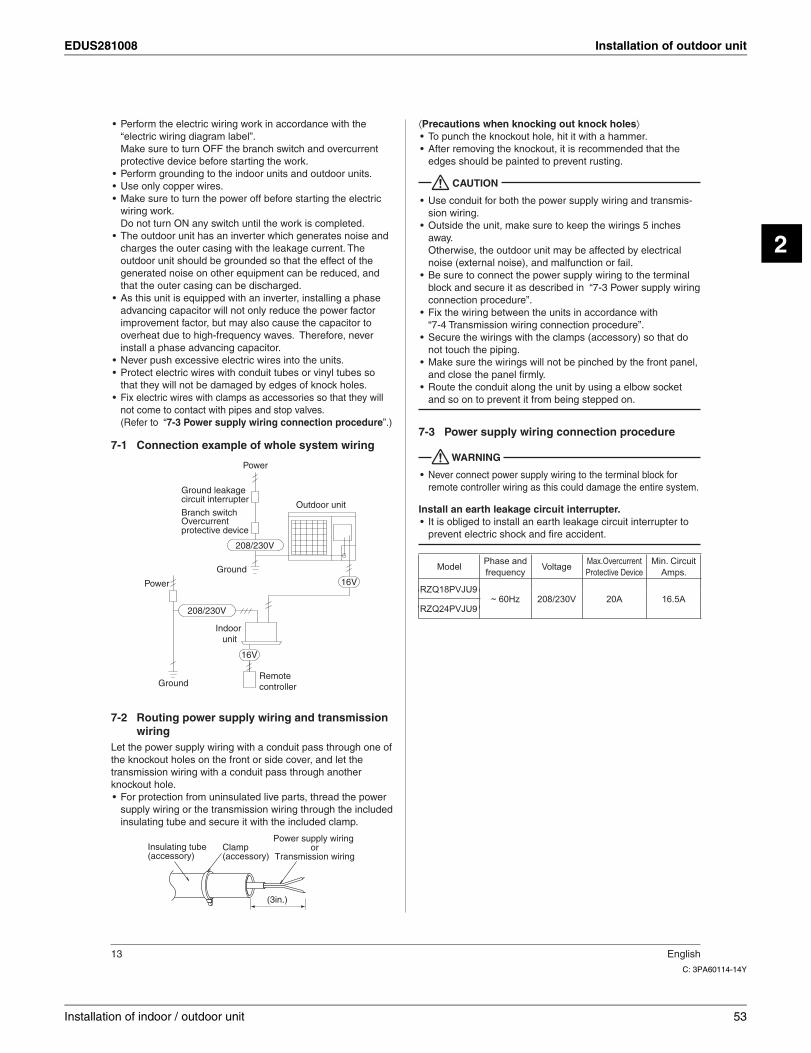
EDUS281008 Installation of outdoor unit
2
C: 3PA60114-14Y
13 English
Perform the electric wiring work in accordance with the •“electric wiring diagram label”.Make sure to turn OFF the branch switch and overcurrent protective device before starting the work.Perform grounding to the indoor units and outdoor units.•Use only copper wires.•Make sure to turn the power off before starting the electric •wiring work.Do not turn ON any switch until the work is completed.The outdoor unit has an inverter which generates noise and •charges the outer casing with the leakage current. The outdoor unit should be grounded so that the effect of the generated noise on other equipment can be reduced, and that the outer casing can be discharged.As this unit is equipped with an inverter, installing a phase •advancing capacitor will not only reduce the power factor improvement factor, but may also cause the capacitor to overheat due to high-frequency waves. Therefore, never install a phase advancing capacitor.Never push excessive electric wires into the units.•Protect electric wires with conduit tubes or vinyl tubes so •that they will not be damaged by edges of knock holes.Fix electric wires with clamps as accessories so that they will •not come to contact with pipes and stop valves.(Refer to “7-3 Power supply wiring connection procedure”.)
Connection example of whole system wiring7-1
Power
Remote controller
Indoor unit
Ground
Power
Ground
Outdoor unit
16V
208/230V
208/230V
16V
leakage circuit interrupter
Overcurrent protective device
Branch switch
Routing power supply wiring and transmission 7-2wiring
Let the power supply wiring with a conduit pass through one of the knockout holes on the front or side cover, and let the transmission wiring with a conduit pass through another knockout hole.
For protection from uninsulated live parts, thread the power •supply wiring or the transmission wiring through the included insulating tube and secure it with the included clamp.
Insulating tube(accessory)
Clamp(accessory)
Power supply wiring or
Transmission wiring
(3in.)
⟨Precautions when knocking out knock holes⟩To punch the knockout hole, hit it with a hammer.•After removing the knockout, it is recommended that the •edges should be painted to prevent rusting.
CAUTION
Use conduit for both the power supply wiring and transmis-•sion wiring.Outside the unit, make sure to keep the wirings 5 inches •away.Otherwise, the outdoor unit may be affected by electrical noise (external noise), and malfunction or fail.Be sure to connect the power supply wiring to the terminal •block and secure it as described in “7-3 Power supply wiring connection procedure”.Fix the wiring between the units in accordance with •“7-4 Transmission wiring connection procedure”.Secure the wirings with the clamps (accessory) so that do •not touch the piping.Make sure the wirings will not be pinched by the front panel, •and close the panel fi rmly.Route the conduit along the unit by using a elbow socket •and so on to prevent it from being stepped on.
Power supply wiring connection procedure7-3
WARNING
Never connect power supply wiring to the terminal block for •remote controller wiring as this could damage the entire system.
Install an earth leakage circuit interrupter.It is obliged to install an earth leakage circuit interrupter to •prevent electric shock and fi re accident.
ModelPhase and frequency
VoltageMax.OvercurrentProtective Device
Min. Circuit Amps.
RZQ18PVJU~ 60Hz 208/230V 20A 16.5A
RZQ24PVJU
Installation of indoor / outdoor unit 53
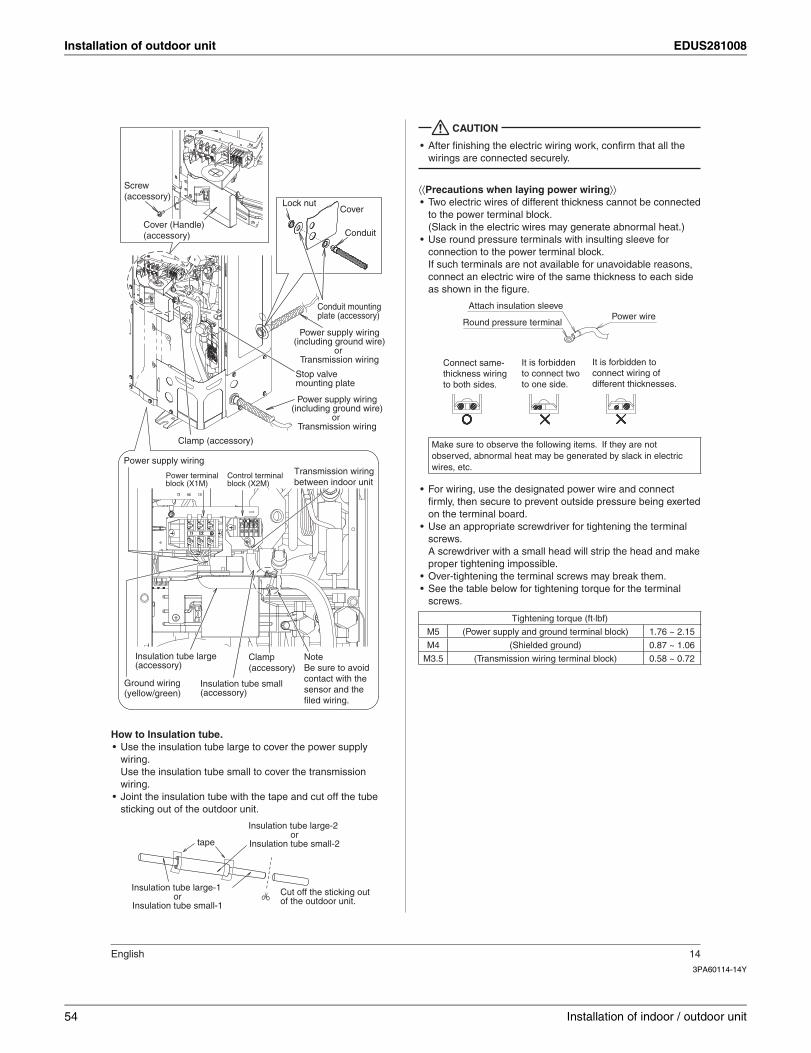
Installation of outdoor unit EDUS281008
3PA60114-14Y
English 14
Stop valve mounting plate
Conduit mounting plate (accessory)
Power supply wiring(including ground wire)
or Transmission wiring
Power supply wiring(including ground wire)
or Transmission wiring
Transmission wiring between indoor unit
Ground wiring (yellow/green)
Power supply wiring
Clamp (accessory)
Insulation tube small (accessory)
Insulation tube large (accessory)
Control terminal block (X2M)
Power terminal block (X1M)
Lock nutCover
Conduit
Clamp (accessory)
Note Be sure to avoid contact with the sensor and the filed wiring.
Cover (Handle)(accessory)
Screw(accessory)
How to Insulation tube.Use the insulation tube large to cover the power supply •wiring.Use the insulation tube small to cover the transmission wiring.Joint the insulation tube with the tape and cut off the tube •sticking out of the outdoor unit.
tape
Insulation tube large-1 or
Insulation tube small-1
Insulation tube large-2 or
Insulation tube small-2
Cut off the sticking out of the outdoor unit.
CAUTION
After fi nishing the electric wiring work, confi rm that all the •wirings are connected securely.
⟨⟨Precautions when laying power wiring⟩⟩Two electric wires of different thickness cannot be connected •to the power terminal block.(Slack in the electric wires may generate abnormal heat.)Use round pressure terminals with insulting sleeve for •connection to the power terminal block.If such terminals are not available for unavoidable reasons, connect an electric wire of the same thickness to each side as shown in the fi gure.
Power wireRound pressure terminal
Attach insulation sleeve
Connect same-thickness wiring to both sides.
It is forbidden to connect two to one side.
It is forbidden to connect wiring of different thicknesses.
Make sure to observe the following items. If they are not observed, abnormal heat may be generated by slack in electric wires, etc.
For wiring, use the designated power wire and connect •fi rmly, then secure to prevent outside pressure being exerted on the terminal board.Use an appropriate screwdriver for tightening the terminal •screws. A screwdriver with a small head will strip the head and make proper tightening impossible.Over-tightening the terminal screws may break them.•See the table below for tightening torque for the terminal •screws.
Tightening torque (ft·lbf)
M5 (Power supply and ground terminal block) 1.76 ~ 2.15
M4 (Shielded ground) 0.87 ~ 1.06
M3.5 (Transmission wiring terminal block) 0.58 ~ 0.72
54 Installation of indoor / outdoor unit
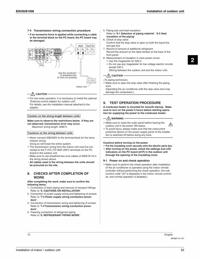
EDUS281008 Installation of outdoor unit
2
3PA60114-14Y
15 English
Transmission wiring connection procedure7-4If an excessive force is applied while connecting a cable •to the terminal block on the PC board, the PC board may be damaged.
IN/D OUT/D
F1F2 F1 F2
L1 L2
F1
IN/D OUT/DF2 F1 F2
F1 F2
Use the conductor of sheathed wire
(2 wire) (no polarity)
Indoor unit
CAUTION
For low-noise operation, it is necessary to install the optional •“External control adaptor for outdoor unit”.For details, see the installation manual attached to the adaptor.
Caution on the wiring length between units
Make sure to observe the restrictions below. If they are not observed, transmission error may occur.
Maximum wiring length: 3280 ft.
Cautions on the wiring between units
Never connect 208/230V to the terminal block for the trans-•mission wiring.Doing so will break the entire system.The transmission wiring from the indoor unit must be con-•nected to the F1/F2 (TO IN/D UNIT) terminals on the PC board in the outdoor unit.
∗ Make sure to use sheathed two-core cables of AWG18-16 in the wiring shown above.
∗ All cables used in the wiring between the units should be procured on the site.
CHECKS AFTER COMPLETION OF 8. WORK
After completing the work, make sure to confi rm the following items:
Connection of drain piping and removal of transport fi ttings:1. Refer to “5. CAUTIONS ON INSTALLATION”.Connection of power supply wiring and tightening of screws:2. Refer to “7-3 Power supply wiring connection proce-dure”.Connection of transmission wiring and tightening of screws:3. Refer to “7-4 Transmission wiring connection proce-dure”.Freezing connection of refrigerant piping4. Refer to “6. REFRIGERANT PIPING WORK”.
Piping size and heat insulation:5. Refer to “6-1 Selection of piping material”, “6-5 Heat insulation of the piping”.Check of stop valve:6. Confi rm that the stop valve is open on both the liquid line and gas line.Record of amount of additional refrigerant:7. Record the amount on the label sticked on the back of the front panel.Measurement of insulation in main power circuit:8.
Use the megatester for 500 V.•Do not use any megatester for low voltage electric circuits •except 230 V.(Wiring between the outdoor unit and the indoor unit)
CAUTION
<To piping technician>Make sure to open the stop valve after fi nishing the piping •work.(Operating the air conditioner with the stop valve shut may damage the compressor.)
TEST OPERATION PROCEDURE9. A crankcase heater is mounted for smooth startup. Make sure to turn on the power 6 hours before starting opera-tion for supplying the power to the crankcase heater.
WARNING
Make sure to close the outer panel before leaving the •outdoor unit in the power ON status.To avoid injury, always make sure that the overcurrent •protective device on the power supply panel of the installa-tion is switched off before doing any work.
Cautions before turning on the powerPut the insulating cover securely onto the electric parts box.•After turning on the power, check the settings and LED •indicators on the PC board (A1P) in the outdoor unit through the opening of the insulating cover.
Power on and check operation9-1Make sure to perform the check operation after installation. •(If the air conditioner is operated using the indoor remote controller without performing the check operation, the mal-function code “U3” is displayed in the indoor remote control-ler, and normal operation is disabled.)
Installation of indoor / outdoor unit 55
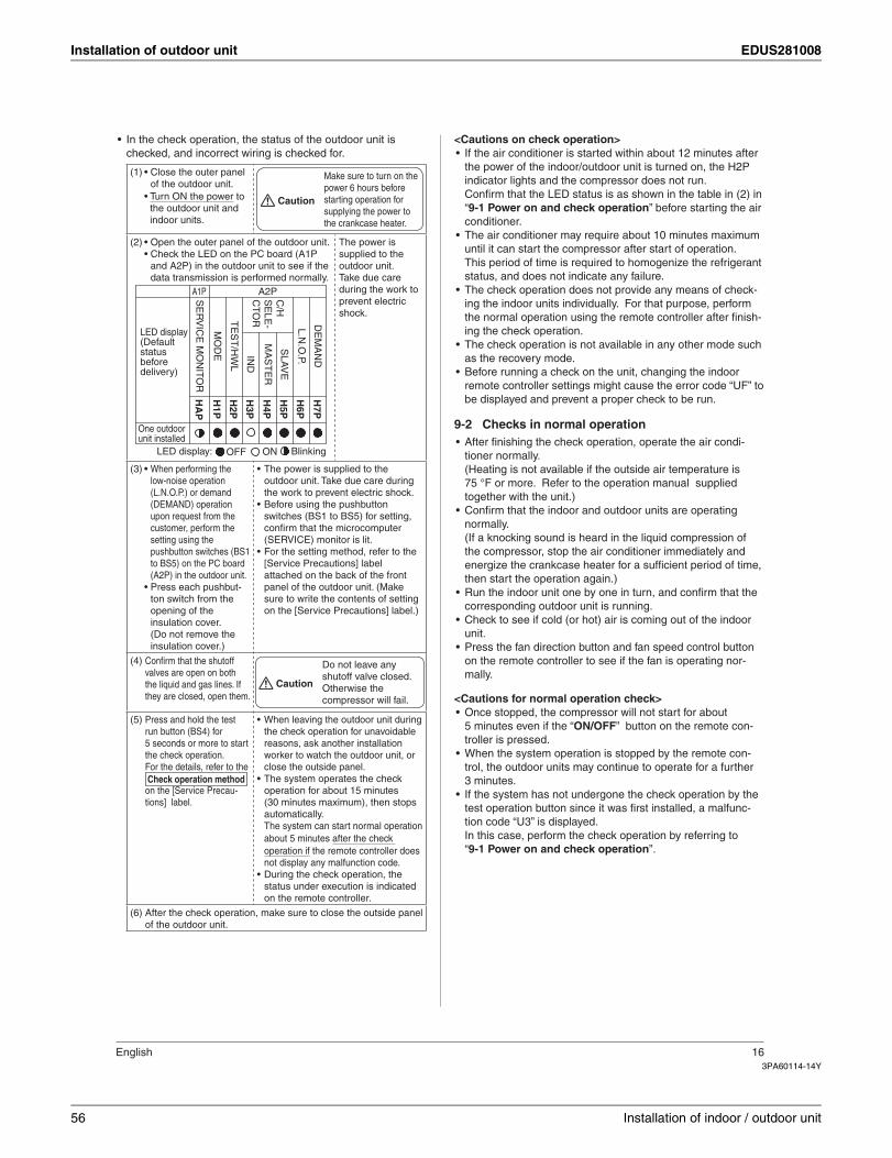
Installation of outdoor unit EDUS281008
3PA60114-14Y
English 16
In the check operation, the status of the outdoor unit is •checked, and incorrect wiring is checked for.
(1) • Close the outer panel of the outdoor unit.
• Turn ON the power to the outdoor unit and indoor units.
Caution
Make sure to turn on the power 6 hours before starting operation for supplying the power to the crankcase heater.
(2) • Open the outer panel of the outdoor unit.• Check the LED on the PC board (A1P
and A2P) in the outdoor unit to see if the data transmission is performed normally.
One outdoor unit installed
H1P
H5P
H4P
H6P
H7P
H2P
H3P
HA
P
BlinkingONOFFLED display:
LED display (Default status before delivery)
A1P A2PSE
RV
ICE
MO
NITO
R
MO
DE IN
D
SLA
VE
MA
ST
ER
TE
ST
/HW
L
C/H
S
ELE
-C
TOR
L.N.O
.P.
DE
MA
ND
The power is supplied to the outdoor unit.Take due care during the work to prevent electric shock.
(3) • When performing the low-noise operation (L.N.O.P.) or demand (DEMAND) operation upon request from the customer, perform the setting using the pushbutton switches (BS1 to BS5) on the PC board (A2P) in the outdoor unit.
• Press each pushbut-ton switch from the opening of the insulation cover. (Do not remove the insulation cover.)
The power is supplied to the •outdoor unit. Take due care during the work to prevent electric shock.Before using the pushbutton •switches (BS1 to BS5) for setting, confi rm that the microcomputer (SERVICE) monitor is lit.For the setting method, refer to the •[Service Precautions] label attached on the back of the front panel of the outdoor unit. (Make sure to write the contents of setting on the [Service Precautions] label.)
(4) Confi rm that the shutoff valves are open on both the liquid and gas lines. If they are closed, open them.
Caution
Do not leave any shutoff valve closed.Otherwise the compressor will fail.
(5) Press and hold the test run button (BS4) for 5 seconds or more to start the check operation.For the details, refer to the Check operation methodon the [Service Precau-tions] label.
When leaving the outdoor unit during •the check operation for unavoidable reasons, ask another installation worker to watch the outdoor unit, or close the outside panel.The system operates the check •operation for about 15 minutes (30 minutes maximum), then stops automatically.The system can start normal operation about 5 minutes after the check operation if the remote controller does not display any malfunction code.During the check operation, the •status under execution is indicated on the remote controller.
(6) After the check operation, make sure to close the outside panel of the outdoor unit.
<Cautions on check operation>If the air conditioner is started within about 12 minutes after •the power of the indoor/outdoor unit is turned on, the H2P indicator lights and the compressor does not run.Confi rm that the LED status is as shown in the table in (2) in “9-1 Power on and check operation” before starting the air conditioner.The air conditioner may require about 10 minutes maximum •until it can start the compressor after start of operation.This period of time is required to homogenize the refrigerant status, and does not indicate any failure.The check operation does not provide any means of check-•ing the indoor units individually. For that purpose, perform the normal operation using the remote controller after fi nish-ing the check operation.The check operation is not available in any other mode such •as the recovery mode.Before running a check on the unit, changing the indoor •remote controller settings might cause the error code “UF” to be displayed and prevent a proper check to be run.
Checks in normal operation9-2After fi nishing the check operation, operate the air condi-•tioner normally.(Heating is not available if the outside air temperature is 75 °F or more. Refer to the operation manual supplied together with the unit.)Confi rm that the indoor and outdoor units are operating •normally.(If a knocking sound is heard in the liquid compression of the compressor, stop the air conditioner immediately and energize the crankcase heater for a suffi cient period of time, then start the operation again.)Run the indoor unit one by one in turn, and confi rm that the •corresponding outdoor unit is running.Check to see if cold (or hot) air is coming out of the indoor •unit.Press the fan direction button and fan speed control button •on the remote controller to see if the fan is operating nor-mally.
<Cautions for normal operation check>Once stopped, the compressor will not start for about •5 minutes even if the “ON/OFF” button on the remote con-troller is pressed.When the system operation is stopped by the remote con-•trol, the outdoor units may continue to operate for a further 3 minutes.If the system has not undergone the check operation by the •test operation button since it was fi rst installed, a malfunc-tion code “U3” is displayed.In this case, perform the check operation by referring to “9-1 Power on and check operation”.
56 Installation of indoor / outdoor unit
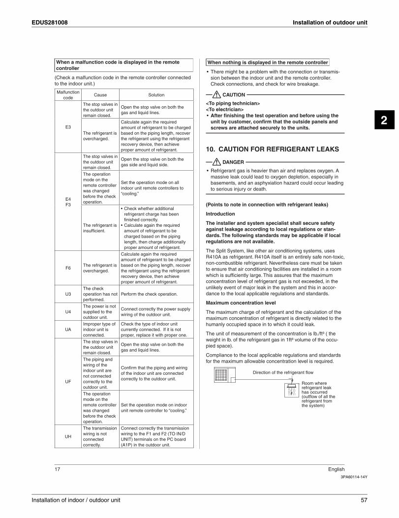
EDUS281008 Installation of outdoor unit
2
3PA60114-14Y
17 English
When a malfunction code is displayed in the remote controller
(Check a malfunction code in the remote controller connected to the indoor unit.)
Malfunctioncode
Cause Solution
E3
The stop valves in the outdoor unit remain closed.
Open the stop valve on both the gas and liquid lines.
The refrigerant is overcharged.
Calculate again the required amount of refrigerant to be charged based on the piping length, recover the refrigerant using the refrigerant recovery device, then achieve proper amount of refrigerant.
E4F3
The stop valves in the outdoor unit remain closed.
Open the stop valve on both the gas side and liquid side.
The operation mode on the remote controller was changed before the check operation.
Set the operation mode on all indoor unit remote controllers to “cooling.”
The refrigerant is insuffi cient.
Check whether additional •refrigerant charge has been fi nished correctly.Calculate again the required •amount of refrigerant to be charged based on the piping length, then charge additionally proper amount of refrigerant.
F6The refrigerant is overcharged.
Calculate again the required amount of refrigerant to be charged based on the piping length, recover the refrigerant using the refrigerant recovery device, then achieve proper amount of refrigerant.
U3The check operation has not performed.
Perform the check operation.
U4The power is not supplied to the outdoor unit.
Connect correctly the power supply wiring of the outdoor unit.
UAImproper type of indoor unit is connected.
Check the type of indoor unit currently connected. If it is not proper, replace it with proper one.
UF
The stop valves in the outdoor unit remain closed.
Open the stop valve on both the gas and liquid lines.
The piping and wiring of the indoor unit are not connected correctly to the outdoor unit.
Confi rm that the piping and wiring of the indoor unit are connected correctly to the outdoor unit.
The operation mode on the remote controller was changed before the check operation.
Set the operation mode on indoor unit remote controller to “cooling.”
UH
The transmission wiring is not connectedcorrectly.
Connect correctly the transmission wiring to the F1 and F2 (TO IN/D UNIT) terminals on the PC board (A1P) in the outdoor unit.
When nothing is displayed in the remote controller
There might be a problem with the connection or transmis-•sion between the indoor unit and the remote controller.Check connections, and check for wire breakage.
CAUTION
<To piping technician><To electrician>
After fi nishing the test operation and before using the •unit by customer, confi rm that the outside panels and screws are attached securely to the units.
CAUTION FOR REFRIGERANT LEAKS10.
DANGER
Refrigerant gas is heavier than air and replaces oxygen. A •massive leak could lead to oxygen depletion, especially in basements, and an asphyxiation hazard could occur leading to serious injury or death.
(Points to note in connection with refrigerant leaks)
Introduction
The installer and system specialist shall secure safety against leakage according to local regulations or stan-dards. The following standards may be applicable if local regulations are not available.
The Split System, like other air conditioning systems, uses R410A as refrigerant. R410A itself is an entirely safe non-toxic, non-combustible refrigerant. Nevertheless care must be taken to ensure that air conditioning facilities are installed in a room which is suffi ciently large. This assures that the maximum concentration level of refrigerant gas is not exceeded, in the unlikely event of major leak in the system and this in accor-dance to the local applicable regulations and standards.
Maximum concentration level
The maximum charge of refrigerant and the calculation of the maximum concentration of refrigerant is directly related to the humanly occupied space in to which it could leak.
The unit of measurement of the concentration is lb./ft³ ( the weight in lb. of the refrigerant gas in 1ft³ volume of the occu-pied space).
Compliance to the local applicable regulations and standards for the maximum allowable concentration level is required.
Direction of the refrigerant flow
Room where refrigerant leak has occurred (outflow of all the refrigerant from the system)
Installation of indoor / outdoor unit 57
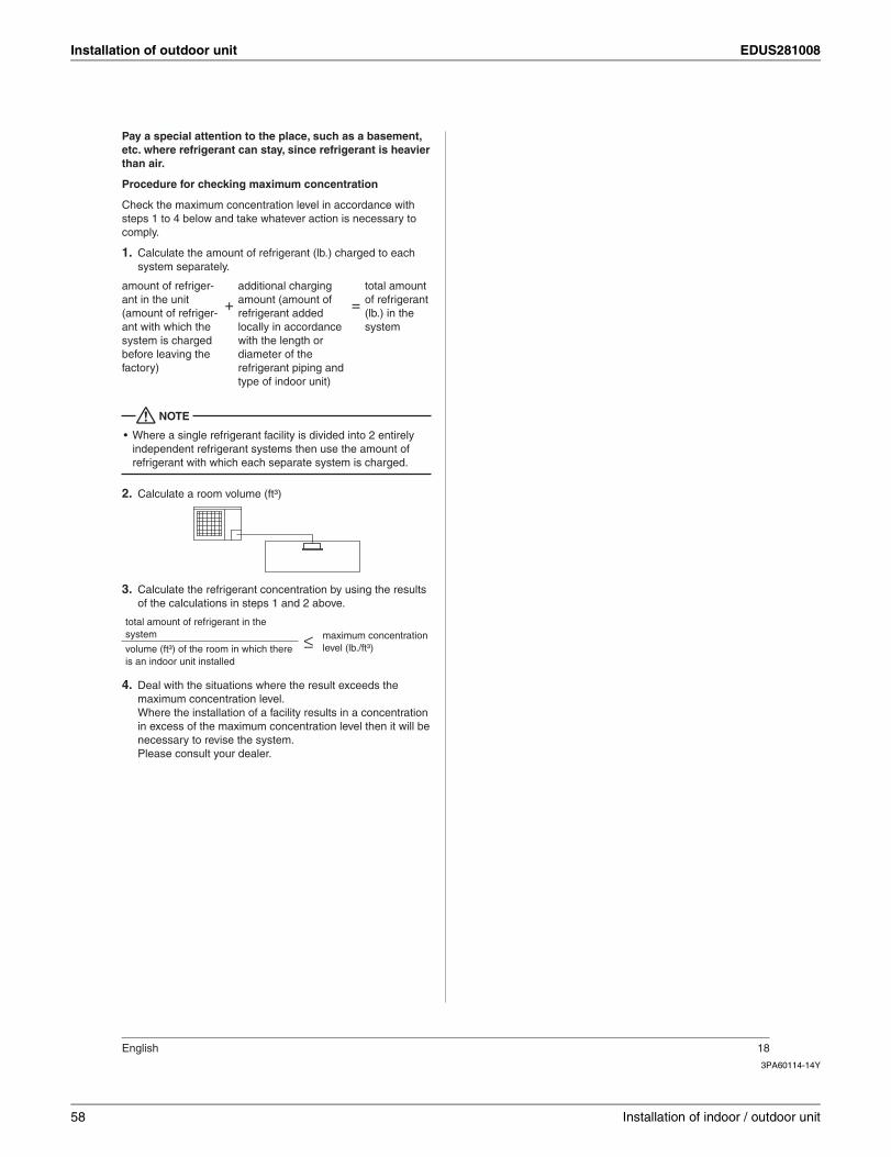
Installation of outdoor unit EDUS281008
3PA60114-14Y
English 18
Pay a special attention to the place, such as a basement, etc. where refrigerant can stay, since refrigerant is heavier than air.
Procedure for checking maximum concentration
Check the maximum concentration level in accordance with steps 1 to 4 below and take whatever action is necessary to comply.
Calculate the amount of refrigerant (lb.) charged to each 1. system separately.
amount of refriger-ant in the unit (amount of refriger-ant with which the system is charged before leaving the factory)
+additional charging amount (amount of refrigerant added locally in accordance with the length or diameter of the refrigerant piping and type of indoor unit)
=total amount of refrigerant (lb.) in the system
NOTE
Where a single refrigerant facility is divided into 2 entirely •independent refrigerant systems then use the amount of refrigerant with which each separate system is charged.
Calculate a room volume (ft³)2.
Calculate the refrigerant concentration by using the results 3. of the calculations in steps 1 and 2 above.
total amount of refrigerant in the system ≤ maximum concentration
level (lb./ft³)volume (ft³) of the room in which there is an indoor unit installed
Deal with the situations where the result exceeds the 4. maximum concentration level.Where the installation of a facility results in a concentration in excess of the maximum concentration level then it will be necessary to revise the system.Please consult your dealer.
58 Installation of indoor / outdoor unit
EDUS281008
Detail information of options 59
3
Part 3
Detail informationof options
1. Accessories...............................................................................................601.1 Indoor unit .................................................................................................. 601.2 Outdoor unit................................................................................................ 60
2. RZQ...........................................................................................................612.1 KKPJ5F180 — Central drain plug .............................................................. 612.2 K-KYZP15C — Wire fixture for preventing overturning .............................. 632.3 KPT-60B160 — Fixture for preventing overturning .................................... 65
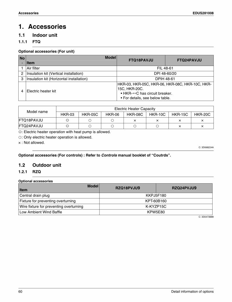
Accessories EDUS281008
1. Accessories1.1 Indoor unit1.1.1 FTQ
Optional accessories (For unit)
.: Electric heater operation with heat pump is allowed.k: Only electric heater operation is allowed.× : Not allowed.
C: 3D068224A
Optional accessories (For controls) : Refer to Controls manual booklet of “Coutrds”.
1.2 Outdoor unit1.2.1 RZQ
Optional accessories
C: 3D047388B
No.
ModelFTQ18PAVJU FTQ24PAVJU
Item1 Air filter FIL 48-612 Insulation kit (Vertical installation) DPI 48-60/203 Insulation kit (Horizontal installation) DPIH 48-61
4 Electric heater kit
HKR-03, HKR-05C, HKR-06, HKR-08C, HKR-10C, HKR-15C, HKR-20C.
• HKR-∗∗C has circuit breaker.• For details, see below table.
Model nameElectric Heater Capacity
HKR-03 HKR-05C HKR-06 HKR-08C HKR-10C HKR-15C HKR-20C
FTQ18PAVJU . k k × × × ×
FTQ24PAVJU . k k k k × ×
ModelItem RZQ18PVJU9 RZQ24PVJU9
Central drain plug KKPJ5F180
Fixture for preventing overturning KPT-60B160
Wire fixture for preventing overturning K-KYZP15C
Low Ambient Wind Baffle KPW5E80
60 Detail information of options
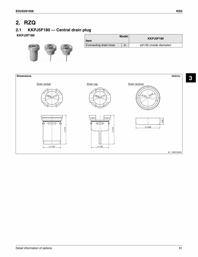
EDUS281008 RZQ
3
2. RZQ2.1 KKPJ5F180 — Central drain plugKKPJ5F180 Model
KKPJ5F180Item
Connecting drain hose in. φ31/32 (inside diameter)
Dimensions Unit:in.
JC : D3K1342A
Drain socket Drain cap Drain receiver
25/32 1-1/4 25/32 1-1/4 1-3/16 31/32
13/3
2
1-11
/16 1-13/32
1-1/32
1-11
/16
1-1/32
Detail information of options 61
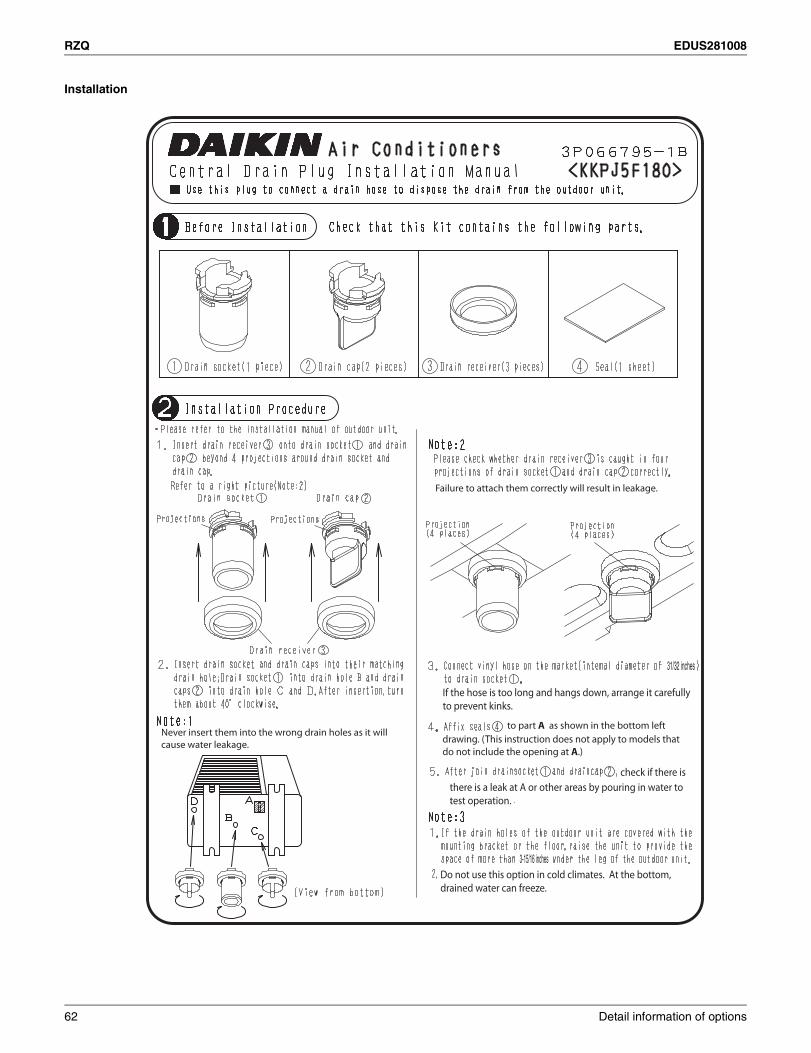
RZQ EDUS281008
Installation
31/32 inches
3-15/16 inches
Never insert them into the wrong drain holes as it willcause water leakage.
Failure to attach them correctly will result in leakage.
If the hose is too long and hangs down, arrange it carefullyto prevent kinks.
to part A as shown in the bottom left
drawing. (This instruction does not apply to models that do not include the opening at A.)
check if there isthere is a leak at A or other areas by pouring in water to test operation.
Do not use this option in cold climates. At the bottom,drained water can freeze.
62 Detail information of options
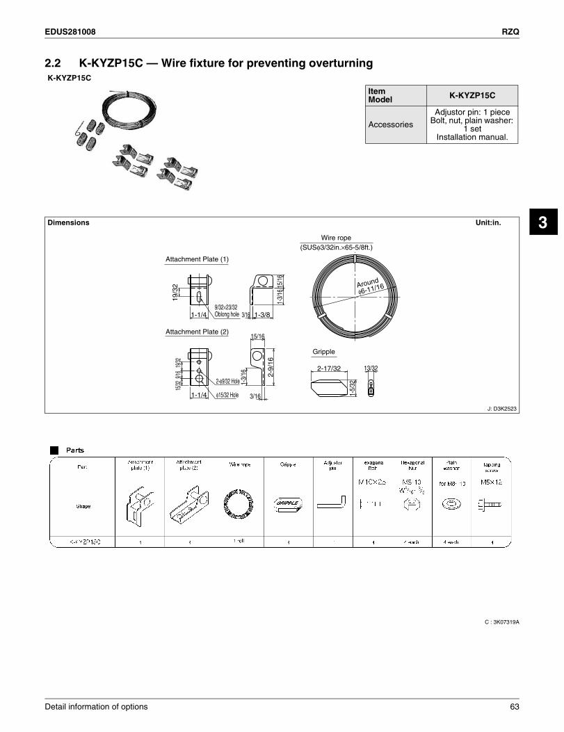
EDUS281008 RZQ
3
2.2 K-KYZP15C — Wire fixture for preventing overturning
C : 3K07319A
K-KYZP15C
Dimensions Unit:in.
J: D3K2523
ItemModel K-KYZP15C
Accessories
Adjustor pin: 1 pieceBolt, nut, plain washer:
1 setInstallation manual.
2-17/32
1-5/
32
Around
φ6-11/16
13/32
1-1/4 1-3/8
19/3
2 15/1
6
9/32×23/32 Oblong hole
1-1/4 φ15/32 Hole
2-9/
16
15/32
9/16
19/32
15/16
2-φ9/32 Hole
1-3/
16
1-3/
16
3/16
3/16
(SUSφ3/32in.×65-5/8ft.)
Attachment Plate (1)
Attachment Plate (2)
Gripple
Wire rope
Detail information of options 63
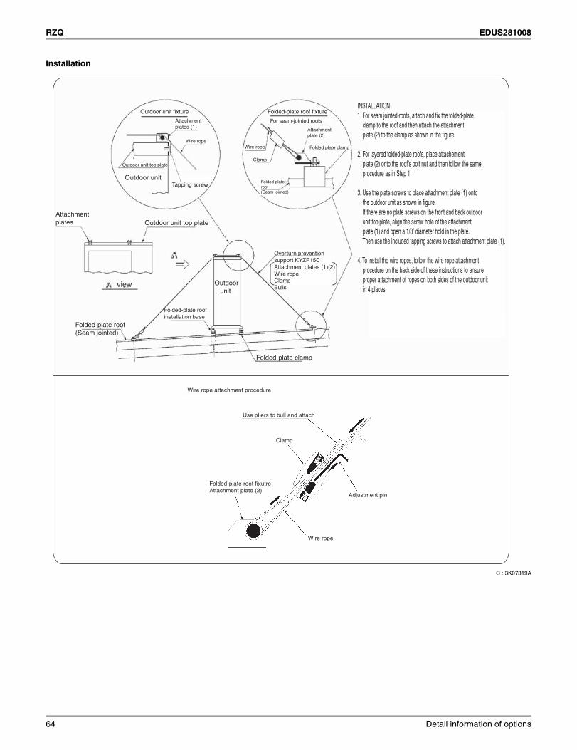
RZQ EDUS281008
Installation
C : 3K07319A
Use pliers to bull and attach
INSTALLATION1. For seam jointed-roofs, attach and fix the folded-plate clamp to the roof and then attach the attachment plate (2) to the clamp as shown in the figure.
2. For layered folded-plate roofs, place attachement plate (2) onto the roof’s bolt nut and then follow the same procedure as in Step 1.
3. Use the plate screws to place attachment plate (1) onto the outdoor unit as shown in figure. If there are no plate screws on the front and back outdoor unit top plate, align the screw hole of the attachment plate (1) and open a 1/8” diameter hold in the plate. Then use the included tapping screws to attach attachment plate (1).
4. To install the wire ropes, follow the wire rope attachment procedure on the back side of these instructions to ensure proper attachment of ropes on both sides of the outdoor unit in 4 places.
Folded-plate roof(Seam jointed)
Outdoor unit top plate
Attachment plates
Overturn preventionsupport KYZP15CAttachment plates (1)(2)Wire ropeClampBulls
Outdoor unit
Folded-plate clamp
Folded-plate roofinstallation base
Outdoor unit fixture Folded-plate roof fixture
Outdoor unit Tapping screw
Attachment plates (1)
Outdoor unit top plate
Wire ropeWire rope
Folded-plateroof(Seam jointed)
Clamp
For seam-jointed roofs
Attachmentplate (2)
Folded plate clamp
view
Wire rope attachment procedure
Folded-plate roof fixutreAttachment plate (2)
Clamp
Adjustment pin
Wire rope
64 Detail information of options
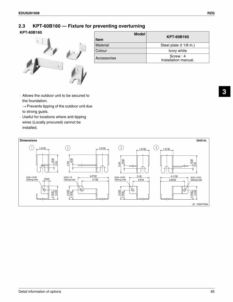
EDUS281008 RZQ
3
2.3 KPT-60B160 — Fixture for preventing overturningKPT-60B160 Model
KPT-60B160ItemMaterial Steel plate (t 1/8 in.)
Colour Ivory white
Accessories Screw : 4Installation manual.
· Allows the outdoor unit to be secured to the foundation.→ Prevents tipping of the outdoor unit due to strong gusts.
· Useful for locations where anti-tipping wires (Locally procured) cannot be installed.
Dimensions Unit:in.
JC : D3K2759A
1-31/32
23/324-27/32
4-7/323-1/8
2-9/164-11/32
3-25/32
1-31/32 1-31/32 1-31/32
15/3
21-
15/3
2
1-15
/32
2-3/
32
2-3/
32
1-15
/32
1-15
/32
2-3/
32
2-3/
32
15/3
2
2-3/
4
2-3/
4
15/3
2
15/3
2
2-3/
4
2-3/
4
9/32×13/32Oblong hole
9/32×13/32Oblong hole
9/32×13/32Oblong hole
9/32×1/2Oblong hole
Detail information of options 65
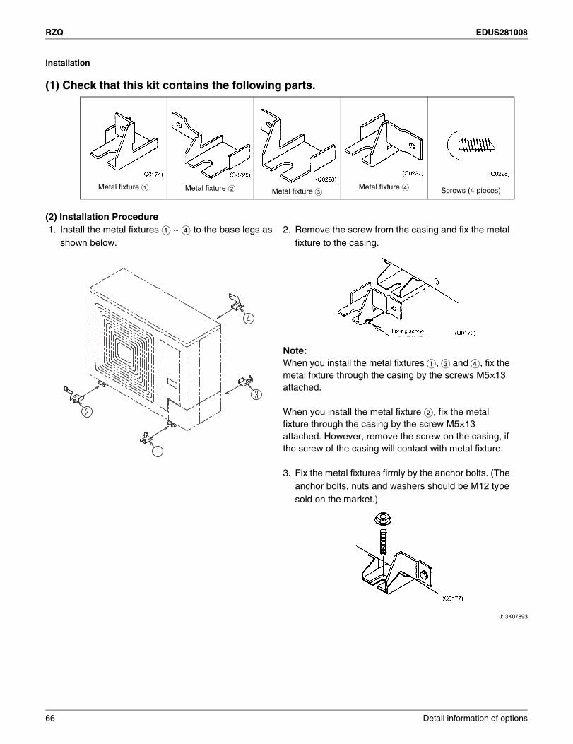
RZQ EDUS281008
Installation
(1) Check that this kit contains the following parts.
(2) Installation Procedure
J: 3K07893
Metal fixture N Metal fixture O Metal fixture PMetal fixture Q Screws (4 pieces)
1. Install the metal fixtures N=~ Q to the base legs as shown below.
2. Remove the screw from the casing and fix the metal fixture to the casing.
Note:When you install the metal fixtures N, P=and Q, fix the metal fixture through the casing by the screws M5×13 attached.
When you install the metal fixture O, fix the metal fixture through the casing by the screw M5×13 attached. However, remove the screw on the casing, if the screw of the casing will contact with metal fixture.
3. Fix the metal fixtures firmly by the anchor bolts. (The anchor bolts, nuts and washers should be M12 type sold on the market.)
66 Detail information of options

1645 Wallace Drive, Suite 110Carrollton, TX75006
AMERICAS
dddddfdf
ISO 9001 is a plant certification systemdefined by the International Organizationfor Standardization (ISO) relating to quality assurance. ISO 9001 certificationcovers quality assurance aspects relatedto the “design, development, manufacture, installation, and supplementary service” of products manufactured at the plant.
ISO 14001 is the standard defined by theInternational Organization for Standardization(ISO) relating to environmental managementsystems. Our group has been acknowledged byan internationally accredited program of environmental protection procedures and activities to meet the requirements of ISO 14001.
Specifications, designs and other content appearing in this brochure are current as of December 2010 but subject to change without notice.
EDUS281008Printed in U.S.A. 12/2010 B AK
Daikin Industries, Ltd.’s products are manufactured for export to numerous countries throughout theworld. Daikin Industries, Ltd. does not have control over which products are exported to and used in aparticular country. Prior to purchase, please therefore confirm with your local authorized importer,distributor and/or retailer whether this product conforms tot he applicable standards, and is suitable foruse, in the region where the product will be used. This statement does not purport to exclude, restrict ormodify the application of any local legislation.
Ask a qualified installer or contractor to install this product. Do not try to install the product yourself.Improper installation can result in water or refrigerant leakage, electrical shock, fire, or explosion.
Use only those parts and accessories supplied or specified by Daikin. Ask a qualified installer orcontractor to install those parts and accessories. Use of unauthorized parts and accessories or improper installation of parts and accessories can result in water or refrigerant leakage, electrical shock, fire, or explosion.
Read the User’s Manual carefully before using this product. The User’s Manual provides importantsafety instructions and warnings. Be sure to follow these instructions and warnings.
If you have any inquiries, please contact your local importer, distributor, or retailer.
©2010 Daikin Industries, Limited.
Daikin® AC Absolute Comfort®, and its design, VRV®, REFNET™, and Quaternity™ are registered trademarks of Daikin Industries, Limited. All rights reserved. LonWorks® and LON® are registered trademarks of Echelon Corporation. BACnet® is a Data Communication Protocal for Building Automation and Control Networks, developed under the auspices of the American Society of Heating, Refrigeratin, and Air-Conditioning Engineers (ASHRAE).