Embed Size (px)
Citation preview
Course No. ME402 Group No. A24
Experiment No. 05Name of the Experiment: STUDY OF BUET POWER PLANT.
Date of submission: Name: Raihan Tayeb 31.05.2011 Student No: 0610070Date of performance: Dept: ME Sec: A 23.05.2011 Level: 4 Term:1

Objective:
The objective of this experiment is to study the different systems of the generators of the BUET power plant.
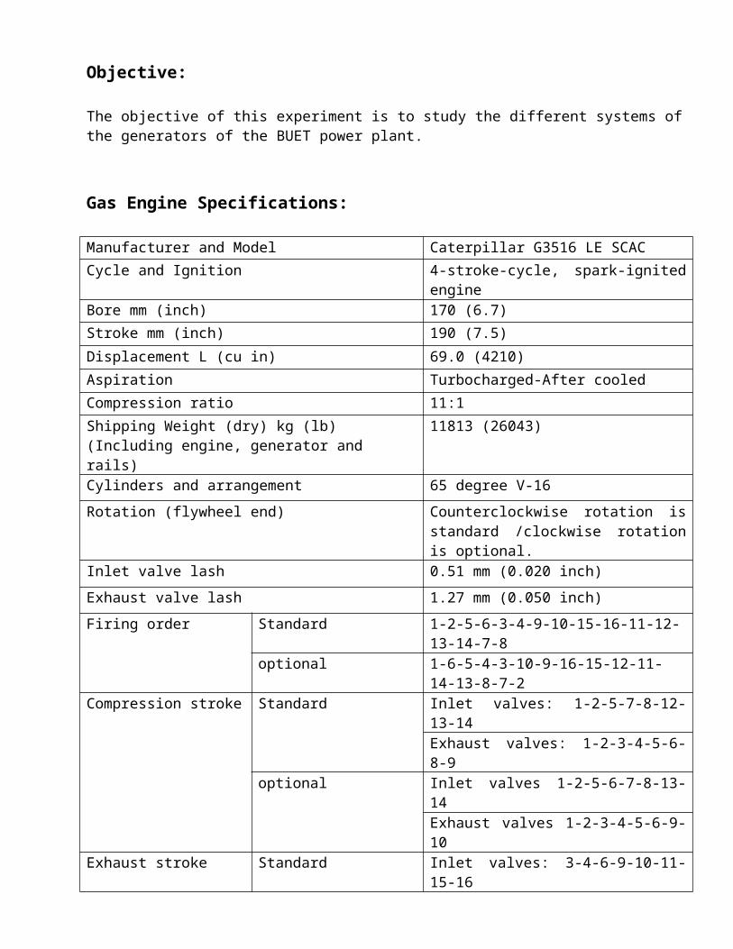
Gas Engine Specifications:
Manufacturer and Model Caterpillar G3516 LE SCAC
Cycle and Ignition 4-stroke-cycle, spark-ignited engine
Bore mm (inch) 170 (6.7)
Stroke mm (inch) 190 (7.5)
Displacement L (cu in) 69.0 (4210)
Aspiration Turbocharged-After cooled
Compression ratio 11:1
Shipping Weight (dry) kg (lb) (Including engine, generator and rails)
11813 (26043)
Cylinders and arrangement 65 degree V-16
Rotation (flywheel end) Counterclockwise rotation is standard /clockwise rotation is optional.
Inlet valve lash 0.51 mm (0.020 inch)
Exhaust valve lash 1.27 mm (0.050 inch)
Firing order Standard 1-2-5-6-3-4-9-10-15-16-11-12-13-14-7-8
optional 1-6-5-4-3-10-9-16-15-12-11-14-13-8-7-2
Compression stroke Standard Inlet valves: 1-2-5-7-8-12-13-14Exhaust valves: 1-2-3-4-5-6-8-9
optional Inlet valves 1-2-5-6-7-8-13-14Exhaust valves 1-2-3-4-5-6-9-10
Exhaust stroke Standard Inlet valves: 3-4-6-9-10-11-15-16Exhaust valves: 7-10-11-12-13-14-15-16
optional Inlet valves 3-4-9-10-11-12-15-16Exhaust valves 7-8-11-12-13-14-15-16
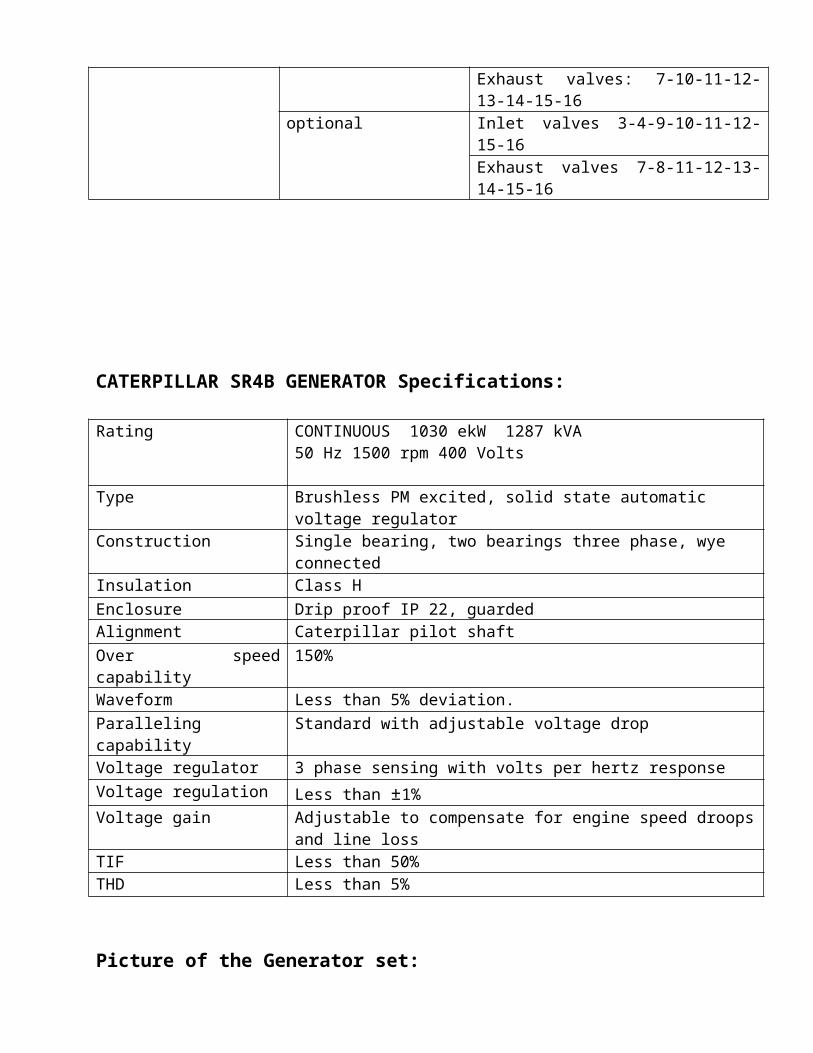
CATERPILLAR SR4B GENERATOR Specifications:
Rating CONTINUOUS 1030 ekW 1287 kVA 50 Hz 1500 rpm 400 Volts
Type Brushless PM excited, solid state automatic voltage regulator
Construction Single bearing, two bearings three phase, wye connected
Insulation Class H
Enclosure Drip proof IP 22, guardedAlignment Caterpillar pilot shaft
Over speed capability 150%
Waveform Less than 5% deviation.
Paralleling capability Standard with adjustable voltage dropVoltage regulator 3 phase sensing with volts per hertz response
Voltage regulation Less than ±1%Voltage gain Adjustable to compensate for engine speed droops and line loss
TIF Less than 50%THD Less than 5%
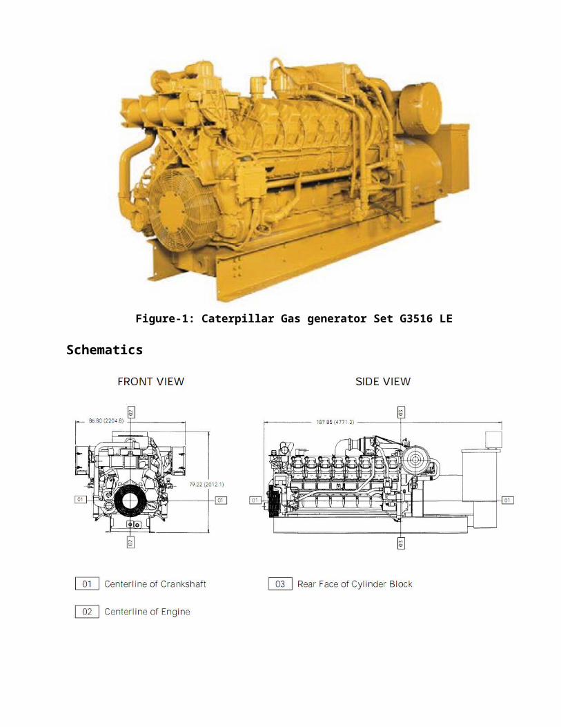
Picture of the Generator set:
Figure-1: Caterpillar Gas generator Set G3516 LE
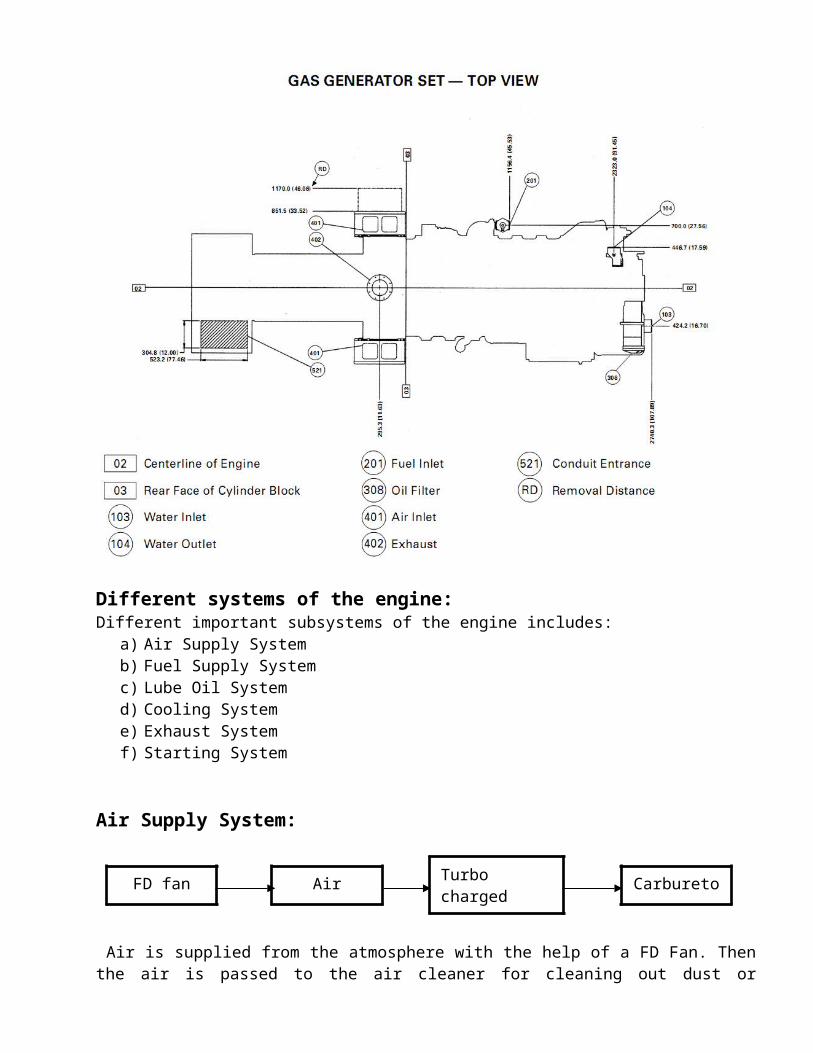
Schematics
Different systems of the engine:
Different important subsystems of the engine includes:a) Air Supply Systemb) Fuel Supply Systemc) Lube Oil Systemd) Cooling Systeme) Exhaust Systemf) Starting System
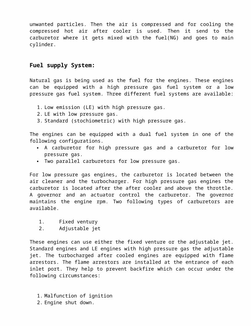
Air Supply System:
Air is supplied from the atmosphere with the help of a FD Fan. Then the air is passed to the air cleaner for cleaning out dust or unwanted particles. Then the air is compressed and for cooling the compressed hot air after cooler is used. Then it send to the carburetor where it gets mixed with the fuel(NG) and goes to main cylinder.
Fuel supply System:
Natural gas is being used as the fuel for the engines. These engines can be equipped with a high pressure gas fuel system or a low pressure gas fuel system. Three different fuel systems are available:
1. Low emission (LE) with high pressure gas.2. LE with low pressure gas.3. Standard (stochiometric) with high pressure gas.
The engines can be equipped with a dual fuel system in one of the following configurations. A carburetor for high pressure gas and a carburetor for low pressure gas. Two parallel carburetors for low pressure gas.
For low pressure gas engines, the carburetor is located between the air cleaner and the turbocharger. For high pressure gas engines the carburetor is located after the after cooler and above the throttle. A governor and an actuator control the carburetor. The governor maintains the engine rpm. Two following types of carburetors are available.
1. Fixed ventury2. Adjustable jet
These engines can use either the fixed venture or the adjustable jet. Standard engines and LE engines with high pressure gas the adjustable jet. The turbocharged after cooled engines are equipped with flame arrestors. The flame arrestors are installed at the entrance of each inlet port. They help to prevent backfire which can occur under the following circumstances:
1. Malfunction of ignition
FD fan Air CleanerTurbo charged after cooler
Carburetor
2. Engine shut down.
The flame arrestors will extinguish the flame before the flame can ignite in the inlet manifold.
Lubrication System:
A gear driven pump supplies the engine lube oil. The oil is cooled and filtered. A by pass valve provides unrestricted flow of lubrication oil to the engine parts if the oil filter elements become plugged. The by pass valve will open if the filter differential pressure reaches 40 Psi.
Cooling System:
The standard cooling system has a gear driven centrifugal pump. Four temperature regulators regulate the temperature of the coolant.
Flow Chart: Single System
The turbocharged engine has Separate Circuit after Cooled (SCAC). The after cooler is required to operate at one of the following three temperatures. The temperature depends on the engine rating and the application.
Oil Pan Gear Pump Oil filter
Oil Drain Engine parts
Water Tank
Engine Parts
Gear Driven Centrifugal pump
Water Jacket
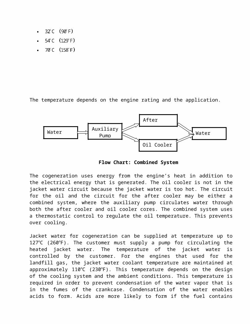
The temperature depends on the engine rating and the application.
Flow Chart: Combined System
The cogeneration uses energy from the engine’s heat in addition to the electrical energy that is generated. The oil cooler is not in the jacket water circuit because the jacket water is too hot. The circuit for the oil and the circuit for the after cooler may be either a combined system, where the auxiliary pump circulates water through both the after cooler and oil cooler cores. The combined system uses a thermostatic control to regulate the oil temperature. This prevents over cooling.
Jacket water for cogeneration can be supplied at temperature up to 127oC (260oF). The customer must supply a pump for circulating the heated jacket water. The temperature of the jacket water is controlled by the customer. For the engines that used for the landfill gas, the jacket water coolant temperature are maintained at approximately 110oC (230oF). This temperature depends on the design of the cooling system and the ambient conditions. This temperature is required in order to prevent condensation of the water vapor that is in the fumes of the crankcase. Condensation of the water enables acids to form. Acids are more likely to form if the fuel contains contaminants such as chlorides, fluorides and halides. Acids will cause severe internal damage to the engine.
For engines that used landfill gas, the coolant that is supplied to the after cooler is maintained at a temperature of 54oC (129oF). This prevents condensation of moisture in the inlet air piping.
Exhaust System:
There are two exhaust valves on the cylinder head in the engine. These allow escaping the exhaust gas easily. There is a gas turbine (Turbocharger) attached in the exhaust line. The function of this turbine is to compress the inlet air after entering the engine cylinders.
Normally the temperature of the exhaust gas is C when it goes through the individual pipe line. When it goes to a common line then the temperature of the exhaust gas is reduced to C .
Water Tank Auxiliary Pump
After Cooler
Oil Cooler
Water Tank
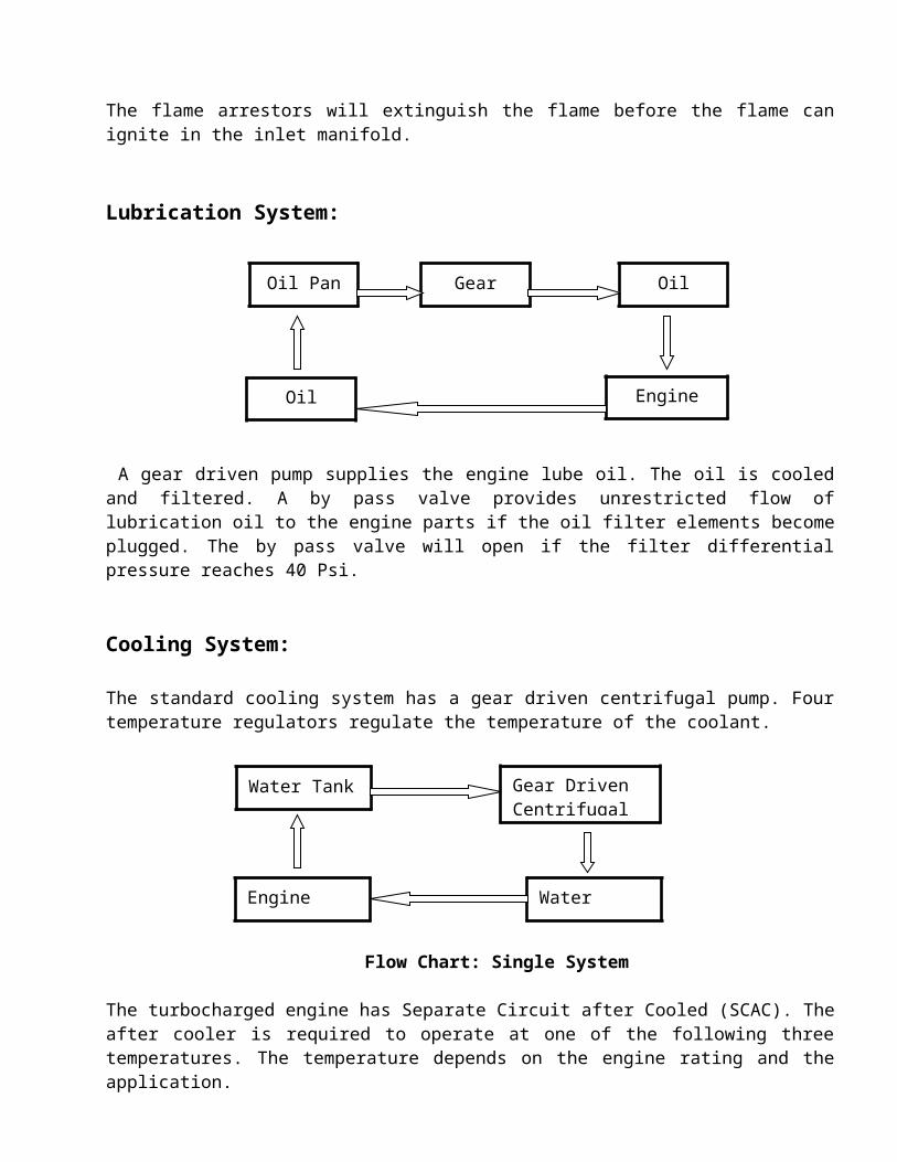
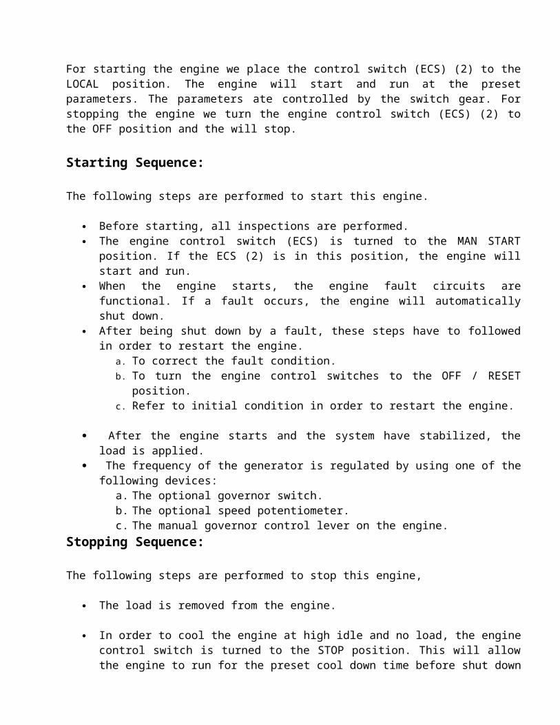
Fig: Valve Arrangements
Starting system:
The engine starts by battery, here two motor is used and 24 DC supply is needed.
For starting the engine we place the control switch (ECS) (2) to the LOCAL position. The engine will start and run at the preset parameters. The parameters ate controlled by the switch gear. For stopping the engine we turn the engine control switch (ECS) (2) to the OFF position and the will stop.
Starting Sequence:
The following steps are performed to start this engine.
Before starting, all inspections are performed. The engine control switch (ECS) is turned to the MAN START position. If the ECS (2)
is in this position, the engine will start and run. When the engine starts, the engine fault circuits are functional. If a fault occurs, the
engine will automatically shut down. After being shut down by a fault, these steps have to followed in order to restart the
engine.a. To correct the fault condition.b. To turn the engine control switches to the OFF / RESET position.c. Refer to initial condition in order to restart the engine.
After the engine starts and the system have stabilized, the load is applied. The frequency of the generator is regulated by using one of the following devices:
a. The optional governor switch.b. The optional speed potentiometer.c. The manual governor control lever on the engine.
Stopping Sequence:
The following steps are performed to stop this engine,
The load is removed from the engine.
In order to cool the engine at high idle and no load, the engine control switch is turned to the STOP position. This will allow the engine to run for the preset cool down time before shut down
For cooling down the engine at no load the engine speed is reduced to low idle. On 60 Hz units, low idle is approximately 66% of the full load speed. If the governor has an electric motor, the governor switch is pushed down until low idle is achieved. On electronic governors, the speed potentiometer is turned down until low idle is achieved. For manual governors, the governor control lever is moved to the low idle position.
While the engine is at the low idle, the engine oil level is measured. Oil level must be maintained between the “ADD” and “FULL” marks on the “Engine Running” side of the dipstick. In order to allow the engine to cool down, the engine is run at low idle approximately five minutes. After the engine cools, the engine control switch is turned to the OFF/RESET position.
For Emergency Stopping:
For emergency case emergency stop push button is used to shut down the engine. It will be necessary to reset the push button. Before starting emergency stop buttons that are located on the engine junction box are checked. If the emergency stop button was used to stop the engine the air shutoff has to be reset.
Power Distribution System:
The generators are operated in isochronous mode i.e. the supply frequency is kept constant. When load increases, frequency drops. This drop is sensed by governor and it increases fuel supply. When the 3 generators are operated simultaneously, they must be synchronized. The developed power first comes to the bus bar in the central control. From here it is sent to the substations routing the power to LT lines. There are 9 substations for distributing power:
Main Substation 1 Main Substation 2 Main Substation 3 Dr. Rashid Hall substation N.l Hall substation-old N.l Hall substation-new Academic Building Substation (Not operational)
Data Sheet
Table-1: Data of power plant
Parameter Unit-1 Unit-2Operational time (Hour) 15 15Energy (MWH) 9.9 9.31Load (%) 51.53 48.47Total Gas consumption (Nm3) 3749Gas consumption (Nm3) 1931.8597 1817.1403Rate of Gas consumption (Nm3/hr) 128.79 121.14
Table: Performance of Unit-2
Assuming, Standard condition and no loss.So, Electric Power output (KW) = BKw
Time (hr)
Electric Power output (KW)
BKw Bsfc (Nm3/BKw-hr)
Exhaust gas temp
Cooling water inlet temp
Cooling water outlet temp
1 480 480 0.252375 467.5 70 742 620 620 0.195387 457 - 763 651 651 0.186083 456 - 804 695 695 0.174302 458 - 765 660 660 0.183545 481.5 - 766 636 636 0.190472 478 - 767 710 710 0.170619 472.5 68 788 744 744 0.162822 471.5 68 809 650 650 0.186369 483 72 8010 605 605 0.200231 485 68 7611 625 625 0.193824 485.5 68 7412 612 612 0.197941 484 66 7213 482 482 0.251327 489 66 7214 475 475 0.255032 501.5 - 7415 448 448 0.270402 499 66 7016 422 422 0.287061 503 66 70
Sample Calculation:
Gas meter reading at 01.04.08 = 3420109 Nm3
Gas meter reading at 02.04.08 = 3423858 Nm3
Operational Time from 01.04.08 to 02.04.08 = 15 Hours.
Gas Consumption at 15 hours = 3420109 – 3423858 = 3749 Nm3
Unit-1
Energy meter reading at 01.04.08 = 9054.50 MWH
Energy meter reading at 02.04.08 = 9064.40 MWH
Net energy = 9.9 MWH
Load Share = 9.9 / (9.9+9.31) = 51.53 %
Gas Consumption per hour = 128.79 Nm3/hr
Unit-2
Energy meter reading at 01.04.08 = 9419.88 MWH
Energy meter reading at 02.04.08 = 9429.19 MWH
Net energy = 9.31 MWH
Load share= 9.31 / (9.9+9.31) = 48.47 %
Gas Consumption per hour = 121.14 Nm3/hr
Observation no. 1
Time: 9.00 AM
Unit -2
Assuming, Standard condition and no loss.So, Electric Power output (KW) = BKwElectric Power output = 480 KWBKw = 480 KW
Bsfc = Gas Consumption per hour / BKw = 121.14 / 480 = 0.252375 Nm3/BKw-hr
Stack left temp = 480 ºCStack left temp = 455 ºC
Exhaust temp = (480 + 455) / 2 = 467.5 ºC
Discussion:
In general, from the BUET power plant power is supplied to the teacher’s residential area, student’s residential halls, academic building etc. The power is supplied from 8.00 am to 12 am. The rest of the time, power is supplied from DESA.
There are 3 gas engine generators in the power plant of BUET. Two of the generators produce 2060 KW. The other one produces 1950KW giving the total capacity of 4 MW.
Starting of the engines require cranking which is done by two starting motors. The motors get supply from four 12 volt dc batteries (200 amp.hr each), which are combined in series and parallel combination to get the exact voltage for starting.
There is a combined cooling tower in the power plant. Induced draft fans are being used in the cooling tower. But in the 2MW generator set forced draft fans are used.
Although we have the capacity to produce 4MW, at peak load in summer the maximum power requirement here at BUET is around 1.5 MW. As a result the engines are run in a part load of about 60%. Although running at part load is hampering the best possible or most economic energy production, it might result in a longer service life for the engines.
The other possible scenario for being most efficient could have been being connected to the national grid; supplying to the grid when having excess power and taking from the grid when running short. However, stringent transmission regulations and possible complicacy in power exchange transaction prevented that scenario to come to life and we are running as an isolated or standalone unit to date.
Nevertheless, the question of energy security is still at large. The gas reserve of our country is running low. Since all our power generation is dependent on gas supply, a sudden crisis of NG could have catastrophic impact. So there are future plans to acquire a new diesel generator to be prepared for that sort of situations.