Embed Size (px)
Citation preview

Specification For Microprocessor Controlled Air Brake System For WDG4 / WDP4 and Alco Locomotives
Specification No.MP-0.01.00.20, Rev.03, April-2016
Page 1 of 17
Specification For Microprocessor Controlled Air Brake System For WDG4 /
WDP4 and ALCo Locomotives
1. SCOPE
This specification covers the functional requirement of Microprocessor Controlled air brake
system for WDG4, WDP4 and ALCo diesel locomotives and this specification would assist
in purchase, inspection, testing and acceptance requirements. This Microprocessor Controlled
air brake system will be fitted on new WDG4, WDP4 and existing as well as new ALCo
diesel locomotives. This specification supersedes earlier specification no. MP-0.01.00.20,
Rev.01, June-2007 and MP.0.01.00.07, Rev 01 Aug 2007.
2. BASIC RELEVANT DATA OF LOCOMOTIVE
Basic data of WDG4, WDP4 and ALCO diesel locomotive relevant to brake system is as
under:
2.1 Capacity of compressor:
Compressor capacity (FAD) at 10 kg/cm2 pressure:
S.no. WDG4 & WDP4 diesel Locomotive ALCO diesel Locomotive
i) 200 rpm.
(Idle speed)
990 lpm
350 rpm.
(Idle speed)
2130 lpm
ii) 950 rpm
(Max. speed)
5677 lpm 1050 rpm
(Max. speed)
6390 lpm
2.2.1 Nominal bore diameters of four major pneumatic pipes used on air brake locomotive are as
under:-
S.no. Name of pipe WDG4 & WDP4
diesel Locomotives
ALCO diesel
Locomotives
i) Brake pipe 32 mm 32 mm
ii) Feed pipe 32 mm 32 mm
iii) Brake cylinder equalising
pipe
19 mm 15 mm
iv) Main reservoir E.Q. pipe 25 mm 25 mm
2.3 Basic data related to locomotives is as under:
S.no. Parameters WDP4 & WDG4
locomotives
ALCo locomotives
i) Max. Weight of
locomotive
126t(WDG4),
117t(WDP4)
123 t (WDG3A)
117 t (WDM3D)
ii) No. of brake cylinders
on loco
8 8

Specification For Microprocessor Controlled Air Brake System For WDG4 / WDP4 and Alco Locomotives
Specification No.MP-0.01.00.20, Rev.03, April-2016
Page 2 of 17
iii) Bore diameter of brake
cylinder
8 inches 8 inches
2.4 Length of the train is as under:
.1 Air brake passenger train = 26 coaches
.2 Air brake freight train = 58 BOXN
.3 Locomotive used = Upto 5 nos. in multiple.
2.5 Relevant data of coaches and wagons are as under:
S.No Type of Rolling
stock
Length of stock
(in mm)
Brake pipe
diameter
(in mm)
Feed pipe
diameter
(in mm)
1. Air brake coach 22297 25 25
2. BOXN wagon 10713 32 -
3. Diesel
locomotive
17120 32 32
2.6 Maximum permissible speed of train:
Type of stock Air brake stock
Passenger 160 kmph
Freight 100 kmph
2.7 Maximum down gradient - 1 in 30
2.8 Operating Voltage
The electro-pneumatic or electrical devices, shall be suitable for 72 volts DC on diesel
locomotive. The voltage variation on diesel locomotive may be between 48 and 90 Volts.
3. General Conditions
3.1 Application for approval
The vendor seeking approval for manufacturing and supply of Microprocessor Controlled air
brake system can obtain a copy of form No. MPF 0002 (latest version) from Motive Power
Dte. RDSO, Lucknow on payment.
3.2 Credentials and facilities of the vendor applying for approval
The vendor or its foreign collaborator (if any), who intends to supply Microprocessor
Controlled air brake system to Indian Railways, should have proven technology of
Microprocessor controlled air brake system used in locomotive application (successfully
working on at least 1000 locomotives anywhere in the world). The vendor should have
qualified and competent design personnel acquainted with the design and manufacturing
technology required for brake system manufacturing.
Specification For Microprocessor Controlled Air Brake System For WDG4 / WDP4 and Alco Locomotives
Specification No.MP-0.01.00.20, Rev.03, April-2016
Page 3 of 17
3.3 The vendor or its collaborator should have atleast following facilities:
.1 Manufacturing facilities of Microprocessor Controlled air brake system.
.2 Testing facilities to test performance of Microprocessor Controlled air brake system
and individual brake valves
3.4 Service Conditions
The equipment shall be capable of working satisfactorily under the service conditions
indicated below:
3.4.1 Altitude
Mean sea level to an altitude of 1000 meters above mean sea level.
3.4.2 Temperature
0o C to 55o C. The air temperature inside locomotive may reach as high as 70 o C.
3.4.3 Relative Humidity = Up to 100%.
3.4.4 Vibrations And Shocks
Vibration testing shall be done in accordance with IEC-61373.
3.4.5 Other Conditions
Equipment shall be capable of operating efficiently inspite of dirt, dust, mist, torrential rain,
heavy sand or stone storms and presence of oil vapours and radiant heat etc. to which the
rolling stock is normally exposed in service.
4. TECHNICAL REQUIREMENTS
4.1 The brake system offered should be Microprocessor Controlled air brake system of proven
design. It should be compatible with air brake train with RDSO specification No.02-ABR-
02.
4.2 Panel (Brake Rack)
It should be panel mounted brake system of compact and modular design. The envelope size
of panel shall not be more than as mentioned below:
(i) Length of Panel across the center line of locomotive = 1450 mm
(ii) Width of Panel along with the center line of locomotive = 590 mm
(iii) Height of Panel perpendicular to the center line of locomotive = 775 mm
(iv) Weight of Panel with equipment shall not be more than = 225 Kg
Specification For Microprocessor Controlled Air Brake System For WDG4 / WDP4 and Alco Locomotives
Specification No.MP-0.01.00.20, Rev.03, April-2016
Page 4 of 17
4.3 There should be a provision of Brake Controller selector switch (mounted on brake
controller) with four positions (Helper, Trail, Lead, Test in sequence from left to right) on
each control stand.
4.4 The brake system should be capable of giving graduated application and release of brake on
locomotive as well as on train for air brake system.
4.5 There are two control stands/cabs on locomotive. At a time one control stand will be used to
control loco/train and brake system. Driver’s brake valves are to be provided on both the
control stands/cabs. Arrangement should be there to make brake valves inoperative on
control stand which is not being used to control loco/train and brake system. However, it
should be possible to apply emergency brakes from the control stand which is not being
used.
4.6 Driver’s brake valve
The Driver’s Brake valve (Controller) shall be electronic based, and act as interface between
the Brake system and the Driver (Man-Machine Interface). The communication between
driver’s brake valve (Controller) and micro-processor based air brake system should be
through optic fibre cable. The interface cable provided for power supply or network
connection must be shielded. Driver’s brake valve (controller) shall have handles for
operation of the Independent and Automatic brakes. Each of the two driver control stands of
the locomotive shall be provided with Electronic Brake Valve (controller).
4.6.1 Independent brake valve
The locomotive brake system should be provided with self lapping type independently
operated brake valve on each control stand. The brake valve should have two positions
namely ‘Release’ and Full Service. In between Release and Full Service, the brake cylinder
pressure built up should be in proportion to the handle movement.
4.6.2 Automatic brake valve
4.6.2.1 Automatic brake valve shall be self lapping type and shall have separate ‘Release’ and
‘Run’ position as per UIC code. The ‘Release’ position should be spring loaded. Following
detent positions except release should be provided on automatic brake valve:
.1 Release position - spring loaded
.2 Run position
.3 Minimum reduction brake application
.4 Full service application
.5 Emergency application position
4.6.2.2 In ‘Release’ position of the brake handle, an increased area of communication between the
MR (Main Reservoir) air feed and brake pipe charging valve should be available to facilitate
quick recharging of air brake pipe. However, in ‘Running position’ of the automatic brake
Specification For Microprocessor Controlled Air Brake System For WDG4 / WDP4 and Alco Locomotives
Specification No.MP-0.01.00.20, Rev.03, April-2016
Page 5 of 17
valve, the passage between MR and brake pipe charging brake unit shall be restricted for
maintaining leakage in the train system.
4.6.2.3 In between minimum and full service position, the brake pipe pressure built up /exhaust
should be in proportion to the handle movement.
4.6.2.4 In emergency position of brake valve handle, the brake pipe shall be vented to atmosphere
through a sufficiently large diameter opening in such a way that the BP pressure comes to
atmosphere level in 1 to 3 seconds maximum when the locomotive is tested separately. The
emergency position in driver’s brake valve should be independent of normal brake control
system and be available for use at all times at both the control stands/cabs irrespective of the
presence of locomotive power or battery power. Whenever emergency brake application
occurs, engine should come to idle in co-ordination with Loco Control Computer (LCC).
4.6.3 Position of driver’s brake valves: Independent and automatic brake valves combined into
one module shall be fitted on control stands such that movement of handle is in vertical
plane with ‘push to apply’.
4.6.4 It should be possible to release the locomotive auto brakes by the driver even when the
partial or full service application brakes on trailing stock are made.
4.6.5 Assistant Driver’s Emergency Brake Valve
In addition to the emergency brake application position on automatic brake valve, two
Assistant Driver’s emergency brake valves (one on or near each control stand) shall be
provided for direct venting of brake pipe pressure during emergency by the driver /driver’s
assistant. Venting shall be through a sufficiently large diameter opening in such a way that
the Brake pipe pressure comes to atmosphere level in 1 to 3 seconds when the loco is tested
separately. During emergency brake application by emergency brake valve or through
driver’s automatic brake valve, system should go on penalty and engine comes to idle.
However this valve is not within the scope of supply of the vendor of Microprocessor
Controlled Air brake system.
4.6.6 Microprocessor Controlled Brake System shall have sufficient safety provisions for
acknowledgment of system penalty brakes, by the driver to prevent un-intended automatic
release of brakes applied as a result of various penalties as above.
4.7 Distributor valve
4.7.1 A pneumatic back up brake has to be provided, so that even in case of failure of the CCB or
because of power failure etc, brake will be applied in the locomotive. The back up protection
is required also to ensure graduated application and release of brake in case the loco with
micro-processor based air brake system is attached dead. If the Microprocessor Controlled
Air brake system is with a distributor valve, it should be only of UIC approved type.
However, if the offered system is without UIC type distributor valve, the application/release
timings and other features of the system should be as per relevant UIC specification.

Specification For Microprocessor Controlled Air Brake System For WDG4 / WDP4 and Alco Locomotives
Specification No.MP-0.01.00.20, Rev.03, April-2016
Page 6 of 17
4.7.2 The distributor valve shall have provision for goods / passenger selection to obtain brake
application and release timings to match with the train requirements. Selection between these
two modes should be preferably be built in the software of Microprocessor Controlled Air
brake system. However, manual arrangement for selection may be provided as an alternative.
4.8 Multiple Operations
4.8.1 A maximum of 5 (five) locomotives shall be used in multiple operation.
4.8.2 In case of parting between coupled locomotives, the brakes on the locomotives shall come on
automatically. UIC type break-in-two protection should also be provided to bring the engine
to idle in all the locomotives through locomotive control microprocessor. There shall be
complete isolation of brake cylinder equalizing pipe when parting between locomotives
occurs.
4.8.3 When Brake Controller selector switch (L/T- switch) is in ‘Lead’ position, it should be
possible to apply & release brakes from Brake Valve Controller. When the switch is in
‘Trail’ position, brake valves should be inoperative. However, in trail position, it should be
possible to apply emergency brakes. In Helper mode, it should be possible to operate the
independent brake and also apply the emergency brake.
4.8.4 In case, in leading locomotive, both control stands are wrongly set in ‘Trail’ position or both
control stands wrongly selected in ‘Lead’, it should not get powered. For this purpose a
suitable interlock should be provided with locomotive communication control (LCC)
microprocessor based control system.
4.9 Overcharge Feature
4.9.1 Microprocessor based air brake system shall have an automatic overcharge feature which
gets activated, whenever the brake valve handle is held in Release position.
4.9.2 Operation of overcharge feature shall increase the brake pipe pressure by 0.5 kg/cm2 over the
normal level of 5.0 kg/cm2 . The overcharge so created by this feature, should automatically
be maintained till handle is placed in Release position. The rate of drop in brake pipe
pressure with the removal of such overcharge should be at uniform and slow rate so as not to
cause brake application on any of the vehicles in the train. The dissipation time of BP
pressure from 5.5 to 5.0 kg/cm2 shall be as per UIC standards.
4.9.3 During assimilation or bleeding down of overcharge pressure it should be possible to apply
normal brake. However, when the normal brakes are released remaining overcharge cycle
should be completed.
Specification For Microprocessor Controlled Air Brake System For WDG4 / WDP4 and Alco Locomotives
Specification No.MP-0.01.00.20, Rev.03, April-2016
Page 7 of 17
4.10 Interface with dynamic brake
4.10.1 Brake system should be compatible with existing rheostatic dynamic brake provided on
locomotives. During service braking through automatic brake, dynamic brake is the preferred
operative mode for braking on locomotive, and as such dynamic brake shall be optimally
used.
.
4.10.2 When dynamic brakes are applied, locomotive brakes should be cut off, if brakes are applied
through automatic brake valve. However, in case of emergency brake application by driver’s
brake valve or by Assistant Driver’s emergency brake valve, the dynamic brakes should ‘cut-
off’ and locomotive brakes should apply.
4.10.3 In case train is being controlled by dynamic brake on locomotive and automatic brake on the
trailing stock, if the dynamic brake fails, air brakes on locomotive should be automatically
applied in proportion to the position of automatic brake handle.
4.10.4 The vendor shall offer Air / dynamic blending system. The details of equipment along with
description and principle of operation should be submitted.
4.11 Rubber components, such as diaphragm and ‘ o ‘ rings etc. whenever used on brake system
and their controls shall be entirely suitable for humid and hot environmental conditions in
India.
4.12 Overhauling of the pneumatic valves should not be required before six years.
4.13 Self Test
There shall be a facility for conducting self test, as and when desired, in which the
functioning of the brake system and its interface shall be checked thoroughly. In case the
system does not pass the self test, the nature of fault shall be displayed. In case of serious
fault affecting safety, the locomotive should not be allowed to move unless the fault is
rectified.
4.14 Self Diagnostic Feature
Microprocessor Controlled air brake system should have self diagnostic feature. It should
include fault diagnosis and display (Transparent EMI protected window should be provided
on Microprocessor Controlled air brake Computer so that fault code is easily visible to the
driver). The vendor will provide complete detail alongwith additional feature, if any.
4.15 Brake system pressure and brake application / release timings.
The brake system should be capable to maintain following pressure and brake release /
application timings. Where timings are not given UIC standard timings can be taken to
design brake system.
Specification For Microprocessor Controlled Air Brake System For WDG4 / WDP4 and Alco Locomotives
Specification No.MP-0.01.00.20, Rev.03, April-2016
Page 8 of 17
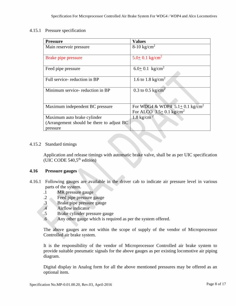
4.15.1 Pressure specification
Pressure Values
Main reservoir pressure
8-10 kg/cm2
Brake pipe pressure
5.0+ 0.1 kg/cm2
Feed pipe pressure
6.0+ 0.1 kg/cm2
Full service- reduction in BP
1.6 to 1.8 kg/cm2
Minimum service- reduction in BP
0.3 to 0.5 kg/cm2
Maximum independent BC pressure
For WDG4 & WDP4 5.1+ 0.1 kg/cm2
For ALCO 3.5+ 0.1 kg/cm2
Maximum auto brake cylinder
(Arrangement should be there to adjust BC
pressure
1.8 kg/cm 2
4.15.2 Standard timings
Application and release timings with automatic brake valve, shall be as per UIC specification
(UIC CODE 540,5th edition)
4.16 Pressure gauges
4.16.1 Following gauges are available in the driver cab to indicate air pressure level in various
parts of the system.
.1 MR pressure gauge
.2 Feed pipe pressure gauge
.3 Brake pipe pressure gauge
.4 Airflow indicator
.5 Brake cylinder pressure gauge
.6 Any other gauge which is required as per the system offered.
The above gauges are not within the scope of supply of the vendor of Microprocessor
Controlled air brake system.
It is the responsibility of the vendor of Microprocessor Controlled air brake system to
provide suitable pneumatic signals for the above gauges as per existing locomotive air piping
diagram.
Digital display in Analog form for all the above mentioned pressures may be offered as an
optional item.
Specification For Microprocessor Controlled Air Brake System For WDG4 / WDP4 and Alco Locomotives
Specification No.MP-0.01.00.20, Rev.03, April-2016
Page 9 of 17
4.17 Air Flow Indicator
Locomotive is provided with air flow indicating device (indicator gauge) to show air flow to
the brake pipe. It is the responsibility of the vendor of Microprocessor Controlled air brake
system to provide suitable pneumatic signals for the above flow indicator as per existing
locomotive air piping diagram. The gauge indicates normal as well as abnormal/excessive air
flow to the brake pipe. Air flow indicator is not part of scope of supplier of microprocessor
air brake system.
4.18 Banking Operation
4.18.1 The brake system shall have necessary provision for using these locomotives as banking
locomotives.
4.18.2 When locomotive is used for banking operation it should not be possible to charge / release
the brakes from banking locomotive. However, it should be possible to apply emergency
brakes on the train, if required, by the banking driver.
4.18.3 It shall be possible to apply & release locomotive independent brakes of bankers.
4.19 Dead Engine Feature
While hauling a dead locomotive as a trailing locomotive, provision shall be made for
application and release of brakes on this locomotive from the leading locomotive. While
hauling a dead locomotive as a piped vehicle (MU pipe not connected), provision shall be
made for application and release of brakes with the help of distributor valve on this
locomotive.
4.20 Loss of Power Feature
With voltage supply feed to Microprocessor Controlled air brake system getting disrupted
there should be facility to apply brakes on train and locomotive by dropping brake pipe
pressure.
4.21 Bail off Feature (Quick Release)
Release of an Automatic locomotive brake while retaining the train brake cylinder pressure
can be accomplished by lifting the bail off ring on the independent valve handle. Locomotive
brake will remain released unless the automatic handle is in emergency. In this case brakes
will reapply when the bail off ring is released.
4.22 Interface with Locomotive Microprocessor
WDG4/WDP4 Locomotives are fitted with EM 2000 family microprocessor control of M/s
EMD (or its equivalent designed by M/s Medha or Siemens) and ALCO Locomotive is fitted
with microprocessor controls to RDSO specification no. MP.0.24.00.26 (latest revision). It is
Specification For Microprocessor Controlled Air Brake System For WDG4 / WDP4 and Alco Locomotives
Specification No.MP-0.01.00.20, Rev.03, April-2016
Page 10 of 17
the responsibility of the successful tenderer of Microprocessor Controlled air brake system
to interface with locomotive microprocessor control system using RS 485 input/output
electrical and communication interface and preferably an Memorandum of Understanding
with manufacturer(s) of Loco microprocessor control to this effect shall be submitted by the
tenderer . RDSO may be approached to facilitate the process.
4.23 Interfacing with Piping and Wiring
Interfacing with Piping and Wiring of the locomotive shall be responsibility of the vendor of
Microprocessor Controlled air brake system.
4.24 Major overhauling of locomotives would be done in six years. Microprocessor Controlled air
brake system should be capable of working for six years without major overhauling.
4.25 Compatibility with Distributed Power System
Purchaser has option to install distributed power system on the locomotive in future. In such
cases the Microprocessor Controlled air brake system shall be fully compatible. The vendor
will provide complete details.
5. ADDITIONAL REQUIREMENTS OF BRAKE SYSTEM
In addition to the basic technical requirements given in para 4, following additional features
should also be incorporated in the Microprocessor Controlled air brake system being offered:
5.1 Multi-Resetting Vigilance Control Device
VCD feature is provided as a part of microprocessor based loco control system (LCC). But it
is the responsibility of the supplier of microprocessor control air brake system to interface
with vigilance feature of locomotive microprocessor based control systems (LCC) as
mentioned in para 4.22.
5.2 Automatic switching ‘ON’ of flasher light
5.2.1 Flasher lights have been provided with on both the sides of diesel locomotives to give
indication of abnormal condition to driver of the train coming from other direction.
5.2.2 The flasher light will low automatically in the direction of train movement in the following
emergency / abnormal situations on the train.
.1 Parting of a train
.2 Emergency brake application by D1 Emergency Valve
5.2.3 The flasher light would not glow automatically in the following condition
.1 Brake application and release by driver
.2 Alarm Chain Pulling
Specification For Microprocessor Controlled Air Brake System For WDG4 / WDP4 and Alco Locomotives
Specification No.MP-0.01.00.20, Rev.03, April-2016
Page 11 of 17
Flasher light is provided as a part of microprocessor based loco control system (LCC). But it
is the responsibility of the supplier of microprocessor control air brake system to provide
suitable signals for flasher light operation to locomotive microprocessor based control
systems (LCC) as mentioned in para 4.22.
6. SCOPE OF SUPPLY
6.1 The scope of supply for complete system would be similar/equivalent to that of existing CCB
1.5 system as per Annexure-A attached.
6.2 The following items shall not be in the scope of supply
i Assistant Driver’s Emergency Brake Valve (para 4.5.5)
ii Air Flow Indicator (para 4.16)
iii Auto Flasher light (par 5.3)
iv Pressure Gauge (para 4.15)
Although the above items are not included in scope of supply, but interfacing with
microprocessor control air brake system is essential. Vendor of microprocessor control air
brake system should make detailed study of the above items for interfacing purpose.
7. LITERATURE AND DRAWINGS
7.1 The tenderer shall submit brake schematic diagram alongwith description of the complete
system with the offer. Pamphlets covering schematic diagram, installation drawing of
complete system shall be submitted along with the offer for proper appreciation of the system
offered by the vendor.
7.2 The tenderer shall submit testing procedure, specification etc. for different valves and brake
system as a whole. The tenderer shall also indicate the maintenance facilities required for
proper upkeep of the equipment. Offer should also include requirements of spares along
with cost of each item for a period of 8 years. The cost of spares will also be given in the
offer.
7.3 After the system is finalised, the tenderer shall submit copies of the instructional,
maintenance and test specifications at the rate of one copy per two locomotive covering the
following:
.1 Assembly drawings of various components and schematic diagram with description
of individual item and system as a whole.
.2 Assembly and disassembly instructions
.3 Trouble shooting instructions
.4 Testing procedure / specification of individual item
.5 Overhauling kit of Valves
.6 Overall dimensions and mounting details of individual items
.7 Particulars of cable entry, if any.
Specification For Microprocessor Controlled Air Brake System For WDG4 / WDP4 and Alco Locomotives
Specification No.MP-0.01.00.20, Rev.03, April-2016
Page 12 of 17
.8 Weight of various components
.9 Lubrication chart (equivalent indigenous lubricant may be indicated).
8 INSPECTION, TESTING AND APPROVAL
8.1 During the developmental stage, for proper control & monitoring, RDSO will be the
Controlling Agency. The supplier shall submit its offer of equipment to RDSO along with all
the details of equipment as per clause 8. The firm will be inspected to check capacity and
capability as per information given in form No MPF 0002 (latest version ) and Annexure A
of specification no. MP-.0.01.00.20, Rev.2, April 2010 of RDSO. Manufacturer will be in
constant touch with RDSO for design review and prototype development. If found suitable
product will be taken up further for prototype inspection.
8.2 Prototype inspection
8.2.1 The prototype inspection including stage inspection will be carried out by representative of
Motive Power Dte. of RDSO/Lucknow at manufacturer’s premises. In general the inspection
will be carried out according to UIC/RDSO specifications. Detailed type tests inspection
scheme will be submitted by the vendor. The test scheme should include testing of complete
system as well as testing of individual brake valve/equipment. The test scheme should
indicate stage inspection and final inspection on test bench as well as on locomotive. Vendor
should get prior approval of test scheme from RDSO before actually conducting prototype
inspection.
8.2.2 There should be proper test equipment/test racks at manufacturer work’s premises to conduct
such tests. The vendor shall provide, without extra charges material, tools and any other
assistance which the purchaser may consider necessary for any test, examination and
dimensional checking.
8.2.3 The vendor shall, on demand make available manufacturing drawings and specifications to
the inspecting authority at the time of inspection. Vendor will also submit the test results of
the test conducted by them.
8.2.4 During prototype inspection manufacturer certificates of components/valves/equipment
which have been purchased from outside shall be produced as a proof of quality assurance.
8.2.5 Electronic equipment used in the system shall be tested in accordance with IEC-60571. These
tests as per relevant clause of IEC-60571 shall be carried out for prototype only. A certificate
(original) from NABL accredited testing laboratory shall be considered satisfactory for this
purpose.
8.3 Inspection of fitment of the brake system on locomotive.
8.3.1 The installation of first system on diesel locomotive shall be the responsibility of the vendor.
Assistance with regard to labour and other facility which are available in the production
unit/work shop/diesel shed of Indian Railways would however, be provided to the vendor
Specification For Microprocessor Controlled Air Brake System For WDG4 / WDP4 and Alco Locomotives
Specification No.MP-0.01.00.20, Rev.03, April-2016
Page 13 of 17
during prototype installation. Vendor will provide all necessary guidance and technology
including any special tooling or wiring etc. required for satisfactory installation of the
system on the locomotive.
8.3.2 The fitment aspect of the system will be checked on the locomotive by the representative of
Motive Power Dte./ RDSO/Lucknow and purchaser in presence of the vendor. It is the
responsibility of the vendor of Microprocessor Controlled air brake system to interface with
locomotive microprocessor control system. The inspection on locomotive will be carried out
generally in accordance with vendor’s test plan which shall be approved by RDSO prior to
testing.
8.4 After successful prototype development and testing, development order will be placed. The
performance of the brake system in field will be monitored for at least two years. On
satisfactory performance in field, the vendor will be placed in category-II of RDSO Vendor
Directory.
8.5 Upgradation from part-II to part-I, the firm should meet qualifying criteria as laid down in
‘Guidelines for Vendor Approval No. MPG 0002(latest version).
8.6 Regular inspection
Regular inspection of the equipment shall be carried out by the purchaser or his nominee.
The supplier shall provide, without extra charges, for material, equipment, tools and any
other assistance, which the purchaser or his nominee may consider necessary for any test and
examination. The supplier shall make available manufacturing drawings and material
specifications of the components to the inspecting authority at the time of inspection.
Supplier will offer brake system for inspection after complete checking by them. The test
results of every brake system will be submitted to the inspecting authority. Inspecting
authority shall carry out all tests necessary to prove that the equipment fulfils the technical
requirements, covered in this specification. However, NYT-1397 tests are mandatory.
9 PERFORMANCE GUARANTEE
The equipment supplied by the vendor shall guarantee the equipment against design and
manufacturing defects for a period of two years from the date of commissioning or 30
months from date of supply which ever is earlier. Not withstanding anything that may be
specified in this specification, the final responsibility for suitability of the design shall lie
with the vendor who shall undertake to carry out all modifications and alterations to
equipment supplied by them for satisfactory functioning in accordance with this specification
as may be necessary during guarantee period. Such modification shall be carried out on all
units by the vendor free of cost.
Any damage or unsatisfactory performance of any equipment noticed during the guarantee
period shall be rectified or replaced free of cost. If replaced component gives unsatisfactory
performance in service, it shall be replaced by modified and improved component by the

Specification For Microprocessor Controlled Air Brake System For WDG4 / WDP4 and Alco Locomotives
Specification No.MP-0.01.00.20, Rev.03, April-2016
Page 14 of 17
vendor free of cost.
10. AFTER SALE SERVICE
The vendor shall post one of their engineers in the base shed where such equipment is
installed for a period of one year after installation and it shall be the responsibility of the
vendor for satisfactory operation of the equipment for this period. Indian Railways
maintenance staff shall be associated with the vendor’s engineer throughout this period. The
engineer would impart necessary training to the maintenance and operation staff free of cost.
11. INDIGENISATION
In case the offered system is being manufactured in country other than India, vendor shall
arrange for manufacture of equipment in India by transferring the technology to a suitable
organization in India. The vendor will give stage wise details of indigenization programme.
12. DEVIATIONS
12.1 The vendor shall submit clause wise comments from the specification and shall indicate the
deviations, if any with the reasons thereof.
12.2 Any deviation from the standards laid down in this specification, with a view to improve the
performance of the equipment shall be given with details. Supporting documents for such
suggestion shall also be given with the offer.
13. TRAINING
13.1 Sufficient number of technicians / engineers /officers shall be trained in consultations with
the purchaser / RDSO so that adequate staff is available in the field for maintenance. This
training shall be at the vendor works and diesel sheds for a suitable period and shall cover
maintenance and testing, brake system and design, quality control and trouble shooting.
13.2 Adequate numbers of maintenance manual covering schedule maintenance, maintenance
practices, testing, maintenance tools, spare etc and wall charts showing pictorial view of
components along with part numbers will be given. These maintenance manuals and wall
charts are meant for wider circulation for Railways and fresh copies will be given with each
order even if there are no changes in the design.
14. QUALITY ASSURANCE PLAN (QAP)
The firm will give a quality assurance programme (QAP) for approval to RDSO. QAP will
consist of following aspects-
.1 Organisation chart emphasising quality control set-up.
.2 Qualification of key personals and the officials deployed in quality control cell.
.3 Process flow chart indicating process of manufacture for an individual product or for
a family of products if the process is same.
Specification For Microprocessor Controlled Air Brake System For WDG4 / WDP4 and Alco Locomotives
Specification No.MP-0.01.00.20, Rev.03, April-2016
Page 15 of 17
.4 Stage inspection detailing inspection procedure, inspection parameters, method of
testing/test procedure including sample sizes for destructive and non-destructive
testing etc.
.5 Details of sublet vendors-
- The name of components for which it is approved.
- Sublet vendor approving agency.
- Inspection criteria at sublet vendor’s premises.
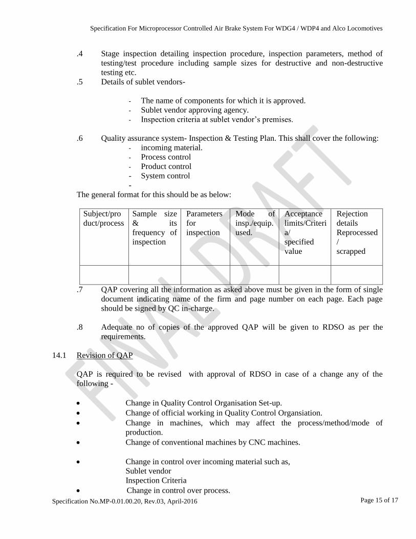
.6 Quality assurance system- Inspection & Testing Plan. This shall cover the following:
- incoming material.
- Process control
- Product control
- System control
-
The general format for this should be as below:
Subject/pro
duct/process
Sample size
& its
frequency of
inspection
Parameters
for
inspection
Mode of
insp./equip.
used.
Acceptance
limits/Criteri
a/
specified
value
Rejection
details
Reprocessed
/
scrapped
.7 QAP covering all the information as asked above must be given in the form of single
document indicating name of the firm and page number on each page. Each page
should be signed by QC in-charge.
.8 Adequate no of copies of the approved QAP will be given to RDSO as per the
requirements.
14.1 Revision of QAP
QAP is required to be revised with approval of RDSO in case of a change any of the
following -
Change in Quality Control Organisation Set-up.
Change of official working in Quality Control Organsiation.
Change in machines, which may affect the process/method/mode of
production.
Change of conventional machines by CNC machines.
Change in control over incoming material such as,
Sublet vendor
Inspection Criteria
Change in control over process.
Specification For Microprocessor Controlled Air Brake System For WDG4 / WDP4 and Alco Locomotives
Specification No.MP-0.01.00.20, Rev.03, April-2016
Page 16 of 17
Change in control over product.
Change in control over system.
Addition of any corrective action taken to improve the system by the
vendor.
Alterations suggested by RDSO in the intervening period since last approval.

Specification For Microprocessor Controlled Air Brake System For WDG4 / WDP4 and Alco Locomotives
Specification No.MP-0.01.00.20, Rev.03, April-2016
Page 17 of 17
Annexure - A
The existing Scope of Supply comprises the following items:
S.No DLW Part No. EMD Part No. Description Qty.
per
set
1. 17061805 10633678 Brake Controller to Knorr Pt.No.
774902
2
2. 17450433 10631944 Electronic Brake rack to Knorr Pt.No.
775002
1
3. 18011020 10634104 Cable ASM CRU to Controller
CRU-BVC1 to Knorr Pt.No.
775286
1
4. 18011019 10634660 Cable ASM CRU to Controller
CRU-BVAE1 to Knorr Pt.No.
775300
1
5. 18010982 10634659 Cable ASM CRU to Controller
CRU-BVC2 to Knorr Pt.No.
775287
1
6. 18011007 1063469 Cable ASM CRU to Controller
CRU-BVAE2 to Knorr Pt.No.
7752301
1
7. 18011032 10634105 Fibre Optic Cable CRU to BVC1
to Knorr Pt.No. 77
1
8. 18010994 10634230 Fibre Optic Cable CRU to BVC2
to Knorr Pt.No. 775218
1
9. 17454402 - Auxiliary Reservoir to Knorr Pt.No.
775219
1
10. 17454414 P.T No. 769951 CRU-CRJ9 1
11. 17454426 P.T No. 775158 CRU-CRJ10 1
12. 17454438 P.T No. 775521 CRU-CRJ11 1
13. 17454440 P.T No. 775162 VCU-VCJ1 1
Scope of supply should comprise following items or their equivalents:
Note:
1. In case exact equivalent is not offered, functional equivalent must be offered. The total no. of
items comprising the microprocessor controlled air brake system may be more or less than
the existing system provided that the existing locations for mounting of one no. Brake rack
and two nos brake controllers are followed.
2. Dimension of the offered items should not exceed the dimensions of the corresponding items
of existing CCB 1.5 system. In case any dimensions of offered items exceeds the
corresponding dimension of existing item, vendor must ensure the sufficient space is
available on the locomotive and submit details along with the offer.
3. Mounting arrangements, piping and wiring connection etc. should be interchangeable with
existing system as for as possible.