Embed Size (px)
Citation preview
GEKKO
PAUT fl aw detector
64:64 parallel channels + 4 additional TOFD/conventional UT channels International code compliance: ASME, AWS, API, ASTM, ISO-EN
Advanced features
Real-time and Adaptive TFMLinear, Matrix, Dual Linear and Dual Matrix arrays 3 axis management 3D imaging3D real time imagingCylindrical reconstruction
Field ready
10.4‘’ Resistive touch screenDust & water resistantHot swap batteryMulti-group applications
User-friendly
All-level operatorsStep-by-step application Calibration wizardsAnalysis and reporting tools
A WIDE RANGE OF APPLICATION
Weld inspection . Pressure vessel inspection . Blistering characterization . Pipeline girth welds inspection . Small diameter pipes . Corrosion mapping . Nozzle inspection . Composite inspection . Cladded weld inspection . Fillet weld inspection
PHASED-ARRAY FLAW DETECTOR FOR FIELD INSPECTIONS
PHASED-ARRAY FLAW DETECTOR
Rail inspectionWeld inspection Aircraft wing inspection Corrosion mapping
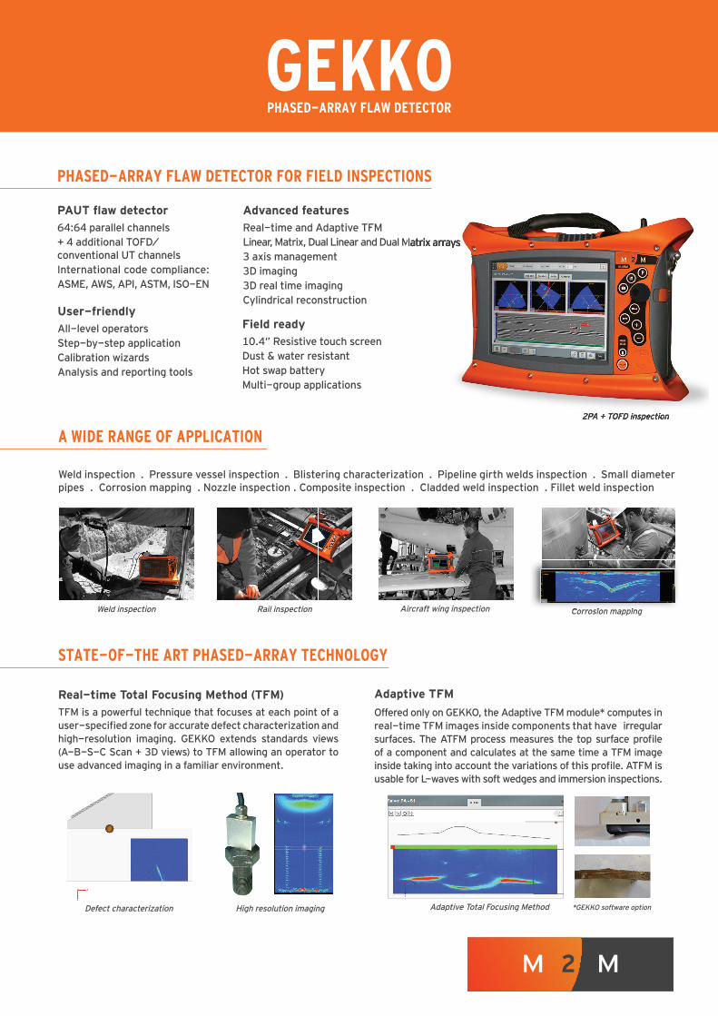
2PA + TOFD inspection
Corrosion mapping
STATE-OF-THE ART PHASED-ARRAY TECHNOLOGY
Adaptive TFM
Offered only on GEKKO, the Adaptive TFM module* computes in real-time TFM images inside components that have irregular surfaces. The ATFM process measures the top surface profi le of a component and calculates at the same time a TFM image inside taking into account the variations of this profi le. ATFM is usable for L-waves with soft wedges and immersion inspections.
Real-time Total Focusing Method (TFM)
TFM is a powerful technique that focuses at each point of a user-specifi ed zone for accurate defect characterization and high-resolution imaging. GEKKO extends standards views (A-B-S-C Scan + 3D views) to TFM allowing an operator to use advanced imaging in a familiar environment.
High resolution imagingDefect characterization Adaptive Total Focusing Method *GEKKO software option
Linear, Matrix, Dual Linear and Dual Matrix arrays
2PA + TOFD inspection
GEKKO
Indicated values may change without notice. *Standard: EN ISO 18563-1 for phased array channels**Standard: EN ISO 12668-1 for conventional channels
generalL x W x H: 410mm x 284mm x 126mm 10.4‘’ high contrast resistiv e screen - resolution 1024x768 pxOperating temperature range: f rom -10°C to 45°C | 14°F to 113°F Weight: 6kg (without battery ) ; 0,480g /batteryStorage temperature range: -10°C to 60°C | 14°F to 140°F with battery IP66Operating time: 4h (hot swappable battery ) Shock resistance according to MIL-STD-810G
I-O1 IPEX connector f or phased-array (can be upgraded to 2 with splitter) 4 LEMO 00 connectors f or conv entional UT3 encoder inputs 1 external trigger3 USB 2.0 Acquisition f ile transf er through Ethernet
16 analog inputs
analysisCapture © sof tware with analy sis and reporting tools – Free v iewer Amplitude range: up to 800%A-Scan, B-Scan, C-Scan, D-Scan, Echody namic, Top v iew, Side v iew, 3D v iew Ov erlay part geometry : plate, cy linder, T or Y section, nozzleAnaly sis gates Ov erlay weld geometry Compatibility with CIVA analy sis and ENLIGHT Customizable inspection report
acquisitionHardware acquisition gates Max. data f low 150 MB/s on a 128Gb SSD (extensible up to 1 To)A-Scan/Peak data recording Inspection data f ile size: up to 10GbFMC recording Data transf er through EthernetAcquisition trigger on time, ev ent, encoder 800% amplitude range
pulsers64 phased-array channels*: 4 UT-TOFD channels**:Negativ e square pulse, width: 35ns to 1250ns Negativ e square pulse, width: 30ns to 1250nsVoltage: 12V – 100V with 1V step Voltage: 12V to 200V with 1V stepMax. PRF: up to 20kHz Max. PRF: up to 20kHz
real-time TFMReconstruction channels: up to 64 Max number of points of reconstructed image: up to 65kMax ref resh rate: up to 80f ps Sound paths: direct (L or S), indirect and conv erted modes
standard phased-arrayLinear scanning, sectorial scanning, compound scanning Linear, matrix, DLA and DMA probesMaximum activ e aperture: 64 channels Up to 6 probes | Up to 8 groups | Up to 2,048 delay -lawsPhased array computation delay laws on plate, cy linder, T & Y, nozzle CIVA f ueled phased-array calculatorFocusing mode: true depth, sound path, projection
wizardsCAD ov erlay and 3D v iew Scanner calibrationReal-time phased array calculator Amplitude calibration (TCG, DAC, DGS)Base-time calibration f or conv entional UT Probe design | Weld geometry designWedge calibration (angle, height, v elocity ) Amplitude balancingSpecimen v elocity calibration Part geometry with parametric shapes: plate, cy linder, T & Y, nozzle
digitizerDigitizing and real-time summation on 64 channels Resolution: 16bitsFIR f ilters Max. sampling f requency : 100 MHzReal-time av eraging up to x32 Digitizing depth up to 16k pointsRectif ied, RF, env elope A-scan range or delay max 65k points
receivers64 phased-array channels*: 4 UT-TOFD channels**:Input impedance: 50 Ω Input impedance: 50 ΩFrequency range: 0.4 to 20MHz Frequency range: 0.6 to 25MHzMax. input signal: 2Vpp | TCG – ACG – DGS calibration wizard | DGS Max. input signal: 2VppGain: up to 120dB (0.1dB step) TCG – DAC calibration wizard Cross-talk between two channels < 50 dB Gain: up to 120dB (0.1dB step)
© 2
017
M2M
. All
right
s re
serv
ed. G
EKKO
is a
regi
ster
ed tr
adem
ark
of M
2M c
ompa
ny. T
hese
spe
cifi c
atio
ns a
re re
ferri
ng to
GEK
KO v
ersi
on 2
.1.
M2M t. +33 (0)1 60 92 39 65 f. +33 (0)1 60 92 57 31 [email protected] w w w. m 2 m - n d t . c o m
1 rue de Terre-NeuveBât. H. Miniparc du VergerZ A C o u r t a b e u f91940 Les Ulis. France