Embed Size (px)
Citation preview

30
CHAPTER OUTLINE
30.1 The Biot-Savart Law30.2 The Magnetic Force Between Two Parallel Conductors30.3 Ampère’s Law30.4 The Magnetic Field of a Solenoid30.5 Magnetic Flux30.6 Gauss’s Law in Magnetism30.7 Displacement Current and the General Form of Ampère’s Law
30.9 The Magnetic Field of the
30.8 Magnetism in Matter
Earth
Sources of the Magnetic Field
ANSWERS TO QUESTIONS
Q30.1 It is not. The magnetic field created by a single loop of currentresembles that of a bar magnet—strongest inside the loop, anddecreasing in strength as you move away from the loop.Neither is it in a uniform direction—the magnetic field linesloop though the loop!
Q30.2 No magnetic field is created by a stationary charge, as the rateof flow is zero. A moving charge creates a magnetic field.
Q30.3 The magnetic field created by wire 1 at the position of wire 2 isinto the paper. Hence, the magnetic force on wire 2 is indirection down × into the paper = to the right, away from wire1. Now wire 2 creates a magnetic field into the page at thelocation of wire 1, so wire 1 feels force up ×into the paper = left,away from wire 2.
FIG. Q30.3
185

186 Sources of the Magnetic Field
Q30.4 No total force, but a torque. Let wire one carry current in the ydirection, toward the top of the page. Let wire two be a millimeterabove the plane of the paper and carry current to the right, in the xdirection. On the left-hand side of wire one, wire one creates magneticfield in the z direction, which exerts force in the i k j× = − direction onwire two. On the right-hand side, wire one produces magnetic field in
the −k direction and makes a i k j× − = +e j force of equal magnitude act
on wire two. If wire two is free to move, its center section will twistcounterclockwise and then be attracted to wire one.
1
2
FIG. Q30.4
Q30.5 Ampère’s law is valid for all closed paths surrounding a conductor, but not always convenient.There are many paths along which the integral is cumbersome to calculate, although not impossible.Consider a circular path around but not coaxial with a long, straight current-carrying wire.
Q30.6 The Biot-Savart law considers the contribution of each element of current in a conductor todetermine the magnetic field, while for Ampère’s law, one need only know the current passingthrough a given surface. Given situations of high degrees of symmetry, Ampère’s law is moreconvenient to use, even though both laws are equally valid in all situations.
Q30.7 If the radius of the toroid is very large compared to its cross-sectional area, then the field is nearlyuniform. If not, as in many transformers, it is not.
Q30.8 Both laws use the concept of flux—the “flow” of field lines through a surface to determine the fieldstrength. They also both relate the integral of the field over a closed geometrical figure to afundamental constant multiplied by the source of the appropriate field. The geometrical figure is asurface for Gauss’s law and a line for Ampère’s.
Q30.9 Apply Ampère’s law to the circular path labeled 1 in the picture. Since there is nocurrent inside this path, the magnetic field inside the tube must be zero. On theother hand, the current through path 2 is the current carried by the conductor.Therefore the magnetic field outside the tube is nonzero.
FIG. Q30.9
Q30.10 The magnetic field inside a long solenoid is given by BNI
=µ 0 .
(a) If the length is doubled, the field is cut in half.
(b) If N is doubled, the magnetic field is doubled.
Q30.11 The magnetic flux is ΦB BA= cosθ . Therefore the flux is maximum when B is perpendicular to theloop of wire. The flux is zero when there is no component of magnetic field perpendicular to theloop—that is, when the plane of the loop contains the x axis.

Chapter 30 187
Q30.12 Maxwell included a term in Ampère’s law to account for the contributions to the magnetic field bychanging electric fields, by treating those changing electric fields as “displacement currents.”
Q30.13 M measures the intrinsic magnetic field in the nail. Unless the nail was previously magnetized, thenM starts out from zero. H is due to the current in the coil of wire around the nail. B is related to thesum of M and H. If the nail is aluminum or copper, H makes the dominant contribution to B, but Mcan add a little in the same or in the opposite direction. If the nail is iron, as it becomes magnetizedM can become the dominant contributor to B.
Q30.14 Magnetic domain alignment creates a stronger external magnetic field. The field of one piece of ironin turn can align domains in another iron sample. A nonuniform magnetic field exerts a net force ofattraction on magnetic dipoles aligned with the field.
Q30.15 The shock misaligns the domains. Heating will also decrease magnetism.
Q30.16 Magnetic levitation is illustrated in Figure Q30.31. The Earth’s magnetic field is so weak that thefloor of his tomb should be magnetized as well as his coffin. Alternatively, the floor of his tomb couldbe made of superconducting material, which exerts a force of repulsion on any magnet.
Q30.17 There is no magnetic material in a vacuum, so M must be zero. Therefore B H= µ0 in a vacuum.
Q30.18 Atoms that do not have a permanent magnetic dipole moment have electrons with spin and orbitalmagnetic moments that add to zero as vectors. Atoms with a permanent dipole moment haveelectrons with orbital and spin magnetic moments that show some net alignment.
Q30.19 The magnetic dipole moment of an atom is the sum of the dipole moments due to the electrons’orbital motions and the dipole moments due to the spin of the electrons.
Q30.20 M and H are in opposite directions. Section 30.8 argues that all atoms should be thought of asweakly diamagnetic due to the effect of an external magnetic field on the motions of atomicelectrons. Paramagnetic and ferromagnetic effects dominate whenever they exist.
Q30.21 The effects of diamagnetism are significantly smaller than those of paramagnetism.
Q30.22 When the substance is above the Curie temperature, random thermal motion of the moleculesprevents the formation of domains. It cannot be ferromagnetic, but only paramagnetic.
Q30.23 A ferromagnetic substance is one in which the magnetic moments of the atoms are aligned withindomains, and can be aligned macroscopically. A paramagnetic substance is one in which themagnetic moments are not naturally aligned, but when placed in an external magnetic field, themolecules line their magnetic moments up with the external field. A diamagnetic material is one inwhich the magnetic moments are also not naturally aligned, but when placed in an externalmagnetic field, the molecules line up to oppose the external magnetic field.
Q30.24 (a) B increases slightly
(b) B decreases slightly
(c) B increases significantly
Equations 30.33 and 30.34 indicate that, when each metal is in the solenoid, the total field isB H= +µ χ0 1b g . Table 30.2 indicates that B is slightly greater than µ 0H for aluminum and slightly lessfor copper. For iron, the field can be made thousands of times stronger, as seen in Example 30.10.
188 Sources of the Magnetic Field
Q30.25 A “hard” ferromagnetic material requires much more energy per molecule than a “soft”ferromagnetic material to change the orientation of the magnetic dipole moments. This way, a hardferromagnetic material is more likely to retain its magnetization than a soft ferromagnetic material.
Q30.26 The medium for any magnetic recording should be a hard ferromagnetic substance, so that thermalvibrations and stray magnetic fields will not rapidly erase the information.
Q30.27 If a soft ferromagnetic substance were used, then the magnet would not be “permanent.” Anysignificant shock, a heating/cooling cycle, or just rotating the magnet in the Earth’s magnetic fieldwould decrease the overall magnetization by randomly aligning some of the magnetic dipolemoments.
Q30.28 You can expect a magnetic tape to be weakly attracted to a magnet. Before you erase the informationon the tape, the net magnetization of a macroscopic section of the tape would be nearly zero, as thedifferent domains on the tape would have opposite magnetization, and be more or less equal innumber and size. Once your external magnet aligns the magnetic moments on the tape, there wouldbe a weak attraction, but not like that of picking up a paper clip with a magnet. A majority of themass of the tape is non-magnetic, and so the gravitational force acting on the tape will likely belarger than the magnetic attraction.
Q30.29 To magnetize the screwdriver, stroke one pole of the magnet along the blade of the screwdriverseveral or many times. To demagnetize the screwdriver, drop it on a hard surface a few times, orheat it to some high temperature.
Q30.30 The north magnetic pole is near the south geographic pole. Straight up.
Q30.31 (a) The magnets repel each other with a force equal to the weight of one of them.
(b) The pencil prevents motion to the side and prevents the magnets from rotating under theirmutual torques. Its constraint changes unstable equilibrium into stable.
(c) Most likely, the disks are magnetized perpendicular to their flat faces, making one face anorth pole and the other a south pole. One disk has its north pole on the top side and theother has its north pole on the bottom side.
(d) Then if either were inverted they would attract each other and stick firmly together.
SOLUTIONS TO PROBLEMS
Section 30.1 The Biot-Savart Law
P30.1 BI
R
q v R
R= = =
µ µ π0 0
2
2
212 5
b g. T
P30.2 BIR
= =× ⋅ ×
= × =−
−µπ
π
πµ0
7 45
2
4 10 1 00 10
2 1002 00 10 20 0
T m A A
m T T
e je ja f
.. .

Chapter 30 189
P30.3 (a) BIa
= −FHG
IKJ
44 4
34
0µπ
π πcos cos where a =
2
is the distance from any side to the center.
B =×
+FHG
IKJ = × =
−−4 00 10
0 2002
22
22 2 10 28 3
65.
.. T T into the paperµ
(b) For a single circular turn with 4 2= π R ,
BI
RI
= = =×
=−
µ µ π πµ0 0
2 7
2 4
4 10 10 0
4 0 40024 7
e ja fa f
.
.. T into the paper
FIG. P30.3
P30.4 BIr
= =×
= ×−
−µπ
π
π0
77
2
4 10 1 00
2 1 002 00 10
e ja fa f
.
..
A
m T
P30.5 For leg 1, ds r× = 0 , so there is no contribution to the field from thissegment. For leg 2, the wire is only semi-infinite; thus,
BIx
Ix
=FHGIKJ =
12 2 4
0 0µπ
µπ
into the paper .
FIG. P30.5
P30.6 We can think of the total magnetic field as the superposition of the field due to the long straight wire
(having magnitude µπ
0
2IR
and directed into the page) and the field due to the circular loop (having
magnitude µ0
2I
R and directed into the page). The resultant magnetic field is:
B = +FHGIKJ1
12
0
πµ I
R directed into the pageb g .
P30.7 For the straight sections ds r× = 0 . The quarter circle makes one-fourth the field of a full loop:
B = =14 2 8
0 0µ µIR
IR
into the paper B =× ⋅
=−4 10 5 00
8 0 030 026 2
7πµ
T m A A
m T into the paper
e ja fb g
.
..

190 Sources of the Magnetic Field
P30.8 Along the axis of a circular loop of radius R,
BIR
x R=
+
µ 02
2 2 3 22e j
orBB x R0
2
3 2
1
1=
+
LNMM
OQPPb g
where BI
R00
2≡
µ.
FIG. P30.8
x R B B0
0.00 1.001.00 0.3542.00 0.08943.00 0.03164.00 0.01435.00 0.00754
*P30.9 Wire 1 creates at the origin magnetic field
B10
2=
µπ
Ir
right hand rule =µ
π0 1
2Ia
=µ
π0 1
2Ia
j
(a) If the total field at the origin is 22 2
0 1 0 12
µπ
µπ
Ia
Ia
j j B= + then the second wire must create field
according to B j20 1 0 2
2 2 2= =
µπ
µπ
Ia
Iaa f .
Then I I I2 1 12 2= = out of the paper k .
(b) The other possibility is B B j j B1 20 1 0 1
222 2
+ = − = +µπ
µπ
Ia
Iae j . Then
B j20 1 0 23
2 2 2= − =
µπ
µπ
Ia
Iae j a f I I I2 1 16 6= = − into the paper ke j
*P30.10 Every element of current creates magnetic field in the same direction, into the page, at the center ofthe arc. The upper straight portion creates one-half of the field that an infinitely long straight wirewould create. The curved portion creates one quarter of the field that a circular loop produces at its
center. The lower straight segment also creates field 12 2
0µπ
Ir
.
The total field is
B = + +FHG
IKJ = +FHG
IKJ
= FHGIKJ
12 2
14 2
12 2 2
1 14
0 284 15
0 0 0 0
0
µπ
µ µπ
µπ
µ
Ir
Ir
Ir
Ir
Ir
into the page into the plane of the paper
into the page..

Chapter 30 191
*P30.11 (a) Above the pair of wires, the field out of the page of the 50 A
current will be stronger than the −ke j field of the 30 A
current, so they cannot add to zero. Between the wires,both produce fields into the page. They can only add tozero below the wires, at coordinate y y= − . Here the totalfield is
B =µπ0
2Ir +
µπ0
2Ir
:
02
500 28
30
50 30 0 28
50 30 0 28
20 30 0 28 0 420
0=+
− +LNMM
OQPP
= +
− = −
− = = −
µπ
A m
A
m
m
m at m
y y
y y
y y
y y
.
.
.
. .
d i e j e j
d ib g b ga f
k k
FIG. P30.11
(b) At y = 0 1. m the total field is B =µπ0
2Ir +
µπ0
2Ir :
B k k k=× ⋅
−− + −
FHG
IKJ = × −
−−4 10
250
0 2830
0 101 16 10
74π
π T m A A
0.10 m A m
T. .
.a f e j e j e j .
The force on the particle is
F v B i k j= × = − × × × × ⋅ ⋅ − = × −− − −q 2 10 150 10 1 16 10 3 47 106 6 4 2 C m s N s C m Ne je je j e je j e j. . .
(c) We require F j E Ee q= × + = = − ×− −3 47 10 2 102 6. N Ce j e j .
So E j= − ×1 73 104. N C .
P30.12 dBI d
r=
×µπ0
24
r
BI a
a
b
b
Ia b
= −FHG
IKJ
= −FHGIKJ
µπ
π π
µ
016
2
16
2
0
42 2
121 1
B directed out of the paper

192 Sources of the Magnetic Field
*P30.13 (a) We use equation 30.4. For the distance a from the wire to
the field point we have tan302
° =a
L, a L= 0 288 7. . One
wire contributes to the field at P
BIa
IL
IL
IL
= − = °− °
= =
µπ
θ θµ
π
µπ
µπ
01 2
0
0 0
4 4 0 288 730 150
1 7324 0 288 7
1 50
cos cos.
cos cos
..
..
b g b g a fa fb g
Each side contributes the same amount of field in the samedirection, which is perpendicularly into the paper in the
picture. So the total field is 31 50 4 500 0. .µ
πµ
πI
LI
LFHG
IKJ = .
aP
θ2
θ1
I
L2
FIG. P30.13(a)
(b) As we showed in part (a), one whole side of the triangle
creates field at the center µ
π0 1 732
4I
a.a f
. Now one-half of one
nearby side of the triangle will be half as far away frompoint Pb and have a geometrically similar situation. Then it
creates at Pb field µ
πµ
π0 01 7324 2
2 1 7324
Ia
Ia
. .a fb g
a f= . The two half-
sides shown crosshatched in the picture create at Pb field
22 1 732
44 1 7324 0 288 7
60 0 0µπ
µπ
µπ
Ia
IL
IL
. ..
a f a fb g
FHG
IKJ = = . The rest of the
triangle will contribute somewhat more field in the samedirection, so we already have a proof that the field at Pb is
stronger .
������������
aPb
FIG. P30.13(b)
P30.14 Apply Equation 30.4 three times:
B
B
= −+
FHG
IKJ +
++
+
FHG
IKJ
+−
+− °
FHG
IKJ
=+ − +FH IK
+
µπ
µπ
µπ
µ
π
02 2
02 2 2 2
02 2
02 2 2 2
2 2
40
4
4180
2
Ia
d
d a
Id
a
d a
a
d a
Ia
d
d a
I a d d a d
ad a d
cos
cos
toward you away from you
toward you
away from you

Chapter 30 193
P30.15 Take the x-direction to the right and the y-direction up in the plane of thepaper. Current 1 creates at P a field
BIa1
07
2
2 00 10 3 00
0 050 0= =
× ⋅−µπ
. .
.
T m A
A me ja f
b gB1 12 0= . Tµ downward and leftward, at angle 67.4° below the –x axis.
Current 2 contributes
B2
72 00 10 3 00
0 120=
× ⋅−. .
.
T m A
A me ja f
a f clockwise perpendicular to 12.0 cm
B2 5 00= . Tµ to the right and down, at angle –22.6°
5.00 cm
13.0 cm
12.0 cm
P
I1
I2
B2B1
FIG. P30.15
Then, B B B i j i j= + = − °− ° + °− °1 2 12 0 67 4 67 4 5 00 22 6 22 6. cos . sin . . cos . sin . T Tµ µb ge j b ge jB j j j= − − = −11 1 1 92 13 0. . . T T Tµ µ µb g b g b g
Section 30.2 The Magnetic Force Between Two Parallel Conductors
P30.16 Let both wires carry current in the x direction, the first at y = 0 and thesecond at y = 10 0. cm .
(a) B k k= =× ⋅−
µπ
π
π0
7
2
4 10 5 00
2 0 100Ir
.
.
T m A A
me ja f
a fB = × −1 00 10 5. T out of the page
y
y = 10.0 cm
I1 = 5.00 A
I2 = 8.00 A
z
x
FIG. P30.16(a)
(b) F B i k jB I= × = × × = × −− −2
5 58 00 1 00 1 00 10 8 00 10. . . . A m T Na f a f e j e je j
FB = × −8 00 10 5. N toward the first wire
(c) B k k k= − =× ⋅
− = × −−
−µπ
π
π0
75
2
4 10 8 00
2 0 1001 60 10
Ir
.
..e j e ja f
a f e j e je j T m A A
m T
B = × −1 60 10 5. T into the page
(d) F B i k jB I= × = × × − = × +− −1
5 55 00 1 00 1 60 10 8 00 10. . . . A m T Na f a f e je j e je j
FB = × −8 00 10 5. N towards the second wire
194 Sources of the Magnetic Field
P30.17 By symmetry, we note that the magnetic forces on the top and bottomsegments of the rectangle cancel. The net force on the vertical segments ofthe rectangle is (using Equation 30.11)
F F F i i
F i
F i
= + =+
−FHG
IKJ =
−+
FHG
IKJ
=× −F
HGIKJ
= − ×
−
−
1 20 1 2 0 1 2
7
5
21 1
2
4 10 5 00 10 0 0 450
20 150
0 250
2 70 10
µπ
µπ
π
π
I Ic a c
I I ac c a
. . . ..
.
a fe ja fa fa f
a fa fe j
N A A A m m0.100 m m
N
2
or F = × −2 70 10 5. N toward the left .FIG. P30.17
*P30.18 To attract, both currents must be to the right. The attraction is described by
F I B IIr
= ° =2 2090
2sin
µπ
So IF r
I20 1
67
2320 10
2 0 5
4 10 2040 0= = ×
× ⋅ ⋅
FHGG
IKJJ =
−−
πµ
π
π N m
m
N s C m A Ae j a f
e ja f.
. FIG. P30.18
Let y represent the distance of the zero-field point below the upper wire.
Then B =µπ0
2Ir +
µπ0
2Ir
02
20 400 5
0= +−
FHG
IKJ
µπ
Aaway
A m
towardy yb g b g a f
.
20 0 5 40. m − =y yb g 20 0 5 60. ma f = y
y = 0 167. m below the upper wire
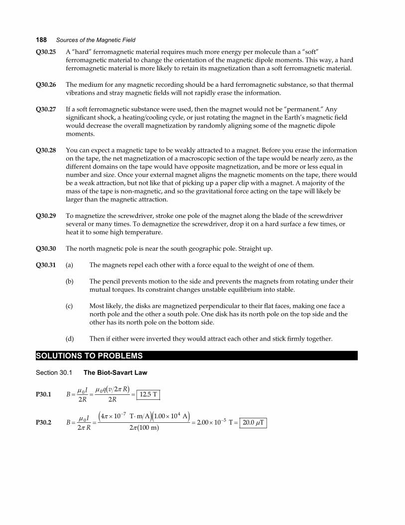
*P30.19 Carrying oppositely directed currents, wires 1 and 2 repeleach other. If wire 3 were between them, it would have torepel either 1 or 2, so the force on that wire could not bezero. If wire 3 were to the right of wire 2, it would feel alarger force exerted by 2 than that exerted by 1, so the totalforce on 3 could not be zero. Therefore wire 3 must be tothe left of both other wires as shown. It must carrydownward current so that it can attract wire 2.
(a) For the equilibrium of wire 3 we have
d 20 cm
Wire 1Wire 3 Wire 2
I3
1.50 A4.00 A
FIG. P30.19
F F1 2 on 3 on 3=µ
πµ
π0 3 0 31 50
24
2 20. A A
cma f a f
a fI
dI
d=
+
1 5 20 4. cm + =d da f d = =30
12 0 cm
2.5 cm to the left of wire 1.
(b) For the equilibrium of wire 1,
µπ
µπ
0 3 01 52 12
4 1 52 20
I . . A cm
A A cm
a fa f
a fa fa f= I3
1220
4 2 40= = A A down.
We know that wire 2 must be in equilibrium because the forces on it are equal in magnitudeto the forces that it exerts on wires 1 and 3, which are equal because they both balance theequal-magnitude forces that 1 exerts on 3 and that 3 exerts on 1.

Chapter 30 195
P30.20 The separation between the wires is
a = ° =2 6 00 8 00 1 67. sin . . cm cma f .
(a) Because the wires repel, the currents are in
opposite directions .
(b) Because the magnetic force acts horizontally,
FF
Iamg
B
g= = °
µπ
02
28 00tan .
Img a2
0
28 00= °
πµ
tan . so I = 67 8. A .
FIG. P30.20
Section 30.3 Ampère’s Law
P30.21 Each wire is distant from P by
0 200 45 0 0 141. cos . . m ma f °= .
Each wire produces a field at P of equal magnitude:
BIaA = =
× ⋅=
−µπ
µ07
2
2 00 10 5 00
0 1417 07
. .
..
T m A A
m T
e ja fa f .
Carrying currents into the page, A produces at P a field of7 07. Tµ to the left and down at –135°, while B creates a fieldto the right and down at – 45°. Carrying currents towardyou, C produces a field downward and to the right at – 45°,while D ’s contribution is downward and to the left. Thetotal field is then
FIG. P30.21
4 7 07 45 0 20 0. sin . . T Tµ µb g ° = toward the bottom of the page
P30.22 Let the current I be to the right. It creates a field BId
=µπ
0
2 at the proton’s location. And we have a
balance between the weight of the proton and the magnetic force
mg qvId
− + − × =j i ke j e j e jµπ
0
20 at a distance d from the wire
dqv I
mg= =
× × × ⋅ ×
×=
− − −
−
µπ
π
π0
19 4 7 6
272
1 60 10 2 30 10 4 10 1 20 10
2 1 67 10 9 805 40
. . .
. ..
C m s T m A A
kg m s cm
2
e je je je je je j

196 Sources of the Magnetic Field
P30.23 From Ampere’s law, the magnetic field at point a is given by BIraa
a=
µπ0
2, where Ia is the net current
through the area of the circle of radius ra . In this case, Ia = 1 00. A out of the page (the current in theinner conductor), so
Ba =× ⋅
×=
−
−
4 10 1 00
2 1 00 10200
7
3
π
πµ
T m A A
m T toward top of page
e ja fe j
.
..
Similarly at point b : BIrbb
b=
µπ0
2, where Ib is the net current through the area of the circle having
radius rb .
Taking out of the page as positive, Ib = − = −1 00 3 00 2 00. . . A A A , or Ib = 2 00. A into the page.Therefore,
Bb =× ⋅
×=
−
−
4 10 2 00
2 3 00 10133
7
3
π
πµ
T m A A
m T toward bottom of page
e ja fe j
.
..
P30.24 (a) In BIr
=µπ0
2, the field will be one-tenth as large at a ten-times larger distance: 400 cm
(b) B k k= + −µπ
µπ
0
1
0
22 2Ir
Ir e j so B =
× ⋅−
FHG
IKJ =
−4 102
10 398 5
10 401 5
7 507π
π T m 2.00 A
A m m nT
a f. .
.
(c) Call r the distance from cord center to field point and 2 3 00d = . mm the distance betweenconductors.
BI
r d r dI d
r d=
−−
+FHG
IKJ = −
µπ
µπ
0 02 22
1 12
2
7 50 10 2 00 10 2 003 00 10
2 25 1010 7
3
2 6. . ..
.× = × ⋅
×
− ×− −
−
− T T m A A m
m2e ja f e jr
so r = 1 26. m
The field of the two-conductor cord is weak to start with and falls off rapidly with distance.
(d) The cable creates zero field at exterior points, since a loop in Ampère’s law encloses zero
total current. Shall we sell coaxial-cable power cords to people who worry about biologicaldamage from weak magnetic fields?
P30.25 (a) One wire feels force due to the field of the other ninety-nine.
BI rR
= =× ⋅ ×
×= ×
− −
−
−µπ
π
π0 0
2
7 2
2 23
2
4 10 99 2 00 0 200 10
2 0 500 103 17 10
T m A A m
mT
e ja fb ge je j
. .
..
This field points tangent to a circle of radius 0.200 cm and exerts forceF B= ×I toward the center of the bundle, on the single hundredth wire:
FIB
FB
= = × ° =
= ×
−
−
sin . . sin .
.
θ 2 00 3 17 10 90 6 34
6 34 10
3
3
A T mN m
N m inward
a fe j
(b) B r∝ , so B is greatest at the outside of the bundle. Since each wirecarries the same current, F is greatest at the outer surface .
FIG. P30.25

Chapter 30 197
P30.26 (a) BNIrinner
T m A A
m T= =
× ⋅ ×=
−µ
π
π
π0
7 3
2
4 10 900 14 0 10
2 0 7003 60
e ja fe ja f
.
..
(b) BNIrouter
T m A A
m T= =
× ⋅ ×=
−µ
π0
7 3
2
2 10 900 14 0 10
1 301 94
e ja fe j.
..
*P30.27 We assume the current is vertically upward.
(a) Consider a circle of radius r slightly less than R. It encloses no current so from
B s⋅ =z d Iµ 0 inside B r2 0πb g =we conclude that the magnetic field is zero .
(b) Now let the r be barely larger than R. Ampere’s law becomes B R I2 0π µb g = ,
so BIR
=µπ
0
2. FIG. P30.27(a)
The field’s direction is tangent to the wall of the cylinder in a counterclockwise sense .
(c) Consider a strip of the wall of width dx and length . Its width is so smallcompared to 2π R that the field at its location would be essentiallyunchanged if the current in the strip were turned off.
The current it carries is IIdx
Rs =2π
up.
The force on it is
F B up= × =FHG
IKJ × =I
IdxR
IR
I dxRs 2 2 4
0 02
2 2πµπ
µπ
intopage radially inward .FIG. P30.27(c)
The pressure on the strip and everywhere on the cylinder is
PFA
I dxR dx
I
R= = =
µπ
µ
π0
2
2 20
2
24 2b g inward .
The pinch effect makes an effective demonstration when an aluminum can crushes itself asit carries a large current along its length.
P30.28 From B ⋅ =z d Iµ 0 , IrB
= =×
×=
−
−
2 2 1 00 10 0 100
4 10500
0
3
7
πµ
π
π
. .e ja f A .
P30.29 Use Ampère’s law, B s⋅ =z d Iµ0 . For current density J, this becomes
B s J A⋅ = ⋅z zd dµ 0 .
(a) For r R1 < , this gives B r br rdrr
2 21 00
1
π µ π= z a fb g and
Bbr
r R= <µ 0 1
2
13 for or inside the cylinderb g .
FIG. P30.29
(b) When r R2 > , Ampère’s law yields 2 22
32 00
03
π µ ππµ
r B br rdrbRR
b g a fb g= =z ,
or BbRr
r R= >µ 0
3
223
for or outside the cylinderb g .

198 Sources of the Magnetic Field
P30.30 (a) See Figure (a) to the right.
(b) At a point on the z axis, the contribution from each wire has
magnitude BI
a z=
+
µ
π02 22
and is perpendicular to the line
from this point to the wire as shown in Figure (b). Combiningfields, the vertical components cancel while the horizontalcomponents add, yielding
BI
a z
I
a z
z
a z
Iz
a zy =
+
FHG
IKJ = + +
FHG
IKJ = +
22
02 2
02 2 2 2
02 2
µ
πθ
µ
π
µπ
sine j
The condition for a maximum is:
dB
dzIz z
a z
I
a z
y=
−
++
+=
µ
π
µ
π0
2 2 20
2 2
20
a fe j e j
, or µπ0
2 2
2 20
I a z
a z
−
+=
e je j
Thus, along the z axis, the field is a maximum at d a= .
(Currents are into the paper)Figure (a)
Figure (b)
FIG. P30.30
Section 30.4 The Magnetic Field of a Solenoid
P30.31 BN
I= µ0 so IB
n= =
×
× ⋅=
−
−µ π0
4
7
1 00 10 0 400
10 1 00031 8
. ..
T m
4 T m A mA
e je j
*P30.32 Let the axis of the solenoid lie along the y–axis from y = 0 to y = . We will determine the field aty a= . This point will be inside the solenoid if 0 < <a and outside if a < 0 or a > . We think ofsolenoid as formed of rings, each of thickness dy. Now I is the symbol for the current in each turn of
wire and the number of turns per length is NFHGIKJ . So the number of turns in the ring is
NdyF
HGIKJ and
the current in the ring is I IN
dyring = FHGIKJ . Now we use the result of Example 30.3 for the field created
by one ring:
BI R
x Rring
ring=
+
µ 02
2 2 3 22e j
where x is the name of the distance from the center of the ring, at location y, to the field pointx a y= − . Each ring creates field in the same direction, along our y–axis, so the whole field of thesolenoid is
B BI R
x R
I N dyR
a y R
INR dy
a y R= =
+=
− +=
− +∑ ∑ z zring
all rings
ringµ µ µ02
2 2 3 20
2
2 23 2
0
02
2 23 2
02 2 2 2e jb gb ge j b ge j
.
To perform the integral we change variables to u a y= − .
BINR du
u Ra
a
=−
+
−zµ 02
2 2 3 22 e jand then use the table of integrals in the appendix:
continued on next page

Chapter 30 199
(a) BINR u
R u R
IN a
a R
a
a Ra
a
=−
+=
+−
−
− +
L
NMMM
O
QPPP
−µ µ0
2
2 2 20
2 2 2 22 2 a f
(b) If is much larger than R and a = 0,
we have BIN IN
≅ −−L
NMM
OQPP =
µ µ02
0
20
2.
This is just half the magnitude of the field deep within the solenoid. We would get the sameresult by substituting a = to describe the other end.
P30.33 The field produced by the solenoid in its interior is given by
B i i= − = × ⋅ FHG
IKJ −−
−µ π07
24 1030 0
1015 0nI
..e j e j a fe j T m A
m A
B i= − × −5 65 10 2. Te j
The force exerted on side AB of the square current loop is
F L B j iB ABIb g a f e j e je j= × = × × × −− −0 200 2 00 10 5 65 102 2. . . A m T
F kB ABb g e j= × −2 26 10 4. N
Similarly, each side of the square loop experiences a force, lyingin the plane of the loop, of
226 N directed away from the centerµ . From the above
result, it is seen that the net torque exerted on the square loopby the field of the solenoid should be zero. More formally, themagnetic dipole moment of the square loop is given by FIG. P30.33
µµµµ = = × − = − ⋅−IA i i0 200 2 00 10 80 02 2. . . A m A m2a fe j e j µ
The torque exerted on the loop is then ττττ µµµµ= × = − ⋅ × − × =−B i i80 0 5 65 10 02. . A m T2µe j e j
Section 30.5 Magnetic Flux
P30.34 (a) ΦB B R B Rb g a fflat = ⋅ = − = −B A π θ π θ2 2180cos cos
(b) The net flux out of the closed surface is zero: Φ ΦB Bb g b gflat curved+ = 0.
ΦB B Rb gcurved = π θ2 cos
P30.35 (a) ΦB d= ⋅ = ⋅ = + + ⋅ ×z −B A B A i j k i5 4 3 2 50 10 2 2.e j e j T m
ΦB = × ⋅ = × =− −3 12 10 3 12 10 3 123 3. . . T m Wb mWb2
(b) ΦB db gtotal= ⋅ =zB A 0 for any closed surface (Gauss’s law for magnetism)

200 Sources of the Magnetic Field
P30.36 (a) ΦB BA= ⋅ =B A where A is the cross-sectional area of the solenoid.
ΦBNI
r= FHGIKJ =
µπ µ0 2 7 40e j . Wb
(b) ΦB BANI
r r= ⋅ = = FHGIKJ −B A
µπ0
22
12e j
ΦB =× ⋅L
NMM
O
QPP − =
−−
4 10 300 12 0
0 3008 00 4 00 10 2 27
72 2 3 2π
π µ T m A A
m m Wb
e ja fa fa f a f a f e j
.
.. . .
Section 30.6 Gauss’s Law in Magnetism
No problems in this section
Section 30.7 Displacement Current and the General Form of Ampère’s Law
P30.37 (a)d
dtdQ dt IEΦ
=∈
=∈
=× ⋅
= × ⋅−0 0
1290 100
8 85 1011 3 10
.
..
A
C N m V m s2 2
a f
(b) Id
dtId
E=∈ = =0 0 100Φ
. A
P30.38d
dtddt
EAdQ dt IEΦ
= =∈
=∈
a f0 0
(a)dEdt
IA
=∈
= × ⋅0
117 19 10. V m s
(b) B dsd
dtE⋅ =∈z 0 0µ
Φ so 2 0 0
0
2π µ πrBddt
QA
r=∈∈
⋅LNM
OQP
BIrA
= =×
= ×−
−µ µ
π0 0
2
27
2
0 200 5 00 10
2 0 1002 00 10
. .
..
a fe ja f T
Section 30.8 Magnetism in Matter
P30.39 (a) Iev
r=
2πµ
ππ= =
FHGIKJ = × ⋅−IA
evr
r2
9 27 102 24. A m2
The Bohr model predicts the correct magnetic moment. However, the“planetary model” is seriously deficient in other regards.
(b) Because the electron is (–), its [conventional] current is clockwise, as seenfrom above, and µ points downward . FIG. P30.39

Chapter 30 201
P30.40 B nIN
rI= =
FHGIKJµ µ
π2 so I
r B
N= =
× ⋅=
−
2 2 0 100 1 30
5 000 4 10 470277
7
πµ
π
π
b g a fa fe ja f
. . m T
Wb A m mA
P30.41 Assuming a uniform B inside the toroid is equivalent to assuming
r R<< ; then BNI
R0 0 2≈ µ
π as for a tightly wound solenoid.
B0 0630 3 002 0 200
0 001 89= =µπa fa fa f
..
. T
With the steel, B B Bm= = + =κ χ0 01 101 0 001 89b g a fb g. T B = 0 191. T FIG. P30.41
P30.42 CTM
B= =
× ×= ×
⋅⋅
−4 00 10 0% 8 00 10 5 00 9 27 10
5 002 97 10
27 244
. . . . .
..
K atoms m J T
T
K JT m
3 2
2 3
a fa fe ja fe j
P30.43 B H M= +µ0 a f so HB
M= − = ×µ 0
62 62 10. A m
P30.44 In B H M= +µ0 a f we have 2 00 0. T = µ M . But also M xn B= µ . Then B xnB= µ µ0 where n is thenumber of atoms per volume and x is the number of electrons per atom contributing.
Then xB
nB= =
× × ⋅ × ⋅=
− − −µ µ π03 24 7
2 00
9 27 10 4 102 02
.
..
T
8.50 10 m N m T T m A28e je je j.
P30.45 (a) Comparing Equations 30.29 and 30.30, we see that the applied field is described by
B H0 0= µ . Then Eq. 30.35 becomes M CBT
CT
H= =00µ , and the definition of susceptibility
(Eq. 30.32) is χ µ= =MH
CT 0 .
(b) CT
= =×
× ⋅= ×
⋅⋅
−
−χµ π0
4
74
2 70 10 300
4 106 45 10
..
e ja f K
T m A
K AT m
Section 30.9 The Magnetic Field of the Earth
P30.46 (a) B BNIRh = = =
×=
−
coil Tµ π
µ07
2
4 10 5 00 0 600
0 30012 6
e ja fa f. .
..
(b) B B BB
hh= → = =
°=sin
sin.
sin ..φ
φµ
µ12 6
13 056 0
T T
P30.47 (a) Number of unpaired electrons =× ⋅× ⋅
= ×−8 00 109 27 10
8 63 1022
2445.
..
A m A m
2
2 .FIG. P30.46
Each iron atom has two unpaired electrons, so the number of iron atoms required is12
8 63 1045. ×e j .
(b) Mass atoms kg m
atoms m kg
3
3=
×
×= ×
4 31 10 7 900
8 50 104 01 10
45
2820
.
..
e je je j

202 Sources of the Magnetic Field
Additional Problems
P30.48 BIR
R R
IR
=+
=µ µ0
2
2 2 3 20
5 22 2e j
IBR
= =× ×
× ⋅
−
−
2 2 7 00 10 6 37 10
4 10
5 2
0
5 2 5 6
7µ π
. . T m
T m A
e je je j
so I = ×2 01 109. A toward the west
P30.49 Consider a longitudinal filament of the strip of width dr asshown in the sketch. The contribution to the field at point Pdue to the current dI in the element dr is
dBdIr
=µ
π0
2
where dI Idrw
= FHGIKJ
B B k k= = = +FHGIKJz z
+
dIdrwr
Iw
wbb
b w µπ
µπ
0 0
2 21ln .
FIG. P30.49
P30.50 Suppose you have two 100-W headlights running from a 12-V battery, with the whole 200
17 W
12 V= A
current going through the switch 60 cm from the compass. Suppose the dashboard contains littleiron, so µ µ≈ 0 . Model the current as straight. Then,
BIr
= =× −
−µπ
π
π0
75
2
4 10 17
2 0 610
e ja f.
~ T .
If the local geomagnetic field is 5 10 5× − T , this is ~10 1− times as large, enough to affect the
compass noticeably.
P30.51 We find the total number of turns: BNI
=µ 0
NB
I= =
× ⋅= ×
−µ π07
30 030 0 0 100
10 1 002 39 10
. .
..
T m A
4 T m A
b ga fe ja f
Each layer contains10 0
200. cm
0.050 0 cmFHG
IKJ = closely wound turns
so she needs2 39 10
20012
3. ×FHG
IKJ = layers .
The inner diameter of the innermost layer is 10.0 mm. The outer diameter of the outermost layer is10 0 2 12 0 500 22 0. . . mm mm mm+ × × = . The average diameter is 16.0 mm, so the total length ofwire is
2 39 10 16 0 10 1203 3. .× × =−e j e jπ m m .

Chapter 30 203
*P30.52 At a point at distance x from the left end of the bar, current
I2 creates magnetic field B =+
µ
π0 22 22
I
h x to the left and
above the horizontal at angle θ where tanθ =xh
. This field
exerts force on an element of the rod of length dx
d I II dx
h xI I dx
h x
x
h x
F B= × =+
=+ +
1 10 2
2 2
0 1 22 2 2 2
2
2
µ
πθ
µ
π
sinright hand rule
into the page
dI I xdx
h xF k=
+−
µπ
0 1 22 22 e j e j
θB
I1x
I2
hθ
FIG. P30.52
The whole force is the sum of the forces on all of the elements of the bar:
F kk k
k k
k k
=+
− =−
+=
−+
=−
+ − =− +LNMM
OQPP
= × − = × −
=
−
− −
z zµ
π
µ
π
µ
π
µ
π
0 1 22 2
0
0 1 2
2 20
0 1 2 2 2
0
0 1 2 2 2 27
2
2 2
2
3 2
2 42
4
4
10 200 0 5 10
0 5
2 10 401 1 20 10
I I xdx
h x
I I xdxh x
I Ih x
I Ih h
x e j e je j e j
e j
e je j
a fa fe j a f a fa f
e j e j
ln
ln ln ln.
.
ln .
N 100 A A
A
cm cm
cm
N N
P30.53 On the axis of a current loop, the magnetic field is given by BIR
x R=
+
µ 02
2 2 3 22e j
where in this case Iq
=2π ωb g . The magnetic field is directed away from the center, with a magnitude
of
BR q
x R=
+=
×
+= ×
−−µ ω
π
µ
π
02
2 2 3 2
02 6
2 2 3 210
4
20 0 0 100 10 0 10
4 0 050 0 0 1001 43 10
e ja fa f e jb g a f
. . .
. .. T .
P30.54 On the axis of a current loop, the magnetic field is given by BIR
x R=
+
µ 02
2 2 3 22e j
where in this case Iq
=2π ωb g . Therefore, B
R q
x R=
+
µ ω
π
02
2 2 3 24 e j
when xR
=2
. then BR q
R
q
R= =
µ ω
π
µ ωπ
02
54
2 3 20
4 2 5 5e j ..

204 Sources of the Magnetic Field
P30.55 (a) Use equation 30.7 twice: BIR
x Rx =
+
µ 02
2 2 3 22e j
If each coil has N turns, the field is just N times larger.
B B BN IR
x R R x R
BN IR
x R R x xR
x x= + =+
+− +
L
NMMM
O
QPPP
=+
++ −
L
NMMM
O
QPPP
1 20
2
2 2 3 2 2 2 3 2
02
2 2 3 2 2 2 3 2
21 1
21 1
2 2
µ
µ
e j a f
e j e j
FIG. P30.55
(b)dBdx
N IRx x R R x xR x R= − + − + − −L
NMOQP
− −µ02
2 2 5 2 2 2 5 2
232
232
2 2 2 2a fe j e j a f
Substituting xR
=2
and canceling terms, dBdx
= 0 .
d Bdx
N IRx R x x R R x xR
x R R x xR
2
20
22 2 5 2 2 2 2 7 2 2 2 5 2
2 2 2 7 2
32
5 2 2
5 2 2
=−
+ − + + + −LNM
− − + − OQP
− − −
−
µ e j e j e ja f e j
Again substituting xR
=2
and canceling terms, d Bdx
2
2 0= .
P30.56 “Helmholtz pair” → separation distance = radius
BIR
R R
IR
R
IR
=+
=+
=2
2 2 1 1 400
2
2 23 2
02
14
3 2 30µ µ µ
b g . for 1 turn.
For N turns in each coil, BNI
R= =
×= ×
−−µ π
07
3
1 40
4 10 100 10 0
1 40 0 5001 80 10
.
.
. ..
e j a fa f T .
*P30.57 Consider first a solid cylindrical rod of radius R carryingcurrent toward you, uniformly distributed over its cross-sectional area. To find the field at distance r from its center weconsider a circular loop of radius r:
B s
B k r
⋅ =
= = = ×
z d I
B r r J BJr J
µ
π µ πµ µ
0
02 0 02
2 2
inside
Now the total field at P inside the saddle coils is the field due toa solid rod carrying current toward you, centered at the head ofvector a, plus the field of a solid rod centered at the tail ofvector a carrying current away from you.
B B k r k r1 20
10
22 2+ = × + − ×
µ µJ J e jNow note a r r+ =1 2
k
k
r1r2a
B1
B2P
FIG. P30.57
B B k r k a r a k1 20
10
10 0
2 2 2 2+ = × − × + = × =
µ µ µ µJ J J Jab g down in the diagram .

Chapter 30 205
*P30.58 From example 30.6, the upper sheet creates field
B k=µ 0
2Js above it and
µ0
2Js −ke j below it. Consider a
patch of the sheet of width w parallel to the z axis andlength d parallel to the x axis. The charge on it σ wd passes
a point in time dv
, so the current it constitutes is qt
wdvd
=σ
and the linear current density is Jwvw
vs = =σ
σ . Then the
magnitude of the magnetic field created by the upper sheet
is 12 0µ σ v . Similarly, the lower sheet in its motion toward
the right constitutes current toward the left. It creates
magnetic field 12 0µ σ v −ke j above it and
12 0µ σ vk below it.
++
++
––
––
d
x
y
z
w
FIG. P30.58
(b) Above both sheets and below both, their equal-magnitude fields add to zero .
(a) Between the plates, their fields add to µ σ µ σ0 0v v− =ke j away from you horizontally.
(c) The upper plate exerts no force on itself. The field of the lower plate, 12 0µ σ v −ke j will exert
a force on the current in the w- by d-section, given by
I wvd v v wd× = × − =B i k jσ µ σ µ σ12
120 0
2 2e j .
The force per area is 12
12
02 2
02 2µ σ
µ σv wd
wdvj = up .
(d) The electrical force on our section of the upper plate is q ww
E j jlower =∈
− =∈
−σσ σ
2 20
2
0e j e j .
The electrical force per area is w
wσ σ2
0
2
02 2∈=
∈ down down. To have
12 20
2 22
0µ σ
σv =
∈ we
require
v =∈
=× ×
= ×− −
1 1
4 10 8 85 103 00 10
0 0 7 12 2
8
µ π Tm A N TAm C Nm As C m s
2 2b gb g e jb g.. .
This is the speed of light, not a possible speed for a metal plate.

206 Sources of the Magnetic Field
P30.59 Model the two wires as straight parallel wires (!)
(a) FI
aB =µ
π0
2
2 (Equation 30.12)
FB =×
×
=
−
−
4 10 140 2 0 100
2 1 00 10
2 46
7 2
3
π π
π
e ja f a fa fe j
.
.
. N upward
(b) am g
mlooploop
loop
2 N m s=
−=
2 46107
. upward
FIG. P30.59
P30.60 (a) In dr
IdB s r= ×µπ
024
, the moving charge constitutes a bit of current as in I nqvA= . For a
positive charge the direction of ds is the direction of v, so dr
nqA dsB v r= ×µπ
024a f . Next,
A dsa f is the volume occupied by the moving charge, and nA dsa f = 1 for just one charge.Then,
B v r= ×µπ
024 r
q .
(b) B =× ⋅ × ×
×° = ×
− −
−
−4 10 1 60 10 2 00 10
4 1 00 1090 0 3 20 10
7 19 7
3 213
π
π
T m A C m s T
e je je je j. .
.sin . .
(c) F qB = × = × × × °− −v B 1 60 10 2 00 10 3 20 10 90 019 7 13. . . sin . C m s Te je je jFB = × −1 02 10 24. N directed away from the first proton
(d) F qEk q q
ree= = =
× ⋅ ×
×
−
−
1 22
9 19 2
3 2
8 99 10 1 60 10
1 00 10
. .
.
N m C C2 2e je je j
Fe = × −2 30 10 22. N directed away from the first proton
Both forces act together. The electrical force is stronger by two orders of magnitude. It isproductive to think about how it would look to an observer in a reference frame movingalong with one proton or the other.
Chapter 30 207
P30.61 (a) BIr
= =× ⋅
= ×−
−µπ
π
π0
74
2
4 10 24 0
2 0 017 52 74 10
T m A A
m T
e ja fb g
.
..
(b) At point C, conductor AB produces a field 12
2 74 10 4. × −− Te je jj , conductor DE
produces a field of 12
2 74 10 4. × −− Te je jj , BD produces no field, and AE produces
negligible field. The total field at C is 2 74 10 4. × −− T je j .
(c) F B k j iB I= × = × × − = ×− −24 0 0 035 0 5 2 74 10 1 15 104 3. . . . A m T Na fe j e je j e j
(d) aF i
i= =×
×=∑ −
−m
1 15 10
3 0 100 384
3
3
.
..
N
kg m s2e j e j
(e) The bar is already so far from AE that it moves through nearly constant magnetic field. Theforce acting on the bar is constant, and therefore the bar’s acceleration is constant .
(f) v v axf i2 2 2 0 2 0 384 1 30= + = + . . m s m2e ja f , so v if = 0 999. m sb g
*P30.62 Each turn creates field at the center µ0
2I
R. Together they create field
µ π
µ µ
0
1 2 50
7
2
0
21 1 1 4 10
21
5 051
5 151
9 951
10
50 6 93
IR R R
I
I I
+ + +FHG
IKJ =
×+ + +F
HGIKJ
= =
−
−… … Tm A m
m 347 m0
. . .
.b g
BI
FIG. P30.62
P30.63 At equilibrium, F I I
amgB A B= =
µπ
0
2 or I
a m g
IBA
=2
0
πµb g
IB =× ⋅
=−
2 0 025 0 0 010 0 9 80
4 10 15081 7
7
π
π
. . ..
m kg m m s
T m A A A
2b gb ge je ja f
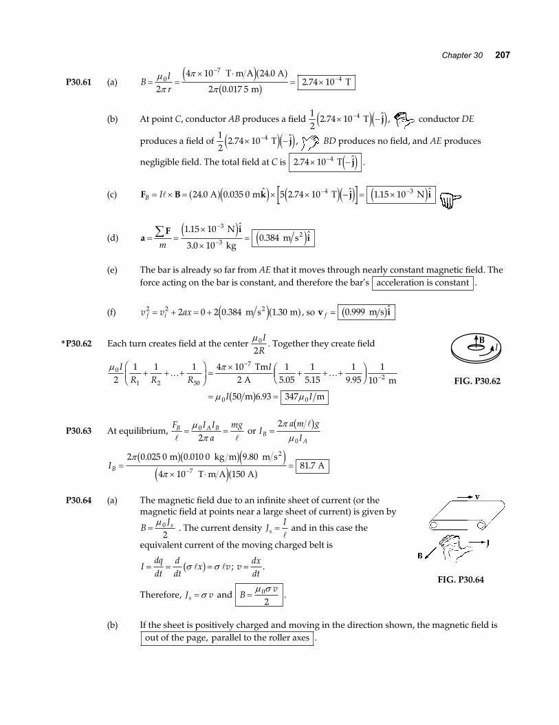
P30.64 (a) The magnetic field due to an infinite sheet of current (or themagnetic field at points near a large sheet of current) is given by
BJs=
µ 0
2 . The current density J
Is = and in this case the
equivalent current of the moving charged belt is
Idqdt
ddt
x v= = =σ σb g ; vdxdt
= .
Therefore, J vs = σ and Bv
=µ σ0
2.
FIG. P30.64
(b) If the sheet is positively charged and moving in the direction shown, the magnetic field isout of the page, parallel to the roller axes .

208 Sources of the Magnetic Field
P30.65 The central wire creates field B =µπ0 1
2IR
counterclockwise. The curved portions of the loop feels no
force since × =B 0 there. The straight portions both feel I × B forces to the right, amounting to
FB I LIR
I I LR
= =20 1 0 1 22
2µπ
µπ
to the right .
P30.66 IrB
= =× ×
×=
−
−
2 2 9 00 10 1 50 10
4 10675
0
3 8
7
πµ
π
π
. .e je j A
Flow of positive current is downward negative charge flows upwardor .
P30.67 By symmetry of the arrangement, the magnitude of the net magnetic fieldat point P is B B x= 8 0 where B0 is the contribution to the field due to
current in an edge length equal to L2
. In order to calculate B0 , we use the
Biot-Savart law and consider the plane of the square to be the yz-plane withpoint P on the x-axis. The contribution to the magnetic field at point P dueto a current element of length dz and located a distance z along the axis isgiven by Equation 30.3.
Br
00
24=
×zµπI d
r.
FIG. P30.67
From the figure we see that
r x L z= + +2 2 24e j and d dz dzL x
L x z× = =
+
+ +sinr θ
2 2
2 2 2
4
4
e je j
.
By symmetry all components of the field B at P cancel except the components along x(perpendicular to the plane of the square); and
B Bx0 0= cosφ where cosφ =+
L
L x
2
42 2e j.
Therefore, B00
20
2
4x
LI dzr
= zµπ
θ φsin cos and B B x= 8 0 .
Using the expressions given above for sin cosθ φ , and r, we find
BIL
x L x L=
+ +
µ
π
02
2 2 2 22 4 2e je j e j.
P30.68 (a) From Equation 30.9, the magnetic field produced by one loop at the center of the second
loop is given by BIRx
I R
x x= = =
µ µ π
πµ µπ
02
3
02
30
32 2 2
e j where the magnetic moment of either loop
is µ π= I R2e j . Therefore,
FdBdx x
R I
xI Rxx = = FHG
IKJFHGIKJ = =µ µ
µ µπ
µ π
ππ µ0
4
02 2
40
2 4
423 3
232
e j.
(b) FI Rxx = =
× ⋅ ×
×= ×
− −
−
−32
32
4 10 10 0 5 00 10
5 00 105 92 100
2 4
4
7 2 3 4
2 48π µ π π T m A A m
m N
e ja f e je j
. .
..

Chapter 30 209
P30.69 There is no contribution from the straight portion of thewire since ds r× = 0 . For the field of the spiral,
dI d
r
BI d
rI
drr
BI
r drI
r
Bs r
s r
=×
= = FHGIKJ
LNM
OQP
= = −
= =
−
=
−
=
z zz
µπ
µπ
θ µπ
π
µπ
µπ
θ
π
θ
π
θ
π
θ
θ
02
02
0
20
20
2
0 2
0
20 1
0
2
4
4 42
34
1
4 4
a fb g
e j
e j
sinsin
FIG. P30.69
Substitute r e= θ : BI
eI
e eI
e= − = − − = −− − −µπ
µπ
µπ
θ π π π00
2 0 2 0 0 2
4 4 41e j out of the page.
P30.70 (a) B B M= +0 0µ
MB B
=− 0
0µ and M =
−B B0
0µ
Assuming that B and B0 are parallel, this
becomes MB B
=− 0
0µ.
The magnetization curve gives a plot of Mversus B0 .
(b) The second graph is a plot of the relative
permeability BB0
FHGIKJ as a function of the applied
field B0 .
8 000
4 000
00.0 1.0 2.0 3.0
B/B0
B0 (mT)
Relative Permeability
FIG. P30.70

210 Sources of the Magnetic Field
P30.71 Consider the sphere as being built up of little rings of radius r,centered on the rotation axis. The contribution to the field fromeach ring is
dBr dI
x r=
+
µ02
2 2 3 22e j
where dIdQt
dQ= =
ωπ2
dQ dV rdr dx= =ρ ρ π2b ga f
dBr drdx
x r=
+
µ ρω03
2 2 3 22e j
where ρπ
=Q
R4 3 3b g
Br drdx
x rr
R x
x R
R
=+=
−
=−
+
zz µ ρω03
2 2 3 20 2
2 2
e j
������������������������������������������������������������������������������������������
������������������������������������������������������������r
x
dr
dx
ω
R
FIG. P30.71
Let v r x= +2 2 , dv rdr= 2 , and r v x2 2= −
Bv x dv
vdx v dv x v dv dx
B v x v dx R x xR x
dx
BxR
x R
v x
R
x R
R
v x
R
v x
R
x R
R
x
R
x
R
x R
R
x R
R
=−
= −LNMM
OQPP
= +LNM
OQP = − + −
FHG
IKJ
LNMM
OQPP
= − +LNM
==−
+− −
===−
−
=− =−
zz zzz
z z
µ ρω µ ρω
µ ρω µ ρω
µ ρω
02
3 20 1 2 2 3 2
0 1 2 2 1 2 0 2
02
2 2 4
42 2
42 2
1 1
42 4 2
2
2
2
2
2
2
2
2
2
2
e j
e j c hOQP
= − +LNM
OQP
= − +FHG
IKJ =
−z zdx
xR
x R dx
BRR
RR
R
R
R R24
2 4 2
24
23
42
23
02
0
03 2
2 02
µ ρω
µ ρω µ ρω
P30.72 Consider the sphere as being built up of little rings of radius r,centered on the rotation axis. The current associated with eachrotating ring of charge is
dIdQt
rdr dx= =ωπ
ρ π2
2b ga f .
The magnetic moment contributed by this ring is
d A dI r rdr dx r drdxµ πωπ
ρ π πωρ= = =a f b ga f2 3
22
������������������������������������������������������������������������������������������������������������������������r
x
dr
dx
ω
R
FIG. P30.72
µ πωρ πωρ πωρ
µ πωρ πωρ
µπωρ πωρ πωρ
=L
NMM
O
QPP =
−FH IK=
−
= − + = −FHGIKJ +
LNMM
OQPP
= − +FHG
IKJ =
FHGIKJ =
=
−
=−
+
=−
+
=−
+
=−
+
zz z z
z
r dr dxR x
dxR x
dx
R R x x dx R R RR R
RR R
r
R x
x R
R
x R
R
x R
R
x R
R
3
0
2 24
2 2 2
4 2 2 4 4 23 5
55 5
2 2
4 4
42
42 2
23
25
42
43
25 4
1615
415
e j
e j a f
up

Chapter 30 211
P30.73 Note that the current I exists in the conductor with a
current density JIA
= , where
A aa a a
= − −LNM
OQP
=ππ2
2 2 2
4 4 2.
Therefore, JIa
=2
2π.
To find the field at either point P1 or P2 , find Bs whichwould exist if the conductor were solid, using Ampère’slaw. Next, find B1 and B2 that would be due to the
conductors of radius a2
that could occupy the void where
the holes exist. Then use the superposition principle andsubtract the field that would be due to the part of theconductor where the holes exist from the field of thesolid conductor.
������������������������������������������������������������������������������������������������������������������������������������������������������������������������������������������������������������������������������������������������������������������������������������������������������������������������������������������������������������������������������������������������������������������������������������������������������������������������������������ θ θ
θ
Bs
-B1
-B2
P1
r
r
r 2 + a 2( )2
a/2
a/2
Bs
− ′ B 1 − ′ B 2
P2
FIG. P30.73
(a) At point P1 , BJ a
rs =µ π
π0
2
2e j
, BJ a
r a1
022
2 2=
−
µ π
π
b gb gd i , and B
J a
r a2
022
2 2=
+
µ π
π
b gb gd i .
B B B BJ a
r r a r a
BI r a r
r r a
Ir
r ar a
s= − − = −−
−+
LNMM
OQPP
=− −
−
L
NMMM
O
QPPP
=−−
LNM
OQP
1 2
2
02 2 2
2 20
2 2
2 2
21 1
4 21
4 2
22
4 2
4 4
24
µ ππ
µπ
µπ
b gd i b gd ia f
e je j directed to the left
(b) At point P2 , BJ a
rs =µ π
π0
2
2e j
and ′ = ′ =+
B BJ a
r a1 2
02
2 2
2
2 2
µ π
π
b gb g
.
The horizontal components of ′B1 and ′B2 cancel while their vertical components add.
B B B BJ a
rJ a
r a
r
r a
BJ a
rr
r a
Ir
rr a
Ir
r ar a
s= − ′ − ′ = −+
F
HGGG
I
KJJJ +
= −+
L
NMMM
O
QPPP
= −+
LNM
OQP
=++
LNM
OQP
2
1 20
20
2
2 2 2 2
02 2
2 20
2 2
02 2
2 2
22
4
2 4 4
21
2 4
22
12
4
24
cos cosθ θµ π
πµ π
π
µ π
πµ
π
µπ
e je j e j
e je je j
a f
directed toward the top of the page
ANSWERS TO EVEN PROBLEMS
P30.2 20 0. Tµ P30.8 see the solution
P30.4 200 nTP30.10
1 14 2
0
πµ
+FHGIKJ
Ir
into the page
P30.6 11
20+FHGIKJπ
µ IR
into the page

212 Sources of the Magnetic Field
P30.12µ0
121 1Ia b
−FHGIKJ out of the page
P30.44 2 02.
P30.46 (a) 12 6. Tµ ; (b) 56 0. Tµ
P30.14µ
π
02 2 2 2
2 22
I a d d a d
ad a d
+ − +FH IK+
into the page P30.48 2 01. GA west
P30.50 ~10 5− T , enough to affect the compassnoticeablyP30.16 (a) 10 0. Tµ ; (b) 80 0. Nµ toward wire 1;
(c) 16 0. Tµ ; (d) 80 0. Nµ toward wire 2P30.52 12 0. mN −ke j
P30.18 Parallel to the wires and0 167. m below the upper wire
P30.54µ ω
π0
2 5 5
q
R.P30.20 (a) opposite; (b) 67 8. A
P30.56 1 80. mTP30.22 5.40 cm
P30.58 (a) µ σ0 v horizontally away from you;P30.24 (a) 400 cm; (b) 7 50. nT ; (c) 1 26. m; (d) zero
(b) 0; (c) 12 0
2 2µ σ v up; (d) 3 00 108. × m sP30.26 (a) 3 60. T ; (b) 1 94. T
P30.60 (a) see the solution; (b) 3 20 10 13. × − T;P30.28 500 A
(c) 1 02 10 24. × − N away from the firstproton;P30.30 (a) see the solution; (b) d a=(d) 2 30 10 22. × − N away from the firstproton
P30.32 (a) µ0
2 2 2 22IN a
a R
a
a R+−
−
− +
L
NMMM
O
QPPPa f
;P30.62 347 0µ I m perpendicular to the coil
(b) see the solutionP30.64 (a)
12 0µ σ v ; (b) out of the page,
parallel to the roller axesP30.34 (a) −B Rπ θ2 cos ; (b) B Rπ θ2 cos
P30.36 (a) 7 40. Wbµ ; (b) 2 27. Wbµ P30.66 675 A downward
P30.38 (a) 7 19 1011. × ⋅ V m s ; (b) 200 nT P30.68 (a) see the solution; (b) 59 2. nN
P30.70 see the solutionP30.40 277 mA
P30.724
155πωρR upwardP30.42 2 97 104. ×
⋅⋅
K J
T m2 3