Embed Size (px)
Citation preview
SOURCE TEST PROCEDURES
MANUAL
SANTA BARBARA COUNTY AIR POLLUTION CONTROL DISTRICT 26 Castilian, Suite B-23 Goleta, California 93117 (805) 961-8800
Revised May, 1990
Doc# RCD.0010
1 Qtr 1990
Rev# 2
Page i of vi
TABLE OF CONTENTS SECTION NUMBER AND TITLE PAGE ABBREVIATIONS AND ACRONYMS iv 1.0 INTRODUCTION 1.1
2.0 SELECTION OF A SOURCE TEST CONTRACTOR 2.1 3.0 SOURCE TEST PLANNING 3.1 3.1 Process Description 3.1 3.2 Sampling Site Location 3.1 3.3 Sample Matrix 3.2 3.4 Source Test Plan 3.3 Table 3.4 Source Test Plan: Example 3.4
Table of Contents Table 3.4.6.1 Minimum Source Test Report 3.11 Format Requirements 4.0 SOURCE TEST PROCEDURES 4.1 4.1 Sampling Point Determination 4.1 4.2 Determination of Stack Gas Velocity and 4.1
Volumetric Flow Rate Table 4.1 List of Test Methods 4.2
4.3 Gas Analysis for CO2, O2 and Dry Molecular 4.3 Weight 4.4 Determination of Moisture Content 4.4 4.5 Determination of Particulate Emissions 4.5 4.6 Determination of Sulfur Dioxide Emissions 4.6
Doc# RCD.0010
1 Qtr 1990
Rev# 2
Page ii of vi
TABLE OF CONTENTS (continued) SECTION NUMBER AND TITLE PAGE 4.7 Determination of Oxides of Nitrogen 4.7
Emissions 4.8 Determination of Sulfuric Acid Mist and 4.9 SO2 Emissions
4.9 Determination of Sulfur Dioxide Emissions 4.10 by Instrument 4.10 Determination of Carbon Monoxide Emissions 4.10 by Instrument 4.11 Determination of Hydrogen Sulfide Emissions 4.11 4.12 Determination of Total Reduced Sulfur 4.11 Emissions 4.13 Determination of Hydrocarbon Emissions 4.12 4.14 Determination of O2 and CO2 Emissions 4.14
by Instrument 4.15 Other Source Test Requirements 4.14 4.16 Test Invalidation Criteria 4.15 5.0 CALCULATIONS 5.1 5.1 Stack Gas Velocity and Volumetric Flow Rate 5.1 5.2 Stack Gas Molecular Weight 5.1 5.3 Stack Gas Moisture Content and Dry Gas 5.2 Volume
5.4 Particulate Emissions 5.2 5.5 Sulfuric Acid Mist and SO2 Emissions 5.4 5.6 H2S Emissions 5.4 5.7 Instrument Methods 5.5
Doc# RCD.0010
1 Qtr 1990
Rev# 2
Page iii of vi
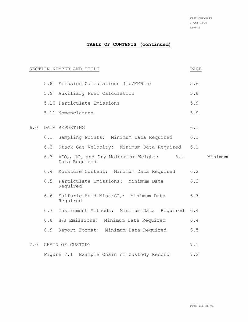
TABLE OF CONTENTS (continued) SECTION NUMBER AND TITLE PAGE 5.8 Emission Calculations (lb/MMBtu) 5.6 5.9 Auxiliary Fuel Calculation 5.8 5.10 Particulate Emissions 5.9
5.11 Nomenclature 5.9 6.0 DATA REPORTING 6.1 6.1 Sampling Points: Minimum Data Required 6.1 6.2 Stack Gas Velocity: Minimum Data Required 6.1 6.3 %CO2, %O2 and Dry Molecular Weight: 6.2 Minimum
Data Required 6.4 Moisture Content: Minimum Data Required 6.2
6.5 Particulate Emissions: Minimum Data 6.3
Required 6.6 Sulfuric Acid Mist/SO2: Minimum Data 6.3
Required 6.7 Instrument Methods: Minimum Data Required 6.4 6.8 H2S Emissions: Minimum Data Required 6.4 6.9 Report Format: Minimum Data Required 6.5 7.0 CHAIN OF CUSTODY 7.1
Figure 7.1 Example Chain of Custody Record 7.2
Doc# RCD.0010
1 Qtr 1990
Rev# 2
Page iv of vi
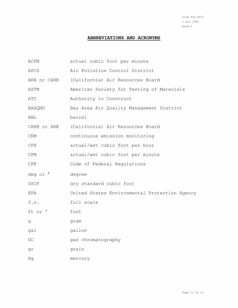
ABBREVIATIONS AND ACRONYMS ACFM actual cubic foot per minute APCD Air Pollution Control District ARB or CARB (California) Air Resources Board ASTM American Society for Testing of Materials ATC Authority to Construct
BAAQMD Bay Area Air Quality Management District BBL barrel CARB or ARB (California) Air Resources Board CEM continuous emission monitoring CFH actual/wet cubic foot per hour CFM actual/wet cubic foot per minute CFR Code of Federal Regulations
deg or degree DSCF dry standard cubic foot EPA United States Environmental Protection Agency f.s. full scale ft or ' foot g gram gal gallon
GC gas chromatography gr grain Hg mercury
Doc# RCD.0010
1 Qtr 1990
Rev# 2
Page v of vi
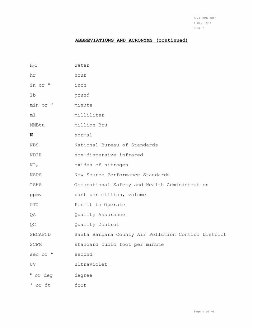
ABBREVIATIONS AND ACRONYMS (continued) H2O water hr hour in or " inch lb pound min or ' minute
ml milliliter MMBtu million Btu N normal
NBS National Bureau of Standards NDIR non-dispersive infrared NOx oxides of nitrogen NSPS New Source Performance Standards
OSHA Occupational Safety and Health Administration ppmv part per million, volume PTO Permit to Operate QA Quality Assurance QC Quality Control SBCAPCD Santa Barbara County Air Pollution Control District SCFM standard cubic foot per minute
sec or " second UV ultraviolet
or deg degree ' or ft foot
Doc# RCD.0010
1 Qtr 1990
Rev# 2
Page vi of vi
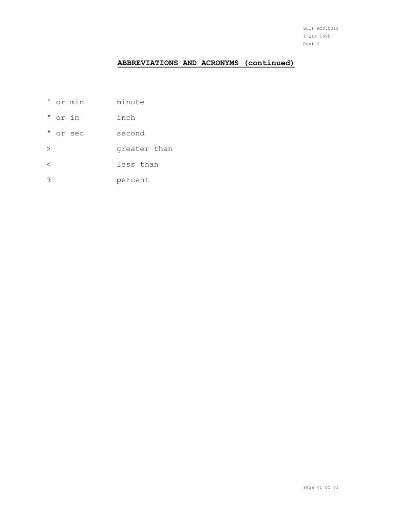
ABBREVIATIONS AND ACRONYMS (continued) ' or min minute " or in inch " or sec second > greater than < less than
% percent
Doc# RCD.0010
1 Qtr 1990
Rev# 2
Page 1.1
SECTION 1. INTRODUCTION Emissions testing is required by the Santa Barbara County Air Pollution Control District (SBCAPCD), hereafter "the District", to determine the types and amounts of pollutants emitted by various emission sources. Information gathered from source tests is used for planning, issuing permits, evaluating control systems, updating emissions inventories and enforcing emissions limitations. For these purposes, source tests must yield data in which the District has confidence. Confidence in the data is achieved by establishing test procedures and quality assurance programs that strive to
produce consistent test data that are complete, representative, precise, accurate and traceable. Various Federal, State and local agencies have developed source test procedures and quality assurance programs. This manual identifies those methods and procedures which satisfy the District's requirements for complete, representative, precise, accurate and traceable data gathering for source testing. The purpose of this manual is to standardize the test procedures to be used for each test program. Additional requirements for accepted test methods are included to increase the quality of the data. The manual also provides the tester with criteria by which the testing will be judged.
The test methods and requirements contained herein are current as of the date of issuance. However, the District reserves the right to stipulate more stringent test requirements or modify the procedures to suit individual sources or testing objectives to obtain quality data.
Doc# RCD.0010
1 Qtr 1990
Rev# 2
Page 2.1
SECTION 2. SELECTION OF A SOURCE TEST CONTRACTOR The majority of test programs are performed by independent source test consultants contracted by the source operator. The District may elect to contract the source test and be reimbursed by the source operator under special circumstances, including non-performance by the permit holder. When selecting a contractor, the type of test, type of process and any special sampling conditions should be considered. Select a contractor who has experience in the same or similar type of process
and test requirements. The prospective contractor must be certified by the California Air Resources Board (CARB) for the type of testing to be performed. Call the Regulatory Compliance Division of SBCAPCD for a list of contractors that have been used in the past within the District and the certifications for these contractors. The District is prohibited from recommending particular contractors. In order to ensure that contractors are certified and qualified to perform the sampling and analyses required, thereby providing data of known quality and preventing potential conflict of interest issues, all contractors used for District required source tests must be approved by the District.
Doc# RCD.0010
1 Qtr 1990
Rev# 2
Page 3.1
SECTION 3. SOURCE TEST PLANNING Planning of a source test program, or even a single source test, is essential in ensuring complete, representative, precise, accurate and traceable data. Consistent with the permit conditions specified in the ATC/PTO, a "Source Test Plan" must be approved by the District prior to any test date. The minimum information required to be in a Source Test Plan is outlined in Section 3.4 of this manual. A Source Test Plan for every source test must be submitted to the District by the source operator, generally a minimum of 30 days (in some cases more) prior to the proposed test date, for
approval by the District. Applicants should review their specific permit condition requirements for required submittal dates. 3.1 Process Description A detailed description of the process is required, including a block process flow diagram. Important parameters to include are: process type, process rates, control equipment and fuel type (if any). If the process is of a cyclic or batch type, the test program must be adjusted to ensure a representative sample. 3.2 Sampling Site Location In selecting a sampling site, every attempt should be made to obtain the most representative measurement of the source being tested. The ideal site would be eight (8) equivalent diameters downstream of a flow disturbance and two (2) equivalent diameters upstream of a flow disturbance. If an ideal sampling site which meets the above criteria is not available due to the placement of process equipment, general accessibility and interfering duct work, or for safety reasons, then a minimum requirement for a sampling site location of two (2) diameters downstream and one-half (0.5) diameters upstream of a flow disturbance must be met. If the above minimum requirements cannot be met, a sample site can be qualified for use by confirming the absence of cyclonic flow using the procedures in EPA Reference Method 1, section 2.4.
However, the District may require qualification of the site by the alternate procedures in EPA Reference Method 1, section 2.5, under special circumstances. 3.2.1 Sample Port Location
For a round stack, two ports must be located at ninety degrees (90 ) apart on the same plane which is perpendicular to the stack gas flow. For a rectangular stack, the cross-sectional area is divided
Doc# RCD.0010
1 Qtr 1990
Rev# 2
Page 3.2
into equal areas and the sampling ports must be located to enable measurement in the center of each area. Refer to EPA Method 1 for required number of traverse points and for additional details. The ports for both round and rectangular stacks must be located in such a way as to minimize any obstructions that would prevent the sample probe (of at least the same length as the stack diameter) from being inserted in the stack. Examples are platform railings, adjacent equipment and other objects. Unless the platform railing can be (in part) removed, the minimum vertical clearance above the railing should be fourteen inches (14"). 3.2.2 Sample Port Specifications
The sample port must be Schedule 40 NPT pipe, at least three inches (3") in diameter, welded approximately flush to the inside of the stack wall and protruding about three inches (3") from the outer wall of the stack or duct. The threads may be external or internal, but a cap or plug is necessary to close the port. Most probe support assemblies require an eye-bolt which is either welded or bolted three feet (3') to six feet (6') above the port. The eye-bolt must be capable of withstanding a working load of at least one-hundred (100) pounds. If the static pressure within the stack is above ten inches (+10") H2O, or if hazardous gases are present, a minimum four-inch (4") gate valve and packing gland should be attached to the port to fit the sample probe. This may also be desirable if the process is very sensitive to pressure changes.
3.2.3 Platform Specifications The working platform for source testing should be at least three feet (3') wide and capable of supporting at least two (2) people plus one hundred pounds (100 lb) of equipment. It should also conform to all pertinent OSHA regulations. Electrical power (115 V, 30 A) should be available within one hundred feet (100') of the platform. If more than one sample train will be used at the same time, two separate electrical circuits will be needed. 3.3 Sample Matrix The parameters of the gas stream to be sampled should be assessed. Parameters such as temperature, flow rate, static pressure,
particulate grain-loading, moisture content and potentially hazardous gases such as CO and H2S will affect both the safety and sampling strategies of the source test. The selection of proper equipment and test methods to suit the sample matrix is critical to the success and safety of the test program.
Doc# RCD.0010
1 Qtr 1990
Rev# 2
Page 3.3
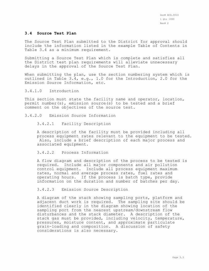
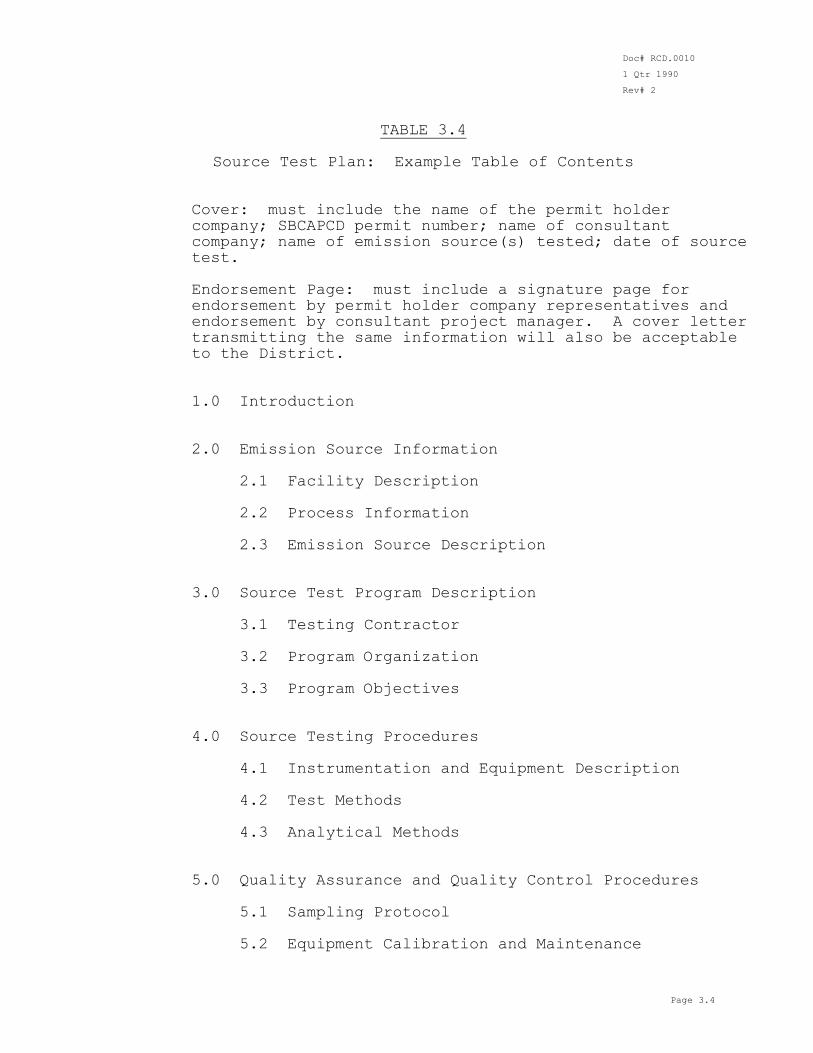
3.4 Source Test Plan The Source Test Plan submitted to the District for approval should include the information listed in the example Table of Contents in Table 3.4 as a minimum requirement. Submitting a Source Test Plan which is complete and satisfies all the District test plan requirements will alleviate unnecessary delays in the approval of the Source Test Plan. When submitting the plan, use the section numbering system which is outlined in Table 3.4, e.g., 1.0 for the Introduction, 2.0 for the Emission Source Information, etc.
3.4.1.0 Introduction This section must state the facility name and operator, location, permit number(s), emission source(s) to be tested and a brief comment on the objectives of the source test. 3.4.2.0 Emission Source Information 3.4.2.1 Facility Description A description of the facility must be provided including all
process equipment rates relevant to the equipment to be tested. Also, include a brief description of each major process and associated equipment.
3.4.2.2 Process Information A flow diagram and description of the process to be tested is
required. Include all major components and air pollution control equipment. Include all process equipment maximum rates, normal and average process rates, fuel rates and operating hours. If the process is batch type, provide information on the duration and number of batches per day.
3.4.2.3 Emission Source Description A diagram of the stack showing sampling ports, platform and
adjacent duct work is required. The sampling site should be identified clearly in the diagram showing location of the
sampling port from the nearest upstream/downstream flow disturbances and the stack diameter. A description of the stack gas must be provided, including velocity, temperature, pressures, moisture content, and approximate particulate grain-loading and composition. A discussion of safety considerations is also necessary.
Doc# RCD.0010
1 Qtr 1990
Rev# 2
Page 3.4
TABLE 3.4 Source Test Plan: Example Table of Contents Cover: must include the name of the permit holder
company; SBCAPCD permit number; name of consultant company; name of emission source(s) tested; date of source test.
Endorsement Page: must include a signature page for
endorsement by permit holder company representatives and endorsement by consultant project manager. A cover letter transmitting the same information will also be acceptable
to the District. 1.0 Introduction 2.0 Emission Source Information 2.1 Facility Description 2.2 Process Information 2.3 Emission Source Description
3.0 Source Test Program Description 3.1 Testing Contractor 3.2 Program Organization 3.3 Program Objectives 4.0 Source Testing Procedures 4.1 Instrumentation and Equipment Description 4.2 Test Methods
4.3 Analytical Methods 5.0 Quality Assurance and Quality Control Procedures 5.1 Sampling Protocol 5.2 Equipment Calibration and Maintenance
Doc# RCD.0010
1 Qtr 1990
Rev# 2
Page 3.5
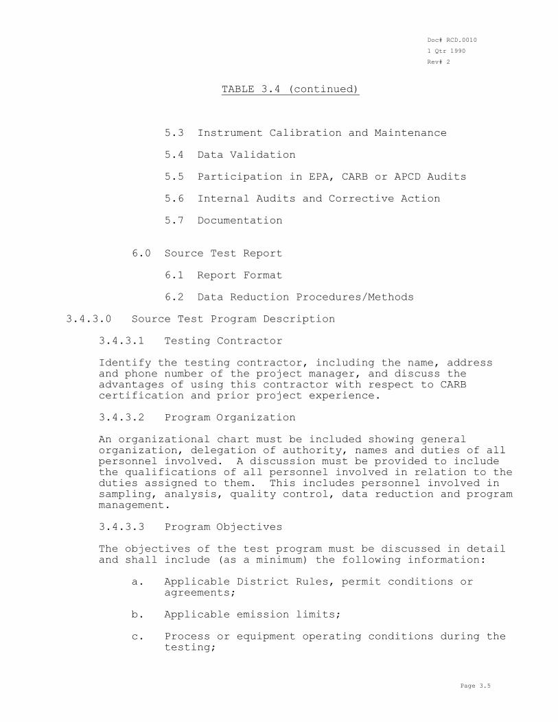
TABLE 3.4 (continued) 5.3 Instrument Calibration and Maintenance 5.4 Data Validation 5.5 Participation in EPA, CARB or APCD Audits 5.6 Internal Audits and Corrective Action 5.7 Documentation
6.0 Source Test Report 6.1 Report Format 6.2 Data Reduction Procedures/Methods 3.4.3.0 Source Test Program Description 3.4.3.1 Testing Contractor Identify the testing contractor, including the name, address
and phone number of the project manager, and discuss the advantages of using this contractor with respect to CARB
certification and prior project experience. 3.4.3.2 Program Organization An organizational chart must be included showing general
organization, delegation of authority, names and duties of all personnel involved. A discussion must be provided to include the qualifications of all personnel involved in relation to the duties assigned to them. This includes personnel involved in sampling, analysis, quality control, data reduction and program management.
3.4.3.3 Program Objectives The objectives of the test program must be discussed in detail
and shall include (as a minimum) the following information: a. Applicable District Rules, permit conditions or
agreements; b. Applicable emission limits; c. Process or equipment operating conditions during the
testing;
Doc# RCD.0010
1 Qtr 1990
Rev# 2
Page 3.6
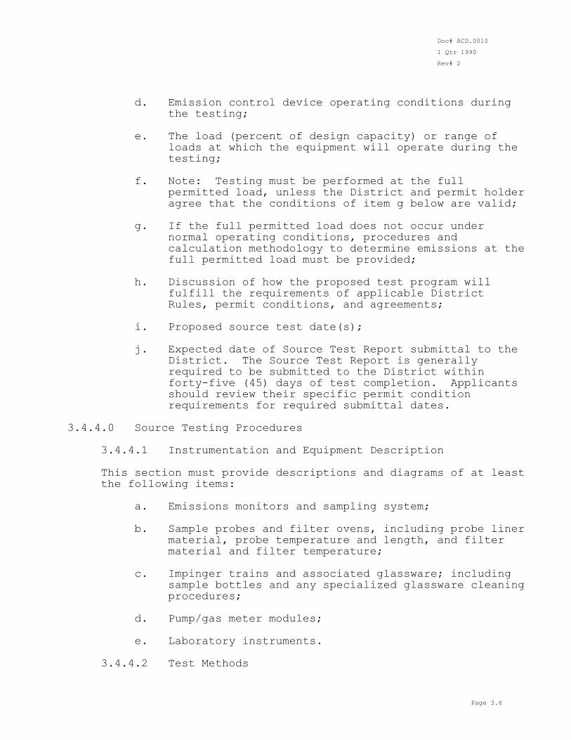
d. Emission control device operating conditions during
the testing; e. The load (percent of design capacity) or range of
loads at which the equipment will operate during the testing;
f. Note: Testing must be performed at the full
permitted load, unless the District and permit holder agree that the conditions of item g below are valid;
g. If the full permitted load does not occur under
normal operating conditions, procedures and
calculation methodology to determine emissions at the full permitted load must be provided;
h. Discussion of how the proposed test program will
fulfill the requirements of applicable District Rules, permit conditions, and agreements;
i. Proposed source test date(s); j. Expected date of Source Test Report submittal to the
District. The Source Test Report is generally required to be submitted to the District within forty-five (45) days of test completion. Applicants should review their specific permit condition
requirements for required submittal dates. 3.4.4.0 Source Testing Procedures 3.4.4.1 Instrumentation and Equipment Description This section must provide descriptions and diagrams of at least
the following items: a. Emissions monitors and sampling system; b. Sample probes and filter ovens, including probe liner
material, probe temperature and length, and filter material and filter temperature;
c. Impinger trains and associated glassware; including sample bottles and any specialized glassware cleaning procedures;
d. Pump/gas meter modules; e. Laboratory instruments. 3.4.4.2 Test Methods
Doc# RCD.0010
1 Qtr 1990
Rev# 2
Page 3.7
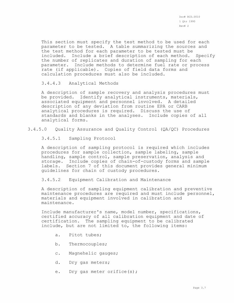
This section must specify the test method to be used for each
parameter to be tested. A table summarizing the sources and the test method for each parameter to be tested must be included. Include a brief description of each method. Specify the number of replicates and duration of sampling for each parameter. Include methods to determine fuel rate or process rate (if applicable). Copies of field data forms and calculation procedures must also be included.
3.4.4.3 Analytical Methods A description of sample recovery and analysis procedures must
be provided. Identify analytical instruments, materials,
associated equipment and personnel involved. A detailed description of any deviation from routine EPA or CARB analytical procedures is required. Discuss the use of standards and blanks in the analyses. Include copies of all analytical forms.
3.4.5.0 Quality Assurance and Quality Control (QA/QC) Procedures 3.4.5.1 Sampling Protocol A description of sampling protocol is required which includes
procedures for sample collection, sample labeling, sample handling, sample control, sample preservation, analysis and storage. Include copies of chain-of-custody forms and sample
labels. Section 7 of this document provides general minimum guidelines for chain of custody procedures.
3.4.5.2 Equipment Calibration and Maintenance A description of sampling equipment calibration and preventive
maintenance procedures are required and must include personnel, materials and equipment involved in calibration and maintenance.
Include manufacturer's name, model number, specifications,
certified accuracy of all calibration equipment and date of certification. The sampling equipment to be calibrated include, but are not limited to, the following items:
a. Pitot tubes; b. Thermocouples; c. Magnehelic gauges; d. Dry gas meters; e. Dry gas meter orifice(s);
Doc# RCD.0010
1 Qtr 1990
Rev# 2
Page 3.8
f. Barometer; g. Balances; h. Probe nozzles. Copies of standard forms for all calibration operations and
preventative maintenance must be included. A summary of equipment calibrations, including calibration factors and dates of calibration, and equipment maintenance schedules must be available to the District representative during the testing.
3.4.5.3 Instrument Calibration and Maintenance
This section must contain procedures for calibrating
instrumental emission monitors and any preventive maintenance performed on these instruments. Include a diagram of calibration gas flow through the sampling system. Specify calibration materials including supplier and guaranteed accuracy, stability of the calibration gas and National Bureau of Standards (NBS) traceability. Specify the percent of range at which the instruments will be calibrated. Include a brief description of multi-point and probe-tip calibrations. Copies of standard forms for all calibration operations and preventive maintenance must be included.
3.4.5.4 Data Validation
Data validation procedures must be outlined in this section and
should include the following: a. Data validation and editing philosophies; b. Type of personnel performing data validation; c. Sources of validation information used by data
editors; d. Specific validation procedures for each source test
method. 3.4.5.5 Participation in EPA, CARB, or APCD Audits
The testing contractor should provide information on their
participation in quality assurance audits. The audits should include analysis audits and sampling audits (concurrent testing with an agency test team). Include audit results in terms of accuracy and the date(s).
Doc# RCD.0010
1 Qtr 1990
Rev# 2
Page 3.9
3.4.5.6 Internal Audits and Corrective Action A description of internal audit and corrective action
procedures instituted by the test contractor to ensure quality of the data collected shall be included in this section of the report.
3.4.5.7 Documentation A description of the formal system used in document control and
record keeping as it applies to field data, e.g., generating, checking, inventory and archiving of supporting documentation, shall be included in this section of the report. Document control as it pertains to distribution and revision of the
Source Test Plan and Source Test Reports should also be covered in this section.
3.4.6.0 Source Test Report 3.4.6.1 Report Format A sample table of contents for a generalized Source Test Report
must be provided. Include a brief description of the contents of each section. Include as a minimum, the data in Table 3.4.6.1. Note that the final report submitted to the District after the completion of the source test must be signed by the source test project manager and by the person responsible for its review (quality assurance officer or supervisor).
3.4.6.2 Data Reduction Procedures/Methods Description of data reduction procedures should include example
calculations and formulas for each test method. The standard conditions used by the Santa Barbara County APCD are 29.92
inches of mercury (Hg") and 60 F.
Doc# RCD.0010
1 Qtr 1990
Rev# 2
Page 3.10
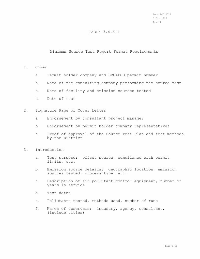
TABLE 3.4.6.1 Minimum Source Test Report Format Requirements 1. Cover a. Permit holder company and SBCAPCD permit number b. Name of the consulting company performing the source test
c. Name of facility and emission sources tested d. Date of test 2. Signature Page or Cover Letter a. Endorsement by consultant project manager b. Endorsement by permit holder company representatives c. Proof of approval of the Source Test Plan and test methods
by the District
3. Introduction a. Test purpose: offset source, compliance with permit
limits, etc. b. Emission source details: geographic location, emission
sources tested, process type, etc. c. Description of air pollutant control equipment, number of
years in service d. Test dates
e. Pollutants tested, methods used, number of runs f. Names of observers: industry, agency, consultant,
(include titles)
Doc# RCD.0010
1 Qtr 1990
Rev# 2
Page 3.11
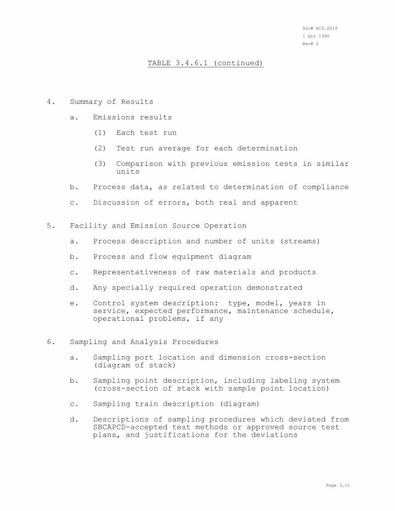
TABLE 3.4.6.1 (continued) 4. Summary of Results a. Emissions results (1) Each test run (2) Test run average for each determination (3) Comparison with previous emission tests in similar
units b. Process data, as related to determination of compliance c. Discussion of errors, both real and apparent 5. Facility and Emission Source Operation a. Process description and number of units (streams) b. Process and flow equipment diagram c. Representativeness of raw materials and products
d. Any specially required operation demonstrated e. Control system description: type, model, years in
service, expected performance, maintenance schedule, operational problems, if any
6. Sampling and Analysis Procedures a. Sampling port location and dimension cross-section
(diagram of stack) b. Sampling point description, including labeling system
(cross-section of stack with sample point location)
c. Sampling train description (diagram) d. Descriptions of sampling procedures which deviated from
SBCAPCD-accepted test methods or approved source test plans, and justifications for the deviations
Doc# RCD.0010
1 Qtr 1990
Rev# 2
Page 3.12
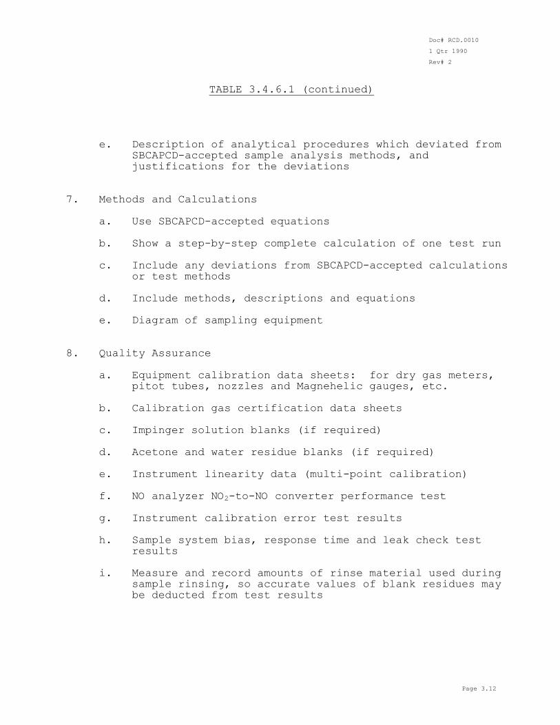
TABLE 3.4.6.1 (continued) e. Description of analytical procedures which deviated from
SBCAPCD-accepted sample analysis methods, and justifications for the deviations
7. Methods and Calculations a. Use SBCAPCD-accepted equations
b. Show a step-by-step complete calculation of one test run c. Include any deviations from SBCAPCD-accepted calculations
or test methods d. Include methods, descriptions and equations e. Diagram of sampling equipment 8. Quality Assurance a. Equipment calibration data sheets: for dry gas meters,
pitot tubes, nozzles and Magnehelic gauges, etc.
b. Calibration gas certification data sheets c. Impinger solution blanks (if required) d. Acetone and water residue blanks (if required) e. Instrument linearity data (multi-point calibration) f. NO analyzer NO2-to-NO converter performance test g. Instrument calibration error test results h. Sample system bias, response time and leak check test
results
i. Measure and record amounts of rinse material used during
sample rinsing, so accurate values of blank residues may be deducted from test results
Doc# RCD.0010
1 Qtr 1990
Rev# 2
Page 3.13
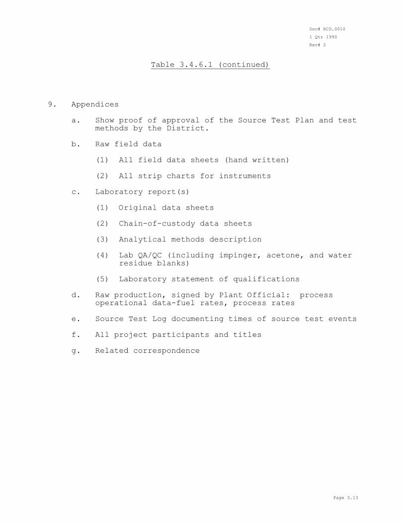
Table 3.4.6.1 (continued) 9. Appendices a. Show proof of approval of the Source Test Plan and test
methods by the District. b. Raw field data (1) All field data sheets (hand written)
(2) All strip charts for instruments c. Laboratory report(s) (1) Original data sheets (2) Chain-of-custody data sheets (3) Analytical methods description (4) Lab QA/QC (including impinger, acetone, and water
residue blanks) (5) Laboratory statement of qualifications
d. Raw production, signed by Plant Official: process
operational data-fuel rates, process rates e. Source Test Log documenting times of source test events f. All project participants and titles g. Related correspondence
Doc# RCD.0010
1 Qtr 1990
Rev# 2
Page 4.1
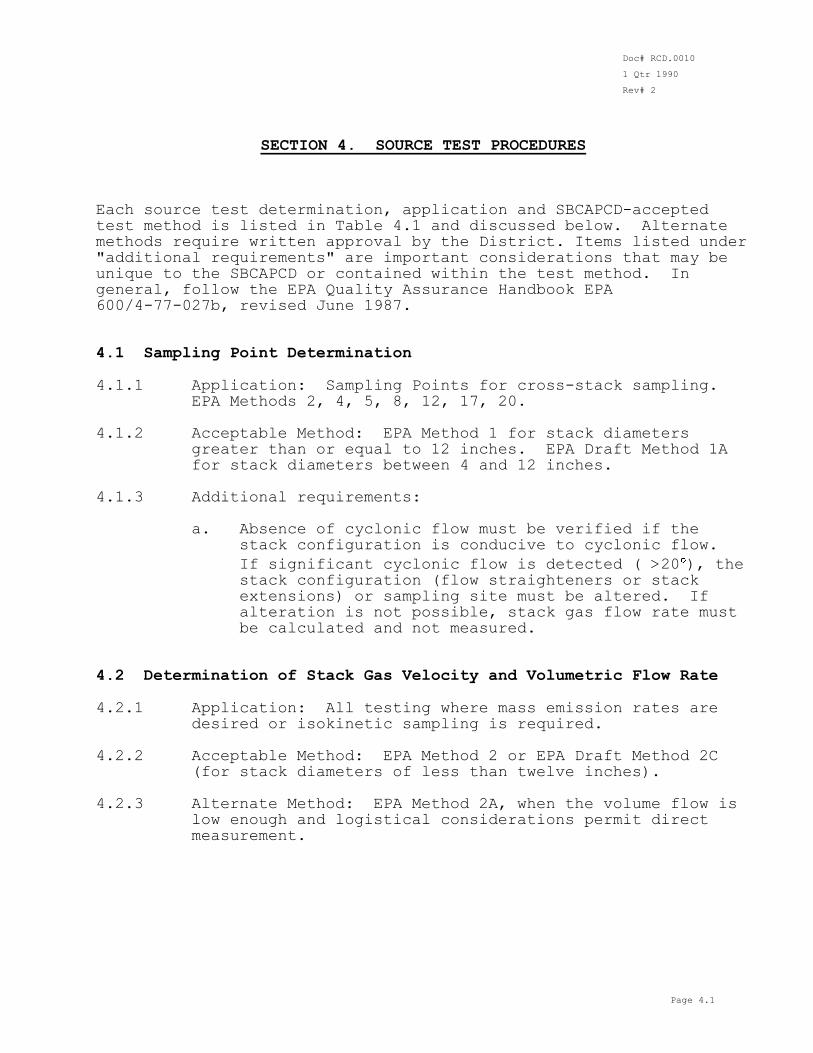
SECTION 4. SOURCE TEST PROCEDURES Each source test determination, application and SBCAPCD-accepted test method is listed in Table 4.1 and discussed below. Alternate methods require written approval by the District. Items listed under "additional requirements" are important considerations that may be unique to the SBCAPCD or contained within the test method. In general, follow the EPA Quality Assurance Handbook EPA 600/4-77-027b, revised June 1987. 4.1 Sampling Point Determination 4.1.1 Application: Sampling Points for cross-stack sampling.
EPA Methods 2, 4, 5, 8, 12, 17, 20. 4.1.2 Acceptable Method: EPA Method 1 for stack diameters
greater than or equal to 12 inches. EPA Draft Method 1A for stack diameters between 4 and 12 inches.
4.1.3 Additional requirements: a. Absence of cyclonic flow must be verified if the
stack configuration is conducive to cyclonic flow.
If significant cyclonic flow is detected ( >20 ), the
stack configuration (flow straighteners or stack extensions) or sampling site must be altered. If alteration is not possible, stack gas flow rate must be calculated and not measured.
4.2 Determination of Stack Gas Velocity and Volumetric Flow Rate 4.2.1 Application: All testing where mass emission rates are
desired or isokinetic sampling is required. 4.2.2 Acceptable Method: EPA Method 2 or EPA Draft Method 2C
(for stack diameters of less than twelve inches).
4.2.3 Alternate Method: EPA Method 2A, when the volume flow is low enough and logistical considerations permit direct measurement.
Doc# RCD.0010
1 Qtr 1990
Rev# 2
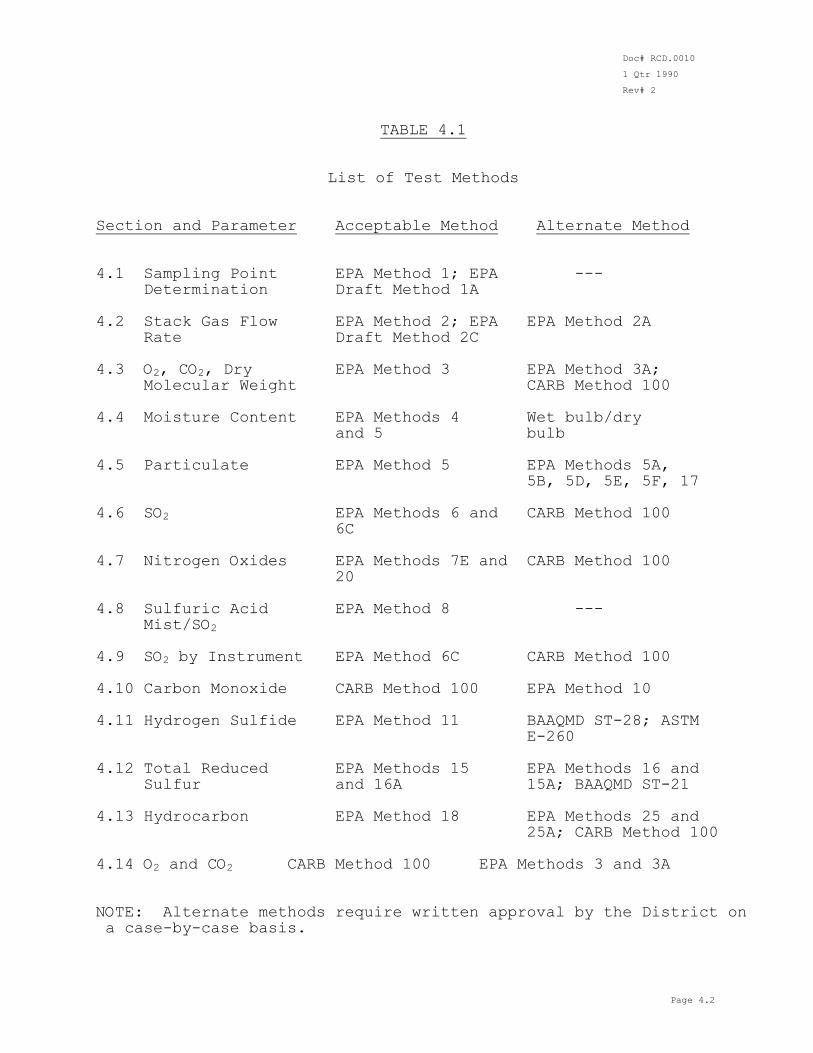
Page 4.2
TABLE 4.1 List of Test Methods Section and Parameter Acceptable Method Alternate Method 4.1 Sampling Point EPA Method 1; EPA --- Determination Draft Method 1A 4.2 Stack Gas Flow EPA Method 2; EPA EPA Method 2A Rate Draft Method 2C
4.3 O2, CO2, Dry EPA Method 3 EPA Method 3A; Molecular Weight CARB Method 100 4.4 Moisture Content EPA Methods 4 Wet bulb/dry and 5 bulb 4.5 Particulate EPA Method 5 EPA Methods 5A, 5B, 5D, 5E, 5F, 17 4.6 SO2 EPA Methods 6 and CARB Method 100 6C 4.7 Nitrogen Oxides EPA Methods 7E and CARB Method 100
20 4.8 Sulfuric Acid EPA Method 8 --- Mist/SO2 4.9 SO2 by Instrument EPA Method 6C CARB Method 100 4.10 Carbon Monoxide CARB Method 100 EPA Method 10 4.11 Hydrogen Sulfide EPA Method 11 BAAQMD ST-28; ASTM E-260 4.12 Total Reduced EPA Methods 15 EPA Methods 16 and Sulfur and 16A 15A; BAAQMD ST-21
4.13 Hydrocarbon EPA Method 18 EPA Methods 25 and 25A; CARB Method 100 4.14 O2 and CO2 CARB Method 100 EPA Methods 3 and 3A NOTE: Alternate methods require written approval by the District on a case-by-case basis.
Doc# RCD.0010
1 Qtr 1990
Rev# 2
Page 4.3
4.2.4 Additional Requirements: a. Pitot tubes must be constructed as per EPA Method 2,
section 2.1. Pitot tubes must be calibrated every sixty days (or when damaged) as per EPA Method 2, section 4.1.1 or section 4.1.2. Calibrated pitot tubes not meeting the criteria of EPA Method 2, section 4.1.4.5 may be used if the Cp used in the calculations is the impact side Cp of the calibration run with the delta P within 20% of the source delta P.
b. If a pressure-sensing instrument other than an
inclined manometer is used, it shall be calibrated as
per EPA Method 2, section 2.2 at intervals of every sixty days.
c. The pressure-sensing instrument should be chosen such
that the delta P reads at least 10% of full scale. d. Unacceptable sampling conditions: (1) If the stack gas flow is cyclonic or highly
irregular (wide velocity changes or pulsations) or the stack diameter is less than four inches, an alternate method must be used.
(2) If the average pressure differential (delta P)
of the sample points is less than 0.03 inches H2O, an alternate method must be used. An acceptable alternate method is fuel rate measurement, fuel analysis and calculation of a dry oxygen-based F factor as per Section 5.8.1. of this Manual. The F factor is multiplied by the heat input rate (MMBtu/min) and corrected for excess oxygen to calculate the flow rate.
e. For combustion sources with stacks less than four (4)
inches in diameter, the flow rate must be calculated from fuel use (heat input rate). The fuel metering system must be calibrated within 30 days of the test.
4.3 Gas Analysis for CO2, O2 and Dry Molecular Weight 4.3.1 Application: Calculation of excess air or dilution.
Determination of dry molecular weight for stack gas velocity calculations.
4.3.2 Acceptable Method: EPA Method 3. 4.3.3 Alternate Method: EPA Method 3A or CARB Method 100
Doc# RCD.0010
1 Qtr 1990
Rev# 2
Page 4.4
(Continuous Emissions Monitoring), when rapid changes in CO2 and O2 concentration may occur.
4.3.4 Additional Requirements: a. One integrated gas sample will be taken during each
pollutant emission rate determination run. b. The integrated gas sample will be taken at a constant
rate and simultaneous with, and for the same length of time as, the pollutant emission rate determination run.
c. Most acid gases are absorbed as CO2 in the Orsat
analyzer. If acid gases other than CO2 are known to be present in concentrations exceeding 0.2% by volume, they must be quantified.
4.4 Determination of Moisture Content 4.4.1 Application: Calculation of wet molecular weight.
Calculation of dry volumetric flow rate. Calculation of isokinetic sampling rate.
4.4.2 Acceptable Method: EPA Methods 4 or 5 (combined with
particulate measurement).
4.4.3 Alternate Method: If the stack gas is cool and dry, (less than 2% moisture by volume) then the moisture content may be calculated using wet bulb/dry bulb gas temperatures and a psychrometric table.
4.4.4 Additional Requirements: a. The approximation method as per EPA Method 4, section
3 shall be used only to estimate the moisture content of the stack gas prior to isokinetic sampling.
b. In saturated or droplet-laden gas streams, two
determinations of moisture content must be made, one calculated from the saturation temperature of the stack gas and another measured by impinger analysis.
The lower of these two values shall be considered correct.
c. Minimum 20 DSCF sample volume per test.
Doc# RCD.0010
1 Qtr 1990
Rev# 2
Page 4.5
4.5 Determination of Particulate Emissions 4.5.1 Application: Particulate emissions determination in gas
streams with less than 1.0 gr/DSCF of particulate matter. 4.5.2 Acceptable Methods: EPA Method 5. 4.5.3 Alternate Methods: EPA Method 17 for gas streams that
meet criteria in EPA Method 17, section 0. EPA Methods 5A, 5B, 5D, 5E, 5F, as applicable.
4.5.4 Additional Requirements: a. The entire train liquid catch, unless other analyses
are to be performed on the sample, shall be
evaporated at a temperature of 220 F ± 10 F at ambient pressure. The net weight of this "back-half" particulate fraction shall be added to the filter and wash fraction weights. If other methods are combined with the particulate determination, only a known major portion of the impinger catch will be evaporated rather than the entire impinger catch.
b. If the possibility of pseudoparticulate species
formation exists from reaction of gaseous compounds such as SO2 in the impingers, the source test plan must address this issue. The method by which such interference will be corrected must be agreed upon by
the permit holder and the SBCAPCD prior to testing.
c. For stack gas temperatures above 800 F, the probe liner must be constructed of borosilicate glass or
quartz. At stack gas temperatures above 1200 F, quartz liners are recommended.
d. The dry gas meter must be calibrated as per EPA
Method 5, section 5.3, at intervals of every sixty days (or when damaged).
e. Pre-test and post-test leak checks (leak rate and
vacuum) must be performed and recorded. The post-test leak check must be completed at the highest
observed sample vacuum. A post-test leak rate of greater than 0.02 CFM or 4% of the average sampling rate (whichever is less) shall invalidate the test. Leak corrections are not allowed.
f. An impinger solution blank analysis must be performed
on the distilled water source. The impinger solution must contain less than 0.001 percent residue by weight.
Doc# RCD.0010
1 Qtr 1990
Rev# 2
Page 4.6
g. The sampling times and volumes must meet the
requirements of the applicable subpart of the Federal New Source Performance Standards (NSPS), 40 CFR 60. If the source type is not addressed by the NSPS, the minimum sampling time is 60 minutes and the minimum volume is 31.8 DSCF.
h. Particulate sampling tests with percent isokinetic
outside 100 ± 10% range shall invalidate the test. 4.6 Determination of Sulfur Dioxide Emissions
4.6.1 Application: Sulfur dioxide emissions determination in ammonia-free gas streams.
4.6.2 Acceptable Methods: EPA Method 6, EPA Method 6C (also
refer to Section 4.9 of this Manual). 4.6.3 Alternate Methods: CARB Method 100. 4.6.4 Additional Requirements: a. If the expected SO2 concentration is above 2000 ppmv,
use 6% H2O2 in water for the absorbing solution. b. If the isopropanol impinger is to be analyzed for SO3
content, a probe filter is necessary to prevent interferences from particulate contaminants.
c. Record pre-test and post-test leak checks. Post-test
leak checks must be completed at the highest observed sample vacuum. For EPA Reference Method 6 or CARB Method 6, a post-test leak rate in excess of 2% of the average sampling rate shall invalidate the test. For EPA Reference Method 6C or CARB Method 100, a post-test leak rate higher than 0.2 CFH or 1% of the average sampling rate (whichever is less) shall invalidate the test.
d. The sample probe must be heated (250 F ± 25 F) to
prevent water condensation. If a sample line is used between the probe and impinger train, it must also be
heated (250 F ± 25 F). e. The post-sampling purge volume must be at least 20
percent of the sample volume. f. If midget impingers are used, three successful test
series, each consisting of two 30-minute minimum length runs (6 individual runs of Method 6, for a
Doc# RCD.0010
1 Qtr 1990
Rev# 2
Page 4.7
total of three hours sampling time) are required. Alternatively, if larger impingers (i.e., Method 5) are used, three successful test runs of one-hour each are required, similar to Method 8, as per section 2.1 of the method.
g. If ammonia or other interfering gases are present in
the gas stream, alternate methods must be used. The methods must be described in the source test plan and approved by the SBCAPCD prior to testing.
4.7 Determination of Oxides of Nitrogen Emissions
4.7.1 Application: Continuous NO/NOx emissions determination. 4.7.2. Acceptable Methods. EPA Method 7E, EPA Method 20 (Gas
Turbines). 4.7.3 Alternate Method: CARB Method 100. 4.7.4 Additional Requirements: a. A chemiluminescent analyzer is required.
b. NO2-to-NO converter must be catalytic (<400 C) if ammonia is expected to be present (unless an ammonia scrubber is used in the sampling system).
c. EPA Protocol I calibration gases are required. The
instrument range must be selected such that the sample concentration is at least 20 percent of range and not greater than the high calibration gas concentration. The high calibration gas concentration must be 60-90% of the instrument range. Calibration and sampling must be conducted using the same instrument range setting.
d. Ambient range analyzers utilizing dilution systems
are permissible if the analyzers are calibrated through the dilution system.
e. The sampling system must be constructed of teflon, glass or stainless steel such that at no time does sample gas pass through condensed water. Temperatures the sampling system is exposed to should be considered in choosing the material of construction. The portion of the sample line prior to water removal must be heated above the dew point of the sample gas.
Doc# RCD.0010
1 Qtr 1990
Rev# 2
Page 4.8
f. Section 6.4 of EPA Reference Method 7E and section 5.6 of EPA Reference Method 20 require on-site NO2-to-NO efficiency tests. The District prefers that the NO2-to-NO converter efficiency test be done in the field immediately prior to the source test. However, if the NO2-to-NO converter efficiency test is not performed in the field, the District requires the following:
1) The laboratory NO2-to-NO converter efficiency
test must be conducted as per section 5.6 of EPA Reference Method 20.
2) The laboratory NO2-to-NO converter efficiency
test must be done within 30 days prior to the source test.
3) The laboratory NO2-to-NO converter efficiency
test must be done using the NOx analyzer scale which will be used during the source test.
4) A copy of the strip chart recorder tracing from
the laboratory NO2-to-NO converter efficiency test and the NO2-to-NO converter identification number must be available for District inspection at the time of the source test.
5) If the District representative determines that
the NO2-to-NO converter failed the laboratory efficiency test, an on-site NO2-to-NO converter efficiency test must be performed and passed as per section 5.6 of EPA Reference Method 20 before source testing can continue.
g. Stacks with cross-sectional areas of greater than 50
square feet or the potential for concentration stratification require a traverse of the sample probe. Select the sample points as per EPA Method 20 or use EPA Method 1 to select a minimum of 8 points. Smaller stacks may be sampled at any point if concentration variation is less than 10% of the average concentration values obtained using the maximum number of sampling points. Sampling should
take place at the point of the lowest measured O2 concentration.
h. Three (3) 40-minute tests are required. If other
pollutants are being measured (i.e., particulate), the test runs must be approximately simultaneous with the other measurements. For example, if three particulate tests are to be performed, then three (40-minute) tests for NOx are required to be
Doc# RCD.0010
1 Qtr 1990
Rev# 2
Page 4.9
performed simultaneously. i. A strip chart recorder is required such that a
continuous trace of the pollutant concentration is obtained. The recorder must be adjusted to obtain a 5-10 percent zero offset. The maximum strip chart data reduction averaging interval is ten (10) minutes. The chart recorder must be readable to 0.5 percent of full scale. These requirements may be waived by the Santa Barbara County Air Pollution Control District if an automated data acquisition system is used.
j. If the zero or span drift of a test run exceeds ±3
percent of full scale, this invalidates the test run. k. A sampling system bias check must be performed at the
beginning and at the end of each test day (CARB Method 100). The sampling system bias check must be performed by injecting calibration gas at the probe tip at the same pressure (or vacuum) as the sample. If the bias check through the probe tip differs from the tag value of the gas by more than ±5%, all tests performed since the previous valid bias check become invalid. (Refer to EPA Method 6C, section 6.4.2.)
4.8 Determination of Sulfuric Acid Mist and Sulfur Dioxide
Emissions 4.8.1 Application: Determination of particulate sulfur (H2SO4
mist) and gaseous sulfur (SO2, SO3) emissions. Sulfates may also be quantified.
4.8.2 Acceptable Methods: EPA Method 8. 4.8.3 Alternate Method: Currently none. 4.8.4 Additional Requirements: a. EPA Method 8 may be combined with EPA Method 5.
b. Sample probe must be heated to 250 F ± 25 F. If a sample line is used between the probe and impingers,
it must be heated to 250 F ± 25 F. c. Sulfates may also be quantified if this method is
combined with Method 5. Total sulfate is the sum of the sulfates found in the probe wash and particulate filter and the H2SO4 found in the first impinger. The procedure for sulfate analysis in the probe wash and on the filter must be ion chromatography or titration
Doc# RCD.0010
1 Qtr 1990
Rev# 2
Page 4.10
as per EPA Method 8 with the addition of sample conditioning with an ion-exchange resin column or equivalent method to remove cation interference prior to titration.
d. Same requirements as per Sections 4.5.4.c and
4.5.4.d, of this Manual. e. Post-sampling purge volume must be at least 20
percent of the total sample volume. 4.9 Determination of Sulfur Dioxide Emissions by Instrument
4.9.1 Application: Continuous monitoring for SO2. 4.9.2 Acceptable Method: EPA Method 6C. 4.9.3 Alternate Method: CARB Method 100. 4.9.4 Additional Requirements: a. UV photometric absorption analyzer required. b. Same requirements as for NOx monitoring: Sections
4.7.4.c. through 4.7.4.k of this Manual (excluding converter performance test).
c. See comment on ammonia interference in Section 4.6.g of this Manual.
4.10 Determination of Carbon Monoxide Emissions by Instrument 4.10.1 Application: Continuous monitoring for CO. 4.10.2 Acceptable Method: CARB Method 100. 4.10.3 Alternate Method: EPA Method 10. 4.10.4 Additional Requirements: a. An NDIR analyzer or other acceptable infrared
detector is required. b. Same requirements as for NOx monitoring: Sections
4.7.4.c through 4.7.4.k of this Manual (excluding converter performance test).
c. The CO analyzer interference from CO2 must be
determined: If the analyzer used is subject to interference from CO2, the amount of interference
Doc# RCD.0010
1 Qtr 1990
Rev# 2
Page 4.11
(ppm CO/percent CO2) and the concentration of CO2 in the sample must be quantified and the final CO results corrected for interference. The interference must not exceed 1 ppm CO/percent CO2. If the analyzer is not subject to interference from CO2, an interference test must be included in the final test report.
4.11 Determination of Hydrogen Sulfide Emissions 4.11.1 Application: H2S concentration determination. 4.11.2 Acceptable Method: EPA Method 11.
4.11.3 Alternate Methods: BAAQMD ST-28, ASTM E-260 with thermal
conductivity detector (>1500 ppmv H2S). 4.11.4 Additional Requirements: a. If the H2S concentration in the sample gas is above
500 ppmv, a more concentrated solution of CdSO4 is recommended when using EPA Method 11 or BAAQMD ST-28. More concentrated reagents (0.1 N) are also recommended.
b. Pre-test and post-test leak checks must be performed
and recorded. The post-test leak test must be
completed at the highest observed sample vacuum. A post-test leak rate in excess of 4% of the average sampling rate or greater than 0.02 acfm (whichever is less) shall invalidate the test.
c. EPA Method 11: six tests of ten minute duration and
ten liters sample size each. BAAQMD ST-28: three tests of thirty minutes each. 4.12 Determination of Total Reduced Sulfur Emissions 4.12.1 Application: Determination of concentrations of reduced
sulfur compounds.
4.12.2 Acceptable Methods: EPA Method 15 (Sulfur Reducing
Processes), EPA Method 16A (Sulfur Oxidizing Processes). 4.12.3 Alternate Methods: EPA Method 15A, EPA Method 16, BAAQMD
ST-21. 4.12.4 Additional Requirements:
Doc# RCD.0010
1 Qtr 1990
Rev# 2
Page 4.12
a. A detailed description of the specific procedures to be used is to be reviewed and approved by the District. The minimum information required is: equipment list, methodology, quality assurance procedures, and a system diagram.
b. If the identification of specific reduced sulfur
compounds is necessary, EPA Method 16 is required (sulfur oxidizing processes).
4.13 Determination of Hydrocarbon Emissions 4.13.1 Application: Determination of Hydrocarbon Concentration.
4.13.2 Acceptable Method: EPA Method 18. 4.13.3 Alternate Methods: EPA Method 25, EPA Method 25A, CARB
Method 100, Gas Chromatography-Mass Spectrometer. 4.13.4 Specific requirements for low molecular weight alkane
measurement (C1 through C5+): a. The sampling procedure must follow EPA Method 18,
section 7.1.1 procedures. b. Calibration of the GC system must include the use of
at least one calibration gas concentration for each
carbon number. For example, a mixture of n-alkanes may be used to calibrate the GC system.
c. The calibration gas concentration must be similar to
the sample concentration (for each sample component) in that both the sample and calibration gas can be accurately quantified on the same attenuation setting.
d. The GC system must be calibrated prior to (initial)
and after (final) the analysis of each sample series, or at the beginning and end of the analysis day.
e. The initial and final calibrations must not differ by
more than five (5) percent.
f. The GC system must utilize a flame ionization
detector or mass spectrometer detector. g. The samples must be allowed to elute until the
n-pentane retention time has sufficiently passed to allow the sample to be back-flushed to produce a C5+ peak.
Doc# RCD.0010
1 Qtr 1990
Rev# 2
Page 4.13
h. The QC procedures for tedlar bags described in section 5.3.2 of EPA Reference Method 18 shall be followed.
4.14 Determination of Oxygen and Carbon Dioxide Emissions by
Instrument 4.14.1 Application: As per Section 4.3.1 of this Manual.
Continuous monitoring of O2 and CO2. 4.14.2 Acceptable Method: CARB Method 100. 4.14.3 Alternate Methods: EPA Method 3, 3A.
4.14.4 Additional Requirements: a. Same requirements as Sections 4.7.4.c to 4.7.4.k of
this Manual (excluding converter performance test). b. Calibration gases must be certified to ±2 percent
accuracy. 4.15 Other Source Test Requirements 4.15.1: All pollutant calibration gases should be prepared
according to EPA Protocol G-1. NBS diluent calibration gases must have a tolerance of <±2%. Any calibration gas
not prepared according to EPA Protocol G-1 will be subject to the following restrictions:
a. The cylinders are valid for up to six months after
the most recent certification date. b. The cylinder must be traceable to an NBS standard. c. The certified tag tolerance must be equal to or
better than ±2%. 4.15.2: All instruments used in instrument reference methods
except NOx analyzers must have passed a 3-point linearity check (section 5.3.1, EPA Reference Method 20) within 60 days prior to the source test. Actual response to the
high calibration gas must be within ±2% of the tagged value of the gas.
4.15.3: NOx analyzers require an on-site 3-point linearity check. 4.15.4: If a dilution system is warranted, it must use a
restricting orifice and have the proper linearity documentation (see Section 4.15.2 of this Manual). Dilution systems using rotometers are not acceptable.
Doc# RCD.0010
1 Qtr 1990
Rev# 2
Page 4.14
4.15.5: Both system pre-test and post-test leak checks are
required for all instrument methods. Any indicated leakage on a pre-test leak check must be corrected before testing can proceed. Any indicated leakage on a post-test leak check will invalidate all prior tests.
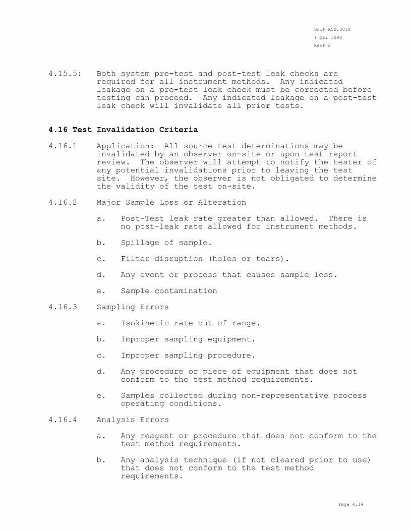
4.16 Test Invalidation Criteria 4.16.1 Application: All source test determinations may be
invalidated by an observer on-site or upon test report review. The observer will attempt to notify the tester of any potential invalidations prior to leaving the test
site. However, the observer is not obligated to determine the validity of the test on-site.
4.16.2 Major Sample Loss or Alteration a. Post-Test leak rate greater than allowed. There is
no post-leak rate allowed for instrument methods. b. Spillage of sample. c. Filter disruption (holes or tears). d. Any event or process that causes sample loss.
e. Sample contamination 4.16.3 Sampling Errors a. Isokinetic rate out of range. b. Improper sampling equipment. c. Improper sampling procedure. d. Any procedure or piece of equipment that does not
conform to the test method requirements. e. Samples collected during non-representative process
operating conditions.
4.16.4 Analysis Errors a. Any reagent or procedure that does not conform to the
test method requirements. b. Any analysis technique (if not cleared prior to use)
that does not conform to the test method requirements.
Doc# RCD.0010
1 Qtr 1990
Rev# 2
Page 4.15
NOTE: The above list represents a small fraction of the possible
errors that may invalidate a test. The District may decide to accept or reject the results based upon these and other criteria not presented here.
Doc# RCD.0010
1 Qtr 1990
Rev# 2
Page 5.1
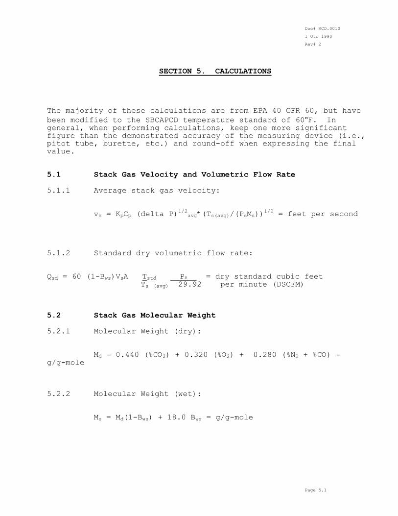
SECTION 5. CALCULATIONS The majority of these calculations are from EPA 40 CFR 60, but have
been modified to the SBCAPCD temperature standard of 60 F. In general, when performing calculations, keep one more significant figure than the demonstrated accuracy of the measuring device (i.e., pitot tube, burette, etc.) and round-off when expressing the final value.
5.1 Stack Gas Velocity and Volumetric Flow Rate 5.1.1 Average stack gas velocity: vs = KpCp (delta P)
1/2avg*(Ts(avg)/(PsMs))
1/2 = feet per second
5.1.2 Standard dry volumetric flow rate: Qsd = 60 (1-Bws)VsA Tstd Ps = dry standard cubic feet
Ts (avg) 29.92 per minute (DSCFM) 5.2 Stack Gas Molecular Weight 5.2.1 Molecular Weight (dry): Md = 0.440 (%CO2) + 0.320 (%O2) + 0.280 (%N2 + %CO) = g/g-mole
5.2.2 Molecular Weight (wet): Ms = Md(1-Bws) + 18.0 Bws = g/g-mole
Doc# RCD.0010
1 Qtr 1990
Rev# 2
Page 5.2
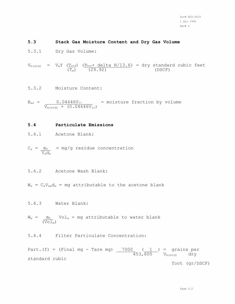
5.3 Stack Gas Moisture Content and Dry Gas Volume 5.3.1 Dry Gas Volume: Vm(std) = VmY (Tstd) (Pbar+ delta H/13.6) = dry standard cubic feet (Tm) (29.92) (DSCF) 5.3.2 Moisture Content:
Bws = 0.04646Vlc = moisture fraction by volume Vm(std) + (0.04646Vlc) 5.4 Particulate Emissions 5.4.1 Acetone Blank: Ca = ma = mg/g residue concentration Vada
5.4.2 Acetone Wash Blank: Wa = CaVawda = mg attributable to the acetone blank 5.4.3 Water Blank: Ww = mw Volw = mg attributable to water blank (Volb)
5.4.4 Filter Particulate Concentration: Part.(f) = (Final mg - Tare mg) 7000 ( 1 ) = grains per 453,600 Vm(std) dry standard cubic foot (gr/DSCF)
Doc# RCD.0010
1 Qtr 1990
Rev# 2
Page 5.3
5.4.5 Acetone Wash Particulate Concentration: Part.(w) = (Final mg - Tare mg - Wa) 7000 ( 1 ) = gr/DSCF 453,600 Vm(std) 5.4.6 Impinger Catch Particulate Concentration:
Part. (i) = (Final mg - Tare mg - Ww) 7000 ( 1 ) = gr/DSCF 453,600 Vm(std) 5.4.7 Total Particulate Concentration: Part.(total) = Part.(w) + Part.(f) + Part.(i) 5.4.8 Isokinetic Variation:
I = (100)Ts [K3Vlc + (Y Vm/Tm) (Pbar + H/13.6)] 60vsPsAnΘ Note: The above equation applies to all isokinetic
sampling: EPA Methods 5, 8, 12, 17, etc. 5.5 Sulfuric Acid Mist and Sulfur Dioxide Emissions 5.5.1 Sulfuric Acid Mist Concentration (including SO3):
N(Vt-Vtb) (Vsoln) C-H2SO4 = 1.081E-4 Val = pounds per dry standard Vm(std) cubic foot (lb/DSCF) N(Vt-Vtb) (Vsoln)
Doc# RCD.0010
1 Qtr 1990
Rev# 2
Page 5.4
C-H2SO4 = 418 Val = parts per million volume (ppmv) Vm(std) 5.5.2 Sulfur Dioxide Concentration: N(Vt-Vtb) (Vsoln) C - SO2 = 7.061E-5 Val = pounds per dry standard Vm(std) cubic foot
C - SO2 (parts per million) = see H2SO4 ppmv Note: Above calculations apply for EPA Methods 6 and 8. 5.6 Hydrogen Sulfide Emissions 5.6.1 H2S Concentration (EPA Method 11, ST-28): C-H2S = K [(VITNI-VTTNT)sample - (VITNI-VTTNT)blank] Vm(std)
C : parts per million volume: K = 418 5.7 Instrument Methods 5.7.1 Dilution Corrections: 3% O2 = 17.9 (measured concentration) (20.9 - measured %O2) 12% CO2 = ( 12.0 ) (measured concentration)
measured %CO2 5.7.2 Calibration Drift Corrections z = zero reading, % full scale s = span reading, % full scale
Doc# RCD.0010
1 Qtr 1990
Rev# 2
Page 5.5
i,f = subscripts denoting initial and final, respectively t = averaging time period - numbered l to n n = number of t's in the sampling period delta z = rate of change of zero reading, % full
scale/time interval delta s = rate of change of span reading, % full
scale/time interval
zt = corrected (apparent) zero reading for midpoint
of t, % full scale st = corrected (apparent) span reading for midpoint of t, % full scale Rt = average sample reading over time t, % full scale Cs = concentration of span gas, ppmv or % volume Ct = average corrected sample concentration for time
t, ppmv or % volume
Apparent zero: For each t from 1 to n delta z = (zf - zi)/n zt = z/2 + [delta z*(t-1)] + zi Apparent span: For each t from 1 to n delta s = (sf-si)/n st = s/2 + [delta s*(t-1)] + si Average corrected sample concentration: For each t from 1 to n
Ct = Rt-Zt Cs St-Zt Note: This method assumes the zero reading is at or
reset to Zi prior to reading Sf.
Doc# RCD.0010
1 Qtr 1990
Rev# 2
Page 5.6
5.8 Emission Calculations (pounds per million Btu) 5.8.1 Nomenclature: %C = percent carbon in the fuel, by weight %H = percent hydrogen in the fuel, by weight %O = percent oxygen in the fuel, by weight %N = percent nitrogen in the fuel, by weight %S = percent sulfur in the fuel, by weight
GC = higher heating value, dry basis, Btu/lb
Fd = Dry, oxygen-based F factor, DSCF/MMBtu at 60F FR = Fuel rate, CFM or gal/min., etc. MW = Molecular weight of pollutant, g/g-mole 5.8.2 Calculations: Fd = 520 (10
6)(3.64(%H) + 1.53(%C) + 0.57(%S) + 0.14(%N) -
0.46(%0)) (528) GCV
a. Solid Pollutants: lbs/MMBtu = ( gr ) ( lb ) Fd ( 20.9 ) SDCF 7000 gr 20.9 - measured %O2 b. Gaseous Pollutants: lbs/MMBtu = (K)ppmv(MW)Fd 20.9
(20.9 - measured %O2) K = 2.635E-9
Doc# RCD.0010
1 Qtr 1990
Rev# 2
Page 5.7
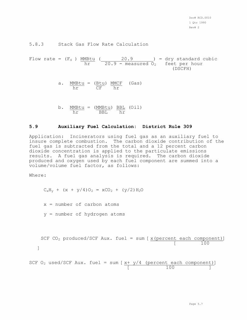
5.8.3 Stack Gas Flow Rate Calculation Flow rate = (Fd ) MMBtu ( 20.9 ) = dry standard cubic hr 20.9 - measured O2 feet per hour (DSCFH) a. MMBtu = (Btu) MMCF (Gas) hr CF hr
b. MMBtu = (MMBtu) BBL (Oil) hr BBL hr 5.9 Auxiliary Fuel Calculation: District Rule 309 Application: Incinerators using fuel gas as an auxiliary fuel to insure complete combustion. The carbon dioxide contribution of the fuel gas is subtracted from the total and a 12 percent carbon dioxide concentration is applied to the particulate emissions results. A fuel gas analysis is required. The carbon dioxide produced and oxygen used by each fuel component are summed into a volume/volume fuel factor, as follows:
Where: CxHy + (x + y/4)O2 = xCO2 + (y/2)H2O x = number of carbon atoms y = number of hydrogen atoms SCF CO2 produced/SCF Aux. fuel = sum [x(percent each component)] [ 100
] SCF O2 used/SCF Aux. fuel = sum [x+ y/4 (percent each component)] [ 100 ]
Doc# RCD.0010
1 Qtr 1990
Rev# 2
Page 5.8
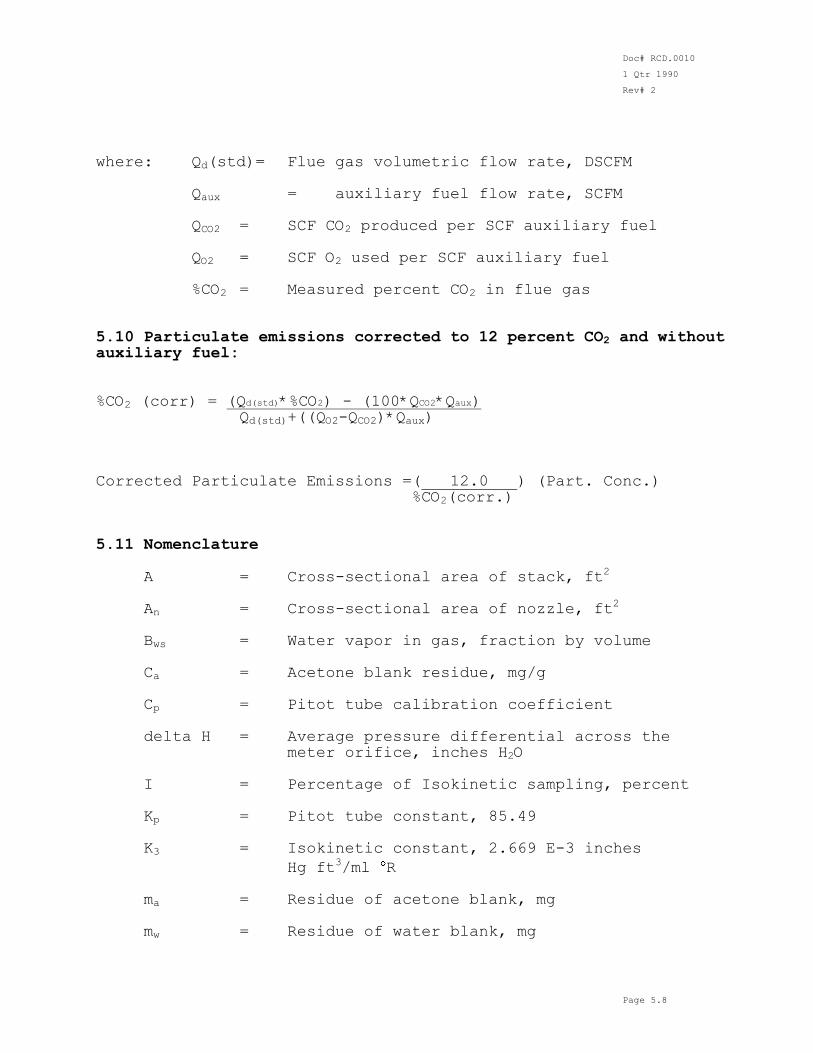
where: Qd(std)= Flue gas volumetric flow rate, DSCFM Qaux = auxiliary fuel flow rate, SCFM QCO2 = SCF CO2 produced per SCF auxiliary fuel QO2 = SCF O2 used per SCF auxiliary fuel %CO2 = Measured percent CO2 in flue gas 5.10 Particulate emissions corrected to 12 percent CO2 and without auxiliary fuel: %CO2 (corr) = (Qd(std)*%CO2) - (100*QCO2*Qaux) Qd(std)+((QO2-QCO2)*Qaux) Corrected Particulate Emissions =( 12.0 ) (Part. Conc.) %CO2(corr.) 5.11 Nomenclature
A = Cross-sectional area of stack, ft2
An = Cross-sectional area of nozzle, ft
2
Bws = Water vapor in gas, fraction by volume Ca = Acetone blank residue, mg/g Cp = Pitot tube calibration coefficient delta H = Average pressure differential across the meter orifice, inches H2O I = Percentage of Isokinetic sampling, percent
Kp = Pitot tube constant, 85.49 K3 = Isokinetic constant, 2.669 E-3 inches
Hg ft3/ml R
ma = Residue of acetone blank, mg mw = Residue of water blank, mg
Doc# RCD.0010
1 Qtr 1990
Rev# 2
Page 5.9
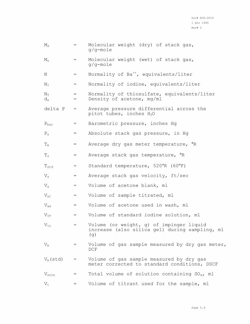
Md = Molecular weight (dry) of stack gas, g/g-mole Ms = Molecular weight (wet) of stack gas, g/g-mole N = Normality of Ba
++, equivalents/liter
NI = Normality of iodine, equivalents/liter NT = Normality of thiosulfate, equivalents/liter da = Density of acetone, mg/ml
delta P = Average pressure differential across the pitot tubes, inches H2O Pbar = Barometric pressure, inches Hg Ps = Absolute stack gas pressure, in Hg
Tm = Average dry gas meter temperature, R
Ts = Average stack gas temperature, R
Tstd = Standard temperature, 520 R (60 F)
Vs = Average stack gas velocity, ft/sec Va = Volume of acetone blank, ml Va1 = Volume of sample titrated, m1 Vaw = Volume of acetone used in wash, ml VIT = Volume of standard iodine solution, ml V1c = Volume (or weight, g) of impinger liquid increase (also silica gel) during sampling, ml
(g) Vm = Volume of gas sample measured by dry gas meter,
DCF Vm(std) = Volume of gas sample measured by dry gas meter corrected to standard conditions, DSCF Vsoln = Total volume of solution containing SOx, ml Vt = Volume of titrant used for the sample, ml
Doc# RCD.0010
1 Qtr 1990
Rev# 2
Page 5.10
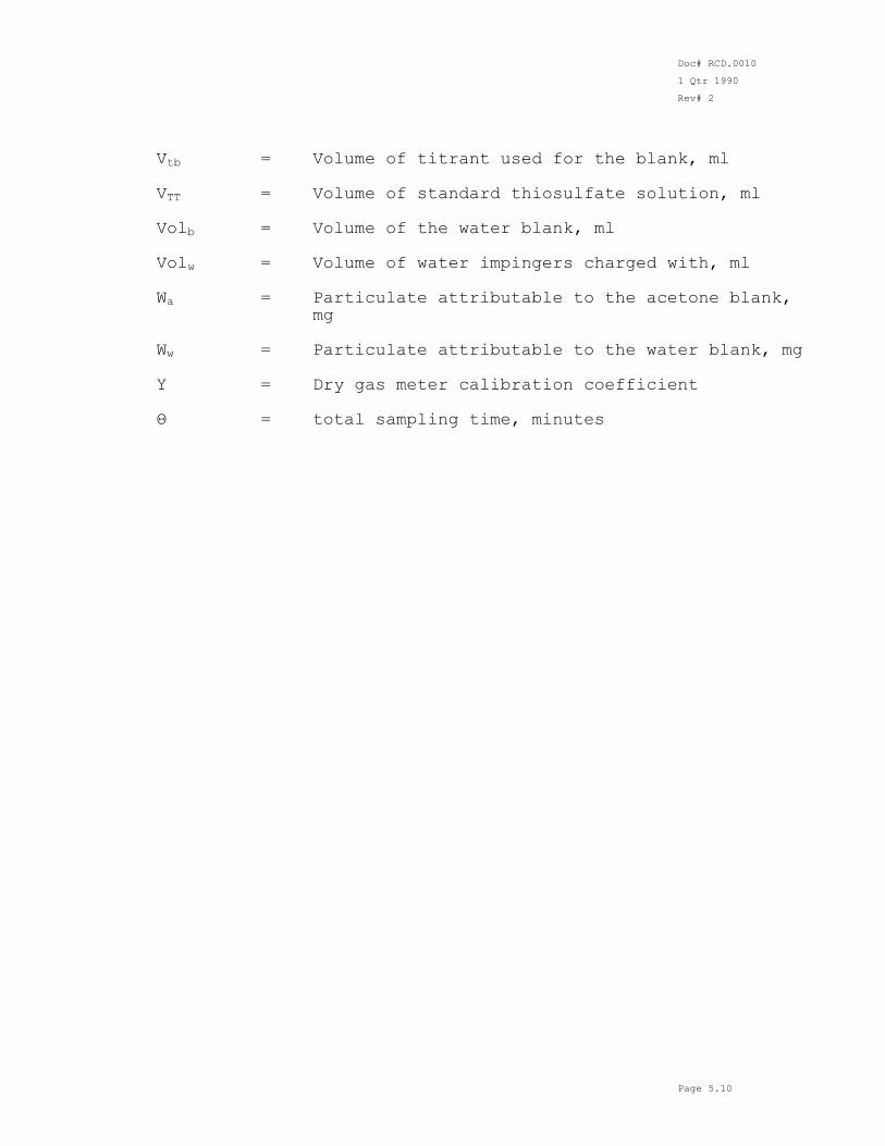
Vtb = Volume of titrant used for the blank, ml VTT = Volume of standard thiosulfate solution, ml Volb = Volume of the water blank, ml Volw = Volume of water impingers charged with, ml Wa = Particulate attributable to the acetone blank,
mg Ww = Particulate attributable to the water blank, mg
Y = Dry gas meter calibration coefficient Θ = total sampling time, minutes
Doc# RCD.0010
1 Qtr 1990
Rev# 2
Page 6.1
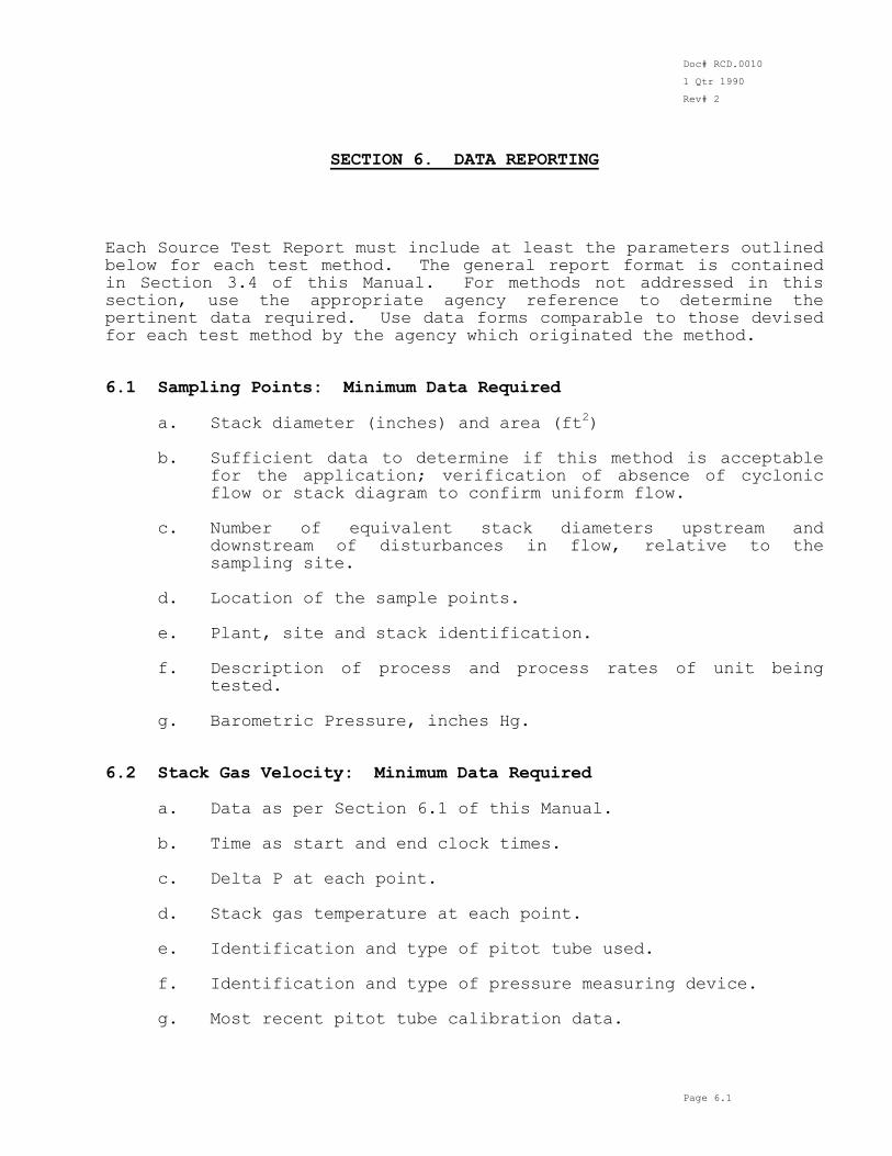
SECTION 6. DATA REPORTING Each Source Test Report must include at least the parameters outlined below for each test method. The general report format is contained in Section 3.4 of this Manual. For methods not addressed in this section, use the appropriate agency reference to determine the pertinent data required. Use data forms comparable to those devised for each test method by the agency which originated the method. 6.1 Sampling Points: Minimum Data Required a. Stack diameter (inches) and area (ft
2)
b. Sufficient data to determine if this method is acceptable
for the application; verification of absence of cyclonic flow or stack diagram to confirm uniform flow.
c. Number of equivalent stack diameters upstream and
downstream of disturbances in flow, relative to the sampling site.
d. Location of the sample points.
e. Plant, site and stack identification. f. Description of process and process rates of unit being
tested. g. Barometric Pressure, inches Hg. 6.2 Stack Gas Velocity: Minimum Data Required a. Data as per Section 6.1 of this Manual. b. Time as start and end clock times. c. Delta P at each point.
d. Stack gas temperature at each point. e. Identification and type of pitot tube used. f. Identification and type of pressure measuring device. g. Most recent pitot tube calibration data.
Doc# RCD.0010
1 Qtr 1990
Rev# 2
Page 6.2
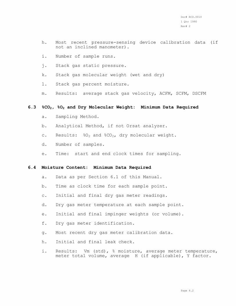
h. Most recent pressure-sensing device calibration data (if not an inclined manometer).
i. Number of sample runs. j. Stack gas static pressure. k. Stack gas molecular weight (wet and dry) l. Stack gas percent moisture. m. Results: average stack gas velocity, ACFM, SCFM, DSCFM
6.3 %CO2, %O2 and Dry Molecular Weight: Minimum Data Required a. Sampling Method. b. Analytical Method, if not Orsat analyzer. c. Results: %O2 and %CO2, dry molecular weight. d. Number of samples. e. Time: start and end clock times for sampling. 6.4 Moisture Content: Minimum Data Required a. Data as per Section 6.1 of this Manual. b. Time as clock time for each sample point. c. Initial and final dry gas meter readings. d. Dry gas meter temperature at each sample point. e. Initial and final impinger weights (or volume). f. Dry gas meter identification. g. Most recent dry gas meter calibration data.
h. Initial and final leak check. i. Results: Vm (std), % moisture, average meter temperature,
meter total volume, average H (if applicable), Y factor.
Doc# RCD.0010
1 Qtr 1990
Rev# 2
Page 6.3
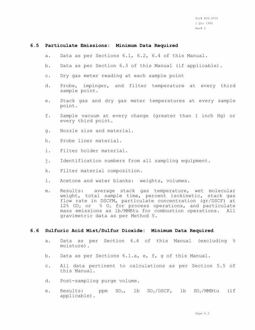
6.5 Particulate Emissions: Minimum Data Required a. Data as per Sections 6.1, 6.2, 6.4 of this Manual. b. Data as per Section 6.3 of this Manual (if applicable). c. Dry gas meter reading at each sample point d. Probe, impinger, and filter temperature at every third
sample point. e. Stack gas and dry gas meter temperatures at every sample
point.
f. Sample vacuum at every change (greater than 1 inch Hg) or
every third point. g. Nozzle size and material. h. Probe liner material. i. Filter holder material. j. Identification numbers from all sampling equipment. k. Filter material composition.
l. Acetone and water blanks: weights, volumes. m. Results: average stack gas temperature, wet molecular
weight, total sample time, percent isokinetic, stack gas flow rate in DSCFM, particulate concentration (gr/DSCF) at 12% CO2 or % O2 for process operations, and particulate mass emissions as lb/MMBtu for combustion operations. All gravimetric data as per Method 5.
6.6 Sulfuric Acid Mist/Sulfur Dioxide: Minimum Data Required a. Data as per Section 6.4 of this Manual (excluding %
moisture).
b. Data as per Sections 6.1.a, e, f, g of this Manual. c. All data pertinent to calculations as per Section 5.5 of
this Manual. d. Post-sampling purge volume. e. Results: ppm SO2, lb SO2/DSCF, lb SO2/MMBtu (if
applicable).
Doc# RCD.0010
1 Qtr 1990
Rev# 2
Page 6.4
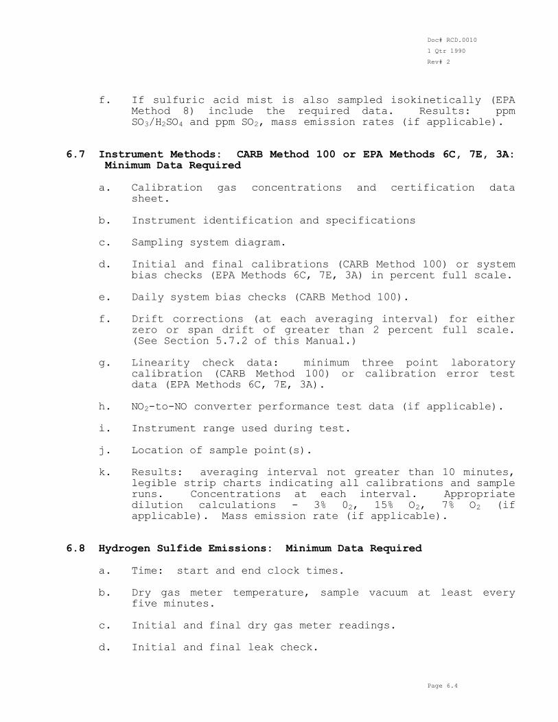
f. If sulfuric acid mist is also sampled isokinetically (EPA Method 8) include the required data. Results: ppm SO3/H2SO4 and ppm SO2, mass emission rates (if applicable).
6.7 Instrument Methods: CARB Method 100 or EPA Methods 6C, 7E, 3A:
Minimum Data Required a. Calibration gas concentrations and certification data
sheet. b. Instrument identification and specifications
c. Sampling system diagram. d. Initial and final calibrations (CARB Method 100) or system
bias checks (EPA Methods 6C, 7E, 3A) in percent full scale. e. Daily system bias checks (CARB Method 100). f. Drift corrections (at each averaging interval) for either
zero or span drift of greater than 2 percent full scale. (See Section 5.7.2 of this Manual.)
g. Linearity check data: minimum three point laboratory
calibration (CARB Method 100) or calibration error test data (EPA Methods 6C, 7E, 3A).
h. NO2-to-NO converter performance test data (if applicable). i. Instrument range used during test. j. Location of sample point(s). k. Results: averaging interval not greater than 10 minutes,
legible strip charts indicating all calibrations and sample runs. Concentrations at each interval. Appropriate dilution calculations - 3% 02, 15% O2, 7% O2 (if applicable). Mass emission rate (if applicable).
6.8 Hydrogen Sulfide Emissions: Minimum Data Required a. Time: start and end clock times. b. Dry gas meter temperature, sample vacuum at least every
five minutes. c. Initial and final dry gas meter readings. d. Initial and final leak check.
Doc# RCD.0010
1 Qtr 1990
Rev# 2
Page 6.5
e. All data pertinent to calculations as per Section 5.6 of this Manual.
f. Results: VM (std), ppm H2S. 6.9 Report Format: Minimum required See Section 3.4.6 of this Manual for minimum requirements.
Doc# RCD.0010
1 Qtr 1990
Rev# 2
Page 7.1
SECTION 7. CHAIN OF CUSTODY The primary objective of the chain of custody procedure is to create an accurate written record (see Figure 7.1 for an example chain of custody form) that can be used to trace the possession and handling of the sample from the moment of its collection through its analysis and submittal to show permit compliance. Although physical samples are not collected for all methods, general minimum guidelines for chain of custody and shipping of samples are listed below. a. Samples should be packed properly to prevent breakage or
leakage. The shipping container should be sealed or locked so that any evidence of tampering may be readily detected. Use of tamper-proof evidence tape is recommended.
b. Every sample must be accompanied by either a chain of
custody tag or a chain of custody record that has been completed, signed and dated.
c. The responsibility for proper packaging, labeling and
transferring of possession of the sample lies with the person taking it.
d. All sample shipments must be accompanied by the chain of
custody record and other pertinent forms. A copy of these
forms should be retained by the originator. Also, all receipts associated with the shipment should be retained.
e. When transferring possession of samples, the transferee
must sign and record the date and time on the chain of custody record (see Figure 7.1 for an example). In general, custody transfers are made for each sample, although samples may be transferred as a group, if desired. Each person who takes custody must fill in the appropriate section of the chain of custody record.
Doc# RCD.0010
1 Qtr 1990
Rev# 2
Page 7.1
FIGURE 7.1 Example Chain of Custody Record Person Sampling:_______________________________________________________ Date:_____________________________ Time:________________________ am/pm Facility Sampled:__________________________________________________ Facility Location:__________________________________________________
__________________________________________________ __________________________________________________ Sampling Location:__________________________________________________ __________________________________________________ __________________________________________________ Sample Type: Grab ( ) Composite ( ) Comments and/or __________________________________________________
Observations: __________________________________________________ __________________________________________________ __________________________________________________ Container I.D. __________________________________________________ Samples split? Yes ( ) No ( ) Name Affiliation/Title
Observers: _______________________________________________________ _______________________________________________________ _______________________________________________________ _______________________________________________________
Doc# RCD.0010
1 Qtr 1990
Rev# 2
Page 7.1
Affiliation/ Time/Date Rel'sd Rec'd Name Title Comments _____________ ( ) ( ) ________________________________________ _____________ ( ) ( ) ________________________________________ _____________ ( ) ( ) ________________________________________ _____________ ( ) ( ) ________________________________________ _____________ ( ) ( ) ________________________________________