Embed Size (px)
Citation preview

M362161-01 Rev J www.programmablepower.com
DLM 600W Series Power Supplies
Operation Manual
This manual covers models:
DLM 5–75
DLM 8–75
DLM 10–60
DLM 20–30
DLM 40–15
DLM 60–10
DLM 80–7.5
DLM 150–4
DLM 300–2


i
About AMETEK
AMETEK Programmable Power, Inc., a Division of AMETEK, Inc., is a global leader in the design and manufacture of precision, programmable power supplies for R&D, test and measurement,
process control, power bus simulation and power conditioning applications across diverse industrial segments. From bench top supplies to rack-mounted industrial power subsystems,
AMETEK Programmable Power is the proud manufacturer of Elgar, Sorensen, California
Instruments and Power Ten brand power supplies.
AMETEK, Inc. is a leading global manufacturer of electronic instruments and electromechanical
devices with annualized sales of $2.5 billion. The Company has over 11,000 colleagues working at more than 80 manufacturing facilities and more than 80 sales and service centers in the United
States and around the world.
Trademarks
AMETEK is a registered trademark of AMETEK, Inc.
Other trademarks, registered trademarks, and product names are the property of their respective owners and are used herein for identification purposes only.
Notice of Copyright
DLM 600W Series Power Supplies Operation Manual © August 2008 AMETEK Programmable Power, Inc. All rights reserved.
Exclusion for Documentation
UNLESS SPECIFICALLY AGREED TO IN WRITING, AMETEK PROGRAMMABLE POWER, INC.
(“AMETEK”):
(a) MAKES NO WARRANTY AS TO THE ACCURACY, SUFFICIENCY OR SUITABILITY OF ANY TECHNICAL OR OTHER INFORMATION PROVIDED IN ITS MANUALS OR OTHER
DOCUMENTATION.
(b) ASSUMES NO RESPONSIBILITY OR LIABILITY FOR LOSSES, DAMAGES, COSTS OR
EXPENSES, WHETHER SPECIAL, DIRECT, INDIRECT, CONSEQUENTIAL OR INCIDENTAL, WHICH MIGHT ARISE OUT OF THE USE OF SUCH INFORMATION. THE USE OF ANY SUCH
INFORMATION WILL BE ENTIRELY AT THE USER’S RISK, AND
(c) REMINDS YOU THAT IF THIS MANUAL IS IN ANY LANGUAGE OTHER THAN ENGLISH, ALTHOUGH STEPS HAVE BEEN TAKEN TO MAINTAIN THE ACCURACY OF THE
TRANSLATION, THE ACCURACY CANNOT BE GUARANTEED. APPROVED AMETEK CONTENT IS CONTAINED WITH THE ENGLISH LANGUAGE VERSION, WHICH IS POSTED AT
WWW.PROGRAMMABLEPOWER.COM.
Date and Revision
June 2010 Revision J
Part Number
M362161-01
Contact Information
Telephone: 800 733 5427 (toll free in North America) 858 450 0085 (direct)
Fax: 858 458 0267 Email: [email protected]
Web: www.programmablepower.com

ii
This page intentionally left blank.

iii
Important Safety Instructions
Before applying power to the system, verify that your product is configured properly for your particular application.
WARNING
Hazardous voltages may be present when covers are removed. Qualified personnel must use extreme caution when servicing this equipment. Circuit boards, test points, and output voltages also may be floating above (below) chassis ground.
WARNING
The equipment used contains ESD sensitive ports. When installing equipment, follow ESD Safety Procedures. Electrostatic discharges might cause damage to the equipment.
Only qualified personnel who deal with attendant hazards in power supplies, are allowed to perform installation and servicing.
Ensure that the AC power line ground is connected properly to the Power Rack input connector or chassis. Similarly, other power ground lines including those to application and maintenance equipment must be grounded properly for both personnel and equipment safety.
Always ensure that facility AC input power is de-energized prior to connecting or disconnecting any cable.
In normal operation, the operator does not have access to hazardous voltages within the chassis. However, depending on the user’s application configuration, HIGH VOLTAGES HAZARDOUS TO HUMAN SAFETY may be normally generated on the output terminals. The customer/user must ensure that the output power lines are labeled properly as to the safety hazards and that any inadvertent contact with hazardous voltages is eliminated.
Guard against risks of electrical shock during open cover checks by not touching any portion of the electrical circuits. Even when power is off, capacitors may retain an electrical charge. Use safety glasses during open cover checks to avoid personal injury by any sudden component failure.
Neither AMETEK Programmable Power Inc., San Diego, California, USA, nor any of the subsidiary sales organizations can accept any responsibility for personnel, material or inconsequential injury, loss or damage that results from improper use of the equipment and accessories.
SAFETY SYMBOLS

iv
This page intentionally left blank.

v
Product Family: DLM 600W Series Power Supplies
Warranty Period: Five (5) Years
WARRANTY TERMS
AMETEK Programmable Power, Inc. (“AMETEK”), provides this written warranty covering the
Product stated above, and if the Buyer discovers and notifies AMETEK in writing of any defect in material or workmanship within the applicable warranty period stated above, then AMETEK may,
at its option: repair or replace the Product; or issue a credit note for the defective Product; or provide the Buyer with replacement parts for the Product.
The Buyer will, at its expense, return the defective Product or parts thereof to AMETEK in accordance with the return procedure specified below. AMETEK will, at its expense, deliver the
repaired or replaced Product or parts to the Buyer. Any warranty of AMETEK will not apply if the
Buyer is in default under the Purchase Order Agreement or where the Product or any part thereof:
is damaged by misuse, accident, negligence or failure to maintain the same as specified or required by AMETEK;
is damaged by modifications, alterations or attachments thereto which are not
authorized by AMETEK;
is installed or operated contrary to the instructions of AMETEK;
is opened, modified or disassembled in any way without AMETEK’s consent; or
is used in combination with items, articles or materials not authorized by AMETEK.
The Buyer may not assert any claim that the Products are not in conformity with any warranty until the Buyer has made all payments to AMETEK provided for in the Purchase Order Agreement.
PRODUCT RETURN PROCEDURE
1. Request a Return Material Authorization (RMA) number from the repair facility (must be done in the country in which it was purchased):
In the USA, contact the AMETEK Repair Department prior to the return of the product to AMETEK for repair:
Telephone: 800-733-5427, ext. 2295 or ext. 2463 (toll free North America)
858-450-0085, ext. 2295 or ext. 2463 (direct)
Outside the United States, contact the nearest Authorized Service Center
(ASC). A full listing can be found either through your local distributor or our website, www.programmablepower.com, by clicking Support and going to the
Service Centers tab.
2. When requesting an RMA, have the following information ready:
Model number
Serial number
Description of the problem
NOTE: Unauthorized returns will not be accepted and will be returned at the shipper’s expense.
NOTE: A returned product found upon inspection by AMETEK, to be in specification is subject to an evaluation fee and applicable freight charges.

vi
This page intentionally left blank.

M362161-01 Rev J vii
CONTENTS
SECTION 1 GENERAL DESCRIPTION .................................................................... 1-1
1.1 Introduction ........................................................................................... 1-1
1.2 General Description .............................................................................. 1-1
1.3 Features................................................................................................ 1-2
1.4 Specifications ........................................................................................ 1-3
1.4.1 DLM Series Product Matrix ........................................................ 1-3
1.4.2 Electrical Specifications ............................................................. 1-4
1.4.3 General Characteristics ............................................................ 1-5
1.4.4 Remote Analog Interface Characteristics ................................. 1-6
1.4.5 Mechanical Characteristics ....................................................... 1-7
1.4.6 Input/Output Terminations ........................................................ 1-7
1.4.7 Regulatory Agency Compliance ................................................ 1-8
SECTION 2 INSTALLATION .................................................................................... 2-1
2.1 Introduction ........................................................................................... 2-1
2.2 Initial Inspection .................................................................................... 2-1
2.3 Location Considerations ....................................................................... 2-1
2.4 Installation/Dimensional Drawing ......................................................... 2-2
2.5 Rack Mounting...................................................................................... 2-3
2.5.1 Rack Mount Installation of a Single DLM Series 600W Unit ..... 2-4
2.5.2 Rack Mount Installation of Two DLM Series 600W Units ......... 2-6
2.6 Input Power Requirements ................................................................... 2-8
2.7 AC Line Fuses ...................................................................................... 2-8
2.8 AC Input Disconnect Device ................................................................. 2-8
2.9 Load Connections ................................................................................ 2-8
2.9.1 Wire Current Carrying Capacity ................................................. 2-9
2.9.2 Wire Voltage Drop ................................................................... 2-10
2.9.3 Noise and Impedance Effects ................................................. 2-11
2.10 Load Voltage Sensing ........................................................................ 2-11
2.10.1 Local Sensing ........................................................................ 2-11

DLM 600W Series
M362161-01 Rev J viii
2.10.2 Remote Sensing ..................................................................... 2-12
2.10.3 Remote Sense (REM SNS) Connector Pinout ....................... 2-13
2.11 Load Connection Configurations ......................................................... 2-13
2.11.1 Connecting Single Loads ....................................................... 2-13
2.11.2 Connecting Multiple Loads ..................................................... 2-15
2.12 Parallel Operation ............................................................................... 2-17
2.12.1 Parallel I/O Connector Pinout ................................................. 2-19
2.12.2 Parallel I/O Interface Functions .............................................. 2-19
2.13 Series Operation .................................................................................. 2-20
2.14 Special Application Warning ............................................................... 2-22
2.14.1 Suggested Procedure for Diode Selection ............................. 2-22
SECTION 3 OPERATION ......................................................................................... 3-1
3.1 Introduction ........................................................................................... 3-1
3.2 Controls and Indicators ......................................................................... 3-1
3.3 Initial Functional Tests .......................................................................... 3-4
3.3.1 Power–On Check ....................................................................... 3-4
3.3.2 Constant–Voltage Mode Operation Check ................................ 3-5
3.3.3 Constant–Current Mode Operation Check ................................ 3-5
3.4 Mode of Operation Setup ...................................................................... 3-6
3.4.1 Constant–Voltage Mode of Operation ....................................... 3-6
3.4.2 Constant–Current Mode of Operation ....................................... 3-7
3.4.3 Adjustment of Constant–Voltage Operation .............................. 3-7
3.4.4 Adjustment of Constant–Current Operation .............................. 3-7
3.5 OVP Operation ...................................................................................... 3-8
3.5.1 Adjustment of OVP Threshold ................................................... 3-8
3.5.2 Resetting OVP ........................................................................... 3-9
3.6 Front Panel Switches ............................................................................ 3-9
3.6.1 POWER Switch .......................................................................... 3-9
3.6.2 OUTPUT Switch ......................................................................... 3-9
3.6.3 V/I and OVP PREVIEW Switches ............................................. 3-10
3.6.4 LOCAL/REMOTE Switch ......................................................... 3-10
3.7 Reverse Polarity Protection ................................................................. 3-10
3.8 Battery Charging ................................................................................. 3-11
SECTION 4 ADVANCED OPERATION ..................................................................... 4-1
4.1 Introduction ........................................................................................... 4-1
4.2 SETUP Switch ...................................................................................... 4-1
4.2.1 SETUP Switch Functions .......................................................... 4-2

DLM 600W Series
M362161-01 Rev J ix
4.3 REMOTE ANALOG INTERFACE ......................................................... 4-3
4.3.1 REMOTE ANALOG INTERFACE Connector ............................ 4-3
4.3.2 REMOTE ANALOG INTERFACE Functions .............................. 4-4
4.4 Remote Programming .......................................................................... 4-6
4.4.1 Voltage–Source Programming of Output Voltage ..................... 4-8
4.4.2 Voltage–Source Programming of Output Current ..................... 4-9
4.4.3 Voltage–Source Programming of OVP ................................... 4-10
4.4.4 Resistance Programming of Output Voltage ........................... 4-11
4.4.5 Resistance Programming of Output Current ........................... 4-12
4.4.6 Resistance Programming of OVP ........................................... 4-13
4.5 EXTERNAL–OFF Control ................................................................... 4-14
4.5.1 EXTERNAL–OFF with Voltage Source ................................... 4-14
4.5.2 EXTERNAL–OFF with AUXILIARY 5 VDC OUTPUT.............. 4-15
4.6 Remote Monitoring ............................................................................. 4-15
4.7 Remote Digital Status Signals ............................................................ 4-16
SECTION 5 MAINTENANCE .................................................................................... 5-1
5.1 Introduction ........................................................................................... 5-1
5.2 Troubleshooting .................................................................................... 5-1
5.3 Fuse Ratings ......................................................................................... 5-3
5.4 Cleaning ............................................................................................... 5-3
5.5 Calibration ............................................................................................. 5-3
5.5.1 Internal Reference Adjustment ................................................. 5-5
5.5.2 Output Voltage Offset Adjustment ............................................ 5-5
5.5.3 Output Voltage Range Adjustment ........................................... 5-5
5.5.4 Output Current Offset Adjustment ............................................ 5-6
5.5.5 Output Current Range Adjustment ............................................ 5-6
5.5.6 Voltage Display Adjustment ...................................................... 5-7
5.5.7 Current Display Adjustment ...................................................... 5-7

DLM 600W Series
M362161-01 Rev J x
LIST OF FIGURES
Figure 2-1. DLM 600W Series Outline Drawing ................................................ 2-2
Figure 2-2. Rackmount Kit (Single Unit Option) ................................................ 2-5
Figure 2-3. Rackmount Kit (Dual Unit Option) .................................................. 2-7
Figure 2-4. Remote Sense Connector ............................................................ 2-12
Figure 2-5. Single Load Connection with Local Sensing .................................. 2-14
Figure 2-6. Single Load Connection with Remote Sensing ............................ 2-14
Figure 2-7. Multiple Load Connection with Local Sensing ................................ 2-15
Figure 2-8. Distribution Bus Connection with Remote Sensing ...................... 2-16
Figure 2-9. Parallel Connection of Units with Remote Sensing ........................ 2-17
Figure 2-10. Parallel I/O Connector ................................................................. 2-18
Figure 2-11. Series Connection of Units with Local Sensing ........................... 2-20
Figure 2-12. Series Connection of Units with Remote Sensing ...................... 2-21
Figure 2-13. Diode Selection .......................................................................... 2-22
Figure 3-1. Front and Rear Panel Views ........................................................... 3-2
Figure 3-2. CV and CC Modes of Operation ..................................................... 3-6
Figure 4-1. SETUP Switch ................................................................................ 4-1
Figure 4-2. Remote Analog Interface Connector .............................................. 4-3
Figure 4-3. Voltage–Source Programming of Output Voltage .......................... 4-8
Figure 4-4. Voltage–Source Programming of Output Current ........................... 4-9
Figure 4-5. Voltage–Source Programming of OVP ......................................... 4-10
Figure 4-6. Resistance Programming of Output Voltage ................................ 4-11
Figure 4-7. Resistance Programming of Output Current ................................ 4-12
Figure 4-8. Resistance Programming of OVP ................................................. 4-13
Figure 4-9. EXTERNAL–OFF with Voltage Source......................................... 4-14
Figure 4-10. EXTERNAL–OFF with AUXILIARY 5 VDC OUTPUT ................... 4-15
Figure 5-1. Main PWA Location of Test Points and Potentiometers ................. 5-4
Figure 5-2. Display PWA Location of Potentiometers ....................................... 5-4
LIST OF TABLES
Table 1–1. DLM Series Specifications .............................................................. 1-4
Table 2–1. DLM 600W Rackmount Kit Parts List ............................................. 2-3
Table 2–2. Wire Data ...................................................................................... 2-10
Table 2–3. Remote Sense (REM SNS) Connector Pinout .............................. 2-13
Table 2–4. Parallel I/O Connector Pinout ....................................................... 2-19
Table 4–1. Setup Switch Functions .................................................................. 4-2
Table 4–2. Remote Analog Interface Connector Pinout ................................... 4-3
Table 4–3. Remote Programming Options ....................................................... 4-7
Table 4–4. Remote Monitoring ....................................................................... 4-15
Table 4–5. Remote Digital Status Signals ....................................................... 4-16
Table 5–1. Troubleshooting Guide ................................................................... 5-2
Table 5–2. Internal Fuses ................................................................................. 5-3

M362161-01 Rev J 1-1
SECTION 1
GENERAL DESCRIPTION
1.1 Introduction
The Sorensen DLM Series of 600W power supplies comprise a family of general purpose programmable supplies for rackmount and benchtop applications. The DLM 600W series consists of nine models, rated 5V/75A, 8V/75A, 10V/60A, 20V/30A, 40V/15A, 60V/10A, 80V/7.5A, 150V/4A, and 300V/2A.
A variety of user interfaces are available, ranging from manual front–panel control and standard non–isolated remote analog control, to optional GPIB or isolated remote analog control.
1.2 General Description
The DLM series power supplies incorporate the latest power conversion and control technology to provide high accuracy, excellent regulation, low output noise, and fast transient response. They utilize a switched–mode output power converter for high efficiency and power density. The converter has been optimized to provide performance approaching that of linear supplies. A high switching frequency combined with Zero–Voltage Transition power switching and dual–stage output filtering account for the excellent dynamic and noise characteristics. Precise regulation of output voltage or current is possible with operation as either a voltage source in constant–voltage mode (CV), or as current source in constant–current mode (CC). Crossover between modes is automatic, dependent on load demand.
The front panel contains all controls and indicators required for setting and monitoring the output parameters, as well as annunciation of operational status. Individual adjustment controls are provided for output voltage, current, and over voltage protection (OVP). Two 3.5 digit LED displays normally measure the output voltage and current. In conjunction with the preview switches, these displays also show the programmed values of voltage, current, or OVP. The preview functions allow adjustment of those parameters without disturbing load connections. LED indicators show the mode of operation (CV or CC), programming control source, or abnormal operating conditions. Switches are also provided to directly control the output power, and to switch between local and remote control.

DLM 600W Series
M362161-01 Rev J 1-2
The outputs are isolated from the chassis GND. However, an internal I0M bleeder resistor is connected from output return (-) to chassis ground. This allows operation with floating outputs, or with either the negative or positive terminal of the output referenced to chassis ground.
Master/slave paralleling is possible to allow multiple units to be operated in parallel for greater output current or power. The master unit has full control of the other slave units in setting the output voltage, current, and OVP. Multiple units can be connected in series for increased output voltage, within the 300V float limitation of the output terminals.
Remote programming is available with the standard non–isolated analog interface. Output voltage, current, and OVP are fully controlled with user selectable programming voltage levels or resistance programming.
Analog output signals are also provided to monitor the output voltage and current. In addition, a complement of digital input/output signals allows control and monitoring of the operational state of the supply. Optional interfaces such as GPIB, RS-232, isolated remote analog, and LXI
TM Class C Ethernet Interface allow adaptation of the supplies to
a variety of applications.
1.3 Features
High power density, 600W, in a 1U half–rack size
Appropriate for rack or benchtop applications
Fast dynamic response: 500 s, maximum for 50% load steps
Low ripple and noise: as low as 3.5 mV(RMS) and 35 mV(PK-PK)
Universal auto–ranging AC input: 90–132V or 180–264V, without user setup
Master/slave paralleling with simple unit–to–unit control interface cable
Flexible rack mounting allowing units to be stacked in 1U increments without requiring clearance gaps between units or slides
Side–by–side mounting of two units in a 19" rack
Fast response to programming changes with active downprogrammer
Constant–voltage and constant–current modes of operation with automatic crossover and mode indicators
Two 3.5 digit displays for output voltage, current, and OVP

DLM 600W Series
M362161-01 Rev J 1-3
High resolution front panel controls for voltage and current (10–turn potentiometers), and OVP (20–turn trimmer potentiometer)
Preview switches for output voltage, current, and OVP to set parameters without disrupting load connections
Front panel OUTPUT switch for on/off control of output power
Remote sensing to compensate for voltage drop of power leads
User selectable ranges of 0–5 VDC and 0–10 VDC for programming and monitoring of output voltage and current, and for programming OVP
SETUP switch for selecting ranges for programming and monitoring signals
Opto–isolated remote shutdown for control of output power
Front panel LOCAL/REMOTE switch for selecting programming source
LOCAL–LOCKOUT function to disable front panel control while in remote operation
Digital I/O for remote control and status annunciation
Configuration changes without requiring removal of covers
Optional GPIB, LXITM
Class C Ethernet Interface, RS-232, and isolated remote analog control
Cooling fan speed control for low noise and extended fan life
1.4 Specifications
1.4.1 DLM Series Product Matrix
Model Voltage Range Current Range Power Rating
DLM 5–75 0–5 VDC 0–75 ADC 375W
DLM 8–75 0–8 VDC 0–75 ADC 600W
DLM 10–60 0–10 VDC 0–60 ADC 600W
DLM 20–30 0–20 VDC 0–30 ADC 600W
DLM 40–15 0–40 VDC 0–15 ADC 600W
DLM 60–10 0–60 VDC 0–10 ADC 600W
DLM 80–7.5 0–80 VDC 0–7.5 ADC 600W
DLM 150–4 0–150 VDC 0–4 ADC 600W
DLM 300–2 0–300 VDC 0–2 ADC 600W

DLM 600W Series
M362161-01 Rev J 1-4
1.4.2 Electrical Specifications
DLM Series Electrical Specifications1
Model DLM 5-75 DLM 8-75 DLM10-60 DLM20-30 DLM40-15 DLM60-10 DLM80-7.5 DLM150-4 DLM300-2
Output Rating:
Output Voltage
Output Current
Output Power
0-5VDC
0-75ADC
375W
0-8VDC
0-75ADC
600W
0-10VDC
0-60ADC
600W
0-20VDC
0-30ADC
600W
0-40VDC
0-15ADC
600W
0-60VDC
0-10ADC
600W
0-80VDC
0-7.5ADC
600W
0-150VDC
0-4ADC
600W
0-300VDC
0-2ADC
600W
Line Regulation2:
Voltage (0.005% of Vmax + 2mV)
Current (0.01% of Imax + 2mA)
2.4 mV
9.5 mA
2.4 mV
9.5 mA
2.5 mV
8 mA
3 mV
5 mA
4 mV
3.5 mA
5 mV
3 mA
6 mV
2.8 mA
9.5 mV
2.2 mA
17 mV
2.1 mA
Load Regulation3:
Voltage (0.005% of Vmax + 2mV)
Current (0.02% of Imax + 5mA)
2.4 mV
20 mA
2.4 mV
20 mA
2.5 mV
17 mA
3 mV
11 mA
4 mV
8 mA
5 mV
7 mA
6 mV
6.5 mA
9.5 mV
5.8 mA
17 mV
5.4 mA
Remote Voltage-Programming Accuracy
Voltage (0.25% of Vmax)
Current (.5% of Imax)
OVP (1.0% of 1.1 Vmax)
20 mV
375 mA
55 mV
20 mV
375 mA
88 mV
25 mV
300 mA
110 mV
50 mV
150 mA
220 mV
100 mV
75 mA
440 mV
150 mV
50 mA
660 mV
200 mV
38 mA
880 mV
375 mV
20 mA
1.65V
750 mV
20 mA
3.3V
Display Accuracy:
Voltage (0.5% of Vmax + 1 count)
Current (1.0% of Imax + 1 count)
35 mV
850 mA
50 mV
850 mA
60 mV
700 mA
200 mV
400 mA
300 mV
160 mA
400 mV
110 mA
500 mV
85 mA
850 mV
50 mA
2.5V
30 mA
Preview Accuracy:
Voltage (1.0% of Vmax + 1 count)
Current (1.5% of Imax + 1 count)
OVP(1.0% of 1.1 Vmax+1 count)
60 mV
1.23A
65 mV
90 mV
1.23A
98 mV
100 mV
1.0 mA
120 mV
300 mV
550 mA
320 mV
500 mV
235 mA
540 mV
700 mV
160 mA
760 mV
900 mV
120 mA
980 mV
1.6V
70 mA
1.75V
4V
40 mA
4.3V
Ripple and Noise, Voltage-Mode:
RMS (20 Hz-20 MHz)
P-P (20 Hz-20 MHz)
5 mV
30 mV
5 mV
30 mV
5 mV
30 mV
2.5 mV
15 mV
2.5 mV
15 mV
2.5 mV
20 mV
4 mV
20 mV
7 mV
40 mV
10 mV
60 mV
OVP Adjustment Range:
5% to 110% of Vmax
0.25-5.5V
0.4-8.8V
0.5-11V
1-22V
2-44V
3-66V
4-88V
7.5-165V
15-330V
DLM Series Supplemental Characteristics
Stability4:
Voltage (0.05% of Vmax)
Current (0.05% of Imax)
2.5 mV
37.5 mA
4 mV
37.5 mA
5 mV
30 mA
10 mV
15 mA
20 mV
7.5 mA
30 mV
5 mA
40 mV
3.75 mA
75 mV
2 mA
150 mV
1 mA
Temperature Coefficient5:
Voltage (0.02%/ C of Vmax)
Current (0.03%/ C of Imax)
1 mV/ C
22.5mA/ C
1.6 mV/ C
22.5mA/ C
2 mV/ C
18 mA/ C
4 mV/ C
9 mA/ C
8 mV/ C
4.5 mA/ C
12 mV/ C
3 mA/ C
16 mV/ C
2.25mA/ C
30 mV/ C
2 mA/ C
60 mV/ C
0.6mA/ C
Maximum Total Line Drop
with Remote Sensing6
1V
1V
1V
2V
2V
2V
2V
2V
2V
Notes: 1 Warranted over a temperature range of 0–50 C, with remote sensing at output terminals.
2 AC input voltage variation within the allowed range, with constant load and temperature. 3 For 0–100% load variation, with constant nominal AC input voltage and temperature. 4 Maximum drift over 8 hours with constant line, load, temperature, after 30 min. warm–up. 5 Change in output per C change in ambient temperature, with constant line and load. 6 Line drop subtracts from the maximum available output voltage at full rated power.
Table 1–1. DLM Series Specifications

DLM 600W Series
M362161-01 Rev J 1-5
1.4.3 General Characteristics
AC Input Voltage Range: 90–132 VAC or 180–264 VAC; auto–ranging, no user setup required; single–phase, 2–wire plus ground
AC Input Frequency Range: 47–63 Hz
AC Input Current: 11A, maximum at 115 VAC; 6A, maximum at 230 VAC
AC Input Power Factor: 0.6, typical at full load; dependent on the impedance of the AC input
AC Input Protection: internal fuses provided in each line of AC input for fault isolation
Operating Temperature Range: 0 C to 50 C
Storage Temperature Range: –40 C to 65 C
Humidity: 90%, maximum non–condensing
Altitude: 2,000m (6,562 ft)
Transient Response: The output voltage will recover within 500 s to the steady–state voltage level (within 0.1% of full scale) for a 50–100% or 100–50% load step change.
Efficiency: 84%, typical; 82%, typical for DLM 8–75; 75%, typical for DLM 5–75
Float Voltage: 300V(PK), maximum float voltage of either output terminal to chassis ground
Display Type: 7–segment LED, 3.5 digits for voltage, current, and OVP
Front Panel Adjustment Controls: Voltage and current controls are 10–turn precision potentiometers. OVP control is 20–turn trimmer potentiometer.
Overvoltage Protection (OVP): If the load voltage, at the point of sensing, exceeds the OVP programmed value, the output converter will be shut down, and the output capacitors will be discharged with the downprogrammer. A secondary OVP monitor senses the voltage at the rear panel output terminals to protect against open sense leads. The unit can be restarted by cycling the AC POWER switch off and back on, cycling the OUTPUT switch, or by momentarily activating the remote shutdown.

DLM 600W Series
M362161-01 Rev J 1-6
Fault Shutdown: Supervisory circuits monitor for abnormal operation of internal circuits: overtemperature, logic supply fault, paralleling interface connection fault, cooling fan fault, output converter driver fault, output converter overcurrent fault. A fault condition will result in shutdown of the output converter, and the output capacitors will be discharged with the downprogrammer. The unit can be restarted by cycling the AC POWER switch off and back on, cycling the OUTPUT switch, or by momentarily activating the remote shutdown.
Parallel Operation: Up to four units of the same model can be connected in parallel. A master/slave paralleling interface is used for forced current sharing between the units. The master unit has programming control of the output voltage, current, or OVP. The current display of each unit shows its contribution to the total load current. The voltage display of the master unit shows the load voltage, while the voltage displays of the slave units are blanked out. A fault condition occurring within a unit will result in shutdown of all units. A paralleling interface cable is used to route control signals between the units.
Series Operation: Multiple units can be connected in series, limited by the 300V(PK), maximum float voltage of the output terminals of each unit to chassis ground. The output of each unit is set individually, and each unit displays its own output voltage and current.
1.4.4 Remote Analog Interface Characteristics
Remote Voltage Programming: The output voltage, current and OVP can be programmed from zero to full scale with an external voltage source with a user–selectable range of either 0–5 VDC or 0–10 VDC. The analog programming circuitry is not isolated from the output negative (return) terminal.
Remote Resistance Programming: The output voltage, current and OVP can be
programmed from zero to full scale with an external resistance of 0–5 k . The analog programming circuitry is not isolated from the output negative (return) terminal.
Remote Resistance Programming Accuracy: Output Voltage = 1.5% of Vmax
Output Current = 2.5% of Imax
OVP = 2.0% of 1.1 Vmax
Remote Monitors: Monitors for the output voltage and current provide a proportional analog signal with user selectable ranges of 0–5 VDC or 0–10 VDC, corresponding to zero to full scale of the output parameter.
Monitor Accuracy: Voltage Monitor, 5V Range = 0.5% of Vmax
Voltage Monitor, 10V Range = 0.75% of Vmax
Current Monitor, 5/10V Ranges = 1.0% of Imax

DLM 600W Series
M362161-01 Rev J 1-7
Digital Input Signals: Digital input control signals are provided for the following functions: LOCAL–LOCKOUT and ANALOG–CONTROL. The signals are active–low,
with a logic–low output signal level of 0.8 VDC. The signals are not isolated from the negative output (return) terminal of the unit.
Digital Output Signals: Digital output control signals are provided for the following functions: VOLTAGE–MODE, REMOTE–CONTROL, OVP, and FAULT. The signals
are active–high, with a nominal 5 VDC output and a 750 source resistance. The signals are not isolated from the negative output (return) terminal of the unit.
EXTERNAL–OFF Interface: An input signal within the voltage range of 2–30 VDC turns off the output by disabling the output converter. The signal is opto–isolated from the other signals of the remote analog interface and from the output terminals of the unit. The maximum voltage between either EXTERNAL–OFF terminal and the other terminals of the REMOTE ANALOG INTERFACE is 60V(PK).
1.4.5 Mechanical Characteristics
Dimensions: 8.5 in (216 mm) W x 1.75 in (44.5 mm) H x 17 in (432 mm) D, excluding protrusion of rear panel connectors, bus bars, or terminal block.
Maximum depth, including bus bar or terminal block cover, is 18.12 in (460 mm) for low–voltage models rated 5V–60V, and 17.75 in (451 mm) for high–voltage models rated 80V–300V.
Bus bar and terminal block covers are removable from the rear panel.
Net Weight: 9.7 lbs (4.4 kg)
Shipping Weight: 12.7 lbs (5.8 kg)
Cooling: Forced convection cooling with internal fan. Fan speed is variable as a function of ambient temperature and load to extend the fan's life and reduce ambient noise. Air intake is at the front and sides of the chassis, while the exhaust is at the rear and sides of the chassis
1.4.6 Input/Output Terminations
Output Terminations: Bus bars with #10-32 screws for low–voltage models rated 5V–60V; terminal block with #6-32 screws for high–voltage models rated 80V–300V
AC Input Connector: IEC 320 male connector
AC Input Line Cord: 1.83M (6ft), nominal with IEC 320 female connector; the line cord plug is as required by destination country.
Ground Stud: A #6-32 stud is provided on the rear panel for terminations to chassis ground.

DLM 600W Series
M362161-01 Rev J 1-8
Remote Analog Interface Connector: 25–position female subminiature–D connector.
Remote Sense Connector: Two–position connector, Molex #39-30-0023.
Paralleling Interface Connector: Two six–position connectors, Molex #43045-0602, for use with the Paralleling Cable, Sorensen part number DLMP1.
1.4.7 Regulatory Agency Compliance
Units will comply with the requirements of the European Low Voltage Directive (IEC 61010-1:90+A1:92+A2:95) and EMC Directive (EN 61326:1998) as required for the CE mark.
Electrostatic Discharge: IEC 61000-4-2
Radiated RF Immunity: IEC 61000-4-3
Fast–Transients: IEC 61000-4-4
Surge: IEC 1000-4-5
Conducted RF Immunity: IEC 1000-4-6
Input Voltage Interruptions: IEC 1000-4-11
Conducted Emissions: CISPR 16-1/2
Radiated Emissions: CISPR 16-1/2
LVD Categories: Installation Category II; Pollution Degree 2; Class II Equipment; For Indoor Use Only

M362161-01 Rev J 2-1
SECTION 2
INSTALLATION
2.1 Introduction
The DLM Series power supply has been fully calibrated and tested prior to shipment; the unit is ready for immediate use upon receipt. However, when first unpacked, the unit should be inspected to ensure that no shipping damage has occurred.
2.2 Initial Inspection
Perform a visual inspection of the shipping container prior to accepting the package from the carrier. If damage to the shipping container is evident, a description of that damage should be noted on the carrier's receipt and signed by the carrier's driver.
Perform a visual inspection of the unit after it is removed from the shipping container. Check for shipping damage such as dents, scratches, distortion of the enclosure, or damaged controls. If external damage is evident, there may be internal damage as well. Immediately contact the carrier and file a claim for concealed damage. In addition, the shipping container and filler material should be saved for inspection. Forward a report of the damage to the Service Department where a customer service representative will provide instructions for repair or replacement of the unit.
2.3 Location Considerations
The power supplies are designed for rackmount and benchtop applications. As shipped, the supplies are configured for benchtop use. Conversion for rack mounting, simply requires removal of the four feet from the bottom of the chassis and adding the rackmount kit.
Since the units are fan–cooled, they require adequate clearance at the air intake and exhaust so that air flow is not impeded. The air intake is at the front and front sides, while the air exhaust is at the rear panel and rear sides. The temperature of the ambient air at the air intake should not exceed 50°C.

DLM 600W Series
M362161-01 Rev J 2-2
2.4 Installation/Dimensional Drawing
Refer to Figure 2-1 for dimensional and mounting information.
Figure 2-1. DLM 600W Series Outline Drawing

DLM 600W Series
M362161-01 Rev J 2-3
2.5 Rack Mounting
A rackmount kit, Sorensen part number DLMRK, is an option that allows mounting either one unit (see Section 2.5.1) or two units side–by–side (see Section 2.5.2) in a standard 19" rack. The chassis is designed to permit units to be stacked one on top of the other without requiring clearance gaps between the units, or the use of slides. Stacking does not restrict airflow since the top or bottom is not utilized for air intake or exhaust. Clearance slots in the chassis accept angle brackets for supporting the units in the rack without increasing the 1U (1.75") height of the chassis.
CAUTION
Four screws (two on each side), #6-32, at the front sides of the chassis are used for rackmounting. Damage could result if the penetration of screws into the chassis exceeds 0.25" (6.35 mm).
PART NO. DESCRIPTION ITEM NO. QUANTITY
9361764-01 PANEL, RACK, MNT, SGL UNIT DLM600 1 1
9361455-01 BRACKET, CHASSIS EAR MOUNT 2 2
9361912-01 BRACKET, RACK MOUNT-DLM600W 3 2
9361456-01 BAR, CHASSIS TIE MOUNT 4 1
9361916-01 BRACKET, ADPTER, RK MT-DLM600W 5 2
110DS04-04 SCREW, 6-32X, 250, SEMS, PPH, CS 6 2
112GL04-01 NUT, 10-32, W/WASHER, KEP, CS 8 4
110GS04-08 SCREW, 10-32X.500, SEMS, PPH, CS 9 8
110-032-01 SCREW, 10-32X.500, BLACK 27038 10 4
110DG20-05 SCREW, 6-32X.312, PHF, 100D, SS 11 6
Table 2–1. DLM 600W Rackmount Kit Parts List

DLM 600W Series
M362161-01 Rev J 2-4
2.5.1 Rack Mount Installation of a Single DLM Series 600W Unit
Follow the procedure below to install a single Sorensen DLM 600W Series power supply in a rack using the Rack Mount Kit, Sorensen part number DLMRK. Refer to Figure 2-2.
1. Remove the four (4) rubber feet and mounting hardware from the bottom of the unit and discard.
2. Remove the four (4) truss head screws (two on each side) from the front side
panels of the unit. (Do not discard.)
3. When rack mounting a unit, it can be mounted on the right or left hand side of the rack.
4. Install Rack Mount Extruded Ear on the front side of unit using the two (2) existing truss head screws.
5. Install Single–Unit Rack Mount Bracket on opposite side from Rack Mount Extruded Ear using the two (2) panhead SEMS screws, 6-32UNC-2A x .25” supplied in the kit.
6. Install Rack Mount Extruded Ear on end of Single–Unit Rack Mount Bracket using the two (2) existing truss head screws.
7. Position one of the two Chassis Rack Mount Brackets on the chassis side of the rack, using one of the two (2) Right Angle Adapter Brackets, if required to match existing vertical rack rail positions.
CAUTION
To prevent internal damage, use the specified screw lengths only.
Use caution when installing unit, the unit will not stay on Chassis Rack Mount Bracket until at least one of the four (4) front panel mounting screws is installed. See Figure 2-2.

DLM 600W Series
M362161-01 Rev J 2-5
Figure 2-2. Rackmount Kit (Single Unit Option)

DLM 600W Series
M362161-01 Rev J 2-6
2.5.2 Rack Mount Installation of Two DLM Series 600W Units
Follow the procedure below to install two (2) Sorensen DLM 600W Series power supplies in a rack using the Rack Mount Kit, Sorensen part number DLMRK . Refer to Figure 2-3.
1. Remove the four (4) rubber feet and mounting hardware from the bottom of the unit and discard.
2. Remove the four (4) truss head screws (two on each side) from the front side
panels on both units. (Do not discard.)
3. Install the Tie Bar onto the bottom of the two (2) inner heat sinks using the six (6) Philips flat head screws, 6-32UNC-2A X .31” supplied in the kit.
4. Install Rack Mount Extruded Ears on front sides of unit using existing four (4) truss head screws.
5. Position the two Chassis Rack Mount Brackets in the rack, use the two (2) Right Angle Adapter Brackets, if required to match existing vertical rack rail positions.
CAUTION
To prevent internal damage, use the specified screw lengths only.

DLM 600W Series
M362161-01 Rev J 2-7
Figure 2-3. Rackmount Kit (Dual Unit Option)

DLM 600W Series
M362161-01 Rev J 2-8
2.6 Input Power Requirements
The unit will operate from an AC power source rated at 90–132 VAC and 180–264 VAC, at 47–63 Hz. The AC input voltage range is automatically selected by the unit at power–up; no user setup is required.
CAUTION
Exceeding the maximum rated AC input voltage could result in damage to the unit.
An IEC connector is provided on the rear panel for connecting the unit to the AC power source with a power cord; the IEC connector also provides the safety ground termination. The power cord supplied with the unit has a safety ground wire that connects the enclosure of the unit to the safety ground of the AC power source. This connection is automatically made when the power cord is plugged into an appropriate AC receptacle.
WARNING
Operating the unit with the safety ground wire of the power cord disconnected could result in a shock hazard.
2.7 AC Line Fuses
Fuses are provided for both lines of the AC input, and are located internal to the enclosure on the main circuit board near the AC input connector. They have time–delay characteristics, and are rated at 20A/250VAC. The fuses are sized to provide fault isolation, and should not require replacement during normal operation. If the fuses open, replacement should be done by qualified personnel to determine whether a fault condition exists. Refer to Table 5–2 for fuse ratings.
WARNING
To prevent electrical shock, disconnect the AC power cord before checking the internal fuses. Operating with fuses of improper rating could result in a fire hazard.
2.8 AC Input Disconnect Device
The front panel POWER switch does not disconnect the AC input line from the unit. Ensure that access is provided to the rear panel IEC AC input connector or the plug of the line cord. For rack mount applications, ensure that a suitable disconnecting device is incorporated that will provide isolation from the AC input source.
2.9 Load Connections
Low–voltage models rated 5V–60V have bus bars at the rear of the unit for connecting the load; refer to Figure 3-1. The bus bars are protected with a two–piece cover. The

DLM 600W Series
M362161-01 Rev J 2-9
top portion of the cover is removable to allow access to the bus bar screws. In addition, the top portion has scored sections at the top and back that could be removed to provide a larger opening for wiring.
Ensure that wires are routed appropriately to prevent shorting, and that the cover is properly installed before applying AC power to the unit. For applications where the bus bars are not operator accessible, such as rack mounting, both portions of the cover could be removed. Ensure that adequate protection from accidental contact is provided for service personnel that might work on the equipment.
High–voltage models rated 80V–300V have an output terminal block with a snap–on cover. Ensure that the cover is in place, and that it insulates all connections to the output terminals before operating the unit.
WARNING
To prevent electrical shock, disconnect the AC power cord before making any connections to the unit.
CAUTION
If longer bus bar screws are substituted, ensure that a clearance of at least 0.125” (3.2 mm) exists to the rear panel to prevent an electrical short.
When connecting the load to the power supply, consider the following factors to select a suitable wire gauge: the current carrying capacity of the wire (limited by temperature rise of the wire); the voltage drop across the total length of load lines; noise coupling and impedance effects of the load lines.
2.9.1 Wire Current Carrying Capacity
Load wiring must have a current carrying capacity greater than the output current rating of the power supply. This ensures that the wiring will not be damaged even if the load is shorted.
Table 2–2 shows the current rating, based on 500A/cm2, for various gauges of wire.
The maximum current that a particular wire can conduct is dependent on multiple factors: ambient temperature, temperature rating of insulation, wire bundling, and altitude. The primary constraint is that the temperature rise of the wire resulting from the current flow, added to the ambient temperature, must not exceed the maximum operating temperature of the insulation.

DLM 600W Series
M362161-01 Rev J 2-10
AWG Copper Area,
cm2
Resistance,
/m at 20°C
Resistance,
/m at 100°C
Current Rating,
A at 500A/cm2
6 0.133 0.0013 0.0017 66.5
8 0.0837 0.0021 0.0028 41.9
10 0.0526 0.0033 0.0044 26.3
12 0.0331 0.0052 0.0069 16.6
14 0.0208 0.0083 0.011 10.4
16 0.0131 0.0132 0.0174 6.6
18 0.00823 0.0209 0.0276 4.1
20 0.00518 0.0333 0.044 2.6
22 0.00326 0.053 0.07 1.6
Table 2–2. Wire Data
2.9.2 Wire Voltage Drop
For applications where regulation is important, the contribution of the load wiring to voltage drop from the power supply output terminals to the load must be considered. The wire gauge must be selected to maintain an acceptable total voltage drop of the load wiring under the maximum peak current. The resistance of the load wiring must be determined for the sum total length of the positive lead and the negative lead.
Table 2–2 gives the resistance per meter (m) of various wire gauges at 20°C and 100°C. Use the following equation to calculate resistance for other wire temperatures:
R = R20°C [1 + 0.004 (T-20°C)]
Where R = resistance, /m, at temperature T
R20°C = resistance, /m, at 20°C
T = temperature, °C, of wire
The voltage drop (per positive or negative lead) can be calculated using the following equation:
V = I L R20°C [1 + 0.004 (T-20°C)]
Where V = total voltage drop, V
I = load current, A
L = length, m, of load wire
R20°C = resistance, /m, of wire at 20°C
T = temperature, °C, of wire conducting load current
The total voltage drop would be calculated by summing the drops of the positive and negative leads.

DLM 600W Series
M362161-01 Rev J 2-11
2.9.3 Noise and Impedance Effects
To minimize noise pickup or radiation from load circuits, load wires and remote sense wires should be twisted–pair with minimum lead length. Shielding of the sense leads may be necessary in high noise environments. Even if noise is not a concern, the load and remote sense wires should be twisted–pairs to reduce coupling between them, which could impact the stability of the power supply. If connectors are utilized for the power and sense leads, be careful not to introduce coupling between the leads. Ensure that the connector terminals for the sense leads are in adjacent locations, and minimize the physical loop area of the untwisted portions. Ideally, the sense leads should be separated from the power leads and should have their own connector.
Twisting the load wires provides an additional benefit in reducing the parasitic inductance of the cable. This improves the dynamic response characteristics at the load by maintaining a low source impedance at high frequencies. Also, with long load wires, the resultant inductance and resistance could produce high frequency voltage spikes at the load because of current variations in the load itself. The impedance introduced between the output of the power supply and the load could make the ripple/noise at the load worse than the specifications of the power supply (which are valid when measured at the rear panel bus bars). Additional filtering with bypass capacitors at the load terminals may be required to bypass the high frequency load currents.
In addition, when operating with external sense, the recommendation is that it be done
with twisted shielded pair, with one end of the shielding connected to the ground stud next to the sense connector. The other end does not need to be connected.
2.10 Load Voltage Sensing
Two methods are available for sensing the load voltage: local and remote sensing. Local sensing measures the voltage internal to the supply at the output terminals. Remote sensing allows the point of measurement to be relocated to the load.
2.10.1 Local Sensing
Local sensing is the default factory setting, and results in sensing the output voltage internally at the rear panel output terminals. To select this method of sensing, ensure that REM SNS of the SETUP switch, Position-1, is set to OFF. Refer to Figure 4-1.

DLM 600W Series
M362161-01 Rev J 2-12
2.10.2 Remote Sensing
Remote sensing is used during voltage–mode operation to compensate for the voltage drop across the load wires. It is selected by setting REM SNS of the SETUP switch, Position-1, to ON. Refer to Figure 4-1.
A separate pair of wires is routed to measure the voltage at the load instead of the local connection at the output terminals. Refer to Figure 2-4 for a view of the connector, and Table 2–3 for its pinout. Connect the positive and negative terminals of the sense leads to the respective terminals of the load.
Special care is required in routing the sensing leads to prevent noise pickup or coupling to the power leads; refer to Section 2.9.3, Noise and Impedance Effects. The sense leads should be a twisted–pair of at least AWG #22 wire, and may require shielding in high noise environments. Connect the shield at only one point, as required to maximize its effectiveness.
If the unit is set for remote sense (i.e., SETUP switch Position-1 is ON), but the sense wires to the load are not connected, the unit will revert to local sense. This will also cause the output voltage, at the rear panel output terminals, to increase nominally 5% above the programmed value.
If remote sensing is enabled, but the sense leads are not connected to the output, the power supply will shut down due to OVP. Also, if excessive line drop occurs in the load wires, an OVP shutdown could be generated because of the secondary OVP circuit that monitors for abnormal voltage at the rear panel output terminals.
Figure 2-4. Remote Sense Connector

DLM 600W Series
M362161-01 Rev J 2-13
2.10.3 Remote Sense (REM SNS) Connector Pinout
The REMOTE SENSE (REM SNS) connector is a 2–position connector, Molex #39-30-0023. The mating connector is Molex #39-01-3022; and its terminals are Molex #39-00-0056. The pinout is presented in Table 2–3.
Pin Number Function
1 Negative (–) Sense
2 Positive (+) Sense
Table 2–3. Remote Sense (REM SNS) Connector Pinout
2.11 Load Connection Configurations
The output of the DLM Series power supplies is isolated (see Note) from chassis ground, allowing either positive, negative, or floating outputs with respect to chassis ground. Connections to the load are made at the rear panel output terminals. Ensure that a wire gauge is utilized that can carry the programmed current without overheating. Either local or remote sensing of the output voltage is selectable, depending upon the desired point of voltage regulation.
(Note: There is a I0M resistor network connected from the output return(-) to the chassis ground).
WARNING
The REMOTE ANALOG INTERFACE, REMOTE SENSE, and PARALLEL I/O signals are connected to the negative (return) output terminal. If the negative (return) output terminal is floated with respect to chassis ground, those signals will also float at the same potential. Use appropriate safety measures to prevent a shock hazard.
CAUTION
Operating the power supply with either the positive or negative output lead floated greater than 300 VPK above chassis ground could result in damage to the unit.
2.11.1 Connecting Single Loads
Single loads are connected directly to the rear panel output terminals. Twist the load wires or maintain them closely in parallel for their entire length. Use the heaviest gauge practical to minimize line drop. Figure 2-5 and Figure 2-6 show single load connections with local and remote sensing, respectively.

DLM 600W Series
M362161-01 Rev J 2-14
Figure 2-5. Single Load Connection with Local Sensing
*SETUP Switch Position-1, REM SNS, Set to ON
Figure 2-6. Single Load Connection with Remote Sensing

DLM 600W Series
M362161-01 Rev J 2-15
2.11.2 Connecting Multiple Loads
When output voltage regulation is critical and multiple loads are connected to the power supply, it is important to connect each load independently to the terminals where the output voltage is sensed. Independent leads to each load will ensure that the load currents do not produce voltage drops in the connecting leads that could be mutually coupled between the loads. Figure 2-7 shows two loads connected to the power supply, with local sensing.
Figure 2-7. Multiple Load Connection with Local Sensing
If a distribution bus is utilized for multiple loads, the point of voltage sensing is important to ensure that the voltage regulation is acceptable for all of the loads. In general, remote sensing is used and the point of sensing is selected to minimize interaction of the various loads through line drops caused by their load currents. Figure 2-8 shows multiple loads connected with a distribution bus; remote sensing is used at the point where the power leads connect to the distribution bus.

DLM 600W Series
M362161-01 Rev J 2-16
*SETUP Switch Position-1, REM SNS, Set to ON (1) For best performance use twisted shielded pair.
Figure 2-8. Distribution Bus Connection with Remote Sensing
(1)

DLM 600W Series
M362161-01 Rev J 2-17
2.12 Parallel Operation
Up to four power supplies of the same model can be connected in parallel. The paralleled supplies operate in a master/slave configuration, where the master controls the output voltage and total current, and provides control signals to the slaves to set their output current. The master and slave supplies will share the output current equally. Either local or remote sensing can be used.
Figure 2-9 shows a parallel connection of two units with remote sensing.
CAUTION
The outputs of paralleled units must be wired in parallel at the rear panel output terminals of the units. Use the shortest practical cable length. Operation of a unit without a negative (return) connection could result in damage.
Figure 2-9. Parallel Connection of Units with Remote Sensing

DLM 600W Series
M362161-01 Rev J 2-18
Setup for the parallel configuration is as follows:
1. Connect the outputs of the units in parallel at the rear panel output terminals using short cable lengths. Connect the load wires to the output terminals of the master unit.
2. Interconnect the master and slave units with the PARALLELING CABLE, Sorensen part number DLMP1. Either of the two rear panel PARALLEL I/O connectors can be used, as they are pinned out the same. Refer to Figure 2-10 for an illustration of the PARALLEL I/O connector and Table 2–4 for pinout information.
Figure 2-10. Parallel I/O Connector
3. For the slave units, select the slave mode by turning ON the SLAVE position (Position–2) of the SETUP switch. The master unit must have the SLAVE position (Position–2) of the SETUP switch set to OFF.
4. Adjust the OVP setting of the slave unit to full scale.
5. The voltage, current, and OVP are adjusted with the controls of the master unit. The voltage display of the slave units will be blanked out. The current displays of all units must be summed to derive the total load current.
6. The OUTPUT switch of the master unit will turn off all of the units. The OUTPUT switch of a slave unit will turn off only its output; the remaining units will continue to operate and will assume that portion of the load supplied by the slave unit.
7. Turning off the POWER switch of any unit will result in shutdown of all units.
8. A shutdown occurring in any unit (resulting from a fault, OVP, overtemperature, or loss of AC power) will result in shutdown of all units.
9. External control through the REMOTE–ANALOG INTERFACE and interface selections with the SETUP switch are done with the master unit.

DLM 600W Series
M362161-01 Rev J 2-19
2.12.1 Parallel I/O Connector Pinout
The PARALLEL I/O connector is a 6–position connector, Molex #43045-0602. The mating connector is Molex #43025-0600; and, its terminals are Molex #43030-0009. The pinout is presented in Table 2–4.
Pin Number Function
1 Parallel Drive Bus
2 Parallel Drive Return
3 Parallel Disable Bus
4 Parallel Disable Return
5 Not Used
6 Not Used
Table 2–4. Parallel I/O Connector Pinout
2.12.2 Parallel I/O Interface Functions
The PARALLEL I/O INTERFACE provides control signals for implementing the master/slave paralleling of multiple units. The following sections describe the functions of the various signals. Pin numbers correspond to the PARALLEL I/O INTERFACE connector pinout; also refer to Table 2–4.
PARALLEL DRIVE: Pin-1, output signal of a master unit and input signal of slave units used for programming the slave units. Signal is not isolated from the negative (return) output of the unit.
PARALLEL DRIVE RETURN: Pin-2, return for PARALLEL DRIVE signal. Signal is not isolated from the negative (return) output of the unit.
PARALLEL DISABLE: Pin-3, active–low control signal common to both master and slave units that will force all units to shut down if any one of the units shuts down. Signal is not isolated from the negative (return) output of the unit.
PARALLEL DISABLE RETURN: Pin 4, return for PARALLEL DISABLE signal. Signal is not isolated from the negative (return) output of the unit.
Unused Pins: Pin 5 and Pin 6.

DLM 600W Series
M362161-01 Rev J 2-20
2.13 Series Operation
Multiple units of the same model can be connected in series to obtain a higher output voltage, within the limits of the 300V(PK) maximum float potential. The supplies are interconnected with the negative terminal of one supply being connected to the positive terminal of other.
The output voltage is derived from the positive and negative terminals of the total string. Each supply is individually adjusted, with the total output voltage being the sum of the individual outputs. The output current is the same for each unit. Either local or remote sensing can be used.
Figure 2-11 shows the series connection of two units with local sensing. Figure 2-12 shows the series connection of two units with remote sensing.
CAUTION
To prevent damage to a supply, do not connect the remote sense leads of one supply across the total series string.
Figure 2-11. Series Connection of Units with Local Sensing

DLM 600W Series
M362161-01 Rev J 2-21
Figure 2-12. Series Connection of Units with Remote Sensing

DLM 600W Series
M362161-01 Rev J 2-22
2.14 Special Application Warning
The DLM600 family of supply requires freewheeling and blocking diodes while driving inductive loads or batteries to protect the power supply from damage caused by power being fed back into the supply and from high voltage transients.
2.14.1 Suggested Procedure for Diode Selection
The Peak Reverse Voltage ratings should be a minimum of 2-3 times the Power Supply maximum output voltage. The Continuous Forward Current ratings should be a minimum of 1.5 times the Power Supply maximum output current. Heatsink may be required. There also may be a need for higher voltage rated parts, dependent on load circuit design and inductor values.
Figure 2-13. Diode Selection

M362161-01 Rev J 3-1
SECTION 3
OPERATION
3.1 Introduction
The DLM Series power supplies have a full complement of controls, indicators, and connectors that allow the user to easily install, setup, and operate the unit.
3.2 Controls and Indicators
Refer to Figure 3-1 for an illustration of the front and rear panel controls and indicators.
1. VOLTAGE Display: 3.5 digit, 7–segment LED display that normally indicates the output voltage. When the V/I PREVIEW switch is pressed, the display indicates the programmed setting of output voltage. When the OVP PREVIEW switch is pressed, the display indicates the programmed setting of OVP.
2. CURRENT Display: 3.5 digit 7–segment LED display that normally indicates the output current. When the V/I Preview switch is pressed, the display indicates the programmed setting of output current.
3. VOLTAGE Control: 10–Turn potentiometer for adjusting the output voltage.
4. CURRENT Control: 10–Turn potentiometer for adjusting the output current.
5. OVP SET Control: 20–Turn trimmer potentiometer for adjusting overvoltage protection.
6. POWER Switch: Push–on/Push–off switch for turning the unit on and off.
7. OUTPUT Switch: Push–on/Push–off switch for turning the output on and off.
8. V/I PREVIEW Switch: Momentary push–button switch for previewing the programmed settings of output voltage and current. The programmed setting is derived from the front panel controls, the analog interface, or the GPIB interface, whichever has control.

DLM 600W Series
M362161-01 Rev J 3-2
Figure 3-1. Front and Rear Panel Views

DLM 600W Series
M362161-01 Rev J 3-3
9. OVP PREVIEW Switch: Momentary push–button switch for previewing the programmed setting of OVP. The programming signal is derived from the front panel control, the analog interface, or the GPIB interface, whichever has control.
10. LOCAL(REMOTE) Switch: Momentary push–button switch for selecting local front–panel control while in GPIB remote operation, or toggling between the front–panel and remote analog programming when analog interface is used. Lockout function could be utilized, for both the GPIB and analog interface, to disable the front panel controls when using remote control.
11. REM (Remote) Indicator: Green LED lights when in remote programming mode, either GPIB or analog interface.
12. OUTPUT Indicator: Green LED lights when the DC output is enabled.
13. VOLTAGE Indicator: Green LED lights for the constant–voltage mode of operation.
14. CURRENT Indicator: Green LED lights for the constant–current mode of operation.
15. OVP (Overvoltage Protection) Indicator: Red LED lights for tripped OVP; the output is also turned off.
16. FAULT Indicator: Red LED lights for overtemperature shutdown or summary fault condition; the output is also turned off.
17. EXT OFF (External Off) Indicator: Green LED lights when the output is turned off using the remote shutdown signal of either the remote analog interface or the GPIB interface.
18. AC Line Input: IEC connector for the AC input power cord.
19. POSITIVE DC Output: For low–voltage models rated 5V–60V, bus bar, with #10-32 screw.
20. NEGATIVE DC Output: For low–voltage models rated 5V–60V, bus bar, with #10-32 screw.
21. ANALOG INTERFACE Connector: Connector for remote analog interface, comprising programming, monitoring, and digital input/output control signals.
22. REMOTE SENSE (REM SNS) Connector: Connector for making remote connections to the load for regulation of its voltage and compensation of line drop. Positive (+) terminal is connected to positive load terminal and negative (–) terminal is connected to negative load terminal.

DLM 600W Series
M362161-01 Rev J 3-4
23. PARALLEL I/O Connector: Two connectors used for configuring multiple power supplies for parallel operation with master/slave control. Both connectors have the same pinout and can be used interchangeably. The designation of master and slaves is selected with the SETUP switch.
24. SETUP Switch: Eight–section switch for selecting remote sensing, slave unit, and 0–5 VDC or 0–10 VDC voltage ranges for programming and monitoring.
25. Ground Stud: #6-32 stud for chassis ground connection.
26. POSITIVE DC Output: For high–voltage models rated 80V–300V, terminal block, with #6-32 screws.
27. NEGATIVE DC Output: For high–voltage models rated 80V–300V, terminal block, with #6-32 screws.
3.3 Initial Functional Tests
3.3.1 Power–On Check
1. Ensure that the POWER and OUTPUT switches are in the OFF position (switch buttons out).
2. Ensure that there are no connections to the REMOTE ANALOG INTERFACE connector, and that all positions of the SETUP switch are OFF (switches down).
3. Turn the controls for the VOLTAGE and CURRENT fully counter–clockwise.
4. Turn the control for OVP fully clockwise.
5. Connect the power cord to an AC power source
6. Turn the front panel POWER switch to the ON position (switch button in). The power supply will execute the power–up routine for approximately 7 seconds: all LED indicators will be on; all display LED segments will be on; the internal fans will run at maximum speed; the OVP and FAULT monitors will be reset.
7. After power–up, ensure that both of the front panel digital displays are on and that both of the displays indicate zero. Also, the following LED indicators should be off: OVP, FAULT, EXT–OFF, REM and OUTPUT.
8. Turn the POWER switch ON.
9. Turn the control for the CURRENT fully clockwise.
10. Ensure that the VOLTAGE indicator is on and that the CURRENT indicator is off.

DLM 600W Series
M362161-01 Rev J 3-5
3.3.2 Constant–Voltage Mode Operation Check
1. Ensure that the front panel POWER and OUTPUT switches are in the OFF position (switch buttons out).
2. Connect a digital voltmeter (DVM) to measure the voltage at the output terminals
3. Turn the VOLTAGE control on the front panel fully counter–clockwise.
4. Turn the CURRENT control on the front panel fully clockwise.
5. Turn the front panel POWER and OUTPUT switches to the ON position (switch buttons in).
6. Slowly turn the control for the VOLTAGE clockwise and observe the values of the VOLTAGE display and the DVM. Adjust the control for the VOLTAGE across its full range.
7. Compare the DVM reading with the front panel display reading to verify the accuracy of the front panel display for VOLTAGE.
8. Ensure that the control for VOLTAGE adjusts the output voltage across the full rated voltage range. Also, the VOLTAGE indicator should be on and the CURRENT indicator should be off.
3.3.3 Constant–Current Mode Operation Check
1. Ensure that the front panel POWER and OUTPUT switches are in the OFF position (switch buttons out).
2. Connect a DC shunt across the output terminals. Ensure that the rating of the DC shunt and the connecting wire exceed the output current capability of the power supply.
3. Connect a digital voltmeter (DVM) across the DC shunt.
4. Turn the CURRENT control on the front panel fully counter–clockwise.
5. Turn the VOLTAGE control on the front panel fully clockwise.
6. Turn the front panel POWER and OUTPUT switches to the ON position (switch buttons in).
7. Turn the control for the CURRENT slowly clockwise and observe the values of the CURRENT display and the DVM. Adjust the control for the CURRENT across its full range.

DLM 600W Series
M362161-01 Rev J 3-6
8. Compare the DVM reading with the front panel display reading to verify accuracy of the front panel display for CURRENT. The DVM reading must be converted to current by multiplying the DVM reading by a conversion factor equal to the DC current rating of the shunt divided by the burden voltage rating of the shunt.
9. Ensure that the control for CURRENT adjusts the output current across the full rated current range. Also, the CURRENT indicator should be on and the VOLTAGE indicator should be off.
3.4 Mode of Operation Setup
The power supply is capable of operating in constant–voltage or constant–current mode. The mode of operation is dependent on the settings of the VOLTAGE and CURRENT controls and resistance of the load. The power supply can automatically crossover between the two modes of operation in response to load demands; refer to Figure 3-2. The mode of operation is indicated with front panel LED's: VOLTAGE for constant–voltage and CURRENT for constant–current.
Figure 3-2. CV and CC Modes of Operation
3.4.1 Constant–Voltage Mode of Operation
The power supply will operate in constant–voltage mode whenever the load current is less than the current setting. In this mode, the power supply maintains the output voltage precisely regulated to the voltage setting while the load current varies with the load requirements. This condition is maintained as long as the load current is less than the current setting. If the load resistance decreases to where the load current attempts to exceed the current setting, the output current is then regulated at the set value and the output voltage decreases. This is the automatic crossover to constant–current mode of operation.

DLM 600W Series
M362161-01 Rev J 3-7
3.4.2 Constant–Current Mode of Operation
The power supply will operate in constant–current mode whenever the load resistance times the current limit setting is less than the voltage setting. In this mode, the power supply maintains the output current precisely regulated to the current setting while the load voltage varies with load requirements. This condition is maintained as long as the load resistance is less than the voltage setting divided by the current setting. If the load resistance increases to where the load voltage attempts to exceed the voltage setting, the output voltage is then regulated to the set value and the output current decreases. This is the automatic crossover to constant–voltage mode of operation.
3.4.3 Adjustment of Constant–Voltage Operation
Follow these steps to set the power supply for constant–voltage mode of operation:
1. Turn the front panel POWER switch to the ON position and the OUTPUT switch to the OFF position.
2. Press in the V/I PREVIEW switch to display the programmed setting of the output voltage and current. Set the displayed values to the desired output voltage and an output current that would exceed the load current. The current setting must be greater than the maximum peak current required by the load. If the load current attempts to exceed the limit value, the power supply will enter the constant–current mode of operation: The output voltage will decrease and no longer will be regulated.
3. Turn the front panel OUTPUT switch to the ON position. The VOLTAGE indicator should be ON and the CURRENT indicator should be OFF.
3.4.4 Adjustment of Constant–Current Operation
Follow these steps to set the power supply for constant–current mode of operation:
1. Turn the front panel POWER switch to the ON position and the OUTPUT switch to the OFF position.
2. Press in the V/I PREVIEW switch to display the programmed setting of the output voltage and current. Set the displayed values to the desired output current and an output voltage that would exceed the maximum compliance voltage required by the load. The voltage setting must be greater than the maximum peak voltage required by the load. If the load voltage attempts to exceed the limit value, the power supply will enter the constant–voltage mode of operation: The output current will decrease and no longer will be regulated.
3. Turn the front panel OUTPUT switch to the ON position. The CURRENT indicator should be ON and the VOLTAGE indicator should be OFF.

DLM 600W Series
M362161-01 Rev J 3-8
3.5 OVP Operation
The OVP monitor provides protection from overvoltage conditions that could be generated at the load due to improper adjustment of the output voltage or malfunction of the unit. Provisions are available to set the OVP threshold either with the front panel controls or remotely through the analog interface (or, through the optional GPIB interface).
The monitor measures the output voltage at the point where the sense leads are connected: either internally at the output terminals or at the remote sense leads, depending on which method of sensing is selected. If remote sensing is selected, a secondary monitor measures the voltage at the output terminals, in addition to the primary monitor measuring the load voltage. This provides protection in case the remote sense leads are disconnected.
When the OVP is tripped, the output converter is turned off and the output capacitors are discharged with a downprogrammer. In addition, the front panel OVP indicator is turned on.
3.5.1 Adjustment of OVP Threshold
Use the following procedure to set the OVP threshold:
1. Turn the front panel POWER switch to the ON position and the OUTPUT switch to the OFF position.
2. Press in the V/I PREVIEW switch to display the programmed setting of the output voltage and current. Set the displayed values to the desired output voltage and current.
3. Press in the OVP PREVIEW switch to display the programmed setting of the OVP threshold. Ensure that the OVP setting exceeds the setting of the output voltage; otherwise, the OVP will be tripped as soon as the POWER switch is turned ON.
4. OVP operation is verified as follows: set the OVP threshold to less that full scale output voltage rating of the power supply; set the output voltage to less than the OVP threshold; turn POWER switch ON; adjust output voltage so that OVP threshold is exceeded; output will shut down and OVP indicator will be turned on when OVP threshold is reached.

DLM 600W Series
M362161-01 Rev J 3-9
3.5.2 Resetting OVP
Perform the following to reset the OVP monitor if it has been activated:
1. Reduce the power supply’s output voltage to below the OVP threshold.
2. Ensure that the connections for the power and sense leads are correct.
3. The OVP monitor is reset by toggling OFF and then back ON either of the following switches or signals: the OUTPUT switch, the POWER switch, the EXTERNAL–OFF signal of the REMOTE ANALOG INTERFACE, or through the optional GPIB interface.
3.6 Front Panel Switches
3.6.1 POWER Switch
The POWER switch turns on the autoranging AC input rectifier and the control circuits of the unit. It initiates a power–up routine (approximately 7 seconds in duration) that performs an indicator/display test, high speed fan start–up, and range setting of the rectifier.
The POWER switch does not disconnect the AC input lines from the unit; therefore, the input filter networks remain connected when the switch is turned off.
3.6.2 OUTPUT Switch
The OUTPUT switch turns the output converter on and off. It will also reset the OVP and FAULT monitors when it is toggled off and then back on.
When the switch is turned off, the downprogrammer is enabled to discharge the output capacitors. After a time delay, the downprogrammer is turned off, and the output of the unit becomes a high impedance. The switch does not disconnect the load from the output of the unit; therefore, the output filter capacitors and bleeder resistance remain connected when the switch is turned off.
When multiple units are operated in parallel, the switch functions differently for the master unit as compared to the slaves. The OUTPUT switch of the master unit will turn all units off, and each unit will discharge its output filter capacitors. However, the OUTPUT switch of the slave units will only turn off their individual outputs; also, the downprogrammer of the slaves will not be turned on.

DLM 600W Series
M362161-01 Rev J 3-10
3.6.3 V/I and OVP PREVIEW Switches
The V/I and OVP PREVIEW switches allow the front panel displays to show the programmed values for the output voltage, current, and OVP. They can be used to set the output parameters prior to turning on the output, and without disturbing the load connections. In addition, they allow checking the settings after the output is enabled. The preview functions remain operational when remote control is selected, either the analog or GPIB interface.
3.6.4 LOCAL/REMOTE Switch
The LOCAL/REMOTE switch allows selecting either the front panel controls or the remote interface for programming the output voltage, current, or OVP. A remote interface (either analog or GPIB) must be enabled for the switch to be functional.
With the REMOTE ANALOG INTERFACE, the switch provides a toggle function to alternate between the programmed settings of the front panel and analog interface every time it is pressed. The REM front panel indicator is turned on when control is through the analog interface. The LOCAL–LOCKOUT control signal of the interface could be used to disable the toggling and maintain remote control.
When the GPIB interface is enabled, pressing the switch will transfer control to the front panel; however, toggling will not occur if it is pressed again. The GPIB controller must issue a command to the power supply before control will revert to the GPIB. A local–lockout function is also available with the GPIB interface.
3.7 Reverse Polarity Protection
The output of the power supply is protected against reverse polarity sources connected to the output terminals. The output terminals have diodes connected directly across them. If the voltage at the output were to reverse in polarity, the diodes would conduct and clamp it to a forward voltage drop, of approximately 1V.

DLM 600W Series
M362161-01 Rev J 3-11
3.8 Battery Charging
When using a power supply to charge a battery, the following precautions should be taken:
1. Connect an isolation diode in series with one of the output terminals of the power supply. This diode will prevent discharge of the battery if the power supply were to be turned off. The diode must have suitable current and voltage ratings and should be mounted on an appropriate heat sink.
2. Adjust the VOLTAGE setting to the desired float voltage using the V/I PREVIEW switch or with the power supply disconnected from the battery. The VOLTAGE setting should compensate for the voltage drop of the isolation diode, if local sensing is used.
3. Adjust the CURRENT setting to the desired current limit value when charging a battery.
When recharging a battery, the power supply will initially operate in constant–current mode, regulating the output current to the current set value. As the battery charges, the battery voltage increases until the float voltage setting is reached. Then, the power supply enters the constant–voltage mode of operation, regulating the output voltage at the float voltage setting. The battery current decreases from the current set value, and eventually drops to a low float current level when the battery is fully charged.

DLM 600W Series
M362161-01 Rev J 3-12
This page intentionally left blank.

M362161-01 Rev J 4-1
SECTION 4
ADVANCED OPERATION
4.1 Introduction
The DLM Series power supplies provide extended configuration and interface capabilities to allow them to be adapted for special applications. The SETUP switch allows selection of programming and monitor voltage ranges, remote sensing, or slave mode of operation. The REMOTE ANALOG INTERFACE provides remote program-mability and monitoring of the output voltage, current, and OVP, as well as digital I/O for control and status annunciation.
4.2 SETUP Switch
The SETUP switch is accessible from the rear panel of the unit. Refer to Figure 4-1 for an illustration showing switch positions and ON/OFF orientation, and Table 4–1 for the functions of the switch positions. The factory default settings are all switch positions OFF (down).
Figure 4-1. SETUP Switch

DLM 600W Series
M362161-01 Rev J 4-2
Switch Position Function OFF (Down) Position ON (Up) Position
1 REM SNS Local Sense Remote Sense
2 Slave Master or Standalone Slave
3 Not Used
4 IMON, 10V Select 0–5V Range 0–10V Range
5 VMON, 10V Select 0–5V Range 0–10V Range
6 OVP, 10V Select 0–5V Range 0–10V Range
7 I, 10V Select 0–5V Range 0–10V Range
8 V, 10V Select 0–5V Range 0–10V Range
Table 4–1. Setup Switch Functions
4.2.1 SETUP Switch Functions
The SETUP switch allows configuring the power supply to user requirements. The following paragraphs describe the functions of the various switch positions:
REM SNS: Position-1, when ON, selects the REM SNS connector as the source of the feedback signal used for regulating the output voltage. When OFF, selects internal sense at the output terminals for the feedback signal.
SLAVE: Position-2, when ON: selects the unit to be a slave; the front panel voltage display and voltage/curent mode indicators are blanked out; the OUTPUT switch will turn on/off only the individual slave unit; and the PARALLEL I/O ports are configured for slave operation. When OFF: selects the unit to be a master or for standalone operation; the OUTPUT switch will turn ON/OFF all of the paralleled units; the PARALLEL I/O ports are configured for master operation.
IMON, 10V–Select: Position-3, when ON, selects 0–10 VDC range for readback of output current. When OFF, selects 0–5 VDC range for readback of output current.
VMON, 10V–Select: Position-4, when ON, selects 0–10 VDC range for readback of output voltage. When OFF, selects 0–5 VDC range for readback of output voltage.
OVP, 10V–Select: Position-5, when ON, selects 0–10 VDC programming of OVP threshold. When OFF, selects 0–5 VDC programming of OVP threshold.
I, 10V–Select: Position-7, when ON, selects 0–10 VDC programming of output current. When OFF, selects 0–5 VDC programming of output current.
V, 10V–Select: Position-8, when ON, selects 0–10 VDC programming of output voltage. When OFF, selects 0–5 VDC programming of output voltage.

DLM 600W Series
M362161-01 Rev J 4-3
4.3 REMOTE ANALOG INTERFACE
The REMOTE ANALOG INTERFACE provides a means to remotely control and monitor the operation of the power supply. Refer to Figure 4-2 for an illustration of the connector, and Table 4–2 for pinout information.
Figure 4-2. Remote Analog Interface Connector
4.3.1 REMOTE ANALOG INTERFACE Connector
The REMOTE ANALOG INTERFACE connector is a 25–position female subminiature–D type.
Pin No. Function Pin No. Function
1 ANALOG–CONTROL Input 14 EXTERNAL–OFF Input (+)
2 EXTERNAL–OFF Return 15 Auxiliary 5 VDC Output (+)
3 OVP Programming Input 16 OVP Resistance Programming Output
4 REMOTE–CONTROL Status Output 17 OVP Resistance Programming Return
5 VOLTAGE–MODE Status Output 18 FAULT Status Output
6 Auxiliary 5 VDC Return 19 Voltage Monitor Output
7 Current Monitor Output 20 Voltage Resistance Programming Return
8 Voltage/Current Monitor Return 21 Voltage Resistance Programming Output
9 Voltage Programming Input 22 Current Resistance Programming Output
10 Current Programming Input 23 Current Resistance Programming Return
11 Not Used 24 LOCAL–LOCKOUT Input
12 V/I/OVP Programming Return 25 OVP Status Output
13 Not Used
Table 4–2. Remote Analog Interface Connector Pinout

DLM 600W Series
M362161-01 Rev J 4-4
4.3.2 REMOTE ANALOG INTERFACE Functions
The REMOTE ANALOG INTERFACE provides control signals for programming output voltage, current, and OVP, monitoring the output voltage and current, and controlling the operational state of the power supply. The following paragraphs describe the functions of the various signals. Pin numbers correspond to the REMOTE ANALOG INTERFACE connector pinout; also refer to Table 4–2.
Digital Control Input Signals
EXTERNAL–OFF: Pin-14, disables the output with a 2–30 VDC logic–high signal level. Signal is referenced to Pin-2 and opto–isolated from the other analog interface signals and the output of the unit.
EXTERNAL–OFF RETURN: Pin-2, signal return for EXTERNAL–OFF; opto–isolated from the output of the unit.
LOCAL–LOCKOUT: Pin-24, disables front–panel control with a 0–0.8 VDC logic–low
signal level. Internal 100 k pullup provided to 5 VDC. Signal is referenced to Pin-6, and is not isolated from the negative (return) output of the unit.
ANALOG–CONTROL: Pin-1, enables remote analog programming with a 0–0.8 VDC logic–low signal level. When ANALOG–CONTROL is asserted, the power supply will power–up with the analog interface in control of the output voltage, current, and OVP.
Internal 100 k pullup provided to 5 VDC. Signal is referenced to Pin-6, and is not isolated from the negative (return) output of the unit.
Digital Status Output Signals
VOLTAGE–MODE: Pin-5, nominal 5 VDC logic level indicates operation in constant–
voltage mode. Source resistance is 750 . Signal is referenced to Pin-6, and is not isolated from the negative (return) output of the unit.
REMOTE–CONTROL: Pin-4, nominal 5 VDC logic level indicates operation with
remote programming of output voltage, current, and OVP. Source resistance is 750 . Signal is referenced to Pin-6, and is not isolated from the negative (return) output of the unit.
OVP: Pin-25, nominal 5 VDC logic level indicates that the output has been disabled
because of overvoltage protection. Source resistance is 750 . Signal is referenced to Pin-6, and is not isolated from the negative (return) output of the unit.
FAULT: Pin-18, nominal 5 VDC logic level indicates that the output has been disabled
because of overtemperature or summary fault. Source resistance is 750 . Signal is referenced to Pin-6, and is not isolated from the negative (return) output of the unit.

DLM 600W Series
M362161-01 Rev J 4-5
Analog Output Signals
REMOTE VOLTAGE MONITOR: Pin-19, readback of the output voltage is provided with a 0–5 VDC or 0–10 VDC signal (user selectable with SETUP switch) indicating 0–100% of full scale output. Signal is referenced to Pin-8, and is not isolated from the negative (return) output of the unit.
REMOTE CURRENT MONITOR: Pin-7, readback of the output current is provided with a 0–5 VDC or 0–10 VDC signal (user selectable with SETUP switch) indicating 0–100% of full scale output. Signal is referenced to Pin-8, and is not isolated from the negative (return) output of the unit.
Auxiliary 5 VDC Output
AUXILIARY 5 VDC OUTPUT: Pin-15, 5 VDC logic supply output is available referenced to the control circuit ground, Pin-6; not isolated from the negative (return)
output of the unit. Source resistance is 47 .
AUXILIARY 5 VDC OUTPUT RETURN: Pin-6, return for 5 VDC logic supply output; referenced to the other signals of the REMOTE ANALOG INTERFACE; not isolated from the negative (return) output of the unit.
Remote Analog Programming Input Signals
REMOTE VOLTAGE PROGRAMMING INPUT: Pin-9, an input signal of 0–5 VDC or 0–10 VDC (user selectable with SETUP switch) programs the output voltage 0–100% of full scale. Signal is referenced to Pin-12, and not isolated from the negative (return) output of the unit.
REMOTE CURRENT PROGRAMMING INPUT: Pin-10, an input signal of 0–5 VDC or 0–10 VDC (user selectable with SETUP switch) programs the output current 0–100% of full scale. Signal is referenced to Pin-12, and not isolated from the negative (return) output of the unit.
REMOTE OVP PROGRAMMING INPUT: Pin-3, an input signal of 0–5 VDC or 0–10 VDC (user selectable with SETUP switch) programs the OVP threshold from 5–110% of full scale output voltage. Signal is referenced to Pin-12, and not isolated from the negative (return) output of the unit.
REMOTE RESISTANCE VOLTAGE–PROGRAMMING OUTPUT: Pin-21 connected to Pin-9, REMOTE VOLTAGE PROGRAMMING INPUT, with an adjustable resistance
of 0–5 k connected between Pin-21 and Pin-20, programs the output voltage from 0–100% of full scale. Signals are not isolated from the negative (return) output of the unit.

DLM 600W Series
M362161-01 Rev J 4-6
REMOTE RESISTANCE VOLTAGE–PROGRAMMING RETURN: Pin-20, signal return for REMOTE RESISTANCE VOLTAGE–PROGRAMMING OUTPUT. Signal is not isolated from the negative (return) output of the unit.
REMOTE RESISTANCE CURRENT–PROGRAMMING OUTPUT: Pin-22 connected to Pin-10, REMOTE CURRENT PROGRAMMING INPUT, with an adjustable resistance of
0–5 k connected between Pin-22 and Pin-23, programs output current from 0–100% of full scale. Signals are not isolated from the negative (return) output of the unit.
REMOTE RESISTANCE CURRENT–PROGRAMMING RETURN: Pin-23, signal return for REMOTE RESISTANCE CURRENT–PROGRAMMING OUTPUT. Signal is not isolated from the negative (return) output of the unit.
REMOTE RESISTANCE OVP–PROGRAMMING OUTPUT: Pin-16 connected to Pin-3,
REMOTE OVP PROGRAMMING INPUT, with an adjustable resistance of 0–5 k connected between Pin-16 and Pin-17, programs the OVP threshold from 5–110% of full scale output voltage. Signals are not isolated from the negative (return) output of the unit.
REMOTE RESISTANCE OVP–PROGRAMMING RETURN: Pin-17, signal return for REMOTE RESISTANCE OVP–PROGRAMMING OUTPUT. Signal is not isolated from the negative (return) output of the unit.
Unused Pins: Pin-11 and Pin-13.
4.4 Remote Programming
Remote programming is possible for the output voltage, current, and OVP. Either external voltage sources or resistances can be used to program the output parameters from zero to full scale. The programming methods can be used in any combination. Also, the programmed values are totally independent of those set with the front panel controls. The front panel V/I and OVP PREVIEW switches remain functional during remote control, allowing verification of the programmed settings.
A front panel LOCAL/REMOTE switch (momentary action) allows toggling between front–panel and remote control. The REM indicator will be on when remote control is enabled. This allows stepping between two parameter values, or could be used to facilitate troubleshooting the remote interface. However, the unit will always power–up in remote control if the remote interface is enabled.
The LOCAL–LOCKOUT digital control signal can be used to disable the toggling function, and keep the power supply in remote control. This is advantageous in applications where operator adjustment of the output parameters is not desired.

DLM 600W Series
M362161-01 Rev J 4-7
Table 4–3 presents the options for remote control operation; pin numbers refer to the REMOTE ANALOG INTERFACE connector.
Mode of
Operation
Analog–Control
Signal, Pin-1
Local–Lockout
Signal, Pin-24 Power–Up
State
Local/Remote
Toggling
Remote Only Low Low Remote No
Local Only Open Open Local No
Local/Remote Low Open Remote Yes
Table 4–3. Remote Programming Options
When remote programming is enabled, front panel control is disabled for all parameters. Therefore, all three parameters must be set remotely: The parameters to be controlled would be connected to the programming sources, while the others would be pulled up to full scale or the desired limit. This can be accomplished with resistance programming of the parameters that would not be adjusted, or by programming them to full scale with the AUXILIARY 5V OUTPUT (the 0–5 VDC range must be selected).
Use appropriate measures to ensure that the wiring connected to the REMOTE ANALOG INTERFACE connector is protected from noise coupling. Noise appearing on the programming signals could modulate the output of the unit. Depending upon the noise environment of the application, the wires may have to be twisted and shielded. Also, if the output negative (return) is floated with respect to chassis, the signals of the REMOTE ANALOG INTERFACE connector (except for the opto–isolated EXTERNAL–OFF signal) will float at the same potential. Ensure that the interface circuitry can withstand the float potential.
CAUTION
The signals of the REMOTE ANALOG INTERFACE connector have internal connections to the output negative (return) terminal. Damage could result if they are connected to the power supply output positive.
CAUTION
Ensure that the unit is unplugged from the AC input prior to making any changes to connections of the remote interface or settings of the SETUP switch.

DLM 600W Series
M362161-01 Rev J 4-8
4.4.1 Voltage–Source Programming of Output Voltage
Refer to Figure 4-3 for setting up voltage–source programming of the output voltage.
1. Set Position-8 of the SETUP switch to OFF for 0–5 VDC programming range.
2. Set Position-8 of the SETUP switch to ON for 0–10 VDC programming range.
3. Connect the external programming voltage source to the REMOTE ANALOG INTERFACE connector, with positive to Pin-9 and negative to Pin-12.
4. Program the other parameters to the desired limit values: CURRENT PROGRAMMING INPUT, Pin-10, and the OVP PROGRAMMING INPUT, Pin-3, with respect to Pin-12. AUXILIARY 5VDC OUTPUT, Pin-15, could be used for full–scale programming.
NOTE: Step 4 is mandatory. The power supply will not work properly without it.
5. Connect Pin-1, ANALOG–CONTROL, of the REMOTE ANALOG INTERFACE connector to Pin-6.
Figure 4-3. Voltage–Source Programming of Output Voltage

DLM 600W Series
M362161-01 Rev J 4-9
4.4.2 Voltage–Source Programming of Output Current
Refer to Figure 4-4 for setting up voltage–source programming of the output current.
1. Set Position-7 of the SETUP switch to OFF for 0–5 VDC programming range.
2. Set Position-7 of the SETUP switch to ON for 0–10 VDC programming range.
3. Connect the external programming voltage source to the REMOTE ANALOG INTERFACE connector, with positive to Pin-10 and negative to Pin-12.
4. Program the other parameters to the desired limit values: VOLTAGE PROGRAMMING INPUT, Pin-9, and the OVP PROGRAMMING INPUT, Pin-3, with respect to Pin-12. AUXILIARY 5VDC OUTPUT, Pin-15, could be used for full–scale programming.
NOTE: Step 4 is mandatory. The power supply will not work properly without it.
5. Connect Pin-1, ANALOG–CONTROL, of the REMOTE ANALOG INTERFACE connector to Pin-6.
Figure 4-4. Voltage–Source Programming of Output Current

DLM 600W Series
M362161-01 Rev J 4-10
4.4.3 Voltage–Source Programming of OVP
Refer to Figure 4-5 for setting up voltage–source programming of OVP.
1. Set Position-6 of the SETUP switch to OFF for 0–5 VDC programming range.
2. Set Position-6 of the SETUP switch to ON for 0–10 VDC programming range.
3. Connect the external programming voltage source to the REMOTE ANALOG INTERFACE connector, with positive to Pin-3 and negative to Pin-12.
6. Program the other parameters to the desired limit values: VOLTAGE PROGRAMMING INPUT, Pin-9, and the CURRENT PROGRAMMING INPUT, Pin-10, with respect to Pin-12. AUXILIARY 5VDC OUTPUT, Pin-15, could be used for full–scale programming.
NOTE: Step 4 is mandatory. The power supply will not work properly without it.
4. Connect Pin-1, ANALOG–CONTROL, of the REMOTE ANALOG INTERFACE connector to Pin-6.
Figure 4-5. Voltage–Source Programming of OVP
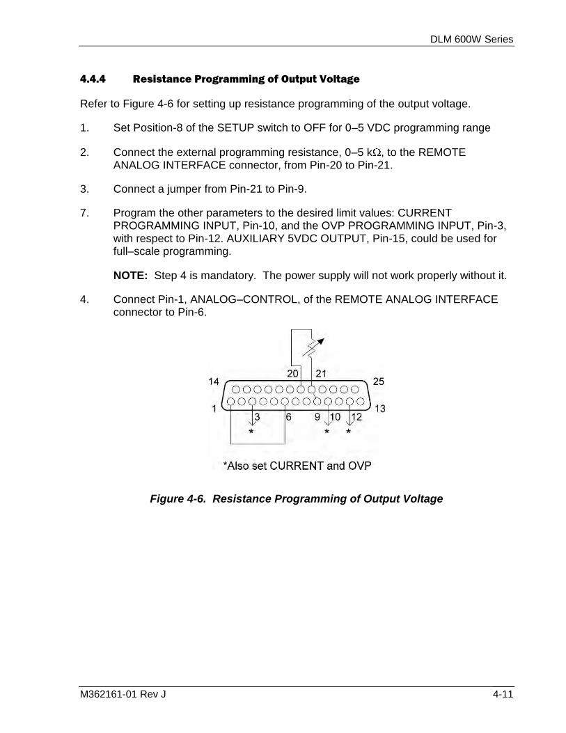
DLM 600W Series
M362161-01 Rev J 4-11
4.4.4 Resistance Programming of Output Voltage
Refer to Figure 4-6 for setting up resistance programming of the output voltage.
1. Set Position-8 of the SETUP switch to OFF for 0–5 VDC programming range
2. Connect the external programming resistance, 0–5 k , to the REMOTE ANALOG INTERFACE connector, from Pin-20 to Pin-21.
3. Connect a jumper from Pin-21 to Pin-9.
7. Program the other parameters to the desired limit values: CURRENT PROGRAMMING INPUT, Pin-10, and the OVP PROGRAMMING INPUT, Pin-3, with respect to Pin-12. AUXILIARY 5VDC OUTPUT, Pin-15, could be used for full–scale programming.
NOTE: Step 4 is mandatory. The power supply will not work properly without it.
4. Connect Pin-1, ANALOG–CONTROL, of the REMOTE ANALOG INTERFACE connector to Pin-6.
Figure 4-6. Resistance Programming of Output Voltage

DLM 600W Series
M362161-01 Rev J 4-12
4.4.5 Resistance Programming of Output Current
Refer to Figure 4-7 for resistance programming of the output current.
1. Set Position-7 of the SETUP switch to OFF for 0–5 VDC programming range.
2. Connect the external programming resistance, 0–5 k , to the REMOTE ANALOG INTERFACE connector, from Pin-23 to Pin-22.
3. Connect a jumper from Pin-22 to Pin-10.
8. Program the other parameters to the desired limit values: VOLTAGE PROGRAMMING INPUT, Pin-9, and the OVP PROGRAMMING INPUT, Pin-3, with respect to Pin-12. AUXILIARY 5VDC OUTPUT, Pin-15, could be used for full–scale programming.
NOTE: Step 4 is mandatory. The power supply will not work properly without it.
4. Connect Pin-1, ANALOG–CONTROL, of the REMOTE ANALOG INTERFACE connector to Pin-6.
Figure 4-7. Resistance Programming of Output Current

DLM 600W Series
M362161-01 Rev J 4-13
4.4.6 Resistance Programming of OVP
Refer to Figure 4-8 for setting up resistance programming of OVP.
1. Set Position-6 of the SETUP switch to OFF for 0–5 VDC programming range.
2. Connect the external resistance, 0–5 k , to the REMOTE ANALOG INTERFACE connector, from Pin-17 to Pin-16.
3. Connect a jumper from Pin-16 to Pin-3.
4. Program the other parameters to the desired limit values: VOLTAGE PROGRAMMING INPUT, Pin-9, and the CURRENT PROGRAMMING INPUT, Pin-10, with respect to Pin-12. AUXILIARY 5VDC OUTPUT, Pin-15, could be used for full–scale programming.
5. Connect Pin-1, ANALOG–CONTROL, of the REMOTE ANALOG INTERFACE connector to Pin-6.
Figure 4-8. Resistance Programming of OVP

DLM 600W Series
M362161-01 Rev J 4-14
4.5 EXTERNAL–OFF Control
The EXTERNAL–OFF control input provides the same functionality as the OUTPUT switch on the front panel. When asserted, it will turn off the output converter, discharge the output capacitors with the downprogrammer, and reset the OVP and FAULT monitors. It is opto–isolated from the other signals of the REMOTE ANALOG INTERFACE.
4.5.1 EXTERNAL–OFF with Voltage Source
EXTERNAL–OFF is asserted when a voltage within the range of 2–30 VDC is applied from Pin-14, positive, to Pin-2, return, of the REMOTE ANALOG INTERFACE connector. Refer to Figure 4-9. The voltage source and switch could be replaced with a logic gate for digital ON/OFF control.
CAUTION
The maximum float potential of either line of the EXTERNAL–OFF control signal with respect to any other signal of the REMOTE ANALOG INTERFACE is 60V(PK).
Figure 4-9. EXTERNAL–OFF with Voltage Source

DLM 600W Series
M362161-01 Rev J 4-15
4.5.2 EXTERNAL–OFF with AUXILIARY 5 VDC OUTPUT
The internal AUXILIARY 5 VDC OUTPUT of the REMOTE ANALOG INTERFACE can be used as the voltage source to drive the EXTERNAL OFF input. Because the 5 VDC source is referenced to the other signals of the analog interface, opto–isolation would be lost. The external contacts must then provide the isolation between the external control circuits and the power supply. Refer to Figure 4-10 for connection information.
Figure 4-10. EXTERNAL–OFF with AUXILIARY 5 VDC OUTPUT
4.6 Remote Monitoring
Analog signals are available for monitoring the output voltage and current. These signals vary proportionally to the output parameters, and have user selectable ranges of 0–5 VDC or 0–10 VDC for an output change from zero to full scale. Refer to Table 4–4 for information on configuring the monitors.
Monitor
Signal
REMOTE ANALOG
INTERFACE Connections SETUP Switch Signal
Range
Signal Return Position Setting
Voltage Pin-19 Pin-8 5, VMON OFF 0–5 VDC
Voltage Pin-19 Pin-8 5, VMON ON 0–10 VDC
Current Pin-7 Pin-8 4, IMON OFF 0–5 VDC
Current Pin-7 Pin-8 4, IMON ON 0–10 VDC
Table 4–4. Remote Monitoring

DLM 600W Series
M362161-01 Rev J 4-16
4.7 Remote Digital Status Signals
Digital signals are available for remote monitoring the operational status of the unit. Refer to Table 4–5 for information on the characteristics of the signals.
Status Signal
REMOTE ANALOG
INTERFACE Connections
Logic Levels (with no
signal output current) Output
Resistance Signal Return Asserted Not Asserted
VOLTAGE–MODE Pin-5 Pin-6 5V 0V 750
REMOTE–CONTROL Pin-4 Pin-6 5V 0V 750
OVP Pin-25 Pin-6 5V 0V 750
FAULT Pin-18 Pin-6 5V 0V 750
Table 4–5. Remote Digital Status Signals

M362161-01 Rev J 5-1
SECTION 5
MAINTENANCE
5.1 Introduction
This section provides information about troubleshooting, maintenance, and calibration.
5.2 Troubleshooting
If the power supply appears to be operating improperly, determine whether the power supply, load, or external control/programming circuits are the cause. Configure the unit for basic front panel controlled operation, and perform the checks of Section 3.3, Initial Functional Tests to determine if the problem is with the supply.
WARNING
POTENTIALLY LETHAL VOLTAGES EXIST IN THE POWER CIRCUITS AND THE OUTPUT OF HIGH VOLTAGE MODELS. Filter capacitors could store potentially dangerous amounts of energy for some time after power is removed. Repairs should be done only by experienced technical personnel. To prevent injury, follow the safety precautions listed in the Safety Notice at the front of this manual.
Units requiring repair during their warranty period should be returned to the manufacturer for service. Unauthorized repairs performed by anyone other than the manufacturer during the warranty period may void the warranty. Any questions regarding repair should be directed to the Service Department at 1-800-733-5427. Include the model number and the serial number in any correspondence concerning the power supply. To return a defective unit, follow the Warranty instructions (page v of this manual).
Table 5–1 presents some checks that can be performed to diagnose problems, and provides references to sections of this manual where further information is available.
SYMPTOM CHECK ACTION

DLM 600W Series
M362161-01 Rev J 5-2
SYMPTOM CHECK ACTION
No output; all displays and indicators are blank
Is the utility power present? Connect power
Is the AC input power cord defective?
Check continuity; replace if necessary
Unit starts but there is no output; OVP and FAULT indicators are off
Is the AC input voltage within the allowed range?
Connect to appropriate voltage source
Output is present momentarily but quickly shuts off; OVP and FAULT indicators are off
Does the voltage of the AC source sag when load is applied?
Ensure that the AC source has low output impedance and can supply adequate current
No output; displays and indicators are functional
Is the OVP indicator on? See Section 3.5, OVP Operation
Is the EXT–OFF indicator on? See Section 4.5, EXTERNAL–OFF Control
Is the REM indicator on? See Section 4.4, Remote Programming
Is the FAULT indicator on? Determine if an overtem-perature condition exists; allow unit to cool and then toggle the OUTPUT switch off and back on
If an overtemperature is not present, an internal fault exists
Output turns off as soon as POWER switch is turned on; OVP indicator turns on
Is remote sense selected, but sense leads are not connected?
See Section 2.10, Load Voltage Sensing
Output voltage will not adjust Is the unit in current–mode? See Section 3.4, Mode of Operation Setup
Output current will not adjust Is the unit in voltage–mode? See Section 3.4, Mode of Operation Setup
Front panel controls are nonfunctional
Is unit in remote control with LOCAL–LOCKOUT enabled?
See Section 3.6.4, LOCAL/REMOTE Switch
Front panel controls are nonfunctional; voltage display is off
Is slave mode selected? See Section 2.12, Parallel Operation
Large AC component present in output
Is the power converter unstable?
See Section 2.9.3, Noise and Impedance Effects
Table 5–1. Troubleshooting Guide

DLM 600W Series
M362161-01 Rev J 5-3
5.3 Fuse Ratings
There are no user replaceable fuses in the power supply. Internal fuses are sized for fault isolation, and, if they were open, would indicate that service is required. The internal fuses are to be checked and replaced by qualified technical personnel. Refer to Table 5–2 for a listing of the fuses.
REFERENCE DESIGNATOR FUSE RATING SIZE
F1, F2 20A, 250 VAC, Time–Delay 0.25” 1.25”
F3 6.3A, 250 VAC; Type-F; 1,500AIC 5 mm 20 mm
F4 3A, 250 VAC, Fast–Acting PWB Mounting
Table 5–2. Internal Fuses
5.4 Cleaning
Because the unit uses forced convection cooling, the air flow through the unit can pull in dust. In environments having high concentrations of dust, periodic cleaning may be required. The exterior of the unit should be cleaned with a mild solution of detergent and water. The solution should be applied onto a soft cloth, and not directly to the surface of the unit. To prevent damage to materials, do not use aromatic hydrocarbons or chlorinated solvents for cleaning.
5.5 Calibration
Calibration is easily performed, requiring only a voltmeter, DC shunt, and programming voltage source. Ensure that the accuracy of the test equipment is sufficiently better than the specifications for the parameters to be calibrated. Typically, a 6 ½ digit voltmeter is adequate for voltage measurements, and a shunt having a 0.1% tolerance for current measurements. The shunt must be sized appropriately to minimize its temperature rise, and the resultant variation of the measurement due to the shunt temperature coefficient. Also, allow the unit to warm up for 30 minutes at no load prior to performing the calibration.
WARNING
The calibration procedures are performed with the power supply top cover removed and the power on. Potentially lethal voltages exist in the power circuits and the output of high voltage models. Use insulated tools when making adjustments to circuit potentiometers, and do not touch any components or circuits.

DLM 600W Series
M362161-01 Rev J 5-4
There is some interaction of the adjustments for offset and range of the output voltage and current. Perform the offset adjustments before the range adjustments. It may take several iterations to accurately make both adjustments.
There is some variation of the output current at high current levels because of the temperature coefficient of the internal current shunts. Perform the current calibration with the power supply initially at room temperature.
Refer to Figure 5-1 for the location of test points and potentiometers on the Main PWA, and to Figure 5-2 for location of potentiometers on the Display PWA.
Figure 5-1. Main PWA Location of Test Points and Potentiometers
Figure 5-2. Display PWA Location of Potentiometers

DLM 600W Series
M362161-01 Rev J 5-5
5.5.1 Internal Reference Adjustment
Use the following procedure to adjust the internal –5.0 VDC reference:
1. Connect a voltmeter from J14-4, positive lead, to J14-6, negative lead.
2. Adjust potentiometer R379 for a reading on the voltmeter of –5.000 VDC.
5.5.2 Output Voltage Offset Adjustment
Calibration of the output voltage is done using remote control through the REMOTE ANALOG INTERFACE. Use the following procedure to adjust the output voltage offset:
1. Connect a voltmeter across the output terminals of the power supply.
2. Connect a jumper from Pin-1 to Pin-6 of the REMOTE ANALOG INTERFACE connector to enable remote control.
3. Connect jumpers from Pin-15 to Pin-10 and Pin-3 of the REMOTE ANALOG INTERFACE connector to program the output current and OVP to full scale.
4. Connect a voltage source, set to 0.050 VDC, from Pin-9 to Pin-12 of the REMOTE ANALOG INTERFACE connector.
5. Adjust potentiometer R377 on the Main PWA for a reading on the external voltmeter of 1% of full scale output voltage.
6. Iterate the output voltage offset and range adjustment until both are accurate.
5.5.3 Output Voltage Range Adjustment
Calibration of the output voltage is done using remote control through the REMOTE ANALOG INTERFACE. Use the following procedure to adjust the output voltage range:
1. Connect a voltmeter across the output terminals of the power supply.
2. Connect a jumper from Pin-1 to Pin-6 of the REMOTE ANALOG INTERFACE connector to enable remote control.
3. Connect jumpers from Pin-15 to Pin-10 and Pin-3 of the REMOTE ANALOG INTERFACE connector to program the output current and OVP to full scale.
4. Connect a voltage source, set to 5.00 VDC, from Pin-9 to Pin-12 of the REMOTE ANALOG INTERFACE connector.
5. Adjust potentiometer R378 on the Main PWA for a reading on the external voltmeter of 100% of full scale output voltage.
6. Iterate the output voltage offset and range adjustment until both are accurate.

DLM 600W Series
M362161-01 Rev J 5-6
5.5.4 Output Current Offset Adjustment
Calibration of the output current is done using remote control through the REMOTE ANALOG INTERFACE. Use the following procedure to adjust the output current offset:
1. Connect a DC shunt across the output terminals of the unit.
2. Connect a jumper from Pin-1 to Pin-6 of the REMOTE ANALOG INTERFACE connector to enable remote control.
3. Connect jumpers from Pin-15 to Pin-9 and Pin-3 of the REMOTE ANALOG INTERFACE connector to program the output voltage and OVP to full scale.
4. Connect a voltage source, set to 0.050 VDC, from Pin-10 to Pin-12 of the REMOTE ANALOG INTERFACE connector.
5. Adjust potentiometer R375 on the Main PWA for a current through the external shunt of 1% of full scale output current.
6. Iterate the output current and offset adjustments until both are accurate.
5.5.5 Output Current Range Adjustment
Calibration of the output current is done using remote control through the REMOTE ANALOG INTERFACE. Use the following procedure to adjust the output current range:
1. Connect a DC shunt across the output terminals of the unit.
2. Connect a jumper from Pin-1 to Pin-6 of the REMOTE ANALOG INTERFACE connector to enable remote control.
3. Connect jumpers from Pin-15 to Pin-9 and Pin-3 of the REMOTE ANALOG INTERFACE connector to program the output voltage and OVP to full scale.
4. Connect a voltage source, set to 5.00 VDC, from Pin-10 to Pin-12 of the REMOTE ANALOG INTERFACE connector.
5. Adjust potentiometer R376 on the Main PWA for a current through the external shunt of 100% of full scale output current.
6. Iterate the output current and offset adjustments until both are accurate.

DLM 600W Series
M362161-01 Rev J 5-7
5.5.6 Voltage Display Adjustment
Use the following procedure to calibrate the voltage display:
1. Connect a voltmeter across the output terminals of the power supply.
2. Adjust the front panel CURRENT and OVP controls to fully clockwise.
3. Turn the OUTPUT switch on.
4. Adjust the front panel VOLTAGE control for an output voltage equal to 100% of full scale.
5. Adjust potentiometer R13 on the Display PWA for a VOLTAGE display of 100% of full scale.
5.5.7 Current Display Adjustment
Use the following procedure to calibrate the current display:
1. Connect a DC shunt across the output terminals of the power supply.
2. Adjust the front panel VOLTAGE and OVP controls to fully clockwise.
3. Turn the OUTPUT switch on.
4. Adjust the front panel CURRENT control for an output current equal to 100% of full scale.
5. Adjust potentiometer R15 on the Display PWA for a CURRENT display of 100% of full scale.

DLM 600W Series
M362161-01 Rev J 5-8
This page intentionally left blank.