Embed Size (px)
Citation preview

Photochemistry and Photobiology. 1965 Vol. 4, pp. 849-868. Pergamon Press Ltd. Printed in Great Britain
SOME PROBLEMS IN THE MEASUREMENT OF RADIATION UNDER WATER : A REVIEW
D. F. WESTLAKE
River Laboratory, Freshwater Biological Association, Wareham, Dorset, England
(Received 24 June 1965)
Abstract-A brief review is given of generally agreed current practice in the terminology and methodology of radiation measurement underwater. The use of energy units is recommended for the presentation of ecological irradiance data, together with details of the spectral com- position. Absolute values may be determined above the water but relative values, determined, with selenium photocells, are more usual underwater. Some controversial or historically con? fused topics are discussed in more detail. The uses of ‘absorption’ and ‘extinction’ are critically examined. Current proposals to replace extinction by ‘attenuation’ are endorsed with the qualifications that absorption is only used when losses of radiant energy by transformation are related to path length and Bouguer-Beer constants, and that attenuation is used when losses of radiant energy are related to depth and empirical coefficients. The advantages of optical density for calculations combining and analysing the transmissions of different components of equipment or the environment are presented. Calculations for designing equipment for the analysis of spectral energy distributions and the interpretation of the results are described in detail. Use of photometers with opal discs can introduce errors when control readings on a surface cell are compared with submerged readings. The sources of these errors are described and procedures suggested to overcome them.
INTRODUCTION
MANY studies of the ecology of plants and animals require knowledge of variations in the radiation climate in space and time. Although quantitative determination often appears to be simple in principle there are many detailed practical difficulties, and comparisons are further complicated by the great confusion in the terminology of the subject. Such problems are intensified when the radiation climate under water is being studied.
Two excellent reviews, by Saut~erer(~~) and Stri~kland,@~) have recommended particular procedures and terminologies, revealing a tendency towards some standardization. How- ever there were a number of differences and confusions between Teutonic and American practice and later developments have shown further advances towards a generally agreed terminology.(29) Other useful sources of data, procedures and references are Hollaended2*) Dupr6 and Dawson(l*) and Jerlov. (2s) Prei~endorfer(~O) has discussed the application of modern radiative transfer theories to radiation under water.
This review will attempt to summarize the main agreements and will discuss four topics, which need some further clarification, in more detail:
1. The confused usage of ‘absorption’, ‘extinction’ and ‘attenuation’. 2. The uses of optical densities.
849

850 D. F. WESTLAKE
3. The calculation of the spectral distribution of visible radiant energy under water
4. The optical problems which arise when comparing readings on an aerial photo- from observations made with selective photocells and colour filters.
meter with those from an underwater photometer.
UNITS EcoIogists are normally concerned with the solar radiant energy which reaches the earth's
surface. The full spectral range is from about 300 mp (u.v.) to about 3,000 mp (i.r.), but most of the energy is within the range 400-1,000 mp. Light, radiant energy which can be detected by the human eye, extends from 380 to about 780 mp, and accounts for only about half the total. The radiation active in photosynthesis is generally taken to be between 390 and 710 mp (& 10 mp) and forms about 0.46-0.48 of the total energy.(50$ 52)
For ecological purposes the total quantity of energy received on a unit area of surface over a particular period, or the rate of incidence of energy on that surface, are usually required. This rate should be called irrczdicznce, but intensity is commonly The total irradiance, and the irradiance in selected wave-bands should be measured and expressed in terms of energy, but there has been little agreement on the units to be used. To conform with the units now favoured by physicists, based on the metre-kilogram-second system, the J/m/2 sec, or the watt per square metre (W/ma) should be Most ecologists obtain their data from meterological stations, many of which use the gram calorie per square centimetre per second (gcaI/cm2 sec), so this unit (or a related unit) is preferred by many workers.(e.g. 31* 4 4 ~ 5 0 ) The energy flow in biological communities, heat budgets and evapo-transpiration studies are usually expressed in gram calories and the gcal/cm2 min was used for the International Geophysical Year. The Iangley (I ly/min= 1 gcal/cm2 min) has been recommended,(50) but this introduces an extra word with the loss of two items of information. Table 1 summarizes the relations and inter-conversions of some of the units used.
L
TABLE 1 . CONVERSION FACTORS FOR IRRADIANCE AND ILLUMINANCE UNITS
J/mz sec ergs/cma sec lux* (mks unit) (cgs unit) gcal/cma min (illuminance. unit)
1 J/ms sec (1 w-sec/mz sec) 1 103 1 a43 x 10-3 -2*5X10B
W/mz 1 103 1.43 x 10⁻⁹ -2.5 X lot
1 gcal/cm2 min (1 ly/min) 6.98 x lo2 6,98 x lo5 1 N1.8 x 106
(1 lumen/m* or 0.0929 ft-candle) -4.0x10⁻³ -4.0 -5.7 X lo-* 1
1 lux* or m-candle
*Energy equivalents given in terms of visible radiant energy in daylight
Craig(14) has proposed that irradiance should be expressed in terms of quanta per square centimetre per second because quantitative causal descriptions of the interactions of matter and radiation can only be made in terms of the quantum theory. This is certainly

Some problems in the measurement of radiation under water: a review 851
correct and convenient for biophysicists and biochemists dealing with atomic and molecular systems (e.g., the mechanism of vision), but ecologists are concerned with the flow of relatively vast quantities of energy (e.g. the energy budget of a lake). Craig also recom- mends that colour, and analogous divisions of the electro-magnetic radiation spectrum, should be defined by the quantum energy distribution, rather than by wavelength.
It is often not satisfactory to give irradiance in terms of either total incident energy, or visible incident energy, because a large proportion of this energy may not be concerned in the response of the particular organism to be studied. The ideal solution will be to relate the irradiance to the appropriate spectral response curve and to give the result as the total effective irradiance.c29 14) This would mean that as the response is a function of the effective irradiance, the size of the response could be predicted from the irradiance whatever its ‘colour’. Until enough is known about different responses it is necessary to give the total irradiance, its spectral composition and if possible the proportions between specific wavelengths.
For many purposes it is not necessary to use absolute units when studying radiation under water because it is often sufficient, and sometimes preferable, to express the irradiance as a fraction of that received at the surface or just under the surface. Nevertheless, changes in the spectral distribution of energy may complicate or invalidate the use of the relative values observed with a photometer with selective sensitivity. The rate of incidence of light on unit area is called the izluminance or light intensity. Light from the sun, or from artificial sources with a similar spectral distribution of visible radiant energy, is seen as white by the human eye, and the photometric units of illuminance, such as the metre-candle, foot- candle, and lux (lumen per square metre), attempt to make quantitative measures of the relative illuminance by white light as detected by the average human eye. Therefore such photometric units should only be used for white or near-white light when the receptor of the organism, or the detector of the instrument, has a similar sensitivity to the human eye. Photometric units are practically meaningless for coloured light, apart from human reaction, because the relation between lux and visible incident energy changes with wavelength. Even for sources generally considered ‘white’ this relation can vary widely, and the dis- parities are even greater in terms of total radiant energy. (Table 2).
TABLE 2. APPROXIMATE ENERGY EQUIVALENTS OF 1 LUX
gcal/cmx min Light source
visible total Standard candle 2 x 10⁻⁶ - White fluorescent lamp 4 x 10⁻⁶ 5 x 10⁻⁶ Daylight 6 x 10-B 13 x Tungsten filament lamps 6-8 x lo-’ 60-80 x 10-B
Data derived from various sources.(a, 41, so, s8. 61)
To appreciate the unsuitability of photometric units for studies of the reactions of other organisms, consider a photometer reading in lux, illuminated by white light and fitted with a filter that matches the spectral response curve to the human eye. If this filter were replaced by another, so that the spectral response resembled the action curve of photo- synthesis, the reading would change. In coloured light there would be even greater differences, and the selective attenuation of water means that the illumination under water

852 D. F. WESTLAKE
soon becomes appreciably coloured. The dangers of the use of photometric units have often been pointed out (e.g. 2, ‘ 9 1 5 9 4 4 9 50), but misuse is so easy and common that the warning will bear repetition.
THE QUALITATIVE A N D QUANTITATIVE DESCRIPTION O F THE TRANSMISSION O F RADIATION THROUGH WATERS
Under strictly defined conditions, such as a beam of parallel radiation normal to a clear medium, the relations between distance, matter and radiation are easily formulated, but complications arise when more diverse situations are examined. Fortunately certain complications can be neglected in many ecological situations where sun and sky-light are to be observed.
When radiant energy passes through water the irradiance diminishes as the distance from the site of the initial measurement increases. There are three possible sources of this diminution.*
(i) Divergence When the rays from a source are not parallel the number of rays which can fall on the
detector decreases with distance as they diverge. For the limiting case of a point source, and a non-scattering, perfectly transparent medium the inverse square law describes the relation between distance and irradiance. As this loss is purely geometrical, and inter- actions with matter are not involved, situations where it is important will not be considered. In some practical situations divergence occurs but is insignificant. Consider the conical solid formed by projecting the surface joining the edges of the source and the detector. As long as this is very flat, with a very obtuse apical angle, the part of the total radiation which falls on the detector is nearly constant with changes in distance (e.g. a small detector close to a large source, or radiation from the sky). Divergence can also be neglected when the cone has a very acute apex and the changes in distance are very small compared with the distance between the source and the detector (e.g. sun-light). These will subsequently be referred to in general as ‘limiting’ situations.
(ii) Deflection This occurs when a ray ceases to follow a direct, rectilinear path, which could occur in
a region of changing refractive index, but usually happens at the surface of a suspended particle. These are called scattering particles; but scatter is usually taken to include transformation by the particles and transformation along increased path lengths (see iii). Deflection losses occur when more rays are deflected away from the detector than are deflected on to it. Deflection by itself can only decrease the irradiance observable at a given distance and does not decrease the radiant energy of individual rays. In limiting situations, described under divergence, deflection losses also become insignificant.
(iii) Transformation This is an interaction between matter and radiant energy which converts the latter into
non-radiant energy, ultimately heat. Deflected radiation may lose energy by transforma- tion by interaction with water, solutes, or the suspended, deflecting particles. Even if the
*As far as possible these terms are selected to be free from existing, and possibly confusing, optical associations.
Some problems in the measurement of radiation under water: a review 853
particles do not effect transformation, the radiant energy of a deflected ray, at a given depth, is less than the of a direct ray because the medium effects transformation throughout the longer, indirect, path.
The quantitative relations between distance, matter and irradiation depend on the nature of the radiation, the nature of the medium and the size and distance of the detector in relation to the source. The simplest relation is obtained in 'ideal' conditions, which are defined here by a parallel beam of homogenous radiant energy, normal to the plane of measurement, passing through a non-scattering medium. Homogenous energy is restricted to a single wavelength ('monochromatic'). The irradiance then diminishes according to the laws established by Bouguer (or Lambert)@l) and Beer, which have the general form il= i, (log. base)-"q (la). The initial irradiance is i, and after transmission through 1 m of the medium it becomes il. If a is a specific diminution coefficient defining the ability of unit concentration to decrease the radiant energy, then q is a quantity factor which, for solutions, is the product of concentration c and path length 1. For pure liquids the question of concentration does not arise, so that q= 1, while for solutions in which the concentration of solutes is unknown it is often convenient to find the coefficient a', which combines the specific coefficient and the concentration, so that q again equals 1 and if= i, (log. base)-"'l (lb). The logarithmic base may be 10 or e. True constant Bouguer-Beer coefficients are only obtained when the transformation of radiant energy is related to the quantity of matter encountered through the actual distances travelled. These conditions can be satisfied in pure water or aqueous solutions because the deflection losses are negligible and all radiant energy travels along direct paths between the planes of measurement. When a detector is used at a vertical distance from the initial plane (e.g. a depth of M below the water surface or the level of the initial measurement) 1 equals M ; iM= i, (log. 3 Eq. (Ib) (lc).
If the beam is not normal to the detector, and the detector is placed within the beam at each plane of measurement, 1 is the direct path length travelled between the two planes, which is greater than M. If more than one beam were used, each at a different angle of incidence, the total irradiance would be the sum of the irradiances of each beam. By finding the diminution coefficient a' of the medium under ideal conditions, and substituting this, and the total irradiances in Equation (lb) an integrated mean value of 1 could be obtained (L); Ibl==I0 (log. base) (Id). This would not be the arithmetic mean of the direct path lengths of the individual beams. If the source is heterogenous ('polychromatic') the coefficient obtained is an integrated mean value of the coefficients corresponding to the wavelengths present.
For scattering media the situation is further complicated. In non-limiting situations deflection losses will occur as well as transformation so Bouguer-Beer coefficients cannot be determined. In limiting situations the losses of deflected rays would be compensated by gains of other deflected rays, but some of these would reach the detector from below. Therefore if a sphericaI detector were used it would be possible to neglect deflection losses, but even if a plane detector were used it would often be possible to neglect deflection if great accuracy was not needed. Diminution of the radiant energy would then be a function of transformation taking place along the deflected indirect paths of the rays, both in the medium and at the surface of deflecting particles. If i, is the initial ideal irradiance in limiting situations and iG is the irradiance at a depth of M after scattering:
i$= i, (log. base) n'L (14

854 D. F. WESTLAKE
However it may not be practicable to use Bouguer-Beer coefficients because of the diffi- culties of determining the integrated mean indirect path length L (c.f. above).
Many practical problems arising in the field, or when using typical light sources, involve the measurement of natural radiation. This is diffuse and heterogenous (‘polychromatic’), and is usually subjected to scattering. It is convenient to use small letters for parallel radiation and capitals for oblique or diffuse radiation (c.f. 44). Bouguer-Beer coefficients are not normally used for natural radiation and natural waters, but natural systems behave in a mathematically analogous way when the water is homogenous, i.e. mixed. As the concentration factor is usually complex and unknown a combined coefficient E‘ is usually used :
IM = I, (log. base) - E’M
I& = I, (log. base) - E M
(24
(2b)
In these equations it is assumed that the sources of radiation are within the hemisphere above the plane of measurement and that divergence losses are not significant (limiting situations). Hence, deflection losses are insignificant. 1, is the irradiance reaching a detector at a vertical distance, or depth, M , in a non-scattering medium and I& is the same in a scattering medium. E‘ is related to depth, and is not directly related to the actual distances travelled. In theory E’ is not a true constant characteristic of the water because the values found may be influenced by the height of the sun and the angular distribution of diffused radiant energy, and hence may also vary with depth (e.g. 60). However, there arc only small effects on coefficients determined from field observations.(e.g. 3 Hutchin- son(z5) discusses this further, and it is generally found that plots of irradiance against depth in homogenous water on semi-logarithmic paper are close to straight lines, the slope of which is not dependent on the sun height. Also in theory, the slope should increase with depth, as selective absorption by the water changes the spectral distribution of the radiant energy, but this is only noticeable in the first metre where ultraviolet and infrared are removed, or in highly coloured water.(e.g. 32) When selenium photocells are used, which are most sensitive to the wavelengths most readily transmitted, this effect is generally unimportant. Changes in the slope are usually evidence that the water is not mixed.
It should be noted that the distance factors ( I and M ) , and hence the coefficients (a and E ) are now usually expressed in terms of one metre, but that many earlier tabulations by physicists used the centimetre.
When the medium is clear, the radiation is diffuse, and divergence is insignificant (cf. above), the irradiance observed at a given depth is the result of transformation along direct paths between the points at which rays cross the initial plane, and the detector. True Bouguer-Beer coefficients could only be applied by using the integrated mean direct path length (L)(js. 6 0 ) , as in Equation (Id) (above). Various determinations of the mean direct path length for natural radiation under water agree that it is about 1 -2M,(25) though the precise value varies with the height of the sun and the relative proportions of sun- and sky-light.
If scattering particles are present, in limiting situations, true Bouguer-Beer coefficients could only be applied by finding the integrated mean indirect path length, and in practice Equation (2c) is always used. A similar Equation may also be used for the ideal radiation passing through scattering media :
i& = i, (log. base) -f’M (24

Some problems in the measurement of radiation under water: a review 855
There is great confusion in the terminology of these equations, partly arising from incomplete appreciation of the processes involved and their mathematical expression. At one time the terms transmissive exponent (log. base e), transmissive index (log. base lo), or transmissive coefficient were used for diminution coefficients, (211 33) but an increase in the coefficient means a decrease in the energy transmitted.(35) The specific coefficient (a) for solutes was called the extinction coefficient. Subsequently the two terms most common- ly used and confused have been absorption and extinction. In some papers these are given mutually exclusive definitions, in others one is defined without contrast with the other, and sometimes the two are regarded as synonyms. Recently the term attenuation has been introduced.
The distinction between absorption and extinction may be defined in at least five distinct ways. It is sometimes possible to combine different ways to make further defini- tions and, for each way or combination of ways, the actual application of the two words may be reversed. In one book alone(24) the diminution of ideal radiation in solutions receives at least four different descriptions, and 'absorption' is used in at least three different contexts. It is extremely easy to make gross errors unless these possibilies are always kept in mind. Before recommending definitions for limnological purposes some of the defini- tions that have been used may be discussed. This discussion is only intended to give examples and is not a complete bibliography.
(i) According to the logarithnzic base. Stri~kland(~O) defines absorption as diminution (by transformation or deflection) expressed in terms of base e, and extinction as diminution in terms of base 10. The same distinction is often used by physicists and chemists (e.g. 8 , 22, 46, 65) .
e.g. Absorption i,= i,.e-O" (3a) Extinction ir= io.1O-"" (3b)
Absorption and extinction are both related to path length and not depth in these equations, but I = M in ideal conditions. For natural conditions, when scattered irradiance is measured by a horizontal detector looking upwards ( I s ) , Strickland uses a 'vertical' extinction coefficient, related to depth, Z:== Z,. 10-E'M
The complete reverse distinction has not been made as far as I know, but some authors (e.g. 70* 41n 49) have related absorption to the base 10 and many authors have defined extinc- tion using base e (e.g. 6* 259 30). On the other hand, numerous authors incidentally associate either absorption or extinction with one of the bases in the same way as Strickland (e.g.
The other four methods all arise from problems of applying physical principles in field conditions. Hence they are often used in combinations, and simple examples of their application are rare. This situation is fertile ground for confusion and often definitions are stated in terms of one method although examination reveals that there is an implicit combination with another method or methods.
(ii) According to the type of medium. S a ~ b e r e r ( ~ ~ ) defines absorption as the diminution of radiant energy in pure liquids or solutions, solely by transformation of the energy. Let iM, I M and ih, be irradiances detected after passage through non-scattering and scattering media, respectively. Then,
absorption is {
(3c).
1- 4, 81, 23, 61
f iM == i,, (log. base)-"'M
I I~ == I, (log.
(4a)
(4b)

8% D. F. WESTLAKE
The absorption coefficient is related to depth in both cases but for ideal radiation M = I , so true Bouguer-Beer coefficients are obtained from Equation (4a). If the natural radiation is measured by a horizontal detector directed upwards a vertical absorption coefficient is obtained. The scattering effect of water molecules is considered to be quantitatively negligible. Extinction is defined as the diminution of radiant energy in a scattering medium, by both the transformation of energy in the solution and as a consequence of scattering.
r i& = i, (log. base) - f’M
Z& = I, (log. base)-EM
(4c)
( 4 4 Extinction is {
The extinction coefficients E‘ and E’ are related to depth. If a; is the absorption coefficient of filtered water, and s’ is a scattering coefficient then E‘ = a; + s’. When these definitions are used the impression is usually given that the distinction is made entirely according to a difference in fundamental mechanism, i.e. that absorption is diminution by transformation and that extinction is diminution by both transformation and scattering. This obscures the fact that the absolute losses of radiant energy are always by transformation. Also under the limiting conditions normally prevailing for field measurements, the observed losses of radiant energy attributed to scattering are almost entirely the result of transforma- tion along increased path lengths. Deflection losses are a significant part of the observed losses only in the case of ideal radiation in non-limiting conditions.
Sauberer’s definitions were agreed at IUBS Colloquia in 1957, and essentially similar distinctions have been made elsewhere.(e.g. 3 , lo, 28, 34, 3 F 9 59) Other authors have used either absorption or extinction in ways which would not exclude Sauberer’s definition of the difference, although they do not make such a distinction. For example, Withrow and Withrow(G1) define absorption by il = i0.e-O4 (cf. Equation (4a) and S t r i ~ k l a n d ( ~ ~ ) describes vertical extinction by Equation (4d) (with log. base 10).
I have not met an example of the completely reversed distinction but absorption has been used in situations where scattered light was present, (e.g. 38, 50) and extinction has
(iii) According to the distance factor (path length OY depth): This does not occur as the sole basis of distinction but is often an implicit part of distinctions arising from the differ- ences between ideal and natural conditions. A logical derivative of Sauberer’s distinction would be to define absorption as the diminution of radiant energy, related to the integrated mean path length, and extinction as the diminution of radiant energy, related to depth when this is less than the integrated mean path length.
been used for clear solutions.(e.g. 8 , 41, 45s 46 1
Absorption is ir = i, (log. base)-” I (54 i& = i, (log. base)-A’L (5b)
Z, or Z& = Z, (log. base)-O‘l (5c)
Extinction is i& = i, (log. base)-cM ( 5 4 ZM or Z& = Z, (log. base)-E’M (53)
For ideal radiation in solutions M = I , so absorption is appropriate (Equation (5a)). With oblique, diffuse or scattered light M < L so extinction is appropriate unless L is employed. If Equation (5b) were applied in non-limiting situations, where deflection losses would be significant, the integrated mean path length would have little relevance

Some problems in the measurement of radiation under water: a review 857
and a true Bouguer-Beer coefficient would not be obtained. Such a distinction could be compatible with definitions of absorption as Equation (la), (e.g. 8* 61) some of Strickland‘s definitions(50) and the use of extinction for Equation (4d).(e.g. 3, 253
(iv) According to the nature of the radiation and according to the directionalselectivity of the detector. These could be separated but are nearly always found in combination because a spherical detector is only necessary when scattered irradiance from below is important, which arises under natural conditions. The most explicit use of these methods of distinction is to be found in Sverdrup, Johnson and Fleming,(51) where they are further implicitly combined with scattering and depth distinctions. They also call the process absorption in all circumstances and only differentiate between the absorption and extinction coeficients. The absorption coefficient is obtained with ideal radiation in clear solutions (and may be assumed to be related to path length).
Absorption is : i, = i, (log. base)“” (64
The extinction coefficient is obtained with natural radiation (subject to scattering) as measured by a horizontal detector facing upwards, and is related to depth.
Extinction is : 14 = I, (log. base)-EM (6b)
Z; is scattered irradiance as measured by such a detector. They do not indicate the terminology they would use if the scattered natural irradiance
was determined with a spherical detector (Z:). Extinction has often been specifically associated with measurements made under
natural conditions with horizontal detectors, related to depth (e.g. 3, 433 ”) and sometimes incidentally used in such circumstances.(e.g. 50) In such cases it has often had the qualifica- tion ‘vertical’. In many cases it may then be assumed that absorption could then be defined as Equation (5a). This form has often been used elsewhere for ideal conditions. (e.g. 5;3, 502 61) However, the dimunition of radiation as measured in the field has also been called vertical absorption (e.g. 4 $ 4 9 1 “) and the diminution of radiation under ideal conditions has been called extinction.(e.g. * * 2 5 7 ”)
(v) No distinction made. James and BirgecZ6) use extinction coefficient in their text in the same way as they have defined the absorption coefficient. Rabin~witch(~l) uses both terms for Equation (la) (base 10) because-‘attempts to discriminate between these two have not been successful in practice.’-Hut~hinson(~~) uses ‘extinction coefficient’ for all purposes, but also speaks of ‘absorption by natural waters’ and ‘percentile absorption’. Nydegge~(~~) restricts ‘absorption’ to transformation but uses ‘extinction coefficient’ for both clear and scattering waters.
It is clearly impossible to reconcile all these definitions, and the current trend favours avoiding the use of extinction and replacing it by attenuation.(e.g. 12, Z8)
Absorption is then defined as diminution of radiant energy with depth by transforma- tion, and attenuation as diminution with depth by absorption and scattering, which is essentially the same distinction as made in Section (ii) Equations (4a-d). The committee on Radiant Energy in the Sea, set up by the International Association of Physical Oceano- graphy, is to recommend definitions essentially of this type.(29) The distinction is adequate for general usage, but there is difficulty in applying it to the coefficients because of the ambiguity about the real mechanisms involved and the following modifications are to be preferred.
C

858 D. F. WESTLAKE
Absorption is the diminution of radiant energy with distance by transformation into non-radiant energy (Sauberer, Jerlov ; see (ii) above), related to the integrated mean path length (see (iii)). True Bouguer-Beer absorption coefficients are obtained.
ir = i,. log. baseP" (74 I , = I,. log. base-a (7c) i; = i,. log. base-'" (7b) I& = I,. log. base-a'L ( 7 4
Note that 1 = M for ideal radiation in a non-scattering medium (Equation 7a), which will be the normal application of absorption.
In Equation (7c) L is the mean integrated direct path length and in Equation (7b) and (7c) L is the integrated mean indirect path length. Absorption is only applicable to Equations (7b and d) in limiting situations (i or I ) when deflection losses are insignificant.
Attenuation (Extinction) is the experimentally observed diminution of radiant energy with depth (Sauberer, Jerlov; see (ii) above), when the integrated mean transformation path exceeds the depth (see (iii)), divergence losses are insignificant (see above) and the coefficient is related to the depth.
i$ = i,. log. I, = I,. log. (8b) I: = I,. log. base@', (8c- vertical attenuation coefficient) I; = I,. log.
(8a- beam attenuation coefficient)
(8d- global attenuation coefficient)
These equations do not cover all the possible applications but the others (e.g. ideal radiation subject to scattering in limiting situations, global detectors in non-scattering media with natural radiation) are rarely met with, or pointless, in practice. The beam attenuation coefficient (Equation (8a)) is obtained with ideal radiation in non-limiting situations (i.e. i,,). Equation (8b) also gives a vertical attenuation coefficient if determined with a horizontal detector. When the beam attenuation coefficient is analysed into an absorption coefficient and a scattering coeff i~ient(~~7~~) the absorption coefficient refers to the absorption that would be determined in water from which all the scattering particles had been removed. The scattering coefficient (integrated volume scattering function for all angles) covers transformation along increased path lengths, transformation by the particles and deflection losses.
The use of base 10 logarithms often simplifies the arithmetic (see under optical density), but definition in terms of a particular logarithm base is not recommended. The base selected must always be clearly stated.
Optical density The optical density is a useful derivative of these exponential relations between
irradiance, quantity and quality and, as it is not often discussed in biological papers, a brief account of its applications may be useful. The optical density D is the logarithm (to the base 10) of the ratio of the initial irradiance over the transmitted irradiance:
D = log. 10 (I,,/ZM) (94 In this section I , includes irradiance after scattering. The mantissa is conveniently found with a suitable slide rule by reading directly from the percentage transmission on the reciprocal scale to the logarithmic scale. It can be shown from
I , = I,.lO-ECM (9b)

Some problems in the measurement of radiation under water: a review 859
that the optical density is directly proportional to the specific attenuation coefficient, the concentration and the depth. Hence, if the optical density for unit depth or concentration is known the effect of changes in these factors can be found by simple proportion. It can also be shown that DICM = E or, with unit depth and concentration, D = E.
When a system consists of more than one component the attenuation coefficients of the individual components are additive, the total giving the attenuation coefficient of the whole system, and the same is true for the optical densities. Thus the effect of combining neutral filters, of known transmission, can be found easily.
For natural waters :
ET = Ew +- E, f E p (94
or DT = D , -t D, + Dp ( 9 4 when the sub-scripts T, w, indicate the total and the components water, solutes and suspended particles respectively. If filtered water is put in an instrument for deter- mining monochromatic beam attenuation coefficients the blank is normally distilled water so that Dw is automatically deducted, giving D,. Dp is obtained directly by using un- treated water with filtered water as a blank, or indirectly by using the pure water blank and subtracting D,. D , can be calculated from the absorption coefficient for pure water since under the conditions of the experiment, if the distilled water is pure and dust-free, D,lM = E, = a, (to base 10) (9e). Absorption coefficients for pure water have been tabulated,(26) and alternative tables and discussions of the inaccuracies in all these values may be found elsewhere.(l6? 259 51) The total optical density and the relative importance of the components can thus be found. Further details of the justification and use of basically similar calculations may be found elsewhere.(lP 25* 26* 32$ 67) A similar procedure has been used to determine the concentration of water-weed from vertical attenuation studies in weed beds.(56) ‘Optical density’ could replace ‘extinction’ as used in colouri- metric studies to refer to the diminution of radiation by coloured solutions.
and
TECHNIQUES Irradiance meters
To determine the total solar radiant energy reaching the surface of the water various instruments depending on the heating effect produced by the transformation of the energy are used. Examples in common use are the Kipp solarimeter (Kipp and Zonen, Delft, Hol- land), the Epply pyroheliometer (Epply Laboratories, Rhode Island, U.S.A.) and the Schenk Sternpyranometer (P. Schenk, Wien). The simple solarimeters recently designed by Monteith and Szeicz@l) may be adaptable for limnological and oceanographic purposes. See also Stricklandc50) who recommends the Epply instrument, S a ~ b e r e r ( ~ ~ ) who designed the Schenk instrument, and Clarke(13) who has given a general survey of radiation detectors. Sauberer has also designed a radiation balance meter. A quantum meter for aquatic applications is being developed (Steeman Nielsen, personal communication). Some instruments making absolute measurements may be used down to 5-10 m in clear water,(48) but the generally recommended procedure is to make absolute measurements above the surface and to use simpler apparatus to obtain underwater values relative to the surface values. Differences in the underwater irradiance relative to the surface are due to the properties of the water and often give more information about different waters than the absolute values which change rapidly with time and weather, and with latitude.

860 D. F. WESTLAKE
Relative readings are usually taken with selenium barrier-layer photocells, but newer types of detector are coming into use (e.g. Megatron silicon photo-voltaic cells). Calibra- tion in absolute terms is difficult because different factors are required for different sky conditions and the calibration needs frequent checking. Most selenium photocells, when mounted, have little sensitivity outside 300-700 mp and have a pronounced peak between 500 and 600 mp, hence changes in the spectral distribution of the energy will affect the readings. Such changes occur during transmission through water, particularly if this is strongly coloured. A series of colour filters should be used to reveal the extent of this effect (see below).
Spectral sensitivities and spectral energy distribution It is necessary to know the spectral selectivities of different equipment in order to make
comparisons and selections, to define their properties and to study spectral energy distri- butions under water. Sauberer recommends the use of at least three, preferably seven, colour filters or filter combinations for photosynthetically active radiation. (44) He gives details for his recommended series of Schott glass filters (Schott u. Gen., Mainz, DBR) and Lange selenium photocells (Lange, Berlin), and for definitive studies it would be best to use these. However, it is often possible to use equivalents which may be immediately available. For example, the spectral sensitivities of a range of Chance glass filters (Chance- Pilkington, St. Asaph, G.B.) and EEL photocells (Evans Electroselenium, Halstead, G.B.) are very 57) The newer interference filters have advantages for special purposes (e.g. 42) but have some disadvantages for routine use. Sauberer describes a relatively inexpensive device which will produce a smooth curve for the spectral composition of light by using an interference filter which changes in selectivity continuously along its length.
Calculations of the necessary parameters of various filter-cell combinations are not difficult in theory but are perhaps not immediately apparent and, as they have rarely been set out in detail, an account will be given here. Although direct calibration may be better(42), access to a physical laboratory is not always possible and the calculated parameters are usually adequate for field studies.
First it is necessary to prepare spectral sensitivity curves for an equal energy spectrum, that is when equal amounts of energy are received from each waveband. The basic data are usually the manufacturer’s relative sensitivity curve for the photocell (Fig. 1*, r ) and the manufacturer’s transmission data for the filters (2). If the transmission were 100 per cent and the sensitivity of the photocell were at its maximum, taken as 1, then the combined response would be 1. The sensitivity at other wavelengths is expressed relative to this response. At a given wavelength (e.g. 400 mp), where the transmission of the filter is t per cent (Fig. 1, 56 per cent) the radiant energy reaching the photocell would give a response o f t (0.56) if the cell sensitivity were at its maximum, or, when the relative cell sensitivity was r (0.62), a combined response of fr (0.35). If a combination of filters is in use, the transmission T per cent of the filter combination must be calculated first. For the greatest accuracy, especially below 400 mp and above 700 mp, it may be necessary to combine the transmissions of the glass (or perspex) window, the opal and the filters (e.g. Fig. 1, window 91 -5 per cent, opal 40 per cent, filter 56 per cent; Fig. 2, T = 20.5 per cent, Trs = 0.127) but for general purposes it may be assumed that the transmission
*Figs. 1 and 2 are given to illustrate the procedure and are not intended to be a source of accurate data.

Some problems in the measurement of radiation under water: a review 861
300 400 500 600 7 00 8 00 Wavslength rn)]
FIG. 1. Basic data for the calculation of spectral response curves for photometers. r. Rela- tive response curve for photocell (e.g. selenium cell). t. Percentage transmission of colour filter (e.g. blue filter). p. Percentage transmission of window (e.g. 2 mm Pyrex). 0. Percentage transmission of opal glass. 6. Relative energy distribution of radiation (e.g. from sun and sky).
*-
/ / 0 and <
(Half 404 -
I I 350 400
I Optical
450 500 Wavalangth rnp
Centre of gravity
444 mp Rangu 5
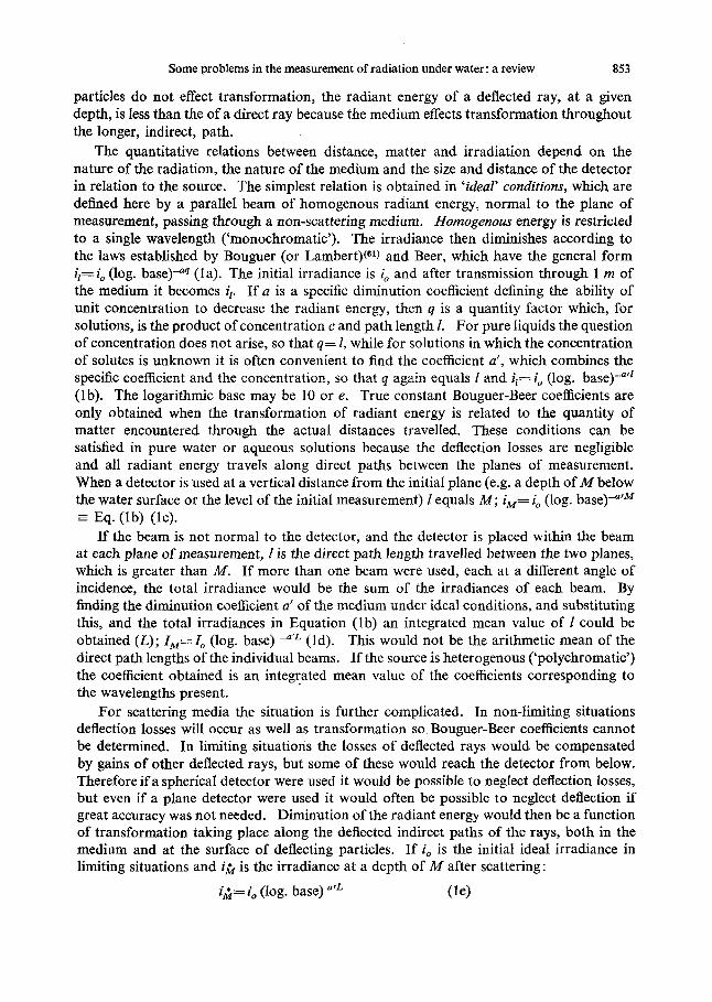
FIG. 2. Spectral response curves for typical combinations of filters with a photocell. A. Per- centage transmission of window and colour filter(s) (e.g. Pyrex window and blue ater, T%). B. Relative response of photometer with equal energy distribution in spectrum (e.g. with blue filter and selenium cell, Tr). C. Relative response of photometer with energy distribution of a typical source (e.g. blue filter in sun- and sky-light, Trb). D. Relative response of photo-
330 - 530 rnp
meter with green filter in sun and sky light.
550
8 62 D. F. WESTLAKE
of the window and opal is non-selective and can be ignored. This is repeated for enough wavelengths to allow a smooth curve to be plotted (Fig. 2,Trs).
The parameters are affected by the spectral energy distribution of the radiation, so it is now necessary to adjust the curves in relation to the type of distribution to which the equipment is to be exposed. For natural visible radiation above the water, curves may be taken from Taylor and Kerr,(53) or for artificial sources manufacturer’s data may be obtained. Such curves give the irradiance in a waveband of standard width relative to the waveband of maximum energy (Fig. 1, b) . If the relative energy of a given waveband, characterised by the central wavelength, is b (400 mp 0.58) then the final relative response is Trb (Fig. 2, 0.074).
The usual parameters are the range, the average sensitivity, the waveband width at half the maximum sensitivity, and the optical centre of gravity, which is the wavelength which divides the area under the spectral sensitivity curve in half. In practice changes in the spectral distribution of natural radiation do not affect these parameters much and it is often only necessary to use two generalised distributions, one for photometers in air and one for photometers exposed under the water being
After plotting the spectral sensitivity curves, and noting their overlap, wavelengths may be selected to divide the spectral range under study into bands corresponding to the filter. (In Fig. 2 the blue filter could be used for the waveband 380-485 mp and the green filter would be used for the next waveband.) The initial proportions of the total radiant energy in each waveband can be estimated by planimetry of the areas under a spectral distribution curve for the source, between the limiting wavelengths, and of the total area under the curve between the extreme wavelengths. The percentage transmissions deter- mined with each filter at the required depths are assumed to apply to all the radiant energy in the corresponding waveband so that if the blue filter gives a transmission of x per cent, and y per cent of the total photosynthetically available energy at the surface is in the ‘blue’ waveband, xy per cent of the total will remain at that depth. After repetition for each waveband the total may be found and the results may be expressed as percentages of the total remaining.(5. 2 7 9 449 523 561 57) Craig(14) discusses similar applications of data given in terms of quanta and electron volts.
52)
Optical problems Many optical problems arise when readings taken under water are compared with read-
ings taken above the surface because immersion alters the optical properties of the photo- meter. Two photometers that are matched in the air may cease to be matched when one is submerged.(c.f. 7* 44v “) This gives rise to various ‘surface errors’, ‘surface losses’, or ‘immersion effects’ which are often revealed by semi-logarithmic plots of uncorrected percentage transmission against depth. Even in mixed water, and after allowance has been made for surface reflection losses, the slope is different in the first 10 cm, making it appear that the vertical attenuation coefficient is different just below the surface (usually greater). Part of this may be due to the rapid extinction of the longer and shorter wavelengths so that the average vertical attenuation coefficient tends towards values corresponding to the wavelengths best transmitted. However, this effect is only important in the first few centimetres or even millimetres and when selenium photocells are used it may be scarcely noticeable as they are insensitive to the wavelengths most affected. Surface effects are still observed when colour filters are used.

Some problems in the measurement of radiation under water: a review 863
When a beam of radiant energy falls on a horizontal detector the irradiance measured decreases from a maximum, when the beam is normal to the surface, as a function of the cosine of the angle of incidence. The angular distribution of natural radiation above the water varies with the time of day, weather and shading and differs from that under water because of surface reflection, refraction and scattering. Hence, it is important that the response of the photometers must not be affected by the angle of incidence apart from the cosine relationship. A photometer covered by a clear glass window does not f a l l this requirement.('* 44p 58) The difficulty is overcome by using an opal diffusing disc as the first element in the photometers, either a glass opal level with the rim, or, better, a perspex opal partly above the rim. Then the light transmitted through the subsequent filters and windows is almost completely diffused whatever the incident light.
If the upper surface of an opal disc is ground and used dry the photometer follows the cosine relation better than a photometer with a polished opal, but if it is wetted the effect of the rough surface is largely lost. S a ~ b e r e r ( ~ ~ ) prefers to use roughened opals because it may somtimes be useful to use the surface photometer dry to obtain accurate values for low angled incident light. Otherwise he uses wetted opals on both the surface and the underwater* photometers (see below) and then it matters little whether they are rough or smooth. S t r i~k land(~~) however prefers to use the surface photometer with the opal dry at all times (see below) and he therefore recommends polished opals to avoid the differences in scattering and angular response between dry and wet ground opals.
At every interface in the system air/water-filters-cell some of the incident light will be reflected away from the photocell. These losses are mitigated to some extent because the light reflected at the lower interfaces is partially reflected back again towards the photocell at the upper interfaces. In an ideal system, where both surface and submerged photometers have the same interfaces the reflection losses are the same for both. The first step towards matching two photometers in this respect is to ensure that there is always water between the photocell windows and all the filters and opals above. This leaves the upper surface of the top opal to be matched.
The numerical values used in Fig. 3 to illustrate the following discussion are approxi- mate values for typical limnological equipment used in diffuse light. Most are based on experimental observations, or calculations from well-established optical theory, made by Berger.(9r lo) The remainder are interpolated to correspond with the known values and the mechanisms involved. The internal effects of an opal are the result of multiple scattering and reflections and no attempt is made to illustrate these in detail.
If the upper surface of an opal is covered with water less light is reflected at the water- glass transition (0.5 per cent) than at the air-glass transition (9-5 per cent). However the air-water transition reflects some light (about 7 per cent when smooth) so that the overall effect of these reflections is to increase the light entering a wet opal (+2 per cent). Inside an opal some of the back-scattered light reaching the upper surface is reflected into the opal and some emerges. The proportions depend on the limiting angle of the transition, and less emerges from the glass-air interface of a dry opal (26 -5 per cent) than from the glass- water interface of a wet opaI (41 -5 per cent), so that the light re-entering the wet opal is reduced (- 15 per cent). A small part of the increase in emergent light is due to the slight increase in light entering a wet opal (+2 per cent) and this slightly increases the emergent
*The photometer intended for use in the water will be referred to as the underwater photometer whether it is actually under the water or used above the surface. If it is necessary to stress the fact that it is being used in the water it is referred to as the submerged photometer,

864 D. F. WESTLAKE
660
Dry Opal
Ph Ot 0 m Qt Q r reading loo
WQttQd Opal
Thin water layer
100
450 Submargad Opal
Daop watar layer
78 ( - 22 X )
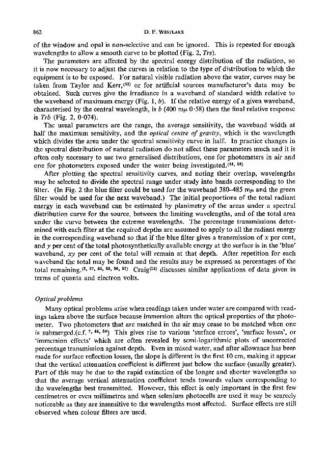
FIG. 3. Diagrams of gains and losses by photometer with opal discs in air and under water.
light travelling within the limiting angle for glass to air (to 27 per cent). The remaining emergent light (14-5 per cent) is totally reflected by the water-air tranisition. If the water layer is very thin most of this returns to the opal, where it behaves exactly as if it had been reflected and had never emerged from the upper surface. After some transformation losses (-4 per cent) the residual forward-scattered light, within the glass-water limiting angle, emerges from the lower of face of the opal (60 per cent from an opal with a dry upper-surface, 47 per cent from a deeply submerged opal). If all the light reflected at the water-air surface re-entered a wetted opal the light emerging below would be slightly greater (+13 per cent) than from an opal dry on top ($2.0 -0.5 -14.5 f14.5). In practice the readings of dry and wetted photometers are often identical (c.f. 4 3 50), so a little of the light reflected from the water-air interface must be lost before it reaches the opal (-1.5 per cent). As the depth of the water layer increases, the proportion lost increases. When a depth of 0.885 R is reached all this light misses the opal (R is the radius of the opal).
The true immersion effect, seen under a deeper water layer, is large (f2.0 -0.5 -14.5 = 13.0) and for the example given a submerged photometer reads 22 per cent less than either the dry or the wet photometer above the surface. If this change in the overall sensitivity of a photometer is Oyqrlooked there appears to be a rapid decrease in irradiance in the surface layers.

Some problems in the measurement of radiation under water: a review 865
It is impossible to match the optical properties of the surface and the submerged photo- meters by wetting the opal of the surface photometer, because of the shallow immersion effect. The final decision to use the surface photometer dry or wetted is influenced by the size of the shallow immersion effect for the particular apparatus used, the importance of low-angled light and the final treatment of the data, which accounts for differences in authors’ recommendations. As the photometer is likely to get splashed when in use, and to match the systems as far as possible it is probably best to wet the surface photo- meter for routine work. The underwater photometer can then be matched for sensitivity by wetting its opal and exposing it beside the surface photometer.
It has often been assumed that the correction factor to give submerged readings their true relation to the incident light reading is 1 .09.(41 5 0 ) In the example set out above the correction factor would be 1 *19 (neglecting attenuation the submerged irradiance would be 100 - 7 = 93 and the reading would be 100-22 = 78; 93/78 = correction factor). It is theoretically possible, using glass or perspex opals to have any value between 0.92 and 1-78. The size of the factor is a function of the refractive index and the albedo or transmission of the opal and it could be brought near to unity.(lO) The true immersion effect can be determined experimentally by using a wide blackened funnel to hold at least 0 - 9 R cm of pure water above the photometer,(lO) and under suitable conditions the reflec- tion component can be calculated from Fresnel’s law or found from tables, (e.g. “3 The correction factor can then be derived. When the shallow immersion effect is small the same correction factor can be applied whether the surface opal is used dry or wet. The influence of opal glass errors can be reduced by using optically dense neutral filters.(44)
It should be noted that surface reflection can only be studied directly with such photo- meters after the reflection has been found in known conditions. The correction factor is also essential when the surface waters are optically stratified or when underwater irradi- ances need to be accurately determined in absolute units, or relative to the surface irradiance. However, many investigations can be made without a preliminary determination of the correction factor. The attenuation coefficient is a rate constant and can be determined from the slope of semi-logarithmic plots of uncorrected readings expressed as percentages of sub-surface readings, provided that the first reading is taken deep enough for the immer- sion effect to have become constant. In mixed water this will give a straight line which can be extrapolated to zero depth where it will intersect the transmission axis below 100 per cent. This is a measure of the true immersion effect and, if this percentage is taken as the true sub-surface irradiance, percentage transmissions and optical densities of the water may be calculated.(c.f. 56) By assuming an appropriate surface reflection loss the relative surface irradiance can be calculated and hence relative or absolute underwater irradiances can be estimated from the transmission values. If a correction factor is used the extra- polation technique will give the surface reflection.
Other instruments S a ~ b e r e r , ( ~ ~ ) S t r i~kland , (~~) and Jerlov(28) discuss the design and use of transparency
or transmittance meters which are used in situ to reveal stratification of colour and turbidity and to determine beam extinction coefficients. Often it is not possible to determine these in the laboratory because of settling, the small length of spectrophotometer cells and losses of scattered energy unrelated to the path length within the water. For example, when turbid waters are studied in a ‘Unicam’ 600 spectrophotometer the optical density obtained

866 D. F. WESTLAKE
with the red sensitive photocell differs from that obtained with the blue photocell at the change-over wavelength because the energy emerging from the water has a greater distance to travel before reaching one of these photocells and thus more of the scattered energy is lost.
Transmittance meters consist essentially of a source of parallel radiation and a detector in the same mount normal to the beam at a known distance from the source. Colour filters may be inserted. Meters for the study of scattering are also discussed by Jerlov.(28)
The Secchi disc is widely used in simple studies of transparency, but if the results are to have any general significance a standard technique must be rigidly adhered to. Sa~berer(*~) and Str i~kland(~~) discuss some features of Secchi disc measurements and Sauberer makes recommendations for a standard design and procedure.
The problems of integrating irradiance over periods are often discussed (e.g. 11* 39* 47), but an ideal solution is hard to find. Planimetry of the irradiances recorded by chopper- bar instruments is tedious and not very accurate. Electronic methods, counters and electrolytic methods are often unreliable over long periods and may not respond to periods of low intensity unless amplification is used. The necessary combination of high amplifica- tion and great stability is expensive. The Siemen’s electrolytic recorder seems to be the most popular technique (e.g. 313 64) and a capacitor discharge counter has been used for underwater investigations.(l7)
Acknowledgements-The advice of Dr. R. E. Craig, Dr. B. H. Crawford and Mr. M. Owens during the preparation of this paper is much appreciated. I am particularly grateful to Dr. R. W. Preisendorfer for allowing me to see his unpublished report to the U.G.G.I. sub-committee on terms and symbols in optical oceanography, which penetrates much deeper into the fundamentals of the subject than I have attempted.
REFERENCES 1. B. ABERG and W. ROHDE, Symbolae Botan. Upsaliensis 5, (3) (1942). 2. A. ANGSTROM, Rapp. & Proc. Verb. ConseilPermanent Internat. Exploration Mer 101, ( 5 ) (1936). 3. W. R. G. A~uNS, Trans. Zllum. Eng. SOC. London, 10, l(1945). 4. W. R. G. ATKINS and H. H. POOLE, Trans. Roy. SOC. London, B, 222,129 (1933). 5. W. R. G. ATKINS and H. H. POOLE, Proc. Roy. SOC. London, B, 121,1(1936). 6. W. R. G. A~UNS, H. H. POOLE and F. J. WARREN, J. Marine Biol. Assoc. United Kingdom 28,751 (1949). 7 . W. R. G. A ~ I N S , G. L. CLARKE, H. PETTERSSON, H. H. POOLE, C. L. UTTERBACK and A. ANOSTROM,
8. J. BECQUEREL and J. ROSSIGNOL, in International Critical Tables, (E.W.WASHBURN, Ed.) 5,268. McGraw-
9. F. BERGER, Wetter u. Leben 10,164 (1958).
J. , Consiel, Permanent Internat. Exploration Mer 13,37 (1938).
Hill, N.Y. (1929).
10. F. BERGER, Arch. Meteorol. Geophys. Bioklimatol. B, 11,224 (1961). 11. G. E. BLACKMAN, J. N. BLACK and R. P. MARTIN, Ann. Botany, London 17,529 (1953). 12. W. V. BURT, J. Marine Biol. Assoc. United Kingdom 36,223 (1957). 13. F. J. J. CLARKE, Photochem. andPhotobiol. 3,91 (1964). 14. R. E. CRAIG, Photochem. andPhotobio1. 3,189 (1964). 15. B. H. CRAWFORD, News andRepts Meetings Photobiol. Grp. No. 7 , 2 (1962). 16. N. E. DORSEY, Properties of Ordinary Water Substances. Reinhold Publishing ,N.Y. (1940). 17. L. DRAPER, J. Sci. Instr. 38,474 (1961). 18. E. E. DUP& and L. H. DAWSON, US. Naval Research Lab. Bibliography No. 20. Washington, D.C.
19. C. FABRY, Rev. opt. 8,218 (1929). 20. C. S. FRENCH and V. M. K. YOUNG, in Radiation Biology, (A. HOLLAENDER, Ed.), 3, p. 343. McGraw-
21. K. S. GIBSON, J. Opt. SOC. Am. 10,169 (1925). 22. S. GLASSTONE, Textbook ofPhysica2 Chemistry (2nd ed.). Macmillan, N.Y. (1948). 23. D. HODGMAN, (Ed.), Handbook of Chemistry and Physics (36th ed.). Chemical Rubber Publishing,
(1961).
Hill, N.Y. (1956).
Cleveland, Ohio (1954).

Some problems in the measurement of radiation under water: a review 867
24. A. HOLLAENDER, (Ed.), Radiation Biol., 1-3. McGraw-Hill, N.Y. (1954,1955,1956). 25. G. E. HUTCHINSON, A Treatise on Limnology, 1. John Wiley & Sons, N.Y. (1957). 26. H. R. JAMFS and E. D. BIRGE, Trans. Wisconsin Acad. Sci. 31,l (1938). 27. P. M. JENKINS, J. Marine Btol. Assoc. United Kingdom 22,301 (1937). 28. N. G. JERMV, Oceanography and Marine Biol. 1,89 (1963). 29. N. G. JERLOV (Chairman), Union Giodks. et Giophys. Internat. Chronicle No. 57,246 (1964). 30. R. LIVINGSTON, in Radiation Biol., (A. HOLLAENDER, Ed.), 2, p. 1. McGraw-Hill, N.Y. (1955). 31. J. L. MONTEITH and G. Smrcz, Arch. Meteorol. Geophys. u. Bioklimatol. B, 11,491 (1961). 32. P. NYDEGGER, Beitr. Geol. Schweiz. Hydrol. Ser. No. 9 (1957). 33. R. H. OSTER and G. L. CLARKE, J . Opt. SOC. Am. 25,84 (1935). 34. H. P E ~ S S O N , Gfiteborge Vetensk. Vitterhets Samhall. Handl., Femte Folj. Ser. B, Matemat. Natur-
35. H. F’ETTERSSON, Bioklim. Beibl. 3, 1 (1936). 36. H. H. POOLE, Rapp. andproc. Verb. ConseilPermanenr Internat. Exploration Mer. 101, (2) (1936). 37. H. H. POOLE, Rapp andProc. Verb. ConseilPermanent Internat. Exploration Mer 108, (In, (1) (1938). 38. H. H. POOLE and W. R. G. A m s , J. Marine Biol. Assoc. United Kingdom 14,177 (1926). 39. M. C. POWELL and 0. V. S. HEATH, J. Exp. Botany 15,187 (1964). 40. R. W. PREISENDORFER, in Union Gkodks. et Gkophys. Internat. Monograph No. 10, (N. G. JERLOV, Ed.)
41. E. I. RABINOWITCH, Photosynthesis and Relatedprocesses, 2. Interscience Publishers, N.Y. (1951). 42. G. W. ROBERTSON and R. M. HOLMES, Ecology 44,419 (1963). 43. F. RUITNER, Fundamentals of Limnology (2nd ed., translated by D. G. FREY and F. E. J. FRY). Univer-
44. F. SAUBERER, Mitt. Internat. Ver. Limnol. No. 11 (1962). 45. R. L. SINSHEIMER, in Radiation Biology, (A. HOLLAENDER, Ed.), 2,165. McGraw-Hill, N.Y. (1955). 46. F. D. SNELL and C. T. SNELL, Colourimetric Methods of Analysis, vol. 1. van Nostrand, N.Y. (1948). 47. J. M. SNODGRASS, in Union Gkodis. et Giophys. Znternat. Monograph No. 10, (N . G. JERLOV, Ed.), 83
48. K. STEPHENS and J. D. H. STRICKLAND, Limnol. and Oceanograph. 7,485 (1962). 49. E. B. STEPHENSON, J. Opt. SOC. Am. 24,220 (1934). 50. J. D. H. STRICKLAND, J. Fisheries Research Board Can. 15,453 (1958). 51. H. H. SVERDRW, M. W. JOHNSON and R. H. FLEMMING, The Oceans, their Physics, Chemistry and
52. J. F. TALLING, New Phytologist, 56,29 (1957). 53. A. H. TAYLOR and G. P. KERR, J. Opt. Soc. Am. 31,3 (1941). 54. E. S. TRICKETT and L. J. MOULSLEY, J. Agr. Eng. Research 1, 1 (1956). 55. A. I. VOGEL, A Textbook of Quantitative Inorganic Analysis, (3rd ed.). Longmans, London (1961). 56. D. F. WESTLAKE, Verhandl. Internat. Ver. Limnol. 15,415 (1964). 57. D. F. WESTLAKE, in Light as an Ecological Factor, Brit. Ecol. SOC. Symposium No. 6 (G. C. EVANS and
58. L. V. W ~ Y , Trans. Wisconsin Acad. Sci. 31, 175 (1938a). 59. L. V. WHITNEY, Trans. Wisconsin Acad. Sci. 31,201 (1938b). 60. L. V. WHITNEY, J. Opt. Soc. Am. 31,714 (1941).
vetensk. Skr. 3, (8) (1934).
11 (1961).
sity of Toronto Press (1953).
(1961).
General Biology. Prentice-Hall, N.Y. (1942).
R. BAINBRIDGE, Eds). In preparation.
61. R. B. WITHROW and A. P. WITHROW, in.Radiation Biology, (A. HOLLAENDER, Ed.), 3, 125. McGraw- Hill, N.Y. (1956).
APPENDIX
Symbols and general assumptions used in section on absorption, extinction and attenuation
‘A source’ includes multiple sources if all are within the hemisphere above the plane of
Situations permitting divergence losses are not dealt with. Irradiances on different planes are measured by similar detectors. The quantitative effects of deflection in pure water are considered negligible.
measurement.
a a’ A’
specific absorption coefficient (Beer coefficient) ) Related to c in g/litre combined absorption coefficient (Bouguer coefficient) and I or L in metres a diminution coefficient for scattered ideal radiation equal to a’ except when deflec- tion losses significant (non-limiting situations), related to L (indirect path length) in metres

868 D. F. WESTLAKE
concentration of solute(s) in g/litre. log. base of natural logarithms a diminution (attenuation or extinction) coefficient for diffuse (or oblique) radiation in limiting situations, related to M in metres a diminution (attenuation or extinction) coeefficient for scattered ideal radiation related to M in metres initial irradiance from a source of parallel radiation normal to plane of measure- ment (ideal irradiance) initial irradiance as for io but in limiting situations (deflection losses could be insigni- ficant) initial irradiance as for io but in non-limiting situations (deflection losses could be significant) initially ideal irradiance after travelling I metres initially ideal irradiance, a t Mmetres initially ideal irradiance, at M metres after passing through a scattering medium (dector unspecified) initially ideal irradiance, a t M metres after passing through a scattering medium, measured with a horizontal detector initial irradiance for a diffuse (or oblique) source in limiting situations (divergence and deflection losses insignificant) diffuse irradiance, at Mmetres diffuse irradiance, at M metres, after passing through a scattering medium (detector unspecified) diffuse irradiance, a t M metres, after passing through a scattering medium, measured with a horizontal detector irradiance as IM but measured with a spherical detector
actual distance travelled by radiant energy, path length, in metres integrated mean path length for all rays (direct or indirect), in metres vertical depth or distance between planes of measurement normal to planes, in metres quantity of matter, 1 x c quantity of matter, M x c a scattering coefficient; s’ = e’-uj-’ where uj-’ is the absorption coefficient of the filtered water.
H
C
e E’
E‘
i ,
lo
I S I L M rl
Q S‘