Embed Size (px)
Citation preview
SDP TemplateTM-SPP-02 v2.0
4/05/05
SOFTWARE DEVELOPMENT PLAN TEMPLATE
TM-SPP-02 V2.0
APRIL 5, 2005
Systems Engineering Process Office, Code 20203Space and Naval Warfare Systems Center San Diego
53560 Hull Street San Diego CA 92152-5001
Approved For Public Release; Distribution Is Unlimited

SDP TemplateTM-SPP-02 v2.04/05/05
PREFACE
This document was created to provide any project developing software with a template for generating a MIL-STD 498 Data Item Description (DID) DI-IPSC-81427 compliant Software Development Plan (SDP). This template should be tailored and supplemented with project-specific information to produce an SDP that accurately describes the project’s organization, roles, and responsibilities. Space and Naval Warfare (SPAWAR) Systems Center (SSC) San Diego Software Project Planning Policy is SSC San Diego’s written organizational policy for implementing Software Project Planning (SPP) to provide management with appropriate visibility into the process being used by the software project and of the products being built.The process is intended to be an integral part of the SSC San Diego approved Life Cycle Support strategies as defined in the SSC San Diego Software Process Assets document available at http://sepo.spawar.navy.mil/. This document is intended to supplement the SPP Process by providing an SDP template that a project may use in generating its own project SDP.The SDP is the document that allows the customer insight into all stages of the software development process and addresses the commitments of the software developer to the allocated requirements. It identifies resources, estimates of size and cost, schedules, constraints, capabilities of the software developer's organization. The plan serves as a basis for managing and tracking the software activities defined to accomplish the development of the project’s software. The plan documents each group's responsibility for the development of the software.The items contained in Performing General Software Development Activities, Section 4, identify basic topics that are necessary to create a workable plan for a software project. When a significant change occurs in the approach to software development, this plan must be updated to reflect that change. In addition, an SDP should be kept current by responding to changes due to programmatic redirection.SSC San Diego’s Systems Engineering Process Office (SEPO) assumes responsibility for this document and updates it as required to meet the needs of users within SSC San Diego. SEPO welcomes and solicits feedback from users of this document so that future revisions of this document will reflect improvements, based on organizational experience and lessons learned. Users of this document may report deficiencies and or corrections using the Document Change Request that appears at the end of the document. Updates are completed in accordance with the SEPO Configuration Management Procedure.
ii
SDP TemplateTM-SPP-02 v2.0
4/05/05
RECORD OF CHANGES*A – ADDED M – MODIFIED D – DELETED
VERSIONNUMBER DATE
NUMBER OF FIGURE, TABLE OR PARAGRAPH
A*MD
TITLE OR BRIEF DESCRIPTIONCHANGEREQUESTNUMBER
1.0 10/97 Various changes resulting from Formal Inspection of this Document.
2.0 4/05/05 Throughout Various changes resulting from DCRs and extensive formatting updates
DCRs SPDT-0002 to 0007 and 0009
iii

SDP TemplateTM-SPP-02 v2.04/05/05
TEMPLATE PROTOCOL
This document provides a template for a generic Software Development Plan (SDP) that addresses the ’best practices’ described by the Software Engineering Institute (SEI) Capability Maturity Model (CMM) Version 1.1 Level 2 “Repeatable Processes,” and the guidance of MIL-STD-498. The objective is to assist organizations in documenting software development and management processes in support of the projects under their cognizance. Tailoring this template requires the author to address all requirements for the management, development, test, and coordination of those functional activities as necessary to delivering a quality product to the fleet. In addition, the generic SDP employs a tailorable software development methodology.Figure I-1 depicts the traditional practice of developing a sponsor-oriented, project-specific SDP. Often each of the SDPs describes different development methods, configuration management practices, tools; and quality assurance processes.
SDP
CMP
SQAP
SDP
CMP
SQAP
SDP
CMP
SQAP
Project AProject B
Project C
Sponsor X Sponsor Y Sponsor Z
SPONSOR DRIVEN ORGANIZATIONEACH PROJECT HAS ITS OWN UNIQUE PROCESS
SINGLE LAB ORGANIZATIONAL ENTITY
“PROJECTS TEND TO BE DISJOINT FIFEDOMS”Figure I-1. Traditional Practice
This generic SDP Template, by taking its place in the SSC San Diego Process Asset Library (PAL), will assist in providing the command a focus on a suite of standard mature processes. In addition, it will help projects meet sponsor requirements for an SDP by providing quickly tailorable engineering processes. Other templates available would include those for a Software Configuration Management Plan (SCMP) and a Software Quality Assurance Plan (SQAP). Figure I-2 reflects the change in philosophy from a federation of sponsor driven processes to one of an organization employing standard processes.
iv

SDP TemplateTM-SPP-02 v2.0
4/05/05
Figure I-2. Process Oriented Organization
Relationship to Other DocumentsThe SDP template contains software engineering process definitions and references to other key templates for software configuration management, and software quality assurance. These companion documents also comply with MIL-STD-498 and its associated DIDs. These templates comprise a suite of process descriptions that can be packaged in a multitude of formats. MIL-STD-498 was selected as it presents a widely recognized format and its guidance incorporates ‘best practices’ that are Software Engineering Institute (SEI) compliant at Capability Maturity Model for Software (SW-CMM) Level 2.
v

SDP TemplateTM-SPP-02 v2.04/05/05
DOCUMENT CONVENTIONSStandard conventions are used within this document to direct the reader to specific sections of the text. These sections provide instructions and explanations and require users to substitute their own project-specific information for the generic information provided or to “fill in the blank.” The conventions used in this document are shown below.Text Global changes. Items that appear in italics represent changes that can be
made globally throughout the document.<Text> Unique changes. Items that appear in <angled brackets> represent items that
need to be changed on an individual basis. The <angled brackets> are not meant to appear in the completed version of the document.
Italics Instructions and explanations. Each section of the template has been annotated with a guidance box, derived from the MIL-STD-498 Data Item Description (DID) DI-IPSC-81427, to assist the reader in drafting the content. For example:Guidance The guidance box provides instructions and explanations, in italics, as required to assist the user in drafting their own information.
[Sample] Text appearing between these lines is intended to provide an example of the type of
[End Sample] content expected in the section in which it appears.The samples have been constructed such that if extracted from the template with their associate paragraph number they would create a good first draft of an SDP based on the sound software engineering practices of MIL-STD 498. Combining the DID derived guidance with sample content has created a template in the form of an annotated version of the SDP DID.Users should first review the generic processes contained in the SDP to ensure an understanding of scope, software engineering processes, management functions, relationships, and responsibilities for the positions within the model organization. For example, the samples address processes for the positional roles contained in Section 7.1 of the SDP template. A table is included in Section 7.1 as a Note to help define the roles in the model organization. It is important to understand that the sample organization and processes do not fit all projects but serve as a representative example, requiring tailoring to meet project specific needs.It is recommended that the Section 7.1 organizational diagram and table be printed and kept readily available for reference as one reads the individual samples associated with the guidance information. The model organization and the processes contained in the template reflect a software project that is but one of several projects assigned to a Division. The sample project is tasked to develop software; integrate it into its target hardware environment; support the software through the sponsor’s acceptance testing; and provide distribution, field support, and follow-on maintenance. It is also assumed that the Project Manager has established and placed in operation a System Configuration Control Board (SCCB).The SDP begins on the next page with a SDP title and approval page. Delete this Document Conventions page and all preceding pages in the final version of your PMP. Remember to update the header to reflect the appropriate document identifier for your project’s SDP.
vi

Project Name SDP Document Identifier
Date
SOFTWARE DEVELOPMENT PLAN
FOR THE
PROJECT NAME
DOCUMENT IDENTIFIER
DATE
Prepared For:
Prepared By:
Code Name, Code ####Space and Naval Warfare Systems Center San Diego
Street AddressSan Diego, CA 92152-####
Approved for public release; distribution is unlimited

Project Name SDP Document IdentifierDate
This page intentionally left blank.
ii

Project Name SDP Document Identifier
Date
SOFTWARE DEVELOPMENT PLAN
FOR THE
PROJECT NAME
DOCUMENT IDENTIFIER
DATE
Prepared By:
Code Name, Code ####Space and Naval Warfare Systems Center San Diego
Street AddressSan Diego, CA 92152-####
Software Project Manager Program Manager Senior Manager
Configuration Management Quality Assurance Hardware Manager
Systems Engineer Integrated Logistics Support Test Manager
IV&V Activity Facilities Manager Other Affected Groups
iii

Project Name SDP Document IdentifierDate
PREFACE
<Provide appropriate preface to introduce this document>
iv

Project Name SDP Document Identifier
Date
RECORD OF CHANGES*A - ADDED M - MODIFIED D - DELETED
VERSIONNUMBER DATE
NUMBER OF FIGURE, TABLE OR PARAGRAPH
A*MD
TITLE OR BRIEF DESCRIPTIONCHANGEREQUESTNUMBER
v

Project Name SDP Document IdentifierDate
TABLE OF CONTENTSSection Page
SECTION 1. SCOPE............................................................................................................... 1-4
1.1 IDENTIFICATION.................................................................................................... 1-41.2 SYSTEM OVERVIEW.............................................................................................. 1-41.3 DOCUMENT OVERVIEW........................................................................................ 1-41.4 RELATIONSHIP TO OTHER PLANS......................................................................1-4
SECTION 2. REFERENCED DOCUMENTS.........................................................................2-4
SECTION 3. OVERVIEW OF REQUIRED WORK...............................................................3-4
SECTION 4. PLANS FOR PERFORMING GENERAL SOFTWARE DEVELOPMENT ACTIVITIES............................................................................................................................ 4-4
4.1 SOFTWARE DEVELOPMENT PROCESS...............................................................4-44.2 GENERAL PLANS FOR SOFTWARE DEVELOPMENT........................................4-4
4.2.1 Software Development Methods..........................................................................4-44.2.2 Standards for Software Products..........................................................................4-44.2.3 Reusable Software Products................................................................................4-44.2.4 Handling of Critical Requirements......................................................................4-44.2.5 Computer Hardware Resource Utilization...........................................................4-44.2.6 Recording of Rationale........................................................................................ 4-44.2.7 Access for Acquirer Review................................................................................4-4
SECTION 5. PLANS FOR PERFORMING DETAILED SOFTWARE DEVELOPMENT ACTIVITIES............................................................................................................................ 5-4
5.1 PROJECT PLANNING AND OVERSIGHT..............................................................5-45.1.1 Software Development Planning.........................................................................5-45.1.2 CSCI Test Planning............................................................................................. 5-45.1.3 System Test Planning.......................................................................................... 5-45.1.4 Software Installation Planning.............................................................................5-45.1.5 Software Transition Planning..............................................................................5-45.1.6 Following and Updating Plans, including Intervals for Management Review......5-4
5.2 ESTABLISHING A SOFTWARE DEVELOPMENT ENVIRONMENT..................5-45.2.1 Software Engineering Environment.....................................................................5-45.2.2 Software Test Environment.................................................................................5-45.2.3 Software Development Library...........................................................................5-45.2.4 Software Development Files................................................................................5-45.2.5 Non-Deliverable Software...................................................................................5-4
5.3 SYSTEM REQUIREMENTS ANALYSIS.................................................................5-45.3.1 Analysis of User Input......................................................................................... 5-45.3.2 Operational Concept............................................................................................ 5-45.3.3 System Requirements.......................................................................................... 5-4
vi

Project Name SDP Document Identifier
Date
5.4 SYSTEM DESIGN..................................................................................................... 5-45.4.1 System-Wide Design Decisions...........................................................................5-45.4.2 System Architectural Design...............................................................................5-4
5.5 SOFTWARE REQUIREMENTS ANALYSIS...........................................................5-45.5.1 Software Requirements Development Process.....................................................5-4
5.6 SOFTWARE DESIGN............................................................................................... 5-45.6.1 CSCI-Wide Design Decisions..............................................................................5-45.6.2 CSCI Architectural Design..................................................................................5-45.6.3 CSCI Detailed Design.........................................................................................5-4
5.7 SOFTWARE IMPLEMENTATION AND UNIT TESTING.....................................5-45.7.1 Software Implementation....................................................................................5-45.7.2 Unit Testing........................................................................................................ 5-45.7.3 Test Case/Procedure Implementation...................................................................5-4
5.8 UNIT INTEGRATION AND TESTING....................................................................5-45.8.1 Purpose................................................................................................................ 5-45.8.2 Roles and Responsibilities...................................................................................5-45.8.3 Entry Criteria...................................................................................................... 5-45.8.4 Inputs.................................................................................................................. 5-45.8.5 Process Activities................................................................................................5-45.8.6 Outputs................................................................................................................ 5-45.8.7 Exit Criteria......................................................................................................... 5-45.8.8 Process Measurements......................................................................................... 5-4
5.9 CSCI QUALIFICATION TESTING..........................................................................5-45.9.1 Independence in CSCI Qualification Testing.......................................................5-45.9.2 Testing on the Target Computer System..............................................................5-45.9.3 Performing CSCI Qualification testing................................................................5-4
5.10 CSCI/HWCI INTEGRATION AND TESTING.........................................................5-45.10.1 Preparing for CSCI/HWCI Integration and Testing.............................................5-45.10.2 Performing CSCI/HWCI Integration and Testing................................................5-45.10.3 Revision and Retesting........................................................................................5-45.10.4 Analyzing and Recording CSCI/HWCI Integration and Test Results...................5-4
5.11 SYSTEM QUALIFICATION TESTING...................................................................5-45.11.1 Independence in System Qualification Testing....................................................5-45.11.2 Testing on the Target Computer System..............................................................5-45.11.3 Preparing for System Qualification Testing.........................................................5-45.11.4 Dry Run of System Qualification Testing............................................................5-45.11.5 Performing System Qualification Testing............................................................5-45.11.6 Revision and Retesting........................................................................................5-45.11.7 Analyzing and Recording System Qualification Test Results..............................5-4
5.12 PREPARING FOR SOFTWARE USE.......................................................................5-45.12.1 Preparing the Executable Software......................................................................5-45.12.2 Preparing Version Descriptions for User Sites.....................................................5-45.12.3 Preparing User Manuals......................................................................................5-45.12.4 Installation at User Sites......................................................................................5-4
5.13 PREPARING FOR SOFTWARE TRANSITION.......................................................5-4
vii

Project Name SDP Document IdentifierDate
5.14 SOFTWARE CONFIGURATION MANAGEMENT................................................5-45.15 SOFTWARE PRODUCT EVALUATION.................................................................5-45.16 SOFTWARE QUALITY ASSURANCE....................................................................5-45.17 CORRECTIVE ACTION...........................................................................................5-45.18 JOINT TECHNICAL AND MANAGEMENT REVIEWS.........................................5-4
5.18.1 Joint Technical Reviews......................................................................................5-45.18.2 Joint Management Reviews.................................................................................5-4
5.19 OTHER SOFTWARE DEVELOPMENT ACTIVITIES............................................5-45.19.1 Risk Management................................................................................................ 5-45.19.2 Software Management Indicators........................................................................5-45.19.3 Security and Privacy............................................................................................ 5-45.19.4 Subcontractor Management.................................................................................5-45.19.5 Interface With Software Independent Verification and Validation (IV&V) Agents
5-45.19.6 Coordination With Associate Developers............................................................5-45.19.7 Improvement of Project Processes.......................................................................5-4
SECTION 6. SCHEDULES AND ACTIVITY NETWORK...................................................6-4
SECTION 7. PROJECT ORGANIZATION AND RESOURCES...........................................7-4
7.1 PROJECT ORGANIZATION....................................................................................7-47.2 PROJECT RESOURCES...........................................................................................7-4
SECTION 8. NOTES.............................................................................................................. 8-4
8.1 ACRONYMS............................................................................................................. 8-4
APPENDIX A. Project Plan.................................................................................................... A-4
LIST OF FIGURESFigure Page
Figure 1-1. RBC System Software Overview...........................................................................1-4Figure 4-1. XY Project Software Engineering Process Model..................................................4-4Figure 4-2. Test Roles and Responsibilities.............................................................................4-4Figure 5-1 Project Planning and Oversight Process..................................................................5-4Figure 6-1. Master Build Schedule..........................................................................................6-4Figure 7-1. XY Project Organizational Structure......................................................................7-4
LIST OF TABLESTable Page
Table 3-1. Key Features of Three DoD Program Strategies.....................................................3-4Table 4-1. Development Activities Group Allocation..............................................................4-4Table 4-2. Standards and Specifications Applicable to Software Development........................4-4
viii

Project Name SDP Document Identifier
Date
Table 5-1. The XY Project SEE Tools.....................................................................................5-4Table 5-2. Software Test Environment....................................................................................5-4Table 5-3. XY Project's Non Deliverable Software..................................................................5-4Table 7-1. Roles and Responsibilities......................................................................................7-4Table 7-2. Personnel Requirements (Person yrs)......................................................................7-4
ix

Project Name SDP Document Identifier
Date
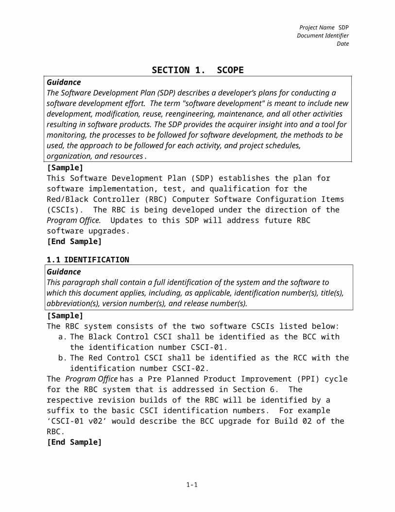
SECTION 1. SCOPEGuidanceThe Software Development Plan (SDP) describes a developer’s plans for conducting a software development effort. The term "software development" is meant to include new development, modification, reuse, reengineering, maintenance, and all other activities resulting in software products. The SDP provides the acquirer insight into and a tool for monitoring, the processes to be followed for software development, the methods to be used, the approach to be followed for each activity, and project schedules, organization, and resources.[Sample]This Software Development Plan (SDP) establishes the plan for software implementation, test, and qualification for the Red/Black Controller (RBC) Computer Software Configuration Items (CSCIs). The RBC is being developed under the direction of the Program Office. Updates to this SDP will address future RBC software upgrades.[End Sample]
1.1 IDENTIFICATIONGuidanceThis paragraph shall contain a full identification of the system and the software to which this document applies, including, as applicable, identification number(s), title(s), abbreviation(s), version number(s), and release number(s).[Sample]The RBC system consists of the two software CSCIs listed below:
a. The Black Control CSCI shall be identified as the BCC with the identification number CSCI-01.
b. The Red Control CSCI shall be identified as the RCC with the identification number CSCI-02.
The Program Office has a Pre Planned Product Improvement (PPI) cycle for the RBC system that is addressed in Section 6. The respective revision builds of the RBC will be identified by a suffix to the basic CSCI identification numbers. For example ‘CSCI-01 v02’ would describe the BCC upgrade for Build 02 of the RBC. [End Sample]
1.2 SYSTEM OVERVIEWGuidanceThis paragraph shall briefly state the purpose of the system and the software to which this document applies. It shall describe the general nature of the system and software; summarize the history of system development, operation, and maintenance; identify the project sponsor, acquirer, user, developer, and support agencies; identify current and planned operating sites; and list other relevant documents. [Sample]The XY Project involves the development and upgrade for the software of the Red/Black Controller (RBC), a multipurpose cryptographic system hosted in a desktop configuration. RBC provides the requisite communications security for systems and equipment implementing a
1-1

Project Name SDP Document IdentifierDate
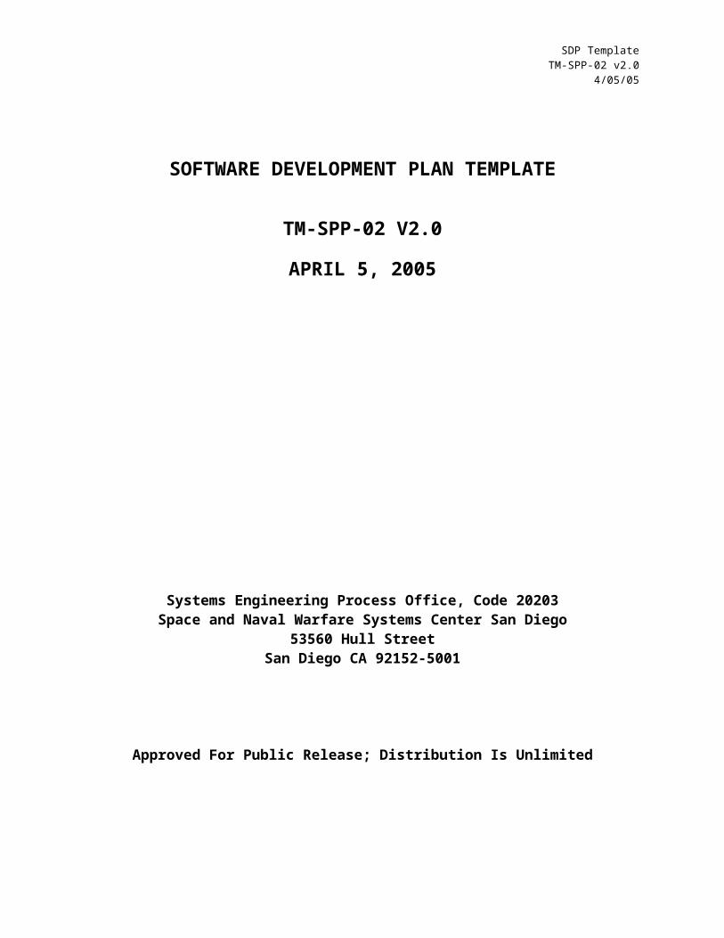
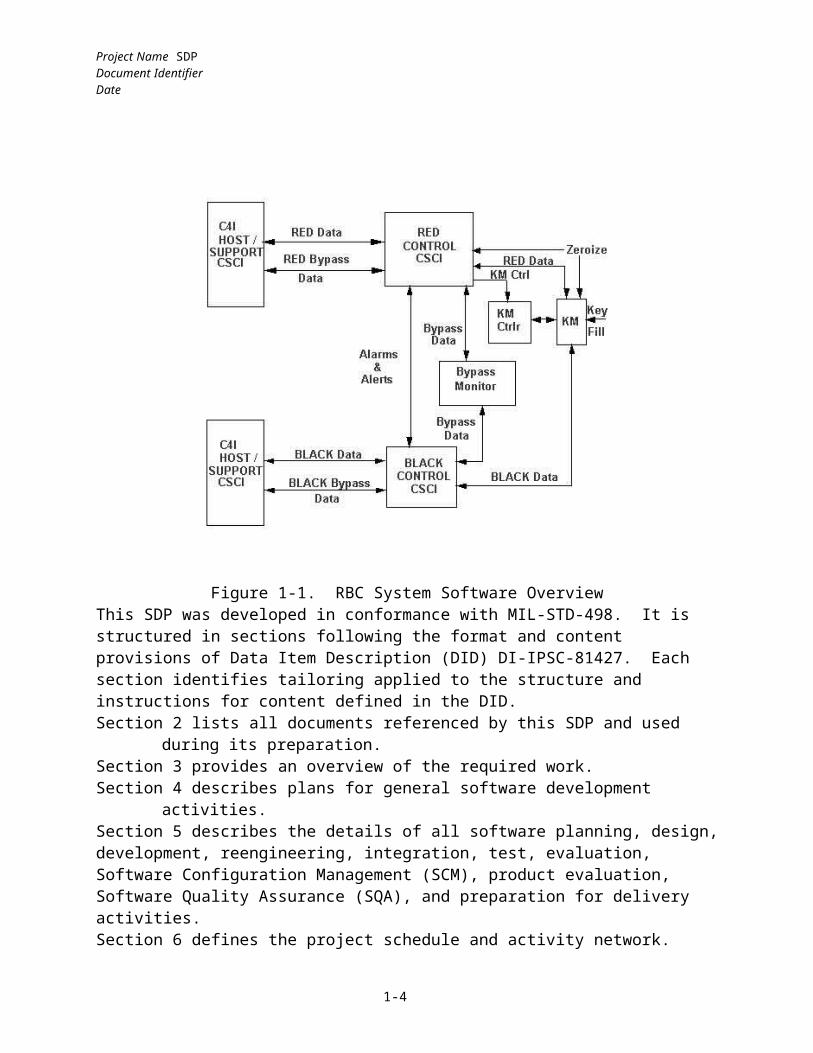
wireless communication networks. The RBC provides encryption/decryption services for numerous applications as part of communications systems, subsystems, and networks. The RBC can be applied at either the subscriber level (to provide isolation between users of the network at different clearance levels or differing need-to-know requirements) and at the link level (to provide encryption/decryption of all network control information and secondary encryption/decryption of all user data). The RBC does not operate in a stand-alone setting, but as a component in an overall Command, Control, Communications, Computation and Intelligence (C4I) system.The RBC consists of two interfacing hardware configuration items embedded in the host C4I system. The software consists of the Red Control CSCI (RCC) and Black Control CSCI (BCC) residing in a RED and a BLACK Wintel processor components of the host C4I system. The purpose of the BCC is to handle the BLACK data and BLACK control interfaces, handle the RCC interface, perform BLACK bypass data filtering and control, and conduct self test. The purpose of the RCC is to handle the RED control interfaces, handle the BCC interface, control the Cryptographic Module (KM), perform security management, perform Alarm/Alert processing, perform RED bypass data filtering and control, and conduct self test. Figure 1-1 is an overview of the RBC system and its hosted software CSCIs. [End Sample]
1.3 DOCUMENT OVERVIEWGuidanceThis paragraph summarizes the purpose and contents of this document. The purpose is usually short enough for one paragraph of one to four sentences. The contents of the various sections of this document are listed below:
a. Section 2 lists all the documents used as references during the preparation of this document as well as all documents referenced herein.
b. Section 3 enumerates the requirements that need to be imposed on developers for this plan to succeed.
c. Section 4 outlines the plans, methods, and processes to be employed by the Re-Engineering effort.
d. Section 5 provides the detail on the complete spectrum of software engineering activities being employed.
[Sample]This SDP identifies applicable policies, requirements, and standards for XY Project software development. It defines schedules, organization, resources, and processes to be followed for all software activities necessary to accomplish the development. This SDP contains no privacy considerations pertaining to the XY Project.
1-2

Project Name SDP Document Identifier
Date
Figure 1-1. RBC System Software OverviewThis SDP was developed in conformance with MIL-STD-498. It is structured in sections following the format and content provisions of Data Item Description (DID) DI-IPSC-81427. Each section identifies tailoring applied to the structure and instructions for content defined in the DID.Section 2 lists all documents referenced by this SDP and used during its preparation.Section 3 provides an overview of the required work.Section 4 describes plans for general software development activities.Section 5 describes the details of all software planning, design, development, reengineering, integration, test, evaluation, Software Configuration Management (SCM), product evaluation, Software Quality Assurance (SQA), and preparation for delivery activities.Section 6 defines the project schedule and activity network.Section 7 describes the project organization and the resources required to accomplish the work.Section 8 contains the acronyms used in this SDP.Appendices contains the MicroSoft Project plan (Appendix A), coding standards, and other
pertinent forms and data.[End Sample]
1.4 RELATIONSHIP TO OTHER PLANSGuidance
1-3

Project Name SDP Document IdentifierDate
This paragraph shall describe the relationship, if any; of the SDP to other project management plans.[Sample]This SDP and its companion documents, the Software Configuration Management Plan (SCMP), and the Software Quality Assurance Plan (SQAP), serve as the guiding documents to develop the software for the XY Project.[End Sample]
1-4
Project Name SDP Document Identifier
Date
SECTION 2. REFERENCED DOCUMENTS
GuidanceThis section shall list the number, title, revision, and date of all documents referenced in this plan. This section shall also identify the source for all documents not available through normal Government stocking activities.[Sample]The documents listed below were either used to create this document or are referenced in it:
a. Software Development and Documentation, MIL-STD-498b. Technical Reviews and Audits for Systems, Equipment, and Computer Software, MIL-
STD-1521c. Software Development Plan, Data Item Description DI-IPSC-81427d. Software Project Planning Process, SSC San Diegoe. Software Development Plan Template, SSC San Diegof. XY Project Software Configuration Management Plang. XY Project Software Quality Assurance Planh. XY Project Software Measurement Plani. Risk Management Process, SSC San Diegoj. A Description of the SSC San Diego Software Process Assets (SPA), SEPO, dated April
2001. See http://sepo.spawar.navy.mil/k. SSC San Diego COTS Evaluation, Selection and Qualification Processl. Institute of Electrical and Electronics Engineers (IEEE)/Electronic Industries Association
(EIA) 12207 Series, IEEE and EIA, March 1998m. Etc.
[End Sample]
2-1

Project Name SDP Document IdentifierDate
This page intentionally left blank.
2-2

Project Name SDP Document Identifier
Date
SECTION 3. OVERVIEW OF REQUIRED WORK
GuidanceThis section shall be divided into paragraphs as needed to establish the context for the planning described in later sections. It shall include, as applicable the items listed below:
a. Requirements and constraints on the system and software to be developed.b. Requirements and constraints on project documentation.c. Position of the project in the system life cycle.d. The selected program/acquisition strategy or any requirements or constraints on it. The
three basic strategies are summarized below and in Table 3-1. 1. Grand design. The "grand design" strategy (not named in DODI 5000.2 but treated
as one strategy) is essentially a "once-through, do-each-step-once" strategy. Simplistically: determine user needs, define requirements, design the system, implement the system, test, fix, and deliver.
2. Incremental. The "incremental" strategy (called "Preplanned Product Improvement" in DODI 5000.2) determines user needs and defines the system requirements, then performs the rest of the development in a sequence of builds. The first build incorporates part of the planned capabilities, the next build adds more capabilities, and so on, until the system is complete.
3. Evolutionary. The "evolutionary" strategy also develops a system in builds, but differs from the incremental strategy in acknowledging that the user need is not fully understood and all requirements cannot be defined up front. In this strategy, user needs and system requirements are partially defined up front, then are refined in each succeeding build.
e. Requirements and constraints on project schedules and resources.f. Other requirements and constraints, such as project security, privacy, methods,
standards, and interdependencies in hardware and software development.
TABLE 3-1. KEY FEATURES OF THREE DOD PROGRAM STRATEGIES
Program Strategy Define All Requirements First?
Multiple Development
Cycles?Field Interim
Software?
Grand Design Yes No NoIncremental (Preplanned Product Improvement) Yes Yes Maybe
Evolutionary No Yes Yes
[Sample]The XY Project will apply an Incremental (Preplanned Product Improvement) strategy to develop and evolve the functional capabilities of the RBC System Software. The RBC System Software requirements are controlled by the Program Manager’s System Configuration Control Board (SCCB). All issues concerning cost, schedule, and incremental build content must be negotiated with the SCCB.
3-1
Project Name SDP Document IdentifierDate
[End Sample]
3-2
Project Name SDP Document Identifier
Date
SECTION 4. PLANS FOR PERFORMING GENERAL SOFTWARE DEVELOPMENT ACTIVITIES
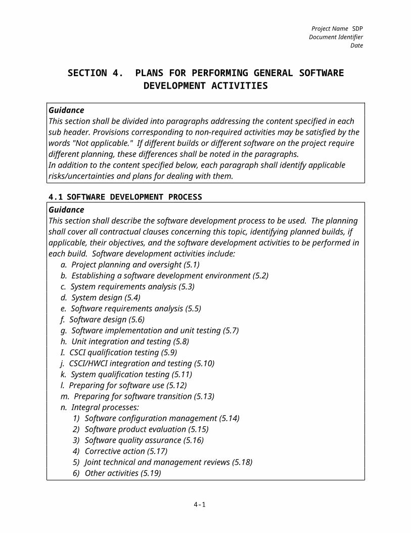
GuidanceThis section shall be divided into paragraphs addressing the content specified in each sub header. Provisions corresponding to non-required activities may be satisfied by the words "Not applicable." If different builds or different software on the project require different planning, these differences shall be noted in the paragraphs.In addition to the content specified below, each paragraph shall identify applicable risks/uncertainties and plans for dealing with them.
4.1 SOFTWARE DEVELOPMENT PROCESSGuidanceThis section shall describe the software development process to be used. The planning shall cover all contractual clauses concerning this topic, identifying planned builds, if applicable, their objectives, and the software development activities to be performed in each build. Software development activities include:
a. Project planning and oversight (5.1)b. Establishing a software development environment (5.2)c. System requirements analysis (5.3)d. System design (5.4)e. Software requirements analysis (5.5)f. Software design (5.6)g. Software implementation and unit testing (5.7)h. Unit integration and testing (5.8)I. CSCI qualification testing (5.9)j. CSCI/HWCI integration and testing (5.10)k. System qualification testing (5.11)l. Preparing for software use (5.12)m. Preparing for software transition (5.13)n. Integral processes:
1) Software configuration management (5.14)2) Software product evaluation (5.15)3) Software quality assurance (5.16)4) Corrective action (5.17)5) Joint technical and management reviews (5.18)6) Other activities (5.19)
[Sample]The MIL-STD 498 Incremental Life Cycle Model and the DID for the SDP have been used to guide the content and format developing the SDP. Overall, IEEE/EIA 12207 Supporting Processes and Organizational Process have been applied in to the management and control of the XY Project The integration of the MIL-STD 498’s Incremental Life Cycle Model into the
4-1

Project Name SDP Document IdentifierDate
context of IEEE/EIA 12207 disciplines is illustrated in Figure 4-1. Section 5 contains the specifics of the XY Project’s implementation of the processes in Figure 4-1The allocation of functional requirements for each build will be negotiated with the Program Manager’s System Configuration Control Board (SCCB) and documented in the Build Plan for each build. The Build Plan will also include build specific acceptance criteria and installation/user training requirements. The process will integrate reusable software from existing sources with newly-developed software. Software design and coding will be performed by the Software Development Group using an object oriented design approach and generate class and object process interaction diagrams. Artifacts and evidence of results of software development activities will be deposited in Software Development Files (SDFs) and Software Engineering Notebooks (SENs). These artifacts, along with pertinent project references will be deposited and maintained in a Software Development Library (SDL) and made available to support management reviews, metrics calculations, quality audits, product evaluations, and preparation of product deliverables.Following integration of reusable and new software units by the Software Test and Evaluation Group, a software Formal Qualification Testing (FQT) will be performed in accordance with processes defined in Section 5. A Test Readiness Review (TRR) will be conducted to verify readiness for system level testing. The System Test Organization will prepare a Test Plan (TP) for a system level FQT and execute test cases defined in the implementing Test Description (TD). They will generate Problem/Change Reports (P/CRs) to describe software errors uncovered during test results analyses. The System Test Organization will be supported by the XY Project , providing analysis and repair as required. The separation of organizational entities and their testing responsibilities is illustrated in Figure 4-2.Software Configuration Management (SCM), Software Quality Assurance (SQA), and Software Product Evaluation, Corrective Action, and preparation for software delivery will follow detailed processes described in Section 5 of this SDP.
4-2
Project Name SDP Document Identifier
Date
Figure 4-1. XY Project Software Engineering Process Model
Figure 4-2. Test Roles and Responsibilities[End Sample]
4-3

Project Name SDP Document IdentifierDate
4.2 GENERAL PLANS FOR SOFTWARE DEVELOPMENT[Sample]XY Project software development will conform to MIL-STD-498. The development approach will be to apply SSC San Diego standard management and technical work processes to the project. The SSC San Diego standard work processes are defined in reference (g), A Description of the SSC San Diego Software Process Assets (SPA). The project team has tailored these standards, practices, and processes to XY Project software development, as described in Section 5 of this SDP. [End Sample]4.2.1 Software Development MethodsGuidanceThis paragraph shall describe or reference the software development methods to be used. Included shall be descriptions of the manual and automated tools and procedures to be used in support of these methods. The methods shall cover all contractual clauses concerning this topic. Reference may be made to other paragraphs in this plan if the methods are better described in context with the activities to which they will be applied.[Sample]The XY Project software development will apply the following general methods:
a. The project will follow the defined processes documented in Section 5 to conduct software requirements analysis and manage the Software Requirements Specification (SRS). Express software requirements in language that addresses a single performance objective per statement and promotes measurable verification. Construct a software architecture that will consist of reusable software components and components to be developed. Allocate software requirements to one or more components of that architecture. Use an automated data base tool to capture, cross-reference, trace, and document requirements.
b. The Software Development Group and the Software Test and Evaluation Group collaborate during software requirements analysis and then each proceed with separate activities that are intended to ensure the software complies with the detailed software requirement specification. These activities for the Software Development Group and the Software Test and Evaluation Group are defined in Table 4-1. The activities for each group will be addressed separately in Section 5.
TABLE 4-1. DEVELOPMENT ACTIVITIES GROUP ALLOCATION
c. The project will only design and develop software to meet requirements that cannot be satisfied by reusable software. New software will be based on principles of object-oriented design and exploit object-oriented features associated with the selected high-level language and development environment. New software design will be defined at
4-4

Project Name SDP Document Identifier
Date
top-level and detailed design stages of development in the SDD. Software design will promote ease of future growth, specifically new application interfaces. Top-level design will be expressed in a graphical form. Detailed design will also be expressed in a graphical form depicting classes, relationships, operations, and attributes.
d. The project will adhere to the standards required by the SDP for design, coding, and test methods for new software.
e. The project will reuse software for requirements that can be satisfied by selected Non-Development Item (NDI) software. Selection of NDI products shall follow the process and procedures as defined in reference (h), the SSC San Diego COTS Evaluation, Selection and Qualification Process.
f. The project will modify (as necessary), unit test, integrate, and document reused software following the same processes used for new software. While reused code will not be expected to conform to a single coding standard, changed source code must be supplemented with sufficient new comments and standard code headers to meet commenting provisions of the coding standard and to promote understandability
[End Sample]4.2.2 Standards for Software ProductsGuidanceThis paragraph shall describe or reference the standards to be followed for representing requirements, design, code, test cases, test procedures, and test results. The standards shall cover all contractual clauses concerning this topic. Reference may be made to other paragraphs in this plan if the standards are better described in context with the activities to which they will be applied. Standards for code shall be provided for each programming language to be used. [Sample]XY Project software development will comply with applicable directions contained in the documents listed in Table 4-2. These documents impose standards that are applicable to software requirements, design, coding, testing, and data.
TABLE 4-2. STANDARDS AND SPECIFICATIONS APPLICABLE TO SOFTWARE DEVELOPMENT
Document Description<Fill in project specifics>
<Project program coding standards are a good example.>
MIL-STD-498 Software Development and Documentation, 5 December 1994MIL-STD-961D DoD Standard Practice Defense SpecificationsMIL-STD-973 Configuration ManagementEtc.
[End Sample]4.2.3 Reusable Software Products[Sample]This section identifies and describes the planning associated with software reuse during development of the XY Project and provisions to promote future reuse of newly-developed software.[End Sample]
4-5
Project Name SDP Document IdentifierDate
4.2.3.1 Incorporating Reusable Software ProductsGuidanceThis paragraph shall describe the approach to be followed for identifying, evaluating, and incorporating reusable software products, including the scope of the search for such products and the criteria to be used for their evaluation. It shall cover all contractual clauses concerning this topic. Candidate or selected reusable software products known at the time this plan is prepared or updated shall be identified and described, together with benefits, drawbacks, and restrictions, as applicable, associated with their use.NOTE: Refer to the following documents available on the SSC San Diego PAL.
a. Reuse Adaptation and Management (RAM) Processb. COTS Evaluation, Selection and Qualification Process
[Sample]The project will follow the defined processes documented in Section 5 to conduct detailed software design of new software and to capture the design, and reengineer, if necessary, software to be reused. [End Sample]4.2.3.2 Developing Reusable Software ProductsGuidanceThis paragraph shall describe the approach to be followed for identifying, evaluating, and reporting opportunities for developing reusable software products. [Sample]Emphasis will be placed on good software engineering principles such as information hiding and encapsulation, providing a complete description of processing, and the definition of all software and hardware component interfaces to facilitate software integration and provide a basis for future growth and reuse.[End Sample]4.2.4 Handling of Critical RequirementsGuidanceThis paragraph shall be divided into the following subparagraphs to describe the approach to be followed for handling requirements designated critical. 4.2.4.1 Safety Assurance GuidanceThe developer shall identify as safety-critical those CSCIs or portions thereof whose failure could lead to a hazardous system state (one that could result in unintended death, injury, loss of property, or environmental harm). If there is such software, the developer shall develop a safety assurance strategy, including both tests and analyses, to assure that the requirements, design, implementation, and operating procedures for the identified software minimize or eliminate the potential for hazardous conditions. The strategy shall include a software safety program, which shall be integrated with the system safety program if one exists. The developer shall record the strategy in the software development plan, implement the strategy, and produce evidence, as part of required software products, that the safety assurance strategy has been carried out.4.2.4.1 Security Assurance Guidance
4-6

Project Name SDP Document Identifier
Date
The developer shall identify as security-critical those CSCIs or portions thereof whose failure could lead to a breach of system security. If there is such software, the developer shall develop a security assurance strategy to assure that the requirements, design, implementation, and operating procedures for the identified software minimize or eliminate the potential for breaches of system security. The developer shall record the strategy in the software development plan, implement the strategy, and produce evidence, as part of required software products, that the security assurance strategy has been carried out.[Sample]XY Project software will be subject to product evaluations, quality assurance, and test and evaluation activities conducted to assure that developed software meets the security requirements imposed by the following:
a. Navy Security Manual, Executive Order 12958, OPNAVINST 5510.1Hb. DoD 5220.22-M.c. etc.
Software developers, integrators, and testers will adhere to security procedures to assure correct access to and handling of classified software, data, and documentation. Security assurance procedures will be reviewed for compliance by the cognizant SSC San Diego security office.[End Sample]4.2.4.3 Privacy Assurance GuidanceThe developer shall identify as privacy-critical those CSCIs or portions thereof whose failure could lead to a breach of system privacy. If there is such software, the developer shall develop a privacy assurance strategy to assure that the requirements, design, implementation, and operating procedures for the identified software minimize or eliminate the potential for breaches of system privacy. The developer shall record the strategy in the software development plan, implement the strategy, and produce evidence, as part of required software products, that the privacy assurance strategy has been carried out.4.2.4.4 Assurance of Other Critical RequirementsGuidanceIf a system relies on software to satisfy other requirements deemed critical by the contract or by system specifications, the developer shall identify those CSCIs or portions thereof whose failure could lead to violation of those critical requirements; develop a strategy to assure that the requirements, design, implementation, and operating procedures for the identified software minimize or eliminate the potential for such violations; record the strategy in the software development plan; implement the strategy; and produce evidence, as part of required software products, that the assurance strategy has been carried out.[Sample]Compatibility of interfaces with other systems is important in successful development of the XY Project software. These programs will be continually monitored by the Software Project Manager to identify, track, and evaluate potential risks as part of the risk management process addressed in Section 5.19.1. [End Sample]
4-7

Project Name SDP Document IdentifierDate
4.2.5 Computer Hardware Resource UtilizationGuidanceThis paragraph shall describe the approach to be followed for allocating computer hardware resources and monitoring their utilization. [Sample]Computer resource utilization must focus on two constraints; those effecting production in the development environment, and those impacting the operational user’s environment. The following paragraphs address each issue:
a. Development Environment - The Software Project Manager will establish and maintain a detailed schedule for computer hardware resource utilization that identifies anticipated users, purposes, and scheduled time to support analysis, software design, coding, integration, testing, and documentation. It will address sharing of resources by multiple users and workarounds to resolve conflicts and equipment downtime. If computer hardware resource scheduling requires supplementing, potential sources of computer hardware resources including other SSC San Diego projects or commercial vendors will be identified. The Software Project Manager will coordinate resource needs with development, integration, and test groups.
b. Operational Users Environment - The Software Project Manager will establish and maintain a database of the site-specific computer hardware and commercial software resources. It will address resources by hardware configurations and commercial software licensing requirements. If a specific site’s computer hardware resource or licensing needs are insufficient for a planned build then those needs will be communicated to those site notifying them of the configuration enhancements needed for the next build.
[End Sample]4.2.6 Recording of RationaleGuidanceThis paragraph shall describe the approach to be followed for recording rationale that will be useful to the support agency for key decisions made on the project. It shall interpret the term "key decisions" for the project and state where the rationale is to be recorded.[Sample]The principle document for recording key decisions, both technical and programmatic, is the Software Engineering Notebook (SEN). The SEN is comprised of a series of white papers on the key issues, each paper documenting the rationale to support its conclusions. Additional rationale required for software development will be provided in future SDP and STP updates. Decisions and rationale on software coding and unit testing process details may also be recorded in SDFs. [End Sample]4.2.7 Access for Acquirer ReviewGuidanceThis paragraph shall describe the approach to be followed for providing the acquirer or its authorized representative access to developer and subcontractor facilities for review of software products and activities. It shall cover all contractual clauses concerning this topic.[Sample]
4-8

Project Name SDP Document Identifier
Date
The Software Project Manager will arrange for periodic reviews of XY Project software processes and products at appropriate intervals for the Program Manager. The Software Project Manager will provide representatives of the Program Manager’s offices with electronic copies of briefing materials and draft products for review in advance of all reviews, along with discrepancy forms, in accordance with the project’s peer review process. The Software Project Manager will direct consolidation of discrepancies and report the status of corrective actions taken in response to reported discrepancies. [End Sample]
4-9

Project Name SDP Document IdentifierDate
This page intentionally left blank.
4-10

Project Name SDP Document Identifier
Date
SECTION 5. PLANS FOR PERFORMING DETAILED SOFTWARE DEVELOPMENT ACTIVITIES
GuidanceThis section shall be divided into paragraphs addressing the topics identified in the sub- headers. Provisions corresponding to non-required activities may be satisfied by the words "Not applicable." If different builds or different software on the project require different planning, these differences shall be noted in the paragraphs. The discussion of each activity shall include the approach (methods/procedures/tools) to be applied to the following items:
a. The analysis or other technical tasks involvedb. The recording of resultsc. The preparation of associated deliverables, if applicable.
The discussion shall also identify applicable risks/uncertainties and plans for dealing with them. Reference may be made to Section 4.2.1 if applicable methods are described there. Note: Several of the subparagraphs in Section 5 contain detailed sample processes. These processes could also be stand-alone documents that are merely referenced by the SDP. Doing this makes the maintenance of the SDP easier because changes to these detailed processes do not require an update of the SDP.
5.1 PROJECT PLANNING AND OVERSIGHTGuidanceThis paragraph shall be divided into the following subparagraphs to describe the approach to be followed for project planning and oversight. The planning in each subparagraph shall cover all contractual clauses regarding the identified topic.[Sample]This SDP shall be maintained and modified to reflect the current plans, policies, processes, resources, and standards affecting the XY Project. It shall be the Software Project Manager’s responsibility to keep abreast of industry technology changes and programmatic direction from the Program Manager that would require modification of this plan.[End Sample]5.1.1 Software Development PlanningGuidanceThe developer shall develop and record plans for conducting the activities required by this standard and by other software-related requirements in the contract. This planning shall be consistent with system-level planning and shall include all applicable items in the SDP.Also refer to the Software Project Planning (SPP) Process available in the SSC San Diego PAL.[Sample]The plan for all software development shall employ software engineering ‘best’ practices in verification and validation, configuration management, peer reviews, project tracking and oversight, and software quality assurance. Microsoft Project will be used to develop and maintain the XY Project master plan and schedule. In addition, each build will be subject to the planning process described in Figure 5-1 and the build’s Microsoft Project plan will be rolled up into the master project plan contained in Section 7 of this document. The build project plans
5-1

Project Name SDP Document IdentifierDate
will be made available to all participants. The Software Project Manager will use weekly project-wide meetings to maintain the status of the software project and to resolve any conflicts or changes that might occur. The Software Project Manager will employ a database to record action item assignments, status, and resolutions.
Figure 5-1 Project Planning and Oversight Process[End Sample]5.1.2 CSCI Test PlanningGuidanceThe developer shall develop and record plans for conducting CSCI qualification testing. This planning shall include all applicable items in the Software Test Plan (STP).[Sample]CSCI Test Planning consists of the two levels of testing listed below:
a. CSCI Integration Testingb. CSCI Qualification Testing.
The XY Project consists of <N number of CSCIs>. CSCI Qualification Test planning will be done for each of the CSCIs as a prerequisite to acceptance into CSCI/HWCI Integration Testing by the System Test Organization. The XY Project CSCIs are: <list>. There will be an SRS for each CSCI, allowing each to proceed through the life cycle phases independently until integration. Planning for and conducting the individual CSCI component testing is the responsibility of the Software Development Manager and the Software Test and Evaluation Manager. Test procedures will be devised for each functional component of a CSCI. The intent is to verify that the CSCI’s functional components individually meet their SRS and Interface Requirements Specification(IRS)/Interface Design Document (IDD) requirements and
5-2

Project Name SDP Document Identifier
Date
that the CSCI taken as a whole meets the performance requirements of the SRS for that CSCI. Paragraph 5.9 documents the processes for software test planning; test case construction; test procedure development, conduct, results analysis, and reporting.[End Sample]5.1.3 System Test PlanningGuidanceThe developer shall participate in developing and recording plans for conducting system qualification testing. For software systems, this planning shall include all applicable items in the STP DID. (The intent for software systems is a single software test plan covering both CSCI and system qualification testing.)[Sample]The intent of system test planning is to validate that the system meets its performance requirements. It will be the responsibility of the System Test Manager to direct the development of system test plans and procedures based on the System/Subsystem Specification (SSS), and conduct the system tests. Paragraph 5.11 documents the processes for system test planning, test case construction, test procedure development, test conduct, results analysis, test reporting and participation of the Software Test and Evaluation Group. [End Sample]5.1.4 Software Installation PlanningGuidanceThe developer shall develop and record plans for performing software installation and training at the user sites specified in the contract. This planning shall include all applicable items in the Build Plan.[Sample]Software installation is at the direction of the Project Manager and will be performed according to the procedures referenced in paragraph 5.12 of this SDP and as addressed in the Build Plan for each deliverable build.[End Sample]5.1.5 Software Transition PlanningGuidanceThe developer shall identify all software development resources that will be needed by the support agency to fulfill the required support. The developer shall develop and record plans identifying these resources and describing the approach to be followed for transitioning deliverable items to the support agency. This planning shall include all applicable items in the Software Transition Plan (STrP) DID.Also refer to the Software Transition Plan (STrP) Template available on the SSC San Diego PAL.[Sample]The XY Project will remain at SSC San Diego for Life Cycle Maintenance (LCM); therefore, there is no need to identify a transition process. [End Sample]5.1.6 Following and Updating Plans, including Intervals for Management ReviewGuidance
5-3

Project Name SDP Document IdentifierDate
Following acquirer approval of any of the plans in this section, the developer shall conduct the relevant activities in accordance with the plan. The developer’s management shall review the software development process at intervals specified in the software development plan to assure that the process complies with the contract and adheres to the plans. With the exception of developer-internal scheduling and related staffing information, updates to plans shall be subject to acquirer approval.[Sample]The Software Project Manager will monitor adherence to project plans and processes and will meet quarterly with the Program Manager’s office to review progress and plan changes using the format guidance contained in Appendix G to the Software Measurement Plan (SMP). The Software Project Manager will act as the agent to effect changes in plans, schedules and direction as mandated by the Program Manager. The Software Project Manager will supply monthly reports on project metrics as defined in the SMP addressed in Section 5.19.2.[End Sample]
5.2 ESTABLISHING A SOFTWARE DEVELOPMENT ENVIRONMENTGuidanceThe developer shall establish a software development environment in accordance with the requirement specified in Section 5.2. Note: If a system or CSCI is developed in multiple builds, establishing the software development environment in each build should be interpreted to mean establishing the environment needed to complete that build.[Sample]These paragraphs describe the approach to establish and maintain the physical resources used to develop and deliver the XY Project software. [End Sample]5.2.1 Software Engineering EnvironmentGuidanceThe developer shall establish, control, and maintain a software engineering environment to perform the software engineering effort. The developer shall ensure that each element of the environment performs its intended functions.[Sample]The XY Project hardware/software development and integration will take place at SSC San Diego. The initial phase of software development will take place in <Bldg X>, while the hardware integration will take place at < Bldg Y>. Only one Software Engineering Environment (SEE) will be developed and it will be physically located at SSC San Diego. Table 5-1 provides the SEE tool sets that will be used on the program.
TABLE 5-1. THE XY PROJECT SEE TOOLS Product Tool(s)
Development <identify compiler, test tools, etc.>Project Schedule <Microsoft Project>Configuration Management <Revision Control System (RCS) etc. Documentation <Microsoft Word/Microsoft Excel>
5-4

Project Name SDP Document Identifier
Date
<Modify and expand as necessary>[End Sample]5.2.2 Software Test EnvironmentGuidanceThe developer shall establish, control, and maintain a software test environment to perform qualification, and possibly other, testing of software. The developer shall ensure that each element of the environment performs its intended functions.[Sample]The Software Test Environment (STE) for the XY Project will be housed at <Bldg Y>. Many STE components will be the same as those used in the SEE. Table 5-2 lists the equipment to be used in the STE.
TABLE 5-2. SOFTWARE TEST ENVIRONMENTNomenclature Equipment Quantity
Required
Purpose
STE Primary ConnectivityXY Project Processor 1 Host XY Project software
<Modify and expand as necessary>[End Sample]5.2.3 Software Development LibraryGuidanceThe developer shall establish, control, and maintain a Software Development Library (SDL) to facilitate the orderly development and subsequent support of software. The SDL may be an integral part of the software engineering and test environments. The developer shall maintain the SDL for the duration of the contract.Also refer to the Software Development Library (SDL) Template available from the SSC San Diego PAL.[Sample]The Software Development Library (SDL) is the master library of all programs, documents, reports, manuals, specifications, reference documents, and correspondence associated with the XY Project. The SCM Manager functions as the Software Librarian.The SCM Manager controls the Software Development Files (SDFs), the records/minutes of formal reviews, the SEN series, and the Change Control Documents. The SDF is the control and tracking document for software components during all phases of the software development process. The Change Control Documents include the Problem/Change Report (P/CR) and the Review and Response (R&R) Form.The SCM Manager will produce the XY Project Master Document Status Summary and the Change Control Document Status Summary. For administrative purposes, the SDL is subdivided into three distinct libraries: Document, Program, and Correspondence & Reference. The XY Project Software Development Library is located at SSC San Diego. The XY Project Software Project Manager and SCM Manager will maintain control over all their software support items.
5-5

Project Name SDP Document IdentifierDate
5.2.3.1 Document Library. The Document Library, located in <Bldg X>, consists of all specifications, manuals, documents, the SEN series, and other reports directly related to XY Project software. The associated P/CRs, SDFs, Document Review and Response (R&R) Forms, and the records/minutes of the formal reviews and other formal project meetings are included.Documents approved for baseline by the XY Project Software Project Manager will be given to the SCM Manager for Configuration Control (CC). The SCM Manager will be responsible for the preparation of the cover and title pages with appropriate signatures and the List of Effective Pages. Both machine (magnetic) and hard (paper) copy will be maintained in the Document Library. Upon receipt of changes to baseline documents, the Software Project Manager will ensure that the change is reviewed for completeness, accuracy, and form. When discrepancies are found, the change will be returned to the change originator for correction or resolution of the discrepancy. Upon approval of changes by the Software Project Manager, the SCM Manager will make changes to the baseline document and print a hard copy.Clearly labeled drafts and preliminary iterations of XY Project documents may be placed in the Document Library at the discretion of the Software Project Manager until such documents are readied to be baselined. These documents may include technical, operations, maintenance, and specification manuals. Once baselined, all preliminary or draft issues will be disposed of as directed by the Software Project Manager. All updates and subsequent issues of documents must be maintained in the Document Library. Only current editions will be filed.Document R&R Forms are maintained in the Document Library. A copy of Software Quality Assurance (SQA) review comments will be held in a file until responses are received and signed. The signed R&R forms will then be filed and may not be removed from the library. Working copies may be requested from the SCM Manager. All Test Reports will be maintained in the Document Library. The originals will not be removed from the library. Copies may be requested from the SCM Manager.Classified documents will be handled in accordance with the Navy Security Manual, Executive Order 12958, and OPNAVINST 5510.1H.5.2.3.2 Software Program Library. The Software Program Library is located in <Bldg X>, XY Project development site. The library consists of program disks and listings of programs that are under development and are being maintained in the SDL until delivered as a program package. Programs or program changes under development will be maintained by the Software Development Group. Once ready for baselining, program modules are entered into the Program Library only by the SCM Manager. These procedures are subject to monitoring by the SQA Group’s activities.5.2.3.3 Correspondence & Reference Library. The XY Project has its Reference Library located at <Bldg X> and consists of hardware technical manuals, military standards, specifications, and instructions. It also consists of XY Project memoranda, documents, and deliverables related to the XY Project. Reference manuals and documents are categorized and filed by their military identification number. Classified materials are handled in accordance with the Navy Security Manual, Executive Order 12958, OPNAVINST 5510.1H, and DoD 5220.22-M. Only correspondence and items approved by the XY Project Software Project Manager are accepted by the SCM Manager for inclusion in the Correspondence Library. Correspondence will be identified by originator, originator serial number, date of origination, and subject matter.[End Sample]
5-6

Project Name SDP Document Identifier
Date
5.2.4 Software Development FilesGuidanceThe developer shall establish, control, and maintain a SDF for each software unit or logically related group of Software Unit (SU)s, for each CSC, and, as applicable, for logical groups of CSCIs, for subsystems, and for the overall system. The developer shall record information about the development of the software in appropriate SDFs. For additional information refer to the SSC San Diego Software Development File (SDF) Template available from the SSC San Diego PAL..[Sample]SDFs will provide visibility into the development status of the individual CSCIs. The Software Development Group will maintain SDFs for each Software Unit (SU) or collection of SUs that make up a functional component of a CSCI. SDFs will be the principal working logs for assigned programmers. The Software Development Group will maintain SDFs primarily on electronic media and periodically ensure the completeness, consistency, and accuracy of SDFs with respect to specifications, design, and user manuals. The Software Development Group will organize SDFs to contain the following information:
a. Introduction - Statement of purpose and objectives, lists the contents of the SDF.b. Requirements - SU allocated requirements with a cross reference to the parent CSCI
requirements and pertinent programmer notes.c. Design Data - Schedules, Status, and the design in the design depiction method selected
for the CSCI.d. Source Code - Contains listings, by directory, of source code files.e. Test Plan and Procedures - Current unit test plan and procedures.f. Test Reports - Unit test results and reports.g. Review and Audit Comments - Record of reviews and sign-off signatures resulting from
reviews and informal audits5.2.4.1 Software Development File Approach. At the beginning of the software planning phase, an SDF will be created for each CSCI functional component. SDFs will be maintained by the Software Configuration Control Manager and will be periodically audited by the Software Development Manager and SQA Group. With the exception of metrics, each programmer is responsible for submitting all material and information required for preparation and maintenance of the SDFs.5.2.4.2 Software Development File Format. In the front of each SDF is a task tracking sheet that contains schedules and actual dates of development milestones for the software component. The SDF contains sections applicable to each phase of the development of the software component. Each section of the SDF begins with a header that identifies the phase, software component, and the contract. Each section contains metrics data, schedules, and phase-specific data such as interfaces or specification paragraph references. The SCM Manager will maintain the SDF database with input from responsible engineers.5.2.4.3 Software Development File Measurements. The collection of measurements is performed in each software development phase. All defect containment information resulting from peer reviews and unit testing will be recorded in the SDFs by the Software Configuration Control Manager. This database will be the basis for metrics estimation analysis at the end of each development phase and at project end.[End Sample]
5-7

Project Name SDP Document IdentifierDate
5.2.5 Non-Deliverable SoftwareGuidanceThe developer may use non-deliverable software in the development of deliverable software as long as the operation and support of the deliverable software after delivery to the acquirer do not depend on the non-deliverable software or provision is made to ensure that the acquirer has or can obtain the same software. The developer shall ensure that all non-deliverable software used on the project performs its intended functions.[Sample]Non-deliverable software shall consist of all the software that is not specifically required to be delivered, but is used in the design, development, manufacture, inspection, or test of deliverable products. It may include but not be limited to the items listed below:
a. Software used to design or support the design of a deliverable product which may include databases, design analysis, modeling, simulation, digitizers, and graphic plotters.
b. Software used for in-process testing of deliverable products, or to generate input data or acceptance criteria data for the test program.
Non-deliverable software for the XY Project is listed in Table 5-3.
TABLE 5-3. XY PROJECT'S NON DELIVERABLE SOFTWAREDescription Development
PhaseSource Purpose
Unit Test Driver Code/Unit Test C Unit Testing
<Expand table as necessary>[End Sample]
5.3 SYSTEM REQUIREMENTS ANALYSISGuidanceThis paragraph shall describe the approach to be followed for participating in system requirements analysis. Note: If a system is developed in multiple builds, its requirements may not be fully defined until the final build. The developer’s planning should identify the subset of system requirements to be defined in each build and the subset to be implemented in each build. System requirements analysis for a given build should be interpreted to mean defining the system requirements so identified for that build.Also refer to the Requirements Management (RM) Guidebook available from the SSC San Diego PAL.[Sample]The Software Configuration Control Group will process requests for clarification, change, and waiver/deviation in accordance with SCM procedures defined in Software Configuration Management Plan (SCMP). The Software Project Manager will convene a Local Software Configuration Control Board (LCCB) to direct revision of baselined documents, review changes for the SSS, and submit approved change requests as ECPs to System Configuration Control Board (SCCB) for final approval.[End Sample]
5-8

Project Name SDP Document Identifier
Date
5.3.1 Analysis of User InputGuidanceThe developer shall participate in analyzing user input provided by the acquirer to gain an understanding of user needs. This input may take the form of need statements, surveys, problem/change reports, feedback on prototypes, interviews, or other user input or feedback.[Sample]The Software Project Manager, acting as Chair of the LCCB, will assign candidate Problem/Change Requests (P/CRs) to the Software Development Group for analysis of their impact on requirements documents. The Software Development Group will process requests and prepare recommendations for the LCCB as follows:
a. Requests for clarification will be evaluated to determine if one or more requirements need to be reworded. If a clarification requires a change to a requirement, it will be processed as a request for change.
b. Requests and rationale for change will be evaluated with respect to the status of software development to determine the impact on schedule, effort, and cost for software requirements analysis, design, implementation, integration, and testing.
c. Requests and supporting rationale for waiver/deviation of requirements will be evaluated with respect to their impact on the overall processing integrity of XY Project.
[End Sample]5.3.2 Operational ConceptGuidanceThe developer shall participate in defining and recording the operational concept for the system. The result shall include all applicable items in the Operational Concept Description (OCD) DID.[Sample]The LCCB will analyze requests for clarification, change, or waiver/deviation that impact the OCD, and/or SSS and prepare an impact assessment. They will evaluate constraints imposed by such factors as interfacing systems, system architecture, NDI software selections, and hardware capabilities and forward them to the sponsor for action. Changes impacting the OCD and/or SSS will be forwarded as ECPs with supporting material to the SCCB for consideration.[End Sample]5.3.3 System RequirementsGuidanceThe developer shall participate in defining and recording the requirements to be met by the system and the methods to be used to ensure that each requirement has been met . The result shall include all applicable items in the System/Subsystem Specification (SSS) DID. Requirements concerning system interfaces may be included in the SSS or in interface requirements specifications (IRSs).Note: If a system consists of subsystems, the activity in Section 5.3.3 is intended to be performed iteratively with the activities in Section 5.4 (System design) to define system requirements; design the system and identify its subsystem; define the requirements for those subsystems; design the subsystems and identify their components; and so on.[Sample]
5-9

Project Name SDP Document IdentifierDate
The SCCB in the Program Manager’s office will control documents constituting the system requirements baseline; respond to requests for clarification, correction, or waivers/deviations; analyze impacts; revise the OCD and SSS; record system requirements measures; and manage the system requirements change process.[End Sample]
5.4 SYSTEM DESIGNGuidanceThis paragraph shall be divided into the following subparagraphs to describe the approach to be followed for participating in system design. 5.4.1 System-Wide Design DecisionsGuidanceThe developer shall participate in defining and recording system-wide design decisions (that is, decisions about the system’s behavioral design and other decisions affecting the selection and design of system components). The result shall include all applicable items in the system-wide design section of the System/Subsystem Design Description (SSDD). Design pertaining to interfaces may be included in the SSDD or in interface design descriptions (IDDs) and design pertaining to databases may be included in the SSDD or in database design descriptions (DBDDs).5.4.2 System Architectural DesignGuidanceThe developer shall participate in defining and recording the architectural design of the system (identifying the components of the system, their interfaces, and a concept of execution among them) and the traceability between the system components and system requirements. The result shall include all applicable items in the architectural design and traceability sections of the System/Subsystem Design Description (SSDD). Design pertaining to interfaces may be included in the SSDD or in interface design descriptions (IDDs).
5.5 SOFTWARE REQUIREMENTS ANALYSISGuidanceThis paragraph shall describe the approach to be followed for software requirements analysis. The developer shall define and record the software requirements to be met by each CSCI, the methods to be used to ensure that each requirement has been met, and the traceability between the CSCI requirements and system requirements. The result shall include all applicable items in the SRS. The requirements concerning CSCI interfaces may be included in SRSs or in IRSs.Also refer to the Requirements Management (RM) Guidebook available from the SSC San Diego PAL.[Sample]The software requirements for XY Project are allocated from the SSS by the Systems Engineering Group. The Program Manager’s SCCB is the final authority for approving the allocation of requirements from the SSS to the individual builds as well as the system as a whole. The Software Project Manager will apply the following process to develop, document, and manage allocated software requirements for the XY Project
5-10

Project Name SDP Document Identifier
Date
5.5.1 Software Requirements Development Process5.5.1.1 Purpose. The purpose of the Software Requirements Change process is to control the software requirements baseline; respond to requests for clarification, correction, or waivers; revise the SRS; and manage the change process. When the SCCB directs changes to the SRS via an approved ECP, the Software Requirements Team will prepare revised change pages in accordance with the Software Requirements Change Process. Changes affecting the SSS will also be submitted to the SCCB where the System Requirements Change process will take precedence.5.5.1.2 Roles and Responsibilities. The roles and responsibilities for this process are listed below:
a. Software Requirements Team manages the requirements data base.b. Software Development Group performs analysis to identify algorithms, high level data
flow, interfaces and logical functions.c. SQA Group verifies process is performed.d. IV&V Group validates traceability.e. SCM Group performs configuration control of artifacts.
5.5 1.3 Entry Criteria. The entry criteria for this process are listed below:a. Software Requirements Team, Software Development Group, SCM Group, SQA Group,
and IV&V Group processes defined and staff trainedb. System level requirements specification approved by system level CCB
5.5.1.4 Inputs. The inputs for this process are listed below:a. Approved System level specification, requirements allocated to software identifiedb. Approved SCPs, ECPsc. Accumulated PC/Rs
5.5.1.5 Process Activity. The steps needed to complete this process are listed below:a. Perform initial database entry and attribution of the system requirements allocated to
software.b. Perform detailed analysis and update of requirements in database to ensure completeness,
testability, consistency.c. Perform detailed data flow, control flow, and algorithm analysis.d. Document the qualification method for each of the software requirements and enter into a
test planning database and as an attribute for each requirements in the database. e. Define acceptance criteria for baseline revision (i.e., % targeted requirements passing
test).f. Document in a Build Plan the content (i.e., requirements, PC/Rs) of current increment
and/or revision and associated acceptance criteria.g. Produce draft of the SRS.h. Develop a traceability matrix between the SSS and the SRS.i. Members of the SQA Group and IV&V Group provide analysis and comments on
requirements and SRS draft.j. Perform Formal Inspection to ensure that the SRS meets the system requirements
allocated to software.k. Update SRS based on the sum of the accumulated analysis and comments.l. Obtain approval of the SRS by the SCCB.
5-11

Project Name SDP Document IdentifierDate
m. Negotiate Build Plan with sponsor, gaining agreement on content, schedule, costs, and acceptance criteria.
n. Publish current SRS and Build Plan.5.5.1.6 Outputs. The outputs of this process are listed below:
a. SRS signed b. Requirements attributed and quantified in a databasec. Build Plan with documented acceptance criteriad. Test requirements database initialized.
5.5.1.7 Exit Criteria. The exit criteria for this process are listed below:a. SCCB approved SRSb. A commitment has been reached with the sponsor on the content of the current increment
and/or baseline revision including the acceptance criteria for the current baseline. (note: multiple builds may be required to meet SRS requirement)
5.5.1.8 Process Measurements. The following data shall be collected:a. Earned Value Schedule
Event % CompleteInitial entry and attribution of build requirements into database
10
SRS Level requirements data flow, interfaces, and associated algorithms defined
40
Requirements allocated to build cataloguing and attribution complete in RM database.
55
SRS trace to SSS complete 65Start Formal Inspection of SRS draft 75Finish Formal Inspection and finalize SRS 90SCCB Baseline Requirements 100
b. Track total requirements allocated to buildc. Track % requirements allocated to build that are fully attributedd. Track % build allocated requirements testable (e.g., requirements that can be validated by
explicit test)e. Track actual vs planned staff hours expended f. Track actual vs planned costs expended
[End Sample]
5.6 SOFTWARE DESIGNGuidanceThis paragraph shall be divided into the following subparagraphs to describe the approach to be followed for software design. The planning in each subparagraph shall cover all contractual clauses regarding the identified topic.Note: If a CSCI is developed in multiple builds, its design may not be fully defined until the final build. Software design in each build should be interpreted to mean the design necessary to meet the CSCI requirements to be implemented in that build.[Sample]
5-12
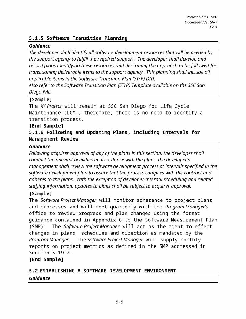
Project Name SDP Document Identifier
Date
The software design approach for the XY Project will be Object-Oriented Design (OOD). The methodology, definition of terms, and notation for new software design will be based on the Booch Method for OOD. This section describes the software design process and the artifacts produced by this process.Software design will occur incrementally. A top-level design for XY Project software will be developed during the architectural design phase. During the detailed design phase, the software necessary to meet the capabilities assigned to XY Project incremental builds will undergo detailed design to a level sufficient for implementation in support of targeted capabilities.A software architectural model of XY Project will be placed under developmental configuration management following the top-level design review. Updates and refinements to the model will occur incrementally during detailed design. An updated model will be placed under developmental configuration management following each successful formal inspection.The design step produces a data design, an updated architectural design, and a procedural design. The data design transforms the information model created during analysis into the data structures that will be required to implement the software. The procedural design transforms the functional model into a procedural description of the software. [End Sample]5.6.1 CSCI-Wide Design DecisionsGuidanceThe developer shall define and record CSCI-wide design decisions (that is, decisions about the CSCI’s behavioral design and other decisions affecting the selection and design of the SUs comprising the CSCI. The result shall include all applicable items in the CSCI-wide design section of the SDD. Design pertaining to interfaces may be included in SDDs or in IDDs and design pertaining to databases may be included in SDDs or DBDDs.[Sample]CSCI-wide software design decisions for the XY Project system software will be a continuous effort. The Software Project Manager will direct the conduct of design analyses and trade-offs through Software Design Team meetings involving all concerned. The Software Design Team will conduct domain analyses, evaluate CSCI-wide design issues, and formulate decisions for new development, reuse of existing components, and hardware/software architectures.The system-wide design principles for XY Project are listed below:
a. Establish an initial capability for XY Project upon which to build future enhancements b. Use COTS open system architecture hardware and system software componentsc. Maximize reuse of existing software application packages.
[End Sample]5.6.2 CSCI Architectural DesignGuidanceThe developer shall define and record the architectural design of each CSCI (identifying the SUs comprising the CSCI, their interfaces, and a concept of execution among them) and the traceability between the SUs and the CSCI requirements. The result shall include all applicable items in the architectural design and traceability sections of the SDD. Design pertaining to interfaces may be included in SDDs or in IDDs.
5-13

Project Name SDP Document IdentifierDate
Note: SUs may be made up of other SUs and may be organized into as many levels as are needed to represent the CSCI architecture. For example, a CSCI may be divided into three SUs, each of which is divided into additional SUs, and so on.[Sample]5.6.2.1 CSCI Architectural Modeling and Specification Process. 5.6.2.1.1 Purpose. The Architectural Design step transforms the model created during requirements analysis into the discrete software components that will be required to implement the system software. Detailed design transforms the software component architectural model into an implementation description of the software consisting of Software Units (SUs), their internal data, algorithms, interfaces, and control flow. The software architectural model of the project will be placed under developmental configuration management following the Formal Inspection of the architectural design. Updates and refinements to the model will occur incrementally during detailed design and the updated model will be placed under developmental configuration management following completion of the Formal Inspection of the detailed design.5.6.2.1.2 Roles and Responsibilites. The roles and responsibilities for this process are listed below:
a. Software Design Team performs analysis to create the functional model of the software system
b. SQA Group verifies process is performedc. IV&V Group validates traceabilityd. SCM Group performs configuration control of artifacts.
5.6.2.1.3 Entry Criteria. The entry criteria for this process are listed below:a. Formal modeling methodology selectedb. Engineering has been trained in the application of the modeling discipline.
5.6.2.1.4 Inputs. The inputs for this process are listed below:a. Approved SRSb. Build Plan with documented acceptance criteria.
5.6.2.1.5 Process Activity. The steps needed to complete this process are listed below:a. Review available documentation on requirements, assumptions, and constraints.b. Formulate and evaluate architectural alternatives.c. Select architectural model. Define software components and internal software units,
their interactions, data flow, and functional processes.d. Allocate known requirements to the architectural components.e. Identify and select COTS open system architecture hardware and system software
components.f. Maximize reuse of existing software application packages.g. Design and document the initial Graphical User Interface (GUI) and position actions.h. Document architectural design in formal design method (i.e., IDEF0, Inter-action
Diagrams, etc).i. Conduct technical review to ensure architectural design meets the requirements allocated
to software. Repeat process several times until architectural design meets approval.j. Develop initial database scheme to support the system software.k. Conduct a technical review of the GUI screen designs to ensure they satisfy system level
operational needs and conform to accepted Human Computer Interface (HCI) standards.
5-14

Project Name SDP Document Identifier
Date
l. Develop a traceability matrix between the components of the architectural design and the SRS.
m. The SQA Group and IV&V Group provide analysis and comment on architectural model and GUI design.
n. Conduct Formal Inspection of architectural design, its components/units and their functions, and interaction.
o. Update the architectural design based on the sum of the accumulated analysis and comments.
p. Software Project Manager accepts architectural model and requirements allocation.5.6.2.1.6 Outputs. The outputs from this process are listed below:
a. Documented and approved architectural design b. Documented GUI designc. Initial database scheme.
5.6.2.1.7 Exit Criteria. The exit criteria for this process are listed below:a. Architectural model accepted and under CM in Software Development Library (SDL)b. Requirements allocated to architectural components validated by the SQA Groupc. Documented GUI under CM.
5.6.2.1.8 Process Measurements. The following data shall be collected:a. Earned Value Schedule
Event % CompleteStart component level IDEF 0 diagrams 10IDEF 0 at component level complete and associated algorithms defined
40
Each software component’s SUs identified and structural relations defined
55
Architectural model trace to SRS complete 65Start Formal Inspection of Architectural Model 75Finish Formal Inspection and update of Architectural Model 90CCB Baselines GUI Screens, initial database scheme, and Architectural Model (IDEF 0)
100
b. Track % build allocated requirements traceable to architectural model componentsc. Track actual vs planned staff hours expended d. Track actual vs planned costs expended
5.6.2.2 CSCI Test Planning Process5.6.2.2.1 Purpose. The purpose of software test planning is to identify test resources and schedule, and identify tests cases and procedures necessary to the qualification of the developing software in a STP.5.6.2.2.2 Roles and Responsibilities. The roles and responsibilities for this process are listed below:
a. Software Test and Evaluation Group performs analysis to create a strategy for qualification of system software.
b. SQA Group verifies process is performed.c. IV&V Group validates traceability.d. SCM Group performs CM of artifacts.
5.6.2.2.3 Entry Criteria. The entry criteria for this process is listed below:
5-15

Project Name SDP Document IdentifierDate
a. SRS under CMb. Build Plan with targeted requirements and acceptance criteria.
5.6.2.2.4 Inputs. The inputs for this process are listed below:a. Approved SRSb. Build Plan with documented acceptance criteriac. Test requirements data base initialized.
5.6.2.2.5 Process Activity. The steps to complete this process are listed below:a. Perform analysis of software performance requirements documented in the SRS and
identified in Build Plan.b. Define test levels for software testing, including general test requirements, test cases (e.g.
stress, erroneous input, maximum capacity, and timing). Define the overall test concept and objectives supported by the defined tests.
c. Identify the environment in which tests will be conducted. Define plans for implementing and controlling the test environment.
d. Estimate the personnel and other resources required to support the test concept and objectives.
e. The Software Project Manager directs Software Test and Evaluation Manager to prepare, conduct, analyze data, and report the results of testing.
f. Trace software requirements allocated to the test cycle to defined test cases. Verify completeness of requirement’s traceability.
g. Develop a general schedule of defined tests, including time for problem correction and retest.
h. Draft the STP, following the instructions of the assigned documentation standard. Refine the test requirements database to create structure of test case and procedures with attribution on test characteristics.
i. The SQA and IV&V provide analysis and comment on the STP.j. Perform Formal Inspection to ensure that the STP meets the system requirements
allocated to software and is in context with the architectural model and GUI designs.k. Revise draft STP to correct discrepancies and incorporate recommended changes.l. The LCCB baselines the STP placing it in the SDL.
5.6.2.2.6 Outputs. The outputs of this process are listed below:a. Approved STPb. Test requirements database with attributed test case entries.
5.6.2.2.7 Exit Criteria. The exit criteria for this process are listed below:a. All SRS performance requirements allocated to defined test casesb. STP approved and under CM.
5.6.2.2.8 Process Measurements. The following data shall be collected:a. Earned Value Schedule
Event % CompleteStart Analysis 10Start Formal Inspection of STP 50Finish Formal Inspection and update to STP 75CCB Baselines STP in SDL 100
b. Track % build allocated testable requirements traceable to test cases identified in STPc. Track actual vs planned staff hours expended
5-16

Project Name SDP Document Identifier
Date
d. Track actual vs planned costs expended.[End Sample]5.6.3 CSCI Detailed DesignGuidanceThe developer shall develop and record a description of each software unit. The result shall include all applicable items in the detailed design section of the SDD. Design pertaining to interfaces may be included in SDDs or in IDDs and design of software units that are databases or that access or manipulate databases may be included in SDDs or in DBDDs.[Sample]5.6.3.1 Detailed Design Process5.6.3.1.1 Purpose. The purpose of Detailed Design is to incrementally define and describe the CSCI software components in terms of their SUs and the internal relationships of those SUs using detailed graphical representation. If development of detailed design identifies deficiencies in architectural design or software requirements, the Software Design Team will submit requirement changes and/or update the developmental architectural model as required.5.6.3.1.2 Roles and Responsibilities. The roles and responsibilities for this process are listed below:
a. Software Design Team performs analysis to create the detailed design of system software b. SQA Group verifies process is performedc. IV&V Group validates traceabilityd. SCM Group performs CM of artifacts.
5.6.3.1.3 Entry Criteria. The entry criteria for this process are listed below:a. Approved Software Architectural Designb. Approved SRSc. Approved GUI design.
5.6.3.1.4 Inputs. The inputs for this process are listed below. a. Documented and approved architectural designb. SRS, build plan, and attributed software requirements database c. Documented GUI designd. Initial database scheme.
5.6.3.1.5 Process Activity. The steps needed to complete this process are listed below:a. Construct graphical representation for each software component detailing the interaction
of its SUs. b. Add algorithm, data attributes, and operations to each SU.c. Draft Software Detailed Design (SDD) document.d. Provide traceability matrix from SUs to the parent requirement in the SRS and build
plan.e. The SQA Group and IV&V Group provide analysis and comment on the detailed design.f. Conduct Formal Inspection of the SDD by component, each component's SUs and their
functions and interaction. Repeat process several times until detailed design meets approval.
g. Update the SDD based on the sum of the accumulated analysis and comments.h. The LCCB baselines the SDD placing it in the SDL.
5-17

Project Name SDP Document IdentifierDate
5.6.3.1.6 Outputs. The output for this process is the SDD containing graphical representation of the detailed design, internal data, and algorithms definitions.5.6.3.1.7 Exit Criteria. The exit criteria for this process is the software components and their SUs graphical design representation, internal data, algorithms defined, reviewed and approved.5.6.3.1.8 Process Measurements. The following data shall be collected:
a. Earned Value ScheduleEvent % Complete
Start analysis 10Graphical representation complete and associated algorithms defined
40
SU structural relations, algorithms, and interfaces defined 55Draft SDD 65Start Formal Inspection of SDD 75Finish Formal Inspection of SDD 90LCCB Baseline SDD 100
b. Track % build allocated requirements traceable to SUs described in the SDDc. Track actual vs planned staff hours expended d. Track actual vs planned costs expended.
5.6.3.2 Test Case Design Process5.6.3.2.1 Purpose. The Software Test and Evaluation Group will design the set of test cases defined in the STP. The design will be in keeping with the overall test concept and objectives of the STP to verify the software meets all performance requirements allocated to the functional components of the architectural design.5.6.3.2.2 Roles and Responsibilities. The roles and responsibilities for this process are listed below:
a. Software Test and Evaluation Group performs analysis to design the test casesb. SQA Group verifies process is performedc. IV&V Group validates traceabilityd. SCM Group performs CM of developed artifacts.
5.6.3.2.3 Entry Criteria. The entry criteria for the process is that the STP is published and under CM.5.6.3.2.4 Inputs. The inputs for this process are listed below:
a. Baselined SRSb. Baselined STPc. Baselined Architectural Design.
5.6.3.2.5 Process Activity. The steps needed to complete this process are listed below:a. Define the test case(s) identified in the draft STD, expressing the purpose and conditions
associated with each test case and identify included test procedures. For each test case, perform the following activities:1) Define the inputs (stimuli to the component under test) required to fulfill the test
purpose.2) Define the expected results (outputs from the component under test in response to
inputs) required to fulfill the test purpose.3) Define insertion and extraction methods to/from the component under test. Identify
points of data input/output and volumes of data.
5-18

Project Name SDP Document Identifier
Date
4) Define evaluation criteria for test results analysis. Define ranges of values, capacities, and times for test pass/fail.
5) Identify test procedure suite (i.e., required discrete procedures).6) Identify test environment configuration, interface drivers, database loaders,
controllers/monitors, and other test tools to support test case purposes.b. Trace SRS performance requirements to specific test procedures within the test cases.c. The SQA Group and IV&V Group provide analysis and comment on the test case
description.d. Perform Formal Inspection to ensure that the test case design meets the system
requirements allocated to functional component.e. Revise draft test case descriptions to correct discrepancies and incorporate recommended
changes.f. The LCCB baselines the test case designs placing them in the SDL.
5.6.3.2.6 Outputs. The output from this process is the approved test case descriptions in STD format.5.6.3.2.7 Exit Criteria. The exit criteria for this process are listed below:
a. Baselined test case descriptionsb. Functional component performance requirements allocated to test case procedures suite.
5.6.3.2.8 Process Measurements. The following data shall be collected:a. Earned Value Schedule
Event % CompleteStart Analysis 10Start Technical Review of test case design 50Finish Technical Review and update test case design
75
LCCB Baseline test case design 100b. Track % build allocated testable requirements traceable to test procedures defined for the
test cases.c. Track actual vs planned staff hours expended.d. Track actual vs planned costs expended.
[End Sample]
5.7 SOFTWARE IMPLEMENTATION AND UNIT TESTINGGuidanceThis paragraph shall be divided into the following subparagraphs to describe the approach to be followed for software implementation and unit testing. The planning in each subparagraph shall cover all contractual clauses regarding the identified topic.[Sample]The purpose of Software Implementation and Unit Testing is to implement and test the detailed design for SUs into new code, or as modifications of existing NDI code following documented programming style guidelines.The following paragraphs describe Software Implementation and Unit Testing processes. [End Sample]
5-19

Project Name SDP Document IdentifierDate
5.7.1 Software ImplementationGuidanceThe developer shall develop and record software corresponding to each SU in the CSCI design. This activity shall include, as applicable, coding computer instructions and data definitions, building databases, populating databases and other data files with data values, and other activities needed to implement the design. For deliverable software, the developer shall obtain acquirer approval to use any programming language not specified in the contract. [Sample]5.7.1.1 Purpose. The purpose of software implementation and unit testing is to create qualification test ready CSCI functional components by implementing and testing each components SUs as identified in the detailed design. This may involve developing new code and/or modifications of existing code, and following documented programming style guidelines.5.7.1.2 Roles and Responsibilities. The roles and responsibilities for this process are listed below:
a. Software Production Team performs code/unit test and/or COTS selectionb. SQA Group verifies process is performed and validates SDFsc. IV&V Group validates traceabilityd. SCM Group performs CM of artifacts.
5.7.1.3 Entry Criteria. The entry criteria for this process are listed below:a. SDD containing graphical representation of the detailed design, internal data, and
algorithms definitions baselined.b. Software units allocated to individual engineers for production and test.c. SDF formats defined.d. Programming style guides defined.e. Engineering staff has completed required training on project processes, style guidelines,
and tools.5.7.1.4 Inputs. The inputs for this process are listed below:
a. Baselined SRS and build planb. Baselined SDDc. Approved GUI designd. Initial database scheme.
5.7.1.5 Process Activity. The steps needed to complete this process are listed below:a. Review requirements allocated to the SUs, the SDD, and programming style guidelines.b. Maintain working source for assigned task within the SDF.c. Compile software.d. Perform tracing of each SU implementation to the parent software component in the
SDD.e. Review all inputs and outputs for each software unit. Identify any test drivers necessary
to stimulate unit execution, provide inputs, and capture final outputs. Identify all interfaces to other units and determine if other units are available or if unit stubs must be written.
f. Identify the various paths that may be taken by the unit (a McCabe complexity analysis tool may be used to determine the unit paths). Identify data variables and conditions that determine which paths are taken. Identify parameter limits for all input, output, and
5-20

Project Name SDP Document Identifier
Date
control parameters. Examine and list all error handling facilities of the units and error conditions.
g. Identify a set of unit tests to conduct the required testing (path testing, boundary condition testing, and input validation and syntax testing). There should be a test for each path through the unit, to test the upper and lower limits of all parameters, and to test all error conditions (pass and fail). Write step-by-step procedures for each test case.
h. Document the unit tests in the SDF.i. Conduct technical review of each SUs implementation and unit tests. Resolve all
comments.j. Perform the test in accordance with the unit test plan.k. Compare test results with expected results and SU acceptance criteria (e.g., 80% path test
analysis successful). Document the results in the SDF. If discrepancies are found, attempt to determine whether the errors are associated with the software, test/test driver, or hardware. Rework as required.
l. The SQA Group and IV&V Group provide analysis and comment on the content of the SDFs.
m. The Software Production Team, upon successful completion of the unit test for a software components included SUs, promotes the software component for integration testing, and submits the software component for developmental CM in the SDL.
n. Document and report requirement and/or design errors/inconsistencies.o. Update metrics information, including defect analysis database.
5.7.1.6 Outputs. The outputs from this process are listed below:a. Current SDFsb. Updated SDL (includes qualified SUs)c. Defect database.
5.7.1.7 Exit Criteria. The exit criteria for this process are listed below:a. Updated SDFb. Successfully tested unitsc. Metrics database updated with defect information from SU technical review and unit
testingd. SU’s checked into SDL ready for integration.
5.7.1.8 Process Measurements. The following data shall be collected:a. Earned Value Schedule(Note: Earned value will be tracked against SDF contained SU set (i.e. a software component))
Event Report % Complete
Start Code and Unit Test of component SUs 10Complete Code and Unit Tests draft 50Tracing of each SUs Unit Test to component allocated requirements complete
60
SU implementation technical review complete 70Execution of Unit Test Complete, SU source code and Unit Tests updated
85
Component SDF validated by QA and IV&V 90
5-21

Project Name SDP Document IdentifierDate
Component SU Code Checked into SDL 100b. Track % actual number of SUs completing code and unit test against build’s total number
of SUs.c. Track SLOC developed, reused, and modified to facilitate process modeling and
estimation.d. Collect for process defect analysis P/CRs, and their origin (i.e., code logic, design,
requirements, etc).e. Track actual vs planned staff hours expended.f. Track actual vs planned costs expended.
[End Sample]5.7.2 Unit TestingGuidanceThe developer shall establish test cases (in terms of inputs, expected results, and evaluation criteria), test procedures, and test data for testing the software corresponding to each SU. The test cases shall cover all aspects of the unit’s detailed design. The developer shall record this information in the appropriate SDFs.[Sample]The purpose of the unit testing addressed in Section 5.7.1 is to identify and correct as many internal logic errors as possible. Problems not uncovered by unit testing are, in general more difficult to isolate when uncovered at the CSCI level. Unit testing will be conducted throughout the implementation process, first as part of the initial development process and later as changes to the unit are made. Unit tests will be repeatable and may be conducted at any point in the implementation process in accordance with the approved unit test plan. For the purposes of unit testing, a unit is an object. The goal for unit testing by developers is to perform path testing in which every affected branch is navigated in all possible directions at least once and every affected line of code is executed at least once. Unit test drivers and stubs will be developed as needed and will be placed under CM as part of the overall test utility. All unit test results will be recorded in the SDFs.[End Sample]5.7.3 Test Case/Procedure ImplementationGuidanceThe developer shall implement the test cases in terms of their test procedures and test data for verifying the software requirements corresponding to each CSCI.[Sample]5.7.3.1 Purpose. The purpose of this process is to develop detailed steps for controlling tests, injecting inputs, recording results, and comparing actual to expected results. Document test case procedures in the final STD.5.7.3.2 Roles and Responsibilities. The roles and responsibilities for this process are listed below:
a. Software Test and Evaluation Group performs analysis to implement the test case defined test procedures
b. SQA Group verifies process is performedc. IV&V Group validates traceabilityd. SCM Group performs CM of developed artifacts.
5-22

Project Name SDP Document Identifier
Date
5.7.3.3 Entry Criteria. The entry criteria for this process are listed below:a. Test cases designedb. Software performance requirements allocated to test cases c. GUI screens designed.
5.7.3.4 Inputs. The inputs for this process are listed below:a. GUI screen and/or operator manualb. Test case designs.
5.7.3.5 Process Activities. The steps needed to complete this process are listed below:a. Review software GUI and/or operator manuals to identify methods of operator input, use
of simulator/emulator tools, and software data recording.b. Define and document detailed test procedure steps for providing inputs for test cases.c. Prepare input data files to provide test stimuli. Prepare operator logs for the component
under test as well as the test environment. d. Define evaluation steps for conducting post-test analysis and comparing actual and
expected test results.e. Define and document the test procedures in the STD following the instructions of the
assigned documentation standard. f. (Recommended Option). Develop test harness with automated test procedures and test
result analysis.g. Trace specific test case procedures to requirements allocated to parent test case.h. The SQA Group and IV&V Group provide analysis and comment on the test procedures.i. Conduct a technical review to verify consistency of the STD test procedures (or test
harness/procedures) with the test case descriptions, the STP, baselined requirements, and planning documents. Recommend revisions, as appropriate.
j. Revise draft STD (or test harness/procedures) to correct discrepancies and incorporate recommended changes to test case definitions and test procedures.
k. The LCCB baselines the test procedures in the STD placing them in the SDL.5.7.3.6 Outputs. The outputs from this process are listed below:
a. Baselined STD containing test procedures b. Test data files compiled.
5.7.3.7 Exit Criteria. The exit criteria for this process is that the STD is approved and under CM.5.7.3.8 Process Measurements. The following data shall be collected:
a. Earned Value Schedule(Note: Earned Value will be tracked against each Test Case Procedure suite)
Event % CompleteStart Test Case Procedures development 10Complete Test Case Procedures draft 50Tracing of Test Case Procedures to test case allocated requirements complete
60
Test Procedure Technical Review complete 70LCCB Baselines STD Test Procedures into SDL 100
b. Track total number of test procedures required to implement all test casesc. Track % test procedures completed d. Track actual vs planned staff hours expended
5-23

Project Name SDP Document IdentifierDate
e. Track actual vs planned costs expended [End Sample]
5.8 UNIT INTEGRATION AND TESTINGGuidanceThis paragraph shall describe the approach to be followed for unit integration and testing. Note: Unit integration and testing means integrating the software corresponding to two or more SUs, testing the resulting software to ensure that it works together as intended, and continuing this process until all software in each CSCI is integrated and tested. The last stage of this testing is developer-internal CSCI testing. [Sample]5.8.1 PurposeThe purpose of integration and test is to incrementally integrate SUs into larger software components, and components into a complete system. Testing is performed to validate each component's ability to meet its stated requirements and to ensure interoperability of the major software components. Integration continues until all software components are integrated with the system-level hardware suite into a single functioning system.5.8.2 Roles and ResponsibilitiesThe roles and responsibilities for this process are listed below:
a. Software Test and Evaluation Group plans, integrates, and executes testsb. Software Development Group performs updates in response to developmental P/CRs c. SQA Group verifies process is performed and validates test resultsd. IV&V Group validates traceability of successful tests runse. SCM Group performs configuration control of test reports, and updated project artifacts.
5.8.3 Entry CriteriaThe entry criteria for this process are listed below:
a. STPb. Build Plan and schedulec. Any previous integration test reportsd. Approved architectural designe. Approved STD with Test Procedures.
5.8.4 InputsThe inputs for this process are listed below:
a. Updated SDL (includes qualified SUs)b. Baselined STD (includes execution ready test cases with included test procedures)c. Integration Test Report form d. P/CR formse. Test drivers and test inspection tools as required by STD
5.8.5 Process ActivitiesThe steps needed to complete this process are listed below:
a. Software Test and Evaluation Group reviews the Build Plan and schedule, the list of software units/components to be included in the build, and the results of any previous integration tests to determine the software and software fixes to be tested. Determine a set of test cases to be used to test the build.
5-24

Project Name SDP Document Identifier
Date
b. For the requirements identified for the build, develop an integration test plan. The integration test plan should identify the sequence of SU and component integration, traceability to the requirements to be validated by the test, test tools and drivers to be used, and the applicable test cases including procedures for conducting the test and analyzing the results. Document the integration test plan.
c. Perform a Technical Review of the integration test plan and resolve all comments.d. Software Test and Evaluation Group places the integration test plan under developmental
configuration control.e. Integration Test Team requests and receives increment build, installs it in the integration
test area.f. Conduct the test in accordance with the integration test plan procedures. Record test
results as they are observed.g. Perform any required post test analysis or data reduction to determine pass/fail criteria as
specified in the integration test plan.h. Compare test results with expected results. If discrepancies are found, attempt to
determine whether errors are associated with the software, test/test driver, or hardware.i. Document all test results using the project integration test report form. This report
should contain all data recorded from test tools, test results, and deviations from the test plan. Document any problems detected on a P/CR form. Document requirements satisfactorily tested in the test report.
j. Determine if another incremental build is required. Proceed with activity (e) above if needed. If not proceed to next step.
k. The SQA Group and IV&V Group provide analysis and comment on the test results.l. Software Test and Evaluation Manager reviews the integration test report and any P/CRs
for accuracy and thoroughness. File the test report in the project history file in the document library and submit a copy of the test report and P/CRs to the Software Development Manager for review and analysis.
m. TheLCCB baselines all updated developmental and test artifacts placing them in the SDL.
5.8.6 OutputsThe outputs from this process are listed below:
a. Updated SDFsb. Updated SDL (i.e., source code and test procedures)c. Project History File updated with test resultsd. P/CRs submitted for all detected problems.
5.8.7 Exit CriteriaThe exit criteria for this process are listed below:
a. Integration test report reviewed and approvedb. All build allocated testable requirements have been successfully testedc. CCB baselines SDL with updated source code and test proceduresd. Project History File updated with test results.
5.8.8 Process MeasurementsThe following data shall be collected:
a. Earned Value ScheduleEvent % Complete
5-25

Project Name SDP Document IdentifierDate
Start Analysis 10Integration test plan drafted 20Integration test plan completes Technical Review 35Initial increment test begins 50Incremental integration testing completed 80Test results validated by QA and IV&V 90LCCB Baseline updated SDL artifacts 100
b. Track % build allocated testable requirements successfully completing integration test(Note: Test Procedures trace to testable requirements. See Test Case Design)
c. Track SU successfully completing integration as a percent of total targeted for integrationd. Track open versus closed STRse. Track actual vs planned staff hours expended f. Track actual vs planned costs expended.
[End Sample]
5.9 CSCI QUALIFICATION TESTINGGuidanceThis paragraph shall describe the approach to be followed for CSCI qualification which is performed to demonstrate to the acquirer that CSCI requirements have been met. It covers the CSCI requirements in SRSs and in associated IRS. [Sample]The CSCI Test Team will conduct CSCI Qualification Testing on each of the XY Project CSCIs. The purpose of CSCI Qualification Testing is to verify satisfaction of CSCI performance requirements as documented in the SRS. The following paragraphs describe CSCI Qualification Testing processes and assignment of responsibilities. The STP and STDs will provide the detailed plan and design for CSCI Qualification Testing in conformance with these processes.Off-The-Shelf CSCIs, both COTS and GOTS, will be qualified in accordance with the SSC San Diego COTS Evaluation, Selection, and Qualification process, reference (g).5.9.1 Independence in CSCI Qualification TestingThe Software Test and Evaluation Manager will be responsible for CSCI Qualification testing, reporting directly to the Software Project Manager. The Software Test and Evaluation Manager will designate a Test Director and assign personnel to the CSCI Test Team. 5.9.2 Testing on the Target Computer SystemCSCI Qualification testing for XY Project will take place only on the target computer system, interfaced with hardware and software components of the software test environment. This restriction will assure that testing of timing, capacity, throughput, and responsiveness of XY Project CSCI components with respect to performance requirements can be accurately assessed. 5.9.3 Performing CSCI Qualification testing5.9.3.1 Purpose. The purpose of CSCI Qualification Testing is to validate satisfaction of requirements documented in the SRS and targeted for a specific build. CSCI Qualification Testing is to ensure suitability for release to an external test agency and/or user community. The STP and STDs will provide the detailed plan and design for Software Qualification Testing
5-26

Project Name SDP Document Identifier
Date
5.9.3.2 Roles and Responsibilities. The roles and responsibilities for this process are listed below:
a. CSCI Test Team executes testsb. Software Development Group performs updates in response to developmental P/CRs c. SQA Group verifies process are performed and validates test resultsd. IV&V Group validates traceability of successful tests runse. SCM Group performs configuration control of test reports, and updated project artifacts
5.9.3.3 Entry Criteria. The entry criteria for this process are listed below:a. Software components under baseline controlb. Unit, and Unit Integration Testing completedc. High priority P/CRs resulting from integration testing closedd. Software test materials completede. Software test environment certifiedf. Approved Build Plan and scheduleg. Approved architectural designh. Approved SDT with Test Proceduresi. Integration and test of system software completed and report approved.
5.9.3.4 Inputs. The inputs for this process are listed below:a. Updated SDL (includes fully tested SUs)b. Baselined STD (includes execution ready test cases with include test procedures)c. Integration Test Report d. P/CR formse. Test drivers and test inspection tools as required by STD.
5.9.3.5 Process Activities. The steps needed to complete this process are listed below:a. Software Test and Evaluation Manager conducts Test Readiness Review (TRR) with the
Software Development Manager to address the following issues:1) Verify high priority P/CRs resulting from integration testing are closed and
corrections tested.2) Verify STP and STDs are complete and under control.3) Verify software test materials (e.g. data files, test environment, and Component
operator logs) are complete and in conformance with STDs.4) Verify test environment is certified and operational. Verify that test environment
configuration logs are up-to-date.b. The Software Project Manager working with the Software Test and Evaluation Manager
complete TRR. Authorize start of CSCI Qualification Testing or direct correction of discrepancies in STP, STD, test materials, and test environment configuration, as necessary and including return to the integration and test process.
c. CSCI Test Team loads and initializes software to meet prescribed test conditions for execution of complete test case suite.
d. Execute tests, following scripted test steps. Record results on operator logs and automated recording media.
e. Process recorded test data to reduce and format them in textual and graphic form.f. Review test case purposes and expected results documented in the STD.g. Evaluate actual test results by examining the Test History log, P/CRs, and recorded test
data.
5-27

Project Name SDP Document IdentifierDate
h. Ensure P/CRs opened during software testing have been tested and closed. i. Ensure that adequate regression testing of the updated version has been conducted and
any resulting P/CRs have been tested and closed.j. Determine degree of compliance to acceptance criteria and record percent requirements
satisfactorily tested.k. Write test recommendations, promotion to more complex testing, retest, or system
acceptance.l. Prepare draft test report, following the instructions of the assigned documentation
standard. Include calculated test metrics data. Append marked-up data from the STD, processed recorded test data to support test results and recommendations.
m. The Software Test and Evaluation Manager, IV&V Manager and the SQA Manager will review the draft test report to verify consistency of the report with recorded result data. Recommend revisions, as appropriate.
n. Revise draft test report to correct discrepancies and incorporate recommended changes.o. The Software Project Manager will approve acceptance or direct corrective action as
necessary. This may include P/CR repair and re-qualification testing, or a return to integration and test.
p. LCCB baselines updated SDL artifacts to establish final system build configuration.5.9.3.6 Outputs. The outputs from this process are listed below:
a. Updated SDL b. Final Test Reportc. Defect data collected for process analysis.
5.9.3.7 Exit Criteria. The exit criteria for this process are listed below:a. Test results logged, including percent targeted requirements satisfactorily tested and
degree of compliance to acceptance criteria.b. Recorded test data processed.c. Measurement database updated.d. Test report indicating acceptance approved.e. LCCB baselines components comprising the qualified system.
5.9.3.8 Process Measurements. The following data shall be collected:a. Earned Value Schedule
Event % CompleteStart TRR 10Initiate Qualification Test 25Complete Qualification Test Cycle 80Complete Review final Test Report 85Software Project Manager approves Test Report recommendation for acceptance
90
LCCB Baselines Test Report and updates SDL 100b. Track % build allocated testable requirements successfully completing qualification testc. Track open versus closed P/CRsd. Track actual vs planned staff hours expended e. Track actual vs planned costs expended.
[End Sample]
5-28

Project Name SDP Document Identifier
Date
5.10 CSCI/HWCI INTEGRATION AND TESTINGGuidanceThis paragraph shall describe the approach to be followed for participating in CSCI/HWCI integration and testing. The planning in each subparagraph shall cover all contractual clauses regarding the identified topic.Note 1: CSCI/HWCI integration and testing means integrating CSCIs with interfacing HWCIs and CSCIs, testing the resulting groupings to determine whether they work together as intended, and continuing this process until all CSCIs and HWCIs in the system are integrated and tested. [Sample]Upon completion of the testing and integration of all builds and the preliminary integration testing of all CSCI components comprising the XY Project, the software is ready for CSCI/HWCI integration testing. CSCI/HWCI testing will be conducted in accordance with the STP and the applicable STD after successful completion of a Test Readiness Review. The objective is to validate that the XY Project hardware and software components can individually be interfaced in accordance with the SRS and IRS/IDD requirements and that the components taken as a system are stable enough to proceed with System Qualification Testing. These tests are formally conducted by a test team composed of personnel from the System Test Organization, and in conjunction with the software developers. The IV&V Group will be present during these tests as an observer. A Software Test Report (STR) is prepared to document the results of the test, as delineated in the STP. 5.10.1 Preparing for CSCI/HWCI Integration and TestingPreparation for integration and testing of software and hardware will require the acquisition of the HW and/or HW simulators in configurations to support all planned platforms Test plans and procedures will need to be developed and implemented. The System Test Organization in preparing for CSCI/HWCI Qualification Testing will perform the following processes:5.10.1.1 Plan Software Tests Process. The System Test Organization will plan CSCI/HWCI software tests, identify test resources and schedule, and prepare the inputs to the STP.5.10.1.2 Develop Test Cases Process. The System Test Organization will develop a set of test cases in keeping with the overall test concept and objectives that adequately verify all allocated performance requirements for the CSCI.5.10.1.3 Develop Test Procedures Process. The System Test Organization will develop detailed steps for controlling tests, injecting inputs, recording results, and comparing actual to expected results. Once verified, the System Test Organization will document test cases and steps in the STD.5.10.1.4 Prepare Test Environment Process. The System Test Organization will define, develop, integrate, verify, and place a test environment under control that will support the CSCI test concept and objectives.5.10.1.5 Assuring Readiness for Hardware Configuration Item/Computer Software Configuration Item Integration and Testing. The testing will be performed with the equipment at the Program Manager’s designated System Test Organization. The System Test Organization will verify that the software and hardware is under baseline control; informal testing of the CSCI component has been completed satisfactorily; informal testing of the hardware has been completed satisfactorily; test materials are completed; and test personnel and other resources are ready for the start of CSCI/HWCI testing.
5-29

Project Name SDP Document IdentifierDate
5.10.1.6 Conduct Test Readiness Review. As a step preliminary to the conduct of CSCI/HWCI integration and testing, a review of the individual components or activities which go into the makeup of the testing will be conducted by the Program Manager in the form of a Test Readiness Review (TRR).5.10.2 Performing CSCI/HWCI Integration and TestingThe System Test Organization will execute CSCI tests in the controlled test environment and collect data recorded by operators and automated means during testing.5.10.3 Revision and RetestingRevision and re-testing of a CSCI depends on analysis of test results and correct identification of problems detected during both test conduct and post-test analysis. Therefore, one of the processes described incorporates revision and re-testing. 5.10.4 Analyzing and Recording CSCI/HWCI Integration and Test ResultsThe final results of the XY Project CSCI/HWCI integration and testing will be documented. The test report will be distributed for review and approval. 5.10.4.1 Analyze and Evaluate Results, Revise Tests Process. The System Test Organization will compare recorded and processed CSCI/HWCI integration and testing results data with expected results to identify, isolate, and assess the probable causes of errors in the CSCIs under test, hardware, test environment, or test materials. Assigned test personnel will revise tests or prepare P/CRs, as required.5.10.4.2 Report Test Results Process. The System Test Organization will evaluate the results of CSCI/HWCI integration tests, determine that test results meet defined objectives, determine that P/CRs are closed and tested, and publish the STR.[End Sample]
5.11 SYSTEM QUALIFICATION TESTINGGuidanceThis paragraph shall describe the approach to be followed for participating in system qualification testing. The planning in each subparagraph shall cover all contractual clauses regarding the identified topic.Note 1: System qualification testing is performed to demonstrate to the acquirer that system requirements have been met. It covers the system requirements in the SSSs and in associated IRSs. This testing contrasts with developer-internal system testing, performed as the final stage of CSCI/HWCI integration and testing.Note 2: If a system is developed in multiple builds, qualification testing of the completed system will not occur until the final build. System qualification testing in each build should be interpreted to mean planning and performing tests of the current build of the system to ensure that the system requirements to be implemented in that build have been met.[Sample]XY Project System Qualification Testing consists of complementary and progressive test phases. Once CSCI/HWCI integration and testing is completed by the System Test Organization, System Qualification Testing (SQT) begins. A single STP will be generated to address the planning for all levels of software SQT. A STD will be generated for each CSCI component, documenting the test procedures to be run to verify each requirement in the SRS for that component. A cross reference matrix will be provided, using the project wide requirements traceability database, to document the test or tests that
5-30

Project Name SDP Document Identifier
Date
satisfy each SRS requirement. A STR will be generated for each CSCI component, documenting the results of each CSCI component test. The System Test Organization is responsible for generating the appropriate test documentation. The Software Project Manager is responsible for conduct of the tests. The software developers will be responsible for supplying test procedures for SUs they develop to the System Test Organization for each CSCI component so that they can be incorporated into the STD for system. The System Qualification Testing (SQT) test will be used to validate the entire systems performance. The System Qualification Testing (SQT) is the Program Manager’s approved and witnessed series of tests that demonstrate compliance with the requirements set forth in the SSS. The SQT is the acceptance mechanism for the developer’s compliance with the terms of tasking by the Program Manager.[End Sample]5.11.1 Independence in System Qualification TestingGuidanceThe person(s) responsible for fulfilling the requirements in this section shall not be the persons who performed detailed design or implementation of software in the system. This does not preclude persons who performed detailed design or implementation of software in the system from contributing to the process, for example, by contributing test cases that rely on knowledge of the system’s internal implementation.[Sample]The SQT shall be accomplished by the System Test Organization. This is done to ensure that the product accepted by the government meets all system requirements. The Program Manager may approve on a case-by-case basis the use of the developer’s test staff as SQT testers. However, the conduct of these tests shall remain the responsibility of the System Test Organization.[End Sample]5.11.2 Testing on the Target Computer SystemGuidanceThe developer’s system qualification testing shall include testing on the target computer system or an alternative system approved by the acquirer.[Sample]The target computer system shall be used for all SQT testing. In the event that commercial equivalents are the only system available, System Engineering shall certify that the commercial equivalent system has the same functional characteristics as the Target Computer System. If the systems are not equivalent, then the follow-on tests will include a test sample of those procedures that could not be run on the Target Computer System.[End Sample]5.11.3 Preparing for System Qualification TestingGuidanceThe developer shall participate in developing and recording the test preparations, test cases, and test procedures to be used for system qualification testing and the traceability between the test cases and the system requirements. For software systems, the results shall include all applicable
5-31

Project Name SDP Document IdentifierDate
items in the STD. The developer shall participate in preparing the test data needed to carry out the test cases and in providing the acquirer advance notice of the time and location of SQT.[Sample]SQT will be conducted at the System Test Organization facilities. Following SQT, the program then proceeds to a series of Demonstration Tests (DTs). An Operational Evaluation (OPEVAL) may or may not be conducted based upon the changes to the System Baseline. Since tests following SQT are performed by external agencies, the processes for these tests have not been discussed. [End Sample]5.11.4 Dry Run of System Qualification TestingGuidanceIf system qualification testing is to be witnessed by the acquirer, the developer shall participate in dry running the system test cases and procedures to ensure that they are complete and accurate and that the system is ready for witnessed testing. The developer shall record the software-related results of this activity in appropriate SDFs and shall participate in updating the system test cases and procedures as appropriate.[Sample]The system test procedures will be reviewed and approved prior to conduct of the SQT. This will allow the developers and testers an early view into problems and issues that might not otherwise be revealed until system testing. [End Sample]5.11.5 Performing System Qualification TestingGuidanceThe developer shall participate in system qualification testing. This participation shall be in accordance with the system test cases and procedures.[Sample]The SQT is intended to verify program performance in accordance with the SSS for the XY Project and those requirements specifications referenced from the SRS. The test will include all functional areas and interfaces to verify the functionality of a totally integrated program. Program reliability will be evaluated during independent functional and simultaneous operations, and in light and dense tactical environments. All functions and subsystem interfaces will be independently tested in a systematic manner. Approved test procedures will be developed to allow for repeatability of tests and to facilitate performance analysis. System performance will be visually analyzed, augmented by automated data collection, and results will be recorded by test personnel.SQT components and objectives are listed below:
a. Functional Tests - Functional Tests comprise two parts: Functional Operability Testing (FOT) and Functional Stress Testing (FST). FOT and FST test the functional requirements and the functional stress requirements of the SRS. FOT and FST are combined within a single set of procedures.
b. Interface Validation Tests (IVT) - IVTs comprise three parts: Interface Message Tests (IMT), Interface Recovery Tests (IRT) and Interface Stress Tests (IST). These three components test all interface messages, software recovery from interface protocol errors,
5-32

Project Name SDP Document Identifier
Date
and software response to interface stress, respectively. All IVTs are run with simulators, and to the degree feasible, will be conducted prior to SQT.
c. Regression Tests - Regression tests are run to verify that program changes implemented following the beginning of SQT testing have not introduced program regression. System tests including a casualty test, is included in the Regression Test set.
d. Single Unit Tests - Single Unit Tests are performed for each of the XY Project functional areas to validate the program operation individually in a one-on-one link.
e. Multiple Unit Tests - Multiple Unit Tests are performed simultaneously for all of the XY Project functional areas to validate the program operation in a multi-unit environment.
f. Stress and Endurance Test - The Stress and Endurance Test is designed to satisfy the stress and endurance requirements for critical computer programs. Three periods of maximum stress are distributed throughout a 25 hour period. The program must operate continuously for 25 hours without resulting in a Priority 1 or 2 P/CRs to pass this test.
g. P/CR Correction/Closure Tests - These test are executed to verify fixes to problems and to concur with the decision to close.
Specific SQT requirements and processes will be specified in the STP. [End Sample]5.11.6 Revision and RetestingGuidanceThe developer shall make necessary revisions to the software, provide the acquirer advance notice of retesting, participate in all necessary retesting, and update the SDFs and other software products as needed, based on the results of system qualification testing.[Sample]The Regression Test (RT), a set of high level tests, will perform a representative sampling of critical XY Project functions. It will run against a newly delivered operational program during SQT to examine the possibility of regression between the new and previous program versions. The RT is intended to serve as "system checkout" and should retain a measure of simplicity to ensure that results may be compared from one run to the next. Requirements for this test will be derived from mission-critical functions and casualty requirements identified in the SSS. Specific mission-critical functions are chosen which ensure that failure among them does compromise the overall effectiveness of the XY Project. Testing will be done in a laboratory environment.[End Sample]5.11.7 Analyzing and Recording System Qualification Test ResultsGuidanceThe developer shall participate in analyzing and recording the results of system qualification testing. For software systems, the result shall include all applicable items in the STR.[Sample]Test procedures shall be prepared for each event to be tested in SQT and shall contain clear identification to link it to its particular level of test, as well as to define test objectives. These test procedures shall contain the expected results, a pass/fail notation, and a summary, if applicable. Evaluations of test data shall provide the basis for a pass/fail determination leading to eventual acceptance or non-acceptance of the program. Problems in either software or design documentation or user manuals shall be documented as a P/CR.
5-33

Project Name SDP Document IdentifierDate
A P/CR is a report describing an existing problem in a computer program or its support documentation. Some P/CRs may, in fact, report a design enhancement rather than a design problem, in which case that PR will eventually be closed-out by submission of an ECP. The P/CRs database contains the following kinds of data: P/CR name, P/CR number, P/CR description, a category specification, a severity specification, and a process state status code. In addition, the P/CR database incorporates a routing system to direct the handling of each P/CR from station to station such as entry, analysis, approval, design, code, test, acceptance, and closure. The P/CR database program retains comments generated by each station as it advances through the route. The P/CR database program generates a variety of reports by selected category in specified order. [End Sample]
5.12 PREPARING FOR SOFTWARE USEGuidanceThis paragraph shall describe the approach to be followed when preparing for software use. The planning in each subparagraph shall cover all contractual clauses regarding the identified topic.Note: If software is developed in multiple builds, the developer’s planning should identify what software, if any, is to be fielded to users in each build and the extent of fielding (for example, full fielding or fielding to selected evaluators only). Preparing for software use in each build should be interpreted to include those activities necessary to carry out the fielding plans for that build.[Sample]The Delivery Team is responsible for correctly packaging the software consistent with the Build Plan and according to the XY Project documented processes.[End Sample]5.12.1 Preparing the Executable SoftwareGuidanceThe developer shall prepare the executable software for each user site, including any batch files, command files, data files, or other software files needed to install and operate the software on its target computer(s). The result shall include all applicable items in the executable software section of the Build Plan.[Sample]The executable software will be prepared for each user site, including any batch files, command files, data files, or other software files needed to install and operate the software on its target computer(s). The result is included in the executable deliverable portion of the Program Package (PP) as documented in the Build Plan.[End Sample]5.12.2 Preparing Version Descriptions for User SitesGuidanceThe developer shall identify and record the exact version of software prepared for each user site. The information shall include all applicable items in the SVD.[Sample]The Software Version Description (SVD) identifies and describes a version of a CSCI component or interim change (i.e., changes that occur between CSCI versions) to the previously released version. The SVD records data pertinent to the status and usage of a CSCI version or
5-34

Project Name SDP Document Identifier
Date
interim change. It is used to release CSCI versions or interim changes to the customer and will be included in the Program Package (PP). [End Sample]5.12.3 Preparing User ManualsGuidanceThe developer shall prepare user manuals in accordance with the following requirements.Note: Few, if any, systems will need all of the manuals in this section. The intent is for the acquirer, with input from the developer, to determine which manuals are appropriate for a given system and to require the development of only those manuals. The manuals in this section are normally developed in parallel with software development, ready for use in CSCI testing.[Sample]User Manuals will be prepared by the Software Development Group and validated by the Software Test and Evaluation Group. The Software Librarian will baseline the User Manuals, and provide copies as part of the deliverable Program Package (PP).[End Sample]5.12.4 Installation at User SitesGuidanceThe developer shall:
a. Install and check out the executable software at the user sites specified in the contractb. Provide training to users as specified in the contractc. Provide other assistance to user sites as specified in the contract.
[Sample]Installation and integration schedules must be developed and site surveys completed prior to development of the individual Program Packages (PP). The installation can begin at the completion of system development. All hardware and software components must be assembled and tested in a lab environment prior to being shipped to the user site. The XY Project software and hardware systems will then be shipped to the user site and installed and checked out by the designated Delivery Team. Each Delivery Team will identify needed training and prepare training materials. Training should be provided to users at the time of installation. Other assistance, such as user consultation, must be readily available after installation of each revision. Planning for the delivery of each build is contained in the Build Plan for that delivery.[End Sample]
5.13 PREPARING FOR SOFTWARE TRANSITIONGuidanceThis paragraph shall describe the approach to be followed for preparing for software transition. The planning in each subparagraph shall cover all contractual clauses regarding the identified topic.Note: If software is developed in multiple builds, the developer’s planning should identify what software, if any, is to be transitioned to the support agency in each build. Preparing for software transition in each build should be interpreted to include those activities necessary to carry out the transition plans for that build.[Sample]
5-35

Project Name SDP Document IdentifierDate
There are no current plans to transition the system software to another agency or contractor for support.[End Sample]
5.14 SOFTWARE CONFIGURATION MANAGEMENTGuidanceThis paragraph shall describe the approach to be followed for software configuration management. The planning in each subparagraph shall cover all contractual clauses regarding the identified topic.Note: If a system or CSCI is developed in multiple builds, the software products of each build may be refinements of, or additions to, software products of previous builds . Software configuration management in each build should be understood to take place in the context of the software products and controls in place at the start of the build.Also refer to the SSC San Diego Software Configuration Management (SCM) Process and the Generic Software Configuration Management Plan (SCMP) Template. Available from the SSC San Diego PAL.[Sample]Software Configuration Management will be performed under the direction of the SCM Manager according to the processes and procedures defined in the XY Project Software Configuration Management Plan (SCMP) reference (f). [End Sample]
5.15 SOFTWARE PRODUCT EVALUATIONGuidanceThis paragraph shall describe the approach to be followed for software product evaluation. The planning in each subparagraph shall cover all contractual clauses regarding the identified topic.Note: If a system or CSCI is developed in multiple builds, the software products of each build should be evaluated in the context of the objectives established for that build. A software product that meets those objectives can be considered satisfactory even though it is missing information designated for development in later builds.[Sample]The processes defined in the Software Quality Assurance Plan (SQAP), reference (g) address software product evaluations. [End Sample]
5.16 SOFTWARE QUALITY ASSURANCEGuidanceThis paragraph describes the approach to be followed for software quality assurance. The planning in each subparagraph shall cover all contractual clauses regarding the identified topic.Note: If a system or CSCI is developed in multiple builds, the activities and software products of each build should be evaluated in the context of the objectives established for that build. An activity or software product that meets those objectives can be considered satisfactory even though it is missing aspects designated for later builds. Planning for software quality assurance is included in software development planning (see 5.1.1).
5-36
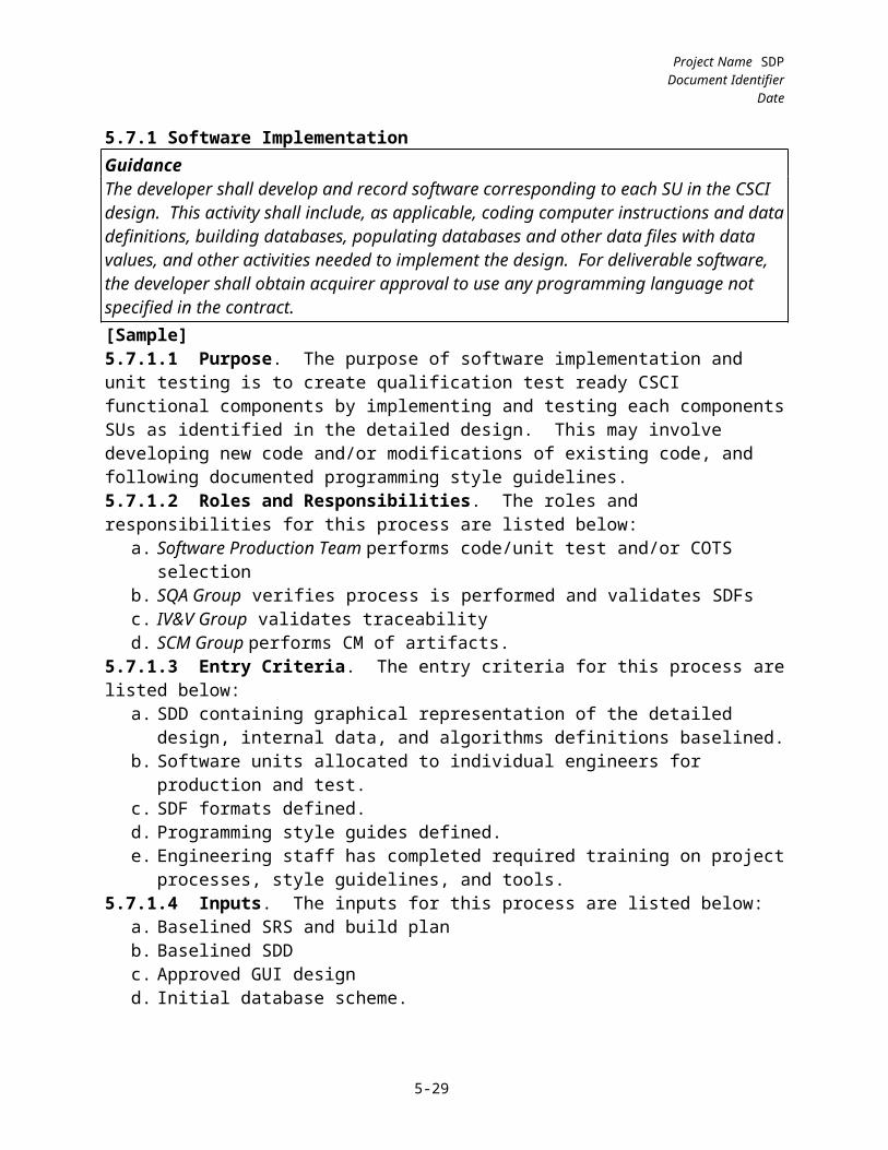
Project Name SDP Document Identifier
Date
Also refer to the SSC San Diego Software Quality Assurance (SQA) Process and the Software Quality Assurance Plan (SQAP) Template. Available from the SSC San Diego PAL.[Sample]The Software Quality Assurance Plan (SQAP), reference (g), is the guiding document for the conduct of SQA within the XY Project. [End Sample]
5.17 CORRECTIVE ACTIONGuidanceThis paragraph shall describe the approach to be followed for corrective action. The planning in each subparagraph shall cover all contractual clauses regarding the identified topic.[Sample]The XY Project will use the processes for databasing, tracking, and directing correction of P/CRs as defined the SCMP, reference (f). [End Sample]
5.18 JOINT TECHNICAL AND MANAGEMENT REVIEWSGuidanceThis paragraph shall describe the approach to be followed for joint technical and management reviews. The planning in each subparagraph shall cover all contractual clauses regarding the identified topic.Note: Also refer to the SSC San Diego “Keys to a Successful Meeting/Review” brief and the Software Management for Executives Guidebook. Available from the SSC San Diego PAL.[Sample]The purpose of technical and management reviews is to provide management with tracking and oversight of the progress of software development undertaken by the XY Project and fulfillment of requirements. Timely technical and management reviews at the appropriate level of detail facilitate information reporting and interchange that tracks progress against plans, identify and resolve action items, and verify appropriate expenditure of assigned resources. 5.18.1 Joint Technical ReviewsThe developer shall plan and participate in joint technical reviews at locations and dates proposed by the developer and approved by the acquirer. These reviews shall be attended by persons with technical knowledge of the software products to be reviewed. The reviews shall focus on in-process and final software products, rather than materials generated especially for the review. The reviews shall have the following objectives:
a. Review evolving software products, review and demonstrate proposed technical solutions; provide insight and obtain feedback on the technical effort; and surface and resolve technical issues.
b. Review project status and surface near and long-term risks regarding technical, cost, and schedule issues.
c. Arrive at agreed-upon mitigation strategies for identified risks, within the authority of those present.
d. Identify risks and issues to be raised at joint management reviews.e. Ensure ongoing communication between acquirer and developer technical personnel.
5-37

Project Name SDP Document IdentifierDate
5.18.2 Joint Management ReviewsThe Software Project Manager shall plan and participate in joint management reviews at locations and dates approved by the Program Manager. These reviews shall be attended by persons with authority to make cost and schedule decisions. The reviews will be scheduled in the MS Project Plan for the XY Project. Keep management informed about project status, directions being taken, technical agreements reached, and overall status of evolving software products. The objectives of management reviews are listed below:
a. Resolve issues that could not be resolved at joint technical reviews.b. Arrive at agreed-upon mitigation strategies for near and long-term risks that could not be
resolved at joint technical reviews.c. Identify and resolve management-level issues and risks not raised at joint technical
reviews.d. Obtain commitments and acquirer approvals needed for timely accomplishment of the
project.Given below is a set of candidate joint management reviews that might be held during a software development project. There is no intent to require these reviews or to preclude alternatives or combinations of these reviews.
a. Software plan reviews. These reviews are held to resolve open issues regarding one or more of the items listed below:1) Software Development Plan (SDP)2) Software Test Plan (STP)
b. Operational concept reviews. These reviews are held to resolve open issues regarding the operational concept for a software system.
c. System/subsystem requirements reviews. These reviews are held to resolve open issues regarding the specified requirements for a software system or subsystem.
d. System/subsystem design reviews. These reviews are held to resolve open issues regarding one or more of the items listed below:1) The system or subsystem-wide design decisions2) The architectural design of a software system or subsystem.
e. Software requirements reviews. These reviews are held to resolve open issues regarding the specified requirements for a CSCI.
f. Software design reviews. These reviews are held to resolve open issues regarding one or more of the items listed below:1) The CSCI-wide design decisions2) The architectural design of a CSCI3) The detailed design of a CSCI or portion thereof (such as a database).
g. Test readiness reviews. These reviews are held to resolve open issues regarding one or more of the items listed below:1) The status of the software test environment.2) The test cases and procedures to be used for CSCI qualification testing or system
qualification testing.3) The status of the software to be tested.
h. Test results reviews. These reviews are held to resolve open issues regarding the results of CSCI qualification testing or system qualification testing.
5-38

Project Name SDP Document Identifier
Date
i. Software usability reviews. These reviews are held to resolve open issues regarding one or more of the items listed below:1) The readiness of the software for installation at user sites2) The user and operator manuals3) The software version descriptions4) The status of installation preparations and activities.
j. Software supportability reviews. These reviews are held to resolve open issues regarding one or more of the items listed below:1) The readiness of the software for transition to the support agency.2) The software product specifications.3) The software support manuals.4) The software version descriptions.5) The status of transition preparations and activities, including transition of the
software development environment, if applicable.k. Critical requirement reviews. These reviews are held to resolve open issues regarding
the handling of critical requirements, such as those for safety, security, and privacy.[End Sample]
5.19 OTHER SOFTWARE DEVELOPMENT ACTIVITIESGuidanceThis paragraph shall describe the approach to be followed for other software development activities. The planning in each subparagraph shall cover all contractual clauses regarding the identified topic.[Sample]These paragraphs describe the technical and management approach to coordinating and providing oversight of software development activities undertaken by the XY Project. Timely technical and management oversight at the appropriate level is necessary to accomplish the activities listed below:
a. Track progress against plans b. Identify and resolve problems c. Identify and verify appropriate expenditure of assigned resources d. Depict activities and relationships associated with planning and conducting integration e. Consider other related development actions and schedules that could impact XY Project.
These paragraphs address those actions to be taken to maintain a broad management picture of XY Project software development.[End Sample]5.19.1 Risk ManagementGuidanceThe developer shall perform risk management throughout the software development process. The developer shall identify, analyze, and prioritize the areas of the software development project that involve potential technical, cost, or schedule risks; develop strategies for managing those risks; record the risks and strategies in the software development plan; and implement the strategies in accordance with the plan.Also refer to the Risk Management Process available from the SSC San Diego PAL.
5-39

Project Name SDP Document IdentifierDate
[Sample]Risk analysis and risk management deal with concerns of project personnel regarding the capability of the designed system to achieve program objectives of technical performance, schedule and cost. Risk analysis is an iterative process. It attempts to identify what could go wrong, plan courses of action to mitigate the occurrence, and plan contingencies in the event problems arise. Risk analysis identifies potential problem areas, quantifies risks associated with these problems, assesses the effect of these risks, and generates alternative actions/mitigations to reduce risks and recover from their occurrence.The major areas of risk for the software development will be managed following the process identified in the Risk Management Process, reference (i) [End Sample]5.19.2 Software Management IndicatorsGuidanceThe developer shall use software management indicators to aid in managing the software development process and communicating its status to the acquirer. The developer shall identify and define a set of software management indicators, including the data to be collected, the methods to be used to interpret and apply the data, and the planned reporting mechanism. The developer shall record this information in the software development plan and shall collect, interpret, apply, and report on those indicators as described in the planAlso refer to the Software Measurement Plan Template(SMP) available from the SSC San Diego PAL.[Sample]The XY Project management team will use software metrics for measurement of cost and schedule variance, productivity and quality. The XY Project measurement program is defined in the Software Measurement Plan (SMP), reference (h).[End Sample]5.19.3 Security and PrivacyGuidanceThe developer shall meet the security and privacy requirements specified in the contract. These requirements may affect the software development effort, the resulting software products, or both.[Sample]The XY Project software development is anticipated to contain a limited amount of classified data. Determination of classification will be in accordance with OPNAVINST S5513.3B, Security Classification Guide. Development of classified software will occur only in properly cleared spaces utilizing Automated Information Systems (AIS) approved computers. Transfer of classified programs between facilities shall utilize approved methods. The highest security level that should be encountered during software development is SECRET. Each software engineer or other software support person who requires access to classified material will be cleared to the appropriate level and supplied with an approved container in which classified material can be stored when not in use.[End Sample]5.19.4 Subcontractor ManagementGuidance
5-40

Project Name SDP Document Identifier
Date
If subcontractors are used, the developer shall include in subcontracts all contractual requirements necessary to ensure that software products are developed in accordance with prime contract requirements.Also refer to the SSC San Diego Contractor Acquisition and Monitoring (CAPM) Process. Available from the SSC San Diego PAL.[Sample]The Software Project Manager will use the SEPO-developed CAPM Process for Software Contracts as a guide for contractor management. The Software Project Manager will augment the CAPM by initiating additional management actions described below.Contractor personnel will participate in all development team activities including weekly status meetings, and informal and/or formal reviews as directed by Software Project Manager. Contractors will supply weekly measurements and monthly status reports on progress against their statement of work as called for in their individual Contract data requirements list (CDRLs).
When deemed necessary, the Software Project Manager will establish working groups made up of government and contractor personnel to address major project areas such as architecture, integration, and display. The Software Project Manager will also establish an overall XY Project software development, integration, and testing schedule. Included in this schedule will be all major project milestones that will enable a contractor to plan for delivery of their individual sections. To manage and track XY Project status/progress, the Software Project Manager will direct the use of the software management tool, Microsoft Project.[End Sample]5.19.5 Interface With Software Independent Verification and Validation (IV&V) AgentsGuidanceThe developer shall interface with the software Independent Verification and Validation (IV&V) agent(s) as specified in a tasking statement.[Sample]Coordination will be provided by having the IV&V Group participate/monitor activities in each phase of the development process including attending both formal and informal program reviews. In addition, the IV&V Group will be provided on-line access to source code, test scripts and documentation, and will participate in the SCCB.During all phases of software development, the IV&V Group will be able to initiate change requests to the evolving baseline or to add their review comments into the active action items to be resolved as a part of each end-of-phase review. These comments will be treated like any comment or change request initiated by a member of the project organization. Review comments are expected to be supplied in written form, or electronically in Microsoft Word, for subsequent tracking by the Software Project Manager in the same manner review actions items are handled. All comments will be adjudicated and responses provided back to the IV&V Manager describing the intended action to be taken. Change requests to change something in the developmental baseline, after the phase has been completed, will be entered into the configuration control system as described in SCMP and addressed like any other change request. The IV&V Group will be able to monitor the status of change requests they submitted directly from the SCM system.
5-41
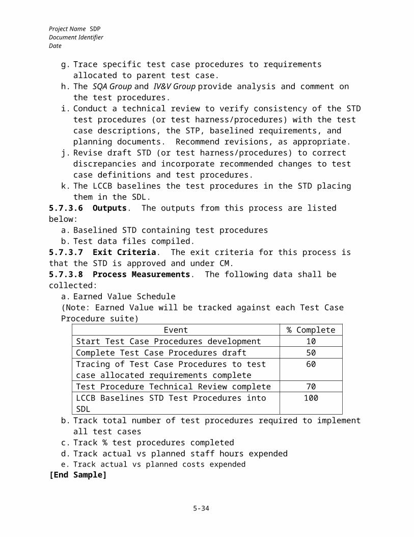
Project Name SDP Document IdentifierDate
[End Sample]5.19.6 Coordination With Associate DevelopersGuidanceThe developer shall coordinate with associate developers, working groups, and interface groups as specified in the contract.[Sample]The Software Project Manager and key staff members will meet weekly to clarify issues, obtain project status on deliverables, and elicit program comments. Updates will be provided and technical issues that affect the overall development effort will be discussed. In addition, the Software Project Manager will form sub-groups or committees to resolve complex technical and administrative issues. To provide a documentation trail, E-mail will be used as the primary means of distributing data amongst participants. [End Sample]5.19.7 Improvement of Project ProcessesGuidanceThe developer shall periodically assess the processes used on the project to determine their suitability and effectiveness. Based on these assessments, the developer shall identify any necessary and beneficial improvements to the process, shall identify these improvements to the acquirer in the form of proposed updates to the software development plan and, if approved, shall implement the improvements on the project.[Sample]As the XY Project program matures, the SDP should undergo revision reflecting improvements to the processes. Quality and process improvement comes by analyzing and measuring the process in a structured, controlled manner and then changing the process. These improvements should be the product of lessons learned data, findings of audits, and process measurements collected and fed back into the processes.The software development process described in this SDP generally follows MIL-STD-498. Where a process described in the SDP is deemed to be inadequate, cumbersome or non-responsive, any XY Project team member may submit a recommendation to change or improve that process. When compliance with specific software policies, processes, forms, or templates would impose severe impacts on project cost, schedule, resources, or customer relations, the implementing developer may request a waiver/deviation of specific provisions. They must propose reasonable and detailed alternatives during project planning. Requests for waivers/deviations must cite specific provisions of policies, processes, forms, or templates for which waivers/deviations are being requested, the impact of compliance, and alternatives to be implemented by the XY project.The Department Software Engineering Process Group (SEPG), interfacing with SEPO, shall be responsible for evaluating and acting upon suggestions for improvements in policies, processes, procedures, waivers/deviations, and standard forms and templates referenced in this SDP. In addition, process metrics collected during program development and lessons learned from this and other projects will be used to update the XY Project processes. The Software Project
5-42
Project Name SDP Document Identifier
Date
Manager is authorized to approve SEPG recommended changes to the XY Project processes described in the SDP. The Software Project Manager is responsible for post mortem analysis of each XY Project build to identify candidate processes for improvement and for the submission of Project Data Forms (PDF) to the Organization Software Process Database (OSPD) maintained by SEPO.[End Sample]
5-43

Project Name SDP Document IdentifierDate
This page intentionally left blank.
5-44

Project Name SDP Document Identifier
Date
SECTION 6. SCHEDULES AND ACTIVITY NETWORK
GuidanceThis section shall present the items listed below:
a. Schedule(s) identifying the activities in each build and showing initiation of each activity, availability of draft and final deliverables and other milestones, and completion of each activity. This can be created by using project management tools such as Microsoft Project.
b. An activity network, depicting sequential relationships and dependencies among activities and identifying those activities that impose the greatest time restrictions on the project. Activity networks
[Sample]The Program Office has established a Master Build Schedule as defined in Figure 6-1. The supporting WBS, cost, schedule, and staffing requirements for the Master Build Schedule is contained in Appendix A, the Microsoft Project Plan for the XY Project.
Figure 6-1. Master Build Schedule
[End Sample
6-1

Project Name SDP Document IdentifierDate
The page intentionally left blank.
6-2

Project Name SDP Document Identifier
Date
SECTION 7. PROJECT ORGANIZATION AND RESOURCES
GuidanceThis section shall be divided into the following sections to describe the project organization and resources to be applied in each build.[Sample]The XY Project and related organizations are described in Section 7.1. Staff requirements are tabularized in Section 7.2.[End Sample]
7.1 PROJECT ORGANIZATIONGuidanceThis paragraph shall describe the organizational structure to be used on the project, including the organizations involved, their relationships to one another, and the authority and responsibility of each organization for carrying out required activities. Below is an example organization chart for XY Project.[Sample]The XY Project Chain of Command and internal organization within SSC San Diego is depicted in Figure 7-1. The roles and responsibilities are contained in Table 7-1.
7-1

Project Name SDP Document IdentifierDate
Figure 7-1. XY Project Organizational Structure
7-2

Project Name SDP Document Identifier
Date
TABLE 7-1. ROLES AND RESPONSIBILITIES
POSITION ROLES/RESPONSIBILITIES
Sponsor OPNAV level organization providing Mission Element Need Statement (MENS) and DoN budget.
Program Office SYSCOM level organization tasked by OPNAV to perform system acquisition to meet MENS.
Program Manager SYSCOM level manager assigned responsibility to direct system acquisition (hardware/software).
Configuration Control Agent
SYSCOM level manager responsible for overall system configuration.
System CCB SYSCOM level configuration control board controlling the system configuration (hardware/software) a.k.a. SCCB.
Project A major component of a Program, can be either a hardware or software configuration item.
System Test Organization Organizational entity charged with system level acceptance testing. May, or may not, be at a separate geographic location but definitely has a separate chain of command.
System Test Manager Office within the System Test Organization charged with responsibility for system testing.
System Test Group Collective name of system test staff.System Test Engineer An individual in the System Test Group.Project Manager In this example, a SYSCOM level manager responsible to the
Program Manager for a project, both hardware and software configuration items. However, it should be noted that this responsibility may also be placed within an organization such as SSC San Diego.
Systems Engineering Manager
Manager responsible to the Program Manager for the overall system engineering. A candidate for the role of System CCB Chairperson.
Systems Engineering Group
System-level engineering staff, responsible for the system configuration (hardware/software) and the production and maintenance of the System Specification (i.e., SSS).
Systems Engineer Member of the Systems Engineering Group.Systems Engineering Requirements Team
Member of the Systems Engineering Group charged with specific responsibilities for managing the system requirement’s database.
Software Development/Maintenance Organization
Organizational entity, such as SSC San Diego, charged with system software development/maintenance.
Senior Management A senior manager (i.e., Executive Director, Department Head, or possibly a Division Head) providing infrastructure resources (i.e., facilities, admin., contracting, supply) to support an internal entity as a Software Development/Maintenance
7-3

Project Name SDP Document IdentifierDate
POSITION ROLES/RESPONSIBILITIES
Organization.Systems Engineering Process Office
SSC San Diego’s senior level entity providing process improvement direction.
Software Engineering Process Group
Professional staff providing Software Process Improvement (SPI) leadership to an SSC San Diego internal organization, such as a Division.
Software Project Manager An SSC San Diego ‘manager’ (i.e., a Division Head, or possibly Branch Head) responsible to the Project Manager for assigned software CSCIs. A candidate for LCCB chairperson.
Software Development Manager
An organizational line manager (i.e., a branch head or group leader), responsible for software development to the Software Project Manager.
Software Development Group
Collective name of the software engineering staff responsible for CSCI development.
Software Design Team Staff responsible for software architecture and design.Software Production Team Staff responsible for code, and/or reuse component selection,
and unit test.Software Requirements Team
Staff responsible for the software requirement’s database.
Software Test and Evaluation Manager
An organizational line manager (i.e., a branch head or group leader) responsible for CSCI and Integration Test and Evaluation to the Software Project Manager.
Software Test and Evaluation Group
Collective name of the software engineering staff responsible for CSCI integration and testing.
CSCI Test Team Software engineering staff responsible for Internal CSCI Testing.
Integration Test Team Software engineering staff responsible for Internal CSCI/HWCI Testing.
Delivery Team Software engineering staff responsible for on site deliveries, training, and testing.
SCM Manager An organizational line manager (i.e., a branch head or group leader) responsible for Software Configuration Management (SCM) to the Software Project Manager.
SCM Group Collective name of the software engineering staff responsible for SCM functions.
Documentation Team Staff responsible for production and maintenance of project documentation, such as software specifications (i.e., SRS) and users manuals.
Librarian Member of engineering staff who is keeper of document and program baselines (check in/out)
SQA Manager An organizational line manager (i.e., a branch head or group leader), responsible for Software Quality Assurance (SQA)
7-4
Project Name SDP Document Identifier
Date
POSITION ROLES/RESPONSIBILITIES
functions who reports to the Software Project Manager.SQA Group Collective name of the software engineering staff responsible
for SQA functions.IV&V Organization Program Level organization charged with the responsibility of
providing resources and management for IV&V functions. Most often organized such that they report to the Program Manager, typically an organizational entity with a chain of command separate from SSC San Diego’s.
IV&V Manager Office within the IV&V Organization charged with responsibility for IV&V functions.
IV&V Group Collective name of IV&V staff.[End Sample]
7.2 PROJECT RESOURCESGuidanceThis paragraph shall describe the resources to be applied to the project. It shall include, as applicable, those listed below:
a. Personnel resources, including:1) The estimated staff-loading for the project (number of personnel over time).2) The breakdown of the staff-loading numbers by responsibility (for example,
management, software engineering, software testing, software configuration management, software product evaluation, software quality assurance).
3) A breakdown of the skill levels, geographic locations, and security clearances of personnel performing each responsibility.
b. Overview of developer facilities to be used, including geographic locations in which the work will be performed, facilities to be used, and secure areas and other features of the facilities as applicable to the contracted effort.
c. Acquirer-furnished equipment, software, services, documentation, data, and facilities required for the contracted effort. A schedule detailing when these items will be needed shall also be included.
d. Other required resources, including a plan for obtaining the resources, dates needed, and availability of each resource item.
An example of a staffing plan is given in Table 7-2.[Sample]Table 7-2 provides a breakdown of personnel requirements required by the XY Project to support development of the system software from Build 1 through Build 3 as illustrated in Figure 6-1. These resources have been allocated to the MS Project Plan contained in Appendix A.
TABLE 7-2. PERSONNEL REQUIREMENTS (PERSON YRS)Activity
PersonnelSystem Rqmts Analysis/Desig
n
Detailed Design
Code and Unit Test
System Integration Subtotals
Management 1 2 2 1 6
7-5

Project Name SDP Document IdentifierDate
Systems Engineer
5 3 2 1 11
Hardware 3 2 2 1 8S/W Engineer 5 10 15 3 33CM 2 2 4 2 10SQA 1 1 2 1 5Testing 1 2 1 5 9IV&V 1 2 2 4 9Facilities 1 1 2 2 6ILS 1 1 2 2 6Subtotals 21 26 34 22 (Total) 103
[End Sample]
7-6

Project Name SDP Document Identifier
Date
SECTION 8. NOTES
GuidanceThis section shall contain any general information that aids in understanding this document (e.g., background information, glossary, and rationale). This section shall include an alphabetical listing of all acronyms, abbreviations, and their meanings as used in this document and a list of any terms and definitions needed to understand this document.
8.1 ACRONYMSGuidanceAlphabetically list all acronyms used in this document.[Sample]
AIS Automated Information SystemAWG Architecture Working GroupBCC Black Controller CSCICAPM Contractor Acquisition and Performance MonitoringCASE Computer-Aided Software EngineeringCC Configuration ControlCDRL Contract Data Requirements ListCI Configuration ItemCM Configuration ManagementCM Capability Maturity ModelCOM Computer Operation ManualCOTS Commercial Off-the-ShelfCPM Computer Programming ManualCR Change ReportCSAR Configuration Status Accounting ReportCSCI Computer Software Configuration ItemDBDD Database Design DescriptionDCR Document Change RequestDDR Detailed Design ReviewDID Data Item DescriptionDoD Department of DefenseDoDI Department of Defense InstructionDoN Department of NavyECP Engineering Change ProposalFOT Functional Operability TestingFQT Formal Qualification TestFSM Firmware Support ManualFST Functional Stress TestingGOTS Government Off-the-ShelfGUI Graphical User InterfaceHCI Human Computer Interface
8-1

Project Name SDP Document IdentifierDate
HWCI Hardware Configuration ItemIDD Interface Design DescriptionIEEE Institute of Electronics and Electrical EngineersILS Integrated Logistics SupportIMT Interface Message TestsIRS Interface Requirements SpecificationIRT Interface Recovery TestsIST Interface Stress TestsIVT Interface Validation TestsIV&V Independent Verification and ValidationKM Cryptographic ModuleKPA Key Process AreaLCCB Local Software Configuration Control BoardLCM Life Cycle MaintenanceMENS Mission Element Needs StatementMTP Master Test PlanNDI Non-Developmental ItemOCD Operational Concept DescriptionOOD Object-Oriented DesignOPEVAL Operational EvaluationPAL Process Asset LibraryPAT Program Acceptance TestPP Program PackagePPI Pre Planned Product ImprovementPR Problem ReportPSM Practical Software MeasurementPTR Program Trouble ReportQA Quality AssuranceRAM Reuse Adaptation and ManagementRBC Red/Black ControllerRCC Red Controller CSCIRM Requirements ManagementR&R Review and ResponseRT Regression TestSCCB System Configuration Control BoardSCM Software Configuration ManagementSCMP Software Configuration Management PlanSCOM Software Center Operator ManualSDD Software Design DescriptionSDF Software Development FileSDL Software Development LibrarySDP Software Development PlanSEE Software Engineering EnvironmentSEI Software Engineering InstituteSEN Software Engineering Notebook
8-2

Project Name SDP Document Identifier
Date
SEPG Software Engineering Process GroupSEPO System Engineering Process OfficeSIOM Software Input/Output ManualSIP Software Installation PlanSMP Software Measurement PlanSOW Statement of WorkSPA Software Process Assets documentSPE Software Product EvaluationSPI Software Process ImprovementSPIP Software Process Improvement PlanSPM Software Project ManagerSPP Software Project PlanningSPS Software Product SpecificationSPTO Software Project Tracking and OversightSQA Software Quality AssuranceSQAP Software Quality Assurance PlanSQER Software Quality Evaluation ReportSQT System Qualification TestSRS Software Requirements SpecificationSSC SPAWAR Systems Center San DiegoSSDD System/Subsystem Design DescriptionSSS System/Subsystem SpecificationSTD Software Test DescriptionSTE Software Test EnvironmentSTP Software Test PlanSTR Software Test ReportSTrP Software Transition PlanSU Software UnitSUM Software User ManualSVD Software Version DescriptionSW SoftwareSYSCOM System CommandTECHEVAL Technical EvaluationTD System level test descriptionTP System level test planTRR Test Readiness ReviewWBS Work Breakdown Structure
[End Sample]
8-3

Project Name SDP Document Identifier
Date
APPENDIX A. PROJECT PLAN
GuidanceAppendices may be used to provide information published separately for convenience in document maintenance (e.g., charts and classified data). As applicable, each appendix shall be referenced in the main body of the document where the data would normally have been provided. Appendices may be bound as separate documents for ease in handling. Appendixes shall be lettered alphabetically (A, B, C…).
[Sample]<XY Project Microsoft Project Plan> [End Sample]
A-1

Project Name SDP Document IdentifierDate
This page intentionally left blank.
A-2

DOCUMENT CHANGE REQUEST (DCR)Document Title: Project Name Software Development Plan Tracking Number:
Name of Submitting Organization:
Organization Contact: Phone:
Mailing Address:
DCR Description: Date:
Change Location: (use section #, figure #, table #, etc.)Proposed change:
Rationale for Change:
Note: For the <indicate appropriate authority> to take appropriate action on a change request, please provide a clear description of the recommended change along with supporting rationale.Send to: Commanding Officer, Space and Naval Warfare Systems Center, Code [[2xx]], 53560 Hull Street, San Diego, CA 92152-5001 Fax to: <indicate appropriate fax number>Email to: <indicate appropriate email>Submit online: <indicate appropriate URL>
DCR Form 2/2005