Embed Size (px)
DESCRIPTION
Citation preview

Software Architecture-based Regression Testing
Henry Muccinia, Marcio Diasb, Debra J. Richardsonc
aDipartimento di Informatica,University of L’Aquila, L’Aquila, Italy, email: [email protected]
bDept. of Computer Science and e-Science Research Institute,University of Durham, Durham, UK, email: [email protected]
cDept. of Informatics, Donald Bren School of Information and Computer Sciences,University of California Irvine, USA, email: [email protected]
Abstract
Software architectures are becoming centric to the development of quality software sys-tems, being the first concrete model of the software system and the base to guide the im-plementation of software systems. When architecting dependable systems, in addition toimproving system dependability by means of construction (fault-tolerant and redundantmechanisms, for instance), it is also important to evaluate, and thereby confirm, system de-pendability. There are many different approaches for evaluating system dependability, andtesting has been always an important one, being fault removal one of the means to achievedependable systems.
Previous work on software architecture-based testing has shown it is possible to applyconformance testing techniques to yield some confidence on the implemented system con-formance to expected, architecture-level, behaviors.
This work explores how regression testing can be systematically applied at the softwarearchitecture level in order to reduce the cost of retesting modified systems, and also toassess the regression testability of the evolved system. We consider assessing both “low-level” and “high-level” evolution, i.e., whether a slightly modified implementation con-forms to the initial architecture, and whether the implementation continues to conform toan evolved architecture. A better understanding on how regression testing can be applied atthe software architecture level will help us to assess and identify architecture with higherdependability.
Key words:Software Architecture, Dependable Systems, Regression Testing, Architecture-basedAnalysis and Testing.1
1 Main acronyms: SA = Software Architecture, RT = Regression Testing, TS = TransitionSystem, ATS = Abstract TS, ATC = Architecture-level Test Case, GP = program Graph.
Preprint submitted to Elsevier Science 9 February 2006

1 Introduction
A Software Architecture (SA) [16] specification captures system structure (i.e., thearchitectural topology), by identifying architectural components and connectors,and required system behavior, designed to meet system requirements, by specify-ing how components and connectors are intended to interact. Software architecturescan serve as useful high-level “blueprints” to guide the production of lower-levelsystem designs and implementations, and later on for guidance in maintenance andreuse activities. Moreover, SA-based analysis methods provide several value addedbenefits, such as system deadlock detection, performance analysis, component val-idation and much more [6]. Additionally, SA-based testing methods are available tocheck conformance of the implementation’s behavior with SA-level specificationsof expected behavior [13] and to guide integration and conformance testing [7,28].
Reaping these architectural benefits, however, does not come for free. To the con-trary, experience indicates that dealing with software architectures is often expen-sive perhaps even too expensive, in some cases, to justify the benefits obtained.For example, consider the phenomenon of “architectural drift” [34]. It is not un-common during evolution that only the low-level design and implementation arechanged to meet tight deadlines, and the architecture is not updated to track thechanges being made to the implementation. Once the architecture “drifts” out ofconformance with the implementation, many of the aforementioned benefits arelost: previous analysis results cannot be extended or reused, and the effort spenton the previous architecture is wasted. Moreover, even when implementation andarchitecture are kept aligned, SA-based analysis methods often need to be reruncompletely from the beginning, at considerable cost, whenever the system archi-tecture or its implementation change. SARTE (Software Architecture-based Re-gression TEsting) is a collaborative project among the three authors universitiesfocused on providing a framework and approach for SA-based testing in the con-text of evolution, when both architecture and implementation are subject to change.The topic of architecture-based testing has been extensively analyzed by one of theauthors in [28], where a general framework for software architecture-based confor-mance testing has been proposed. A software architecture-based testing and analy-sis toolset (Argus-I) was developed by two of the authors, as described in [13].
SARTE builds upon the research and development in both previous projects. In thiscontext, this paper shows how SA-based regression testing provides a key solutionto the problem of retesting an SA after its evolution. In particular, after identifyingSA-level behavioral test cases and testing conformance of the code with respectto the expected architectural behaviors [28], we show what should be tested whenthe code and/or architecture is modified and how testing information previouslycollected may be reused to test the conformance of the revised implementation withrespect to either the initial or revised architecture. We describe, in general terms,i) how implementation-level test cases may be reused to test the conformance of
2

modified code with respect to the architectural specification, andii) how to reusearchitecture-level test cases when the architecture evolves. Our approach relies onreusing and modifying existing code-level regression testing (RT) techniques.
1.1 Motivations and Goals
This section describes why SA-based RT can contribute to improve the overallsystem dependability (Section 1.1.1) and our ongoing project goals (Section 1.1.2).
1.1.1 SARTE Motivations
Regression testing permits to test modified software to provide confidence that nonew errors are introduced into previously tested code. It may be used duringde-velopment, to test families of similar products, or duringmaintenance, to test newor modified configurations [19]. Although SA-based RT may be used for both pur-poses, we here focus on the maintenance aspect, being confident this approach maybe used during development as well.
In this section we analyzei) why a software architecture may change due to main-tenance or evolution, andii) why regression testing at the architecture level is arelevant topic.
Why may Software Architectures change?
Software architectures may change over time, due to the need to provide a more de-pendable system, the need to remove identified deficiencies, or the need to handledynamically-evolving collections of components at runtime [16]. Much researchhas investigated SA evolution, especially at runtime. In [32], for example, the au-thors analyze how an architecture may change at runtime (in terms of componentaddition, component removal, component replacement, and runtime reconfigura-tion) and how tool suites may be used to cope with such evolution. In [4] theauthors describe an approach to specify architectures that permits the represen-tation and analysis of dynamic architectures. In [24] the authors analyze the issuesof dynamic changes to a software configuration, in terms of component creationand deletion, and connection and disconnection. In [27] the authors analyze suchArchitecture Description Languages which provide specific features for modelingdynamic changes.
Why SA-based Regression Testing?
Many functional and non-functional analysis techniques have been proposed to op-
3

erate at the SA-level [6]. However, the drawback is that (given that an architecturemay evolve) current techniques require that SA-based analysis becompletely re-run from scratchfor a modified SA version, thereby increasing analysis costs andreducing benefits. To mitigate this drawback, we propose here to apply regressiontesting at the SA level in order to lower the cost and greatly improve the cost-benefitproperties of SA-based testing.
The benefits we expect are manifold:i) the selection of SA-level test cases and theirexecution at the code level is a long and expensive process (as described in [28]and summarized in Section 3.1). Reusing previous results as much as possible maystrongly reduce testing effort while testing a modified architecture. Quoting [18],in fact, “regression testing can account for as much as one-third of the total costof a software system... the use of software architecture for regression testing activ-ities has the potential for a bigger impact on the cost of software”;ii) SA-basedtesting can identify (functional) errors that are likely to be missed when applyingtraditional code-level testing, thus complementing traditional testing techniques. Inline with research on specification-based RT (see Section 6), SA-based RT mayvaluably complement code-based RT, as discussed later in Section 5.
1.1.2 SARTE Goals
SARTE’s intermediateproject goalsare depicted in Figure 1, where the left sideembodies our first goal and the right side embodies the second goal:
Goal 1: Test Conformance of a Modified Implementation P′ to the initial SA.
• Context: Given a software system, an architecture S, and an implementation P,we first gain confidence thatP correctly implements S. During maintenance, amodified version of the code (P′) is implemented - where some componentsfrom P remain, some components are modified, and/or some new componentsare introduced.
• Goal: Test the conformance of P′ with respect to S, while reusing previous testinformation for selective regression testing, thereby reducing the test cases thatmust be retested.
Goal 2: Test Conformance of an Evolved Software Architecture.
• Context: Given a software system, an architecture S, and an implementationP, we have already gained confidence that P correctly implements S. Supposeevolution requires a modified version of the architecture (S′′) - where somearchitecture-level components are kept, others are modified, and/or new onesare introduced and consequently a modified implementation P′′ may have beenalso developed.
• Goal: Test the conformance of P′′ with respect to S′′, while reusing previous
4

Component A Component C
Architectural Test Cases
(ATCs) are extracted to
test the source code
Component B
Component A Component C’
Component Y
The
code
evolves
Goal1: Test
the new code
conformance
to S
P (Code, version 1)
P’ (Code, version 2)
T h e S A
e v o l v e s
Goal2: Test
S’’ and code,
reusing
previous
results
The code
may evolve
P’’
Software Architecture S
(version 1) Software Architecture S’’
(version 2)
a) b)
Component B
Fig. 1. Project goals:a) the implementation evolves;b) the software architecture evolves
test information for selective RT, thereby reducing the test cases that must beretested.
In the rest of this paper we address both goals, by proposing an approach to inte-grate existing code-level RT techniques with SA-based RT and by exploiting simi-larities and differences between SA versions.
A different goal is to reconstruct the actual architecture when the first goal deter-mines that the code no longer conforms to the initial architecture. This is a sort ofreverse-engineering activity that could mitigate the architectural drift problem in amore general context. Ongoing research on this topic is presented in Section 7.
1.2 Paper Structure and Organization
The paper is organized as follows. Basic background on regression testing is pro-vided in Section 2. A theoretical description of the approach is presented in Sec-tion 3. In Section 4 we illustrate the application of SARTE to two different appli-cations: the Elevator example and the Cargo Router system. Section 5 provides adescription of what we learned from our experience on SA-based regression testingtogether with some considerations. Related work are briefly discussed in Section 6.The paper concludes with a discussion on ongoing and future work (Section 7) andsome concluding remarks (Section 8).
5

2 Regression Testing
In this section, we focus on the regression testing strategy to provide the back-ground necessary to understand our approach for SA-based regression testing. Webriefly introduce how regression testing works, describing, in broad terms, how toidentify appropriate tests in a regression test selection context.
Regression testing, as quoted from [19], “attempts to validate modified softwareand ensure that no new errors are introduced into previously tested code”. Thetraditional approach is decomposed into two key phases:i) testing the program Pwith respect to a specified test suite T, andii) when a new version P′ is released,regression testing of the modified version P′ to provide confidence that P′ is correctwith respect to a test set T′.
To explain how a regression testing technique works in general, let us assume thata program P has been tested with respect to a test set T. When a new version P′
is released, regression testing techniques provide a certain confidence that P′ iscorrect with respect to a test set T′. In the simplest regression testing technique,calledretest all, T′ contains all the test cases in T, and P′ is run on T′. In selectiveregression testing, T′ is selected as a “relevant” subset of T, wheret ∈ T is relevantfor P′ if there is the potential that it could produce different results on P′ that it didon P (following asafedefinition).
In general terms and assuming that P is a program under test, T a test suite forP, P′ a modified version of P and T′ the new test suite for P′, regression testingtechniques work according to the following steps:1) select T′, subset of T andrelevant for P′; 2) test P′ with respect to T′; 3) if necessary, create T′′, to test newfunctionality/structure in P′; 4) test P′ with respect to T′′; 5) create T′′′, a new testsuite and test history.
All of these steps are important for the success of a selective regression testingtechnique and each of them involves important problems [17]. However, step1(also called, regression test selection) characterizes a selective regression testingtechnique. For this reason, we focus on this step to propose an SA-based regressiontesting approach in the rest of this paper.
3 SARTE: SA-based Regression Testing
Our SA-based regression testing inherits the two-phased decomposition from tra-ditional RT approaches, and comprises the following two phases:
SA-based conformance testing. We apply a SA-based conformance testing approach.
6

Step 0
SA-spec S
Testing Criterion
Map ATCs into Code-level
Test Cases as a way to select T for P
Extract SA-level
Test Cases (ATCs)
Run T over P and Evaluate Results
Step 1
Step 2
Step 3
Step 4
Build the GP graph for P
Build the GP’ graph for P’
Compare GP with GP’
Create a Test History
Select T' for P'
SA-based
Regression Testing
- Goal 1 -
SA-based Conformance
Testing
SA-spec S’’
Compare S and S’’
Select ATCs’’ from S that need
to be retested in S’’
Map ATCs’’ into Code-level Test
Cases as a way to select T’’ for P’’
Run T’’ over P’’ and Evaluate Results
SA-based
Regression Testing
- Goal 2 -
Step B
Step C
Step D
Step a
Step c
Step d
Step e
Step f
Step A
Testing Criterion
Step b
Fig. 2. Activity Diagram of our SA-based Regression Testing approach
SA-based regression test selection. This phase is decomposed to meetGoal 1andGoal 2 in Section 1.1.2.
Figure 2 summarizes the activities required by SA-based conformance and re-gression testing. While SA-based conformance testing has been already analyzedin [28,29], goal of this paper is to focus on SA-based regression testing.
3.1 SA-based Conformance Testing
As mentioned before, this work builds upon the general framework for SA-basedconformance testing set forth in [28], whose goal is to test the implementation con-formance to a given software architecture. The software architecture specification isused as a reference model to generate test cases while its behavioral model, whichdescribes the expected behavior, serves as a test oracle.
The framework encompasses five different steps, as shown in the middle section ofFigure 2.
Step 0: SA specification.It begins with a topological and behavioral specification ofthe SA. The topology describes the SA structure in terms of components, connec-tors, and configuration. The behavioral model specifies how the SA is supposed tobehave. Architecture description languages are employed for topological descrip-tion, while transition systems (TS) are hereafter employed for SA behavior.
Step 1: Testing criterion.An observation function is introduced in order to imple-ment atesting criterionthat looks at the SA from a perspective that is deemed to
7

be relevant for testing purposes, while hiding away non-relevant actions from thisperspective. The state machine-based model is abstracted, producing an AbstractTS (ATS), in order to show such high-level behaviors/components we want to test.
Step 2: Architecture-level test case.An architecture-level test case (ATC) is definedasan ordered sequence of architectural events we expect to observe when a certaininitiating event is performed. This definition encompasses two different keywords:the sequence of actions, which represents expected behaviors, and the initiatingevent, that is, the architectural input which should allow the sequence to happen.Deriving an adequate set of ATCs entails deriving a set of complete paths thatappropriately cover the ATS.
Step 3: Test cases.Naturally, such ATCs strongly differ from executable code-leveltest cases, due to the abstraction gap between software architecture and code (thetraceability problem[14]). We deal with this problem through a “mapping” func-tion which maps SA-level functional tests into code-level test cases.
Step 4: Test execution.Finally, the code is run over the identified test cases. Theexecution traces are analyzed to determine whether the system implementationworks correctly for the selected architectural tests, using the architectural behav-ioral model as a test oracle to identify when a test case fails or succeeds.
Experience on applying SA-based conformance testing has demonstrated its fea-sibility and suitability. However, repeating the entire testing process at any timethe system evolves is undoubtedly too expensive, thus making SA-based testingless appealing and applicable. Here we propose an approach to deal with sys-tem evolution, which reuses previous test results to retest the modified architec-ture/implementation with reduced effort.
3.2 Goal 1: Test Conformance of a Modified Implementation P′ to the initial SA
Let us assume SA-based conformance testing has provided confidence that the im-plementation P conforms to a given SA. After evolving P to P′ (Figure 1.a), andassuming the same architectural decisions want to be implemented, how can wetest the conformance of P′ to the same architecture?
The approach we take here is based on the idea of integrating SA-based testing tech-niques with existing code-based RT techniques. Figure 2 (right side) summarizes,through an activity diagram, how code-level RT may be integrated with SA-levelconformance testing to select a new test suite T′:
Step A: Generating P graph (GP).Most common approaches to code regressiontesting is to structurally represent P using a graph. Depending on the selective re-gression testing technique, this graph can be a control flow graph, a control depen-
8

dence graph, a program dependence graph and so on. After modification, P′ is alsorepresented as a graph.
Step B: Comparing GP with GP′. As in traditional code-based regression testing,the code graphs for P and P′ are compared, to identify how code changes are re-flected in the graph. Notice we are not restricted to any specific graph represen-tation or graph comparison technique. As we will show later in Section 4, in ourexperimental studies, we used different technologies to this end.
Step C: Recording Coverage.P is executed over eacht ∈ T. (We remind that a testsuite T for P has been already identified during the SA-based conformance testingphase – Step 3 in Figure 2). During execution, information on how the graph istraversed is recorded, usually produced by light code instrumentation. For each testcaset, the Test History keeps track of the nodes and arcs in GP traversed whileexecuting P overt.
Step D: Test Case Selection for P′. The information gathered from the test historyand the graph comparison is used to identify test cases in T to be rerun on P′. Ifexecution of P ont ∈ T might cover a node which is modified in P′, thent needs tobe rerun on P′.
Once T′ is selected,t′ ∈ T′ is run over P′ and results are collected and comparedwith an oracle to decide if the test failed or succeeded.
While those steps are those traditionally considered for regression testing, one ofthe main differences with respect to traditional code-based RT techniques is thatthe oraclein SA-based RTis the software architecture specification itself(as hap-pens in specification-based regression testing). In fact, whent′ is run on P′, the testfails if its execution does not allow the expected behavior to be reproduced (i.e.,the architecture-level test case associated tot′). Moreover, code-level test cases arealways driven by well formalized functional and structural architectural require-ments. The advantages we expect from this approach are twofold:i) as in traditionalRT, we reduce the size of the test suite for P′, eliminating all those tests which donot need to be reapplied to P′, andii) when conformance faults are detected, wecan gather information on how to adjust the initial architecture (initial results onthis topic will be presented in Section 7).
3.3 Goal 2: Test Conformance of an Evolved Software Architecture
Let us assume again that SA-based conformance testing has demonstrated that im-plementation P conforms to a given SA. After evolving S into S′′ (Figure 1.b) howcan we test the implementation’s conformance to the new architecture?
The approach we take here is based on the idea of comparing the two architectural
9

specifications to identify changed/unchanged portions of the SA. Both structuraland behavioral changes are taken into account.
Figure 2 (left most side) summarizes how Goal 2 may be realized through differentactivities:
Step a: New SA specification.The architectural specification of the evolved systemS′′ is provided in terms of structural and behavioral models. A graph representinghow the SA behaves is obtained by composing the TS models of component behav-ior, following the structural organization of those components in the architecture.
Step b: Testing Criterion.The testing criterion (previously identified in the confor-mance testing phase, step 1, and applied to S) is applied to S′′.
Step c: Comparison.The architectural specifications are compared to identify topo-logical changes and behavioral changes (i.e., added, removed or modified compo-nents).
Topological changes are identified by comparing the two versions of the structuralspecification provided in some architectural language. Added or deleted compo-nents or modified configurations can be revealed by this analysis. However, struc-tural comparison is certainly not enough, since the same topological description canlead to differently behaving architectures. Behavioral changes are identified basedon differences in ATS nodes and edges.
An SA diffalgorithm is used to compare the two behavioral specifications S and S′′
and differences are identified.
Notice that the “comparison” step is executed over the ATSs (instead directly to theTS specifications) since we are interested to test the two specifications with respectto the same testing criterion.
Step d: Select Architectural Test Cases for S′′. Those ATCs that were affected byarchitectural changes are selected to be retested in the S′′ implementation. Noticethat any ATC discarded in this step may represent many code-level test cases thatwere eliminated, thus strongly reducing re-testing effort.
Step e: Identify Code-Level Test Cases. Once we have identified the ATCs whichneed to be regression tested in S′′, we map these architectural test cases to code-level test cases for S′′, in order to select T′′ for P′′. This step is analogous to Step 3in SA-based testing.
Step f: Test Execution. After T′′ has been selected for S′′, we need to run T′′ overP′′ and evaluate the result of the performed SA-based regression testing. This stepis analogous to Step 4 in SA-based testing.
10

In order to gain some practical experience on the topic, in the following we spe-cialize and refine some of the activities in Figure 2 to some examples.
4 Application of SARTE to Case Studies
In this section, we present our software architecture-based regression testing ap-proach being applied into two different case studies: the Elevator example (Sec-tion 4.1) and the Cargo Router system (Section 4.2). For sake of brevity, we discussonly the application of Goal 1 to the Elevator case study and of Goal 2 to the CargoRouter system, and then we summarize the other results.
Since how to perform the SA-based conformance testing phase described in Sec-tion 3.1 has been already discussed elsewhere [28], we limit the discussion on howto identify SA-based test cases, while leaving more space for Goal 1 and Goal 2.
An evaluation of the overall results is presented in Section 4.3.
4.1 Elevator Example
Elevator systems have been widely used in testing and analysis literature becauseof two main reasons:i) everyone is familiar with elevator systems, and can easilyunderstand the requirements for such application domain, andii) these systemscontain stateful components and timing requirements, which give them a level ofcomplexity that is interesting for verification purposes.
In this section, we illustrate the application of our technique to an Elevator systemwhose architectural specification follows the C2 architectural style [2]2 . We havepreviously performed the SA-based conformance testing technique over this sys-tem, as reported in [29]. Now, going through this example, we illustrate how Goals1 and 2 are accomplished in our SA-based regression testing technique.
We use two different configurations for the elevator system. Our first configura-tion (representing S) contains the building panel (which includes all the panelsfrom different floors of the building) and one elevator car (Figure 3.b). Our sec-ond configuration (representing S′′) contains the building panel, two elevator cars,and a scheduler component which assigns calls requested through the building tothe closest elevator car (Figure 3.c). In detail, the components for these elevatorsystems are:
2 The C2 style imposes some composition and behavioral rules enabling some level of in-dependence between the components used to describe the SA. Communication may happenonly through connectors. Communication is message based.
11

ElevatorPanel1
Scheduler
BuildingPanel
ElevatorPanel2
C2 connector
C2 component
comm. channel
ElevatorADT1 ElevatorADT2
ElevatorPanel1
BuildingPanel
ElevatorADT1
Elevator System, Version 1
(S)
Elevator System, Version 2
(S ’’ )
a)
b)
c)
Fig. 3. The Elevator systems:a) GUI, b) architecture of the first elevator configuration (S),c) architecture of the second system configuration (S′′)
• BuildingPanel: this component represents all the elevator call panels of thebuilding. Through this component, users in different floors can request a call tothe elevator system, indicating the desired direction.
• Scheduler: this component receives call requests from the BuildingPanel,and selects which elevator should attend such call. In our case study we are usinga scheduling policy so that if a call is made at time “t”, it selects the elevator carthat, at time “t”, could attend it with the lower waiting time required.
• ElevatorPanel: this component represents the internal panel of an elevatorcar. After entering the elevator, the passenger can request calls through it and seethe current floor.
• ElevatorADT: this component maintains the information about the elevatorcar state, and a list of all the calls it needs to attend.
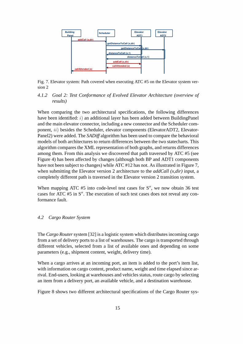
When applying SA-based conformance testing over the Elevator system, we mod-eled components transition systems using statecharts, with the semantics describedin [12]. Each component has its behavior described with statecharts, and the ar-chitecture configuration combines those statecharts in order to produce a globalarchitectural behavioral model [12]. From the global model, we applied a testingcriterion in order to select as “relevant” all, and only, such messages necessary tosend a call (theaddCall) and to receive thecallAttendedmessage (which meansthat the call has been handled), while hiding the others. Twenty four ATCs havebeen selected corresponding to the testing criterion. Two of them are analyzed inthis paper, and shown in Figure 4.
In ATC #5, the test scenario is given by the elevator (ADT1) attending a call placedin the building panel (BP). In other words, BP sends an addCall and ADT1 attendsthe call and replies with a callAttended message. In ATC #12, the test scenariois given by the elevator attending a call placed in its internal panel. From thosetwo ATCs, 18 (code-level) test cases have been generated (shown in Figure 5) byapplying the test selection technique in [29].
The code level test cases have been run on the system implementation and no errors
12

Building
Panel
Elevator
ADT1
addCall (x,dir)
callAttended (x)
Architectural Test Case ATC #5 (SA1):
BP sends Call; ADT1 attends Call
Elevator
Panel1
Elevator
ADT1
addCall (x)
callAttended (x)
Architectural Test Case ATC #12 (SA1):
EP1 sends Call; ADT1 attends Call
Fig. 4. Elevator system: Architectural Test Cases ATC #5 and ATC #12 for S
TC1: BP. addCall (1,up); ADT1(1,up) TC2: BP. addCall (1,up); ADT1(2,up) TC3: BP. addCall (1,up); ADT1(2,down) TC4: BP. addCall (2,up); ADT1(1,up) TC5: BP. addCall (2,up); ADT1(2,down) TC6: BP. addCall (2,up); ADT1(3,down) TC7: BP. addCall (2,down); ADT1(1,up) TC8: BP. addCall (2,down); ADT1(2,up) TC9: BP. addCall (2,down); ADT1(3,up) TC10: BP. addCall (3,down); ADT1(4,down) TC11: BP. addCall (3,down); ADT1(3,down) TC12: BP. addCall (3,down); ADT1(2,down)
TC1: EP1. addCall (1); ADT1(1,up) TC2: EP1. addCall (1); ADT1(2,up) TC3: EP1. addCall (1); ADT1(2,down) TC4: EP1. addCall (2); ADT1(1,up) TC5: EP1. addCall (2); ADT1(2,down) TC6: EP1. addCall (3); ADT1(2,down)
Path #1 – Test Cases
Path #2 – Test Cases
Fig. 5. Elevator system: Test cases derived from ATC #5 and ATC #12
have been revealed. More details on the Elevator architectural specification and testcase selection can be found in [29] (even if there we used a different notation tospecify the SA behavior).
4.1.1 Goal 1: Test Conformance of P′ to the Elevator architecture, version 2
Taking into consideration the Elevator system architecture, version 2 (showed inFigure 3.c) and by submitting its implementation (version ElevatorArch5) to aninformal, runtime analysis, we realized the algorithm used to assign calls to theelevators was not optimal. The initial algorithm assigns a call to elevator X, when attime “t” such elevator can attend the call with the lower waiting time. Unfortunately,if at time “t+1” other calls (internal or external) are made, we are not anymoreguaranteed on the optimality. We thus decided to change the algorithm, and thecode itself, in order to provide a more flexible (runtime) way to assign calls.
ElevatorArch5B version has been produced for this goal. Moreover, we produceda third version ElevatorArch5C, injecting a fault in the ElevatorArch5B version. Inthe following, we will refer to those versions as v5, v5B and v5C.
In order to regression test such implementations, we used the algorithm describedin [33]: given a Java implementation of the system under test, the algorithm per-forms two phases, partitioning and selection. During the partitioning phase, a high-level graph representation of P and P′ is provided and a quick analysis is performed.During selection, instead, the algorithm performs edge-level test selection, refiningprevious results. DejaVOO safely implements the regression test selection tech-nique in [33], when some assumptions are verified, such as reflection is not appliedand test can be run deterministically. Unfortunately, both assumptions do not holdin a C2-based software implementation. Thus, we had to make a partial use of De-
13

Building
Panel
Elevator
ADT1
addCall (x,dir)
callAttended (x)
Elevator
ADT2
Fig. 6. Elevator system: Implementation scenario not conforming to the architectural spec-ification
jaVOO: we used it to compare (v5, v5B) and (v5B, v5C), and to generate the JIGs3
for both versions of the code and the list of dangerous edges. Analyzing the dan-gerous edges document, we discovered that 8 edges have been changed going fromv5 to v5B while 1 edge has been changed going from v5B to v5C. The documentproduced by DejaVOO clearly identified the code portions (classes, methods andlines of code) subject to change.
We thus manually instrumented those Elevator v5 methods subject to change in v5Band that Elevator v5B method changed in v5C. The instrumentation simply printeda message to mark the methods as traversed. When running the 18 test cases overv5, three dangerous edges (i.e., in the fireEntry, handle and notifCallAttended meth-ods) are always traversed. This unfortunately means that all such test cases have tobe rerun on P′. When running the 18 test cases over P′ our pragmatic approach herehas been to make adeterministic[11] analysis of the code to observe the desiredsequence. The deterministic approach forces a program to execute a specified testsequence by instrumenting it with synchronization constructs that deterministicallyreproduce the desired sequence. This determinist analysis is performed throughmonitoring and debugging capabilities provided by Argus-I [13], by setting break-points during code execution. We force the system to be in a state described by thearchitectural test case, then we try to deterministically force the execution of oneof the ATS paths compliant with the test frame.
When running the 18 test cases on P′, the deterministic execution of three differenttest cases over P′ returned an architectural fault: while the elevator call is handledby the ADT1 component, the CallAttended message is generated by the ADT2component (see Figure 6). This kind of behavior is never modeled as part of theSA specification, and results into an unexpected behavior. Thus, the changes madefrom version ElevatorArch5 to ElevatorArch5B have affected the implementationconformance the initial architecture.
When running the 18 test cases over v5B, instead, only 9 test cases traversed dan-gerous edges (thus, had to be re-executed). Moreover, the injected error has beendetected by three test cases.
3 A JIG is the Java Interclass Graph, used to extend a traditional control flow graph, inwhich nodes represent program statements and edges represent the flow of control betweenstatements.
14
Scheduler Building
Panel
addCall (x,dir)
Elevator
ADT1
Elevator
ADT2
getDistanceToCall (x,dir)
distanceToCall (x,1)
distanceToCall (x,1)
getDistanceToCall (x,dir)
callAttended (x)
callAttended (x)
addCall (x,dir)
Fig. 7. Elevator system: Path covered when executing ATC #5 on the Elevator system ver-sion 2
4.1.2 Goal 2: Test Conformance of Evolved Elevator Architecture (overview ofresults)
When comparing the two architectural specifications, the following differenceshave been identified:i) an additional layer has been added between BuildingPaneland the main elevator connector, including a new connector and the Scheduler com-ponent,ii) besides the Scheduler, elevator components (ElevatorADT2, Elevator-Panel2) were added. TheSADiffalgorithm has been used to compare the behavioralmodels of both architectures to return differences between the two statecharts. Thisalgorithm compares the XML representation of both graphs, and returns differencesamong them. From this analysis we discovered that path traversed by ATC #5 (seeFigure 4) has been affected by changes (although both BP and ADT1 componentshave not been subject to changes) while ATC #12 has not. As illustrated in Figure 7,when submitting the Elevator version 2 architecture to theaddCall (x,dir) input, acompletely different path is traversed in the Elevator version 2 transition system.
When mapping ATC #5 into code-level test cases for S′′, we now obtain 36 testcases for ATC #5 in S′′. The execution of such test cases does not reveal any con-formance fault.
4.2 Cargo Router System
TheCargo Routersystem [32] is a logistic system which distributes incoming cargofrom a set of delivery ports to a list of warehouses. The cargo is transported throughdifferent vehicles, selected from a list of available ones and depending on someparameters (e.g., shipment content, weight, delivery time).
When a cargo arrives at an incoming port, an item is added to the port’s item list,with information on cargo content, product name, weight and time elapsed since ar-rival. End-users, looking at warehouses and vehicles status, route cargo by selectingan item from a delivery port, an available vehicle, and a destination warehouse.
Figure 8 shows two different architectural specifications of the Cargo Router sys-
15

Graphics Binding (GB)
CargoRouter (CR)
Port
Artist (PA)
Vehicle
Artist (VA)
NextShipment (NS)
Cargo Router, Version 1
Warehouse
Artist (WA)
Port (P)
Vehicle (V)
Warehouse (W)
CargoRouter2 (CR2)
Port
Artist2 (PA2)
Vehicle
Artist2 (VA2)
Translator (T)
Warehouse
Artist2 (WA2)
Cargo Router, Version 2
Clock (C)
Planner
Artist (PlA)
Planner (P) Bus1
Bus2
Bus2A Bus2B
Bus3A Bus3
Bus4
Bus3C
a) b)
c)
Note: In Version2, the communication channel (*)
is replaced with communication channels (**)
(*) (**)
(**)
Fig. 8. The Cargo Router system:a) SA version 1 (S);b) SA version 2 (S′′); c) GUI
tem. In the remainder of this case study, we assume that the architectural specifica-tion is written in accordance with the C2 style rules.
Figure 8.a realizes the above mentioned features through the following compo-nents:Port (P) , Vehicle (V) , andWarehouse (W) components are ADTskeeping track of the state of ports, the transportation vehicles, and the warehouses,respectively. ThePort Artist (PA) , Vehicle Artist (VA) , andWa-rehouse Artist (WA) components are responsible for graphically depictingthe state of their respective ADTs to the end-user. TheCargoRouter (CR)component determines when cargo arrives at a port and keeps track of availabletransport vehicles at each port. TheGraphics Binding (GB) component ren-ders the drawing requests using the Java AWT graphics package. TheNextShipment(NS) component regulates the incoming of new cargo on a selected port. TheClock (C) sends ticks to the system.
Figure 8.a+b shows an evolution of the initial architecture (Cargo Router, ver-
16

GB VA WA PA CR
pressStart
Input: {pressStart, pressRoute}, ALTS path: as above
V
pressRoute unload1
cleanInfo unload2
unload3 loadWA
shipmentUnloaded
addShipmentToVehicle
ShipmentArrived
AddShipmentToWarehouse
W
Fig. 9. Cargo Router system: Architectural Test Case ATC #42
sion 2); it realizes a bilingual graphical interface, through the duplication of theartists and cargo router components, and the introduction of theTranslator(T) component, which supports translating the contents in the original windows toa different language. Moreover, this new architecture contains an automatic Plan-ner feature (implemented through thePlanner (P) and Planner Artist(PlA) components), which automatically selects the incoming shipment with thelongest wait, fastest available vehicle and emptiest warehouse.
Figure 8.c illustrates the bilingual graphical user interface. The top pane identifiesthe incoming ports, the mid pane lists the available vehicles, while the bottom paneshows the destination warehouses. The right most window informs an automaticplanner is in place.
When applying the SA-based conformance testing to the Cargo Router system, weproduced an SA specification of the system in terms of C2-style architecture mod-eled by using the Argus-I tool [13] and behavioral models in the FSP algebra. Atesting criterion has been identified to focus on“all those behaviors generated bya routing event”(hereafter called,Routing Criterion). An Abstract Transition Sys-tem (ATS) has been produced and 164 architecture-level test cases have been pro-duced using the McCabe’s path coverage criterion [36]. Figure 9 shows one of theATCs previously identified. The ATC in Figure 9, has been mapped to six differentcode-level test cases. We finally used the Argus-I tool monitoring and debuggingcapabilities [13] to make adeterministicanalysis [11] of the code and observe thedesired sequence. At the end of this analysis, we identified no architectural errorsat the code level. Further details on this phase are out of the scope of this paper andmay be found in our previous work [28,29].
4.2.1 Goal 1: Test Conformance of P′ to the initial Cargo Router SA (overview ofresults)
We submitted the Cargo Router implementation P to two different modification. P1′
modifies the use of the “random function” in classVehicle.javato select (at startup)vehicles available for shipments, and P2
′ includes a new feature that supports vi-
17

sualizing “Shipments in Progress” – that is, vehicles, warehouses and shipments inuse at a given time. Some faults have been also injected into P2
′.
In order to regression test such implementations, we applied the concepts reportedin [5], where theCalcDiff algorithm for object oriented programs is presented. Thetool JDIFF implements the CalcDiff algorithm: given two Java programs, it ini-tially matches classes, interfaces and methods in the two versions, then, it producesenhanced control-flow graphs for matched methods, and performs the comparisonbetween methods in the original version and the corresponding method in the mod-ified version.
We built a graph representation of P, P1′, and P2′ (Step A)and we compared two
pairs of implementations: (P,P1′) and (P,P2′) (Step B). We were able to discover four
lines changed between (P,P1′), all local to a single method, while we discovered 25
changes in moving from P to P2′, changes that involved two different components
and four different methods.
We then manually instrumented those P’s methods subject to change in P1′ and P2′.
The instrumentation simply prints a message to mark the changed method/linesas traversed(Step C). We ran P over a subset of the code test cases T previouslyselected.
When P is run over T, we discovered that the changed method in P1′ is never tra-
versed. This means that all such test cases do not have to be rerun on P1′. Even if
not necessary, we re-ran some of them, without identifying any conformance er-rors. We also discovered that eight of the 18 code-level test cases we ran did notcover any changed method in P2
′. We thus retested only ten of the 18 test cases.When retesting such test cases, we identified all of the injected faults. To concludethe experiment, we also tried to retest the eight discarded test case. None of themrevealed any architectural error.
4.2.2 Goal 2: Test Conformance of an Evolved Architecture of the Cargo Router
Here, we follow and describe the steps in Figure 2, Goal 2.
Steps a-b: S′′ specification and Testing Criterion
The Cargo Router version 2 architectural specification consists of 305 lines of FSPstatements and the resulting global Transition System TS′′ is composed by 360,445states and 869,567 transitions. By focusing on theRoutingtesting criterion (pre-viously identified), we produced an ATS composed by 8,448 states and 55,200transitions.
Step c: Comparing S with S′′
18

In [32] the authors state that a software architecture changes when a new compo-nent/connector is added, removed, replaced or the architecture is reconfigured. Inour context, both C2 structural and FSP behavioral specifications are used to com-pare architectures. When moving from S to S′′ in Figure 8, we have the followingdifferences:
Architecture Reconfiguration:another instance of the artists components (PA2,VA2, WA2) and of the cargo router (CR2) have been added to produce the bilingualgraphical user interface (GUI);
Added components:the Translator component has been added to translatecontents from English to Indonesian. ThePlanner andPlanner Artist com-ponents have been added to allow the automatic routing feature;
Added connectors:connectors Bus2, Bus2B, Bus3A, Bus3C have been added;
Modified components:in order to move from S to S′′, many existent componentshave been changed. In order to identify behavioral differences, we compared thecomponent TSs. The modified components are listed below:
◦ PortArtist: ports selected by the planner components need to be highlighted in thePortArtist’s GUI;
◦ Vehicle: this component is queried by thePlanner component to get informa-tion on available vehicles and it informs both vehicle artists components about anychanges;
◦ VehicleArtist: vehicles selected by the planner components need to be highlightedin the VehicleArtist’s GUI;
◦ Warehouse: this component is queried by thePlanner component to get in-formation on warehouses capacity and it informs both vehicle artists componentsabout any change;
◦ WarehouseArtist: warehouses selected by the planner components need to behighlighted in the WarehouseArtist’s GUI.
Modified connections:the connection between Bus2A and Bus1 has been replacedby the connections between Bus2A-Bus2 and Bus2-Bus1.
Since here we are investigating the regression test selection problem (i.e., how toselect ATC′′, a subset of ATC relevant for testing S′′), we focus on how componentsin S changed when moving to S′′. We utilize the LTSA “Animator” feature to make acomparison among the two ATSs. Notice that the comparison is made at the abstractlevel (ATS, instead of TS) since ATCs are extracted from ATSs.
Step d: Select ATCs from S that need to be retested in S′′
19

Assuming S is the architecture under test, ATC is an architectural test suite for Sregarding a testing criterion TC, S′′ a modified version of S, and ATC′′ is the newtest suite for S′′. atc1∈ ATC is included in ATC′′ if it traverses a path in the SATS which has been modified in the S′′ ATS. We report some interesting results byconsidering a few of the ATCs generated in Section 4.2.
ATC #12 covers two different components (GB and CR) by exchanging three differ-ent messages (pressStart, Route, nothingSelected). Since both components were notmodified in S′′, and since the path was not affected by other components’ changes,we are guaranteed that ATC #12 in the ATS traverses only unchanged nodes inATS′′. Thus, ATC #12 does not need to be reconsidered in S′′.
ATC #26 covers six different components (GB, CR, VA, WA, PA, and V). Compo-nents VA, WA, PA and V have been modified when moving from S to S′′, thus weshould expect ATC #26 needs to be retested. However, when applying the archi-tectural diff among ATS and ATS′′, we discover ATC #26 traverses a non modifiedpath. This happens since, even if some traversed components have been changed,the application of theRoutingtesting criterion to S′′ abstracts away differences be-tween S and S′′. Thus, ATC #26 does not need to be retested.
ATC #42 covers seven components (GB, CR, W, VA, WA, PA, V), the last five ofwhich were modified when moving to S′′. Although this case seems quite simi-lar to ATC #26, when simulated in ATS, ATC #42 covers nodes which have beenmodified in ATS′′. Thus, ATC #42 needs to be retested on S′′.
To check the differences between ATS and ATS′′, we used the LTSA “Animator”feature which allows paths simulation in an ATS graph.
Steps e-f: Mapping ATCs′′ into code-level test cases TCs′′, and TCs′′ execution
Five of the ATCs to be retested have been mapped into code-level test cases TCs′′.We here report just one of them, that is ATC #42 (Figure 9). Six TCs′′ have beenproduced out of ATC #42. When retesting ATC #42 in the Cargo Router bilingualsystem, in fact, we identified the following (genuine) code-level failure: when theprocess of routing an incoming cargo ofn tons to a selected warehouse is con-cluded, the warehouse artist shows twice the quantity expected (i.e., it contains2×n tons of the routed merchandize).
4.3 Comparison and Discussion
Figure 10 describes similarities and differences among the two conducted experi-ments:
Specification Language:a C2 style architectural specification has been used to
20

Specification
Language
ATS generation
process
Code - level
Diff algorithm
SA - level Diff
algorithm
Tool support and
Technologies
Elevator C2 and statecharts
FC2 Tools DejaVOO SADiff Argus - I, statecharts, FC2 Tools,
DejaVOO , SADiff
Cargo Router C2 and FSP New FSP specification JDIFF LTSA Animator Argus - I, LTSA,
McCabe’s, JDiff ,
Fig. 10. Similarities and Differences
model the topology of both the Elevator and the Cargo Router examples. Thisstyle has been chosen for two different reasons: it is supported by the C2 frame-work, which helps to make rigorous the mapping between SA test cases and codetest cases and simplifies the test case execution thanks to the Argus-I tool support.While it is important to note that the research here proposed is not tied to C2, itscoding process and monitoring tools support heavily simplified some of the afore-mentioned discussed steps.
Regarding the behavioral specification, while the Elevator example architecture hasbeen modeled via statecharts, the behavior of Cargo Router’s components has beenmodeled using the FSP algebra, in order to produce a TS.
ATS generation process:in the Elevator example the concept ofobs-function hasbeen implemented by using the FC2Tools [1] suite of graph transformation tools,while in the Cargo Router example a new FSP specification has been realized tomodel the abstract TS.
Code-level Diff algorithms:two different algorithms have been used for this pur-pose: DejaVOO and JDIFF. While DejaVOO implements entirely a regression testselection technique and has been only partially used in our experiments, JDIFF hasprovided more appropriate tool support for our purposes.
SADiff algorithms:the SADiff algorithm has been implemented in two differentways: a home made, prototypal, SADiff algorithm (which compares the XML rep-resentation of both graphs) and the LTSA Animator feature, which allows for astep-by-step animation of the transition systems.
Tool support:Argus-I has been used to specify the SA topology of both the Elevatorand the Cargo Router systems. Then, two different directions have been taken.
The Elevator behavioral specification has been provided in terms of statecharts,with the semantics described in [12]. The FC2Tools have been used to abstract theglobal statechart model based on the defined observation function. Argus-I featureshave been used to run the deterministic testing of the system. DejaVOO has beenutilized to compare the graph representations of the different versions of the code.The SADiff algorithm has been utilized to compare the SA specifications.
The Cargo Router behavioral specification, instead, has been provided in the FSPalgebra, thus generating a TS via the LTSA tool. The ATS has been generated by
21

modifying the FSP specification according to the observation function. The Mc-Cabe’s coverage criteria has been used to generate the ATCs, through an ATS graphcoverage. JDIFF has been used to identify how the implementation evolved. TheLTSA tool simulation features have been used to compare the SA specifications.
(a) SA
version
(b) #
compo nents /c onnect
ors
( c ) FSP:
lines of spec.
( d ) # of TS states
( e ) # of TS transitio
ns
(f ) # of A TS state
s
(g ) # of A TS
transit.
( h ) # of
ATCs
( i ) # of
ATCs re - run
( l ) Code
Version
( m ) # of TCs re - rerun
( n ) # of faults
found
v1 3/2 356 2,204 9 14 - - -
v5 v5B 18/18 * 3
Ele vator
v2 6/4
4,852 32,504 28 35 24 1/2
v5C 9/18 3+injected
P P1’ 0/18 None
v1 10/4 190 21,144 133,644 80 244 164
P2’ 10/18 1
CargoRouter
v2 17/8 305 360,445 869,567 8,448 55,200 --
6/42
- - -
* 18 test cases for two ATCs
Fig. 11. Results comparison:a) versions of the SA specification,b) number of componentsand connectors in the SA,c) number of lines of FSP specification,d) number of states inthe SA transition system,e) number of transitions in the SA transition system,f) numberof states in the SA abstract transition system,g) number of transitions in the SA abstracttransition system,h) number or architectural test cases (ATC),i) number of ATCs to bererun,l) versions of the SA implementation,m) number of test cases to be rerun,n) numberof faults identified
Based on a comparison of the results obtained from the application of SARTE tothe two case studies (see Figure 11), we can conclude that the approach has beenapplied so far to small-medium size systems (from 3 to 17 components) with a be-havioral model complexity which ranges between 356 to 360,445 states. RegardingGoal 1, the best results have been obtained with the Cargo Router system, wherenone of the 18 test cases need to be rerun when moving from P to P′. RegardingGoal 2, the best results have been obtained with the Cargo Router system: whenmoving from SA version 1 to version 2, the 85% of architectural test cases werenot needed to be retested. More experiments, based on industrial-size architectures,are needed to provide a definite evaluation on the savings permitted by the proposedapproach.
5 Lessons Learned and Considerations
Based on experiments performed over the Cargo Router and the Elevator systems,we identified the following lessons learned:
Comparison with traditional RT:When comparing SA-based and traditional regres-sion testing results, we may draw two important considerations:i) our techniqueshows something quite different from the safe regression test selection techniquesin the literature; although regression test selection technique shows that some testcases would need to be retested, it happens that the differences between the twoversions could make it infeasible to use the initial set of test cases to properly test
22
the new code version. Our approach, instead, while recognizing the need for retest-ing some ATCs, provides guidance for testing changed aspects by mapping ATCsinto code-level test cases that could properly test a new code version.ii) When anATC is discarded(e.g., ATC #12 and ATC #26, Cargo Router system), the retest ofall such TCs related to ATC are avoided, thus reducing retesting effort.
Testing Criterion (goal 1):Code-level test cases are selected according to a testingcriterion, previously identified at the architecture level. The test cases execution,thus, cover only a portion of the system implementation (according to the test-ing criterion). When the system implementation changes, only some of the systemfeatures and code portions are affected by the change. If the modifications affectscode portions not covered by the testing criterion, test cases might not traverse suchchanges, avoiding test case (re)selection.
Architectural test case to be retested (goal 2):The application of Goal 2 in ourexperiments has highlighted the following results:i) if an architecture test case(ATC) covers only components that have not been changed when moving from S toS′′, we are not guaranteed it does not need to be retested. If the architectural path isaffected by other components’ changes, we might still be required to rerun it (as inthe Elevator system example in Section 4.1.2).ii) If an ATC covers a componentC modified in S′′, this ATC may need to be retested for S′′. However, if C hasbeen hidden by the testing criterion, it may happen that SAdiff(ATS,ATS′′) doesnot identify any real change (with respect to what we are interested in testing), thusavoiding re-selection of the ATC. Since one ATC can be mapped into many code-level test cases, this represents a significative cost reduction not only in the testexecution (for reducing the number of test cases to rerun), but also in the regressiontest case selection process (for reducing the number of test cases to check the needfor rerun).
Architectural Diff (goal 2):In previous experiments we have performed, thedifftechnique was based on deriving and then comparing the ATCs derived from thetwo architectures to one another, instead of comparing the SAs themselves. Thatsolution had two drawbacks:1) checking ATC′′ against ATC may be a bottleneckwhen the number and sizes of paths become large, and2) there may be paths inATC′′ that do not exactly match any paths in ATC, even though they test behavioralready tested in ATC. More recently, in a preliminary version of the current SA-based diff idea, we have tried to make a structural-only comparison between Sand S′′ (without considering the behavioral specification). We fond out that thiscomparison is too coarse-grained. In fact, assuming a component C becomes C′ isnot enough to conclude that any ATC covering C needs to be re-executed in S′′,exactly like assuming a class X is modified into X′ is not enough to conclude that atest case covering X needs to be re-executed in traditional RT techniques.
C2 style and Model Driven Architecture:It is important to note that the researchproposed here is not tied to C2 and its implementation framework. In fact, C2 is
23

used in our work as representative of all such frameworks and architectural lan-guages (e.g. Darwin, ArchJava, Fujaba, MetaH), which support a rigorous SA-based coding process [27].
The idea of driving the code realization from system specifications is certainly notnew, and it has been recently re-discovered in the software architecture field, alsothanks to the Model Driven Architecture (MDA) [31] trends. In MDA, in fact, thefocus in software development is shifted from coding to modeling, while separatingthe application logic from the underlying platform technology. Models are primaryartifacts retained as first class entities. They can be manipulated by means of auto-mated model transformations, and utilized to produce the system implementation(while moving from abstract and functional Platform Independent Models (PIMs)to more technical and refined technologies, when moving to Platform Specific Mod-els (PSMs)). Then, assuming to have a precise mapping between architectural el-ements and implementation is not too restrictive, and future work on integratingSARTE and MDA technologies will be described in Section 7.
Identifying new test cases:When dealing with RT techniques, one typical activityconsists in identifying new test cases to test new features or statements. This activityshould be handled in a SA-based RT too. Preliminary experiments show that whenmoving from S to S′′, previously defined testing criteria may be applied to therevised SA to identify new ATCs, and new testing criteria could be added to testnewly introduced features or components. Section 7 describes ongoing work on thisdirection.
Evaluating SARTE:Five are the main categories discussed in [35] which should betaken into account when evaluating selective retest strategies. The five categoriesare: inclusiveness(which measures the extent to which a selective retest strategychooses “modification revealing” tests4 ), precision (which measures the abilityof a RT technique to omit tests that are non-modification-revealing),efficiency(computational cost and automation),generality(which measures the ability of theRT technique to handle realistic changes in realistic contexts), andaccountability(which evaluates the approach ability to promote the use of coverage criteria). Webriefly describe here how each of them can be applied to SARTE. Since SARTE’sGoal 1 is implemented through traditional regression testing techniques (then, itsevaluation depends on the specific approach applied), we mainly focus on Goal 2.
Regarding inclusiveness, SARTE can be considered a “safe” regression testingtechnique (100% inclusiveness), since it selects all the changed nodes/arcs in theTransition System model. However, SARTE differently from traditional “safe” tech-niques, identifies at a high level those aspects that are expected to change and givesguidance for testing those. Regarding precision, our current experience let us be-lieve that SARTE is precise, since it never selected a non-modification-revealing
4 tests which will produce different outputs in P and P′.
24

test. Further analysis on real systems will validate/confutate such belief. Whendealing with efficiency, two main operations are required by SARTE: to comparethe two architectural specifications (both structure and behavior) and to select thosetest cases in the architecture S, which may cover different paths in the different ver-sion S′′. SARTE is more general than other approaches, since it covers both SA- andcode-level test case reselection, and it is not tied to a specific architecture descrip-tion language. To conclude, in the context of accountability, the architectural spec-ification is initially “pruned” according to a selected observation function, then, apath coverage criteria is applied to select architectural test cases. SARTE reiteratessuch criteria when moving from testing to regression testing.
6 Related Work
For a description of existing SA-based testing techniques we direct interested read-ers to [28]. Here, we outline some relevant research on specification-based regres-sion testing, and how our work is related to them.
Existing techniques for specification-based regression testing either extract the spec-ification from the source code or assume source code availability. Papers on thistopic work ati) the source code level or atii) the component level.
The approaches proposed in [25,37,8] extract the system specification from thecode through a reverse engineering approach. In [25], an Object-Oriented SoftwareTesting and Maintenance Environment (OOTM) is extracted from the source codein order to generate test cases. The Class Firewall tool analyzes changed classedand the OOTM model in order to select reusable test cases. In [37], the authorscompare the control flow graph of the original code with the one extracted from themodified program, building an Affected Function Dependence Graph (AFDG), toidentify affected variables/functions. In [8] both control- and data-flow informationis gained from the code, specified through different diagrams and used to identifyreusable test cases.
These approaches differ from our in two major ways. First, our approach to test gen-eration is driven by an independently developed specification of the software archi-tecture, which also serves as an oracle to describe the expected behavior. As a result,the originating abstraction level of the specification is different (implementation-level rather than the architecture-level specification in our approach). Second, ashortcoming of these approaches is that any defect in the implementation is alsoreflected in the reverse engineered specification.
Some approaches to regression testing at the component level have been presen-ted [20,38]. In [20] the authors reuse the idea of category partition testing anddevelop test frames for each component. Metadata packaged within components
25

provides the appropriate information when the component code is unavailable.In [38], the test model the authors present is realized using the Component Inter-action Graph, which depicts the interactions and dependence relationships amongcomponents. In our approach, we are interested in identifying architectural levelerrors and, in this context, we also depict the interactions and dependencies amongcomponents, but these were derived from the architectural specification, and notcomponent metadata. The advantage of our approach here is that we can identifyproblems not only in the context of individual components (or sets of component),but also of the whole architecture - the architectural specification provides a globalpicture of the system that is not provided by simply composing components andtheir metadata.
Orso et al. [33] present a scalable, safe and precise regression testing selection tech-nique for object-oriented programs based on a two-phased algorithm (partitioningand selection). While the partitioning phase builds a high-level graph representationfor P and P′, in order to identify the parts of P and P′ to be further analyzed, the se-lection phase builds a more detailed graph representation for those identified parts,and conventionally selects the set of test cases in T that transverse the changes. Oneof the similarities between this technique and our approach is that both tackles theissue of effective and efficient regression testing selection by combining the useof two different abstractions: a higher and a lower level. However, the high-levelrepresentation in our approach is based on the architectural description (and not ahigh-level graph extracted from the code), and our goals include the identificationof architectural drifts as well.
To the best of our knowledge, [18] is the only research work presenting ideas onusing software architecture for effective regression testing previously to ours, andit explores the idea of applying similar code-based regression testing techniquesover graphs derived directly from CHEM architectural descriptions, and using thosegraph similarly to a program control flow graph in a traditional RT technique. Thatpaper misses further work in applying SA-based regression testing to actually testprogram code. In this work, we propose a SA-based RT technique that can actuallytest program code, based on the SA description, and performed some case studiesthat gave us further confidence about the effectiveness of our approach.
7 Ongoing and Future Work
This Section introduces ongoing work on how we are planning to use SARTE tohandle the architectural drift, and future ideas on how to extend/improve SARTEin novel research domains.
26

7.1 Ongoing work: Handling the Architectural Drift
The architectural drift [34] has been always a serious problem, caused by a frequentevolution of the implementation, without the architectural design adaptation to newlow-level decisions. It is not uncommon, in fact, that during evolution only thelow-level design and implementation are changed to meet tight deadlines, and thearchitecture is not updated to track the changes being made to the implementation.When the architecture “drifts” out of conformance with the implementation, thetwo artifacts are not anymore aligned and become two unrelated documents.
By means of software architecture regression testing, we can test the modified im-plementation and adjust the architectural model according to the updated imple-mentation. Thus, the goal is to reconstruct the SA according to the modified imple-mentation.
Goal 3: architecture reconstruction.
• Context: Given a software architecture specification S, its initial implementationP and a modified version P′. The test caset has been run over P without detectingany architecture-related fault. Test caset′ = t has been selected to be rerun overP′ and its execution has revealed an architectural fault.
• Goal: To reconstruct the actual architecture when the first goal determines thatthe code no longer conforms to the initial architecture.
In particular, going back to the SARTE project, the architectural drift can be han-dled by implementing the following steps:
Step i: since t′ reveals an architectural fault, its execution over P′ identifies anunwanted architectural behavior, expressed in terms of an architecture level se-quence diagram SC (like for example the scenario in Figure 6). SC identifies whichcomponents are involved in the fault (BuildingPanel , ElevatorADT1 andElevatorADT2 in the example) and how the SA behavior needs to be adjustedin order to comply to the implementation;
Step ii: the SA conforms to the implementation if SC is a feasible path in the SAbehavioral model. In order to enforce SC into the SA specification, the transitionsystem model associated with the components involved in SC needs to be adjustedin order to make SC a valid scenario. A synthesis process from scenarios to statemachines can be performed in order to generate the new SA specification. This ac-tivity is driven by SC and wants to reconstruct the SA transition system accordingto the modifications made in SC to the original SA specification. For each com-ponent C in SC, the synthesis process generates (a portion of) the new transitionsystem TS′ for C, used to guide the modification to the original TS for C.
A further theoretical discussion on this topic is certainly a relevant issue, but out of
27

Building
Panel
Elevator
ADT0
addCall (x,dir)
callAttended (x)
Expected behavior in S
Building
Panel
Elevator
ADT0
addCall (x,dir)
callAttended (x)
Elevator
ADT1
Real behavior in S
! addCall (x,dir)
? callAttended (x)
? addCall (x,dir)
Building Panel ElevatorADT0
! callAttended
(x)
ElevatorADT1
Software Architecture
Transition System model Synthesized LTS of Real behavior
LTS Revised
conforming to the Implementation
! addCall (x,dir)
? callAttended (x)
? addCall (x,dir)
Building Panel ElevatorADT0 ElevatorADT1
! callAttended (x)
? addCall (x,dir)
! callAttended (x)
Fig. 12. How to handle architectural drift
the scope of this paper and left to further work on the topic. However, we appliedthis sketchy approach to the Elevator example, in order to gain some initial practicalexperience.
Regression testing applied to the Elevator example (Section 4.1.1) identified at′
which revealed the following fault: “while the elevator call is handled by the ADT1component, the CallAttended message is generated by the ADT2 component”. As-suming we want to analyze how much this change affects the Elevator system archi-tecture, we have to adapt the architectural specification according to this scenarioSC. We have then to understand how to propagate the SC behavior back to theTS model in order to adjust the initial SA specification. By applying a synthesistechniques to theBuilding Panel , ElevatorADT1 , andElevatorADT2components, we obtain an excerpt of the modified transition systems. Figure 12summarizes our ongoing work on this direction.
7.2 Future work: SARTE and MDA
The introduction of UML as a de-facto standard in software systems modeling hasfacilitated the introduction of UML-based notations for specifying SAs. Many pro-posals have been presented so far to adapt UML 1.x (see [26] for a survey on thetopic) and more recently UML 2.0 (e.g., [21]) to model software architectures.
In parallel, the Model Driven Architecture (MDA) [31] philosophy of shifting thefocus of software development from coding to modeling and building systems viamodels’ transformations, has strongly impacted the way software architecture spec-ifications (in the UML) could be used in the near future for code generation pur-poses (see, for example, current work on the Fujaba project [3]).
28

In the context of SARTE, future work will investigate how to realize a model-based specification, testing and regression testing of software architectures. In thisscenario, UML-based notations will be utilized for the specification of software ar-chitectures, and code generation techniques from models will be used to guaranteethe alignment among SA models and the executable implementation.
7.3 Future work: SARTE and Product Line Architecture
When dealing with the software architecture of a product family, the concept ofProduct Line Architecture (PLA) (e.g., [23]) has been introduced as an emergingevolution to SA modeling for product family. Whereas an SA defines the structureand behavior of a single product, a PLA precisely captures, in a single specifi-cation, the overall architecture of a suite of closely-related products [9]. A PLAspecification focusses on modelingmandatory elements(which are present in thearchitecture of each and every product),optional elements(which may or may notbe present in a product),variant elements(which must be present in a product ar-chitecture but can be chosen to be one of a number of different alternatives) [22]and explicitly models connection and communication constraints.
Specificproduct architecturescan be selected from the PLA thanks to a decisionmodel which permits to make product-specific decisions. Many product architec-tures can be generated from a PLA.
In the context of PLA, assuming a product architecture PA1 has been selected andtested, whenever a new product architecture PA2 is selected, SARTE can be usedfor testing PA2 according to previous results obtained when testing PA1.
7.4 Future work: SARTE for Testing Dynamic and Service Oriented Software Ar-chitectures
A dynamic software architecture represents a system which can evolve at com-pile time or runtime, by adding, updating and removing components or connec-tions [32]. When dealing with architectures evolving at runtime, the architecturedoes not simply consist of a fixed set of static elements, but may become an opensystem, ready to evolve according to some pre-defined rules or self-adapting to theexternal requests.
The concept of open system becomes even more accentuated when dealing withservice oriented architectures (e.g., [15]), where, components available on the net-work are automatically discovered and integrated at runtime, while implementingthe “find, bind, and execute” paradigm.
29

SARTE as discusses so far, permits to handle compile-time evolution and can con-sidered simply as the first step in the direction of a more ambitious project whichwants to test dynamically evolving, adaptable, software architectures. Indeed, ma-jor modifications are needed for extending SARTE to runtime evolving architec-tures: runtime mechanisms to discover how the architecture evolves are needed (asort of monitoring over the architectural components), the assumption that the ar-chitectural model of the system exists needs to be relaxed (we can only assume toknow the behavior of single components, while the configuration and integrationvaries over time), the retesting time must be reduced as much as possible (other-wise, we might test an architectural configuration which is not anymore running).
8 Conclusions
This research work has proposed an approach to handle the retesting of a softwaresystem during evolution of both its architecture and implementation, while reducingthe testing effort. We initially analyzed the different activities to be performed in asoftware architecture-based RT process. This high-level analysis has been refinedfor C2 style architectures. We examined cases where the code evolved relative tounaffected software architecture; and we also explored cases where the architectureevolved as well, and not only the implementation. In both situations, the proposedapproach was applied to the Elevator system and the Cargo Router case study andsome results have been collected. Our approach is tool supported by the LTSA tool,the C2 framework, the Argus-I environment and different architectural diff utilities.
A more precise experimental results (based on industrial-size architectures) areneeded to provide a definite evaluation on the savings permitted by the proposedapproach. Moreover, the SARTE application to real and complex architectures willpermit to evaluate how much the approach scales to real systems. From a prelim-inary analysis, we may conclude that bigger architectures concerning real systemsmay require a bigger computational time to apply the observation function, and abigger number of architectural test cases can be produced according to the test-ing criterion. In order to empirically validate our initial analysis, we are planningto expose the Siemens C.N.X. and Terma GmbH architectures model-checked andtested in [10,30] to SARTE.
Even if this project represents the first step in the direction of more ambitiousprojects (described in Section 7), we hope this proposal may attract interest onthe issue of software architecture-based regression testing.
30

Acknowledgments
We are indebted to Leila Naslavsky, Lihua Xu, Yuewei Zhou, and Tim Standishof the ROSATEA research group, for their valuable insights, and we thank NenadMedvidovic, who provided the Cargo Router system, and Alessandro Orso, whoprovided some guidance on DejaVOO.
References
[1] FC2Tools. http://www-sop.inria.fr/meije/verification/quick-guide.html.
[2] The C2 Architectural Style. On-line at: http://www.ics.uci.edu/pub/arch/c2.html.
[3] Fujaba Project. http://wwwcs.uni-paderborn.de/cs/fujaba/publications/index.html,2005. University of Paderborn, Software Engineering Group.
[4] R. J. Allen, R. Douence, and D. Garlan. Specifying and Analyzing Dynamic SoftwareArchitectures. InProc. of the 1998 Conf. on Fundamental Approaches to SoftwareEngineering (FASE ’98), March 1998.
[5] T. Apiwattanapong, A. Orso, and M. J. Harrold. A differencing algorithm for object-oriented programs. InProceedings of the 19th IEEE International Conference onAutomated Software Engineering (ASE 2004), pages 2–13, Linz, Austria, september2004.
[6] M. Bernardo and P. Inverardi.Formal Methods for Software Architectures, Tutorialbook on Software Architectures and Formal Methods. SFM-03:SA Lectures, LNCS2804, 2003.
[7] A. Bertolino, P. Inverardi, and H. Muccini. Formal Methods for SoftwareArchitectures, Tutorial book on Software Architectures and Formal Methods, chapterFormal Methods in Testing Software Architectures, pages 122–147. SFM-03:SALectures, LNCS 2804, 2003.
[8] S. Beydeda and V. Gruhn. Integrating White- and Black-Box Techniques for Class-Level Regression Testing. InProc. COMPSAC 2001, pages 357–362, 2001.
[9] J. Bosch. Design and Use of Software Architectures: Adopting and Evolving aProduct-Line Approach. ACM Press/Addison-Wesley Publishing Co., 2000.
[10] A. Bucchiarone, H. Muccini, P. Pelliccione, and P. Pierini. Model-Checking plusTesting: from Software Architecture Analysis to Code Testing. InProc. InternationalTesting Methodology Workshop, Lecture Notes in Computer Science, LNCS, vol.3236, pp. 351 - 365 (2004), October 2004.
[11] R. H. Carver and K.-C. Tai. Use of Sequencing Constraints for Specification-BasedTesting of Concurrent Programs.IEEE Trans. on Software Engineering, 24(6):471–490, June 1998.
31

[12] M. Dias and M. Vieira. Software Architecture Analysis based on Statechart Semantics.In Proc. of the 10th Int. Workshop on Software Specification and Design (IWSSD-10),pages 133–137, San Diego, USA, November 2000.
[13] M. Dias, M. Vieira, and D. J. Richardson. Analyzing Software Architecture withArgus-I. InProc. of the 22nd International Conference on Software Engineering (ICSE2000), pages 758–761, Limerick, Ireland, June 2000.
[14] J. Dick and A. Faivre. Automating the Generation and Sequencing of Test Cases fromModel-Based Specifications. InJ.C.P. Woodcock and P.G. Larsen (Eds.), FME’93:Industrial-Strenght Formal Methods, pages 268–284. LNCS 670, Springer Verlag,1993.
[15] T. Erl. Service-Oriented Architecture: Concepts, Technology, and Design. PrenticeHall PTR, August 2005.
[16] D. Garlan. Software Architecture: a Roadmap. InACM ICSE 2000, The Future ofSoftware Engineering, pages 91–101. A. Finkelstein, 2000.
[17] T. L. Graves, M. J. Harrold, J.-M. Kim, A. Porter, and G. Rothermel. An EmpiricalStudy of Regression Test Selection Techniques. InProc. of the 20th Int. Conf. onSoftware Engineering (ICSE’98), pages 188–197, Japan, April 1998.
[18] M. J. Harrold. Architecture-Based Regression Testing of Evolving Systems. InProc.Int. Workshop on the Role of Software Architecture in Testing and Analysis - ROSATEA98, pages 73–77, July 1998.
[19] M. J. Harrold. Testing: A Roadmap. In A. Finkelstein, editor,ACM ICSE 2000, TheFuture of Software Engineering, pages 61–72, 2000.
[20] M. J. Harrold, A. Orso, D. Rosenblum, G. Rothermel, M. L. Soffa, and H. Do.Using Component Metadata to Support the Regression Testing of Component-BasedSoftware. InProc. Int. Conf. on Software Maintenance, November 2001.
[21] J. Ivers, P. Clements, D. Garlan, R. Nord, B. Schmerl, and J. R. O. Silva. DocumentingComponent and Connector Views with UML 2.0. Technical Report CMU/SEI-2004-TR-008, Carnegie Mellon University, Software Engineering Institute, 2004.
[22] M. Jaring and J. Bosch. Representing Variability in Software Product Lines: A CaseStudy. InSPLC, pages 15–36, 2002.
[23] M. Jazayeri, A. Ran, and F. van der Linden.Software Architecture for ProductFamilies: Principles and Practice. Addison-Wesley Longman Publishing Co., Inc.,2000.
[24] J. Kramer and J. Magee. Analysing Dynamic Change in Software Architectures: Acase study. InProc. 4th IEEE Int. Conf. on Configurable Distributed Systems, May1998.
[25] D. Kung, J. Gao, P. Hsia, Y. Toyoshima, C. Chen, Y. Kim, , and Y. Song. Developingan Object-Oriented Software Testing and Maintenance Environment.Communicationsof the ACM, October 1995.
32

[26] N. Medvidovic, D. S. Rosenblum, D. F. Redmiles, and J. E. Robbins. ModelingSoftware Architectures in the Unified Modeling Language.ACM Transactions onSoftware Engineering and Methodology (TOSEM), 11(1), January 2002.
[27] N. Medvidovic and R. N. Taylor. A Classification and Comparison Frameworkfor Software Architecture Description Languages.IEEE Transactions on SoftwareEngineering, 26(1), January 2000.
[28] H. Muccini, A. Bertolino, and P. Inverardi. Using Software Architecture for CodeTesting.IEEE Trans. on Software Engineering, 30(3):160–171, March 2003.
[29] H. Muccini, M. Dias, and D. Richardson. Systematic testing of software architecturesin the c2 style. InProc. Int. Conf. on Fundamental Approaches to SoftwareEngineering (FASE 2004), ETAPS2004, volume Lecture Notes in Computer Science,LNCS 2984, Barcelona, Spain, 2004.
[30] N. D. Nisio, M. Cardone, and H. Muccini. SA-based Model Checking and Testing vs.traditional approaches: an experience on the NIS. InESA/ESOC Ground OperationSoftware System (EGOS) Workshop, Darmstadt, Germany, November 2005.
[31] Object Management Group (OMG). OMG/Model Driven Architecture - A TechnicalPerspective, 2001. OMG Document: ormsc/01-07-01.
[32] P. Oreizy, N. Medvidovic, and R. Taylor. Architecture-Based Runtime SoftwareEvolution. InProc. Int. Conf. on Software Engineering, ICSE 98, April 1998. Kyoto,Japan.
[33] A. Orso, N. Shi, and M. J. Harrold. Scaling regression testing to large softwaresystems. InProceedings of the 12th ACM SIGSOFT Symposium on the Foundationsof Software Engineering (FSE 2004), pages 241–252, Newport Beach, CA, USA,November 2004.
[34] D. E. Perry and A. L. Wolf. Foundations for the Study of Software Architecture.17(4):40–52, October 1992.
[35] G. Rothermel and M. J. Harrold. A Framework for Evaluating Regression TestSelection Techniques. InIn Proc. 16th Int. Conference on Software Engineering, ICSE1994, pages 201–210, Sorrento, Italy, May 1994.
[36] A. H. Watson and T. J. McCabe. Structured Testing: A Testing Methodology Usingthe Cyclomatic Complexity Metric.NIST Special Publication 500-235, August 1996.
[37] Y. Wu, M. H. Chen, and H. M. Kao. Regression Testing of Object-Oriented Programs.In Proc. Int. Symposium on Software Reliability, 1999.
[38] Y. Wu, D. Pan, and M. H. Chen. Techniques of Maintaining Evolving Component-Based Software. InIEEE Proc. Int. Conf. on Software Maintenance, 2000.
33