Embed Size (px)
Citation preview
4
Smooth Path Generation for Wheeled Mobile Robots Using η 3-Splines
Aurelio Piazzi, Corrado Guarino Lo Bianco and Massimo Romano University of Parma, Department of Informatics Engineering
Italy
1. Introduction The widespread diffusion of wheeled mobile robots (WMRs) in research and application environments has emphasized the importance of both intelligent autonomous behaviors and the methods and techniques of motion control applied to these robot vehicles (Choset et al., 2005; Morin & Samson, 2008). In particular, the motion control of WMRs can be improved by planning smooth paths with the aim to achieve swift and precise vehicle movements. Indeed, smooth paths in conjunction with a suitable or optimal velocity planning lead to high-performance trajectories that can be useful in a variety of applications (Kant & Zucker, 1986; Labakhua et al., 2006; Suzuki et al., 2009). At the end of the eighties Nelson (Nelson, 1989) pointed out that Cartesian smooth paths for WMRs should possess continuous curvature. He proposed two path primitives, quintic curves for lane change maneuvers and polar splines for symmetric turns, to smoothly connect line segments. In the same period, also Kanayama and Hartman (Kanayama & Hartman, 1989) proposed the planning with continuous curvature paths. They devised the so-called cubic spiral, a path primitive that minimizes the integral of the squared curvature variation measured along the curve. Subsequently, Delingette et al. (Delingette et al., 1991) proposed the “intrinsic spline”, a curve primitive that makes it possible to achieve overall continuous curvature and whose curvature profile is a polynomial function of the arc length. A line of research starting with Boissonnat et al. (Boissonnat et al., 1994) and continued in (Scheuer & Laugier, 1998; Kito et al., 2003) evidenced the advisability to plan paths not only with continuous curvature, but also with a constraint on the derivative of the curvature. In particular, Fraichard and Scheuer (Fraichard & Scheuer, 2004) presented a steering method, called CC Steer, leading to paths composed of line segments, circular arcs, and clothoids where the overall path has continuous bounded curvature and bounded curvature derivative. On this topic, Reuter (Reuter, 1998) went further. On the ground of avoiding jerky motions, he presented a smoothing approach to obtain trajectories with continuously differentiable curvature, i.e. both curvature and curvature derivative are continuous along the robot path. Reuter’s viewpoint was enforced in (Guarino Lo Bianco et al., 2004b) where it was shown that in order to generate velocity commands with continuous accelerations for a unicycle robot, the planned path must be a G3-path, i.e., a path with third order geometric continuity

Motion Control
76
(continuity along the curve of the tangent vector, curvature, and derivative of the curvature with respect to the arc length). More specifically, considering the classic kinematic model of the unicycle (cf. 1) we have that the Cartesian path generated with linear and angular continuous accelerations is a G3-path and, conversely, given any G3-path there exist initial conditions and continuous-acceleration commands that drive the robot on the given path. A related path-inversion algorithm was then presented to obtain a feedforward (open-loop) smooth motion generation that permits the independent planning of both the path and the linear velocity. For mobile robots engaged in autonomous and event-driven navigation it emerged the necessity to perform iterative path replanning in order to comply with changing guidance tasks. The resulting composite path must retain G3-continuity of the whole path in order to avoid breaks of motion smoothness. In this context, it is useful a G3-path planning tool that permits, on one hand, interpolating an arbitrary sequence of Cartesian points with associated arbitrary tangent directions, curvatures, and curvature derivatives, and on the other hand, shaping the path between two consecutive interpolating points according to the current navigation task. An answer to this necessity emerging from G3-path replanning is a Cartesian primitive, called η3-spline, succinctly presented in (Piazzi et al., 2007). It is a seventh order polynomial spline that allows the interpolation of two arbitrary Cartesian points with associated arbitrary G3-data (unit tangent vector, curvature, and curvature derivative at the path endpoint) and depends on a vector (η) of six parameter components that can be used to finely shape the path. The η3-spline, a generalization of the η2-spline presented in (Piazzi&Guarino Lo Bianco, 2000; Piazzi et al., 2002), can generate or approximate, in a unified framework, a variety of simpler curve primitives such as circular arcs, clothoids, spirals, etc. This chapter exposes the motivation and the complete deduction of the η3-splines for the smooth path generation od WMRs. Sections are organized as follows. Section 2 introduces the concept of third order geometric continuity for Cartesian curves and paths. A brief summary of the path inversion-based control of WMRs (Guarino Lo Bianco et al., 2004b) is reported in Section 3. Section 4 proposes the polynomial G3-interpolating problem and exposes its solution, the η3-spline, defined by explicit closed-form expressions (cf. (4)-(19) and Proposition 2). This curve primitive enjoys relevant and useful properties such as completeness, minimality, and symmetry (Properties 1-3). Section 5 presents a variety of path generation examples. A note on the generalization of η3-splines is reported in Section 6. Conclusions are made in Section 7.
2. G3-continuity of Cartesian curves and paths
A curve on the {x, y}-plane can be described by the map
where [u0, u1] is a real closed interval. The associated “path” is the image of [u0, u1] under the vectorial function p (u), i.e., p ([u0, u1]). We say that curve p(u) is regular if (u) ∈ Cp([u0, u1]) and (u) ≠0 ∀ u ∈[u0, u1] (Cp denotes the class of piecewise continuous functions). The arc length measured along p(u), denoted by s, can be evaluated with the function

Smooth Path Generation for Wheeled Mobile Robots Using η 3-Splines
77
where denotes the Euclidean norm and sf is the total curve length, so that sf = f (u1). Given a regular curve p(u), the arc length function f (⋅) is continuous over [u0, u1] and bijective; hence its inverse is continuous too and is denoted by
Associated with every point of a regular curve p(u) there is the orthonormal moving frame, referred in the following as { (u), ν(u)}, that is congruent with the axes of the {x, y}-plane and where denotes the unit tangent vector of p(u). For any regular curve such that the scalar curvature c(u) and the unit vector ν(u) are well defined according to the Frenet formula (see for example (Hsiung, 1997, p. 109)). The resulting curvature function can be then defined as
The scalar curvature can be also expressed as a function of the arc length s according to the notation:
Hence, this function can be evaluated as (s) = c( f -1(s)). In the following, “dotted” terms indicate the derivative of a function made with respect to its argument, so that whereas Definition 1 (G1-,G2- and G3-curves) A parametric curve p(u) has first order geometric continuity, and we say p(u) is a G1-curve, if p(u) is regular and its unit tangent vector is a continuous function along the curve, i.e., (⋅) ∈ C0([u0, u1]). Curve p(u) has second order geometric continuity, and we say p(u) is a G2-curve, if p(u) is a G1-curve, (⋅)∈ Cp([u0, u1]), and its scalar curvature is continuous along the curve, i.e., c(⋅)∈ C0([u0, u1]) or, equivalently, (⋅) ∈ C0([0, sf ]). Curve p(u) has third order geometric continuity, and we say p(u) is a G3-curve, if p(u) is a G2-curve,
(⋅)∈ Cp([u0, u1]), and the derivative with respect to the arc length s of the scalar curvature is continuous along the curve, i.e., (⋅)∈ C0([0, sf ]). Barsky and Beatty (Barsky&Beatty, 1983) introduced G1- and G2- curves in computer graphics. G3-curves have been proposed in (Guarino Lo Bianco et al., 2004b) for the inversion-based control of WMRs. The related definition of Gi-paths is straightforwardly introduced as follows. Definition 2 (G1-, G2- and G3-paths) A path of a Cartesian plane, i.e., a set of points in this plane, is a Gi-path (i = 1, 2, 3) or a path with i-th order geometric continuity if there exists a parametric Gi-curve whose image is the given path. Hence, G3-paths are paths with continuously differentiable curvature. The usefulness of planning with such paths was advocated by Reuter (Reuter, 1998) on the grounds of avoiding slippage in the motion control of wheeled mobile robots.
3. Inversion-based smooth motion control of WMRs Consider a WMR whose nonholonomic motion model is given by
Motion Control
78
(1)
As usual, x and y indicate the robot position with respect to a stationary frame, θ is the robot heading angle, and v and ω are its linear and angular velocities to be considered as the control inputs. In order to achieve a smooth control, inputs v(t) and ω(t) must be C1-functions, i.e., linear and angular accelerations have to be continuous signals. It is useful to define an “extended state” of model (1) that also comprises the inputs and their first derivatives:
Then, the following local Smooth Motion Planning Problem (SMPP) can be posed (Guarino Lo Bianco et al., 2004b). SMPP: Given any assigned traveling time tf > 0, find control inputs v (⋅), ω(⋅) ∈ C1 ([0, tf ]) such that the WMR, starting from any arbitrary initial extended state
reaches any final, arbitrarily assigned, extended state
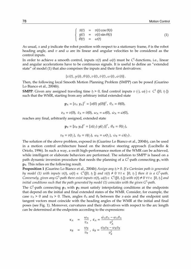
The solution of the above problem, exposed in (Guarino Lo Bianco et al., 2004b), can be used in a motion control architecture based on the iterative steering approach (Lucibello & Oriolo, 1996). In such a way, a swift high-performance motion of the WMR can be achieved, while intelligent or elaborate behaviors are performed. The solution to SMPP is based on a path dynamic inversion procedure that needs the planning of a G3-path connecting pA with pB. This relies on the following result. Proposition 1 (Guarino Lo Bianco et al., 2004b) Assign any tf > 0. If a Cartesian path is generated by model (1) with inputs v(t), ω(t) ∈ C1([0, tf ]) and v(t) ≠ 0 ∀t ∈ [0, tf ] then it is a G3-path. Conversely, given any G3-path there exist inputs v(t), ω(t) ∈ C1([0, tf ]) with v(t) ≠ 0 ∀t ∈ [0, tf ] and initial conditions such that the path generated by model (1) coincides with the given G3-path. The G3-path connecting pA with pB must satisfy interpolating conditions at the endpoints that depend on the initial and final extended states of the WMR. Consider, for example, the case vA > 0 and vB > 0. Then, angles θA and θB between the x-axis and the endpoint unit tangent vectors must coincide with the heading angles of the WMR at the initial and final poses (see Fig. 1). Moreover, curvatures and their derivatives with respect to the arc length can be determined at the endpoints according to the expressions:
Smooth Path Generation for Wheeled Mobile Robots Using η 3-Splines
79
Fig. 1. A G3-path connecting pA with pB for the SMPP. The critical cases vA = 0 and/or vB = 0, as well as other cases, are discussed in (Guarino Lo Bianco et al., 2004b). Proposition 1 makes clear that continuous curvature paths, or G2-paths, may be insufficiently smooth for a motion planning with fast and swift robot maneuvers. Indeed, with G2-paths the command accelerations can be discontinuous causing the possible slippage of the WMR. On the contrary, G3-paths are well suited for smooth motion planning because they can be followed with continuous accelerations commands.
4. The η3-splines In the context of smooth iterative steering for WMRs, the previous section has recalled the necessity of planning G3-paths having arbitrary interpolating conditions at the endpoints. Then, a natural approach is to find a polynomial curve for the associated interpolation problem. This justifies the introduction of the following formal problem. The polynomial G3-interpolating problem: Determine the minimal order polynomial curve which interpolates two given endpoints pA = [xA yA]T
and pB = [xB yB]T with associated unit tangent
vectors defined by angles θA and θB, scalar curvatures A and B, and curvature derivatives with respect to the arc length A and B (see Fig. 1). Assume that interpolating data pA, pB ∈ R2, θA, θB ∈ [0, 2π), A, B ∈ R and A, B ∈ R can be arbitrarily assigned. The solution proposed for the above interpolating problem is given by a seventh order polynomial curve p(u) = [α (u) β (u)]T, u ∈[0, 1] defined as follows
(2)
(3)
(4)
(5)
(6)
(7)

Motion Control
80
(8)
(9)
(10)
(11)
(12)
(13)
(14)
(15)
(16)
(17)
(18)
Smooth Path Generation for Wheeled Mobile Robots Using η 3-Splines
81
(19)
The real parameters ηi, i = 1,…, 6 which appear in (4)-(19), can be freely selected and influence the path shape without violating the endpoint interpolating conditions. They can be packed together to form a six-dimensional vector η := [η1 η2 η3 η4 η5 η6]T, and the parametric curve (2)-(3) will be concisely denoted in the following as p(u, η) or, informally, η3-spline. Vector η spans in denotes the set of positive real numbers). Coefficient expressions (4)-(19) were deduced by solving a nonlinear equation system associated to the endpoint interpolation conditions. The correctness of the provided expressions is formally stated by the following proposition. Proposition 2 The parametric curve p(u; η) satisfies any given set of interpolating data pA, θA, A,
A and pB, θB, B, B, for all η ∈ H. Proof – Basically, Proposition 2 asserts that curve p(u; η) fulfills any set of interpolating conditions independently from the choice of η. The proof can be then established by direct computation. Owing to definitions given for (s) and c(u), it is possible to write
or, briefly,
Bearing in mind this result and the definition of the unit tangent vector τ(u), curve p(u; η) satisfies the assigned boundary conditions if the following equalities hold for all η ∈ H.
(20)
(21)
(22)
(23)
(24)
(25)
(26)
(27)

Motion Control
82
First consider conditions (20) and (21). Taking into account that the parametric curve p(u; η) is described by means of (2) and (3), and its coefficients are defined according to (4)–(19), it is immediate to verify that, as required, p(0; η) = pA and p(1; η) = pB ∀η ∈ H. Further, differentiating p(u; η) with respect to u, we obtain where
(28)
(29)
Evaluating (u; η) for u = 0 and u = 1, and considering (4)–(19), it is easy to verify that, for all η ∈ H,
Bearing in mind that η1, η2 ∈R+, it follows that
(30)
(31)
and, consequently, as desired
According to the theory of planar curves, the scalar curvature can be evaluated by means of the formula
(32)
where can be obtained by differentiating (28) and (29), i.e.,
(33)
(34)
Applying (4)–(19) to (28)–(34) and evaluating c(u) for u = 0 and u = 1 we verify that, for all η ∈ H,
The first derivative of c(u) with respect to u is given by
(35)
An explicit differentiation of (33) and (34) makes it possible to write
Smooth Path Generation for Wheeled Mobile Robots Using η 3-Splines
83
(36)
(37)
The initial and final values of c can be then obtained from (35) by applying (4)–(19) to (28)–(37):
Both equalities hold for all η ∈ H. ■ The next result shows how the introduced η3-spline is a complete parameterization of all the seventh order polynomial curves interpolating given endpoint data. Property 1 (Completeness) Given any seventh order polynomial curve q(u), u ∈ [0; 1] with (0) ≠ 0 and (1) ≠ 0 which satisfies a given set of interpolating conditions pA, θA, A, A and pB, θB, B, B, there exists a parameter vector η ∈ H such that p(u; η) coincides with q(u). Proof – Consider a seventh order polynomial curve q(u) defined as follows
where
We assume that (0) ≠ 0, (1) ≠ 0, and all the interpolating conditions at the path endpoints are satisfied. Considering the zero and first order boundary conditions we have
which can be rewritten as follows
(38)
(39)

Motion Control
84
(40)
(41)
(42)
(43)
(44)
(45)
Further, taking into account that the scalar curvature c(u) of q(u) and its first derivative c(u) can be evaluated with expressions similar to (32) and (35), the second and third order
boundary conditions can be explicitly written as follows
(46)
(47)
(48)
(49)
The proof requires to show that there exists a parameter vector η ∈ H such that p(u; η) coincides with q(u), i.e., such that (i = 0, 1,…, 7)
To this aim, select the ηi parameters as follows
(50)
(51)
(52)
(53)

Smooth Path Generation for Wheeled Mobile Robots Using η 3-Splines
85
(54)
(55)
Owing to the above assignments, the interpolating conditions (38)–(49) on the polynomial curve q(u) can be rewritten as follows
(56)
(57)
(58)
(59)
(60)
(61)
(62)
(63)
(64)
(65)
(66)
(67)
From definitions (4) and (12) and relations (56) and (57) obviously we get
Analogously, from (5) and (13), and taking into account (60) and (61), it is possible to infer
Owing to definition (52) and condition (64), we obtain from (6) and (14)
Motion Control
86
In the same way, from (7) and (15), and taking into account (54) and (66), it is possible to verify
Focusing on the αi expressions given by (8)–(11), the ηi definitions (52)–(55), and the interpolating equations (56), (58), (60), (62), (64)–(67) we obtain, after some algebraic manipulations, to express α4, α5, α6, and α7 as a linear combinations of
Then, by virtue of the definition given for γ(u), it is easy to verify that αi = γi for i = 4, 5, 6, 7. A similar procedure can be also adopted for the remaining βi coefficients by manipulating (52)–(55), (57), (59), (61), (63), (64)–(67) and replacing the resulting expressions in (16)–(19). These final passages are left to the interested reader. The minimality of the η3-spline is the focus of the next statement. ■ Property 2 (Minimality) The curve p(u; η) is the minimal order polynomial curve interpolating any arbitrarily given set of data pA, pB ∈ R2, θA, θB ∈ [0, 2π), A, B∈ R and A, B ∈ R. Proof – Proposition 2 and Property 1 have shown that the η3-spline p(u; η) is the family of all polynomial curves, till to the seventh order, interpolating any given endpoint data. Hence, if a sixth or lower order polynomial curve exists interpolating any assigned set of boundary conditions, it must coincide with p(u; η) for some appropriate η ∈ H. Consider the following boundary conditions (leading to a so-called lane-change path):
and evaluate the η3-spline curve using (4)–( 19)

Smooth Path Generation for Wheeled Mobile Robots Using η 3-Splines
87
Evidently, β(u; η) is a strict seventh order polynomial that does not depend on η. Thus, it is not possible to interpolate the given data with a sixth or lower order polynomial curve. ■ Proposition 2 and Property 2 show that the η3-spline is the solution to the introduced G3-interpolating problem. Moreover, the η3-spline represents a family of curves that depends on a symmetric parameterization induced by the chosen η vector. This property, presented below formally, may be useful in shaping the η3-spline by varying the ηi components. Property 3 (Symmetry) Assume η1 = η2 = v ∈ R+, η3 = –η4 = w ∈ R, η5 = η6 = z ∈ R and define η = [v v w – w z z]T. Moreover, consider θA = θB = θ ∈ [0, 2π), A = B = 0, A = B = 0. Then, for any pA and pB, curve p(u; η) satisfies the following symmetry relation
(68)
∀u ∈ [0, 1], ∀v ∈ R+, ∀w, z ∈ R.
Fig. 2. A graphical interpretation of symmetry relation (68).
Proof – It is always possible to find d1, d2 ∈ R such that (cf. Fig. 2)
Curve p(u; η), evaluated by means of (4)–(19) and the assigned interpolating conditions, can be expressed as
Motion Control
88
(69)
Now, use (69) to evaluate p(u; η) + p(1 – u; η). Some algebraic manipulations are required to obtain
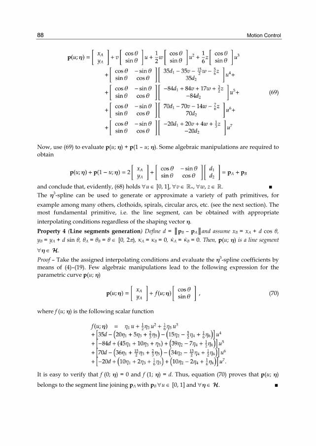
and conclude that, evidently, (68) holds ∀u ∈ [0, 1], ∀v ∈ R+, ∀w, z ∈ R. ■ The η3-spline can be used to generate or approximate a variety of path primitives, for example among many others, clothoids, spirals, circular arcs, etc. (see the next section). The most fundamental primitive, i.e. the line segment, can be obtained with appropriate interpolating conditions regardless of the shaping vector η. Property 4 (Line segments generation) Define d = ║pB – pA║and assume xB = xA + d cos θ, yB = yA + d sin θ, θA = θB = θ ∈ [0, 2π), A = B = 0, A = B = 0. Then, p(u; η) is a line segment
∀η ∈ H. Proof – Take the assigned interpolating conditions and evaluate the η3-spline coefficients by means of (4)–(19). Few algebraic manipulations lead to the following expression for the parametric curve p(u; η)
(70)
where f (u; η) is the following scalar function
It is easy to verify that f (0; η) = 0 and f (1; η) = d. Thus, equation (70) proves that p(u; η)
belongs to the segment line joining pA with pB ∀u ∈ [0, 1] and ∀η ∈ H. ■
Smooth Path Generation for Wheeled Mobile Robots Using η 3-Splines
89
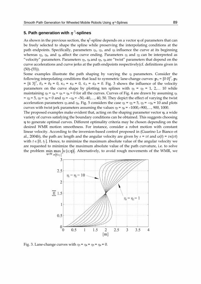
5. Path generation with η 3-splines
As shown in the previous section, the η3-spline depends on a vector η of parameters that can be freely selected to shape the spline while preserving the interpolating conditions at the path endpoints. Specifically, parameters η1, η3, and η5 influence the curve at its beginning whereas η2, η4, and η6 affect the curve ending. Parameters η1 and η2 can be interpreted as “velocity” parameters. Parameters η3, η4 and η5, η6 are “twist” parameters that depend on the curve accelerations and curve jerks at the path endpoints respectively(cf. definitions given in (50)-(55)). Some examples illustrate the path shaping by varying the ηi parameters. Consider the following interpolating conditions that lead to symmetric lane-change curves: pA = [0 0]T, pB
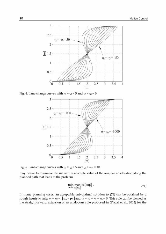
= [4 3]T, θA = θB = 0, A = B = 0, A = B = 0. Fig. 3 shows the influence of the velocity parameters on the curve shape by plotting ten splines with η1 = η2 = 1, 2,… 10 while maintaining η3 = η4 = η5 = η6 = 0 for all the curves. Curves of Fig. 4 are drawn by assuming η1
= η2 = 5, η5 = η6 = 0 and η3 = –η4 = –50,–40,…, 40, 50. They depict the effect of varying the twist acceleration parameters η3 and η4. Fig. 5 considers the case η1 = η2 = 5, η3 = –η4 = 10 and plots curves with twist jerk parameters assuming the values η5 = η6 = –1000,–900,…, 900, 1000. The proposed examples make evident that, acting on the shaping parameter vector η, a wide variety of curves satisfying the boundary conditions can be obtained. This suggests choosing η to generate optimal curves. Different optimality criteria may be chosen depending on the desired WMR motion smoothness. For instance, consider a robot motion with constant linear velocity. According to the inversion-based control proposed in (Guarino Lo Bianco et al., 2004b), the path arc length and the angular velocity are given by s = vt and ω(t) = vκ(vt) with t ∈[0, tf ]. Hence, to minimize the maximum absolute value of the angular velocity we are requested to minimize the maximum absolute value of the path curvature, i.e. to solve the problem
Alternatively, to avoid rough movements of the WMR, we
Fig. 3. Lane-change curves with η3 = η4 = η5 = η6 = 0.
Motion Control
90
Fig. 4. Lane-change curves with η1 = η2 = 5 and η5 = η6 = 0.
Fig. 5. Lane-change curves with η1 = η2 = 5 and η3 = –η4 = 10.
may desire to minimize the maximum absolute value of the angular acceleration along the planned path that leads to the problem
(71)
In many planning cases, an acceptable sub-optimal solution to (71) can be obtained by a rough heuristic rule: η1 = η2 = ║pA – pB║and η3 = η4 = η5 = η6 = 0. This rule can be viewed as the straightforward extension of an analogous rule proposed in (Piazzi et al., 2002) for the
Smooth Path Generation for Wheeled Mobile Robots Using η 3-Splines
91
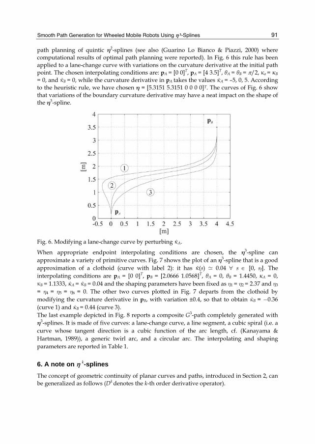
path planning of quintic η2-splines (see also (Guarino Lo Bianco & Piazzi, 2000) where computational results of optimal path planning were reported). In Fig. 6 this rule has been applied to a lane-change curve with variations on the curvature derivative at the initial path point. The chosen interpolating conditions are: pA = [0 0]T, pA = [4 3.5]T, θA = θB = π/2, a = B
= 0, and B = 0, while the curvature derivative in pA takes the values A = –5, 0, 5. According to the heuristic rule, we have chosen η = [5.3151 5.3151 0 0 0 0]T. The curves of Fig. 6 show that variations of the boundary curvature derivative may have a neat impact on the shape of the η3-spline.
Fig. 6. Modifying a lane-change curve by perturbing A.
When appropriate endpoint interpolating conditions are chosen, the η3-spline can approximate a variety of primitive curves. Fig. 7 shows the plot of an η3-spline that is a good approximation of a clothoid (curve with label 2): it has (s) 0.04 ∀ s ∈ [0, sf]. The interpolating conditions are pA = [0 0]T, pB = [2.0666 1.0568]T, θA = 0, θB = 1.4450, A = 0,
B = 1.1333, A = B = 0.04 and the shaping parameters have been fixed as η1 = η2 = 2.37 and η3
= η4 = η5 = η6 = 0. The other two curves plotted in Fig. 7 departs from the clothoid by modifying the curvature derivative in pB, with variation ±0.4, so that to obtain B = −0.36 (curve 1) and B = 0.44 (curve 3). The last example depicted in Fig. 8 reports a composite G3-path completely generated with η3-splines. It is made of five curves: a lane-change curve, a line segment, a cubic spiral (i.e. a curve whose tangent direction is a cubic function of the arc length, cf. (Kanayama & Hartman, 1989)), a generic twirl arc, and a circular arc. The interpolating and shaping parameters are reported in Table 1.
6. A note on η k-splines The concept of geometric continuity of planar curves and paths, introduced in Section 2, can be generalized as follows (Dk denotes the k-th order derivative operator).

Motion Control
92
Fig. 7. Modifying a clothoid by perturbing B.
Fig. 8. A composite G3-path made by η3-splines.
Table 1. The interpolating parameters and the ηi coefficients used to generate the composite G3-path of Fig. 8.

Smooth Path Generation for Wheeled Mobile Robots Using η 3-Splines
93
Definition 3 (Gk-curves; k ≥ 2) A parametric curve p(u) has k-th order geometric continuity and we say p(u) is a Gk-curve if p(u) is Gk–1-curve, Dkp(·) ∈ Cp([u0, u1]), and Dk–2κ (·) ∈ C0([0, sf
]). Definition 4 (Gk-paths; k ≥2) A set of points of a Cartesian plane is a Gk-path if there exists a parametric Gk-curve whose image is the given path. Roughly speaking, the k-th order geometric continuity of curves amounts to the continuity of the curvature function up to the (k – 2)-nd derivative. In a more general setting, geometric continuity is treated in (Peters, 2002). Now we can naturally state the polynomial Gk-interpolating problem as the generalization of the G3-problem of Section 4. The polynomial Gk-interpolating problem: Determine the minimal order polynomial curve which interpolates two given endpoints pA = [xA yA]T
and pB = [xB yB]T with associated unit tangent
vectors defined by angles θA and θB, and curvature derivatives DiκA and DiκB for i = 0, 1,…, k – 2. All the endpoint interpolating data can be arbitrarily assigned. Then, following the approach proposed in Section 4, we could derive the ηk-spline as the solution of the above problem characterized by minimality, completeness, and symmetry. For k = 2 this has been done in (Piazzi & Guarino Lo Bianco, 2000) and the deduced η2 splines are quintic polynomial curves that depend on a four-dimensional η vector (η ∈ × R2 is the vector of the shaping parameters). The η2-splines have been proposed for autonomous guidance of cars (Piazzi et al., 2002) and of wheeled omnidirectional robots (Guarino Lo Bianco et al., 2004a). The remaining elementary cases k = 1 and k = 0 leading to the η1-spline and the η0-spline are reported in the Appendix. On the grounds of the already found ηk-splines (k = 0, 1, 2, 3) we infer that the general ηk -spline is a polynomial curve with order equal to 2k + 1 and whose parameterization depends on a shaping vector η with 2k components (η ∈ 2
+R × R2(k–1)). Closed-form expressions of the ηk-spline could be generated by suitably devised computer algebra procedures. Formally define ηk-Paths as the set of all the paths given by the ηk-splines for all η ∈ 2
+R × R2(k–1) and all the endpoint interpolation data. Then, the following property holds. Property 5 ηk -Paths ⊂ ηk +1-Paths for all k ∈ N.
This property helps to explain why the η3-splines are quite good in approximating standard curve primitives. Indeed, it was already shown in (Guarino Lo Bianco & Piazzi, 2000) that η2-splines can very well approximate circular arcs or clothoids so that η3-splines can only better the approximations with further curve inclusions such as, for example, cubic spirals (see previous Section 5). Following (Guarino Lo Bianco et al., 2004b) we can foresee the use of η4-splines to achieve for WMRs the generation of velocity commands with continuous jerk signals (signals with continuous acceleration derivatives).
7. Conclusions This chapter has presented the η3-spline, a seventh order polynomial curve that interpolates between two Cartesian points with arbitrary assigned tangent vectors, curvatures and curvature derivatives. This curve primitive, given with explicit closed-form expressions, depends on a shaping parameter vector that can be freely chosen to shape or optimize the path. An advantage of the new spline over other curve primitives, such as clothoids or polynomial spirals, is the avoidance of any numerical integration/procedure to evaluate the curve coordinates. Properties of the η3-spline such as completeness, minimality, and

Motion Control
94
symmetry have been also reported. Investigations on optimal η3-splines have been reported in (Guarino Lo Bianco & Gerelli, 2007; Gerelli, 2009). How to achieve high-performance motion control of WMRs with the η3-spline in conjunction with obstacle avoidance capabilities has been addressed in (Villagra & Mounier, 2005; Chang & Liu, 2009).
8. Appendix Case k = 1 (solution to the polynomial G1-interpolating problem). The η1-spline is a third-order polynomial curve p(u; η) u ∈ [0, 1], η = [η1η2]T ∈ with coefficients defined as follows.
Case k = 0 (solution to the polynomial G0-interpolating problem). For completeness we also give the η0-spline which is simply expressed by the first-order curve p(u) = pA + pB · u, u ∈ [0, 1]. There are no shaping parameters as the curve is just the line segment connecting pA
with pB. Note that zero-order geometric continuity coincides with the standard notion of function continuity (C0-continuity).
9. References Barsky, B. A. & Beatty, J. C. (1983). Local control of bias and tension in beta-spline. Computer
Graphics, Vol. 17, No. 3, pp. 193–218. Boissonnat, J.-D., Cérézo, A. & Leblond, J. (1994). A note on shortest paths in the plane
subject to a constraint on the derivative of the curvature. Tech. Rep. 2160, INRIA, Rocquencourt, France.
Chang, H.-C. & Liu, J.-S. (2009). High-quality path planning for autonomous mobile robots with η3-splines and parallel genetic algorithms. Robotics and Biomimetics, 2008. ROBIO 2008. IEEE International Conference on, pp. 1671–1677. doi: 10.1109/ROBIO.2009.4913252.
Choset, H., Lynch, K., Hutchinson, S., Kantor, G., Burgard, W., Kavraki, L. & Thrun, S. (2005). Principles of Robot Motion: Theory, Algorithms, and Implementations. The MIT Press, Cambridge, MA.
Delingette, H., Hébert, M.&Ikeuchi, K. (1991). Trajectory generation with curvature constraint based on energy minimization. Proc. of the IEEE-RSJ Int. Conf. on Intelligent Robots and Systems, pp. 206–211. Osaka, Japan.
Fraichard, T. & Scheuer, A. (2004). From Reeds and Shepp’s to continuous-curvature paths. IEEE Trans. on Robotics, Vol. 20, No. 6, pp. 1025–1035.

Smooth Path Generation for Wheeled Mobile Robots Using η 3-Splines
95
Gerelli, O. (2009). Optimal Constrained Planning for Complex Mechatronic Systems. Phd thesis, Universitá di Parma, Dipartimento di Ingegneria dell’Informazione, Parma, Italy.
Guarino Lo Bianco, C. & Gerelli, O. (2007). Optimal path generation for wheeled mobile robots with η3-splines. Proceedings of the 13th IEEE IFAC Int. Conf. on Methods and Models in Automation and Robotics, pp. 1049–1054. Szczecin, Poland.
Guarino Lo Bianco, C.&Piazzi, A. (2000). Optimal trajectory planning with quintic G2-splines. Procs of the IEEE Intelligent Vehicles Symposium, IV2000, pp. 620–625. Dearborn (MI), USA.
Guarino Lo Bianco, C., Piazzi, A. & Romano, M. (2004a). Smooth control of a wheeled omnidirectional robot. Proc. of the IFAC Symp. on Intelligent Autonomous Vehicles, IAV2004. Lisbon, Portugal.
——— (2004b). Smooth motion generation for unicycle mobile robots via dynamic path inversion. IEEE Trans. on Robotics, Vol. 20, No. 5, pp. 884–891.
Hsiung, C.-C. (1997). A First Course in Differential Geometry. International Press, Cambrige,MA.
Kanayama, Y. & Hartman, B. (1989). Smooth local path planning for autonomous vehicles. Proc. of the IEEE Int. Conf. on Robotics and Automation, Vol. 3, pp. 1265–1270. Scottsdale, AZ (US).
Kant, K. & Zucker, S. (1986). Toward efficient trajectory planning: the path-velocity decomposition. Int. J. of Robotics Research, Vol. 5, No. 3, pp. 72–89.
Kito, T., Ota, J., Katsuki, R., Mizuta, T., Arai, T., Ueyama, T. & Nishiyama, T. (2003). Smooth path planning by using visibility graph-like method. Proc. of the IEEE Inter. Conf. on Robotics & Automation, pp. 3770–3775. Taipei, Taiwan.
Labakhua, L., Nunes, U., Rodrigues, R. & Leite, F. (2006). Smooth trajectory planning for fully automated passengers vehicles: Spline and clothoid based methods and its simulation. J. P. J. Andrade-Cetto, J.-L. Ferrier&J. Filipe, (Eds.) Informatics in Control Automation and Robotics. Springer, Berlin.
Lucibello, P. & Oriolo, G. (1996). Stabilization via iterative state steering with application to chained-form systems. Proc. of the 35th IEEE Conf. on Decision and Control, Vol. 3, pp. 2614–2619. Kobe, Japan.
Morin, P. & Samson, C. (2008). Motion control of wheleed mobile robots. B. Sicilano & O. Khatib, (Eds.) Springer Handbook of Robotics, pp. 799–826. Springer, Berlin.
Nelson, W. (1989). Continuous steering-function control of robot carts. IEEE Trans. on Ind. Electronics, Vol. 36, No. 3, pp. 330–337.
Peters, J. (2002). Geometric continuity. G. Farin, J. Hoschek & M.-S. Kim, (Eds.) Handbook of Computer Aided Geometric Design, pp. 193–229. North-Holland.
Piazzi, A. & Guarino Lo Bianco, C. (2000). Quintic G2-splines for trajectory planning of autonomous vehicles. Procs of the IEEE Intelligent Vehicles Symposium, pp. 198–203. Dearborn (MI), USA.
Piazzi, A., Guarino Lo Bianco, C., Bertozzi, M., Fascioli, A. & Broggi, A. (2002). Quintic G2-splines for the iterative steering of vision-based autonomous vehicles. IEEE Trans. On Intelligent Transportations Systems, Vol. 3, No. 1, pp. 27–36.
Piazzi, A., Guarino Lo Bianco, C. & Romano, M. (2007). η3-splines for the smooth path generation of wheeled mobile robots. Robotics, IEEE Transactions on, Vol. 23, No. 5, pp. 1089–1095. ISSN 1552-3098. doi:10.1109/TRO.2007.903816.

Motion Control
96
Reuter, J. (1998). Mobile robots trajectories with continuously differentiable curvature: an optimal control approach. Proc. of the 1998 IEEE/RSJ Int. Conf. on Intelligent Robots and Systems, Vol. 1, pp. 38–43. Victoria, B.C., Canada.
Scheuer, A. & Laugier, C. (1998). Planning sub-optimal and continuous-curvature paths for car-like robots. Proceedings of the 1998 IEEE/RSJ International Conference on Intelligent Robots and Systems, pp. 25–31. Victoria, B.C., Canada.
Suzuki, Y., Thompson, S.&Kagami, S. (2009). Smooth path planning with pedestrian avoidance for wheeled robots: Implementation and evaluation. Autonomous Robots and Agents, 2009. ICARA 2009. 4th International Conference on, pp. 657–662. doi:10.1109/ICARA.2000.4803910.
Villagra, J. & Mounier, H. (2005). Obstacle-avoiding path planning for high velocity wheeled mobile robots. Proceedings of the IFAC World Congress. Prague, Czech Republic.