Embed Size (px)
Citation preview
Technical PaperIssue/Rev. 0.1 (5/09) Bulletin TP02006
Smith Meter® Turbine Meters
Utilizing the Smith Meter ® UPC Compensator with Helical
Rotor Turbine Meters
The Most Trusted Name In Measurement
Purpose of UPCC
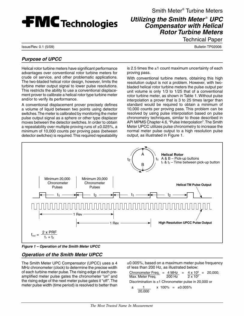
is 2.5 times the ±1 count maximum uncertainty of each proving pass. With conventional turbine meters, obtaining this high resolution output is not a problem. However, with two-bladed helical rotor turbine meters the pulse output per unit volume is only 1/3 to 1/25 that of a conventional rotor turbine meter, as shown in Table 1. Without pulse interpolation a prover that is 3 to 25 times larger than standard would be required to obtain a minimum of 10,000 counts per proving pass. This problem can be resolved by using pulse interpolation based on pulse chronometry techniques, similar to those described in API MPMS Chapter 4.6, “Pulse Interpolation”. The Smith Meter UPCC utilizes pulse chronometry to increase the normal meter pulse output to a high resolution pulse output, as illustrated in Figure 1.
t1
Minimum 20,000Chronometer
Pulses
Minimum 20,000Chronometer
Pulses
1 Rev
1 Rev
t2 t1 t2
A
Bt1t2
Helical TM Pulse Output
High Resolution UPCC Pulse Output
Helical RotorA & B – Pick-up buttonst1 & t2 – Time between pick-up button
fout = 2 x PRF
t1 + t2
Figure 1 – Operation of the Smith Meter UPCC
Operation of the Smith Meter UPCC
The Smith Meter UPC Compensator (UPCC) uses a 4 MHz chronometer (clock) to determine the precise width of each turbine meter pulse. The rising edge of each pre-amplified meter pulse gates the chronometer “on” and the rising edge of the next meter pulse gates it “off”. The meter pulse width (time period) is resolved to better than
Helical rotor turbine meters have significant performance advantages over conventional rotor turbine meters for crude oil service, and other problematic applications. The two-bladed helical rotor design, however, limits the turbine meter output signal to lower pulse resolutions. This restricts the ability to use a conventional displace-ment prover to calibrate a helical rotor type turbine meter and/or to verify its performance.A conventional displacement prover precisely defines a volume of liquid between two points using detector switches. The meter is calibrated by monitoring the meter pulse output signal as a sphere or other type displacer moves between the detector switches. In order to obtain a repeatability over multiple proving runs of ±0.025%, a minimum of 10,000 counts per proving pass (between detector switches) is required. This required repeatability
±0.005%, based on a maximum meter pulse frequency of less than 200 Hz, as illustrated below:
Chronometer Freq. = 4 MHz = 4 x 106 = 20,000;Max. Meter Freq. 200 Hz 2 x 10²
Discrimination is ±1 Chronometer pulse in 20,000 or
± 1 x 100% = ±0.005% 20,000

Issue/Rev. 0.1 (5/09)Page 2 • TP02006
Pulse Resolution Factor (PRF) Table 1 Conventional Turbine Meter MV Turbine Meter MVTM with PRF Meter Max Flow K Factor Meter Output K-Factor Meter Output Suggested K-Factor Meter Output Size BPH Freq. (Hz)1 Freq. (Hz)1 (PRF) Freq. (Hz)1
3" 900 2,215 665 600 180 10 6,000 1,800
4" 1,900 2,100 1,330 250 158 10 2,500 1,583
6" 4,000 1,050 1,400 100 133 12 1,200 1,600
8" 7,500 525 1,313 40 100 15 600 1,500
10" 12,500 525 2,188 19 77 20 380 1,583
12" 19,000 265 1,678 11 70 25 275 1,742
16" 27,000 105 945 6 54 35 210 1,890
The width of the next pulse is assumed to be equal to the average width of the two previous pulses (i.e., the time of the last complete rotor rev, divided by two). With this assumption the UPCC accurately divides the subsequent pulse to the programmed pulse resolution.
Comparison of UPCC Method to Dual-Chronometry Pulse Interpolation (DCPI) Method for Proving Helical Rotor Turbine Meters
UPCC MethodWith the UPCC method, the total width of each of the two interpolated pulses is assumed to be equal to the average width of the previous two meter pulses. The following factors affect the validity of this assumption:
• Meter pulse continuity (i.e., dimensional width be-tween rotor blades) variation (Maximum variation: ±5% of average, per API MPMS 4.6.2.2.b).
• Flow rate variation over 1.5 rotor revs (Nil).The maximum RSS uncertainty in the width of both interpolated pulses is about ±7% from these potential error sources. With a proving pass of 400 meter puls-es, the maximum proving pass uncertainty from these potential error sources is on the order of ±0.0175% (i.e., 7% maximum uncertainty 400 meter pulses
= 0.0175%).
To this potential error must be added the ±1 count (i.e., ±0.01% for 10,000 counts) maximum prover pulse gating uncertainty. Taking the RSS of these two potential errors yields a maximum proving pass uncertainty using the UPCC method of about ±0.020%; somewhat less than the ±0.025% proving pass uncertainty using the DCPI method described above.
The Pulse Resolution Factor (PRF) can be any whole number between 1 and 50. Table 1 lists the suggested PRF’s for Smith MV Series turbine meters. Note that the maximum output frequency of the UPCC must not exceed 2000 Hz.
1 Includes a 20% turbine meter overspeed.2 API MPMS Chapter 4.6 “Pulse Interpolation” acknowledges that there are various techniques for pulse interpolation. For example: From 4.6.1 Introduction: “The pulse-interpolation method known as double-chronometry, described in this chapter, is an established technique
used in proving flowmeters. As other methods of pulse interpolation become accepted industry practice, they should receive equal consider-ation, provided that they can meet the established verification tests and specifications described in this publication.”
From 4.6.1.7.11: “Pulse-interpolation is defined as any of the various techniques by which the whole number of meter pulses is counted be-tween two events (such as detector switch closures); any remaining fraction of a pulse between the two events is calculated.”
Reference API Coordinating Committee Meeting Minutes 10/5/99, Denver, CO.
The API COLM Coordinating Committee reviewed Bulletin TP02006. The group concluded that the UPCC is in accordance with MPMS and that any user concerns about its operation should be addressed by FMC Technologies Measurement Solutions, Inc.
Proving a low frequency output helical rotor turbine meter using a Smith Meter UPCC is similar to proving it with Dual-Chronometry Pulse Interpolation (DCPI), as described in API MPMS Chapter 4.62. Both methods in-terpolate the width of the fractions of a meter pulse at the beginning and end of a proving pass using high speed chronometry. However, the potential proving uncertainty using the Smith Meter UPCC method is less than with the DCPI method, for the reasons described below.DCPI MethodWith the DCPI method the total width of each of the two interpolated pulses is assumed to be equal to the average width of all of the meter pulses during the prov-ing pass. The following factors affect the validity of this assumption, and thus the uncertainty of each proving pass using this method:
• Meter pulse continuity (i.e., dimensional width be-tween rotor blades) variation (Maximum variation: ±5% of average , per API MPMS 4.6.2.2.b).
• Flow rate variation over the entire proving pass (Maximum variation: ±5% of average assumed).
Taking the Root Sum of the Squares (RSS) of these two effects on pulse width yields a possible maximum uncertainty of about ±7% in the width of each of the two interpolated pulses, or about ±10% maximum RSS uncertainty for both interpolated pulses. With a proving pass of 400 meter pulses (typical for a 10” he-lical rotor turbine meter using a displacement prover sized for a conventional 10” turbine meter), the maxi-mum proving pass uncertainty using the DCPI method is on the order of ±0.025% (i.e., 10% maximum uncertainty 400 meter pulses
= 0.025%).


Visit our website at www.fmctechnologies.com/measurementsolutionsPrinted in U.S.A. © 5/09 FMC Technologies Measurement Solutions, Inc. All rights reserved. TP02006 Issue/Rev. 0.1 (5/09)
The specifications contained herein are subject to change without notice and any user of said specifications should verify from the manufacturer that the specifications are currently in effect. Otherwise, the manufacturer assumes no responsibility for the use of specifications which may have been changed and are no longer in effect.
Headquarters:500 North Sam Houston Parkway West, Suite 100, Houston, TX 77067 USA, Phone: +1 (281) 260-2190, Fax: +1 (281) 260-2191
Gas Measurement Products: Houston, TX USA +1 (281) 260-2190Thetford, England +44 (1842) 82-2900Kongsberg, Norway +47 (32) 286-700Buenos Aires, Argentina +54 (11) 4312-4736
Integrated Measurement Systems:Corpus Christi, TX USA +1 (361) 289-3400Kongsberg, Norway +47 (32) 286-700San Juan, Puerto Rico +1809 (787) 274-3760United Arab Emirates, Dubai +971 (4) 331-3646
Liquid Measurement Products:Erie, PA USA +1 (814) 898-5000Los Angeles, CA USA +1 (310) 328-1236 Slough, England +44 (1753) 57-1515Ellerbek, Germany +49 (4101) 304-0Barcelona, Spain +34 (93) 201-0989Moscow, Russia +7 (495) 564-8705Melbourne, Australia +61 (3) 9807-2818
Beijing, China +86 (10) 6500-2251Singapore +65 6861-3011Chennai, India +91 (44) 450-4400
Revisions included in TP02006 Issue/Rev. 0.1 (5/09): Page 2: Corrections made to Pulse Resolution Factor table.