Embed Size (px)
Citation preview
SMART - SAFE - INNOVATIVE2N ELEVATOR SYSTEMS - Emergency communication devices for any lift.

“For 28 years 2N has been on the forefront of access control and telecommunications. We take care to stay on the leading edge with our products, the R&D behind them, and the way we service our customers. We are proud of our growth on global markets and growing number of key players in elevator market becoming our customers.”
ABOUT THE COMPANY
PETER LINDSTRÖMVice President New Business, Axis Communications
„AXIS Group including 2N have a common goal to contribute to a smarter and safer world. There is an increased customer demand for integrated solutions with open standards that deliver enhanced security. Together with 2N we can meet that demand.“
MICHAL KRATOCHVÍLCEO, 2N Telekomunikace a.s.
2N® LIFT1
2N® LIFTIP
2N® LIFT8
2N LIFT SOFTWARE
3
5
9
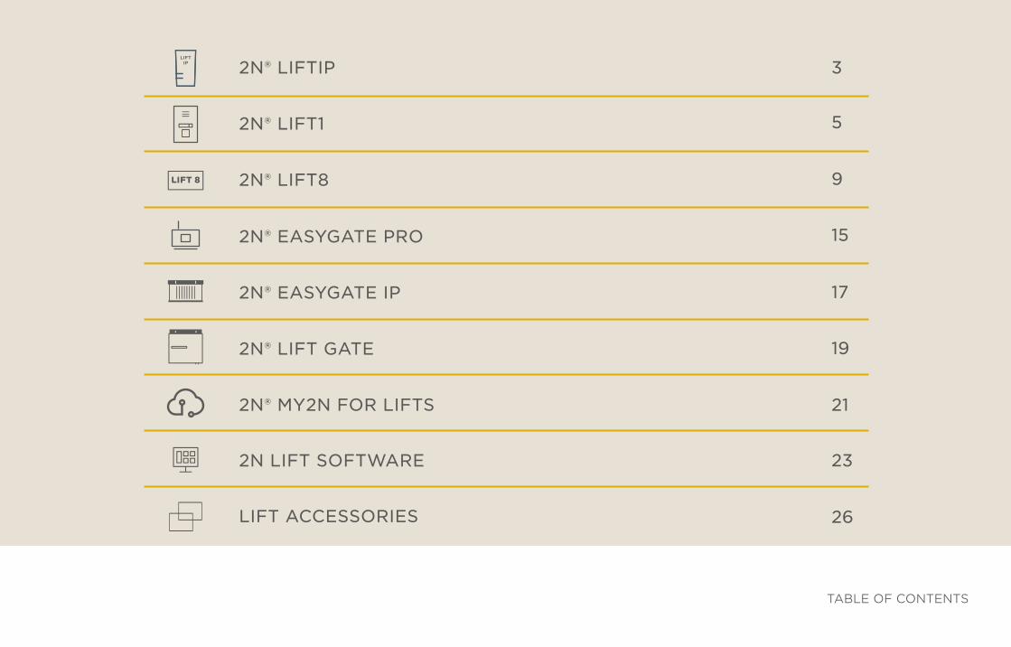
TABLE OF CONTENTS
LIFT IP
LIFT 8
LIFT ACCESSORIES 26
21
2N® EASYGATE PRO 15
23
19
2N® EASYGATE IP
2N® LIFT GATE
2N® MY2N FOR LIFTS
17
3
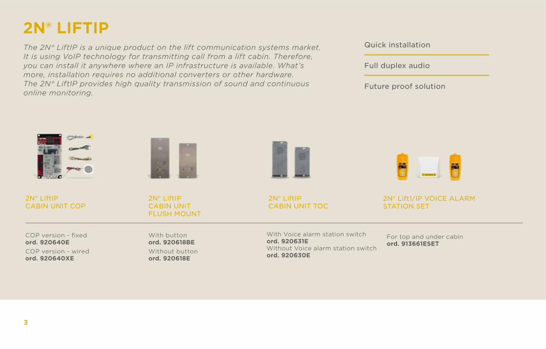
Quick installation
Full duplex audio
Future proof solution
2N® LiftIP CABIN UNIT COP
2N® LIFTIPThe 2N® LiftIP is a unique product on the lift communication systems market. It is using VoIP technology for transmitting call from a lift cabin. Therefore, you can install it anywhere where an IP infrastructure is available. What’s more, installation requires no additional converters or other hardware. The 2N® LiftIP provides high quality transmission of sound and continuous online monitoring.
COP version - fixedord. 920640ECOP version - wiredord. 920640XE
2N® LiftIP CABIN UNIT FLUSH MOUNT
With buttonord. 920618BEWithout buttonord. 920618E
2N® LiftIP CABIN UNIT TOC
With Voice alarm station switchord. 920631EWithout Voice alarm station switchord. 920630E
2N® Lift1/IP VOICE ALARMSTATION SET
For top and under cabin ord. 913661ESET
4
LAN/WAN
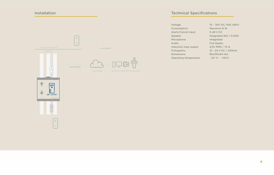
LIFTIP
LIFTIP
CABIN
SHAFT
MACHINE ROOM
DISPATCHER/SUPERVISOR
2N® LIFTIP
LAN/ETHERNET
LAN/ETHERNET
Installation Technical Specifications
Voltage 10 – 30V DC, PoE (48V)Consumption Maximum 6 WAlarm/Cancel input 5-48 V DC
Speaker Integrated 16Ω / 0.25WMicrophone IntegratedAudio Full duplexInduction loop output 0,5V RMS / 75 ΩPictograms 12 – 24 V DC / 200mADimensions 65x130x24 mmOperating temperature - 20 oC - +50oC
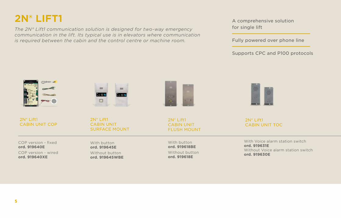
2N® LIFT1The 2N® Lift1 communication solution is designed for two-way emergency communication in the lift. Its typical use is in elevators where communication is required between the cabin and the control centre or machine room.
A comprehensive solution for single lift
Fully powered over phone line
Supports CPC and P100 protocols
2N® Lift1 CABIN UNIT COP
COP version - fixedord. 919640ECOP version - wiredord. 919640XE
2N® Lift1 CABIN UNIT SURFACE MOUNT
With buttonord. 919645EWithout buttonord. 919645WBE
2N® Lift1 CABIN UNIT FLUSH MOUNT
With buttonord. 919618BEWithout buttonord. 919618E
2N® Lift1 CABIN UNIT TOC
With Voice alarm station switchord. 919631EWithout Voice alarm station switchord. 919630E
5
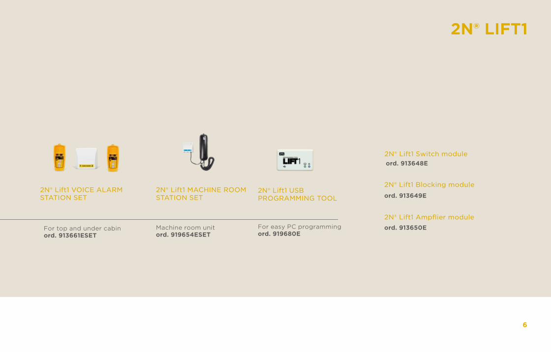
2N® Lift1 VOICE ALARMSTATION SET
For top and under cabin ord. 913661ESET
2N® Lift1 MACHINE ROOM STATION SET
Machine room unitord. 919654ESET
2N® Lift1 USBPROGRAMMING TOOL
For easy PC programmingord. 919680E
2N® Lift1 Switch moduleord. 913648E
2N® LIFT1
2N® Lift1 Blocking module
2N® Lift1 Ampflier module
ord. 913649E
ord. 913650E
6
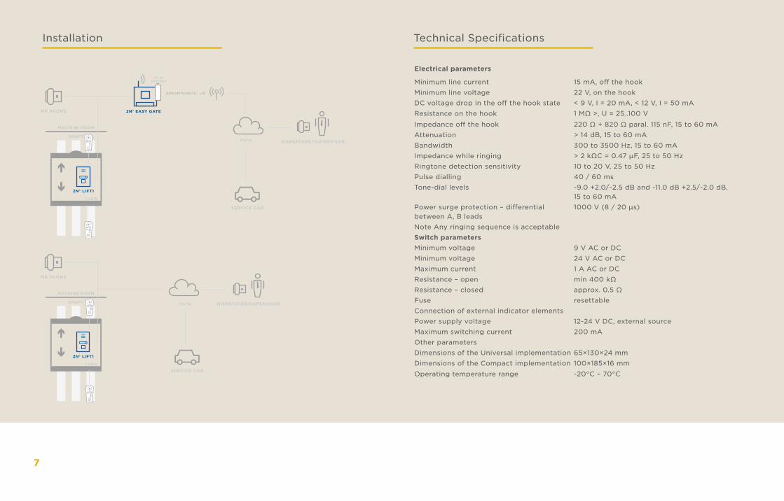
Installation Technical Specifications
Electrical parameters
Minimum line current 15 mA, off the hookMinimum line voltage 22 V, on the hookDC voltage drop in the off the hook state < 9 V, I = 20 mA, < 12 V, I = 50 mAResistance on the hook 1 MΩ >, U = 25..100 V
Impedance off the hook 220 Ω + 820 Ω paral. 115 nF, 15 to 60 mAAttenuation > 14 dB, 15 to 60 mABandwidth 300 to 3500 Hz, 15 to 60 mAImpedance while ringing > 2 kΩC = 0.47 µF, 25 to 50 HzRingtone detection sensitivity 10 to 20 V, 25 to 50 HzPulse dialling 40 / 60 msTone-dial levels -9.0 +2.0/-2.5 dB and -11.0 dB +2.5/-2.0 dB,
15 to 60 mAPower surge protection – differential between A, B leads
1000 V (8 / 20 µs)
Note Any ringing sequence is acceptableSwitch parametersMinimum voltage 9 V AC or DCMinimum voltage 24 V AC or DCMaximum current 1 A AC or DCResistance – open min 400 kΩResistance – closed approx. 0.5 ΩFuse resettableConnection of external indicator elementsPower supply voltage 12-24 V DC, external sourceMaximum switching current 200 mAOther parametersDimensions of the Universal implementation 65×130×24 mmDimensions of the Compact implementation 100×185×16 mm
Operating temperature range -20°C – 70°C
CABIN
SHAFT
MACHINE ROOM
PSTN DISPATCHER/SUPERVISOR
SERVICE CAR
2N® LIFT1
MR PHONE
2N® EASY GATE
CABIN
SHAFT
MACHINE ROOM
PSTN DISPATCHER/SUPERVISOR
SERVICE CAR
2N® LIFT1
MR PHONE
4X AABATTERY
GSM/UMTS/VoLTE / LTE
7
Electrical parameters
Minimum line current 15 mA, off the hookMinimum line voltage 22 V, on the hookDC voltage drop in the off the hook state < 9 V, I = 20 mA, < 12 V, I = 50 mAResistance on the hook 1 MΩ >, U = 25..100 V
Impedance off the hook 220 Ω + 820 Ω paral. 115 nF, 15 to 60 mAAttenuation > 14 dB, 15 to 60 mABandwidth 300 to 3500 Hz, 15 to 60 mAImpedance while ringing > 2 kΩC = 0.47 µF, 25 to 50 HzRingtone detection sensitivity 10 to 20 V, 25 to 50 HzPulse dialling 40 / 60 msTone-dial levels -9.0 +2.0/-2.5 dB and -11.0 dB +2.5/-2.0 dB,
15 to 60 mAPower surge protection – differential between A, B leads
1000 V (8 / 20 µs)
Note Any ringing sequence is acceptableSwitch parametersMinimum voltage 9 V AC or DCMinimum voltage 24 V AC or DCMaximum current 1 A AC or DCResistance – open min 400 kΩResistance – closed approx. 0.5 ΩFuse resettableConnection of external indicator elementsPower supply voltage 12-24 V DC, external sourceMaximum switching current 200 mAOther parametersDimensions of the Universal implementation 65×130×24 mmDimensions of the Compact implementation 100×185×16 mm
Operating temperature range -20°C – 70°C
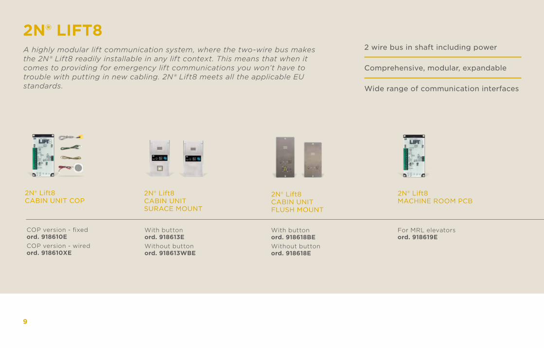
2N® LIFT8A highly modular lift communication system, where the two-wire bus makes the 2N® Lift8 readily installable in any lift context. This means that when it comes to providing for emergency lift communications you won’t have to trouble with putting in new cabling. 2N® Lift8 meets all the applicable EU standards.
2 wire bus in shaft including power
Comprehensive, modular, expandable
Wide range of communication interfaces
2N® Lift8 CABIN UNIT COP
COP version - fixedord. 918610ECOP version - wiredord. 918610XE
2N® Lift8 CABIN UNITSURACE MOUNT
With buttonord. 918613EWithout buttonord. 918613WBE
2N® Lift8 CABIN UNIT FLUSH MOUNT
With buttonord. 918618BEWithout buttonord. 918618E
2N® Lift8 MACHINE ROOM PCB
For MRL elevatorsord. 918619E
9
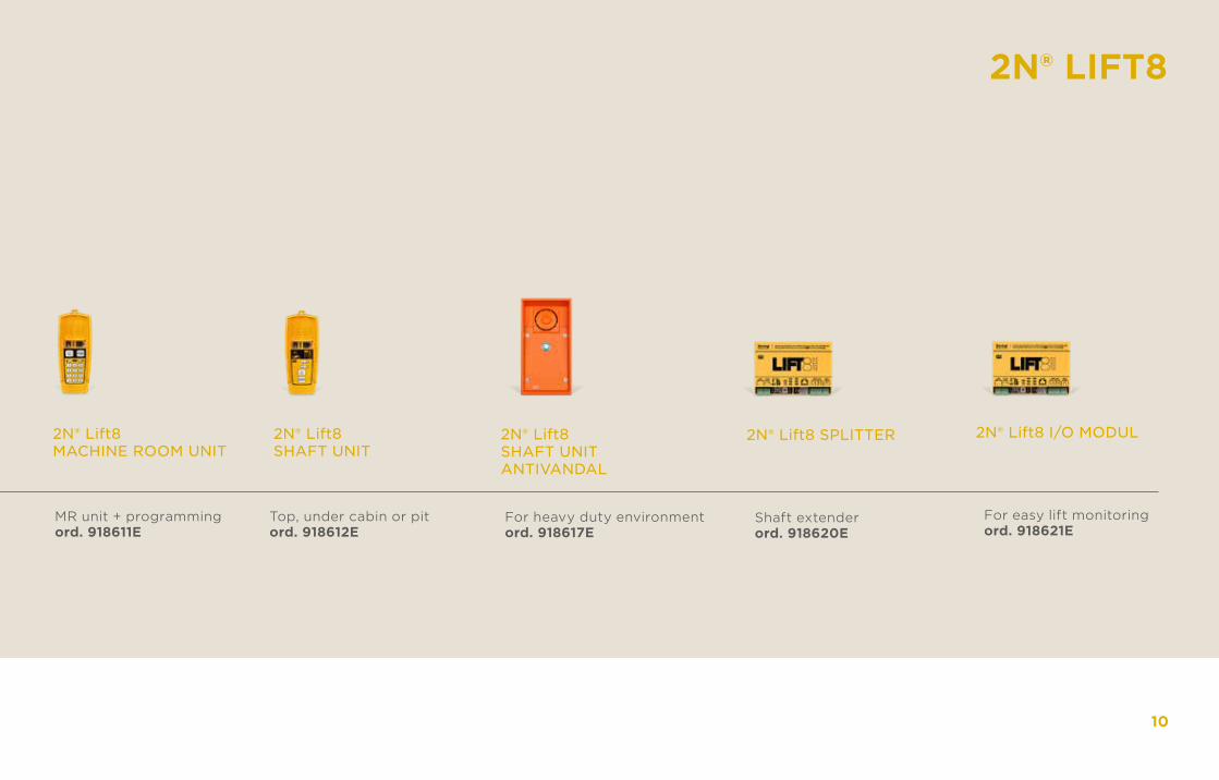
2N® Lift8 MACHINE ROOM UNIT
MR unit + programmingord. 918611E
2N® Lift8SHAFT UNIT
Top, under cabin or pitord. 918612E
2N® Lift8 SHAFT UNIT ANTIVANDAL
For heavy duty environmentord. 918617E
2N® Lift8 SPLITTER
Shaft extenderord. 918620E
2N® LIFT8
2N® Lift8 I/O MODUL
For easy lift monitoringord. 918621E
10
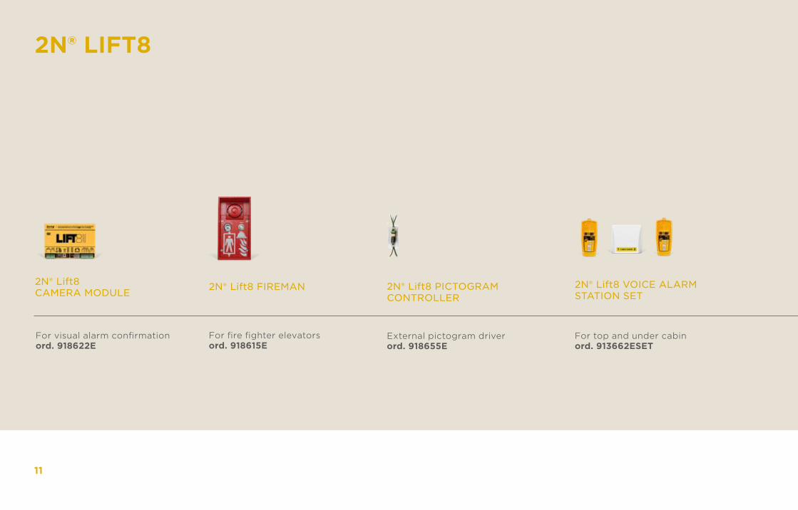
2N® Lift8 CAMERA MODULE
For visual alarm confirmationord. 918622E
2N® Lift8 FIREMAN
For fire fighter elevatorsord. 918615E
2N® Lift8 PICTOGRAM CONTROLLER
External pictogram driverord. 918655E
2N® LIFT8
2N® Lift8 VOICE ALARM STATION SET
For top and under cabinord. 913662ESET
11
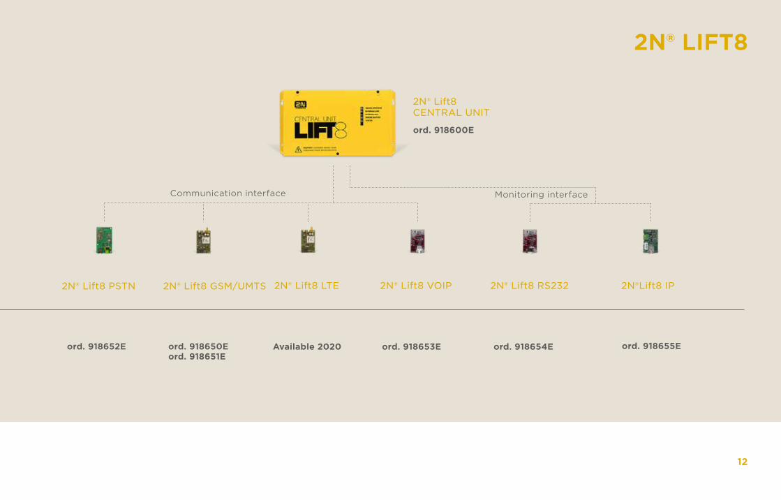
2N® Lift8 PSTN
ord. 918652E
2N® LIFT8
2N® Lift8 GSM/UMTS
ord. 918650Eord. 918651E
2N® Lift8 LTE
Available 2020
2N® Lift8 VOIP
ord. 918653E
2N®Lift8 IP
ord. 918655E
2N® Lift8 RS232
ord. 918654E
2N® Lift8 CENTRAL UNIT
ord. 918600E
12
Communication interface Monitoring interface
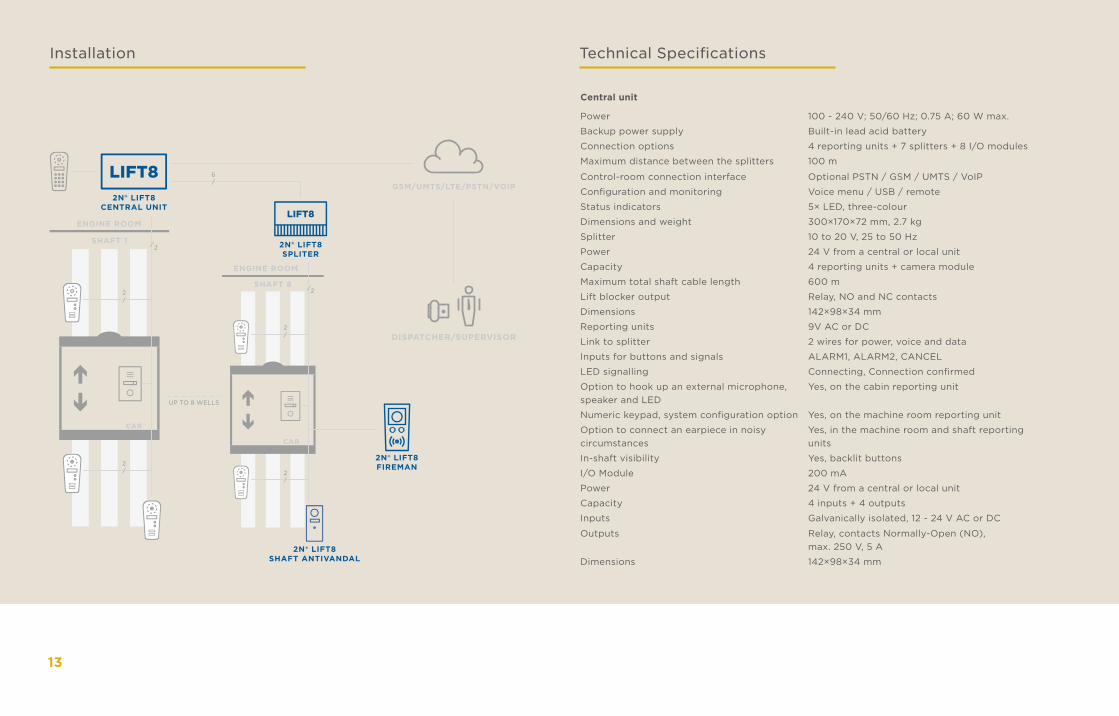
CAR
SHAFT 8
ENGINE ROOM
2/
2/
2
/
LIFT8
2N® LIFT8SPLITER
LIFT82N® LIFT8
CENTRAL UNIT
UP TO 8 WELLS
CAR
SHAFT 1
ENGINE ROOM
2/
2/
2
/
6/
GSM/UMTS/LTE/PSTN/VOIP
DISPATCHER/SUPERVISOR
2N® LIFT8FIREMAN
2N® LIFT8SHAFT ANTIVANDAL
Installation Technical Specifications
Central unit
Power 100 - 240 V; 50/60 Hz; 0.75 A; 60 W max.
Backup power supply Built-in lead acid battery
Connection options 4 reporting units + 7 splitters + 8 I/O modules
Maximum distance between the splitters 100 m
Control-room connection interface Optional PSTN / GSM / UMTS / VoIP
Configuration and monitoring Voice menu / USB / remote
Status indicators 5× LED, three-colour
Dimensions and weight 300×170×72 mm, 2.7 kg
Splitter 10 to 20 V, 25 to 50 Hz
Power 24 V from a central or local unit
Capacity 4 reporting units + camera module
Maximum total shaft cable length 600 m
Lift blocker output Relay, NO and NC contacts
Dimensions 142×98×34 mm
Reporting units 9V AC or DC
Link to splitter 2 wires for power, voice and data
Inputs for buttons and signals ALARM1, ALARM2, CANCEL
LED signalling Connecting, Connection confirmed
Option to hook up an external microphone, speaker and LED
Yes, on the cabin reporting unit
Numeric keypad, system configuration option Yes, on the machine room reporting unit
Option to connect an earpiece in noisy circumstances
Yes, in the machine room and shaft reporting units
In-shaft visibility Yes, backlit buttons
I/O Module 200 mA
Power 24 V from a central or local unit
Capacity 4 inputs + 4 outputs
Inputs Galvanically isolated, 12 - 24 V AC or DC
Outputs Relay, contacts Normally-Open (NO),max. 250 V, 5 A
Dimensions 142×98×34 mm
13
Central unit
Power 100 - 240 V; 50/60 Hz; 0.75 A; 60 W max.
Backup power supply Built-in lead acid battery
Connection options 4 reporting units + 7 splitters + 8 I/O modules
Maximum distance between the splitters 100 m
Control-room connection interface Optional PSTN / GSM / UMTS / VoIP
Configuration and monitoring Voice menu / USB / remote
Status indicators 5× LED, three-colour
Dimensions and weight 300×170×72 mm, 2.7 kg
Splitter 10 to 20 V, 25 to 50 Hz
Power 24 V from a central or local unit
Capacity 4 reporting units + camera module
Maximum total shaft cable length 600 m
Lift blocker output Relay, NO and NC contacts
Dimensions 142×98×34 mm
Reporting units 9V AC or DC
Link to splitter 2 wires for power, voice and data
Inputs for buttons and signals ALARM1, ALARM2, CANCEL
LED signalling Connecting, Connection confirmed
Option to hook up an external microphone, speaker and LED
Yes, on the cabin reporting unit
Numeric keypad, system configuration option Yes, on the machine room reporting unit
Option to connect an earpiece in noisy circumstances
Yes, in the machine room and shaft reporting units
In-shaft visibility Yes, backlit buttons
I/O Module 200 mA
Power 24 V from a central or local unit
Capacity 4 inputs + 4 outputs
Inputs Galvanically isolated, 12 - 24 V AC or DC
Outputs Relay, contacts Normally-Open (NO),max. 250 V, 5 A
Dimensions 142×98×34 mm
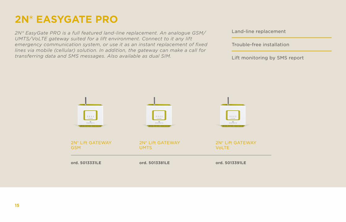
2N® EASYGATE PRO
2N® Lift GATEWAY GSM
2N® Lift GATEWAY UMTS
ord. 5013381LEord. 5013331LE
2N® EasyGate PRO is a full featured land-line replacement. An analogue GSM/UMTS/VoLTE gateway suited for a lift environment. Connect to it any lift emergency communication system, or use it as an instant replacement of fixed lines via mobile (cellular) solution. In addition, the gateway can make a call for transferring data and SMS messages. Also available as dual SIM.
Land-line replacement
Trouble-free installation
Lift monitoring by SMS report
15
2N® Lift GATEWAY VoLTE
ord. 5013391LE
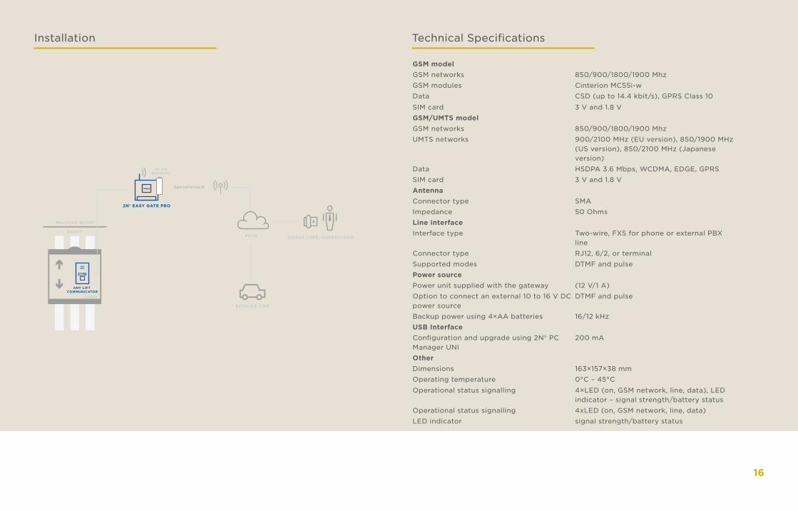
Installation Technical Specifications
GSM modelGSM networks 850/900/1800/1900 MhzGSM modules Cinterion MC55i-wData CSD (up to 14.4 kbit/s), GPRS Class 10
SIM card 3 V and 1.8 VGSM/UMTS modelGSM networks 850/900/1800/1900 MhzUMTS networks 900/2100 MHz (EU version), 850/1900 MHz
(US version), 850/2100 MHz (Japanese version)
Data HSDPA 3.6 Mbps, WCDMA, EDGE, GPRSSIM card 3 V and 1.8 VAntennaConnector type SMAImpedance 50 OhmsLine interfaceInterface type Two-wire, FXS for phone or external PBX
lineConnector type RJ12, 6/2, or terminalSupported modes DTMF and pulsePower sourcePower unit supplied with the gateway (12 V/1 A)Option to connect an external 10 to 16 V DC power source
DTMF and pulse
Backup power using 4×AA batteries 16/12 kHzUSB InterfaceConfiguration and upgrade using 2N® PC Manager UNI
200 mA
OtherDimensions 163×157×38 mmOperating temperature 0°C – 45°C
Operational status signalling 4×LED (on, GSM network, line, data), LED indicator – signal strength/battery status
Operational status signalling 4xLED (on, GSM network, line, data)LED indicator signal strength/battery status
PRO
2N® EASY GATE PRO
CABIN
SHAFT
MACHINE ROOM
PSTN DISPATCHER/SUPERVISOR
SERVICE CAR
ANY LIFT COMMUNICATOR
4X AABATTERY
GSM/UMTS/VoLTE
16
2N® EASYGATE IP
2N® EasyGateIP
2N® EasyGateIP+
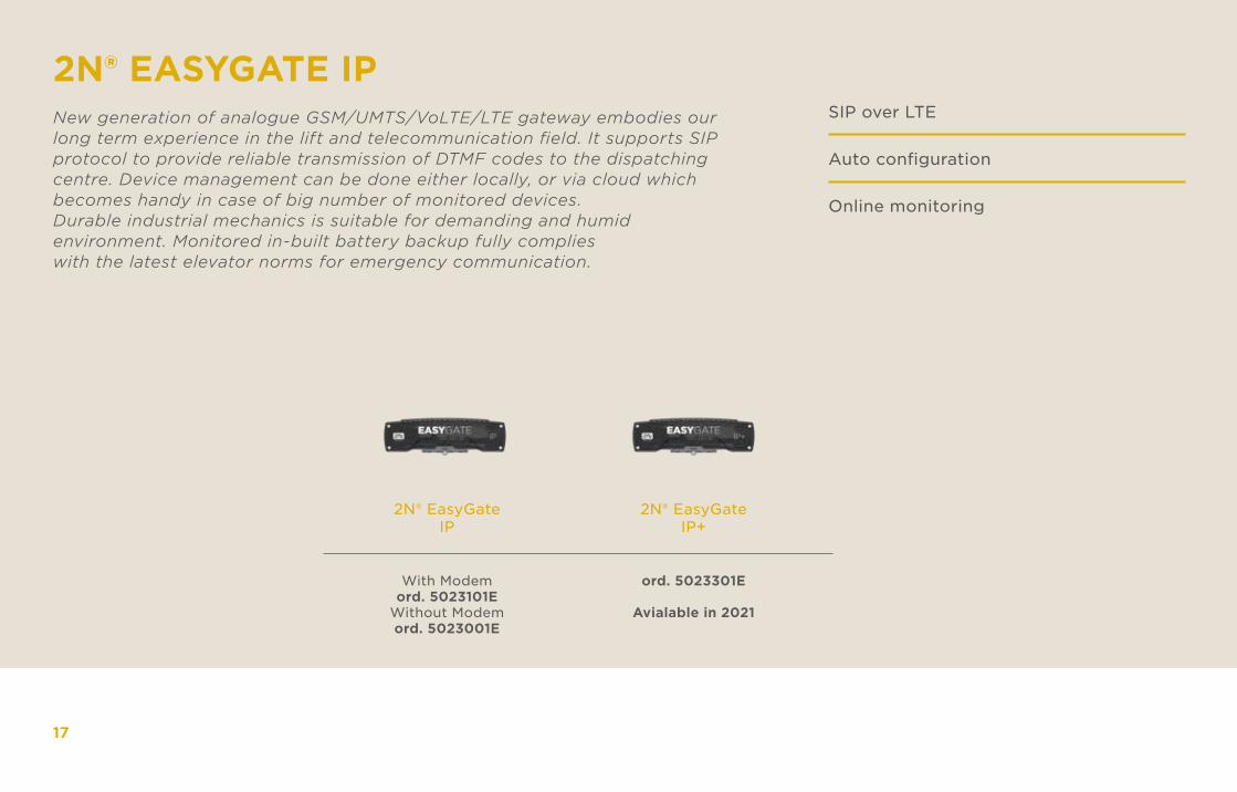
ord. 5023301E
Avialable in 2021
With Modemord. 5023101E
Without Modemord. 5023001E
New generation of analogue GSM/UMTS/VoLTE/LTE gateway embodies our long term experience in the lift and telecommunication field. It supports SIP protocol to provide reliable transmission of DTMF codes to the dispatching centre. Device management can be done either locally, or via cloud which becomes handy in case of big number of monitored devices. Durable industrial mechanics is suitable for demanding and humid environment. Monitored in-built battery backup fully complies with the latest elevator norms for emergency communication.
SIP over LTE
Auto configuration
Online monitoring
17
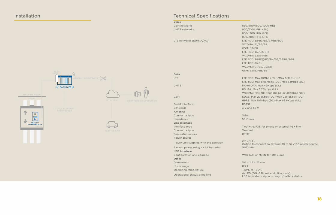
Installation Technical SpecificationsVoiceGSM networks 850/900/1800/1900 MhzUMTS networks 900/2100 MHz (EU)
850/1900 MHz (US)850/2100 MHz (JPN)
LTE networks (EU/NA/AU) LTE FDD: B1/B3/B5/B7/B8/B20WCDMA: B1/B5/B8GSM: B3/B8LTE FDD: B2/B4/B12WCDMA: B2/B4/B5LTE FDD: B1/B2①/B3/B4/B5/B7/B8/B28LTE TDD: B40WCDMA: B1/B2/B5/B8GSM: B2/B3/B5/B8
DataLTE LTE FDD: Max 10Mbps (DL)/Max 5Mbps (UL)
LTE TDD: Max 8.96Mbps (DL)/Max 3.1Mbps (UL)UMTS DC-HSDPA: Max 42Mbps (DL)
HSUPA: Max 5.76Mbps (UL)WCDMA: Max 384Kbps (DL)/Max 384Kbps (UL)
GSM EDGE: Max 296Kbps (DL)/Max 236.8Kbps (UL)GPRS: Max 107Kbps (DL)/Max 85.6Kbps (UL)
Serial Interface RS232SIM cards 3 V and 1.8 VAntennaConnector type SMAImpedance 50 OhmsLine interfaceInterface type Two-wire, FXS for phone or external PBX lineConnector type TerminalSupported modes DTMFPower source
Power unit supplied with the gateway (12 V/1 A), Option to connect an external 10 to 16 V DC power source
Backup power using 4×AA batteries 16/12 kHzUSB InterfaceConfiguration and upgrade Web GUI, or My2N for lifts cloudOtherDimensions 195 × 119 × 61 mmIP coverage IP43Operating temperature -40°C to +85°C
Operational status signalling 4×LED (ON, GSM network, line, data), LED indicator – signal strength/battery status
2N® EASYGATE IP
CABIN
SHAFT
MACHINE ROOM
OTHER ELEVATORTECHNOLOGY
PSTN/VOIP DISPATCHER/SUPERVISOR
SERVICE CAR
ANY LIFT COMMUNICATOR
4X AABATTERY
GSM/UMTS/VOLTE/LTE
18
2N® LIFTGATE
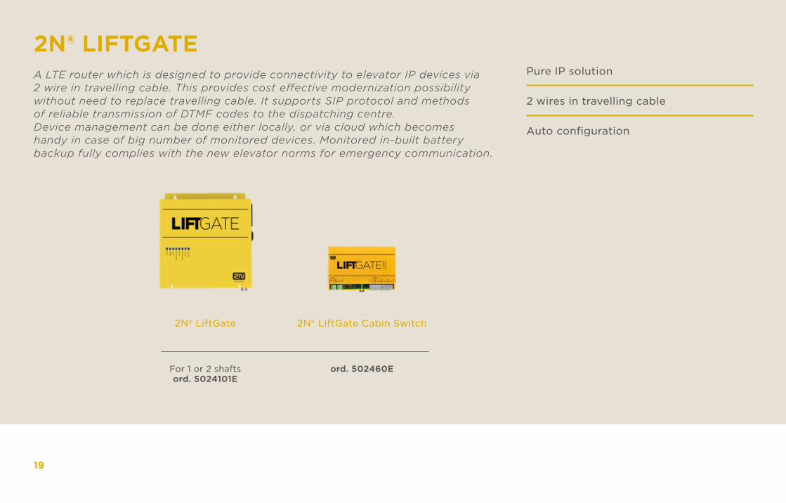
2N® LiftGate 2N® LiftGate Cabin Switch
ord. 502460E For 1 or 2 shaftsord. 5024101E
A LTE router which is designed to provide connectivity to elevator IP devices via 2 wire in travelling cable. This provides cost effective modernization possibility without need to replace travelling cable. It supports SIP protocol and methods of reliable transmission of DTMF codes to the dispatching centre. Device management can be done either locally, or via cloud which becomes handy in case of big number of monitored devices. Monitored in-built battery backup fully complies with the new elevator norms for emergency communication.
Pure IP solution
2 wires in travelling cable Auto configuration
19
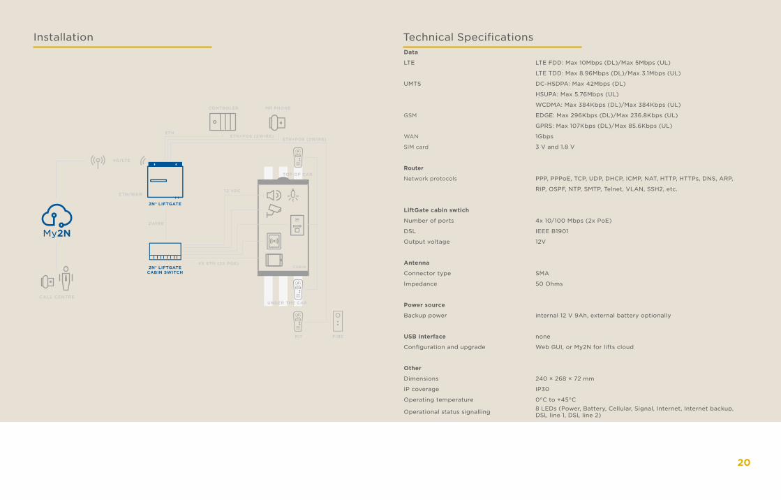
Installation Technical SpecificationsData
LTE LTE FDD: Max 10Mbps (DL)/Max 5Mbps (UL)
LTE TDD: Max 8.96Mbps (DL)/Max 3.1Mbps (UL)
UMTS DC-HSDPA: Max 42Mbps (DL)
HSUPA: Max 5.76Mbps (UL)
WCDMA: Max 384Kbps (DL)/Max 384Kbps (UL)
GSM EDGE: Max 296Kbps (DL)/Max 236.8Kbps (UL)
GPRS: Max 107Kbps (DL)/Max 85.6Kbps (UL)
WAN 1Gbps
SIM card 3 V and 1.8 V
Router
Network protocols PPP, PPPoE, TCP, UDP, DHCP, ICMP, NAT, HTTP, HTTPs, DNS, ARP,
RIP, OSPF, NTP, SMTP, Telnet, VLAN, SSH2, etc.
LiftGate cabin swtich
Number of ports 4x 10/100 Mbps (2x PoE)
DSL IEEE B1901
Output voltage 12V
Antenna
Connector type SMA
Impedance 50 Ohms
Power source
Backup power internal 12 V 9Ah, external battery optionally
USB Interface none
Configuration and upgrade Web GUI, or My2N for lifts cloud
Other
Dimensions 240 × 268 × 72 mm
IP coverage IP30
Operating temperature 0°C to +45°C
Operational status signalling 8 LEDs (Power, Battery, Cellular, Signal, Internet, Internet backup, DSL line 1, DSL line 2)
20
CABIN
TOP OF CAR
4G/LTE
ETH/WAN12 VDC
ETHETH+POE (2WIRE)
ETH+POE (2WIRE)
4X ETH (2X POE)
2WIRE
UNDER THE CARCALL CENTRE
2N® LIFTGATE
2N® LIFTGATECABIN SWITCH
CONTROLER MR PHONE
PIT FIRE
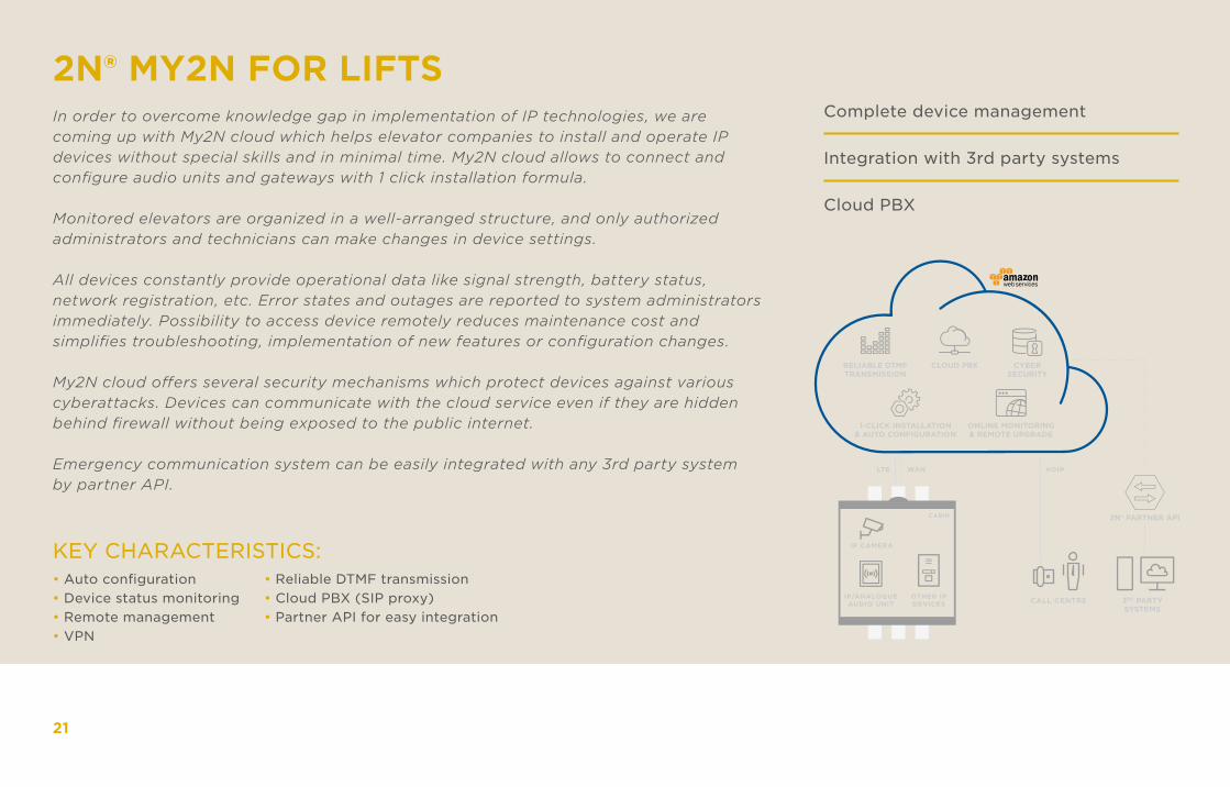
2N® MY2N FOR LIFTSIn order to overcome knowledge gap in implementation of IP technologies, we are coming up with My2N cloud which helps elevator companies to install and operate IP devices without special skills and in minimal time. My2N cloud allows to connect and configure audio units and gateways with 1 click installation formula.
Monitored elevators are organized in a well-arranged structure, and only authorized administrators and technicians can make changes in device settings.
All devices constantly provide operational data like signal strength, battery status, network registration, etc. Error states and outages are reported to system administrators immediately. Possibility to access device remotely reduces maintenance cost and simplifies troubleshooting, implementation of new features or configuration changes.
My2N cloud offers several security mechanisms which protect devices against various cyberattacks. Devices can communicate with the cloud service even if they are hidden behind firewall without being exposed to the public internet.
Emergency communication system can be easily integrated with any 3rd party system by partner API.
Complete device management
Integration with 3rd party systems
Cloud PBX
21
KEY CHARACTERISTICS:• Auto configuration• Device status monitoring• Remote management• VPN
• Reliable DTMF transmission• Cloud PBX (SIP proxy)• Partner API for easy integration
3RD PARTYSYSTEMS
2N® PARTNER APICABIN
IP CAMERA
IP/ANALOGUEAUDIO UNIT
OTHER IPDEVICES
LTE WAN VOIP
CALL CENTRE
RELIABLE DTMFTRANSMISSION
1-CLICK INSTALLATION& AUTO CONFIGURATION
ONLINE MONITORING& REMOTE UPGRADE
CLOUD PBX CYBERSECURITY
22
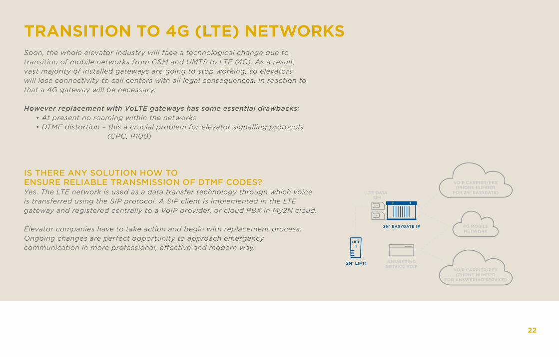
TRANSITION TO 4G (LTE) NETWORKSSoon, the whole elevator industry will face a technological change due to transition of mobile networks from GSM and UMTS to LTE (4G). As a result, vast majority of installed gateways are going to stop working, so elevators will lose connectivity to call centers with all legal consequences. In reaction to that a 4G gateway will be necessary.
However replacement with VoLTE gateways has some essential drawbacks: • At present no roaming within the networks • DTMF distortion – this a crucial problem for elevator signalling protocols (CPC, P100)
IS THERE ANY SOLUTION HOW TO ENSURE RELIABLE TRANSMISSION OF DTMF CODES?Yes. The LTE network is used as a data transfer technology through which voice is transferred using the SIP protocol. A SIP client is implemented in the LTE gateway and registered centrally to a VoIP provider, or cloud PBX in My2N cloud.
Elevator companies have to take action and begin with replacement process. Ongoing changes are perfect opportunity to approach emergency communication in more professional, effective and modern way.
2N® LIFT1
LTE DATASIM
ANSWERINGSERVICE VOIP
VOIP CARRIER/PBX(PHONE NUMBER
FOR 2N® EASYGATE)
4G MOBILENETWORK
VOIP CARRIER/PBX(PHONE NUMBER
FOR ANSWERING SERVICE)
2N® EASYGATE IP
2N LIFT SOFTWARE
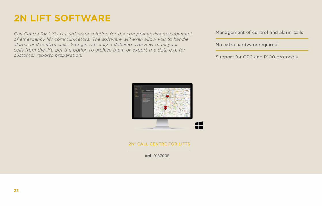
2N® CALL CENTRE FOR LIFTS
Call Centre for Lifts is a software solution for the comprehensive management of emergency lift communicators. The software will even allow you to handle alarms and control calls. You get not only a detailed overview of all your calls from the lift, but the option to archive them or export the data e.g. for customer reports preparation.
Management of control and alarm calls
No extra hardware required
Support for CPC and P100 protocols
ord. 918700E
23
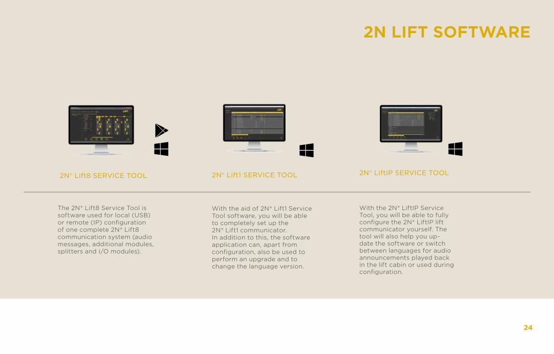
2N® Lift8 SERVICE TOOL 2N® Lift1 SERVICE TOOL 2N® LiftIP SERVICE TOOL
With the aid of 2N® Lift1 Service Tool software, you will be able to completely set up the 2N® Lift1 communicator. In addition to this, the software application can, apart from configuration, also be used to perform an upgrade and to change the language version.
The 2N® Lift8 Service Tool is software used for local (USB) or remote (IP) configuration of one complete 2N® Lift8 communication system (audio messages, additional modules, splitters and I/O modules).
With the 2N® LiftIP Service Tool, you will be able to fully configure the 2N® LiftIP lift communicator yourself. The tool will also help you up-date the software or switch between languages for audio announcements played back in the lift cabin or used during configuration.
24
2N LIFT SOFTWARE
25
LIFT ACCESSORIES
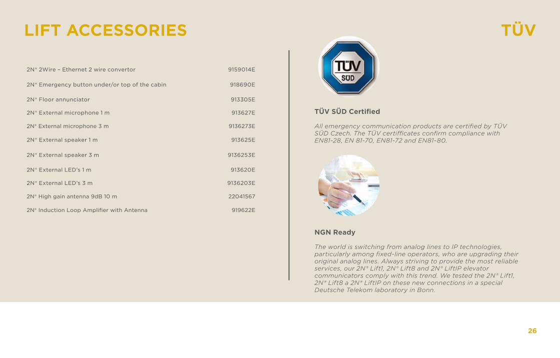
NGN Ready
The world is switching from analog lines to IP technologies, particularly among fixed-line operators, who are upgrading their original analog lines. Always striving to provide the most reliable services, our 2N® Lift1, 2N® Lift8 and 2N® LiftIP elevator communicators comply with this trend. We tested the 2N® Lift1, 2N® Lift8 a 2N® LiftIP on these new connections in a special Deutsche Telekom laboratory in Bonn.
26
TÜV SÜD Certified
All emergency communication products are certified by TÜV SÜD Czech. The TÜV certifficates confirm compliance with EN81-28, EN 81-70, EN81-72 and EN81-80.
2N® 2Wire – Ethernet 2 wire convertor 9159014E
2N® Emergency button under/or top of the cabin 918690E
2N® Floor annunciator 913305E
2N® External microphone 1 m 913627E
2N® External microphone 3 m 9136273E
2N® External speaker 1 m 913625E
2N® External speaker 3 m 9136253E
2N® External LED’s 1 m 913620E
2N® External LED’s 3 m 9136203E
2N® High gain antenna 9dB 10 m 22041567
2N® Induction Loop Amplifier with Antenna 919622E
TÜV
ELEVATOR NORMS
EN81-28
EN81-70
EN81-72
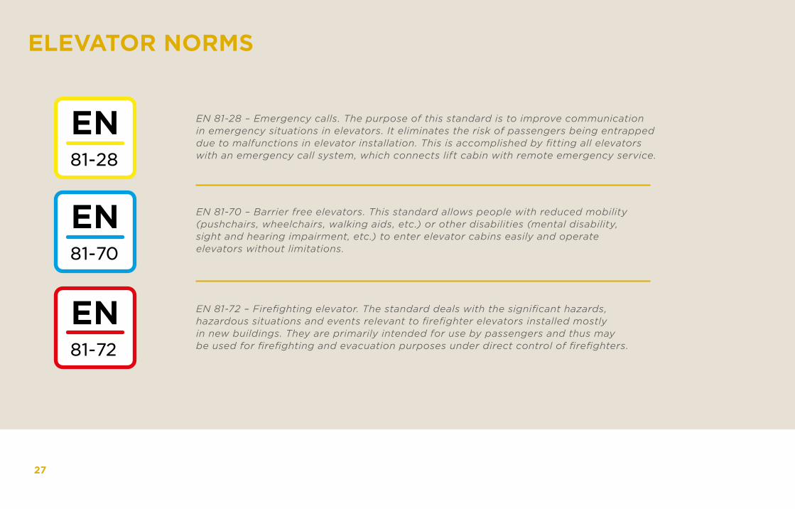
EN 81-28 – Emergency calls. The purpose of this standard is to improve communication in emergency situations in elevators. It eliminates the risk of passengers being entrapped due to malfunctions in elevator installation. This is accomplished by fitting all elevators with an emergency call system, which connects lift cabin with remote emergency service.
EN 81-70 – Barrier free elevators. This standard allows people with reduced mobility (pushchairs, wheelchairs, walking aids, etc.) or other disabilities (mental disability, sight and hearing impairment, etc.) to enter elevator cabins easily and operate elevators without limitations.
EN 81-72 – Firefighting elevator. The standard deals with the significant hazards, hazardous situations and events relevant to firefighter elevators installed mostly in new buildings. They are primarily intended for use by passengers and thus may be used for firefighting and evacuation purposes under direct control of firefighters.
27
EN81-20
EN81-71
EN81-80
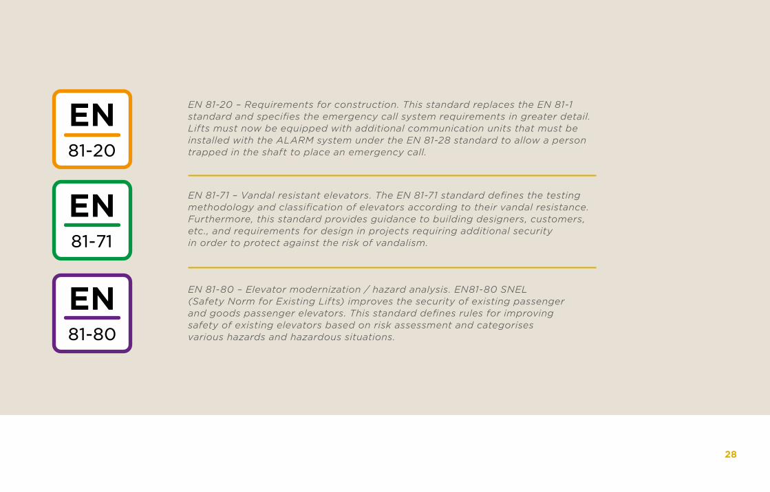
EN 81-20 – Requirements for construction. This standard replaces the EN 81-1 standard and specifies the emergency call system requirements in greater detail. Lifts must now be equipped with additional communication units that must be installed with the ALARM system under the EN 81-28 standard to allow a person trapped in the shaft to place an emergency call.
EN 81-71 – Vandal resistant elevators. The EN 81-71 standard defines the testing methodology and classification of elevators according to their vandal resistance. Furthermore, this standard provides guidance to building designers, customers, etc., and requirements for design in projects requiring additional security in order to protect against the risk of vandalism.
EN 81-80 – Elevator modernization / hazard analysis. EN81-80 SNEL (Safety Norm for Existing Lifts) improves the security of existing passenger and goods passenger elevators. This standard defines rules for improving safety of existing elevators based on risk assessment and categorises various hazards and hazardous situations.
28

2N TELEKOMUNIKACE a.s.
©2N TELEKOMUNIKACE a.s. / 2020EN_LIFT01
+ 420 261 301 500
www.2n.cz
2N Telekomunikace a.s.Modřanská 621/72143 01 Prague 4, Czech Republic