Embed Size (px)
Citation preview
IOSR Journal of Electrical and Electronics Engineering (IOSR-JEEE)
e-ISSN: 2278-1676,p-ISSN: 2320-3331, Volume 10, Issue 6 Ver. II (Nov – Dec. 2015), PP 68-77
www.iosrjournals.org
DOI: 10.9790/1676-10626877 www.iosrjournals.org 68 | Page
Smart Mutatable Advanced Technology Wheelchair
Shruti Kulkarni1, Prashali Sharma
2, Nilay Chowdhury
3,
Tanay Chowdhury4 1(U.G Student, Electronics & Telecommunication, Pune University, Maharashtra, India)
2(U.G Student, Electronics & Telecommunication, Pune University, Maharashtra, India)
3(U.G Student, Electronics & Telecommunication, Pune University Maharashtra,, India)
4(U.G Student, Electronics & Telecommunication, Pune University, Maharashtra, India)
Abstract: While the needs of many individuals with disabilities can be satisfied with power wheelchairs, some
members of the disabled community find it difficult or impossible to operate a standard power wheelchair. To
accommodate this population, several researchers have used technologies originally developed for mobile
robots to create “smart wheelchairs” that reduce the physical, perceptual, and cognitive skills necessary to
operate a power wheelchair. We are developing a Smart Mutatable Advanced Technology wheelchair. This
paper describes the design of a prototype, which has been evaluated on wheelchair.
Keywords: disability, rehabilitation, smart features, smart phone, smart wheelchair.
I. Introduction The number of people who are paralyzed and therefore dependent on others due to loss of self-mobility
is growing with the population. The development of the wheelchair for paralyzed users is surprisingly recent
starting with the conventional manually powered wheelchairs and advancing to electrical wheelchairs.
Conventional wheelchair use tends to focus exclusively on manual use of hands which excludes those unable to
do so. Diseases or accidents injuring the nervous system also affect because people lose their ability to move
their voluntary muscle. Because voluntary muscle is the main actuator enabling people to move their body,
paralysis may cause a person not move their loco motor organ such as arm, leg and others.
Scientist Stephen W. Hawking is perhaps the most well-known victim of major paralysis – Hawking
was diagnosed with incurable Amyotrophic Lateral Sclerosis (ALS) in 1962, thereafter using a wheelchair to
move. Many of those suffering close to or complete paralysis usually however still can control their eye
movement which inspired us to develop an eye-controlled electric wheelchair.
(a) Alex Dev, Horizon C Chacko (2011) used EOG to control the wheelchair locomotion. A pair of
electrodes is placed horizontally to left and right Eye. If the eye is moved from the centre position
towards one electrode, a potential change occurs between the electrodes. Due to the changes in the
potential the wheelchair can be controlled.
(b) S.Tameemsultana and N. Kali Saranya (2011) [1] used head and finger movement for wheelchair
locomotion. In finger movement they use flex sensor, placed on the finger. It is an analog resistor usually in the
form of strip long variable resistance. Due to the bending of finger the resistance varies which controls the
locomotion of the wheelchair. Bending the sensor at one point more than 90 may permanently damage the
sensor which is a main drawback. The system already existing for the physically challenged person controlled
by other different technologies has some defects:
In Eye ball sensor they use infra red sensor to control the wheelchair where continuous fall of IR
radiation in the eye causes irritation to the patient (Alex Dev, Horizon C Chacko and Roshan Varghese,
April, 2012, ISBN.)
In voice control the person must use the exact commands only to control the movement. Change in the
words restricts the wheelchair movement (Manuel Mazo, 1995) [2]. All the electronic system and also
the philosophy for functioning has been sufficiently refined to attain the subsequent performances:
- To ensure easy, comfortable driving.
- To reply to the speed requirements for a system of this kind (maximum speeds of up to three m/s).
- To be simply adaptable to any kind of commercial wheelchair chassis.
- To ease learning to handle the chair and getting most potency.
- To ensure much constant speeds, to an oversized extent independently of the characteristics of the
surface over that the wheel chair is moving (greater or lesser roughness of the ground and also slope of
same) and the weight of the person using it.
Keeping in mind our aim of helping patients in all aspects, study was conducted to determine how to
collaborate easy functioning wheelchair with low cost. Hence a wheelchair was developed rounding off all
possible considerations to get a complete package of simple design, low cost and user friendly operations.

Smart Mutatable Advanced Technology Wheelchair
DOI: 10.9790/1676-10626877 www.iosrjournals.org 69 | Page
The self propelled part of conventional wheelchair was removed and replaced by smart features. The
joystick operative mode was replaced by touch mode wherein user can navigate by giving touch inputs
to a smart phone.
The wheelchair consists of gesture based movement which counters various forms of paralysis or if the
patient is unable to control the chair with fingers.
The third mode is voice incorporated for patients who are physically disabled or have musculoskeletal
problems.
For patients who are blind or have neurological issues, computer controlled mode is available wherein
a host computer monitors all the movement of chair. The location of chair with visuals is obtained
through smart phone/camera mounted on chair. Also if patient falls ill suddenly while travelling; the
location of patient along with his position is sent through GSM to emergency smart phone and PC
mode can be enabled just by pairing up with the required id and patient can be taken to a safe place.
Unlike all wheelchair products in market, this wheelchair does not just travels on flat, rough or slopes.
It has reliable mechanism to climb/de-climb stairs without any effort by user or external human. This
wheelchair is robust enough to carry the user through urban as well as rural pathways overcoming all
types of obstacles.
The wheelchair consists of three modifiable positions which includes chair position, bed position &
relax position. The bed position helps the patient‟s burden to be reduced while being shifted from
wheelchair to bed while sleeping; or in case there is bed shortage at paraplegic centre‟s. The chair
position is the conventional position while relax position is for user‟s comfort to read books, watch TV,
etc. A timely medication reminder facility is also made available for patient‟s personal health care.
The smart phone technology has significantly affected the lives of human and hence this technology
has been implemented as an integral part of this wheelchair as smart phones are available with at least 4.77
billion members across the globe. Smart features have been included to counteract various difficulties faced by a
conventional wheelchair user. Overall this wheelchair system can prove to be beneficial for all grades of people
in all fields relating to military, hospitals, paraplegic centre‟s or even domestically or during disastrous
situations like earthquake thereby making a patient totally self-reliant and self-dependent with high reliability,
comfort, care, assistance & optimal low cost.
II. Proposed Methodology 2.1 HARDWARE DESCRIPTION
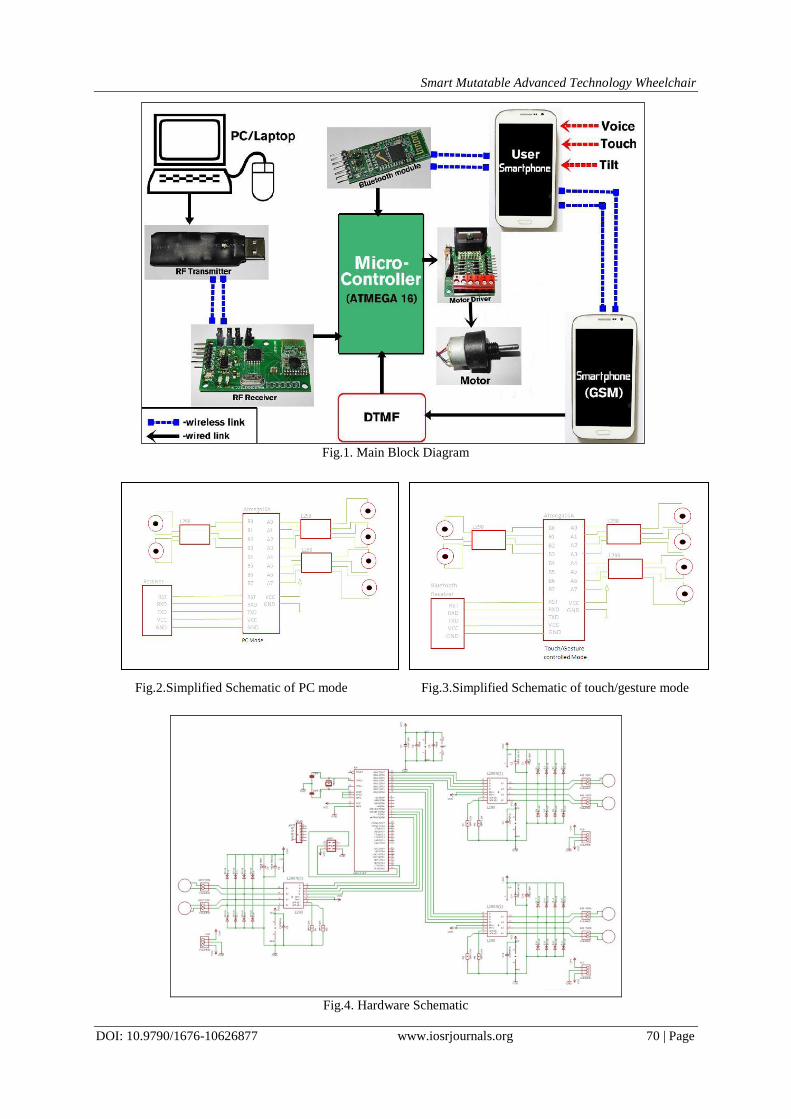
The basic structure of our project consists of microcontroller, motor driver, smart phone, PC/Laptop,
power supply and motors. The main aim of this project is construction of wheelchair having a direction
control through voice commands, touches or hand gesture.
The touchpad comprises a smart phone. When pressure is applied to the capacitive screen of smart
phone, an XY co-ordinate location is produced and transmitted with Bluetooth available on smart
phone to Bluetooth module (HC-05) available on wheelchair and the wheelchair will move in the
desired direction.
A change in location of the pressure will result in a corresponding change in direction .The touchpad
also has a neutral or no movement point which will ensure efficient braking. This is very helpful for
paralyzed and physically challenged people.
Similarly, voice commands can be used as input to a decoder which converts a particular frequency of
voice into digital bits for controller to process it and take desired action. Using voice operative mode
the user can operate the wheelchair using pre-decided voice commands. The voice commands will be
transmitted via Bluetooth available on smart phones.
In hand gesture mode the user will be able to manipulate the wheelchair using hand movements. This is
achieved by using accelerometer sensor available on smart phone which are used for gesture gaming.
The data, as above, will be transmitted via Bluetooth. In automatic mode, the wheelchair is controlled
by a host PC to traverse the route. This is very helpful to navigate in places such as home or where user
is fully paralyzed. This feature can also be efficiently used if the patient feels ill and cannot regulate the
wheelchair himself/herself. The patient will thereby be leaded to his/her home or paraplegic centre
safely.
Smart Mutatable Advanced Technology Wheelchair
DOI: 10.9790/1676-10626877 www.iosrjournals.org 70 | Page
Fig.1. Main Block Diagram
Fig.4. Hardware Schematic
Fig.2.Simplified Schematic of PC mode Fig.3.Simplified Schematic of touch/gesture mode
Smart Mutatable Advanced Technology Wheelchair
DOI: 10.9790/1676-10626877 www.iosrjournals.org 71 | Page
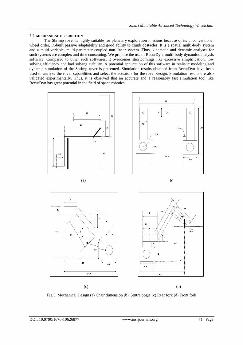
2.2 MECHANICAL DESCRIPTION
The Shrimp rover is highly suitable for planetary exploration missions because of its unconventional
wheel order, in-built passive adaptability and good ability to climb obstacles. It is a spatial multi-body system
and a multi-variable, multi-parameter coupled non-linear system. Thus, kinematic and dynamic analyses for
such systems are complex and time consuming. We propose the use of RecurDyn, multi-body dynamics analysis
software. Compared to other such softwares, it overcomes shortcomings like excessive simplification, low
solving efficiency and bad solving stability. A potential application of this software in realistic modeling and
dynamic simulation of the Shrimp rover is presented. Simulation results obtained from RecurDyn have been
used to analyze the rover capabilities and select the actuators for the rover design. Simulation results are also
validated experimentally. Thus, it is observed that an accurate and a reasonably fast simulation tool like
RecurDyn has great potential in the field of space robotics.
Fig.5. Mechanical Design (a) Chair dimension (b) Centre bogie (c) Rear fork (d) Front fork
(a) (b)
(c) (d)
Smart Mutatable Advanced Technology Wheelchair
DOI: 10.9790/1676-10626877 www.iosrjournals.org 72 | Page
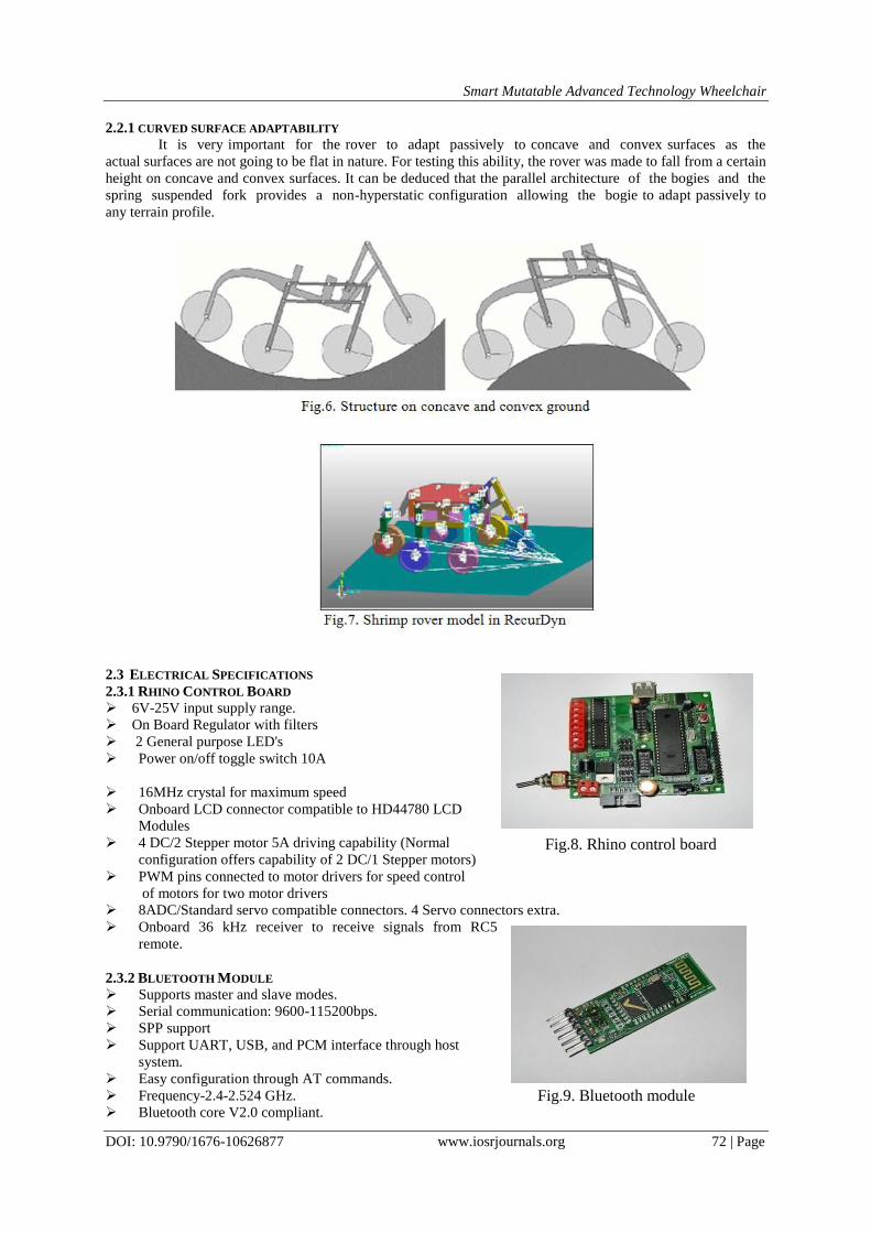
2.2.1 CURVED SURFACE ADAPTABILITY
It is very important for the rover to adapt passively to concave and convex surfaces as the
actual surfaces are not going to be flat in nature. For testing this ability, the rover was made to fall from a certain
height on concave and convex surfaces. It can be deduced that the parallel architecture of the bogies and the
spring suspended fork provides a non-hyperstatic configuration allowing the bogie to adapt passively to
any terrain profile.
2.3 ELECTRICAL SPECIFICATIONS
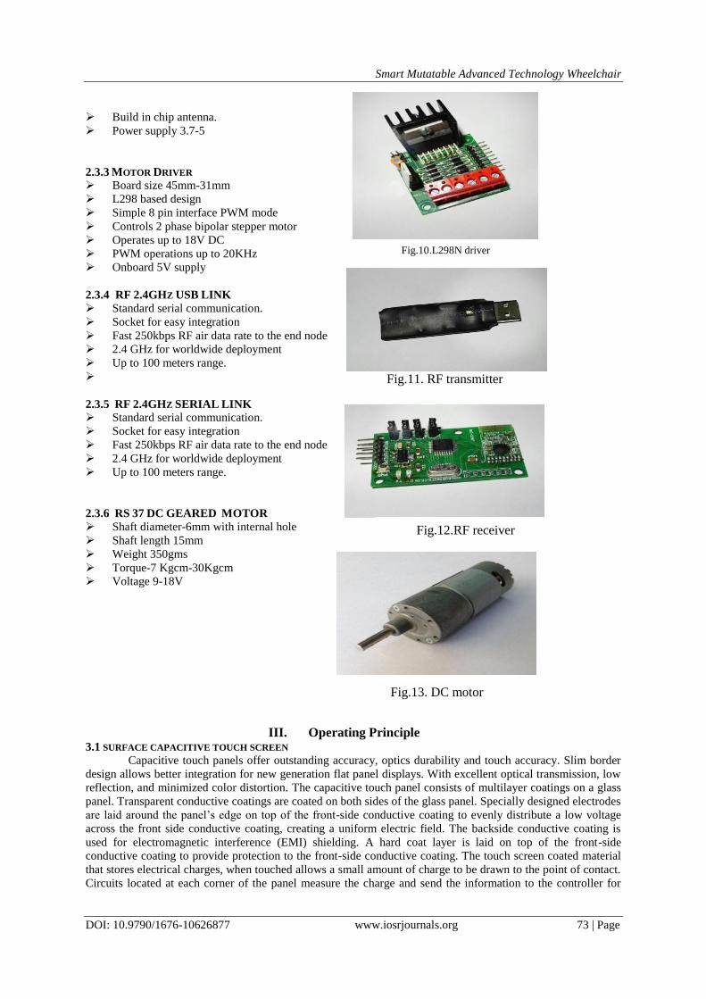
2.3.1 RHINO CONTROL BOARD
6V-25V input supply range.
On Board Regulator with filters
2 General purpose LED's
Power on/off toggle switch 10A
16MHz crystal for maximum speed
Onboard LCD connector compatible to HD44780 LCD
Modules
4 DC/2 Stepper motor 5A driving capability (Normal
configuration offers capability of 2 DC/1 Stepper motors)
PWM pins connected to motor drivers for speed control
of motors for two motor drivers
8ADC/Standard servo compatible connectors. 4 Servo connectors extra.
Onboard 36 kHz receiver to receive signals from RC5
remote.
2.3.2 BLUETOOTH MODULE
Supports master and slave modes.
Serial communication: 9600-115200bps.
SPP support
Support UART, USB, and PCM interface through host
system.
Easy configuration through AT commands.
Frequency-2.4-2.524 GHz.
Bluetooth core V2.0 compliant.
Fig.8. Rhino control board
Fig.9. Bluetooth module
Smart Mutatable Advanced Technology Wheelchair
DOI: 10.9790/1676-10626877 www.iosrjournals.org 73 | Page
Build in chip antenna.
Power supply 3.7-5
2.3.3 MOTOR DRIVER
Board size 45mm-31mm
L298 based design
Simple 8 pin interface PWM mode
Controls 2 phase bipolar stepper motor
Operates up to 18V DC
PWM operations up to 20KHz
Onboard 5V supply
2.3.4 RF 2.4GHZ USB LINK
Standard serial communication.
Socket for easy integration
Fast 250kbps RF air data rate to the end node
2.4 GHz for worldwide deployment
Up to 100 meters range.
2.3.5 RF 2.4GHZ SERIAL LINK
Standard serial communication.
Socket for easy integration
Fast 250kbps RF air data rate to the end node
2.4 GHz for worldwide deployment
Up to 100 meters range.
2.3.6 RS 37 DC GEARED MOTOR
Shaft diameter-6mm with internal hole
Shaft length 15mm
Weight 350gms
Torque-7 Kgcm-30Kgcm
Voltage 9-18V
III. Operating Principle 3.1 SURFACE CAPACITIVE TOUCH SCREEN
Capacitive touch panels offer outstanding accuracy, optics durability and touch accuracy. Slim border
design allows better integration for new generation flat panel displays. With excellent optical transmission, low
reflection, and minimized color distortion. The capacitive touch panel consists of multilayer coatings on a glass
panel. Transparent conductive coatings are coated on both sides of the glass panel. Specially designed electrodes
are laid around the panel‟s edge on top of the front-side conductive coating to evenly distribute a low voltage
across the front side conductive coating, creating a uniform electric field. The backside conductive coating is
used for electromagnetic interference (EMI) shielding. A hard coat layer is laid on top of the front-side
conductive coating to provide protection to the front-side conductive coating. The touch screen coated material
that stores electrical charges, when touched allows a small amount of charge to be drawn to the point of contact.
Circuits located at each corner of the panel measure the charge and send the information to the controller for
Fig.10.L298N driver
Fig.11. RF transmitter
Fig.13. DC motor
Fig.12.RF receiver
Smart Mutatable Advanced Technology Wheelchair
DOI: 10.9790/1676-10626877 www.iosrjournals.org 74 | Page
processing. Capacitive touch screen panels must be touched with a finger unlike resistive and surface wave
panels that can use fingers and stylus.
Fig.14. Layered structure of touch screen
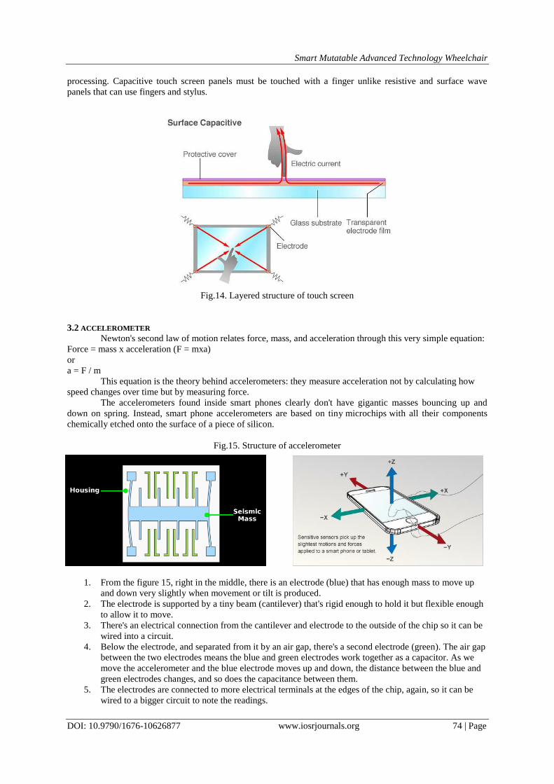
3.2 ACCELEROMETER
Newton's second law of motion relates force, mass, and acceleration through this very simple equation:
Force = mass x acceleration (F = mxa)
or
a = F / m
This equation is the theory behind accelerometers: they measure acceleration not by calculating how
speed changes over time but by measuring force.
The accelerometers found inside smart phones clearly don't have gigantic masses bouncing up and
down on spring. Instead, smart phone accelerometers are based on tiny microchips with all their components
chemically etched onto the surface of a piece of silicon.
Fig.15. Structure of accelerometer
1. From the figure 15, right in the middle, there is an electrode (blue) that has enough mass to move up
and down very slightly when movement or tilt is produced.
2. The electrode is supported by a tiny beam (cantilever) that's rigid enough to hold it but flexible enough
to allow it to move.
3. There's an electrical connection from the cantilever and electrode to the outside of the chip so it can be
wired into a circuit.
4. Below the electrode, and separated from it by an air gap, there's a second electrode (green). The air gap
between the two electrodes means the blue and green electrodes work together as a capacitor. As we
move the accelerometer and the blue electrode moves up and down, the distance between the blue and
green electrodes changes, and so does the capacitance between them.
5. The electrodes are connected to more electrical terminals at the edges of the chip, again, so it can be
wired to a bigger circuit to note the readings.
Smart Mutatable Advanced Technology Wheelchair
DOI: 10.9790/1676-10626877 www.iosrjournals.org 75 | Page
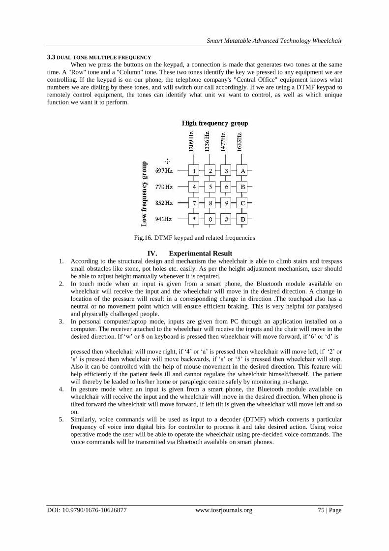
3.3 DUAL TONE MULTIPLE FREQUENCY
When we press the buttons on the keypad, a connection is made that generates two tones at the same
time. A "Row" tone and a "Column" tone. These two tones identify the key we pressed to any equipment we are
controlling. If the keypad is on our phone, the telephone company's "Central Office" equipment knows what
numbers we are dialing by these tones, and will switch our call accordingly. If we are using a DTMF keypad to
remotely control equipment, the tones can identify what unit we want to control, as well as which unique
function we want it to perform.
Fig.16. DTMF keypad and related frequencies
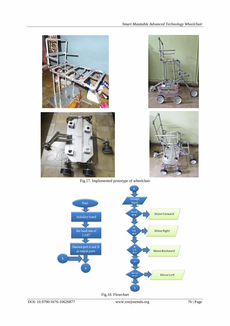
IV. Experimental Result 1. According to the structural design and mechanism the wheelchair is able to climb stairs and trespass
small obstacles like stone, pot holes etc. easily. As per the height adjustment mechanism, user should
be able to adjust height manually whenever it is required.
2. In touch mode when an input is given from a smart phone, the Bluetooth module available on
wheelchair will receive the input and the wheelchair will move in the desired direction. A change in
location of the pressure will result in a corresponding change in direction .The touchpad also has a
neutral or no movement point which will ensure efficient braking. This is very helpful for paralysed
and physically challenged people.
3. In personal computer/laptop mode, inputs are given from PC through an application installed on a
computer. The receiver attached to the wheelchair will receive the inputs and the chair will move in the
desired direction. If „w‟ or 8 on keyboard is pressed then wheelchair will move forward, if „6‟ or „d‟ is
pressed then wheelchair will move right, if „4‟ or „a‟ is pressed then wheelchair will move left, if „2‟ or
„s‟ is pressed then wheelchair will move backwards, if „s‟ or „5‟ is pressed then wheelchair will stop.
Also it can be controlled with the help of mouse movement in the desired direction. This feature will
help efficiently if the patient feels ill and cannot regulate the wheelchair himself/herself. The patient
will thereby be leaded to his/her home or paraplegic centre safely by monitoring in-charge.
4. In gesture mode when an input is given from a smart phone, the Bluetooth module available on
wheelchair will receive the input and the wheelchair will move in the desired direction. When phone is
tilted forward the wheelchair will move forward, if left tilt is given the wheelchair will move left and so
on.
5. Similarly, voice commands will be used as input to a decoder (DTMF) which converts a particular
frequency of voice into digital bits for controller to process it and take desired action. Using voice
operative mode the user will be able to operate the wheelchair using pre-decided voice commands. The
voice commands will be transmitted via Bluetooth available on smart phones.
Smart Mutatable Advanced Technology Wheelchair
DOI: 10.9790/1676-10626877 www.iosrjournals.org 76 | Page
Fig.17. Implemented prototype of wheelchair
Fig.18. Flowchart
Smart Mutatable Advanced Technology Wheelchair
DOI: 10.9790/1676-10626877 www.iosrjournals.org 77 | Page
V. Conclusion This innovative project will come in handy for various people around the world who can‟t walk or are
partially handicapped & are blind. The design structured for this wheelchair is a comfortable one where the
patient will have no issues with comfort. Overall this wheelchair has the ability to travel anywhere with no
human efforts except giving it direction controls. It operates on battery which can be recharged. We have
described the system which is driven by the latest up growing technologies and advanced algorithms. Though
main focus is on human-machine system interface, further advancements can be done through more research.
The interface and software can be modified and re-developed according to the need in future. Further
advancement in the wheelchair are possible by decreasing the power requirements of the wheel chair or finding
a way to automatically charge the battery with the help of motion of the wheel chair or solar panel.
Acknowledgement We would like to extend our sincere & heartfelt obligation towards Mr. Bendre (Owner of Bendre
Fabrications), Mrs. R.S. Kamathe (HOD & Assistant Professor, PES MCOE), Mrs. A.P. Laturkar (Assistant
professor, project coordinator & guide, PES MCOE) and Mrs. M.S. Kanitkar (Assistant professor & project
coordinator, PES MCOE) of Electronics & Telecommunication department for their active guidance, help,
cooperation & encouragement. We would also like to thank Mr. D. T. Sharma and Mrs. K. Sharma for their
constant and precious help and support towards the accomplishment of the project.
References [1] S. Tameemsultana and N. Kali Saranya, “Implementation of Head and Finger Movement Based Automatic Wheel Chair”, Bonfring
International Journal of Power Systems and Integrated Circuits, vol. 1, Special Issue, pp 48-51, December 2011.
[2] Manuel Mazo, Francisco J. Rodriguez, Jose L, Lazaro, Jesus Urena, Juan C. Garcia, Enrique Santiso, Pedro Revenga and J. Jesus
Garcia, “Wheelchair for Physically Disabled People with Voice, Ultrasonic and Infrared Sensor Control “, Autonomous Robots, vol.2, no. 3, pp. 203-224 ,Sep 1995.
[3] Ali Meghdari, F. Amiri, A. Baghani, H. Mahboubi, A. Lotfi, Y. Khalighi, R. Karimi, H. Nejat, M. Amirian, S. Kamali, and S.
Moradi, ”CEDRA”, July 2003,RoboCup Rescue Robot League Competition Awardee Paper. [4] Sandeep H.Deshmukh,Devesh Yadav & Binni Chowalloor,”Development of stair climbing transporter”, December 12-13 2007,13th
National Conference on Mechanisms and Machines (NaCoMM07).
[5] Ritika Pahuja, Narender Kumar,”Android Mobile Phone Controlled Bluetooth Robot using 8051 Microcontroller”, July 2014, Volume 2 Issue 7, International Journal of Scientific Engineering and Research (IJSER).
[6] Tabasum Shaikh, Naseem Farheen Sayyed, Shaheen Pathan, “Review of Multilevel Controlled Wheelchair”, 4th National
Conference On Electronic Technologies, pp. 275-279, April 2013. [7] Chandika T.Mohanraj, “Automation and Emerging Technology Development of 2d Seed Sowing Robo”, Journal of Agricultural
Science, vol. 1, no.1, June 2009.
[8] Vasundhara G. Posugade, Komal K. Shedge, Chaitali S. Tikhe, “Touch-Screen Based Wheelchair System”, International Journal of Engineering Research and Applications ,vol. 2, issue 2, pp.1245-1248 , Mar-Apr 2012.