Embed Size (px)
Citation preview

Smart Electricity Metering System for greenhouseconscious homes Ryan Alexander
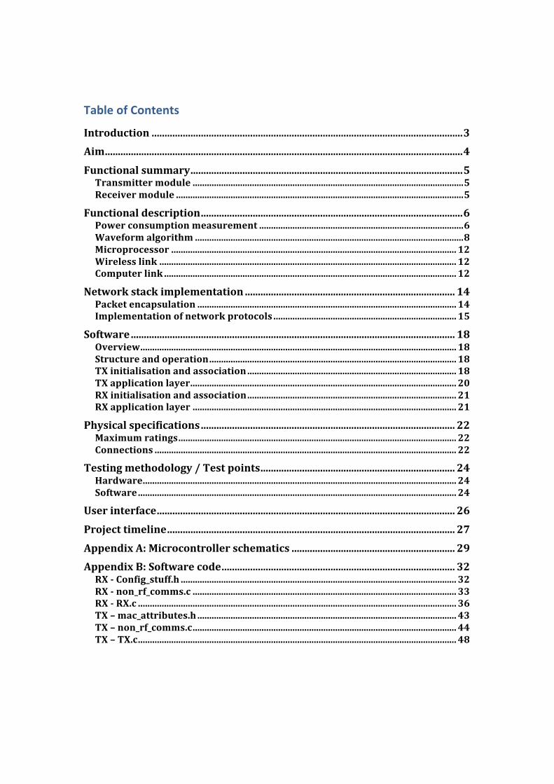
Table of Contents
Introduction ........................................................................................................................3 Aim..........................................................................................................................................4
Functional summary.........................................................................................................5 Transmitter module ..................................................................................................................5 Receiver module .........................................................................................................................5
Functional description.....................................................................................................6 Power consumption measurement ......................................................................................6 Waveform algorithm .................................................................................................................8 Microprocessor ........................................................................................................................ 12 Wireless link ............................................................................................................................. 12 Computer link ........................................................................................................................... 12
Network stack implementation ................................................................................. 14 Packet encapsulation ............................................................................................................. 14 Implementation of network protocols ............................................................................. 15
Software............................................................................................................................. 18 Overview..................................................................................................................................... 18 Structure and operation........................................................................................................ 18 TX initialisation and association........................................................................................ 18 TX application layer................................................................................................................ 20 RX initialisation and association........................................................................................ 21 RX application layer ............................................................................................................... 21
Physical specifications.................................................................................................. 22 Maximum ratings..................................................................................................................... 22 Connections ............................................................................................................................... 22
Testing methodology / Test points........................................................................... 24 Hardware.................................................................................................................................... 24 Software...................................................................................................................................... 24
User interface................................................................................................................... 26
Project timeline............................................................................................................... 27
Appendix A: Microcontroller schematics ............................................................... 29 Appendix B: Software code.......................................................................................... 32 RX Config_stuff.h .................................................................................................................... 32 RX non_rf_comms.c ............................................................................................................... 33 RX RX.c ...................................................................................................................................... 36 TX – mac_attributes.h ............................................................................................................. 43 TX – non_rf_comms.c............................................................................................................... 44 TX – TX.c...................................................................................................................................... 48

Introduction Over the past twelve months, the world has seen an exponential increase in the awareness of climate change and how it will affect society and the environment. In particular, attention has only recently become focused on what structural changes are required in the domestic, commercial and industrial environments in order to mitigate the effects of climate change. The main cause of climate change has been identified as the increasing quantity of carbon dioxide in the Earth's atmosphere. According to the Australian Bureau of Statistics, electricity use accounts for 27% of carbon dioxide emissions in Australia, a figure which has grown by 42% since 1990. It is therefore essential that carbon emissions are reduced from electricity use, either through carbon‐neutral electricity generation technologies or savings through energy efficiency. The aim of this project is to create a device which will help homeowners and businesses identify wasteful energy usage in their homes and offices, thereby reducing electricity use by raising awareness of power consumption and helping Australia move towards a more sustainable future.
These needs have arisen as a response to two separate markets which have demonstrated a demand for such a device: the domestic homeowners market and the energy auditing and reporting industry. The latter is a growing market driven by the need for businesses to become increasingly conscious of their carbon footprint. One of the main drivers for this new need is the Federal Government’s National Greenhouse and Energy Reporting System, which is due to be implemented in stages from mid‐2008. This will require corporations to audit the equivalent carbon dioxide emissions of their business activities in order to provide a streamlined, national framework for emissions reporting. A key component of this system will be a method of monitoring and recording electricity usage in commercial operations.
Simultaneously, the Federal Government, following the lead of the Victorian Government's Department of Primary Industries (DPI), has committed to a roll‐out of electricity smart meters across the country beginning in 2009 and continuing until 2012 (the ‘Advanced Metering Infrastructure’ program1). These meters, to be installed in all domestic, commercial and industrial properties, will allow remote reading of electricity consumption in discrete intervals, rather than the current accumulation meters which are monitored every three to six months. Apart from the cost savings in relation to remote reading of meters, it is hoped that their implementation will raise awareness of energy consumption and encourage energy efficiency and demand‐side participation in the national energy market.
1 http://www.dpi.vic.gov.au/dpi/dpinenergy.nsf/ at 12/4/2008

Both of these drivers are contributing to further innovation in the energy monitoring and auditing sector. More products are required to provide services which allow home‐owners and commercial bodies to further understand their carbon footprint and take action to mitigate their impact on climate change.
Aim To design, develop and implement an electricity metering device for home or commercial use which transmits data to a display for use in energy monitoring and auditing.
Functional summary
V and I signals ADC
AVRmega8
ZigBee RF230
Op-Amp (2) SPI (3)
Load
Transformers(2)
Test point 1 Test point 2
Test point 5
ZigBee RF230 AVRmega8 MAX232
SPI (3) USART (3)
Computer
RS232
Test point 2
Test point 4
Test point 3
Receiver module
Transmitter module
Functional description
Power consumption measurement The Smart Meter measures both the current and voltage of the test circuit. Using instrument transformers, the test circuit characteristics can be measured non‐invasively. The resulting analog signals are fed into an LM348 op amp configured as a summer circuit to scale the signals down to a 0‐5v logic level. This provides an interface into the Atmel AVRmega8 microprocessor, where both current and voltage signals are input into two channels of the on‐board 10‐bit ADC.
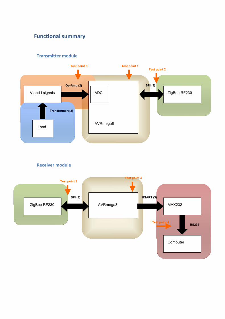
The functional specification for the Smart Meter required it to measure a circuit operating at no more than 12v AC, in order to mitigate the potential for hazardous electric shocks. In order to measure a voltage of such a circuit, a transformer was used to provide electrical isolation from the primary circuit. This ensured that the sensitive microprocessors on the PCB were not directly exposed to the primary circuit.
The configuration of the voltage transformer and the op‐amp is shown above. As the voltage from the voltage transformer oscillates from a positive voltage to a negative voltage, it must have an offset added to it to allow it to interface to the op‐amp, which can only measure voltages within its voltage supply range of 0‐5v. To acheive this, the op‐amp is configured as a summer circuit which sums together the voltages present at its + input. One of the input voltages is the signal from the voltage transformer. The voltage emanates from the voltage transformer’s centre tap and is halved using a voltage divider circuit, lowering it
Fig 1: Voltage measurement circuit

by a further factor of two. The other input voltage is a reference voltage provided by another voltage divider circuit, which remains constant at 2.5v. This offset, or bias voltage, represents 0v at the voltage transformer output. When the test circuit is enabled, the output of the op‐amp will swing between 0v and 5v, which allows it to interface to the Atmel AVRmega8’s ADC.
There were multiple possible configurations for measuring current in the test circuit. A load resistor could be used in series with the test load to convert the current information into voltage information. However, this would result in unnecessary losses in the load resistor and also present a shock hazard if the load inadvertently disconnected from the circuit. A Hall effect sensor was considered, as it requires no contact with the test circuit; it detects the voltage
Fig 2: Current waveform at A (lower line) and at B (higher line)
Fig 3: Current measurement circuit
induced along a strip of metal.
However, the current measurement circuit is similarly configured to the voltage measurement circuit. It utilises a Talerma AC1005 current transformer which is rated to measure up to 10A in the primary circuit. The current transformer produces a corresponding ‐2.5v to 2.5v voltage swing at its outputs which is summed with a bias voltage to produce a 0‐5v signal range as above.
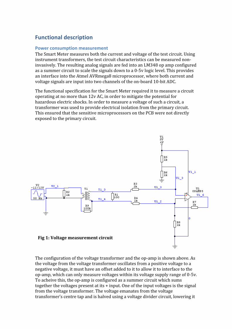
Waveform algorithm
• Waveform Analysis
In order to calculate the instantaneous power consumption of the test circuit, it is necessary to determine the voltage and current at any given time. In general, for sinusoidally‐varying voltage and current waveforms, this can be determined by calculating the root mean square (RMS) values, using one of two approaches:
1) Calculate the maximum signal deviation from the zero‐crossing level of the waveform (i.e. Ipeak or Vpeak)
2) Calculate the maximum variation in signal (i.e. Ip‐p or Vp‐p)
Option 1) is viable if the zero‐crossing level of the waveform is known. This level should correspond to the bias voltage applied to the + input of the op‐amp, which should correspond to the output of the op‐amp if no voltage is present across the test circuit. However, if there is an unforseen failure or error which changes the bias voltage, this option may return incorrect data.
By calculating the maximum variation in signal, Option 2) avoids the above problem in Option 1). As long as the input signal into the AVRmega8 is within its input range of 0‐5v, changes in the bias voltage will not affect the result of the calculation. This ensures that failures in the circuit or fluctuations in the voltage regulator output will not affect the accuracy of the measured voltage or current signal.
PRMS = VRMS * IRMS VRMS = Vp‐p / √2 IRMS = Ip‐p / √2 The on‐board 10‐bit Analog to Digital Converter on the AVRmega8 is used to convert the voltage and current analog input signals into digital data which feeds into the waveform algorithm.
The performance requirement of the meter, specified in the Design Document, is:
“The Smart Meter shall be able to measure power consumption at a minimum resolution of 5w.” This corresponds to: ΔIp = P/Vp = 5w/(240v*√2) = 0.030A ΔIp = Ip*sinθ
0.030 = 10*√2sinθ //rated current is 10A RMS sinθ = 0.002 θ = 0.12° 360°/0.12° = 3000 samples/cycle = 3kHz For 50 cycles per second (50Hz), 3000 samples/cycle x 50 cycles/second = 150000 samples/second = 150kHz
The clock speed of the AVRmega8 is 16MHz. The ADC can be run in 'free‐running' mode as long as the ADC sampling speed is 3kHz or greater. This can be achieved by pre‐scaling the ADC clock. To achieve maximum sampling resolution (10 bits), the ADC clock must run between 50kHz and 200kHz (the slower the clock speed, the more time for the successive approximation circuitry to settle to a more precise value). However, it takes around 13 ADC clock cycles for one conversion to occur. This means that:
150kHz*13 = 1.95MHz
is the slowest the ADC clock can run while still sampling enough waveform values per second to accurately measure the signal amplitude. Choosing an ADC clock pre‐scale value of 8, the resulting ADC clock speed will be:
16000/8 = 2MHz.
which is about 10 times the minimum ADC frequency necessary to guarantee accurate 10‐bit sampling. As a result, it is unclear whether the performance requirement specified in the Design Document will be met, as it depends on the ability of the successive approximation registers in the ADC to settle to an accurate value before the next sample is taken.
• Waveform algorithm operation
The performance requirement stated that:
“The Smart Meter shall be able to transmit power consumption data at a minimum rate of 1Hz.”
In order to achieve this requirement, a software algorithm has been created to evaluate the waveform algorithm at one second intervals, calculate the power consumption of the test circuit and pass the data onto the network stack for transmission.
As specified above, it is necessary to record 3000 samples/waveform cycle. The Design Document specified a 5% tolerance so that accurate measurements could be maintained in the event of over‐frequency events in the power system which would increased the period of a waveform cycle, which would potentially cause the peak voltage/current measurement to occur outside of the 3000 samples/waveform.
However, it is only necessary to record the data from one sine wave at any one time. There are 3000 samples / cycle which would create:
3000 samples / cycle x 10 bits/sample = 30 000 bits/cycle = 3750 bytes/cycle
Taking into account a tolerance margin in the event of over‐frequency fluctuations:
3750 bytes/cycle + 5% tolerance = 3900 bytes
would be required.
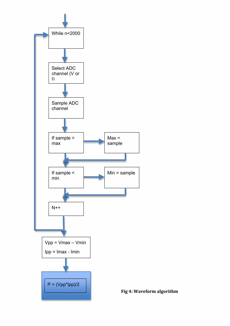
A better approach would be to write only the current sample of each sine wave to memory. In order to determine the RMS value of the input voltage or current sine wave, it is necessary to capture the peak value of each sine wave cycle. This could be achieved by comparing the previous sampled value to the current sampled value and determining the maximum value when the current sampled value starts to decrease (i.e. after 90° on a sine wave). This maximum value could then be reset for the next cycle to measure a new voltage or current value. This approach is shown below:
Select ADC channel (V or I)
While n<2000
Sample ADC channel
If sample > max
If sample < min
N++
Vpp = Vmax – Vmin
Ipp = Imax - Imin
Max = sample
Min = sample
P = (Vpp*Ipp)/2 Fig 4: Waveform algorithm
Microprocessor The Design Document specified the Atmel AVRmega8 as a suitable microprocessor for the Smart Meter. It contains 8kb of flash memory and 1kb of SRAM, which is sufficient for the performance requirements of this project but not enough to contain a fully‐featured Smart Meter software package with a complete ZigBee stack and improved power consumption measurement and analysis. A fully accredited ZigBee stack takes up approximately 40kb.
The mega8 also features a 6 channel, 10 bit ADC which was described in the previous section. As it is only necessary to measure the current and voltage of the test circuit and no other parameters, two ADC channels are sufficient for this project.
A key benefit of this microprocessor is its on‐board SPI and USART support. Both these protocols are used to communicate with the microprocessor – SPI between the mega8 and the ISP programmer or the RF230 radio chip, and USART between the mega8 and a computer and user interface.
The microprocessor also provides 23 IO pins. Whilst some of these have been utilised for the ADC channels, SPI bus, USART link and external interrupts, there still remain approximately 10 IO pins which is more than enough for test/debugging purposes.
Wireless link The Atmel AT86RF230 chip has been chosen to provide the wireless functionality for the Smart Metering System. It operates on a low power, 1.8v‐3.3v supply. It uses SPI bus as a communications interface which makes it ideal for pairing with the Atmel mega8 microprocessor. As described later on, the RF230 chip uses the IEEE 802.15.4 Wireless Personal Area Network standard for data transmission in the 2.4Ghz band. It provides full physical and data link layer functionality, meaning that the project can be built on top of an already existing wireless platform.
Computer link RS232 presents the most common method of interface with a personal computer. It is well‐developed and many libraries are available for COM port access in Windows. In terms of transmission, the AVRmega8 supports a USART (synchronous/asynchronous serial) interface which can be configured to transmit and receive data based on the RS232 protocol. RS232 avoids some of the problems associated with implementing USB, including complexity and lack of widely‐available and user‐friendly interface libraries.
As the mega8 only operates at a 5v logic level, it is necessary to use a MAX232 voltage level converter in order to interface correctly with a computer’s RS‐232 connection.
The USART data can be received on the computer through a COM port, configured using either a Terminal application, open source Win32 COM

program such as Thierry Scheider’s, or Matlab’s in‐built serial link functionality. See the User Interface section for more details.
Network stack implementation
Packet encapsulation Given that multiple Smart Meters will be operating simultaneously for the majority of applications, it is necessary to consider the data transmission protocols which will enable all meters to share the wireless access medium and route messages to the network co‐ordinator. The performance requirements outlined in the Requirements Analysis stated that:
“The Smart Meter shall be able to transmit data wirelessly to a computer using the ZigBee open standard networking protocol.”
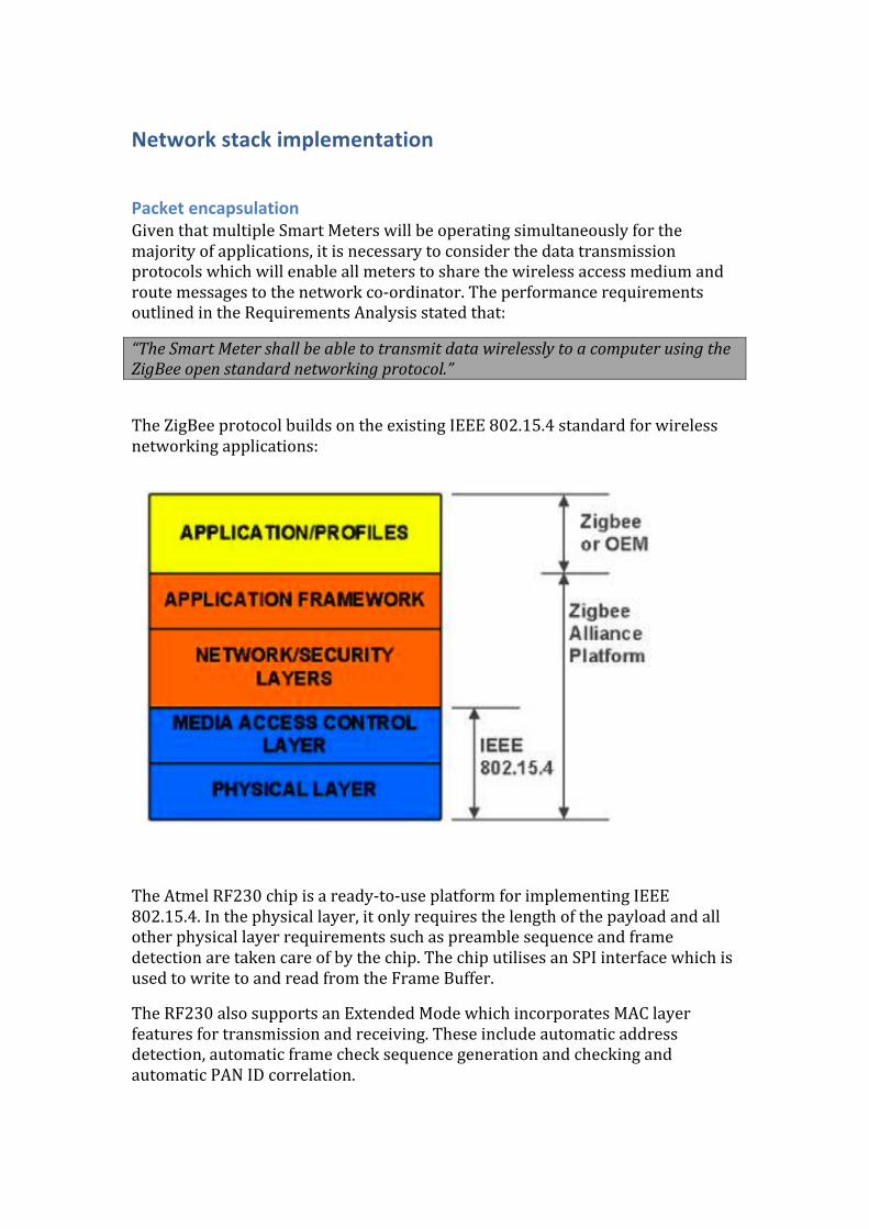
The ZigBee protocol builds on the existing IEEE 802.15.4 standard for wireless networking applications:
The Atmel RF230 chip is a ready‐to‐use platform for implementing IEEE 802.15.4. In the physical layer, it only requires the length of the payload and all other physical layer requirements such as preamble sequence and frame detection are taken care of by the chip. The chip utilises an SPI interface which is used to write to and read from the Frame Buffer.
The RF230 also supports an Extended Mode which incorporates MAC layer features for transmission and receiving. These include automatic address detection, automatic frame check sequence generation and checking and automatic PAN ID correlation.
The ZigBee network layer adds on another layer of functionality onto the IEEE 802.15.4 protocol. Whereas the latter only provides for data transfer between nodes in a PAN and a single PAN co‐ordinator, ZigBee specifies a means of generating mesh networks which route data between PAN co‐ordinators in the same network. Additionally, ZigBee networks are self‐healing and achieve optimum link quality based on data quality link indicators.
Implementation of network protocols It is not feasible to implement the complete network stack according to specification for a number of reasons. Both the IEEE 802.15.4 and ZigBee standards have many functions which are outside the scope of this project. Additionally, the complete network stack would take up around 40KB which is larger than the memory in the specified microprocessor (AVRmega8). In order to demonstrate some of the useful aspects of the network stack whilst retaining a balance between this aspect of the project and other parts, it has been necessary to implement a reduced network stack with some key functionality demonstrated.
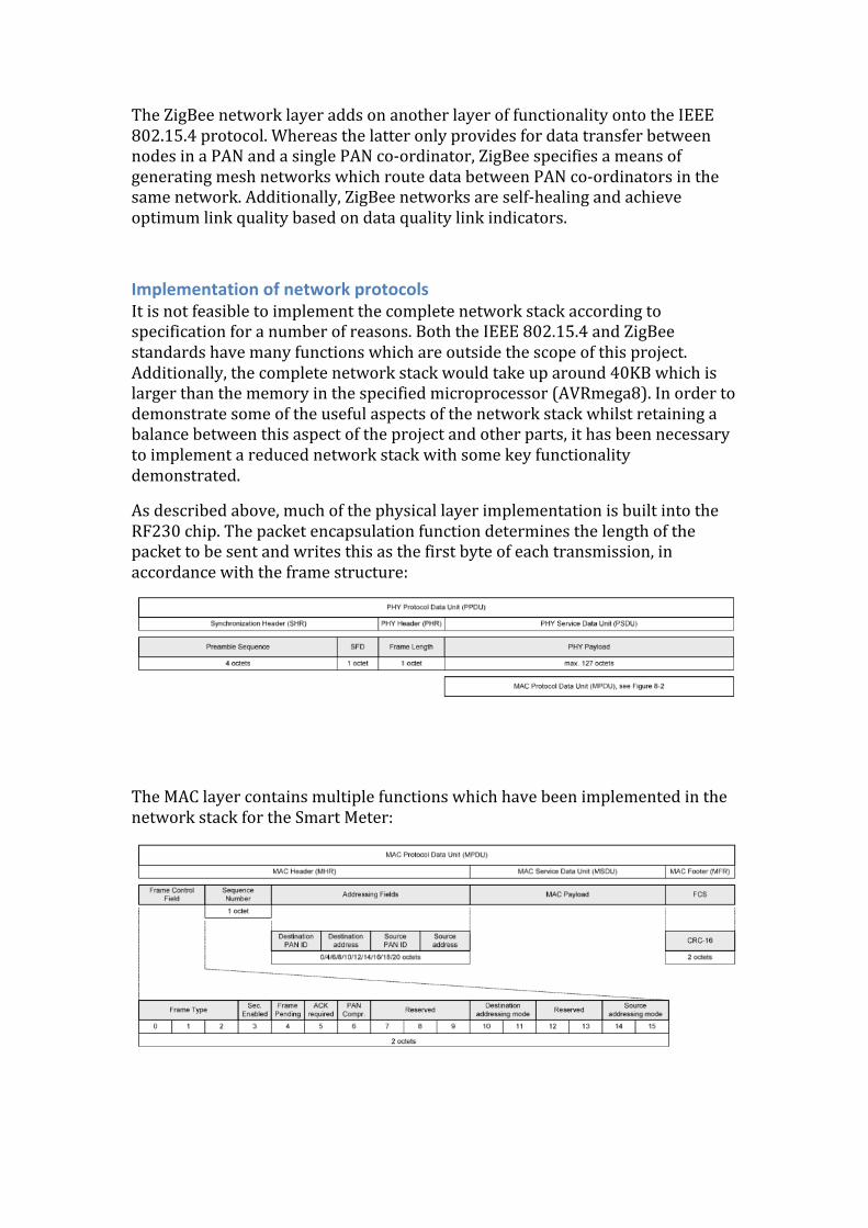
As described above, much of the physical layer implementation is built into the RF230 chip. The packet encapsulation function determines the length of the packet to be sent and writes this as the first byte of each transmission, in accordance with the frame structure:
The MAC layer contains multiple functions which have been implemented in the network stack for the Smart Meter:
Frame type – A packet sent by either TX or RX node can be either a Beacon (type 0), a Data packet (type 1) or a Command (type 3). Commands which are implemented for this network stack include association request, association response and network discovery. Acknowledgement – The Extended Mode of the RF230 chip supports automatic transmission and reception of acknowledgement packets. In order to implement this in the stack, some parameters must be specified:
‐ Maximum number of frame retries ‐ Maximum number of CSMA retries ‐ CSMA seed and backoff exponent
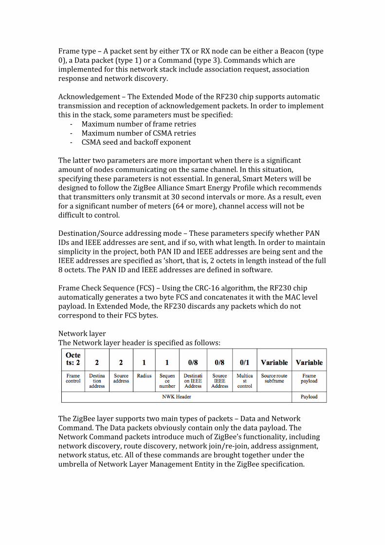
The latter two parameters are more important when there is a significant amount of nodes communicating on the same channel. In this situation, specifying these parameters is not essential. In general, Smart Meters will be designed to follow the ZigBee Alliance Smart Energy Profile which recommends that transmitters only transmit at 30 second intervals or more. As a result, even for a significant number of meters (64 or more), channel access will not be difficult to control. Destination/Source addressing mode – These parameters specify whether PAN IDs and IEEE addresses are sent, and if so, with what length. In order to maintain simplicity in the project, both PAN ID and IEEE addresses are being sent and the IEEE addresses are specified as ‘short, that is, 2 octets in length instead of the full 8 octets. The PAN ID and IEEE addresses are defined in software. Frame Check Sequence (FCS) – Using the CRC‐16 algorithm, the RF230 chip automatically generates a two byte FCS and concatenates it with the MAC level payload. In Extended Mode, the RF230 discards any packets which do not correspond to their FCS bytes. Network layer The Network layer header is specified as follows:
The ZigBee layer supports two main types of packets – Data and Network Command. The Data packets obviously contain only the data payload. The Network Command packets introduce much of ZigBee’s functionality, including network discovery, route discovery, network join/re‐join, address assignment, network status, etc. All of these commands are brought together under the umbrella of Network Layer Management Entity in the ZigBee specification.
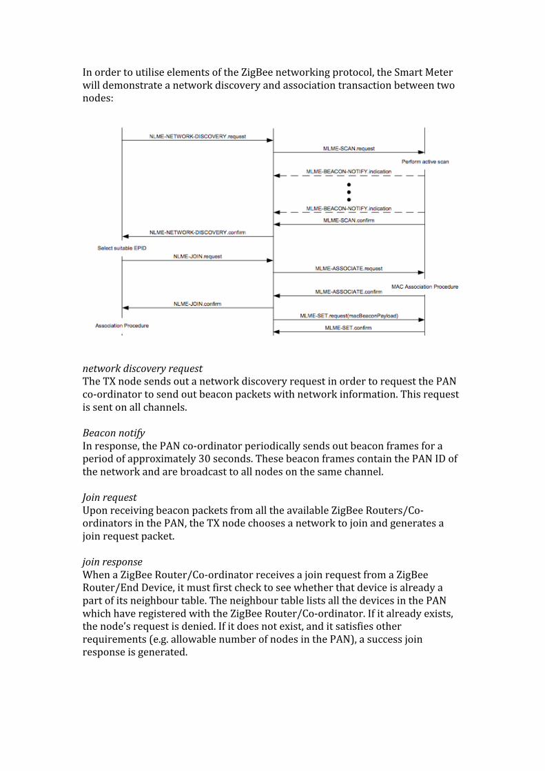
In order to utilise elements of the ZigBee networking protocol, the Smart Meter will demonstrate a network discovery and association transaction between two nodes:
network discovery request The TX node sends out a network discovery request in order to request the PAN co‐ordinator to send out beacon packets with network information. This request is sent on all channels. Beacon notify In response, the PAN co‐ordinator periodically sends out beacon frames for a period of approximately 30 seconds. These beacon frames contain the PAN ID of the network and are broadcast to all nodes on the same channel. Join request Upon receiving beacon packets from all the available ZigBee Routers/Co‐ordinators in the PAN, the TX node chooses a network to join and generates a join request packet. join response When a ZigBee Router/Co‐ordinator receives a join request from a ZigBee Router/End Device, it must first check to see whether that device is already a part of its neighbour table. The neighbour table lists all the devices in the PAN which have registered with the ZigBee Router/Co‐ordinator. If it already exists, the node’s request is denied. If it does not exist, and it satisfies other requirements (e.g. allowable number of nodes in the PAN), a success join response is generated.
Software
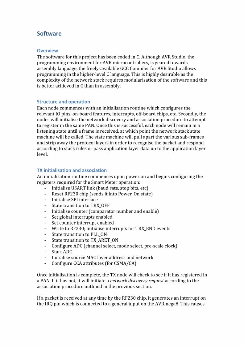
Overview The software for this project has been coded in C. Although AVR Studio, the programming environment for AVR microcontrollers, is geared towards assembly language, the freely‐available GCC Compiler for AVR Studio allows programming in the higher‐level C language. This is highly desirable as the complexity of the network stack requires modularisation of the software and this is better achieved in C than in assembly.
Structure and operation Each node commences with an initialisation routine which configures the relevant IO pins, on‐board features, interrupts, off‐board chips, etc. Secondly, the nodes will initialise the network discovery and association procedure to attempt to register in the same PAN. Once this is successful, each node will remain in a listening state until a frame is received, at which point the network stack state machine will be called. The state machine will pull apart the various sub‐frames and strip away the protocol layers in order to recognise the packet and respond according to stack rules or pass application layer data up to the application layer level.
TX initialisation and association An initialisation routine commences upon power on and begins configuring the registers required for the Smart Meter operation:
‐ Initialise USART link (baud rate, stop bits, etc) ‐ Reset RF230 chip (sends it into Power_On state) ‐ Initialise SPI interface ‐ State transition to TRX_OFF ‐ Initialise counter (comparator number and enable) ‐ Set global interrupts enabled ‐ Set counter interrupt enabled ‐ Write to RF230; initialise interrupts for TRX_END events ‐ State transition to PLL_ON ‐ State transition to TX_ARET_ON ‐ Configure ADC (channel select, mode select, pre‐scale clock) ‐ Start ADC ‐ Initialise source MAC layer address and network ‐ Configure CCA attributes (for CSMA/CA)
Once initialisation is complete, the TX node will check to see if it has registered in a PAN. If it has not, it will initiate a network discovery request according to the association procedure outlined in the previous section. If a packet is received at any time by the RF230 chip, it generates an interrupt on the IRQ pin which is connected to a general input on the AVRmega8. This causes

an interrupt on the mega8 and the program executes the RF230 interrupt service routine to determine the cause of the interrupt. The ISR reads the IRQ_STATUS register of the RF230 chip to determine the cause of the interrupt. If IRQ_STATUS = 0x08, the interrupt represents the end of a frame transmission or reception and the program proceeds to commence the network stack state machine in order to decode the packet. In the event that no packets are received following the network discovery request, the TX node will generate an error which will illuminate the red status LED on the circuit board. In the complete network stack, this would be accompanied by a back‐off period before further retries are enabled. However, this function is not present in this Smart Meter. The state machine looks at the Frame Type bits of the MAC Frame Control Header to determine whether the packet is a Beacon, a Data packet or a Command. If the Frame Type bits are invalid, the state machine will return an error. However, this functionality is built into the Extended Mode of the mega8 chip. The state machine will then accordingly read off the parameters in the MAC Header such as Source PAN ID and Source IEEE Address. If the packet is a Beacon, the stack will check to see if the node is a member of that PAN yet. If not, the stack will initiate the network join request. If the packet is a Command, the stack will look at the command type bit fields to determine what MAC layer command is being received. If it is a join response, the request can either be successful or unsuccessful and the PAN ID of the PAN Co‐ordinator will be added to the node’s neighbour table in the former case.
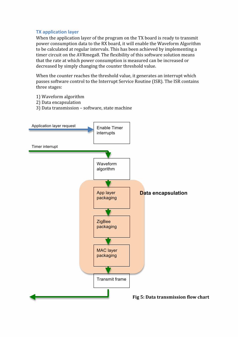
TX application layer When the application layer of the program on the TX board is ready to transmit power consumption data to the RX board, it will enable the Waveform Algorithm to be calculated at regular intervals. This has been achieved by implementing a timer circuit on the AVRmega8. The flexibility of this software solution means that the rate at which power consumption is measured can be increased or decreased by simply changing the counter threshold value.
When the counter reaches the threshold value, it generates an interrupt which passes software control to the Interrupt Service Routine (ISR). The ISR contains three stages:
1) Waveform algorithm 2) Data encapsulation 3) Data transmission – software, state machine
Enable Timer interrupts
Waveform algorithm
App layer packaging
ZigBee packaging
MAC layer packaging
Transmit frame
Application layer request
Timer interrupt
Data encapsulation
Fig 5: Data transmission flow chart
RX initialisation and association The RX node has a very similar software structure to that of the TX node. After the initialisation function has been completed, the node changes into the RX_AACK state to wait for any incoming packets.
The node waits until it receives a network discovery request from any available TX nodes. If it does, it initiates the beacon notify function which sends out a MAC layer Beacon approximately every second for a predetermined amount of time or until a network join request is received.
If a network join request is received, the stack checks to see if the request is from a node which is already a member of the neighbour table. If it is, the request is denied. If it is not, the request is successful and a network join response is transmitted to the TX node.
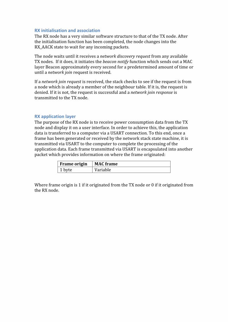
RX application layer The purpose of the RX node is to receive power consumption data from the TX node and display it on a user interface. In order to achieve this, the application data is transferred to a computer via a USART connection. To this end, once a frame has been generated or received by the network stack state machine, it is transmitted via USART to the computer to complete the processing of the application data. Each frame transmitted via USART is encapsulated into another packet which provides information on where the frame originated:
Frame origin MAC frame 1 byte Variable
Where frame origin is 1 if it originated from the TX node or 0 if it originated from the RX node.
Physical specifications The Smart Metering System comprises the following components:
‐ 1 x TX board ‐ 1 x Voltage/Current measurement board ‐ 1 x RX board ‐ 1 x RS232 – USB converter ‐ 1 x Power consumption test rig
Maximum ratings Vcc for the AVR mega8 = 5v Vcc for the AVR RF230 is 1.8v < v < 3.6v Max measurable current = 10A Max measurable voltage = 20V rms
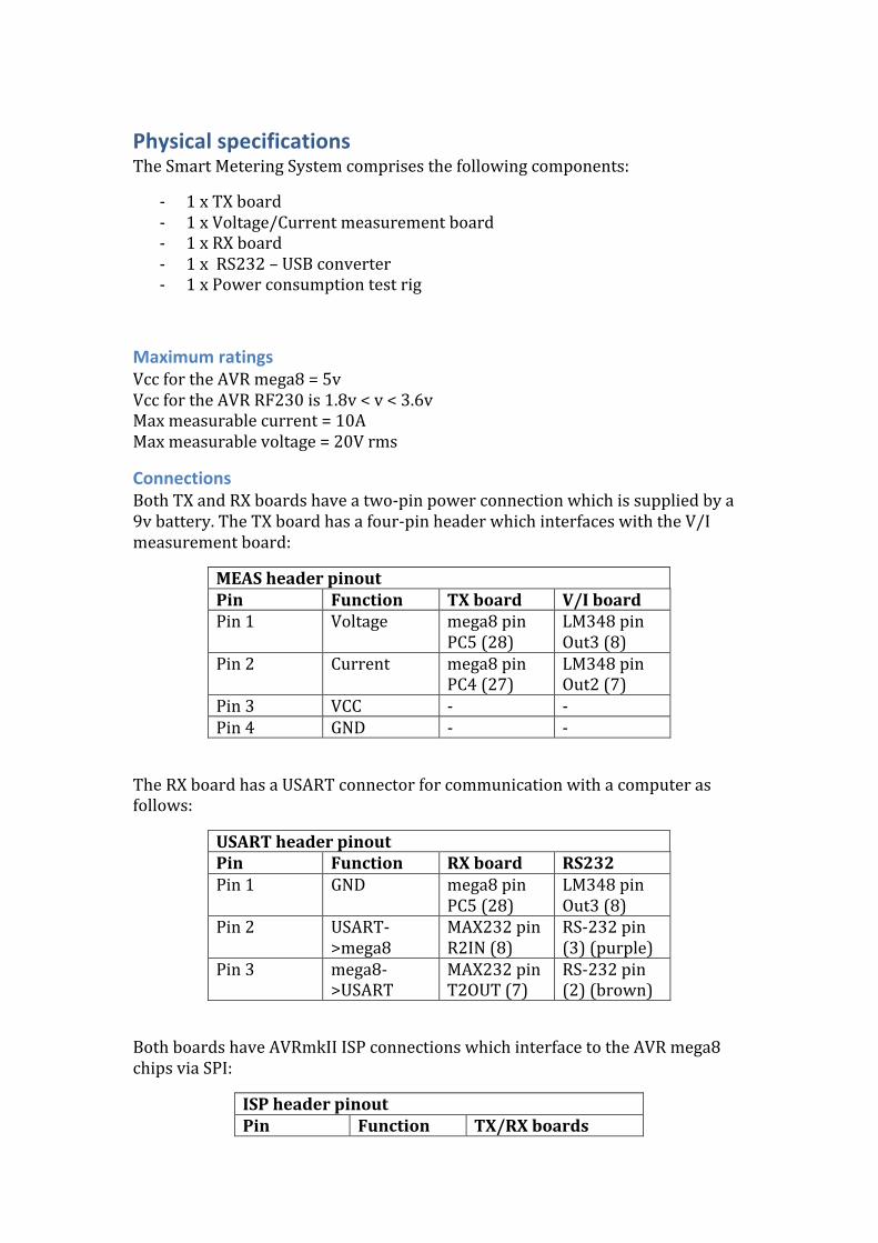
Connections Both TX and RX boards have a two‐pin power connection which is supplied by a 9v battery. The TX board has a four‐pin header which interfaces with the V/I measurement board:
MEAS header pinout Pin Function TX board V/I board Pin 1 Voltage mega8 pin
PC5 (28) LM348 pin Out3 (8)
Pin 2 Current mega8 pin PC4 (27)
LM348 pin Out2 (7)
Pin 3 VCC ‐ ‐ Pin 4 GND ‐ ‐
The RX board has a USART connector for communication with a computer as follows:
USART header pinout Pin Function RX board RS232 Pin 1 GND mega8 pin
PC5 (28) LM348 pin Out3 (8)
Pin 2 USART‐>mega8
MAX232 pin R2IN (8)
RS‐232 pin (3) (purple)
Pin 3 mega8‐>USART
MAX232 pin T2OUT (7)
RS‐232 pin (2) (brown)
Both boards have AVRmkII ISP connections which interface to the AVR mega8 chips via SPI:
ISP header pinout Pin Function TX/RX boards
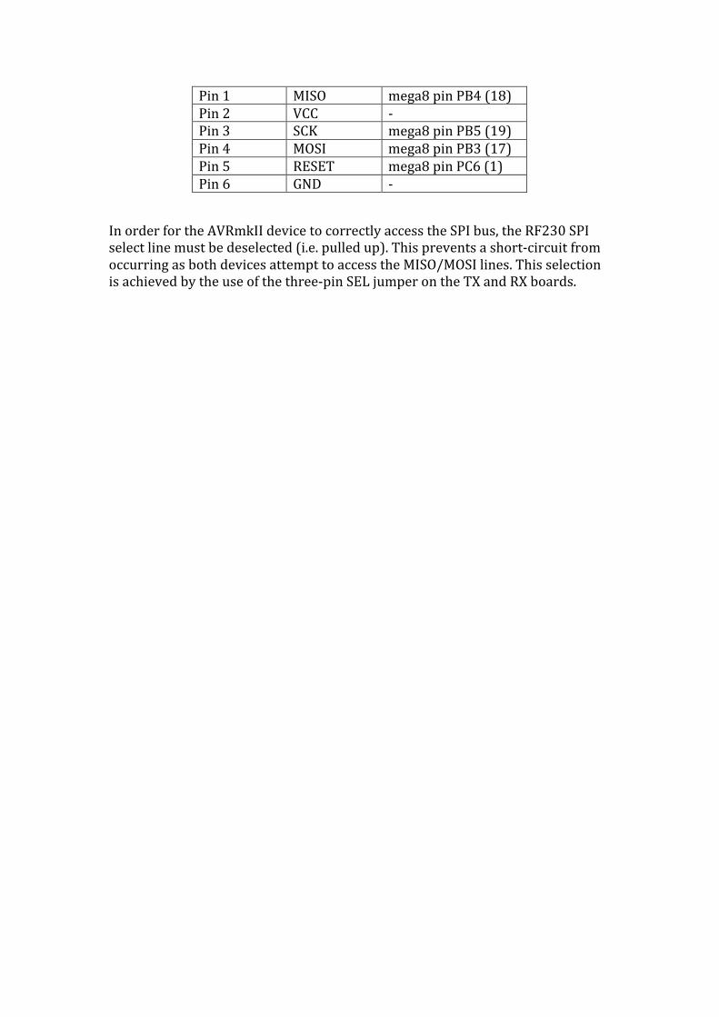
Pin 1 MISO mega8 pin PB4 (18) Pin 2 VCC ‐ Pin 3 SCK mega8 pin PB5 (19) Pin 4 MOSI mega8 pin PB3 (17) Pin 5 RESET mega8 pin PC6 (1) Pin 6 GND ‐
In order for the AVRmkII device to correctly access the SPI bus, the RF230 SPI select line must be deselected (i.e. pulled up). This prevents a short‐circuit from occurring as both devices attempt to access the MISO/MOSI lines. This selection is achieved by the use of the three‐pin SEL jumper on the TX and RX boards.
Testing methodology / Test points
Hardware 1. LED output array on AVRmega8 TX module
In order to remove any problems associated with the telecommunications interface between the transmitter and receiver modules, a LED output array will be implemented on the outputs of the AVRmega8 transmitter‐side module. This will allow testing of the ADC functionality and software for voltage and current calculation.
While this test point was present for the Smart Meter prototype in May, it was not incorporated into the final design of the Smart Meter. However, with many spare IO pins on the mega8, it is quite feasible to attach a 8‐10 wide LED strip to display power consumption at the TX board.
2. SPI MOSI pin on AVRmega8 TX and RX modules Using a CRO to investigate the output of the SPI MOSI pin will enable testing of the SPI interface with the AT86RF230 TX and RX chips.
3. LED output array on AVRmega8 RX module By outputting the received ZigBee data onto a LED array on the AVRmega8 RX chip, it can be determined whether this data agrees with the corresponding test point on the TX chip. This will validate the success of the ZigBee telecommunications link.
While this is feasible, the utility of the USART link between the RX board and a computer meant that this test point was not as useful as once thought. It was felt that the chance of a data error between the RX board and the computer was very small and that such an error could easily be discovered and debugged through the use of the USART link. As a result, it was decided that the effort of incorporating this test point into the design outweighed its usefulness.
4. RS232 TX pin Using a CRO to investigate whether there is any activity on this pin will determine whether the RS232 interface is operating correctly.
5. Analog inputs to AVRmega8 TX module By using a multimeter to measure these inputs, the correct functioning of the transformers and op‐amps can be established.
Software 1. Data log of ADC output on AVRmega8 TX module
In order to troubleshoot problems in the analog circuitry (i.e. current and voltage transformers and op‐amps), a log of the ADC output will allow scrutiny of the input data before it enters any telecommunications stage or serial interface.
Validating the data at this stage will prevent any false diagnoses of other problems in later functional blocks.
2. Data log of calculated voltage and current values on AVRmega8 TX module
If the calculation algorithm is not determining the correct RMS voltage and current values, this log will allow closer inspection of potential errors in the calculation code. This also ensures that data integrity is maintained up until the first serial interface in the system.
3. Data log on SPI MOSI outputs on AVRmega8 TX module To ensure that the SPI interface on the transmit module is functioning correctly, the data can be written into a data log. This will allow detailed analysis of the packets in order to troubleshoot any problems between the AVRmega8 chip and the AT86RF230 chip.
4. Data log on SPI MISO input of AVRmega8 RX module This test point will enable a comparison between itself and test point 3 to ensure that the ZigBee data packets have been transmitted successfully.
5. Data log on USART serial output of AVRmega8 RX module Logging the data stream coming from the USART output of the AVRmega8 RX chip will enable closer inspection of the received ZigBee data before it is sent via the RS232 interface to the computer.
6. Data log of RS232 received data on computer Before any processing or displaying of the received data occurs, an RS232 'dump' will enable the final communications stage of the system to be validated.

User interface There were a number of possible alternatives development environments for the user interface. A Win32 program was initially chosen as the vehicle for the user interface due to its flexibility and compatibility.
However, as time progressed, it became clear that the Win32 development environment was anything but clear. A lack of easy‐to‐use technical support websites, high levels of complexity and an unfamiliarity with the programming involved meant that this idea was scrapped.
Instead, the Matlab environment was considered as a tool for creating a Smart Meter GUI. It offered support for COM port objects as well as easy‐to‐use tools and functions for creating a multitude of graphs. It has an in‐built GUI Development Environment which had useful tutorials to help with understanding. Additionally, Matlab was a familiar environment and the programming language was already known. As a result, Matlab was chosen as the development program for the Smart Meter User Interface.
The Design Document specified numerous functionalities which the user interface of the Smart Meter must exhibit:
“The user interface shall be able to display the current power consumption of the circuit being measured.” The GUI continually reads the serial port object and waits until either a data byte arrives or a timeout occurs. This ensures that packets which are sent to the RX board are almost immediately read into the GUI.
“The user interface shall be able to continuously update as data arrives without any user interaction.” As the Smart Metering System is intended to be an intelligent, self‐healing network (as per the ZigBee protocol), it was intended that user interaction be kept to a minimum so as to demonstrate the independence and ‘smart’ aspect of the system. As a result, the interface provides all the necessary data without any user interaction apart from the initial ‘Start’ button which opens the COM port and begins processing the received packets.
“The user interface shall be able to display a history of power consumption for the circuit being measured.” In order to enhance the user‐friendliness of the GUI, a graph was inserted which displays the power consumption of the circuit for the last 18 readings (i.e. approx 18 seconds). This provides a clean and eye‐catching method for displaying the essence of the Smart Metering System. It also allows for increased functionality as more nodes are added to the system and more graphs can be added to the GUI.

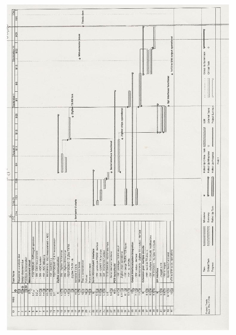
Project timeline
Discussion

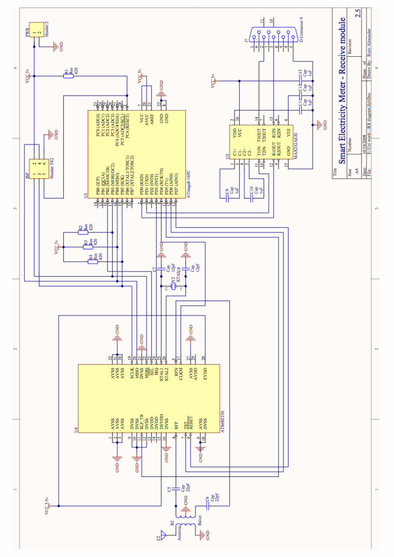
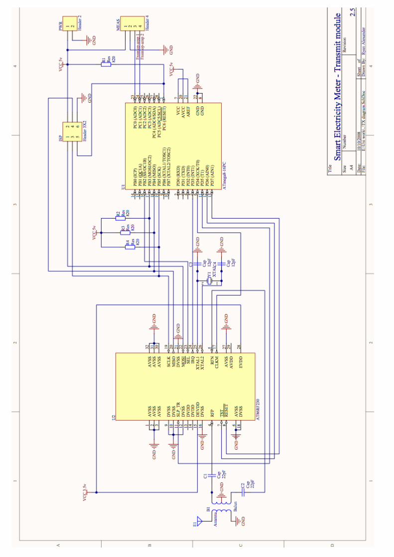
Appendix A: Microcontroller schematics
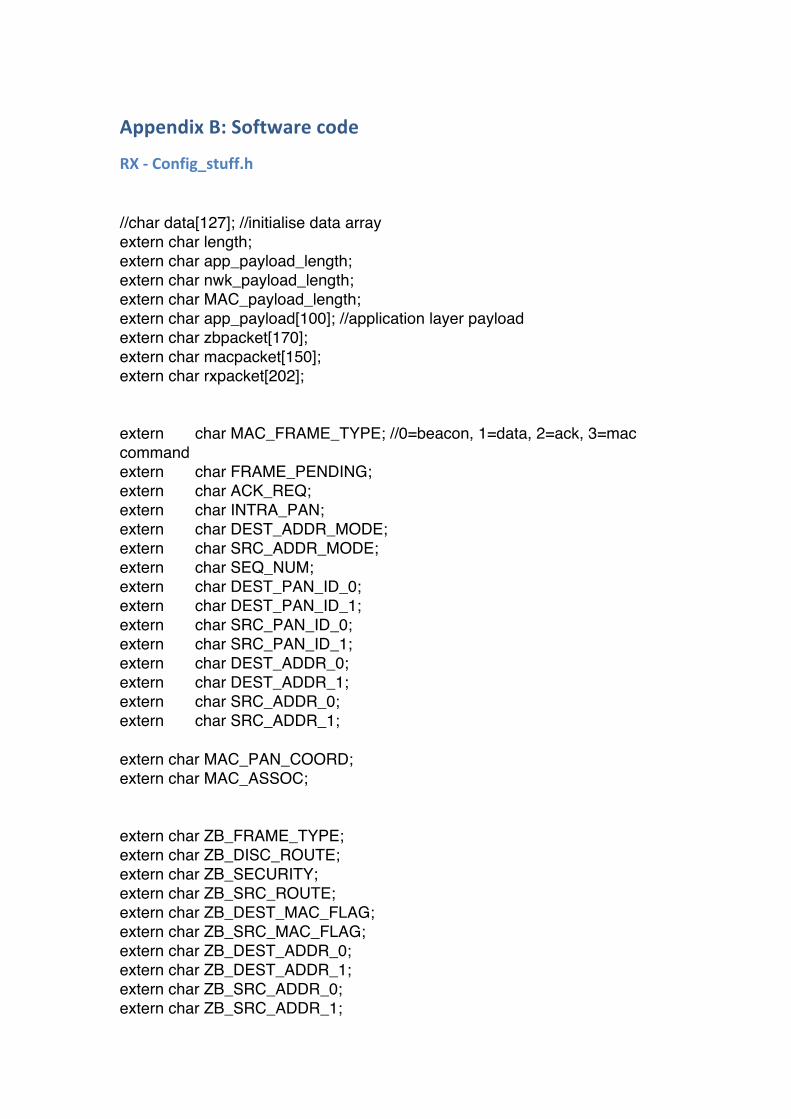
Appendix B: Software code
RX ‐ Config_stuff.h //char data[127]; //initialise data array extern char length; extern char app_payload_length; extern char nwk_payload_length; extern char MAC_payload_length; extern char app_payload[100]; //application layer payload extern char zbpacket[170]; extern char macpacket[150]; extern char rxpacket[202]; extern char MAC_FRAME_TYPE; //0=beacon, 1=data, 2=ack, 3=mac command extern char FRAME_PENDING; extern char ACK_REQ; extern char INTRA_PAN; extern char DEST_ADDR_MODE; extern char SRC_ADDR_MODE; extern char SEQ_NUM; extern char DEST_PAN_ID_0; extern char DEST_PAN_ID_1; extern char SRC_PAN_ID_0; extern char SRC_PAN_ID_1; extern char DEST_ADDR_0; extern char DEST_ADDR_1; extern char SRC_ADDR_0; extern char SRC_ADDR_1; extern char MAC_PAN_COORD; extern char MAC_ASSOC; extern char ZB_FRAME_TYPE; extern char ZB_DISC_ROUTE; extern char ZB_SECURITY; extern char ZB_SRC_ROUTE; extern char ZB_DEST_MAC_FLAG; extern char ZB_SRC_MAC_FLAG; extern char ZB_DEST_ADDR_0; extern char ZB_DEST_ADDR_1; extern char ZB_SRC_ADDR_0; extern char ZB_SRC_ADDR_1;
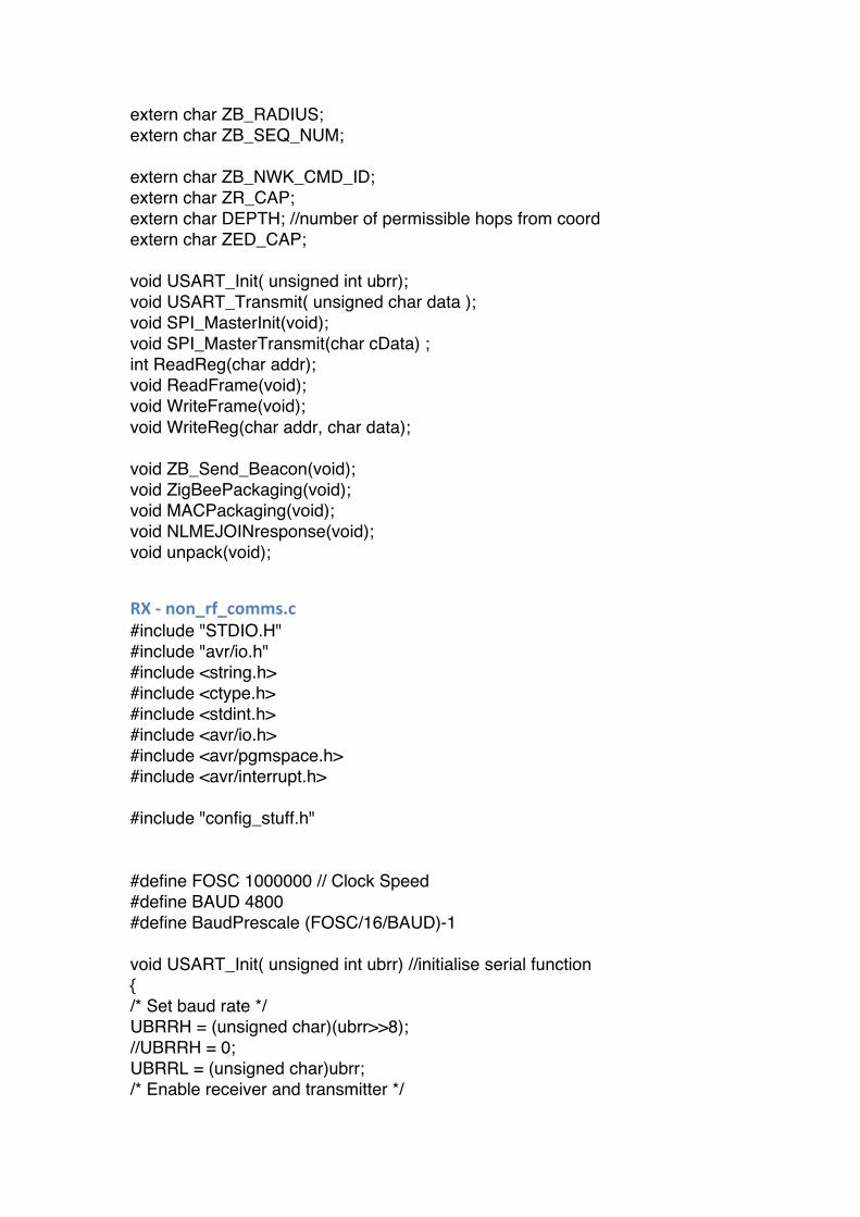
extern char ZB_RADIUS; extern char ZB_SEQ_NUM; extern char ZB_NWK_CMD_ID; extern char ZR_CAP; extern char DEPTH; //number of permissible hops from coord extern char ZED_CAP; void USART_Init( unsigned int ubrr); void USART_Transmit( unsigned char data ); void SPI_MasterInit(void); void SPI_MasterTransmit(char cData) ; int ReadReg(char addr); void ReadFrame(void); void WriteFrame(void); void WriteReg(char addr, char data); void ZB_Send_Beacon(void); void ZigBeePackaging(void); void MACPackaging(void); void NLMEJOINresponse(void); void unpack(void);
RX ‐ non_rf_comms.c #include "STDIO.H" #include "avr/io.h" #include <string.h> #include <ctype.h> #include <stdint.h> #include <avr/io.h> #include <avr/pgmspace.h> #include <avr/interrupt.h> #include "config_stuff.h" #define FOSC 1000000 // Clock Speed #define BAUD 4800 #define BaudPrescale (FOSC/16/BAUD)-1 void USART_Init( unsigned int ubrr) //initialise serial function { /* Set baud rate */ UBRRH = (unsigned char)(ubrr>>8); //UBRRH = 0; UBRRL = (unsigned char)ubrr; /* Enable receiver and transmitter */
UCSRB = (1<<RXEN)|(1<<TXEN); /* Set frame format: 1stop bit, 8bit size */ UCSRC = (1<<URSEL)|(0<<USBS)|(3<<UCSZ0); } void USART_Transmit( unsigned char data ) //serial transmit function { /* Wait for empty transmit buffer */ while ( !( UCSRA & (1<<UDRE)) ) ; /* Put data into buffer, sends the data */ UDR = data; } void SPI_MasterInit(void) { /* Set MOSI and SCK output, and SS output */ DDRB = (1<<DDB2)|(1<<DDB3)|(1<<DDB5); DDRD = (1<<DDB5)|DDRD; //sets SLP_TR as output PORTD = (0<<5)|PORTD; //and low /* Enable SPI, Master, set clock rate fck/16 */ SPCR = (1<<SPE)|(1<<MSTR)|(1<<SPR0); } void SPI_MasterTransmit(char cData) { /* Start transmission */ SPDR = cData; /* Wait for transmission complete */ while(!(SPSR & (1<<SPIF))); //looks at SPI interrupt flag in SPSR register } int ReadReg(char addr) { PORTB = (0<<2); //pull SS line low char SPIdata = (1<<7)|addr; // -127 //read reg SPI_MasterTransmit(SPIdata); //transmit read reg command SPI_MasterTransmit(0); //transmit read reg command x2 ie 'stuffing' byte PORTB = (1<<2); //pull SS line high char output = SPDR; //receive data into SPIdata return output; } void ReadFrame(void) { //USART_Transmit(5); int i = 0; //counter
PORTB = (0<<2); //pull SS line low char SPIdata = (1<<5); // read frame SPI_MasterTransmit(SPIdata); //transmit read reg command SPI_MasterTransmit(0); //transmit read reg command x2 ie 'stuffing' byte length = SPDR; //receive packet header (i.e. frame length) for (i=0;i<length;i++) { SPI_MasterTransmit(0); rxpacket[i] = SPDR; } SPI_MasterTransmit(0); char lqi = SPDR; //link quality byte PORTB = (1<<2); //pull SS line high //return output; } void WriteFrame(void) { char SPIdatatemp = ReadReg(0x01); WriteReg(2, 0x08); /*reset state machine*/ if (SPIdatatemp == 0) WriteReg(2, 0x08); /*---------------------*/ while (SPIdatatemp == 31) { SPIdatatemp = ReadReg(0x01); } WriteReg(2, 0x09); while (SPIdatatemp == 31) { SPIdatatemp = ReadReg(0x01); } WriteReg(2, 0x19); //go to TX_ARET state while (SPIdatatemp == 31) { SPIdatatemp = ReadReg(0x01); } //--------------sending data via SPI to RF230--------------------// int i=0; PORTB = (0<<2); //pull SS line low
char SPIdata = (3<<5); // write frame command SPI_MasterTransmit(SPIdata); //transmit write frame command SPI_MasterTransmit(MAC_payload_length); //transmit PHR (length) USART_Transmit(MAC_payload_length-2); for (i=0;i<(MAC_payload_length-2);i++) { //don't need to SPI push FCS bytes SPI_MasterTransmit(macpacket[i]); USART_Transmit(macpacket[i]); } PORTB = (1<<2); //pull SS line high /*TX start*/ WriteReg(0x02, 0x02); //write TX_START to TRX_STATE register //---------------------------------------------------------------// while (SPIdatatemp == 0x12) //wait for busy TX to end { SPIdatatemp = ReadReg(0x01); } WriteReg(2, 0x09); while (SPIdatatemp == 31) //wait for state transition to end { SPIdatatemp = ReadReg(0x01); } //WriteReg(2, 0x16); //go to RX_AACK_ON state WriteReg(2, 0x6); //go to RX_AACK_ON state while (SPIdatatemp == 31) { SPIdatatemp = ReadReg(0x01); } } void WriteReg(char addr, char data) { PORTB = (0<<2); //pull SS line low char SPIaddr = (3<<6)|addr; // reg write SPI_MasterTransmit(SPIaddr); //transmit read reg command SPI_MasterTransmit(data); //transmit read reg command x2 ie 'stuffing' byte PORTB = (1<<2); //pull SS line high }
RX ‐ RX.c #include "STDIO.H" #include "avr/io.h" #include <string.h>
#include <ctype.h> #include <stdint.h> #include <avr/io.h> #include <avr/pgmspace.h> #include <avr/interrupt.h> #include "config_stuff.h" #define FOSC 1000000 // Clock Speed #define BAUD 4800 #define BaudPrescale (FOSC/16/BAUD)-1 /*initialise packets*/ char length=0; char app_payload_length = 0; char nwk_payload_length = 0; char MAC_payload_length = 0; char rxpacket[202]; //data array char app_payload[100]; //application layer payload char zbpacket[170]; char macpacket[150]; /*ZigBee frame*/ char ZB_FRAME_TYPE; char ZB_DISC_ROUTE; char ZB_SECURITY; char ZB_SRC_ROUTE; char ZB_DEST_MAC_FLAG; char ZB_SRC_MAC_FLAG; char ZB_DEST_ADDR_0; char ZB_DEST_ADDR_1; char ZB_SRC_ADDR_0; char ZB_SRC_ADDR_1; char ZB_RADIUS; char ZB_SEQ_NUM; char ZB_NWK_CMD_ID; char ZR_CAP = 1; char DEPTH = 4; //number of permissible hops from coord char ZED_CAP = 1; /*MAC frame*/ char MAC_FRAME_TYPE = 1; //0=beacon, 1=data, 2=ack, 3=mac command char FRAME_PENDING = 0; char ACK_REQ = 0; char INTRA_PAN = 0; char DEST_ADDR_MODE = 2; char SRC_ADDR_MODE = 2;

char SEQ_NUM = 0; char DEST_PAN_ID_0 = 1; char DEST_PAN_ID_1 = 0; char SRC_PAN_ID_0 = 1; char SRC_PAN_ID_1 = 0; char DEST_ADDR_0 = 8; char DEST_ADDR_1 = 0; char SRC_ADDR_0 = 7; char SRC_ADDR_1 = 0; char MAC_PAN_COORD = 1; char MAC_ASSOC = 1; struct { char mac_addr[8]; char net_addr[2]; char device_type[2]; char rx_on_when_idle[1]; char relationship[3]; char tx_failure[5]; char lqi[5]; char out_cost[5]; } neighbour_table; struct { char SRC_PAN_ID_0; char SRC_PAN_ID_1; char app_payload_length; } rxstack; ISR(INT1_vect) { //USART_Transmit(2); //check for int vector char result = ReadReg(0x0F); //read IRQ_STATUS register //char data[127]; //init SPI RX data buffer int i=0; //counter if (result == 8) {//if bit 3 TRX_END is set ReadFrame(); //read frame from SPI USART_Transmit(length); for (i=0;i<length;i++) USART_Transmit(rxpacket[i]); //send frame, byte by byte, to USART unpack(); } } void unpack(void) {
//USART_Transmit(14); if ((rxpacket[0]&3) == 3) //mac command frame { //USART_Transmit(15); rxstack.app_payload_length = length - 11; //for a MAC beacon frame rxstack.SRC_PAN_ID_0 = rxpacket[3]; rxstack.SRC_PAN_ID_1 = rxpacket[4]; if ((rxpacket[11]&1) == 1) //association request { //USART_Transmit(16); neighbour_table.mac_addr[0] = rxstack.SRC_PAN_ID_0; neighbour_table.mac_addr[1] = rxstack.SRC_PAN_ID_1; //USART_Transmit(neighbour_table.mac_addr[0]); NLMEJOINresponse(); MACPackaging(); WriteFrame(); } } } //sending beacon ISR(TIMER1_COMPA_vect) { /**send beacon**/ ZB_Send_Beacon(); MACPackaging(); WriteFrame(); /***************/ } void ZB_Send_Beacon(void) //APPLICATION LAYER REQUEST { MAC_FRAME_TYPE = 0; //beacon app_payload[0] = 0; app_payload[1] = 0; app_payload[2] = (ZR_CAP<<2)|(DEPTH<<3)|(ZED_CAP<<7); app_payload[3] = SRC_PAN_ID_0; //PAN ID (extended) //packet[11] = //No TX offset or nwkUpdateId app_payload_length = 4; } void NLMEJOINresponse(void) { MAC_FRAME_TYPE = 3; //MAC command frame
app_payload[0] = 0x02; //association response app_payload[1] = 0; //short addr - not used app_payload[2] = 0; //short addr = not used app_payload[3] = 0; //association successful app_payload_length = 4; } /*ZigBee stack implementation*/ void ZigBeePackaging(void) { /*NWK HEADER*/ zbpacket[0] = (ZB_FRAME_TYPE)|(ZB_DISC_ROUTE<<6); //no protocol vesion zbpacket[1] = (ZB_SECURITY<<1)|(ZB_SRC_ROUTE<<2)|(ZB_DEST_MAC_FLAG<<3)|(ZB_SRC_MAC_FLAG<<4); //no multicast flag zbpacket[2] = ZB_DEST_ADDR_0; zbpacket[3] = ZB_DEST_ADDR_1; zbpacket[4] = ZB_SRC_ADDR_0; zbpacket[5] = ZB_SRC_ADDR_1; zbpacket[6] = ZB_RADIUS; zbpacket[7] = ZB_SEQ_NUM; // no MAC dest or src addresses yet, no multicast control field // no source route subframe yet /*END NWK HEADER*/ if (ZB_FRAME_TYPE == 0) //data frame { nwk_payload_length = 8 + app_payload_length; int i=0; for (i=0;i<app_payload_length;i++) { zbpacket[8+i] = app_payload[i]; } } if (ZB_FRAME_TYPE == 1) //NWK command frame { zbpacket[8] = ZB_NWK_CMD_ID; //then NWK command payload... } } /* MAC layer*/
void MACPackaging(void) { int i=0; if (MAC_FRAME_TYPE==1 && INTRA_PAN==0 && DEST_ADDR_MODE==2 && SRC_ADDR_MODE==2) { MAC_payload_length = 11 + nwk_payload_length + 2; //MAC header and FCS macpacket[0] = (MAC_FRAME_TYPE)|(FRAME_PENDING<<4)|(ACK_REQ<<5)|(INTRA_PAN<<6); macpacket[1] = (DEST_ADDR_MODE<<2)|(SRC_ADDR_MODE<<6); macpacket[2] = SEQ_NUM; macpacket[3] = SRC_PAN_ID_0; //PAN ID 0 macpacket[4] = SRC_PAN_ID_1; //PAN ID 1 macpacket[5] = SRC_ADDR_0; //SHORT ADDR 0 macpacket[6] = SRC_ADDR_1; //SHORT ADDR 1 macpacket[7] = DEST_PAN_ID_0; macpacket[8] = DEST_PAN_ID_1; macpacket[9] = DEST_ADDR_0; macpacket[10] = DEST_ADDR_1; for (i=0;i<nwk_payload_length;i++) { macpacket[11+i] = zbpacket[i]; } } if (MAC_FRAME_TYPE == 0) //beacon { DEST_ADDR_MODE = 0; SRC_ADDR_MODE = 2; MAC_payload_length = 11 + app_payload_length + 2; //MAC header and FCS macpacket[0] = (MAC_FRAME_TYPE)|(FRAME_PENDING<<4)|(ACK_REQ<<5)|(INTRA_PAN<<6); macpacket[1] = (DEST_ADDR_MODE<<2)|(SRC_ADDR_MODE<<6); macpacket[2] = SEQ_NUM; macpacket[3] = SRC_PAN_ID_0; //PAN ID 0 macpacket[4] = SRC_PAN_ID_1; //PAN ID 1 macpacket[5] = SRC_ADDR_0; //SHORT ADDR 0 macpacket[6] = SRC_ADDR_1; //SHORT ADDR 1 /*end mac header, begin mac sub-layer*/ macpacket[7] = 255; //superframe octet 0 macpacket[8] = (MAC_PAN_COORD<<6)|(MAC_ASSOC<<7); //superframe octet 1
macpacket[9] = 0; // no GTS fields macpacket[10] = 0; // no address list fields for (i=0;i<app_payload_length;i++) { macpacket[11+i] = app_payload[i]; } } if (MAC_FRAME_TYPE == 3) //mac command frame { DEST_ADDR_MODE = 2; SRC_ADDR_MODE = 2; MAC_payload_length = 11 + app_payload_length + 2; //MAC header and FCS macpacket[0] = (MAC_FRAME_TYPE)|(FRAME_PENDING<<4)|(ACK_REQ<<5)|(INTRA_PAN<<6); macpacket[1] = (DEST_ADDR_MODE<<2)|(SRC_ADDR_MODE<<6); macpacket[2] = SEQ_NUM; macpacket[3] = SRC_PAN_ID_0; //PAN ID 0 macpacket[4] = SRC_PAN_ID_1; //PAN ID 1 macpacket[5] = SRC_ADDR_0; //SHORT ADDR 0 macpacket[6] = SRC_ADDR_1; //SHORT ADDR 1 macpacket[7] = DEST_PAN_ID_0; macpacket[8] = DEST_PAN_ID_1; macpacket[9] = DEST_ADDR_0; macpacket[10] = DEST_ADDR_1; for (i=0;i<app_payload_length;i++) { macpacket[11+i] = app_payload[i]; } } //txflag=0; } int main(void) { volatile uint8_t SPIdata; //input to SPI SREG = (1<<7); //set global interrupt enable MCUCR = (3<<2); //set rising edge of INT1 to generate an IRQ GICR = (1<<7); //set INT1 interrupt input enabled DDRD = (1<<DDB7); //set RESET for RF230 as output PORTD = (0<<7); //reset low SPI_MasterInit(); USART_Init (BaudPrescale); //initialise serial
PORTD = (1<<7); //pull reset high /*int i=0; for (i=0;i<20;i++) { USART_Transmit(188); }*/ /*automatic FCS generation*/ WriteReg(0x05,(1<<7)); /* turn on IRQ events for RF230 */ WriteReg(0x0E, (1<<3)); //writes to IRQ_MASK register, enabling TRX_END IRQs WriteReg(2, 0x08); /* initialise source MAC layer address and network */ WriteReg(0x22, SRC_PAN_ID_0); WriteReg(0x23, SRC_PAN_ID_1); WriteReg(0x20, SRC_ADDR_0); WriteReg(0x21, SRC_ADDR_1); WriteReg(2, 0x06); //change state to RX_ON //WriteReg(2, 0x16); //change state to RX_Auto ACK on /*configure counter and interrupt*/ OCR1A = 0x1024;//output compares to this number TCCR1B = 2; //Set CTC and turn on counter and set prescaler to 1/1024 TIMSK = (1<<4); //turns on interrupt mask for counter 1 while(1); }
TX – mac_attributes.h extern char FRAME_TYPE; //0=beacon, 1=data, 2=ack, 3=mac command extern char FRAME_PENDING; extern char ACK_REQ; extern char INTRA_PAN; extern char DEST_ADDR_MODE; extern char SRC_ADDR_MODE; extern char SEQ_NUM; extern char DEST_PAN_ID_0; extern char DEST_PAN_ID_1; extern char SRC_PAN_ID_0; extern char SRC_PAN_ID_1;
extern char DEST_ADDR_0; extern char DEST_ADDR_1; extern char SRC_ADDR_0; extern char SRC_ADDR_1; extern int i; extern char output[127]; //init output from frame buffer extern int txready_flag; extern volatile uint8_t SPIdatatemp; //input to SPI //extern volatile uint16_t n; //counter for adc read extern char input; //input to SPI for TX extern char txflag; //to disable ISR extern int registered; extern volatile uint8_t out[350]; /*initialise packets*/ char length; char app_payload_length; char nwk_payload_length; char MAC_payload_length; char rxpacket[127]; //data array char app_payload[100]; //application layer payload extern char macpacket[100]; extern char zbpacket[80]; void USART_Init( unsigned int ubrr); //initialise serial function void USART_Transmit( unsigned char data ); //serial transmit function void SPI_MasterInit(void); void SPI_MasterTransmit(char cData); int ReadReg(char addr); void WriteReg(char addr, char data); void WriteFrame(void); void WaveformAlgorithm(void); void ZigBeePackaging(void); void MACPackaging(void); void NLMEJOINrequest(void);
TX – non_rf_comms.c #include "STDIO.H" #include "avr/io.h" #include <string.h> #include <ctype.h> #include <stdint.h> #include <avr/io.h> #include <avr/pgmspace.h> #include <avr/interrupt.h>
#include "mac_attributes.h" #define FOSC 1000000 // Clock Speed #define BAUD 4800 #define BaudPrescale (FOSC/16/BAUD)-1 void USART_Init( unsigned int ubrr) //initialise serial function { /* Set baud rate */ UBRRH = (unsigned char)(ubrr>>8); //UBRRH = 0; UBRRL = (unsigned char)ubrr; /* Enable receiver and transmitter */ UCSRB = (1<<RXEN)|(1<<TXEN); /* Set frame format: 1stop bit, 8bit size */ UCSRC = (1<<URSEL)|(0<<USBS)|(3<<UCSZ0); } void USART_Transmit( unsigned char data ) //serial transmit function { /* Wait for empty transmit buffer */ while ( !( UCSRA & (1<<UDRE)) ) ; /* Put data into buffer, sends the data */ UDR = data; } void SPI_MasterInit(void) { /* Set MOSI and SCK output, and SS output */ DDRB = (1<<DDB2)|(1<<DDB3)|(1<<DDB5); DDRD = (1<<DDB5)|DDRD; //sets SLP_TR as output PORTD = (0<<5)|PORTD; //and low /* Enable SPI, Master, set clock rate fck/16 */ SPCR = (1<<SPE)|(1<<MSTR)|(1<<SPR0); } void SPI_MasterTransmit(char cData) { /* Start transmission */ SPDR = cData; /* Wait for transmission complete */ while(!(SPSR & (1<<SPIF))); //looks at SPI interrupt flag in SPSR register } /*RF230 (via SPI)*/ int ReadReg(char addr)
{ PORTB = (0<<2); //pull SS line low char SPIdata = (1<<7)|addr; // -127 //read reg SPI_MasterTransmit(SPIdata); //transmit read reg command SPI_MasterTransmit(0); //transmit read reg command x2 ie 'stuffing' byte PORTB = (1<<2); //pull SS line high char output = SPDR; //receive data into SPIdata return output; } /*RF230 (via SPI)*/ void WriteReg(char addr, char data) { PORTB = (0<<2); //pull SS line low char SPIaddr = (3<<6)|addr; // reg write SPI_MasterTransmit(SPIaddr); //transmit read reg command SPI_MasterTransmit(data); //transmit read reg command x2 ie 'stuffing' byte PORTB = (1<<2); //pull SS line high } void WriteFrame(void) { txflag = 1; char SPIdatatemp = ReadReg(0x01); WriteReg(2, 0x08); /*reset state machine*/ if (SPIdatatemp == 0) WriteReg(2, 0x08); /*---------------------*/ while (SPIdatatemp == 31) { SPIdatatemp = ReadReg(0x01); } WriteReg(2, 0x09); while (SPIdatatemp == 31) { SPIdatatemp = ReadReg(0x01); } WriteReg(2, 0x19); //go to TX_ARET state while (SPIdatatemp == 31) { SPIdatatemp = ReadReg(0x01); }
//--------------sending data via SPI to RF230--------------------// int i=0; PORTB = (0<<2); //pull SS line low char SPIdata = (3<<5); // write frame command SPI_MasterTransmit(SPIdata); //transmit write frame command SPI_MasterTransmit(MAC_payload_length); //transmit PHR (length) for (i=0;i<(MAC_payload_length-2);i++) { //don't need to SPI push FCS bytes SPI_MasterTransmit(macpacket[i]); //USART_Transmit(macpacket[i]); } PORTB = (1<<2); //pull SS line high /*TX start*/ WriteReg(0x02, 0x02); //write TX_START to TRX_STATE register //---------------------------------------------------------------// /*TX start*/ WriteReg(0x02, 0x02); //write TX_START to TRX_STATE register while (SPIdatatemp == 0x12) //wait for busy TX to end { SPIdatatemp = ReadReg(0x01); } WriteReg(2, 0x09); while (SPIdatatemp == 31) //wait for state transition to end { SPIdatatemp = ReadReg(0x01); } WriteReg(2, 0x16); //go to RX_AACK_ON state while (SPIdatatemp == 31) { SPIdatatemp = ReadReg(0x01); } txflag = 0; } void ReadFrame(void) { //USART_Transmit(5); int i = 0; //counter PORTB = (0<<2); //pull SS line low char SPIdata = (1<<5); // read frame SPI_MasterTransmit(SPIdata); //transmit read reg command
SPI_MasterTransmit(0); //transmit read reg command x2 ie 'stuffing' byte length = SPDR; //receive packet header (i.e. frame length) for (i=0;i<length;i++) { SPI_MasterTransmit(0); rxpacket[i] = SPDR; } SPI_MasterTransmit(0); char lqi = SPDR; //link quality byte PORTB = (1<<2); //pull SS line high //return output; }
TX – TX.c #include "STDIO.H" #include "avr/io.h" #include <string.h> #include <ctype.h> #include <stdint.h> #include <avr/io.h> #include <avr/pgmspace.h> #include <avr/interrupt.h> #include "mac_attributes.h" #define FOSC 1000000 // Clock Speed #define BAUD 4800 #define BaudPrescale (FOSC/16/BAUD)-1 int i=0; char output[127]; //init output from frame buffer int txready_flag = 0; //post-initialisation (checks TRX status) volatile uint8_t SPIdatatemp; //input to SPI volatile uint16_t n=0; //counter for adc read char input=0; //input to SPI for TX char txflag = 0; //to disable ISR int registered = 0; volatile uint8_t out[350]; /*initialise packets*/ char length=0; char app_payload_length = 0; char nwk_payload_length = 0; char MAC_payload_length = 0; char rxpacket[127]; //data array char app_payload[100]; //application layer payload
char macpacket[100]; char zbpacket[80]; /*ZigBee frame*/ char ZB_FRAME_TYPE; char ZB_DISC_ROUTE; char ZB_SECURITY; char ZB_SRC_ROUTE; char ZB_DEST_MAC_FLAG; char ZB_SRC_MAC_FLAG; char ZB_DEST_ADDR_0; char ZB_DEST_ADDR_1; char ZB_SRC_ADDR_0; char ZB_SRC_ADDR_1; char ZB_RADIUS; char ZB_SEQ_NUM; char ZB_NWK_CMD_ID; char ZR_CAP = 1; char DEPTH = 4; //number of permissible hops from coord char ZED_CAP = 1; /*MAC frame*/ char MAC_FRAME_TYPE = 1; //0=beacon, 1=data, 2=ack, 3=mac command char FRAME_PENDING = 0; char ACK_REQ = 0; char INTRA_PAN = 0; char DEST_ADDR_MODE = 2; char SRC_ADDR_MODE = 2; char SEQ_NUM = 0; char DEST_PAN_ID_0 = 1; char DEST_PAN_ID_1 = 0; char SRC_PAN_ID_0 = 1; char SRC_PAN_ID_1 = 0; char DEST_ADDR_0 = 8; char DEST_ADDR_1 = 0; char SRC_ADDR_0 = 7; char SRC_ADDR_1 = 0; char MAC_PAN_COORD = 1; char MAC_ASSOC = 1; struct { char mac_addr[8]; char net_addr[2]; char device_type[2]; char rx_on_when_idle[1];
char relationship[3]; char tx_failure[5]; char lqi[5]; char out_cost[5]; } neighbour_table; struct { char SRC_PAN_ID_0; char SRC_PAN_ID_1; char app_payload_length; } rxstack; /*ZigBee stack implementation*/ void ZigBeePackaging(void) { /*NWK HEADER*/ zbpacket[0] = (ZB_FRAME_TYPE)|(ZB_DISC_ROUTE<<6); //no protocol vesion zbpacket[1] = (ZB_SECURITY<<1)|(ZB_SRC_ROUTE<<2)|(ZB_DEST_MAC_FLAG<<3)|(ZB_SRC_MAC_FLAG<<4); //no multicast flag zbpacket[2] = ZB_DEST_ADDR_0; zbpacket[3] = ZB_DEST_ADDR_1; zbpacket[4] = ZB_SRC_ADDR_0; zbpacket[5] = ZB_SRC_ADDR_1; zbpacket[6] = ZB_RADIUS; zbpacket[7] = ZB_SEQ_NUM; // no MAC dest or src addresses yet, no multicast control field // no source route subframe yet /*END NWK HEADER*/ if (ZB_FRAME_TYPE == 0) //data frame { nwk_payload_length = 8 + app_payload_length; int i=0; for (i=0;i<app_payload_length;i++) { zbpacket[8+i] = app_payload[i]; } } if (ZB_FRAME_TYPE == 1) //NWK command frame { zbpacket[8] = ZB_NWK_CMD_ID; //then NWK command payload... }
} /* MAC layer*/ void MACPackaging(void) { int i=0; if (MAC_FRAME_TYPE==1 && INTRA_PAN==0 && DEST_ADDR_MODE==2 && SRC_ADDR_MODE==2) //mac frame type 1 is data { MAC_payload_length = 11 + nwk_payload_length + 2; //MAC header and FCS macpacket[0] = (MAC_FRAME_TYPE)|(FRAME_PENDING<<4)|(ACK_REQ<<5)|(INTRA_PAN<<6); macpacket[1] = (DEST_ADDR_MODE<<2)|(SRC_ADDR_MODE<<6); macpacket[2] = SEQ_NUM; macpacket[3] = SRC_PAN_ID_0; //PAN ID 0 macpacket[4] = SRC_PAN_ID_1; //PAN ID 1 macpacket[5] = SRC_ADDR_0; //SHORT ADDR 0 macpacket[6] = SRC_ADDR_1; //SHORT ADDR 1 macpacket[7] = DEST_PAN_ID_0; macpacket[8] = DEST_PAN_ID_1; macpacket[9] = DEST_ADDR_0; macpacket[10] = DEST_ADDR_1; for (i=0;i<nwk_payload_length;i++) { macpacket[11+i] = zbpacket[i]; } } if (MAC_FRAME_TYPE == 3) //mac command frame { DEST_ADDR_MODE = 2; SRC_ADDR_MODE = 2; MAC_payload_length = 11 + app_payload_length + 2; //MAC header and FCS macpacket[0] = (MAC_FRAME_TYPE)|(FRAME_PENDING<<4)|(ACK_REQ<<5)|(INTRA_PAN<<6); macpacket[1] = (DEST_ADDR_MODE<<2)|(SRC_ADDR_MODE<<6); macpacket[2] = SEQ_NUM; macpacket[3] = SRC_PAN_ID_0; //PAN ID 0 macpacket[4] = SRC_PAN_ID_1; //PAN ID 1 macpacket[5] = SRC_ADDR_0; //SHORT ADDR 0
macpacket[6] = SRC_ADDR_1; //SHORT ADDR 1 macpacket[7] = DEST_PAN_ID_0; macpacket[8] = DEST_PAN_ID_1; macpacket[9] = DEST_ADDR_0; macpacket[10] = DEST_ADDR_1; for (i=0;i<app_payload_length;i++) { macpacket[11+i] = app_payload[i]; } } //txflag=0; } void WaveformAlgorithm(void) { volatile uint8_t Ipp=0; volatile uint8_t max=0; volatile uint8_t min=255; volatile uint16_t n=0; volatile uint8_t end_conversion=0; volatile uint8_t a=0; //TIMSK = (0<<4); //turns off interrupt mask for counter 1 GICR = (0<<7); //set INT1 interrupt input enabled //USART_Transmit(5); while(n<2000) { //end_conversion = (1<<6)&&ADCSRA; //check if conversion has finished if(end_conversion == 0) { out[n] = ADCH; //reads low adc result if (out[n]>max) max = out[n]; if (out[n]<min) min = out[n]; n++; //increment n } //if } //end while Ipp = (max-min); input = Ipp; //read adc //------------------for ADC detailed waveform /*for(a=0;a<10;a++) { while(n<350) {
out[n] = ADCH; USART_Transmit(out[n]); n++; } }*/ //TIMSK = (1<<4); //turns on interrupt mask for counter 1 } void AppPackaging(void) { volatile uint8_t j=0; app_payload_length = 1; for (j=0;j<app_payload_length;j++) { app_payload[j] = input; } } /*approx 1hz timer to send data via SPI to RF230*/ //what happens if it's still in the interrupt handler writing to SPI when next interrupt arrives? ISR(TIMER1_COMPA_vect) { if (txflag==0) //if not in the 'writeframe' function { WaveformAlgorithm(); //write 1 byte to SPI MAC_FRAME_TYPE = 1; //MAC data frame ZB_FRAME_TYPE = 0; //ZigBee data frame AppPackaging(); ZigBeePackaging(); MACPackaging(); WriteFrame(); } // end if txflag } /*interrupt handler for an RF230 interrupt*/ ISR(INT1_vect) { //USART_Transmit(13); char result = ReadReg(0x0F); //read IRQ_STATUS register //USART_Transmit(result); char TRX_status=0; TRX_status=ReadReg(0x02); TRX_status = (TRX_status&255)>>5; //USART_Transmit(TRX_status); if (result == 8) //if bit 3 TRX_END is set
{ ReadFrame(); //read frame from SPI /*USART_Transmit(length); for (i=0;i<length;i++) USART_Transmit(rxpacket[i]); //send frame, byte by byte, to USART if(TRX_status == 0) USART_Transmit(0); //success else if (TRX_status == 3) USART_Transmit(3); //channel access failure else if (TRX_status == 5) USART_Transmit(5); //no ack*/ unpack(); } } void unpack(void) { if ((rxpacket[0]&1) == 0) //beacon { //USART_Transmit(84); rxstack.app_payload_length = length - 11; //for a MAC beacon frame rxstack.SRC_PAN_ID_0 = rxpacket[14]; if (registered == 0) { USART_Transmit(85); NLMEJOINrequest(); } } if ((rxpacket[0]&3) == 3) //MAC command frame { rxstack.app_payload_length = length - 11; //for a MAC command frame rxstack.SRC_PAN_ID_0 = rxpacket[3]; rxstack.SRC_PAN_ID_1 = rxpacket[4]; if ((rxpacket[11]&3) == 2) //association response { if ((rxpacket[14]&1) == 0) //success! { registered = 1; //ZR is registered with a PAN //USART_Transmit(16); neighbour_table.mac_addr[0] = rxstack.SRC_PAN_ID_0; neighbour_table.mac_addr[1] =
rxstack.SRC_PAN_ID_1; //USART_Transmit(neighbour_table.mac_addr[0]); TIMSK = (1<<4); //turns on interrupt mask for counter 1 } } } } void NLMEJOINrequest(void) { MAC_FRAME_TYPE = 3; //MAC command frame app_payload[0] = 0x01; //association request app_payload_length = 1; MACPackaging(); WriteFrame(); } int main(void) { USART_Init (BaudPrescale); //initialise serial /*reset RF230 and initialise SPI*/ DDRD = (1<<DDB7); //set RESET for RF230 as output PORTD = (0<<7); //reset low SPI_MasterInit(); PORTD = (1<<7); //pull reset high WriteReg(2, 0x08); //state transition to TRX_OFF GICR = (1<<7); //set INT1 interrupt input enabled /*initialise counter!*/ OCR1A = 0x1024;//output compares to this number SREG = (1<<7); //set global interrupt enable TCCR1B = 2; //Set CTC and turn on counter and set prescaler to 1/1024 TIMSK = (1<<4); //turns on interrupt mask for counter 1 /*initialise interrupts for RF230*/ MCUCR = (3<<2); //set rising edge of INT1 to generate an IRQ WriteReg(0x0E, (1<<3)); //writes to IRQ_MASK register, enabling TRX_END IRQs /* state transition to PLL on */ WriteReg(2, 0x09); //transition to PLL on /* state transition to RX_AACK on */ WriteReg(2, 0x16); //transition to TX_ARET on /*set up adc*/ ADMUX = (1<<5)|5; //left align the answer, select ADC channel 5
(current) ADCSRA = (1<<7)|(1<<5);//enable ADC, enable continuous mode, select pre-scale ADCSRA = ADCSRA|(1<<6); //start adc //USART_Transmit(3); /* initialise source MAC layer address and network */ WriteReg(0x22, SRC_PAN_ID_0); WriteReg(0x23, SRC_PAN_ID_1); WriteReg(0x20, SRC_ADDR_0); WriteReg(0x21, SRC_ADDR_1); /*automatic FCS generation*/ WriteReg(0x05,(1<<7)); /*configure extended mode operation*/ //WriteReg(0x2C, 0); //(10<<4)|(2<<1)); //Frame retries, CSMA retries //WriteReg(0x2D, ); //CSMA seed //WriteReg(0x2E, ); //CSMA seed //WriteReg(0x2E, 0); //min backoff exponent /*CCA config*/ char CCA = ReadReg(0x08); WriteReg(8, CCA|(2<<5)); while(1); }