Embed Size (px)
Citation preview

OPERATOR’S MANUAL
SMALL TILLAGE EQUIPMENT
5TITE511107 (Rev. 4/28/2008)
PS1001
PC1001
PB1001
PM1001
PC1072
PB1002

TABLE OF CONTENTS
About This Operator’s Manual . . . . . . . . . . . . . . . . . . . . . . . . . . . . 3 To the Owner/Operator . . . . . . . . . . . . . . . . . . . . . . . . . . . . . . . . 3-4 General Information . . . . . . . . . . . . . . . . . . . . . . . . . . . . . . . . . . . . 4 Safety Rules . . . . . . . . . . . .. . . . . . . . . . . . . . . . . . . . . . . . . . . . . . 4-6 Tractor Requirements and Preparation . . . . . . . . . . . . . . . . . . . . . . . . . . . . . . . . . . 7-8 Technical Description . . . . . . . . . . . . . . . . . . . . . . . . . . . . . . . . . . . . . . . . . . . . . . . 9 Torque Specifications . . . . . . . . . . . . . . . . . . . . . . . . . . . . . . . . . . . . . . . . . . . . . . . 10
PS1001 Subsoiler . . . . . . . . . . . . . . . . . . . . . . . . . . . . . . . . . . . . 11
Assembly and Attaching . . . . . . . . . . . . . . . . . . . . . . . . . . . . . . . 11 Operation . . . . . . . . . . . . . . . . . . . . . . . . . . . . . . . . . . . . . . . . . 11-12
Root Cutting . . . . . . . . . . . . . . . . . . . . . . . . . . . . . . . . 12 Lubrication and Maintenance .. . . . . . . . . . . . . . . . . . . . . . . . . . . . 12 Troubleshooting Guide. . . . . . . . . . . . . . . . . . . . . . . . . . . . . . . . 13 Parts ……………… . . . . . . . . . . . . . . . . . . . . . ………. . . …….. . 14 Safety and Instruction Decals . . . . . . . . . . . . . . . . . . . . . . . . . . . . 15
PM1001 Middle Buster Plow . . . . . . . . . . . . . . . . . . . . . . . . . . . . . 16 Assembly and Attaching . . . . . . . . . . . . . . . . . . . . . . . . . . . . . . . 16 Operation . . . . . . . . . . . . . . . . . . . . . . . . . . . . . . . . . . . . . . . .16-17 Lubrication and Maintenance. . . . . . . . . . . . . . . . . . . . . . . . . . . . 17 Troubleshooting Guide . . . . . . . . . . . . . . . . . . . . . . . . . . . . . . . . . 18 Parts ……………… . . . . . . . . . . . . . . . . . . . . ………….. . ……. . 19 Safety and Instruction Decals . . . . . . . . . . . . . . . . . . . . . . . . . . . . 20
PC1001 One-Row Cultivator . . . . . . . . . . . . . . . . . . . . . . . . . . . . . 21 Assembly and Attaching . . . . . . . . . . . . . . . . . . . . . . . . . . . . . . . 21 Lubrication and Maintenance. . . . . . . . . . . . . . . . . . . . . . . . . . . . . 22 Troubleshooting Guide . . . . . . . . . . . . . . . . . . . . . . . . . . . . . . 22 Parts ……………… . . . . . ……….. . . . . . . . . . . . . . . . . . . . . . . 23 Safety and Instruction Decals . . . . . . . . . . . . . . . . . . . . . . . . . . . . 24
PB1001/PB1002. One-Bottom/Two-Bottom Plows . . . . . . . . . . . . . . . . . . 25 Assembly and Attaching . . . . . . . . . . . . . . . . . . . . . . . . . . . . . . . 25
Adjustments. . . . . . . . . . . . . . . . . . . . . . . . . . . . . . . . . 25 Leveling the PB1001/PB1002 . . . . . . . . . . . . . . . . . . . . . . . 25
Lubrication and Maintenance . . . . . . . . . . . . . . . . . . . . . . . . . . . . . 25-26 Storing Safely . . . . . . . . . . . . . . . . . . . . . . . . . . . . . . . . . . . . . . . . . . . . . . . . . . . . . 26 Troubleshooting Guide . . . . . . . . . . . . . . . . . . . . . . . . . . . . . . . 27-28 Parts - One-Bottom Plow …………... . . . . . . . . ……... . . . . . . . . . . . 29-31 Safety and Instruction Decals . . . . . . . . . . . . . . . . . . . . . . . . . . . . 32 Parts - Two-Bottom Plow …………... . . . . …….. . . . . . . . . . . . . . . . 33-34 Safety and Instruction Decals . . . . . . . . . . . . . . . . . . . . . . . . . . . . 35
PC1072 Field Cultivator . . . . . . . . . . . . . . . . . . . . . . . . . . . . . . . . 36 Assembly and Attaching . . . . . . . . . . . . . . . . . . . . . . . . . . . . . . . 36
Leveling the Cultivator Frame . . . . . . . . . . . . . . . . . . . . . . 36 Lubrication and Maintenance . . . . . . . . . . . . . . . . . . . . . . . . . . . . . 37 Troubleshooting Guide . . . . . . . . . . . . . . . . . . . . . . . . . . . . . . . . 37 Parts ………………………….. . . . . . . . . . . . . . . . . . . . . . . . . . . 38-39 Safety and Instruction Decals . . . . . . . . . . . . . . . . . . . . . . . . . . . . 40
Warranty . . . . . . . . . . . . . . . . . . . . . . . . . . . . . . . . . . . . . . . . . . 41
2 Table of Contents

ABOUT THIS OPERATOR’S MANUAL
This Operator’s Manual is divided into six (6) sections:
I. About this Operator’s Manual II. PS1001 Subsoiler III. PM1001 Middle Buster plow IV. PC1001 One-Row Cultivator V. PB1001/PB1002 One Bottom/Two Bottom Plows VI. PC1072 Field Cultivator
The section titles and page numbers are presented in a boxed section at the bottom of each page to make it easier to locate the sections you may wish to reference.
TO THE OWNER/OPERATOR/DEALER
About This Manual 3

TO THE OWNER/OPERATOR/DEALER (Continued)
WARNING: Some illustrations in this manual show these implements with safety shields removed to provide a better view. These implements should never be operated with any safety shielding removed.
SAFETY RULES
Machinery should only be operated by those who are responsible and are authorized to do so.
Stop the engine, lower all equipment, lock the brakes, and remove the key to the ignition before dismounting tractor.
Never stand between the tractor and the implement when the tractor is being backed up to hitch.
Loose fitting clothing should not be worn when working on or around equipment with moving belts,
parts, or pieces, as it could become caught in the assembly. Do not allow long hair or jewelry to be around moving parts.
Detach the implement(s) in an area where children do not normally play.
When performing adjustments or maintenance on an implement, lower it to the ground first or block it at a more comfortable, workable height.
(Safety rules continued on page 5.)
4 Safety Rules
General Information The purpose of this manual is to assist you in operating and maintaining your small tillage equipment for years of service. Read it carefully. The information and instructions in this manual have been compiled from extensive field experience and engineering data. Some information may be general in nature due to unknown and varying operating conditions. However, through experience and these instructions, you should be able to develop procedures suitable to your particular situation. The illustrations and data used in this manual were current at the time of printing, but due to possible inline production changes, your machine may vary slightly in detail. We reserve the right to redesign and change the machines as may be necessary without notification.
Throughout this manual, references are made to right and left direction. These are determined by standing behind the equipment facing the direction of forward travel.

SAFETY RULES (Continued)
Only a qualified operator should be permitted on a tractor when in operation. No riders allowed!
Make certain everyone is in the clear before starting the tractor or raising or lowering any equipment.
Operate the tractor and the implement(s) only while seated in the driver’s seat.
Reduce speed when transporting mounted implements to avoid bouncing and momentary loss of steering control.
A heavy load may cause your tractor to become unstable.
Use extreme caution during road travel. Slow down for turns and watch for any uneven spaces in the road. Your tractor may need front counterweights to counter-balance the weight of the implement.
Reduce speed on hillsides and curves in order to avoid tipping.
Avoid driving too close to the edge of ditches or creeks.
Do not transport your implement(s) on public roadways without reflectors and slow-moving-vehicle emblems. Turn on your warning lights at night and during other periods of poor visibility.
Due to the width of some implements, use extreme caution on highways and farm roads when approaching gates.
Always be sure the implement is in the proper position for transport.
Remain alert and watch the front as well as the rear of your tractor when working with this or any other farm equipment.
All equipment is potentially hazardous. There is no substitute for a cautious, safe-minded operator who recognizes potential hazards and acts responsibly.
When the use of hand tools is required to perform assembly of your implement(s), be sure the tools you use are designed and recommended by the tool manufacturer for that specific task.
Personal protective equipment including safety glasses, safety shoes, and gloves are recommended during assembly, installation, operation, adjustment, maintenance, repairing, removal, or moving this implement.
Never allow children to operate or play around equipment.
Always use two people to handle heavy, unwieldy components during assembly, installation, removal, or the moving of this implement.
Never place yourself between the tractor and the implement when the implement is in operation.
Do not work under a raised implement unless it is securely blocked or held in position. Do not depend on the tractor’s hydraulic system to secure the implement in place.
Never use alcoholic beverages or drugs which might alter your alertness or coordination while operating this equipment. Consult your doctor about operating this equipment while taking prescription medications.
Do not allow anyone who is not familiar with these safety rules and operating instructions to use this implement.
When maneuvering close to buildings or passing through narrow areas, be sure to allow sufficient clearance for both the tractor and the implement. Never operate tractor or implement under trees with low hanging limbs. You could be knocked off the tractor and run over by the implement.
Stop immediately if you should encounter an obstruction.
(Safety rules continued on page 6.)
Safety Rules 5

SAFETY RULES (Continued)
Before each use of this implement, check to ensure that all pins, bolts, and connections are securely in place. Replace any damaged or worn parts immediately.
Tire inflation needs to be checked periodically to prevent flats and blowouts.
Never place any part of your body where it would be in danger if movement should occur during installation, assembly, operation, maintenance, removal, or moving of the implement.
Consult with local utility companies to make certain there are no buried gas lines, electrical cables, etc., in the area where you intend to work prior to beginning operation.
When replacement parts are necessary for periodic maintenance, genuine factory replacement parts must be used to restore your equipment to its original condition. The manufacturer is not responsible for any damages which may occur as a result of using unapproved parts and/or accessories.
Never replace any bolt with any length other than what is specified in this manual. A longer, protruding fastener is more likely to grab loose clothing or gloves which may result in serious injury or death.
Know your tractor’s controls and how to stop the engine or implement quickly in the event of an emergency.
Stabilizer bars, adjustable sway chains, or sway block on your tractor lift arms will help to keep the implement from swinging from side to side. Adjust as tightly as possible for best performance.
Turn curves or go up or down hills at a slow speed and at a gradual steering angle. Make certain that at least 20% of the tractor’s weight is on the front wheels to maintain safe steering. Slow down on rough, uneven surfaces, and loose gravel.
Many tractor accidents involve excessive speed. Drive at a speed appropriate for (1) the job you are doing; (2) the terrain over which you are traveling; and (3) the piece(s) of equipment you are using. Remember to slow down whenever making turns.
Brakes, hitches, safety chains, springs, and shackles should be inspected regularly for wear, broken or missing parts and cracks in the welds.
Reduce speed when transporting mounted implements as bouncing and momentary loss of control may result.
Take all possible precautions when leaving the unit unattended: (1) Disengage the PTO; (2) Set the parking brake; (3) Stop the engine; and (4) Remove the key from the ignition. Always park in a level area.
Remove accumulated debris from the equipment, the tractor, and the engine to avoid a potential fire hazard.
Watch for hidden hazards on the terrain during operation.
Never exceed the limits of a piece of machinery. If its ability to do the job, or to do it safely, is in question – Don’t try it!
Do not modify this equipment in any way. Unauthorized modifications may impair the functionality and/or safety features.
Hydraulic and air lines should also be inspected for wear and cracks. Any indication of damage to these lines should be immediate grounds for replacement of the line. Caution should be taken when working on hydraulic systems. Make sure all pressure in the system is relieved and that the fluid is cool before loosening any fittings or removing lines. Wear leather or rubber gloves.
Always use caution when operating these implements.
6 Safety Rules

TRACTOR REQUIREMENTS AND PREPARATION
These implements are designed to be used on tractors up to 45 horsepower equipped with Category I three-point hitch.
NOTE: The actual horsepower required will depend on the type of soil, the operating depth and the amount of moisture in the soil.
It is recommended that only tractors with wide front axles be used with these implements. Tricycle front-wheel arrangements are inherently unstable, and tractor roll-over accidents are more likely to occur.
For safer operation, tractor should also be equipped with lift-arm stabilizer bars or sway blocks to prohibit the side-to-side movement of the implement.
Refer to your specific tractor model Operator’s Manual to determine if any adjustments are required to maintain your tractor’s three-point hydraulic system. Ensure that both the hydraulic oil and filter have been serviced according to the tractor manufacturer’s specifications.
A minimum 20% of tractor and equipment weight must be on the tractor’s front wheels when attachments are in transport position. Without this weight, the tractor could tip over, causing personal injury or death. The weight may be attained with a loader, front wheel weights, ballast in tires or front tractor weights. Weigh the tractor and equipment. Do not estimate.
Verify that your tires and rims are in good condition. Inflate your tires to the manufacturer’s recommended air pressure.
It is also recommended that a Roll-Over-Protection Structure (ROPS) and a seat belt be installed on all tractors. Contact your local dealer for the appropriate ROPS for your specific tractor model and type.
CAUTION: The operator is responsible for the safe operation of this implement and must be properly trained. Read and observe all safety rules prior to operation.
BEST PRACTICES - SAFETY
The safe operation of this machine is the responsibility of the owner/operator.
Ensure that any future/potential users of your implement familiarize themselves with the practices outlined in this manual.
We recommend that your tractor is equipped with ROPS and that a seat belt is used at all times.
Check for ditches, stumps, holes, or any other obstacles that might upset your tractor’s balance or damage the implement.
When dismounting your tractor, lower the implement to the ground and set the parking brake prior to turning off the tractor’s engine.
BEFORE FIRST USE OF THESE IMPLEMENTS
In order to properly prepare your tractor for use of these implements, please review your tractor’s Owner’s Manual for the manufacturer’s recommendations on properly adjusting and using the three-point hitch control features, ballast weighting, and tire pressures
Requirements 7

OPERATION
Your tractor’s three-point lift system should be set to transfer the majority of the implement’s weight and draft to the tractor in order to maximize traction. (Some smaller tractors may not have a three-point draft control. Consult your tractor’s Owner’s Manual before adjusting.)
CAUTION: Before you begin, make sure you know the exact location of any underground utilities (electricity, gas, telephone, water, sewer, etc.). If necessary, contact the appropriate agencies to determine if hazardous systems are buried under the field you plan to work. If in doubt, do not use your implement
FRONT-END BALLAST
Once the implement is raised and the weight is transferred to the rear of your tractor, you may find that front-end ballast is required for increased stability and steering control.
NOTE: If operating your tractor on rough terrain at high speeds, front-end ballast may not be enough to maintain stability.
Reduce Speed and Exercise Caution
TRANSPORTING
Raise the unit as high as possible when transporting.
When utilizing public roads, whether during the day or after dark, provide adequate warnings to drivers of other vehicles. Comply with all state and federal local laws.
WARNING: Before performing maintenance on your tractor or the implement:
o Lower the implement to the ground or block securely;
o Turn the tractor off, and remove the key from the ignition;
o Set the brakes, or place the shift lever in the “Park” position;
o Raise the three-point hitch to its highest position and block it and your tractor securely prior to working underneath .
CAUTION: Always be aware that the failure of either the mechanical or hydraulic system could cause the equipment to drop unexpectedly. Never work alone, if at all possible!
8 Requirements

TE
CH
NIC
AL
DE
SCR
IPT
ION
M
odel
PB
1001
PB
1002
PC
1072
PC
1001
PS
1001
PM
1001
D
escr
iptio
n 1
Bot
tom
Pl
ow
2 B
otto
m
Plow
Fi
eld
Cul
tivat
or
One
Row
C
ultiv
ator
Su
bsoi
ler
Mid
dle
Bus
ter
Hitc
h C
ateg
ory
Cat
I C
at I
Cat
I C
at I
Cat
I C
at I
iMat
ch C
ompa
tible
N
o N
o Ye
s Ye
s Ye
s Ye
s W
orki
ng W
idth
/Dep
th
(in.)
14" m
oldb
oard
wid
th
14" m
oldb
oard
wid
th
72" w
orki
ng w
idth
30
" - 6
0" ro
w w
idth
up
to 2
4" w
orki
ng d
epth
up
to 1
2" w
orki
ng
dept
h Le
ngth
(in.
) 45
71
37
.5
37
16
15
Wid
th (i
n.)
33
40
73.2
5 50
.5
32.5
32
H
eigh
t (in
.) 40
.5
40.5
39
36
49
32
Tr
acto
r HP
(eng
ine)
25
- 50
25
- 50
25
- 45
25
- 45
25
- 45
25
- 45
M
oldb
oard
/Tin
e D
imen
sion
s 14
" (w
) x 2
1" (l
) x 1
6"
(h)
14" (
w) x
21"
(l) x
16"
(h
) 1.
25" X
8" r
ever
sibl
e cu
rved
poi
nts
1.75
" x 1
0" re
vers
ible
cu
rved
poi
nts
2.56
25" x
12"
reve
rsib
le
rect
angu
lar s
lope
d po
int
15" x
11"
dou
ble-
win
g cu
tting
bla
de
Num
ber o
f Mol
d B
oard
s/Ti
nes/
Sha
nks
1 2
13
6 1
1
Tine
Spa
cing
N
A
NA
A
djus
tabl
e A
djus
tabl
e N
A
NA
W
eigh
t (lb
s.)
256
479
267
102
96
79
Shi
ppin
g W
eigh
t (lb
s.)
306
529
317
142
136
119
Par
king
Sta
nd
Incl
uded
N
A
NA
In
clud
ed
NA
N
A
Pac
kage
d P
airs
P
airs
P
airs
P
airs
P
airs
P
airs
D
uty
Sta
ndar
d S
tand
ard
Sta
ndar
d S
tand
ard
Sta
ndar
d S
tand
ard
Set
-Up
Tim
e <
30 m
in
< 30
min
<
30 m
in
< 30
min
<
30 m
in
< 30
min
O
ptio
ns
NA
N
A
Opt
iona
l sho
vels
ava
ilabl
e th
roug
h pa
rts
NA
N
A
NA
Description 9

10 Torque Specifications

PS1001 SUBSOILER The Subsoiler is used to break the lower, impermeable hardpan which cannot be broken by normal cultivation operations. Successful subsoiling loosens and shatters compact soil layers by creating many cracks and fissures allowing roots to develop more freely and water to move down more rapidly.
SUBSOILER ASSEMBLY AND ATTACHING
The shank mounting bolts are ⅜” x 1⅟₂” carriage bolts that function as shear bolts. Both bolts should be grade 2 (soft) carriage bolts.
NOTE: Use of a Grade 5 or higher shear bolt may result in damage to the subsoiler.
Ensure the lower draw pins (pull pins) are installed properly for your particular tractor. For Category I hitch applications, these pins should be assembled outward.
Insert the draw pins into the ball sockets in the lower-lift arms of the tractor’s three-point hitch. Lock these in place with clinch pins (not furnished).
Attach the mast of the three point’s main frame by installing the tractor’s center link (top link) with a top link pin (not furnished).
Adjust the top-link assembly to obtain the correct angle for these implements. Check the tractor’s three-point lift arms and adjust as necessary to level the cultivator from side to side.
• Attaching Cutter to Tractor with Quick Coupler Hitch
CAUTION: To avoid bodily injury or machine damage whenever an implement is attached, put transmission in PARK position and check the full range of the hitch for interference, binding, or PTO separation. Do not stand between the tractor and the implement.
1. Slowly push hitch control lever to lower hitch
until quick coupler hooks are lower than cutter hitch pins.
2. Back up tractor to unit hitch. 3. Raise hitch high enough to engage unit hitch
pins in hooks. 4. Slowly pull hitch control lever to raise unit
cutter. Check for any problems or interference. 5. Lower unit to ground and adjust if necessary. 6. To detach, reverse the steps above.
WARNING: The addition of a heavy load to your tractor may cause instability. Ensure the front of the tractor is properly counterbalanced with weights. An unstable tractor may steer poorly and possibly tip over, resulting in the operator’s injury or death. Always drive slowly!
OPERATION
Level the subsoiler by adjusting the tractor linkage in order to ensure the shank will run straight.
PS1001 Subsoiler 11
Before you begin, we recommend that you dig a hole or use a soil probe to identify the “hardpan” layer. Compacted soil of “hardpan” is common in soil depths
of 8 to 14 inches. Breaking up this hardpan layer will allow for better soil drainage; during dry periods, plant roots will be allowed to go deeper to obtain moisture.
Hardpan layers may also be caused by tractor wheels or repeated foot traffic.
Do not attempt to subsoil when the soil is wet. Wet soil will not shatter and may, instead, cause compaction.
The Subsoiler can loosen soil to a depth of 20 to 24 inches; however, the deeper you operate the subsoiler, the more tractor horsepower and traction you’ll require.
In very hard soil or during dry conditions (or with a small tractor), it may not be possible to operate the subsoiler at the desired depth. Under these circumstances, it may be necessary to make several passes, increasing the depth with each pass until the desired depth is reached.
The best soil “shattering” action will be realized at forward speeds of 3½ to 5 miles per hour. Exceeding 5 miles per hour will only increase your fuel consumption, the amount of horsepower required, and the degree of wear and tear on your tractor and subsoiler.
Most soil types will require subsoiling every two to three years. You may encounter some soil that may require this annually. It is suggested that if you subsoil a field one direction one year, you should operate the subsoiler diagonally to that direction when you subsoil again. In some fields it may be best to subsoil at an angle and utilize a cross angle in subsequent operations.
Subsoiling passes should be from 30” to 48” apart. It is suggested to rip directly under the row of a planned crop for garden spots to provide the best drainage and root development for the new crop.
The point on the Subsoiler is reversible. Should the first point wear out, it can be reversed by removing the carriage bolts (2), reversing the point, and re-installing the carriage bolts.
Do not allow the point to wear to such a degree that the lower shank body is involved. If the main shank should become worn from working tough, abrasive soils, we recommend that you take the shank to a local welding shop to have a few beads of hard-surface weld placed on the leading edge of the wear strip. This practice will extend the overall life of the shank.
ROOT CUTTING
Trees in fence rows or along the edge of wooded areas will extend their roots out into a larger field in search of the nutrients and moisture they require; as such, this often results in poor crop performance in these areas. Using the PS1001 Subsoiler along the edge of the field, 16” to 20” deep, will cut the tree roots and prevent them from competing with your crop for the nutrients and moisture they seek.
NOTE: Maintaining a distance of approximately 15’ from the tree trunk while cutting should allow you to sever the roots without harming the tree, itself.
LUBRICATION AND MAINTENANCE
Check all nuts and bolts to ensure they are tight.
Inspect points for any wear and damage. Replace when necessary.
After seasonal use, paint the shanks and points to prevent excessive rust during any extended periods of storage. In doing so, the scour time will be greatly reduced when you use the implement again.
IF SHEAR BOLT HAS FAILED: If a shear bolt is ruined because of contact with an obstruction or through operation in very hard ground, replace it with a 3/8”, Grade #2 bolt.
NOTE: Using a Grade #5 or harder shear bolt may result in damage to the implement.
12 PS1001 Subsoiler

TROUBLESHOOTING GUIDE
Problem Possible Cause Possible Remedy
Tractor will not pull implement.
1. Insufficient horsepower.
2. Soil is either too wet or too hard and dry.
3. Points are too dull.
4. Insufficient traction.
5. Attempting to operate too deep.
Use larger, heavier tractor.
Wait until soil conditions are acceptable.
Replace points.
Add ballast; increase draft control; operate at a depth that is more shallow.
Reduce depth setting and make several passes, gradually increasing the depth.
Excessive tractor tire slippage.
1. Tractor is too small.
2. Insufficient traction.
3. Ground was tilled prior to subsoiling.
4. Operating too deep.
Use larger, heavier tractor.
Add ballast; increase draft control; or operate at a depth that is more shallow.
Subsoil first.
Reduce depth setting and make several passes, gradually increasing the depth.
Large clods. 1. Soil is too hard and dry.
2. Operating too shallow.
3. Wire or foreign object on shank.
Wait until soil conditions are acceptable.
Operate deeper.
Remove object.
PS1001 Troubleshooting Guide 13
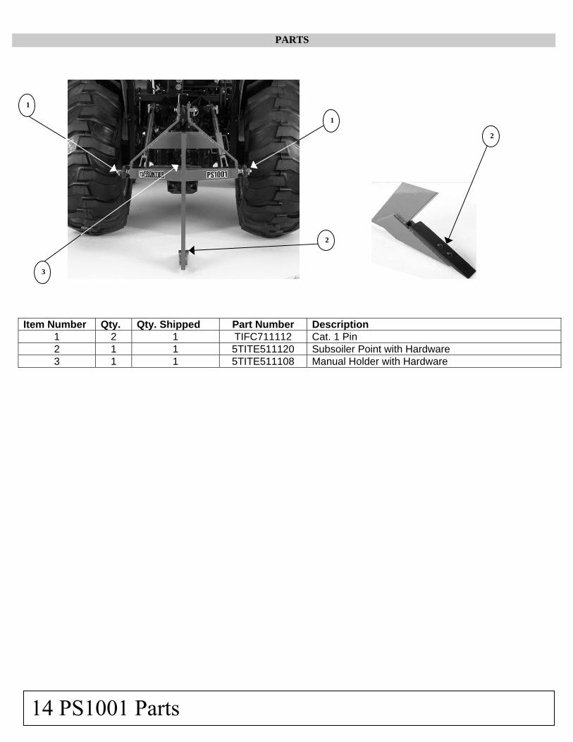
PARTS
Item Number Qty. Qty. Shipped Part Number Description 1 2 1 TIFC711112 Cat. 1 Pin 2 1 1 5TITE511120 Subsoiler Point with Hardware 3 1 1 5TITE511108 Manual Holder with Hardware
14 PS1001 Parts
1
2
2
1
3

SAFETY AND INSTRUCTIONAL DECALS
PS1001 Safety and Instruction Decals 15
5
2
4
3
1
2
3
4
5
Subsoiler Decal Sheet Part Number 5TITE511105
1

PM1001 MIDDLE BUSTER PLOW
The Middle Buster Plow can be used to plant and dig potatoes, to form ridges for other crops, or to form drainage ditches.
MIDDLE BUSTER PLOW ASSEMBLY AND ATTACHING
Make sure that the two ⅜” x 4” carriage bolts that connect the furrower of your implement are Grade #2 only. The bolts are shear bolts and protect the tractor and the implement in case an obstruction is encountered or the operating conditions become too severe. (A Grade #2 bolt is a “soft” common hardware bolt.)
NOTE: The use of a Grade 5 or higher shear bolt may result in damage to the implement.
Ensure the lower draw pins (pull pins) are installed properly for your particular tractor. For Category I hitch applications, these pins should be assembled outward.
Insert the draw pins into the ball sockets in the lower-lift arms of the tractor’s three-point hitch. Lock these in place with clinch pins (not furnished).
Attach the mast of the three point’s main frame by installing the tractor’s center link (top link) with a top link pin (not furnished).
Adjust the top-link assembly to obtain the correct angle for these implements. Check the tractor’s three-point lift arms and adjust as necessary to level the cultivator from side to side.
• Attaching Cutter to Tractor with Quick Coupler Hitch
CAUTION: To avoid bodily injury or machine damage whenever am implement is attached, put transmission in PARK position and check the full range of the hitch for interference, binding, or PTO separation. Do not stand between the tractor and the implement.
1. Slowly push hitch control lever to lower hitch until quick coupler hooks are lower than cutter hitch pins.
2. Back up tractor to unit hitch. 3. Raise hitch high enough to engage unit hitch
pins in hooks. 4. Slowly pull hitch control lever to raise unit
cutter. Check for any problems or interference. 5. Lower unit to ground and adjust if necessary. 6. To detach, reverse the steps above.
WARNING: The addition of a heavy load to your tractor may cause instability. Ensure the front of the tractor is properly counterbalanced with weights. An unstable tractor may steer poorly and possibly tip over, resulting in the operator’s injury or death. Always drive slowly!
OPERATION
Level the Middle Buster Plow by adjusting the tractor linkage in order to ensure that the plow’s shovel will run straight.
The Middle Buster Plow can be used to plant and dig potatoes, to form ridges for other crops, or to form drainage ditches.
Set your three-point hitch depth control to operate the Middle Buster Plow at the desired depth. The deeper you operate, the greater the amount of soil you will plow
16 PM1001 Middle Buster Plow

up. In dry or hard soil, you may need to make several passes.
The faster your forward speed the farther you will throw the soil from both sides of the plow shovel.
Operate at a speed that forms the hilling operation you desire.
By adjusting the length of the three-point top link, you can also adjust the pitch of the plow shovel. In moist soil conditions, the bottom of the shovel should be level, with the point slightly down. This pitch angle will also determine how much soil is moved.
LUBRICATION AND MAINTENANCE
Check all nuts and bolts to ensure they are tight.
Inspect points for any wear and damage. Replace when necessary.
After seasonal use, paint the shanks and points to prevent excessive rust during any extended periods of storage. In doing so, the scour time will be greatly reduced when you use the implement again. Inspect points for any wear and damage. Replace when necessary.
IF SHEAR BOLT HAS FAILED: If a shear bolt is ruined because of contact with an obstruction or through operation in very hard ground, replace it with a ⅜” x 4” carriage bolt, Grade #2.
NOTE: Using a Grade #5 or harder shear bolt may result in damage to the implement.
PM1001 Middle Buster Plow 17

TROUBLESHOOTING GUIDE
Problem Possible Cause Possible Remedy
Tractor will not pull implement.
1. Insufficient horsepower.
2. Soil is either too wet or too hard and dry.
3. Points are too dull.
4. Insufficient traction.
5. Attempting to operate too deep.
Use larger, heavier tractor.
Wait until soil conditions are acceptable.
Replace points.
Add ballast; increase draft control; operate at a depth that is more shallow.
Reduce depth setting and make several passes, gradually increasing the depth.
Excessive tractor tire slippage.
1. Tractor is too small.
2. Insufficient traction..
3. Operating too deep.
Use larger, heavier tractor.
Add ballast; increase draft control; or operate at a depth that is more shallow.
Reduce depth setting and make several passes, gradually increasing the depth.
Large clods. 1. Soil is too hard and dry.
2. Operating too shallow.
3. Wire or foreign object on shank.
Wait until soil conditions are acceptable.
Operate deeper.
Remove object.
Shearing bolts.
1. Wrong size shear bolt.
2. Load is too heavy.
3. Hitting rocks or obstructions.
4. Soil is too hard and dry.
Use ⅜” x 4” carriage bolt, Grade #2.
Reduce speed or operating depth.
Clear area.
Wait until soil conditions are acceptable.
Excessive point wear.
1. Soil is too dry.
2. Abrasive soil.
3. Operating too fast.
Wait until soil conditions are acceptable.
Consider having points hard surfaced by local welder.
Reduce forward speed.
18 PM1001 Troubleshooting Guide

PARTS
.
Item Number Qty. Qty. Shipped Part Number Description
1 2 1 TIFC711112 Cat. 1 Pin 2 1 1 5TITE511108 Manual Holder with Hardware 3 1 1 5TITE511115 15" Furrow with Hardware
1
3
3
PM1001 Parts 19
2

SAFETY AND INSTRUCTIONAL DECALS
20 PM1001 Safety and Instruction Decals
3
2
4
5
5
4
3
2
1
Middle Buster Decal SheetPart Number 5TITE511106
1

PC1001 ONE-ROW CULTIVATOR
The One-Row Cultivator is designed for family gardening and smaller farming operations. The cultivator is useful in preparing garden soil, planting beds and cultivating for weed control. It may also be used to remove mulch and undergrowth
ONE-ROW CULTIVATOR ASSEMBLY AND ATTACHING
Make sure the two (2) 7/16” x 1⅟₂” carriage bolts that connect the reversible cultivator point to the “C” shank are Grade #2 only. These bolts are shear bolts that protect the tractor and the implement in case an obstruction is encountered or the operating conditions are too severe.
NOTE: Use of a Grade 5 or higher shear bolt may result in damage to the cultivator.
The One-Row Cultivator is shipped completely assembled; the holes in the frame angle allow the shanks to be located with different spacing. The shanks should always be symmetrically spaced.
Ensure the lower draw pins (pull pins) are installed properly for your particular tractor. For Category I hitch applications, these pins should be assembled outward.
Insert the draw pins into the ball sockets in the lower-lift arms of the tractor’s three-point hitch. Lock these in
place with clinch pins (not furnished).
Attach the mast of the three point’s main frame by installing the tractor’s center link (top link) with a top link pin (not furnished).
Adjust the top-link assembly to obtain the correct angle for these implements. Check the tractor’s three-point lift arms and adjust as necessary to level the cultivator from side to side.
• Attaching Cutter to Tractor with Quick Coupler Hitch
CAUTION: To avoid bodily injury or machine damage whenever an implement is attached, put transmission in PARK position and check the full range of the hitch for interference, binding, or PTO separation. Do not stand between the tractor and the implement.
1. Slowly push hitch control lever to lower hitch until quick coupler hooks are lower than cutter hitch pins.
2. Back up tractor to unit hitch. 3. Raise hitch high enough to engage unit hitch
pins in hooks. 4. Slowly pull hitch control lever to raise unit
cutter. Check for any problems or interference. 5. Lower unit to ground and adjust if necessary. 6. To detach, reverse the steps above.
WARNING: The addition of a heavy load to your tractor may cause instability. Ensure the front of the tractor is properly counterbalanced with weights. An unstable tractor may steer poorly and possibly tip over, resulting in the operator’s injury or death. Always drive slowly!
PC1001 One-Row Cultivator 21

LUBRICATION AND MAINTENANCE
Check all nuts and bolts to ensure they are tight.
Inspect points for any wear and damage. Replace when necessary.
After seasonal use, paint the shanks and points to prevent excessive rust during any extended periods of storage. In doing so, the scour time will be greatly reduced when you use the implement again.
IF SHEAR BOLT HAS FAILED: If a shear bolt is ruined because of contact with an obstruction or through operation in very hard ground, replace it with a 7/16” x 1 ½” carriage bolt, Grade #2.
NOTE: Using a Grade #5 or harder shear bolt may result in damage to the implement.
TROUBLESHOOTING GUIDE
Problem Possible Cause Possible Remedy
Tractor will not pull implement.
1. Insufficient horsepower.
2. Soil is either too wet or too hard and dry.
3. Points are too dull.
4. Insufficient traction.
5. Attempting to operate too deep.
Use larger, heavier tractor.
Wait until soil conditions are acceptable.
Replace points.
Add ballast; increase draft control; operate at a depth that is more shallow.
Reduce depth setting and make several passes, gradually increasing the depth.
Excessive tractor tire slippage.
1. Tractor is too small.
2. Insufficient traction.
3. Operating too deep.
Use larger, heavier tractor.
Add ballast; increase draft control; or operate at a depth that is more shallow.
Reduce depth setting and make several passes, gradually increasing the depth.
Large clods. 1. Soil is too hard and dry.
2. Operating too shallow.
3. Wire or foreign object on shank.
Wait until soil conditions are acceptable.
Operate deeper.
Remove object.
22 PC1001 Troubleshooting Guide

PARTS
Item Number Qty. Qty Shipped Part Number Description 1 2 1 TIFC711112 Cat. 1 Pin 2 6 1 5TITE511117 C-Shank Standard for Cultivator with Hardware 3 6 1 5TITE511118 Reversible Cultivator Point with Hardware 4 1 1 5TITE511114 Support Stand 5 1 1 5TITE511119 Clinch Pin (Not Shown) 6 1 1 5TITE511108 Manual Holder with Hardware
1
2
3
4
PC1001 Parts 23
6

SAFETY AND INSTRUCTIONAL DECALS
2 4
1
5
1
3
4
5
2
One Row Cultivator Decal SheetPart Number 5TITE511104
3
24 PC1001 Safety and Instruction Decals

PB1001/PB1002 ONE- AND TWO-BOTTOM
PLOWS The One- and Two-Bottom Plows provide soil tillage for small and hobby farms. Each plow has shear-bolt protection to provide underground equipment protection.
ONE- AND TWO-BOTTOM PLOW ASSEMBLY AND ATTACHING
Remember as you read this manual that the use of the terms LEFT and RIGHT are determined by standing at the rear of the implement and looking forward.
Ensure the lower draw pins (pull pins) are installed properly for your particular tractor. For Category I hitch applications, these pins should be assembled to face outward.
Insert the draw pins into the ball sockets in the lower-lift arms of the tractor’s three-point hitch. Lock these in
place with clinch pins (not furnished).
Attach the mast of the three-point’s main frame by installing the tractor’s center link (top link) with a top-link pin (not furnished).
Adjust the top-link assembly to obtain the correct angle for the plows. Check the tractor’s three-point lift arms and adjust as necessary to level the plows from side to side.
Raise support stand on plow to operating position.
WARNING: The addition of a heavy load to your tractor may cause instability. Ensure the front of the tractor is properly counterbalanced with weights. An unstable tractor may steer poorly and possibly tip over, resulting in the operator’s injury or death. Always drive slowly! ADJUSTMENTS
The plow share on the right-hand furrow must be aligned next to the furrow in order to do a clean job.
It is recommended that the tractor’s rear wheels be set so that the right-hand tire runs in the previous furrow.
LEVELING THE PB1001/PB1002
Side-to-Side Leveling: The plow should be leveled from side to side. With the plow in the ground and the tractor’s right tire in the furrow, use the tractor’s link-arm crank to adjust the lower link arm up or down as needed to level the plow’s frame. The plow should be level in the working position.
Front-to-Rear Leveling: The plow is leveled front to rear by adjusting the length of the top link of the three-point hitch. Shorten the top link to tilt the plow forward; lengthen the top link to tilt the plow backward.
LUBRICATION AND MAINTENANCE
Check all nuts and bolts to ensure they are tight.
Inspect the plow for any loose, damaged or worn parts and adjust or replace, if required.
At the end of the working season or during any period when the plow will not be used for an extended period, it
PB1001/PB1002 Plow 25

is good practice to clean off any dirt that may have accumulated on the plow.
Ground Contacting Components: When the ground contacting components wear, they will have to be replaced. These include the plow shear, shin, landslide, wear plate, and bottom.
IF SHEAR BOLT HAS FAILED: If a shear bolt is ruined because of contact with an obstruction or through operation in very hard ground, replace it with a 7/16” x 2½” carriage bolt, Grade #5.
NOTE: Using a Grade higher than #5 shear bolt may result in damage to the implement.
STORING SAFELY
Your storage location should be level and solid in order to make hitching and unhitching easier.
For PB1001, use support stand. The plow will tip over if it is not properly supported.
Remove the top link from the plow.
Detach the lower link arms from the plow.
Ensure the plow is stable.
Thoroughly clean your plow prior to storage.
When storing between seasons, coat the soil engaging surfaces with oil or another type of rust inhibitor.
26 PB1001/PB1002 Plow

TROUBLESHOOTING GUIDE
The principle cause of plowing difficulties is improper adjustments. Should you experience problems, do not attempt to make adjustments without first consulting this section. Also, when making adjustments, try one adjustment at a time.
Problem Possible Cause Possible Remedy
Poor soil penetration.
1. Insufficient plowing depth.
2. Worn share.
3. Position of tractor selector levers.
4. Ground is hard and dry.
Shorten the tractor’s top link.
Replace share.
Refer to tractor Owner’s Manual for the proper settings.
Increase depth of head land starting furrow.
Plow ridging. 1. Front bottom too deep.
2. Front bottom too shallow.
3. Front bottom cutting too wide or too
narrow.
Shorten right-hand leveling screw or lengthen tractor’s top link.
Lengthen right-hand leveling screw or shorten tractor’s top link.
Adjust plow properly by correcting wheel and cross shaft settings.
Poor trash coverage.
1. Bottoms not scouring. Clean bottoms frequently until land polish is obtained.
Bent plow beam or frame.
1. Hard shearbolt.
2. Hitting hidden objects.
3. Using tractor that is too large or one
that is heavily weighted and has four-wheel drive.
Replace bent parts and install proper shearbolt.
Know your soil’s condition. Use slow speed when soil conditions are unknown.
Slow down and use extra care.
Plow pulls heavy. 1. Plow running on nose.
2. Excessive landside pressure.
3. Excessive tractor wheel slippage.
4. Bent plow frame or beam.
5. Ground is hard and dry.
Lengthen top link
Incorrect tractor wheel or cross shaft setting. Rear landside should run approximately ¼” to ½” from furrow wall.
Refer to tractor’s Owner’s Manual to correct operation of depth control. Add weight to tractor, if necessary. Reduce air pressure in rear tires. May need to use larger tractor.
Replace bent parts; check shearbolt.
Use larger tractor.
PB1001/PB1002 Troubleshooting Guide 27

TROUBLESHOOTING GUIDE (Continued)
Problem Possible Cause Possible Remedy
Furrows rolling back. 1. Furrows too deep for width of bottom.
Reduce plowing depth.
Broken or misplaced furrows.
1. Plowing speed too high. Reduce tractor speed.
Plow comes out of ground.
1. Tractor’s draft control is lifting plow. 2. Soil is too hard.
Set tractor draft control.
Use larger tractor.
Side pull. 1. Tractor front pulls towards furrow.
Add front-end weight.
Bottoms won’t scour. 1. New bottoms.
2. Plow running on nose.
3. Plow running crooked.
Polish with a sanding wheel, following the flow of the dirt over the plow bottoms.
Lengthen top link.
Place the right-hand link pin in the cross shaft’s center adjustment hole. Obtain the proper width of cut for the front bottom at this setting by making cross shaft and tractor wheel adjustments. The wheel track should be adjusted so that the inside of the right-hand front tire is in line with the inside of the right-hand rear tire.
Plow crowding (not running straight).
1. Plow running on nose.
2. Plow crowding to the left.
3. Plow crowding to the right.
4. Plow goes too deep.
5. Plow won’t stay down.
6. Front bottom cutting too narrow or too wide.
7. Worn share.
Improper wheel and cross shaft setting.
Lengthen the tractor’s top link.
Front bottom too deep -- shorten right-hand leveling screw or lengthen the tractor’s top link.
Front bottom too shallow – lengthen right-hand leveling screw or shorten the tractor’s top link
Lengthen top link to reduce depth.
Shorten top link to increase depth.
Using the adjustable link pinholes, adjust the plow to the right or left so that the front bottom cuts to the proper width.
NOTE: This adjustment should not be used to compensate for improper wheel and cross-shaft adjustments.
Replace share.
Set wheels and cross shaft properly.
28 PB1001/PB1002 Troubleshooting Guide

PARTS
Item Number Qty. Qty. Shipped Part Number Description 1 1 1 5TITE511131 Plow Spacer with Hardware 2 1 1 5TITE511130 Plow RH A-Arm 3 1 1 5TITE511129 Plow LH A-Arm 4 2 1 5TITE511146 U-Bolt with Nuts and Washers 5 1 1 5TITE511113 Plow Cross Bar 6 2 1 5TITE511149 Cross Bar Angle Brace 7 8 2 5TITE511147 Hex Head Bolt Grade #2 with Nut and Washer 8 1 1 5TITE511108 Manual Holder with Hardware
PB1001 Parts 29
5
4 2
8
1 3
7
4
6
6

PARTS
Item Number Qty.
Qty. Shipped Part Number Description 1 1 1 5TITE511143 Plow Back Brace 2 1 1 5TITE511119 Clinch Pin 3 2 1 TIFC711112 Cat. 1 Pin 4 1 1 5TITE511114 Support Stand 5 1 1 5TITE511134 Frog with Hardware 6 1 1 5TITE511138 Hex Head Bolt Grade #2 with Nut and Washer 7 2 2 5TITE511132 Drop Beam Mounting Plate 8 2 1 5TITE511137 Hex Head Bolt Grade #2 with Nut and Washer 9 8 2 5TITE511147 Hex Head Bolt Grade #2 with Nut and Washer 10 1 5 5TITE511142 Plow Shear Bolt with Nut 11 1 1 5TITE511145 Hex Head Bolt Grade #2 with Nut 12 1 1 5TITE511140 Rock Slide with Hardware
30 PB1001 Parts
8
2
3
4 9
8
11 12
5
1
6
7
9
9
9 (x4)
10 9

PARTS
Item Number Qty. Qty. Shipped Part Number Description 1 1 1 5TITE511111 14" Plow Mold Board with Hardware 2 1 1 5TITE511110 14" Plow Shin with Hardware 3 1 1 5TITE511109 14" Plow Share with Hardware 4 1 1 5TITE511141 Rock Slide Angle Brace with Hardware
PB1001 Parts 31
2
3
1 4

SAFETY AND INSTRUCTIONAL DECALS
32 PB1001 Safety and Instruction Decals
1
2 4
1
3
5
One Bottom Plow Decal Sheet Part Number 5TITE511101
2
3
4
5

PARTS
Item Number Qty. Qty. Shipped Part Number Description 1 1 1 5TITE511143 Plow Back Brace 2 3 1 5TITE511138 Hex Head Bolt Grade #2 with Nut and Washer 3 2 1 5TITE511135 Hex Head Bolt Grade #2 with Nut and Washer 4 2 1 5TITE511137 Hex Head Bolt Grade #2 with Nut and Washer 5 2 1 5TITE511146 U-Bolt with Nuts, Washers 6 4 2 5TITE511132 Drop Beam Mounting Plate 7 12 2 5TITE511147 Hex Head Bolt Grade #2 with Nut and Washer 8 2 5 5TITE511142 Plow Shear Bolt with Nut 9 2 1 5TITE511145 Hex Head Bolt Grade #2 with Nut and Washer
10 1 1 5TITE511139 Short Rock Share with Hardware 11 2 1 TIFC711112 Cat. 1 Pin 12 2 1 5TITE511134 Frog with Hardware 13 2 1 5TITE511149 Cross Bar Angle Brace 14 2 1 5TITE511111 14” Plow Mold Board with Hardware 15 2 1 5TITE511110 14” Plow Shin with Hardware 16 2 1 5TITE511109 14” Plow Share with Hardware 17 1 1 5TITE511140 Rock Slide with Hardware
PB1002 Parts 33
4
7
5
7
15 10
13
11
1
2 4 2
6
7
8 7
12
8 7
6
9
16
12
14 3 7
16 7
9
17

PARTS
Item Number Qty.
Qty. Shipped Part Number Description 1 1 1 5TITE511131 Plow Spacer with Hardware 2 1 1 5TITE511130 Plow RH A-Arm (PB1001, PB1002) 3 1 1 5TITE511129 Plow LH A-Arm (PB1001, PB1002) 4 2 1 5TITE511146 U-Bolt with Nuts, Washers 5 1 1 5TITE511113 Plow Cross Bar 6 1 1 5TITE511108 Manual Holder with Hardware 7 1 1 5TITE511140 Rock Slide with Hardware 8 1 1 5TITE511141 Rock Slide Angle Brace with Hardware
34 PB1002 Parts
1 2 3
4
5
6
7
4
8

SAFETY AND INSTRUCTIONAL DECALS
PB1002 Safety and Instruction Decals 35
1
2 3
1
5
4
3
2
1
4
5
Two Bottom Plow Decal Sheet Part Number 5TITE511102

PC1072 FIELD CULTIVATOR
The Field Cultivator is best suited for seedbed preparation, weed eradication, and fallow cultivation and is equipped with spring steel shanks with mounting holes for replaceable shovel or sweep tools.
FIELD CULTIVATOR ASSEMBLY AND ATTACHING
Refer to the Parts Drawing in this manual for step-by-step assembly information for this implement.
Insert the draw pins into the ball sockets in the lower-lift arms of the tractor’s three-point hitch. Lock these in place with clinch pins (not furnished).
Attach the mast of the three-point’s main frame by installing the tractor’s center link (top link) with a top link pin (not furnished).
Adjust the top-link assembly to obtain the correct angle for these implements. Check the tractor’s three-point lift arms and adjust as necessary to level the cultivator from side to side.
• Attaching Cutter to Tractor with Quick Coupler Hitch
CAUTION: To avoid bodily injury or machine damage whenever an implement is attached, put transmission in PARK position and check the full range of the hitch for interference, binding, or PTO separation. Do not stand between the tractor and the implement.
1. Slowly push hitch control lever to lower hitch until quick coupler hooks are lower than cutter hitch pins.
2. Back up tractor to unit hitch. 3. Raise hitch high enough to engage unit hitch
pins in hooks. 4. Slowly pull hitch control lever to raise unit
cutter. Check for any problem or interference. 5. Lower unit to ground and adjust if necessary. 6. To detach, reverse the steps above.
WARNING: The addition of a heavy load to your tractor may cause instability. Ensure the front of the tractor is properly counterbalanced with weights. An unstable tractor may steer poorly and possibly tip over, resulting in the operator’s injury or death. Always drive slowly! LEVELING THE CULTIVATOR FRAME
For best results, when leveling your cultivator, position the tractor and the attached cultivator on a level surface.
For side-to-side leveling, start with the field cultivator raised 4” to 6” from the level surface. Standing at the rear of the tractor, sight across the top of the cultivator frame and the tractor’s axle. Adjust the lift links on the tractor’s three-point hitch to level the frame from side to side.
When making your initial adjustment, stand at the side of the cultivator and sight across the top of the cultivator and the level surface.
If your cultivator frame is not level from front to back when sighting the ground line, turn the center link on the tractor either in or out until the cultivator frame is parallel to the ground line.
36 PC1072 Field Cultivator

Further front to back adjustment may be required after the cultivator is operated in the field. When properly leveled, the cultivator will enter the ground to a uniform depth.
LUBRICATION AND MAINTENANCE
Check all nuts and bolts to ensure they are tight.
Inspect points for any wear and damage. Replace when necessary.
After seasonal use, paint the shanks and points to prevent excessive rust during any extended periods of storage. In doing so, the scour time will be greatly reduced when you use the implement again.
TROUBLESHOOTING GUIDE
Problem Possible Cause Possible Remedy
Tractor will not pull implement.
1. Insufficient horsepower.
2. Soil is either too wet or too hard and dry.
3. Points are too dull.
4. Insufficient traction.
5. Attempting to operate too deep.
Use larger, heavier tractor.
Wait until soil conditions are acceptable.
Replace points.
Add ballast; increase draft control; operate at a depth that is more shallow.
Reduce depth setting and make several passes, gradually increasing the depth.
Excessive tractor tire slippage.
1. Tractor is too small.
2. Insufficient traction.
3. Operating too deep.
Use larger, heavier tractor.
Add ballast; increase draft control; or operate at a depth that is more shallow.
Reduce depth setting and make several passes, gradually increasing the depth.
Excessive point wear.
1. Soil is too dry.
2. Abrasive soil
3. Operating too fast.
Wait until soil conditions are acceptable.
Consider having points resurfaced by local welder.
Reduce speed.
PC1072 Troubleshooting Guide 37

PARTS
Item Number Qty. Qty. Shipped Part Number Description
1 1 1 5TITE511108 Manual Holder with Hardware 2 13 1 5TITE511121 Spade with Hardware 3 13 1 5TITE511122 S-Tine with Hardware 4 13 1 5TITE511123 Tine Mounting Bracket 5 2 1 5TITE511127 Grade #5 Bolt with Nut and Washer
6 0 1 5TITE511151
Sweep Point with Hardware (Extra) (Does not ship with unit-requires 13 for full set)
7 0 1 5TITE511152
Danish Type Point with Hardware(Extra) (Does not ship with unit-requires 13 for full set)
Sweep Point Danish Type Point
(Extra) (Extra)
2
1
3
5
4
38 PC1072 Parts
6 7

PARTS
Item Number Qty. Qty. Shipped Part Number Description 1 2 1 5TITE511128 Grade #5 Bolt with Nut and Washer 2 1 1 5TITE511124 Back Brace 3 1 1 5TITE511126 LH A-Arm 4 1 1 5TITE511125 RH A-Arm
PC1072 Parts 39
2
1
3
4

SAFETY AND INSTRUCTIONAL DECALS
5
1
2
3
4
1
1 4
5
5
2
Field Cultivator Decal SheetPart Number 5TITE511103
40 PC1072 Safety and Instruction Decals
3

WARRANTY
Tarter Industries, Inc., (hereafter known as “Manufacturer”) warrants to the original purchaser that the implement is free from defects in both material and workmanship under normal use and service for a period of one (1) year for noncommercial use. Any use by commercial, state, and municipalities will void warranty.
This Warranty is limited to the replacement of any defective part by the Manufacturer and the installation by the dealer of any such replacement part, and does not cover common wear such as blades, belts, tines, etc. Replacement or repair parts in the equipment covered by this limited warranty are warranted for 90 days from the date of purchase by the customer of such part or to the expiration of the applicable new equipment warranty period, whichever occurs first. Manufacturer reserves the right to inspect any implement or parts which are claimed to have been defective in either material or workmanship.
This Warranty shall not be interpreted to render the Manufacturer liable for damages of any kind, direct, consequential, or contingent to property. Furthermore, manufacturer shall not be liable for damages resulting from any cause beyond its reasonable control. This Warranty does not extend to loss of crops, any expense or loss for labor, supplies, rental machinery, or for any other reason.
This Warranty does not apply to any part or product which in the Manufacturer’s judgment shall have been misused or damaged by accident or lack of normal maintenance or care, or which has been used for purpose for which the product is not designed. Misuse also specifically includes failure to properly maintain equipment as specified.
Claims under this Warranty must be made to an authorized Frontier dealer, and must be submitted within 30 days of failure. Manufacturer reserves the right to make changes in materials or design of the product at any time without notice.
This Warranty is extended solely to the original purchaser of the product. Should the original purchaser sell or otherwise transfer this product to a third party, this Warranty does not transfer to the third party purchaser in any way. There are no third party beneficiaries of this Warranty.
This Warranty will not be honored until the product is registered with the Manufacturer via the Frontier Marketplace by an authorized Frontier dealer.
KEEP FOR YOUR RECORDS
Record the model number, serial number, and the date of purchase. This information will be helpful to your dealer if parts or service are required.
MODEL NUMBER __________________________________________
SERIAL NUMBER _____________________________________________
DATE OF PURCHASE _____________________________________________
DEALER _____________________________________________
NOTE: Please read this Operator’s Manual. Read and understand the Warranty Statement above.
Warranty 41

Intentional Blank Page
42

Intentional Blank Page
43

PART NUMBER 5TITE511107