Embed Size (px)
Citation preview
Published: April 28, 2011
r 2011 American Chemical Society 7307 dx.doi.org/10.1021/la200396v | Langmuir 2011, 27, 7307–7313
ARTICLE
pubs.acs.org/Langmuir
Sliding of Water Droplets on Hydrophobic Surfaces withVarious Hydrophilic Region SizesTsutomu Furuta,† Munetoshi Sakai,‡ Toshihiro Isobe,† Sachiko Matsushita,† and Akira Nakajima*,†,‡
†Department of Metallurgy and Ceramic Science, Graduate School of Science and Engineering, Tokyo Institute of Technology,2-12-1 O-okayama, Meguro-ku, Tokyo 152-8552, Japan‡Kanagawa Academy of Science and Technology, 308 East, Kanagawa Science Park, 3-2-1 Sakado, Takatsu-ku, Kawasaki-shi,Kanagawa 213-0012, Japan
bS Supporting Information
I. INTRODUCTION
Recently, hydrophobic coatings have attracted much attentionfor eventual use in various industries. Hydrophobicity of solidsurfaces can be evaluated from static wettability and dynamicwettability.1 The water contact angle is commonly used as acriterion for evaluating static wettability. Although the slidingangle (the tilt angle at which the water droplet of a certain volumestarts to slide down) and the contact angle hysteresis (theabsolute value of the difference of cosines between advancing(θa) and receding (θr) contact angles) reflect the motion ordeformation of droplets, it is not an index of dynamic hydro-phobicity, such as sliding acceleration or velocity, because theseare thermodynamic properties and are not a function of time.However, the sliding velocity has played an important role whenpractical sliding behavior is discussed. Studies of the relationbetween surface properties and sliding velocity or accelerationhave been increasing gradually.2�4
That surface defects affect the motion of water droplets andincrease sliding angle and the contact angle hysteresis is well-known.5 This phenomenon is commonly designated as the“pinning effect”.6 The pinning effect is separable into twocategories:7,8 the physical pinning effect, which originates fromsurface roughness, and the chemical pinning effect, which resultsfrom chemical heterogeneity on the surface. To date, variousstudies of the pinning effect have been conducted.9�19 Very
recently, we demonstrated that the sliding behavior of waterdroplets is affected by the surface roughness, even of scale around10 nm, and demonstrated that highly physical homogeneity(average surface roughness (Ra) less than 1.0 nm) is necessaryto avoid the effect of physical pinning completely.4 However, fewexperimental studies have examined the chemical pinning effectwith avoidance of physical roughness. Moreover, no reports havedescribed the effect of surface chemical defect sizes on thecontact angle hysteresis, sliding angle, or sliding velocity withsustained defect shape and density in the surface.
Patterned coatings of various types have been prepared usingself-assembled monolayers (SAMs) and photolithography.20�23
Sugimura et al. reported the preparation of chemically patternedSAM coatings formed by photolithography with vacuum ultra-violet (VUV) irradiation.20 The wettability on such surfaces hasbeen investigated in recent years.21�23 The stick�slip motion ofthe sliding droplet on the horizontal stripe-patterned coating hasbeen reported. For this study, we prepared four hexagonallypatterned surfaces, which included homothetic hydrophilic areasin different sizes, using a photolithography process with ahydrophobic SAM coating of a silane coupling agent. Then,
Received: January 29, 2011Revised: March 25, 2011
ABSTRACT: Four patterned surfaces with hydrophilic areas ofdifferent sizes were prepared using photolithography with asmooth octadecyltrimethoxysilane (ODS) hydrophobic coating.The hydrophilic area in the surfaces was aligned hexagonally witha constant area fraction. The sliding angle and contact anglehysteresis of the water droplets increased concomitantly withincreasing pattern size. The increase of the contact line distortionbetween defects at the receding side plays an important role in thistrend. The droplet sliding velocity also increased concomitantlywith increasing pattern size. This trend was simulated by a simpleflow model. The contribution of the interface between the ODSregion and the hydrophilic area was deduced from this trend. Thisstudy demonstrated the different size dependency of the chemicalsurface defects for sliding behavior between the critical moment at which a droplet slides down and the period when a droplet issliding.
7308 dx.doi.org/10.1021/la200396v |Langmuir 2011, 27, 7307–7313
Langmuir ARTICLE
the effects of the size-dependence of the chemical surface defectsfor contact-angle hysteresis, sliding angle, and sliding velocitywere investigated.
II. EXPERIMENTAL SECTION
We prepared smooth hydrophobic SAM coatings using octadecyl-trimethoxysilane (ODS, CH3(CH2)17Si(OCH3)3; Aldrich ChemicalCo. Inc., Milwaukee, WI) for the chemically patterned coating. TheSAMwas prepared using chemical vapor deposition (CVD). The surfaceof a Si(100) wafer (Aki Corp., Miyagi, Japan) was washed using ethanoland acetone each for 7 min. It was then precleaned using vacuumultraviolet (VUV) light (λ = 172 nm with power density of around7 mW cm�2, UEM20-172; Ushio Inc., Tokyo, Japan) irradiation for 15min. Smooth hydrophobic SAM coatings were obtained by heating theSi wafer with 20 μL of ODS in a Petri dish by flowing N2 at 150 �C for 60min. After the coating was rinsed with toluene, acetone, and water, itwas dried.Four chemically patterned coatings were prepared from the ODS
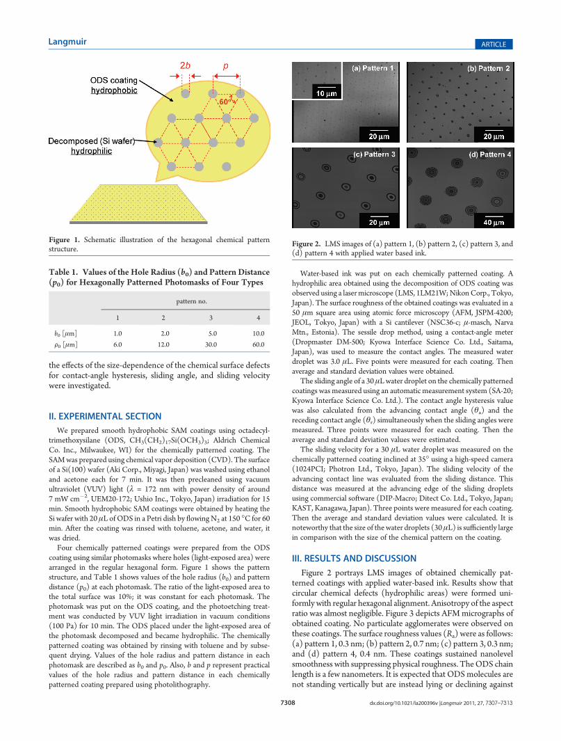
coating using similar photomasks where holes (light-exposed area) werearranged in the regular hexagonal form. Figure 1 shows the patternstructure, and Table 1 shows values of the hole radius (b0) and patterndistance (p0) at each photomask. The ratio of the light-exposed area tothe total surface was 10%; it was constant for each photomask. Thephotomask was put on the ODS coating, and the photoetching treat-ment was conducted by VUV light irradiation in vacuum conditions(100 Pa) for 10 min. The ODS placed under the light-exposed area ofthe photomask decomposed and became hydrophilic. The chemicallypatterned coating was obtained by rinsing with toluene and by subse-quent drying. Values of the hole radius and pattern distance in eachphotomask are described as b0 and p0. Also, b and p represent practicalvalues of the hole radius and pattern distance in each chemicallypatterned coating prepared using photolithography.
Water-based ink was put on each chemically patterned coating. Ahydrophilic area obtained using the decomposition of ODS coating wasobserved using a lasermicroscope (LMS, 1LM21W;NikonCorp., Tokyo,Japan). The surface roughness of the obtained coatings was evaluated in a50 μm square area using atomic force microscopy (AFM, JSPM-4200;JEOL, Tokyo, Japan) with a Si cantilever (NSC36-c; μ-masch, NarvaMtn., Estonia). The sessile drop method, using a contact-angle meter(Dropmaster DM-500; Kyowa Interface Science Co. Ltd., Saitama,Japan), was used to measure the contact angles. The measured waterdroplet was 3.0 μL. Five points were measured for each coating. Thenaverage and standard deviation values were obtained.
The sliding angle of a 30μLwater droplet on the chemically patternedcoatings was measured using an automatic measurement system (SA-20;Kyowa Interface Science Co. Ltd.). The contact angle hysteresis valuewas also calculated from the advancing contact angle (θa) and thereceding contact angle (θr) simultaneously when the sliding angles weremeasured. Three points were measured for each coating. Then theaverage and standard deviation values were estimated.
The sliding velocity for a 30 μL water droplet was measured on thechemically patterned coating inclined at 35� using a high-speed camera(1024PCI; Photron Ltd., Tokyo, Japan). The sliding velocity of theadvancing contact line was evaluated from the sliding distance. Thisdistance was measured at the advancing edge of the sliding dropletsusing commercial software (DIP-Macro; Ditect Co. Ltd., Tokyo, Japan;KAST, Kanagawa, Japan). Three points were measured for each coating.Then the average and standard deviation values were calculated. It isnoteworthy that the size of the water droplets (30μL) is sufficiently largein comparison with the size of the chemical pattern on the coating.
III. RESULTS AND DISCUSSION
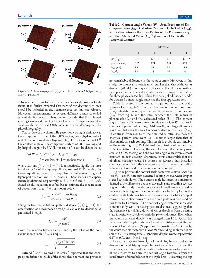
Figure 2 portrays LMS images of obtained chemically pat-terned coatings with applied water-based ink. Results show thatcircular chemical defects (hydrophilic areas) were formed uni-formly with regular hexagonal alignment. Anisotropy of the aspectratio was almost negligible. Figure 3 depicts AFMmicrographs ofobtained coating. No particulate agglomerates were observed onthese coatings. The surface roughness values (Ra) were as follows:(a) pattern 1, 0.3 nm; (b) pattern 2, 0.7 nm; (c) pattern 3, 0.3 nm;and (d) pattern 4, 0.4 nm. These coatings sustained nanolevelsmoothness with suppressing physical roughness. TheODS chainlength is a few nanometers. It is expected that ODSmolecules arenot standing vertically but are instead lying or declining against
Table 1. Values of the Hole Radius (b0) and Pattern Distance(p0) for Hexagonally Patterned Photomasks of Four Types
pattern no.
1 2 3 4
b0 [μm] 1.0 2.0 5.0 10.0
F0 [μm] 6.0 12.0 30.0 60.0
Figure 1. Schematic illustration of the hexagonal chemical patternstructure.
Figure 2. LMS images of (a) pattern 1, (b) pattern 2, (c) pattern 3, and(d) pattern 4 with applied water based ink.
7309 dx.doi.org/10.1021/la200396v |Langmuir 2011, 27, 7307–7313
Langmuir ARTICLE
substrate on the surface after chemical vapor deposition treat-ment. It is further expected that part of the decomposed areashould be included in the scanning area on this size relation.However, measurements at several different points providedalmost identical results. Therefore, we consider that the obtainedcoatings sustained nanolevel smoothness with suppressing phy-sical roughness even if ODS molecules were decomposed byphotolithography.
The surface of the chemically patterned coating is definable asthe compound surface of the ODS coating area (hydrophobic)and the decomposed area (hydrophilic). From Cassie’s model,24
the contact angle on the compound surface of ODS coating andhydrophilic region by UV illumination (θ*) can be described as
cos θ�¼ fUv cos θUV þ fODS cos θODS
¼ fUV cos θUV þ ð1� fUVÞcos θODS ð1Þwhere fUV and fODS (= 1 � fUV), respectively, signify the areafractions (<1) of the hydrophilic region and ODS coating. Inthose equations, θUV and θODS denote the contact angle ofhydrophilic region and ODS coating. These values are experi-mentally obtained, respectively, as θUV = 29� and θODS = 100�.Based on this equation, it is feasible to estimate the area fractionof decomposed area (fUV), as shown below.
fUV ¼ cos θ� � cos θODScos θUV � cos θODS
ð2Þ
Using the hole radius (b) and pattern distance (p) (Figure 1), thearea fraction of decomposed area (fUV) can also be described aspresented in eq 3.
fUV ¼ πb2
p2 sin60�ð3Þ
From the relation between eqs 2 and 3, the value of the holeradius is calculable (bcal) as eq 4.
bcal ¼ffiffiffiffiffiffiffiffiffiffiffiffiffiffiffiffiffiffiffiffiffiffiffiffiffifUV p2 sin 60�
π
sð4Þ
Extrand25 and Gao and McCarthy26 reported that the com-position difference inside of the three-phase contact line provides
no remarkable difference in the contact angle. However, in thisstudy, the chemical pattern is much smaller than that of the waterdroplet (3.0 μL). Consequently, it can be that the compositionratio placed under the water contact area is equivalent to that onthe three phase contact line. Therefore, we applied Cassie’s modelfor obtained contact angle values as the first approximation.
Table 2 presents the contact angle on each chemicallypatterned coating (θ*), the area fraction of decomposed area(fUV) calculated from eq 2, the calculated value of hole radius(bcal) from eq 4, and the ratio between the hole radius ofphotomask (b0) and the calculated value (bcal). The contactangle values (θ*) were almost equivalent (85�87�) to eachchemically patterned coating. Additionally, no large differencewas found between the area fractions of decomposed area (fUV).In contrast, from results of the hole radius ratio (bcal/b0), thechemical pattern sizes were 1.4�1.6 times larger than that ofphotomask on each coating. This result is probably attributableto the scattering of VUV light and the diffusion of ozone fromVUV irradiation. However, the ratio between the decomposedarea and ODS coating, and the contact angle values were almostconstant on each coating. Therefore, it was conceivable that theobtained coatings could be defined as surfaces that includedchemical defects with the same density as that when the slidingbehaviors of water droplet were mutually compared.
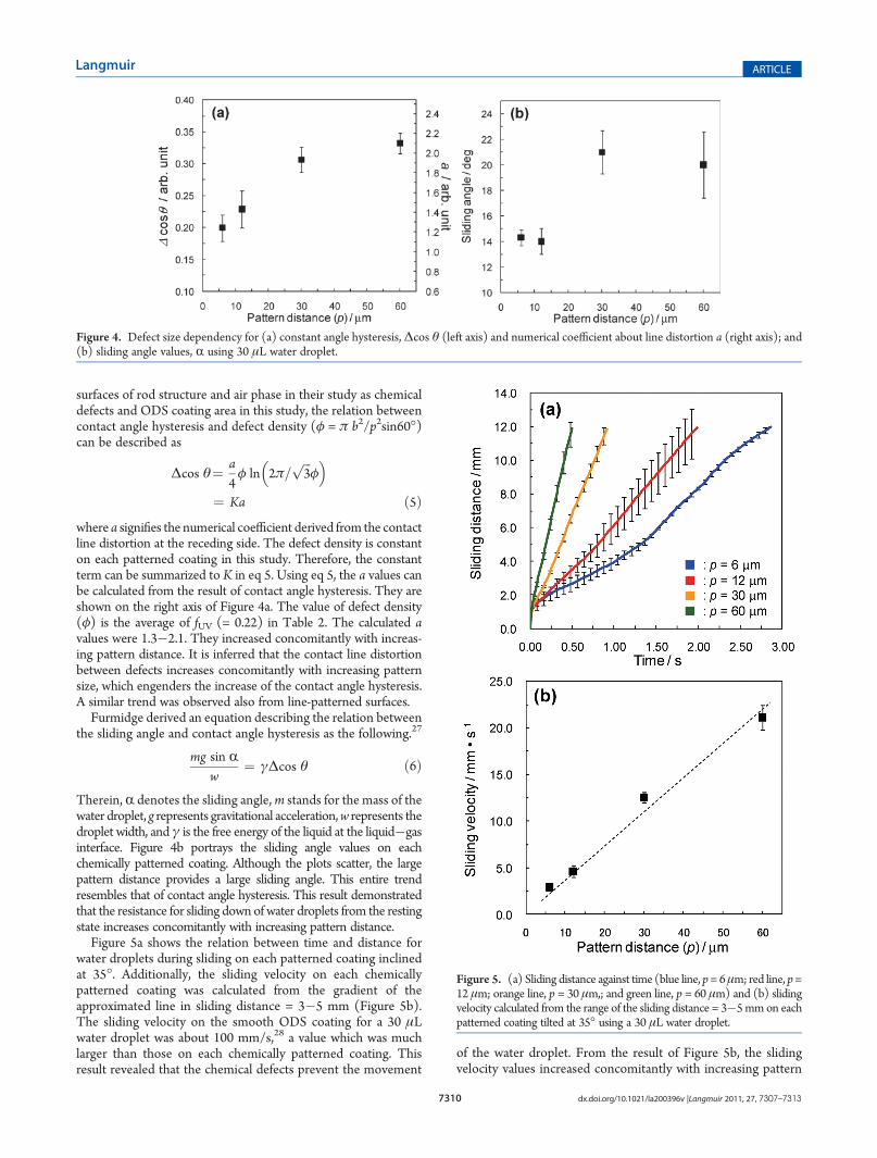
Figure 4a portrays the contact angle hysteresis values (Δcos θ =|cos θa� cos θr|) on each patterned coating when a water dropletstarted to slide down. The contact angle hysteresis is sometimesdefined as the difference between advancing and receding contactangles. In this study, the absolute value of the difference of cosinebetween advancing and receding contact angles is applied as thecontact angle hysteresis because the force balance when a dropletcommences to slide down on an inclined plate was discussed onthis form by Furmidge.27 The contact angle hysteresis increasedconcomitantly with increasing pattern distance, suggesting thatthe resistance for sliding down of water droplets from a restingstate is positively correlated with the pattern distance. Even whenthe volume of water droplet was changed from 10 to 75 μL, thetrend of contact angle hysteresis for pattern distance exhibited analmost identical trend (Supporting Information). Additionally,the contact angle hysteresis (Δcos θ) and sliding angle values onsmoothODS coating for a 30 μLwater droplet were, respectively,0.17 ( 0.02 and 10 ( 1 [deg].
Reyssat and Qu�er�e investigated the sliding behavior of waterdroplets on a highly hydrophobic surface with circular rodlikestructures, and discussed the relation between the surface densityof rod structures (φ) and the contact angle hysteresis from theequilibrium of force balance at the triple line.11 Assuming the top
Table 2. Contact Angle Values (θ*), Area Fractions of De-composed Area (fUV), Calculated Values ofHole Radius (bcal),and Ratios between the Hole Radius of the Photomask (b0)and the Calculated Value (bcal/b0) on Each ChemicallyPatterned Coating
pattern no.
1 2 3 4
θ* [deg] 87 ( 3 87 ( 5 85 ( 3 87 ( 2
fUV [arb. unit] 0.22 0.21 0.24 0.21
bcal [μm] 1.5 2.9 7.8 14.4
bcal/b0 1.5 1.4 1.6 1.4
Figure 3. AFMmicrographs of (a) pattern 1, (b) pattern 2, (c) pattern 3,and (d) pattern 4.
7310 dx.doi.org/10.1021/la200396v |Langmuir 2011, 27, 7307–7313
Langmuir ARTICLE
surfaces of rod structure and air phase in their study as chemicaldefects and ODS coating area in this study, the relation betweencontact angle hysteresis and defect density (φ = π b2/p2sin60�)can be described as
Δcos θ¼ a4φ ln 2π=
ffiffiffi3
pφ
� �¼ Ka ð5Þ
where a signifies the numerical coefficient derived from the contactline distortion at the receding side. The defect density is constanton each patterned coating in this study. Therefore, the constantterm can be summarized to K in eq 5. Using eq 5, the a values canbe calculated from the result of contact angle hysteresis. They areshown on the right axis of Figure 4a. The value of defect density(φ) is the average of fUV (= 0.22) in Table 2. The calculated avalues were 1.3�2.1. They increased concomitantly with increas-ing pattern distance. It is inferred that the contact line distortionbetween defects increases concomitantly with increasing patternsize, which engenders the increase of the contact angle hysteresis.A similar trend was observed also from line-patterned surfaces.
Furmidge derived an equation describing the relation betweenthe sliding angle and contact angle hysteresis as the following.27
mg sin Rw
¼ γΔcos θ ð6Þ
Therein, R denotes the sliding angle,m stands for the mass of thewater droplet, g represents gravitational acceleration,w represents thedroplet width, and γ is the free energy of the liquid at the liquid�gasinterface. Figure 4b portrays the sliding angle values on eachchemically patterned coating. Although the plots scatter, the largepattern distance provides a large sliding angle. This entire trendresembles that of contact angle hysteresis. This result demonstratedthat the resistance for sliding down of water droplets from the restingstate increases concomitantly with increasing pattern distance.
Figure 5a shows the relation between time and distance forwater droplets during sliding on each patterned coating inclinedat 35�. Additionally, the sliding velocity on each chemicallypatterned coating was calculated from the gradient of theapproximated line in sliding distance = 3�5 mm (Figure 5b).The sliding velocity on the smooth ODS coating for a 30 μLwater droplet was about 100 mm/s,28 a value which was muchlarger than those on each chemically patterned coating. Thisresult revealed that the chemical defects prevent the movement
of the water droplet. From the result of Figure 5b, the slidingvelocity values increased concomitantly with increasing pattern
Figure 4. Defect size dependency for (a) constant angle hysteresis,Δcos θ (left axis) and numerical coefficient about line distortion a (right axis); and(b) sliding angle values, R using 30 μL water droplet.
Figure 5. (a) Sliding distance against time (blue line, p= 6μm; red line, p=12 μm; orange line, p = 30 μm,; and green line, p = 60 μm) and (b) slidingvelocity calculated from the range of the sliding distance = 3�5mmon eachpatterned coating tilted at 35� using a 30 μL water droplet.
7311 dx.doi.org/10.1021/la200396v |Langmuir 2011, 27, 7307–7313
Langmuir ARTICLE
distance. This result implies that the moving resistance for waterdroplets during sliding decreases concomitantly with increasingpattern distance. This trend is opposite to that for the contactangle hysteresis and sliding angle.
In the measurement of sliding angle or contact angle hysteresis,the surface tilting rate is small. The droplet moves gradually fromthe resting state, and the removal of the rear side of the triple line isimportant in this case. For sliding velocity measurements, thesliding droplets are set on the slopewith an angle that is larger thanthe critical (sliding) angle. Therefore, the rapid increase in movingvelocity occurs from an early stage of sliding, which is expected toprovide slippage at the solid�liquid boundary for the droplets,especially for the surface with a large sliding velocity.3,28�30 Theexistence of a slipping element is reported also on octadecylsilaneSAM coatings.28,31 On the hydrophilic region produced by VUVirradiation, the slipping velocity is expected to be quite small: it isassumed to be almost zero compared to that of the ODS region.Consequently, water at the solid�liquid interface will flow mainlyon theODS region, and the resistance for the flowwill arise mainlyfrom the interface between the ODS region and the hydrophilicone. In this study, the sum of the hydrophilic region is constantamong patterns 1�4. The length of interface contained per unitarea (φIL) can be described as
φIL¼2πb
p2 sin 60�¼ k
1p
ð7Þ
Because the ratio between defect radius and pattern distance isconstant on each chemically patterned coating, the relation
between φIL and 1/p is linear (k is a constant term). When theflow resistance increases concomitantly with increasing φIL, it isexpected that the sliding velocity increases concomitantly withincreasing pattern distance (p). Figure 5b shows an almost exactlinear regression. The relation supports this interpretation.
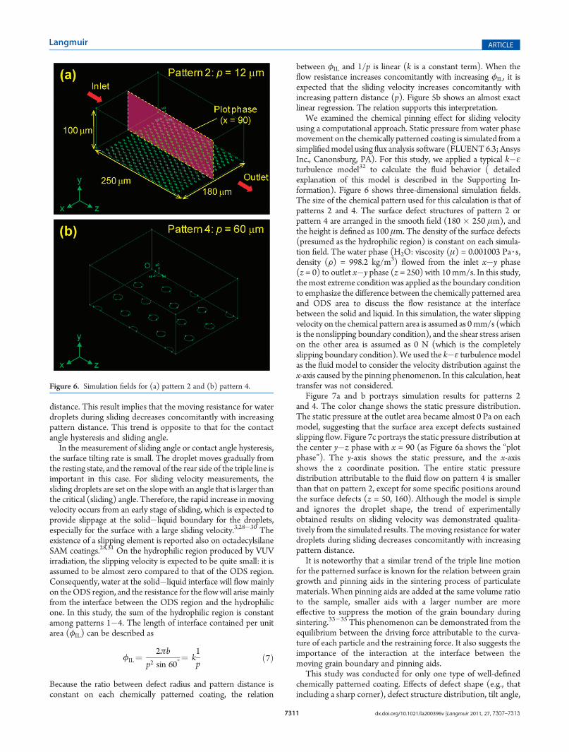
We examined the chemical pinning effect for sliding velocityusing a computational approach. Static pressure from water phasemovement on the chemically patterned coating is simulated from asimplifiedmodel using flux analysis software (FLUENT6.3; AnsysInc., Canonsburg, PA). For this study, we applied a typical k�εturbulence model32 to calculate the fluid behavior ( detailedexplanation of this model is described in the Supporting In-formation). Figure 6 shows three-dimensional simulation fields.The size of the chemical pattern used for this calculation is that ofpatterns 2 and 4. The surface defect structures of pattern 2 orpattern 4 are arranged in the smooth field (180 � 250 μm), andthe height is defined as 100 μm. The density of the surface defects(presumed as the hydrophilic region) is constant on each simula-tion field. The water phase (H2O: viscosity (μ) = 0.001003 Pa 3 s,density (F) = 998.2 kg/m3) flowed from the inlet x�y phase(z = 0) to outlet x�y phase (z = 250) with 10mm/s. In this study,themost extreme conditionwas applied as the boundary conditionto emphasize the difference between the chemically patterned areaand ODS area to discuss the flow resistance at the interfacebetween the solid and liquid. In this simulation, the water slippingvelocity on the chemical pattern area is assumed as 0mm/s (whichis the nonslipping boundary condition), and the shear stress arisenon the other area is assumed as 0 N (which is the completelyslipping boundary condition).We used the k�ε turbulence modelas the fluid model to consider the velocity distribution against thex-axis caused by the pinning phenomenon. In this calculation, heattransfer was not considered.
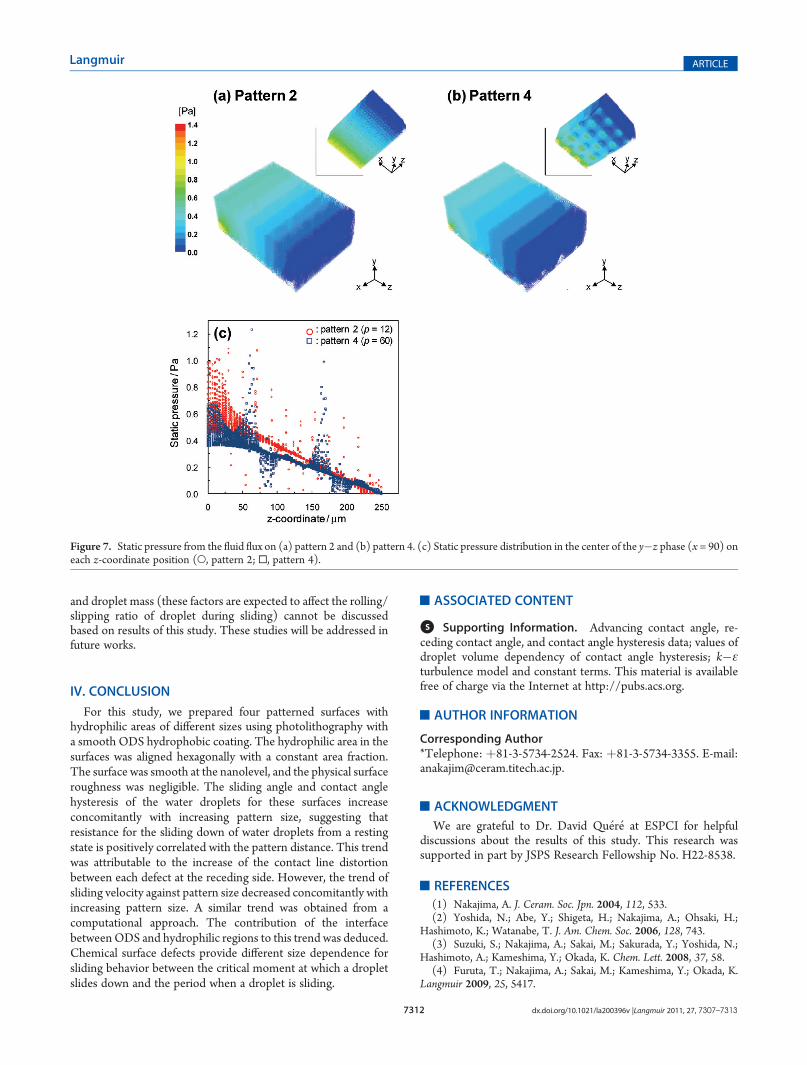
Figure 7a and b portrays simulation results for patterns 2and 4. The color change shows the static pressure distribution.The static pressure at the outlet area became almost 0 Pa on eachmodel, suggesting that the surface area except defects sustainedslipping flow. Figure 7c portrays the static pressure distribution atthe center y�z phase with x = 90 (as Figure 6a shows the “plotphase”). The y-axis shows the static pressure, and the x-axisshows the z coordinate position. The entire static pressuredistribution attributable to the fluid flow on pattern 4 is smallerthan that on pattern 2, except for some specific positions aroundthe surface defects (z = 50, 160). Although the model is simpleand ignores the droplet shape, the trend of experimentallyobtained results on sliding velocity was demonstrated qualita-tively from the simulated results. Themoving resistance for waterdroplets during sliding decreases concomitantly with increasingpattern distance.
It is noteworthy that a similar trend of the triple line motionfor the patterned surface is known for the relation between graingrowth and pinning aids in the sintering process of particulatematerials. When pinning aids are added at the same volume ratioto the sample, smaller aids with a larger number are moreeffective to suppress the motion of the grain boundary duringsintering.33�35 This phenomenon can be demonstrated from theequilibrium between the driving force attributable to the curva-ture of each particle and the restraining force. It also suggests theimportance of the interaction at the interface between themoving grain boundary and pinning aids.
This study was conducted for only one type of well-definedchemically patterned coating. Effects of defect shape (e.g., thatincluding a sharp corner), defect structure distribution, tilt angle,
Figure 6. Simulation fields for (a) pattern 2 and (b) pattern 4.
7312 dx.doi.org/10.1021/la200396v |Langmuir 2011, 27, 7307–7313
Langmuir ARTICLE
and droplet mass (these factors are expected to affect the rolling/slipping ratio of droplet during sliding) cannot be discussedbased on results of this study. These studies will be addressed infuture works.
IV. CONCLUSION
For this study, we prepared four patterned surfaces withhydrophilic areas of different sizes using photolithography witha smooth ODS hydrophobic coating. The hydrophilic area in thesurfaces was aligned hexagonally with a constant area fraction.The surface was smooth at the nanolevel, and the physical surfaceroughness was negligible. The sliding angle and contact anglehysteresis of the water droplets for these surfaces increaseconcomitantly with increasing pattern size, suggesting thatresistance for the sliding down of water droplets from a restingstate is positively correlated with the pattern distance. This trendwas attributable to the increase of the contact line distortionbetween each defect at the receding side. However, the trend ofsliding velocity against pattern size decreased concomitantly withincreasing pattern size. A similar trend was obtained from acomputational approach. The contribution of the interfacebetweenODS and hydrophilic regions to this trend was deduced.Chemical surface defects provide different size dependence forsliding behavior between the critical moment at which a dropletslides down and the period when a droplet is sliding.
’ASSOCIATED CONTENT
bS Supporting Information. Advancing contact angle, re-ceding contact angle, and contact angle hysteresis data; values ofdroplet volume dependency of contact angle hysteresis; k�εturbulence model and constant terms. This material is availablefree of charge via the Internet at http://pubs.acs.org.
’AUTHOR INFORMATION
Corresponding Author*Telephone: þ81-3-5734-2524. Fax: þ81-3-5734-3355. E-mail:[email protected].
’ACKNOWLEDGMENT
We are grateful to Dr. David Qu�er�e at ESPCI for helpfuldiscussions about the results of this study. This research wassupported in part by JSPS Research Fellowship No. H22-8538.
’REFERENCES
(1) Nakajima, A. J. Ceram. Soc. Jpn. 2004, 112, 533.(2) Yoshida, N.; Abe, Y.; Shigeta, H.; Nakajima, A.; Ohsaki, H.;
Hashimoto, K.; Watanabe, T. J. Am. Chem. Soc. 2006, 128, 743.(3) Suzuki, S.; Nakajima, A.; Sakai, M.; Sakurada, Y.; Yoshida, N.;
Hashimoto, A.; Kameshima, Y.; Okada, K. Chem. Lett. 2008, 37, 58.(4) Furuta, T.; Nakajima, A.; Sakai, M.; Kameshima, Y.; Okada, K.
Langmuir 2009, 25, 5417.
Figure 7. Static pressure from the fluid flux on (a) pattern 2 and (b) pattern 4. (c) Static pressure distribution in the center of the y�z phase (x = 90) oneach z-coordinate position (O, pattern 2; 0, pattern 4).
7313 dx.doi.org/10.1021/la200396v |Langmuir 2011, 27, 7307–7313
Langmuir ARTICLE
(5) Dettre, R. H.; Johnson, R. E. In Contact angle, Wettability andAdhesion; Fowkes, F. M., Ed.; Advances in Chemistry Series; AmericanChemical Society: Washington, DC, 1964; Vol. 43, pp 136�144.(6) Qu�er�e, D. Rep. Prog. Phys. 2005, 68, 2495.(7) Johnson, R. E., Jr.; Dettre, R. H. In Surface and Colloid Science;
Matijevi, E., Ed.; Wiley: New York, 1969; Vol. 2, pp 85�153.(8) Decker, E. L.; Garoff, S. Langmuir 1997, 13, 6321.(9) Youngblood, J. P.; MacCarthy, T. J. Macromolecules 1999,
32, 6800.(10) Yoshimitsu, Z.; Nakajima, A.; Watanabe, T.; Hashimoto, K.
Langmuir 2002, 18, 5818.(11) Reyssat, M.; Qu�er�e, D. J. Phys. Chem. B 2009, 113, 3906.(12) €Oner, D.; McCarthy, T. J. Langmuir 2000, 16, 7777.(13) Cubaud, T.; Fermigier, M. J. Colloid Interface Sci. 2004,
269, 171.(14) Iliev, S. D.; Pesheva, N. C. Langmuir 2003, 19, 9923.(15) Ramos, S. M. M.; Charlaix, E.; Benyagoub, A. Surf. Sci. 2003,
540, 355.(16) Buehrle, J.; Herminghaus, S.; Mugele, F. Langmuir 2002,
18, 9771.(17) Kusumaatmaja, H.; Leopoldes, J.; Dupuis, A.; Yeomans, J. M.
Europhys. Lett. 2006, 73, 740.(18) Dussan, E. B.; Chow, R. T. P. J. Fluid Mech. 1983, 137, 1.(19) Lv, C.; Yang, C.; Hao, P.; He, F.; Zheng, Q. Langmuir 2010,
26, 8704.(20) Sugimura, H.; Ushiyama, K.; Hozumi, A.; Takai, O. Langmuir
2000, 16, 885.(21) Koga, T.; Morita, M.; Ishida, H.; Yakabe, H.; Sasaki, S.; Sakata,
O.; Otsuka, H.; Takahara, A. Langmuir 2005, 21, 905.(22) Morita, M.; Koga, T.; Otsuka, H.; Takahara, A. Langmuir 2005,
21, 911.(23) Suzuki, S.; Nakajima, A.; Tanaka, K.; Sakai, M.; Hashimoto, A.;
Yoshida, N.; Kameshima, Y.; Okada, K. Appl. Surf. Sci. 2008, 254, 1797.(24) Cassie, A. B. D. Discuss. Faraday Soc. 1948, 3, 11.(25) Extrand, C. W. Langmuir 2003, 19, 3793.(26) Gao, L.; McCarthy, T. J. Langmuir 2007, 23, 3762.(27) Furmidge, C. G. L. J. Colloid Sci. 1962, 17, 309.(28) Sakai, M.; Song, J.-H.; Yoshida, N.; Suzuki, S.; Kameshima, Y.;
Nakajima, A. Langmuir 2006, 22, 4906.(29) Gogte, S.; Vorobieff, P.; Truesdell, R.; Mammoli, A.; van Swol,
F.; Shah, P.; Brinker, C. J. Phys. Fluids 2005, 17, 51701-1.(30) Hodges, S. R.; Jensen, O. E.; Rallison, J. M. J. Fluid Mech. 2004,
512, 95.(31) Tretheway, D. C.; Meinhart, C. D. Phys. Fluids 2002, 14, L9.(32) Launder, B. E.; Spalding, D. B. Lectures in Mathematical Models
of Turbulence; Academic Press: London, 1972; pp 90�110.(33) Burke, J. E.; Rosolowski, J. H. Reactivity of Solids; Hannay, N. B.,
Ed.; Treatise on Solid State Chemistry; Plenum:NewYork, 1976; Vol. 4,pp 621�659.(34) Kingery, W. D.; Bowen, H. K.; Uhlmann, D. R. Introduction to
Ceramics; Wiley: New York, 1976; pp 449�515.(35) Reed, J. S. Introduction to the Principles of Ceramic Processing;
Wiley: New York, 1988; pp 440�474.