Embed Size (px)
Citation preview
Presenters:Slides 1 thru ‐ 39 ‐ Harold AD7QJSlides 40 thru ‐ 49 ‐Mike KD7GHZ
11/12/2013 Jack Tiley AD7FO, Harold Hepner AD7QJ, Mike Carey KD7GHZ 1
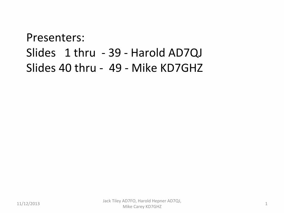
VHF Club November Meeting Presentation
HF Antennas for Portable Operation
11/12/2013 Jack Tiley AD7FO, Harold Hepner AD7QJ, Mike Carey KD7GHZ 2
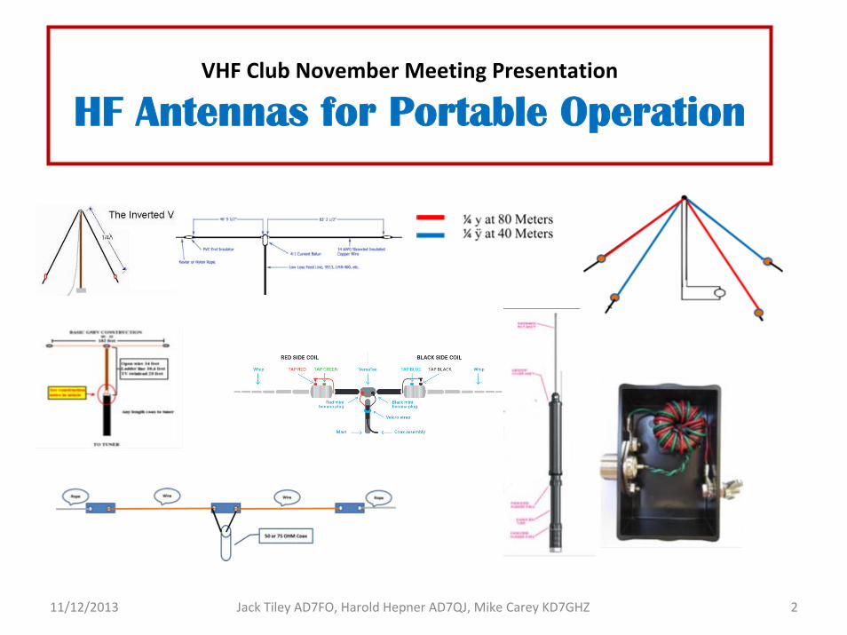
Basic Long Wire
Long wire can be any long wire or metal object:Insulated or un‐insulated wire
Electric Fence (turned off)Un – grounded drain spout and Gutters
Antenna Tuner Required with internal or external Balun (9:1)
3
Antenna TunerTransceiver
To Ground
Long wire > one wave length
11/12/2013 Jack Tiley AD7FO, Harold Hepner AD7QJ, Mike Carey KD7GHZ
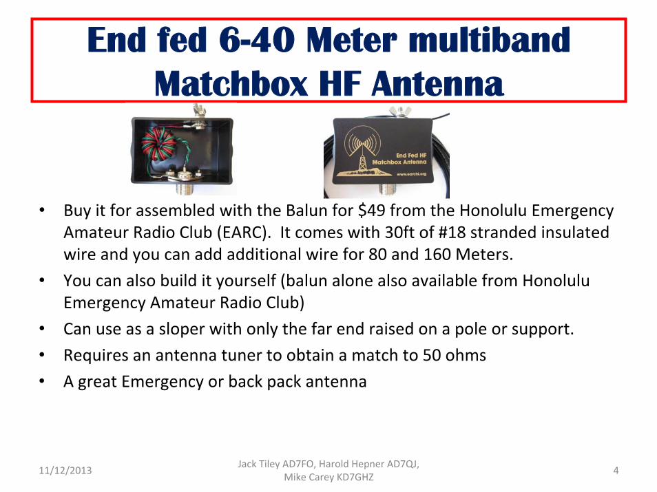
End fed 6-40 Meter multiband Matchbox HF Antenna
• Buy it for assembled with the Balun for $49 from the Honolulu Emergency Amateur Radio Club (EARC). It comes with 30ft of #18 stranded insulated wire and you can add additional wire for 80 and 160 Meters.
• You can also build it yourself (balun alone also available from Honolulu Emergency Amateur Radio Club)
• Can use as a sloper with only the far end raised on a pole or support.• Requires an antenna tuner to obtain a match to 50 ohms • A great Emergency or back pack antenna
411/12/2013 Jack Tiley AD7FO, Harold Hepner AD7QJ, Mike Carey KD7GHZ
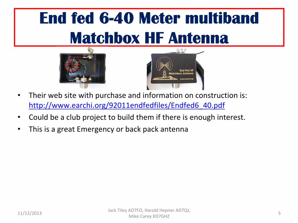
End fed 6-40 Meter multiband Matchbox HF Antenna
• Their web site with purchase and information on construction is:http://www.earchi.org/92011endfedfiles/Endfed6_40.pdf
• Could be a club project to build them if there is enough interest. • This is a great Emergency or back pack antenna
511/12/2013 Jack Tiley AD7FO, Harold Hepner AD7QJ, Mike Carey KD7GHZ
insulator
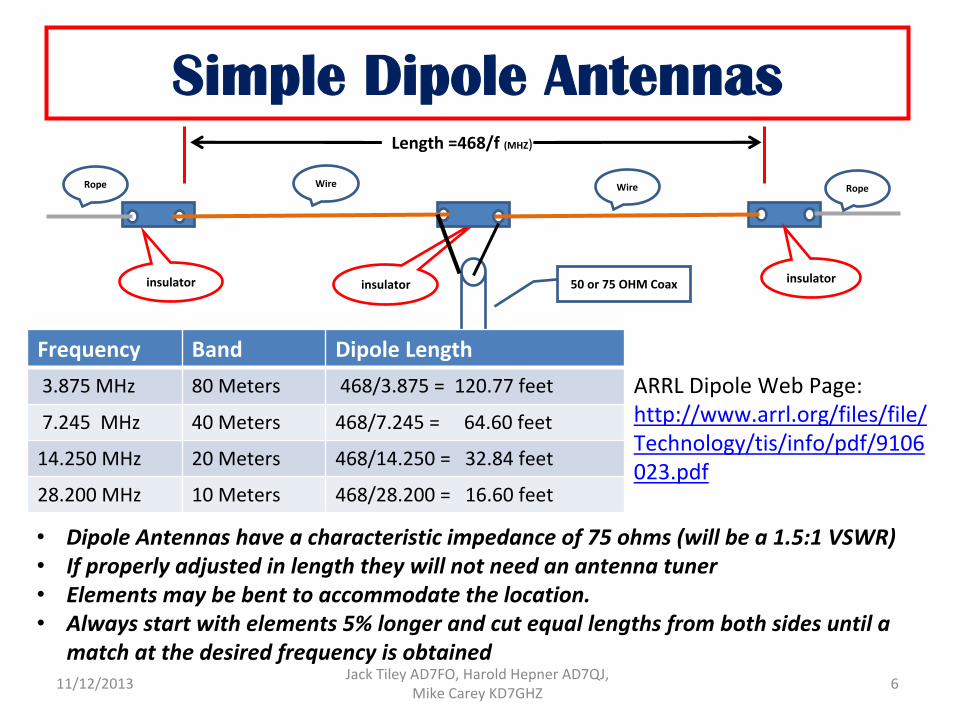
Simple Dipole Antennas
Rope Wire RopeWire
50 or 75 OHM Coax
Length =468/f (MHZ)
Frequency Band Dipole Length 3.875 MHz 80 Meters 468/3.875 = 120.77 feet
7.245 MHz 40 Meters 468/7.245 = 64.60 feet
14.250 MHz 20 Meters 468/14.250 = 32.84 feet
28.200 MHz 10 Meters 468/28.200 = 16.60 feet
insulator insulator
• Dipole Antennas have a characteristic impedance of 75 ohms (will be a 1.5:1 VSWR)• If properly adjusted in length they will not need an antenna tuner • Elements may be bent to accommodate the location. • Always start with elements 5% longer and cut equal lengths from both sides until a
match at the desired frequency is obtained
ARRL Dipole Web Page: http://www.arrl.org/files/file/Technology/tis/info/pdf/9106023.pdf
611/12/2013 Jack Tiley AD7FO, Harold Hepner AD7QJ, Mike Carey KD7GHZ
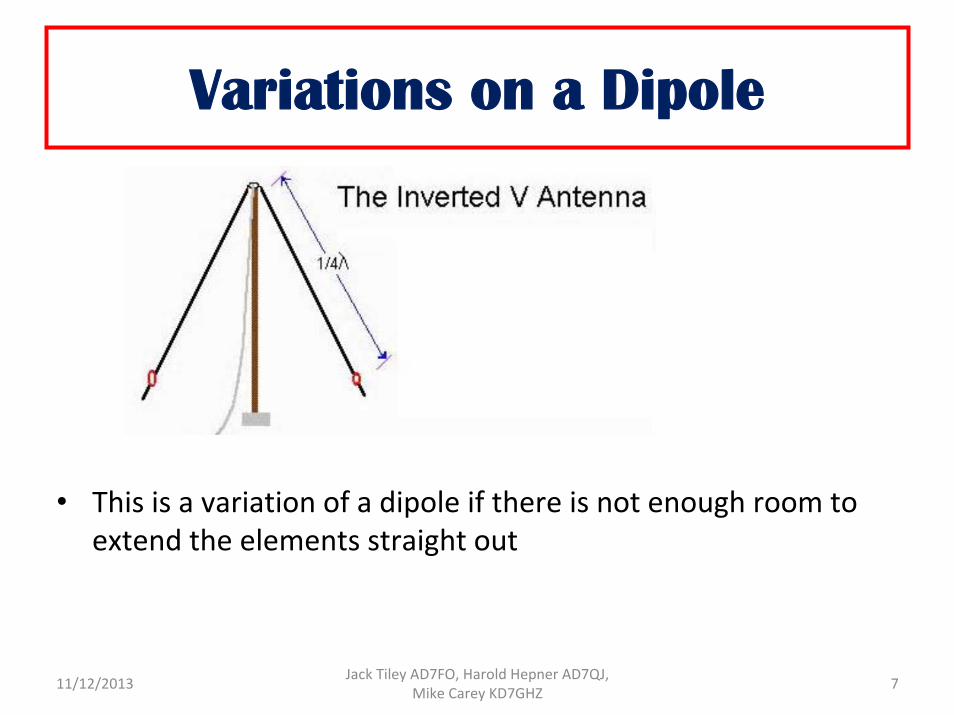
Variations on a Dipole
• This is a variation of a dipole if there is not enough room to extend the elements straight out
711/12/2013 Jack Tiley AD7FO, Harold Hepner AD7QJ, Mike Carey KD7GHZ
Off Center fed Dipole
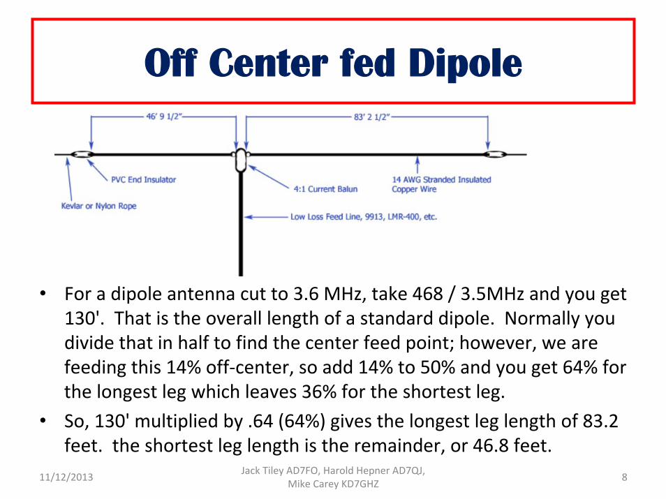
• For a dipole antenna cut to 3.6 MHz, take 468 / 3.5MHz and you get 130'. That is the overall length of a standard dipole. Normally you divide that in half to find the center feed point; however, we are feeding this 14% off‐center, so add 14% to 50% and you get 64% for the longest leg which leaves 36% for the shortest leg.
• So, 130' multiplied by .64 (64%) gives the longest leg length of 83.2 feet. the shortest leg length is the remainder, or 46.8 feet.
811/12/2013 Jack Tiley AD7FO, Harold Hepner AD7QJ, Mike Carey KD7GHZ
Off Center fed Dipole
• To calculate in the velocity factor for 12 or 14 AWG stranded copper, jacketed wire simply take the lengths and multiply them by .975 and you will get the "RF length" of your wire. (This is the real length you require for resonance)
• To build a working version of this Off‐Center Fed Dipole, you will need to buy or build a 4:1 current balun, obtain a couple of end insulators and procure 132 ft of 14AWG jacketed stranded copper wire.
• Cut the 132' of wire to 84' 2 1/2" and strip back about 6" off of one end, each wire to make your balun connection and solder it.
• Measure from the far end of the wire back 6" mark that spot. This is the end of the wire where it passes through the insulator. You have a 6" tail to fold back, strip and solder to form the end of your antenna element.
• This has been calculated using 14 AWG stranded copper wire, with the jacket on. Do not use bare copper wire, or solid copper wire or you will not obtain the same results.
911/12/2013 Jack Tiley AD7FO, Harold Hepner AD7QJ, Mike Carey KD7GHZ
Off Center fed Dipole
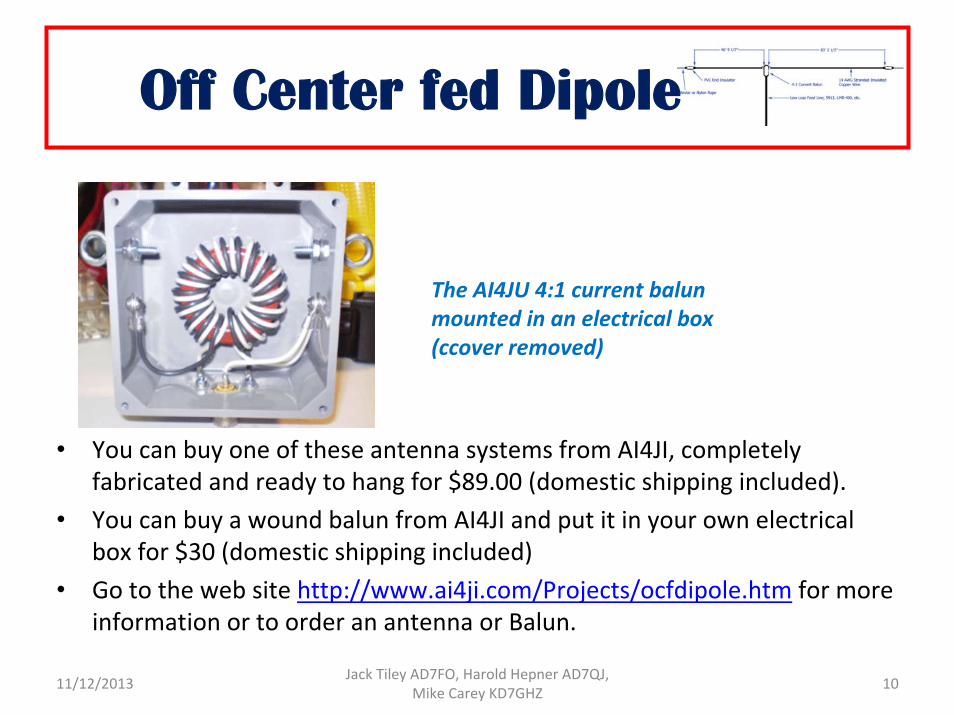
• You can buy one of these antenna systems from AI4JI, completely fabricated and ready to hang for $89.00 (domestic shipping included).
• You can buy a wound balun from AI4JI and put it in your own electrical box for $30 (domestic shipping included)
• Go to the web site http://www.ai4ji.com/Projects/ocfdipole.htm for more information or to order an antenna or Balun.
10
The AI4JU 4:1 current balun mounted in an electrical box (ccover removed)
11/12/2013 Jack Tiley AD7FO, Harold Hepner AD7QJ, Mike Carey KD7GHZ
Off-Center Fed Dipoles
Practical ApplicationsFrom the work of N1IW
11/12/2013 Jack Tiley AD7FO, Harold Hepner AD7QJ, Mike Carey KD7GHZ 11
• Looking for solutions for low band antennas• Was abused by a counterpoise as a child• Looking for multiband solutions• Traditional low band wire arrays use dipoles or inverted vees
• Applications to driven & parasitic arrays
Why?
11/12/2013 Jack Tiley AD7FO, Harold Hepner AD7QJ, Mike Carey KD7GHZ 12
Off Center Fed Dipole Basics
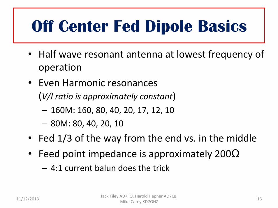
• Half wave resonant antenna at lowest frequency of operation
• Even Harmonic resonances(V/I ratio is approximately constant)– 160M: 160, 80, 40, 20, 17, 12, 10– 80M: 80, 40, 20, 10
• Fed 1/3 of the way from the end vs. in the middle• Feed point impedance is approximately 200Ω
– 4:1 current balun does the trick
11/12/2013 Jack Tiley AD7FO, Harold Hepner AD7QJ, Mike Carey KD7GHZ 13
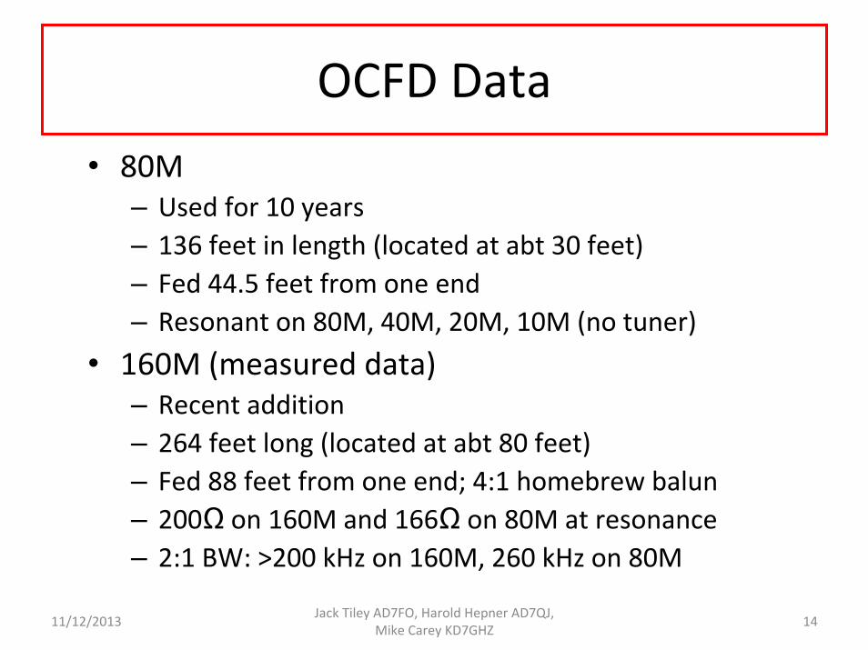
OCFD Data• 80M
– Used for 10 years– 136 feet in length (located at abt 30 feet)– Fed 44.5 feet from one end– Resonant on 80M, 40M, 20M, 10M (no tuner)
• 160M (measured data)– Recent addition– 264 feet long (located at abt 80 feet)– Fed 88 feet from one end; 4:1 homebrew balun– 200Ω on 160M and 166Ω on 80M at resonance– 2:1 BW: >200 kHz on 160M, 260 kHz on 80M
11/12/2013 Jack Tiley AD7FO, Harold Hepner AD7QJ, Mike Carey KD7GHZ 14
Why They Work
• It’s just a dipole!
• But– ½ wave resonant element, then harmonic wire– Voltage/Current relationship at 1/3 feed point provides essentially constant ratio on even harmonics
– Broadside null on harmonics
11/12/2013 Jack Tiley AD7FO, Harold Hepner AD7QJ, Mike Carey KD7GHZ 15
Current Distribution on a Dipole
11/12/2013 Jack Tiley AD7FO, Harold Hepner AD7QJ, Mike Carey KD7GHZ 16
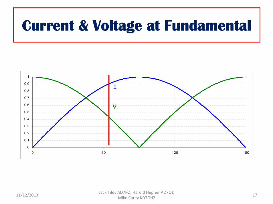
Current & Voltage at Fundamental
0
0.1
0.2
0.3
0.4
0.5
0.6
0.7
0.8
0.9
1
0 60 120 180
V
I
11/12/2013 Jack Tiley AD7FO, Harold Hepner AD7QJ, Mike Carey KD7GHZ 17
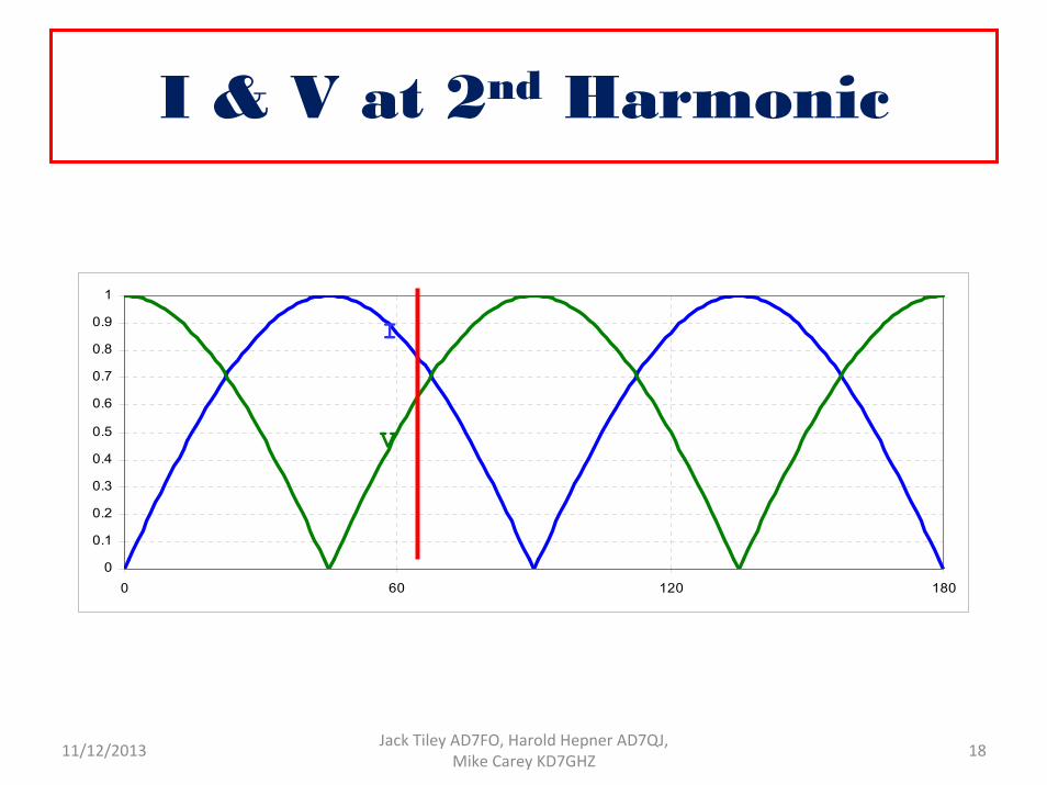
I & V at 2nd Harmonic
0
0.1
0.2
0.3
0.4
0.5
0.6
0.7
0.8
0.9
1
0 60 120 180
I
V
11/12/2013 Jack Tiley AD7FO, Harold Hepner AD7QJ, Mike Carey KD7GHZ 18
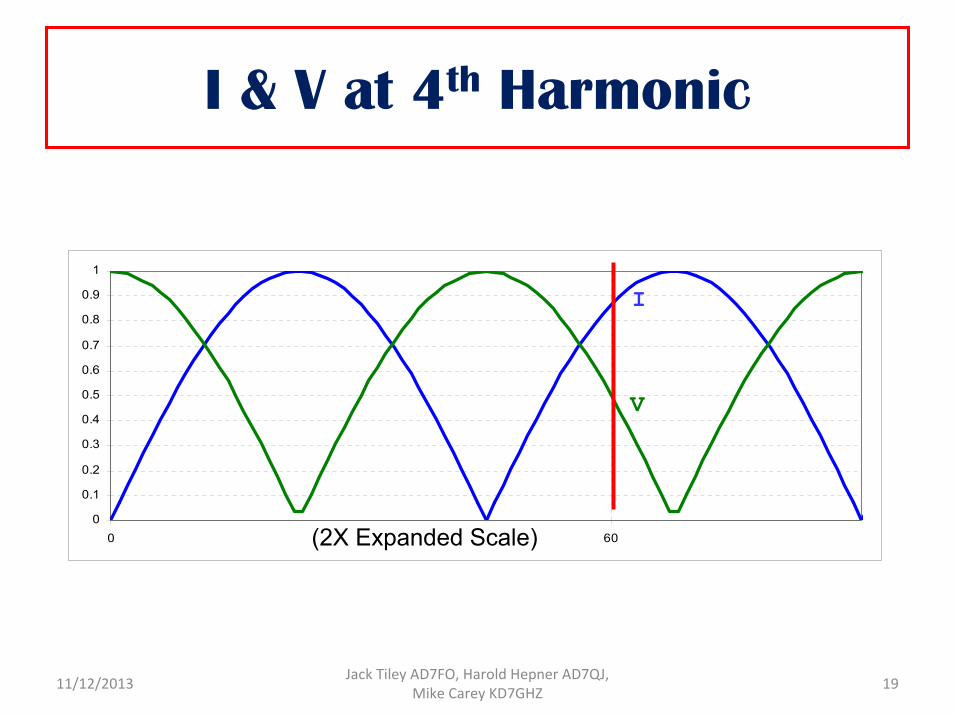
I & V at 4th Harmonic
0
0.1
0.2
0.3
0.4
0.5
0.6
0.7
0.8
0.9
1
0 60
I
V
(2X Expanded Scale)
11/12/2013 Jack Tiley AD7FO, Harold Hepner AD7QJ, Mike Carey KD7GHZ 19
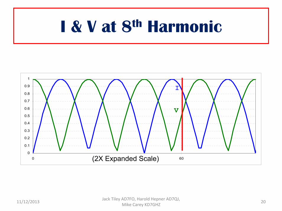
I & V at 8th Harmonic
0
0.1
0.2
0.3
0.4
0.5
0.6
0.7
0.8
0.9
1
0 60
I
V
(2X Expanded Scale)
11/12/2013 Jack Tiley AD7FO, Harold Hepner AD7QJ, Mike Carey KD7GHZ 20
But what about the 6th harmonic?
• Feed point is at a current minimum
• Very high impedance
11/12/2013 Jack Tiley AD7FO, Harold Hepner AD7QJ, Mike Carey KD7GHZ 21
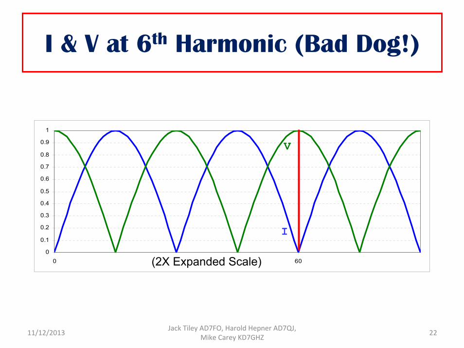
I & V at 6th Harmonic (Bad Dog!)
0
0.1
0.2
0.3
0.4
0.5
0.6
0.7
0.8
0.9
1
0 60
I
V
(2X Expanded Scale)
11/12/2013 Jack Tiley AD7FO, Harold Hepner AD7QJ, Mike Carey KD7GHZ 22
And Odd Harmonics?
• Same problem: Current minimum
11/12/2013 Jack Tiley AD7FO, Harold Hepner AD7QJ, Mike Carey KD7GHZ 23
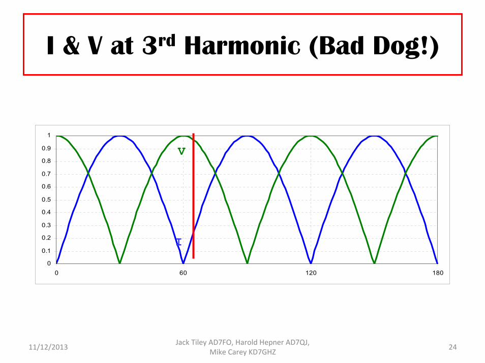
I & V at 3rd Harmonic (Bad Dog!)
0
0.1
0.2
0.3
0.4
0.5
0.6
0.7
0.8
0.9
1
0 60 120 180
I
V
11/12/2013 Jack Tiley AD7FO, Harold Hepner AD7QJ, Mike Carey KD7GHZ 24
Basic Gain Plots
11/12/2013 Jack Tiley AD7FO, Harold Hepner AD7QJ, Mike Carey KD7GHZ 25
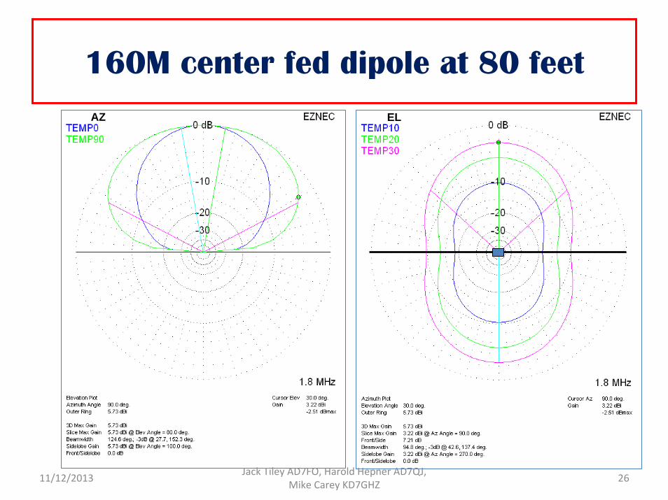
160M center fed dipole at 80 feetELAZ
11/12/2013 Jack Tiley AD7FO, Harold Hepner AD7QJ, Mike Carey KD7GHZ 26
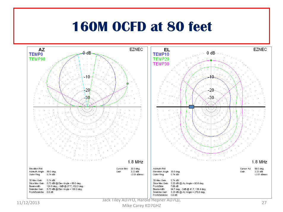
160M OCFD at 80 feetAZ EL
11/12/2013 Jack Tiley AD7FO, Harold Hepner AD7QJ, Mike Carey KD7GHZ 27
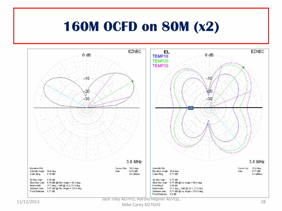
160M OCFD on 80M (x2)
EL
11/12/2013 Jack Tiley AD7FO, Harold Hepner AD7QJ, Mike Carey KD7GHZ 28
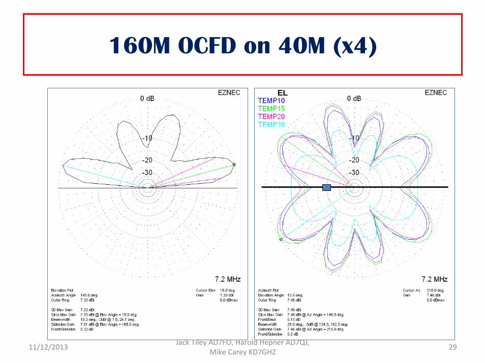
160M OCFD on 40M (x4)
EL
11/12/2013 Jack Tiley AD7FO, Harold Hepner AD7QJ, Mike Carey KD7GHZ 29
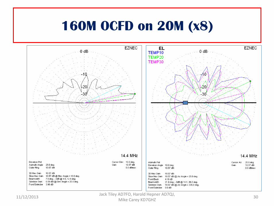
160M OCFD on 20M (x8)EL
11/12/2013 Jack Tiley AD7FO, Harold Hepner AD7QJ, Mike Carey KD7GHZ 30
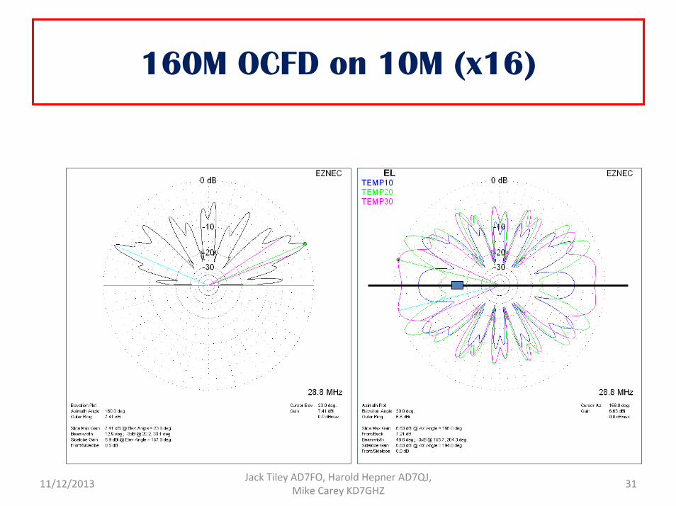
160M OCFD on 10M (x16)
EL
11/12/2013 Jack Tiley AD7FO, Harold Hepner AD7QJ, Mike Carey KD7GHZ 31
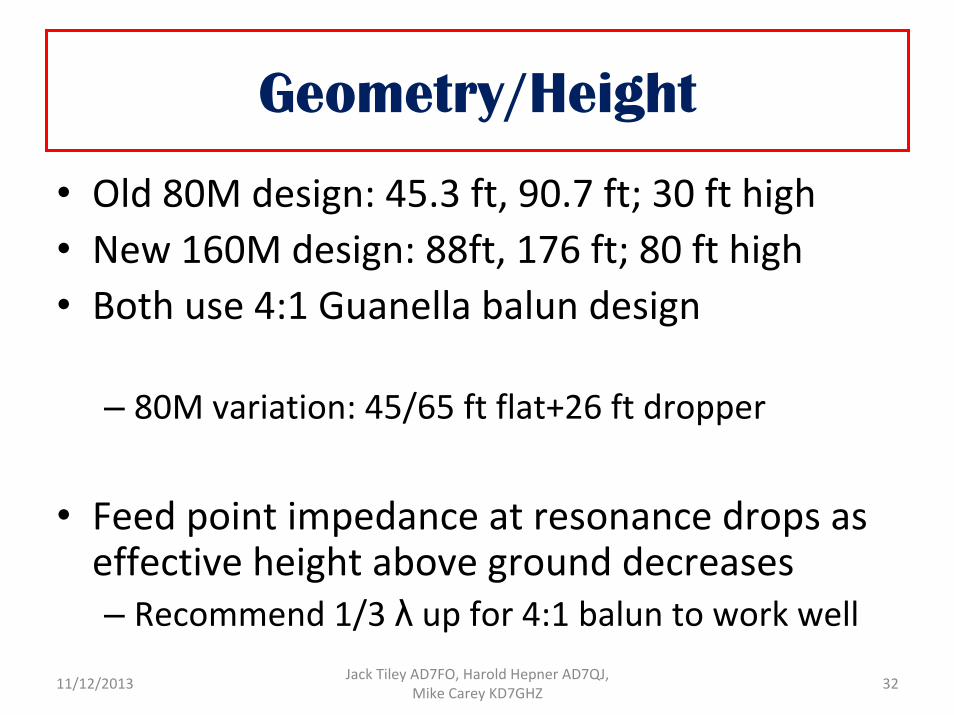
Geometry/Height
• Old 80M design: 45.3 ft, 90.7 ft; 30 ft high• New 160M design: 88ft, 176 ft; 80 ft high• Both use 4:1 Guanella balun design
– 80M variation: 45/65 ft flat+26 ft dropper
• Feed point impedance at resonance drops as effective height above ground decreases– Recommend 1/3 λ up for 4:1 balun to work well
11/12/2013 Jack Tiley AD7FO, Harold Hepner AD7QJ, Mike Carey KD7GHZ 32
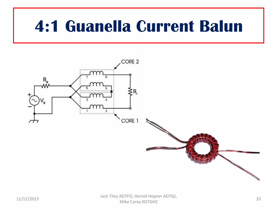
4:1 Guanella Current Balun
11/12/2013 Jack Tiley AD7FO, Harold Hepner AD7QJ, Mike Carey KD7GHZ 33
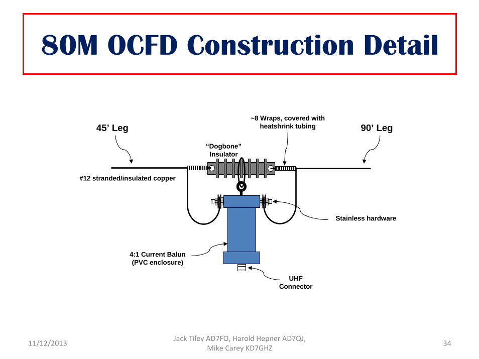
90’ Leg45’ Leg
#12 stranded/insulated copper
4:1 Current Balun(PVC enclosure)
~8 Wraps, covered with heatshrink tubing
“Dogbone”Insulator
UHF Connector
Stainless hardware
80M OCFD Construction Detail
11/12/2013 Jack Tiley AD7FO, Harold Hepner AD7QJ, Mike Carey KD7GHZ 34

176’ Leg88’ Leg
#12 stranded/insulated copper
4:1 Current Balun(PVC enclosure)
~8 Wraps, covered with heatshrink tubing
“Dogbone”Insulator
UHF Connector
Stainless hardware
160M OCFD Construction Detail
11/12/2013 Jack Tiley AD7FO, Harold Hepner AD7QJ, Mike Carey KD7GHZ 35
OCFD Orientation Issues
11/12/2013 Jack Tiley AD7FO, Harold Hepner AD7QJ, Mike Carey KD7GHZ 36
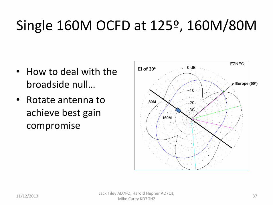
Single 160M OCFD at 125º, 160M/80M
• How to deal with the broadside null…
• Rotate antenna to achieve best gain compromise
Europe (50º)
80M
160M
El of 30º
11/12/2013 Jack Tiley AD7FO, Harold Hepner AD7QJ, Mike Carey KD7GHZ 37
Disclaimer…
• Your mileage may vary• Batteries not included• Some assembly required• Professional driver, closed course• Void where prohibited• Do not dispose of in fire• Taxes, titles, license fees extra• 10M band openings longer than 2 hours require immediate medical attention
11/12/2013 Jack Tiley AD7FO, Harold Hepner AD7QJ, Mike Carey KD7GHZ 38
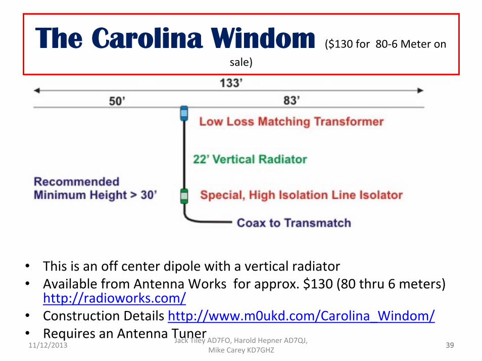
The Carolina Windom ($130 for 80‐6 Meter on sale)
• This is an off center dipole with a vertical radiator• Available from Antenna Works for approx. $130 (80 thru 6 meters)
http://radioworks.com/• Construction Details http://www.m0ukd.com/Carolina_Windom/• Requires an Antenna Tuner
3911/12/2013 Jack Tiley AD7FO, Harold Hepner AD7QJ, Mike Carey KD7GHZ 39
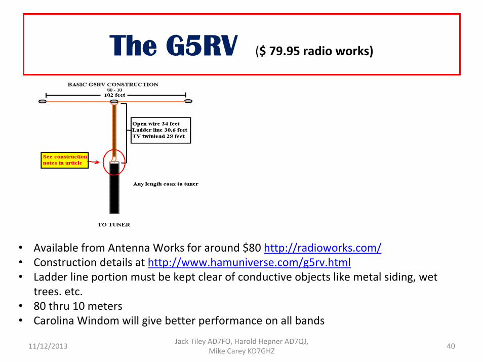
The G5RV ($ 79.95 radio works)
• Available from Antenna Works for around $80 http://radioworks.com/• Construction details at http://www.hamuniverse.com/g5rv.html• Ladder line portion must be kept clear of conductive objects like metal siding, wet
trees. etc. • 80 thru 10 meters • Carolina Windom will give better performance on all bands
4011/12/2013 Jack Tiley AD7FO, Harold Hepner AD7QJ, Mike Carey KD7GHZ
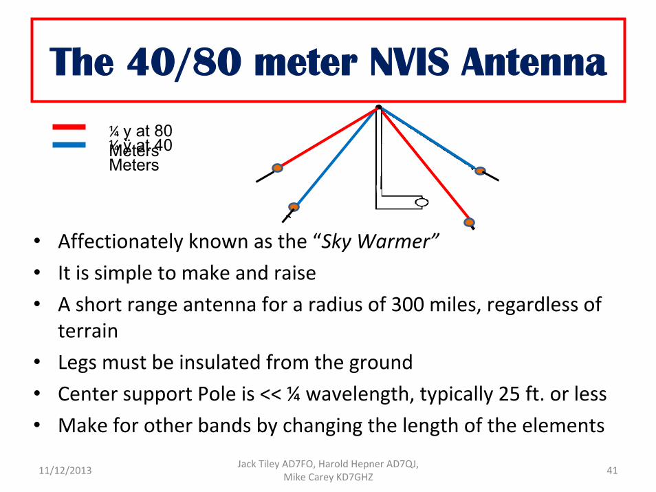
¼ ÿ at 80 Meters¼ ÿ at 40 Meters
The 40/80 meter NVIS Antenna
• Affectionately known as the “Sky Warmer”• It is simple to make and raise• A short range antenna for a radius of 300 miles, regardless of
terrain• Legs must be insulated from the ground • Center support Pole is << ¼ wavelength, typically 25 ft. or less• Make for other bands by changing the length of the elements
4111/12/2013 Jack Tiley AD7FO, Harold Hepner AD7QJ, Mike Carey KD7GHZ
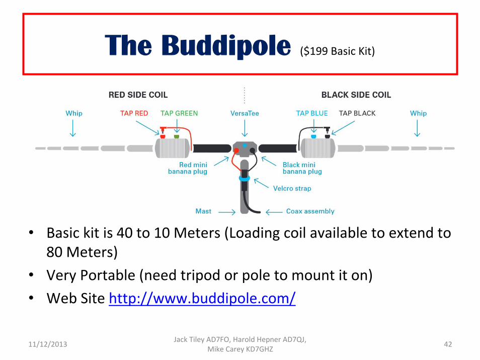
The Buddipole ($199 Basic Kit)
• Basic kit is 40 to 10 Meters (Loading coil available to extend to 80 Meters)
• Very Portable (need tripod or pole to mount it on) • Web Site http://www.buddipole.com/
4211/12/2013 Jack Tiley AD7FO, Harold Hepner AD7QJ, Mike Carey KD7GHZ
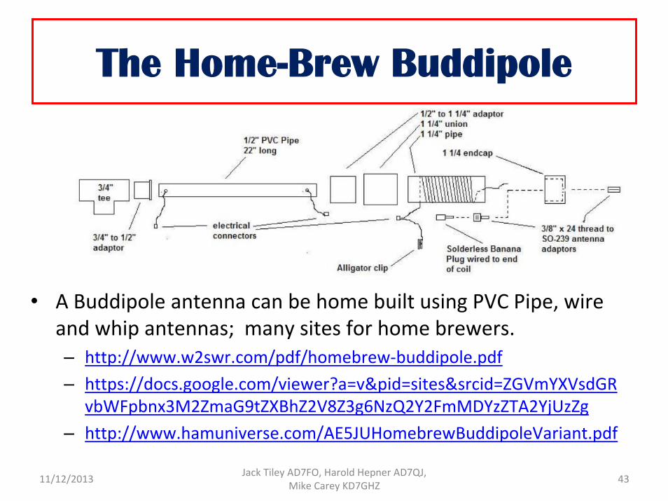
• A Buddipole antenna can be home built using PVC Pipe, wire and whip antennas; many sites for home brewers. – http://www.w2swr.com/pdf/homebrew‐buddipole.pdf– https://docs.google.com/viewer?a=v&pid=sites&srcid=ZGVmYXVsdGR
vbWFpbnx3M2ZmaG9tZXBhZ2V8Z3g6NzQ2Y2FmMDYzZTA2YjUzZg– http://www.hamuniverse.com/AE5JUHomebrewBuddipoleVariant.pdf
The Home-Brew Buddipole
4311/12/2013 Jack Tiley AD7FO, Harold Hepner AD7QJ, Mike Carey KD7GHZ
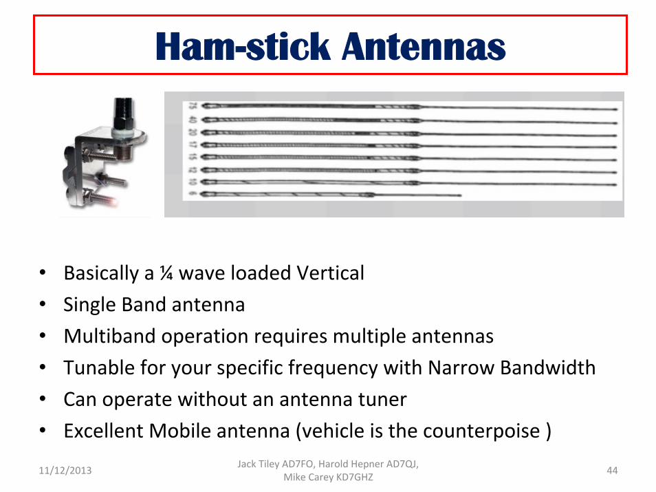
Ham-stick Antennas
• Basically a ¼ wave loaded Vertical • Single Band antenna • Multiband operation requires multiple antennas• Tunable for your specific frequency with Narrow Bandwidth • Can operate without an antenna tuner • Excellent Mobile antenna (vehicle is the counterpoise )
4411/12/2013 Jack Tiley AD7FO, Harold Hepner AD7QJ, Mike Carey KD7GHZ
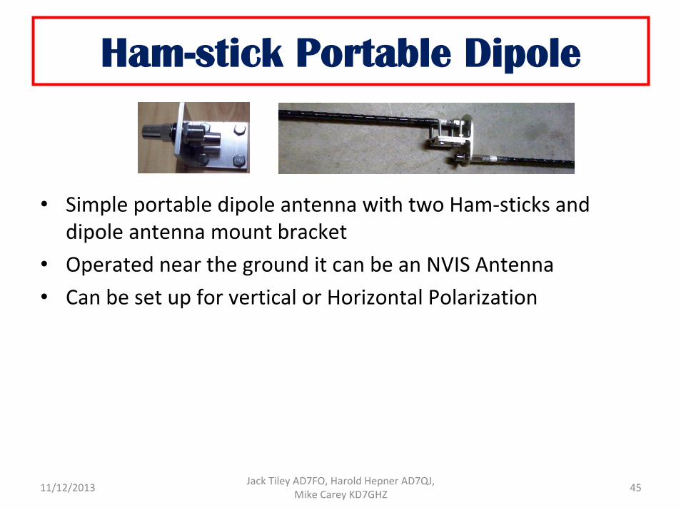
Ham-stick Portable Dipole
• Simple portable dipole antenna with two Ham‐sticks and dipole antenna mount bracket
• Operated near the ground it can be an NVIS Antenna• Can be set up for vertical or Horizontal Polarization
4511/12/2013 Jack Tiley AD7FO, Harold Hepner AD7QJ, Mike Carey KD7GHZ
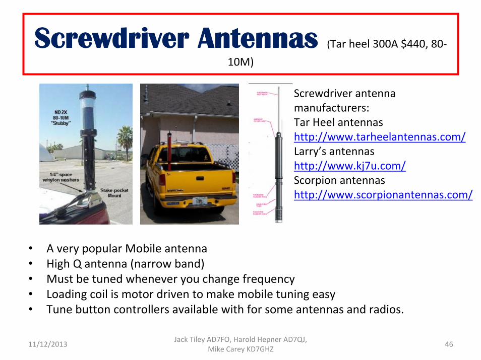
Screwdriver Antennas (Tar heel 300A $440, 80‐10M)
• A very popular Mobile antenna• High Q antenna (narrow band) • Must be tuned whenever you change frequency• Loading coil is motor driven to make mobile tuning easy• Tune button controllers available with for some antennas and radios.
Screwdriver antenna manufacturers:Tar Heel antennas http://www.tarheelantennas.com/Larry’s antennashttp://www.kj7u.com/Scorpion antennas http://www.scorpionantennas.com/
4611/12/2013 Jack Tiley AD7FO, Harold Hepner AD7QJ, Mike Carey KD7GHZ
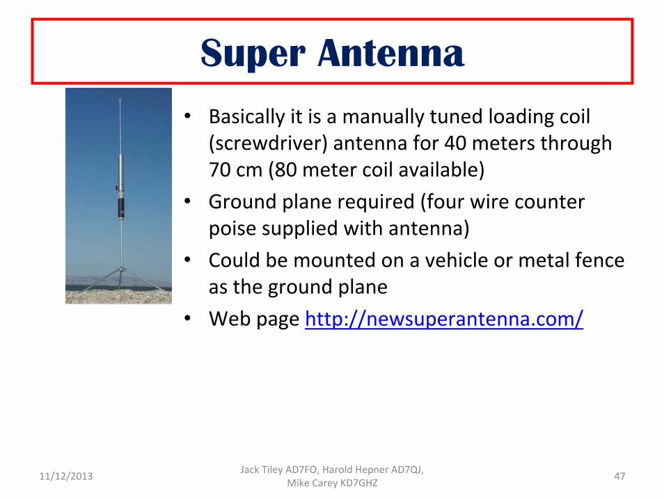
Super Antenna • Basically it is a manually tuned loading coil
(screwdriver) antenna for 40 meters through 70 cm (80 meter coil available)
• Ground plane required (four wire counter poise supplied with antenna)
• Could be mounted on a vehicle or metal fence as the ground plane
• Web page http://newsuperantenna.com/
4711/12/2013 Jack Tiley AD7FO, Harold Hepner AD7QJ, Mike Carey KD7GHZ
The Bottom line
• Portable HF antennas can be simple and inexpensive• They can be electrically loaded (coils added) to reduce the
physical size• Can be used for both portable and fixed operation • Build, borrow or buy one and experiment to see what works
for you then build or buy one for your go kit. • Determine what bands you want to operate on • How far do you want to communicate (local or DX) • Dipoles and long wire antennas are “cheap” and easy to build • Dipoles can be made into multiband antennas with additional insulators and wire
4811/12/2013 Jack Tiley AD7FO, Harold Hepner AD7QJ, Mike Carey KD7GHZ

Lets Experiment, Learn and Have Fun
11/12/2013 Jack Tiley AD7FO, Harold Hepner AD7QJ, Mike Carey KD7GHZ 49

11/12/2013 Jack Tiley AD7FO, Harold Hepner AD7QJ, Mike Carey KD7GHZ 50