Embed Size (px)
Citation preview
Slide 1
Chapter 4
Software Requirements
Slide 2
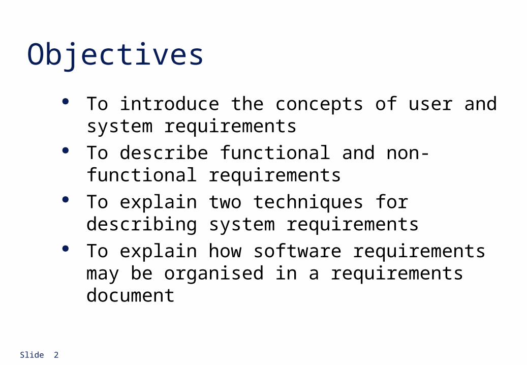
Objectives To introduce the concepts of user and system
requirements To describe functional and non-functional
requirements To explain two techniques for describing system
requirements To explain how software requirements may be
organised in a requirements document
Slide 3
4.1 Requirement It may range from a high-level abstract statement of a
service or of a system constraint to a detailed mathematical functional specification
This is inevitable as requirements may serve a dual function• May be the basis for a bid for a contract - therefore must be open to
interpretation
• May be the basis for the contract itself - therefore must be defined in detail
• Both these statements may be called requirements
Slide 4
Types of requirement User requirements
• Statements in natural language plus diagrams of the services the system provides and its operational constraints. Written for customers
System requirements• A structured document setting out detailed descriptions of the system
services. Written as a contract between client and contractor
Software specification• A detailed software description which can serve as a basis for a design
or implementation. Written for developers
Slide 5
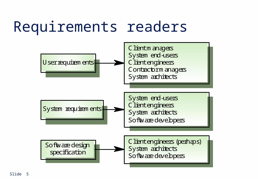
Requirements readersClient managersSystem end-usersClient engineersContractor managersSystem architects
System end-usersClient engineersSystem architectsSoftware developers
Client engineers (perhaps)System architectsSoftware developers
User requirements
System requirements
Software designspecification
Slide 6
4.2. Functional and non-functional requirements
Functional requirements• Statements of services the system should provide, how the system
should react to particular inputs and how the system should behave in particular situations.
Non-functional requirements• constraints on the services or functions offered by the system such as
timing constraints, constraints on the development process, standards, etc.
Domain requirements• Requirements that come from the application domain of the system
and that reflect characteristics of that domain
Slide 7
Functional requirements Describe functionality or system services Depend on the type of software, expected users and
the type of system where the software is used Functional user requirements may be high-level
statements of what the system should do but functional system requirements should describe the system services in detail (input, output, computation, exceptions, etc.)
Slide 8
Example:
Summarize the functional requirements for a software system which allow a user to control a microwave oven .
Slide 9
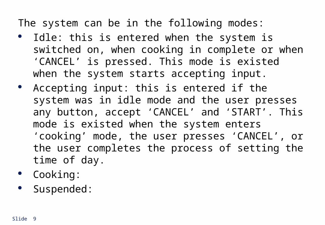
The system can be in the following modes: Idle: this is entered when the system is switched on,
when cooking in complete or when ‘CANCEL’ is pressed. This mode is existed when the system starts accepting input.
Accepting input: this is entered if the system was in idle mode and the user presses any button, accept ‘CANCEL’ and ‘START’. This mode is existed when the system enters ‘cooking’ mode, the user presses ‘CANCEL’, or the user completes the process of setting the time of day.
Cooking: Suspended:
Slide 10
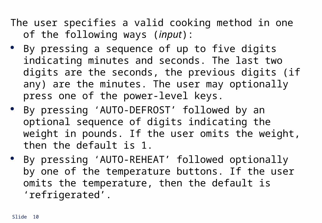
The user specifies a valid cooking method in one of the following ways (input):
By pressing a sequence of up to five digits indicating minutes and seconds. The last two digits are the seconds, the previous digits (if any) are the minutes. The user may optionally press one of the power-level keys.
By pressing ‘AUTO-DEFROST’ followed by an optional sequence of digits indicating the weight in pounds. If the user omits the weight, then the default is 1.
By pressing ‘AUTO-REHEAT’ followed optionally by one of the temperature buttons. If the user omits the temperature, then the default is ‘refrigerated’.
Slide 11
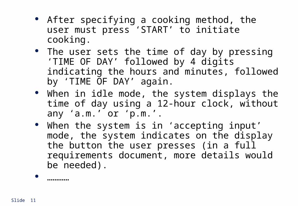
After specifying a cooking method, the user must press ‘START’ to initiate cooking.
The user sets the time of day by pressing ‘TIME OF DAY’ followed by 4 digits indicating the hours and minutes, followed by ‘TIME OF DAY’ again.
When in idle mode, the system displays the time of day using a 12-hour clock, without any ‘a.m.’ or ‘p.m.’.
When the system is in ‘accepting input’ mode, the system indicates on the display the button the user presses (in a full requirements document, more details would be needed).
…………
Slide 12
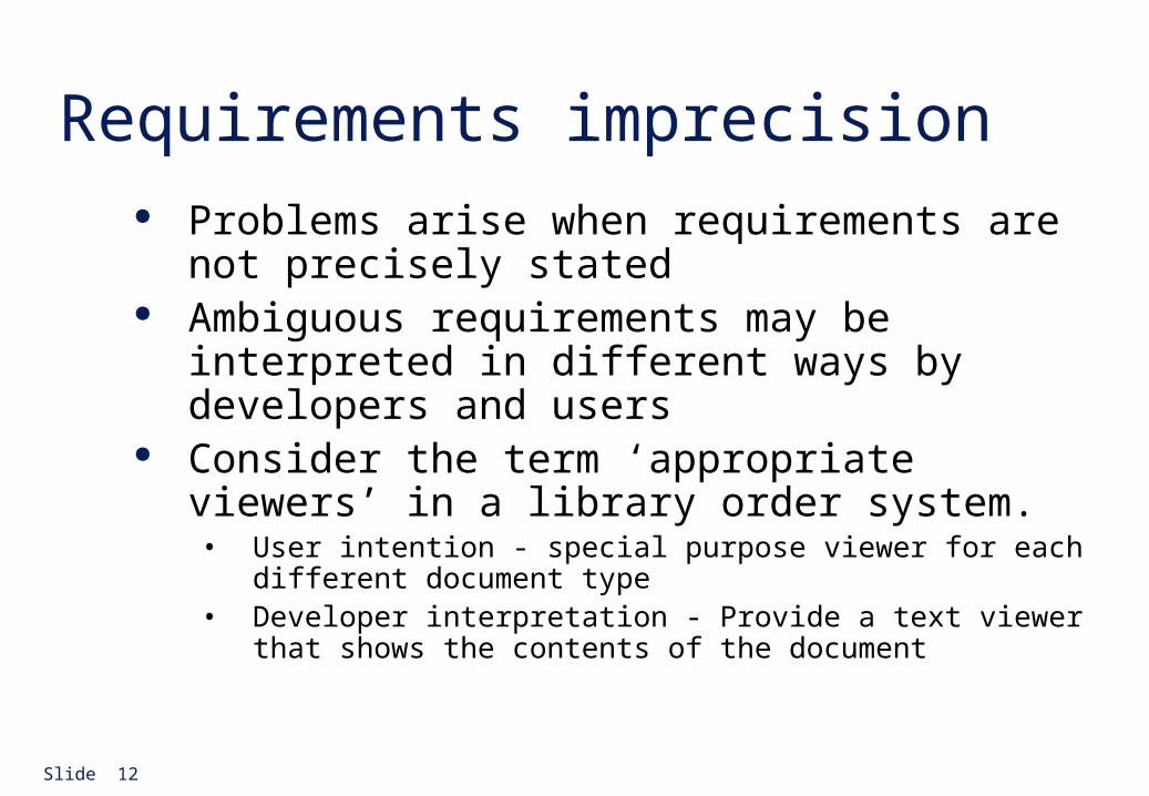
Requirements imprecision Problems arise when requirements are not precisely
stated Ambiguous requirements may be interpreted in
different ways by developers and users Consider the term ‘appropriate viewers’ in a library
order system.• User intention - special purpose viewer for each different document
type• Developer interpretation - Provide a text viewer that shows the
contents of the document
Slide 13
Requirements completeness and consistency
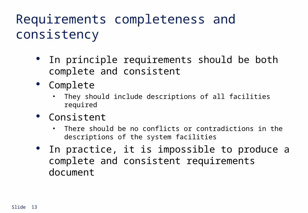
In principle requirements should be both complete and consistent
Complete• They should include descriptions of all facilities required
Consistent• There should be no conflicts or contradictions in the descriptions of
the system facilities
In practice, it is impossible to produce a complete and consistent requirements document
Slide 14
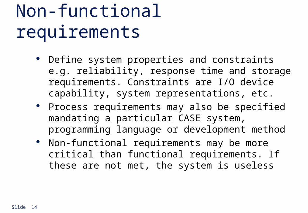
Non-functional requirements Define system properties and constraints e.g. reliability,
response time and storage requirements. Constraints are I/O device capability, system representations, etc.
Process requirements may also be specified mandating a particular CASE system, programming language or development method
Non-functional requirements may be more critical than functional requirements. If these are not met, the system is useless
Slide 15
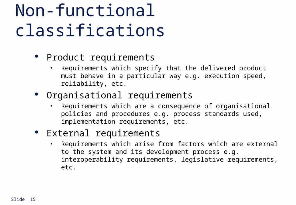
Non-functional classifications Product requirements
• Requirements which specify that the delivered product must behave in a particular way e.g. execution speed, reliability, etc.
Organisational requirements• Requirements which are a consequence of organisational policies and
procedures e.g. process standards used, implementation requirements, etc.
External requirements• Requirements which arise from factors which are external to the
system and its development process e.g. interoperability requirements, legislative requirements, etc.
Slide 16
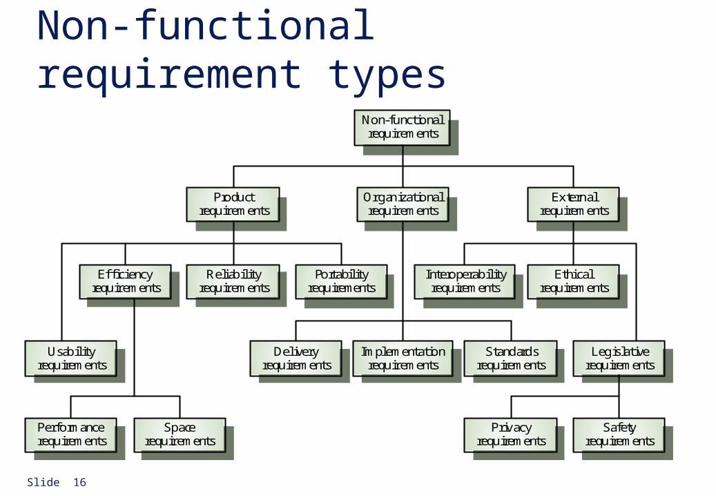
Non-functional requirement types
Performancerequirements
Spacerequirements
Usabilityrequirements
Efficiencyrequirements
Reliabilityrequirements
Portabilityrequirements
Interoperabilityrequirements
Ethicalrequirements
Legislativerequirements
Implementationrequirements
Standardsrequirements
Deliveryrequirements
Safetyrequirements
Privacyrequirements
Productrequirements
Organizationalrequirements
Externalrequirements
Non-functionalrequirements
Slide 17
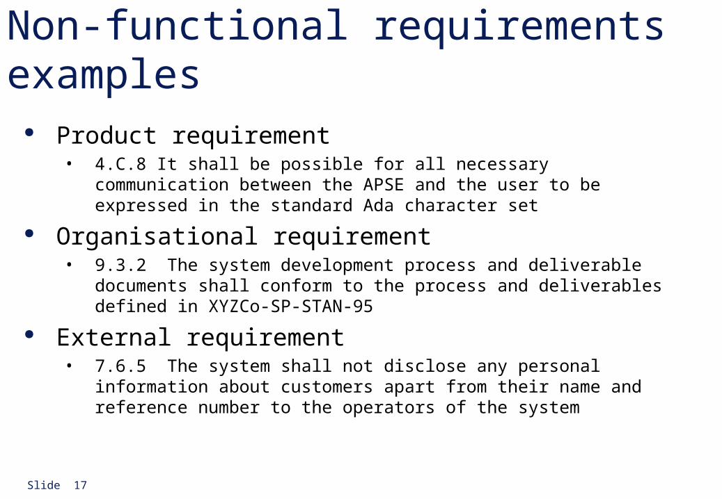
Non-functional requirements examples Product requirement
• 4.C.8 It shall be possible for all necessary communication between the APSE and the user to be expressed in the standard Ada character set
Organisational requirement• 9.3.2 The system development process and deliverable documents shall
conform to the process and deliverables defined in XYZCo-SP-STAN-95
External requirement• 7.6.5 The system shall not disclose any personal information about
customers apart from their name and reference number to the operators of the system
Slide 18
Non-functional requirements problem
Non-functional requirements may be very difficult to state precisely and imprecise requirements may be difficult to verify.
Goal• A general intention of the user such as ease of use
Verifiable non-functional requirement• A statement using some measure that can be objectively tested
Goals are helpful to developers as they convey the intentions of the system users
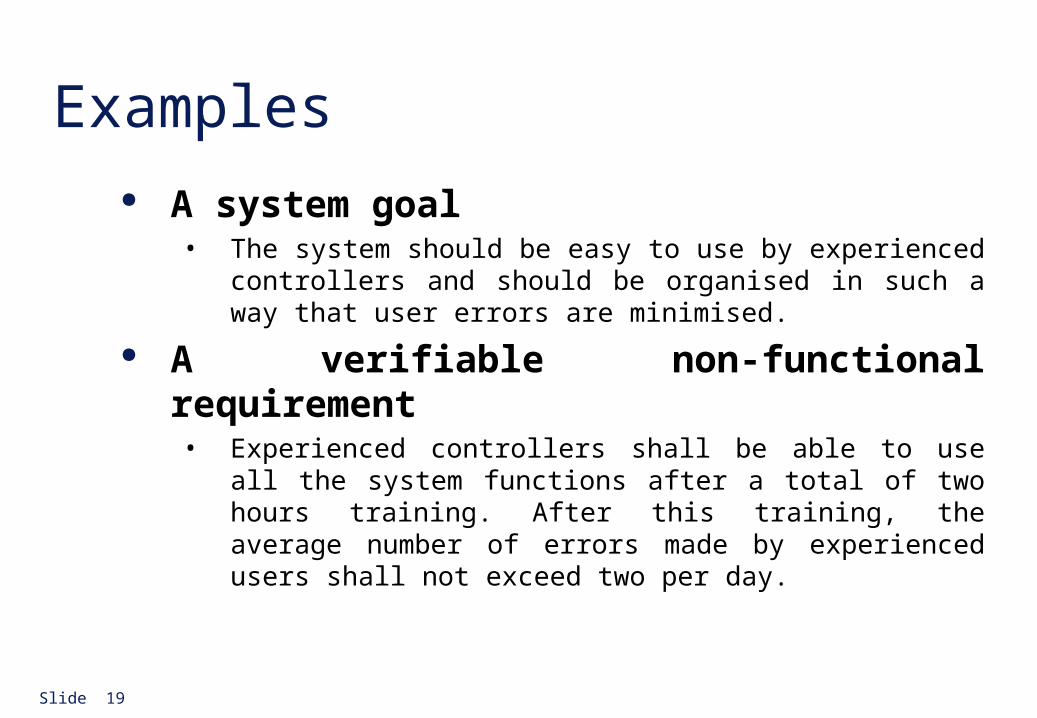
Slide 19
Examples A system goal
• The system should be easy to use by experienced controllers and should be organised in such a way that user errors are minimised.
A verifiable non-functional requirement• Experienced controllers shall be able to use all the system functions
after a total of two hours training. After this training, the average number of errors made by experienced users shall not exceed two per day.
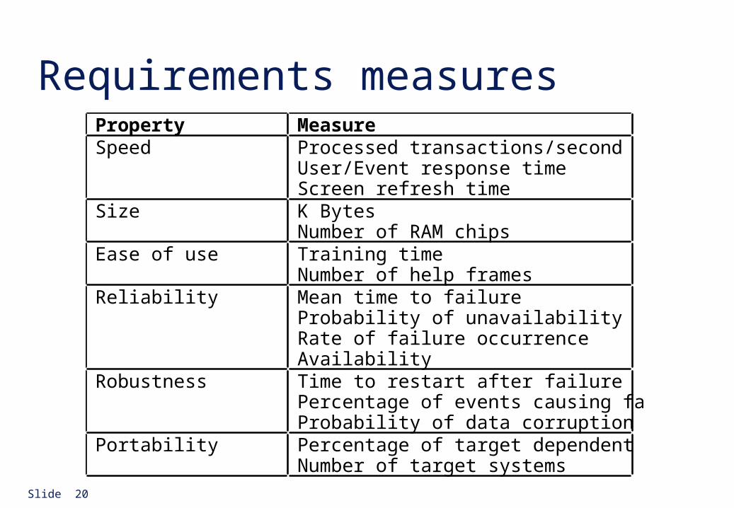
Slide 20
Requirements measuresProperty MeasureSpeed Processed transactions/second
User/Event response timeScreen refresh time
Size K BytesNumber of RAM chips
Ease of use Training timeNumber of help frames
Reliability Mean time to failureProbability of unavailabilityRate of failure occurrenceAvailability
Robustness Time to restart after failurePercentage of events causing failureProbability of data corruption on failure
Portability Percentage of target dependent statementsNumber of target systems
Slide 21
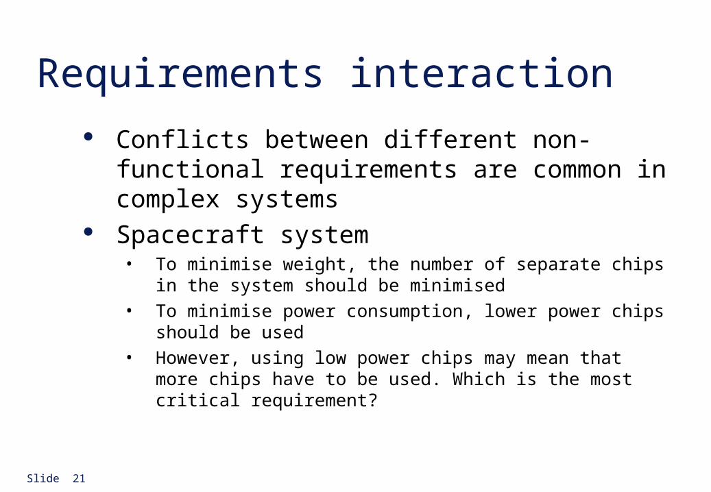
Requirements interaction Conflicts between different non-functional
requirements are common in complex systems Spacecraft system
• To minimise weight, the number of separate chips in the system should be minimised
• To minimise power consumption, lower power chips should be used
• However, using low power chips may mean that more chips have to be used. Which is the most critical requirement?
Slide 22
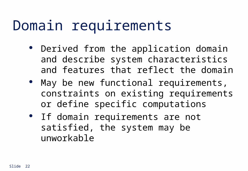
Domain requirements Derived from the application domain and describe
system characteristics and features that reflect the domain
May be new functional requirements, constraints on existing requirements or define specific computations
If domain requirements are not satisfied, the system may be unworkable
Slide 23
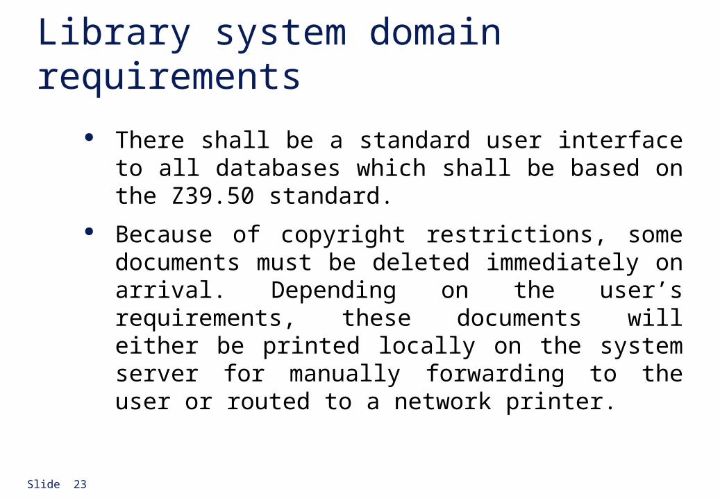
Library system domain requirements
There shall be a standard user interface to all databases which shall be based on the Z39.50 standard.
Because of copyright restrictions, some documents must be deleted immediately on arrival. Depending on the user’s requirements, these documents will either be printed locally on the system server for manually forwarding to the user or routed to a network printer.
Slide 24
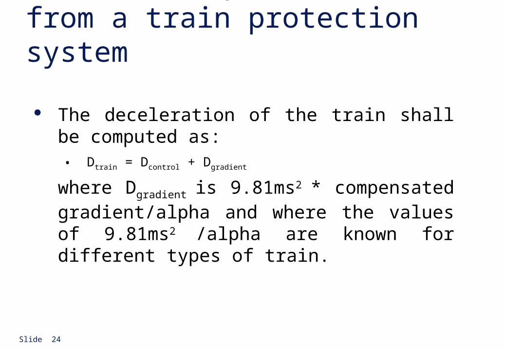
A domain requirement from a train protection system
The deceleration of the train shall be computed as:• Dtrain = Dcontrol + Dgradient
where Dgradient is 9.81ms2 * compensated gradient/alpha and where the values of 9.81ms2 /alpha are known for different types of train.
Slide 25
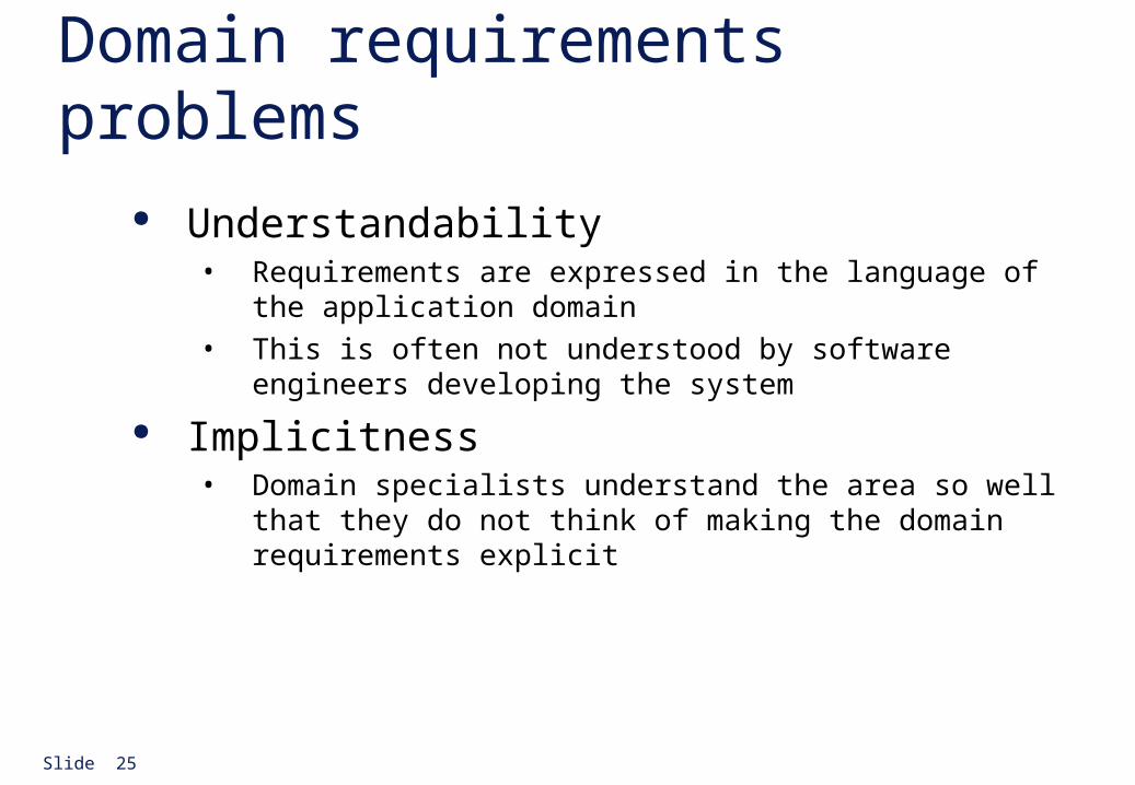
Domain requirements problems Understandability
• Requirements are expressed in the language of the application domain
• This is often not understood by software engineers developing the system
Implicitness• Domain specialists understand the area so well that they do not think
of making the domain requirements explicit
Slide 26
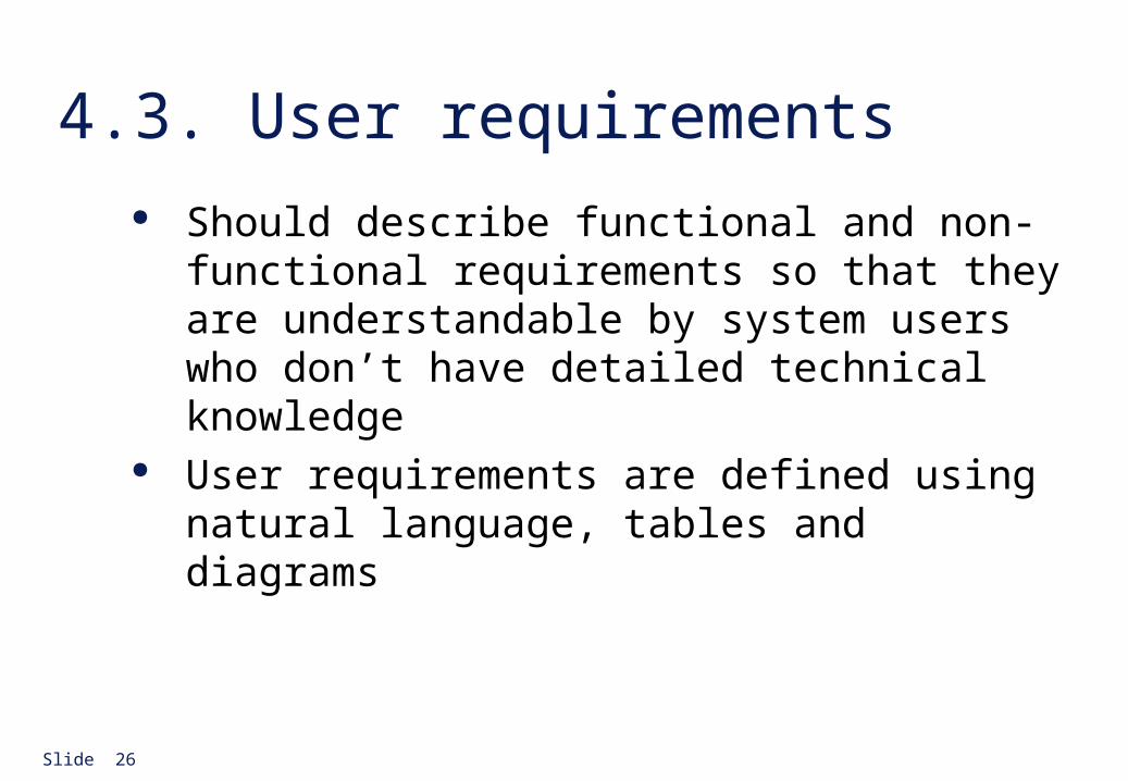
4.3. User requirements Should describe functional and non-functional
requirements so that they are understandable by system users who don’t have detailed technical knowledge
User requirements are defined using natural language, tables and diagrams
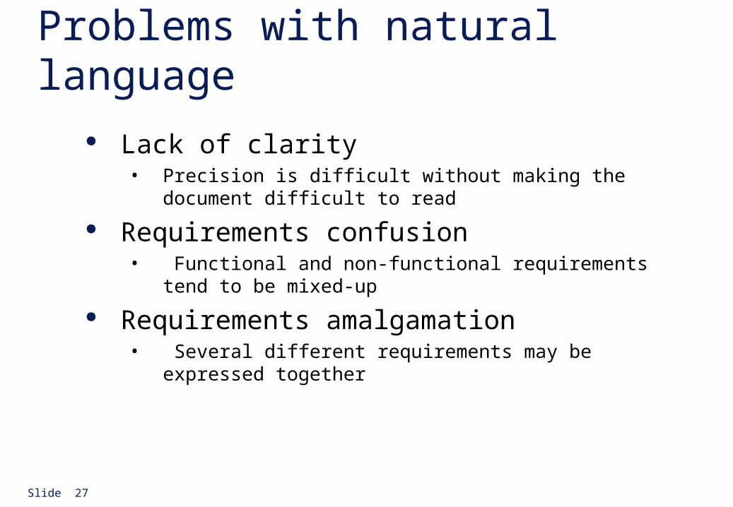
Slide 27
Problems with natural language Lack of clarity
• Precision is difficult without making the document difficult to read
Requirements confusion• Functional and non-functional requirements tend to be mixed-up
Requirements amalgamation• Several different requirements may be expressed together
Slide 28
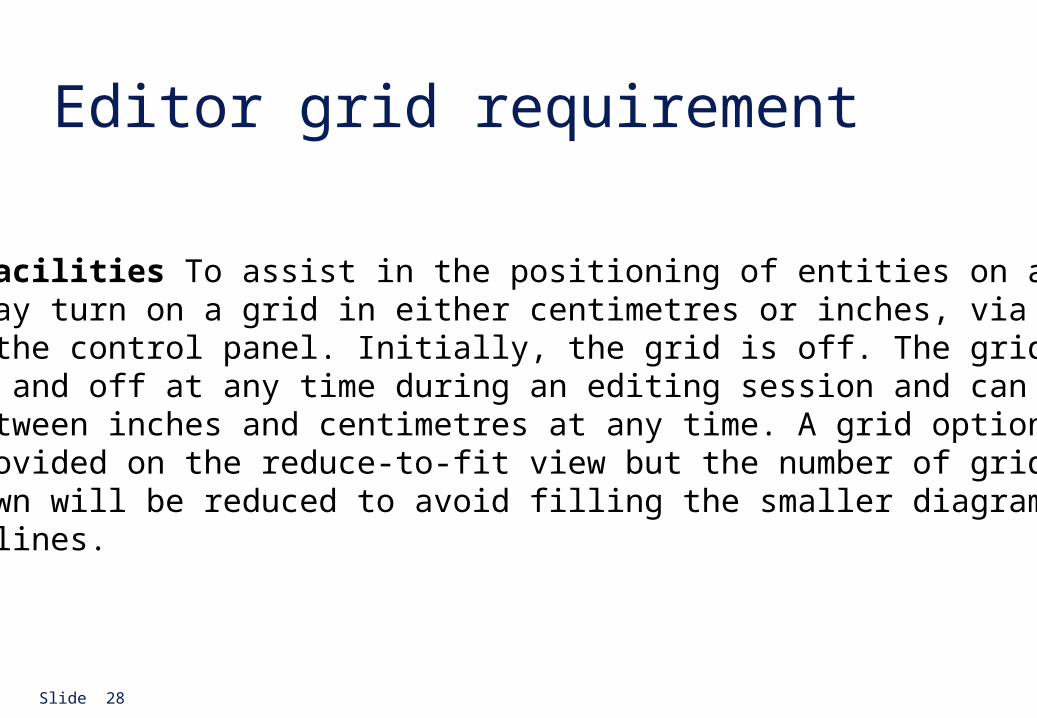
Editor grid requirement
2.6 Grid facilities To assist in the positioning of entities on a diagram, the user may turn on a grid in either centimetres or inches, via an option on the control panel. Initially, the grid is off. The grid may be turned on and off at any time during an editing session and can be toggled between inches and centimetres at any time. A grid option will be provided on the reduce-to-fit view but the number of grid lines shown will be reduced to avoid filling the smaller diagram with grid lines.
Slide 29
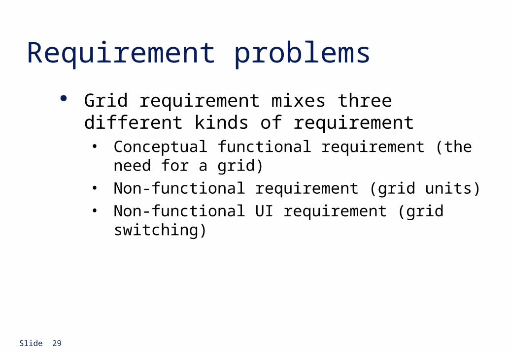
Requirement problems Grid requirement mixes three different kinds of
requirement• Conceptual functional requirement (the need for a grid)
• Non-functional requirement (grid units)
• Non-functional UI requirement (grid switching)
Slide 30
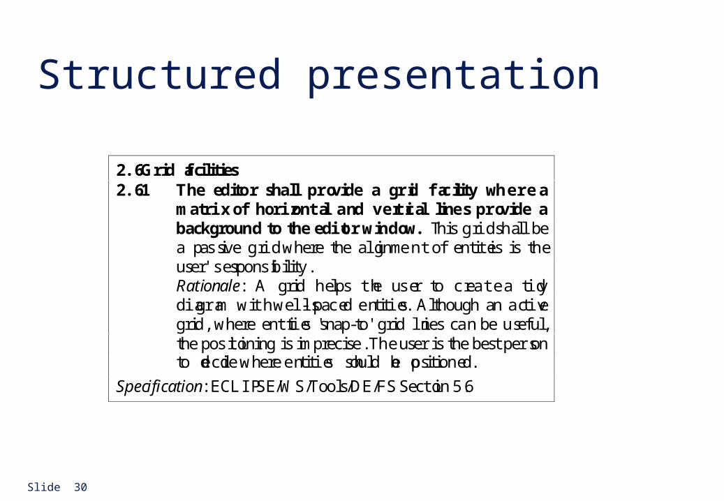
Structured presentation
2.6 Grid facilities2.6.1 The editor shall provide a grid facility where a
matrix of horizontal and vertical lines provide abackground to the editor window. T his grid shall bea p assive grid where the alignment of entities is theuser's responsibility.Rationale: A grid helps the user to create a tidydiagram with well-spaced entities. Although an activegrid, where entities 'snap-to' grid lines can be useful,the positioning is imprecise. The user is the best personto decide where entities should be positioned.
Specification: ECLIPSE/WS/Tools/DE/FS Section 5.6

Slide 31
Detailed user requirement
3.5.1 Adding nodes to a design3.5.1.1 The editor shall provide a f acility for users to add nodes of a specified type to their
design.
3.5.1.2 The sequence of actions to add a node should be as follows:
1. The user should select the type of node to be added.
2. The user should move the cursor to the approximate node position in the diagram andindicate that the node symbol should be added at that point.
3. The user should then drag the node symbol to its final position.
Rationale: The user is the best person to decide where to position a node on the diagram.This approach gives the user direct control over node type selection and positioning.
Specification: ECLIPSE/WS/Tools/DE/FS. Section 3.5.1
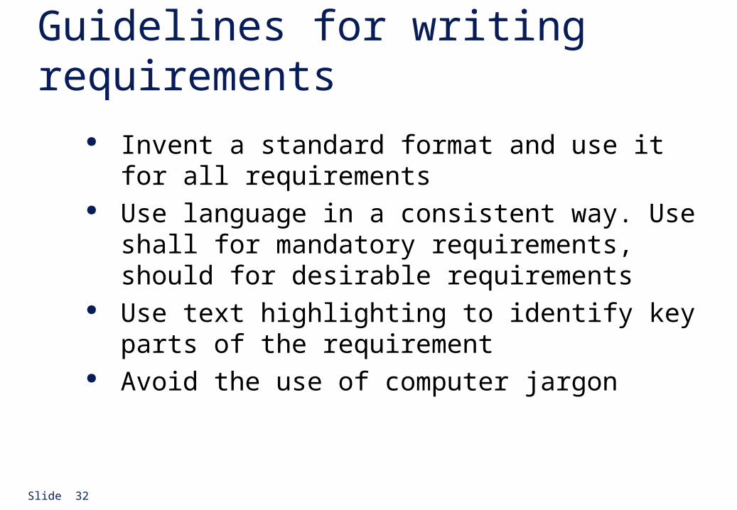
Slide 32
Guidelines for writing requirements Invent a standard format and use it for all
requirements Use language in a consistent way. Use shall for
mandatory requirements, should for desirable requirements
Use text highlighting to identify key parts of the requirement
Avoid the use of computer jargon
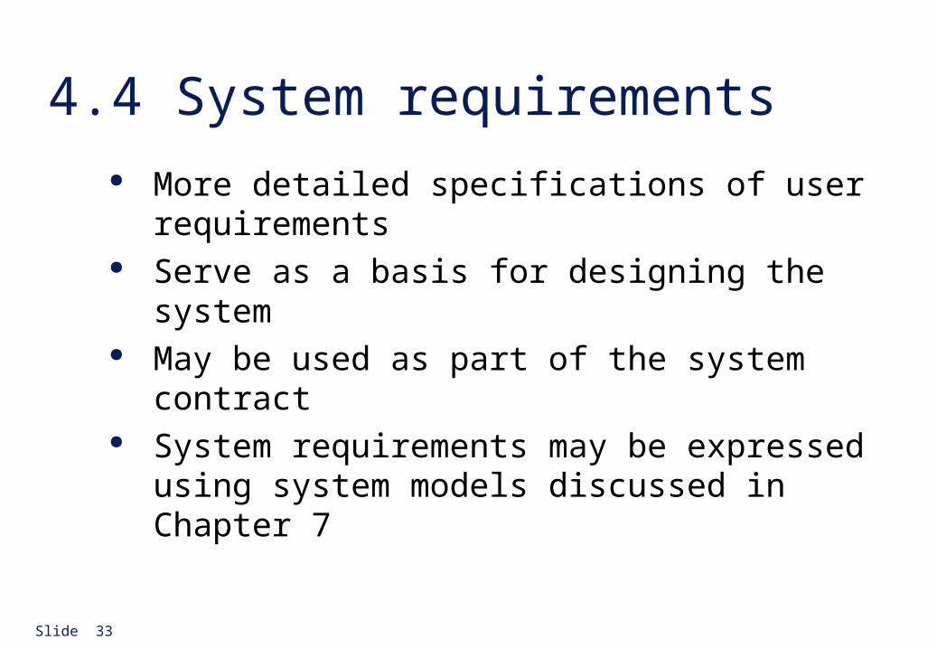
Slide 33
4.4 System requirements More detailed specifications of user requirements Serve as a basis for designing the system May be used as part of the system contract System requirements may be expressed using system
models discussed in Chapter 7
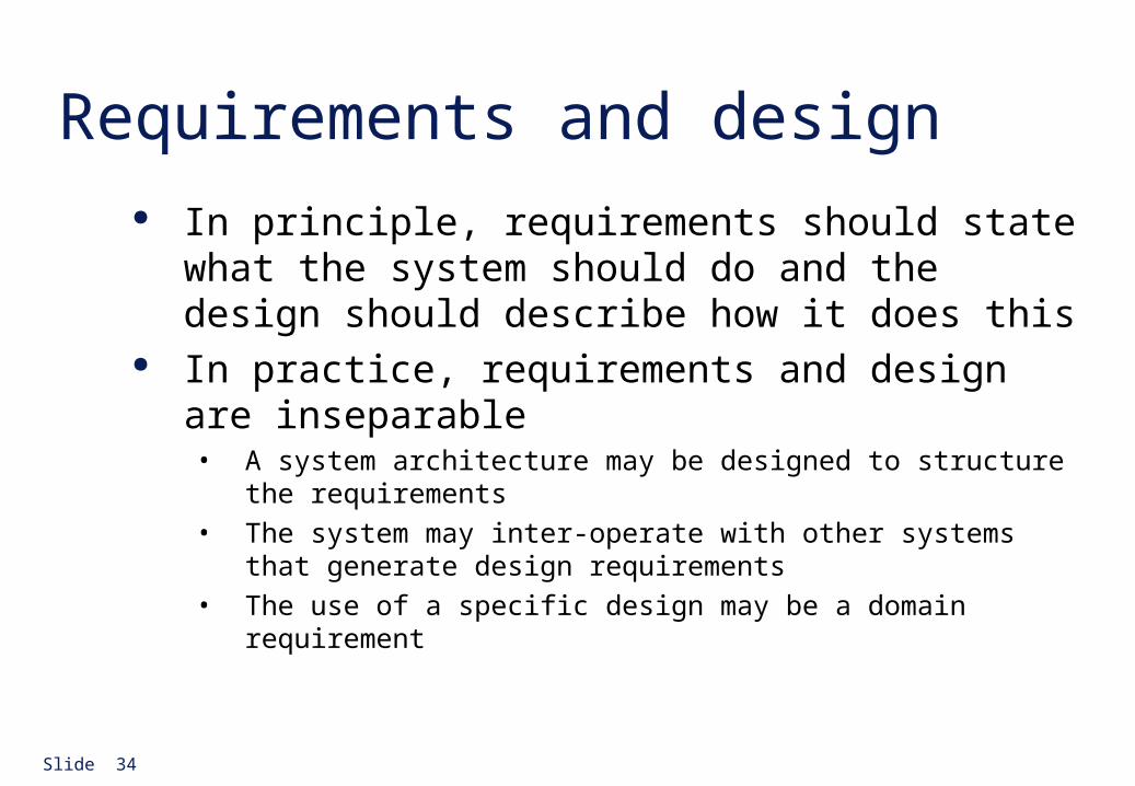
Slide 34
Requirements and design In principle, requirements should state what the
system should do and the design should describe how it does this
In practice, requirements and design are inseparable• A system architecture may be designed to structure the requirements
• The system may inter-operate with other systems that generate design requirements
• The use of a specific design may be a domain requirement
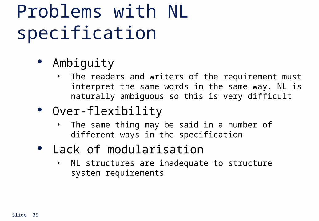
Slide 35
Problems with NL specification Ambiguity
• The readers and writers of the requirement must interpret the same words in the same way. NL is naturally ambiguous so this is very difficult
Over-flexibility• The same thing may be said in a number of different ways in the
specification
Lack of modularisation• NL structures are inadequate to structure system requirements
Slide 36
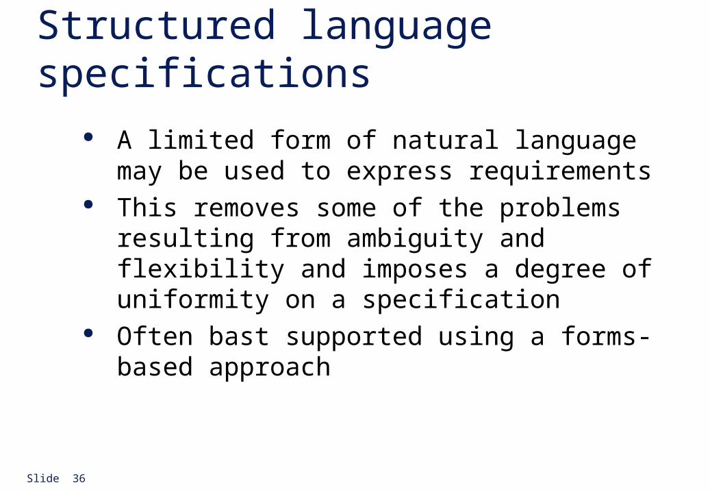
Structured language specifications A limited form of natural language may be used to
express requirements This removes some of the problems resulting from
ambiguity and flexibility and imposes a degree of uniformity on a specification
Often bast supported using a forms-based approach
Slide 37
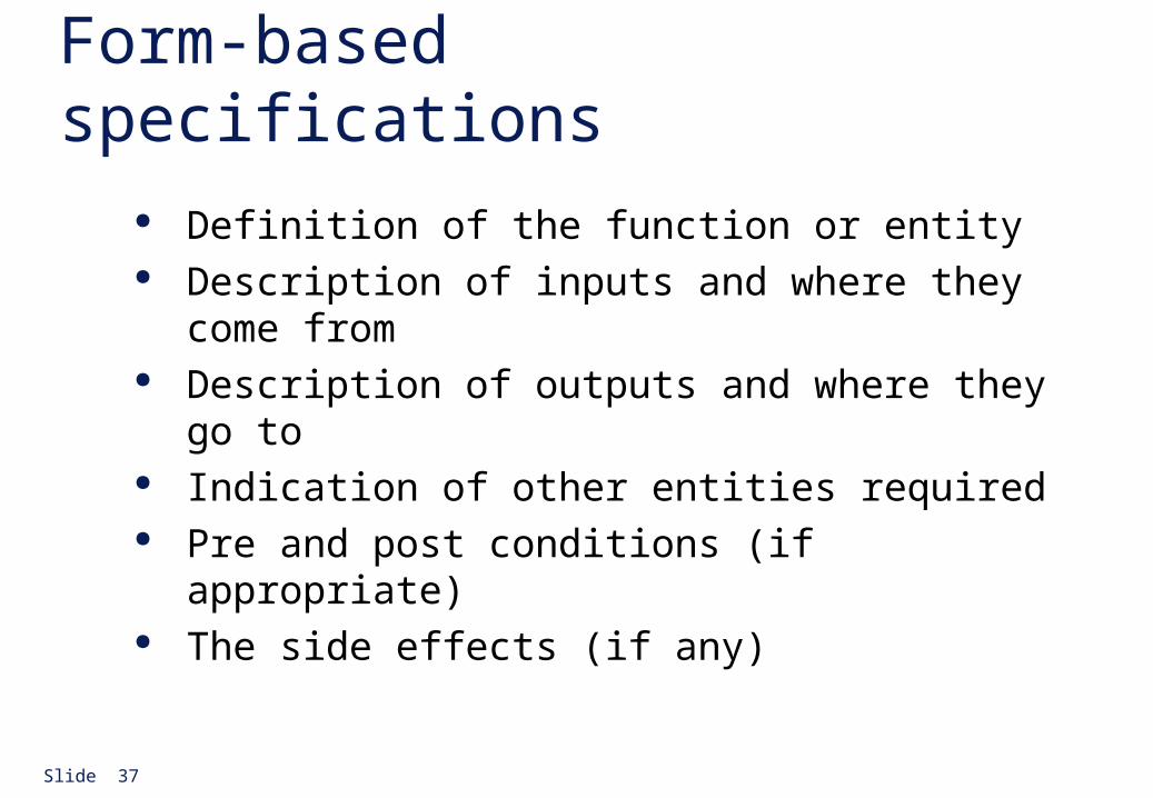
Form-based specifications Definition of the function or entity Description of inputs and where they come from Description of outputs and where they go to Indication of other entities required Pre and post conditions (if appropriate) The side effects (if any)
Slide 38
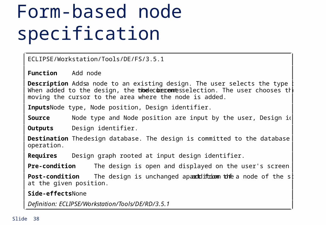
Form-based node specificationECLIPSE/Workstation/Tools/DE/FS/3.5.1
Function Add node
Description Adds a node to an existing design. The user selects the type of node, and its position.When added to the design, the node becomes the current selection. The user chooses the node position bymoving the cursor to the area where the node is added.
Inputs Node type, Node position, Design identifier.
Source Node type and Node position are input by the user, Design identifier from the database.
Outputs Design identifier.
Destination The design database. The design is committed to the database on completion of theoperation.
Requires Design graph rooted at input design identifier.
Pre-condition The design is open and displayed on the user's screen.
Post-condition The design is unchanged apart from the addition of a node of the specified typeat the given position.
Side-effects None
Definition: ECLIPSE/Workstation/Tools/DE/RD/3.5.1
Slide 39
PDL-based requirements definition Requirements may be defined operationally using a
language like a programming language but with more flexibility of expression
Most appropriate in two situations• Where an operation is specified as a sequence of actions
and the order is important
• When hardware and software interfaces have to be specified
Slide 40
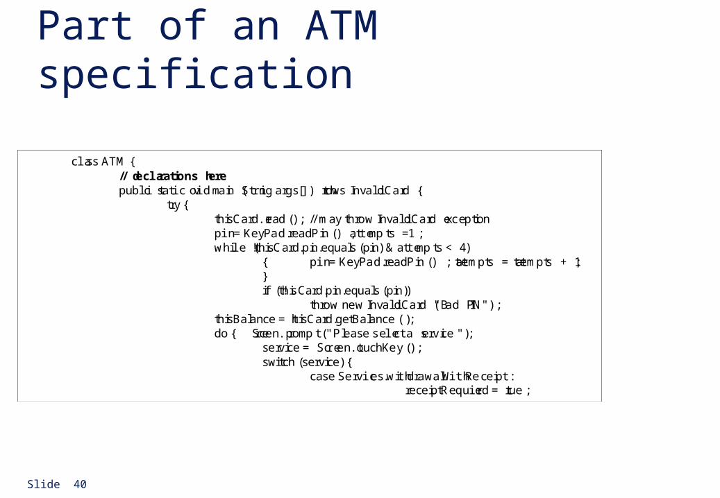
Part of an ATM specification
class ATM {// declarations herepublic static void main (String args[]) throws InvalidCard {
try {thisCard.read () ; // may throw InvalidCard exceptionpin = KeyPad.readPin () ; attempts = 1 ;while ( !thisCard.pin.equals (pin) & attempts < 4 )
{ pin = KeyPad.readPin () ; attempts = attempts + 1 ;}if (!thisCard.pin.equals (pin))
throw new InvalidCard ("Bad PIN");thisBalance = thisCard.getBalance () ;do { Screen.prompt (" Please select a service ") ;
service = Screen.touchKey () ;switch (service) {
case Services.withdrawalWithReceipt:receiptRequired = true ;
Slide 41
PDL disadvantages PDL may not be sufficiently expressive to express the
system functionality in an understandable way Notation is only understandable to people with
programming language knowledge The requirement may be taken as a design
specification rather than a model to help understand the system
Slide 42
Interface specification Most systems must operate with other systems and the
operating interfaces must be specified as part of the requirements
Three types of interface may have to be defined• Procedural interfaces
• Data structures that are exchanged
• Data representations
Formal notations are an effective technique for interface specification
Slide 43
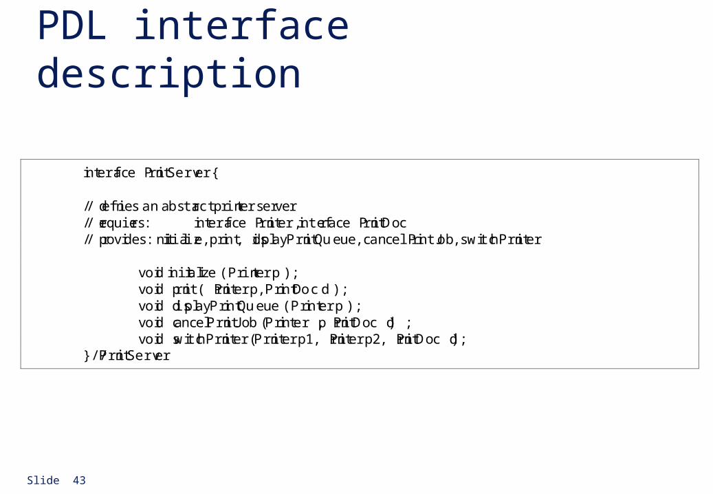
PDL interface description
interface PrintServer {
// defines an abstract printer server// requires: interface Printer, interface PrintDoc// provides: initialize, print, displayPrintQueue, cancelPrintJob, switchPrinter
void initialize ( Printer p ) ;void print ( Printer p, PrintDoc d ) ;void displayPrintQueue ( Printer p ) ;void cancelPrintJob (Printer p, PrintDoc d) ;void switchPrinter (Printer p1, Printer p2, PrintDoc d) ;
} //PrintServer
Slide 44
4.5 The requirements document The requirements document is the official statement
of what is required of the system developers Should include both a definition and a specification of
requirements It is NOT a design document. As far as possible, it
should set of WHAT the system should do rather than HOW it should do it
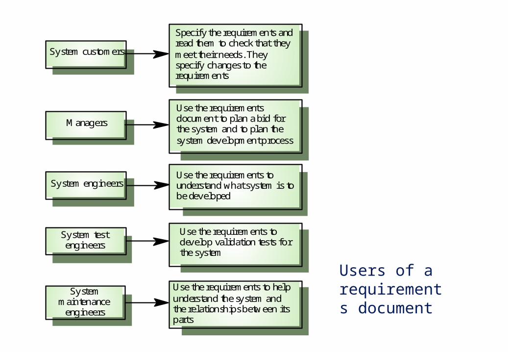
Users of a requirements document
Use the requirements todevelop validation tests forthe system
Use the requirementsdocument to plan a bid forthe system and to plan thesystem development process
Use the requirements tounderstand what system is tobe developed
System testengineers
Managers
System engineers
Specify the requirements andread them to check that theymeet their needs. Theyspecify changes to therequirements
System customers
Use the requirements to helpunderstand the system andthe relationships between itsparts
Systemmaintenance
engineers
Slide 46
Requirements document requirements Specify external system behaviour Specify implementation constraints Easy to change Serve as reference tool for maintenance Record forethought about the life cycle of the system
i.e. predict changes Characterise responses to unexpected events
Slide 47
IEEE requirements standard Introduction General description Specific requirements Appendices Index
This is a generic structure that must be instantiated for specific systems
Slide 48
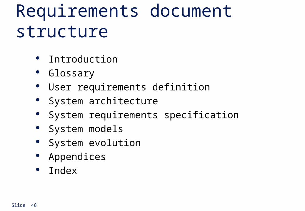
Requirements document structure Introduction Glossary User requirements definition System architecture System requirements specification System models System evolution Appendices Index


![Slide 1 [S2001, Cap. 5] [AC96, Cap. 1] u Functional, non-functional, domain requirements u User requirements u System and software requirements u Requirements](https://img.dokumen.tips/doc/110x75/5542eb4f497959361e8be739/slide-1-s2001-cap-5-ac96-cap-1-u-functional-non-functional-domain-requirements-u-user-requirements-u-system-and-software-requirements-u-requirements.jpg)