Embed Size (px)
Citation preview
CORONAS // SERIE LIGERA // ARO MACIZO DENTADO EXTERIOR
SLEWING BEARINGS,SLEW WORM GEAR AND LINEAR ACTUATOR TECHNOLOGY
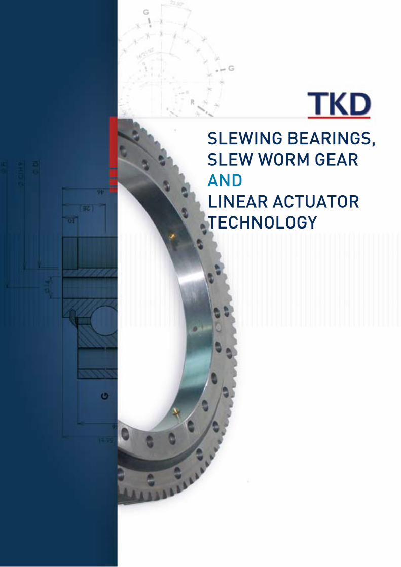
Application: AXIS OF ROTATION:
HORIZONTAL VERTICAL MUTUAL
BEARING UNDER:
COMPRESSION TENSION* BOLTS UNDER TENSION BY AXIAL LOADS
GEAR:
EXTERNAL INTERNAL WITHOUT
MOVEMENT
POSITIONING ONLY INTERMITTENT ROTATION CONTINOUS ROTATION
NO. OF REVOLUTIONS (rpm):
NORMAL:MAXIMUM:
MAGNITUDE AND DIRECTION OF LOADS AND
THEIR DISTANCE (RELATED TO AXIS OF ROTATION)
MAX. WORKING LOAD MAX. TEST LOAD E:G: 25% OVERLOAD CONDITIONS
EXTREME LOAD E.G. SHOCKS OR OUT OF
OPERATION
AXIAL LOADS (KN)
RADIAL LOADS(KN)
TILTING MOMENT(KNm)
DRIVEN TORQUE(KNm): normal ______ max ______ number of Pinion: _______
REMARKS: (E.G. SPECIAL WORKING CONDITIONS/TEMPERATURES, REQUIERED ACCURANCIES, BEARING DIMENSIONS, INSPECTION-OR CERTIFICATION REQUIREMENTS, MATERIAL TESTS, ETC.)
SPECIFIED LOAD CONDITIONS
AXIAL LOAD (KN) RADIAL LOAD(KN)
TILTING MOMENT(KNm)
SPEED (rpm) WORKING TIME (%)
1)
2)
3)
4)
5)
...
CONTINOUS ROTATIONLIFE CYCLE: NORMAL RATATION SPEED AT _________ rpm, THE REQUIRED ROTATION HOURS SHOULD BE ____
INTERMITTENT ROTATIONREQUIERED LIFE CYCLE: THE ANGLE IS AT +/- _______ DEGREE, THE CYCLES SHOULD BE AT LEAST _________
// BEARINGS LOAD
// DATA SHEET FOR BEARING SELECTION
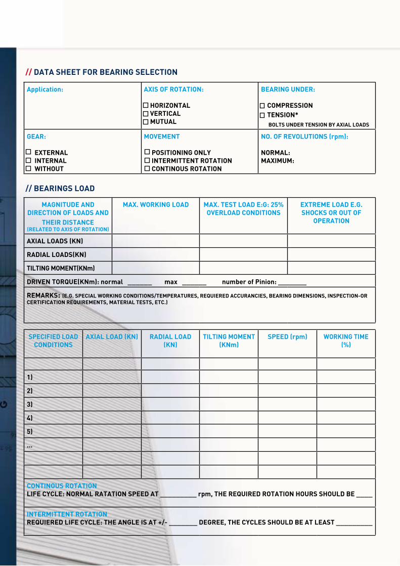
TECNOMECA-KIDELAN, located in the Basque country of Spain, is a leading company in the field of international distribution of industrial sophisticated products. The company was founded in 2006 and is the result of a strategically merger of two companies, who decided to combine their strenghts:
Tecnomeca S.A.: For more than 30 years Tecnomeca SA with its experience and competence has been one of worlwide´s leading suppliers of linear technology, precision bearings, machine tools components, slewing bearings, aluminium profiles/systems, precision balls and components for various industrial applications.
Kidelan S.L. Kidelan, S.L. was founded in 1996 and is a specialist in the field of mechanical transmission and compo-nents. All items can be offered as standard or after customers drawing and specifications.
The comprehensive product range, the individual service and the consistent quality of our products are the basis for a long-term and trusted relationship between our customers, employees and suppliers.
TECNOMECA-KIDELAN is primarily concerned with achieving the requirements and expectations of its customers. Our corporate goal is to provide our worldwide customers products and services of the highest quality and competi-tive market conditions.
Customer orientation, individual consultation and common conception are the basis for a successful implementation of our customers’ wishes.
In the area of slew rings TECNOMECA-KIDELAN is specialized in bearings until 4.500 mm outer diameter. All our bearings can be supplied as follows:
- with external, internal or without gear- single or double row of balls/rollers- standard or customer drawing requirement
All service and areas of design and manufacturing are based on the international DIN EN ISO 9001:2000. The effi-ciency of our quality assurance is proven by stipulated periodical internal audits.
// COMPANY PROFILE

// SLEWING BEARINGS CODE
161 20 0505 3000
161 1 single row
2 double row
3 triple row
1 four point contact bearings
8 rollers
6 light Serie
7 solid light serie
2 angular contact double row
4 ball-roller combination
1 external gear
2 internal gear
3 without gear
4 external helical
5 external worm gear
6 special
diameter ball/roller
1 material C45k
2 material 42Cr Mo Q+T
3 material 50 Mn
0 unhardened teeth
1 hardened teeth by induction
0 standard clearance
1 preload
2 superprecision
0 standard
1 corrected gear
2 not cataloged modul
3 others (specify)
diameter external slew ring 3000
In order to understand our references, please pay attention to the following description.
4
161 external gear 162 internal gear 163 without gear
171 external gear 172 internal gear 173 without gear
// LIGHT SERIES WITH SOLID RINGS
// LIGHT SERIE

111
181
211
221
241
112
182
212
281
381
113
183
213
282
383
5
Our large product range of slewing bearings can be equipped with balls or/and rollers.Below you will find an overview concerning the most suitable slewing bearings.
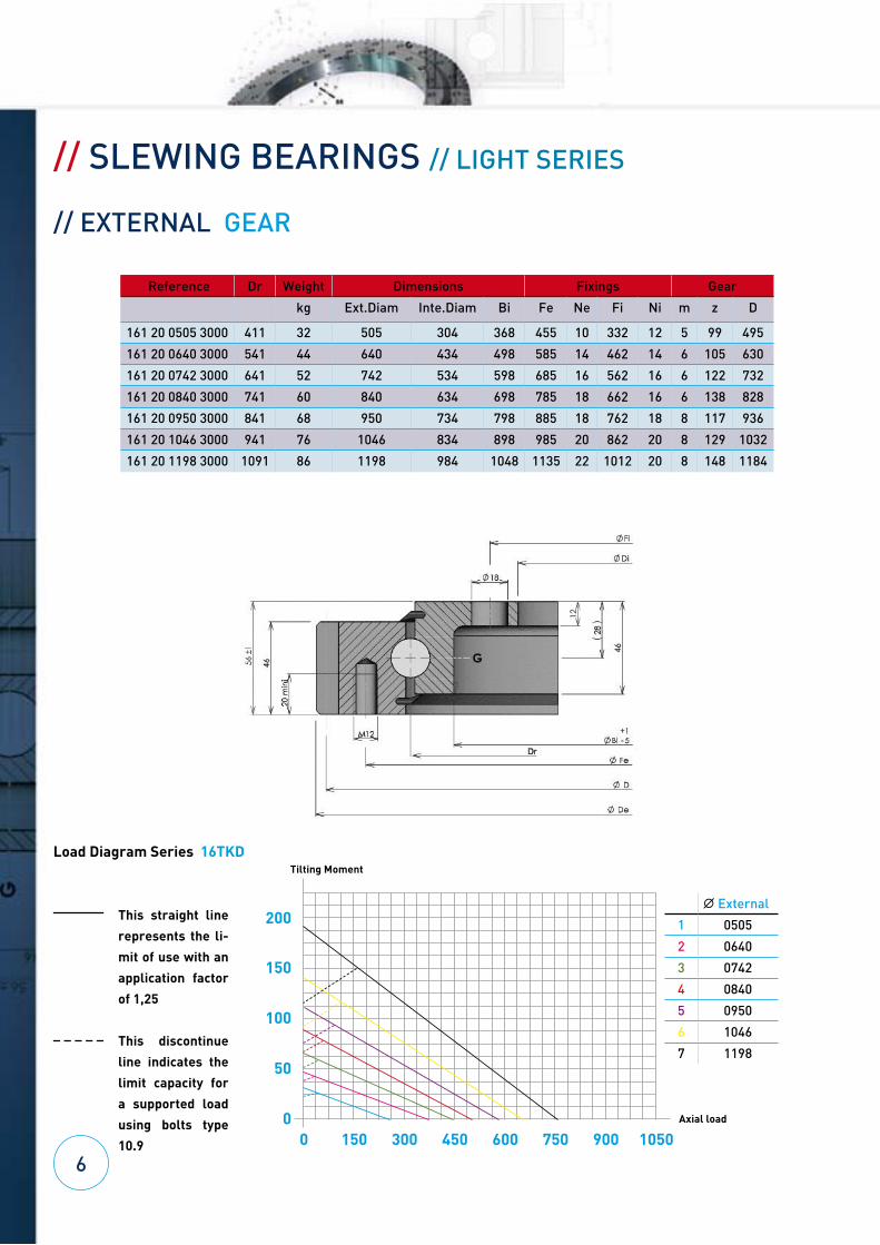
// SLEWING BEARINGS // LIGHT SERIES
// EXTERNAL GEAR
Reference Dr Weight Dimensions Fixings Gear
kg Ext.Diam Inte.Diam Bi Fe Ne Fi Ni m z D
161 20 0505 3000 411 32 505 304 368 455 10 332 12 5 99 495
161 20 0640 3000 541 44 640 434 498 585 14 462 14 6 105 630
161 20 0742 3000 641 52 742 534 598 685 16 562 16 6 122 732
161 20 0840 3000 741 60 840 634 698 785 18 662 16 6 138 828
161 20 0950 3000 841 68 950 734 798 885 18 762 18 8 117 936
161 20 1046 3000 941 76 1046 834 898 985 20 862 20 8 129 1032
161 20 1198 3000 1091 86 1198 984 1048 1135 22 1012 20 8 148 1184
Load Diagram Series 16TKD
61050
200
150
100
50
90075060045030015000 Axial load
Tilting Moment
This straight line
represents the li-
mit of use with an
application factor
of 1,25
This discontinue
line indicates the
limit capacity for
a supported load
using bolts type
10.9
B External
1 0505
2 0640
3 0742
4 0840
5 0950
6 1046
7 1198
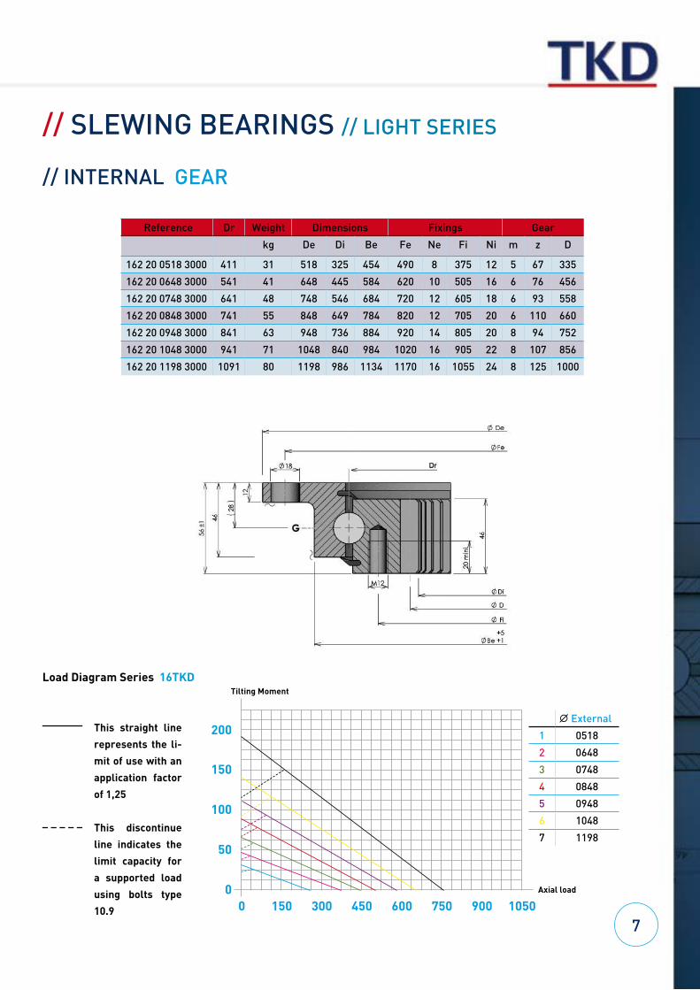
// SLEWING BEARINGS // LIGHT SERIES
// INTERNAL GEAR
Reference Dr Weight Dimensions Fixings Gear
kg De Di Be Fe Ne Fi Ni m z D
162 20 0518 3000 411 31 518 325 454 490 8 375 12 5 67 335
162 20 0648 3000 541 41 648 445 584 620 10 505 16 6 76 456
162 20 0748 3000 641 48 748 546 684 720 12 605 18 6 93 558
162 20 0848 3000 741 55 848 649 784 820 12 705 20 6 110 660
162 20 0948 3000 841 63 948 736 884 920 14 805 20 8 94 752
162 20 1048 3000 941 71 1048 840 984 1020 16 905 22 8 107 856
162 20 1198 3000 1091 80 1198 986 1134 1170 16 1055 24 8 125 1000
7
Load Diagram Series 16TKD
1050
200
150
100
50
90075060045030015000 Axial load
Tilting Moment
This straight line
represents the li-
mit of use with an
application factor
of 1,25
This discontinue
line indicates the
limit capacity for
a supported load
using bolts type
10.9
B External
1 0518
2 0648
3 0748
4 0848
5 0948
6 1048
7 1198
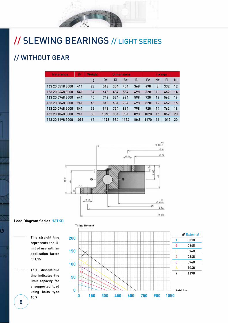
// SLEWING BEARINGS // LIGHT SERIES
// WITHOUT GEAR
Reference Dr Weight Dimensions Fixings
kg De Di Be BI Fe Ne Fi Ni
163 20 0518 3000 411 23 518 304 454 368 490 8 332 12
163 20 0648 3000 541 34 648 434 584 498 620 10 462 14
163 20 0748 3000 641 40 748 534 684 598 720 12 562 16
163 20 0848 3000 741 46 848 634 784 698 820 12 662 16
163 20 0948 3000 841 52 948 734 884 798 920 14 762 18
163 20 1048 3000 941 58 1048 834 984 898 1020 16 862 20
163 20 1198 3000 1091 67 1198 984 1134 1048 1170 16 1012 20
8
200
150
100
50
0
Tilting Moment
Load Diagram Series 16TKD
This straight line
represents the li-
mit of use with an
application factor
of 1,25
This discontinue
line indicates the
limit capacity for
a supported load
using bolts type
10.9
B External
1 0518
2 0648
3 0748
4 0848
5 0948
6 1048
7 1198
10509007506004503001500 Axial load
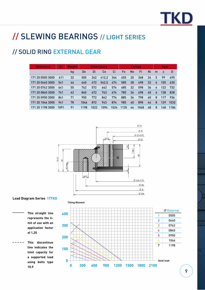
// SLEWING BEARINGS // LIGHT SERIES
// SOLID RING EXTERNAL GEAR
Reference Dr Weight Dimensions Fixings Gear
kg De Di Ce Ci Fe Ne Fi Ni m z D
171 20 0505 3000 411 32 505 342 412,2 344 455 20 368 24 5 99 495
171 20 0640 3000 541 46 640 472 542,5 474 585 28 498 32 6 105 630
171 20 0742 3000 641 55 742 572 642 574 685 32 598 36 6 122 732
171 20 0840 3000 741 62 840 672 743 674 785 36 698 40 6 138 828
171 20 0950 3000 841 71 950 772 842 774 885 36 798 40 8 117 936
171 20 1046 3000 941 78 1046 872 943 874 985 40 898 44 8 129 1032
171 20 1198 3000 1091 91 1198 1022 1094 1024 1135 44 1048 48 8 148 1184
2100
400
300
200
100
18001500120090060030000 Axial load
Tilting Moment
Load Diagram Series 17TKD
This straight line
represents the li-
mit of use with an
application factor
of 1,25
This discontinue
line indicates the
limit capacity for
a supported load
using bolts type
10.9
9
B External
1 0505
2 0640
3 0742
4 0840
5 0950
6 1046
7 1198
// SLEWING BEARINGS // LIGHT SERIES
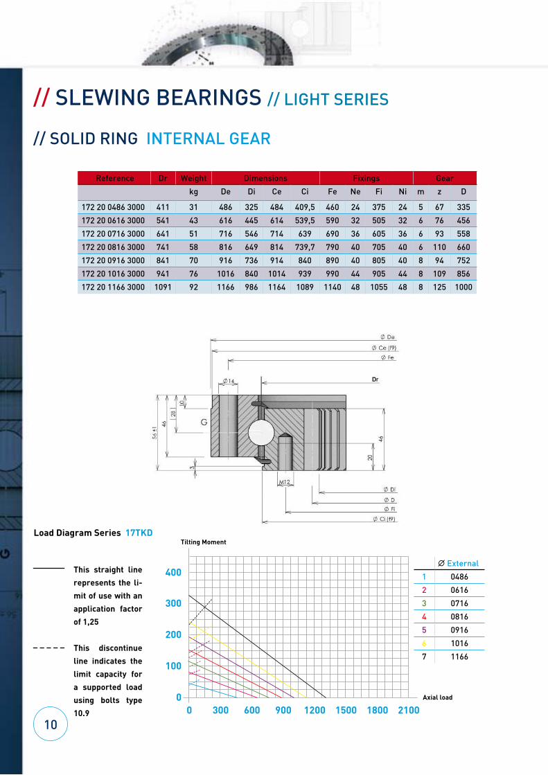
// SOLID RING INTERNAL GEAR
Reference Dr Weight Dimensions Fixings Gear
kg De Di Ce Ci Fe Ne Fi Ni m z D
172 20 0486 3000 411 31 486 325 484 409,5 460 24 375 24 5 67 335
172 20 0616 3000 541 43 616 445 614 539,5 590 32 505 32 6 76 456
172 20 0716 3000 641 51 716 546 714 639 690 36 605 36 6 93 558
172 20 0816 3000 741 58 816 649 814 739,7 790 40 705 40 6 110 660
172 20 0916 3000 841 70 916 736 914 840 890 40 805 40 8 94 752
172 20 1016 3000 941 76 1016 840 1014 939 990 44 905 44 8 109 856
172 20 1166 3000 1091 92 1166 986 1164 1089 1140 48 1055 48 8 125 1000
102100
400
300
200
100
18001500120090060030000 Axial load
Tilting MomentLoad Diagram Series 17TKD
This straight line
represents the li-
mit of use with an
application factor
of 1,25
This discontinue
line indicates the
limit capacity for
a supported load
using bolts type
10.9
B External
1 0486
2 0616
3 0716
4 0816
5 0916
6 1016
7 1166
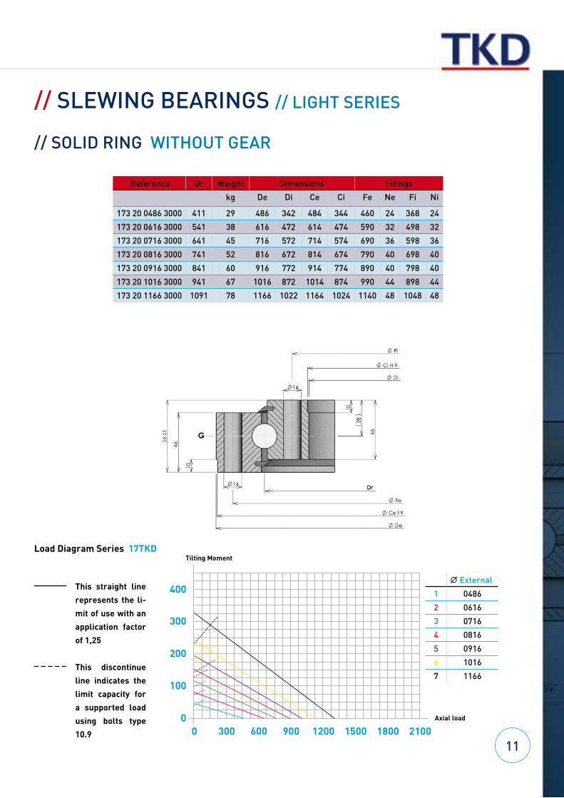
// SLEWING BEARINGS // LIGHT SERIES
// SOLID RING WITHOUT GEAR
Reference Dr Weight Dimensions Fixings
kg De Di Ce Ci Fe Ne Fi Ni
173 20 0486 3000 411 29 486 342 484 344 460 24 368 24
173 20 0616 3000 541 38 616 472 614 474 590 32 498 32
173 20 0716 3000 641 45 716 572 714 574 690 36 598 36
173 20 0816 3000 741 52 816 672 814 674 790 40 698 40
173 20 0916 3000 841 60 916 772 914 774 890 40 798 40
173 20 1016 3000 941 67 1016 872 1014 874 990 44 898 44
173 20 1166 3000 1091 78 1166 1022 1164 1024 1140 48 1048 48
112100
400
300
200
100
18001500120090060030000 Axial load
Tilting MomentLoad Diagram Series 17TKD
This straight line
represents the li-
mit of use with an
application factor
of 1,25
This discontinue
line indicates the
limit capacity for
a supported load
using bolts type
10.9
B External
1 0486
2 0616
3 0716
4 0816
5 0916
6 1016
7 1166

// SLEW DRIVES // WORM GEAR SHAFT
- Compact and sealed units- Maximum load capacity and compact design- Single or double row of balls- Hardened and grounded worm gear- High torque and elevated ratio- Extended life/reduced maintenance cost- Economical solution and easy assembling
Tecnomeca-Kidelan supplies as an option the electronic components of the slew drive.
12

// SLEW DRIVES // WORM GEAR SHAFTS // TKGI 223-1
13
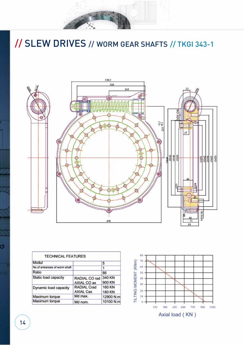
// SLEW DRIVES // WORM GEAR SHAFTS // TKGI 343-1
14
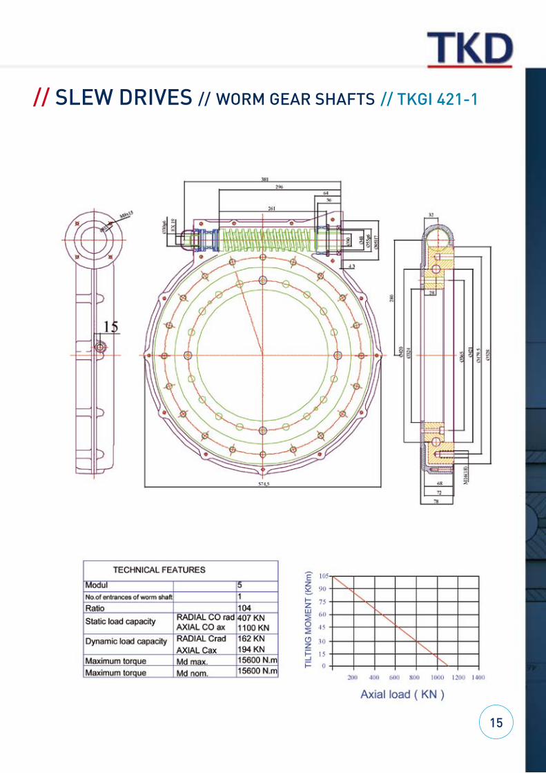
// SLEW DRIVES // WORM GEAR SHAFTS // TKGI 421-1
15
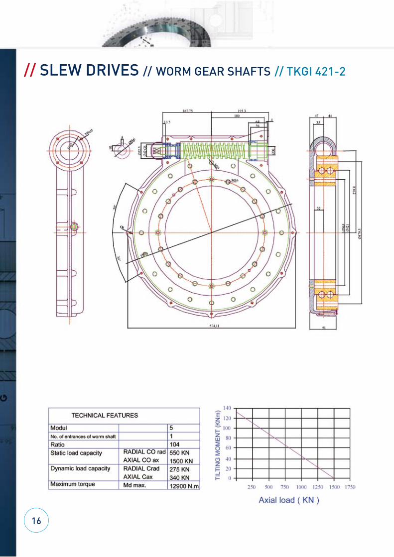
// SLEW DRIVES // WORM GEAR SHAFTS // TKGI 421-2
16
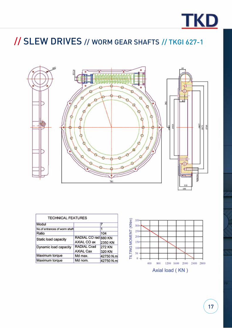
// SLEW DRIVES // WORM GEAR SHAFTS // TKGI 627-1
17
18
// MECHANICAL LINEAR ACTUATOR TECHNOLOGY
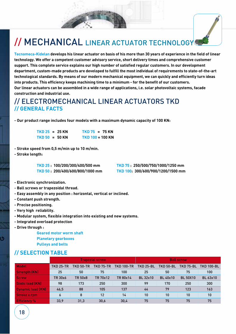
Trapezial screw Ball screw
Model TKD 25-TR TKD 50-TR TKD 75-TR TKD 100-TR TKD 25-BL TKD 50-BL TKD 75-BL TKD 100-BL
Strength (KN) 25 50 75 100 25 50 75 100
Screw TR 30x6 TR 50x8 TR 70x12 TR 80x14 BL 32x10 BL 40x10 BL 50X10 BL 63x10
Static load (KN) 98 173 250 300 99 170 250 300
Dynamic load (KN) 46,5 88 105 137 44 79 123 163
Stroke x rpm 6 8 12 14 10 10 10 10
Efficiency % 33,9 31,3 30,6 30,4 75 75 75 75
TKD 75 = 75 KNTKD 100 = 100 KN
TKD 75 : 250/500/750/1000/1250 mmTKD 100: 300/600/900/1200/1500 mm
Tecnomeca-Kidelan develops his linear actuator on basis of his more than 30 years of experience in the field of linear technology. We offer a competent customer advisory service, short delivery times and comprehensive customer support. This complete service explains our high number of satisfied regular customers. In our development department, custom-made products are developed to fulfill the most individual of requirements to state-of-the-art technological standards. By means of our modern mechanical equipment, we can quickly and efficiently turn ideas into products. This efficiency keeps machining time to a minimum - for the benefit of our customers. Our linear actuators can be assembled in a wide range of applications, i.e. solar photovoltaic systems, facade construction and industrial use.
// ELECTROMECHANICAL LINEAR ACTUATORS TKD// GENERAL FACTS
- Our product range includes four models with a maximum dynamic capacity of 100 KN:
TKD 25 = 25 KNTKD 50 = 50 KN
- Stroke speed from 0,5 m/min up to 10 m/min.- Stroke length:
TKD 25 : 100/200/300/400/500 mmTKD 50 : 200/400/600/800/1000 mm
- Electronic synchronization.- Ball screws or trapezoidal thread.- Easy assembly in any position : horizontal, vertical or inclined.- Constant push strength.- Precise positioning.- Very high reliability.- Modular system, flexible integration into existing and new systems.- Integrated overload protection- Drive through :
Geared motor worm shaftPlanetary gearboxesPulleys and belts
// SELECTION TABLE

19
// OPERATION DATA SHEAT
Our data sheet are based on dynamic load capacities and with a factor of 20% of cycles/hour.It is not recommended to apply the linear actuators which are in the shady boxes of the table because in this case they would reduce considerably the life cycle of the linear actuator.
Requirements for TKD 25-BL : Ball srew 32 pitch 10
Requirements for TKD 50-BL : Ball screw 40 pitch 10
Requirements for TKD 75-BL : Ball screw 50 pitch 10
Requirements for TKD 100-BL : Ball screw 63 pitch 10
Speed Stroke length 25 KN 20 KN 15 KN 10 KN 5 KN
(rpm) (m/min) Nm KW Nm KW Nm KW Nm KW Nm KW
700 7 53 3,9 42 3,1 32 2,3 21 1,6 11 0,8
500 5 53 2,8 42 2,2 32 1,7 21 1,1 11 0,6
300 3 53 1,7 42 1,3 32 1,0 21 0,7 11 0,3
100 1 53 0,6 42 0,4 32 0,3 21 0,2 11 0,1
50 0,5 53 0,3 42 0,2 32 0,2 21 0,1 19 0,1
Speed Stroke length 50 KN 40 KN 30KN 25 KN 20 KN 10 KN
(rpm) (m/min) Nm KW Nm KW Nm KW Nm KW Nm KW Nm KW
450 4,5 106 5,0 85 4,0 64 3,0 53 2,5 42 2,0 21 1,0
350 3,5 106 3,9 85 3,1 64 2,3 53 1,9 42 1,6 21 0,8
200 2 106 2,2 85 1,8 64 1,3 53 1,1 42 0,9 21 0,4
100 1 106 1,1 85 0,9 64 0,7 53 0,6 42 0,4 21 0,2
50 0,5 106 0,6 85 0,4 64 0,3 53 0,3 42 0,2 21 0,1
Speed Stroke length 75 KN 60 KN 45 KN 35 KN 20 KN 10 KN
(rpm) (m/min) Nm KW Nm KW Nm KW Nm KW Nm KW Nm KW
350 3,5 136 5,0 109 4,0 82 3,0 64 2,3 42 1,5 21 0,75
275 2,75 136 3,9 109 3,0 82 2,4 64 1,8 42 1,2 21 0,6
180 1,8 136 2,6 109 2,1 82 1,6 64 1,2 42 0,8 21 0,4
90 0,9 136 1,3 109 1,1 82 0,8 64 0,6 42 0,4 21 0,2
45 0,45 136 0,65 109 0,50 82 0,4 64 0,3 42 0,2 21 0,1
Speed Stroke length 100 KN 80 KN 60 KN 50 KN 40 KN 20 KN 10 KN
(rpm) (m/min) Nm KW Nm KW Nm KW Nm KW Nm KW Nm KW Nm KW
225 2,25 212 5,0 170 4,0 127 3,0 106 2,5 85 2,0 42 1,0 21 0,5
200 2 212 4,4 170 3,6 127 2,7 106 2,2 85 1,8 42 0,9 21 0,4
160 1,6 212 3,6 170 2,8 127 2,1 106 1,8 85 1,4 42 0,7 21 0,4
80 0,8 212 1,8 170 1,4 127 1,1 106 0,9 85 0,7 42 0,4 21 0,2
40 0,4 212 0,9 170 0,7 127 0,5 106 0,4 85 0,4 42 0,2 24 0,1
20
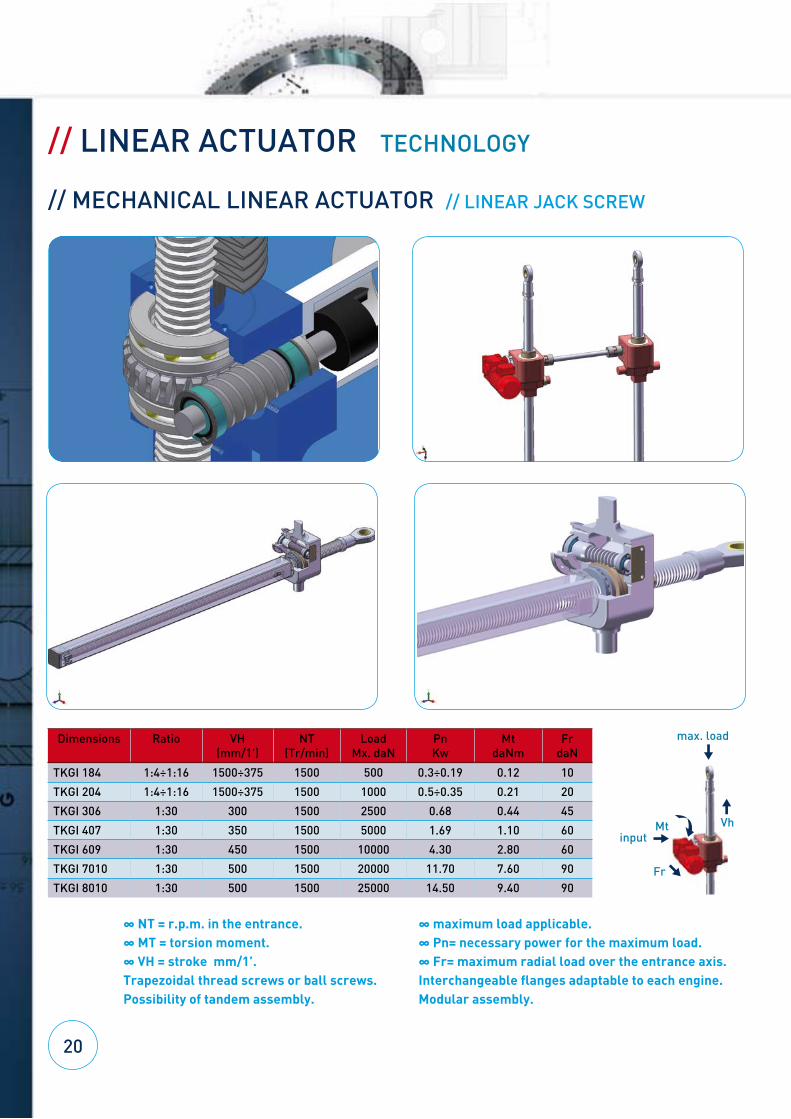
// LINEAR ACTUATOR TECHNOLOGY
// MECHANICAL LINEAR ACTUATOR // LINEAR JACK SCREW
Dimensions Ratio VH (mm/1')
NT (Tr/min)
Load Mx. daN
Pn Kw
Mt daNm
Fr daN
TKGI 184 1:4÷1:16 1500÷375 1500 500 0.3÷0.19 0.12 10
TKGI 204 1:4÷1:16 1500÷375 1500 1000 0.5÷0.35 0.21 20
TKGI 306 1:30 300 1500 2500 0.68 0.44 45
TKGI 407 1:30 350 1500 5000 1.69 1.10 60
TKGI 609 1:30 450 1500 10000 4.30 2.80 60
TKGI 7010 1:30 500 1500 20000 11.70 7.60 90
TKGI 8010 1:30 500 1500 25000 14.50 9.40 90
∞ NT = r.p.m. in the entrance. ∞ MT = torsion moment.∞ VH = stroke mm/1’. Trapezoidal thread screws or ball screws.Possibility of tandem assembly.
∞ maximum load applicable.∞ Pn= necessary power for the maximum load.∞ Fr= maximum radial load over the entrance axis.Interchangeable flanges adaptable to each engine.Modular assembly.
max. load
input
Fr
Mt Vh
Our products are used in sectors as:
- Vehicle and crane systems- Rotation of attachments such as excavators, grabs and fork lifts- Wind energy- Solar tracking systems- Water treatment- Transport systems- Light crane systems- Etc.
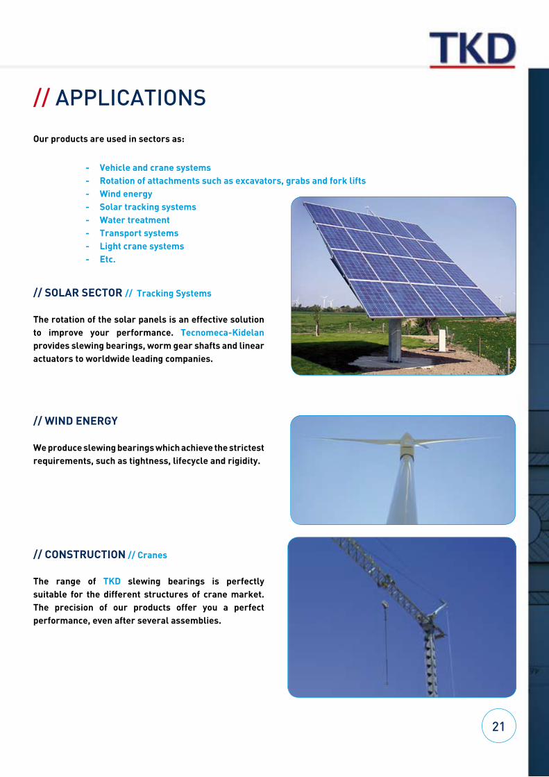
// SOLAR SECTOR // Tracking Systems
The rotation of the solar panels is an effective solution to improve your performance. Tecnomeca-Kidelan provides slewing bearings, worm gear shafts and linear actuators to worldwide leading companies.
// WIND ENERGY
We produce slewing bearings which achieve the strictest requirements, such as tightness, lifecycle and rigidity.
// CONSTRUCTION // Cranes
The range of TKD slewing bearings is perfectly suitable for the different structures of crane market. The precision of our products offer you a perfect performance, even after several assemblies.
21
// APPLICATIONS
// TOOL MACHINE AND ROBOTIC
These are the TKD slew rings precision applications. We manufacture grounded and preload slew rings suitable for the highest requirements.
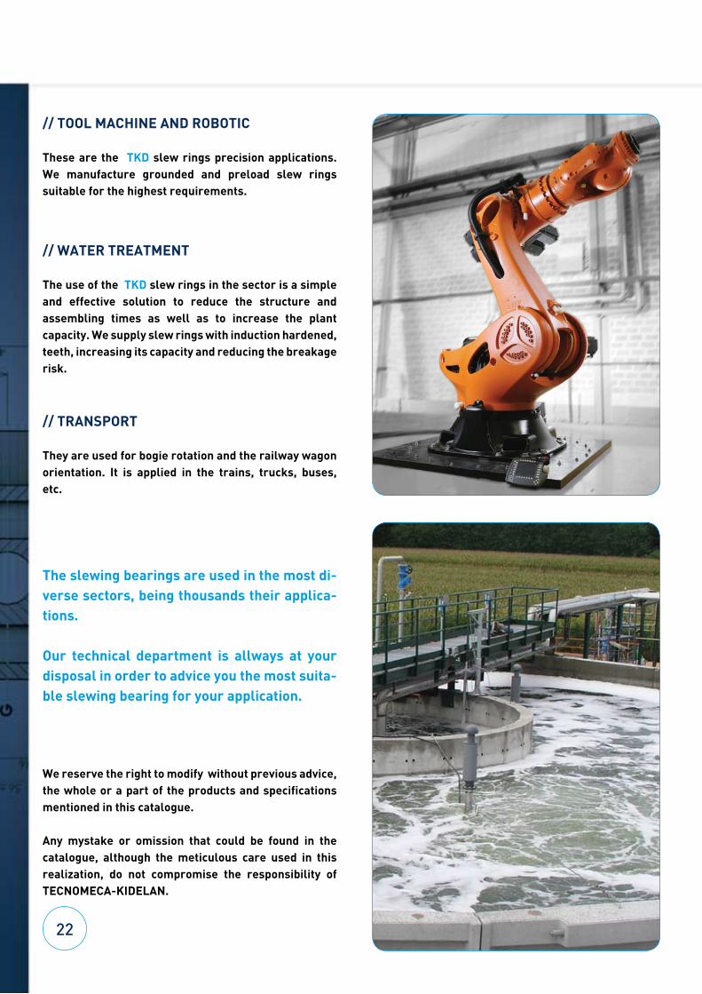
// WATER TREATMENT
The use of the TKD slew rings in the sector is a simple and effective solution to reduce the structure and assembling times as well as to increase the plant capacity. We supply slew rings with induction hardened, teeth, increasing its capacity and reducing the breakage risk.
// TRANSPORT
They are used for bogie rotation and the railway wagon orientation. It is applied in the trains, trucks, buses, etc.
The slewing bearings are used in the most di-verse sectors, being thousands their applica-tions.
Our technical department is allways at your disposal in order to advice you the most suita-ble slewing bearing for your application.
We reserve the right to modify without previous advice, the whole or a part of the products and specifications mentioned in this catalogue.
Any mystake or omission that could be found in the catalogue, although the meticulous care used in this realization, do not compromise the responsibility of TECNOMECA-KIDELAN.
22

Bilbao / Bilbo
Vitoria / Gasteiz
Iruña / Pamplona
DonostiaSan Sebastián
Itziar
Elgoibar
Mondragón
BiarritzA-8 Freeway, Exit 13
// HEAD OFFICE SPAIN
TECNOMECA-KIDELAN, S.A.U.Address: Pol. Industrial Itziar,
Parcela J-1 20.829 Deba (Gipuzkoa - Spain)
Contact: Tel.: +34 943 199 201Fax: +34 943 199 273
E-mail: [email protected]
Web: http://www.tecnomeca-kidelan.com
// SALES OFFICE EUROPE
TECNOMECA-KIDELANAddress: Heidt 1E 42499 Hueckeswagen (Germany)Contact: Tel.: +49 2192 936993
Fax: +49 2192 936992E-mail: [email protected]
Web: http://www.tecnomeca-kidelan.com


![Pillar and wall-mounted slewing jib cranes · Max. load capacity [kg] Electric slewing Pillar-mounted slewing jib cranes Wall-mounted slewing jib cranes Jib type/design Max. outreach](https://img.dokumen.tips/doc/110x75/5b535fa87f8b9ae30b8be93d/pillar-and-wall-mounted-slewing-jib-cranes-max-load-capacity-kg-electric.jpg)