Embed Size (px)
Citation preview

RAPID COMMUNICATIONS
PHYSICAL REVIEW B 87, 100402(R) (2013)
Skyrmion dynamics in multiferroic insulators
Ye-Hua Liu,1 You-Quan Li,1 and Jung Hoon Han2,3,*
1Zhejiang Institute of Modern Physics and Department of Physics, Zhejiang University, Hangzhou 310027, People’s Republic of China2Department of Physics and BK21 Physics Research Division, Sungkyunkwan University, Suwon 440-746, Korea
3Asia Pacific Center for Theoretical Physics, Pohang, Gyeongbuk 790-784, Korea(Received 14 September 2012; revised manuscript received 19 November 2012; published 13 March 2013)
The recent discovery of a Skyrmion crystal phase in an insulating multiferroic compound Cu2OSeO3 callsfor new ways and ideas to manipulate the Skyrmions in the absence of spin transfer torque from the conductionelectrons. It is shown here that the position-dependent electric field, pointed along the direction of the averageinduced dipole moment of the Skyrmion, can induce the Hall motion of the Skyrmion with its velocity orthogonalto the field gradient. Finite Gilbert damping produces longitudinal motion. Inter-Skyrmion interaction leads tothe reduction of the drift speed. We find a rich variety of resonance modes excited by an ac electric field.
DOI: 10.1103/PhysRevB.87.100402 PACS number(s): 75.85.+t, 75.70.Kw, 76.50.+g
Skyrmions are fast becoming common sightings among spi-ral magnets including many of the metallic B20 compounds1–5
and most recently, in a multiferroic insulator Cu2OSeO3.6 Bothspecies of compounds display similar thickness-dependentphase diagrams5,6 despite their completely different electricalproperties, highlighting the generality of the Skyrmion phasein spiral magnets. Along with the ubiquity of Skyrmionmatter comes the challenge of finding a means to control andmanipulate them, in a device-oriented manner akin to effortsin the spintronics community to control the domain wall andvortex motion by electrical current. Spin transfer torque (STT)is a powerful means to induce fast domain-wall motion inmetallic magnets.7,8 Indeed, current-driven Skyrmion rotation9
and collective drift,10 originating from STT, have beendemonstrated recently. Theory of current-induced Skyrmiondynamics has been worked out in Refs. 11–13. In insulatingcompounds such as Cu2OSeO3, however, the STT-drivenmechanism does not work due to the lack of conductionelectrons.
Spiral magnetic order in Cu2OSeO3 is accompanied by afinite electric dipole moment as experimentally demonstratedby Seki et al.14 due to the pd-hybridization mechanism.14–18 Inshort, a given magnetization Si induces electric dipole momentPi with the relation
Pi = λ(S
y
i Szi ,S
zi S
xi ,Sx
i Sy
i
)(1)
through some coupling λ. Each site i corresponds to one cubicunit cell of Cu2OSeO3 with linear dimension a ∼ 8.9 A,and we have normalized Si to have unit magnitude. Thedimension of the coupling constant is therefore [λ] = C m.Formula (1) was recently obtained for Cu2OSeO3 from theGinzburg-Landau symmetry argument18 and appeared in theearlier discussion of another pd-hybridization-induced multi-ferroic insulator, Ba2CoGe2O7.19,20 Although not explicitlymentioned in previous theories,18,20 the same formula isapplicable to the Skyrmion lattice phase as well. In Ref. 14microscopic pd polarizations were added up numericallywithout relying on formula (1) to deduce the dipole momentof the Skyrmion. We have verified, as shown in Fig. 1, thatinsertion of the Skyrmion spin configuration Si in Eq. (1)yields the electric dipole moment distribution that agrees verywell with the numerically obtained profile shown in Fig. 4
of Ref. 14. Taking this agreement a step further, we useEq. (1) to demonstrate that an electric-field gradient can induceSkyrmion motion by coupling efficiently to the Skyrmion’sdipole moment. The proposed mechanism may provide asolid means for manipulating insulating Skyrmions and iscomplementary to the current-driven mechanism12 that workson metallic Skyrmions.
Equation (1) implies the presence of the magnetoelectriccoupling Hamiltonian
HME = −∑
i
Pi · Ei = −λ∑
i
(Ex
i Sy
i Szi + cyclic perm.
),
(2)
in addition to the Heisenberg and Dzyaloshinskii-Moriyaexchange interactions among spins (HHDM) and the Zeemaninteraction with the external magnetic field HZ = −B · ∑
i Si
in Cu2OSeO3. Earlier theoretical studies established thatHHDM + HZ can stabilize the Skyrmion phase under a mod-erate magnetic field.1,21–24 The magnetoelectric HamiltonianHME in essence provides the spin anisotropy by applicationof the electric field. The Landau-Lifshitz-Gilbert (LLG)equation corresponding to H = HHDM + HZ + HME can bereadily derived as Si + (1/h)Si × (δH/δSi) + αSi × Si = 0and solved by numerical integration for some Gilbert dampingconstant α.
In the experiment of Ref. 14, three crystallographicallydistinct orientations were chosen for measuring the magnetic-field-induced polarization. Categorizing the experimental find-ings, the magnetic field and induced Skyrmion dipole momentorientations are, respectively, (I) B‖[001], P = 0, (II) B‖[110],P‖[001], and (III) B‖[111], P‖[111]. In case (I) only a netquadrupole moment is induced on the Skyrmion. In cases(II) and (III) an electric field can be imposed parallel tothe dipole moment, Ei = Ei P (P = P/|P|), to maximizethe magnetoelectric coupling and enhance the electric fieldcontrol. To simplify the subsequent calculation we choose tomake an orthogonal rotation R of the spin axis Si → RS′
i
appearing in Eq. (1) so that the z direction of the new spin S′i
coincides with the B-field orientation in a given setup and its x
direction with the crystallographic [110] since it is orthogonalto all three B-field directions used in the experiment. In each ofthe cases listed above we obtain the magnetoelectric coupling,
100402-11098-0121/2013/87(10)/100402(5) ©2013 American Physical Society

RAPID COMMUNICATIONS
YE-HUA LIU, YOU-QUAN LI, AND JUNG HOON HAN PHYSICAL REVIEW B 87, 100402(R) (2013)
FIG. 1. (Color online) (a) Typical Skyrmion configuration and(b)–(d) the corresponding distribution of dipole density ρD(r) forthree magnetic field orientations used in Ref. 14. For precise definitionof ρD(r) used, see the Supplemental Material (Ref. 25). (b) B‖[001].(c) B‖[110]. (d) B‖[111]. As schematically depicted in (a), theSkyrmion executes a Hall motion in response to the electric fieldgradient.
expressed in the respective rotated spin frames,
H(I)ME = −(λ/2)
∑
i
Ei
([S
y
i
]2 − [Sx
i
]2),
H(II)ME = −(λ/2)
∑
i
Ei
([Sz
i
]2 − [Sx
i
]2), (3)
H(III)ME = −(λ/2
√3)
∑
i
Ei
(3[Sz
i
]2 − 1).
Primes have been dropped from S′i in the above expressions. In
case (I) where there is no net dipole moment for Skyrmions wechose E‖[001] to arrive at a simple magnetoelectric couplingform shown above. In cases (II) and (III) E-field directioncoincides with that of the dipole moment.
Suppose now that the E-field variation is sufficientlyslow on the scale of the lattice constant a to allow therewriting of HME in Eq. (3) in the continuum as HME =−λ(d/a)
∫d2r E(r)ρD(r). It will be assumed that all variables
behave identically along the thickness direction, of lengthd. The dipole density ρD(r), shown in Figs. 1(b)–1(d) forcases (I)–(III), couples to the electric field E(r) in thesame way as the conventional electric charge density doesto the potential field in electromagnetism. The analogy will beuseful when we think about the Skyrmion dynamics under thespatially varying E field. As in Ref. 12 we view the individualSkyrmion as a pointlike object described by the distributionρD(r) = QDNSk
∑j δ(r − rj ), where rj spans the Skyrmion
positions and identical dipole charge QD is assumed for allthe Skyrmions. Explicit definitions of ρD(r) and QD appearin the Supplemental Material,25 while NSk is the number of
spins inside a Skyrmion. The magnetoelectric coupling energyis transformed to the “potential energy” of the collection ofSkyrmion particles,
HME = −λQDNSkd
a
∑
j
E(rj ). (4)
A force acting on the Skyrmion will be Fi = −∇iHME. Inter-Skyrmion interaction is ignored.
The response of Skyrmions to a given force is that of anelectric charge in a strong magnetic field, embodied in theBerry phase action (−2πShQSkd/a3)
∑j
∫dt(rj × rj ) · z,
where QSk is the quantized Skyrmion charge12,26 and S isthe size of spin. An equation of motion follows from thecombination of the Berry phase action and Eq. (4):
vj = λl2Sk
4πSh
QD
QSkz × ∇jE(rj ), (5)
where vj is the j th Skyrmion velocity and l2Sk ≡ NSka
2.Typical speed of the Hall motion can be estimated by replacing|λ∇E| with �Edipole/lSk, where �Edipole is the difference inthe dipolar energy felt at the left and the right edges of theSkyrmion and lSk is its diameter. This way one arrives at thespeed of the Hall motion
vH ∼ 1
4πS
QD
QSk
lSk
tSk, tSk = h
�Edipole, (6)
written, apart from numerical factors, as the linear dimensionof the Skyrmion divided by the “Skyrmion time” tSk as decidedby the dipolar energy difference applied across its length.Adopting experimental input parameters of lSk = 10−7 m, andλ = 10−32 C m from Ref. 14 and using QD = −1 and QSk =−1, we find the velocity vH ∼ 10−6�E[m2/V s], which givesthe estimated drift velocity of 1 mm/s for the field strengthdifference �E = 103 V/m across the Skyrmion. We may aswell estimate the maximum allowed drift velocity by equatingthe dipolar energy difference �Edipole across the Skyrmion tothe exchange energy J , also corresponding to the formationenergy of one Skyrmion.24 The maximum expected velocitythus obtained is enormous, ∼104m/s for J ∼ 1 meV, implyingthat with the right engineering one can achieve rather high Hallvelocity of the Skyrmion. In an encouraging step forward,electric-field control of the Skyrmion lattice orientation in theCu2OSeO3 crystal was recently demonstrated.27
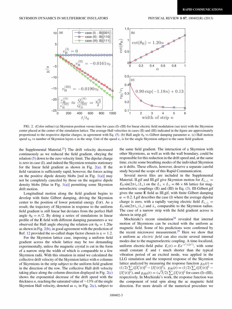
Results of LLG simulation are discussed next. To start,a linear field configuration Eix,iy = aix + b is imposed on arectangular simulation lattice 1 � ix � Lx , 1 � iy � Ly , withboth Lx and Ly much larger than the Skyrmion size. In theabsence of Gilbert damping, a single Skyrmion placed in suchan environment moved along the “equipotential line” in they direction as expected from the guiding-center dynamics ofEq. (5). In cases (II) and (III) the dipole charges obey therelation Q
(II)D /Q
(III)D = √
3/2 as discussed in the SupplementalMaterial,25 and based on Eq. (5) one would expect theirrespective drift velocities to scale with the same ratio. Thisis indeed the case as one can see in Fig. 2. Additionally, thenumerical result of Hall velocity shows excellent agreementwith that calculated by Eq. (5), which is −0.0161v0 forcase (II) and −0.0192v0 for case (III). [Here we have definedt0 = (Sh)/(λa) m2/V and v0 = a/t0. For more details, see
100402-2
RAPID COMMUNICATIONS
SKYRMION DYNAMICS IN MULTIFERROIC INSULATORS PHYSICAL REVIEW B 87, 100402(R) (2013)
0 200 400 600 800 1000−25
−20
−15
−10
−5
0
5
10
t/t0
y/a
v(I)H = 0
v(II)H = −0.0161v0
v(III)H = −0.0190v0
v(II)H
v(III)H
≈ Q(II)D
Q(III)D
=√
32
(a)
0 0.2 0.4 0.6 0.8 10
0.5
1
1.5
α
cot(
θ H)
cot(θH) = 1.20α
(b)
1 2 3 4 5 60.1
0.2
0.3
0.4
0.5
width of strip nv H
/v 1
(c)
0.90 exp(−1.18n) + 0.13
case (I) : B||[001]case (II) : B||[110]case (III): B||[111]
FIG. 2. (Color online) (a) Skyrmion position versus time for cases (I)–(III) for linear electric field modulation (see text) with the Skyrmioncenter placed at the center of the simulation lattice. The average Hall velocities in cases (II) and (III) indicated in the figure are approximatelyproportional to the respective dipolar charges, in agreement with Eq. (5). (b) Hall angle θH vs Gilbert damping parameter α. (c) Hall motionspeed vH vs number of Skyrmion layers n in the strip. Unit of the speed v1 is for the single Skyrmion subject to the same field gradient.
the Supplemental Material.25] The drift velocity decreasedcontinuously as we reduced the field gradient, obeying therelation (5) down to the zero velocity limit. The dipolar chargeis zero in case (I), and indeed the Skyrmion remains stationaryfor the linear field gradient as shown in Fig. 2(a). If thefield variation is sufficiently rapid, however, the forces actingon the positive dipole density blobs [red in Fig. 1(a)] maynot be completely canceled by those on the negative dipoledensity blobs [blue in Fig. 1(a)] permitting some Skyrmiondrift motion.
Longitudinal motion along the field gradient begins todevelop with finite Gilbert damping, driving the Skyrmioncenter to the position of lower potential energy E(r). As aresult, the trajectory of Skyrmion in response to the uniformfield gradient is still linear but deviates from the perfect Hallangle θH = π/2. By doing a series of simulations in linearprofile of the E field with different damping parameters α weobserved the Hall angle obeying the relation cot θH = 1.20α
as shown in Fig. 2(b), in good agreement with the prediction ofRef. 12 provided the so-called shape factor chosen is η = 1.2.
For the Skyrmion lattice case, imposing a uniform fieldgradient across the whole lattice may be too demandingexperimentally, unless the magnetic crystal is cut in the formof a narrow strip the width of which is comparable to a fewSkyrmion radii. With this situation in mind we calculated thecollective drift velocity of the Skyrmion lattice with n columnsof Skyrmions in the strip subject to the uniform field gradientin the direction of the row. The collective Hall drift velocitytaking place along the column direction displayed in Fig. 2(c)shows the exponential decrease of the drift speed with thethickness n, reaching the saturated value of ∼13% of the singleSkyrmion Hall velocity, denoted as v1 in Fig. 2(c), subject to
the same field gradient. The interaction of a Skyrmion withother Skyrmions, as well as with the wall boundary, could beresponsible for this reduction in the drift speed and, at the sametime, excite some breathing modes of the individual Skyrmionas it drifts. These effects, however, deserve a separate carefulstudy beyond the scope of this Rapid Communication.
Several movie files are included in the SupplementalMaterial. II.gif and III.gif give Skyrmion motion for Eix,iy =E0 sin(2πix/Lx) on the Lx × Ly = 66 × 66 lattice for mag-netoelectric couplings (II) and (III) in Eq. (3). III-Gilbert.gifgives the same E field as III.gif, with finite Gilbert dampingα = 0.2. I.gif describes the case (I) where the average dipolarcharge is zero, with a rapidly varying electric field Eix,iy =E0 sin(2πix/λx) and λx comparable to the Skyrmion radius.The case of a narrow strip with the field gradient across isshown in strip.gif.
Mochizuki’s recent simulation28 revealed that internalmotion of Skyrmions can be excited with the uniform acmagnetic field. Some of his predictions were confirmed bythe recent microwave measurement.29 Here we show thata uniform ac electric field can also excite several internalmodes due to the magnetoelectric coupling. A time-localized,uniform electric-field pulse Ei(t) = Ee−t2/(2τ 2), with somesmall constant E and τ much shorter than the typicalvibration period of an excited mode, was applied in theLLG simulation and the temporal response of the Skyrmionlattice analyzed by measuring the response function χ(I)(t) =(1/2)
∑i([S
y
i (t)]2 − [Sxi (t)]2), χ(II)(t) = (1/2)
∑i([S
zi (t)]2 −
[Sxi (t)]2), and χ(III)(t) = (
√3/2)
∑i[S
zi (t)]2 for cases (I)–(III),
respectively. In Mochizuki’s work, the response function wasthe component of total spin along the ac magnetic fielddirection. For more details of the numerical procedure we
100402-3
RAPID COMMUNICATIONS
YE-HUA LIU, YOU-QUAN LI, AND JUNG HOON HAN PHYSICAL REVIEW B 87, 100402(R) (2013)
0
0.2
0.4
0.6
0.8
1
Imχ(ω
)(a
rb.
unit
)
B1
R1
R2
(a)B||z,Bω||x,y
B||z,Bω||z
0 0.05 0.1 0.15 0.2 0.25 0.3 0.35
0
0.2
0.4
0.6
0.8
1
ω/[2π/(Sh/J)]
Imχ(ω
)(a
rb.
unit
)
E
X1X2
B1
B2
(b) case (I) : B||[001],Eω||[001]
case (II) : B||[110],Eω||[001]
case (III): B||[111],Eω||[111]
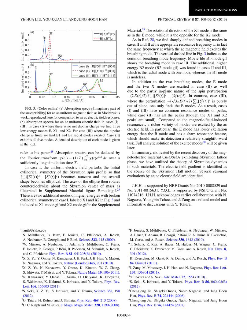
FIG. 3. (Color online) (a) Absorption spectra [imaginary part ofthe susceptibility] for an ac uniform magnetic field as in Mochizuki’swork, reproduced here for comparison to an ac electric field response.(b) Absorption spectra for an ac uniform electric field in cases (I)–(III). In case (I) where there is no net dipolar charge we find threelow-energy modes E, X1, and X2. For case (III) where the dipolarcharge is finite we find B1 and B2 radial modes excited. Case (II)exhibits all five modes. A detailed description of each mode is givenin the text.
refer to his paper.28 Absorption spectra can be deduced bythe Fourier transform χ (ω) = (1/T )
∫ T
0 χ (t)eiωt dt over asufficiently long simulation time T .
In case I, the uniform electric field perturbs the initialcylindrical symmetry of the Skyrmion spin profile so that∑
i([Sxi (t)]2 − [Sy
i (t)]2) becomes nonzero and the overallshape becomes elliptical. The axes of the ellipse then rotatescounterclockwise about the Skyrmion center of mass asillustrated in Supplemental Material figure E-mode.gif.25
There are two additional modes of higher energies with brokencylindrical symmetry in case I, labeled X1 and X2 in Fig. 3 andincluded as X1-mode.gif and X2-mode.gif in the Supplemental
Material.25 The rotational direction of the X1 mode is the sameas in the E mode, while it is the opposite for the X2 mode.
As in Ref. 28, we find sharply defined breathing modes incases II and III at the appropriate resonance frequency ω; in factthe same frequency at which the ac magnetic field excites thebreathing mode. The vertical dashed line in Fig. 3 indicates thecommon breathing mode frequency. Movie file B1-mode.gifshows the breathing mode in case III. The additional, higherenergy B2 mode (B2-mode.gif) was found in cases II and III,which is the radial mode with one node, whereas the B1 modeis nodeless.
In addition to the two breathing modes, the E modeand the two X modes are excited in case (II) as welldue to the partly in-plane nature of the spin perturbation−(λE(t)/2)
∑i([S
zi (t)]2 − [Sx
i (t)]2). In contrast, case (III),where the perturbation −(
√3λE(t)/2)
∑i[S
zi (t)]2 is purely
out of plane, one only finds the B modes. As a result, cases(I) and (III) have no common resonance modes or peaks,while case (II) has all the peaks (though the X1 and X2peaks are small). Compared to the magnetic-field-inducedresonances, a richer variety of modes are excited by the acelectric field. In particular, the E mode has lower excitationenergy than the B mode and has a sharp resonance feature,which should make its detection a relatively straightforwardtask. Full analytic solution of the excited modes30 will be givenlater.
In summary, motivated by the recent discovery of the mag-netoelectric material Cu2OSeO3 exhibiting Skyrmion latticephase, we have outlined the theory of Skyrmion dynamicsin such materials. The electric field gradient is identified asthe source of the Skyrmion Hall motion. Several resonantexcitations by an ac electric field are identified.
J.H.H. is supported by NRF Grants No. 2010-0008529 andNo. 2011-0015631. Y.Q.L. is supported by NSFC Grant No.11074216. J.H.H. acknowledges earlier collaboration with N.Nagaosa, Youngbin Tchoe, and J. Zang on a related model andinformative discussions with Y. Tokura.
*[email protected]. Muhlbauer, B. Binz, F. Jonietz, C. Pfleiderer, A. Rosch,A. Neubauer, R. Georgii, and P. Boni, Science 323, 915 (2009).
2W. Munzer, A. Neubauer, T. Adams, S. Muhlbauer, C. Franz,F. Jonietz, R. Georgii, P. Boni, B. Pedersen, M. Schmidt, A. Rosch,and C. Pfleiderer, Phys. Rev. B 81, 041203(R) (2010).
3X. Z. Yu, Y. Onose, N. Kanazawa, J. H. Park, J. H. Han, Y. Matsui,N. Nagaosa, and Y. Tokura, Nature (London) 465, 901 (2010).
4X. Z. Yu, N. Kanazawa, Y. Onose, K. Kimoto, W. Z. Zhang,S. Ishiwata, Y. Matsui, and Y. Tokura, Nature Mater. 10, 106 (2011).
5N. Kanazawa, Y. Onose, T. Arima, D. Okuyama, K. Ohoyama,S. Wakimoto, K. Kakurai, S. Ishiwata, and Y. Tokura, Phys. Rev.Lett. 106, 156603 (2011).
6S. Seki, X. Z. Yu, S. Ishiwata, and Y. Tokura, Science 336, 198(2012).
7G. Tatara, H. Kohno, and J. Shibata, Phys. Rep. 468, 213 (2008).8D. C. Ralph and M. Stiles, J. Magn. Magn. Mater. 320, 1190 (2008).
9F. Jonietz, S. Muhlbauer, C. Pfleiderer, A. Neubauer, W. Munzer,A. Bauer, T. Adams, R. Georgii, P. Boni, R. A. Duine, K. Everschor,M. Garst, and A. Rosch, Science 330, 1648 (2010).
10T. Schulz, R. Ritz, A. Bauer, M. Halder, M. Wagner, C. Franz,C. Pfleiderer, K. Everschor, M. Garst, and A. Rosch, Nat. Phys. 8,301 (2012).
11K. Everschor, M. Garst, R. A. Duine, and A. Rosch, Phys. Rev. B84, 064401 (2011).
12J. Zang, M. Mostovoy, J. H. Han, and N. Nagaosa, Phys. Rev. Lett.107, 136804 (2011).
13Y. Tokura and S. Seki, Adv. Mater. 22, 1554 (2010).14S. Seki, S. Ishiwata, and Y. Tokura, Phys. Rev. B 86, 060403(R)
(2012).15Chenglong Jia, Shigeki Onoda, Naoto Nagaosa, and Jung Hoon
Han, Phys. Rev. B 74, 224444 (2006).16Chenglong Jia, Shigeki Onoda, Naoto Nagaosa, and Jung Hoon
Han, Phys. Rev. B 76, 144424 (2007).
100402-4

RAPID COMMUNICATIONS
SKYRMION DYNAMICS IN MULTIFERROIC INSULATORS PHYSICAL REVIEW B 87, 100402(R) (2013)
17Taka-hisa Arima, J. Phys. Soc. Jpn. 76, 073702 (2007).18M. Belesi, I. Rousochatzakis, M. Abid, U. K. Roßler,
H. Berger, and J.-Ph. Ansermet, Phys. Rev. B 85, 224413(2012).
19H. Murakawa, Y. Onose, S. Miyahara, N. Furukawa, and Y. Tokura,Phys. Rev. Lett. 105, 137202 (2010).
20Judit Romhanyi, Miklos Lajko, and Karlo Penc, Phys. Rev. B 84,224419 (2011).
21A. N. Bogdanov and D. A. Yablonskii, Sov. Phys. JETP 68, 101(1989); A. Bogdanov and A. Hubert, J. Magn. Magn. Mater. 138,255 (1994).
22U. K. Roßler, A. N. Bogdanov, and C. Pfleiderer, Nature (London)442, 797 (2006).
23Su Do Yi, Shigeki Onoda, Naoto Nagaosa, and Jung Hoon Han,Phys. Rev. B 80, 054416 (2009).
24Jung Hoon Han, Jiadong Zang, Zhihua Yang, Jin-Hong Park, andNaoto Nagaosa, Phys. Rev. B 82, 094429 (2010).
25See Supplemental Material at http://link.aps.org/supplemental/10.1103/PhysRevB.87.100402 for details of numerical simulation.
26Michael Stone, Phys. Rev. B 53, 16573 (1996).27J. S. White, I. Levatic, A. A. Omrani, N. Egetenmeyer, K. Prsa,
I. Zivkovic, J. L. Gavilano, J. Kohlbrecher, M. Bartkowiak,H. Berger, and H. M. Rønnow, J. Phys.: Condens. Matter 24, 432201(2012).
28Masahito Mochizuki, Phys. Rev. Lett. 108, 017601 (2012).29Y. Onose, Y. Okamura, S. Seki, S. Ishiwata, and Y. Tokura, Phys.
Rev. Lett. 109, 037603 (2012).30Olga Petrova and Oleg Tchernyshyov, Phys. Rev. B 84,
214433 (2011); Imam Makhfudz, Benjamin Kruger, and OlegTchernyshyov, Phys. Rev. Lett. 109, 217201 (2012).
100402-5
![Evolution of two-dimensional antiferromagnetism with ... -- multiferroic... · 2CoGe 2O 7 were grown by floating-zone technique and characterized in previous stud-ies [9,11,13,18]](https://img.dokumen.tips/doc/110x75/5c68e5da09d3f2e4258c11ee/evolution-of-two-dimensional-antiferromagnetism-with-multiferroic.jpg)


![arXiv:1702.04158v4 [cond-mat.str-el] 21 Nov 2017 · 2017-11-22 · Direct observation of spin-quadrupolar excitations in Sr 2CoGe 2O 7 by high eld ESR Mitsuru Akaki,1, Daichi Yoshizawa,](https://img.dokumen.tips/doc/110x75/5e414f0b4cdc661eeb58c01c/arxiv170204158v4-cond-matstr-el-21-nov-2017-2017-11-22-direct-observation.jpg)


