Embed Size (px)
Citation preview
SISTEMA DI LUBRIFICAZIONECENTRALIZZATA
CENTRALIZED LUBRICATION SYSTEM
SISTEMA DOPPIA LINEADUAL LINE SYSTEM

�
DUAL LINE SYSTEM
SISTEMA DI LUBRIFICAZIONECENTRALIZZATA
CENTRALIZED LUBRICATION SYSTEM
SISTEMA DOPPIA LINEADUAL LINE SYSTEM
Cat. Code 3320950 - 06/2007
��
SISTEMA DOPPIA LINEA
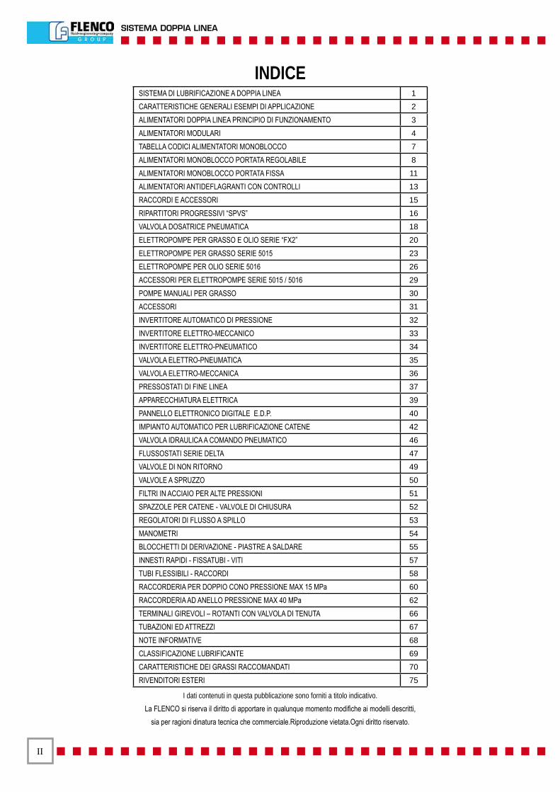
INDICE
I dati contenuti in questa pubblicazione sono forniti a titolo indicativo.La FLENCO si riserva il diritto di apportare in qualunque momento modifiche ai modelli descritti,
sia per ragioni dinatura tecnica che commerciale.Riproduzione vietata.Ogni diritto riservato.
SISTEMA DI LUBRIFICAZIONE A DOPPIA LINEA 1
CARATTERISTICHE GENERALI ESEMPI DI APPLICAZIONE 2
ALIMENTATORI DOPPIA LINEA PRINCIPIO DI FUNZIONAMENTO 3
ALIMENTATORI MODULARI 4
TABELLA CODICI ALIMENTATORI MONOBLOCCO 7
ALIMENTATORI MONOBLOCCO PORTATA REGOLABILE 8
ALIMENTATORI MONOBLOCCO PORTATA FISSA 11
ALIMENTATORI ANTIDEFLAGRANTI CON CONTROLLI 13
RACCORDI E ACCESSORI 15
RIPARTITORI PROGRESSIVI “SPVS” 16
VALVOLA DOSATRICE PNEUMATICA 18
ELETTROPOMPE PER GRASSO E OLIO SERIE “FX2” 20
ELETTROPOMPE PER GRASSO SERIE 5015 23
ELETTROPOMPE PER OLIO SERIE 5016 26
ACCESSORI PER ELETTROPOMPE SERIE 5015 / 5016 29
POMPE MANUALI PER GRASSO 30
ACCESSORI 31
INVERTITORE AUTOMATICO DI PRESSIONE 32
INVERTITORE ELETTRO-MECCANICO 33
INVERTITORE ELETTRO-PNEUMATICO 34
VALVOLA ELETTRO-PNEUMATICA 35
VALVOLA ELETTRO-MECCANICA 36
PRESSOSTATI DI FINE LINEA 37
APPARECCHIATURA ELETTRICA 39
PANNELLO ELETTRONICO DIGITALE E.D.P. 40
IMPIANTO AUTOMATICO PER LUBRIFICAZIONE CATENE 42
VALVOLA IDRAULICA A COMANDO PNEUMATICO 46
FLUSSOSTATI SERIE DELTA 47
VALVOLE DI NON RITORNO 49
VALVOLE A SPRUZZO 50
FILTRI IN ACCIAIO PER ALTE PRESSIONI 51
SPAZZOLE PER CATENE - VALVOLE DI CHIUSURA 52
REGOLATORI DI FLUSSO A SPILLO 53
MANOMETRI 54
BLOCCHETTI DI DERIVAZIONE - PIASTRE A SALDARE 55
INNESTI RAPIDI - FISSATUBI - VITI 57
TUBI FLESSIBILI - RACCORDI 58
RACCORDERIA PER DOPPIO CONO PRESSIONE MAX 15 MPa 60
RACCORDERIA AD ANELLO PRESSIONE MAX 40 MPa 62
TERMINALI GIREVOLI – ROTANTI CON VALVOLA DI TENUTA 66
TUBAZIONI ED ATTREZZI 67
NOTE INFORMATIVE 68
CLASSIFICAZIONE LUBRIFICANTE 69
CARATTERISTICHE DEI GRASSI RACCOMANDATI 70
RIVENDITORI ESTERI 75
���
DUAL LINE SYSTEM
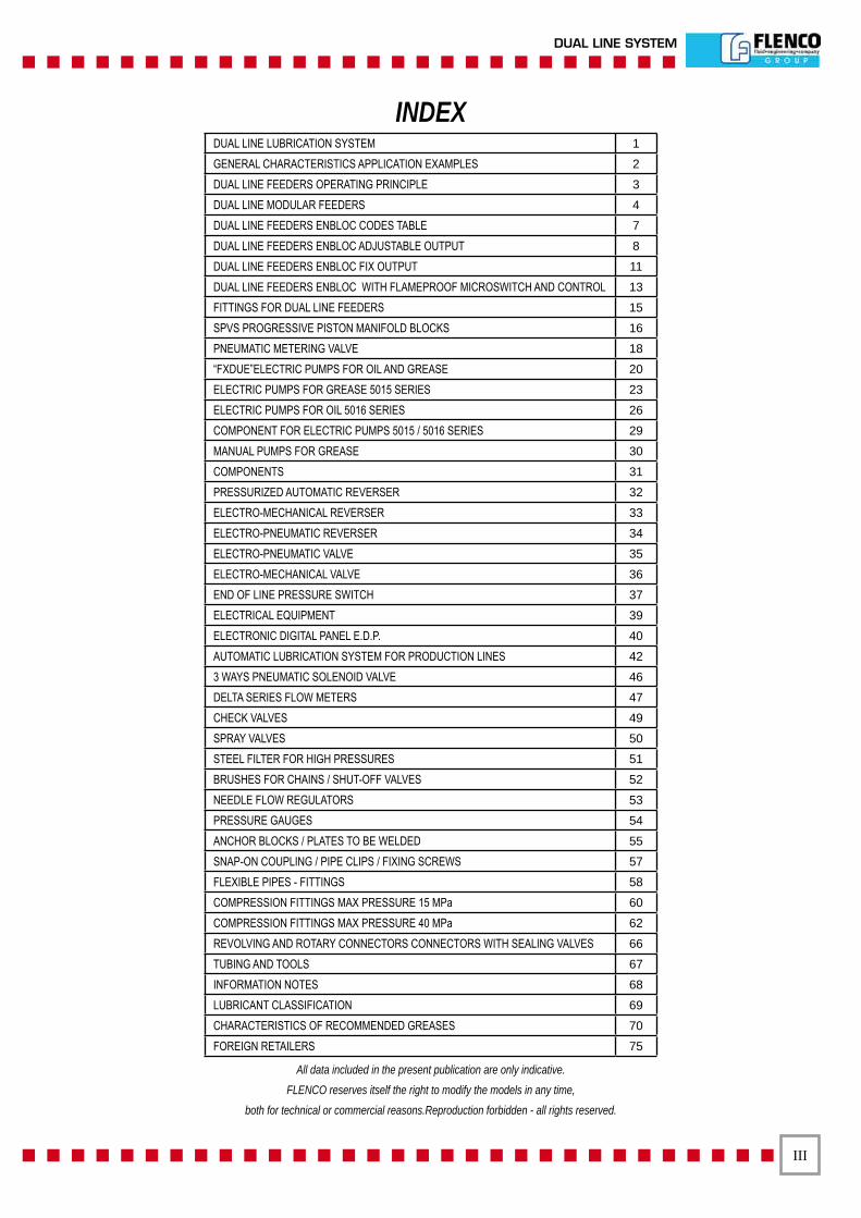
DUAL LINE LUBRICATION SYSTEM 1
GENERAL CHARACTERISTICS APPLICATION EXAMPLES 2
DUAL LINE FEEDERS OPERATING PRINCIPLE 3
DUAL LINE MODULAR FEEDERS 4
DUAL LINE FEEDERS ENBLOC CODES TABLE 7
DUAL LINE FEEDERS ENBLOC ADJUSTABLE OUTPUT 8
DUAL LINE FEEDERS ENBLOC FIX OUTPUT 11
DUAL LINE FEEDERS ENBLOC WITH FLAMEPROOF MICROSWITCH AND CONTROL 13
FITTINGS FOR DUAL LINE FEEDERS 15
SPVS PROGRESSIVE PISTON MANIFOLD BLOCKS 16
PNEUMATIC METERING VALVE 18
“FXDUE”ELECTRIC PUMPS FOR OIL AND GREASE 20
ELECTRIC PUMPS FOR GREASE 5015 SERIES 23
ELECTRIC PUMPS FOR OIL 5016 SERIES 26
COMPONENT FOR ELECTRIC PUMPS 5015 / 5016 SERIES 29
MANUAL PUMPS FOR GREASE 30
COMPONENTS 31
PRESSURIZED AUTOMATIC REVERSER 32
ELECTRO-MECHANICAL REVERSER 33
ELECTRO-PNEUMATIC REVERSER 34
ELECTRO-PNEUMATIC VALVE 35
ELECTRO-MECHANICAL VALVE 36
END OF LINE PRESSURE SWITCH 37
ELECTRICAL EQUIPMENT 39
ELECTRONIC DIGITAL PANEL E.D.P. 40
AUTOMATIC LUBRICATION SYSTEM FOR PRODUCTION LINES 42
3 WAYS PNEUMATIC SOLENOID VALVE 46
DELTA SERIES FLOW METERS 47
CHECK VALVES 49
SPRAY VALVES 50
STEEL FILTER FOR HIGH PRESSURES 51
BRUSHES FOR CHAINS / SHUT-OFF VALVES 52
NEEDLE FLOW REGULATORS 53
PRESSURE GAUGES 54
ANCHOR BLOCKS / PLATES TO BE WELDED 55
SNAP-ON COUPLING / PIPE CLIPS / FIXING SCREWS 57
FLEXIBLE PIPES - FITTINGS 58
COMPRESSION FITTINGS MAX PRESSURE 15 MPa 60
COMPRESSION FITTINGS MAX PRESSURE 40 MPa 62
REVOLVING AND ROTARY CONNECTORS CONNECTORS WITH SEALING VALVES 66
TUBING AND TOOLS 67
INFORMATION NOTES 68
LUBRICANT CLASSIFICATION 69
CHARACTERISTICS OF RECOMMENDED GREASES 70
FOREIGN RETAILERS 75
All data included in the present publication are only indicative.FLENCO reserves itself the right to modify the models in any time,
both for technical or commercial reasons.Reproduction forbidden - all rights reserved.
INDEX

�V
SISTEMA DOPPIA LINEA
CODICE INDICE NUMERICO PAGINA CODE NUMERICAL INDEX PAGE
3304001 ÷ 3304003 583304004 ÷ 3304005 593304006 ÷ 3304008 583304012 ÷ 3304018 585010001 ÷ 5010004 7-95010006 ÷ 5010009 145010010 ÷ 5010013 7-9-145010014 ÷ 5010017 7-85010019 ÷ 5010022 7-105010024 ÷ 5010027 7-85010040 ÷ 5010043 7-95010045 ÷ 5010048 7-85010051 ÷ 5010054 7-95010064 135010070 ÷ 5010073 7-125010074 ÷ 5010077 7-85010080 ÷ 5010083 7-125010084 ÷ 5010087 7-105010090 ÷ 5010098 65010099 ÷ 5010172 65010101 ÷ 5010104 7-125010110 ÷ 5010113 7-125010114 5010117 7-115010119 ÷ 5010122 7-125010124 ÷ 5010127 115010129 ÷ 5010132 7-115010134 ÷ 5010137 7-115010139 ÷ 5010142 7-125010143 ÷ 5010146 105011086 395015016 ÷ 5015017 25 5015050 ÷ 5015052 255015055 ÷ 5015062 255015215 ÷ 5015216 255015220 ÷ 5015225 215015230 ÷ 5015235 215015260 ÷ 5015261 215015263 ÷ 5015264 215016001 ÷ 5016006 22 5016011 ÷ 5016016 28 5016021 ÷ 5016026 22 5020001 ÷ 5020002 30 5020005 30 5054001 37 5054002 38 5057004 25-28-325057006 ÷ 5057008 345057009 25-33
CODICE INDICE NUMERICO PAGINA CODE NUMERICAL INDEX PAGE
5057010 345057011 33 5057017 ÷ 5057019 36 5057025 ÷ 5057027 365057031 ÷ 5057033 365060010 ÷ 5060013 355060015 ÷ 5060018 355060020 ÷ 5060023 355060025 ÷ 5060028 355062002 ÷ 5062013 495213005 ÷ 5213007 145213009 185213010 146012030 ÷ 6012033 406015050 ÷ 6015052 256015055 6015057 256016010 ÷ 6016011 286016014 286016020 ÷ 6016021 286016024 286067374 ÷ 6067375 457036001 ÷ 7036002 577036005 7036008 577036016 ÷ 7036023 577040001 487040011 ÷ 7040025 477050013 ÷ 7050015 297050014 25-287050018 ÷ 7050019 297052001 ÷ 7052009 487052032 ÷ 7052037 537060004 ÷ 7060008 467069002 187076007 ÷ 7076012 517076023 ÷ 7076028 517076035 ÷ 7076040 517093001 ÷ 7093023 607093007 67093012 67093015 67093030 ÷ 7093031 607094001 ÷ 7094016 617097001 ÷ 7097007 607098001 ÷ 7098006 617102001 ÷ 7102021 647102022 ÷ 7102025 657102026 7102038 647103012 ÷ 7103014 66
V
DUAL LINE SYSTEM
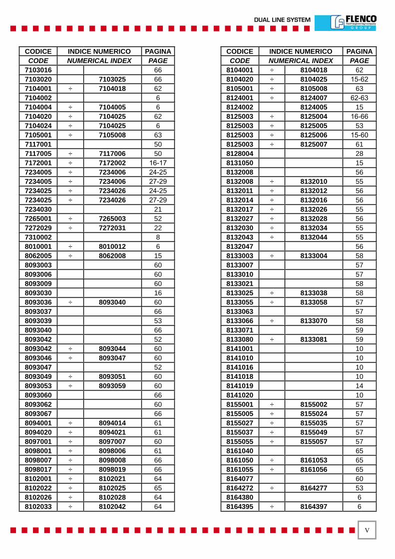
CODICE INDICE NUMERICO PAGINA CODE NUMERICAL INDEX PAGE
7103016 667103020 7103025 667104001 ÷ 7104018 627104002 67104004 ÷ 7104005 67104020 ÷ 7104025 627104024 ÷ 7104025 67105001 ÷ 7105008 637117001 507117005 ÷ 7117006 507172001 ÷ 7172002 16-177234005 ÷ 7234006 24-257234005 ÷ 7234006 27-297234025 ÷ 7234026 24-257234025 ÷ 7234026 27-297234030 217265001 ÷ 7265003 527272029 ÷ 7272031 227310002 88010001 ÷ 8010012 68062005 ÷ 8062008 158093003 608093006 608093009 608093030 168093036 ÷ 8093040 608093037 668093039 538093040 668093042 528093042 ÷ 8093044 608093046 ÷ 8093047 608093047 528093049 ÷ 8093051 608093053 ÷ 8093059 608093060 668093062 608093067 668094001 ÷ 8094014 618094020 ÷ 8094021 618097001 ÷ 8097007 608098001 ÷ 8098006 618098007 ÷ 8098008 668098017 ÷ 8098019 668102001 ÷ 8102021 648102022 ÷ 8102025 658102026 ÷ 8102028 648102033 ÷ 8102042 64
CODICE INDICE NUMERICO PAGINA CODE NUMERICAL INDEX PAGE
8104001 ÷ 8104018 628104020 ÷ 8104025 15-628105001 ÷ 8105008 638124001 ÷ 8124007 62-638124002 8124005 158125003 ÷ 8125004 16-668125003 ÷ 8125005 538125003 ÷ 8125006 15-608125003 ÷ 8125007 618128004 288131050 158132008 568132008 ÷ 8132010 558132011 ÷ 8132012 568132014 ÷ 8132016 568132017 ÷ 8132026 558132027 ÷ 8132028 568132030 ÷ 8132034 558132043 ÷ 8132044 558132047 568133003 ÷ 8133004 588133007 578133010 578133021 588133025 ÷ 8133038 588133055 ÷ 8133058 578133063 578133066 ÷ 8133070 588133071 598133080 ÷ 8133081 598141001 108141010 108141016 108141018 108141019 148141020 108155001 ÷ 8155002 578155005 ÷ 8155024 578155027 ÷ 8155035 578155037 ÷ 8155049 578155055 ÷ 8155057 578161040 658161050 ÷ 8161053 658161055 ÷ 8161056 658164077 608164272 ÷ 8164277 538164380 68164395 ÷ 8164397 6
V�
SISTEMA DOPPIA LINEA
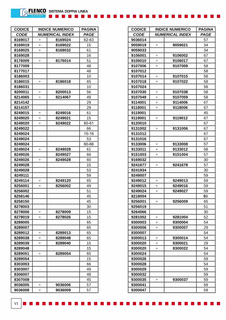
CODICE INDICE NUMERICO PAGINA CODE NUMERICAL INDEX PAGE
8169017 ÷ 8169024 62-638169019 ÷ 8169022 158169025 ÷ 8169032 618169028 168176009 ÷ 8176014 518177009 488177017 488186003 108186015 ÷ 8186018 658186031 108200011 ÷ 8200013 568214065 ÷ 8214067 498214142 298214157 298249015 ÷ 8249016 618249020 ÷ 8249021 158249020 ÷ 8249022 60-618249022 668249024 15-168249024 538249024 60-668249024 ÷ 8249028 618249026 8249027 668249026 ÷ 8249028 608249028 158249028 538249111 598249114 ÷ 8249120 658256001 ÷ 8256002 498256002 518258146 458258150 458278003 308278006 ÷ 8278009 158278019 ÷ 8278026 158289005 658289007 658289012 ÷ 8289013 658289038 ÷ 8289048 658289039 ÷ 8289040 158289048 158289051 ÷ 8289054 658289054 158303003 668303007 498306007 488307008 459036005 ÷ 9036006 579036008 ÷ 9036009 57
CODICE INDICE NUMERICO PAGINA CODE NUMERICAL INDEX PAGE
9036014 579059019 ÷ 9059021 349059033 349106001 ÷ 9106002 679106010 ÷ 9106017 679107006 ÷ 9107009 589107012 589107014 ÷ 9107015 589107018 ÷ 9107022 589107024 589107030 ÷ 9107038 589107049 ÷ 9107059 589114001 ÷ 9114006 679118001 ÷ 9118006 679119001 459119001 ÷ 9119012 679120010 679131002 ÷ 9131006 679131012 679131016 679133006 ÷ 9133008 579133011 ÷ 9133012 589151003 ÷ 9151004 579169032 309241677 ÷ 9241678 579241934 309249007 599249012 ÷ 9249013 599249015 ÷ 9249016 599249024 ÷ 9249027 598218004 599256001 ÷ 9256009 659256019 519264066 309281002 ÷ 9281004 529300003 ÷ 9300004 549300006 ÷ 9300007 299300007 549300013 ÷ 9300014 549300020 ÷ 9300021 299300020 ÷ 9300022 549300024 549300026 599300028 549300029 599300032 599300035 ÷ 9300037 599300041 599300047 59

V��
DUAL LINE SYSTEM


�
DUAL LINE SYSTEM
SISTEMIDI LUBRIFICAZIONE
A DOPPIA LINEA
DUAL LINELUBRICATION
SYSTEM

�
SISTEMA DOPPIA LINEA
SISTEMA DI LUBRIFICAZIONE A DOPPIA LINEA DUAL LINE LUBRICATION SYSTEM
CARATTERISTICHE GENERALI:
I sistemi di lubrificazione a DOPPIA LINEA trovano il loro im-piego normalmente negli impianti di grandi dimensioni, in ac-ciaieria, nei carri-ponte, gru da banchina, cartiere, cementifici e presse. La struttura dei dosatori è stata studiata apposita-mente per l’impiego di grasso (anche se l’uso di olio è co-munque possibile) e gli impianti sono dimensionati per poter raggiungere pressioni di 20/40 MPa (ma se l’impianto lo per-mette anche 50 MPa) ed estensioni delle tubazioni superiori ai 70 metri (fig. 1). Si può intuire che gli impianti a DOPPIA LI-NEA saranno generalmente alimentati da pompe ad altissime prestazioni come le elettropompe della serie FXDUE e 5015 o eventualmente da grosse pompe pneumatiche o manuali. Inoltre, in particolar modo quando si usano elettropompe, sa-ranno necessarie apparecchiature elettriche per il comando ed il controllo dell’impianto.
Fig. 2: impianto di lubrificazione a DOPPIA LINEA (questi impianti a comando manuale hanno di norma un numero contenuto di punti da servire: l’esempio dello schema sopra-riportato rappresenta un impianto di medie dimensioni. Tale soluzione che non necessita di apparecchiatura di controllo è molto diffusa).
Per questo motivo gli impianti a DOPPIA LINEA sono sicura-mente quelli più impegnativi dal punto di vista impiantistico, pur risultando allo stesso tempo di sicura affidabilità e robu-stezza (vedi figure 1 e 2).
GENERAL CHARACTERISTICS:
DUAL LINE lubrication systems are normally used in large plants, such as steel mills, bridge cranes, quarry cranes, pa-per mills, cement factories, pressing machines and large ma-chine tools. The distributors have been specifically designed for use primarily with grease (oil can be used). Dual Line sy-stems reach working pressures of 20-40 MPa (2900 to 5800 PSI) with total piping lengths of over 70 meters (‘231 ft) (Figu-re 2) DUAL LINE systems generally utilize high-performance pumps like FXDUE and 5015 series electric pumps as well as large pneumatic or manual pumps. In addition, and especially with electric pumps, special electrical devices must be used to command and control most systems.
Figure 2: DUAL LINE lubrication system (this kind of manual driven systems has normally a reduced number of points to be served: the example of the diagram shows a medium si-zed one. This solution, which does not require controlling de-vices is extremely widespread).
For this reason DUAL LINE systems are the most demanding to be installed. Nevertheless they are at the same time extremely reliable and stout (see figures 1 and 2).
Fig. �
Fig. �
�
DUAL LINE SYSTEM
ALIMENTATORI LINEA DOPPIA DUAL LINE FEEDERS
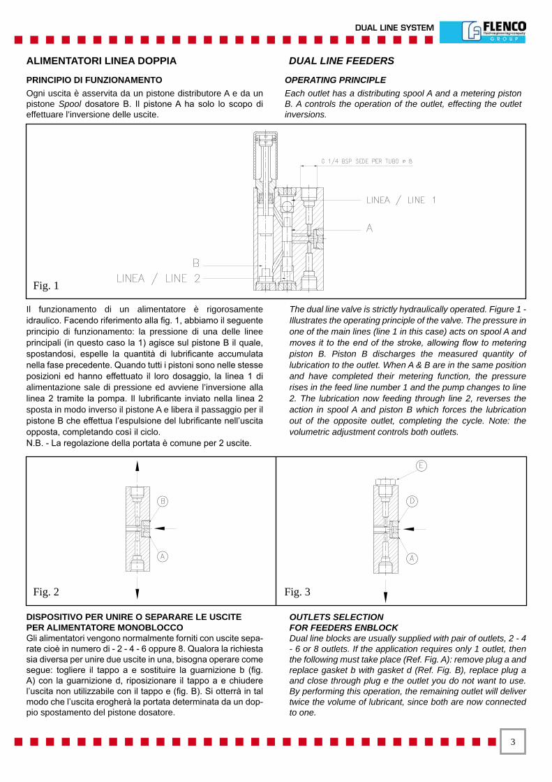
PRINCIPIO DI FUNZIONAMENTOOgni uscita è asservita da un pistone distributore A e da un pistone Spool dosatore B. Il pistone A ha solo lo scopo di effettuare l’inversione delle uscite.
OPERATING PRINCIPLEEach outlet has a distributing spool A and a metering piston B. A controls the operation of the outlet, effecting the outlet inversions.
Il funzionamento di un alimentatore è rigorosamente idraulico. Facendo riferimento alla fig. 1, abbiamo il seguente principio di funzionamento: la pressione di una delle linee principali (in questo caso la 1) agisce sul pistone B il quale, spostandosi, espelle la quantità di lubrificante accumulata nella fase precedente. Quando tutti i pistoni sono nelle stesse posizioni ed hanno effettuato il loro dosaggio, la linea 1 di alimentazione sale di pressione ed avviene l’inversione alla linea 2 tramite la pompa. Il lubrificante inviato nella linea 2 sposta in modo inverso il pistone A e libera il passaggio per il pistone B che effettua l’espulsione del lubrificante nell’uscita opposta, completando così il ciclo. N.B. - La regolazione della portata è comune per 2 uscite.
The dual line valve is strictly hydraulically operated. Figure 1 - Illustrates the operating principle of the valve. The pressure in one of the main lines (line 1 in this case) acts on spool A and moves it to the end of the stroke, allowing flow to metering piston B. Piston B discharges the measured quantity of lubrication to the outlet. When A & B are in the same position and have completed their metering function, the pressure rises in the feed line number 1 and the pump changes to line 2. The lubrication now feeding through line 2, reverses the action in spool A and piston B which forces the lubrication out of the opposite outlet, completing the cycle. Note: the volumetric adjustment controls both outlets.
DISPOSITIVO PER UNIRE O SEPARARE LE USCITEPER ALIMENTATORE MONOBLOCCO Gli alimentatori vengono normalmente forniti con uscite sepa-rate cioè in numero di - 2 - 4 - 6 oppure 8. Qualora la richiesta sia diversa per unire due uscite in una, bisogna operare come segue: togliere il tappo a e sostituire la guarnizione b (fig. A) con la guarnizione d, riposizionare il tappo a e chiudere l’uscita non utilizzabile con il tappo e (fig. B). Si otterrà in tal modo che l’uscita erogherà la portata determinata da un dop-pio spostamento del pistone dosatore.
OUTLETS SELECTIONFOR FEEDERS ENBLOCKDual line blocks are usually supplied with pair of outlets, 2 - 4 - 6 or 8 outlets. If the application requires only 1 outlet, then the following must take place (Ref. Fig. A): remove plug a and replace gasket b with gasket d (Ref. Fig. B), replace plug a and close through plug e the outlet you do not want to use. By performing this operation, the remaining outlet will deliver twice the volume of lubricant, since both are now connected to one.
Fig. �
Fig. � Fig. �
�
SISTEMA DOPPIA LINEA
ALIMENTATORI MODULARI LINEA DOPPIA DUAL LINE MODULAR FEEDERS
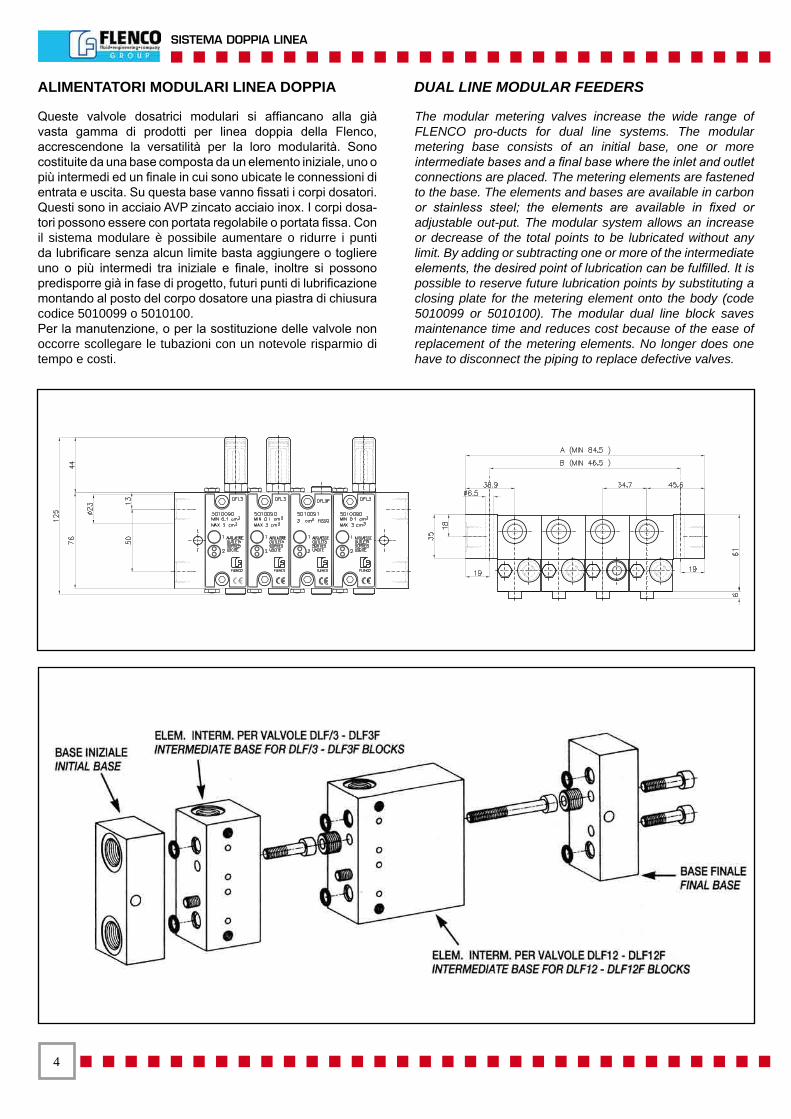
Queste valvole dosatrici modulari si affiancano alla già vasta gamma di prodotti per linea doppia della Flenco, accrescendone la versatilità per la loro modularità. Sono costituite da una base composta da un elemento iniziale, uno o più intermedi ed un finale in cui sono ubicate le connessioni di entrata e uscita. Su questa base vanno fissati i corpi dosatori. Questi sono in acciaio AVP zincato acciaio inox. I corpi dosa-tori possono essere con portata regolabile o portata fissa. Con il sistema modulare è possibile aumentare o ridurre i punti da lubrificare senza alcun limite basta aggiungere o togliere uno o più intermedi tra iniziale e finale, inoltre si possono predisporre già in fase di progetto, futuri punti di lubrificazione montando al posto del corpo dosatore una piastra di chiusura codice 5010099 o 5010100.Per la manutenzione, o per la sostituzione delle valvole non occorre scollegare le tubazioni con un notevole risparmio di tempo e costi.
The modular metering valves increase the wide range of FLENCO pro-ducts for dual line systems. The modular metering base consists of an initial base, one or more intermediate bases and a final base where the inlet and outlet connections are placed. The metering elements are fastened to the base. The elements and bases are available in carbon or stainless steel; the elements are available in fixed or adjustable out-put. The modular system allows an increase or decrease of the total points to be lubricated without any limit. By adding or subtracting one or more of the intermediate elements, the desired point of lubrication can be fulfilled. It is possible to reserve future lubrication points by substituting a closing plate for the metering element onto the body (code 5010099 or 5010100). The modular dual line block saves maintenance time and reduces cost because of the ease of replacement of the metering elements. No longer does one have to disconnect the piping to replace defective valves.
�
DUAL LINE SYSTEM
ALIMENTATORI MODULARI LINEA DOPPIA DUAL LINE MODULAR FEEDERS
TECHNICAL CHARACTERISTICS:
- Inlet working pressure:min. 3 MPa (435 PSI), max 40 MPa (5800 PSI) - Oil viscosity: min. 15 cSt - Max grease viscosity: 220 ASTM NLGI 3 - Working cycles: 100/min. - Working temperature: -30 +80° C - Output adjustment: 0,1-24 cm3 - Connections: inlet Rp 3/8 UNI-ISO 7/1 - NPTF,output Rp 1/4 UNI-ISO 7/1 - NPTF
CARATTERISTICHE TECNICHE:
- Pressione d’esercizio in entrata:min. 3 MPa, max 40 MPa - Viscosità olio: min. 15 cSt - Max densità grasso: 220 ASTM NLGI 3 - Cicli di lavoro: 100 al minuto -Temperatura di esercizio: -30 +80° C - Regolazione portata: 0,1-24 cm3 - Connessioni: ingresso Rp 3/8 UNI-ISO 7/1 - NPTF,uscita Rp 1/4 UNI-ISO 7/1 - NPTF
DISPOSITIVO PER UNIRE O SEPARARE LE USCITE
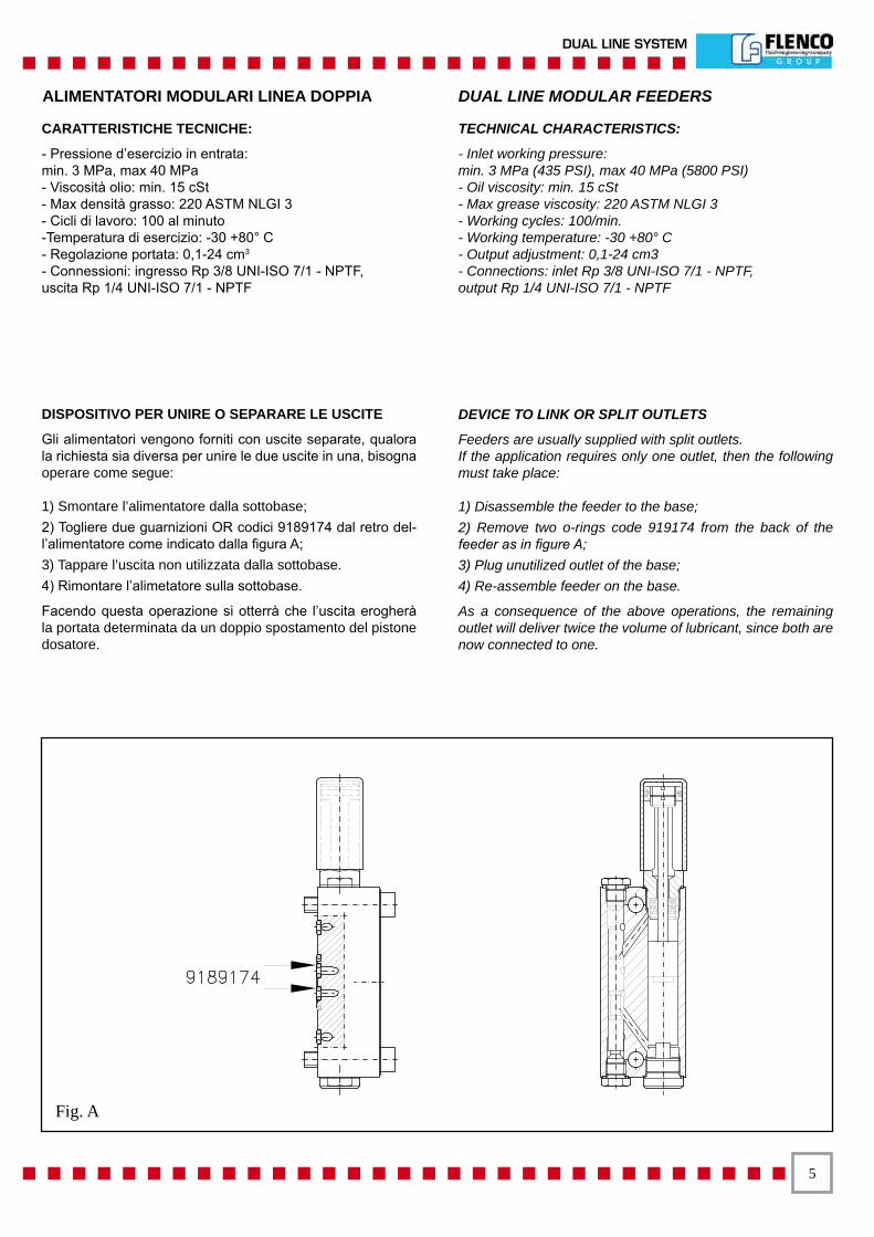
Gli alimentatori vengono forniti con uscite separate, qualora la richiesta sia diversa per unire le due uscite in una, bisogna operare come segue:
1) Smontare l’alimentatore dalla sottobase;2) Togliere due guarnizioni OR codici 9189174 dal retro del-l’alimentatore come indicato dalla figura A;3) Tappare l’uscita non utilizzata dalla sottobase.4) Rimontare l’alimetatore sulla sottobase.
Facendo questa operazione si otterrà che l’uscita erogherà la portata determinata da un doppio spostamento del pistone dosatore.
DEVICE TO LINK OR SPLIT OUTLETS
Feeders are usually supplied with split outlets. If the application requires only one outlet, then the following must take place:
1) Disassemble the feeder to the base; 2) Remove two o-rings code 919174 from the back of the feeder as in figure A; 3) Plug unutilized outlet of the base; 4) Re-assemble feeder on the base.
As a consequence of the above operations, the remaining outlet will deliver twice the volume of lubricant, since both are now connected to one.
Fig. A
�
SISTEMA DOPPIA LINEA
ALIMENTATORI MODULARI LINEA DOPPIA DUAL LINE MODULAR FEEDERS
Acciaio AVPCarbon Steel
Acciaio InoxStainless Steel
DescrizioneDescription
Filettatura Thread BSP
FilettaturaThread NPTF
FilettaturaThread BSP
FilettaturaThread NPTF
PortataOutput
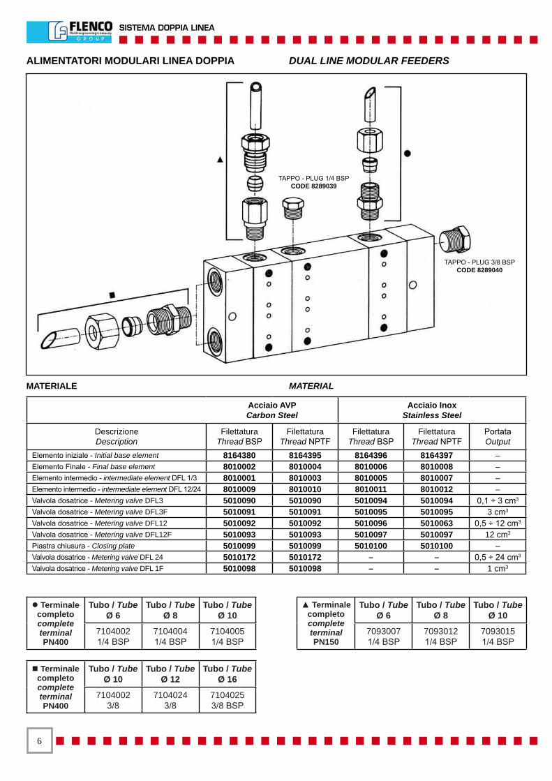
Elemento iniziale - Initial base element 8164380 8164395 8164396 8164397 – Elemento Finale - Final base element 8010002 8010004 8010006 8010008 – Elemento intermedio - intermediate element DFL 1/3 8010001 8010003 8010005 8010007 – Elemento intermedio - intermediate element DFL 12/24 8010009 8010010 8010011 8010012 – Valvola dosatrice - Metering valve DFL3 5010090 5010090 5010094 5010094 0,1 ÷ 3 cm3 Valvola dosatrice - Metering valve DFL3F 5010091 5010091 5010095 5010095 3 cm3 Valvola dosatrice - Metering valve DFL12 5010092 5010092 5010096 5010063 0,5 ÷ 12 cm3 Valvola dosatrice - Metering valve DFL12F 5010093 5010093 5010097 5010097 12 cm3
Piastra chiusura - Closing plate 5010099 5010099 5010100 5010100 – Valvola dosatrice - Metering valve DFL 24 5010172 5010172 – – 0,5 ÷ 24 cm3 Valvola dosatrice - Metering valve DFL 1F 5010098 5010098 – – 1 cm3
l Terminale completocomplete terminalPN400
Tubo / Tube Ø 6
Tubo / Tube Ø 8
Tubo / Tube Ø 10
71040021/4 BSP
71040041/4 BSP
71040051/4 BSP
▲ Terminale completocomplete terminalPN150
Tubo / Tube Ø 6
Tubo / Tube Ø 8
Tubo / Tube Ø 10
70930071/4 BSP
70930121/4 BSP
70930151/4 BSP
n Terminale completocomplete terminalPN400
Tubo / Tube Ø 10
Tubo / Tube Ø 12
Tubo / Tube Ø 16
71040023/8
71040243/8
71040253/8 BSP
TAPPO - PLUG 1/4 BSPCODE 8289039
TAPPO - PLUG 3/8 BSPCODE 8289040
MATERIALE MATERIAL
�
DUAL LINE SYSTEM
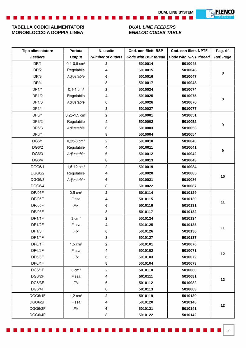
Tipo alimentatore Portata N. uscite Cod. con filett. BSP Cod. con filett. NPTF Pag. rif. Feeders Output Number of outlets Code with BSP thread Code with NPTF thread Ref. Page
DP/1 0,1-0,5 cm3 2 5010014 5010045
8 DP/2 Regolabile 4 5010015 5010046DP/3 Adjustable 6 5010016 5010047DP/4 8 5010017 5010048
DP1/1 0,1-1 cm3 2 5010024 5010074
8 DP1/2 Regolabile 4 5010025 5010075DP1/3 Adjustable 6 5010026 5010076DP1/4 8 5010027 5010077
DP6/1 0,25-1,5 cm3 2 5010001 5010051
9 DP6/2 Regolabile 4 5010002 5010052DP6/3 Adjustable 6 5010003 5010053DP6/4 8 5010004 5010054
DG6/1 0,25-3 cm3 2 5010010 5010040
9 DG6/2 Regolabile 4 5010011 5010041 DG6/3 Adjustable 6 5010012 5010042DG6/4 8 5010013 5010043
DGG6/1 1,5-12 cm3 2 5010019 5010084
10 DGG6/2 Regolabile 4 5010020 5010085DGG6/3 Adjustable 6 5010021 5010086DGG6/4 8 5010022 5010087
DP/05F 0,5 cm3 2 5010114 5010129
11 DP/05F Fissa 4 5010115 5010130DP/05F Fix 6 5010116 5010131DP/05F 8 5010117 5010132
DP1/1F 1 cm3 2 5010124 5010134
11 DP1/2F Fissa 4 5010125 5010135DP1/3F Fix 6 5010126 5010136DP1/4F 8 5010127 5010137
DP6/1F 1,5 cm3 2 5010101 5010070
12DP6/2F Fissa 4 5010102 5010071 DP6/3F Fix 6 5010103 5010072DP6/4F 8 5010104 5010073
DG6/1F 3 cm3 2 5010110 5010080
12 DG6/2F Fissa 4 5010111 5010081DG6/3F Fix 6 5010112 5010082DG6/4F 8 5010113 5010083
DGG6/1F 1,2 cm3 2 5010119 5010139
12 DGG6/2F Fissa 4 5010120 5010140 DGG6/3F Fix 6 5010121 5010141 DGG6/4F 8 5010122 5010142
TABELLA CODICI ALIMENTATORI DUAL LINE FEEDERSMONOBLOCCO A DOPPIA LINEA ENBLOC CODES TABLE
�
SISTEMA DOPPIA LINEA
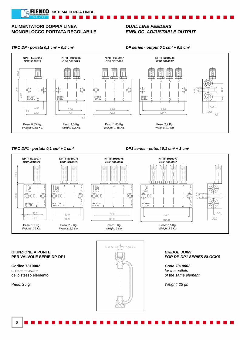
ALIMENTATORI DOPPIA LINEA DUAL LINE FEEDERSMONOBLOCCO PORTATA REGOLABILE ENBLOC ADJUSTABLE OUTPUT
GIUNZIONE A PONTEPER VALVOLE SERIE DP-DP1
Codice 7310002unisce le uscitedello stesso elemento
Peso: 25 gr
BRIDGE JOINTFOR DP-DP1 SERIES BLOCKS
Code 7310002for the outletsof the same element
Weight: 25 gr.
TIPO DP - portata 0,1 cm3 ÷ 0,5 cm3 DP series - output 0,1 cm3 ÷ 0,5 cm3
TIPO DP1 - portata 0,1 cm3 ÷ 1 cm3 DP1 series - output 0,1 cm3 ÷ 1 cm3
NPTF 5010045BSP 5010014
NPTF 5010047BSP 5010016
NPTF 5010046BSP 5010015
NPTF 5010048BSP 5010017
Peso: 0,85 Kg.Weight: 0,85 Kg.
Peso: 1,65 Kg.Weight: 1,65 Kg.
Peso: 1,3 Kg.Weight: 1,3 Kg.
Peso: 2,2 Kg.Weight: 2,2 Kg.
NPTF 5010074BSP 5010024
NPTF 5010076BSP 5010026
NPTF 5010075BSP 5010025
NPTF 5010077BSP 5010027
Peso: 1,6 Kg.Weight: 1,6 Kg.
Peso: 3 Kg.Weight: 3 Kg.
Peso: 2,2 Kg.Weight: 2,2 Kg.
Peso: 3,5 Kg.Weight:3,5 Kg.
�
DUAL LINE SYSTEM
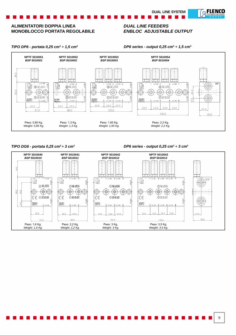
ALIMENTATORI DOPPIA LINEA DUAL LINE FEEDERSMONOBLOCCO PORTATA REGOLABILE ENBLOC ADJUSTABLE OUTPUT
TIPO DP6 - portata 0,25 cm3 ÷ 1,5 cm3 DP6 series - output 0,25 cm3 ÷ 1,5 cm3
TIPO DG6 - portata 0,25 cm3 ÷ 3 cm3 DP6 series - output 0,25 cm3 ÷ 3 cm3
NPTF 5010051BSP 5010001
NPTF 5010053BSP 5010003
NPTF 5010052BSP 5010002
NPTF 5010054BSP 5010004
Peso: 0,85 Kg.Weight: 0,85 Kg.
Peso: 1,65 Kg.Weight: 1,65 Kg.
Peso: 1,3 Kg.Weight: 1,3 Kg.
Peso: 2,2 Kg.Weight: 2,2 Kg.
NPTF 5010040BSP 5010010
NPTF 5010042BSP 5010012
NPTF 5010041BSP 5010011
NPTF 5010043BSP 5010013
Peso: 1,6 Kg.Weight: 1,6 Kg.
Peso: 3 Kg.Weight: 3 Kg.
Peso: 2,2 Kg.Weight: 2,2 Kg.
Peso: 3,5 Kg.Weight: 3,5 Kg.

�0
SISTEMA DOPPIA LINEA
Tappo biancoWhite plug 0,18 ÷ 3 cm3 8186003
Tappo nero Black plug 1,25 ÷ 4 cm3 8186031
Tipo DP Tipo DPI Tipo DP6 Tipo DG6/DD Tipo DGG6
CappuccioCap 8141016 8141018 8141010 8141001 8141020
ALIMENTATORI DOPPIA LINEA DUAL LINE FEEDERSMONOBLOCCO PORTATA REGOLABILE ENBLOC ADJUSTABLE OUTPUT
TIPO DGG6 - portata 1,5 cm3 ÷ 12 cm3 DGG6 series - output 1,5 cm3 ÷ 12 cm3
SPECIALE PER MERCATO USA (DD52-54-56-58)TIPO DD5 - portata 0,18 cm3 ÷ 4 cm3
SPECIALFORUSAMARKETDD5 series - output 0,18 cm3 ÷ 4 cm3
NPTF 5010084BSP 5010019
NPTF 5010086BSP 5010021
NPTF 5010085BSP 5010020
NPTF 5010087BSP 5010022
Peso: 4,6 Kg.Weight: 4,6 Kg.
Peso: 9,2 Kg.Weight: 9,2 Kg.
Peso: 6,650 Kg.Weight: 6,650 Kg.
Peso: 11,4 Kg.Weight: 11,4 Kg.
NPTF 5010143 NPTF 5010145NPTF 5010144 NPTF 5010146
Peso: 1,6 Kg.Weight: 1,6 Kg.
Peso: 3 Kg.Weight: 3 Kg.
Peso: 2,2 Kg.Weight: 2,2 Kg.
Peso: 3,5 Kg.Weight: 3,5 Kg.
��
DUAL LINE SYSTEM
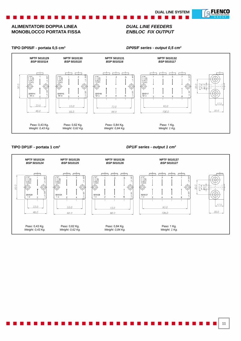
ALIMENTATORI DOPPIA LINEA DUAL LINE FEEDERSMONOBLOCCO PORTATA FISSA ENBLOC FIX OUTPUT
TIPO DP05/F - portata 0,5 cm3 DP05/F series - output 0,5 cm3
TIPO DP1/F - portata 1 cm3 DP1/F series - output 1 cm3
NPTF 5010134BSP 5010124
NPTF 5010136BSP 5010126
NPTF 5010135BSP 5010125
NPTF 5010137BSP 5010127
Peso: 0,43 Kg.Weight: 0,43 Kg.
Peso: 0,84 Kg.Weight: 0,84 Kg.
Peso: 0,62 Kg.Weight: 0,62 Kg.
Peso: 1 Kg.Weight: 1 Kg.
NPTF 5010129BSP 5010114
NPTF 5010131BSP 5010116
NPTF 5010130BSP 5010115
NPTF 5010132BSP 5010117
Peso: 0,43 Kg.Weight: 0,43 Kg.
Peso: 0,84 Kg.Weight: 0,84 Kg.
Peso: 0,62 Kg.Weight: 0,62 Kg.
Peso: 1 Kg.Weight: 1 Kg.

��
SISTEMA DOPPIA LINEA
ALIMENTATORI DOPPIA LINEA DUAL LINE FEEDERMONOBLOCCO PORTATA FISSA ENBLOC FIX OUTPUT
TIPO DP6/F - portata 1,5 cm3 DP6/F series - output 1,5 cm3
TIPO DG6/F - portata 3 cm3 DP6/F series - output 3 cm3
TIPO DGG6/F - portata 12 cm3 DGG6/F series - output 12 cm3
NPTF 5010070BSP 5010101
NPTF 5010072BSP 5010103
NPTF 5010071BSP 5010102
NPTF 5010073BSP 5010104
Peso: 0,82 Kg.Weight: 0,82 Kg.
Peso: 1,56 Kg.Weight: 1,56 Kg.
Peso: 1,23 Kg.Weight: 1,23 Kg.
Peso: 1,92 Kg.Weight: 1,92 Kg.
NPTF 5010080BSP 5010110
NPTF 5010082BSP 5010112
NPTF 5010181BSP 5010111
NPTF 5010083BSP 5010113
Peso: 1,56 Kg.Weight: 1,56 Kg.
Peso: 2,82 Kg.Weight: 2,82 Kg.
Peso: 2,16 Kg.Weight: 2,16 Kg.
Peso: 3,37 Kg.Weight: 3,37 Kg.
NPTF 5010139BSP 5010119
NPTF 5010141BSP 5010121
NPTF 5010140BSP 5010120
NPTF 5010142BSP 5010122
Peso: 4,5 Kg.Weight: 4,5 Kg.
Peso: 8,9 Kg.Weight: 8,9 Kg.
Peso: 6,45 Kg.Weight: 6,45 Kg.
Peso: 11 Kg.Weight: 11 Kg.
��
DUAL LINE SYSTEM
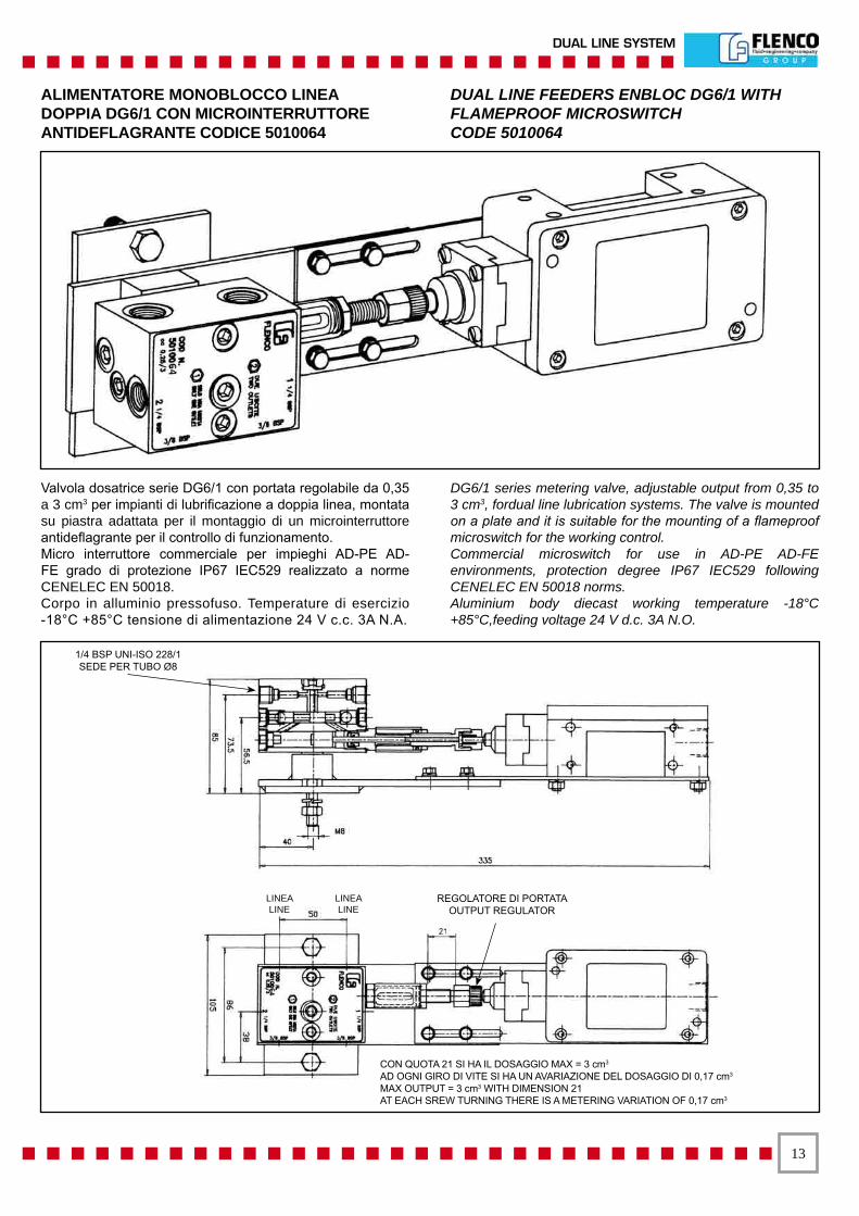
Valvola dosatrice serie DG6/1 con portata regolabile da 0,35 a 3 cm3 per impianti di lubrificazione a doppia linea, montata su piastra adattata per il montaggio di un microinterruttore antideflagrante per il controllo di funzionamento.Micro interruttore commerciale per impieghi AD-PE AD-FE grado di protezione IP67 IEC529 realizzato a norme CENELEC EN 50018.Corpo in alluminio pressofuso. Temperature di esercizio -18°C +85°C tensione di alimentazione 24 V c.c. 3A N.A.
DG6/1 series metering valve, adjustable output from 0,35 to 3 cm3, fordual line lubrication systems. The valve is mounted on a plate and it is suitable for the mounting of a flameproof microswitch for the working control.Commercial microswitch for use in AD-PE AD-FE environments, protection degree IP67 IEC529 following CENELEC EN 50018 norms.Aluminium body diecast working temperature -18°C +85°C,feeding voltage 24 V d.c. 3A N.O.
ALIMENTATORE MONOBLOCCO LINEA DOPPIA DG6/1 CON MICROINTERRUTTORE ANTIDEFLAGRANTE CODICE 5010064
DUAL LINE FEEDERS ENBLOC DG6/1 WITH FLAMEPROOF MICROSWITCHCODE 5010064
1/4 BSP UNI-ISO 228/1SEDE PER TUBO Ø8
REGOLATORE DI PORTATA OUTPUT REGULATOR
LINEA LINE
LINEA LINE
CON QUOTA 21 SI HA IL DOSAGGIO MAX = 3 cm3
AD OGNI GIRO DI VITE SI HA UN AVARIAZIONE DEL DOSAGGIO DI 0,17 cm3 MAX OUTPUT = 3 cm3 WITH DIMENSION 21AT EACH SREW TURNING THERE IS A METERING VARIATION OF 0,17 cm3
��
SISTEMA DOPPIA LINEA
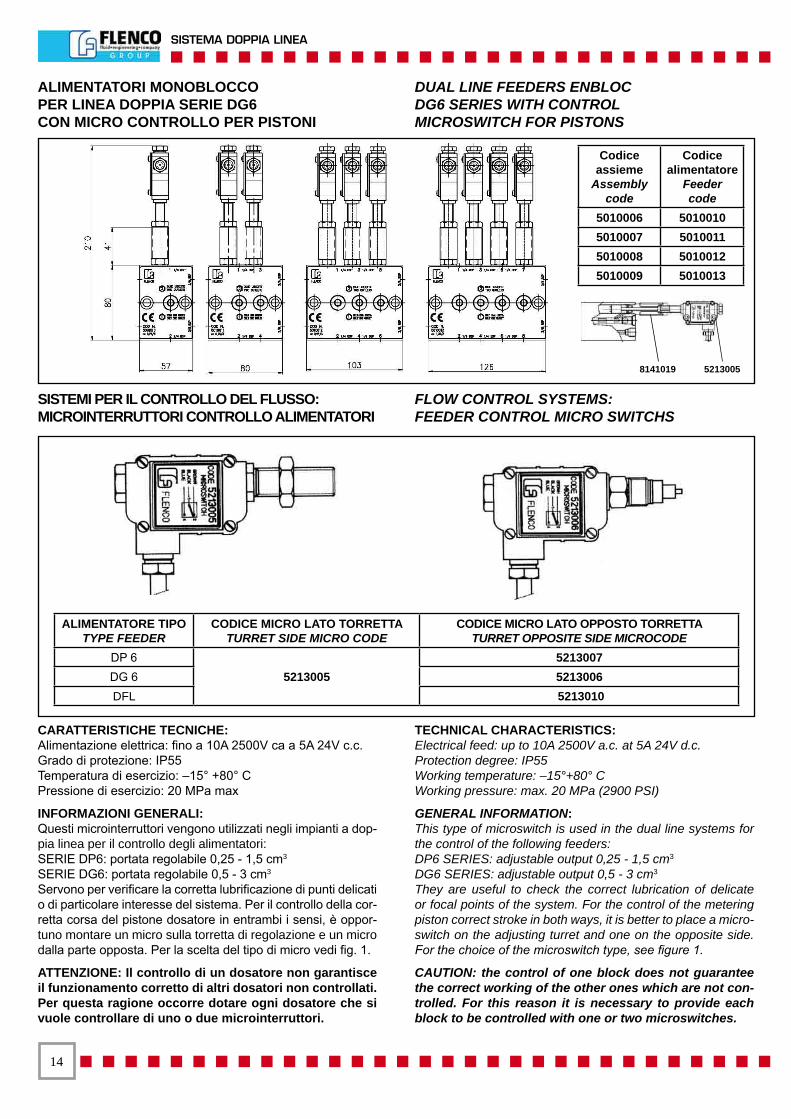
CARATTERISTICHE TECNICHE:Alimentazione elettrica: fino a 10A 2500V ca a 5A 24V c.c.Grado di protezione: IP55Temperatura di esercizio: –15° +80° CPressione di esercizio: 20 MPa max
INFORMAZIONI GENERALI:Questi microinterruttori vengono utilizzati negli impianti a dop-pia linea per il controllo degli alimentatori:SERIE DP6: portata regolabile 0,25 - 1,5 cm3
SERIE DG6: portata regolabile 0,5 - 3 cm3
Servono per verificare la corretta lubrificazione di punti delicati o di particolare interesse del sistema. Per il controllo della cor-retta corsa del pistone dosatore in entrambi i sensi, è oppor-tuno montare un micro sulla torretta di regolazione e un micro dalla parte opposta. Per la scelta del tipo di micro vedi fig. 1.
ATTENZIONE: Il controllo di un dosatore non garantisce il funzionamento corretto di altri dosatori non controllati. Per questa ragione occorre dotare ogni dosatore che si vuole controllare di uno o due microinterruttori.
TECHNICAL CHARACTERISTICS:Electrical feed: up to 10A 2500V a.c. at 5A 24V d.c.Protection degree: IP55Working temperature: –15°+80° CWorking pressure: max. 20 MPa (2900 PSI)
GENERAL INFORMATION:This type of microswitch is used in the dual line systems for the control of the following feeders:DP6 SERIES: adjustable output 0,25 - 1,5 cm3
DG6 SERIES: adjustable output 0,5 - 3 cm3
They are useful to check the correct lubrication of delicate or focal points of the system. For the control of the metering piston correct stroke in both ways, it is better to place a micro-switch on the adjusting turret and one on the opposite side. For the choice of the microswitch type, see figure 1.
CAUTION: the control of one block does not guarantee the correct working of the other ones which are not con-trolled. For this reason it is necessary to provide each block to be controlled with one or two microswitches.
Codiceassieme
Assembly code
Codicealimentatore
Feedercode
5010006 50100105010007 50100115010008 50100125010009 5010013
ALIMENTATORI MONOBLOCCOPER LINEA DOPPIA SERIE DG6CON MICRO CONTROLLO PER PISTONI
DUAL LINE FEEDERS ENBLOCDG6 SERIES WITH CONTROLMICROSWITCH FOR PISTONS
SISTEMI PER IL CONTROLLO DEL FLUSSO:MICROINTERRUTTORI CONTROLLO ALIMENTATORI
FLOW CONTROL SYSTEMS:FEEDER CONTROL MICRO SWITCHS
ALIMENTATORE TIPOTYPE FEEDER
CODICE MICRO LATO TORRETTATURRET SIDE MICRO CODE
CODICE MICRO LATO OPPOSTO TORRETTATURRET OPPOSITE SIDE MICROCODE
DP 6 5213005
5213007 DG 6 5213006 DFL 5213010
8141019 5213005
��
DUAL LINE SYSTEM
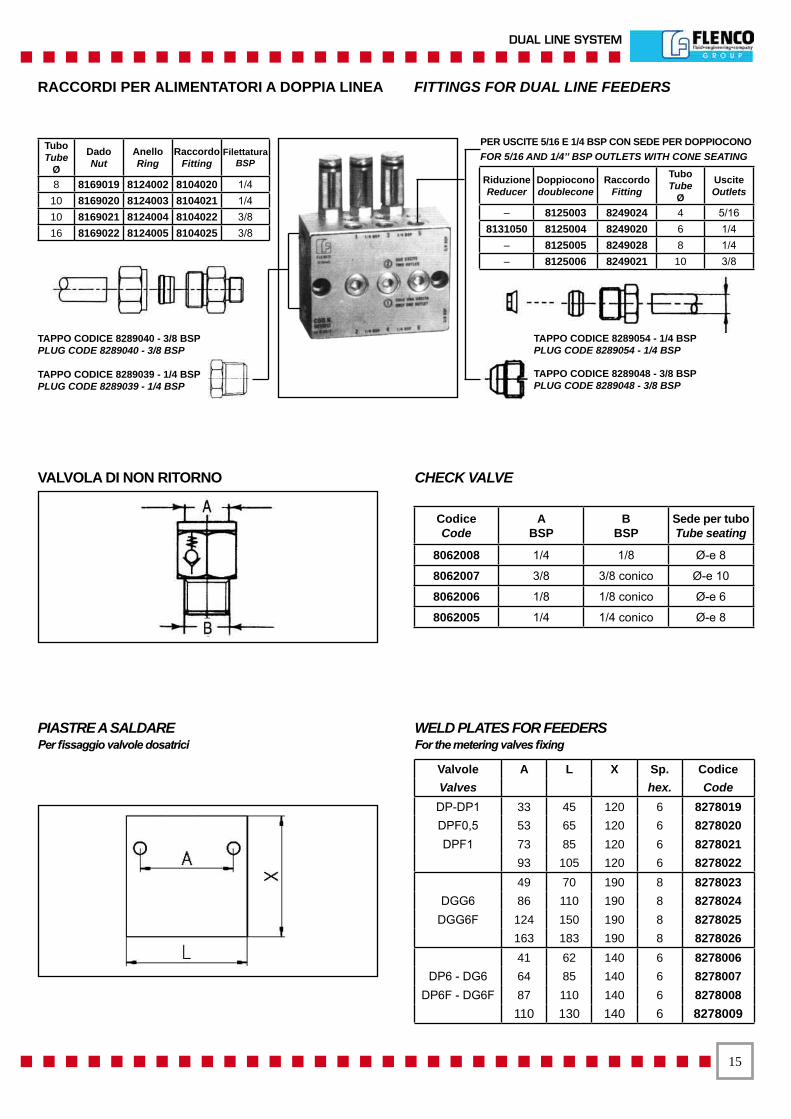
Valvole A L X Sp. Codice Valves hex. Code DP-DP1 33 45 120 6 8278019DPF0,5 53 65 120 6 8278020DPF1 73 85 120 6 8278021
93 105 120 6 827802249 70 190 8 8278023
DGG6 86 110 190 8 8278024 DGG6F 124 150 190 8 8278025
163 183 190 8 8278026 41 62 140 6 8278006
DP6 - DG6 64 85 140 6 8278007 DP6F - DG6F 87 110 140 6 8278008
110 130 140 6 8278009
RACCORDI PER ALIMENTATORI A DOPPIA LINEA FITTINGS FOR DUAL LINE FEEDERS
TAPPO CODICE 8289040 - 3/8 BSP PLUG CODE 8289040 - 3/8 BSP TAPPO CODICE 8289039 - 1/4 BSP PLUG CODE 8289039 - 1/4 BSP
PER USCITE 5/16 E 1/4 BSP CON SEDE PER DOPPIOCONO FOR 5/16 AND 1/4’’ BSP OUTLETS WITH CONE SEATING
Riduzione Reducer
Doppioconodoublecone
Raccordo Fitting
TuboTube
Ø
Uscite Outlets
– 8125003 8249024 4 5/16 8131050 8125004 8249020 6 1/4
– 8125005 8249028 8 1/4 – 8125006 8249021 10 3/8
TAPPO CODICE 8289054 - 1/4 BSP PLUG CODE 8289054 - 1/4 BSP
TAPPO CODICE 8289048 - 3/8 BSP PLUG CODE 8289048 - 3/8 BSP
TuboTube
Ø
DadoNut
AnelloRing
Raccordo Fitting
Filettatura BSP
8 8169019 8124002 8104020 1/4 10 8169020 8124003 8104021 1/4 10 8169021 8124004 8104022 3/8 16 8169022 8124005 8104025 3/8
CodiceCode
ABSP
BBSP
Sede per tubo Tube seating
8062008 1/4 1/8 Ø-e 8
8062007 3/8 3/8 conico Ø-e 10
8062006 1/8 1/8 conico Ø-e 6
8062005 1/4 1/4 conico Ø-e 8
VALVOLA DI NON RITORNO CHECK VALVE
PIASTRE A SALDAREPer fissaggio valvole dosatrici
WELD PLATES FOR FEEDERSFor the metering valves fixing
��
SISTEMA DOPPIA LINEA
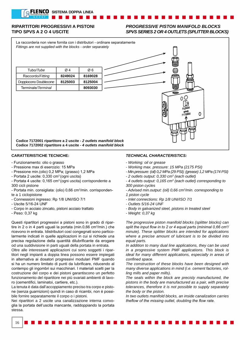
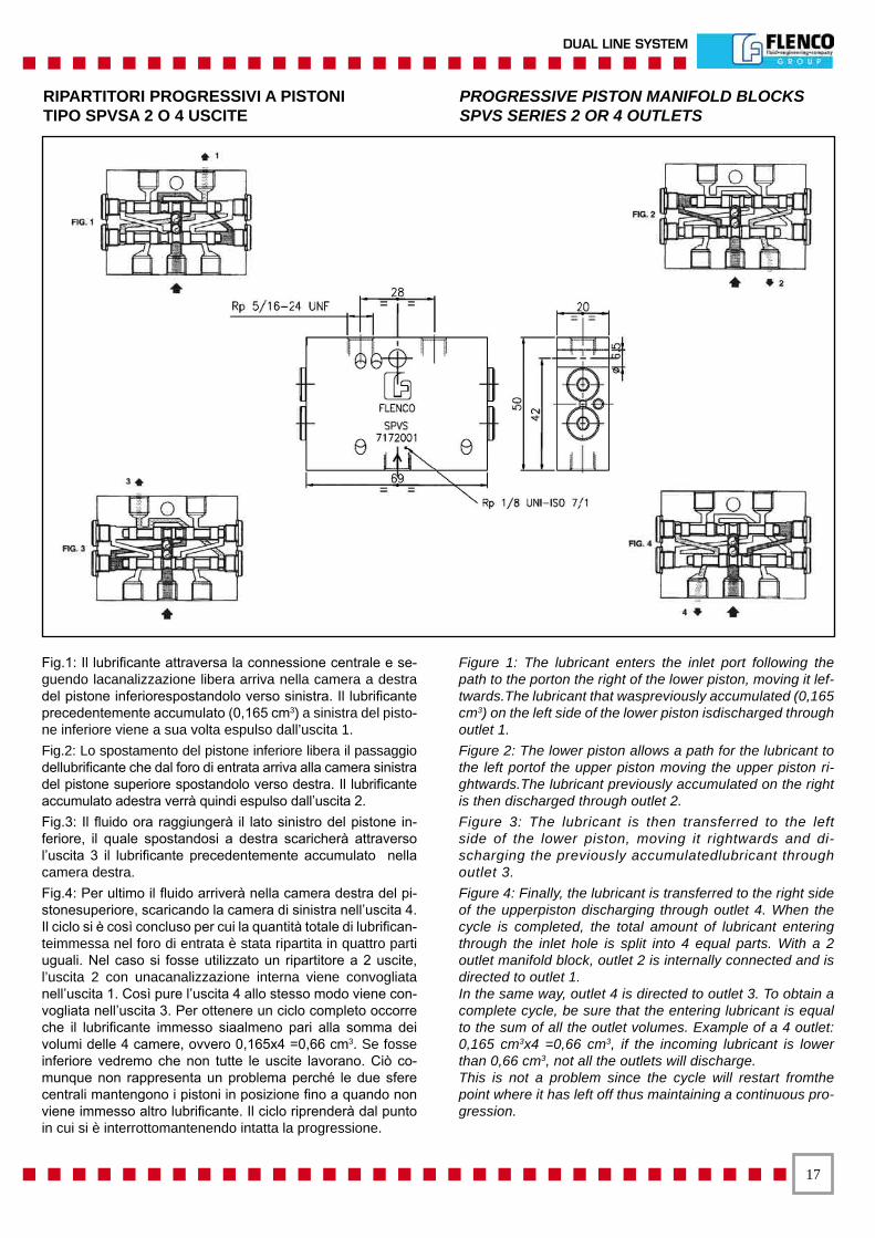
RIPARTITORI PROGRESSIVI A PISTONI PROGRESSIVE PISTON MANIFOLD BLOCKSTIPO SPVS A 2 O 4 USCITE SPVS SERIES 2 OR 4 OUTLETS (SPLITTER BLOCKS)
CARATTERISTICHE TECNICHE:
- Funzionamento: olio o grasso- Pressione max di esercizio: 15 MPa- Pressione min.(olio) 0,2 MPa; (grasso) 1,2 MPa- Portata 2 uscite: 0,330 cm3 (ogni uscita)- Portata 4 uscite: 0,165 cm3 (ogni uscita) corrispondente a 300 cicli pistone- Portata min. consigliata: (olio) 0,66 cm3/min. corrisponden-te a 1 ciclopistone- Connessioni ingresso: Rp 1/8 UNI/ISO 7/1- Uscite 5/16-24 UNF- Corpo in acciaio zincato, pistoni acciaio trattato- Peso: 0,37 kg
Questi ripartitori progressivi a pistoni sono in grado di ripar-tire in 2 o in 4 parti uguali la portata (min.0,66 cm3/min.) che ricevono in entrata. Idistributori così congegnati sono partico-larmente indicati in quelle applicazioni in cui si richiede una precisa regolazione della quantità dilubrificante da erogare od una suddivisione in parti uguali della portata in entrata.Oltre alle interessanti applicazioni cui sono soggetti i ripar-titori negli impianti a doppia linea possono essere impiegati in alternativa ai dosatori progressivi modulari PMF quando si ha un numero limitato di punti da lubrificare, riducendo al contempo gli ingombri sui macchinari. I materiali scelti per la costruzione del corpo e dei pistoni garantiscono un perfetto funzionamento del ripartitore nei più svariati ambienti di lavo-ro (cementifici, laminatoi, cartiere, etc.).La tenuta è data dall’accoppiamento preciso tra corpo e pisto-ne (senza guarnizioni) quindi in caso di ricambi, non è possi-bile fornire separatamente il corpo o i pistoni.Nei ripartitori a 2 uscite una canalizzazione interna convo-glia la portata dell’uscita mancante, raddoppiando la portata stessa.
TECHNICAL CHARACTERISTICS:
- Working: oil or grease- Working max. pressure: 15 MPa (2175 PSI)- Min.pressure: (oil) 0,2 MPa (29 PSI); (grease) 1,2 MPa (174 PSI)- 2 outlets output: 0,330 cm3 (each outlet)- 4 outlets output: 0,165 cm3 (each outlet) corresponding to 300 piston cycles- Advised min.output: (oil) 0,66 cm3/min. corresponding to1 piston cycle- Inlet connections: Rp 1/8 UNI/ISO 7/1- Outlets 5/16-24 UNF- Body in galvanized steel, pistons in treated steel- Weight: 0,37 kg
The progressive piston manifold blocks (splitter blocks) can split the input flow in to 2 or 4 equal parts (minimal 0,66 cm3/minute). These splitter blocks are intended for applications where a precise amount of lubricant is to be divided into equal parts.In addition to many dual line applications, they can be used in a progressive system PMF applications. This block is ideal for many different applications, especially in areas of confined space.The construction of these blocks have been designed with many diverse applications in mind (i.e. cement factories, rol-ling mills and paper mills).The seals within the block are precisly manufactured, the pistons in the body are manufactured as a pair, with precise tolerances, therefore it is not possible to supply separately the body or the piston.In two outlets manifold blocks, an inside canalization carries theflow of the missing outlet, doubling the flow rate.
Tubo/Tube Ø 4 Ø 6Raccordo/Fitting 8249024 8169028
Doppiocono Doublecone 8125003 8125004Terminale/Terminal 8093030
Codice 7172001 ripartitore a 2 uscite - 2 outlets manifold blockCodice 7172002 ripartitore a 4 uscite - 4 outlets manifold block
La raccorderia non viene fornita con i distributori - ordinare separatamenteFittings are not supplied with the blocks - order separately
��
DUAL LINE SYSTEM
RIPARTITORI PROGRESSIVI A PISTONI PROGRESSIVE PISTON MANIFOLD BLOCKSTIPO SPVSA 2 O 4 USCITE SPVS SERIES 2 OR 4 OUTLETS
Fig.1: Il lubrificante attraversa la connessione centrale e se-guendo lacanalizzazione libera arriva nella camera a destra del pistone inferiorespostandolo verso sinistra. Il lubrificante precedentemente accumulato (0,165 cm3) a sinistra del pisto-ne inferiore viene a sua volta espulso dall’uscita 1.Fig.2: Lo spostamento del pistone inferiore libera il passaggio dellubrificante che dal foro di entrata arriva alla camera sinistra del pistone superiore spostandolo verso destra. Il lubrificante accumulato adestra verrà quindi espulso dall’uscita 2.Fig.3: Il fluido ora raggiungerà il lato sinistro del pistone in-feriore, il quale spostandosi a destra scaricherà attraverso l’uscita 3 il lubrificante precedentemente accumulato nella camera destra.Fig.4: Per ultimo il fluido arriverà nella camera destra del pi-stonesuperiore, scaricando la camera di sinistra nell’uscita 4. Il ciclo si è così concluso per cui la quantità totale di lubrifican-teimmessa nel foro di entrata è stata ripartita in quattro parti uguali. Nel caso si fosse utilizzato un ripartitore a 2 uscite, l’uscita 2 con unacanalizzazione interna viene convogliata nell’uscita 1. Così pure l’uscita 4 allo stesso modo viene con-vogliata nell’uscita 3. Per ottenere un ciclo completo occorre che il lubrificante immesso siaalmeno pari alla somma dei volumi delle 4 camere, ovvero 0,165x4 =0,66 cm3. Se fosse inferiore vedremo che non tutte le uscite lavorano. Ciò co-munque non rappresenta un problema perché le due sfere centrali mantengono i pistoni in posizione fino a quando non viene immesso altro lubrificante. Il ciclo riprenderà dal punto in cui si è interrottomantenendo intatta la progressione.
Figure 1: The lubricant enters the inlet port following the path to the porton the right of the lower piston, moving it lef-twards.The lubricant that waspreviously accumulated (0,165 cm3) on the left side of the lower piston isdischarged through outlet 1.Figure 2: The lower piston allows a path for the lubricant to the left portof the upper piston moving the upper piston ri-ghtwards.The lubricant previously accumulated on the right is then discharged through outlet 2.Figure 3: The lubricant is then transferred to the left side of the lower piston, moving it rightwards and di-scharging the previously accumulatedlubricant through outlet 3.Figure 4: Finally, the lubricant is transferred to the right side of the upperpiston discharging through outlet 4. When the cycle is completed, the total amount of lubricant entering through the inlet hole is split into 4 equal parts. With a 2 outlet manifold block, outlet 2 is internally connected and is directed to outlet 1.In the same way, outlet 4 is directed to outlet 3. To obtain a complete cycle, be sure that the entering lubricant is equal to the sum of all the outlet volumes. Example of a 4 outlet: 0,165 cm3x4 =0,66 cm3, if the incoming lubricant is lower than 0,66 cm3, not all the outlets will discharge.This is not a problem since the cycle will restart fromthe point where it has left off thus maintaining a continuous pro-gression.
��
SISTEMA DOPPIA LINEA
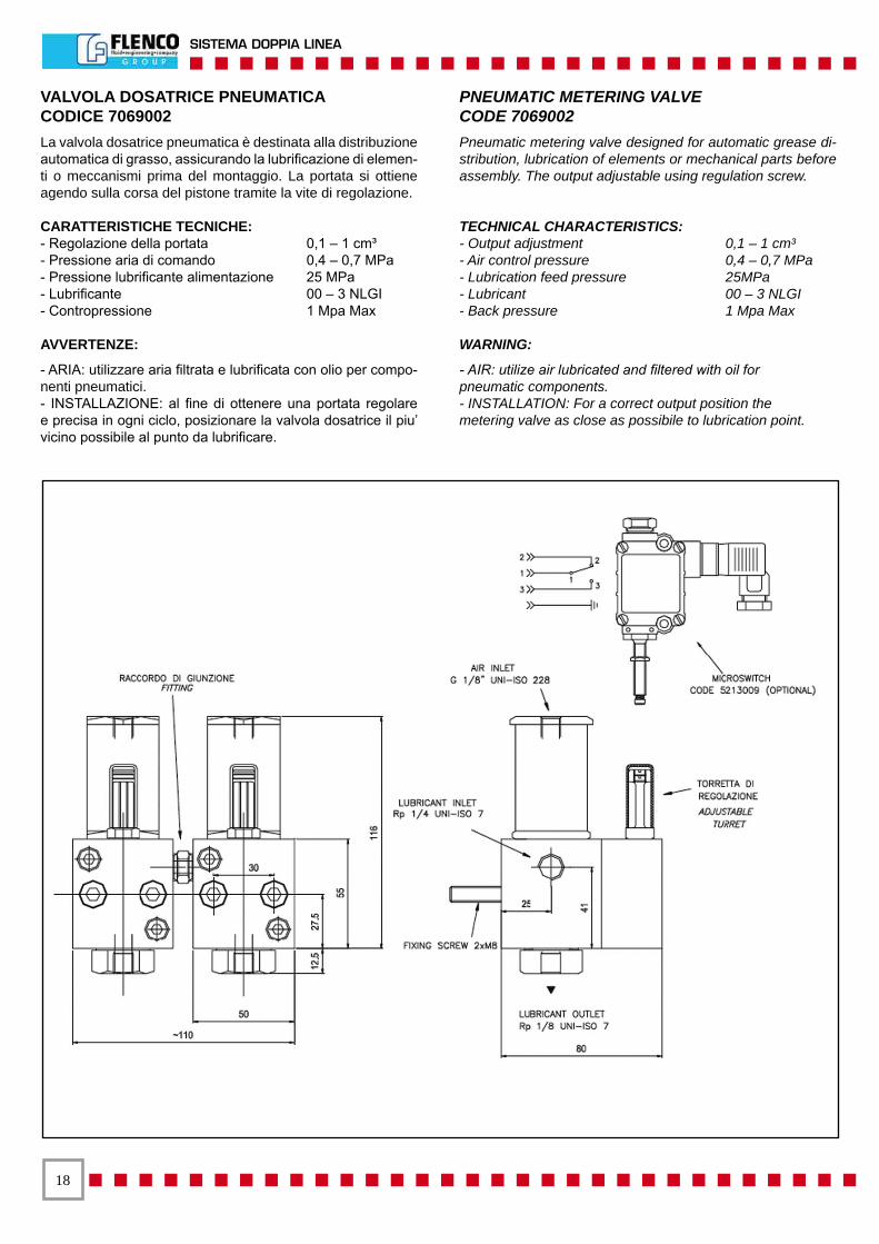
VALVOLA DOSATRICE PNEUMATICACODICE 7069002La valvola dosatrice pneumatica è destinata alla distribuzione automatica di grasso, assicurando la lubrificazione di elemen-ti o meccanismi prima del montaggio. La portata si ottiene agendo sulla corsa del pistone tramite la vite di regolazione.
CARATTERISTICHE TECNICHE:- Regolazione della portata 0,1 – 1 cm³- Pressione aria di comando 0,4 – 0,7 MPa- Pressione lubrificante alimentazione 25 MPa- Lubrificante 00 – 3 NLGI- Contropressione 1 Mpa Max
AVVERTENZE:
- ARIA: utilizzare aria filtrata e lubrificata con olio per compo-nenti pneumatici.- INSTALLAZIONE: al fine di ottenere una portata regolare e precisa in ogni ciclo, posizionare la valvola dosatrice il piu’ vicino possibile al punto da lubrificare.
PNEUMATIC METERING VALVECODE 7069002Pneumatic metering valve designed for automatic grease di-stribution, lubrication of elements or mechanical parts before assembly. The output adjustable using regulation screw.
TECHNICAL CHARACTERISTICS:- Output adjustment 0,1 – 1 cm³- Air control pressure 0,4 – 0,7 MPa- Lubrication feed pressure 25MPa- Lubricant 00 – 3 NLGI- Back pressure 1 Mpa Max
WARNING:
- AIR: utilize air lubricated and filtered with oil forpneumatic components.- INSTALLATION: For a correct output position themetering valve as close as possibile to lubrication point.
��
DUAL LINE SYSTEM
VALVOLA DOSATRICE PNEUMATICACODICE 7069002
PNEUMATIC METERING VALVECODE 7069002
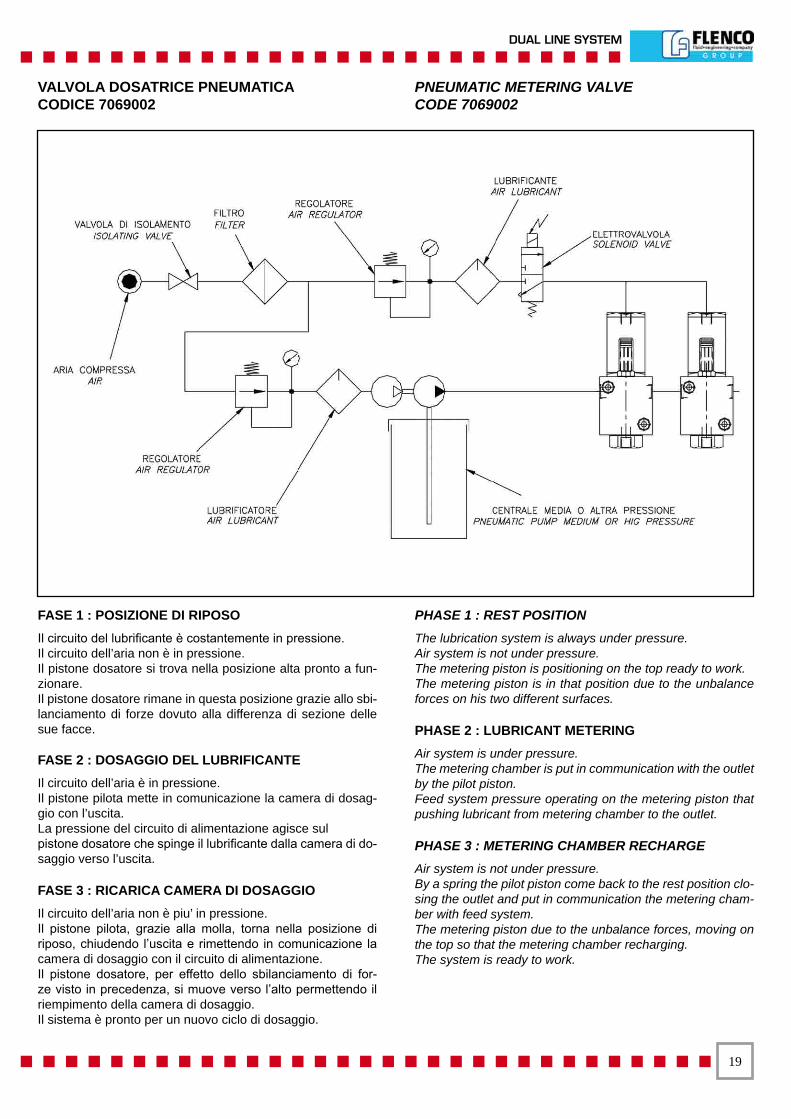
FASE 1 : POSIZIONE DI RIPOSOIl circuito del lubrificante è costantemente in pressione.Il circuito dell’aria non è in pressione.Il pistone dosatore si trova nella posizione alta pronto a fun-zionare.Il pistone dosatore rimane in questa posizione grazie allo sbi-lanciamento di forze dovuto alla differenza di sezione delle sue facce.
FASE 2 : DOSAGGIO DEL LUBRIFICANTEIl circuito dell’aria è in pressione.Il pistone pilota mette in comunicazione la camera di dosag-gio con l’uscita.La pressione del circuito di alimentazione agisce sulpistone dosatore che spinge il lubrificante dalla camera di do-saggio verso l’uscita.
FASE 3 : RICARICA CAMERA DI DOSAGGIOIl circuito dell’aria non è piu’ in pressione.Il pistone pilota, grazie alla molla, torna nella posizione di riposo, chiudendo l’uscita e rimettendo in comunicazione la camera di dosaggio con il circuito di alimentazione.Il pistone dosatore, per effetto dello sbilanciamento di for-ze visto in precedenza, si muove verso l’alto permettendo il riempimento della camera di dosaggio.Il sistema è pronto per un nuovo ciclo di dosaggio.
PHASE 1 : REST POSITIONThe lubrication system is always under pressure.Air system is not under pressure.The metering piston is positioning on the top ready to work.The metering piston is in that position due to the unbalance forces on his two different surfaces.
PHASE 2 : LUBRICANT METERINGAir system is under pressure.The metering chamber is put in communication with the outlet by the pilot piston.Feed system pressure operating on the metering piston that pushing lubricant from metering chamber to the outlet.
PHASE 3 : METERING CHAMBER RECHARGEAir system is not under pressure.By a spring the pilot piston come back to the rest position clo-sing the outlet and put in communication the metering cham-ber with feed system.The metering piston due to the unbalance forces, moving on the top so that the metering chamber recharging.The system is ready to work.
�0
SISTEMA DOPPIA LINEA
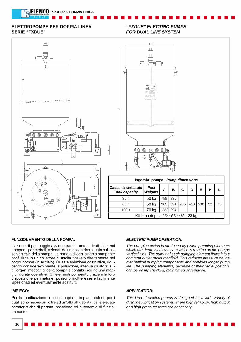
ELETTROPOMPE PER DOPPIA LINEA “FXDUE” ELECTRIC PUMPSSERIE “FXDUE” FOR DUAL LINE SYSTEM
Ingombri pompa / Pump dimensions
Capacità serbatoioTank capacity
PesiWeights A B C D E H L
30 lt 50 kg 788 330285 410 580 32 7560 lt 58 kg 983 394
100 lt 70 kg 1383 394 Kit linea doppia / Dual line kit : 23 kg
IMPIEGO:
Per la lubrificazione a linea doppia di impianti estesi, per i quali sono necessari, oltre ad un’alta affidabilità, delle elevate caratteristiche di portata, pressione ed autonomia di funzio-namento.
APPLICATION:
This kind of electric pumps is designed for a wide variety of dual line lubrication systems where high reliability, high output and high pressure rates are necessary.
FUNZIONAMENTO DELLA POMPA:L’azione di pompaggio avviene tramite una serie di elementi pompanti perimetrali, azionati da un eccentrico situato sull’as-se verticale della pompa. La portata di ogni singolo pompante confluisce in un collettore di uscita ricavato direttamente nel corpo pompa (in acciaio). Questa soluzione costruttiva, ridu-cendo considerevolmente le pulsazioni, attenua gli sforzi su-gli organi meccanici della pompa e contribuisce ad una mag-gior durata operativa. Gli elementi pompanti, grazie alla loro disposizione perimetrale, possono inoltre essere facilmente ispezionati ed eventualmente sostituiti.
ELECTRIC PUMP OPERATION:The pumping action is produced by piston pumping elements which are depressed by a cam which is rotating on the pumps vertical axis. The output of each pumping element flows into a common outlet radial manifold. This reduces pressure on the mechanical pumping components and provides longer pump life. The pumping elements, because of their radial position, can be easily checked, maintained or replaced.
��
DUAL LINE SYSTEM
ELETTROPOMPE PER GRASSO ELECTRIC PUMPS FOR GREASE
Codice pompacompleto di kit
Pump code with kit
Codice pompaPump code
PortataOutput
cm3 / min.
N. pompantiNumber of
pumping elem.
Codice pompante Pumping element
code
Capacità serbatoio
Tank capacity
Quote / Dimensions
A B5015230 5015220 120 +/-10% 6
7234030
30 kg 788 3305015231 5015221 120 +/-10% 6 60 kg 983 3945015232 5015222 120 +/-10% 6 100 kg 1383 3945015233 5015223 240 +/-10% 12 30 kg 788 3305015234 5015224 240 +/-10% 12 60 kg 983 3945015235 5015225 240 +/-10% 12 100 kg 1383 3945015236 5015237 120 +/-10% 6 10 kg 623 2605015260 5015261 100 +/-10% 5 10 kg 623 2605015263 5015264 100 +/-10% 5 30 kg 788 330
CARATTERISTICHE TECNICHE:
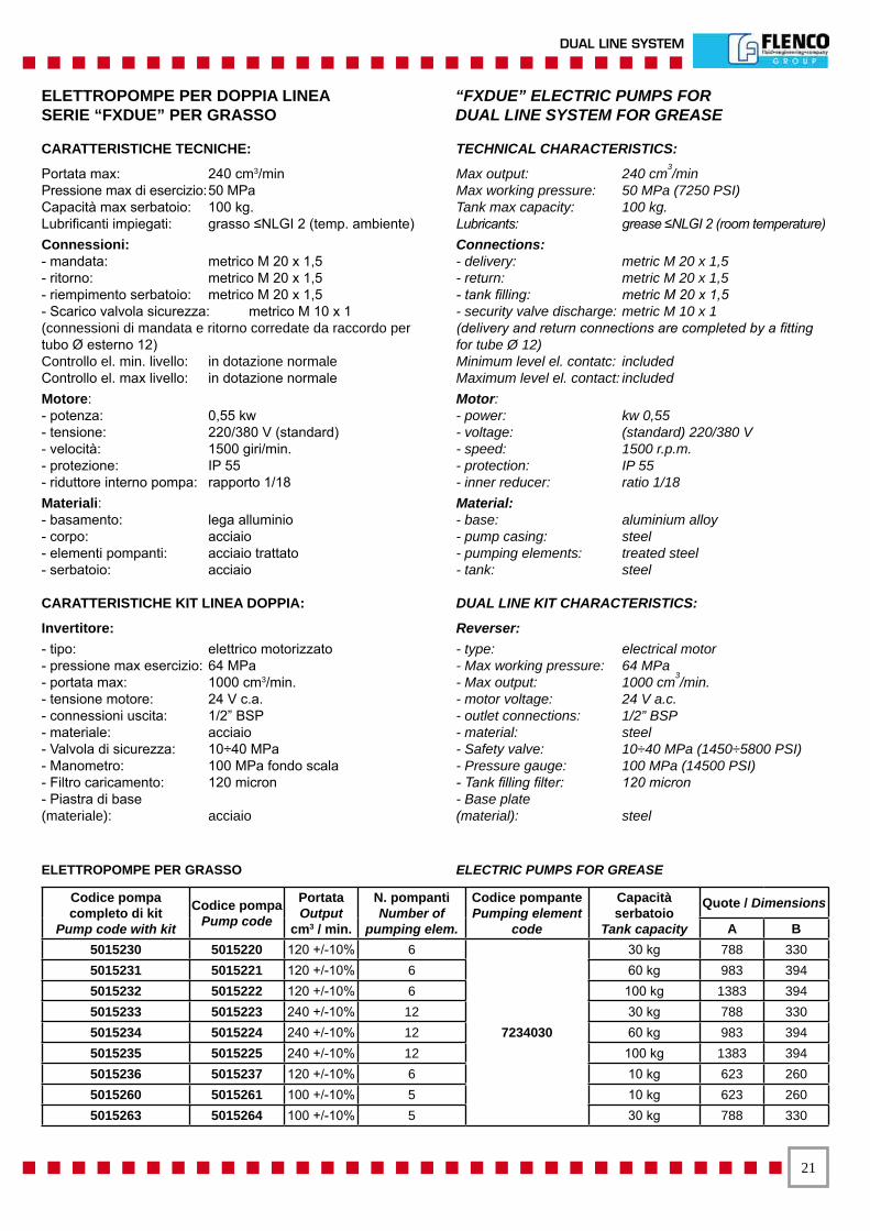
Portata max: 240 cm3/minPressione max di esercizio: 50 MPaCapacità max serbatoio: 100 kg.Lubrificanti impiegati: grasso ≤NLGI 2 (temp. ambiente)Connessioni:- mandata: metrico M 20 x 1,5 - ritorno: metrico M 20 x 1,5 - riempimento serbatoio: metrico M 20 x 1,5- Scarico valvola sicurezza: metrico M 10 x 1(connessioni di mandata e ritorno corredate da raccordo per tubo Ø esterno 12)Controllo el. min. livello: in dotazione normaleControllo el. max livello: in dotazione normale Motore:- potenza: 0,55 kw - tensione: 220/380 V (standard) - velocità: 1500 giri/min. - protezione: IP 55 - riduttore interno pompa: rapporto 1/18 Materiali:- basamento: lega alluminio - corpo: acciaio - elementi pompanti: acciaio trattato - serbatoio: acciaio
CARATTERISTICHE KIT LINEA DOPPIA:
Invertitore:- tipo: elettrico motorizzato - pressione max esercizio: 64 MPa - portata max: 1000 cm3/min. - tensione motore: 24 V c.a. - connessioni uscita: 1/2” BSP - materiale: acciaio- Valvola di sicurezza: 10÷40 MPa- Manometro: 100 MPa fondo scala- Filtro caricamento: 120 micron- Piastra di base(materiale): acciaio
TECHNICAL CHARACTERISTICS:
Max output: 240 cm3/minMax working pressure: 50 MPa (7250 PSI)Tank max capacity: 100 kg.Lubricants: grease ≤NLGI 2 (room temperature)Connections:- delivery: metric M 20 x 1,5 - return: metric M 20 x 1,5 - tank filling: metric M 20 x 1,5 - security valve discharge: metric M 10 x 1(delivery and return connections are completed by a fitting for tube Ø 12)Minimum level el. contatc: includedMaximum level el. contact: included Motor:- power: kw 0,55 - voltage: (standard) 220/380 V - speed: 1500 r.p.m. - protection: IP 55 - inner reducer: ratio 1/18 Material:- base: aluminium alloy - pump casing: steel - pumping elements: treated steel - tank: steel
DUAL LINE KIT CHARACTERISTICS:
Reverser:- type: electrical motor - Max working pressure: 64 MPa - Max output: 1000 cm3/min. - motor voltage: 24 V a.c.- outlet connections: 1/2” BSP - material: steel- Safety valve: 10÷40 MPa (1450÷5800 PSI)- Pressure gauge: 100 MPa (14500 PSI)- Tank filling filter: 120 micron- Base plate(material): steel
ELETTROPOMPE PER DOPPIA LINEA “FXDUE” ELECTRIC PUMPS FORSERIE “FXDUE” PER GRASSO DUAL LINE SYSTEM FOR GREASE
��
SISTEMA DOPPIA LINEA
Codice pompa completo di kit Pump
code with kit
Codice pompa Pump code
Portata Output
cm3 / min.
N. pompanti Number of
pumping elem.
Codice pompante Pumping element
code
Capacità serbatoio
Tank capacity
Codice serbatoio Tank code
QuoteDimensions
A B5016021 5016001 120 +/-10% 6
7234030
30 lt. 7272029 704 325 5016022 5016002 120 +/-10% 6 60 lt. 7272030 894 395 5016023 5016003 120 +/-10% 6 100 lt. 7272031 1294 3955016024 5016004 240 +/-10% 12 30 lt. 7272029 704 325 5016025 5016005 240 +/-10% 12 60 lt. 7272030 894 395 5016026 5016006 240 +/-10% 12 100 lt. 7272031 1294 395
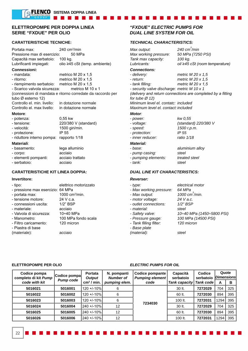
CARATTERISTICHE TECNICHE:
Portata max: 240 cm3/minPressione max di esercizio: 50 MPaCapacità max serbatoio: 100 kg.Lubrificanti impiegati: olio ≥45 cSt (temp. ambiente)Connessioni:- mandata: metrico M 20 x 1,5 - ritorno: metrico M 20 x 1,5 - riempimento serbatoio: metrico M 20 x 1,5- Scarico valvola sicurezza: metrico M 10 x 1(connessioni di mandata e ritorno corredate da raccordo per tubo Ø esterno 12)Controllo el. min. livello: in dotazione normaleControllo el. max livello: in dotazione normale Motore:- potenza: 0,55 kw - tensione: 220/380 V (standard) - velocità: 1500 giri/min. - protezione: IP 55 - riduttore interno pompa: rapporto 1/18 Materiali:- basamento: lega alluminio - corpo: acciaio - elementi pompanti: acciaio trattato - serbatoio: acciaio
CARATTERISTICHE KIT LINEA DOPPIA:
Invertitore:- tipo: elettrico motorizzato - pressione max esercizio: 64 MPa - portata max: 1000 cm3/min. - tensione motore: 24 V c.a. - connessioni uscita: 1/2” BSP - materiale: acciaio- Valvola di sicurezza: 10÷40 MPa- Manometro: 100 MPa fondo scala- Filtro caricamento: 120 micron- Piastra di base(materiale): acciaio
TECHNICAL CHARACTERISTICS:
Max output: 240 cm3/minMax working pressure: 50 MPa (7250 PSI)Tank max capacity: 100 kg.Lubricants: oil ≥45 cSt (room temperature)Connections:- delivery: metric M 20 x 1,5 - return: metric M 20 x 1,5 - tank filling: metric M 20 x 1,5 - security valve discharge: metric M 10 x 1(delivery and return connections are completed by a fitting for tube Ø 12)Minimum level el. contatc: includedMaximum level el. contact: included Motor:- power: kw 0,55 - voltage: (standard) 220/380 V - speed: 1500 r.p.m. - protection: IP 55 - inner reducer: ratio 1/18 Material:- base: aluminium alloy - pump casing: steel - pumping elements: treated steel - tank: steel
DUAL LINE KIT CHARACTERISTICS:
Reverser:- type: electrical motor - Max working pressure: 64 MPa - Max output: 1000 cm3/min. - motor voltage: 24 V a.c.- outlet connections: 1/2” BSP - material: steel- Safety valve: 10÷40 MPa (1450÷5800 PSI)- Pressure gauge: 100 MPa (14500 PSI)- Tank filling filter: 120 micron- Base plate(material): steel
ELETTROPOMPE PER DOPPIA LINEA “FXDUE” ELECTRIC PUMPS FORSERIE “FXDUE” PER OLIO DUAL LINE SYSTEM FOR OIL
ELETTROPOMPE PER OLIO ELECTRIC PUMPS FOR OIL
��
DUAL LINE SYSTEM
ELETTROPOMPE PER GRASSO ELECTRIC PUMPS FOR GREASESERIE 5015 5015 SERIES
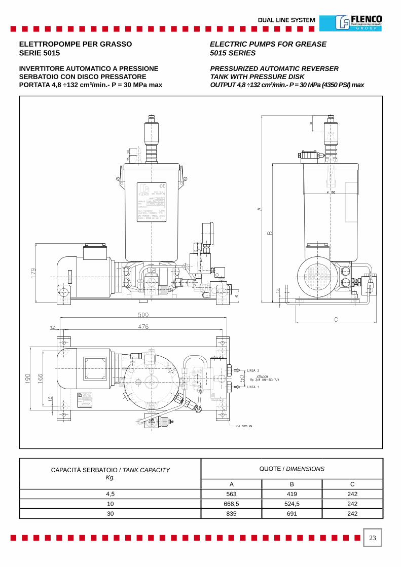
INVERTITORE AUTOMATICO A PRESSIONESERBATOIO CON DISCO PRESSATOREPORTATA 4,8 ÷132 cm3/min.- P = 30 MPa max
PRESSURIZED AUTOMATIC REVERSERTANK WITH PRESSURE DISKOUTPUT 4,8 ÷132 cm3/min.- P = 30 MPa (4350 PSI) max
CAPACITÀ SERBATOIO / TANK CAPACITYKg.
QUOTE / DIMENSIONS
A B C4,5 563 419 24210 668,5 524,5 24230 835 691 242

��
SISTEMA DOPPIA LINEA
ELETTROPOMPE PER GRASSOSERBATOI CON DISCO PRESSATORECAPACITÀ UTILE: 4,5 - 10 E 30 KgPortata al min/1’da 1,25 cm3 a 130 cm3- press. max fino a 100 MPa- numero delle mandate: da 1 a 4 regolabili singolarmente o a portata - portata fissa - possibilità di riunire le portate dei singoli pompanti in una sola uscita.
CARATTERISTICHE TECNICHE:- Motore elettrico trifase 220/380V 50 Hz / 4 poli - 0,18 kw IP 54 - Classe d’isolamento F- Rapporto di riduzione R = 1/15 e R= 1/30- Contatto elettrico di minimo livello sull’asta telescopica- Attacco mandate 1/4 BSP femmina- Attacco filettato 1/4 BSP femmina per eventuale ritorno in pompa- Filtro per riempimento serbatoio da 150 micron - attacco:1/2 BSP maschio oppure con testina idraulica a sfera- Serbatoi con disco pressatore - asta telescopica con indicatore visivo di minimo livello e indicatore visivo di max riempimento- Rete filtrante di protezione per ruotismi pompa
ACCESSORI POMPA- Pompanti a portata regolabile e a portata fissa- Invertitore automatico per doppia linea- Pressione max di inversione 30 MPa- Invertitore per doppia linea a comando elettrico per alta pressione- Invertitore elettropneumatico per doppia linea ad alta pressione- Valvola di regolazione pressione- Contatto elettrico di max riempimento per i serbatoi
PORTATA AL MIN/1’PER SINGOLO POMPANTE - R = 1/15Portata regolabile: min. 2,5 cm3 - max 18 cm3 - pompantecodice 7234005Portata regolabile: min. 4,8 cm3 - max 33 cm3 - pompantecodice 7234006Portata fissa: 18 cm3- pompante codice 7234025Portata fissa: 33 cm3- pompante codice 7234026
PORTATA AL MIN/1’PER SINGOLO POMPANTE - R = 1/30Portata regolabile: min.1,25 cm3 - max 9,5 cm3 - pompantecodice 7234005Portata regolabile:min.2,5 cm3 - max 17 cm3 - pompantecodice 7234006Portata fissa: 9,5 cm3- pompante codice 7234025Portata fissa: 17 cm3- pompante codice 7234026
PRESSIONI MAX DI ESERCIZIOCon 1 o 2 pompanti codice 7234005 o 7234025:Con pompa: R = 1/15 70 MpaCon pompa: R = 1/30 100 MPaCon 2 o 4 pompanti codice 7234005 o 7234025:Con pompa: R = 1/15 45 MpaCon pompa: R = 1/30 60 MPaCon 1 o 2 pompanti codice 7234006 o 7234026:Con pompa: R = 1/15 40 MpaCon pompa: R = 1/30 60 MPaCon 3 o 4 pompanti codice 7234006 o 7234026:Con pompa: R = 1/15 25 MpaCon pompa: R = 1/30 40 MPa
ELECTRIC PUMPS FOR GREASETANKS WITH PRESSURE DISKUSEFUL CAPACITY: Kg. 4,5 - 10 AND 30Output: from 1,25 cm3 to 130 cm3/min.- max. pressure up to 100 MPa (14500 PSI) - outlets number: from 1 to 4 singularly adjustable or with fix output - possibility to join the outputs of the single pumping elements in one outlet.
TECHNICAL CHARACTERISTICS:- Three-phase motor 220/380V 50Hz - 4 poles - Kw 0,18 IP 54 - isolation class F- Reduction ratio: R = 1/15 and R = 1/30- Minimum level electric contact on the telescopic pin- Delivery connection: 1/4 female BSP- Threaded connection 1/4 BSP female for the eventual return to the pump- Filter for tank filling: 150 micron - connection: 1/2 BSP male or with hydraulic ball head- Tanks completed by grease paddle and pressure disk - telescopic pin with minimum level visual indicator and max filling visual indicator- Filtering protective net for pump wheelworks
PUMP COMPONENTS- Pumping elements with adjustable or fix output- Automatic reverser for dual line- Reversing max pressure: 30 MPa (4350 PSI)- Automatic reverser for dual line, electric control for hight pressure- Electro-pneumatic reverser for dual line systems for hight pressures- Pressure adjustment valve- Tank max filling electric contact
PRIME OUTPUT FOR EACH PUMPING ELEMENT - R = 1/15Adjustable output: min.2,5 cm3 - max 18 cm3 - pumping elementcode 7234005Adjustable output: min.4,8 cm3 - max 33 cm3 - pumping elementcode 7234006Fix output: 18 cm3 - pumping element code 7234025Fix output: 33 cm3 - pumping element code 7234026
PRIME OUTPUT FOR EACH PUMPING ELEMENT - R = 1/30Adjustable output: min.1,25 cm3 - max 9,5 cm3 - pumping element code 7234005Adjustable output: min.2,5 cm3 - max 17 cm3 - pumping element code 7234006Fix output: 9,5 cm3 - pumping element code 7234025Fix output: 17 cm3 - pumping element code 7234026
MAX WORKING PRESSURESWith 1 or 2 pumping elements code 7234005 or 7234025:With pump: R - 1/15 70 Mpa (10150 PSI)With pump: R = 1/30 100 Mpa (14500 PSI)With 2 or 4 pumping elements code 7234005 or 7234025:With pump: R = 1/15 45 Mpa (6525) PSI)With pump R = 1/30 60 Mpa (8700 PSI)With 1 or 3 pumping elements code 7234006 or 7234026:With pump: R = 1/15 40 Mpa (5800 PSI)With pump R = 1/30 60 Mpa (8700 PSI)With 3 or 4 pumping elements code 7234006 or 7234026:With pump: R = 1/15 25 Mpa (3625 PSI)With pump R = 1/30 40 Mpa (5800 PSI)
ELETTROPOMPE PER GRASSO ELECTRIC PUMPSSERIE 5015 5015 SERIES FOR GREASE
��
DUAL LINE SYSTEM
CARATTERISTICHE TECNICHE:
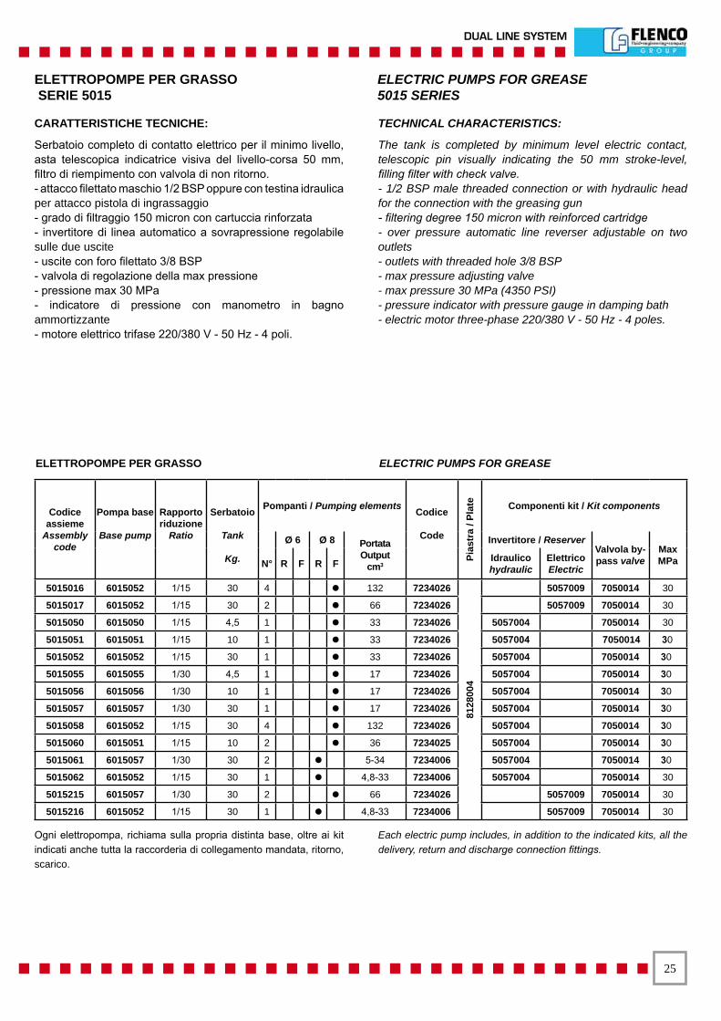
Serbatoio completo di contatto elettrico per il minimo livello, asta telescopica indicatrice visiva del livello-corsa 50 mm, filtro di riempimento con valvola di non ritorno.- attacco filettato maschio 1/2 BSP oppure con testina idraulica per attacco pistola di ingrassaggio- grado di filtraggio 150 micron con cartuccia rinforzata- invertitore di linea automatico a sovrapressione regolabile sulle due uscite- uscite con foro filettato 3/8 BSP- valvola di regolazione della max pressione- pressione max 30 MPa- indicatore di pressione con manometro in bagno ammortizzante- motore elettrico trifase 220/380 V - 50 Hz - 4 poli.
TECHNICAL CHARACTERISTICS:
The tank is completed by minimum level electric contact, telescopic pin visually indicating the 50 mm stroke-level, filling filter with check valve. - 1/2 BSP male threaded connection or with hydraulic head for the connection with the greasing gun- filtering degree 150 micron with reinforced cartridge- over pressure automatic line reverser adjustable on two outlets- outlets with threaded hole 3/8 BSP- max pressure adjusting valve- max pressure 30 MPa (4350 PSI)- pressure indicator with pressure gauge in damping bath- electric motor three-phase 220/380 V - 50 Hz - 4 poles.
ELETTROPOMPE PER GRASSO ELECTRIC PUMPS FOR GREASE SERIE 5015 5015 SERIES
ELETTROPOMPE PER GRASSO ELECTRIC PUMPS FOR GREASE
Codice assieme
Assembly code
Pompa base
Base pump
Rapportoriduzione
Ratio
Serbatoio
Tank
Kg.
Pompanti / Pumping elements Codice
Code
Pias
tra
/ Pla
te Componenti kit / Kit components
Ø 6 Ø 8 PortataOutput
cm3
Invertitore / ReserverValvola by-pass valve
MaxMPaN° R F R F Idraulico
hydraulicElettricoElectric
5015016 6015052 1/15 30 4 ● 132 7234026
8128
004
5057009 7050014 30
5015017 6015052 1/15 30 2 ● 66 7234026 5057009 7050014 30
5015050 6015050 1/15 4,5 1 ● 33 7234026 5057004 7050014 30
5015051 6015051 1/15 10 1 ● 33 7234026 5057004 7050014 30
5015052 6015052 1/15 30 1 ● 33 7234026 5057004 7050014 30
5015055 6015055 1/30 4,5 1 ● 17 7234026 5057004 7050014 30
5015056 6015056 1/30 10 1 ● 17 7234026 5057004 7050014 30
5015057 6015057 1/30 30 1 ● 17 7234026 5057004 7050014 30
5015058 6015052 1/15 30 4 ● 132 7234026 5057004 7050014 30
5015060 6015051 1/15 10 2 ● 36 7234025 5057004 7050014 30
5015061 6015057 1/30 30 2 ● 5-34 7234006 5057004 7050014 30
5015062 6015052 1/15 30 1 ● 4,8-33 7234006 5057004 7050014 30
5015215 6015057 1/30 30 2 ● 66 7234026 5057009 7050014 30
5015216 6015052 1/15 30 1 ● 4,8-33 7234006 5057009 7050014 30
Ogni elettropompa, richiama sulla propria distinta base, oltre ai kit indicati anche tutta la raccorderia di collegamento mandata, ritorno, scarico.
Each electric pump includes, in addition to the indicated kits, all the delivery, return and discharge connection fittings.
��
SISTEMA DOPPIA LINEA
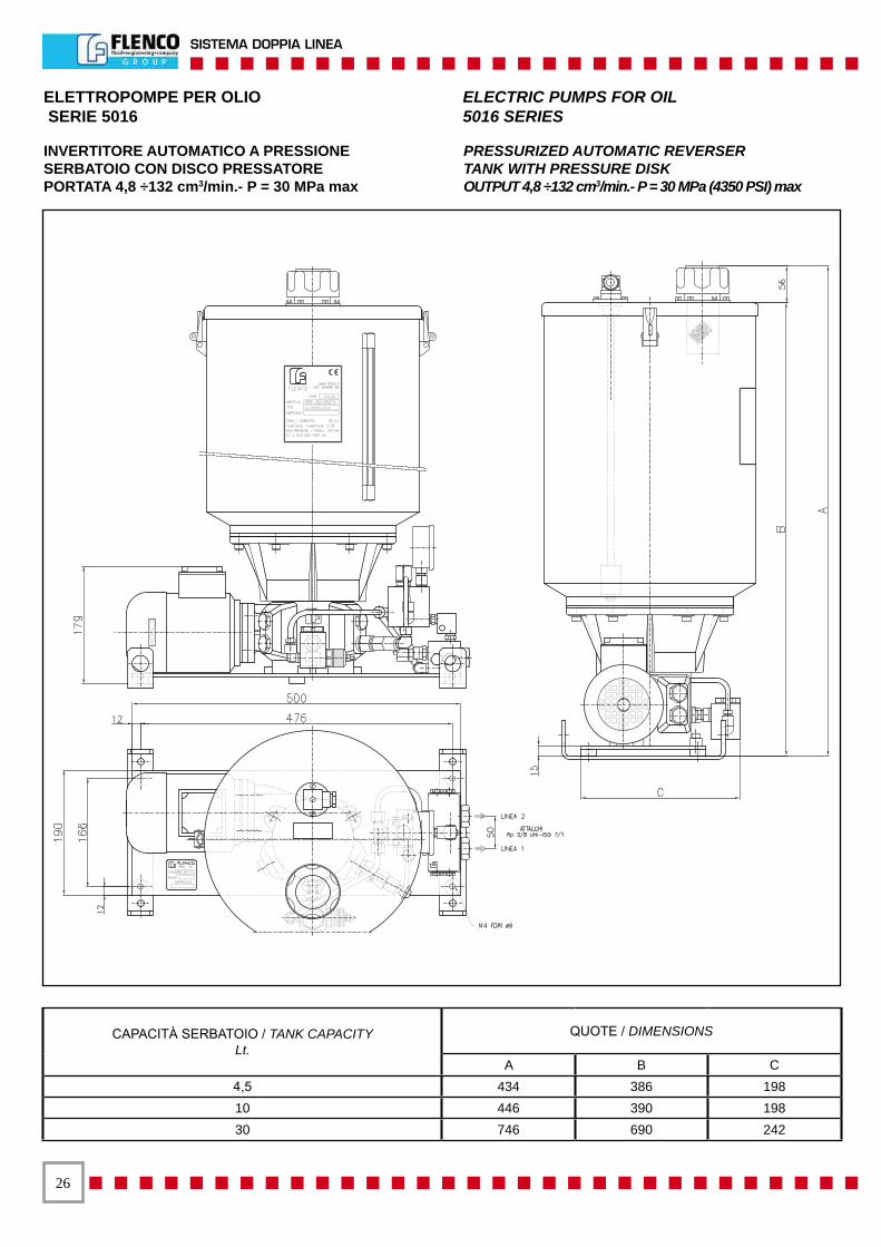
ELETTROPOMPE PER OLIO ELECTRIC PUMPS FOR OIL SERIE 5016 5016 SERIES
INVERTITORE AUTOMATICO A PRESSIONESERBATOIO CON DISCO PRESSATOREPORTATA 4,8 ÷132 cm3/min.- P = 30 MPa max
PRESSURIZED AUTOMATIC REVERSERTANK WITH PRESSURE DISKOUTPUT 4,8 ÷132 cm3/min.- P = 30 MPa (4350 PSI) max
CAPACITÀ SERBATOIO / TANK CAPACITYLt.
QUOTE / DIMENSIONS
A B C4,5 434 386 19810 446 390 19830 746 690 242

��
DUAL LINE SYSTEM
ELETTROPOMPE PER OLIOSERBATOI CON DISCO PRESSATORECAPACITÀ UTILE: 4,5 - 10 E 30 KgPortata al min/1’da 1,25 cm3 a 130 cm3- press. max fino a 100 MPa- numero delle mandate: da 1 a 4 regolabili singolarmente o a portata - portata fissa - possibilità di riunire le portate dei singoli pompanti in una sola uscita.
CARATTERISTICHE TECNICHE:- Motore elettrico trifase 220/380V 50 Hz / 4 poli - 0,18 kw IP 54 - Classe d’isolamento F- Rapporto di riduzione R = 1/15 e R= 1/30- Contatto elettrico di minimo livello sull’asta telescopica- Attacco mandate 1/4 BSP femmina- Attacco filettato 1/4 BSP femmina per eventuale ritorno in pompa- Filtro per riempimento serbatoio da 150 micron - attacco:1/2 BSP maschio oppure con testina idraulica a sfera- Serbatoi con disco pressatore - asta telescopica con indicatore visivo di minimo livello e indicatore visivo di max riempimento- Rete filtrante di protezione per ruotismi pompa.
ACCESSORI POMPA- Pompanti a portata regolabile e a portata fissa- Invertitore automatico per doppia linea- Pressione max di inversione 30 MPa- Invertitore per doppia linea a comando elettrico per alta pressione- Invertitore elettropneumatico per doppia linea ad alta pressione- Valvola di regolazione pressione- Contatto elettrico di max riempimento per i serbatoi
PORTATA AL MIN/1’PER SINGOLO POMPANTE - R = 1/15Portata regolabile: min. 2,5 cm3 - max 18 cm3 - pompantecodice 7234005Portata regolabile: min. 4,8 cm3 - max 33 cm3 - pompantecodice 7234006Portata fissa: 18 cm3- pompante codice 7234025Portata fissa: 33 cm3- pompante codice 7234026
PORTATA AL MIN/1’PER SINGOLO POMPANTE - R = 1/30Portata regolabile: min.1,25 cm3 - max 9,5 cm3 - pompantecodice 7234005Portata regolabile:min.2,5 cm3 - max 17 cm3 - pompantecodice 7234006Portata fissa: 9,5 cm3- pompante codice 7234025Portata fissa: 17 cm3- pompante codice 7234026
PRESSIONI MAX DI ESERCIZIOCon 1 o 2 pompanti codice 7234005 o 7234025:Con pompa: R = 1/15 70 MpaCon pompa: R = 1/30 100 MPaCon 2 o 4 pompanti codice 7234005 o 7234025:Con pompa: R = 1/15 45 MpaCon pompa: R = 1/30 60 MPaCon 1 o 2 pompanti codice 7234006 o 7234026:Con pompa: R = 1/15 40 MpaCon pompa: R = 1/30 60 MPaCon 3 o 4 pompanti codice 7234006 o 7234026:Con pompa: R = 1/15 25 MpaCon pompa: R = 1/30 40 MPa
ELECTRIC PUMPS FOR OILTANKS WITH PRESSURE DISKUSEFUL CAPACITY: Kg. 4,5 - 10 AND 30Output: from 1,25 cm3 to 130 cm3/min.- max. pressure up to 100 MPa (14500 PSI) - outlets number: from 1 to 4 singularly adjustable or with fix output - possibility to join the outputs of the single pumping elements in one outlet.
TECHNICAL CHARACTERISTICS:- Three-phase motor 220/380V 50Hz - 4 poles - Kw 0,18 IP 54 - isolation class F- Reduction ratio: R = 1/15 and R = 1/30- Minimum level electric contact on the telescopic pin- Delivery connection: 1/4 female BSP- Threaded connection 1/4 BSP female for the eventual return to the pump- Filter for tank filling: 150 micron - connection: 1/2 BSP male or with hydraulic ball head- Tanks completed by grease paddle and pressure disk - telescopic pin with minimum level visual indicator and max filling visual indicator- Filtering protective net for pump wheelworks.
PUMP COMPONENTS- Pumping elements with adjustable or fix output- Automatic reverser for dual line- Reversing max pressure: 30 MPa (4350 PSI)- Automatic reverser for dual line, electric control for hight pressure- Electro-pneumatic reverser for dual line systems for hight pressures- Pressure adjustment valve- Tank max filling electric contact
PRIME OUTPUT FOR EACH PUMPING ELEMENT - R = 1/15Adjustable output: min.2,5 cm3 - max 18 cm3 - pumping elementcode 7234005Adjustable output: min.4,8 cm3 - max 33 cm3 - pumping elementcode 7234006Fix output: 18 cm3 - pumping element code 7234025Fix output: 33 cm3 - pumping element code 7234026
PRIME OUTPUT FOR EACH PUMPING ELEMENT - R = 1/30Adjustable output: min.1,25 cm3 - max 9,5 cm3 - pumping element code 7234005Adjustable output: min.2,5 cm3 - max 17 cm3 - pumping element code 7234006Fix output: 9,5 cm3 - pumping element code 7234025Fix output: 17 cm3 - pumping element code 7234026
MAX WORKING PRESSURESWith 1 or 2 pumping elements code 7234005 or 7234025:With pump: R - 1/15 70 Mpa (10150 PSI)With pump: R = 1/30 100 Mpa (14500 PSI)With 2 or 4 pumping elements code 7234005 or 7234025:With pump: R = 1/15 45 Mpa (6525) PSI)With pump R = 1/30 60 Mpa (8700 PSI)With 1 or 3 pumping elements code 7234006 or 7234026:With pump: R = 1/15 40 Mpa (5800 PSI)With pump R = 1/30 60 Mpa (8700 PSI)With 3 or 4 pumping elements code 7234006 or 7234026:With pump: R = 1/15 25 Mpa (3625 PSI)With pump R = 1/30 40 Mpa (5800 PSI)
ELETTROPOMPE PER OLIO ELECTRIC PUMPSSERIE 5016 5016 SERIES FOR OIL
��
SISTEMA DOPPIA LINEA
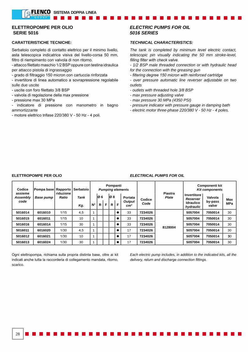
ELETTROPOMPE PER OLIO ELECTRICAL PUMPS FOR OIL
Codice assieme
Assembly code
Pompa base
Base pump
Rapportoriduzione
Ratio
Serbatoio
Tank
Kg.
PompantiPumping elements
PiastraPlate
Componenti kitKit components
Ø 6 Ø 8 Portata Output
cm3
Codice Code
InvertitoreReserver Valvola
by-passvalve
Max MPaN° R F R F Idraulico
hydraulic5016014 6016010 1/15 4,5 1 ● 33 7234026
8128004
5057004 7050014 30
5016015 6016011 1/15 10 1 ● 33 7234026 5057004 7050014 30
5016016 6016014 1/15 30 1 ● 33 7234026 5057004 7050014 30
5016011 6016020 1/30 4,5 1 ● 17 7234026 5057004 7050014 30
5016012 6016021 1/30 10 1 ● 17 7234026 5057004 7050014 30
5016013 6016024 1/30 30 1 ● 17 7234026 5057004 7050014 30
CARATTERISTICHE TECNICHE:
Serbatoio completo di contatto elettrico per il minimo livello, asta telescopica indicatrice visiva del livello-corsa 50 mm, filtro di riempimento con valvola di non ritorno.- attacco filettato maschio 1/2 BSP oppure con testina idraulica per attacco pistola di ingrassaggio- grado di filtraggio 150 micron con cartuccia rinforzata- invertitore di linea automatico a sovrapressione regolabile sulle due uscite- uscite con foro filettato 3/8 BSP- valvola di regolazione della max pressione- pressione max 30 MPa- indicatore di pressione con manometro in bagno ammortizzante- motore elettrico trifase 220/380 V - 50 Hz - 4 poli.
TECHNICAL CHARACTERISTICS:
The tank is completed by minimum level electric contact, telescopic pin visually indicating the 50 mm stroke-level, filling filter with check valve.- 1/2 BSP male threaded connection or with hydraulic head for the connection with the greasing gun- filtering degree 150 micron with reinforced cartridge- over pressure automatic line reverser adjustable on two outlets- outlets with threaded hole 3/8 BSP- max pressure adjusting valve- max pressure 30 MPa (4350 PSI)- pressure indicator with pressure gauge in damping bath- electric motor three-phase 220/380 V - 50 Hz - 4 poles.
ELETTROPOMPE PER OLIO ELECTRIC PUMPS FOR OIL SERIE 5016 5016 SERIES
Ogni elettropompa, richiama sulla propria distinta base, oltre ai kit indicati anche tutta la raccorderia di collegamento mandata, ritorno, scarico.
Each electric pump includes, in addition to the indicated kits, all the delivery, return and discharge connection fittings.
��
DUAL LINE SYSTEM
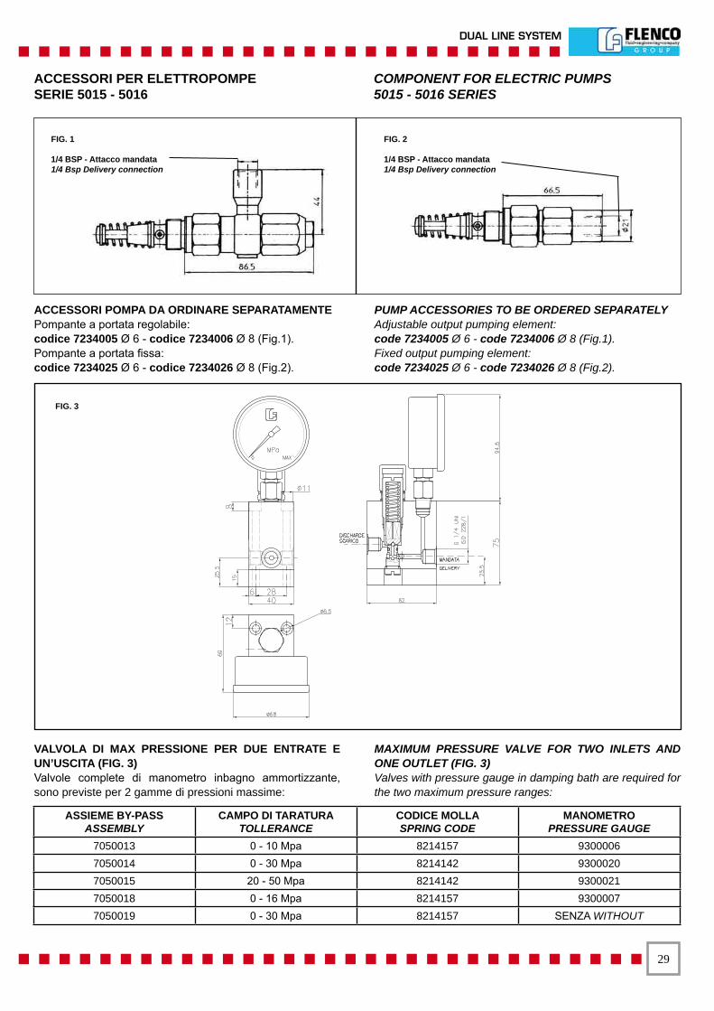
ACCESSORI PER ELETTROPOMPE COMPONENT FOR ELECTRIC PUMPSSERIE 5015 - 5016 5015 - 5016 SERIES
ACCESSORI POMPA DA ORDINARE SEPARATAMENTEPompante a portata regolabile:codice 7234005 Ø 6 - codice 7234006 Ø 8 (Fig.1).Pompante a portata fissa:codice 7234025 Ø 6 - codice 7234026 Ø 8 (Fig.2).
PUMP ACCESSORIES TO BE ORDERED SEPARATELYAdjustable output pumping element:code 7234005 Ø 6 - code 7234006 Ø 8 (Fig.1).Fixed output pumping element:code 7234025 Ø 6 - code 7234026 Ø 8 (Fig.2).
VALVOLA DI MAX PRESSIONE PER DUE ENTRATE E UN’USCITA (FIG. 3)Valvole complete di manometro inbagno ammortizzante, sono previste per 2 gamme di pressioni massime:
MAXIMUM PRESSURE VALVE FOR TWO INLETS AND ONE OUTLET (FIG. 3)Valves with pressure gauge in damping bath are required for the two maximum pressure ranges:
ASSIEME BY-PASSASSEMBLY
CAMPO DI TARATURATOLLERANCE
CODICE MOLLASPRING CODE
MANOMETROPRESSURE GAUGE
7050013 0 - 10 Mpa 8214157 93000067050014 0 - 30 Mpa 8214142 93000207050015 20 - 50 Mpa 8214142 93000217050018 0 - 16 Mpa 8214157 93000077050019 0 - 30 Mpa 8214157 SENZA WITHOUT
FIG. 2
1/4 BSP - Attacco mandata1/4 Bsp Delivery connection
FIG. 1
1/4 BSP - Attacco mandata1/4 Bsp Delivery connection
FIG. 3
�0
SISTEMA DOPPIA LINEA
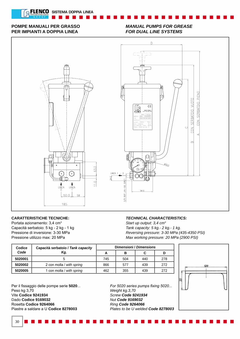
POMPE MANUALI PER GRASSO MANUAL PUMPS FOR GREASEPER IMPIANTI A DOPPIA LINEA FOR DUAL LINE SYSTEMS
CARATTERISTICHE TECNICHE:Portata azionamento: 3,4 cm3
Capacità serbatoio: 5 kg - 2 kg - 1 kgPressione di inversione: 3-30 MPaPressione utilizzo max: 20 MPa
TECHNICAL CHARACTERISTICS:Start up output: 3,4 cm3
Tank capacity: 5 kg.- 2 kg.- 1 kg.Reversing pressure: 3-30 MPa (435-4350 PSI)Max working pressure: 20 MPa (2900 PSI)
Codice Code
Capacità serbatoio / Tank capacityKg.
Dimensioni / DimensionsA B C D
5020001 5 745 504 440 2785020002 2 con molla / with spring 866 577 439 2725020005 1 con molla / with spring 462 355 439 272
Per il fissaggio delle pompe serie 5020...Peso kg 3,70Vite Codice 9241934Dado Codice 9169032Rosetta Codice 9264066Piastre a saldare a U Codice 8278003
For 5020 series pumps fixing 5020...Weight kg.3,70Screw Code 9241934Nut Code 9169032Ring Code 9264066Plates to be U welded Code 8278003
��
DUAL LINE SYSTEM
ACCESSORI
COMPONENTS
��
SISTEMA DOPPIA LINEA
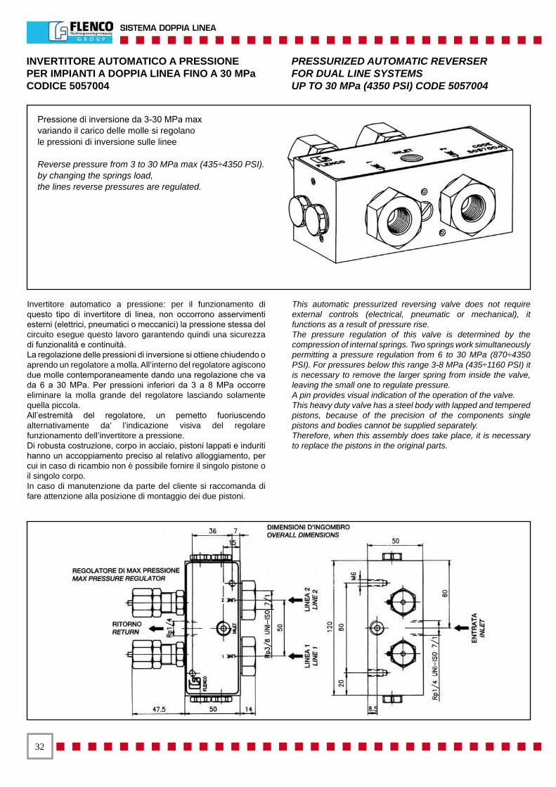
Invertitore automatico a pressione: per il funzionamento di questo tipo di invertitore di linea, non occorrono asservimenti esterni (elettrici, pneumatici o meccanici) la pressione stessa del circuito esegue questo lavoro garantendo quindi una sicurezza di funzionalità e continuità.La regolazione delle pressioni di inversione si ottiene chiudendo o aprendo un regolatore a molla. All’interno del regolatore agiscono due molle contemporaneamente dando una regolazione che va da 6 a 30 MPa. Per pressioni inferiori da 3 a 8 MPa occorre eliminare la molla grande del regolatore lasciando solamente quella piccola.All’estremità del regolatore, un pernetto fuoriuscendo alternativamente da’ l’indicazione visiva del regolare funzionamento dell’invertitore a pressione.Di robusta costruzione, corpo in acciaio, pistoni lappati e induriti hanno un accoppiamento preciso al relativo alloggiamento, per cui in caso di ricambio non è possibile fornire il singolo pistone o il singolo corpo.In caso di manutenzione da parte del cliente si raccomanda di fare attenzione alla posizione di montaggio dei due pistoni.
This automatic pressurized reversing valve does not require external controls (electrical, pneumatic or mechanical), it functions as a result of pressure rise.The pressure regulation of this valve is determined by the compression of internal springs. Two springs work simultaneously permitting a pressure regulation from 6 to 30 MPa (870÷4350 PSI). For pressures below this range 3-8 MPa (435÷1160 PSI) it is necessary to remove the larger spring from inside the valve, leaving the small one to regulate pressure.A pin provides visual indication of the operation of the valve.This heavy duty valve has a steel body with lapped and tempered pistons, because of the precision of the components single pistons and bodies cannot be supplied separately.Therefore, when this assembly does take place, it is necessary to replace the pistons in the original parts.
Pressione di inversione da 3-30 MPa maxvariando il carico delle molle si regolanole pressioni di inversione sulle linee
Reverse pressure from 3 to 30 MPa max (435÷4350 PSI).by changing the springs load,the lines reverse pressures are regulated.
INVERTITORE AUTOMATICO A PRESSIONE PER IMPIANTI A DOPPIA LINEA FINO A 30 MPaCODICE 5057004
PRESSURIZED AUTOMATIC REVERSERFOR DUAL LINE SYSTEMSUP TO 30 MPa (4350 PSI) CODE 5057004
��
DUAL LINE SYSTEM
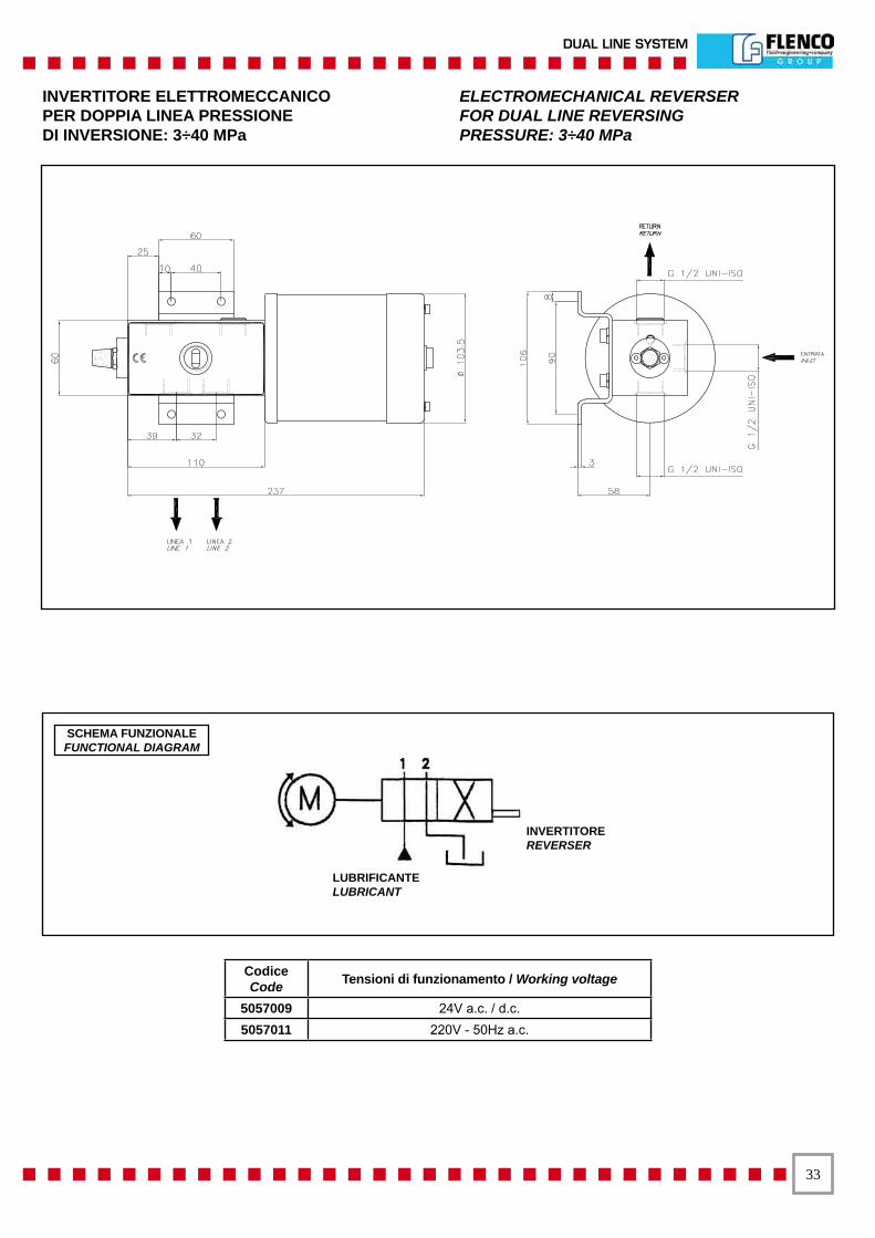
INVERTITORE ELETTROMECCANICOPER DOPPIA LINEA PRESSIONEDI INVERSIONE: 3÷40 MPa
ELECTROMECHANICAL REVERSERFOR DUAL LINE REVERSINGPRESSURE: 3÷40 MPa
CodiceCode Tensioni di funzionamento / Working voltage
5057009 24V a.c. / d.c.5057011 220V - 50Hz a.c.
INVERTITOREREVERSER
LUBRIFICANTELUBRICANT
SCHEMA FUNZIONALEFUNCTIONAL DIAGRAM
��
SISTEMA DOPPIA LINEA
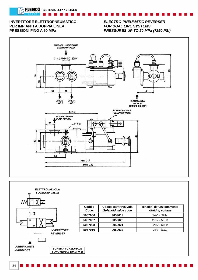
INVERTITORE ELETTROPNEUMATICOPER IMPIANTI A DOPPIA LINEAPRESSIONI FINO A 50 MPa
ELECTRO-PNEUMATIC REVERSERFOR DUAL LINE SYSTEMSPRESSURES UP TO 50 MPa (7250 PSI)
CodiceCode
Codice elettrovalvolaSolenoid valve code
Tensioni di funzionamentoWorking voltage
5057006 9059019 24V - 50Hz 5057007 9059020 110V - 50Hz 5057008 9059021 220V - 50Hz 5057010 9059033 24V - D.C. INVERTITORE
REVERSER
LUBRIFICANTELUBRICANT
ELETTROVALVOLASOLENOID VALVE
SCHEMA FUNZIONALEFUNCTIONAL DIAGRAM
��
DUAL LINE SYSTEM
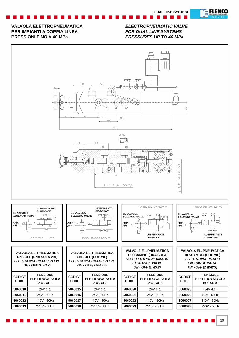
VALVOLA ELETTROPNEUMATICAPER IMPIANTI A DOPPIA LINEA PRESSIONI FINO A 40 MPa
ELECTROPNEUMATIC VALVEFOR DUAL LINE SYSTEMSPRESSURES UP TO 40 MPa
VALVOLA EL. PNEUMATICA ON - OFF (UNA SOLA VIA)
ELECTROPNEUMATIC VALVE ON - OFF (1 WAY)
CODICE CODE
TENSIONE ELETTROVALVOLA
VOLTAGE
5060010 24V d.c.
5060011 24V - 50Hz
5060012 110V - 50Hz
5060013 220V - 50Hz
VALVOLA EL. PNEUMATICA ON - OFF (DUE VIE)
ELECTROPNEUMATIC VALVE ON - OFF (2 WAYS)
CODICE CODE
TENSIONE ELETTROVALVOLA
VOLTAGE
5060015 24V d.c.
5060016 24V - 50Hz
5060017 110V - 50Hz
5060018 220V - 50Hz
VALVOLA EL. PNEUMATICA DI SCAMBIO (UNA SOLA
VIA) ELECTROPNEUMATIC EXCHANGE VALVEON - OFF (1 WAY)
CODICE CODE
TENSIONE ELETTROVALVOLA
VOLTAGE
5060020 24V d.c.
5060021 24V - 50Hz
5060022 110V - 50Hz
5060023 220V - 50Hz
VALVOLA EL. PNEUMATICA DI SCAMBIO (DUE VIE) ELECTROPNEUMATIC
EXCHANGE VALVEON - OFF (2 WAYS)
CODICE CODE
TENSIONE ELETTROVALVOLA
VOLTAGE
5060025 24V d.c.
5060026 24V - 50Hz
5060027 110V - 50Hz
5060028 220V - 50Hz
EL VALVOLASOLENOID VALVE
LUBRIFICANTELUBRICANT
ARIAAIR
EL VALVOLASOLENOID VALVE
LUBRIFICANTELUBRICANT
ARIAAIR
EL VALVOLASOLENOID VALVE
LUBRIFICANTELUBRICANT
ARIAAIR
EL VALVOLASOLENOID VALVE
LUBRIFICANTELUBRICANT
ARIAAIR
��
SISTEMA DOPPIA LINEA
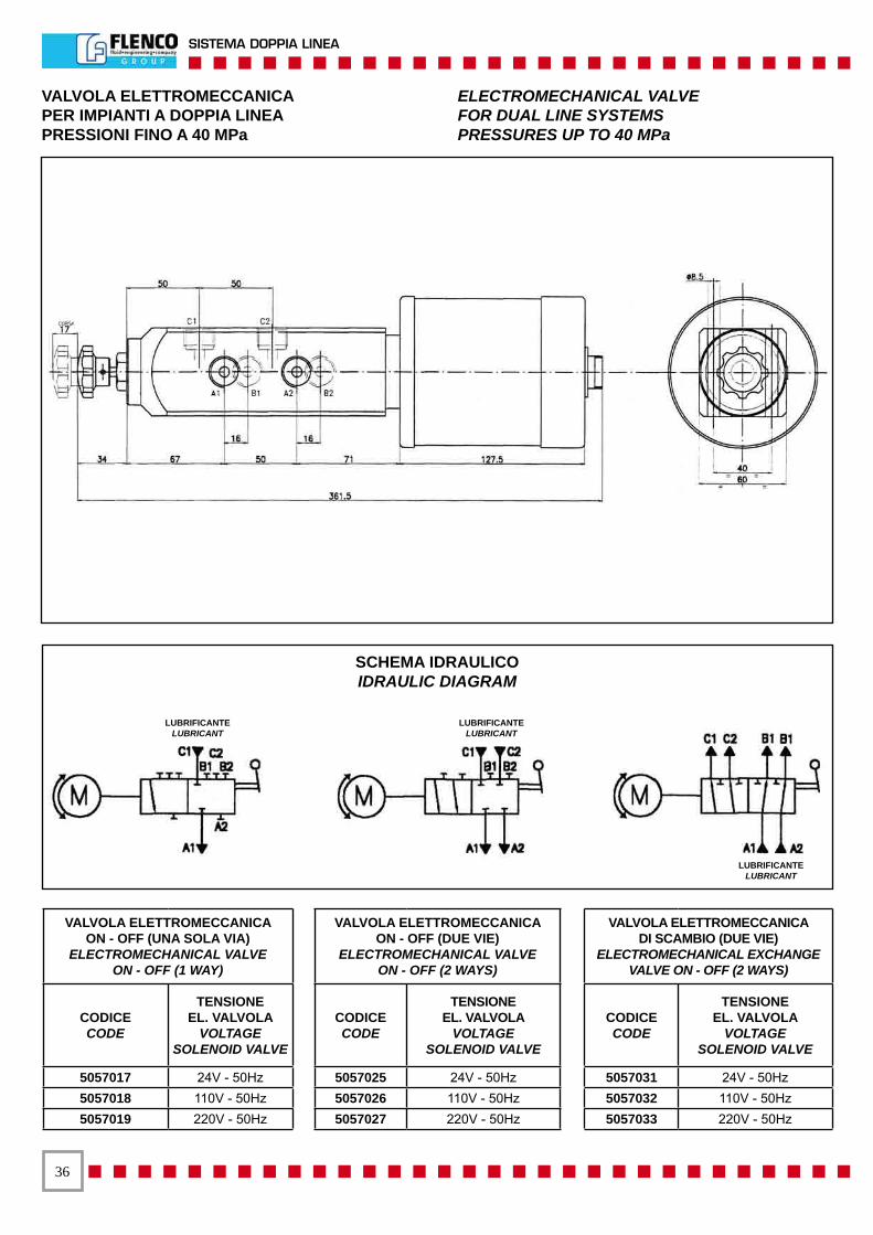
VALVOLA ELETTROMECCANICAPER IMPIANTI A DOPPIA LINEAPRESSIONI FINO A 40 MPa
ELECTROMECHANICAL VALVEFOR DUAL LINE SYSTEMSPRESSURES UP TO 40 MPa
VALVOLA ELETTROMECCANICA ON - OFF (UNA SOLA VIA)
ELECTROMECHANICAL VALVEON - OFF (1 WAY)
CODICECODE
TENSIONE EL. VALVOLA
VOLTAGESOLENOID VALVE
5057017 24V - 50Hz 5057018 110V - 50Hz 5057019 220V - 50Hz
VALVOLA ELETTROMECCANICA ON - OFF (DUE VIE)
ELECTROMECHANICAL VALVEON - OFF (2 WAYS)
CODICE CODE
TENSIONEEL. VALVOLA
VOLTAGE SOLENOID VALVE
5057025 24V - 50Hz 5057026 110V - 50Hz 5057027 220V - 50Hz
VALVOLA ELETTROMECCANICA DI SCAMBIO (DUE VIE)
ELECTROMECHANICAL EXCHANGE VALVE ON - OFF (2 WAYS)
CODICE CODE
TENSIONEEL. VALVOLA
VOLTAGESOLENOID VALVE
5057031 24V - 50Hz 5057032 110V - 50Hz 5057033 220V - 50Hz
SCHEMA IDRAULICOIDRAULIC DIAGRAM
LUBRIFICANTELUBRICANT
LUBRIFICANTELUBRICANT
LUBRIFICANTELUBRICANT
��
DUAL LINE SYSTEM
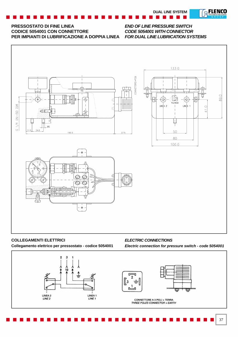
PRESSOSTATO DI FINE LINEACODICE 5054001 CON CONNETTOREPER IMPIANTI DI LUBRIFICAZIONE A DOPPIA LINEA
END OF LINE PRESSURE SWITCHCODE 5054001 WITH CONNECTORFOR DUAL LINE LUBRICATION SYSTEMS
COLLEGAMENTI ELETTRICICollegamento elettrico per pressostato - codice 5054001
ELECTRIC CONNECTIONSElectric connection for pressure switch - code 5054001
��
SISTEMA DOPPIA LINEA
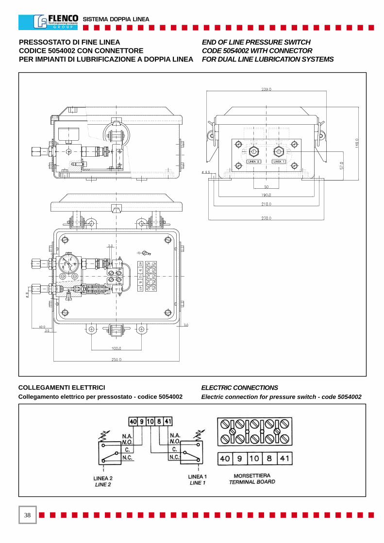
PRESSOSTATO DI FINE LINEACODICE 5054002 CON CONNETTOREPER IMPIANTI DI LUBRIFICAZIONE A DOPPIA LINEA
END OF LINE PRESSURE SWITCHCODE 5054002 WITH CONNECTORFOR DUAL LINE LUBRICATION SYSTEMS
COLLEGAMENTI ELETTRICICollegamento elettrico per pressostato - codice 5054002
ELECTRIC CONNECTIONSElectric connection for pressure switch - code 5054002

��
DUAL LINE SYSTEM
APPARECCHIATURA ELETTRICACODICE 5011086
ELECTRICAL EQUIPMENTCODE 5011086
CARATTERISTICHE TECNICHE:- Tensione primaria: 220/380/400/415 V - 50 Hz.- Tensione secondaria: 24 V - 50 Hz.- Grado di protezione: IP 55
Apparecchiatura predisposta per il comando ed il controllo delle elettropompe tipo: FX2 / 5015 / 6015 con invertitore elettromeccanico, elettropneumatico.
DESCRIZIONE DI FUNZIONAMENTO:1) Temporizzatore elettronico digitale, teleruttore con protezione termica per il controllo del motore.2) Controllo dei tempi di ciclo, segnalazione di minimo e massimo livello, possibilità di controllo remoto e predisposizione per il caricamento automatico.3) Dispositivo per il controllo del ciclo di lubrificazione tramite l’impiego dei pressostati di fine linea.4) Il modo pausa può essere a tempo o ad impulsi.
TECHNICAL CHARACTERISTICS:- Primary voltage: 220/380/400/415 V - 50 Hz.- Secondary voltage: 24 V - 50 Hz.- Protection rating: IP 55
Electrical equipment for the command and control of the electric pumps series: FX2 / 5015 / 6015 equipped with electromechanical and electropneumatic reverser.
OPERATION DESCRIPTION:1) Electronic digital timer, starter with thermal protection for motor control. 2) Cycle time control, minimum and maximum level signal, remote control available and arrangement of automatic load. 3) Device for control of lubrication cycle by end of line pressure switch. 4) Pause mode: time or impulses.
�0
SISTEMA DOPPIA LINEA
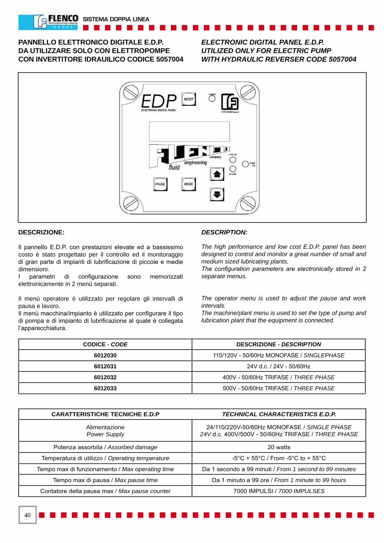
PANNELLO ELETTRONICO DIGITALE E.D.P.DA UTILIZZARE SOLO CON ELETTROPOMPECON INVERTITORE IDRAUILICO CODICE 5057004
ELECTRONIC DIGITAL PANEL E.D.P. UTILIZED ONLY FOR ELECTRIC PUMP WITH HYDRAULIC REVERSER CODE 5057004
DESCRIZIONE:
Il pannello E.D.P. con prestazioni elevate ed a bassissimo costo è stato progettato per il controllo ed il monitoraggio di gran parte di impianti di lubrificazione di piccole e medie dimensioni.I parametri di configurazione sono memorizzati elettronicamente in 2 menù separati.
Il menù operatore è utilizzato per regolare gli intervalli di pausa e lavoro.Il menù macchina/impianto è utilizzato per configurare il tipo di pompa e di impianto di lubrificazione al quale è collegata l’apparecchiatura.
DESCRIPTION:
The high performance and low cost E.D.P. panel has been designed to control and monitor a great number of small and medium sized lubricating plants.The configuration parameters are electronically stored in 2 separate menus.
The operator menu is used to adjust the pause and work intervals.The machine/plant menu is used to set the type of pump andlubrication plant that the equipment is connected.
CODICE - CODE DESCRIZIONE - DESCRIPTION
6012030 110/120V - 50/60Hz MONOFASE / SINGLEPHASE
6012031 24V d.c. / 24V - 50/60Hz
6012032 400V - 50/60Hz TRIFASE / THREE PHASE
6012033 500V - 50/60Hz TRIFASE / THREE PHASE
CARATTERISTICHE TECNICHE E.D.P TECHNICAL CHARACTERISTICS E.D.P.
AlimentazionePower Supply
24/110/220V-50/60Hz MONOFASE / SINGLE PHASE24V d.c. 400V/500V - 50/60Hz TRIFASE / THREE PHASE
Potenza assorbita / Assorbed damage 20 watts
Temperatura di utilizzo / Operating temperature -5°C + 55°C / From -5°C to + 55°C
Tempo max di funzionamento / Max operating time Da 1 secondo a 99 minuti / From 1 second to 99 minutes
Tempo max di pausa / Max pause time Da 1 minuto a 99 ore / From 1 minute to 99 hours
Contatore della pausa max / Max pause counter 7000 IMPULSI / 7000 IMPULSES
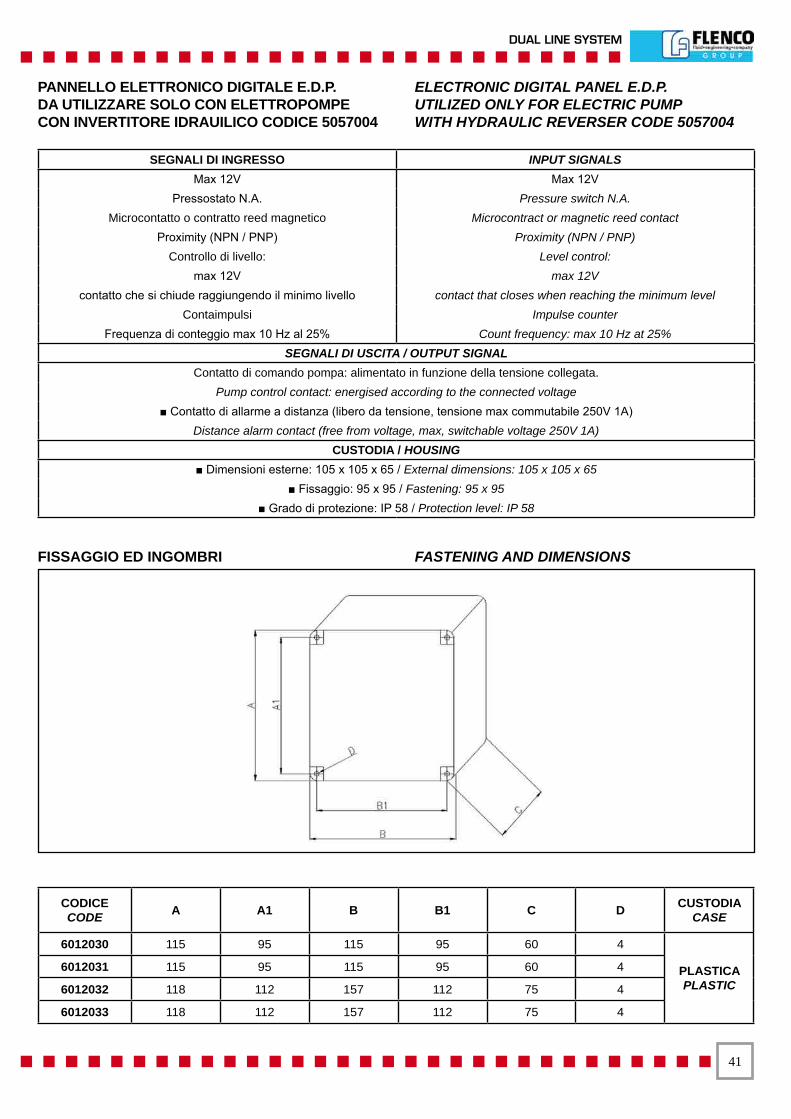
��
DUAL LINE SYSTEM
SEGNALI DI INGRESSO INPUT SIGNALSMax 12V Max 12V
Pressostato N.A. Pressure switch N.A.Microcontatto o contratto reed magnetico Microcontract or magnetic reed contact
Proximity (NPN / PNP) Proximity (NPN / PNP)Controllo di livello: Level control:
max 12V max 12Vcontatto che si chiude raggiungendo il minimo livello contact that closes when reaching the minimum level
Contaimpulsi Impulse counterFrequenza di conteggio max 10 Hz al 25% Count frequency: max 10 Hz at 25%
SEGNALI DI USCITA / OUTPUT SIGNAL Contatto di comando pompa: alimentato in funzione della tensione collegata.
Pump control contact: energised according to the connected voltage ■ Contatto di allarme a distanza (libero da tensione, tensione max commutabile 250V 1A)
Distance alarm contact (free from voltage, max, switchable voltage 250V 1A) CUSTODIA / HOUSING
■ Dimensioni esterne: 105 x 105 x 65 / External dimensions: 105 x 105 x 65 ■ Fissaggio: 95 x 95 / Fastening: 95 x 95
■ Grado di protezione: IP 58 / Protection level: IP 58
FISSAGGIO ED INGOMBRI FASTENING AND DIMENSIONS
CODICECODE A A1 B B1 C D CUSTODIA
CASE
6012030 115 95 115 95 60 4
PLASTICAPLASTIC
6012031 115 95 115 95 60 4
6012032 118 112 157 112 75 4
6012033 118 112 157 112 75 4
PANNELLO ELETTRONICO DIGITALE E.D.P.DA UTILIZZARE SOLO CON ELETTROPOMPECON INVERTITORE IDRAUILICO CODICE 5057004
ELECTRONIC DIGITAL PANEL E.D.P. UTILIZED ONLY FOR ELECTRIC PUMP WITH HYDRAULIC REVERSER CODE 5057004
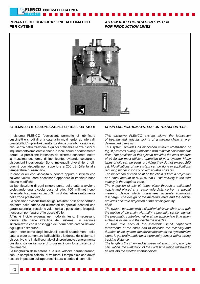
��
SISTEMA DOPPIA LINEA
IMPIANTO DI LUBRIFICAZIONE AUTOMATICOPER CATENE
AUTOMATIC LUBRICATION SYSTEMFOR PRODUCTION LINES
SISTEMA LUBRIFICAZIONE CATENE PER TRASPORTATORI
Il sistema FLENCO (esclusivo), permette di lubrificare cuscinetti e snodi di una catena in movimento, ad intervalli prestabiliti. L’impianto è caratterizzato da una lubrificazione ad olio, senza nebulizzazione e quindi praticabile senza rischi di inquinamento ambientale anche in locali chiusi e scarsamente aerati. La precisione intrinseca del sistema consente inoltre la massima economia di lubrificante, evitando colature e dispersioni indesiderate. Sono impiegabili diversi tipi di olii, purché con viscosità non superiore a 200 cSt (riferita alla temperatura di esercizio).In caso di olii con viscosità superiore oppure fluidificati con solventi volatili, sarà necessario apportare all’impianto base alcune modifiche.La lubrificazione di ogni singolo punto della catena avviene proiettando una piccola dose di olio, 100 millimetri cubi (equivalenti ad una goccia di 3 mm di diametro) esattamente nella zona prestabilita.La proiezione avviene tramite ugelli calibrati posti ad opportuna distanza dalla catena ed alimentati da speciali dosatori che garantiscono la precisione volumetrica e possiedono i requisiti necessari per “sparare” le gocce d’olio.Affinché il ciclo avvenga nel modo richiesto, è necessario fornire alla parte idraulica del sistema, un segnale sincronizzato con il passaggio dei perni della catena davanti agli ugelli distributori.Onde tener conto degli inevitabili piccoli sbandamenti della catena e per aumentare l’affidabilità e la durata del sistema, il dispositivo che invia il segnale di sincronismo è generalmente costituito da un sensore di prossimità con forte distanza di rilevamento.La lunghezza della catena e la sua velocità permetteranno, con un semplice calcolo, di valutare il tempo ciclo che dovrà essere impostato sull’apparecchiatura elettrica di controllo.
CHAIN LUBRICATION SYSTEM FOR TRANSPORTERS
This exclusive FLENCO system allows the lubrication of bearing and articular points of a moving chain at pre-determined intervals.This system provides oil lubrication without atomization or fog. It provides quality lubrication with minimal environmental risks. The precision of this system provides the least amount of oil for the most efficient operation of your system. Many types of oils can be used, providing they do not exceed 200 cst. Modifications of the system can be done in applications requiring higher viscosity or with volatile solvents.The lubrication of each point on the chain is from a projection of a small amount of oil (0,01 cm3). The delivery is focused exactly in the required zone.The projection of this oil takes place through a calibrated nozzle and placed at a reasonable distance from a special metering device which guarantees accurate volumetric discharge. The design of the metering valve and the nozzle provides accurate projection of this small quantityof oil.The system operates with a signal which is synchronized with the motion of the chain. Normally, a proximity sensor signals the pneumatic controlling valve at the appropriate time when a chain is in line with the discharge nozzles.To take into account the inevitable small haphazard movements of the chain and to increase the reliability and duration of the system, the device that sends the synchronism signal is generally made up of a proximity sensor with a strong tracking distance.The length of the chain and its speed will allow, using a simple calculation, the evaluation of the cycle time which will have to be fed into the electric control device.
��
DUAL LINE SYSTEM
IMPIANTO DI LUBRIFICAZIONE AUTOMATICOPER CATENE
AUTOMATIC LUBRICATION SYSTEMFOR PRODUCTION LINES
COMPONENTI NECESSARIPER REALIZZARE L’IMPIANTO
1) Centralina comprendente:- vasca in acciaio con capacità di 60 litri;- segnalatore elettrico di livello minimo (contatto normalmente chiuso);- indicatore di livello visivo;- tappo di riempimento con filtro;- n. 2 pompe pneumatiche “FLENCO” con portata 4 cm3/impulso;- manometro per lettura pressione in uscita dalle pompe;- gruppo trattamento aria compressa con manometro;- elettrovalvola azionamento pompe;- valvola a scarico rapido;il tutto assiemato.
2) Dosatore 100 mm3 (uno per ogni punto da lubrificare).
3) Tubo capillare Ø 4 lunghezza 500 mm con ugello calibrato(uno per ogni punto da lubrificare).Il tubo capillare dovrà essere modellato inopera in modo da orientare l’ugello verso il punto sul quale occorre proiettare la goccia (cuscinetto, snodo, ecc.).
4) Apparecchiatura elettrica di comando e controllo(secondo norme FIAT) comprendente:- trasformatore con primario 500 volt e secondario 110 volt;- temporizzatore 0-24 ore per programmazione tempo ciclo;- temporizzatore 0-24 ore per programmazione tempo pausa;- dispositivi d’interfaccia tra sensore di posizione ed elettrovalvola;- segnalatore di allarme (Rotallarm) asservito al livello minimo olio nella centralina;- spie luminose di funzionamento e controllo; il tutto assiemato.
INSTALLAZIONE DELL’IMPIANTO
- Individuare, su un passo qualsiasi della catena, dopo averne arrestato il movimento, i punti che richiedono lubrificazione. (Abitualmente, la lubrificazione viene effettuata su un solo passo per volta).- Scegliere una posizione in cui la catena sia ben guidata ed abbia quindi le minime possibilità di spostarsi trasversalmente (sia in senso orizzontale che verticale).- Posizionare e fissare il primo dosatore, con relativo tubo capillare ed ugello, in modo che l’ugello si trovi il più vicino possibile al punto da lubrificare. Durante questa fase, accertarsi che lo sbandamento della catena non porti questa ad interferire con l’ugello.- Ripetere l’operazione precedente per tutti i punti da lubrificare.- In corrispondenza del passo catena precedente a quello sul quale sono stati indirizzati gli ugelli, posizionare e fissare il sensore di prossimità in modo che risulti azionato. (Anche in questo caso tener conto dello sbandamento che può subire la catena). La centralina non dovrà essere ad oltre 18 metri di distanza dalla zona lubrificata.Se l’installazione è stata compiuta a dovere, in particolare, per quanto concerne il sensore di prossimità, attivando l’impianto si otterrà la lubrificazione di tutti i punti prestabiliti, su tutta la lunghezza della catena.
NECESSARY COMPONENTSFOR THE SYSTEM REALISATION
1) Gearbox including:- steel bath with 60 litres capacity;- electric minimum level warning (contact normally closed);- visual level indicator;- filler plug with filter;- 2 pneumatic “FLENCO” pumps with 4 cm3/ impulse output;- pressure gauge for reading the exit pressure from the pumps;- Compressed air treatment group with pressure gauge;- pump start up solenoid valve;- rapid discharge valve;all assembled.
2) 100 mm3 meter (one for each point to be lubricated).
3) Capillary tube Ø 4 length 500 mm with calibrated nozzle (one for each point to be lubricated).The capillary tube must be modelled insuch a way to direct the nozzle towards the point on which the drop isto be projected (bearing, articulated joint etc.).
4) Command and control electric equipment(according to FIATnorms) including:- transformer with primary 500 volt and secondary 110 volt;- timer 0-24 hours for cycle time planning;- timer 0-24 hours for pause time planning;- interface devices between position sensor and solenoid valve;- alarm warning (Rotallarm) connected to minimum oil level in the central part;- operation and control luminous warning lights; all assembled.
SYSTEM INSTALLATION
- On any part of the chain after having stopped the movement, find the points that require lubrication. (Habitually, the lubrication takes place on only one part at a time).- Choose a position in which the chain is well led and therefore hasthe minimum chances of shifting sideways (both horizontally and vertically).- Position and fix the first meter, with relative capillary tube and nozzle, in order that the nozzle is as close as possible to the point to be lubricated. During this phase, check that the shift of the chain does not make it interfere with the nozzle.- Repeat the previous operation for all the points to be lubricated. In correspondence to the chain pitch preceding the one on which the nozzles were addressed, position and fix the proximity sensor so that it activates. (Also in this case take into account the shift movement that the chain may undergo). The gearbox must not be more that 18 metres from the lubricated area. If the installation has been carried out correctly, in particular regarding the proximity sensor, the start up of the system will bring about the lubrication of all the preestablished points over the whole length of the chain.

��
SISTEMA DOPPIA LINEA
IMPIANTO DI LUBRIFICAZIONE AUTOMATICOPER CATENE
AUTOMATIC LUBRICATION SYSTEMFOR PRODUCTION LINES
SCHEMA DOSATORIDISTRIBUTORS DIAGRAM
SNODI CATENACHAIN ARTICULATED JOINTS
RUOTE CATENACHAIN WHEELS
MANOMETROPRESSURE GAUGE
POMPE PNEUMATICHEPNEUMATIC PUMPS
FRL EV

��
DUAL LINE SYSTEM
IMPIANTO DI LUBRIFICAZIONE AUTOMATICOPER CATENE
AUTOMATIC LUBRICATION SYSTEMFOR PRODUCTION LINES
N° DenominazioneDescription
CodiceCode
QuantitàQuantity
1 StaffaBracket
A richiestaOn request 1
2 VascaBath
A richiestaOn request 1
3 Valvole dosatrici per ripartitoriMetering valves for manifold blocks 6067374 12
4 Ripartitori unilateraliUnilateral manifold blocks 8258150 3
5 Tubo rame Ø 6Copper tube Ø 6 9119009 1
6 Centralina pneumaticaPneumatic central part
A richiestaOn request 1
7 Piastrina 60 x 60 x 10Plate 60 x 60 x 10
A richiestaOn request 10
8 Valvole dosatrici per ripartitoriMetering valves for manifold blocks 6067375 6
9 Ripartitori unilateraliUnilateral manifold blocks 8258146 2
10 Ugello completo di tubo rame Ø 4 l=500 mmCopper tube Ø 4 length 500 mm 8307008 5
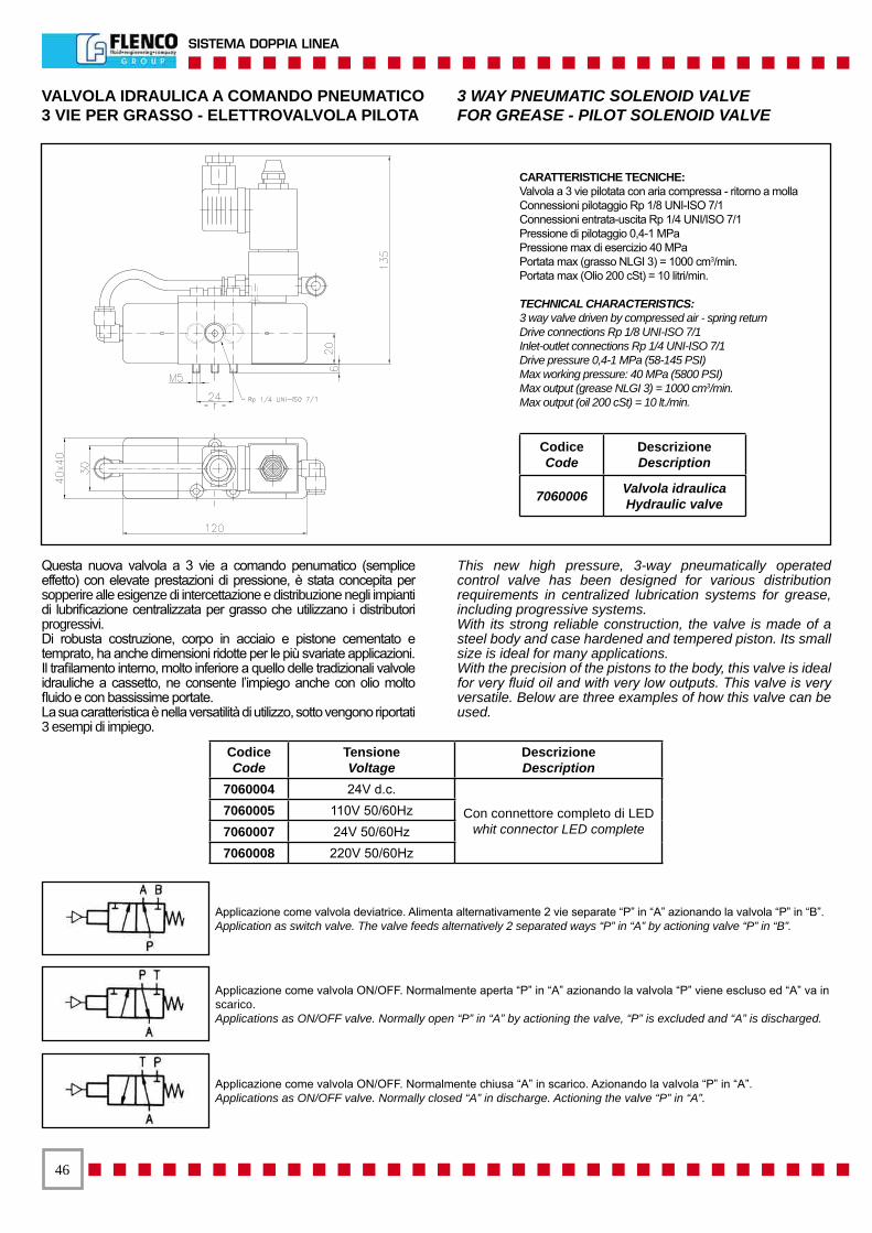
��
SISTEMA DOPPIA LINEA
VALVOLA IDRAULICA A COMANDO PNEUMATICO3 VIE PER GRASSO - ELETTROVALVOLA PILOTA
3 WAY PNEUMATIC SOLENOID VALVEFOR GREASE - PILOT SOLENOID VALVE
Questa nuova valvola a 3 vie a comando penumatico (semplice effetto) con elevate prestazioni di pressione, è stata concepita per sopperire alle esigenze di intercettazione e distribuzione negli impianti di lubrificazione centralizzata per grasso che utilizzano i distributori progressivi.Di robusta costruzione, corpo in acciaio e pistone cementato e temprato, ha anche dimensioni ridotte per le più svariate applicazioni.Il trafilamento interno, molto inferiore a quello delle tradizionali valvole idrauliche a cassetto, ne consente l’impiego anche con olio molto fluido e con bassissime portate.La sua caratteristica è nella versatilità di utilizzo, sotto vengono riportati 3 esempi di impiego.
This new high pressure, 3-way pneumatically operated control valve has been designed for various distribution requirements in centralized lubrication systems for grease, including progressive systems.With its strong reliable construction, the valve is made of a steel body and case hardened and tempered piston. Its small size is ideal for many applications.With the precision of the pistons to the body, this valve is ideal for very fluid oil and with very low outputs. This valve is very versatile. Below are three examples of how this valve can be used.
Applicazione come valvola deviatrice. Alimenta alternativamente 2 vie separate “P” in “A” azionando la valvola “P” in “B”.Application as switch valve. The valve feeds alternatively 2 separated ways “P” in “A” by actioning valve “P” in “B”.
Applicazione come valvola ON/OFF. Normalmente aperta “P” in “A” azionando la valvola “P” viene escluso ed “A” va inscarico.Applications as ON/OFF valve. Normally open “P” in “A” by actioning the valve, “P” is excluded and “A” is discharged.
Applicazione come valvola ON/OFF. Normalmente chiusa “A” in scarico. Azionando la valvola “P” in “A”.Applications as ON/OFF valve. Normally closed “A” in discharge. Actioning the valve “P” in “A”.
CARATTERISTICHE TECNICHE:Valvola a 3 vie pilotata con aria compressa - ritorno a mollaConnessioni pilotaggio Rp 1/8 UNI-ISO 7/1Connessioni entrata-uscita Rp 1/4 UNI/ISO 7/1Pressione di pilotaggio 0,4-1 MPaPressione max di esercizio 40 MPaPortata max (grasso NLGI 3) = 1000 cm3/min.Portata max (Olio 200 cSt) = 10 litri/min.
TECHNICAL CHARACTERISTICS:3 way valve driven by compressed air - spring returnDrive connections Rp 1/8 UNI-ISO 7/1Inlet-outlet connections Rp 1/4 UNI-ISO 7/1Drive pressure 0,4-1 MPa (58-145 PSI)Max working pressure: 40 MPa (5800 PSI)Max output (grease NLGI 3) = 1000 cm3/min.Max output (oil 200 cSt) = 10 lt./min.
CodiceCode
DescrizioneDescription
7060006 Valvola idraulicaHydraulic valve
CodiceCode
TensioneVoltage
DescrizioneDescription
7060004 24V d.c.
Con connettore completo di LEDwhit connector LED complete
7060005 110V 50/60Hz7060007 24V 50/60Hz7060008 220V 50/60Hz
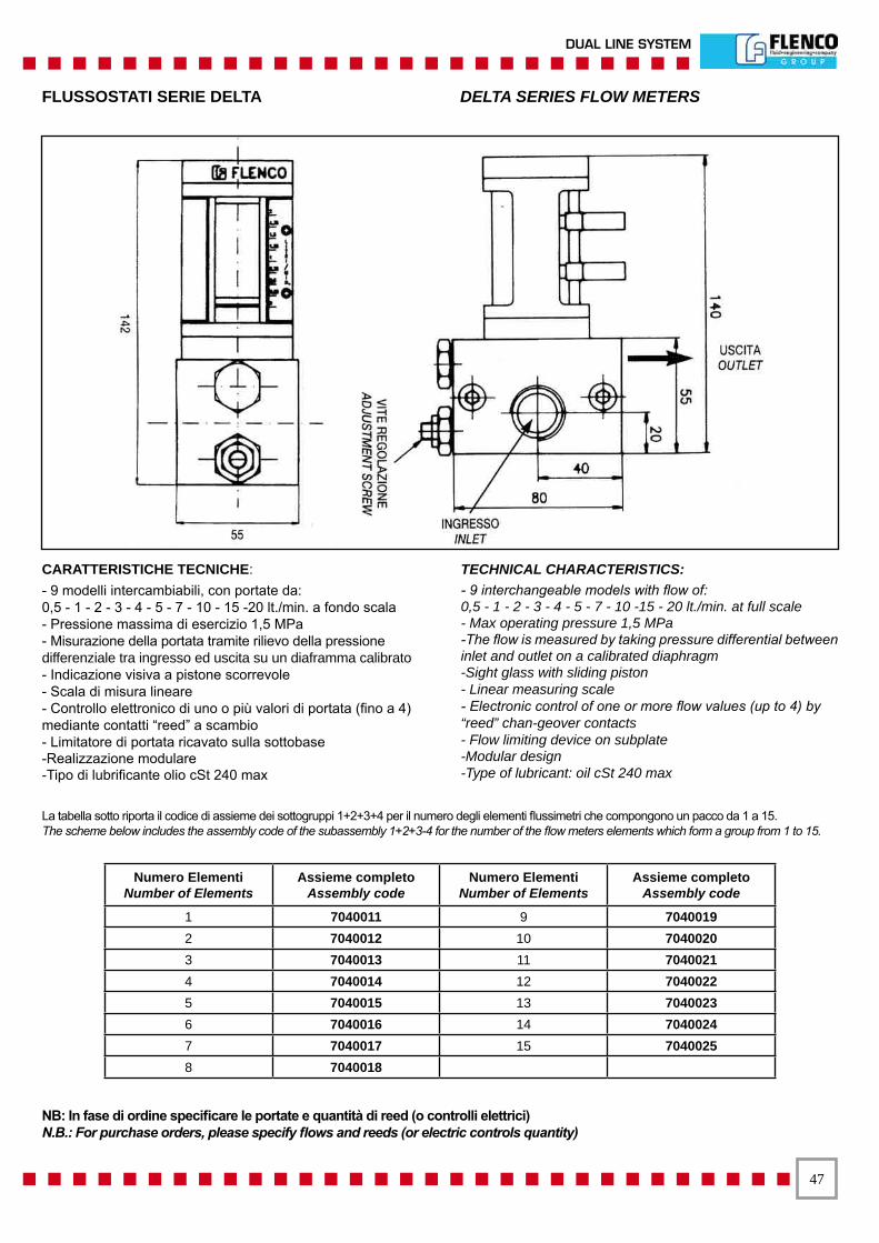
��
DUAL LINE SYSTEM
FLUSSOSTATI SERIE DELTA DELTA SERIES FLOW METERS
La tabella sotto riporta il codice di assieme dei sottogruppi 1+2+3+4 per il numero degli elementi flussimetri che compongono un pacco da 1 a 15.The scheme below includes the assembly code of the subassembly 1+2+3-4 for the number of the flow meters elements which form a group from 1 to 15.
CARATTERISTICHE TECNICHE:- 9 modelli intercambiabili, con portate da:0,5 - 1 - 2 - 3 - 4 - 5 - 7 - 10 - 15 -20 lt./min. a fondo scala- Pressione massima di esercizio 1,5 MPa- Misurazione della portata tramite rilievo della pressione differenziale tra ingresso ed uscita su un diaframma calibrato- Indicazione visiva a pistone scorrevole- Scala di misura lineare- Controllo elettronico di uno o più valori di portata (fino a 4) mediante contatti “reed” a scambio- Limitatore di portata ricavato sulla sottobase-Realizzazione modulare-Tipo di lubrificante olio cSt 240 max
TECHNICAL CHARACTERISTICS:- 9 interchangeable models with flow of:0,5 - 1 - 2 - 3 - 4 - 5 - 7 - 10 -15 - 20 lt./min. at full scale - Max operating pressure 1,5 MPa -The flow is measured by taking pressure differential between inlet and outlet on a calibrated diaphragm-Sight glass with sliding piston- Linear measuring scale- Electronic control of one or more flow values (up to 4) by “reed” chan-geover contacts- Flow limiting device on subplate-Modular design-Type of lubricant: oil cSt 240 max
NB: In fase di ordine specificare le portate e quantità di reed (o controlli elettrici)N.B.: For purchase orders, please specify flows and reeds (or electric controls quantity)
Numero ElementiNumber of Elements
Assieme completoAssembly code
Numero ElementiNumber of Elements
Assieme completoAssembly code
1 7040011 9 70400192 7040012 10 70400203 7040013 11 70400214 7040014 12 70400225 7040015 13 70400236 7040016 14 70400247 7040017 15 70400258 7040018
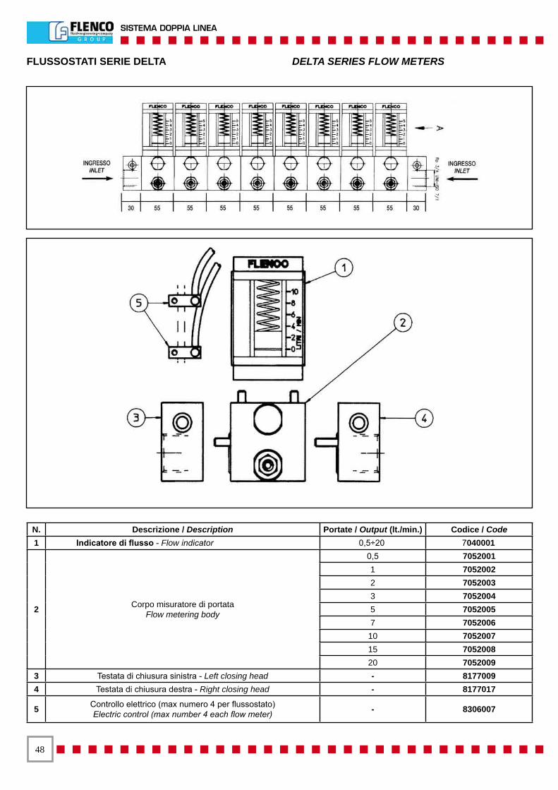
��
SISTEMA DOPPIA LINEA
FLUSSOSTATI SERIE DELTA DELTA SERIES FLOW METERS
N. Descrizione / Description Portate / Output (lt./min.) Codice / Code1 Indicatore di flusso - Flow indicator 0,5÷20 7040001
2 Corpo misuratore di portataFlow metering body
0,5 7052001 1 70520022 7052003 3 7052004 5 70520057 7052006
10 7052007 15 7052008 20 7052009
3 Testata di chiusura sinistra - Left closing head - 81770094 Testata di chiusura destra - Right closing head - 8177017
5 Controllo elettrico (max numero 4 per flussostato)Electric control (max number 4 each flow meter) - 8306007
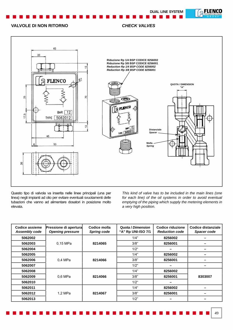
��
DUAL LINE SYSTEM
VALVOLE DI NON RITORNO CHECK VALVES
Questo tipo di valvola va inserita nelle linee principali (una per linea) negli impianti ad olio per evitare eventuali svuotamenti delle tubazioni che vanno ad alimentare dosatori in posizione molto elevata.
This kind of valve has to be included in the main lines (one for each line) of the oil systems in order to avoid eventual emptying of the piping which supply the metering elements in a very high position.
Codice assiemeAssembly code
Pressione di apertura Opening pressure
Codice mollaSpring code
Quota / Dimension“A” Rp UNI-ISO 7/1
Codice riduzioneReduction code
Codice distanzialeSpacer code
5062002 0,15 MPa 8214065
1/4” 8256002 – 5062003 3/8” 8256001 – 5062004 1/2“ – – 5062005
0,4 MPa 8214066 1/4” 8256002 –
5062006 3/8” 8256001 – 5062007 1/2“ – – 5062008
0,6 MPa 8214066 1/4” 8256002
83030075062009 3/8” 8256001 5062010 1/2“ – 5062011
1,2 MPa 8214067 1/4“ 8256002 –
5062012 3/8” 8256001 – 5062013 1/2” – –
Riduzione Rp 1/4 BSP CODICE 8256002Riduzione Rp 3/8 BSP CODICE 8256001Reduction Rp 1/4 BSP CODE 8256002Reduction Rp 3/8 BSP CODE 8256001
DistanzialeSpacer
MollaSpring
QUOTA / DIMENSION“A”
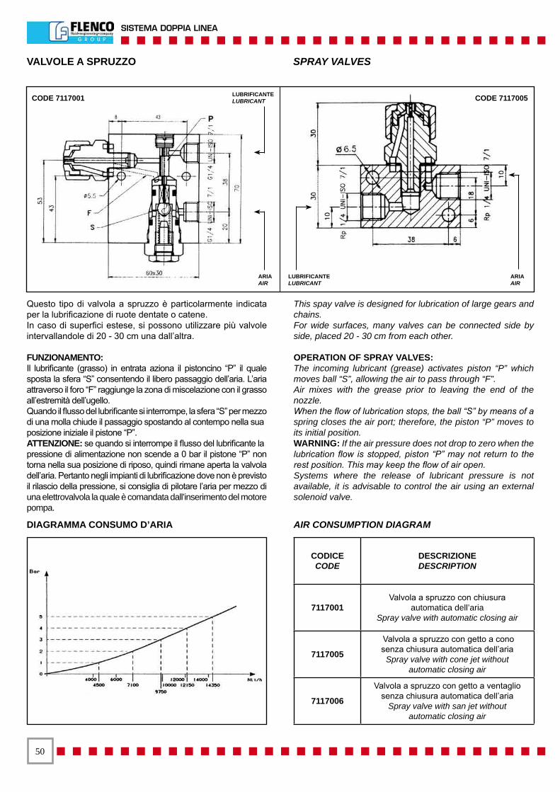
�0
SISTEMA DOPPIA LINEA
VALVOLE A SPRUZZO SPRAY VALVES
Questo tipo di valvola a spruzzo è particolarmente indicata per la lubrificazione di ruote dentate o catene.In caso di superfici estese, si possono utilizzare più valvole intervallandole di 20 - 30 cm una dall’altra.
FUNZIONAMENTO:Il lubrificante (grasso) in entrata aziona il pistoncino “P” il quale sposta la sfera “S” consentendo il libero passaggio dell’aria. L’aria attraverso il foro “F” raggiunge la zona di miscelazione con il grasso all’estremità dell’ugello.Quando il flusso del lubrificante si interrompe, la sfera “S” per mezzo di una molla chiude il passaggio spostando al contempo nella suaposizione iniziale il pistone “P”.ATTENZIONE: se quando si interrompe il flusso del lubrificante lapressione di alimentazione non scende a 0 bar il pistone “P” non torna nella sua posizione di riposo, quindi rimane aperta la valvola dell’aria. Pertanto negli impianti di lubrificazione dove non è previsto il rilascio della pressione, si consiglia di pilotare l’aria per mezzo di una elettrovalvola la quale è comandata dall’inserimento del motore pompa.
This spay valve is designed for lubrication of large gears and chains.For wide surfaces, many valves can be connected side by side, placed 20 - 30 cm from each other.
OPERATION OF SPRAY VALVES:The incoming lubricant (grease) activates piston “P” which moves ball “S”, allowing the air to pass through “F”.Air mixes with the grease prior to leaving the end of the nozzle.When the flow of lubrication stops, the ball “S” by means of a spring closes the air port; therefore, the piston “P” moves to its initial position.WARNING: If the air pressure does not drop to zero when the lubrication flow is stopped, piston “P” may not return to the rest position. This may keep the flow of air open.Systems where the release of lubricant pressure is not available, it is advisable to control the air using an external solenoid valve.
CODICECODE
DESCRIZIONEDESCRIPTION
7117001Valvola a spruzzo con chiusura
automatica dell’ariaSpray valve with automatic closing air
7117005
Valvola a spruzzo con getto a conosenza chiusura automatica dell’aria
Spray valve with cone jet withoutautomatic closing air
7117006
Valvola a spruzzo con getto a ventagliosenza chiusura automatica dell’aria
Spray valve with san jet withoutautomatic closing air
CODE 7117001 CODE 7117005
DIAGRAMMA CONSUMO D’ARIA AIR CONSUMPTION DIAGRAM
LUBRIFICANTELUBRICANT
ARIAAIR
LUBRIFICANTELUBRICANT
ARIAAIR
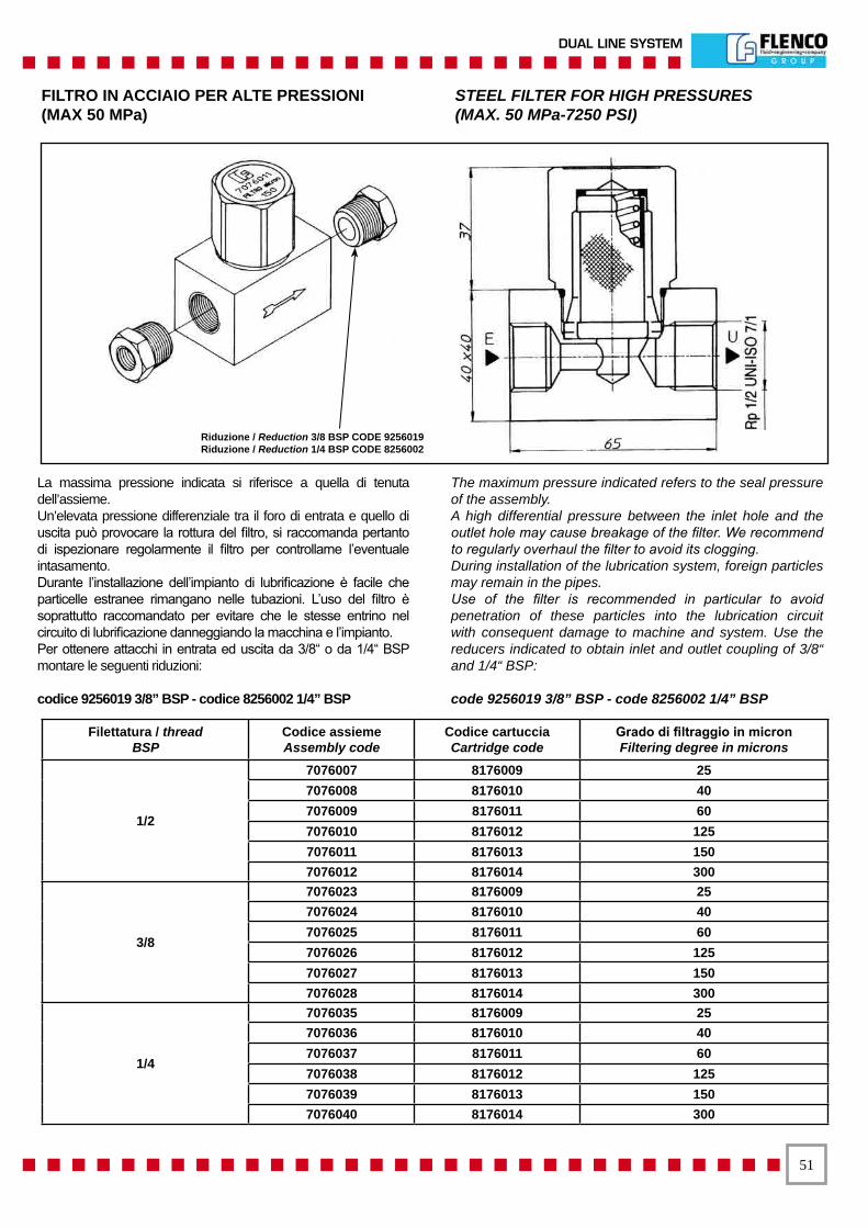
��
DUAL LINE SYSTEM
FILTRO IN ACCIAIO PER ALTE PRESSIONI(MAX 50 MPa)
STEEL FILTER FOR HIGH PRESSURES(MAX. 50 MPa-7250 PSI)
La massima pressione indicata si riferisce a quella di tenuta dell’assieme.Un’elevata pressione differenziale tra il foro di entrata e quello di uscita può provocare la rottura del filtro, si raccomanda pertanto di ispezionare regolarmente il filtro per controllarne l’eventuale intasamento.Durante l’installazione dell’impianto di lubrificazione è facile che particelle estranee rimangano nelle tubazioni. L’uso del filtro è soprattutto raccomandato per evitare che le stesse entrino nel circuito di lubrificazione danneggiando la macchina e l’impianto.Per ottenere attacchi in entrata ed uscita da 3/8“ o da 1/4“ BSP montare le seguenti riduzioni:
codice 9256019 3/8” BSP - codice 8256002 1/4” BSP
The maximum pressure indicated refers to the seal pressure of the assembly.A high differential pressure between the inlet hole and the outlet hole may cause breakage of the filter. We recommend to regularly overhaul the filter to avoid its clogging.During installation of the lubrication system, foreign particles may remain in the pipes.Use of the filter is recommended in particular to avoid penetration of these particles into the lubrication circuit with consequent damage to machine and system. Use the reducers indicated to obtain inlet and outlet coupling of 3/8“ and 1/4“ BSP:
code 9256019 3/8” BSP - code 8256002 1/4” BSP
Filettatura / threadBSP
Codice assiemeAssembly code
Codice cartucciaCartridge code
Grado di filtraggio in micronFiltering degree in microns
1/2
7076007 8176009 25 7076008 8176010 40 7076009 8176011 60 7076010 8176012 125 7076011 8176013 150 7076012 8176014 300
3/8
7076023 8176009 25 7076024 8176010 40 7076025 8176011 60 7076026 8176012 125 7076027 8176013 150 7076028 8176014 300
1/4
7076035 8176009 25 7076036 8176010 40 7076037 8176011 60 7076038 8176012 125 7076039 8176013 150 7076040 8176014 300
Riduzione / Reduction 3/8 BSP CODE 9256019Riduzione / Reduction 1/4 BSP CODE 8256002
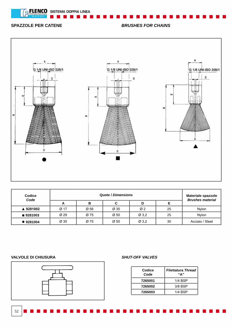
��
SISTEMA DOPPIA LINEA
SPAZZOLE PER CATENE BRUSHES FOR CHAINS
Codice Code
Filettatura Thread “A”
7265001 1/4 BSP 7265002 3/8 BSP 7265003 1/4 BSP
CodiceCode
Quote / Dimensions Materiale spazzoleBrushes material
A B C D E▲ 9281002 Ø 17 Ø 56 Ø 35 Ø 2 25 Nylon
■ 9281003 Ø 29 Ø 75 Ø 50 Ø 3,2 25 Nylon
● 9281004 Ø 30 Ø 75 Ø 50 Ø 3,2 30 Acciaio / Steel
VALVOLE DI CHIUSURA SHUT-OFF VALVES
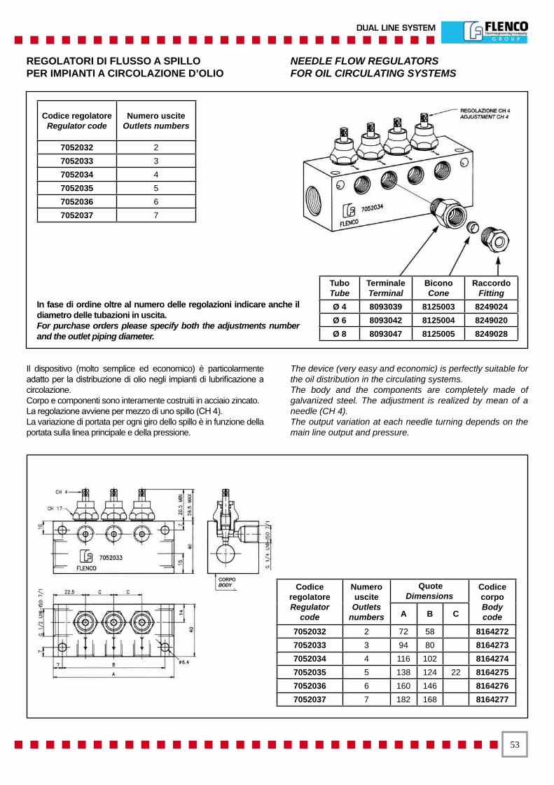
��
DUAL LINE SYSTEM
REGOLATORI DI FLUSSO A SPILLOPER IMPIANTI A CIRCOLAZIONE D’OLIO
NEEDLE FLOW REGULATORSFOR OIL CIRCULATING SYSTEMS
Il dispositivo (molto semplice ed economico) è particolarmente adatto per la distribuzione di olio negli impianti di lubrificazione a circolazione.Corpo e componenti sono interamente costruiti in acciaio zincato.La regolazione avviene per mezzo di uno spillo (CH 4).La variazione di portata per ogni giro dello spillo è in funzione della portata sulla linea principale e della pressione.
The device (very easy and economic) is perfectly suitable for the oil distribution in the circulating systems.The body and the components are completely made of galvanized steel. The adjustment is realized by mean of a needle (CH 4).The output variation at each needle turning depends on the main line output and pressure.
In fase di ordine oltre al numero delle regolazioni indicare anche il diametro delle tubazioni in uscita.For purchase orders please specify both the adjustments number and the outlet piping diameter.
Codice regolatore Regulator code
Numero usciteOutlets numbers
7052032 2 7052033 3 7052034 4 7052035 5 7052036 6 7052037 7
Tubo Tube
Terminale Terminal
Bicono Cone
Raccordo Fitting
Ø 4 8093039 8125003 8249024 Ø 6 8093042 8125004 8249020 Ø 8 8093047 8125005 8249028
CodiceregolatoreRegulator
code
Numero uscite Outlets
numbers
QuoteDimensions
Codice corpo BodycodeA B C
7052032 2 72 58 8164272 7052033 3 94 80 8164273 7052034 4 116 102 8164274 7052035 5 138 124 22 8164275 7052036 6 160 146 8164276 7052037 7 182 168 8164277
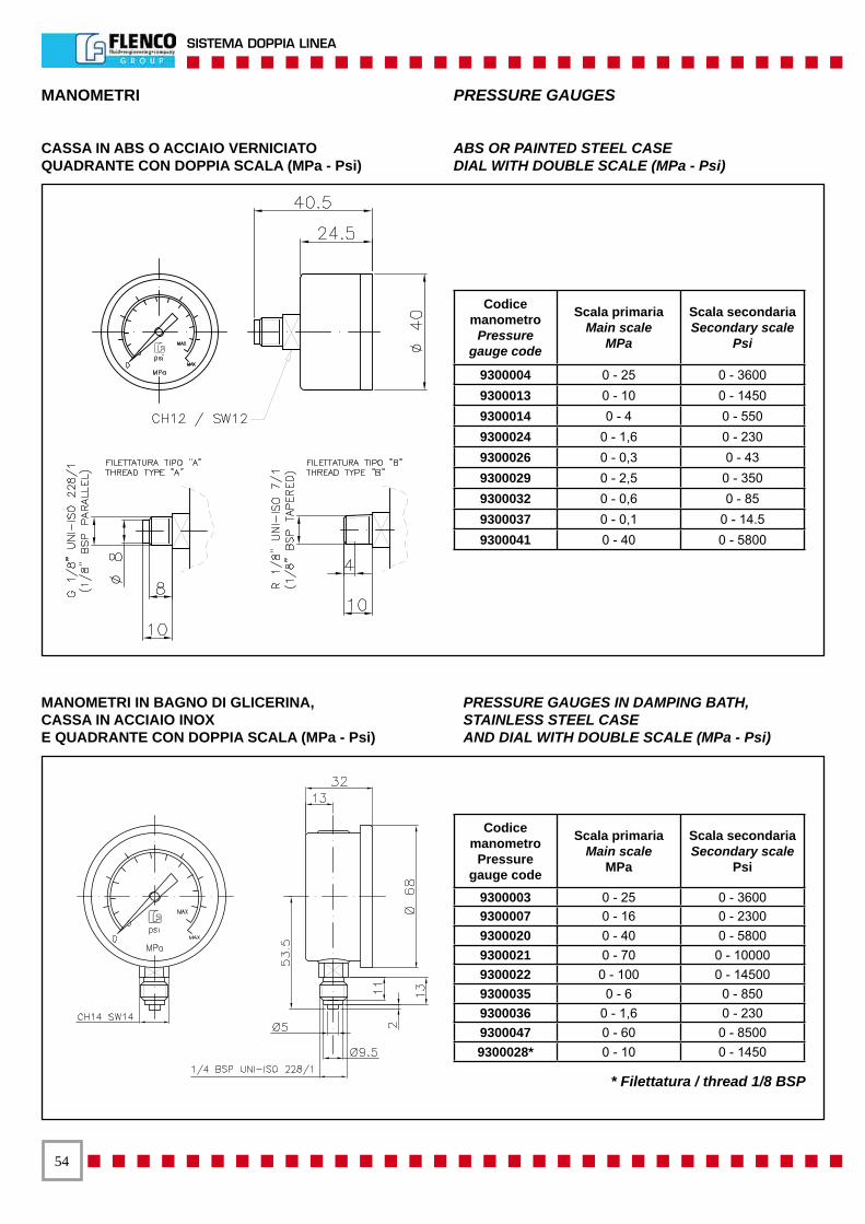
��
SISTEMA DOPPIA LINEA
MANOMETRI PRESSURE GAUGES
CASSA IN ABS O ACCIAIO VERNICIATOQUADRANTE CON DOPPIA SCALA (MPa - Psi)
ABS OR PAINTED STEEL CASEDIAL WITH DOUBLE SCALE (MPa - Psi)
MANOMETRI IN BAGNO DI GLICERINA,CASSA IN ACCIAIO INOX E QUADRANTE CON DOPPIA SCALA (MPa - Psi)
PRESSURE GAUGES IN DAMPING BATH,STAINLESS STEEL CASEAND DIAL WITH DOUBLE SCALE (MPa - Psi)
Codice manometro
Pressuregauge code
Scala primariaMain scale
MPa
Scala secondariaSecondary scale
Psi
9300003 0 - 25 0 - 36009300007 0 - 16 0 - 23009300020 0 - 40 0 - 58009300021 0 - 70 0 - 100009300022 0 - 100 0 - 145009300035 0 - 6 0 - 8509300036 0 - 1,6 0 - 2309300047 0 - 60 0 - 85009300028* 0 - 10 0 - 1450
* Filettatura / thread 1/8 BSP
Codice manometro
Pressuregauge code
Scala primariaMain scale
MPa
Scala secondariaSecondary scale
Psi
9300004 0 - 25 0 - 36009300013 0 - 10 0 - 14509300014 0 - 4 0 - 5509300024 0 - 1,6 0 - 2309300026 0 - 0,3 0 - 439300029 0 - 2,5 0 - 3509300032 0 - 0,6 0 - 859300037 0 - 0,1 0 - 14.59300041 0 - 40 0 - 5800

��
DUAL LINE SYSTEM
Codice Code
FilettaturaThread
TuboTube A B C D E F H
8132019 5/16 - 24NF Ø 4 25 18 18 12,5 5,5 12 Ø 4,5 8132020 1/8 BSP Ø 6 30 20 20 15 4,5 13 Ø 4,5 8132018 1/4 BSP Ø 6 34 30 20 17 8 21 Ø 8,5 8132024 1/4 BSP Ø 8 34 30 20 17 7,5 21 Ø 8,5 8132034 3/8 BSP Ø 10 45 40 30 22,5 7,5 25 Ø 8,5
BLOCCHETTI DI DERIVAZIONE ANCHOR BLOCKS
BLOCCHETTO A CROCE CROSS ANCHOR BLOCK
BLOCCHETTO A “T” 3 - WAY ANCHOR BLOCK
BLOCCHETTO A 90° ATTACCO FRONTALE PER FLEX 90° SINGLE ANCHOR BLOCK FRONT CONNECTION FOR FLEX
BLOCCHETTO A 90° PER FLEX 90° SINGLE ANCHOR BLOCK FOR FLEX
BLOCCHETTO DIRITTO PER FLEX STRAIGHT ANCHOR BLOCK FOR FLEX
CodiceCode
FilettaturaThread
TuboTube A B C D E F H
8132021 5/16 - 24NF Ø 4 20 20 18 9 4,5 14 Ø 4,5 8132022 1/8 BSP Ø 6 25 25 18 9 6 18 Ø 4,5 8132043 1/4 BSP Ø 6 30 30 20 9 7,5 21 Ø 8,5 8132008 1/4 BSP Ø 8 30 30 20 9 7,5 21 Ø 8,5 8132063 3/8 BSP Ø 10 40 40 30 15 7,5 27 Ø 8,5
Codice Code
FilettaturaThread
TuboTube A B C D E F G H
8132030 5/16 - 24NF Ø 4 40 25 18 28,5 9 14,5 16,5 Ø 4,5 8132025 1/8 BSP Ø 6 40 25 18 34 9 19 17 Ø 5,5 8132031 1/4 BSP Ø 6 45 30 20 37 10 20 20 Ø 8,5 8132032 1/4 BSP Ø 8 45 30 20 37 10 20 20 Ø 8,5 8132033 3/8 BSP Ø 10 52 40 30 44 15 25 25 Ø 8,5
Codice Code
FilettaturaThread
BSP
TuboTube A B C D E F H
8132023 1/8 Ø 6 40 25 18 28 6 18 Ø 5,5 8132010 1/4 Ø 6 40 30 20 25 7,5 21 Ø 8,5 8132009 1/4 Ø 8 40 30 20 25 7,5 21 Ø 8,5 8132026 3/8 Ø 10 50 40 25 35 7 27 Ø 8,5
Codice Code
FilettaturaThread
BSP
TuboTube A B C D E F H
8132044 1/8 Ø 6 40 40 18 30 10 20 Ø 4,5 8132017 1/4 Ø 8 40 40 20 25 7,5 20 Ø 5,2
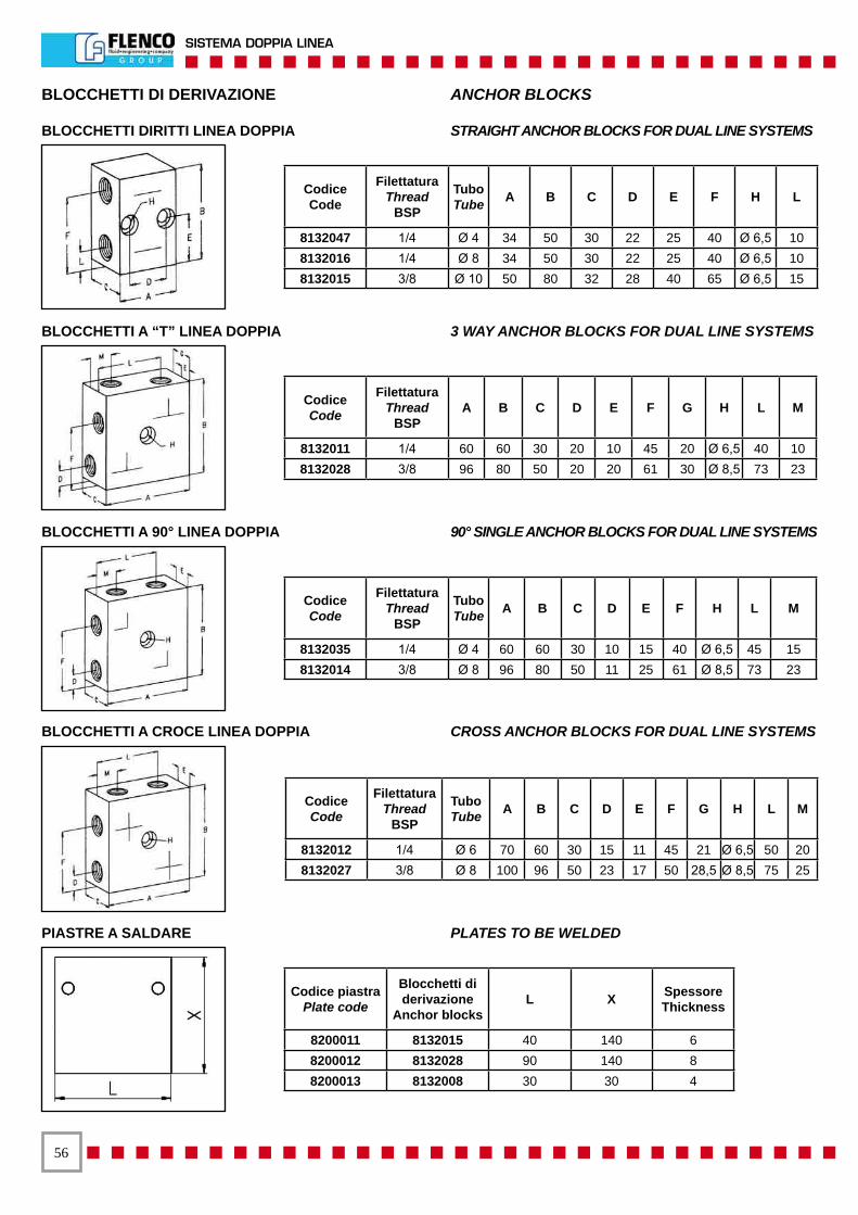
��
SISTEMA DOPPIA LINEA
BLOCCHETTI DI DERIVAZIONE ANCHOR BLOCKS
PIASTRE A SALDARE PLATES TO BE WELDED
BLOCCHETTI A CROCE LINEA DOPPIA CROSS ANCHOR BLOCKS FOR DUAL LINE SYSTEMS
BLOCCHETTI A 90° LINEA DOPPIA 90° SINGLE ANCHOR BLOCKS FOR DUAL LINE SYSTEMS
BLOCCHETTI A “T” LINEA DOPPIA 3 WAY ANCHOR BLOCKS FOR DUAL LINE SYSTEMS
BLOCCHETTI DIRITTI LINEA DOPPIA STRAIGHT ANCHOR BLOCKS FOR DUAL LINE SYSTEMS
CodiceCode
FilettaturaThread
BSP
Tubo Tube A B C D E F H L
8132047 1/4 Ø 4 34 50 30 22 25 40 Ø 6,5 10 8132016 1/4 Ø 8 34 50 30 22 25 40 Ø 6,5 10 8132015 3/8 Ø 10 50 80 32 28 40 65 Ø 6,5 15
CodiceCode
FilettaturaThread
BSPA B C D E F G H L M
8132011 1/4 60 60 30 20 10 45 20 Ø 6,5 40 10 8132028 3/8 96 80 50 20 20 61 30 Ø 8,5 73 23
CodiceCode
FilettaturaThread
BSP
Tubo Tube A B C D E F H L M
8132035 1/4 Ø 4 60 60 30 10 15 40 Ø 6,5 45 15 8132014 3/8 Ø 8 96 80 50 11 25 61 Ø 8,5 73 23
CodiceCode
FilettaturaThread
BSP
Tubo Tube A B C D E F G H L M
8132012 1/4 Ø 6 70 60 30 15 11 45 21 Ø 6,5 50 20 8132027 3/8 Ø 8 100 96 50 23 17 50 28,5 Ø 8,5 75 25
Codice piastraPlate code
Blocchetti di derivazione
Anchor blocks L X Spessore
Thickness
8200011 8132015 40 140 6 8200012 8132028 90 140 8 8200013 8132008 30 30 4
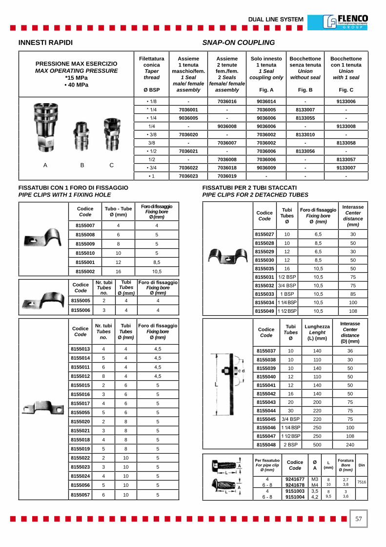
��
DUAL LINE SYSTEM
INNESTI RAPIDI SNAP-ON COUPLING
A B C
CodiceCode
Tubo - TubeØ (mm)
Foro di fissaggioFixing bore
Ø (mm)
8155007 4 4
8155008 6 5
8155009 8 5
8155010 10 5
8155001 12 8,5
8155002 16 10,5
Codice Code
Nr. tubi Tubes
no.
TubiTubesØ (mm)
Foro di fissaggioFixing bore
Ø (mm) 8155005 2 4 4
8155006 3 4 4
Codice Code
Nr. tubi Tubes
no.
TubiTubes
Ø (mm)
Foro di fissaggioFixing bore
Ø (mm)
8155013 4 4 4,5
8155014 5 4 4,5
8155011 6 4 4,5
8155012 8 4 4,5
8155015 2 6 5
8155016 3 6 5
8155017 4 6 5
8155055 5 6 5
8155020 2 8 5
8155021 3 8 5
8155018 4 8 5
8155019 5 8 5
8155022 2 10 5
8155023 3 10 5
8155024 4 10 5
8155056 5 10 5
8155057 6 10 5
Codice Code
TubiTubes
Ø
Lunghezza Lenght
(L) (mm)
InterasseCenter
distance(D) (mm)
8155037 10 140 36
8155038 10 110 30
8155039 10 140 50
8155040 12 110 50
8155041 12 140 50
8155042 16 140 50
8155043 20 200 75
8155044 30 220 75
8155045 3/4 BSP 220 75
8155046 1 1/4 BSP 250 100
8155047 1 1/2 BSP 250 108
8155048 2 BSP 500 240
Per fissatuboFor pipe clip
Ø (mm)
Codice Code
ØA
L(mm)
Foratura Bore
Ø (mm)Din
46 - 8
92416779241678
M3M4
810
2,73,8 7516
46 - 8
91510039151004
3,54,2
89,5
33,6
Codice Code
Tubi Tubes
Ø
Foro di fissaggioFixing bore
Ø (mm)
Interasse Center
distance (mm)
8155027 10 6,5 30
8155028 10 8,5 50
8155029 12 6,5 30
8155030 12 8,5 50
8155035 16 10,5 50
8155031 1/2 BSP 10,5 75
8155032 3/4 BSP 10,5 75
8155033 1 BSP 10,5 85
8155034 1 1/4 BSP 10,5 100
8155049 1 1/2 BSP 10,5 108
PRESSIONE MAX ESERCIZIOMAX OPERATING PRESSURE
*15 MPa• 40 MPa
Filettatura conicaTaperthread
Ø BSP
Assieme1 tenuta
maschio/fem.1 Seal
male/ female assembly
Assieme2 tenute
fem./fem.2 Seals
female/ female assembly
Solo innesto1 tenuta1 Seal
coupling only
Fig. A
Bocchettone senza tenuta
Unionwithout seal
Fig. B
Bocchettonecon 1 tenuta
Unionwith 1 seal
Fig. C
• 1/8 - 7036016 9036014 - 9133006 * 1/4 7036001 - 7036005 8133007 -• 1/4 9036005 - 9036006 8133055 -1/4 - 9036008 9036006 - 9133008
• 3/8 7036020 - 7036002 8133010 -3/8 - 7036007 7036002 - 8133058
• 1/2 7036021 - 7036006 8133056 -1/2 - 7036008 7036006 - 8133057
• 3/4 7036022 7036018 9036009 - 9133007 • 1 7036023 7036019 - - -
FISSATUBI CON 1 FORO DI FISSAGGIOPIPE CLIPS WITH 1 FIXING HOLE
FISSATUBI PER 2 TUBI STACCATIPIPE CLIPS FOR 2 DETACHED TUBES

��
SISTEMA DOPPIA LINEA
TUBI FLESSIBILI FLEXIBLE PIPES
N.B.: Per ordinare un tubo flessibile bisognerà indicare, oltre al numero di codice la lunghezza L in cm. I tubi flessibili in gomma possono essere forniti in rotoli (lunghezza max. 15 m) con i raccordi staccati, perl’assiemaggio nella misura voluta a carico del cliente. Quelli con corazza esterna in acciaio devono essere ordinati sempre completi.
Note: To order a flexible tube, in addition to the code, the length L in cm must be specified. Rubber flexible tubes can be supplied in coils (max. length 15 m.) with the fittings loose, for assembly in the desired length, on the client’s premises.Those with external steel armour must always be ordered complete.
Assieme flex con corazza
esterna in acciaio codice
Hose assembly with external
steel armour code
Assieme flex in gomma antiolio
codice Hose assembly
in oil - proofrubber code
Solo tubo in gomma
codice Rubber tube
only code(C)
Bocchettonecodice
Union code(D)
Ø Tubo
ØA
mm
ØB
mm
Raggio minimo
di curvatura Min. bending
radius
Pressione esercizio Working pressure
Est. Int.
Ø Tube
O.D. I.D. mm. MPa PSI
9107046 9107052 3304002 8133004 13 4 4 20 35 10 1450 9107009 9107018 3304002 8133003 13 4 6 25 35 10 1450 9107035 9107053 3304003 8133021 17 6 6 24 50 15 2175 9107014 9107031 3304012 8133066 19 8 8 25 60 15 2175 9107015 9107054 3304013 8133067 19 8 10 25 60 40 5800 9107049 9107055 3304014 8133068 21 10 12 25 65 40 5800 9107050 9107056 3304015 8133069 24 13 16 30 70 35 5075 9107051 9107057 3304016 8133070 28 16 20 32 80 30 4350
Assieme flexcon corazza
esterna in acciaiocodice
Hose assemblywith externalsteel armour
code
Assieme flexin gomma antiolio
codice
Hose assemblyin oil - proofrubber code
Solo tubo in gomma
codice
Rubber tube only code
(C)
Raccordomaschio girevolecodice
Male fittingswivel code
(D)
Raccordomaschio
fissocodice
Male fittingsolid code
(E)
TuboTube
Ø (mm.)
Filettaturacilindrica
Cylinidricthread
Ø A BSP
Raggio minimodi curvatura
Minimum bendingradius
(mm.)
PressioneesercizioWorkingpressure
MPa PSIEst.O.D.
Int.I.D.
9107030 9107058 3304002 9133011 9133011 13 4 1/8 35 10 14509107012 9107059 3304002 9133012 9133012 13 4 1/4 35 10 14509107034 9107024 3304006 8133025 8133032 16,5 6 1/4 50 4 5809107006 9107019 3304001 8133026 8133033 17 8 1/4 90 10 14509107020 9107008 3304017 8133027 8133034 17,5 8 1/4 105 20 29009107021 9107007 3304007 8133028 8133035 19,5 9,5 3/8 125 20 29009107022 9107036 3304008 8133029 8133036 23 13 3/8 180 20 29009107033 9107037 3304013 8133030 8133037 19 8 1/4 60 40 58009107032 9107038 3304014 8133031 8133038 21 10 3/8 65 40 5800
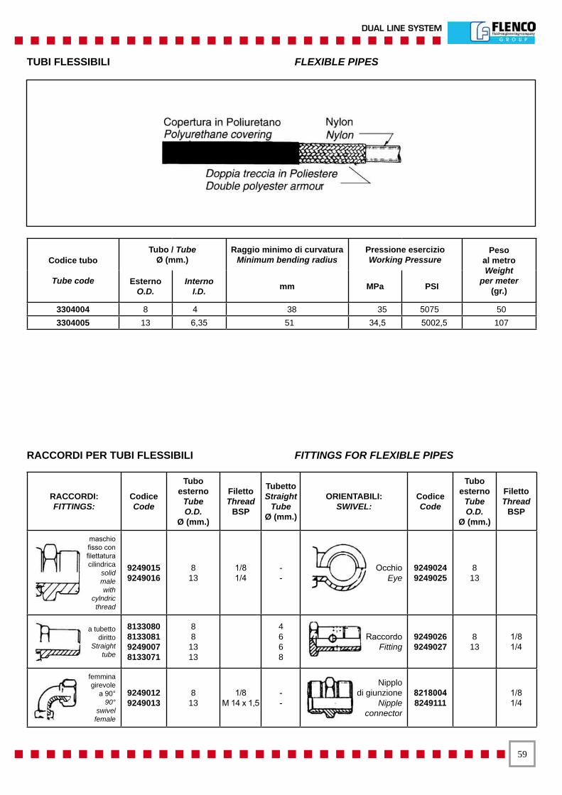
��
DUAL LINE SYSTEM
RACCORDI:FITTINGS:
CodiceCode
Tubo esterno
TubeO.D.
Ø (mm.)
Filetto Thread
BSP
Tubetto Straight
TubeØ (mm.)
ORIENTABILI:SWIVEL:
CodiceCode
Tubo esterno
TubeO.D.
Ø (mm.)
Filetto Thread
BSP
maschio fisso con filettaturacilindrica
solidmale with
cylndric thread
9249015 9249016
813
1/81/4
--
OcchioEye
9249024 9249025
813
a tubettodiritto
Straighttube
8133080 8133081 9249007 8133071
88
1313
4668
RaccordoFitting
9249026 9249027
813
1/81/4
femminagirevole
a 90°90°
swivelfemale
9249012 9249013
813
1/8M 14 x 1,5
--
Nipplodi giunzione
Nippleconnector
8218004 8249111
1/81/4
TUBI FLESSIBILI FLEXIBLE PIPES
Codice tubo
Tube code
Tubo / TubeØ (mm.)
Raggio minimo di curvaturaMinimum bending radius
Pressione esercizioWorking Pressure
Pesoal metroWeight
per meter(gr.)
EsternoO.D.
InternoI.D. mm MPa PSI
3304004 8 4 38 35 5075 50 3304005 13 6,35 51 34,5 5002,5 107
RACCORDI PER TUBI FLESSIBILI FITTINGS FOR FLEXIBLE PIPES

�0
SISTEMA DOPPIA LINEA
RACCORDERIA PER DOPPIO CONOPRESSIONE MAX. 15 MPa
COMPRESSION FITTINGSMAX PRESSURE 15 MPa (2175 PSI)
TuboTube
Ø(mm)
FilettatureThreads
Terminalecompleto
senza valvola
CompleteFittingwithout
check valve
Terminalecompleto
con valvola
CompleteFittingwith
check valve
● Filettature
Threads
● Terminalesenza valvola
Fittingwithout
check valve
● Terminalecon valvola
Fittingwith
check valve
● Raccordo
Fitting
Doppiocono
Doublecone
metric BSP Code H Code H CH CH1 metric BSP Code H1 Code H1
4 M6x0,75 7093030 10 9 5/16-24NF 8093059 17 8249024 8125003
4 M6x1 7093031 10 9 5-16-24NF 8093062 17 8249024 8125003
4 M8x1,25▲ 7093001 7097001 30,5 10 9 5/16-24NF 8093036 17,5 8097001 24 8249024 8125003
4 1/8 7093003 1/8 7097002 30,5 10 9 5-16-24NF 8093038 17,5 8097002 24 8249024 8125003
4 M10x1 7093002 11 9 M8x1 8093037 17,5 8249022 8125003
4 1/4 7093004 1/4 14 9 5/16-24NF 8093039 24 8249024 8125003
6 M10x1 7093005 12 10 M10x1 8093040 23 8249026 8125004
6 M12x1 1/8 8256007 20 8125004
6 1/8 7093006 1/8 1/8 8164077 27 8249027 8125004
6 1/8 1/8 7097003 36 17 14 1/4 8097003 27 8249020 8125004
6 1/4 7093007 1/4 7097004 38 17 14 1/4 8093042 25 8097004 29 8249020 8125004
6 1/4 7093008 1/4 17 10 1/8 8093043 23 8249027 8125004
6 3/8 7093009 3/8 19 14 1/4 8093044 24 8249020 8125004
6 1/2 7093010 1/2 22 14 1/4 8093003 27 8249020 8125004
8 1/8 7093011 1/8 7097005 37 17 14 1/4 8093046 24 8097005 27 8249028 8125005
8 1/4 7093012 1/4 7097006 39 17 14 1/4 8093047 25 8097006 29 8249028 8125005
8 3/8 7093013 3/8 19 14 1/4 8093009 24 8249028 8125005
8 1/2 7093014 1/2 22 14 1/4 8093049 27 8249028 8125005
10 1/4 7093015 1/4 22 17 3/8 8093050 30 8249021 8125006
10 3/8 7093016 3/8 7097007 43 22 17 3/8 8093051 30 8097007 30.5 8249021 8125006
10 1/2 7093017 1/2 22 17 3/8 8093006 29 8249021 8125006
6 1/4 7093018 1/4 17 14 1/4 8093053 25 8249021 8125004
6 ▲ 7093019 19 14 1/4 8093054 27,5 8249020 8125004
8 3/8 7093020 3/8 17 14 1/4 8093055 25 8249028 8125005
8 ▲ 7093021 19 14 1/4 8093056 27,5 8249028 8125005
10 1/4 7093022 1/4 22 17 3/8 8093057 32 8249021 8125006
10 ▲ 7093023 22 17 3/8 8093058 30 8249021 8125006
▲ Filettatura cilindrica ▲ Cylindrical thread
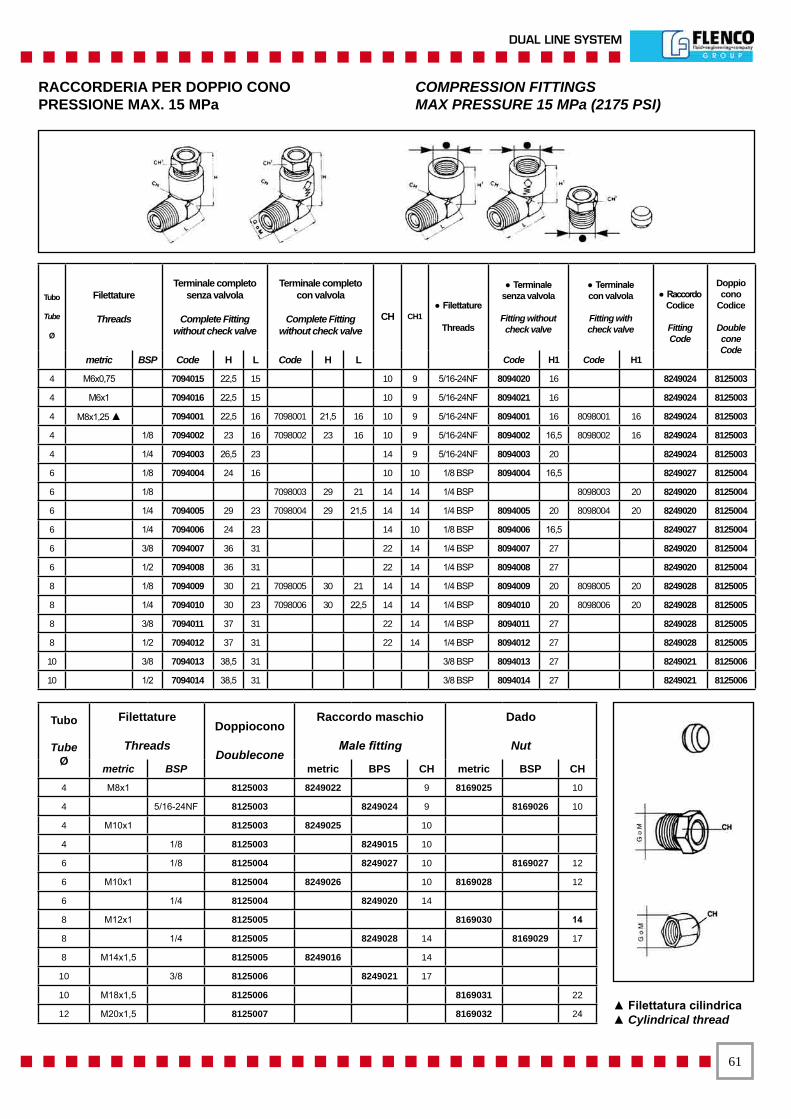
��
DUAL LINE SYSTEM
RACCORDERIA PER DOPPIO CONOPRESSIONE MAX. 15 MPa
COMPRESSION FITTINGSMAX PRESSURE 15 MPa (2175 PSI)
Tubo
Tube
Ø
Filettature
Threads
Terminale completosenza valvola
Complete Fittingwithout check valve
Terminale completocon valvola
Complete Fittingwithout check valve
CH CH1● Filettature
Threads
● Terminale senza valvola
Fitting without check valve
● Terminalecon valvola
Fitting withcheck valve
● RaccordoCodice
FittingCode
Doppiocono
Codice
DoubleconeCode
metric BSP Code H L Code H L Code H1 Code H1
4 M6x0,75 7094015 22,5 15 10 9 5/16-24NF 8094020 16 8249024 8125003
4 M6x1 7094016 22,5 15 10 9 5/16-24NF 8094021 16 8249024 8125003
4 M8x1,25 ▲ 7094001 22,5 16 7098001 21,5 16 10 9 5/16-24NF 8094001 16 8098001 16 8249024 8125003
4 1/8 7094002 23 16 7098002 23 16 10 9 5/16-24NF 8094002 16,5 8098002 16 8249024 8125003
4 1/4 7094003 26,5 23 14 9 5/16-24NF 8094003 20 8249024 8125003
6 1/8 7094004 24 16 10 10 1/8 BSP 8094004 16,5 8249027 8125004
6 1/8 7098003 29 21 14 14 1/4 BSP 8098003 20 8249020 8125004
6 1/4 7094005 29 23 7098004 29 21,5 14 14 1/4 BSP 8094005 20 8098004 20 8249020 8125004
6 1/4 7094006 24 23 14 10 1/8 BSP 8094006 16,5 8249027 8125004
6 3/8 7094007 36 31 22 14 1/4 BSP 8094007 27 8249020 8125004
6 1/2 7094008 36 31 22 14 1/4 BSP 8094008 27 8249020 8125004
8 1/8 7094009 30 21 7098005 30 21 14 14 1/4 BSP 8094009 20 8098005 20 8249028 8125005
8 1/4 7094010 30 23 7098006 30 22,5 14 14 1/4 BSP 8094010 20 8098006 20 8249028 8125005
8 3/8 7094011 37 31 22 14 1/4 BSP 8094011 27 8249028 8125005
8 1/2 7094012 37 31 22 14 1/4 BSP 8094012 27 8249028 8125005
10 3/8 7094013 38,5 31 3/8 BSP 8094013 27 8249021 8125006
10 1/2 7094014 38,5 31 3/8 BSP 8094014 27 8249021 8125006
▲ Filettatura cilindrica▲ Cylindrical thread
Tubo
TubeØ
Filettature
ThreadsDoppiocono
Doublecone
Raccordo maschio
Male fitting
Dado
Nut
metric BSP metric BPS CH metric BSP CH4 M8x1 8125003 8249022 9 8169025 10
4 5/16-24NF 8125003 8249024 9 8169026 10
4 M10x1 8125003 8249025 10
4 1/8 8125003 8249015 10
6 1/8 8125004 8249027 10 8169027 12
6 M10x1 8125004 8249026 10 8169028 12
6 1/4 8125004 8249020 14
8 M12x1 8125005 8169030 14
8 1/4 8125005 8249028 14 8169029 17
8 M14x1,5 8125005 8249016 14
10 3/8 8125006 8249021 17
10 M18x1,5 8125006 8169031 22
12 M20x1,5 8125007 8169032 24
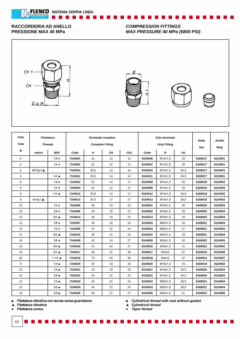
��
SISTEMA DOPPIA LINEA
RACCORDERIA AD ANELLOPRESSIONE MAX 40 MPa
COMPRESSION FITTINGSMAX PRESSURE 40 MPa (5800 PSI)
Tubo
Tube
Ø
Filettatura
Threads
Terminale completo
Complete Fitting
Solo terminale
Only FittingDado
Nut
Anello
Ring
metric BSP Code H CH CH1 Code B H1
6 1/8 ● 7104001 31 14 14 8104006 M12x1,5 25 8169017 8124001
6 1/4 ● 7104002 31 14 14 8104007 M12x1,5 25 8169017 8124001
6 M12x1▲ 7104010 30,5 14 14 8104010 M12x1,5 24,5 8169017 8124001
6 1/4 ▲ 7104011 30,5 14 14 8104011 M12x1,5 24,5 8169017 8124001
8 1/8 ● 7104003 31 14 17 8104008 M14x1,5 25 8169018 8124002
8 1/4 ● 7104004 31 14 17 8104009 M14x1,5 25 8169018 8124002
8 1/4 ▲ 7104012 30,5 14 17 8104012 M14x1,5 24,5 8169018 8124002
8 M16x1▲ 7104013 34,5 17 17 8104013 M14x1,5 26,5 8169018 8124002
10 1/4 ● 7104005 39 19 22 8104001 M18x1,5 30 8169020 8124003
10 3/8 ● 7104006 39 19 22 8104002 M18x1,5 30 8169020 8124003
10 3/8 ▲ 7104014 38 19 22 8104014 M18x1,5 29 8169020 8124003
12 3/8 ● 7104007 40 22 24 8104003 M20x1,5 30 8169021 8124004
12 1/2 ● 7104008 47 22 24 8104004 M20x1,5 37 8169021 8124004
12 3/8 ▲ 7104015 39 22 24 8104015 M20x1,5 29 8169021 8124004
16 3/8 ● 7104009 42 24 27 8104005 M24x1,5 32 8169022 8124005
16 3/8 ▲ 7104016 41 24 27 8104016 M24x1,5 31 8169022 8124005
20 3/4 ▲ 7104017 58 32 36 8104017 M30x2 47 8169023 8124006
30 1 1/4 ▲ 7104018 70 50 50 8104018 M42x2 57 8169024 8124007
8 1/4 ■ 7104020 42 19 19 8104020 M16x1,5 34 8169019 8124002
10 1/4 ■ 7104021 43 19 22 8104021 M18x1,5 34,5 8169020 8124003
10 3/8 ■ 7104022 43 22 22 8104022 M18x1,5 34,5 8169020 8124003
12 1/4 ■ 7104023 45 22 24 8104023 M20x1,5 36,5 8169021 8124004
12 3/8 ■ 7104024 45 22 24 8104024 M20x1,5 36,5 8169021 8124004
16 3/8 ■ 7104025 49 27 27 8104025 M24x1,5 41 8169022 8124005
■ Filettatura cilindrica con tenuta senza guarnizione▲ Filettatura cilindrica● Filettatura conica
■ Cylindrical thread with seal without gasket▲ Cylindrical thread● Taper thread
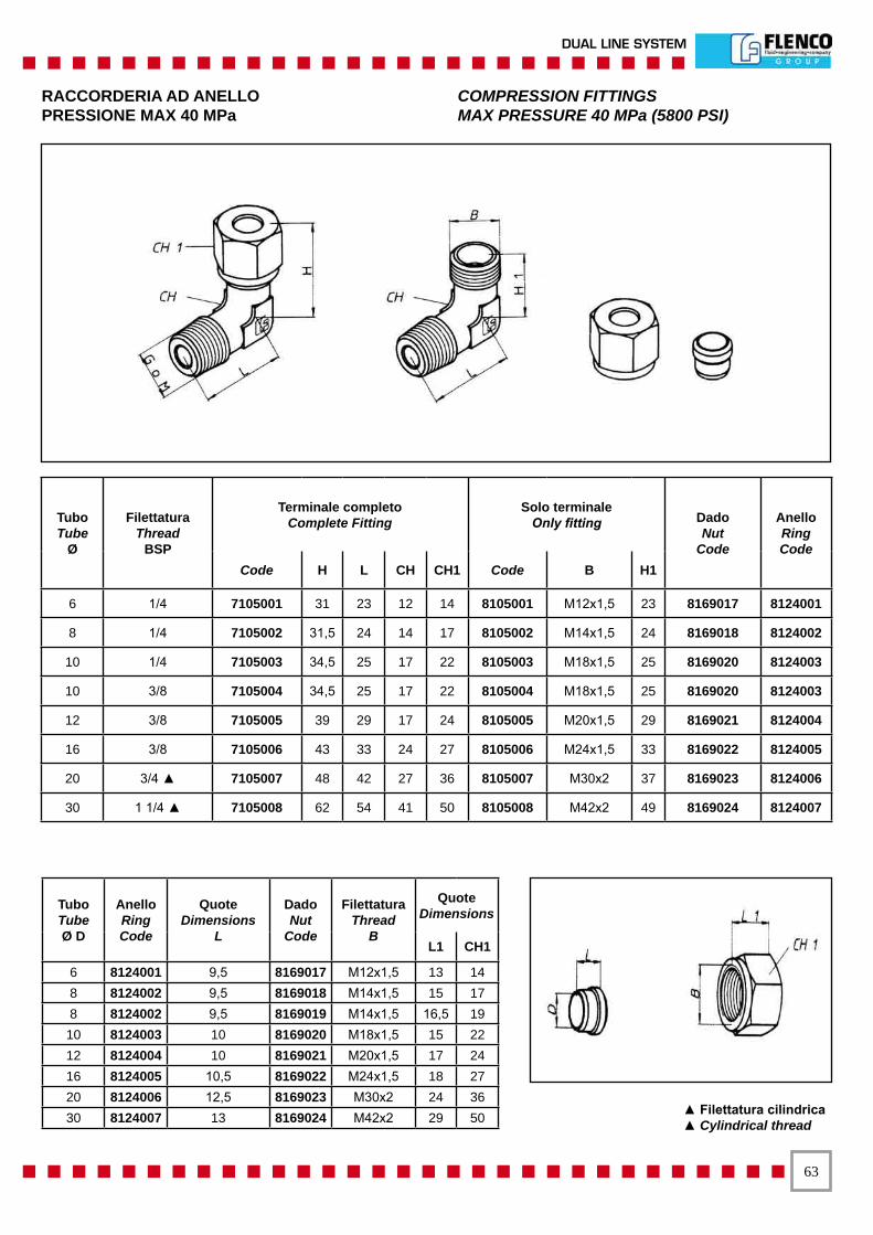
��
DUAL LINE SYSTEM
RACCORDERIA AD ANELLOPRESSIONE MAX 40 MPa
COMPRESSION FITTINGSMAX PRESSURE 40 MPa (5800 PSI)
Tubo Tube
Ø
FilettaturaThread
BSP
Terminale completoComplete Fitting
Solo terminaleOnly fitting Dado
NutCode
Anello RingCode
Code H L CH CH1 Code B H1
6 1/4 7105001 31 23 12 14 8105001 M12x1,5 23 8169017 8124001
8 1/4 7105002 31,5 24 14 17 8105002 M14x1,5 24 8169018 8124002
10 1/4 7105003 34,5 25 17 22 8105003 M18x1,5 25 8169020 8124003
10 3/8 7105004 34,5 25 17 22 8105004 M18x1,5 25 8169020 8124003
12 3/8 7105005 39 29 17 24 8105005 M20x1,5 29 8169021 8124004
16 3/8 7105006 43 33 24 27 8105006 M24x1,5 33 8169022 8124005
20 3/4 ▲ 7105007 48 42 27 36 8105007 M30x2 37 8169023 8124006
30 1 1/4 ▲ 7105008 62 54 41 50 8105008 M42x2 49 8169024 8124007
Tubo TubeØ D
Anello RingCode
QuoteDimensions
L
Dado Nut
Code
Filettatura Thread
B
Quote Dimensions
L1 CH1
6 8124001 9,5 8169017 M12x1,5 13 14 8 8124002 9,5 8169018 M14x1,5 15 17 8 8124002 9,5 8169019 M14x1,5 16,5 19
10 8124003 10 8169020 M18x1,5 15 22 12 8124004 10 8169021 M20x1,5 17 24 16 8124005 10,5 8169022 M24x1,5 18 27 20 8124006 12,5 8169023 M30x2 24 36 30 8124007 13 8169024 M42x2 29 50 ▲ Filettatura cilindrica
▲ Cylindrical thread
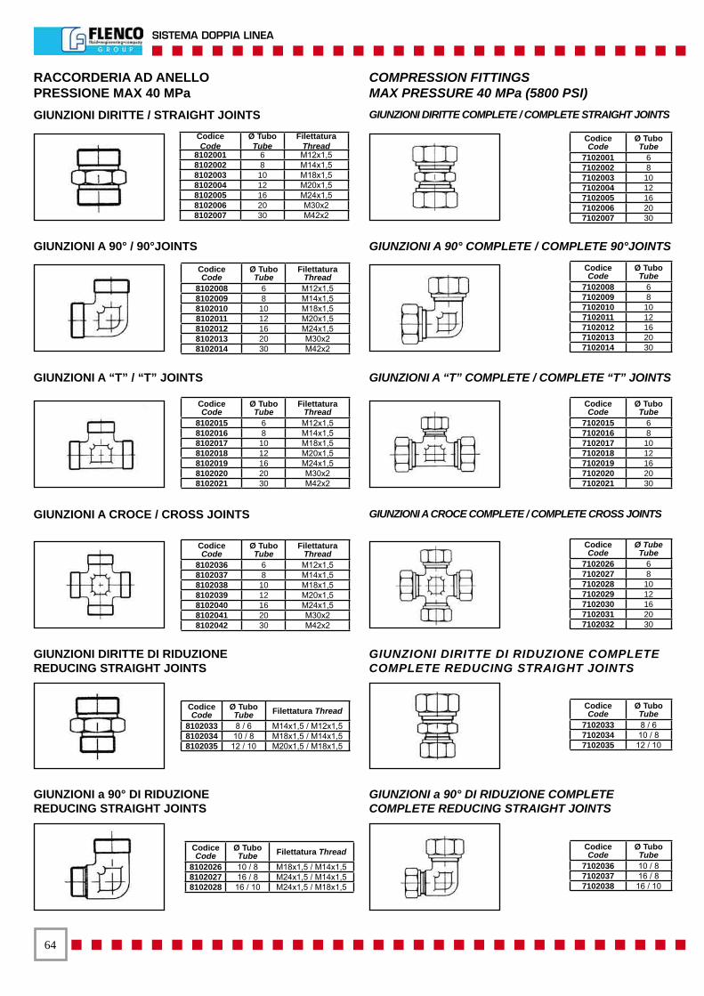
��
SISTEMA DOPPIA LINEA
CodiceCode
Ø TuboTube
Filettatura Thread
8102008 6 M12x1,5 8102009 8 M14x1,5 8102010 10 M18x1,5 8102011 12 M20x1,5 8102012 16 M24x1,5 8102013 20 M30x2 8102014 30 M42x2
Codice Code
Ø TuboTube
7102001 6 7102002 8 7102003 10 7102004 12 7102005 16 7102006 20 7102007 30
CodiceCode
Ø TuboTube
Filettatura Thread
8102015 6 M12x1,5 8102016 8 M14x1,5 8102017 10 M18x1,5 8102018 12 M20x1,5 8102019 16 M24x1,5 8102020 20 M30x2 8102021 30 M42x2
CodiceCode
Ø TuboTube
Filettatura Thread
8102036 6 M12x1,5 8102037 8 M14x1,5 8102038 10 M18x1,5 8102039 12 M20x1,5 8102040 16 M24x1,5 8102041 20 M30x2 8102042 30 M42x2
CodiceCode
Ø TuboTube Filettatura Thread
8102033 8 / 6 M14x1,5 / M12x1,5 8102034 10 / 8 M18x1,5 / M14x1,5 8102035 12 / 10 M20x1,5 / M18x1,5
Codice Code
Ø TuboTube
7102008 6 7102009 8 7102010 10 7102011 12 7102012 16 7102013 20 7102014 30
Codice Code
Ø TuboTube
7102015 6 7102016 8 7102017 10 7102018 12 7102019 16 7102020 20 7102021 30
Codice Code
Ø TubeTube
7102026 6 7102027 8 7102028 10 7102029 12 7102030 16 7102031 20 7102032 30
Codice Code
Ø TuboTube
7102033 8 / 6 7102034 10 / 8 7102035 12 / 10
Codice Code
Ø TuboTube
7102036 10 / 8 7102037 16 / 8 7102038 16 / 10
RACCORDERIA AD ANELLOPRESSIONE MAX 40 MPa
COMPRESSION FITTINGSMAX PRESSURE 40 MPa (5800 PSI)
CodiceCode
Ø TuboTube
FilettaturaThread
8102001 6 M12x1,58102002 8 M14x1,58102003 10 M18x1,58102004 12 M20x1,58102005 16 M24x1,58102006 20 M30x28102007 30 M42x2
CodiceCode
Ø TuboTube Filettatura Thread
8102026 10 / 8 M18x1,5 / M14x1,58102027 16 / 8 M24x1,5 / M14x1,58102028 16 / 10 M24x1,5 / M18x1,5
GIUNZIONI A 90° / 90°JOINTS GIUNZIONI A 90° COMPLETE / COMPLETE 90°JOINTS
GIUNZIONI A “T” / “T” JOINTS GIUNZIONI A “T” COMPLETE / COMPLETE “T” JOINTS
GIUNZIONI A CROCE / CROSS JOINTS GIUNZIONI A CROCE COMPLETE / COMPLETE CROSS JOINTS
GIUNZIONI DIRITTE DI RIDUZIONEREDUCING STRAIGHT JOINTS
GIUNZIONI DIRITTE DI RIDUZIONE COMPLETECOMPLETE REDUCING STRAIGHT JOINTS
GIUNZIONI a 90° DI RIDUZIONEREDUCING STRAIGHT JOINTS
GIUNZIONI a 90° DI RIDUZIONE COMPLETECOMPLETE REDUCING STRAIGHT JOINTS
GIUNZIONI DIRITTE / STRAIGHT JOINTS GIUNZIONI DIRITTE COMPLETE / COMPLETE STRAIGHT JOINTS
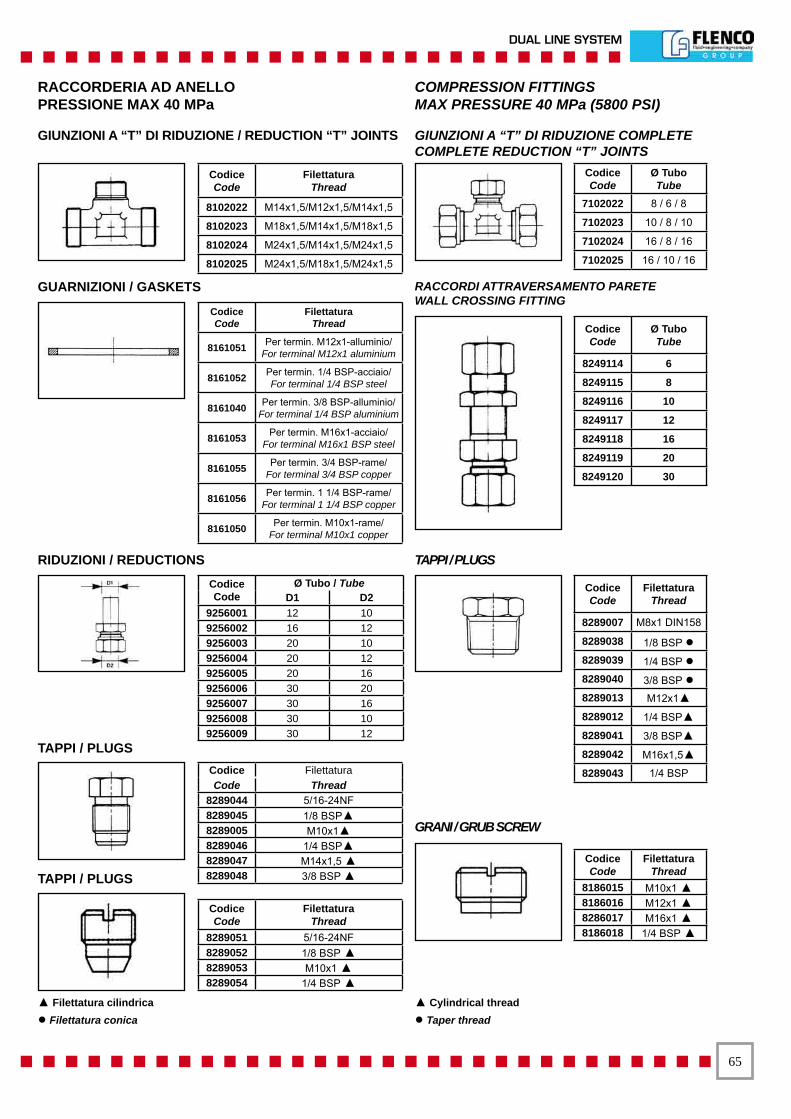
��
DUAL LINE SYSTEM
GUARNIZIONI / GASKETS RACCORDI ATTRAVERSAMENTO PARETE WALL CROSSING FITTING
TAPPI / PLUGS
GRANI / GRUB SCREW
RACCORDERIA AD ANELLOPRESSIONE MAX 40 MPa
COMPRESSION FITTINGSMAX PRESSURE 40 MPa (5800 PSI)
RIDUZIONI / REDUCTIONS
GIUNZIONI A “T” DI RIDUZIONE / REDUCTION “T” JOINTS GIUNZIONI A “T” DI RIDUZIONE COMPLETECOMPLETE REDUCTION “T” JOINTS
Codice Code
Ø TuboTube
7102022 8 / 6 / 8
7102023 10 / 8 / 10
7102024 16 / 8 / 16
7102025 16 / 10 / 16
Codice Code
FilettaturaThread
8161051 Per termin. M12x1-alluminio/For terminal M12x1 aluminium
8161052 Per termin. 1/4 BSP-acciaio/For terminal 1/4 BSP steel
8161040 Per termin. 3/8 BSP-alluminio/For terminal 1/4 BSP aluminium
8161053 Per termin. M16x1-acciaio/For terminal M16x1 BSP steel
8161055 Per termin. 3/4 BSP-rame/For terminal 3/4 BSP copper
8161056 Per termin. 1 1/4 BSP-rame/For terminal 1 1/4 BSP copper
8161050 Per termin. M10x1-rame/For terminal M10x1 copper
Codice Code
Ø Tubo / TubeD1 D2
9256001 12 10 9256002 16 12 9256003 20 10 9256004 20 12 9256005 20 16 9256006 30 20 9256007 30 16 9256008 30 10 9256009 30 12
Codice Filettatura Code Thread
8289044 5/16-24NF 8289045 1/8 BSP▲8289005 M10x1▲8289046 1/4 BSP▲8289047 M14x1,5 ▲8289048 3/8 BSP ▲
Codice Code
Filettatura Thread
8289051 5/16-24NF 8289052 1/8 BSP ▲8289053 M10x1 ▲8289054 1/4 BSP ▲
Codice Code
Ø TuboTube
8249114 6
8249115 8
8249116 10
8249117 12
8249118 16
8249119 20
8249120 30
Codice Code
Filettatura Thread
8186015 M10x1 ▲8186016 M12x1 ▲8286017 M16x1 ▲8186018 1/4 BSP ▲
Codice Code
Filettatura Thread
8102022 M14x1,5/M12x1,5/M14x1,5
8102023 M18x1,5/M14x1,5/M18x1,5
8102024 M24x1,5/M14x1,5/M24x1,5
8102025 M24x1,5/M18x1,5/M24x1,5
Codice Code
Filettatura Thread
8289007 M8x1 DIN158
8289038 1/8 BSP ●8289039 1/4 BSP ●8289040 3/8 BSP ●8289013 M12x1▲8289012 1/4 BSP▲8289041 3/8 BSP▲8289042 M16x1,5▲8289043 1/4 BSP
TAPPI / PLUGS
▲ Filettatura cilindrica● Filettatura conica
▲ Cylindrical thread● Taper thread
TAPPI / PLUGS
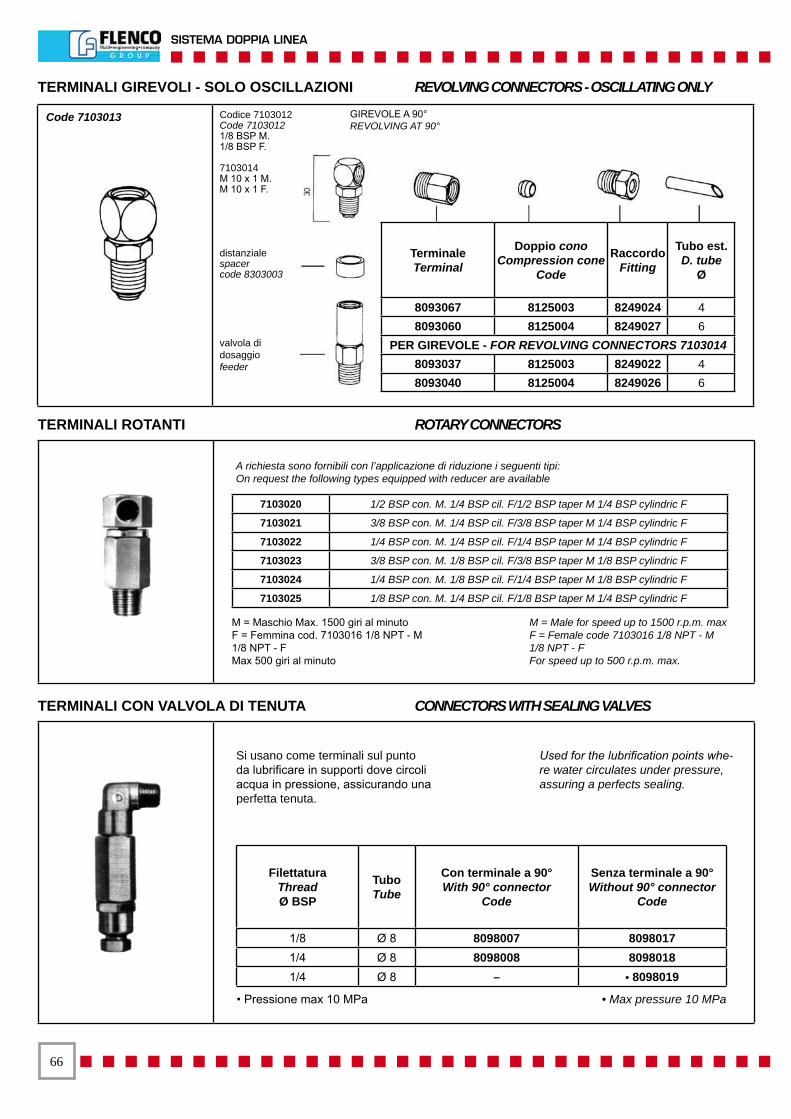
��
SISTEMA DOPPIA LINEA
TerminaleTerminal
Doppio conoCompression cone
Code
Raccordo Fitting
Tubo est.D. tube
Ø
8093067 8125003 8249024 4 8093060 8125004 8249027 6
PER GIREVOLE - FOR REVOLVING CONNECTORS 7103014 8093037 8125003 8249022 4 8093040 8125004 8249026 6
Si usano come terminali sul punto da lubrificare in supporti dove circoli acqua in pressione, assicurando una perfetta tenuta.
Used for the lubrification points whe-re water circulates under pressure, assuring a perfects sealing.
Filettatura Thread Ø BSP
Tubo Tube
Con terminale a 90°With 90° connector
Code
Senza terminale a 90°Without 90° connector
Code
1/8 Ø 8 8098007 8098017 1/4 Ø 8 8098008 8098018 1/4 Ø 8 – • 8098019
• Pressione max 10 MPa • Max pressure 10 MPa
7103020 1/2 BSP con. M. 1/4 BSP cil. F/1/2 BSP taper M 1/4 BSP cylindric F
7103021 3/8 BSP con. M. 1/4 BSP cil. F/3/8 BSP taper M 1/4 BSP cylindric F
7103022 1/4 BSP con. M. 1/4 BSP cil. F/1/4 BSP taper M 1/4 BSP cylindric F
7103023 3/8 BSP con. M. 1/8 BSP cil. F/3/8 BSP taper M 1/8 BSP cylindric F
7103024 1/4 BSP con. M. 1/8 BSP cil. F/1/4 BSP taper M 1/8 BSP cylindric F
7103025 1/8 BSP con. M. 1/4 BSP cil. F/1/8 BSP taper M 1/4 BSP cylindric F
A richiesta sono fornibili con l’applicazione di riduzione i seguenti tipi:On request the following types equipped with reducer are available
M = Maschio Max. 1500 giri al minutoF = Femmina cod. 7103016 1/8 NPT - M 1/8 NPT - FMax 500 giri al minuto
M = Male for speed up to 1500 r.p.m. maxF = Female code 7103016 1/8 NPT - M 1/8 NPT - FFor speed up to 500 r.p.m. max.
TERMINALI CON VALVOLA DI TENUTA CONNECTORS WITH SEALING VALVES
TERMINALI ROTANTI ROTARY CONNECTORS
TERMINALI GIREVOLI - SOLO OSCILLAZIONI REVOLVING CONNECTORS - OSCILLATING ONLY
Code 7103013 Codice 7103012 Code 7103012 1/8 BSP M. 1/8 BSP F.
7103014 M 10 x 1 M. M 10 x 1 F.
distanzialespacer code 8303003
valvola didosaggiofeeder
GIREVOLE A 90°REVOLVING AT 90°
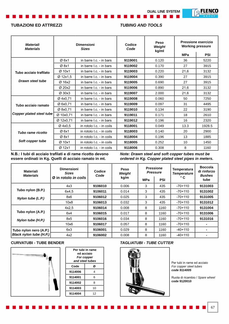
��
DUAL LINE SYSTEM
MaterialiMaterials
DimensioniSizes
CodiceCode
PesoWeightkg/ml
Pressione esercizioWorking pressure
MPa PSI
Tubo acciaio trafilato
Drawn steel tube
Ø 6x1 in barre I.c. - in bars 9119001 0.120 36 5220 Ø 8x1 in barre I.c. - in bars 9119002 0.170 27 3915
Ø 10x1 in barre I.c. - in bars 9119003 0.220 21,6 3132 Ø 12x1,5 in barre I.c. - in bars 9119004 0.390 27 3915 Ø 16x2 in barre I.c. - in bars 9119005 0.690 27 3915 Ø 20x2 in barre I.c. - in bars 9119006 0.890 21,6 3132 Ø 30x3 in barre I.c. - in bars 9119007 2.000 21,6 3132
Tubo acciaio ramato
Copper plated steel tube
Ø 4x0,71 in barre I.c. - in bars 9119008 0.060 50 7250 Ø 6x0,71 in barre I.c. - in bars 9119009 0.097 31 4495 Ø 8x0,71 in barre I.c. - in bars 9119010 0.134 22 3190
Ø 10x0,71 in barre I.c. - in bars 9119011 0.171 18 2610 Ø 12x0,71 in barre I.c. - in bars 9119012 0.196 16 2320
Tubo rame ricotto
Soft copper tube
Ø 4x0,5 in rotolo I.c. - in coils 9118001 0.049 13.3 1928.5 Ø 6x1 in rotolo I.c. - in coils 9118003 0.140 20 2900 Ø 8x1 in rotolo I.c. - in coils 9118004 0.196 13 1885
Ø 10x1 in rotolo I.c. - in coils 9118005 0.252 10 1450 Ø 12x1 in rotolo I.c. - in coils 9118006 0.308 8 1160
MaterialiMaterials
DimensioniSizes
Ø in rotolo in coilsCodiceCode
PesoWeightkg/m
PressionePressure
TemperaturaTemperature
° C
Boccoladi rinforzo
Bushestube MPa PSI
Tubo nylon (B.P.)
Nylon tube (L.P.)
4x3 9106010 0.006 3 435 -70+110 9131003 6x4,5 9106011 0.014 3 435 -70+110 9131002 8x6 9106012 0.025 3 435 -70+110 9131005
10x8 9106013 0.032 3 435 -70+110 9131012
Tubo nylon (A.P.)
Nylon tube (H.P.)
4x2,5 9106014 0.008 8 1160 -70+110 9131004 6x4 9106015 0.017 8 1160 -70+110 9131006 8x5 9106016 0.034 8 1160 -70+110 9131016
10x6 9106017 0.057 8 1160 -70+110 -
Tubo nylon nero (A.P.)Black nylon tube (H.P.)
6x3 9106001 0.029 8 1160 -40+110 -4x2 9106002 0.008 8 1160 -40+110 -
Per tubi in rameed acciaio For copper
and steel tubes
Code Ø
9114006 4
9114001 6
9114002 8
9114003 10
9114004 12
CURVATUBI - TUBE BENDER TAGLIATUBI - TUBE CUTTER
Per tubi in rame ed acciaioFor copper steel tubescode 9114005
Ruota di ricambio / Spare wheelcode 9120010
TUBAZIONI ED ATTREZZI TUBING AND TOOLS
N.B.: I tubi di acciaio trafilati e di rame ricotto devono essere ordinati in Kg. Quelli di acciaio ramato in mt.
Note: Drawn steel and soft copper tubes must be ordered in Kg. Copper plated steel pipes in meters.
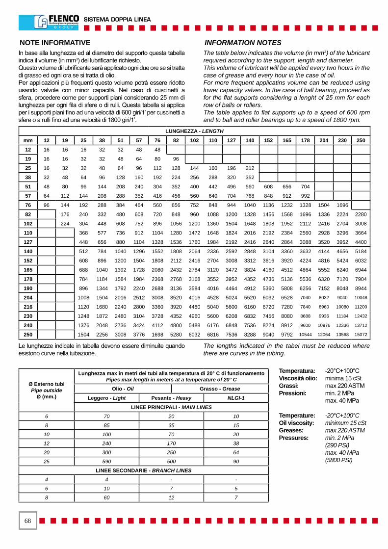
��
SISTEMA DOPPIA LINEA
NOTE INFORMATIVE INFORMATION NOTESIn base alla lunghezza ed al diametro del supporto questa tabella indica il volume (in mm3) del lubrificante richiesto.Questo volume di lubrificante sarà applicato ogni due ore se si tratta di grasso ed ogni ora se si tratta di olio.Per applicazioni più frequenti questo volume potrà essere ridotto usando valvole con minor capacità. Nel caso di cuscinetti a sfera, procedere come per supporti piani considerando 25 mm di lunghezza per ogni fila di sfere o di rulli. Questa tabella si applica per i supporti piani fino ad una velocità di 600 giri/1’ per cuscinetti a sfere o a rulli fino ad una velocità di 1800 giri/1’.
The table below indicates the volume (in mm3) of the lubricant required according to the support, length and diameter.This volume of lubricant will be applied every two hours in the case of grease and every hour in the case of oil.For more frequent applicatins volume can be reduced using lower capacity valves. In the case of ball bearing, proceed as for the flat supports considering a lenght of 25 mm for each row of balls or rollers.The table applies to flat supports up to a speed of 600 rpm and to ball and roller bearings up to a speed of 1800 rpm.
Le lunghezze indicate in tabella devono essere diminuite quando esistono curve nella tubazione.
The lengths indicated in the tabel must be reduced where there are curves in the tubing.
Temperatura: -20°C+100°CViscosità olio: minima 15 cStGrassi: max 220 ASTMPressioni: min. 2 MPa max. 40 MPa
Temperature: -20°C+100°COil viscosity: minimum 15 cStGreases: max 220 ASTMPressures: min. 2 MPa (290 PSI) max. 40 MPa (5800 PSI)
Ø Esterno tubiPipe outside
Ø (mm.)
Lunghezza max in metri dei tubi alla temperatura di 20° C di funzionamentoPipes max length in meters at a temperature of 20° C
Olio - Oil Grasso - Grease
Leggero - Light Pesante - Heavy NLGI-1
LINEE PRINCIPALI - MAIN LINES
6 70 20 10
8 85 35 15
10 100 70 20
12 240 170 38
20 300 250 64
25 590 500 90
LINEE SECONDARIE - BRANCH LINES
4 4 - -
6 10 7 5
8 60 12 7
LUNGHEZZA - LENGTH
mm 12 19 25 38 51 57 76 82 102 110 127 140 152 165 178 204 230 250
12 16 16 16 32 32 48 48
19 16 16 32 32 48 64 80 96
25 16 32 32 48 64 96 112 128 144 160 196 212
38 32 48 64 96 128 160 192 224 256 288 320 352
51 48 80 96 144 208 240 304 352 400 442 496 560 608 656 704
57 64 112 144 208 288 352 416 456 560 640 704 768 848 912 992
76 96 144 192 288 384 464 560 656 752 848 944 1040 1136 1232 1328 1504 1696
82 176 240 332 480 608 720 848 960 1088 1200 1328 1456 1568 1696 1336 2224 2280
102 224 304 448 608 752 896 1056 1200 1360 1504 1648 1808 1952 2112 2416 2704 3008
110 368 577 736 912 1104 1280 1472 1648 1824 2016 2192 2384 2560 2928 3296 3664
127 448 656 880 1104 1328 1536 1760 1984 2192 2416 2640 2864 3088 3520 3952 4400
140 512 784 1040 1296 1552 1808 2064 2336 2592 2848 3104 3360 3632 4144 4656 5184
152 608 896 1200 1504 1808 2112 2416 2704 3008 3312 3616 3920 4224 4816 5424 6032
165 688 1040 1392 1728 2080 2432 2784 3120 3472 3824 4160 4512 4864 5552 6240 6944
178 784 1184 1584 1984 2368 2768 3168 3552 3952 4352 4736 5136 5536 6320 7120 7904
190 896 1344 1792 2240 2688 3136 3584 4016 4464 4912 5360 5808 6256 7152 8048 8944
204 1008 1504 2016 2512 3008 3520 4016 4528 5024 5520 6032 6528 7040 8032 9040 10048
216 1120 1680 2240 2800 3360 3920 4480 5040 5600 6160 6720 7280 7840 8960 10080 11200
230 1248 1872 2480 3104 3728 4352 4960 5600 6208 6832 7456 8080 8688 9936 11184 12432
240 1376 2048 2736 3424 4112 4800 5488 6176 6848 7536 8224 8912 9600 10976 12336 13712
250 1504 2256 3008 3776 1698 5280 6032 6816 7536 8288 9040 9792 10544 12064 13568 15072

��
DUAL LINE SYSTEM
CLASSIFICAZIONE LUBRIFICANTE LUBRICANT CLASSIFICATION
PER LUBRIFICANTI LIQUIDI INDUSTRIALILa serie delle gradazioni di viscosità è stata fissata partendo da una successione numerica, posta in progressione matematica, che riflettesse al tempo stesso la reale situazione delle viscosità delle gradazioni esistenti in commercio.
FOR LIQUID INDUSTRIAL LUBRICANTSThe set of viscosity levels has been established according to a numeric sequence, in mathematical progression, which at the same time also reflects the effective situation of the viscosity ratings of commercially available degrees.
1 2 3 OLIO / OIL
Valore medio della viscosità
Mean viscosity
cSt a 40°C
Intervallo di viscosità in cSt a 40°C
Viscosity range in cSt at 40°CSimbolo ISOISO symbol
LEGGEROLIGHT
Minimo / Minimum Massimo / Maximum
2,2 1,98 2,42 ISO VG 23,2 2,88 3,52 ISO VG 34,6 4,14 5,06 ISO VG 56,8 6,12 7,48 ISO VG 710 9,00 11,0 ISO VG 1015 13,5 16,5 ISO VG 1522 19,8 24,2 ISO VG 2232 28,8 35,2 ISO VG 3246 41,4 50,6 ISO VG 4668 61,2 74,8 ISO VG 68
100 90,0 110 ISO VG 100150 135 165 ISO VG 150220 198 242 ISO VG 220
PESANTEHEAVY
320 288 352 ISO VG 320460 414 506 ISO VG 460680 612 748 ISO VG 680
1000 900 1100 ISO VG 10001500 1350 1650 ISO VG 1500
Grado NLGINLGI degree
lavorata ASTM in 1/10 di mmASTM penetration in 1/10 of mm
GrassoGrease
000 445-475 FluidoFluid00 400-430
0 355-385
1 310-340
SolidoSolid
2 265-295
3 220-250
4 175-205
5 130-160
6 85-115
NLGINational Lubricating Grease Institute
ASTMAmerican Society for Testing and Materials
GRASSO - CORRISPONDENZA NLGI - ASTM GREASE - NLGI - ASTM CORRESPONDENCE
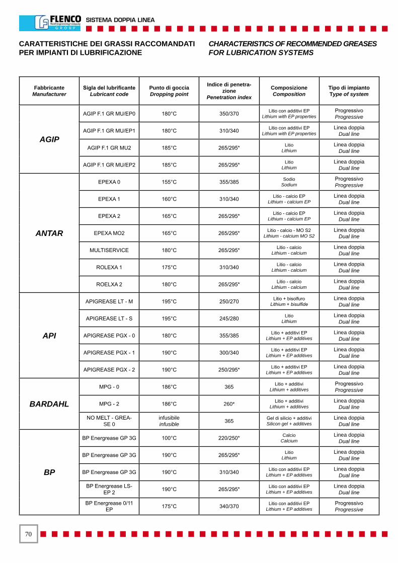
�0
SISTEMA DOPPIA LINEA
CARATTERISTICHE DEI GRASSI RACCOMANDATIPER IMPIANTI DI LUBRIFICAZIONE
CHARACTERISTICS OF RECOMMENDED GREASESFOR LUBRICATION SYSTEMS
FabbricanteManufacturer
Sigla del lubrificanteLubricant code
Punto di gocciaDropping point
Indice di penetra-zione
Penetration index
ComposizioneComposition
Tipo di impiantoType of system
AGIP
AGIP F.1 GR MU/EP0 180°C 350/370 Litio con additivi EPLithium with EP properties
ProgressivoProgressive
AGIP F.1 GR MU/EP1 180°C 310/340 Litio con additivi EPLithium with EP properties
Linea doppiaDual line
AGIP F.1 GR MU2 185°C 265/295* LitioLithium
Linea doppiaDual line
AGIP F.1 GR MU/EP2 185°C 265/295* LitioLithium
Linea doppiaDual line
ANTAR
EPEXA 0 155°C 355/385 SodioSodium
ProgressivoProgressive
EPEXA 1 160°C 310/340 Litio - calcio EPLithium - calcium EP
Linea doppiaDual line
EPEXA 2 165°C 265/295* Litio - calcio EPLithium - calcium EP
Linea doppiaDual line
EPEXA MO2 165°C 265/295* Litio - calcio - MO S2Lithium - calcium MO S2
Linea doppiaDual line
MULTISERVICE 180°C 265/295* Litio - calcioLithium - calcium
Linea doppiaDual line
ROLEXA 1 175°C 310/340 Litio - calcioLithium - calcium
Linea doppiaDual line
ROELXA 2 180°C 265/295* Litio - calcioLithium - calcium
Linea doppiaDual line
API
APIGREASE LT - M 195°C 250/270 Litio + bisolfuroLithium + bisulfide
Linea doppiaDual line
APIGREASE LT - S 195°C 245/280 LitioLithium
Linea doppiaDual line
APIGREASE PGX - 0 180°C 355/385 Litio + additivi EPLithium + EP additives
Linea doppiaDual line
APIGREASE PGX - 1 190°C 300/340 Litio + additivi EPLithium + EP additives
Linea doppiaDual line
APIGREASE PGX - 2 190°C 250/295* Litio + additivi EPLithium + EP additives
Linea doppiaDual line
BARDAHL
MPG - 0 186°C 365 Litio + additiviLithium + additives
ProgressivoProgressive
MPG - 2 186°C 260* Litio + additiviLithium + additives
Linea doppiaDual line
NO MELT - GREA-SE 0
infusibileinfusible 365 Gel di silicio + additivi
Silicon gel + additivesLinea doppia
Dual line
BP
BP Energrease GP 3G 100°C 220/250* CalcioCalcium
Linea doppiaDual line
BP Energrease GP 3G 190°C 265/295* LitioLithium
Linea doppiaDual line
BP Energrease GP 3G 190°C 310/340 Litio con additivi EPLithium + EP additives
Linea doppiaDual line
BP Energrease LS-EP 2 190°C 265/295* Litio con additivi EP
Lithium + EP additivesLinea doppia
Dual line
BP Energrease 0/11 EP 175°C 340/370 Litio con additivi EP
Lithium + EP additivesProgressivoProgressive

��
DUAL LINE SYSTEM
CARATTERISTICHE DEI GRASSI RACCOMANDATIPER IMPIANTI DI LUBRIFICAZIONE
CHARACTERISTICS OF RECOMMENDED GREASESFOR LUBRICATION SYSTEMS
FabbricanteManufacturer
Sigla del lubrificanteLubricant code
Punto di gocciaDropping point
Indice di penetra-zione
Penetration index
ComposizioneComposition
Tipo di impiantoType of system
B.R.
BR FIRE GREASE 1 infusibileinfusible 290/310* Silicio piombo
Silicon leadLinea doppia
Dual line
BR GREASE X1 180°C 350/380 Litio calcio piomboLithium calcium lead
Linea doppiaDual line
BR GREASE X2 180°C 310/350 Litio calcio piomboLithium calcium lead
Linea doppiaDual line
BR Grease EP 1 Extra 180°C 310/340 Litio con additivi EPLithium with EP additives
Linea doppiaDual line
CASTROL
SPHEEROL APT 1 183°C 310/340 LitioLithium
Linea doppiaDual line
SPHEEROL APT 2 183°C 265/295* LitioLithium
Linea doppiaDual line
SPHEEROL BN infusibileinfusible 265/295* Bentone
BentoneLinea doppia
Dual line
SPHEEROL EPL 0 175°C 350/360 Litio con additivi EPLithium with EP additives
ProgressivoProgressive
SPHEEROL EPL 1 183°C 310/340 Litio con additivi EPLithium with EP additives
Linea doppiaDual line
SPHEEROL EPL 2 183°C 265/295* Litio con additivi EPLithium with EP additives
Linea doppiaDual line
CHEVRON
Dura-Lith Grease EP 0 170°C 370 LitioLithium
ProgressivoProgressive
Dura-Lith Grease EP 2 180°C 280* LitioLithium
Linea doppiaDual line
Multi-Move Grease 1 290°C 330* Calcio complessoComplex calcium
Linea doppiaDual line
REINER
STABYL A-2 EP 190°C 265/2/5 Litio con additivi EPLithium with EP additives
Linea doppiaDual line
STABYL L-TS MO 185°C 265/295 Litio + Semisin. + MoS2Lithium + semisin. + MoS2
Linea doppiaDual line
ALMETYN 1 260°C 310/340 Al. comp. + additivi EPAl comp. + EP additives
ProgressivoProgressive
ALMETYN 2 270°C 265/295 Al. comp. + additivi EPAl comp. + EP additives
ProgressivoProgressive
URETHYN E/M 2 260°C 265/295 Sintetico + additivi EPSynthetic + EP additives
ProgressivoProgressive
URETHYN E 2 257°C 265/295 Sintetico + additivi EPSynthetic + EP additives
Linea doppiaDual line
GERALYN 2 240 265/295 Al. comp.Al. comp.
Linea doppiaDual line
GERALYN P 2 senzawithout 265/295 Betone + sintetico
Betone + syntheticLinea doppia
Dual line
GLEITMO
GLEITMO 500 185°C 265/295 Litio + MoS2Lithium + MoS2
Linea doppiaDual line
GLEITMO 585 M 170°C 265/295 Litio + solidi bianchiLithium + MoS2
Linea doppiaDual line
GLEITMO 805 160°C 265/295 Litio + solidi bianchiLithium + white solid
Linea doppiaDual line
GLEITMO 523 220°C 265/295 Litio complessoComplex lithium
Linea doppiaDual line

��
SISTEMA DOPPIA LINEA
CARATTERISTICHE DEI GRASSI RACCOMANDATIPER IMPIANTI DI LUBRIFICAZIONE
CHARACTERISTICS OF RECOMMENDED GREASESFOR LUBRICATION SYSTEMS
FabbricanteManufacturer
Sigla del lubrificanteLubricant code
Punto di gocciaDropping point
Indicedi penetrazione
Penetration index
ComposizioneComposition
Tipo di impiantoType of system
ESSO
BEACON EP 1 182°C 300/330* Litio con proprietà IPLithium with IP properties
Linea doppia - ProgressivoDual line - Progressive
CAZARK 1 100°C 310/340* CalcioCalcium
Linea doppia - ProgressivoDual line - Progressive
CAZARK 2 102°C 265/295* CalcioCalcium
Linea doppiaDual line
BEACON EP 0 180°C 355/385 LitioLithium
ProgressivoProgressive
EUROIL
EURO EP 0 100°C 360/370 Calcio+piombo+add. EPCalcium+lead+EP add.
Linea doppia - ProgressivoDual line - Progressive
EUROLITEX EP 1 180°C 360/345 Litio con additivi EPLithium with EP additives
Linea doppia - ProgressivoDual line - Progressive
EUROLITEW EP 0 180°C 380/385 LitioLithium
ProgressivoProgressive
OLIO FIAT GrassoLAMBDA 1 EP 185°C 310/340 Litio+additivi EP
Lithium + EP additivesLinea doppia - Progressivo
Dual line - Progressive
FINA
FINA BENTEX 0 infusibileinfusible 355/385 Bentone con additivi
Bentone with additivesProgressivoProgressive
FINA 5628 240°C 280/290* LitioLithium
Linea doppia - ProgressivoDual line - Progressive
FINA MARSON HTL 1 180/190°C 32/330 LitioLithium
Linea doppia - ProgressivoDual line - Progressive
FINA MARSON LM 180°C 280/305* Litio con additiviLithium with additives
Linea doppia - ProgressivoDual line - Progressive
GAZELLE
GUN GREASE EP 1 170°C 350/370 Litio con additivi EPLithium with EP additives
ProgressivoProgressive
GUN GREASE EP 1 180°C 310/340 Litio con additivi EPLithium with EP additives
Linea doppia - ProgressivoDual line - Progressive
GUN GREASE 301 180°C 310/340 Litio con additiviLithium with additives
Linea doppia - ProgressivoDual line - Progressive
HARRISON
GREASE 429/0 95°C 330/360 Base classicaClassic base
Linea doppia - ProgressivoDual line - Progressive
GREASE 430 EP 0 175°C 330/360 Litio+additivi EPLithium + EP additives
Linea doppia - ProgressivoDual line - Progressive
GREASE 433/3 180°C 300/330 LitioLithium
Linea doppiaDual line
HOUGRTON
COSMOLUBE MF 200°C 360 Litio bisolfuro MoLithium bisulfide Mo
ProgressivoProgressive
KR380 AA MF infusibileinfusible 320 Sintetico bisolfuro Mo
Synthetic bisulfide MoLinea doppia - Progressivo
Dual line - Progressive
STABURAGSB 15/A400 280°C 400 Sodio
SodiumProgressivoProgressive
STRABURAGSB 30/A280
infusibileinfusible 270/280* Addensato
Treckening agentLinea doppia - Progressivo
Dual line - Progressive

��
DUAL LINE SYSTEM
CARATTERISTICHE DEI GRASSI RACCOMANDATIPER IMPIANTI DI LUBRIFICAZIONE
CHARACTERISTICS OF RECOMMENDED GREASESFOR LUBRICATION SYSTEMS
FabbricanteManufacturer
Sigla del lubrificanteLubricant code
Punto di gocciaDropping point
Indice di penetra-zione
Penetration index
ComposizioneComposition
Tipo di impiantoType of system
EUROIL
GRASSO STELI SC/TC 2009210°C 280/290* Litio
LithiumLinea doppia
Dual line
GRASSO TECALEM 120/130°C 280/290* AlluminioAluminum
Linea doppiaDual line
GR. TECALEM UT/TC 100/110°C 380/400* AlluminioAluminum
ProgressivoProgressive
MOBIL
Mobilgrease Larital 2 150°C 265/295* LitioLithium
Linea doppiaDual line
Mobilgrease Special 170°C 275/305* LitioLithium
Linea doppia - ProgressivoDual line - Progressive
Mobilplex 46 260°C 310/340* ComplessoComplex
Linea doppia - ProgressivoDual line - Progressive
Mobilplex 47 230°C 295/325 ComplessoComplex
Linea doppia - ProgressivoDual line - Progressive
Mobiltemp Grease 78 78 260°C 295/340 Sapone ispes. infusib.Infusible ispes. soap
Linea doppia - ProgressivoDual line - Progressive
Mobilux Grease 180°C 265/295* LitioLithium
Linea doppiaDual line
Sovarex Grease L 0 225°C 370/390 Calcio piombo additiviCalcium lead additives
ProgressivoProgressive
Sovarex Grease L 1 230°C 340/370 Calcio piombo additiviCalcium lead additives
Linea doppia - ProgressivoDual line - Progressive
MOLY
LMP/180/0 191°C 355/385 Litio+Mo S2Lithium+Mo S2
Linea doppia - ProgressivoDual line - Progressive
LMP/180/1 191°C 310/340 Litio+Mo S2Lithium+Mo S2
Linea doppia - ProgressivoDual line - Progressive
LMP/180/2 191°C 165/295* Litio+Mo S2Lithium+Mo S2
Linea doppiaDual line
MOLIKOTE
BR2 185°C 265/295* LitioLithium
Linea doppiaDual line
FB 180 - 265/295* Bisolfuro MoBisulfide Mo
Linea doppiaDual line
LONGTERM W 2 195°C 265/295* Litio+ossidi solidi bianchiLithium+solid white oxides
Linea doppiaDual line
LONGTERM 1-2 175°C 265/295* Litio+bisolfuro MoLithium+bisulfide Mo
Linea doppia - ProgressivoDual line - Progressive
1132 - 245/275* Sintetico bisolfuroSynthetic bisulfide
Linea doppia - ProgressivoDual line - Progressive
OLEOBLITZEVERLUB 5 F - 310/340 Olio addensato
Thickened oilLinea doppia - Progressivo
Dual line - Progressive
SFERUL LF 180°C 310/340 LitioLithium
Linea doppia - ProgressivoDual line - Progressive
ROL OIL
LITEEX - EP/1 180°C 310/340 Litio+additivi EPLithium+EP additives
Linea doppia - ProgressivoDual line - Progressive
MATIC - EP/0 100°C 355/385 Calcio+additivi EPCalcium+EP additives
Linea doppia - ProgressivoDual line - Progressive
MATIC - EP/1 100°C 310/340 Calcio+additivi EPCalcium+EP additives
Linea doppia - ProgressivoDual line - Progressive
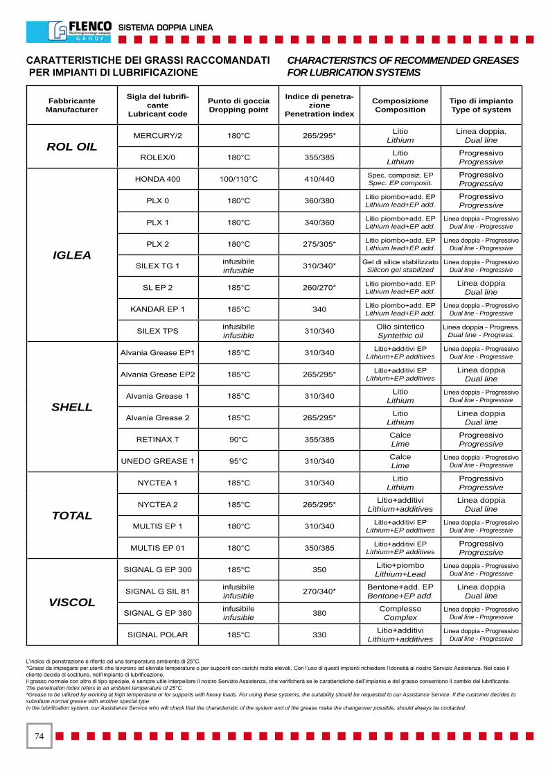
��
SISTEMA DOPPIA LINEA
CARATTERISTICHE DEI GRASSI RACCOMANDATI PER IMPIANTI DI LUBRIFICAZIONE
CHARACTERISTICS OF RECOMMENDED GREASESFOR LUBRICATION SYSTEMS
FabbricanteManufacturer
Sigla del lubrifi-cante
Lubricant code
Punto di gocciaDropping point
Indice di penetra-zione
Penetration index
ComposizioneComposition
Tipo di impiantoType of system
ROL OILMERCURY/2 180°C 265/295* Litio
LithiumLinea doppia.
Dual line
ROLEX/0 180°C 355/385 LitioLithium
ProgressivoProgressive
IGLEA
HONDA 400 100/110°C 410/440 Spec. composiz. EPSpec. EP composit.
ProgressivoProgressive
PLX 0 180°C 360/380 Litio piombo+add. EPLithium lead+EP add.
ProgressivoProgressive
PLX 1 180°C 340/360 Litio piombo+add. EPLithium lead+EP add.
Linea doppia - ProgressivoDual line - Progressive
PLX 2 180°C 275/305* Litio piombo+add. EPLithium lead+EP add.
Linea doppia - ProgressivoDual line - Progressive
SILEX TG 1 infusibileinfusible 310/340* Gel di silice stabilizzato
Silicon gel stabilizedLinea doppia - Progressivo
Dual line - Progressive
SL EP 2 185°C 260/270* Litio piombo+add. EPLithium lead+EP add.
Linea doppiaDual line
KANDAR EP 1 185°C 340 Litio piombo+add. EPLithium lead+EP add.
Linea doppia - ProgressivoDual line - Progressive
SILEX TPS infusibileinfusible 310/340 Olio sintetico
Syntethic oilLinea doppia - Progress.
Dual line - Progress.
SHELL
Alvania Grease EP1 185°C 310/340 Litio+additivi EPLithium+EP additives
Linea doppia - ProgressivoDual line - Progressive
Alvania Grease EP2 185°C 265/295* Litio+additivi EPLithium+EP additives
Linea doppiaDual line
Alvania Grease 1 185°C 310/340 LitioLithium
Linea doppia - ProgressivoDual line - Progressive
Alvania Grease 2 185°C 265/295* LitioLithium
Linea doppiaDual line
RETINAX T 90°C 355/385 CalceLime
ProgressivoProgressive
UNEDO GREASE 1 95°C 310/340 CalceLime
Linea doppia - ProgressivoDual line - Progressive
TOTAL
NYCTEA 1 185°C 310/340 LitioLithium
ProgressivoProgressive
NYCTEA 2 185°C 265/295* Litio+additiviLithium+additives
Linea doppiaDual line
MULTIS EP 1 180°C 310/340 Litio+additivi EPLithium+EP additives
Linea doppia - ProgressivoDual line - Progressive
MULTIS EP 01 180°C 350/385 Litio+additivi EPLithium+EP additives
ProgressivoProgressive
VISCOL
SIGNAL G EP 300 185°C 350 Litio+piomboLithium+Lead
Linea doppia - ProgressivoDual line - Progressive
SIGNAL G SIL 81 infusibileinfusible 270/340* Bentone+add. EP
Bentone+EP add.Linea doppia
Dual line
SIGNAL G EP 380 infusibileinfusible 380 Complesso
ComplexLinea doppia - Progressivo
Dual line - Progressive
SIGNAL POLAR 185°C 330 Litio+additiviLithium+additives
Linea doppia - ProgressivoDual line - Progressive
L’indice di penetrazione è riferito ad una temperatura ambiente di 25°C.*Grassi da impiegarsi per utenti che lavorano ad elevate temperature o per supporti con carichi molto elevati. Con l’uso di questi impianti richiedere l’idoneità al nostro Servizio Assistenza. Nel caso il cliente decida di sostituire, nell’impianto di lubrificazione,il grasso normale con altro di tipo speciale, è sempre utile interpellare il nostro Servizio Assistenza, che verificherà se le caratteristiche dell’impianto e del grasso consentono il cambio del lubrificante.The penetration index refers to an ambient temperature of 25°C.*Grease to be utilized by working at high temperature or for supports with heavy loads. For using these systems, the suitability should be requested to our Assistance Service. If the customer decides to substitute normal grease with another special typein the lubrification system, our Assistance Service who will check that the characteristic of the system and of the grease make the changeover possible, should always be contacted.
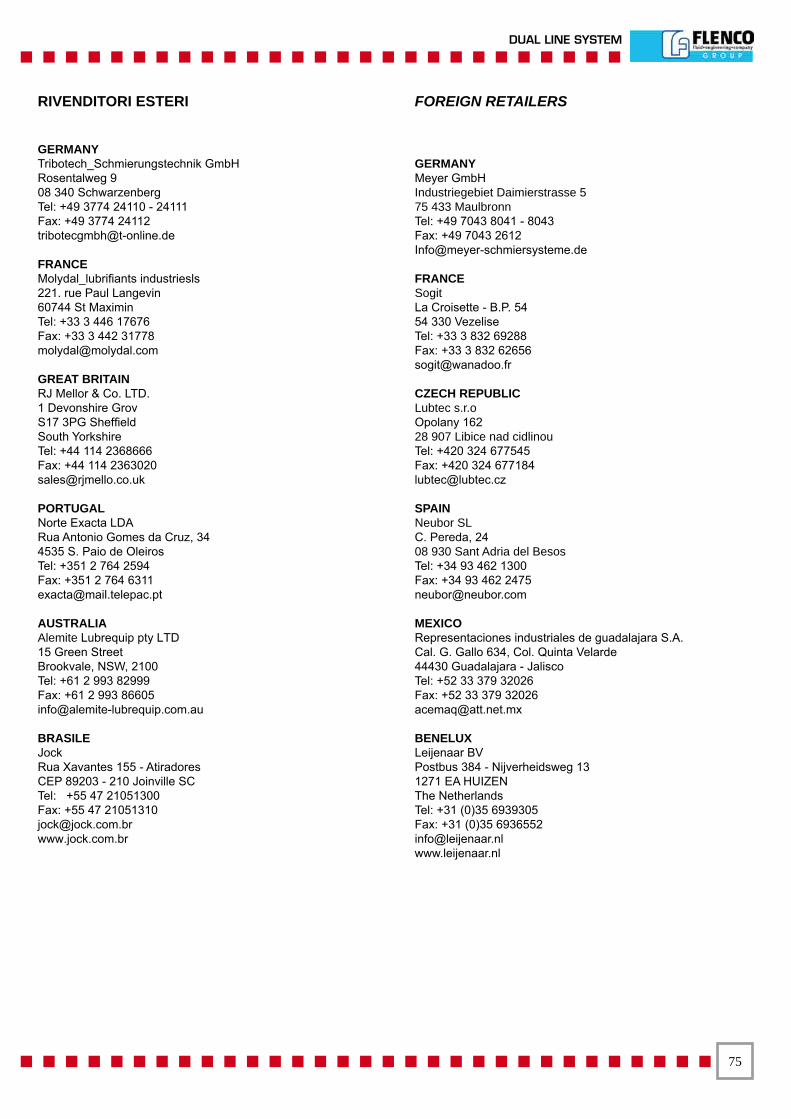
��
DUAL LINE SYSTEM
GERMANYTribotech_Schmierungstechnik GmbHRosentalweg 908 340 SchwarzenbergTel: +49 3774 24110 - 24111Fax: +49 3774 [email protected]
FRANCEMolydal_lubrifiants industriesls221. rue Paul Langevin60744 St MaximinTel: +33 3 446 17676Fax: +33 3 442 [email protected]
GREAT BRITAINRJ Mellor & Co. LTD.1 Devonshire GrovS17 3PG SheffieldSouth YorkshireTel: +44 114 2368666Fax: +44 114 [email protected]
PORTUGALNorte Exacta LDARua Antonio Gomes da Cruz, 344535 S. Paio de OleirosTel: +351 2 764 2594Fax: +351 2 764 [email protected]
AUSTRALIAAlemite Lubrequip pty LTD15 Green StreetBrookvale, NSW, 2100Tel: +61 2 993 82999Fax: +61 2 993 [email protected]
BRASILEJockRua Xavantes 155 - AtiradoresCEP 89203 - 210 Joinville SCTel: +55 47 21051300Fax: +55 47 [email protected]
GERMANYMeyer GmbHIndustriegebiet Daimierstrasse 575 433 MaulbronnTel: +49 7043 8041 - 8043Fax: +49 7043 [email protected]
FRANCESogitLa Croisette - B.P. 5454 330 VezeliseTel: +33 3 832 69288Fax: +33 3 832 [email protected]
CZECH REPUBLICLubtec s.r.oOpolany 16228 907 Libice nad cidlinouTel: +420 324 677545Fax: +420 324 [email protected]
SPAINNeubor SLC. Pereda, 2408 930 Sant Adria del BesosTel: +34 93 462 1300Fax: +34 93 462 [email protected]
MEXICORepresentaciones industriales de guadalajara S.A.Cal. G. Gallo 634, Col. Quinta Velarde44430 Guadalajara - JaliscoTel: +52 33 379 32026Fax: +52 33 379 [email protected]
BENELUXLeijenaar BVPostbus 384 - Nijverheidsweg 131271 EA HUIZENThe NetherlandsTel: +31 (0)35 6939305Fax: +31 (0)35 [email protected]
RIVENDITORI ESTERI FOREIGN RETAILERS


Cat. Code 3320950 - Edition 06/2007
www.flenco.com
WORKSHOP EAST EUROPERomania - Brasov
Sos. Cristianului, 1-3Tel. +40.0368.422.170Fax +40.0368.422.172e-mail: [email protected]
OFFICE - GERMANYPrinzenallee, 7
40549 DusseldorfTel. +49.211.523.91.183Mobile +49.173.1683.422Fax +49.211.523.91.200e-mail: [email protected]
WORKSHOP SLOVENIJARogozniska, 14 - 2250 PTUJ
Tel. +386.2.749.27.30Fax +386.2.749.27.38e-mail: [email protected]
HEAD QUARTER ITALY10051 AVIGLIANA (TO)
Corso Torino, 2Tel. +39.011.9330.611Fax +39.011.9367.717e-mail: [email protected]
WORKSHOP ITALY13039 Trino (VERCELLI)
S.S. 31 bis Km 31Tel. +39.011.9330.611Fax +39.0161.80.15.23e-mail: [email protected]
OFFICE - 50045 FIRENZEVia dei Giunchi, 56/58
Tel. +39.011.9330.611Fax +39.055.319.374e-mail: [email protected]
OFFICE - 20100 MILANOVia Santa Maria Rossa, 8
Tel. +39.02.2630.6266Fax +39.02.2630.6274e-mail: [email protected]
WORKSHOP CHINA438, Zhu Jang (Z) Road Beilun Area
31580 NINGBO(Zheijang Province - PRC)
Tel. +86.574.8689.7909Fax +86.574.8689.7939e-mail: [email protected]
WORKSHOP MEXICOFlenco de Mexico S.A. de C.V.
FME 980930 T9AAv. 16 de Septiembre, 5
Barrio de SantiaguitoTultitlan Edo. de Mexico
C.P. 54900Tel. +52.55.5899.6532Fax +52.55.5899.6331e-mail: [email protected]