Embed Size (px)
Citation preview
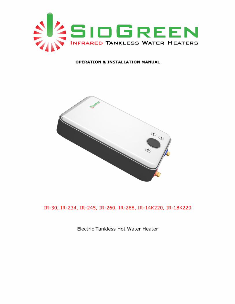
OPERATION & INSTALLATION MANUAL
IR-30, IR-234, IR-245, IR-260, IR-288, IR-14K220, IR-18K220
Electric Tankless Hot Water Heater
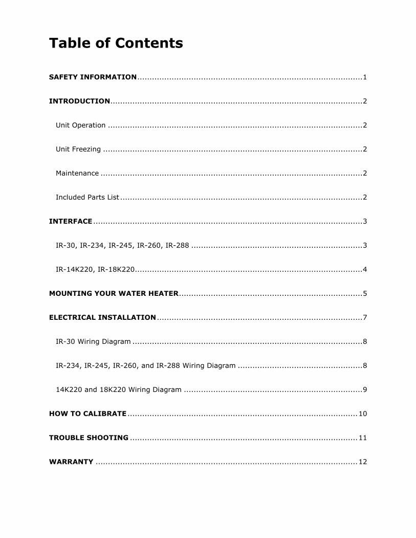
Table of Contents
SAFETY INFORMATION ............................................................................................ 1
INTRODUCTION....................................................................................................... 2
Unit Operation ........................................................................................................ 2
Unit Freezing .......................................................................................................... 2
Maintenance ........................................................................................................... 2
Included Parts List ................................................................................................... 2
INTERFACE .............................................................................................................. 3
IR-30, IR-234, IR-245, IR-260, IR-288 ...................................................................... 3
IR-14K220, IR-18K220............................................................................................. 4
MOUNTING YOUR WATER HEATER ........................................................................... 5
ELECTRICAL INSTALLATION .................................................................................... 7
IR-30 Wiring Diagram .............................................................................................. 8
IR-234, IR-245, IR-260, and IR-288 Wiring Diagram ................................................... 8
14K220 and 18K220 Wiring Diagram ......................................................................... 9
HOW TO CALIBRATE .............................................................................................. 10
TROUBLE SHOOTING ............................................................................................. 11
WARRANTY ........................................................................................................... 12

Page | 1
Thank you for choosing SioGreen products. The most advanced tankless water heaters in the world today using quartz technology and true modulation. All of our products are made with the highest-grade materials and professionally assembled. We strive to satisfy each customer with our unit’s superior quality, longevity, and the modern design of all our products.Before the use of the unit, please carefully read and understand the manual. It contains important information regarding the correct use and care of the unit.
SAFETY INFORMATION
IT IS IMPORTANT TO COMPLETELY READ AND UNDERSTAND THE INSTALLATION PROCEDURES BEFORE CONTINUING THE INSTALLATION. FAILURE TO FOLLOW THESE INSTRUCTIONS MAY RESULT IN PROPERTY DAMAGE, SERIOUS BODILY INJURY, OR DEATH. THIS PRODUCT SHOULD BE INSTALLED BY A LICENSED ELECTRICIAN AND PLUMBER IN ACCORDANCE WITH ALL NATIONAL, STATE, AND LOCAL ELECTRICAL & PLUMBING CODES. Keep this manual in a convenient place for future reference.
DANGER! WATER TEMPERATURE SAFETY SETTING Safety is our primary goal when selecting the water temperature. Any temperature above 120°F can cause serious scalding or death. Energy conservation is a factor to be considered when selecting the water temperature. Setting the water heater’s thermostat to a lower setting will allow a higher flow rate and use less energy.
Check our website, www.SioGreenUSA.com for the latest version of the Installation & User Manual.
Page | 2
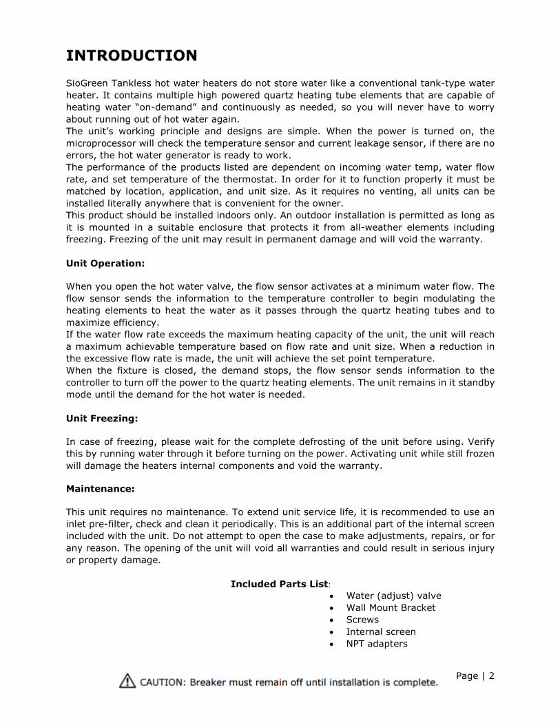
INTRODUCTION SioGreen Tankless hot water heaters do not store water like a conventional tank-type water heater. It contains multiple high powered quartz heating tube elements that are capable of heating water “on-demand” and continuously as needed, so you will never have to worry about running out of hot water again. The unit’s working principle and designs are simple. When the power is turned on, the microprocessor will check the temperature sensor and current leakage sensor, if there are no errors, the hot water generator is ready to work. The performance of the products listed are dependent on incoming water temp, water flow rate, and set temperature of the thermostat. In order for it to function properly it must be matched by location, application, and unit size. As it requires no venting, all units can be installed literally anywhere that is convenient for the owner. This product should be installed indoors only. An outdoor installation is permitted as long as it is mounted in a suitable enclosure that protects it from all-weather elements including freezing. Freezing of the unit may result in permanent damage and will void the warranty. Unit Operation: When you open the hot water valve, the flow sensor activates at a minimum water flow. The flow sensor sends the information to the temperature controller to begin modulating the heating elements to heat the water as it passes through the quartz heating tubes and to maximize efficiency. If the water flow rate exceeds the maximum heating capacity of the unit, the unit will reach a maximum achievable temperature based on flow rate and unit size. When a reduction in the excessive flow rate is made, the unit will achieve the set point temperature. When the fixture is closed, the demand stops, the flow sensor sends information to the controller to turn off the power to the quartz heating elements. The unit remains in it standby mode until the demand for the hot water is needed. Unit Freezing: In case of freezing, please wait for the complete defrosting of the unit before using. Verify this by running water through it before turning on the power. Activating unit while still frozen will damage the heaters internal components and void the warranty. Maintenance: This unit requires no maintenance. To extend unit service life, it is recommended to use an inlet pre-filter, check and clean it periodically. This is an additional part of the internal screen included with the unit. Do not attempt to open the case to make adjustments, repairs, or for any reason. The opening of the unit will void all warranties and could result in serious injury or property damage.
Included Parts List:
• Water (adjust) valve • Wall Mount Bracket • Screws • Internal screen • NPT adapters
Page | 3
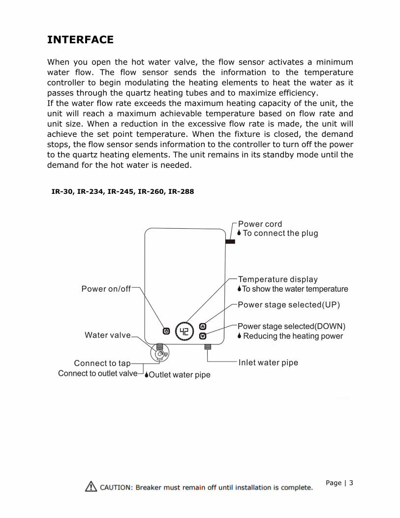
INTERFACE When you open the hot water valve, the flow sensor activates a minimum water flow. The flow sensor sends the information to the temperature controller to begin modulating the heating elements to heat the water as it passes through the quartz heating tubes and to maximize efficiency. If the water flow rate exceeds the maximum heating capacity of the unit, the unit will reach a maximum achievable temperature based on flow rate and unit size. When a reduction in the excessive flow rate is made, the unit will achieve the set point temperature. When the fixture is closed, the demand stops, the flow sensor sends information to the controller to turn off the power to the quartz heating elements. The unit remains in its standby mode until the demand for the hot water is needed. IR-30, IR-234, IR-245, IR-260, IR-288
Page | 4
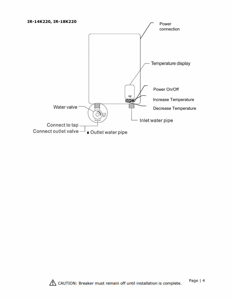
IR-14K220, IR-18K220
Power On/Off
Increase Temperature
Decrease Temperature
Power connection
Page | 5
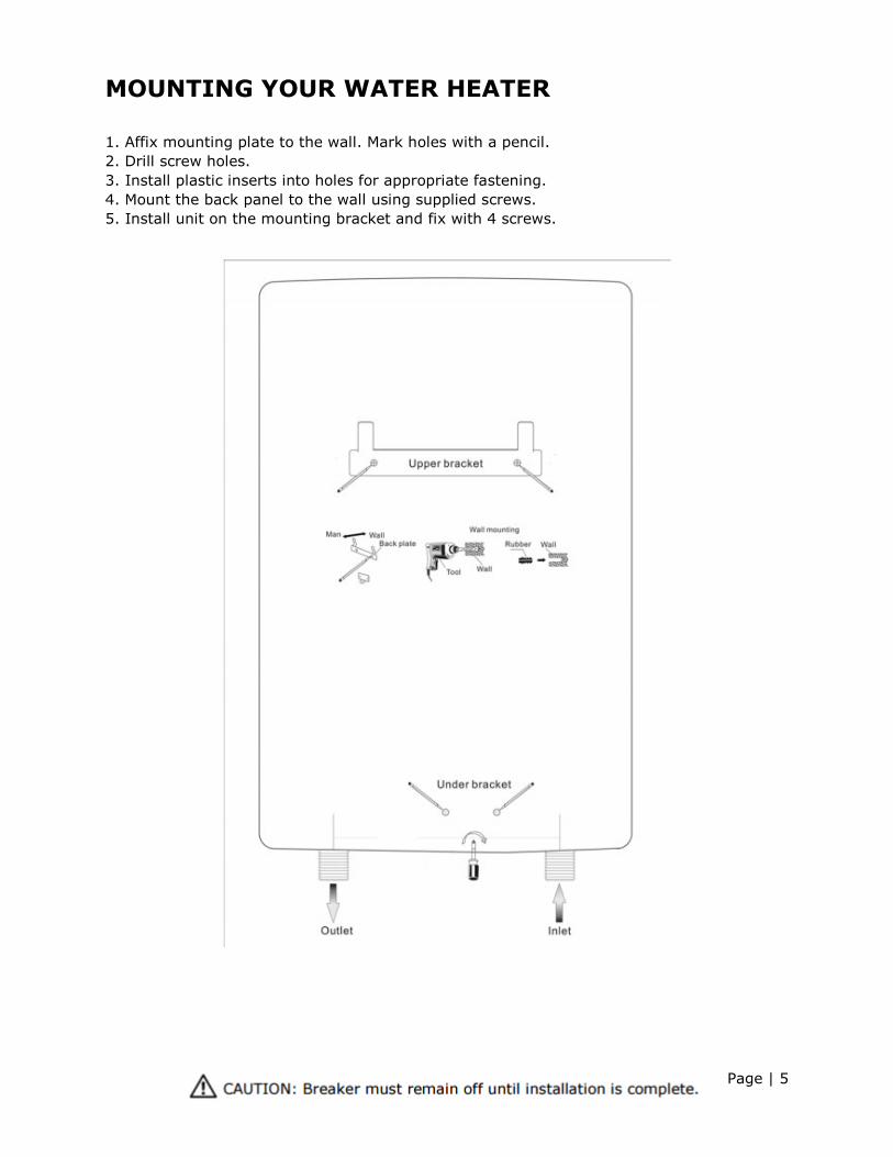
MOUNTING YOUR WATER HEATER 1. Affix mounting plate to the wall. Mark holes with a pencil. 2. Drill screw holes. 3. Install plastic inserts into holes for appropriate fastening. 4. Mount the back panel to the wall using supplied screws. 5. Install unit on the mounting bracket and fix with 4 screws.
Page | 6
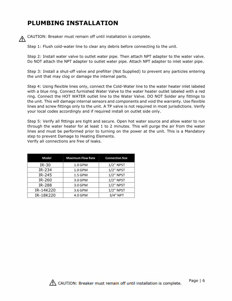
PLUMBING INSTALLATION CAUTION: Breaker must remain off until installation is complete. Step 1: Flush cold-water line to clear any debris before connecting to the unit. Step 2: Install water valve to outlet water pipe. Then attach NPT adapter to the water valve. Do NOT attach the NPT adapter to outlet water pipe. Attach NPT adapter to inlet water pipe. Step 3: Install a shut-off valve and prefilter (Not Supplied) to prevent any particles entering the unit that may clog or damage the internal parts. Step 4: Using flexible lines only, connect the Cold-Water line to the water heater inlet labeled with a blue ring. Connect furnished Water Valve to the water heater outlet labeled with a red ring. Connect the HOT WATER outlet line to the Water Valve. DO NOT Solder any fittings to the unit. This will damage internal sensors and components and void the warranty. Use flexible lines and screw fittings only to the unit. A TP valve is not required in most jurisdictions. Verify your local codes accordingly and if required install on outlet side only. Step 5: Verify all fittings are tight and secure. Open hot water source and allow water to run through the water heater for at least 1 to 2 minutes. This will purge the air from the water lines and must be performed prior to turning on the power at the unit. This is a Mandatory step to prevent Damage to Heating Elements. Verify all connections are free of leaks.
Model Maximum Flow Rate Connection Size IR-30 1.0 GPM 1/2" NPST IR-234 1.0 GPM 1/2" NPST IR-245 1.5 GPM 1/2" NPST IR-260 3.0 GPM 1/2" NPST IR-288 3.0 GPM 1/2" NPST
IR-14K220 3.6 GPM 1/2" NPST IR-18K220 4.0 GPM 3/4" NPT
Page | 7
ELECTRICAL INSTALLATION
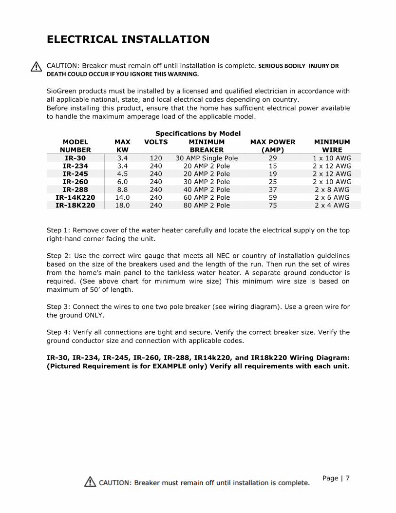
CAUTION: Breaker must remain off until installation is complete. SERIOUS BODILY INJURY OR DEATH COULD OCCUR IF YOU IGNORE THIS WARNING. SioGreen products must be installed by a licensed and qualified electrician in accordance with all applicable national, state, and local electrical codes depending on country. Before installing this product, ensure that the home has sufficient electrical power available to handle the maximum amperage load of the applicable model.
Specifications by Model MODEL
NUMBER MAX KW
VOLTS MINIMUM BREAKER
MAX POWER (AMP)
MINIMUM WIRE
IR-30 3.4 120 30 AMP Single Pole 29 1 x 10 AWG IR-234 3.4 240 20 AMP 2 Pole 15 2 x 12 AWG IR-245 4.5 240 20 AMP 2 Pole 19 2 x 12 AWG IR-260 6.0 240 30 AMP 2 Pole 25 2 x 10 AWG IR-288 8.8 240 40 AMP 2 Pole 37 2 x 8 AWG
IR-14K220 14.0 240 60 AMP 2 Pole 59 2 x 6 AWG IR-18K220 18.0 240 80 AMP 2 Pole 75 2 x 4 AWG
Step 1: Remove cover of the water heater carefully and locate the electrical supply on the top right-hand corner facing the unit. Step 2: Use the correct wire gauge that meets all NEC or country of installation guidelines based on the size of the breakers used and the length of the run. Then run the set of wires from the home’s main panel to the tankless water heater. A separate ground conductor is required. (See above chart for minimum wire size) This minimum wire size is based on maximum of 50’ of length. Step 3: Connect the wires to one two pole breaker (see wiring diagram). Use a green wire for the ground ONLY. Step 4: Verify all connections are tight and secure. Verify the correct breaker size. Verify the ground conductor size and connection with applicable codes. IR-30, IR-234, IR-245, IR-260, IR-288, IR14k220, and IR18k220 Wiring Diagram: (Pictured Requirement is for EXAMPLE only) Verify all requirements with each unit.
Page | 8
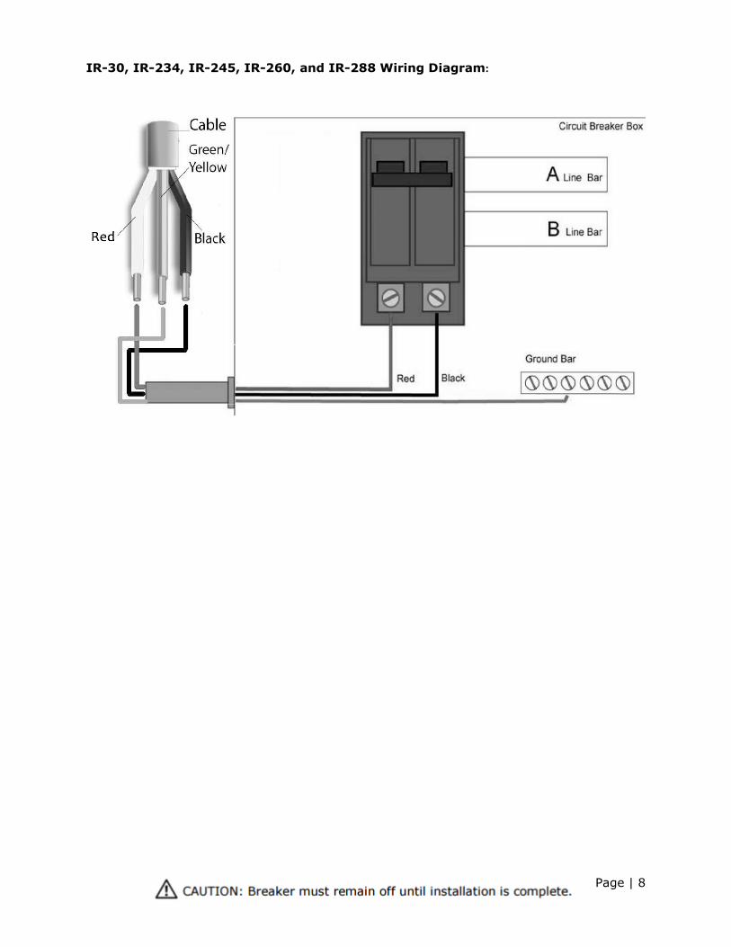
IR-30, IR-234, IR-245, IR-260, and IR-288 Wiring Diagram:
Page | 9
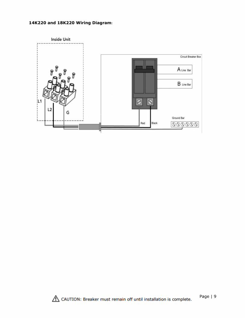
14K220 and 18K220 Wiring Diagram:
Page | 10
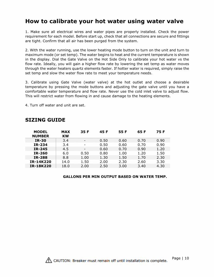
How to calibrate your hot water using water valve 1. Make sure all electrical wires and water pipes are properly installed. Check the power requirement for each model. Before start up, check that all connections are secure and fittings are tight. Confirm that all air has been purged from the system. 2. With the water running, use the lower heating mode button to turn on the unit and turn to maximum mode (or set temp). The water begins to heat and the current temperature is shown in the display. Dial the Gate Valve on the Hot Side Only to calibrate your hot water vs the flow rate. Ideally, you will gain a higher flow rate by lowering the set temp as water moves through the water heaters quartz elements faster. If hotter water is required, simply raise the set temp and slow the water flow rate to meet your temperature needs. 3. Calibrate using Gate Valve (water valve) at the hot outlet and choose a desirable temperature by pressing the mode buttons and adjusting the gate valve until you have a comfortable water temperature and flow rate. Never use the cold inlet valve to adjust flow. This will restrict water from flowing in and cause damage to the heating elements. 4. Turn off water and unit are set.
SIZING GUIDE
MODEL NUMBER
MAX KW
35 F 45 F 55 F 65 F 75 F
IR-30 3.4 - 0.50 0.60 0.70 0.90 IR-234 3.4 - 0.50 0.60 0.70 0.90 IR-245 4.5 - 0.60 0.70 0.90 1.20 IR-260 6.0 0.50 0.80 1.00 1.20 1.50 IR-288 8.8 1.00 1.30 1.50 1.70 2.30
IR-14K220 14.0 1.50 2.00 2.30 2.60 3.30 IR-18K220 18.0 2.00 2.50 3.00 3.40 4.30
GALLONS PER MIN OUTPUT BASED ON WATER TEMP.
Page | 11
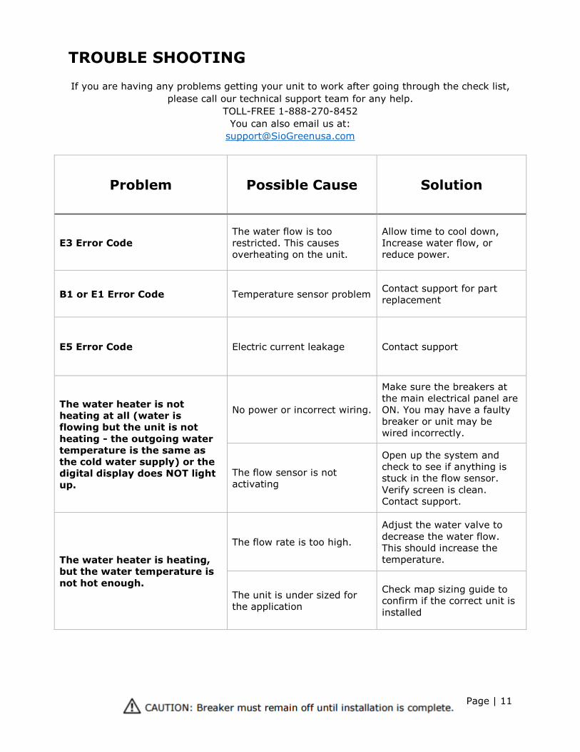
TROUBLE SHOOTING If you are having any problems getting your unit to work after going through the check list,
please call our technical support team for any help. TOLL-FREE 1-888-270-8452
You can also email us at: [email protected]
Problem Possible Cause Solution
E3 Error Code The water flow is too restricted. This causes overheating on the unit.
Allow time to cool down, Increase water flow, or reduce power.
B1 or E1 Error Code Temperature sensor problem Contact support for part replacement
E5 Error Code Electric current leakage Contact support
The water heater is not heating at all (water is flowing but the unit is not heating - the outgoing water temperature is the same as the cold water supply) or the digital display does NOT light up.
No power or incorrect wiring.
Make sure the breakers at the main electrical panel are ON. You may have a faulty breaker or unit may be wired incorrectly.
The flow sensor is not activating
Open up the system and check to see if anything is stuck in the flow sensor. Verify screen is clean. Contact support.
The water heater is heating, but the water temperature is not hot enough.
The flow rate is too high.
Adjust the water valve to decrease the water flow. This should increase the temperature.
The unit is under sized for the application
Check map sizing guide to confirm if the correct unit is installed
Page | 12
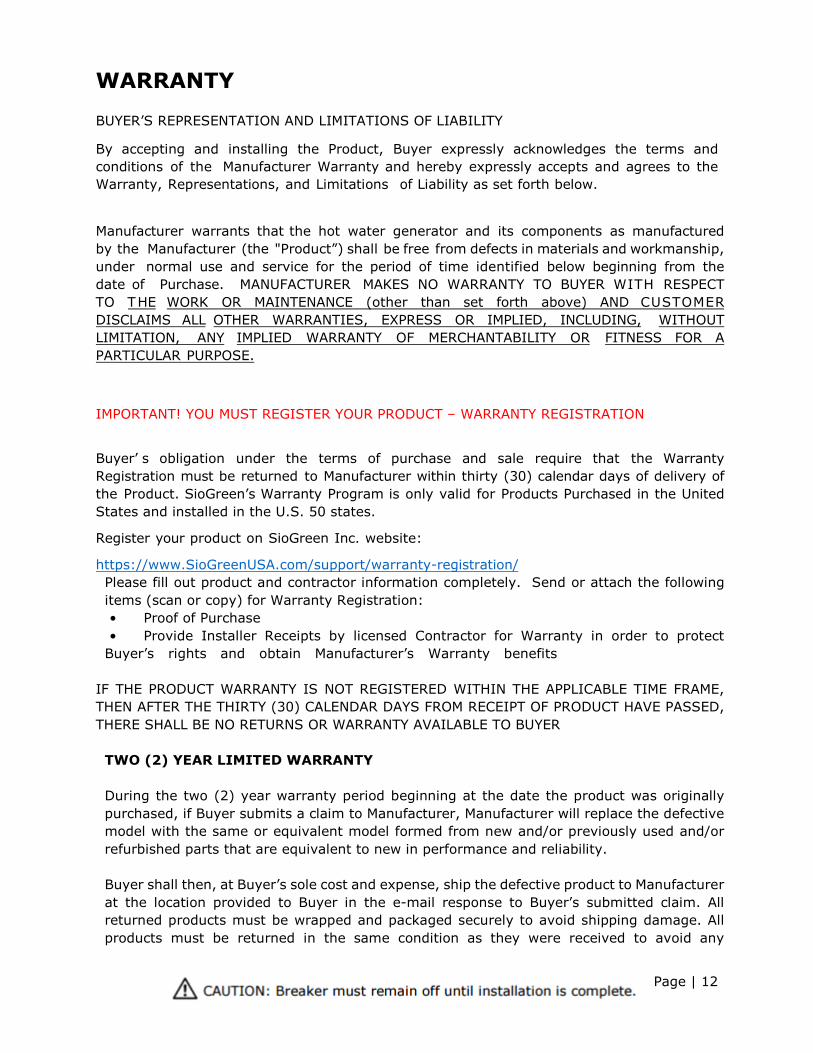
WARRANTY
BUYER’S REPRESENTATION AND LIMITATIONS OF LIABILITY
By accepting and installing the Product, Buyer expressly acknowledges the terms and conditions of the Manufacturer Warranty and hereby expressly accepts and agrees to the Warranty, Representations, and Limitations of Liability as set forth below.
Manufacturer warrants that the hot water generator and its components as manufactured by the Manufacturer (the "Product”) shall be free from defects in materials and workmanship, under normal use and service for the period of time identified below beginning from the date of Purchase. MANUFACTURER MAKES NO WARRANTY TO BUYER WITH RESPECT TO THE WORK OR MAINTENANCE (other than set forth above) AND CUSTOMER DISCLAIMS ALL OTHER WARRANTIES, EXPRESS OR IMPLIED, INCLUDING, WITHOUT LIMITATION, ANY IMPLIED WARRANTY OF MERCHANTABILITY OR FITNESS FOR A PARTICULAR PURPOSE.
IMPORTANT! YOU MUST REGISTER YOUR PRODUCT – WARRANTY REGISTRATION
Buyer’ s obligation under the terms of purchase and sale require that the Warranty Registration must be returned to Manufacturer within thirty (30) calendar days of delivery of the Product. SioGreen’s Warranty Program is only valid for Products Purchased in the United States and installed in the U.S. 50 states.
Register your product on SioGreen Inc. website:
https://www.SioGreenUSA.com/support/warranty-registration/ Please fill out product and contractor information completely. Send or attach the following items (scan or copy) for Warranty Registration: • Proof of Purchase• Provide Installer Receipts by licensed Contractor for Warranty in order to protectBuyer’s rights and obtain Manufacturer’s Warranty benefits
IF THE PRODUCT WARRANTY IS NOT REGISTERED WITHIN THE APPLICABLE TIME FRAME, THEN AFTER THE THIRTY (30) CALENDAR DAYS FROM RECEIPT OF PRODUCT HAVE PASSED, THERE SHALL BE NO RETURNS OR WARRANTY AVAILABLE TO BUYER
TWO (2) YEAR LIMITED WARRANTY
During the two (2) year warranty period beginning at the date the product was originally purchased, if Buyer submits a claim to Manufacturer, Manufacturer will replace the defective model with the same or equivalent model formed from new and/or previously used and/or refurbished parts that are equivalent to new in performance and reliability.
Buyer shall then, at Buyer’s sole cost and expense, ship the defective product to Manufacturer at the location provided to Buyer in the e-mail response to Buyer’s submitted claim. All returned products must be wrapped and packaged securely to avoid shipping damage. All products must be returned in the same condition as they were received to avoid any
Page | 13
additional costs to the Buyer. Buyer shall provide Manufacturer with a valid credit card to use for payment of Manufacturer’s shipping and handling costs and to hold on file for assurance for any additional damages to the returned unit reviewed by the Manufacturer. Once the unit has been received and inspected by Manufacturer, Manufacturer will immediately ship the same or equivalent model formed from new and/or previously used and/or refurbished parts that are equivalent to new in performance and reliability to Buyer to replace the returned model. Upon Manufacturer receiving the defective product from Buyer and Buyer receiving the replacement product from Manufacturer, the Warranty obligation set forth hereunder shall be deemed completed satisfactorily. Manufacturer reserves the right to deny warranty coverage upon Manufacturer’s examination of unit.
This WARRANTY is subject to the following:
a) This Manufacturer Warranty is only applicable to the original purchaser at the original installation address of purchaser (“Buyer”). The Warranty is personal only to the Buyer with proof of purchase and is not available to an individual who is only in possession of the Product.
b) IMPORTANT: MANUFACTURER REQUIRES BUYER TO INSTALL THIS PRODUCT USING A LICENSED CONTRACTOR. OWNER INSTALLATION OF THE PRODUCT VOIDS THE WARRANTY. Manufacturer Warranty is only offered if the Product is installed by a Licensed Contractor who installs the Product in accordance with any national and/or local codes and installed to Manufacturer Specifications using all included components supplied by Manufacturer and other parts that may be required to protect equipment. The Licensed Contractor shall comply with all laws, ordinances, and regulations, both state and federal, applicable to the Product. Buyer is solely responsible for being compliant with such laws and expressly warrants to Manufacturer that the Product will be installed according to such rules and regulations. Buyer assumes all such risk associated with being compliant with these laws. Buyer agrees to expressly relieve Manufacturer, its agents or employees from any all liability by reason of any action, injury, loss, or damage to any person or property resulting from any lack of compliance on behalf of Buyer, irrespective of the cause of such injury, loss, or damage. Should Buyer not be compliant, Buyer shall have no warranty rights.
c) WARRANTY DOES NOT COVER:
• Product misuse, tampering, or misapplication, accidental damage, or improper installation
• Product failure caused by chemical corrosion, or freezing.
• Product failure due to lightning, flood, or other natural or manmade calamities
• Costs incurred for shipping, delivery, handling, and/or administrative charges
• Labor charges of any kind
Page | 14
BUYER’S REPRESENTATIONS
a) Buyer warrants acknowledges and agrees that it shall not use the Product other than for the purposes it is intended for. Buyer further warrants that Buyer shall only use the Product in accordance with the Manufacturer’s recommended guidelines as set forth in this Manual. Buyer expressly waives all liability and indemnifies and holds Manufacturer harmless for any action against Manufacturer for any deviation by Buyer from the intended purposes of the Product.
b) Buyer warrants acknowledges and agrees that Buyer shall not reverse-engineer, modify or create a derivative work of the Product without prior written permission of Manufacturer
c) Buyer has no right to modify or alter the Product and shall not make any improvements, alterations or modifications to the Product. If Buyer modifies, alters or improves the Product, the Warranty shall be and is hereby voided
d) In the event that the Product is not installed or used in accordance with the Manufacturer’s specifications as set forth in this manual, any and all warranties either expressed or implied shall be and are hereby voided. Only upon proper installation and use of the Product shall the above warranty apply. Any tampering, misuse or negligence in handling or use of Product shall render the warranty void. Further, any warranty is void if, at any time, Buyer attempts to make any changes to any of the components of the Product.
LIMITATIONS OF LIABILITY
a) Risk of Loss. Buyer agrees to assume all risk of loss or damage, no matter how occasioned.
b) Indemnification. The Buyer agrees to indemnify, hold harmless, save and defend Manufacturer and its agents or employees from and against any and all claims, liens, liability, loss or damage, including expenses and attorney's fees, arising out of or in connection with, directly or indirectly, the Product, including claims, liens, liability, loss or damage to any employee, family member, agent or representative of the Buyer. This shall include claims, liens, liability, loss or damage caused by any actual or claimed negligence or gross negligence (active or passive), of Manufacturer and its contractors, agents or employees, either as the sole or contributing cause, whether for damage to property, wherever situated, or bodily or personal injury, including death, resulting from or sustained by any person or persons at any time.
c) Waiver of Liability. The Client agrees to expressly relieve Manufacturer, its contractors, agents or employees from any and all liability by reason of any injury,
Page | 15
loss or damage to any person or property resulting from the installation of the Product, irrespective of the of the cause of such injury, loss or damage.
d) The manufacturer shall not be liable for any water damage arising, directly or indirectly, from any defect in the hot water heater component part(s) or from its use.
e) IN NO EVENT SHALL MANUFACTURER BE LIABLE FOR ANY SPECIAL, INDIRECT, INCIDENTIAL, OR CONSEQUENTIAL DAMAGES OR FOR LOST INCOME, LOSS OF PROFITS, SAVINGS OR OTHER ECONOMIC LOSS ARISING OUT OF OR CONNECTED WITH THIS PRODUCT, REGARDLESS OF WHETHER A CLAIM IS BASED ON CONTRACT, TORT, STRICT LIABILITY OR OTHERWISE.
f) NOTWITHSTANDING ANYTHING TO THE CONTRARY CONTAINED IN THIS MANUAL, THE LIABILITY FOR DAMAGES FROM ANY AND ALL CAUSES WHATSOEVER AND REGARDLESS OF THE FORM OF ACTION, WHETHER IN CONTRACT, TORT OR NEGLIGENCE, SHALL NOT EXCEED THE AMOUNT OF THE PRODUCT PRICE
Choice of Law.
The laws and statutes of the State of Florida shall govern the construction, interpretation, and performance of this Manual and Warranty. Any conflict in law shall be resolved in favor of the laws and statutes of the State of Florida. The venue for any dispute shall lie in Pinellas County, Florida.
Manufacturer Contact:
SioGreen Inc.
4501 107th Circle N. Suite #1
Clearwater, FL 33762
888-270-8452
www.SioGreenUSA.com
Customer Support: [email protected]
Manufacturer reserves the right to discontinue or change at any time, specifications or designs without notice and without incurring an obligation.