Embed Size (px)
Citation preview
Product SinuCom 1
Installation 2
General Operating Sequences 3
SinuCom NC: Functions 4
SinuCom FFS: Functions 5
SinuCom CFS: Functions 6
SinuCom ARC : Functions 7
SinuCom PCIN: Functions 8
Appendix A
Index I
SINUMERIK 840D sl/840Di sl/ 840D/840Di/810D
SinuCom Installation/Service Tools
Operating Manual
07/2008
Valid for Control
SINUMERIK 840D sl/ 840DE sl SINUMERIK 840Di sl/ 840DiE sl
SINUMERIK 840D/840Di/810D
Software Version
SinuCom 7.50
SINUMERIK®-Documentation
Registered trademarks All names with the protective right label ® are registered trademarks of the Siemens AG. The other product and system names in this document may be registered trademarks of their respective companies and must be treated accordingly. Disclaimer of liability We have checked that the contents of this document correspond to the hardware and software described. Nonetheless, differences might exist and therefore we cannot guarantee that they are completely identical. The information contained in this document is, however, reviewed regularly and any necessary changes will be included in the next edition.
Printing history Brief details of this edition and previous editions are listed below. The status of each edition is shown by the code in the "Remarks" columns. Status code in the "Remarks" column: A .... New documentation. B .... Unrevised reprint with new Order No. C .... Revised edition with new status. Edition Order No. Remarks 06.03 Included in online help only - A 03/2007 Included in online help only - C 07/2008 included in online help only - C
© Siemens AG 2008. All Rights Reserved. Bestell-Nr. included in online help only -
Siemens-Aktiengesellschaft.
07/2008 Preface
© Siemens AG 2008 All Rights Reserved SINUMERIK 840D sl/840Di sl/ 840D/840Di/810D SinuCom (INC) - 07/2008 iii
Preface
Structure of the documentation SINUMERIK documentation is organized in 3 parts: • General documentation • User documentation • Manufacturer/Service Documentation An overview of publications (updated monthly) indicating the language versions available can be found on the Internet at: http://www.siemens.com/motioncontrol Follow menu items "Support" → "Technical Documentation" → "Ordering Documentation" →"Printed Documentation". The Internet version of the DOConCD (DOConWEB) is available at: http://www.automation.siemens.com/doconweb Information about training courses and FAQs (Frequently Asked Questions) can be found at the following web site: http://www.siemens.com/motioncontrol under menu option "Support"
Reader group This manual is intended for users of machine tools with SINUMERIK 840D sl/ 840Di sl and SINAMICS drive, SINUMERIK 840D/ 840Di/ 810D and SIMODRIVE.
Standard version This Parameter Manual only describes the functionality of the standard version. Extensions or changes made by the machine tool manufacturer are documented by the machine tool manufacturer. Other functions not described in this documentation might be executable in the control. This does not, however, represent an obligation to supply such functions with a new control or when servicing. Further, for the sake of simplicity, this documentation does not contain all detailed information about all types of the product and cannot cover every conceivable case of installation, operation or maintenance.
Preface 07/2008
© Siemens AG 2008 All Rights Reserved iv SINUMERIK 840D sl/840Di sl/ 840D/840Di/810D SinuCom (INC) - 07/2008
Technical Support If you have any questions, please get in touch with our Hotline: Europe / Africa
Phone +49 180 5050 - 222
Fax +49 180 5050 - 223
Internet http://www.siemens.de/automation/support-request
America
Phone +1 423 262 2522
Fax +1 423 262 2200
E-mail mailto:[email protected]
Asia / Australia
Phone +86 1064 719 990
Fax +86 1064 747 474
E-mail mailto:[email protected]
Note
Country telephone numbers for technical support are provided under the following Internet address: http://www.siemens.com/automation/service&support Calls are subject to charge, e.g. € 0.14/min on the German landline network. Tariffs of other hone providers may differ.
Questions about the documentation If you have any queries (suggestions, corrections) in relation to this documentation, please fax or e-mail us: Fax +49 9131 98 - 2176
E-mail mailto:[email protected]
Fax form: See the reply form at the end of the document.
SINUMERIK Internet address http://www.siemens.com/sinumerik
07/2008 Preface
© Siemens AG 2008 All Rights Reserved SINUMERIK 840D sl/840Di sl/ 840D/840Di/810D SinuCom (INC) - 07/2008 v
Aim This document explains how to install the SINUMERIK SinuCom Installation/Service Tools and describes its functionality. The purpose of the SinuCom Installation/Service Tools is to facilitate start-up and installation of the SINUMERIK 840D sl/ 804Di sl/ 840D/ 840Di/ 810D. On the SINUMERIK 840D/810D the tool is started from the PG/PC in online mode (PG/PC control via OPI). It is included in the Software on the SINUMERIK 840Di.
Standard scope This publication describes the standard scope of functions. Any extensions or modifications to the standard scope made by the machine manufacturer will be documented by the machine manufacturer. Please contact your local Siemens sales office for further information about other publications relating to SINUMERIK 840D/840Di/810D and publications that are applicable to all SINUMERIK controls (e.g. universal interface, measuring cycles ...). Other functions not described in this documentation might be executable in the control. This does not, however, represent an obligation to supply such functions with a new control or when servicing.
! Important
This System Description is applicable to the following control types: SINUMERIK 840D sl / SINUMERIK 840DE sl (export version) SINUMERIK 840D powerline / 840DE powerline (export version) SINUMERIK 840Di powerline / 840DiE powerline (export version) SINUMERIK 810D powerline / 810DE powerline (export version) with operator panel types OP 010, OP 010C, OP 010S, OP 12 or OP 15 (PCU 50, PCU 70/ NCU 710, NCU 720, NCU 730).
Notes The following notes with special significance are used in the documentation:
Note
This symbol always appears in this documentation to draw your attention to further information relevant to the subject in hand.
! Important
This symbol always appears in the documentation when important information is being conveyed.
Preface 07/2008
© Siemens AG 2008 All Rights Reserved vi SINUMERIK 840D sl/840Di sl/ 840D/840Di/810D SinuCom (INC) - 07/2008
Additional ordering options
Appears in the documentation whenever a described function is not contained in the standard version but may be ordered as an option.
Safety information This manual contains notices that you should observe to ensure your own personal safety, as well as to protect the product and connected equipment. Notices referring to your personal safety are highlighted in the manual by a safety alert symbol; notices referring to property damage only have no safety alert symbol. The warnings are shown below in decreasing order of danger.
! Danger
Indicates an imminently hazardous situation which, if not avoided, will result in death or serious injury or in substantial property damage.
! Warning
Indicates a potentially hazardous situation which, if not avoided, could result in death or serious injury or in substantial property damage.
! Caution
Used with the safety alert symbol indicates a potentially hazardous situation which, if not avoided, may result in minor or moderate injury or in property damage.
Caution
Used without safety alert symbol indicates a potentially hazardous situation which, if not avoided, may result in property damage.
Notice
Used without the safety alert symbol indicates a potential situation which, if not avoided, may result in an undesirable result or state.
If several hazards of different degrees occur, the hazard with the highest degree must always be given priority. If a warning note with a warning triangle warns of personal injury, the same warning note can also contain a warning of material damage.
07/2008 Preface
© Siemens AG 2008 All Rights Reserved SINUMERIK 840D sl/840Di sl/ 840D/840Di/810D SinuCom (INC) - 07/2008 vii
Qualified personnel Start-up and operation of the device/equipment/system in question must only be performed using this documentation. The device/system must only be started and operated by qualified personnel. Qualified personnel as referred to in the safety guidelines in this documentation are those who are authorized to start up, earth and label units, systems and circuits in accordance with the relevant safety standards.
Correct usage Note the following:
! Warning
The unit may be used only for the applications described in the catalog or the technical description, and only in combination with the equipment, components and devices of other manufacturers where recommended or permitted by Siemens. This product can only function correctly and safely if it is transported, stored, set up, and installed correctly, and operated and maintained as recommended.

Preface 07/2008
© Siemens AG 2008 All Rights Reserved viii SINUMERIK 840D sl/840Di sl/ 840D/840Di/810D SinuCom (INC) - 07/2008
07/2008 Contents
© Siemens AG 2008 All Rights Reserved SINUMERIK 840D sl/840Di sl/ 840D/840Di/810D SinuCom (INC) - 07/2008 ix
Contents
1 Product SinuCom............................................................................ 1-13
1.1 Product features............................................................................ 1-14
1.2 Scope of supply ............................................................................ 1-16
1.3 Permissible PC platforms ............................................................. 1-17
2 Installation ....................................................................................... 2-19
2.1 Installation variants ....................................................................... 2-20
2.2 Installation of SinuCom NC........................................................... 2-20
2.3 Installation of SinuCom FFS......................................................... 2-22
2.4 Installation of SinuCom CFS......................................................... 2-23
2.5 Installation of SinuCom ARC ........................................................ 2-24
2.6 Installation of SinuCom PCIN ....................................................... 2-25
2.7 Uninstalling ................................................................................... 2-26
3 General Operating Sequences ...................................................... 3-27
3.1 Installation and start-up with SinuCom NC................................... 3-28
3.2 Help functions ............................................................................... 3-29
3.3 Using the keyboard....................................................................... 3-32
4 SinuCom NC: Functions ................................................................ 4-33
4.1 Document Scope and Supported Systems................................... 4-34 4.1.1 Scope of this Manual ................................................................. 4-34 4.1.2 Supported Systems and NCK Versions .................................... 4-34 4.1.3 Supported Languages ............................................................... 4-34
4.2 What's New in SinuCom NC 7.50................................................. 4-35
4.3 Main Menu .................................................................................... 4-35
4.4 Toolbar Buttons............................................................................. 4-36
4.5 Alarm Messages ........................................................................... 4-36
4.6 Machine Data ("MD") .................................................................... 4-37
Contents 07/2008
© Siemens AG 2008 All Rights Reserved x SINUMERIK 840D sl/840Di sl/ 840D/840Di/810D SinuCom (INC) - 07/2008
4.6.1 Viewing and Configuring MD..................................................... 4-37 4.6.2 Machine Data Project Tree........................................................ 4-39 4.6.3 Service Data .............................................................................. 4-41
4.7 Archiving ....................................................................................... 4-42
4.8 SinuCom NC Trace....................................................................... 4-43 4.8.1 Overview: How Trace is Used ................................................... 4-44 4.8.2 Sessions and Their Content ...................................................... 4-49 4.8.3 Reference Waveforms............................................................... 4-52 4.8.4 Toolbars and Menus.................................................................. 4-54 4.8.5 Context Menus .......................................................................... 4-68 4.8.6 Dialogs....................................................................................... 4-73 4.8.7 Trace Symbol Import Wizard (TSIW) ........................................ 4-88 4.8.8 Trace Setup Wizard (TSW) ....................................................... 4-94
4.9 Safety Integrated Acceptance Test Wizard .................................. 4-99 4.9.1 Example:.................................................................................... 4-99 4.9.2 Common Screen Contents ........................................................ 4-101 4.9.3 Custom Templates .................................................................... 4-104
5 SinuCom FFS: Functions............................................................... 5-109
5.1 Operation ...................................................................................... 5-110
5.2 Display of the NC image ............................................................... 5-110
5.3 Displaying/editing the FFS image................................................. 5-110
5.4 Writing/Reading an NC image to NC card.................................... 5-111
6 SinuCom CFS: Functions .............................................................. 6-113
6.1 Operation ...................................................................................... 6-114 6.1.1 Create projekt ............................................................................ 6-114 6.1.2 Set up project views................................................................... 6-116 6.1.3 Generate image ......................................................................... 6-117 6.1.4 Read in / out image on the CompactFlash Card ....................... 6-117 6.1.5 Select language ......................................................................... 6-118
7 SinuCom ARC: Functions.............................................................. 7-119
7.1 Operation ...................................................................................... 7-120
7.2 Displaying the contents of the archive.......................................... 7-120
7.3 Editing the archive contents.......................................................... 7-120
7.4 Creating an archive....................................................................... 7-122
8 SinuCom PCIN: Functions ............................................................. 8-123
8.1 Operation ...................................................................................... 8-124
07/2008 Contents
© Siemens AG 2008 All Rights Reserved SINUMERIK 840D sl/840Di sl/ 840D/840Di/810D SinuCom (INC) - 07/2008 xi
8.2 Functions ...................................................................................... 8-124
8.3 File WINPCIN.ini ........................................................................... 8-125
A Appendix ......................................................................................... A-127
A.1 Abbreviations................................................................................ A-127 A.2 Definitions..................................................................................... A-129
I Index.................................................................................................. I-135

Contents 07/2008
© Siemens AG 2008 All Rights Reserved xii SINUMERIK 840D sl/840Di sl/ 840D/840Di/810D SinuCom (INC) - 07/2008
07/2008 1 Product SinuCom 1.1 Product features
© Siemens AG 2008 All Rights Reserved SINUMERIK 840D sl/840Di sl/ 840D/840Di/810D SinuCom (INC) - 07/2008 1-13
1 Product SinuCom
1.1 Product features............................................................................ 1-14
1.2 Scope of supply ............................................................................ 1-16
1.3 Permissible PC platforms ............................................................. 1-17
1
1 Product SinuCom 07/2008 1.1 Product features
© Siemens AG 2008 All Rights Reserved 1-14 SINUMERIK 840D sl/840Di sl/ 840D/840Di/810D SinuCom (INC) - 07/2008
1.1 Product features This program package supports simple and effective startup of SINUMERIK 840D sl/ 840Di sl and SINUMERIK 810D/ 840D/ 840Di controls on CNC machines. On the SINUMERIK 810D/ 840D/ 840D sl the tool is started from the PG/PC in online mode (PG/PC control via the OPI interface), in the case of the SINUMERIK 840Di/ 840Di sl it is included in the software.
Product components The installation/service tools SinuCom comprises five tools: 1. SinuCom NC
− SinuCom NC Trace − SinuCom NC SI
2. SinuCom FFS 3. SinuCom CFS 4. SinuCom ARC 5. SinuCom PCIN
Functions The installation/service tools tool SinuCom offers the following functions:
• Use of the Trace functionality • Safety Integrated Acceptance Test Wizard • Creation of CompactFlash Card images • Series commissioning file management • Transfer of CNC user data
Note
The NC card is programmed with standard tools (e. g. Cardware) that are not contained in the included in the scope of supply of SinuCom FFS.
A Flash File System (FFS) is comparable with a DOS data medium, e.g. a diskette. Before data can be archived, the system must be formatted. Then the directory structures can be created and files stored in a suitable format. The data medium is an electrically erasable PROM (EEPROM). This means that before writing the relevant sector must be erased. Algorithms written for the module identification are required for erasing and writing. They largely determine the speed with which data are written. An FFS system can be read directly from DOS/WINDOWS. Because the NC system software also stored on the NC card does not exist in FFS format, this can only be performed with “SINUCOPY-FFS”.
Note
Please read the A&D software marketing guidelines before duplicating software.
07/2008 1 Product SinuCom 1.1 Product features
© Siemens AG 2008 All Rights Reserved SINUMERIK 840D sl/840Di sl/ 840D/840Di/810D SinuCom (INC) - 07/2008 1-15
SinuCom NC Trace SinuCom NC Trace function is used for the dynamic recording of CNC, PLC and HMI variables, and of drive signals that are available via the CNC. These variables can be displayed, printed out or stored in a file, similar to using an oscillograph or logic analyzer. The SinuCom NC Trace function provides support in:
• Fault detection and fault correction • Machine performance analysis, benchmarking and tuning • Process performance analysis, benchmarking and tuning
SinuCom NC SI SinuCom NC SI integrated acceptance test, it supports the original equipment manufacturer (OEM), and optimizes the process:
• Verification of machines in accordance with EU Machinery Directive EN 954-1 (control category 3)
• Testing of safety functions (partly automated) during the machine acceptance
• Logging of measured data and test results incl. Trace function records • Testing of single/special-purpose machines, machine components (as a
partial test) and series machines as series startup • Shorter startup times since, in the new acceptance mode, power-on alarms
during the acceptance test are acknowledged by RESET • User-friendly operation due to controlled execution and the automatic
configuration of the Trace functions. • Unambiguous quality verification for original equipment manufacturers as
well as customers and for dealings with government agencies.
SinuCom FFS SinuCom FFS is used to generate an image for the PC card of the CCU/NCU of SINUMERIK 810D/840D (powerline). It contains:
• Processing of the flash file system • Preparing the image for programming the PC card • Integrated help
1 Product SinuCom 07/2008 1.2 Scope of supply
© Siemens AG 2008 All Rights Reserved 1-16 SINUMERIK 840D sl/840Di sl/ 840D/840Di/810D SinuCom (INC) - 07/2008
SinuCom CFS SinuCom CFS is used to generate an image for the SINUMERIK 840D sl NCU’s CF card, in Ext3 format. It contains:
• Preparing the image for programming the CF card • Integrated help
SinuCom ARC SinuCom ARC simplifies the processing of series startup files:
• Reading, deleting, inserting and changing series startup files • Integrated help
SinuCom PCIN The SinuCom PCIN program is used to send and receive CNC user data, such as machine data and part programs, via the serial interface between a Siemens PC/PG and a Siemens control. It contains:
• Setting up and interrogating V.24 interface • Editing archive files • Storing files from directories individually • Secure data transmission • Integrated help
The service tool SinuCom PCIN can be operated with the mouse or keyboard.
1.2 Scope of supply
Supply medium The installation/service tools SinuCom is supplied on DVD.
Licenses The following licenses are available: • Single license • Single license without data medium • Software Update Service • Update for certain SW version
Foreign languages The installation/service tools SinuCom is supplied in six languages (English/German/French/Spanish/Italian/Chinese, ATW Certificate Exportlist, Service Data only). Language switchover only takes effect after rebooting.
07/2008 1 Product SinuCom 1.3 Permissible PC platforms
© Siemens AG 2008 All Rights Reserved SINUMERIK 840D sl/840Di sl/ 840D/840Di/810D SinuCom (INC) - 07/2008 1-17
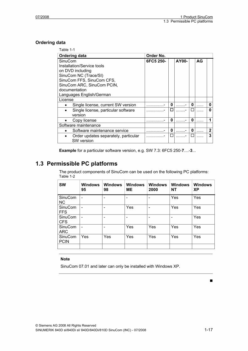
Ordering data Table 1-1 Ordering data Order No. SinuCom Installation/Service tools on DVD including SinuCom NC (Trace/SI) SinuCom FFS, SinuCom CFS, SinuCom ARC, SinuCom PCIN, documentation Languages English/German
6FC5 250- AY00- AG
License • Single license, current SW version ...............- 0 ........- 0 ...... 0• Single license, particular software
version ...............- ........- ...... 0
• Copy license ...............- 0 ........- 0 ...... 1Software maintenance
• Software maintenance service ...............- 0 ........- 0 ...... 2• Order updates separately, particular
SW version ...............- ........- ...... 3
Example for a particular software version, e.g. SW 7.3: 6FC5 250-7....-3...
1.3 Permissible PC platforms The product components of SinuCom can be used on the following PC platforms: Table 1-2
SW Windows 95
Windows 98
Windows ME
Windows 2000
Windows NT
Windows XP
SinuCom NC
- - - - Yes Yes
SinuCom FFS
- - Yes - Yes Yes
SinuCom CFS
- - - - - Yes
SinuCom ARC
- - Yes Yes Yes Yes
SinuCom PCIN
Yes Yes Yes Yes Yes Yes
Note
SinuCom 07.01 and later can only be installed with Windows XP.
1 Product SinuCom 07/2008 1.3 Permissible PC platforms
© Siemens AG 2008 All Rights Reserved 1-18 SINUMERIK 840D sl/840Di sl/ 840D/840Di/810D SinuCom (INC) - 07/2008
07/2008 2 Installation 2.1 Installation variants
© Siemens AG 2008 All Rights Reserved SINUMERIK 840D sl/840Di sl/ 840D/840Di/810D SinuCom (INC) - 07/2008 2-19
2 Installation
2.1 Installation variants ....................................................................... 2-20
2.2 Installation of SinuCom NC........................................................... 2-20
2.3 Installation of SinuCom FFS......................................................... 2-22
2.4 Installation of SinuCom CFS......................................................... 2-23
2.5 Installation of SinuCom ARC ........................................................ 2-24
2.6 Installation of SinuCom PCIN ....................................................... 2-25
2.7 Uninstalling ................................................................................... 2-26
2
2 Installation 07/2008 2.1 Installation variants
© Siemens AG 2008 All Rights Reserved 2-20 SINUMERIK 840D sl/840Di sl/ 840D/840Di/810D SinuCom (INC) - 07/2008
2.1 Installation variants The installation/service tools SinuCom includes four different installation variants: 1. SinuCom NC only 2. SinuCom FFS only 3. SinuCom CFS only 4. SinuCom ARC only 5. SinuCom PCIN only
2.2 Installation of SinuCom NC
Requirements SinuCom NCrequires Windows® XP professional (SP1 or SP2). SinuCom NC occupies approximately 7 MB in the Windows® system directory and approximately 52 MB in the SinuCom NC directory. If HMI Advanced is not already installed, an additional 156 MB are required. The program is included in the scope of delivery of the SINUMERIK 840Di sl.
Procedure 1. Insert the DVD into the drive of your PG/PC 2. Start Windows Explorer (or MS-DOS). 3. Change to the CD/DVD-drive. 4. Open the folder "SinuCom NC”. 5. Start the program "Setup.exe”. This program starts up an operator-guided
installation of SinuCom NC. 6. A warm start must be performed on the PG/PC after the installation. The info files "siemensd.txt" (German) and "siemense.txt" (English) are copied into the SinuCom NC directory on your hard disk by the SETUP program, so this information is still available to you after installation.
Starting SinuCom NC "SinuCom NC" is started as follows:
1. Double-click the "SinuComNC" icon. 2. Via the Windows task bar of the PG/PC: "Start" → "Programs" →
"SinuCom" → "SinuComNC".
07/2008 2 Installation 2.2 Installation of SinuCom NC
© Siemens AG 2008 All Rights Reserved SINUMERIK 840D sl/840Di sl/ 840D/840Di/810D SinuCom (INC) - 07/2008 2-21
Note
On 840Di, the 840Di software is usually installed before the optional HMI Advanced software. In this case, SinuCom NC will not automatically be installed on softkey 9. To make this softkey operational, SinuCom NC must be reinstalled after the complete installation of the 840Di software.
Note
SinuCom NC can be run without a mouse by using a keyboard.
Establishing a connection to the NC Starting with SinuCom NC, the "NCU Connection Wizard" (NCW) is the preferred tool for connecting the NCK, PLC, and drives.
Starting NCU Connection Wizard • Via the Windows taskbar of the PG/PC: "Start" → "Programs" → "SinuCom"
→ "NC Connect Wizard". • If SinuCom NC is unable to connect at startup, a message automatically
appears that provides the NCW as a selection. The wizard makes a selection of MPI or Ethernet connections available, based on the answers to a few questions. Changes made using the NC Connection Wizard (NCW) become effective only after SinuCom NC has been restarted. For SINUMERIK powerline systems, a number of drivers are provided; however, if the driver appropriate to your MPI hardware does not appear, you may have to obtain and install the driver separately (e. g., from SIMATIC Software). SINUMERIK solution line uses an Ethernet connection that requires no drivers.
2 Installation 07/2008 2.3 Installation of SinuCom FFS
© Siemens AG 2008 All Rights Reserved 2-22 SINUMERIK 840D sl/840Di sl/ 840D/840Di/810D SinuCom (INC) - 07/2008
2.3 Installation of SinuCom FFS
Requirements • SinuCom FFS runs under Windows Me/NT 4.0/XP. • SINUMERIK 810D/840D powerline. • SinuCom FFS requires approx. 1.2 MB. • Before you can install SinuCom FFS you must first close down all other
applications (not the Explorer). When copying the software, be sure to follow the A&D software marketing guidelines!
Procedure 1. Insert the DVD into the drive of your PG/PC 2. Start Windows Explorer (or MS-DOS). 3. Change to the CD/DVD-drive. 4. Open the folder "SinuCom FFS”. 5. Start the program "Setup.exe”. This program starts up an operator-guided
installation of SinuCom FFS. 6. A warm start must be performed on the PG/PC after the installation.
The info files "siemensd.txt" (German) and "siemense.txt" (English) are copied into the SinuCom NC directory on your hard disk by the SETUP program, so this information is still available to you after installation.
Note
• You can choose any drive name for the OMNI97 device: Enter the drive letter in menu "Control Panel/Device Manager/Drives/OMNI97".
• Windows NT: Enter the drive letter in menu "OmniControl/DriveLetter".
Starting SinuCom FFS "SinuCom FFS” is started as follows: • Double-click the "SinuCom FFS" icon • Via the Windows task bar of the PG/PC: "Start” → "Programs" → "SinuCom" →
"SinuComFFS"
07/2008 2 Installation 2.4 Installation of SinuCom CFS
© Siemens AG 2008 All Rights Reserved SINUMERIK 840D sl/840Di sl/ 840D/840Di/810D SinuCom (INC) - 07/2008 2-23
2.4 Installation of SinuCom CFS
Requirements • SinuCom CFS requires the Windows XP software platform. • 156 MB memory space is required to install the SINUMERIK 840D sl system
software. • SinuCom CFS occupies approx. 1 MB memory space. • Terminate all applications (except the Explorer) before installing SinuCom CFS.
Procedure 1. Insert the DVD into the drive of your PG/PC. 2. Start Windows Explorer (or MS-DOS). 3. Change to the CD/DVD-drive. 4. Open the folder "SinuCom CFS”. 5. Start the program "Setup.exe”. This program starts up an operator-guided
installation of SinuCom CFS. 6. A warm start must be performed on the PG/PC after the installation.
The info files "siemensd.txt" (German) and "siemense.txt" (English) are copied into the SinuCom NC directory on your hard disk by the SETUP program, so this information is still available to you after installation.
Starting SinuCom CFS "SinuCom CFS” is started as follows: • Double-click the "SinuCom CFS" icon • Via the Windows task bar of the PG/PC: "Start” → "Programs" → "SinuCom" →
"SinuComCFS"
2 Installation 07/2008 2.5 Installation of SinuCom ARC
© Siemens AG 2008 All Rights Reserved 2-24 SINUMERIK 840D sl/840Di sl/ 840D/840Di/810D SinuCom (INC) - 07/2008
2.5 Installation of SinuCom ARC
Requirements • SinuCom ARC runs under Windows ME, Windows NT 4.0, Service Pack 6, and
higher), WindowsXP or Windows 2000. • SinuCom ARC requires approx. 0.7 MB. • Before you can install SinuCom ARC you must first close down all other
applications (not the Explorer).
Procedure 1. Insert the DVD into the drive of your PG/PC 2. Start Windows Explorer (or MS-DOS). 3. Change to the CD/DVD-drive. 4. Open the folder "SinuCom ARC”. 5. Start the program "Setup.exe”. This program starts up an operator-guided
installation of SinuCom ARC. 6. A warm start must be performed on the PG/PC after the installation.
The info files "siemensd.txt" (German) and "siemense.txt" (English) are copied into the SinuCom ARC directory on your hard disk by the SETUP program. So this information is still available to you after installation.
Starting SinuCom ARC SinuCom ARC is started as follows:
1. Double-click the "SinuCom ARC" icon. 2. Via the Windows task bar of the PG/PC: "Start" → "Programs" → "SinuCom"
→ "SinuComARC". 3. In the "SinuCom NC" program via the menu "Options" → "SinuComARC".
07/2008 2 Installation 2.6 Installation of SinuCom PCIN
© Siemens AG 2008 All Rights Reserved SINUMERIK 840D sl/840Di sl/ 840D/840Di/810D SinuCom (INC) - 07/2008 2-25
2.6 Installation of SinuCom PCIN
Requirements • SinuCom PCIN runs under Windows 95/ 98/ ME/ NT 4.0/ 2000/ XP. • SinuCom PCIN requires approx. 1.2 MB. • HMI-Advanced SW 6.1.05. • Before you can install SinuCom PCIN you must first close down all other
applications (not the Explorer).
Procedure 1. Insert the DVD into the drive of your PG/PC 2. Start Windows Explorer (or MS-DOS). 3. Change to the CD/DVD-drive. 4. Open the folder "SinuCom PCIN”. 5. Start the program "Setup.exe”. This program starts up an operator-guided
installation of SinuCom PCIN. 6. A warm start must be performed on the PG/PC after the installation.
The info files "siemensd.txt" (German) and "siemense.txt" (English) are copied into the SinuCom PCIN directory on your hard disk by the SETUP program. So this information is still available to you after installation.
Starting SinuCom PCIN "SinuCom PCIN” is started as follows: • Double-click the "SinuCom PCIN" icon. • Via the Windows task bar of the PG/PC: "Start" → "Programs" → "SinuCom" →
"SinuCom PCIN".
2 Installation 07/2008 2.7 Uninstalling
© Siemens AG 2008 All Rights Reserved 2-26 SINUMERIK 840D sl/840Di sl/ 840D/840Di/810D SinuCom (INC) - 07/2008
2.7 Uninstalling
Requirements Before you can uninstall SinuCom, you must first close down all other applications (not the Explorer).
Procedure 1. Via the Windows task bar of the PG/PC: "Start" → "Settings" → "System
Control" → "Software". All programs installed are displayed in the "Software" window.
2. Select the program to be deleted and click the "Remove" button. 3. The SinuCom commissioning / service tools are removed after the warm start.
07/2008 3 General Operating Sequences 3.1 Installation and start-up with SinuCom NC
© Siemens AG 2008 All Rights Reserved SINUMERIK 840D sl/840Di sl/ 840D/840Di/810D SinuCom (INC) - 07/2008 3-27
3 General Operating Sequences
3.1 Installation and start-up with SinuCom NC................................... 3-28
3.2 Help functions ............................................................................... 3-29
3.3 Using the keyboard....................................................................... 3-32
3
3 General Operating Sequences 07/2008 3.1 Installation and start-up with SinuCom NC
© Siemens AG 2008 All Rights Reserved 3-28 SINUMERIK 840D sl/840Di sl/ 840D/840Di/810D SinuCom (INC) - 07/2008
3.1 Installation and start-up with SinuCom NC
Interactive installation and start-up SinuCom NC allows you to install and start up the SINUMERIK 840D sl/ 840Di sl/ 840D/ 840Di/ 810D controls interactively.
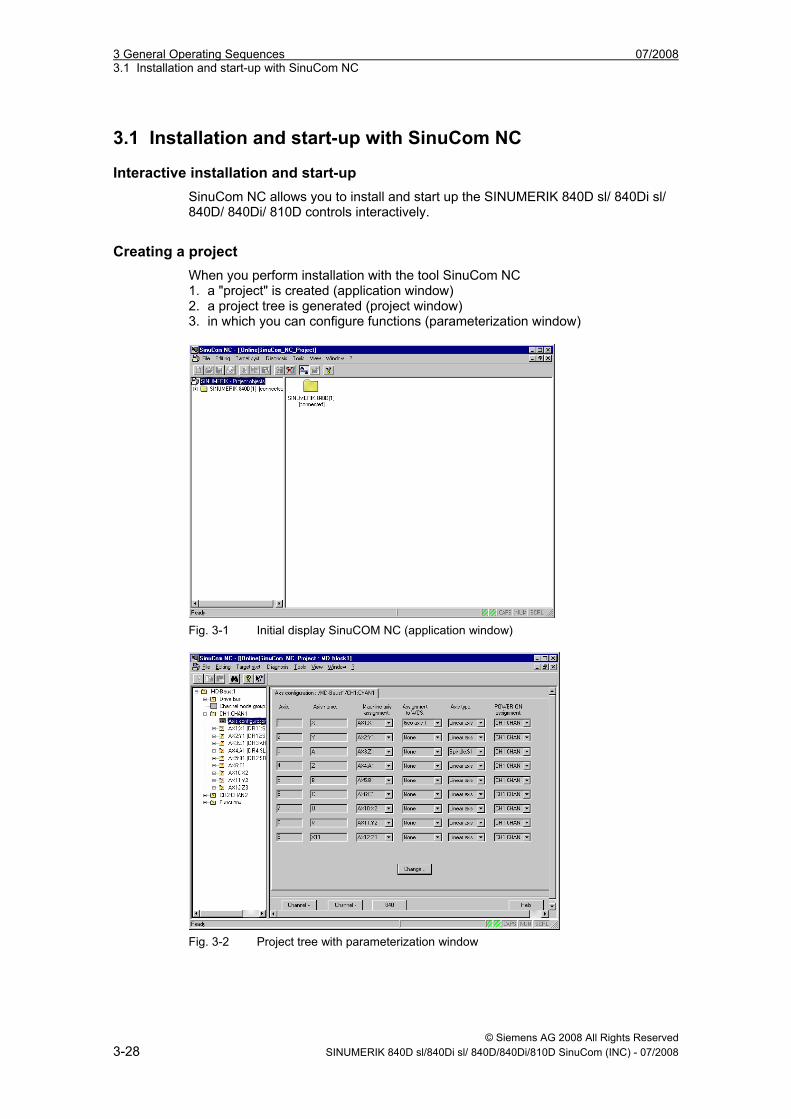
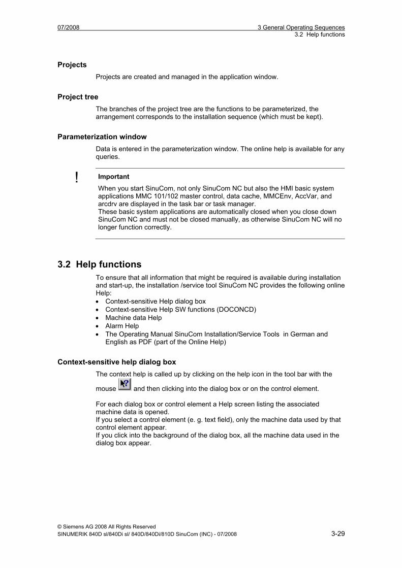
Creating a project When you perform installation with the tool SinuCom NC 1. a "project" is created (application window) 2. a project tree is generated (project window) 3. in which you can configure functions (parameterization window)
Fig. 3-1 Initial display SinuCOM NC (application window)
Fig. 3-2 Project tree with parameterization window
07/2008 3 General Operating Sequences 3.2 Help functions
© Siemens AG 2008 All Rights Reserved SINUMERIK 840D sl/840Di sl/ 840D/840Di/810D SinuCom (INC) - 07/2008 3-29
Projects Projects are created and managed in the application window.
Project tree The branches of the project tree are the functions to be parameterized, the arrangement corresponds to the installation sequence (which must be kept).
Parameterization window Data is entered in the parameterization window. The online help is available for any queries.
! Important
When you start SinuCom, not only SinuCom NC but also the HMI basic system applications MMC 101/102 master control, data cache, MMCEnv, AccVar, and arcdrv are displayed in the task bar or task manager. These basic system applications are automatically closed when you close down SinuCom NC and must not be closed manually, as otherwise SinuCom NC will no longer function correctly.
3.2 Help functions To ensure that all information that might be required is available during installation and start-up, the installation /service tool SinuCom NC provides the following online Help: • Context-sensitive Help dialog box • Context-sensitive Help SW functions (DOCONCD) • Machine data Help • Alarm Help • The Operating Manual SinuCom Installation/Service Tools in German and
English as PDF (part of the Online Help)
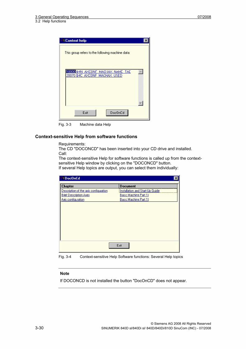
Context-sensitive help dialog box The context help is called up by clicking on the help icon in the tool bar with the
mouse and then clicking into the dialog box or on the control element. For each dialog box or control element a Help screen listing the associated machine data is opened. If you select a control element (e. g. text field), only the machine data used by that control element appear. If you click into the background of the dialog box, all the machine data used in the dialog box appear.
3 General Operating Sequences 07/2008 3.2 Help functions
© Siemens AG 2008 All Rights Reserved 3-30 SINUMERIK 840D sl/840Di sl/ 840D/840Di/810D SinuCom (INC) - 07/2008
Fig. 3-3 Machine data Help
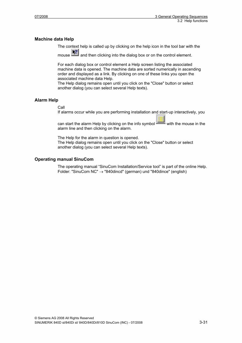
Context-sensitive Help from software functions Requirements: The CD "DOCONCD" has been inserted into your CD drive and installed. Call: The context-sensitive Help for software functions is called up from the context-sensitive Help window by clicking on the "DOCONCD" button. If several Help topics are output, you can select them individually:
Fig. 3-4 Context-sensitive Help Software functions: Several Help topics
Note
If DOCONCD is not installed the button "DocOnCD" does not appear.
07/2008 3 General Operating Sequences 3.2 Help functions
© Siemens AG 2008 All Rights Reserved SINUMERIK 840D sl/840Di sl/ 840D/840Di/810D SinuCom (INC) - 07/2008 3-31
Machine data Help The context help is called up by clicking on the help icon in the tool bar with the
mouse and then clicking into the dialog box or on the control element. For each dialog box or control element a Help screen listing the associated machine data is opened. The machine data are sorted numerically in ascending order and displayed as a link. By clicking on one of these links you open the associated machine data Help. The Help dialog remains open until you click on the "Close" button or select another dialog (you can select several Help texts).
Alarm Help Call If alarms occur while you are performing installation and start-up interactively, you
can start the alarm Help by clicking on the info symbol with the mouse in the alarm line and then clicking on the alarm. The Help for the alarm in question is opened. The Help dialog remains open until you click on the "Close" button or select another dialog (you can select several Help texts).
Operating manual SinuCom The operating manual “SinuCom Installation/Service tool” is part of the online Help. Folder: "SinuCom NC" → "840dincd" (german) und "840dince" (english)
3 General Operating Sequences 07/2008 3.3 Using the keyboard
© Siemens AG 2008 All Rights Reserved 3-32 SINUMERIK 840D sl/840Di sl/ 840D/840Di/810D SinuCom (INC) - 07/2008
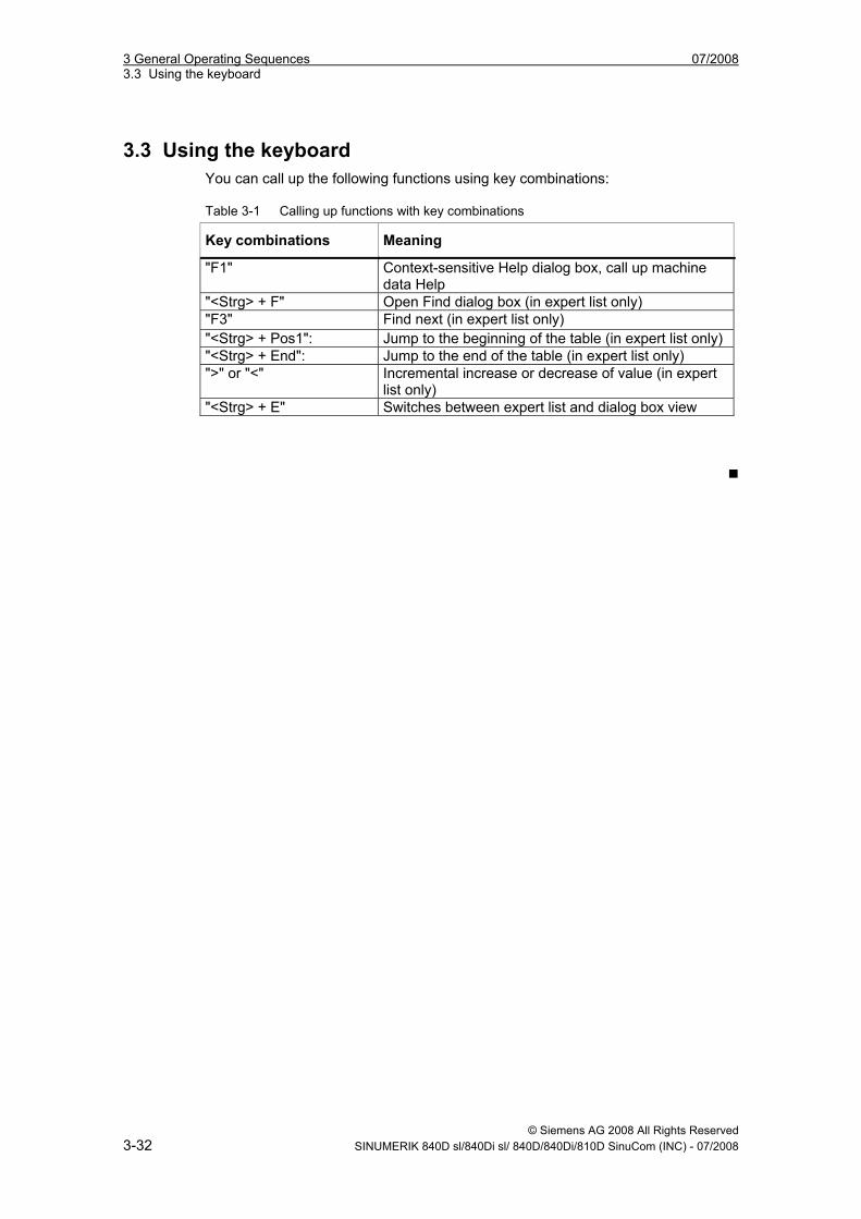
3.3 Using the keyboard You can call up the following functions using key combinations: Table 3-1 Calling up functions with key combinations
Key combinations Meaning
"F1" Context-sensitive Help dialog box, call up machine data Help
"<Strg> + F" Open Find dialog box (in expert list only) "F3" Find next (in expert list only) "<Strg> + Pos1": Jump to the beginning of the table (in expert list only) "<Strg> + End": Jump to the end of the table (in expert list only) ">" or "<" Incremental increase or decrease of value (in expert
list only) "<Strg> + E" Switches between expert list and dialog box view
07/2008 4 SinuCom NC: Functions 4.1 Document Scope and Supported Systems
© Siemens AG 2008 All Rights Reserved SINUMERIK 840D sl/840Di sl/ 840D/840Di/810D SinuCom (INC) - 07/2008 4-33
4 SinuCom NC: Functions
4.1 Document Scope and Supported Systems................................... 4-34 4.1.1 Scope of this Manual ................................................................. 4-34 4.1.2 Supported Systems and NCK Versions .................................... 4-34 4.1.3 Supported Languages ............................................................... 4-34
4.2 What's New in SinuCom NC 7.50................................................. 4-35
4.3 Main Menu .................................................................................... 4-35
4.5 Toolbar Buttons............................................................................. 4-36
4.6 Alarm Messages ........................................................................... 4-36
4.7 Machine Data ("MD") .................................................................... 4-37 4.7.1 Viewing and Configuring MD..................................................... 4-37 4.7.2 Machine Data Project Tree........................................................ 4-39 4.7.3 Service Data .............................................................................. 4-41
4.8 Archiving ....................................................................................... 4-42
4.8 SinuCom NC Trace....................................................................... 4-43 4.9.1 Overview: How Trace is Used ................................................... 4-44 4.9.2 Sessions and Their Content ...................................................... 4-49 4.9.3 Reference Waveforms............................................................... 4-52 4.9.4 Toolbars and Menus.................................................................. 4-54 4.9.5 Context Menus .......................................................................... 4-68 4.8.6 Dialogs....................................................................................... 4-73 4.8.7 Trace Symbol Import Wizard (TSIW) ........................................ 4-88 4.8.8 Trace Setup Wizard (TSW) ....................................................... 4-94
4.9 Safety Integrated Acceptance Test Wizard .................................. 4-99 4.10.1 Example:.................................................................................... 4-99 4.10.2 Common Screen Contents ........................................................ 4-101 4.10.3 Custom Templates .................................................................... 4-104
4
4 SinuCom NC: Functions 07/2008 4.1 Document Scope and Supported Systems
© Siemens AG 2008 All Rights Reserved 4-34 SINUMERIK 840D sl/840Di sl/ 840D/840Di/810D SinuCom (INC) - 07/2008
4.1 Document Scope and Supported Systems
4.1.1 Scope of this Manual This SinuCom NC of the manual supports SinuCom 07.50. For other SinuComs of the software, please consult the corresponding manual.
4.1.2 Supported Systems and NCK Versions SinuCom supports the following SINUMERIK controls: • 840D sl • 840D • 840Di • 810D SinuCom can be combined with NCU 710/ 720/ 730, SW 1.3 (or later) and 810D/ 840D controllere, SW 6.x (or later) An appropriate warning is output if the machine data server from SinuCom is started on older NCK versions. Furthermore, SinuCom outputs various error messages when operated on older NCK versions because these versions are not fully supported. SinuCom NC runs under HMI Advanced resp. HMI Base SW 7.5 (or later). SinuCom NC only runs on Windows XP. SinuCom NC Resource Displays requires NCU SW 6.4 or newer. No alarm will occur on older versions. The feature will simply not be there. SinuCom NC Trace supports full Trace of IPO servo and PLC signals for NCU SW 6.4 (06.04.15.00 or newer versions). SinuCom NC SI Acceptance Test is supported for NCU SW 6.4 (06.04.15.00 or newer versions).
4.1.3 Supported Languages SinuCom supports the same standard languages as Sinumerik.The language setting can be accessed by clicking "Tools" on the main menu. The new language settings is enabled with the next launch of the application.
07/2008 4 SinuCom NC: Functions 4.2 What's New in SinuCom NC 7.50
© Siemens AG 2008 All Rights Reserved SINUMERIK 840D sl/840Di sl/ 840D/840Di/810D SinuCom (INC) - 07/2008 4-35
4.2 What's New in SinuCom NC 7.50 • Not any news
4.3 Main Menu The SinuCom NC main menu is, for the most part, self-explanatory. Rather than listing the functions here that it provides, it is suggested that the user view the selections directly in the product. Non-obvious selections will be addressed in context elsewhere in this manual.
Note
Some menu choices might be permanently grayed out. These menu choices will be used in the future to support features such as Offline SinuCom.
4 SinuCom NC: Functions 07/2008 4.4 Toolbar Buttons
© Siemens AG 2008 All Rights Reserved 4-36 SINUMERIK 840D sl/840Di sl/ 840D/840Di/810D SinuCom (INC) - 07/2008
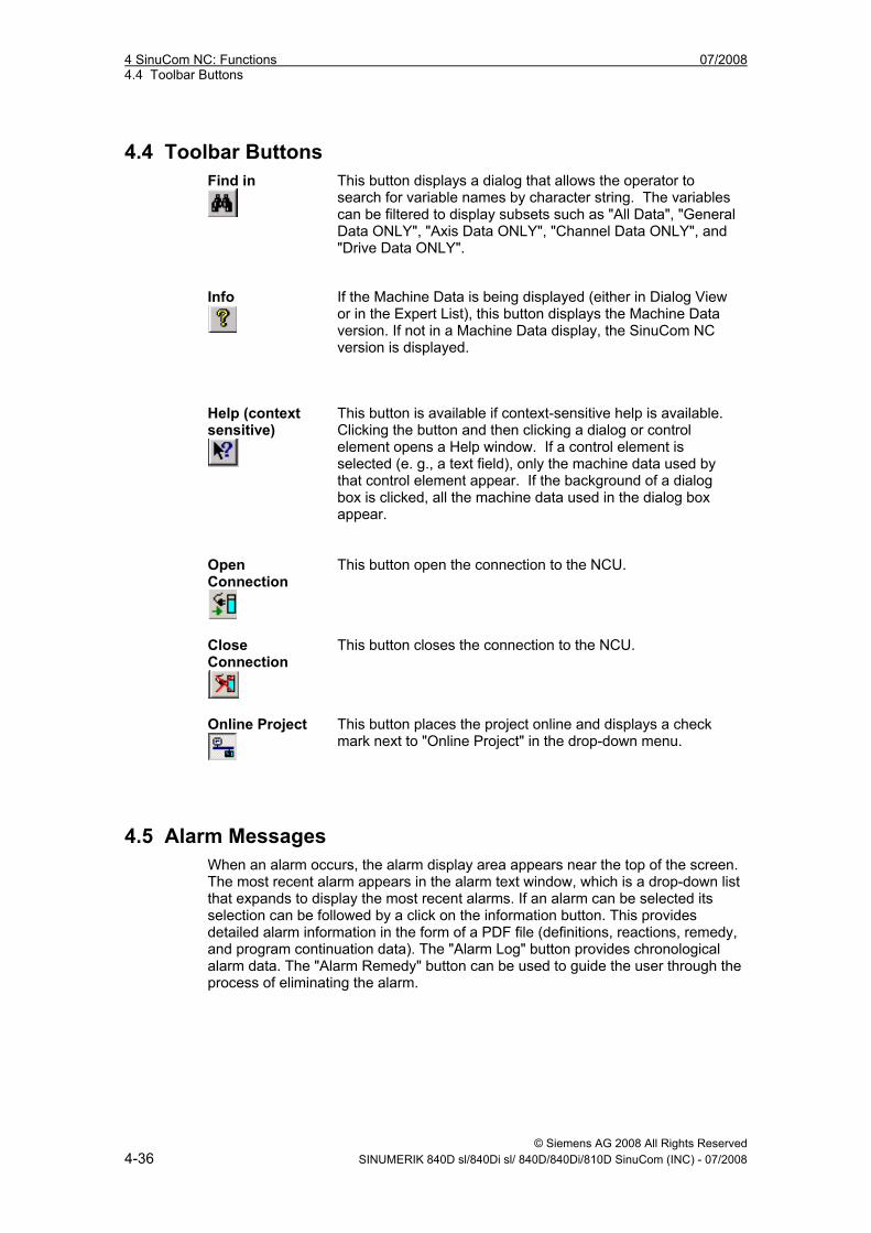
4.4 Toolbar Buttons Find in
This button displays a dialog that allows the operator to search for variable names by character string. The variables can be filtered to display subsets such as "All Data", "General Data ONLY", "Axis Data ONLY", "Channel Data ONLY", and "Drive Data ONLY".
Info
If the Machine Data is being displayed (either in Dialog View or in the Expert List), this button displays the Machine Data version. If not in a Machine Data display, the SinuCom NC version is displayed.
Help (context sensitive)
This button is available if context-sensitive help is available. Clicking the button and then clicking a dialog or control element opens a Help window. If a control element is selected (e. g., a text field), only the machine data used by that control element appear. If the background of a dialog box is clicked, all the machine data used in the dialog box appear.
Open Connection
This button open the connection to the NCU.
Close Connection
This button closes the connection to the NCU.
Online Project
This button places the project online and displays a check mark next to "Online Project" in the drop-down menu.
4.5 Alarm Messages When an alarm occurs, the alarm display area appears near the top of the screen. The most recent alarm appears in the alarm text window, which is a drop-down list that expands to display the most recent alarms. If an alarm can be selected its selection can be followed by a click on the information button. This provides detailed alarm information in the form of a PDF file (definitions, reactions, remedy, and program continuation data). The "Alarm Log" button provides chronological alarm data. The "Alarm Remedy" button can be used to guide the user through the process of eliminating the alarm.
07/2008 4 SinuCom NC: Functions 4.6 Machine Data ("MD")
© Siemens AG 2008 All Rights Reserved SINUMERIK 840D sl/840Di sl/ 840D/840Di/810D SinuCom (INC) - 07/2008 4-37
4.6 Machine Data ("MD")
4.6.1 Viewing and Configuring MD Machine data can be viewed in either the Dialog Display (default) or the Expert List. The Dialog Display provides better navigation and grouping of data points (valuable for the novice) while the Expert List provides more data per screen. The user can toggle between these two display types with "Ctrl - E", or from the "View" menu. The MD Server is started from the project tree (left side of screen) with a machine data block. To do this: • Select "Open Online Project" from either its toolbar button or from "Target Syst."
in the main menu. • Expand the Sinumerik folder, click on "MD Block", then double-click on the "MD-
Block 1" icon. • Click on any element shown under MD-Block 1 in the tree to display or change
that element's configuration.
Note
The units displayed depend on the system of units selected.
Note
Variables that have a white background can be changed. Those that have a gray background are read-only.
The Dialog Display When a folder is selected, the first level dialog is displayed. When a dialog within the folder is selected, the data associated with that dialog is read out of the NC. When the buttons "Channel +" or "Channel -" (or "Axis +", Axis -", etc.) are clicked, the dialog with the data of the next/previous channel is selected. After an NCK reset (warm restart) the project tree and the dialog display are regenerated. When the dialog is exited, the displayed status data is written to the NC.
Note
On single-channel systems the structure view does not contain any channel folders. The axis-specific dialogs are then located directly below the control folder.
4 SinuCom NC: Functions 07/2008 4.6 Machine Data ("MD")
© Siemens AG 2008 All Rights Reserved 4-38 SINUMERIK 840D sl/840Di sl/ 840D/840Di/810D SinuCom (INC) - 07/2008
The Expert List Prior to SinuCom NC 7.3, the Expert List was not configurable. It simply showed all data for the General, Channel, Axis or Drives areas. Starting with SinuCom NC 7.3, all available custom expert lists are offered as well. (A custom expert list is a small subset of data items that are relevant to a particular task, such as Safety Integrated configuration.)
Note
At this time, a custom expert list cannot be edited or created from SinuCom NC. This must be done elsewhere. Reference: Operating Manual, HMI Advanced
All configuration that can be performed with the Dialog Display View can also be performed using the Expert List. The difference is in presentation. The tabular structure of the Expert List offers the experienced user a considerable amount of flexibility without the guiding presence of the Dialog View. Right-clicking anywhere on the grid section of the Expert List brings up a context-sensitive menu of tools for working with the list, as follows: • Find (may not work on custom expert lists) • Find next • Bit Editor * • Display options • Plaintext * The Bit Editor is used to change values that are bit-oriented (i. e., those with the suffix "H", such as "3EABH" or "0H"). The Bit Editor can also be invoked by double-clicking the desired MD item, or just by pressing "5" on the keypad. To assist in searching, four separate Expert List MD ranges can be can be accessed from the project tree: • General MDs • Channel-specific MDs • Axis-specific MDs • Drive MDs. The following key combinations can be used to find and position within the Expert List: Tabelle 4-1 Key combinations ti find and position within The Expert List F1 Opens the Help for the selected machine data Ctrl - F Opens the "Find" dialog box F3 Find next Ctrl - Home Jumps to the beginning of the table Ctrl - End Jumps to the end of the table
07/2008 4 SinuCom NC: Functions 4.6 Machine Data ("MD")
© Siemens AG 2008 All Rights Reserved SINUMERIK 840D sl/840Di sl/ 840D/840Di/810D SinuCom (INC) - 07/2008 4-39
Note
Any Machine Data item can be located in the Expert List via the "Find" dialog using either its MD number or its description. (This "Find" dialog can be invoked by pressing “Ctrl” – “F” from the Expert menu.).
The "<" and ">" keys can be used to make 10% increases and decreases in the values. The color and font of the title, values, table, and status bar can be accessed by selecting "Tools" from the main menu, then "Settings", then "Expert List". The settings take effect immediately and are not lost when the system is restarted.
Changing and Activating MD Effecting a modification in a machine data item is a two-step process: • change the item • activate the item To change a Machine data item: • (Display Dialog View only) If a "Change" button is available, press it to begin the
change. • Place the cursor in the field, or select a drop-down menu. • Key in or select the desired data. • (Expert List only) press "Enter" to complete the change. To activate most changes, the specific action described in the toolbar must be executed (e. g., NCK Reset). Other changes immediately activate.
4.6.2 Machine Data Project Tree
Options Supplementary condition: This option is only valid for 840D sl und 840Di sl. This dialog allows installation of purchased control options, and the associated upgrade of the license key. User guidance for obtaining a license key via the Internet is also available here. A detailed description is included in the following documentation: Literature: SINUMERIK 840Di sl Manual, Chapter: License management
Trace Setup Wizard See the section "Trace Setup Wizard" for more information.
4 SinuCom NC: Functions 07/2008 4.6 Machine Data ("MD")
© Siemens AG 2008 All Rights Reserved 4-40 SINUMERIK 840D sl/840Di sl/ 840D/840Di/810D SinuCom (INC) - 07/2008
Drive Bus Configuration This dialog allows configuration of the drives on the machine.
Channel Mode Group Assignment This dialog allows channels to be assigned to a given mode group, or to no mode group.
Axis Data This extensive dialog allows configuration of the overall complement of machine axes as well as a wide variety of attributes for the individual axes on the machine. It is important to note that the drives for the axes are also setup in this area.
Axis Couplings (Functions) This dialog allows the configuration of coupled axes. It is only visible when one of the following control options is set: • Gantry Axes • Master-Slave Coupling • Synchronous Spindle
Measure (Functions) This dialog is used to set the electrical polarity of each connected sensor (probe).
Protection Zones (Functions) The Protection Zones dialog is used in setting the number of files for machine- and channel-related protection zones.
Resource Displays (Functions) There are four categories of Resource Displays. They can be accessed from the Functions folder in the Machine Data Project Tree: • Clock Rates • Memory • DRAM • SRAM Since these resources are MD variables, they can be viewed and changed as described in the section: "Machine Data". Detailed descriptions and rationale for modification of specific Resource Display parameters is beyond the scope of this manual. For additional information, contact Siemens Support.
07/2008 4 SinuCom NC: Functions 4.6 Machine Data ("MD")
© Siemens AG 2008 All Rights Reserved SINUMERIK 840D sl/840Di sl/ 840D/840Di/810D SinuCom (INC) - 07/2008 4-41
Clock Rates The cycle times and burden on the NCU are displayed so the user can estimate the system basic clock rate and the interpolator clock factor. Data is displayed for Clock Rates of all channels and for individual Channel Clock Rates. If individual Channel Clock Rates are selected, a drop-down list is displayed to select the channel. See the actual display for the specific parameters. Field updates are started and stopped via the "Start" and "Stop" buttons.
Memory This function allows, to allocate the total user memory space for the following two types of RAM: • Static (SRAM) - data needing to be retained (e. g., configuration data). • Dynamic (DRAM) - data not needing to be retained (e. g., current axis position).
DRAM and SRAM These functions allow a piecewise allocation of memory as described by the Resource Display screens provided. (See the specific screen for the actual variables that can be configured.) These memory areas are set to reasonable default subsections during a general NCK reset. To use the user memory optimally, these areas can be adapted by the user by changing the relevant machine data items. This memory configuration comes into effect after an NCK reset.
4.6.3 Service Data The Service Data Display is opened by clicking "Diagnose" in the main menu, then "Service Data". The Service Overview page gives an indication of the overall health of the axes and drives on the machine. The "Axis" display shows the actual and setpoint values for key axis and drive parameters. Beginning with SinuCom NC, a PROFIBUS Diagnostics screen has been added to this area. This screen can show up to three PROFIBUS network types, and can assist in the evaluation of the status of each network
4 SinuCom NC: Functions 07/2008 4.7 Archiving
© Siemens AG 2008 All Rights Reserved 4-42 SINUMERIK 840D sl/840Di sl/ 840D/840Di/810D SinuCom (INC) - 07/2008
4.7 Archiving An archive is a backup of configuration data. The default path for archiving files is the same as that of HMI Advanced. An archive: • can be manually commanded through the SinuCom NC File menu. (This is
recommended prior to making configuration changes to allow recovery from errors.)
• can be required by the system when a change has been made to the NCK that requires memory reorganization. The message "NCK Reset Required" is presented, and an archive is performed during the subsequent reset.
For similar machines, a standard archive can be read in immediately after the installation and first startup of SinuCom NC.
Creating an archive
1. Click "File" → "Archive", then "Create...". The "Create archive" dialog appears. 2. Select one of the following archive choices: − Data management − File system − NC card
3. (840D powerline only) Using the "radio" buttons, select whether the file should
be of type: − "Series Startup" (binary) − "Upgrade" (ASCII)
4. Using the "radio" buttons, select the archive content, which can include any of
the following: • NC (with or without compensation) • PLC • MMC data • Compile cycles • Drive data
5. Click the "Next>" button.
6. At the prompt, enter the desired name and path of the .arc file.
7. Click the "Finish" button to complete the operation.
07/2008 4 SinuCom NC: Functions 4.8 SinuCom NC Trace
© Siemens AG 2008 All Rights Reserved SINUMERIK 840D sl/840Di sl/ 840D/840Di/810D SinuCom (INC) - 07/2008 4-43
Reading In an Archive 1. Click "File" → "Archive", then "Read In...". The "Read in archive" dialog
appears. 2. Select one of the following archive choices:
• Data management • File system • NC card
3. Click the "Next>" button. 4. At the prompt, enter a file name. 5. Click the "Finish" button to complete the operation.
4.8 SinuCom NC Trace
Note
SinuCom NC Trace uses several unique terms. To better understand the descriptions in this section, please review the Appendix entitled "Abbreviations and Definitions - SinuCom NC Trace".
Definition and Use SinuCom NC Trace (also simply called "Trace" in this document) is a SinuCom NC facility that can dynamically record data from the NC, drives, PLC, or HMI. Once recorded, this data can be graphically displayed in a form similar to that of an oscilloscope or logic analyzer, printed, or saved to a file. Saved files can be loaded into Trace for viewing at a later time, even on a different machine. Trace can be used to assist machine manufacturers, end users and Siemens service personnel in activities such as:
• Trouble-shooting and debugging • Machine performance analysis, benchmarking and tuning • Process performance analysis, benchmarking and tuning
Compatibility with Siemens Software NCU 05.03 or NCU 06.03 (basic functionality). NCU 06.04 or later (extended functionality).
Note
The level of available Trace functionality is automatically determined when the NCU SinuCom NC is detected at startup.
4 SinuCom NC: Functions 07/2008 4.8 SinuCom NC Trace
© Siemens AG 2008 All Rights Reserved 4-44 SINUMERIK 840D sl/840Di sl/ 840D/840Di/810D SinuCom (INC) - 07/2008
Compatibility with Microsoft Windows® Trace is a Microsoft Windows® application. It runs on a standard Windows-PC platform under Windows® XP (SP1 or SP2). Common Windows® controls such as scroll bars, toolbars, tabbed dialogs, etc., are used. A mouse or other pointing device is required for selecting, dragging, etc.
Trace’s Relationship to SinuCom NC Trace can be started from SinuCom NC by selecting the Trace menu item from the "Diagnosis" menu. If a Trace session is already active in the NCK when this menu item is selected, SinuCom NC switches to the active Trace session. Trace runs as a separate executable (.exe file) in its own application window. This means that Trace has its own set of menus that do not integrate into the menus of SinuCom NC. These Trace-specific menus are described in the section "Toolbars and Menus".
4.8.1 Overview: How Trace is Used Typically, Trace is used to record data (signals) shortly before or after an event. To do this, the following sequence can be executed: 1. Specify what signals to record.
2. Specify when to start and stop recording (can involve the definition of a trigger
condition).
Note
A mode of operation called “endless collection” can be enabled by simply not specifying a stop condition. (I. e., the recording process continues until it is stopped manually.) This mode operates like a strip chart recorder. Instead of printing on paper, however, when the data storage area becomes full, the oldest data is discarded to make room for the newest. (I. e., the data is stored in a “circular buffer”.)
3. Start the recording process by arming the trigger.
4. The "Awaiting Stop" message is displayed until data collection stops.
Note
If it is desirable to view waveforms as the data as it is collected, the user can set "Keep Data on NCK" off.
07/2008 4 SinuCom NC: Functions 4.8 SinuCom NC Trace
© Siemens AG 2008 All Rights Reserved SINUMERIK 840D sl/840Di sl/ 840D/840Di/810D SinuCom (INC) - 07/2008 4-45
5. View the resulting waveform(s).
6. Manipulate the waveform(s) as desired to examine details (e. g., zoom, scroll, etc.).
7. Optionally, print the waveform(s) or save to a file.
Note
Siemens or the machine builder can supply setup files that are pre-configured for certain tasks such as troubleshooting or performance analysis.
Hands-On Example The easiest way to learn about Trace is to actually use it. This section illustrates the basic use of the tool in step-by-step fashion. 1. Activate SinuCom NC. 2. Click "Diagnosis" in the SinuCom NC main menu. 3. Click "Trace" in the Diagnosis menu. The Trace initial screen will appear.
Note
A yellow (or red) message banner (in this case containing "No Waveforms") is displayed at the top of the graph window. This box can optionally appear whenever a graph window is displayed. It can contain such messages as: • "No Waveforms" – No waveforms have been defined ("added") for display.
• "No Waveforms Shown" – All defined waveforms have had their "Show"
checkbox unchecked, see Figure 4-2. • "Awaiting Stop" – Recording is in process, and the checkbox "Keep data on
NCU until stopped" has been checked (default setting), see Figure 4-5. • "Trace Data has been Lost. Total Segments (x)" – Where "(x)" is the
number of segments lost. (See "Hide Dropouts / Show Dropouts" for additional information on lost data.)
4. Right-click anywhere in the graph window to bring up the "Graph Window
Context Menu". 5. Click the "Add Waveform..." menu item. The "Add Waveform" screen will
appear.
4 SinuCom NC: Functions 07/2008 4.8 SinuCom NC Trace
© Siemens AG 2008 All Rights Reserved 4-46 SINUMERIK 840D sl/840Di sl/ 840D/840Di/810D SinuCom (INC) - 07/2008
6. In the field labeled "Containing:", type "actime". On the right of the screen, three candidates that have this character string in their names are presented.
7. Click the name "acTime" (top selection) to highlight the line it is on. 8. Click the "Add" button. The signal is now ready to be recorded. 9. Click the "Close" button. A graph window will appear without a waveform but
with axis labels and a tab for the new waveform.
10. Click the "Start Trace" icon ( ). The "Trace Status" will change from "Stopped", to "Ready", to "Recording". Data recording is now in process.
11. After a short period of time, click the "Stop Trace" icon ( ). The waveform representing the collected data will be drawn.
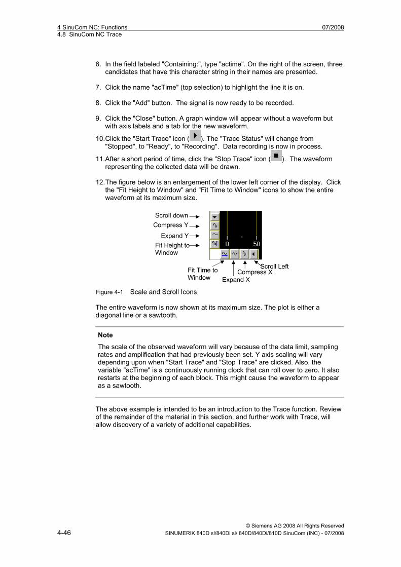
12. The figure below is an enlargement of the lower left corner of the display. Click
the "Fit Height to Window" and "Fit Time to Window" icons to show the entire waveform at its maximum size.
Scroll down
Compress Y
Expand YFit Height toWindow
Fit Time to Window Expand X
Compress XScroll Left
Figure 4-1 Scale and Scroll Icons The entire waveform is now shown at its maximum size. The plot is either a diagonal line or a sawtooth.
Note
The scale of the observed waveform will vary because of the data limit, sampling rates and amplification that had previously been set. Y axis scaling will vary depending upon when "Start Trace" and "Stop Trace" are clicked. Also, the variable "acTime" is a continuously running clock that can roll over to zero. It also restarts at the beginning of each block. This might cause the waveform to appear as a sawtooth.
The above example is intended to be an introduction to the Trace function. Review of the remainder of the material in this section, and further work with Trace, will allow discovery of a variety of additional capabilities.
07/2008 4 SinuCom NC: Functions 4.8 SinuCom NC Trace
© Siemens AG 2008 All Rights Reserved SINUMERIK 840D sl/840Di sl/ 840D/840Di/810D SinuCom (INC) - 07/2008 4-47
Passwords Certain functions of Trace require use of a password: • Variable Selection – Some variables are available for selection only at
approved password levels. If the appropriate password has not been entered, certain variables will not be displayed, and thus cannot be recorded.
• Functions – Some functions are available only at approved password levels. (e. g., selecting signals by address rather than by name).
• Sessions – The creator of a session can make the session read-only or password-accessible. (E. g., a session intended for troubleshooting might be executable by an operator, but its setup can be modified only by a technician.).
Recording Basics: Data and Events There are two main aspects of recording: • The Data aspect (i. e., what to record, sometimes called the “signal”) • The Event aspect (i. e., when to record, on a per-point basis) The Data aspect can be selected as subsets of the following main types of data: • All NC variables (axis data, drive data, channel data, etc.) • Some PLC data The data is usually selected by name, but can also be selected by address. (See the section: "Dialogs", "Dialog: Setup Waveforms"). Note that some types of data require further qualification of the signal. (E. g. "axis data" must also have the specific axis defined.)
Note
“Event-Only” is a special case in which no data is recorded. Only the occurrence of the event is recorded.
4 SinuCom NC: Functions 07/2008 4.8 SinuCom NC Trace
© Siemens AG 2008 All Rights Reserved 4-48 SINUMERIK 840D sl/840Di sl/ 840D/840Di/810D SinuCom (INC) - 07/2008
The Event aspect requires that an "Event" be selected for each waveform.The following list shows three examples of these Events: Events – Partial List Interpolation Cycle (IPO Cycle) IPO interpolation cycle 11 ... ... Prot File Begin start logging ... ... Block Begin S1 block start, w/o intermediate blocks, (all program levels) (preprocessing) ... ... A drop-down menu of all Events is made available when the Event field for the session's first waveform is selected. The selected Event for the first waveform will either be a "preprocessing" or a "non-preprecessing" Event. Within a given session, all Events must be either preprocessing or non-preprocessing. To ensure this continuity, the system will present only the appropriate Events (preprocessing or non-preprocessing) for subsequent waveforms.
1 Events designated as “cyclic” occur repetitively at a constant rate. Waveforms for data re-corded on non-cyclic events have special features and different behaviors as described else-where in this manual.
07/2008 4 SinuCom NC: Functions 4.8 SinuCom NC Trace
© Siemens AG 2008 All Rights Reserved SINUMERIK 840D sl/840Di sl/ 840D/840Di/810D SinuCom (INC) - 07/2008 4-49
4.8.2 Sessions and Their Content
Sessions A Trace Session is an environment constructed for the purpose of collecting data. This data can be used to display one or more waveforms in a configurable manner. The setup (configuration) and the "trace status" (e. g. stopped, recording, no waveform, etc.) are attributes of a session. (I. e., at any given time, a session has a single setup and a single status, independent of other sessions.) More than one session can exist simultaneously. Any or all existing sessions can be operated, and can record independently. A new session can be created at any time (assuming memory, disk space, resources in the NCK, etc., are available). For example, one session can be recording a set of signals while the second session is waiting for a trigger condition. When the recording process is manually started or stopped (i. e., by clicking the
"start trace" button, , or the "stop trace" button, , on the toolbar ), only the active session is affected. (The active session is the session that is currently displayed.) Likewise, when a setup is changed, only the active session is affected. Typically, a session is created by clicking "New Session..." in the file menu. In a future release, a session will also be able to be created by instructions in the NC part program (also called “batch mode”). Session data will be recorded and viewed the same way regardless of which method was used to create it. See also in the section: "Toolbars and Menus", "Open Sessions…" and "Close Sessions…", for file maintenance information, including information on Preserved Sessions.
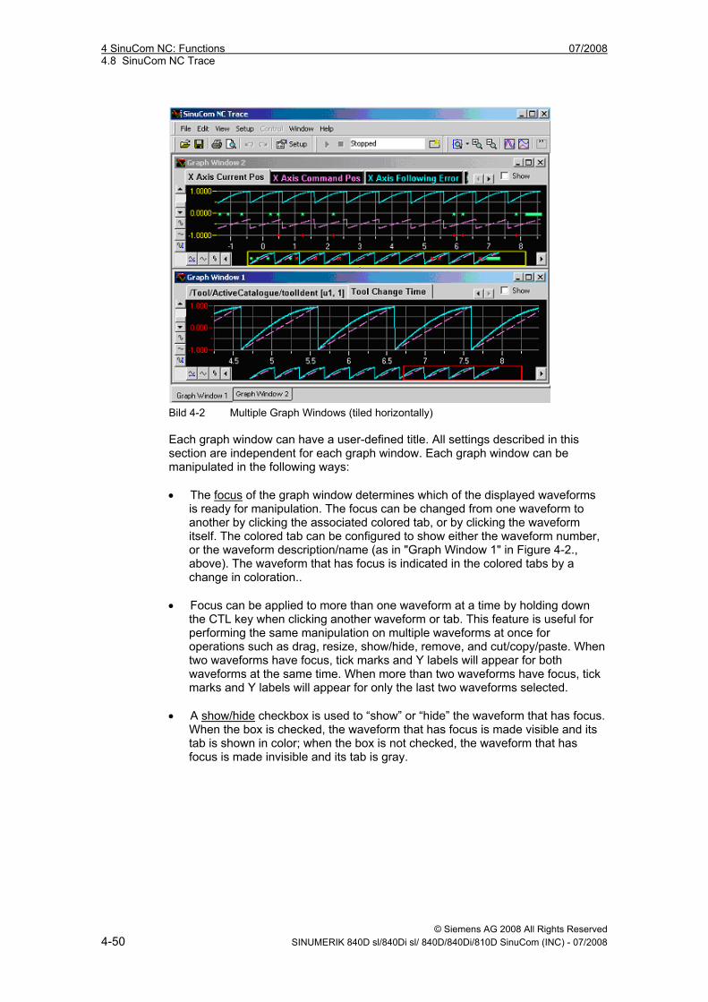
Graph Windows A graph window is the area of the screen where the acquired data is displayed as one or more waveforms. More than one graph window can be displayed, but waveforms in all graph windows must be drawn from the same set of recorded data (within a session). Multiple waveforms can be combined and overlaid in each graph window. Example: Below, shows relationships among four recorded waveforms. Waveforms 1, 2 and 4 are displayed in the upper graph window while waveforms 2 and 3 are displayed in the lower graph window. (Note that a 5th waveform exists but has not been selected for display.) Each graph window can be maximized, minimized, tiled or cascaded according to the normal conventions of Microsoft Windows®.
4 SinuCom NC: Functions 07/2008 4.8 SinuCom NC Trace
© Siemens AG 2008 All Rights Reserved 4-50 SINUMERIK 840D sl/840Di sl/ 840D/840Di/810D SinuCom (INC) - 07/2008
Bild 4-2 Multiple Graph Windows (tiled horizontally) Each graph window can have a user-defined title. All settings described in this section are independent for each graph window. Each graph window can be manipulated in the following ways: • The focus of the graph window determines which of the displayed waveforms
is ready for manipulation. The focus can be changed from one waveform to another by clicking the associated colored tab, or by clicking the waveform itself. The colored tab can be configured to show either the waveform number, or the waveform description/name (as in "Graph Window 1" in Figure 4-2., above). The waveform that has focus is indicated in the colored tabs by a change in coloration..
• Focus can be applied to more than one waveform at a time by holding down the CTL key when clicking another waveform or tab. This feature is useful for performing the same manipulation on multiple waveforms at once for operations such as drag, resize, show/hide, remove, and cut/copy/paste. When two waveforms have focus, tick marks and Y labels will appear for both waveforms at the same time. When more than two waveforms have focus, tick marks and Y labels will appear for only the last two waveforms selected.
• A show/hide checkbox is used to “show” or “hide” the waveform that has focus.
When the box is checked, the waveform that has focus is made visible and its tab is shown in color; when the box is not checked, the waveform that has focus is made invisible and its tab is gray.
07/2008 4 SinuCom NC: Functions 4.8 SinuCom NC Trace
© Siemens AG 2008 All Rights Reserved SINUMERIK 840D sl/840Di sl/ 840D/840Di/810D SinuCom (INC) - 07/2008 4-51
Note
More than one waveform can have focus at the same time. If this is the case, the paragraph above applies to all waveforms that have focus.
• X and Y Axis labels are the numbers displayed next to the ticks marks.They
pertain to the waveform that has focus.These labels change automatically with panning, zooming or change of scale. Numeric resolution (number of decimal places) can also be selected.
• The vertical scroll bars can be clicked or dragged to scroll the off-screen
portions of the graph window into view (i. e., according to the normal conventions of MicroSoft Windows®). The specifics of scrolling and scaling are as follows:
• The horizontal scroll bar is shown as a miniature image of the entire waveform,
(see Figure 4-2) This bar can be moved or dragged just like a standard Windows® scroll bar. Additionally, a rectangle is superimposed onto a portion of the bar which corresponds to the portion of the waveform that is being displayed. This rectangle can be stretched to change the horizontal scaling.
• Along the vertical and horizontal scroll bars, there are buttons to incrementally
stretch or shrink the scaling of the axes. Alternately, the vertical and horizontal axes can be dragged to stretch or shrink the scaling. Also, the "Fit Height to Window" and "Fit Time to Window" buttons can be used to force the entire waveform into view. (See figure "Scale and Scroll Icons").
• After selecting "Zoom X and Y" from the View menu, a portion of the waveform
can be "boxed" (i. e., left mouse button down, then drag, then left mouse button up) in order to zoom to that section (See the section: "Toolbars and Menus", "Menus: View", for details pertaining to the zoom function).
Other aspects of the graph window can be configured, such as graph style, grid lines, scaling style, etc. (See "Dialog: Setup Display“ for details).
4 SinuCom NC: Functions 07/2008 4.8 SinuCom NC Trace
© Siemens AG 2008 All Rights Reserved 4-52 SINUMERIK 840D sl/840Di sl/ 840D/840Di/810D SinuCom (INC) - 07/2008
4.8.3 Reference Waveforms An understanding of the following terms will be beneficial in understanding this section: Waveform - Any single graphical plot of a series of recorded data points. Standard Waveform - A waveform that is updated with new data when the "Record" button is clicked. Reference Waveform - A static waveform that is created from an existing waveform (i. e., from either a standard or reference waveform). This waveform type is NOT updated with new data when the "Record" button is clicked. Copy (a waveform) -The process of selecting a waveform and placing a duplicate on the Windows® clipboard. Such a waveform can subsequently be pasted into a SinuCom NC Trace Session. Insert (a waveform) - The process of placing a duplicate of a waveform from one session into another session. Load (a waveform) - A waveform characterization process that is executed during the opening of a session file. Waveforms can be loaded as either standard waveforms or reference waveforms. A reference waveform can be displayed alongside freshly recorded data, (e. g., to be used as a baseline reference or for comparison to a known data signature). Reference waveforms have many of the characteristics of standard waveforms, and can be manipulated similarly; however, they differ in the following important ways: • They have an "R" prefix before their numeric designation to distinquish them
from standard waveforms. They are also drawn with a dashed line. • Their data and display remains unchanged when a new recording session
begins. (I. e., their data is not updated during a recording session.) • They can be repositioned horizontally (e. g., to synchronize them with
waveforms recorded at a different time.) • They can be created from an existing waveform that has recorded data, either
by "copying" a waveform in the current session or by "inserting" a waveform as reference from another file.
07/2008 4 SinuCom NC: Functions 4.8 SinuCom NC Trace
© Siemens AG 2008 All Rights Reserved SINUMERIK 840D sl/840Di sl/ 840D/840Di/810D SinuCom (INC) - 07/2008 4-53
Creating Reference Waveforms There are three ways to create a reference waveform: 1. By "Copy Waveform / Paste Waveform as Reference". (Note that copy from
session-to-session is supported). 2. When opening a session file, by designating one or more waveforms as
reference (via checkbox). 3. When "Inserting" (i. e., "appending") an existing session file, by designating one
or more waveforms as reference (via checkbox).
Note
Any waveform that had been previously saved without data can only be loaded as a standard waveform.
Note
Edits to waveforms can result in one or more waveforms that consist of individual signals with and without collected data (e. g., non-cyclic signals with the "Same Y" Plot Y option). If an edit creates a waveform with incomplete data, all recorded data for that waveform will be discarded.
Manual Alignment of Reference Waveforms ("Dragging") A reference waveform can be dragged horizontally to visually synchronize it with data captured at a different time. This dragging applies to the display of that waveform in all windows.
Note
When either a reference or standard waveform is hovered over, a directional arrow cursor will be displayed that shows the direction(s) in which dragging is allowed. If no dragging is allowed, a padlock cursor is displayed.
Horizontal dragging is enabled only if none of the following conditions are true: • A zoom tool is selected. (Waveform can be dragged again after the zoom
operation is completed.) • A trace is being recorded. • An annotation is being dragged.
4 SinuCom NC: Functions 07/2008 4.8 SinuCom NC Trace
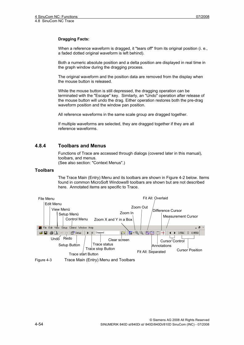
© Siemens AG 2008 All Rights Reserved 4-54 SINUMERIK 840D sl/840Di sl/ 840D/840Di/810D SinuCom (INC) - 07/2008
Dragging Facts: When a reference waveform is dragged, it "tears off" from its original position (i. e., a faded dotted original waveform is left behind). Both a numeric absolute position and a delta position are displayed in real time in the graph window during the dragging process. The original waveform and the position data are removed from the display when the mouse button is released. While the mouse button is still depressed, the dragging operation can be terminated with the "Escape" key. Similarly, an "Undo" operation after release of the mouse button will undo the drag. Either operation restores both the pre-drag waveform position and the window pan position. All reference waveforms in the same scale group are dragged together. If multiple waveforms are selected, they are dragged together if they are all reference waveforms.
4.8.4 Toolbars and Menus Functions of Trace are accessed through dialogs (covered later in this manual), toolbars, and menus. (See also section: "Context Menus".)
Toolbars The Trace Main (Entry) Menu and its toolbars are shown in Figure 4-2 below. Items found in common MicroSoft Windows® toolbars are shown but are not described here. Annotated items are specific to Trace.
File MenuEdit Menu
View MenüSetup Menü
Control Menu Zoom X and Y in a Box
Zoom InZoom Out
Fit All: Overlaid
Difference CursorMeasurement Cursor
Cursor ControlClear screen
Fit All: SeparatedAnnotationsTrace status
Trace stop ButtonTrace start Button
Setup Button
Undo Redo
Cursor Position
Figure 4-3 Trace Main (Entry) Menu and Toolbars
07/2008 4 SinuCom NC: Functions 4.8 SinuCom NC Trace
© Siemens AG 2008 All Rights Reserved SINUMERIK 840D sl/840Di sl/ 840D/840Di/810D SinuCom (INC) - 07/2008 4-55
Menu: File The File “menu” provides access to the following functions: • session management • data export • print management The following selections are available from the menu: New Session… Selection of this item creates a new session. A dialog
containing a suggested session name is presented (e. g., “Session 1”), but any session name can be applied. Selection of this item automatically creates a new graph window for the new session.
Open Session… Selection of this item calls up a sub-menu that allows retreival of a session either "From Preserved Sessions List" or "From Session File". (See the two descriptions with these titles directly below.) Note When a session is retreived, it becomes the active session. (I. e., it replaces any currently-displayed session.) From Preserved Session List… Selection of this item opens the Preserved Sessions dialog. This dialog presents a list of sessions that are currently preserved in the NCU. Any entry in the list can be selected, making it the active session. From Session File… Selection of this item allows a saved session file to be opened using the standard MicroSoft Windows® "Open" dialog. Selection of a specific file calls up the "Select Session Contents to Load" dialog. Via checkbox, this dialog allows the loading of the following: • Setup Waveforms, Collection and Triggers • Setup Display • All Waveform Data
If signal data is loaded, it is immediately displayed just as if it had been freshly recorded.
4 SinuCom NC: Functions 07/2008 4.8 SinuCom NC Trace
© Siemens AG 2008 All Rights Reserved 4-56 SINUMERIK 840D sl/840Di sl/ 840D/840Di/810D SinuCom (INC) - 07/2008
Note
Siemens or the OEM can provide pre-configured session files for common tasks. If this is the case, only the session file needs to be loaded to obtain the desired setup. A new session can also be created with this information. This would allow the previously active session to reside in its window rather than over-writing it. After this waveform data is loaded, it is presented in the graph window(s) as the active session, just as if the session had not been interrupted; however, its data will be lost the next time recording is started.
Open Session... (continued)
When opening from a Session File, only the data associated with a waveform could be suppressed. Decide via checkbox:
1. whether or not to load each waveform. 2. whether to load each waveform as reference or
standard.
Close Session… Selection of this item closes the active (current) session and calls up a dialog that provides the option of either discarding or preserving the session and its recorded data. If "Preserve Session" is selected, the session will be maintained in the NCU even if the Trace application is exited and even if the NCU is shut down. The preserved session maintains: • the NCU resources • the entire setup • the recorded signal data (if any).
At some later time, Trace can be reconnected to a preserved session. (See "Open Session.." for information about reconnecting to a preserved session.) This reconnection allows work with the session to resume. If any signal data was recorded by the NCU while the Trace was disconnected, the HMI will retrieve that recorded data immediately upon reconnection to the session.
Save Session… Selection of this item opens the "Save Session" dialog.
Either "Save Session to File" or "Preserve Session on NCU" (or both) must be checked in order to perform a save. The "Advanced >>" button can be pressed to allow checkbox selection of a only a subset of the waveforms and parameters to be saved. If the Advanced window is not used, all setup parameters and the waveforms will be saved to the file.
07/2008 4 SinuCom NC: Functions 4.8 SinuCom NC Trace
© Siemens AG 2008 All Rights Reserved SINUMERIK 840D sl/840Di sl/ 840D/840Di/810D SinuCom (INC) - 07/2008 4-57
A path is initially suggested (e. g., "f:\user\"). A filename
must be specified. Optionally, a new path can precede the filename. If this is done, the suggested path disappears. In subsequent saves, the new path becomes the suggested path. At some later time, the sequence "File...Open Session...From Session File" can be used to reload the file. Note A saved session file that includes waveform data can be used later to load reference waveforms, See the section: "Sessions and Their Content", "Reference Waveform", for information on the use of Reference Waveforms.)
Save Image… Selection of this item calls up a standard MicroSoft Windows® “Save As” dialog that allows the image of the active graph window to be saved to a Windows graphic metafile or bmp. This graphic metafile contains the graphical content of the graph window including waveforms, axis scales, and annotations, but excludes borders, scrollbars, tabs, etc. Note A Windows® metafile is a format that can be resized without losing detail.
Import Symbols Selection of this item opens the Trace Symbol Import Wizard. The function of this tool is self-explanatory. This wizard allows manually update GUDs and PLC Variables at any time.
Export Waveforms…
Selection of this item opens the "Export Waveforms" dialog, The "Advanced >>" button can be pressed to allow checkbox selection of a only a subset of the waveforms to be exported. If the Advanced window is not used, all waveforms will be saved to the file. A path is initially suggested (e. g., "f:\user\"). A filename must be specified. Optionally, a new path can precede the filename. If this is done, the suggested path disappears. In subsequent saves, the new path becomes the suggested path. Unlike a saved Session, an exported waveform file cannot be reloaded and re-displayed.
Note Unlike the XML format of a saved session, an exported waveform is a numerical representation of the waveforms to be saved in a comma-delimited (.csv) format. This format can be easily imported into other applications such as Microsoft Excel.
4 SinuCom NC: Functions 07/2008 4.8 SinuCom NC Trace
© Siemens AG 2008 All Rights Reserved 4-58 SINUMERIK 840D sl/840Di sl/ 840D/840Di/810D SinuCom (INC) - 07/2008
Print Preview Selection of this item displays a preview of the impending printout in standard MicroSoft Windows® Print Preview format.
Print… Selection of this item opens the Print dialog.
(Note that toggling "Page Setup >>" alternately compresses, then expands the lower portion of the screen.). This print dialog has functionality similar to that of many MicroSoft® products, but also has the following two capabilities: • Print Range - The following two choices are provided:
- Full Range Prints the full recording, on multiple pages if required.
- Current view only Prints only the content currently in view.
• Image Size - The following three choices are provided: - Actual Size
The size of the display will be reproduced in print, pixel-for-pixel at 100% of its size. One screen of data will be produced per page. If the screen is larger than the page (X and/or Y), a portion of the printout will be cut off.
- Full Page ("preserve aspect ratio" checked) The displayed size ratio of X to Y is preserved. The on-screen waveform will be enlarged to either the full horizontal or full vertical dimension of the page (whichever is reached first).
- Full Page ("preserve aspect ratio" not checked) Both the X and Y dimension of the on-screen waveform will be enlarged to the size of the page without regard to the displayed size ratio of X to Y. Significant distortion is expected unless the aspect ratio of the display is close to the aspect ratio of the page.
• Print Color Scheme - The following three choices are
provided: - Black and white printer scheme - Color printer schemeo - Same as display
07/2008 4 SinuCom NC: Functions 4.8 SinuCom NC Trace
© Siemens AG 2008 All Rights Reserved SINUMERIK 840D sl/840Di sl/ 840D/840Di/810D SinuCom (INC) - 07/2008 4-59
Note
Any printout will contain the graphical content of the graph window (waveforms, axis scales, and annotations), but borders, scrollbars, tabs, etc. will be excluded. The displayed scaling of the graphs will be reflected in the printout.
Exit Trace Selection of this item exits the Trace facility.
Menu: Edit The following “Edit” Menu functions are available for text editing: Undo Selection of this item will perform an Undo (revert) on the last
action (if possible). Possible actions for undo include scaling and zooming of graph windows, and various changes to setup parameters. Undo will not be available for actions that involve the actual recording of data or clearing of recorded data.
Redo Each redo restores an undo operation until the state prior to first undo operation is achieved. Note If an undo-redo operation is performed on a setup parameter while the Setup dialog is visible, the dialog is automatically switched to the page that contains the changed parameter.
4 SinuCom NC: Functions 07/2008 4.8 SinuCom NC Trace
© Siemens AG 2008 All Rights Reserved 4-60 SINUMERIK 840D sl/840Di sl/ 840D/840Di/810D SinuCom (INC) - 07/2008
The following Edit Menu functions are available for waveform editing: Cut Waveform Removes the waveform from the session and moves it -- and
its data -- onto the Windows® clipboard.
Copy Waveform Leaves the waveform in the session and moves a copy of it -- and its data -- onto the Windows® clipboard.
Paste Waveform as Standard
Pastes the waveform on the Windows® clipboard into the session as a Standard Waveform at the end of the waveform order. It can subsequently be dragged to another position in the order. Note Standard waveforms, if pasted in the same session, are always pasted with data. To prevent invalid mixes of data, a waveform pasted into a different session will be pasted without data. Application Hint: Multiple copies of a Standard Waveform can be pasted into the same session, and can subsequently be given a different bit field specification. Each will be redrawn according to its specific bit field.
Paste Waveform as Reference
Pastes the waveform on the Windows® clipboard into the session as a Reference Waveform at the end of the waveform order. It can subsequently be dragged to another position in the order. Standard waveforms are pasted with data. Note Reference Waveforms are always pasted with data. If a waveform has no data it must be pasted as a Standard Waveform.
07/2008 4 SinuCom NC: Functions 4.8 SinuCom NC Trace
© Siemens AG 2008 All Rights Reserved SINUMERIK 840D sl/840Di sl/ 840D/840Di/810D SinuCom (INC) - 07/2008 4-61
Scale Grouping Note
Scale Grouping and Multiple Selection are similar (e. g., whenever any one waveform is compressed or expanded, all associated waveforms are compressed or expanded), but they have two major differences:
1. Scale Grouping is more permanent. (I. e., waveforms in a Scale Group stay together until explicitly split apart; waveforms under Multiple Selection stay together only until another selection is made.) 2. All waveforms in a Scale Group have the same Y axis scaling.
To perform a multiple selection:
1. Click on any waveform (or its tab) to select it. 2. Ctrl-click any other waveform (or its tab) to add it to
the selection. 3. Repeat step 2 to add additional waveforms.
To perform a scale grouping:
1. Perform a multiple selection, as described directly above.
2. Select "Scale Grouping" from the Edit drop-down menu.
Scale Grouping (cont.)
Selection of Scale Grouping opens a submenu with three choices, as described below. A table of scenarios is shown for each. For these tables, the following rules apply: • Group names "A" and "B" designate existing groups. • Group name "C" designates a resulting group. • "0" indicates an independent (ungrouped) waveform. • A BOLD "A", "B" or "C" is a selected waveform.
Note If possible, existing group names are preserved. • Group
This choice is available if two or more waveforms are selected. Selection brings up the "Scale Group Properties" dialog, in which the group (i. e., all selected waveforms) can be given a unique name. Radio buttons allow the waveforms to share the "same Y scale" and optionally the "same Y position".
4 SinuCom NC: Functions 07/2008 4.8 SinuCom NC Trace
© Siemens AG 2008 All Rights Reserved 4-62 SINUMERIK 840D sl/840Di sl/ 840D/840Di/810D SinuCom (INC) - 07/2008
The following table describes grouping behavior:
"Group" Scenarios
Menu State
Initial Condition
Resulting Effect
One waveform selected grayed AAABB no effect Selection spans groups normal AAABB AACC0 Subset of group selected normal AAA AA0 Subset of large group selected normal AAAA AACC Selection contains ungrouped waveforms normal AA0000 AAAA00 Entire group selected normal AAAA no effect
Scale Grouping (cont.)
• Ungroup This choice is available if the selection contains at least one waveform that belongs to a group. Selection will either cause a simple group to "ungroup", or will cause one of the other resulting effects as described in the following table:
"Ungroup" Scenarios Menu
State Initial Condition
Resulting Effect
Subset Selected normal AAAABB 00AABB Selection spans groups grayed AAABB no effect Set minus one element normal AAA 000 Entire set selected normal AAA 000 Selection includes unselected normal AAA0 AA00
Scale Grouping (cont.)
• Select Entire Group This choice is available when a selection contains one or more waveforms from a single group, and no others. It is useful for: - seeing the full complement of signals for a given
group. - adding a waveform to a group. To do so:
Right-click on a waveform in the target group Click on "Scale Grouping". Click on "Select Entire Group". <ctrl> click the waveform to be added. Click on "Scale Grouping". Click on "Group" to add the waveform to the group.
- performing an operation on an entire group (i. e., making sure a group is completely disbanded.)
07/2008 4 SinuCom NC: Functions 4.8 SinuCom NC Trace
© Siemens AG 2008 All Rights Reserved SINUMERIK 840D sl/840Di sl/ 840D/840Di/810D SinuCom (INC) - 07/2008 4-63
The following scenarios apply:
"Select Entire Group" Scenarios Menu
State Initial Condition
Resulting Effect
One item selected normal AAABB AAABB Selection spans groups grayed AAABB no effect Subset of group selected normal AAA AAA Subset of large group selected normal AAAA AAAA Selection spans unselected items grayed AA00 no effect
Menu "View" The View menu allows waveforms to be enlarged, reduced, repositioned, and labeled. The following selections are available from the menu: Show Custom View
Selection of this item returns the scaling and position of all waveforms to a previously-established state called the "Custom View". If no Custom View has been set, the initial view is used. Note Establishing a Scale Grouping overrides a Custom View.
Set Custom View Selection of this item establishes the current view as the Custom View.
Control Scale > Selection of this item allows manipulation of vertical and time scaling through a submenu consisting of the following choices:
Set Vertical Scale Selection of this item invokes a dialog that allows
numeric min and max vertical scale values to be set for the active waveform(s). (This is especially useful if the Y values of two or more waveforms are to be visually compared.)
Lock Vertical Drag
Prohibits the vertical dragging of the selscted waveform(s).
Unlock Vertical Drag
Enables the vertical dragging of the selected waveform(s).
Set Time Scale Selection of this item invokes a dialog which allows numeric min and max horizontal scale values to be set (all waveforms).
Lock All Vertical Drag
Prohibits the vertical dragging of all waveforms.
Unlock All Vertical Drag
Enables the vertical dragging of all waveforms.
4 SinuCom NC: Functions 07/2008 4.8 SinuCom NC Trace
© Siemens AG 2008 All Rights Reserved 4-64 SINUMERIK 840D sl/840Di sl/ 840D/840Di/810D SinuCom (INC) - 07/2008
Zoom > Selection of this item allows zooming through a submenu
consisting of the following choices: Zoom X and Y Selection of this item allows an area of the display
to be magnified in both the X and Y direction. A portion of the waveform can be dragged over (i. e., left mouse button down, then drag, then left mouse button up) in order to zoom to that section. The proportion of X-to-Y is dictated by the proportion of the zoom box.
Zoom X only Selection of this item is the same as Zoom X and Y, but only the X dimension is zoomed.
Zoom Y only Selection of this item is the same as Zoom X and Y, but only the Y dimension is zoomed.
MODAL ZOOM: The three zoom capabilities directly above involve dragging the mouse. Their capability can be enhanced by MODAL ZOOM. This mode can be locked on by double-clicking the zoom button on the toolbar. While in modal zoom, the selected area can be zoomed repeatedly by dragging, without having to click the zoom button again. Modal zoom is unlocked by clicking the zoom button again, or by clicking anywhere in the graph window without dragging.
Zoom In Selection of this item causes the display to be
enlarged by a preset amount. The center of the display is maintained.
Zoom Out Selection of this item causes the display to be reduced in size by a preset amount. The center of the display is maintained.
Fit All: Overlaid Selection of this item fits all waveforms to maximum size. Since all waveforms occupy the full extent of the vertical screen, they are "overlaid" with each other.
Fit All: Separated Selection of this item divides the screen into partitions, one partition for each visible waveform (or scale group if any waveforms are grouped). Each waveform is displayed to its maximum vertical size within its partition.
07/2008 4 SinuCom NC: Functions 4.8 SinuCom NC Trace
© Siemens AG 2008 All Rights Reserved SINUMERIK 840D sl/840Di sl/ 840D/840Di/810D SinuCom (INC) - 07/2008 4-65
Annotations Repetitive selection of this item toggles the
annotations on and off for all displayed waveforms. Note Annotations are color-coded waveform names. The names are derived from the Waveforms Setup. If a Description has been supplied in the Waveforms Setup, it is the annotation. Otherwise, the Waveform Name is the annotation. Note Both the annotation and its arrow can be dragged to a new position on the screen. The arrowhead remains stationary when the annotation is dragged; the arrow remains parallel to its original orientation when the arrow is dragged.
Difference Repetitive selection of this item turns the difference cursors, and their associated dialog display, on and off. (see a description of "Difference Cursors".)
Measurement Repetitive selection of this item toggles the display of the measurement cursors as well as their control/display features on the measurement toolbar, see the section: "Dialogs", "Measurement Cursor", for information on the use of the Measurement Cursor.)
Show All Waveforms
Selection of this item causes all waveforms to be visible.
Hide All Waveforms
Selection of this item causes all waveforms to be hidden.
Hide Dropouts / Show Droputs
Selection of this items turns the visible state of all dropout indicators on and off. (A dropout indicator is a pair of vertical lines that shows when a dropout begins and ends.
Note A dropout indicator is a pair of vertical lines that shows where a dropout begins and ends. (A dropout is a portion of a waveform for which the signal data is not available.) Note Dropouts can occur for a number of reasons, but the most common reason is that Trace could not process the signal data as fast as it was being accumulated at the signal source.
4 SinuCom NC: Functions 07/2008 4.8 SinuCom NC Trace
© Siemens AG 2008 All Rights Reserved 4-66 SINUMERIK 840D sl/840Di sl/ 840D/840Di/810D SinuCom (INC) - 07/2008
Toolbars This menu item allows the display of individual
toolbars to be turned on and off (e. g. the Control toolbar).
Menu "Insert" The following selections are available from the menu: Add Waveform... Directs focus to the "Add Waveform" dialog.
Waveforms Allows the introduction of an additional waveform
into the correct session either from a file or from another session.
Menu "Setup" The Setup menu provides access to the Setup dialog. Each menu item allows quick access to a particular page of the Setup dialog. Alternately, the Setup toolbar button calls up the Setup dialog to the page last used. The following selections are available from the menu: Waveforms… This menu item opens the Setup dialog with the Waveforms
page selected. (See the section: "Dialogs", "Dialog: Setup Waveforms").
Collection… This menu item opens the Setup dialog with the Collections page selected (See the section: "Dialogs", "Dialog: Setup Collection").
Trigger… This menu item opens the Setup dialog with the Trigger page
selected. (See the section: "Dialogs", "Dialog: Setup Trigger").
Sample Rates This menu item opens the Setup dialog with the Sample Rates page selected, (See the section: "Dialogs", "Dialog: Setup Trigger").
Display… This menu item opens the Setup dialog with the Display page selected, (See the section: "Dialogs", "Dialog: Setup Display").
07/2008 4 SinuCom NC: Functions 4.8 SinuCom NC Trace
© Siemens AG 2008 All Rights Reserved SINUMERIK 840D sl/840Di sl/ 840D/840Di/810D SinuCom (INC) - 07/2008 4-67
Menu "Control" The Control menu allows the recording process to be started and stopped, and the screen to be cleared. The trace status window indicates one of the following states • Stopped • Waiting for trigger • Recording The following selections are available from the menu: Start
Selection of this item makes Trace ‘active’, and initiates monitoring for the trigger condition. If no trigger condition has been defined, recording begins immediately upon Start. If the setup parameter Auto-start at power-on is set True, monitoring for the trigger condition starts automatically at power-on.
Stop
Selection of this item makes Trace ‘inactive’, and stops recording or stops waiting for the trigger condition. This action is not needed if recording stops automatically because the recording duration is satisfied.
Clear
Selection of this item clears the current graph window of any waveforms.
Menu "Window" The Window menu provides features comparable to its MicroSoft Windows® counterpart. In addition to windows arrangement and control, it allows multiple graph windows to be created and manipulated. All graph windows draw from the same acquired data, but each window can be manipulated independently. The following selections are available from the menu: New Window Selection of this item creates a new graph window. The new
window becomes the new active session. Waveforms in the new window are a copy of the old window. This allows manipulation in the new active window without change in the old. When more than one window is present, tabs appear below the windows to allow for quick selection with the mouse. Note Multiple windows allow convenient waveform comparison. They also can relieve clutter by grouping sets of relevant waveforms and eliminating irrelevant ones.
4 SinuCom NC: Functions 07/2008 4.8 SinuCom NC Trace
© Siemens AG 2008 All Rights Reserved 4-68 SINUMERIK 840D sl/840Di sl/ 840D/840Di/810D SinuCom (INC) - 07/2008
Cascade Selection of this item arranges all windows in an overlapped
fashion.
Tile Horizontally Selection of this item arranges all windows in non-overlapped horizontal tiles.
Tile Vertically Selection of this item arranges all windows in non-overlapped vertical tiles.
Graph Window n This menu item selects a particular graph window for viewing. This menu item is repeated for each available graph window.
4.8.5 Context Menus A context menu is a pop-up menu that appears when the right mouse button is clicked over a specific area or type of item. It appears at the click point and is context-specific (i. e., the items in the menu will vary depending on the area clicked.) Context menu items are often the same items found on normal menus, but they provide an alternate way to quickly access functions that apply to the area that was clicked.
Context Menu: Graph Window This context menu appears when any empty space in the graph window is right-clicked (i. e., where there is no waveform). Add Waveform This menu item opens the Add Waveform dialog (identical to
the "Dialog: Setup Display")
Setup This menu item cascades to a sub-menu that is identical to that found under "Menu: Setup".
New Session This menu item is identical to the one of the same name found under "Menu: File".
Cut Waveform This menu item is identical to the one of the same name found under "Menu: Edit".
Copy Waveform This menu item is identical to the one of the same name found under "Menu: Edit".
07/2008 4 SinuCom NC: Functions 4.8 SinuCom NC Trace
© Siemens AG 2008 All Rights Reserved SINUMERIK 840D sl/840Di sl/ 840D/840Di/810D SinuCom (INC) - 07/2008 4-69
Paste Waveform as Standard
This menu item is identical to the one of the same name found under "Menu: Edit".
Paste Waveform as Reference
This menu item is identical to the one of the same name found under "Menu: Edit".
Edit Graph Window Colors
This menu item opens the Graph Window Colors dialog (identical to the dialog accessed by the "Colors" button in the Setup Display Dialog.
Show All Waveforms
This menu item is identical to the one of the same name found under "Menu: View".
Hide All Waveforms
This menu item is identical to the one of the same name found under "Menu: View".
Hide Dropouts This menu item is identical to the one of the same name found under "Menu: View".
Show Custom View
This menu item is identical to the one of the same name found under "Menu: View".
Set Custom View This menu item is identical to the one of the same name found under "Menu: View".
Control All Scales
This menu item cascades to a sub-menu with the following selections: Set Time Scale Lock All Vertical Drag Unlock All Vertical Drag Fit Time to Window Descriptions for these choices can be found under "Menu: View".
Zoom This menu item cascades to a sub-menu with the items under "Menu: View" used for zooming and scaling.
Annotations This menu item is identical to the one of the same name found on the "Menu: View".
4 SinuCom NC: Functions 07/2008 4.8 SinuCom NC Trace
© Siemens AG 2008 All Rights Reserved 4-70 SINUMERIK 840D sl/840Di sl/ 840D/840Di/810D SinuCom (INC) - 07/2008
Context Menu: Waveform This context menu appears when a waveform or waveform tab is right-clicked. Add Waveform This menu item opens the Add Waveform dialog (identical to
the "Dialog: Setup Waveforms").
Edit Waveform This menu item opens the Edit Waveform dialog (identical to the dialog accessed by the "Edit" button in the "Dialog: Setup Waveforms").
Remove Waveform
This menu removes the selected waveform(s) (identical to the dialog accessed by the "Remove" button in the "Dialog: Setup Waveforms").
Cut Waveform This menu item is identical to the one of the same name found under "Menu: Edit".
Copy Waveform This menu item is identical to the one of the same name found under "Menu: Edit".
Paste Waveform as Standard
This menu item is identical to the one of the same name found under "Menu: Edit".
Paste Waveform as Reference
This menu item is identical to the one of the same name found under "Menu: Edit".
Edit Style This menu item opens the Waveform Style dialog (identical to the dialog accessed by the "Edit" button in the "Dialog: Setup Waveforms").
Edit Description This menu item moves the cursor to the waveform's tab, allowing immediate editing of the waveform description.
Show Waveform This menu item causes the waveform to be visible (identical to checking the "Show" checkbox shown in Figure 4-2).
Hide Waveform This menu item causes the waveform to be hidden (identical to unchecking the "Show" checkbox shown in Figure 4-2 (tiled horizontally)).
Control Vertical Scale > (formerly "Resize Waveform)
Selection of this item allows manipulation of vertical scaling through a submenu consisting of the following choices:
07/2008 4 SinuCom NC: Functions 4.8 SinuCom NC Trace
© Siemens AG 2008 All Rights Reserved SINUMERIK 840D sl/840Di sl/ 840D/840Di/810D SinuCom (INC) - 07/2008 4-71
Set Vertical Scale
This menu item is identical to the one of the same name found under "Menu: Edit".
Lock Vertical Drag
This menu item is identical to the one of the same name found under "Menu: Edit".
Unlock Vertical Drag
This menu item is identical to the one of the same name found under "Menu: Edit".
Fit Height to Window
This menu item performs a function identical to the "Fit Height to Window" icon found in Figure 4-1.
Scale Grouping This menu item is identical to the one of the same name
found under "Menu: Edit".
Waveform Tabs This menu item cascades to a sub-menu with the following selections: Show Text Show Numbers Show Both These choices are duplicates of the ones found in the "Dialog: Setup Display".
Annotations This menu item is identical to the one of the same name found under "Menu: View".
4 SinuCom NC: Functions 07/2008 4.8 SinuCom NC Trace
© Siemens AG 2008 All Rights Reserved 4-72 SINUMERIK 840D sl/840Di sl/ 840D/840Di/810D SinuCom (INC) - 07/2008
Context Menu: Setup Waveform Dialog This context menu appears when the Setup Waveform Dialog is right-clicked. Add Waveform This menu item opens the Add Waveform dialog (identical to
the "Dialog: Setup Waveforms").
Edit Waveform This menu item cascades to a sub-menu with the following selections: Edit Style (identical to "Edit Style") Edit Description (identical to "Edit Description"). Edit Signal Specification (identical to "Edit Wave form"). Edit Bitmask (opens the Bit Editor Dialog [identical to the dialog accessed by the "Bit" button in the Edit Waveform Dialog. See also "Bit Mask").
Remove Waveform
This menu removes the selected waveform (identical to the dialog accessed by the "Remove" button in the "Dialog: Setup Display").
Cut Waveform This menu item is identical to the one of the same name found under "Menu: Edit".
Copy Waveform This menu item is identical to the one of the same name found under "Menu: Edit".
Paste Waveform as Standard
This menu item is identical to the one of the same name found under "Menu: Edit".
Paste Waveform as Reference
This menu item is identical to the one of the same name found under "Menu: Edit".
Event Data Display More than one data item can be recorded on the same event. If this occurs, a single marker (point) will be visible, but others may be hidden directly below it. To see all of the data represented by the single marker, the mouse pointer can be moved (hovered) over the plot marker. After a brief delay, a window will temporarily appear near the marker (until the mouse is moved again). This window displays the name of the event, followed by the name or description and value of each data item recorded on that event. If the mouse is clicked on the event marker, this window remains displayed on the screen if the mouse is moved or clicked elsewhere. The Close button dismisses this window.
07/2008 4 SinuCom NC: Functions 4.8 SinuCom NC Trace
© Siemens AG 2008 All Rights Reserved SINUMERIK 840D sl/840Di sl/ 840D/840Di/810D SinuCom (INC) - 07/2008 4-73
4.8.6 Dialogs Most Trace dialogs pertain to the presentation of waveforms. They are called Setup Dialogs (described below). Dialogs are interactive displays. They are called dialogs because have three major functions. Each one: 1. displays a category of information. 2. allows the modification of this information. 3. feeds back the effects of the updated information.
Setup Dialogs As stated above, Setup Dialogs control the presentation of the waveforms. They are used to identify what data to record and when to record it. When either the Setup Menu or Setup Button is clicked (as shown in Figure 4-3), the Setup Dialogs are presented as the following group of tabbed pages: • Waveforms • Collection • Trigger • Sample Rates • Display
Dialog: Setup Waveforms This dialog facilitates the preparation for waveform recording, including the selection of signals to be recorded. It presents a table of all signals that are currently selected. As much as possible, only choices that result in a valid configuration are presented. The designed configuration is cross-checked and validated against system resources. This may result in error messages that will describe which part of the setup is invalid.
Note
Settings that affect recording can be changed only when recording is not in progress.
Note
In addition to the functionality described below, the Cut/Copy/Paste functions will also operate in this dialog. If a field other than the "#" (number) field is selected, the Cut/Copy/Paste functions operate only on the value in that field. If the "#" (number) field is selected, the Cut/Copy/Paste functions operate on the entire waveform record. This is an effective way, for example, to duplicate one or more waveform entries, or to copy one or more waveforms to another session.
See also "Context Menus: Setup Waveform Dialog"
4 SinuCom NC: Functions 07/2008 4.8 SinuCom NC Trace
© Siemens AG 2008 All Rights Reserved 4-74 SINUMERIK 840D sl/840Di sl/ 840D/840Di/810D SinuCom (INC) - 07/2008
In the table below, each entry is read-write unless otherwise specified, and has the following attributes: # (number) (Read-only) This field contains the waveform’s reference
number. This number is automatically assigned, and is used elsewhere to reference the signal or its waveform. When a signal is removed from the list, the subsequent signals are renumbered to remove the gap. Note The number field can be dragged up or down to a new table row. This action moves all the signal attributes connected to that number field to the new row, and then renumbers the signals.
Style Double-clicking on an entry in the Style field displays the "Waveform Style" window. This window facilitates the configuration of the following attributes, each of which are further described below:
• Line Style • Line Width • Marker Style • Waveform Color • Axis Display • Plot Y Option
The selected attributes are previewed on the displayed waveform prior to acceptance.
Style (continued) Dropping down the Line Style menu allows the following characteristics for lines connecting the data points:
• Line None • Line Solid • Line Dash • Line Dash Dot • Line Dash Dot Dot • Line Dot • Line StepXY • Line Step YX
Note "Line Solid" is the default for cyclic events. "Line None" is the default for non-cyclic events. Line Widths between 1 and 5 inclusive can be selected using the up-down arrows shown. Markers can optionally be plotted on the waveform at the data points. Several Marker Styles are available in the drop-down menu (asterisk, diamond, cross, etc.) See the actual menu within Trace for current content.
07/2008 4 SinuCom NC: Functions 4.8 SinuCom NC Trace
© Siemens AG 2008 All Rights Reserved SINUMERIK 840D sl/840Di sl/ 840D/840Di/810D SinuCom (INC) - 07/2008 4-75
Clicking the "Select" button next to Waveform Color displays
a standard Color Selection dialog. The desired waveform color can be defined by simple selection, or custom colors can be defined using the associated button. Axis numbering and labels can be positioned to the Left, Right, Both, or None using the Axis Display drop-down menu. The Plot Y Option is active only for non-cyclic events (primarily because it usually does not make sense to use the value of a non-cyclic event for its own Y coordinate). This option has three possible selections: • Source Y:/<description> - The non-cyclic occurrences
will superimpose onto the waveform identified by <description>. I. e., the value of <description> is used as the Y coordinate.)
• Snap Y – The non-cyclic occurrences will "snap" (i. e., superimpose themselves) onto the waveform that has focus.
• Same Y for Each – The non-cyclic occurrences will plot at Y=0.00 (i. e., in a straight horizontal line).
Event This item specifies the occurrence at which the signal data is
to be recorded. The event for each signal is selected in the Add Signal dialog, see "Dialog: Add Waveform" for details.
Event Channel This optional field identifies the Sinumerik channel in which a specific event is to occur. The field is blank for events that are not channel-specific. (See the appropriate Sinumerik documentation for the definition of the term "channel".)
Description This comment field is available for general description. It is used to annotate the waveform. It can be overwritten as desired. When a signal is first selected, its signal description appears in this field (if it has been defined by the machine builder). If there is no signal description, the signal name appears, and is appended with a channel/axis/drive index (if it exists).
4 SinuCom NC: Functions 07/2008 4.8 SinuCom NC Trace
© Siemens AG 2008 All Rights Reserved 4-76 SINUMERIK 840D sl/840Di sl/ 840D/840Di/810D SinuCom (INC) - 07/2008
Bit Mask If the signal is an integer, this field can be used to specify an
optional Bit Mask. The signal value is AND’ed with this Bit Mask before it is displayed. After masking, all the selected bits are squeezed to the right so that the bit/bits appear as if they start at bit 0 (e. g. if all but bit 7 were masked, the resulting integer would have a value of either 0 or 1, not 0 or 128; if all but bits 7 and 0 were masked, the resulting integer would have a value of either 0, 1, 2 or 3 [not 0, 1, 128 or 129).
Units (Read-only) This field describes the signal's units (e. g.
mm/min).
Decimal Places This setting determines the number of digits to the right of the decimal point that will be displayed on the axis labels. Note This selection also affects the number of decimal places shown in the hover display.
Scale Grouping If there is a text string in this field, it synchronizes the described waveform with all other waveforms having the same text string. This collection of waveforms is called a “Scale Group”. If this field is empty there is no synchronization of scaling.
Example: Assume this text string is “AxisPos” for waveforms 2 and 3. Whenever the scaling of either is changed, the scaling for the other is changed as well. If either is stretched or shrunk, the other stretches or shrinks to match.
Signal Specification
This field contains the identification of the signal in proprietary Sinumerik format.
Signal ID This field specifies the Machine Data number of the signal if one exists. (See the appropriate Sinumerik documentation for a definition of "Machine Data number".)
07/2008 4 SinuCom NC: Functions 4.8 SinuCom NC Trace
© Siemens AG 2008 All Rights Reserved SINUMERIK 840D sl/840Di sl/ 840D/840Di/810D SinuCom (INC) - 07/2008 4-77
In addition to the fields described above, this dialog also includes the following buttons: Add This button calls up the Add Waveform dialog. This dialog
allows the addition of an item to the list of waveforms to be recorded. (See "Dialog: Add Waveform" for more information.)
Edit This button allows editing of the selected item. It brings up the same dialog as the Add button.
Remove This button removes the selected item from the list.
Dialog: Add Waveform The Add Waveform dialog appears when the Add button on the Waveforms page of the Setup dialog is pressed. See Figure4-4) In this dialog, the event, name and other characteristics of a signal are selected. The Add button can then be clicked to add that signal to the list of items to be recorded. There are five tabs across the top of the dialog. They allow the various methods of selection described in the next few pages. The following item is common to the screens associated with the first four tabs: Event This setting specifies when to record, on a per-point basis.
(See the section: "Overview: How Trace is Used", "List of Events".)
Description The content of this box defaults to the "Name" of the selected waveform in the list of names below it. Provide a new name, e. g. a descriptive phrase for the waveform. When "Add" is clicked, the description follows the entry to the "Setup: Waveforms" dialog.
If a new waveform is added, the makeup of the session is changed. To ensure that settings always match data, and unless there are no waveforms displayed, the "Keep Data" dialog appears before access to the Add Waveforms dialog is allowed. This provides the opportunity to either save the session as it currently exists, or discard it. After the choice is made, new waveforms can be added as described in the following sections.
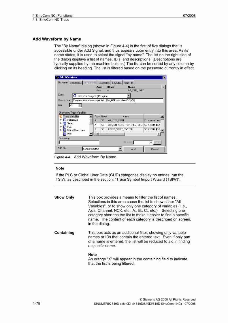
4 SinuCom NC: Functions 07/2008 4.8 SinuCom NC Trace
© Siemens AG 2008 All Rights Reserved 4-78 SINUMERIK 840D sl/840Di sl/ 840D/840Di/810D SinuCom (INC) - 07/2008
Add Waveform by Name The "By Name" dialog (shown in Figure 4-4) is the first of five dialogs that is accessible under Add Signal, and thus appears upon entry into this area. As its name states, it is used to select the signal "by name". The list on the right side of the dialog displays a list of names, ID’s, and descriptions. (Descriptions are typically supplied by the machine builder.) The list can be sorted by any column by clicking on its heading. The list is filtered based on the password currently in effect.
Figure 4-4 Add Waveform By Name
Note
If the PLC or Global User Data (GUD) categories display no entries, run the TSIW, as described in the section: "Trace Symbol Import Wizard (TSIW)".
Show Only This box provides a means to filter the list of names.
Selections in this area cause the list to show either "All Variables", or to show only one category of variables (i. e., Axis, Channel, NCK, etc.; A:, B:, C:, etc.). Selecting one category shortens the list to make it easier to find a specific name. The content of each category is described on screen, in the dialog.
Containing This box acts as an additional filter, showing only variable names or IDs that contain the entered text. Even if only part of a name is entered, the list will be reduced to aid in finding a specific name. Note An orange "X" will appear in the containing field to indicate that the list is being filtered.
07/2008 4 SinuCom NC: Functions 4.8 SinuCom NC Trace
© Siemens AG 2008 All Rights Reserved SINUMERIK 840D sl/840Di sl/ 840D/840Di/810D SinuCom (INC) - 07/2008 4-79
Bit Mask If the variable is an integer, this field can be used to specify
an optional Bit Mask. The signal value is AND’ed with this Bit Mask before it is displayed. After masking, all the selected bits are squeezed to the right so that the bit/bits appear to start at bit 0 (e. g. if all but bit 7 were masked, the resulting integer would have a value of either 0 or 1, not 0 or 128; if all but bits 7 and 0 were masked, the resulting integer would have a value of either 0, 1, 2 or 3 [not 0, 1, 128 or 129).
"Add To" Select with a drop-down list the window in which any new waveform appears.
Based on the name selected, other "qualifiers" may be needed to identify it as a unique entity. Fields designed to assist in this identification will appear in the upper right of the dialog as needed (in this example shown as "Tool Area", "Point Tool Off", and "TN". For instance, in Figure 4-4, above, the "Tool Area" field has a drop-down menu (not shown) that offers a list of tool areas from which to select. Often the selection from drop-down menu is self-explanatory, such as the case of the "Tool Area" field described above. Occasionally, however, the selection of a name will cause a field labeled "See DocOnCD" to appear. In these cases, the information required is very specific to the variable (e. g., the selection of an array index or an override). The detailed information needed to correctly select the entry can be found in DocOnCD under the name being configured.
Add Waveform by Address The "By Address" tab (shown Figure 4-4) represents the second of five dialogs that is accessible under Add Signal. Rather than selecting by name, the signal can be identified by a PLC address or a BTSS path specification.
Note
Access to this page is password-restricted.
There are two tabs on the "By Address" screen. "PLC Address" is the first tab, and is thus the default dialog when the "By Address" option is selected. Entries in the following fields are required to identify a specific address: Memory Range One of the following memory areas must be selected:
1. Input area 2. Output area 3. Bit memory area 4. Data block
Offset The specified offset is added to the starting address of the Memory Range.The resultant sum is the address of the selected variable.
4 SinuCom NC: Functions 07/2008 4.8 SinuCom NC Trace
© Siemens AG 2008 All Rights Reserved 4-80 SINUMERIK 840D sl/840Di sl/ 840D/840Di/810D SinuCom (INC) - 07/2008
Data Type One of the following data types must be selected:
1. Character 2. Byte 3. Boolean 4. Integer 5. Word 6. Double Integer 7. Double Word 8. Real The memory location which is identified by the Memory Range and Offset will be interpreted as the identified Data Type.
Waveforms can also be identified by "BTSS Address". BTSS is an addressing scheme that is proprietary to Sinumerik. A high level of proficiency is required to use this method to identify signals. Information on the structure of BTSS addresses can be found elsewhere in Sinumerik documentation.
Add Waveform by Function Add Signal by Function will be implemented in a future release. It is not available at this time.
Add Waveform – "Event Only" Signals can be added by "Event-Only". This is the special case where no data is recorded. (I. e., only the occurrence of the event is recorded.) Identification of the Event is all that is required to effect this type of recording. The choices in the drop-down menu are the same as the items in the section: "Overview: How Trace is Used", "List of Events".
Add Waveform – Favorites When this tab is clicked, a list of the most recently used Event / Data combinations will be displayed for selection. A maximum of 20 signals are retained in the list. Unless marked as a "favorite", the oldest signal is dropped when a new signal is added. The following buttons are provided: Add to Favorites
This button marks the highlighted signal with "***" in the "Favorite" column. The entry will then be kept in the list even if it has not been used recently.
Remove
This button removes the highlighted entry from the Recently Used List.
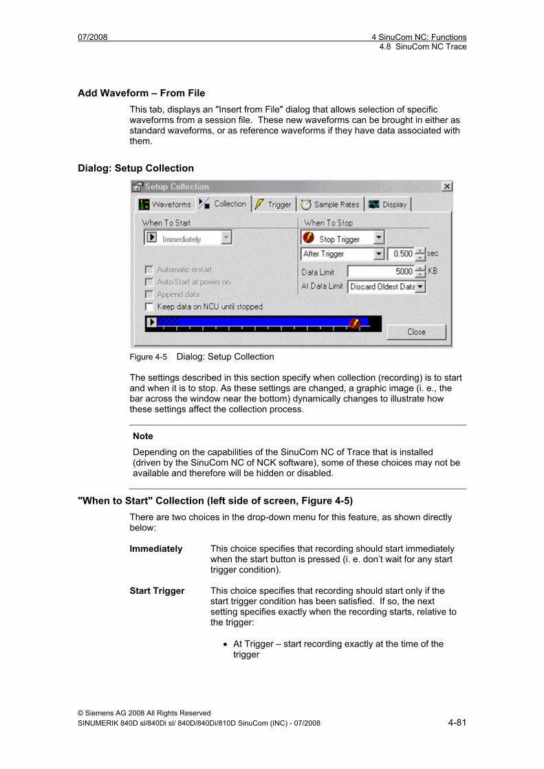
07/2008 4 SinuCom NC: Functions 4.8 SinuCom NC Trace
© Siemens AG 2008 All Rights Reserved SINUMERIK 840D sl/840Di sl/ 840D/840Di/810D SinuCom (INC) - 07/2008 4-81
Add Waveform – From File This tab, displays an "Insert from File" dialog that allows selection of specific waveforms from a session file. These new waveforms can be brought in either as standard waveforms, or as reference waveforms if they have data associated with them.
Dialog: Setup Collection
Figure 4-5 Dialog: Setup Collection The settings described in this section specify when collection (recording) is to start and when it is to stop. As these settings are changed, a graphic image (i. e., the bar across the window near the bottom) dynamically changes to illustrate how these settings affect the collection process.
Note
Depending on the capabilities of the SinuCom NC of Trace that is installed (driven by the SinuCom NC of NCK software), some of these choices may not be available and therefore will be hidden or disabled.
"When to Start" Collection (left side of screen, Figure 4-5) There are two choices in the drop-down menu for this feature, as shown directly below: Immediately
This choice specifies that recording should start immediately when the start button is pressed (i. e. don’t wait for any start trigger condition).
Start Trigger
This choice specifies that recording should start only if the start trigger condition has been satisfied. If so, the next setting specifies exactly when the recording starts, relative to the trigger:
• At Trigger – start recording exactly at the time of the trigger
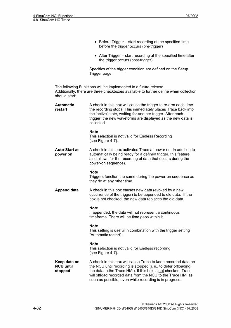
4 SinuCom NC: Functions 07/2008 4.8 SinuCom NC Trace
© Siemens AG 2008 All Rights Reserved 4-82 SINUMERIK 840D sl/840Di sl/ 840D/840Di/810D SinuCom (INC) - 07/2008
• Before Trigger – start recording at the specified time
before the trigger occurs (pre-trigger) • After Trigger – start recording at the specified time after
the trigger occurs (post-trigger) Specifics of the trigger condition are defined on the Setup Trigger page.
The following Funktions will be implemented in a future release. Additionally, there are three checkboxes available to further define when collection should start: Automatic restart
A check in this box will cause the trigger to re-arm each time the recording stops. This immediately places Trace back into the 'active' state, waiting for another trigger. After each trigger, the new waveforms are displayed as the new data is collected. Note This selection is not valid for Endless Recording (see Figure 4-7).
Auto-Start at power on
A check in this box activates Trace at power on. In addition to automatically being ready for a defined trigger, this feature also allows for the recording of data that occurs during the power-on sequence). Note Triggers function the same during the power-on sequence as they do at any other time.
Append data
A check in this box causes new data (evoked by a new occurrence of the trigger) to be appended to old data. If the box is not checked, the new data replaces the old data. Note If appended, the data will not represent a continuous timeframe. There will be time gaps within it. Note This setting is useful in combination with the trigger setting “Automatic restart“. Note This selection is not valid for Endless recording (see Figure 4-7).
Keep data on NCU until stopped
A check in this box will cause Trace to keep recorded data on the NCU until recording is stopped (i. e., to defer offloading the data to the Trace HMI). If this box is not checked, Trace will offload recorded data from the NCU to the Trace HMI as soon as possible, even while recording is in progress.
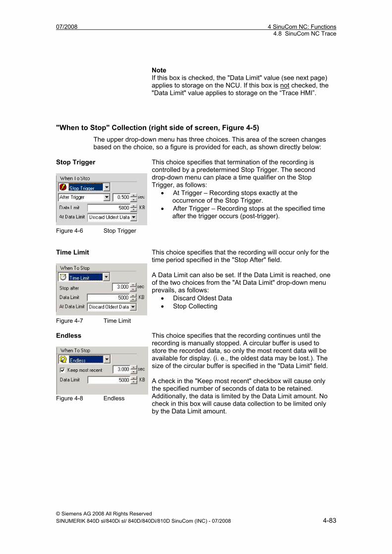
07/2008 4 SinuCom NC: Functions 4.8 SinuCom NC Trace
© Siemens AG 2008 All Rights Reserved SINUMERIK 840D sl/840Di sl/ 840D/840Di/810D SinuCom (INC) - 07/2008 4-83
Note If this box is checked, the "Data Limit" value (see next page) applies to storage on the NCU. If this box is not checked, the "Data Limit" value applies to storage on the “Trace HMI”.
"When to Stop" Collection (right side of screen, Figure 4-5) The upper drop-down menu has three choices. This area of the screen changes based on the choice, so a figure is provided for each, as shown directly below:
Stop Trigger
Figure 4-6 Stop Trigger
This choice specifies that termination of the recording is controlled by a predetermined Stop Trigger. The second drop-down menu can place a time qualifier on the Stop Trigger, as follows:
• At Trigger – Recording stops exactly at the occurrence of the Stop Trigger.
• After Trigger – Recording stops at the specified time after the trigger occurs (post-trigger).
Time Limit
Figure 4-7 Time Limit
This choice specifies that the recording will occur only for the time period specified in the "Stop After" field. A Data Limit can also be set. If the Data Limit is reached, one of the two choices from the "At Data Limit" drop-down menu prevails, as follows:
• Discard Oldest Data • Stop Collecting
Endless
Figure 4-8 Endless
This choice specifies that the recording continues until the recording is manually stopped. A circular buffer is used to store the recorded data, so only the most recent data will be available for display. (i. e., the oldest data may be lost.). The size of the circular buffer is specified in the "Data Limit" field. A check in the "Keep most recent" checkbox will cause only the specified number of seconds of data to be retained. Additionally, the data is limited by the Data Limit amount. No check in this box will cause data collection to be limited only by the Data Limit amount.
4 SinuCom NC: Functions 07/2008 4.8 SinuCom NC Trace
© Siemens AG 2008 All Rights Reserved 4-84 SINUMERIK 840D sl/840Di sl/ 840D/840Di/810D SinuCom (INC) - 07/2008
Dialog: Setup Trigger The settings described in this section define the characteristics of the trigger. If the use of triggers is specified on the Setup Collection page, there is either a stop trigger, a start trigger or both. These triggers apply to all recording within a given session. If no triggers are specified on the Setup Collection page, this Setup Trigger page is not used (and is not available). Start Trigger/ Stop Trigger
This pair of buttons can optionally be present. Two conditions are possible:
• Buttons present - Both a start and a stop trigger have been specified. Selection is mutually exclusive. On-screen data switches with the selection.
• Buttons not present - Either a start or a stop trigger has been specified. The data applies to the specified trigger.
Note As described above, if there are no triggers, the window in (see Figure 4-8) above will not appear.
Trigger Waveform
This setting specifies which signal will be used in the makeup of the trigger. The following selections are available:
• No trigger (i. e., field is left blank). • Names of waveforms already defined for collection
(can be accessed via drop-down menu).
Trigger Mode This setting specifies the type of test to be performed on the
trigger waveform. The following selections are available: • Rising edge1 – Recording begins or ends when the
trigger transitions from lower to higher than the trigger level.
• Falling edge1 – Recording begins or ends when the trigger transitions from higher to lower than the trigger level.
• Equals – Recording begins when the trigger is equal to the trigger level.
• Not equal to –Recording begins when the trigger is not equal to the trigger level.
• Greater than or equal – Recording begins when the trigger is greater than or equal to the trigger level.
• Less than or equal – Recording begins when the trigger is less than or equal to the trigger level.
• Value changed1 – Recording begins when the trigger changes from what it was at the start of recording.
1 These functions will not appear if the installed NCK SinuCom NC does not support them.
07/2008 4 SinuCom NC: Functions 4.8 SinuCom NC Trace
© Siemens AG 2008 All Rights Reserved SINUMERIK 840D sl/840Di sl/ 840D/840Di/810D SinuCom (INC) - 07/2008 4-85
Trigger Level This setting specifies the trigger waveform threshold that is
tested by the Trigger Mode.
Dialog: Setup Sample Rates Some events are cyclic in nature. (see the section: "Overview: How Trace is Used", "List of Events"). They appear in the "Setup Sample Rates" dialog. This dialog allows a multiplier, or "skip count", to be applied to each of these events to reduce their associated sampling rates (or, stated another way, increase their intervals). The multipliers must be positive whole numbers.
Note
Sometimes after a session file is loaded, the sample rate parameters specified in the newly-loaded session file cannot be realized with the current Basic Interval of the NCU. In this case, a text message in red letters will appear on the "Setup Sample Rates" dialog to indicate that the sample rates have been adjusted to numbers that can be realized. In this condition, a button on the dialog can be selected to acknowledge this adjustment and dismiss the warning message.
Dialog: Setup Display This dialog allows the visual characteristics of the waveform display to be configured.
Note
The effects of the changes are immediately reflected in the waveform display.
Note
Unlike other tabbed pages of the Setup dialog, these settings (except "Colors...") apply to each graph window independent of other graph windows.
4 SinuCom NC: Functions 07/2008 4.8 SinuCom NC Trace
© Siemens AG 2008 All Rights Reserved 4-86 SINUMERIK 840D sl/840Di sl/ 840D/840Di/810D SinuCom (INC) - 07/2008
Rename/Select Graph
This setting selects the graph window to which the display settings are applied. The Graph Window name can also be modified from this dialog. Note This field is not visible if only one Graph Window is present.
Waveform Tabs
This setting specifies the markings on the waveform tabs. The choices are: 1. Show Text - The complete text description / name of the
waveform. 2. Show Numbers - The number of the waveform. 3. Show Both. Note It may be preferable to show the text name if there are only a few signals; conversely, to reduce clutter, it may be preferable to show only the number if there are many signals.
Colors…
This button calls up "Graph Window Colors" dialog. Through its use, the colors of the following components of the graph window may be changed:
• Background color. • Grid lines color (major and minor). • Axis labels color.
To change the color of one of these items, click the "Select" button adjacent to it. A standard color selection dialog will appear. The desired waveform color can be defined by simple selection, or custom colors can be defined using the associated button.
Scaling (both X and Y Axes)
These settings determine the type of scaling for the graphs' axes. The choices are:
• Linear scaling • Logarithmic scaling
Note Logarithmic scaling is not allowed for the X axis if Graph Style is “Y vs. Time”.
Grid Lines (both X and Y Axes)
A check in one or both of these boxes determines if either the horizontal grid lines, vertical grid lines, or both, are visible.
07/2008 4 SinuCom NC: Functions 4.8 SinuCom NC Trace
© Siemens AG 2008 All Rights Reserved SINUMERIK 840D sl/840Di sl/ 840D/840Di/810D SinuCom (INC) - 07/2008 4-87
Measurement Cursor Accurate values of sampled data points can be determined through the use of the Measurement Cursor. This cursor can be added or removed from the waveform display either through the View Menu (as described in the section: "Toolbars and Menus", "Menu: View") or through its icon (Figure 4-3). The numeric readout on the toolbar reflects the X and Y positions of the selected sample point on the active waveform. The cursor can be dragged to a desired sample point, or can be incrementally moved from point to point using the arrows on the Measurement Cursor toolbar.
Difference Cursors The difference cursors are a pair of cursors that provides a function similar to the Measurement Cursor. But instead of just one position, these are two cursors that show two X and two Y positions, as well as the difference between them. The position and difference information is displayed in a dialog that is visible whenever the Difference Cursors are turned on. The cursors can be attached to the same waveform or to different waveforms. The waveform association is made within the dialog by first expanding the dialog with
the button and then choosing the waveforms from a dropdown list of waveform descriptions.
4 SinuCom NC: Functions 07/2008 4.8 SinuCom NC Trace
© Siemens AG 2008 All Rights Reserved 4-88 SINUMERIK 840D sl/840Di sl/ 840D/840Di/810D SinuCom (INC) - 07/2008
4.8.7 Trace Symbol Import Wizard (TSIW)
Note
GUD and OEM PLC symbols are not available to SinuCom NC Trace until the TSIW is run. SinuCom NC Trace adds selected symbols to the database when this wizard finishes. These symbols are also automatically imported on any subsequent installations of SinuCom NC Trace. As with any subsequent use of the TSIW, this update of symbols can take several minutes.
Previous releases of SinuCom NC Trace use a static symbols database (i. e., the set of variables that can be plotted). This database simply shipped with the system. The TSIW offers the ability to update this database at any time with a variety of symbol types from the machine environment. This data does not have to be coincident with an NCK release, but instead might be part of a PLC release, or be provided by an OEM installation. Such data includes: Global User Data (GUD): Symbols specified by multiple providers. Categories include: • System GUDs – Provided by Siemens. • OEM GUDs – Provided by a machine manufacturer. • User GUDs – Provided for a part program or specific factory floor application. • GUD 4 – 9: Available for special purposes. PLC VDI Symbols – Names of PLC data created by Siemens and shipped with a SinuCom NC of the PLC software.
Note
A set of PLC VDI symbols ships with SinuCom NC. A special procedure must be performed to update these. (See "How to Make Symbols Available for Import"
PLC OEM Symbols – Names of PLC data created for a particular machine application by a machine manufacturer.
Note
Local User Data (LUD) and Program User Data (PUD) are temporary variables created by a part program or a subprogram. The NCK creates this data at the request of a part program and removes it when the program terminates. The TSIW does not address this type of data.
07/2008 4 SinuCom NC: Functions 4.8 SinuCom NC Trace
© Siemens AG 2008 All Rights Reserved SINUMERIK 840D sl/840Di sl/ 840D/840Di/810D SinuCom (INC) - 07/2008 4-89
How To Make Symbols Available for Import Before using the TSIW, certain types of symbols must be staged for import, as described below: GUDs: Nothing needs to be done for these symbols. The machine environment either has them available or it doesn’t. PLC Symbols (OEM or VDI): This 2-step procedure must be performed only once, prior to first use of SIMATIC Manager. It installs the SIMATIC Manager toolbox. If this procedure has already been performed, please skip to the next appropriate section.
Note
If the toolbox installer has been downloaded, start the downloaded file. (It may be called 07010100.exe). This creates a folder that contains the setup.exe program.
1. Using the PG/PC, call up PLC Toolbox Setup. 2. Under "Programs to be installed":
• click "PLC Basic Program for <control> Vv.w", and • click "SINUMERIK Add-on for STEP 7 Vx.y".
3. Click “Next>”, then continue with the procedure directly below. Exporting the PLC Input/Output/Bit Memory Symbols from SIMATIC: 1. From the Windows® desktop, launch the SIMATIC Manager by selecting
"Start", "Programs", "SIMATIC", then "SIMATIC Manager"
2. Press "Cancel" to dismiss the "New Project Wizard".
3. From the SIMATIC Manager's File menu, select "Open..."
4. When the "Open Project" dialog appears, select the "Libraries" tab
5. From the list, select "gp8x0d“. A list of objects will appear in the window on the right.
6. Double-click the object named "Symbols“.
7. From the window that appears select "Export“ from the Symbol Table menu.
8. From the dialog that appears, select a folder (recommended folder: c:\siemens\sinumerik\symbols: [default for SIMATIC symbols export]).
9. Provide a filename
10. Click "Save".
11. Proceed to one of the two following procedures on the next two pages.
4 SinuCom NC: Functions 07/2008 4.8 SinuCom NC Trace
© Siemens AG 2008 All Rights Reserved 4-90 SINUMERIK 840D sl/840Di sl/ 840D/840Di/810D SinuCom (INC) - 07/2008
Updating PLC VDI Symbols: Avoid this procedure unless you have installed the 810D sl/ 840D(i) Toolbox (SinuCom NC 07.01 and newer). This procedure will take several minutes in the TSIW, and several minutes of additional time in SinuCom NC Trace after the TSIW completes. After performing the procedure for PLC Symbols on the previous page, these symbols can be prepared for export from the machine environment via the following procedure:
! Caution
The two procedures on the preceding page must have been performed or this procedure will fail.
1. From the Windows® desktop, launch the SIMATIC Manager by selecting
"Start", "Programs", "SIMATIC", then "SIMATIC Manager".
2. From the SIMATIC Manager's File menu, select "Open...".
3. When the "Open Project" dialog appears, select the "Libraries" tab.
4. Select the library named "gp8x0d64" (or other desired library SinuCom NC [ex: gp8x0d71]), then press "OK". A new dialog with a project tree on the left will appear.
5. From the project tree, select "Sources".
6. Right-click the object named "nst_udtb". (This is the object that contains the PLC VDI symbols.)
7. From the context menu that appears, select "Export Source...".
8. Select the c:\siemens\sinumerik\symbols folder in which to save nst_udtb.AWL (English) or nst_udt.AWL (German). Note this location, since the TSIW will be set up to search here for the PLC VDI symbols.
9. Click "Save". The PLC VDI Symbols are now ready for import. Updating PLC OEM Symbols: After performing the procedure for PLC Symbols on the previous page, these symbols can be prepared for export from the machine environment via the following procedure:
! Caution
The two procedures on the preceding page must have been performed or this procedure will fail.
07/2008 4 SinuCom NC: Functions 4.8 SinuCom NC Trace
© Siemens AG 2008 All Rights Reserved SINUMERIK 840D sl/840Di sl/ 840D/840Di/810D SinuCom (INC) - 07/2008 4-91
1. From the Windows® desktop, launch the SIMATIC Manager by selecting
"Start", "Programs", "SIMATIC", then "SIMATIC Manager".
2. In the SIMATIC Manager application, select "File", "Open", and then select the desired PLC project.
3. Double-click the compiled logic block for which you wish to export Trace symbols.
4. From the LAD editor ("LAD, FBD – Programming S7 Blocks.") select "File", "Generate Source" from the File menu. The new dialog will appear.
5. In the "Object Name" box, key in the name of the source file that will contain the desired PLC OEM symbols, then press "OK".
6. The "Generate source <object>" dialog will appear.
7. Highlight the blocks in the "Blocks Not Selected" window that contain the symbols to be imported, then use the right arrow to move these blocks to the "Blocks Selected" window. Make sure the "Symbolic" option is selected.
8. Activate the SIMATIC Manager (click on it).
9. From the project tree, select "Sources".
10. Right-Click the new Source file in the list.
11. From the menu that appears, select "Export Source...".
12. Select the c:\siemens\sinumerik\symbols folder.
13. Click "Save". The PLC OEM Symbols are now ready for import.
Importing the Symbols Once symbols are prepared for import (as described above) the Trace Symbol Import Wizard can be invoked from SinuCom NC through the following procedure: 1. If SinuCom NC Trace is not already running, start Trace from SinuCom NC (as
described in "A Hands-On Example").
2. Select "File" from the main menu.
3. Select "Import Symbols...". The Overview screen will appear, indicating if any symbols now exist in the NC that have not yet been imported into SinuCom NC.
4. Select “Next>”. The user is then asked if a Custom or an Express Import is to be performed.
5. Select "Express Import".
4 SinuCom NC: Functions 07/2008 4.8 SinuCom NC Trace
© Siemens AG 2008 All Rights Reserved 4-92 SINUMERIK 840D sl/840Di sl/ 840D/840Di/810D SinuCom (INC) - 07/2008
6. For PLC symbols, the "Include PLC Symbols" check is made available by typing the name of the PLC folder (only if the symbols are located in a folder othere than the default). Typing an invalid folder or one with no symbols invalidates the "Include PLC Symbols check box.
7. Click Finish
8. When the procedure completes the wizard disappears. The new symbols are now available for use in SinuCom NC Trace.
Express versus Custom Import
Note
An Express Import is recommended to reduce the complexity of this procedure.
Express Import: Prepares the wizard to accept all default selections, and to import PLC symbols from the specified folder. TSIW will disable the "Include PLC symbols" checkbox if the folder specification is incorrect or the folder does not contain the required symbol files (reference "How to Make Symbols Available for Import"). The "Browse" button can be used to correct the folder specification. Clicking the "Finish" button proceeds directly to the Summary screen and starts the import process. However if there is nothing for the Wizard to do, only the Cancel button will be available. Custom Import: Allows to decide whether to import GUDs and which kind of PLC symbols to import. This is only recommended for users who need a greater degree of control over what symbols are added into the database. Clicking the “Next>” button advances the dialog to Global User Data. The following screens apply only to the "Custom" selection:
• Global User Data • PLC Variables
Global User Data If there are GUDs available for import, this selection on the left of the screen is active. Selecting it yields a list of any GUDs available for import (if any). (Note that the wizard will display only GUD categories with defined GUDs. For example when there are no GUDs in a category, the category is skipped) Each GUD displayed might have available GUDs for "Channel", "General", both or neither.
07/2008 4 SinuCom NC: Functions 4.8 SinuCom NC Trace
© Siemens AG 2008 All Rights Reserved SINUMERIK 840D sl/840Di sl/ 840D/840Di/810D SinuCom (INC) - 07/2008 4-93
PLC Variables
Note
Typically PLC VDI symbols are already installed. The mention of PLC VDI symbols only applies when a SinuCom NC update is required.
If there are either PLC VDI or PLC OEM variables available for import, the "PLC Variables" selection on the left of the screen is active. Import of these two variable types is identical. Thus, they are loaded at the same time with the same tool. In addition to allows user to select a pertinent folder or project file (first two buttons), the following selections it allows to specify the types of symbols to be imported:
Note
The following choices appear on the "General" tab: • Import I, Q, M symbols • Import User DB symbols
When you prepare VDI Symbols for upgrade, the "Advanced" tab becomes available. Using this tab requires prior selection of Import I, Q, M symbols. Clicking the "Advanced" tab reveals the following additional choice:
• Import PLC-NC Interface (VDI) symbols. After the choices above have been made, any new PLC variables available for import are displayed. Summary Screen Prior to exiting the TSIW, the Summary Screen confirms the choice of symbols for import, and displays progress as it creates the database files to be used by SinuCom NC Trace. When importing activities complete, the TSIW dismisses itself.
4 SinuCom NC: Functions 07/2008 4.8 SinuCom NC Trace
© Siemens AG 2008 All Rights Reserved 4-94 SINUMERIK 840D sl/840Di sl/ 840D/840Di/810D SinuCom (INC) - 07/2008
4.8.8 Trace Setup Wizard (TSW) SINUMERIK 840D Trace must be properly configured to support SinuCom NC Trace and the SI Acceptance Test. The TSW provides two choices for configuration:
• EXPRESS (to minimize the required steps, yet still provide a typical configuration).
• CUSTOM (for experts, who wish to fine tune the configuration). If a message box suggesting use of the TSW appears at startup, an unsuitable configuration is present. The TSW must be run in this case.
Note
A startup check is performed by SinuCom NC Trace (Trace) and SI Acceptance Test for minimum Trace resources. A message box appears if this test fails. If this occurs, use the Trace Setup Wizard (TSW) to configure the Trace applications that you want to run. After successfully running the TSW, SinuCom NC Trace applications will start up without interruption.
To start the TSW from the SinuCom NC opening screen: 1. Select "Open Online Project" from its toolbar button or the "Target Syst."
menu. 2. Expand the Sinumerik folder and double-click on the machine data block
(e. g., "MD-block 1"). Ensure that the "Display Dialog" (not the Expert List) is active.
3. Click on "Trace Setup Wizard" in the project tree.
Overview Dialog The Overview Dialog is the opening screen for the TSW. It describes the current state of the system’s Trace Server and NCK configuration according to the selected trace applications. This shows whether the currently configured trace applications are consistent with the current NCK configuration and NCK SinuCom NC. The Overview displays the connected NCK’s name, SinuCom NC number, and current SRAM and DRAM utilization. The Overview also shows the status of each configured application. A green check mark ( ) icon indicates that the current configuration supports the running of this application. A red "X" means that this application cannot run with the current configuration. Along with the red "X", a “Results” button appears. Pressing this button describes why the application won’t run with the current configuration.
07/2008 4 SinuCom NC: Functions 4.8 SinuCom NC Trace
© Siemens AG 2008 All Rights Reserved SINUMERIK 840D sl/840Di sl/ 840D/840Di/810D SinuCom (INC) - 07/2008 4-95
Setup Method Dialog
Note
Express Setup is recommended to reduce the complexity of this procedure.
Express: Prepares the wizard to accept all default selections. Clicking the "Finish" button proceeds directly to the Summary screen and starts the setup process. However, if the Wizard finds nothing to do, only the Cancel button will be available. Custom: Allows users to decide whether to provide specific values for resource allocations. This is only recommended for users who want a greater degree of control over the settings for individual trace application. Clicking the “Next>” button proceeds to the applications list. The following screens are available only in Custom Setup mode:
• Trace Applications List. • SinuCom NC Trace • Generic Trace Client • Advanced Features
Trace Applications List
Note
Warning text indicates if an earlier NCK SinuCom NC will not allow the SI Acceptance Test to run.
The Trace Applications List provides information to balance the available trace resources among the SinuCom NC applications. Therefore, it is best not to click "Yes" for an application unless you have a known need to run it. There is also a choice between sharing slots or configuring multiple slots. Each allocated slot corresponds to a resource that hosts a trace recording session. SI Acceptance Test uses only one recording session, but SinuCom NC trace can use more than one recording session. SinuCom NC Trace can start a recording session and switch to another. Simultaneous use of multiple trace recording sessions is an advanced feature. Slot allocation selections are:
• One shared slot for all applications. (This is only choice for earlier NCK SinuCom NCs.)
• Multiple slots to be shared for all applications.
Note
A configuration page is provided for Trace and Generic applications. Generic applications are optional and are not available in most cases.
4 SinuCom NC: Functions 07/2008 4.8 SinuCom NC Trace
© Siemens AG 2008 All Rights Reserved 4-96 SINUMERIK 840D sl/840Di sl/ 840D/840Di/810D SinuCom (INC) - 07/2008
Note
A configuration page is not presented for the SI Acceptance Test because its requirements are fixed.
Common General Configuration Items These items are available for fine tuning SinuCom NC Trace and Generic applications. Please avoid changing these values unless you need to customize your settings. The Summary section can be skipped if performing an "Express Setup“.
• Maximum simultaneous sessions: Total user slots required by this application. Slots should be used sparingly to avoid impairing other control functions.
• Maximum standard unique data lists: (memory) Total standard events. Each combination of a different standard event and NCK data item requires one list. Reference: MD 18371, MM_PROTOC_NUM_ETPD_STD_LST.
• Highest standard event ID: (memory) highest event number used. Normally all standard events should be included. Reference: MD 28302, MM_PROTOC_NUM_ETP_STD_TYP.
• Maximum OEM unique data lists: (memory) Total OEM events. Each combination of a different OEM event and NCK data item requires one list. Reference MD 18372, MM_PROTOC_NUM_ETPD_OEM_LST.
• Highest OEM event ID: (memory) Highest NCK OEM event number. Reference: MD 28301, MM_PROTOC_NUM_ETP_STD_TYP.
• Maximum simultaneous servo signals: (memory) Total servo data items per session. Reference: MD 18373, MM_PROTOC_NUM_SERVO_DATA.
Common Advanced Configuration Items
• Amount of data stored in the NCU SRAM/DRAM log file: Maximum file size for the NCK log file. Data loss occurs when the logged data exceeds this size prior to being offloaded to the HMI. Corresponds with TraceSrv.ini key nckFileSize. Note deferred offloading overrides this size with the value specified for a Trace.
• Amount of data stored in the HMI hard drive log file: Maximum size for the log file offloaded to the HMI’s hard drive. If the session’s total amount of data logged exceeds this size (without a client consuming the data), data loss occurs. Corresponds with TraceSrv.ini key "HmiFileCapacity". Note If a session disables deferred offloading, the size in the session overrides this.
• Amount of data cached to the HMI RAM Frame: Maximum data memory for logging that is cached for quick client access on the HMI. This allocation uses the OS virtual memory pool, and thereby affects other applications running on the CPU. Corresponds with TraceSrv.ini key "HmiFrameCapacity".
07/2008 4 SinuCom NC: Functions 4.8 SinuCom NC Trace
© Siemens AG 2008 All Rights Reserved SINUMERIK 840D sl/840Di sl/ 840D/840Di/810D SinuCom (INC) - 07/2008 4-97
• Size of the NCK Trace Logging Buffer: Size of the FIFO buffer on the NCK that spools captured data to the NCK Log File. Determines the memory resource allocation on the NCK. Decreasing the size can cause data loss. Reference: MD 18374, MM_PROTOC_FILE_BUFFER_SIZE.
• Type of NCK Memory used for log data file: Selects SRAM or DRAM for the NCK Trace log file. Reference: MD 11295, PROTOC_FILE_MEM.
SinuCom NC Trace SinuCom NC Trace has requirements that vary with each session. A minimal resource allocation is provided by default
Generic Trace Client The Generic Trace Client does not appear in most installations. If it does appear, there are a few unique configuration details:
• Application Name: Text string user name displayed for generic trace application.
• Generic Trace Client Name: Text string representing the key used to
identify the application in the TraceSrv.ini file.
Advanced Features The Trace Setup Wizard advanced features page provides entries for expert configuration of Trace services. Some items represent resources that are shared by multiple applications. For these items, the current values and the required values are displayed. The user can override the required values or accept the calculated value.
• Amount of data storage in the NCU SRAM/DRAM Log: Maximum file size for the NCK log file. Data loss occurs when the logged data exceeds this size prior to being offloaded to the HMI. Corresponds with TraceSrv.ini key nckFileSize. Note deferred offloading replaces this size with the value specified for a Trace.
• Amount of data stored in the HMI hard drive log file: Maximum size for the log file offloaded to the HMI’s hard drive. If the session’s total amount of data logged exceeds this size (without a client consuming the data), data loss occurs. Corresponds with TraceSrv.ini key HmiFileCapacity.
• Amount of data cached to the HMI RAM Frame: Maximum data memory for logging that is cached for quick client access on the HMI. This allocation uses the OS virtual memory pool, and thereby affects other applications running on the CPU. Corresponds with TraceSrv.ini key HmiFrameCapacity.
• Required User Slots: The number of NCK Trace user slots required to support the currently configured applications. If the slot range is not correctly specified a session may not be hosted by the NCK because of slot limitations.
• Lowest valid trace user slot: This is the lowest user slot that can be reserved by the Trace Server for use. Corresponds with TraceSrv.ini key LowestUserSlot.
4 SinuCom NC: Functions 07/2008 4.8 SinuCom NC Trace
© Siemens AG 2008 All Rights Reserved 4-98 SINUMERIK 840D sl/840Di sl/ 840D/840Di/810D SinuCom (INC) - 07/2008
Note 1
This item, in conjunction with the highest user slot, determines the valid range of NCK Trace user slots available for use by the Trace Server and its client applications.
Note 2
User slots 1,2, and 3 are reserved for use by Siemens applications.
• Highest valid trace user slot: Highest user slot that can be reserved for
use. Corresponds with TraceSrv.ini key HighestUserSlot. • Trace Server stays alive when no client exists: Prevents the Trace Server
from shutting down when no client applications are running. Corresponds with TraceSrv.ini key KeepTraceSrvAlive.
Note
If the Trace Server is kept running, only system shutdown will terminate the server. This may present problems if other HMI Base servers are terminated.
• Maintain NCU Trace diagnostic file: Causes the Trace Server to create and
maintain an NCK Trace Diagnostic file on the NCK. The file: SIEMPROTOKSTATUS.MPF is maintained in the MPF directory. The diagnostic file records configuration and memory utilization data that can be used for problem diagnosis. Corresponds with TraceSrv.ini key RetainTraceDiagnosticFile. Note Feature, not currently supported.
Summary Screen The Trace Setup Wizard transitions to the summary page when the user presses the “Finish” Button. The summary page indicates progress through the configuration list with an arrow that appears next to each completed item. The process suspends if an NCK reset or NCK memory archive is required. Continue the process by pressing the "Execute..." button on the SinuComNC tool bar. When setup activities complete, the TSW returns to the Overview Dialog.
07/2008 4 SinuCom NC: Functions 4.9 Safety Integrated Acceptance Test Wizard
© Siemens AG 2008 All Rights Reserved SINUMERIK 840D sl/840Di sl/ 840D/840Di/810D SinuCom (INC) - 07/2008 4-99
4.9 Safety Integrated Acceptance Test Wizard
Background and Definitions EC Machine Directive requires the original equipment manufacturer (OEM) to: • run acceptance testing on safety-relevant functions and machine parts. • generate an "Acceptance Test Certificate" showing the test results. The Safety Integrated Acceptance Test Wizard ("SI Wizard") is a "front end" designed to accomplish the above tasks. It eases the work of the OEM by: • Providing a standard way of adding the needed safety measures through the
use of a user interface which has the look and feel of other components within SinuCom NC.
• Minimizing the number of steps involved in performing a given test. • Integrating/automating the test instructions, test actions, collection of data and
generation of the Acceptance Test Certificate in "wizard format". • Allowing the user to determine pass/fail status of each test (i. e., the decision-
making process is not automated). • Making the test results easy to view, clear and repeat as desired.
Compatibility with Siemens Software SinuCom NC – Must be version 06.03.10 or later in power line. SinuCom NC - Must be version 07.02.01 or later in solution line. NCK – Must be version 06.04.15 or later.
Acceptance Test Certificate The Acceptance Test Certificate is generated in the same language that has been selected as the SinuCom NC UI language. It is produced as a file in Rich Text Format (RTF). RTF is a standard format compatible with many text editors, including MicroSoft Word®.
4.9.1 Example: 1. Activate SinuCom NC. 2. Click "Diagnosis" in the SinuCom NC main menu. 3. Click "SI Acceptance Test" in the Diagnosis menu. The "Introduction/ Overview"
Screen will appear.
4 SinuCom NC: Functions 07/2008 4.9 Safety Integrated Acceptance Test Wizard
© Siemens AG 2008 All Rights Reserved 4-100 SINUMERIK 840D sl/840Di sl/ 840D/840Di/810D SinuCom (INC) - 07/2008
4. Key in representative data in the fields on the right side of the screen. Entries made here describe the test environment, and will ultimately appear on the Acceptance Test Certificate. Field descriptions are as follows: • Machine designation – The machine name (e. g., "Polaris 9000"). • Machine type – The kind of machine (e. g., knee mill). • Serial number – The unique serialized number assigned to the machine
by the OEM. • Manufacturer – The machine maker, or OEM. • PLC SinuCom NC manufacturer – The manufacturer of the PLC. • Ultimate customer – The end-user of the machine. • Name of tester – The person running the test. • Series machine startup – Check if the machine is part of a production
run of similar machines. • "Safe programmable logic" – automatical setting, whether SPL existent
or inexistent.
5. Click "Functional Relationships" in the List of Tests on the left side of the screen. The "Summary Functional Relationships" screen will appear.
Note
"Functional Relationships" was chosen for this example because it is a basic type of test. It simply allows manual entry of any test, and the results of the test.
6. Click the "Begin This Test" button. The "Results New Test" screen will appear. 7. Note that a "New Test" has been added to the List of Tests under "Functional
Relationships". 8. Click the "Continue Test" button. The "Results New Test" screen is now
updated to allow tester to perform any test that is desired. The tester can manually name the test, and and can document the Test Trigger Condition and Result in the fields provided. The name given to the test now appears in the List of Tests.
9. Select "Click here if functional test valid". The test is now marked as "passed
(green check). In any other case, a red cross is displayed. 10. Click the "Finish" button near the bottom of the screen. The "Finished" screen
will appear. 11. Click the "Generate Certificate" button. Because the test suite for this example
is not complete, a prompt asking if a partial certificate will appear. 12. Click "Yes". A "Save" dialog box will appear. 13. Key in a path and filename and click the "Save" button.
07/2008 4 SinuCom NC: Functions 4.9 Safety Integrated Acceptance Test Wizard
© Siemens AG 2008 All Rights Reserved SINUMERIK 840D sl/840Di sl/ 840D/840Di/810D SinuCom (INC) - 07/2008 4-101
4.9.2 Common Screen Contents All SI Wizard screens consist of two major display regions: • A Selection/Status Pane (i. e., the List of Tests on the left) • A Dialog Pane (i. e., the area on the right).
The following features are found at the top of each screen: • The Test Title • The screen type • A prompt below the Test Title
The "Next Page", "Previous Page" and "Finish" buttons appear at the bottom left. They are useful for navigating within and among tests. Buttons for Cancel and Help appear at the bottom right.
Note
The Cancel button terminates the wizard, but may request further confirmation before termination is allowed.
The Selection/Status Pane The Selection/Status pane (left side of initial screen) has two main functions: • Display of status information pertaining to individual tests and the overall
acceptance test. • Navigation between test steps and between test results. Initially, this list contains one entry per test step with a final entry, “Finished”, used primarily for status. Tests are displayed under the appropriate test step as they are invoked. They appear in one of three states: • Enabled Tests – Tests that are appropriate for the machine type and must be
run.
• Disabled Tests – Tests that are inappropriate for the machine type and feature content and cannot be run. (I. e., tests that require Safe Programmable Logic are unavailable if that feature is not present.)
• Deselected Tests - Tests that have been specified as not applicable for the current machine configuration by the user. Tests are deselected by navigating to the individual test and then deselecting the test by checking a checkbox on the test summary screen.
As tests are performed, the list is modified to show the status of individual tests. Figure 4-9, below, is an example of the results of four tests: • “Test1” (passed, "Pulse Disable Path" step). • “Operator Door” (passed, "External Stops" step). • “Tool Chain Door” (failed, "External Stops" step). • Test 3 (Test is currenty being run)
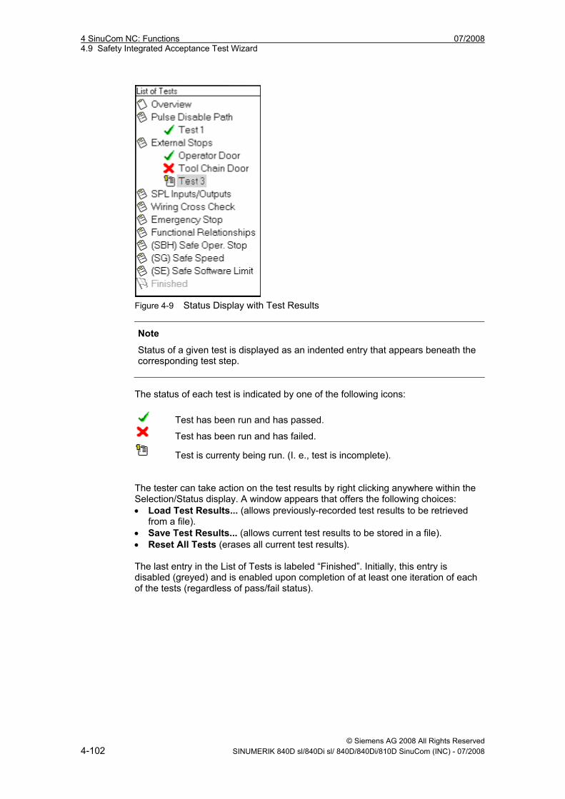
4 SinuCom NC: Functions 07/2008 4.9 Safety Integrated Acceptance Test Wizard
© Siemens AG 2008 All Rights Reserved 4-102 SINUMERIK 840D sl/840Di sl/ 840D/840Di/810D SinuCom (INC) - 07/2008
Figure 4-9 Status Display with Test Results
Note
Status of a given test is displayed as an indented entry that appears beneath the corresponding test step.
The status of each test is indicated by one of the following icons:
Test has been run and has passed.
Test has been run and has failed.
Test is currenty being run. (I. e., test is incomplete). The tester can take action on the test results by right clicking anywhere within the Selection/Status display. A window appears that offers the following choices: • Load Test Results... (allows previously-recorded test results to be retrieved
from a file). • Save Test Results... (allows current test results to be stored in a file). • Reset All Tests (erases all current test results). The last entry in the List of Tests is labeled “Finished”. Initially, this entry is disabled (greyed) and is enabled upon completion of at least one iteration of each of the tests (regardless of pass/fail status).
07/2008 4 SinuCom NC: Functions 4.9 Safety Integrated Acceptance Test Wizard
© Siemens AG 2008 All Rights Reserved SINUMERIK 840D sl/840Di sl/ 840D/840Di/810D SinuCom (INC) - 07/2008 4-103
Dialog Pane The Dialog Pane (right side of initial screen) contains interactive information that is specific to the test that has been selected in the Selection/Status Pane. Since most tests have similar operational steps (i. e., setup, induce the failure, and verify the results) each of the dialogs has generally the same operational model. Each test is typically represented by three screen types: • Test Summary Screen – Describes the purpose, procedure, and any warnings
associated with the test. Pressing the "Begin This Test" button advances the dialog to the "Running Test Screen".
• Running Test Screen – Provides a step-by-step series of prompts such as: - Establish initial conditions (e. g., select the appropriate axis) - Start the test (will also auto-start the data collection) - Terminate data collection - Select data to be saved - Restore initial conditions (usually a prompt for the operator to restore the
machine) Each step of each step has colored a number box with the following color: Green box - indicates a completed step. The user cannot progress to next step without completing the current step. Yellow box - indicates the current step. The prompt that appears in the display area at the top of the dialog applies to this step. Gray box - indicates an upcoming step. • Test Results Screen – This screen:
- Allows manual entry of the pass/fail status of the test. - Allows entry of observations for test results, if required. (Prompting that
includes the captured data from the Running Test screen may occur.). - Provides a “Repeat This Test” button at end of test, if appropriate. - Provides a “Delete Test Results” button at end of test, if appropriate.
Note
If "Repeat This Test" is selected, results from the current test are NOT discarded. (Test data is discarded only when "Delete This Test" is selected.) Repeating is appropriate when the same test is run multiple times with different commissioning (e. g., tests performed on multiple I/O points or axes.).
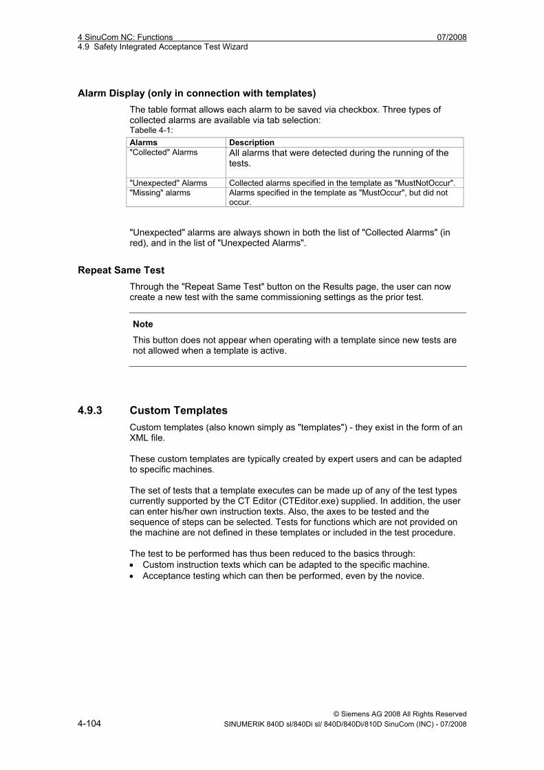
4 SinuCom NC: Functions 07/2008 4.9 Safety Integrated Acceptance Test Wizard
© Siemens AG 2008 All Rights Reserved 4-104 SINUMERIK 840D sl/840Di sl/ 840D/840Di/810D SinuCom (INC) - 07/2008
Alarm Display (only in connection with templates) The table format allows each alarm to be saved via checkbox. Three types of collected alarms are available via tab selection: Tabelle 4-1: Alarms Description "Collected" Alarms All alarms that were detected during the running of the
tests.
"Unexpected" Alarms Collected alarms specified in the template as "MustNotOccur". "Missing" alarms Alarms specified in the template as "MustOccur", but did not
occur.
"Unexpected" alarms are always shown in both the list of "Collected Alarms" (in red), and in the list of "Unexpected Alarms".
Repeat Same Test Through the "Repeat Same Test" button on the Results page, the user can now create a new test with the same commissioning settings as the prior test.
Note
This button does not appear when operating with a template since new tests are not allowed when a template is active.
4.9.3 Custom Templates Custom templates (also known simply as "templates") - they exist in the form of an XML file. These custom templates are typically created by expert users and can be adapted to specific machines. The set of tests that a template executes can be made up of any of the test types currently supported by the CT Editor (CTEditor.exe) supplied. In addition, the user can enter his/her own instruction texts. Also, the axes to be tested and the sequence of steps can be selected. Tests for functions which are not provided on the machine are not defined in these templates or included in the test procedure. The test to be performed has thus been reduced to the basics through: • Custom instruction texts which can be adapted to the specific machine. • Acceptance testing which can then be performed, even by the novice.
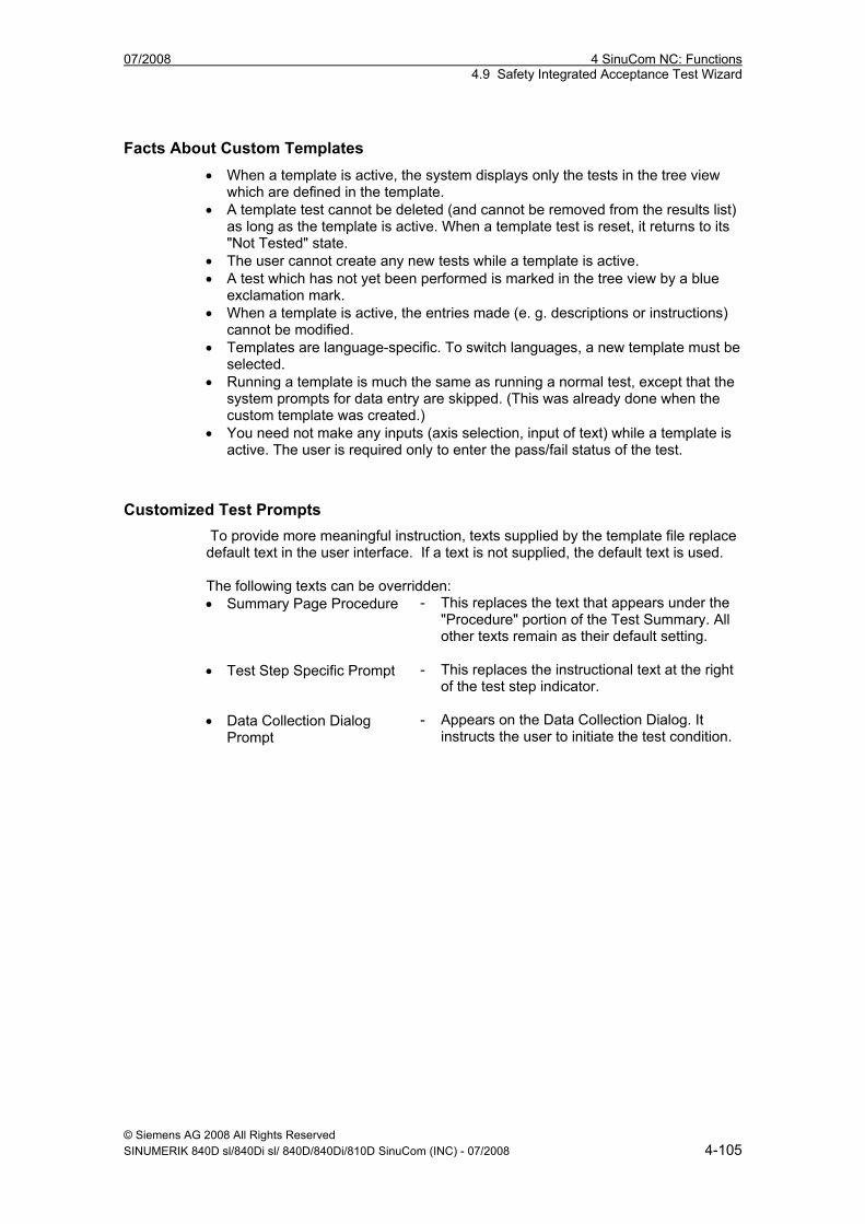
07/2008 4 SinuCom NC: Functions 4.9 Safety Integrated Acceptance Test Wizard
© Siemens AG 2008 All Rights Reserved SINUMERIK 840D sl/840Di sl/ 840D/840Di/810D SinuCom (INC) - 07/2008 4-105
Facts About Custom Templates • When a template is active, the system displays only the tests in the tree view
which are defined in the template. • A template test cannot be deleted (and cannot be removed from the results list)
as long as the template is active. When a template test is reset, it returns to its "Not Tested" state.
• The user cannot create any new tests while a template is active. • A test which has not yet been performed is marked in the tree view by a blue
exclamation mark. • When a template is active, the entries made (e. g. descriptions or instructions)
cannot be modified. • Templates are language-specific. To switch languages, a new template must be
selected. • Running a template is much the same as running a normal test, except that the
system prompts for data entry are skipped. (This was already done when the custom template was created.)
• You need not make any inputs (axis selection, input of text) while a template is active. The user is required only to enter the pass/fail status of the test.
Customized Test Prompts To provide more meaningful instruction, texts supplied by the template file replace default text in the user interface. If a text is not supplied, the default text is used. The following texts can be overridden: • Summary Page Procedure - This replaces the text that appears under the
"Procedure" portion of the Test Summary. All other texts remain as their default setting.
• Test Step Specific Prompt - This replaces the instructional text at the right of the test step indicator.
• Data Collection Dialog Prompt
- Appears on the Data Collection Dialog. It instructs the user to initiate the test condition.
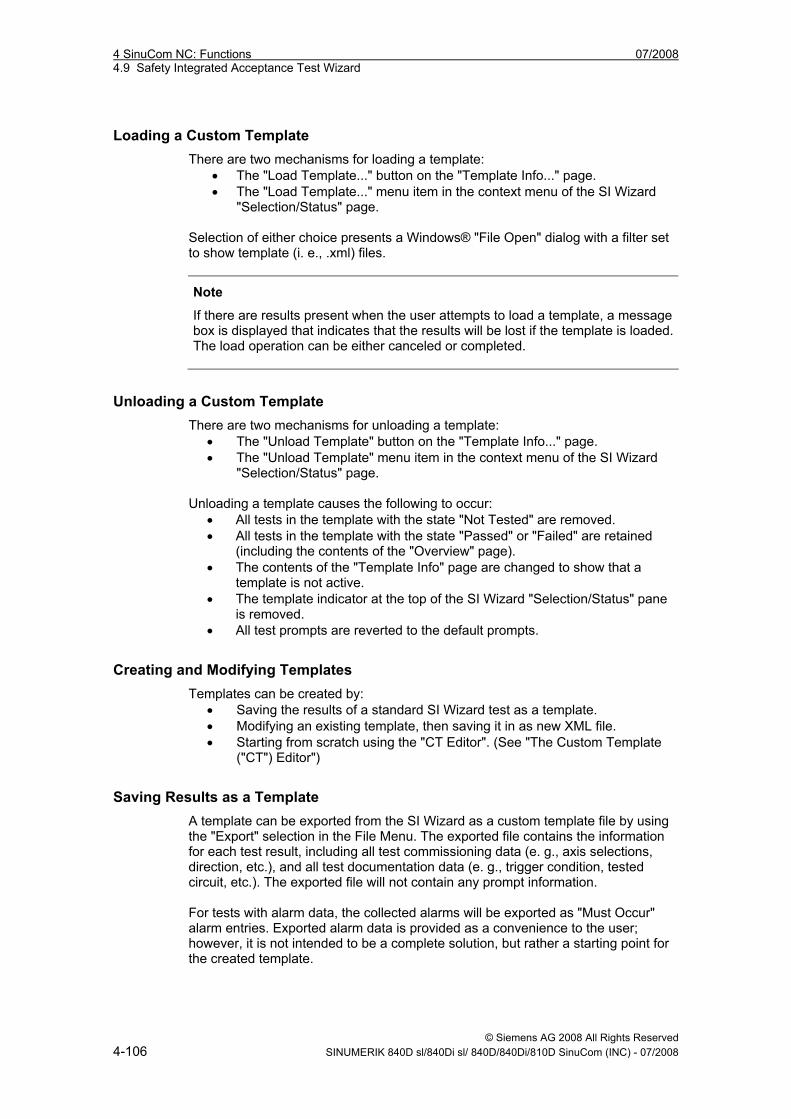
4 SinuCom NC: Functions 07/2008 4.9 Safety Integrated Acceptance Test Wizard
© Siemens AG 2008 All Rights Reserved 4-106 SINUMERIK 840D sl/840Di sl/ 840D/840Di/810D SinuCom (INC) - 07/2008
Loading a Custom Template There are two mechanisms for loading a template:
• The "Load Template..." button on the "Template Info..." page. • The "Load Template..." menu item in the context menu of the SI Wizard
"Selection/Status" page. Selection of either choice presents a Windows® "File Open" dialog with a filter set to show template (i. e., .xml) files.
Note
If there are results present when the user attempts to load a template, a message box is displayed that indicates that the results will be lost if the template is loaded. The load operation can be either canceled or completed.
Unloading a Custom Template There are two mechanisms for unloading a template:
• The "Unload Template" button on the "Template Info..." page. • The "Unload Template" menu item in the context menu of the SI Wizard
"Selection/Status" page. Unloading a template causes the following to occur:
• All tests in the template with the state "Not Tested" are removed. • All tests in the template with the state "Passed" or "Failed" are retained
(including the contents of the "Overview" page). • The contents of the "Template Info" page are changed to show that a
template is not active. • The template indicator at the top of the SI Wizard "Selection/Status" pane
is removed. • All test prompts are reverted to the default prompts.
Creating and Modifying Templates Templates can be created by:
• Saving the results of a standard SI Wizard test as a template. • Modifying an existing template, then saving it in as new XML file. • Starting from scratch using the "CT Editor". (See "The Custom Template
("CT") Editor")
Saving Results as a Template A template can be exported from the SI Wizard as a custom template file by using the "Export" selection in the File Menu. The exported file contains the information for each test result, including all test commissioning data (e. g., axis selections, direction, etc.), and all test documentation data (e. g., trigger condition, tested circuit, etc.). The exported file will not contain any prompt information. For tests with alarm data, the collected alarms will be exported as "Must Occur" alarm entries. Exported alarm data is provided as a convenience to the user; however, it is not intended to be a complete solution, but rather a starting point for the created template.
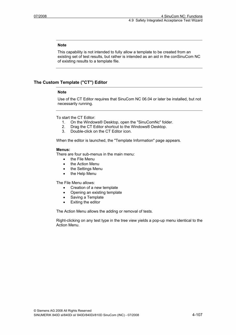
07/2008 4 SinuCom NC: Functions 4.9 Safety Integrated Acceptance Test Wizard
© Siemens AG 2008 All Rights Reserved SINUMERIK 840D sl/840Di sl/ 840D/840Di/810D SinuCom (INC) - 07/2008 4-107
Note
This capability is not intended to fully allow a template to be created from an existing set of test results, but rather is intended as an aid in the conSinuCom NC of existing results to a template file.
The Custom Template ("CT") Editor
Note
Use of the CT Editor requires that SinuCom NC 06.04 or later be installed, but not necessarily running.
To start the CT Editor:
1. On the Windows® Desktop, open the "SinuComNc" folder. 2. Drag the CT Editor shortcut to the Windows® Desktop. 3. Double-click on the CT Editor icon.
When the editor is launched, the "Template Information" page appears. Menus: There are four sub-menus in the main menu:
• the File Menu • the Action Menu • the Settings Menu • the Help Menu
The File Menu allows:
• Creation of a new template • Opening an existing template • Saving a Template • Exiting the editor
The Action Menu allows the adding or removal of tests. Right-clicking on any test type in the tree view yields a pop-up menu identical to the Action Menu.
4 SinuCom NC: Functions 07/2008 4.9 Safety Integrated Acceptance Test Wizard
© Siemens AG 2008 All Rights Reserved 4-108 SINUMERIK 840D sl/840Di sl/ 840D/840Di/810D SinuCom (INC) - 07/2008
Alarm Control: The following tests have alarms:
• Pulse Disable Path • SPL Inputs/Outputs • Safe Operating Stops (SBH • Safely Reduced Speed (SG) • Safe Software Limit Switch (SE)
Whenever one of these test types is added, three vertical boxes appear on the right side of the screen, each with "Add Alarm" and "Remove Alarm" buttons. These features allow the population of alarms in the following three categories:
• Must Not Occur • Must Occur • Filtered (i. e., unimportant alarms to be excluded from the tests)
It is an error to include:
• the same alarm in both the "Must Occur" and "Must Not Occur" lists. • "Must Occur" or "Must Not Occur" in the "Filtered" list.
Limit Checking of Test Results The user can supply test-specific limit values against which test results can be checked. Limits and actual values are displayed on the Results page. If the limit is violated, the data is displayed in red. Saving the Template After configuration of the Custom Template is completed, the editor creates the .XML template. The "Save" function allows preservation of the template in a fashion similar to other Windows® applications.
XML Structure of the Custom Template
Note
Direct modification of XML code is not recommended. However, it can be performed by expert users if necessary. This manual does not address the details of XML code modification.
07/2008 5 SinuCom FFS: Functions 5.1 Operation
© Siemens AG 2008 All Rights Reserved SINUMERIK 840D sl/840Di sl/ 840D/840Di/810D SinuCom (INC) - 07/2008 5-109
5 SinuCom FFS: Functions
5.1 Operation ...................................................................................... 5-110
5.2 Display of the NC image ............................................................... 5-110
5.3 Displaying/editing the FFS image................................................. 5-110
5.4 Writing/Reading an NC image to NC card.................................... 5-111
5
5 SinuCom FFS: Functions 07/2008 5.1 Operation
© Siemens AG 2008 All Rights Reserved 5-110 SINUMERIK 840D sl/840Di sl/ 840D/840Di/810D SinuCom (INC) - 07/2008
5.1 Operation Start the SinuCom FFS program on your PC/PG, for example, via "Start" → "Programs" → "SinuCom" → "SinuComFFS".
5.2 Display of the NC image In the basic display the modules of the NC image are displayed with • name • version • date • size • checksum
Properties With menu items "View” → “Properties" you can display • the contents of the serial number file or • the PCM version with which the image was generated.
5.3 Displaying/editing the FFS image Irrespective of the SINUMERIK system software (NC), SinuCom FFS can • read • change • rewrite • reformat the FFS range of the NC card • create new directories • copy and insert a file in the directories and subdirectories (via the clipboard). You can call up the various functions of the program from the menu bar or directly from the user interface using the buttons.
Displaying the FFS If the contents of the FFS image are not displayed in the right-hand window, the FFS image must be formatted with "Edit” → “Format": In the "formattng window", you specify the
• start address • size • file name
07/2008 5 SinuCom FFS: Functions 5.4 Writing/Reading an NC image to NC card
© Siemens AG 2008 All Rights Reserved SINUMERIK 840D sl/840Di sl/ 840D/840Di/810D SinuCom (INC) - 07/2008 5-111
Processing the FFS Once the FFS image is formatted, the menu items for creating files and directories are enabled.
Exporting the FFS You can export (transfer) a formatted FFS image by selecting menu items "File” → “Export": In the dialog box "Export to" you can specify the target and target directory to which the FFS image is to be exported.
Importing the FFS To import the FFS image, select it in the left-hand window and start the function "File” → "Import": In the dialog box "Import from" you can specify the target and target directory to which the FFS image is to be imported. In this case, the image does not have to contain an FFS. If one does exist, it is overwritten.
5.4 Writing/Reading an NC image to NC card The system software (NC) can be • completely overwritten, • duplicated, • read out, and • stored as a file The version of the NC system of the inserted card is displayed when it is read out.
Storage capacity of the NC card In order avoid storage capacity problems, you can specify the storage capacity of the NC card used under "View” → "Options” → "Card size".
Note
You can duplicate entire NC cards (NC + FFS).
5 SinuCom FFS: Functions 07/2008 5.4 Writing/Reading an NC image to NC card
© Siemens AG 2008 All Rights Reserved 5-112 SINUMERIK 840D sl/840Di sl/ 840D/840Di/810D SinuCom (INC) - 07/2008
07/2008 6 SinuCom CFS: Functions 6.1 Operation
© Siemens AG 2008 All Rights Reserved SINUMERIK 840D sl/840Di sl/ 840D/840Di/810D SinuCom (INC) - 07/2008 6-113
6 SinuCom CFS: Functions
6.1 Operation ...................................................................................... 6-114 6.1.1 Create projekt ............................................................................ 6-114 6.1.2 Set up project views................................................................... 6-116 6.1.3 Generate image ......................................................................... 6-117 6.1.4 Read in / out image on the CompactFlash Card ....................... 6-117 6.1.5 Select language ......................................................................... 6-118
6
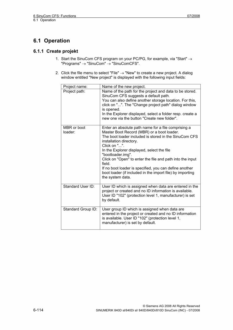
6 SinuCom CFS: Functions 07/2008 6.1 Operation
© Siemens AG 2008 All Rights Reserved 6-114 SINUMERIK 840D sl/840Di sl/ 840D/840Di/810D SinuCom (INC) - 07/2008
6.1 Operation
6.1.1 Create projekt 1. Start the SinuCom CFS program on your PC/PG, for example, via "Start" →
"Programs" → "SinuCom" → "SinuComCFS".
2. Click the file menu to select "File" → "New" to create a new project. A dialog window entitled "New project" is displayed with the following input fields:
Project name: Name of the new project. Project path: Name of the path for the project and data to be stored.
SinuCom CFS suggests a default path. You can also define another storage location. For this, click on "...". The "Change project path" dialog window is opened. In the Explorer displayed, select a folder resp. create a new one via the button "Create new folder".
MBR or boot loader:
Enter an absolute path name for a file comprising a Master Boot Record (MBR) or a boot loader. The boot loader included is stored in the SinuCom CFS installation directory. Click on "...". In the Explorer displayed, select the file "bootloader.img". Click on "Open" to enter the file and path into the input field. If no boot loader is specified, you can define another boot loader (if included in the import file) by importing the system data.
Standard User ID: User ID which is assigned when data are entered in the project or created and no ID information is available. User ID "102" (protection level 1, manufacturer) is set by default.
Standard Group ID: User group ID which is assigned when data are entered in the project or created and no ID information is available. User ID "102" (protection level 1, manufacturer) is set by default.
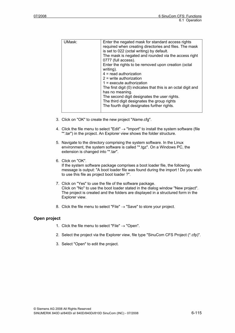
07/2008 6 SinuCom CFS: Functions 6.1 Operation
© Siemens AG 2008 All Rights Reserved SINUMERIK 840D sl/840Di sl/ 840D/840Di/810D SinuCom (INC) - 07/2008 6-115
UMask: Enter the negated mask for standard access rights
required when creating directories and files. The mask is set to 022 (octal writing) by default. The mask is negated and rounded via the access right 0777 (full access). Enter the rights to be removed upon creation (octal writing). 4 = read authorization 2 = write authorization 1 = execute authorization The first digit (0) indicates that this is an octal digit and has no meaning. The second digit designates the user rights. The third digit designates the group rights The fourth digit designates further rights.
3. Click on "OK" to create the new project "Name.cfg". 4. Click the file menu to select "Edit" → "Import" to install the system software (file
"*.tar") in the project. An Explorer view shows the folder structure.
5. Navigate to the directory comprising the system software. In the Linux environment, the system software is called "*.tgz". On a Windows PC, the extension is changed into "*.tar".
6. Click on "OK". If the system software package comprises a boot loader file, the following message is output: "A boot loader file was found during the import ! Do you wish to use this file as project boot loader ?".
7. Click on "Yes" to use the file of the software package. Click on "No" to use the boot loader stated in the dialog window "New project". The project is created and the folders are displayed in a structured form in the Explorer view.
8. Click the file menu to select "File" → "Save" to store your project.
Open project 1. Click the file menu to select "File" → "Open".
2. Select the project via the Explorer view, file type "SinuCom CFS Project (*.cfp)".
3. Select "Open" to edit the project.
6 SinuCom CFS: Functions 07/2008 6.1 Operation
© Siemens AG 2008 All Rights Reserved 6-116 SINUMERIK 840D sl/840Di sl/ 840D/840Di/810D SinuCom (INC) - 07/2008
Edit project The menu "Edit" offers the following commands for project processing:
• Select "Cut" to delete marked data from the project and transfer them to the clipboard.
• Select "Copy" to copy marked data from the project to the clipboard.
• Select "Paste" to insert marked data from the clipboard into the project.
• Select "Delete" to delete marked data from the project.
• Select "Rename" to rename marked data in the project.
• Select "Properties" to display the name, type, location and current access rights of marked data.
• Select "Import" to import data from “*.tar.gz“ archives into the project.
6.1.2 Set up project views The menu "Window" allows to display several views of one or several projects. The following options are available:
• Select "New window" to open another window showing the same contents as the active window. This allows to display different views of the same project. If you change the contents in an open window, these modifications are also made in all windows comprising the same project. When you open a new window, this becomes the active window and is displayed on top.
• Select "Cascade" to display all open windows one upon the other.
• Select "Tile" to display all open windows adjacently.
• Select "Arrange icons" to arrange the icons of the minimized windows in the lower area of the main window. If an open window is located in the lower area, some or all icons may be hidden since they are located underneath the project window.
• Following the commands, SinuCom CFS displays a list of currently open project windows. The active window is marked with a checkmark. To activate a window, select a project from the list.
07/2008 6 SinuCom CFS: Functions 6.1 Operation
© Siemens AG 2008 All Rights Reserved SINUMERIK 840D sl/840Di sl/ 840D/840Di/810D SinuCom (INC) - 07/2008 6-117
6.1.3 Generate image To create an image of your Linux Ext3 project, proceed as follows: 1. Click the file menu to select "File" → "Generate image...". The dialog window
"Save as..." opens.
2. Enter a file name for the image.
3. Press "Save". If there is already a file *.img", the system issues a safety prompt asking you whether you wish to replace the existing file. Select "Yes", to overwrite the existing file. Or press “Abort” and assign a new file name. Press "Save" again to start image generation.
4. You can monitor the generation process in the dialog window "Generate image ...". As soon as the generation process has been completed, the result is displayed as follows: Directory creation, file creation, user ID, group ID and access right settings ! At the end, you will be informed whether the process has been terminated correctly. While the generation process is running, you cannot select this field (read authorization only). You can mark and save information via Copy/Paste.
5. Press "OK" to terminate this process.
6.1.4 Read in / out image on the CompactFlash Card
Specify additional programs Additional programs have to be specified to write image files from SinuCom CFS onto a CompactFlash Card resp. read out CompactFlash Card image files from SinuCom CFS. 1. Click the file menu to select "View" → "Option". The dialog window "Options"
"General" tab is opened.
2. Place the cursor in the input field "write program:", enter a program (together with the relevant parameters) to be called when writing an image file from SinuCom CFS onto a CompactFlash Card. If you click on "..." next to the input field, you can select the program via the Explorer. Complete the parameters. As a wildcard for the object from SinuCom CFS, enter "%1" where applicable, followed by the CompactFlash Card target drive, e.g. "G:". Example: C:\Siemens\Sinumerik\SinuComCFS\installdisk.exe --verbose --blocksize 512k "%1" G
6 SinuCom CFS: Functions 07/2008 6.1 Operation
© Siemens AG 2008 All Rights Reserved 6-118 SINUMERIK 840D sl/840Di sl/ 840D/840Di/810D SinuCom (INC) - 07/2008
3. Place the cursor in the input field "read program:" enter a program (together with the relevant parameters) to be called when reading a SinuCom CFS image file from the CompactFlash Card. If you click on "..." next to the input field, you can select the program via the Explorer. Complete the parameters. As a wildcard for the object from SinuCom CFS, enter "%1" where applicable, followed by the CompactFlash Card source drive, e.g. "G:". Example: C:\Siemens\Sinumerik\SinuComCFS\installdisk.exe --verbose --blocksize 512k --extract "%1" G:
Read in / out image on the CompactFlash Card
After setting the write program, select the icon in the toolbar to write the specified file from SinuCom CFS onto the CompactFlash Card. After setting the read program, select the icon in the toolbar to read the specified file from the CompactFlash Card into the SinuCom CFS.
6.1.5 Select language 1. Click the file menu to select "View" → "Options". The dialog window "Options" is
opened.
2. Select the "Languages" tab.
3. Select the language in which you wish to display the SinuCom CFS. Select German or English.
4. Click on "OK".
Note
Restart the program to activate the language setting.
07/2008 7 SinuCom ARC: Functions 7.1 Operation
© Siemens AG 2008 All Rights Reserved SINUMERIK 840D sl/840Di sl/ 840D/840Di/810D SinuCom (INC) - 07/2008 7-119
7 SinuCom ARC: Functions
7.1 Operation ...................................................................................... 7-120
7.2 Displaying the contents of the archive.......................................... 7-120
7.3 Editing the archive contents.......................................................... 7-120
7.4 Creating an archive....................................................................... 7-122
7
7 SinuCom ARC: Functions 07/2008 7.1 Operation
© Siemens AG 2008 All Rights Reserved 7-120 SINUMERIK 840D sl/840Di sl/ 840D/840Di/810D SinuCom (INC) - 07/2008
7.1 Operation Start the SinuCom FFS program on your PC/PG, for example, via "Start" → "Programs" → "SinuCom" → "SinuComFFS". You can call up the various functions of the program from the menu bar or directly from the user interface using the buttons. Help is available for all actions that can be called up via the "Help" menu.
7.2 Displaying the contents of the archive As soon as an archive has been loaded, the files contained in the archive appear in the basic display together with the • name • size
7.3 Editing the archive contents
Processing the ARC With SinuCom ARC you can • create new directories and files • change directories and files • copy and insert files/directories into the directories and subdirectories (via the
clipboard), and • delete files/directories You can call up the various functions of the program from the menu bar or directly from the user interface using the buttons.
Saving the ARC When the files of the archive file are complete, the archive file must be saved.
Exporting the ARC
You can export (transfer) an archive file by selecting menu items "File” → "Export” The dialog box "Export to" shows the target directory to which the archive file is exported. The same hierarchy is reproduced and the data are placed in the same hierarchy structure. At the same time the system automatically generates a standard import "description file" (see below).
Importing the ARC The ARC file is imported by selecting it in the window and then starting the function "File" → "Import": The target and "description file" containing the import instruction is displayed in the dialog box "Import from".
07/2008 7 SinuCom ARC: Functions 7.3 Editing the archive contents
© Siemens AG 2008 All Rights Reserved SINUMERIK 840D sl/840Di sl/ 840D/840Di/810D SinuCom (INC) - 07/2008 7-121
Description file For all ARC import actions, whether to an empty or existing archive, a description file containing the individual instructions for the import action must be specified. Each line of the file is read in and interpreted. Comments are either separated from the instruction itself by a ";" or stand alone in a line preceded by a ";" at the beginning of the line. The following commands are possible: "$$ROOT$$ = path name": Path name: Absolute path within the file system of the operating system. Specifies the path from which all relative paths in the following instructions are located. This instruction can occur several times within a single file. "Path_nameOS = Path_nameArchive": This instruction ensures that the content of Path_nameOS becomes the content of Path_nameArchive. Path_nameArchive is always an absolute path within the archive hierarchy in every instruction. Path_nameOS can be either a relative or absolute path. If Path_nameOS is a directory, Path_nameArchive is always interpreted as such, and the files and subdirectories of Path_nameOS are added to Path_nameArchive. The system attempts to create Path_nameArchive if it does not exist. If Path_nameOS is a file, Path_nameArchive must also assume a file name. The content of file Path_nameOS becomes the content of the file Path_nameArchive. If Pathname_Archive already exists, you are asked whether you want to overwrite the content. If the file does not yet exist, the program tries to create the file. Path_nameOS > Path_nameArchive": With this instruction, Path_nameOS is placed in directory Path_nameArchive. Path_nameArchive is then always an absolute path to a directory in the archive. If it does not exist, the program tries to create it. Path_nameOS can be either a relative or absolute path. If Path_nameOS is a directory, the directory and all the data it contains (files and subdirectories) are placed in Pathname_Archive. If Pathname_OS is a file, it is entered in Pathname_Archive under the same name. If this file already exists, you are asked whether it should be overwritten.
7 SinuCom ARC: Functions 07/2008 7.4 Creating an archive
© Siemens AG 2008 All Rights Reserved 7-122 SINUMERIK 840D sl/840Di sl/ 840D/840Di/810D SinuCom (INC) - 07/2008
7.4 Creating an archive Select "File" → "New" to create a new empty archive into which you can put files/directories.
Saving the ARC Once the files of the archive file are complete the archive file must be stored in Advanced format.
07/2008 8 SinuCom PCIN: Functions 8.1 Operation
© Siemens AG 2008 All Rights Reserved SINUMERIK 840D sl/840Di sl/ 840D/840Di/810D SinuCom (INC) - 07/2008 8-123
8 SinuCom PCIN: Functions
8.1 Operation ...................................................................................... 8-124
8.2 Functions ...................................................................................... 8-124
8.3 File WINPCIN.ini ........................................................................... 8-125
8
8 SinuCom PCIN: Functions 07/2008 8.1 Operation
© Siemens AG 2008 All Rights Reserved 8-124 SINUMERIK 840D sl/840Di sl/ 840D/840Di/810D SinuCom (INC) - 07/2008
8.1 Operation Start the SinuCom PCIN program on your PC/PG, for example, via "Start" → "Programs" → "SinuCom" → "SinuComPCIN".
8.2 Functions
Configuring the RS-232 interface (softkey RS-232 Config) You can set the RS-232 interface according to your individual needs and the requirements of the connected device, softkey RS-232 Config (or F1) . When you press the softkey, the selection image showing the various parameters is displayed. You now select one of the four settings with one of the assigned keys. (softkeys shift F1 to shift F4). Flow control The flow control controls the serial communication (data transmission) between transmitter and receiver. Both a hardware and a software procedure exist: • XON and XOFF software procedure (handshaking) for flow control with serial
data transmission. The receiver signals to the transmitter whether the data can be received (XON) or not (XOFF).
• DTR / DSR and RTS / CTS: Hardware procedure (handshaking) for flow control with serial data transmission.
Note
Wherever possible, hardware handshaking should be used as this is much quicker.
Transmission with error detection and correction With SinuCom PCIN you can activate the protocol Transmission with error detection and correction (ZMODEM): • High degree of error detection • If transmission fails, it is resumed again precisely at the point at which it was
interrupted. • Adapts the size of the transmitted blocks to the transmission conditions. If an error occurs during transmission, transmission is not aborted. The protocol attempts to resume data transmission from the point of interruption. This happens automatically. After five failed attempts transmission is then aborted.
Note
You can only activate transmission with error detection and correction with hardware handshaking RTS/CTS.
07/2008 8 SinuCom PCIN: Functions 8.3 File WINPCIN.ini
© Siemens AG 2008 All Rights Reserved SINUMERIK 840D sl/840Di sl/ 840D/840Di/810D SinuCom (INC) - 07/2008 8-125
Sending/receiving data (SEND DATA/RECEIVE DATA) You send data with SEND DATA (or F3) and receive data with RECEIVE DATA (or F2). In both procedures, you enter the source and target file name after triggering the procedure from a menu. You can cancel transmission with ABORT Transfer (or F4).
Editing data (Edit single archive file) Select a SINUMERIK archive file. A list of the files in this archive file is displayed. Double-click the selected file to transfer it to the editor where you can continue to work on it. Only individual files can be returned to the control.
Saving individual files from directories (Split archive) All the files of the selected archive are stored as individual files as of this directory.
Querying the RS-232 status window (Show RS-232 status) A status line with the status signals of the RS-232 interface is displayed here. (Red → no transmission possible // Green → transmission possible) For an explanation of the signals see PIN functions under Interconnection diagrams.
8.3 File WINPCIN.ini The tool SinuCom PCIN can also be parameterized by experts in the WINPCIN.ini file: The four possible settings enabled by pressing a key can be found in file WINPCIN.INI under User to USER3 or RS232_INI to RS232_INI3. [User] ; or [User1];[User2];[User3] Both paths for upload and download can be preset. Upload path=c:\winpcin\updata Download path=c:\winpcin\downdata If a different path is selected for uploading or downloading during a SinuCom PCIN "session", it remains valid for the duration of the program. Background=c:\v24\winpcin\myBild.jpg Here you can load your own logo image as a background. [RS232_INI] or [RS232_INI1] [RS232_INI2] [RS232_INI3] Softkey=USER Here you will find the softkey text. Bildschirm_aktiv=1 (Screen active) displays the file content in a window, only for transmitting data EOF=0 ; 0 = deactivated 1=activated Data transfer is stopped as soon as the EOF character is received, or during transmission the EOF character (03h) is additionally sent.
8 SinuCom PCIN: Functions 07/2008 8.3 File WINPCIN.ini
© Siemens AG 2008 All Rights Reserved 8-126 SINUMERIK 840D sl/840Di sl/ 840D/840Di/810D SinuCom (INC) - 07/2008
PortNumber=1 Settings=19200,N,8,1 This is where the serial interface is parameterized. The sequence is baudrate, parity , databit , stopbit Possible settings for baudrate : 300, 1200, 2400, 4800, 9600, 19200, 38400, 57600, 115200 Possible settings for parity : n=None;e=Even;o=Odd;m=Mark;s=Space Possible settings for number of data bits : 5 to 8 Possible settings for number of stop bits : 1, 1.5, 2 Handshaking=2 This is where the transmission control is set. 0=none No control -> in certain circumstances characters might be lost 1=rtscts Control through two hardware lines 2=xon/xoff Control through software together with two characters which can be transmitted to stop and continue transmission. Timeout=5 Transmission is aborted after the set time. Protocol=5 The data transmission protocol is set here Possible settings are PROTOCOL_ASCII = 0 or transmission with error detection and correction = 5 The internal sizes of the input buffer or output buffer are set with the two variables InBufferSize= 1536‚ default value OutBufferSize= 2048‚ default value Under the heading [COMMON] you will find the interface parameterization to be activated directly after power up DEFAULT=0 ; corresponds to USER or RS232_INI
07/2008 A Appendix
© Siemens AG 2008 All Rights Reserved SINUMERIK 840D sl/840Di sl/ 840D/840Di/810D SinuCom (INC) - 07/2008 A-127
A Appendix
A.1 Abbreviations ASCII American Standard Code for Information Interchange: Amerikanische Code-
Norm für den Informationsaustausch
ATW SinuCom NC SI Acceptance Test Wizard (a.k.a. "SI Wizard")
BTSS Operator panel interface ("BedienTafelSchnittStelle")
DB Data Block
GUD Global User Data
HMI Human Machine Interface
IPO Interpolation Task
LUD Local User Data
MD, or MaDa Machine Data
MDI Manual Data Interface
NC Numerical Control
NCDDE SINUMERIK HMI Base's MPI Communications Server (Numerical Control Dynamic Data Exchange)
NCK Numerical Control Kernel
NCU Numerical Control Unit (i.e., the real-time hardware)
NCW NC Connect Wizard, tool for connecting the NCK, PLC, and drives
OEM Original Equipment Manufacturer
PLC Programmable Logic Controller
PUD Program User Data (a.k.a. Program Global Variables)
SBH Test of Safe Operating Stop (SI)
A
A Appendix 07/2008
© Siemens AG 2008 All Rights Reserved A-128 SINUMERIK 840D sl/840Di sl/ 840D/840Di/810D SinuCom (INC) - 07/2008
SE Test of Safe Software Limit Switch (SI)
SG Test of Safely Reduced Speed (SI)
SI Safety Integrated
SPL Safe Programmable Logic (SI)
SRAM Static Random Access Memory
SYNACT Motion Synchronous Action
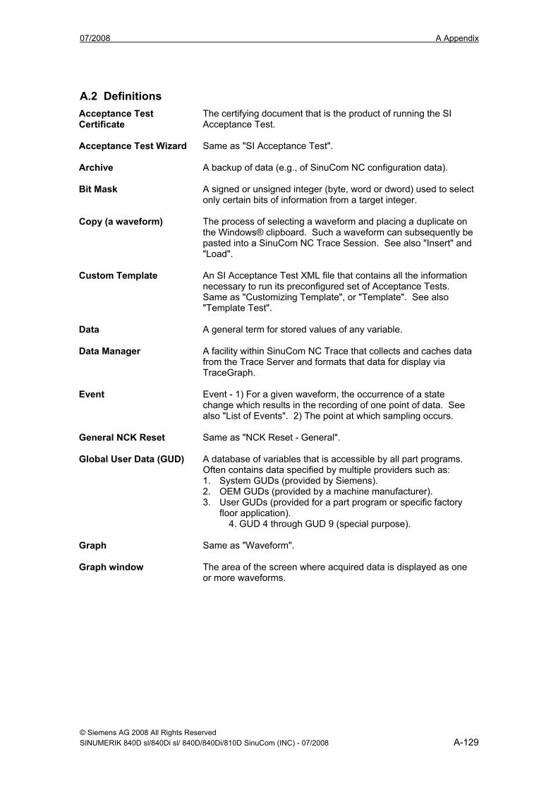
07/2008 A Appendix
© Siemens AG 2008 All Rights Reserved SINUMERIK 840D sl/840Di sl/ 840D/840Di/810D SinuCom (INC) - 07/2008 A-129
A.2 Definitions Acceptance Test Certificate
The certifying document that is the product of running the SI Acceptance Test.
Acceptance Test Wizard
Same as "SI Acceptance Test".
Archive A backup of data (e.g., of SinuCom NC configuration data).
Bit Mask A signed or unsigned integer (byte, word or dword) used to select only certain bits of information from a target integer.
Copy (a waveform) The process of selecting a waveform and placing a duplicate on the Windows® clipboard. Such a waveform can subsequently be pasted into a SinuCom NC Trace Session. See also "Insert" and "Load".
Custom Template An SI Acceptance Test XML file that contains all the information necessary to run its preconfigured set of Acceptance Tests. Same as "Customizing Template", or "Template". See also "Template Test".
Data A general term for stored values of any variable.
Data Manager A facility within SinuCom NC Trace that collects and caches data from the Trace Server and formats that data for display via TraceGraph.
Event Event - 1) For a given waveform, the occurrence of a state change which results in the recording of one point of data. See also "List of Events". 2) The point at which sampling occurs.
General NCK Reset Same as "NCK Reset - General".
Global User Data (GUD) A database of variables that is accessible by all part programs. Often contains data specified by multiple providers such as: 1. System GUDs (provided by Siemens). 2. OEM GUDs (provided by a machine manufacturer). 3. User GUDs (provided for a part program or specific factory
floor application). 4. GUD 4 through GUD 9 (special purpose).
Graph Same as "Waveform".
Graph window The area of the screen where acquired data is displayed as one or more waveforms.
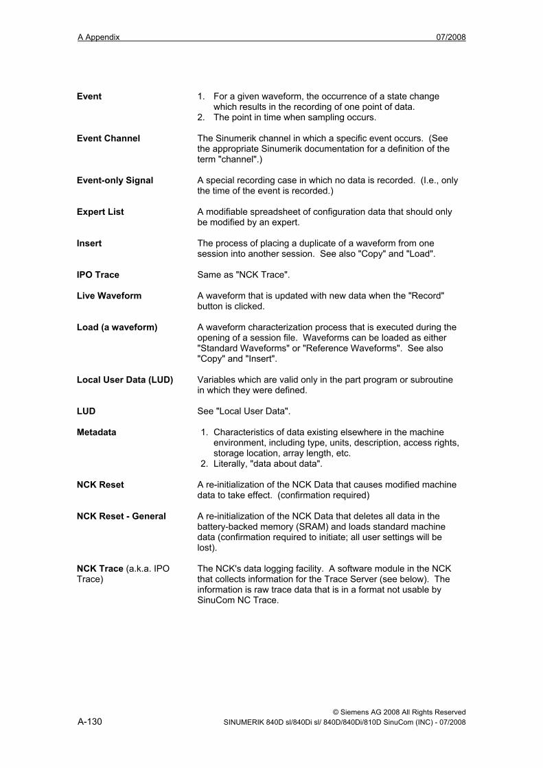
A Appendix 07/2008
© Siemens AG 2008 All Rights Reserved A-130 SINUMERIK 840D sl/840Di sl/ 840D/840Di/810D SinuCom (INC) - 07/2008
Event 1. For a given waveform, the occurrence of a state change
which results in the recording of one point of data. 2. The point in time when sampling occurs.
Event Channel The Sinumerik channel in which a specific event occurs. (See the appropriate Sinumerik documentation for a definition of the term "channel".)
Event-only Signal A special recording case in which no data is recorded. (I.e., only the time of the event is recorded.)
Expert List A modifiable spreadsheet of configuration data that should only be modified by an expert.
Insert The process of placing a duplicate of a waveform from one session into another session. See also "Copy" and "Load".
IPO Trace Same as "NCK Trace".
Live Waveform A waveform that is updated with new data when the "Record" button is clicked.
Load (a waveform) A waveform characterization process that is executed during the opening of a session file. Waveforms can be loaded as either "Standard Waveforms" or "Reference Waveforms". See also "Copy" and "Insert".
Local User Data (LUD) Variables which are valid only in the part program or subroutine in which they were defined.
LUD See "Local User Data".
Metadata 1. Characteristics of data existing elsewhere in the machine environment, including type, units, description, access rights, storage location, array length, etc.
2. Literally, "data about data".
NCK Reset A re-initialization of the NCK Data that causes modified machine data to take effect. (confirmation required)
NCK Reset - General A re-initialization of the NCK Data that deletes all data in the battery-backed memory (SRAM) and loads standard machine data (confirmation required to initiate; all user settings will be lost).
NCK Trace (a.k.a. IPO Trace)
The NCK's data logging facility. A software module in the NCK that collects information for the Trace Server (see below). The information is raw trace data that is in a format not usable by SinuCom NC Trace.
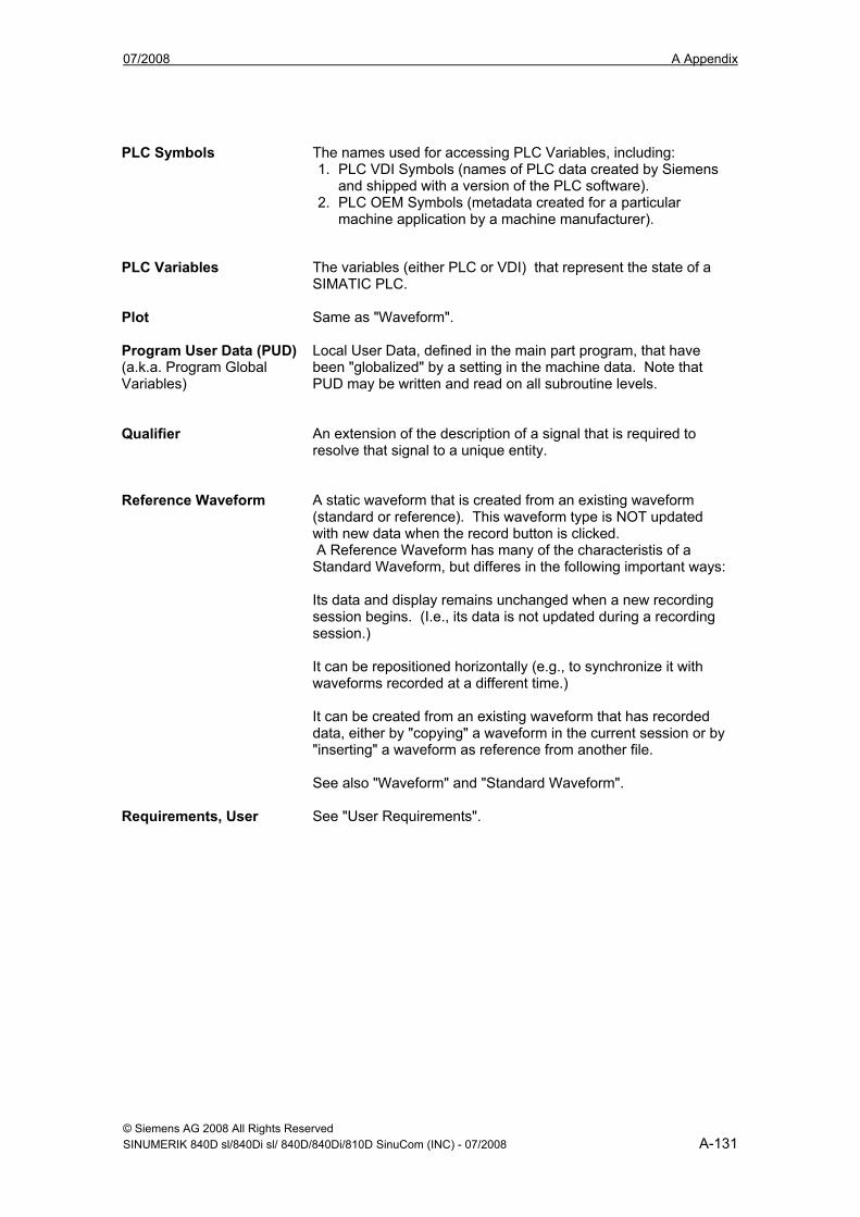
07/2008 A Appendix
© Siemens AG 2008 All Rights Reserved SINUMERIK 840D sl/840Di sl/ 840D/840Di/810D SinuCom (INC) - 07/2008 A-131
PLC Symbols The names used for accessing PLC Variables, including:
1. PLC VDI Symbols (names of PLC data created by Siemens and shipped with a version of the PLC software).
2. PLC OEM Symbols (metadata created for a particular machine application by a machine manufacturer).
PLC Variables The variables (either PLC or VDI) that represent the state of a
SIMATIC PLC.
Plot Same as "Waveform".
Program User Data (PUD) (a.k.a. Program Global Variables)
Local User Data, defined in the main part program, that have been "globalized" by a setting in the machine data. Note that PUD may be written and read on all subroutine levels.
Qualifier An extension of the description of a signal that is required to
resolve that signal to a unique entity.
Reference Waveform A static waveform that is created from an existing waveform
(standard or reference). This waveform type is NOT updated with new data when the record button is clicked. A Reference Waveform has many of the characteristis of a Standard Waveform, but differes in the following important ways: Its data and display remains unchanged when a new recording session begins. (I.e., its data is not updated during a recording session.) It can be repositioned horizontally (e.g., to synchronize it with waveforms recorded at a different time.) It can be created from an existing waveform that has recorded data, either by "copying" a waveform in the current session or by "inserting" a waveform as reference from another file. See also "Waveform" and "Standard Waveform".
Requirements, User See "User Requirements".
A Appendix 07/2008
© Siemens AG 2008 All Rights Reserved A-132 SINUMERIK 840D sl/840Di sl/ 840D/840Di/810D SinuCom (INC) - 07/2008
Safe Operating Stop A SinuCom NC SI Acceptance Test type which tests the ability of
a machine axis to stop safely.
Safe Software Limit Switch
A SinuCom NC SI Acceptance Test type which tests the software travel limits of a machine axis.
Safely Reduced Speed A SinuCom NC SI Acceptance Test type which tests the ability of a machine axis to safely reduce speed.
Session An environment constructed for the purpose of collecting data. This DATA can be used to display one or more waveforms in a configurable manner.
SI Acceptance Test A function in SinuCom NC which facilitates testing of safety-relevant machine functions and documentation of same, as required by EC Machine Directive EN954-1 (Control Category 3).
SI Wizard Same as "SI Acceptance Test".
Signal A variable that can be recorded by Trace, or can be used as one of the elements of a trigger.
Signal Data Same as "Data".
Signal Description Text providing information about a signal (can be overridden by the user).
Signal ID The unique numeric identifier (MD number) of a waveform (in the context of the SinuCom NC Trace "Setup: Waveforms" dialog).
Signal Name The name of a waveform.
Signal Specification Technical description of the signal as it is understood by the Sinumerik NCK or PLC...may be an address, a BTSS link item, a variable name, a Sinumerik reference, or other syntax.
SinuCom NC The configuration tool for commissioning of the Siemens SINUMERIK line of controls.
SinuCom NC Trace
A facility that records and plots dynamic information from the NC, drives, PLC, and/or HMI. Also known as “Trace HMI” and “Trace UI”. The SinuCom NC Trace application that runs when the user selects "Diagnostics-->Trace" from SinuCom NC. See also "trace" (lower case "t"). .
Standard Waveform A waveform that is updated with new data when the record button is clicked. See also "Waveform" and "Reference Waveform".
07/2008 A Appendix
© Siemens AG 2008 All Rights Reserved SINUMERIK 840D sl/840Di sl/ 840D/840Di/810D SinuCom (INC) - 07/2008 A-133
Start Trigger A trigger that initiates the recording of a waveform.
Stop Trigger A trigger that terminates the recording of a waveform.
Symbol A name for a piece of data in memory. With respect to Trace,
these can be GUDs or or PLC variables, and have the following common characteristics: 1. PLC VDI and NCK BTSS symbols are synchronous with a
release. 2. New symbols are added asynchronously to an NCK release. 3. New symbols are added asynchronously to a PLC release. 4. Users of Trace may be called upon to import these symbols.
Symbol File A file containing information correlating names with memory addresses. (Other metadata may also be present, depending on the source of the file.)
System Resources The resources that the NCK can provide. (E.g., if the NCK allows only one slot, only one Trace Application can run at a time.) Note also that User Requirements can exceed System Resources. See also "User Requirements".
Template Same as "Custom Template".
Template Test An installed test that is the result of loading a "SinuCom NC SI
Acceptance Test" custom template. See also "Custom Template".
Trace (upper case "T")
Same as "SinuCom NC Trace".
trace (lower case "t")
A generic term that applies to a graphical presentation of data, whether it is on a SINUMERIK control or elsewhere.
Trace Checker A utility service used to verify that adequate resources exist and are properly configured when a user attempts to run a SinuCom NC Trace application.
Trace Graph The graphical presentation facility of SinuCom NC Trace.
Trace Server 1. A facility within SINUMERIK that collects and caches data from NCK Trace and formats that data for it clients (e.g., SinuCom NC Trace, and SI Acceptance Test [through Trace UI Core]). Note that the caching of data is done asynchronously to the running of Trace. Additionally, the Trace Server transforms the data from a Trace Session XML file into a setup for a Trace Session.
A Appendix 07/2008
© Siemens AG 2008 All Rights Reserved A-134 SINUMERIK 840D sl/840Di sl/ 840D/840Di/810D SinuCom (INC) - 07/2008
Trace Session Same as "Session".
Trace Setup Wizard A six-screen user interface that allows easier configuration of
Trace Server and NCK IPO Trace features.
Trace Data Any data that is gathered that describes a waveform.
Trace HMI Same as "SinuCom NCTrace".
Trace UI Same as "SinuCom NCTrace".
Trace UI Core The trace facility with the Trace front end (i.e., SinuCom NC Trace's UI) stripped off, which provides the services necessary to display plots. Additionally, Trace UI Core is the repository for the display data pipeline between the Data Manager and TraceGraph. Trace UI Core can operate in the SINUMERIK environment where a mouse or other pointing device is not available.
Trace XML The storage format for the data.
Trigger 1. The occurrence of a state change that initiates or terminates the recording of a series of data points.
2. The satisfaction of the trigger level, according to the trigger mode, by the trigger waveform.
Trigger Event A specific entry in the list of events entitled "Trigger Event".
Trigger Level The value a trigger must achieve for the trigger event to occur.
(NOTE: Units for the selected trigger level are pre-defined in the database.)
Trigger Mode Either an arithmetic operator (e.g., "equals“, "greater“) or a characteristic of the trigger (e.g., "rising edge“).
Waveform A single graphical plot of a series of recorded data points that is
associated with a signal at an event (synonymous with "Plot", "Graph" and "Trace").
Waveform Data The complete set of data points, collected at the occurrences of the event, required to describe a given waveform (data plus the event). Recorded data representing the behavior, and thus the waveform, of any variable.
07/2008 I Index
© Siemens AG 2008 All Rights Reserved SINUMERIK 840D sl/840Di sl/ 840D/840Di/810D SinuCom (INC) - 07/2008 I-135
I Index
A
Acceptance Test Wizard ...................... 4-99 Advanced Features .............................. 4-97 Alarm Help............................................ 3-31 Alarm Messages................................... 4-36 Archive
Creating............................................. 4-42 Reading............................................. 4-43
Archiving............................................... 4-42
C
Common Advanced Configuration Items..................................................... 4-96 Common General Configuration Items. 4-96 Common Screen Contents ................. 4-101 Compatibility
with Microsoft Windows..................... 4-44 with Siemens Software...................... 4-43
Configuring the RS-232 interface....... 8-124 Context-sensitive help dialog box......... 3-29 Context-sensitive Help SW functions ... 3-30 Creating a project ................................. 3-28 Creating an archive
SinuCOM ARC ................................ 7-122 Customized Test Prompts .................. 4-105
D
Data aspect .......................................... 4-47 Dialog
Add Waveform .................................. 4-77 Setup Collection ................................ 4-81 Setup Sample Rates ......................... 4-85 Setup Trigger .................................... 4-84 Setup Waveforms.............................. 4-73
Dialog Display....................................... 4-37 Display of the NC image..................... 5-110 Displaying
the FFS............................................ 5-110
Displaying the contents of the archive 7-120 Displaying/editing the FFS image.......5-110
E
Editing the archive contents................7-120 Establishing a connection to the NC control .............................................2-21 Event aspect .........................................4-47 Exporting
the ARC ...........................................7-120 the FFS............................................5-111
F
Foreign languages ................................1-16 Functions
SinuCom............................................1-14 SinuCOM PCIN................................8-124
G
Generic Trace Client .............................4-97 Graph Windows ....................................4-49
H
Help functions .......................................3-29
I
Importing the ARC ...........................................7-120 the FFS............................................5-111
Installation SinuCom ARC ...................................2-24 SinuCom CFS....................................2-23 SinuCom FFS ....................................2-22 SinuCom NC......................................2-20 SinuCom PCIN ..................................2-25 variants ..............................................2-20
I
I Index 07/2008
© Siemens AG 2008 All Rights Reserved I-136 SINUMERIK 840D sl/840Di sl/ 840D/840Di/810D SinuCom (INC) - 07/2008
Installation and start-up with SinuCom NC......................................... 3-28
K
Keyboard operation key combinations .............................. 3-32
L
Licenses ............................................... 1-16
M
Machine Data activating ........................................... 4-39 changing............................................ 4-39 configuring......................................... 4-37 viewing .............................................. 4-37
Machine data Help ............................... 3-31 Machine Data Project Tree................... 4-39 Main Menu............................................ 4-35 Menu
Control............................................... 4-67 Edit .................................................... 4-59 File..................................................... 4-55 Setup ................................................. 4-66 View................................................... 4-63 Window.............................................. 4-67
Menus Context Menus .................................. 4-68 Gragh Windows................................. 4-68
N
NCK Versions....................................... 4-34
O
Operation SinuCOM ARC ..................... 7-120, 8-124 SinuCOM FFS................................. 5-110 SinuCom NC ..................................... 4-34
Ordering data SinuCom NC ..................................... 1-17
Overview How Trace is Used............................ 4-44
Overview Dialog ................................... 4-94
P
Parameterization window......................3-29 Passwords ............................................4-47 Permissible PC platforms .....................1-17 Processing
the ARC ...........................................7-120 the FFS............................................5-111
Product components.............................1-14 Product features....................................1-14 Projec....................................................3-29 Project tree............................................3-29
R
Reading an NC image from NC card .............5-111
Recording Basics Data and Events ................................4-47
S
Saving the ARC ...........................................7-120
Scale and Scroll Icons ..........................4-46 Scope of supply ....................................1-16 Service Data .........................................4-41 Setup Method Dialog ............................4-95 SI Acceptance Test Wizard ..................4-99 SinuCim NC 07.03
News..................................................4-35 SinuCom ARC
Overview............................................1-16 starting ...............................................2-24
SinuCom CFS Abbild auf CF-Card spielen .............6-118 Abbild erzeugen...............................6-117 Abbild von CF-Card lesen ...............6-118 Overview............................................1-16 Projekt bearbeiten ...........................6-116 Projekt öffnen...................................6-115 Projektansicht einrichten .................6-116 Sprache auswählen .........................6-118 starting ...............................................2-23 Zusatzprogramme angeben ............6-117
SinuCom FFS Overview............................................1-15 starting ...............................................2-22
SinuCom NC Available help ....................................3-29 Installation..........................................2-20 Permissible PC platforms ..................1-17 starting ...............................................2-20
07/2008 I Index
© Siemens AG 2008 All Rights Reserved SINUMERIK 840D sl/840Di sl/ 840D/840Di/810D SinuCom (INC) - 07/2008 I-137
SinuCom NC SI Overview ........................................... 1-15
SinuCom NC Trace ..................... 4-43, 4-97 Overview ........................................... 1-15
SinuCom PCIN Overview ........................................... 1-16
SINUMERIK SinuCom Product components ......................... 2-20
Starting SinuCom ARC................................... 2-24 SinuCom FFS.................................... 2-22 SinuCom NC ..................................... 2-20 SinuCom PCIN.................................. 2-25
Summary Screen.................................. 4-98 Supply medium..................................... 1-16 Supported Systems .............................. 4-34
T
Templates Creating Template........................... 4-106 Editor (CT)....................................... 4-107 Facts................................................ 4-105 Loading a Custom Template ........... 4-106 Modifyd Template............................ 4-106 Saving ............................................. 4-106 Unloading a Custom Template ....... 4-106 XML Structure ................................. 4-108
Toolbar Button Close Connection.............................. 4-36 Find in................................................ 4-36 Help (context sensitive)..................... 4-36 Info .................................................... 4-36 Online Project.................................... 4-36 Open Connection .............................. 4-36
Toolbar Buttons.....................................4-36 Toolbars ................................................4-54 Trace.....................................................4-43
Creating Reference Waveforms ........4-53 Definition............................................4-43 Dialogs...............................................4-73 Dragging ............................................4-53 Reference Waveforms.......................4-52 Sessions ............................................4-49 Toolbars and Menus..........................4-54 Use ....................................................4-43
Trace Setup Wizard (TSW)...................4-94 Trace Symbol Import Wizard (TSIW)....4-88 Transmission with error detection and correction
SinuCOM PCIN................................8-124
U
Uninstalling ...........................................2-26
W
WINPCIN.ini........................................8-125 Writing
an NC image to NC card .................5-111
X
XML Structure of the Custom Template .............................................4-108

I Index 07/2008
© Siemens AG 2008 All Rights Reserved I-138 SINUMERIK 840D sl/840Di sl/ 840D/840Di/810D SinuCom (INC) - 07/2008
To Siemens AG
Suggestions Corrections
I DT MC MS1 P.O. Box 3180
for documentation: SINUMERIK 840D sl/840Di sl/ 840D/840Di/810D
D-91050 Erlangen Fax +49 (0) 9131 / 98 – 2176 [Documentation]
mailto:[email protected]
SinuCom Installation/Service Tools Manufacturer/Service Documentation
From
Name:
Operating Manual Order No.: included in online help only
- 07/2008
Address of your company/department
Street:
Post code: ____________ Town:
Phone: __________ /
Fax: _______________ /
If you notice any printing errors when reading this documentation, please use the preprinted form to advise us of these. We would also be grateful for ideas and suggestions on how we can improve this documentation.
Suggestions and/or corrections