Embed Size (px)
Citation preview
Single-Sided AC Magnetic Fields For Induction Heating
Al-Thaddeus Avestruz, Arthur H. Chang, Shahriar Khushrushahi, Arijit Banerjee, Steven B. Leeb Laboratory for Electromagnetic and Electronic Systems
Massachusetts Institute of Technology Cambridge, MA USA
Abstract—We present simulations and demonstrate experimentally a new concept in winding a planar induction heater. The winding results in minimal ac magnetic field below the plane of the heater, while concentrating the flux above. Ferrites and other types of magnetic shielding are typically not required. The concept of a one-sided ac field can generalized to other geometries as well.
Keywords—induction heating; Halbach; one-sided flux; ac Halbach; single-sided field; induction cooker
I. INTRODUCTION
Induction heating is used in industrial [2], medical [3, 4], and home consumer [5, 6] applications. One of the key concerns in induction heating is containing the stray magnetic fields; solutions include both active and passive shielding, which are extrinsic to the induction coil design [7-12].
We demonstrate a new winding arrangement based on a Halbach array, which in an ideal form results in a field on only one side of a geometric surface [13, 14]. These surfaces can be general and along with planar designs, cylindrical and spherical surfaces, among others, are possible [15, 16]. Traditionally, these Halbach configurations have been used to generate dc magnetic fields, but we show that ac fields can also be generated with one-sided characteristics.
In this paper, we present both finite element simulation and experimental results for a prototype winding arrangement of a planar induction heater based on a two-dimensional Halbach configuration. By using a Halbach winding configuration, the flux cancelation is achieved implicitly without the use of passive shields such as ferrite plates, conductor plates, or active shielding. In doing so, cost, weight, and size are reduced, along with an improvement in mechanical robustness by not using ferrites.
II. HALBACH WINDING
Both Halbach [13] and Mallinson [14] independently posited magnetization configurations that elicit one-sided magnetic fluxes. Some of the theory for the ideal cases is derived in [15]; in the ideal case, the field has a sinusoidal variation on the plane of the array, falls off exponentially from the top surface, and is zero below. We can derive the magnetic flux density at a point z above and x along the Halbach surface with thickness d as
( )0 0 1 coskd kzB M e e kxμ − −= − . (1)
2 /k π λ= is the radian reciprocal of the array wavelength and for a wound Halbach array 0M kNIα= , where NI are the amp-turns andα is a geometric factor.
The faster fall-off in field resulting from a Halbach surface can be advantageous in induction cooking appliances, including wide area, flexible cooking zones [17] because the bottom of the pans are close to the surface so power transfer can be achieved while still minimizing stray fields.
Fig. 1 illustrates the construction of a one-sided dc field using magnetizations from block permanent magnets. It shows
(a)
(b)
(c)
Fig. 2. Compression of a Unit Cell for a Wound Halbach Array
Fig. 1. DC Halbach Array [1]
978-1-4799-0224-8/13/$31.00 ©2013 IEEE 5052
how the superposition of an alternating pattern of vertical and horizontal magnetizations combine to produce twice the field on top and none on the bottom. For this case of a non-sinusoidal magnetization, a spatial Fourier decomposition could be used for analysis similar to [18], with the fundamental component given by (1).
An example of a wound dc Halbach array can be found in [18]. In Fig. 2a, we approximate each magnetization with a three turn winding. If we compress the windings together as in
Fig. 2c, there is a doubling of amp-turns in some of the turns in the top layer, and cancelations on the bottom layer. This arrangement reduces the winding complexity with a decreasing
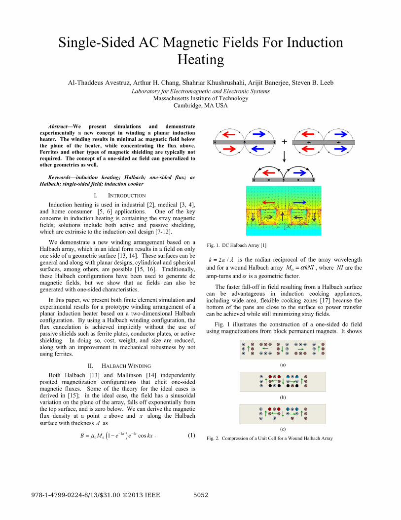
Fig. 3. Two-Dimensional Winding Halbach Approximation. Arrows indicate per unit ampere-turns for the top layer of the winding structure.
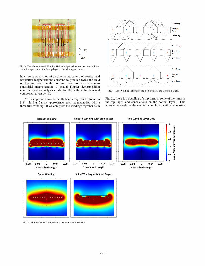
Fig. 5. Finite Element Simulations of Magnetic Flux Density
Fig. 4. Lap Winding Pattern for the Top, Middle, and Bottom Layers.
5053
winding density with each layer. Fig. 3 shows the top layer of a two-dimensional implementation of the array. A two-dimensional approach means that each layer can be wound independently, which results in a reduction in winding and hence manufacturing complexity. Fig. 4 illustrates the lap windings schematically for each layer.
III. FINITE ELEMENT SIMULATIONS
We performed finite element simulations in COMSOL for frequency-dependent magnetic induction. In addition, we performed a simulation using a multiphysics model that included heat conduction, convection, and radiation.
A. Magnetic Field Modeling
We performed simulations at the nominal operating frequency of 500 kHz. By using a thin-wire approximation, skin and proximity effects in the winding can be neglected; this is a valid model for an experiment if the appropriate Litz wire is used.
Figure 5 illustrates two-dimensional simulations of the magnetic flux density for several winding configurations. Our three-layer Halbach winding arrangement is shown. What is noticeable is that the additional field below from adding a steel target on top of a Halbach winding is negligible. In addition, one observes that in comparison to a winding where only the top winding layer is used, the complete three-layer Halbach winding has a significantly higher concentration of magnetic flux above and a field that does not extend as far below.
Spiral windings are commonly used in induction stove applications [6]; the configuration shown does not have the typically used ferrite substrate, and thus results in an extensive two-sided field. One observes that in placing a steel target, the flux at bottom increases and extends farther; this can imply that if a ferrite substrate were used on the bottom, the flux density it must carry is larger with a heating target, hence possibly resulting in higher overall loss.
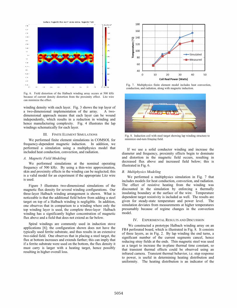
If we use a solid conductor winding and increase the diameter and frequency, proximity effects begin to dominate and distortion in the magnetic field occurs, resulting in decreased flux above and increased field below; this is illustrated in Fig. 6.
B. Multiphysics Modeling
We performed a multiphysics simulation in Fig. 7 that includes models for heat conduction, convection, and radiation. The effect of resistive heating from the winding was discounted in the simulation by enforcing a thermally insulating boundary at the surface of the wire. Temperature dependent target resistivity is included as well. The results are given for steady-state temperature and power level. The simulation deviates from measurements at higher temperatures presumably because of regime changes in the convection model.
IV. EXPERIMENTAL RESULTS AND DISCUSSION
We constructed a prototype Halbach winding array on an FR4 perforated board, which is illustrated in Fig. 8. It consists of three layers, as in Fig. 2. By lap winding the end turns, a significant number of the current segments cancel, hence reducing stray fields at the ends. Thin magnetic steel was used as a target to increase the in-plane thermal time constant, so that transient thermal effects could be observed using an infrared camera. Transient thermal behavior, i.e. step response to power, is useful in determining heating distribution and uniformity. The heating distribution is an indicator of the
Fig. 6. Field distortion of the Halbach winding array occurs at 500 kHz because of current density distortion from the proximity effect. Litz wire can minimize the effect.
Fig. 7. Multiphysics finite element model includes heat convection, conduction, and radiation, along with magnetic induction.
Fig. 8. Induction coil with steel target showing lap winding structure to minimize end-turn fringing field.
5054
induced currents and hence magnetic flux distribution at the target. The top surface of the target was coated with high temperature black paint and calibrated to a thermocouple to calculate an emissivity of 0.97, which is needed for infrared temperature measurements.
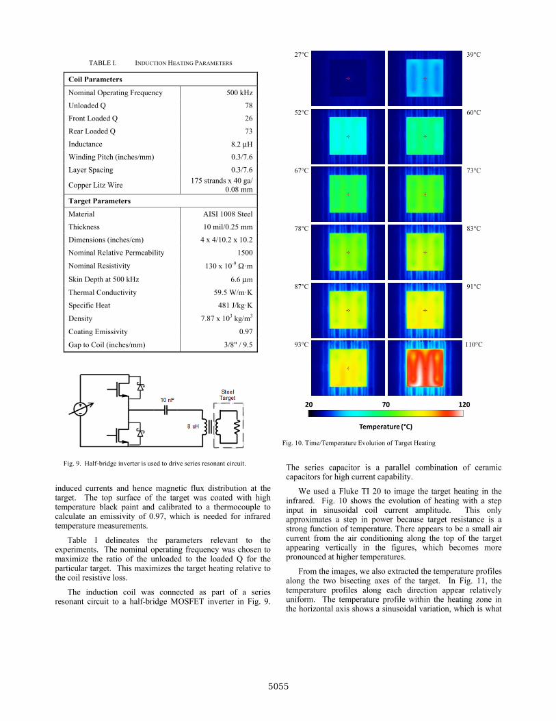
Table I delineates the parameters relevant to the experiments. The nominal operating frequency was chosen to maximize the ratio of the unloaded to the loaded Q for the particular target. This maximizes the target heating relative to the coil resistive loss.
The induction coil was connected as part of a series resonant circuit to a half-bridge MOSFET inverter in Fig. 9.
The series capacitor is a parallel combination of ceramic capacitors for high current capability.
We used a Fluke TI 20 to image the target heating in the infrared. Fig. 10 shows the evolution of heating with a step input in sinusoidal coil current amplitude. This only approximates a step in power because target resistance is a strong function of temperature. There appears to be a small air current from the air conditioning along the top of the target appearing vertically in the figures, which becomes more pronounced at higher temperatures.
From the images, we also extracted the temperature profiles along the two bisecting axes of the target. In Fig. 11, the temperature profiles along each direction appear relatively uniform. The temperature profile within the heating zone in the horizontal axis shows a sinusoidal variation, which is what
TABLE I. INDUCTION HEATING PARAMETERS
Coil Parameters
Nominal Operating Frequency 500 kHz
Unloaded Q 78
Front Loaded Q 26
Rear Loaded Q 73
Inductance 8.2 μH
Winding Pitch (inches/mm) 0.3/7.6
Layer Spacing 0.3/7.6
Copper Litz Wire 175 strands x 40 ga/
0.08 mm
Target Parameters
Material AISI 1008 Steel
Thickness 10 mil/0.25 mm
Dimensions (inches/cm) 4 x 4/10.2 x 10.2
Nominal Relative Permeability 1500
Nominal Resistivity 130 x 10-9 Ω·m
Skin Depth at 500 kHz 6.6 μm
Thermal Conductivity 59.5 W/m·K
Specific Heat 481 J/kg·K
Density 7.87 x 10³ kg/m3
Coating Emissivity 0.97
Gap to Coil (inches/mm) 3/8" / 9.5
Fig. 9. Half-bridge inverter is used to drive series resonant circuit.
27°C 39°C
52°C 60°C
67°C 73°C
78°C 83°C
87°C 91°C
93°C 110°C
Fig. 10. Time/Temperature Evolution of Target Heating
5055
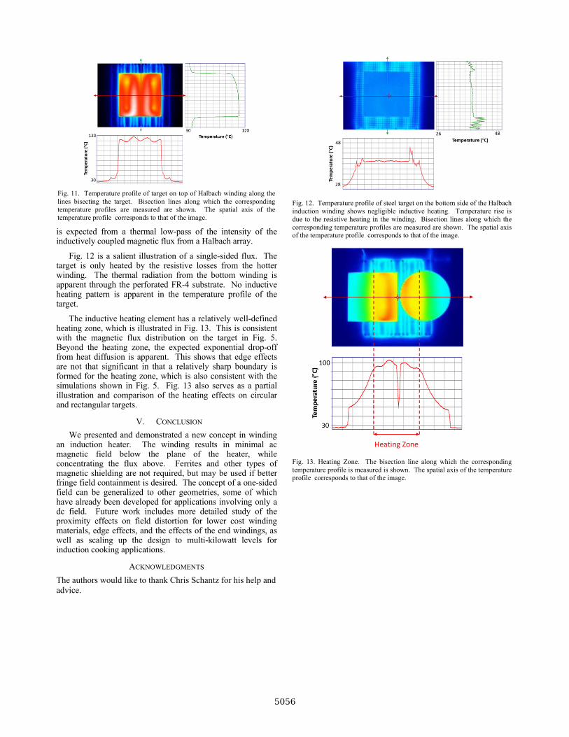
is expected from a thermal low-pass of the intensity of the inductively coupled magnetic flux from a Halbach array.
Fig. 12 is a salient illustration of a single-sided flux. The target is only heated by the resistive losses from the hotter winding. The thermal radiation from the bottom winding is apparent through the perforated FR-4 substrate. No inductive heating pattern is apparent in the temperature profile of the target.
The inductive heating element has a relatively well-defined heating zone, which is illustrated in Fig. 13. This is consistent with the magnetic flux distribution on the target in Fig. 5. Beyond the heating zone, the expected exponential drop-off from heat diffusion is apparent. This shows that edge effects are not that significant in that a relatively sharp boundary is formed for the heating zone, which is also consistent with the simulations shown in Fig. 5. Fig. 13 also serves as a partial illustration and comparison of the heating effects on circular and rectangular targets.
V. CONCLUSION
We presented and demonstrated a new concept in winding an induction heater. The winding results in minimal ac magnetic field below the plane of the heater, while concentrating the flux above. Ferrites and other types of magnetic shielding are not required, but may be used if better fringe field containment is desired. The concept of a one-sided field can be generalized to other geometries, some of which have already been developed for applications involving only a dc field. Future work includes more detailed study of the proximity effects on field distortion for lower cost winding materials, edge effects, and the effects of the end windings, as well as scaling up the design to multi-kilowatt levels for induction cooking applications.
ACKNOWLEDGMENTS
The authors would like to thank Chris Schantz for his help and advice.
Fig. 12. Temperature profile of steel target on the bottom side of the Halbach induction winding shows negligible inductive heating. Temperature rise is due to the resistive heating in the winding. Bisection lines along which the corresponding temperature profiles are measured are shown. The spatial axis of the temperature profile corresponds to that of the image.
Fig. 13. Heating Zone. The bisection line along which the corresponding temperature profile is measured is shown. The spatial axis of the temperature profile corresponds to that of the image.
Fig. 11. Temperature profile of target on top of Halbach winding along the lines bisecting the target. Bisection lines along which the corresponding temperature profiles are measured are shown. The spatial axis of the temperature profile corresponds to that of the image.
5056
REFERENCES
[1] Halbach Array. Available: http://en.wikipedia.org/wiki/Halbach_array
[2] V. Rudnev, Handbook of induction heating. New York: Marcel Dekker, 2003.
[3] J. R. Oleson, "A review of magnetic induction methods for hyperthermia treatment of cancer," IEEE Trans Biomed Eng, vol. 31, pp. 91-7, Jan 1984.
[4] P. R. Stauffer, P. K. Sneed, H. Hashemi, and T. L. Phillips, "Practical induction heating coil designs for clinical hyperthermia with ferromagnetic implants," IEEE Trans Biomed Eng, vol. 41, pp. 17-28, Jan 1994.
[5] W. C. Moreland, "The Induction Range: Its Performance and Its Development Problems," Industry Applications, IEEE Transactions on, vol. IA-9, pp. 81-85, 1973.
[6] J. Acero, J. Burdio, L. Barragan, D. Navarro, R. Alonso, J. Garcia, et al., "The domestic induction heating appliance: An overview of recent research," in Applied Power Electronics Conference and Exposition, 2008. APEC 2008. Twenty-Third Annual IEEE, 2008, pp. 651-657.
[7] P. Sergeant, U. Adriano, L. Dupre, O. Bottauscio, M. De Wulf, M. Zucca, et al., "Passive and active electromagnetic shielding of induction heaters," Magnetics, IEEE Transactions on, vol. 40, pp. 675-678, 2004.
[8] P. Sergeant, L. Dupre, and J. Melkebeek, "Optimizing a transformer driven active magnetic shield in induction heating," Compel-the International Journal for Computation and Mathematics in Electrical and Electronic Engineering, vol. 24, pp. 1241-1257, 2005.
[9] P. Sergeant, L. Dupre, and J. Melkebeek, "Active and passive magnetic shielding for stray field reduction of an induction heater with axial flux," Electric Power Applications, IEE Proceedings -, vol. 152, pp. 1359-1364, 2005.
[10] P. Sergeant, D. Hectors, L. Dupre, and K. Van Reusel, "Thermal analysis of magnetic shields for induction heating," Electric Power Applications, IET, vol. 3, pp. 543-550, 2009.
[11] P. Sergeant, D. Hectors, L. Dupre, and K. Van Reusel, "Magnetic Shielding of Levitation Melting Devices," Magnetics, IEEE Transactions on, vol. 46, pp. 686-689, 2010.
[12] P. Sergeant, R. V. Sabariego, G. Crevecoeur, L. Dupre, and C. Geuzaine, "Analysis of perforated magnetic shields for electric power applications," Electric Power Applications, IET, vol. 3, pp. 123-132, 2009.
[13] K. Halbach, "Design of Permanent Multipole Magnets with Oriented Rare-Earth Cobalt Material," Nuclear Instruments & Methods, vol. 169, pp. 1-10, 1980.
[14] J. C. Mallinson, "One-sided fluxes -- A magnetic curiosity?," Magnetics, IEEE Transactions on, vol. 9, pp. 678-682, 1973.
[15] H. A. Shute, J. C. Mallinson, D. T. Wilton, and D. J. Mapps, "One-sided fluxes in planar, cylindrical, and spherical magnetized structures," Magnetics, IEEE Transactions on, vol. 36, pp. 440-451, 2000.
[16] H. A. Shute, J. C. Mallinson, and D. T. Wilton, "One-sided fluxes in elliptical cylinders," Magnetics, IEEE Transactions on, vol. 37, pp. 2966-2969, 2001.
[17] F. Sanz, C. Franco, C. Sagues, D. Paesa, and S. Llorente, "Flexible cooking zone with 2D mobile inductors in induction hobs," in IECON 2012-38th Annual Conference on IEEE Industrial Electronics Society, 2012, pp. 3262-3267.
[18] G. Zhou, X. Huang, H. Jiang, and R. Bo, "Design and analysis of a novel ironless trapezoid winding array with single-sided and well sinusoidal magnetic field," in Electromagnetic Field Computation (CEFC), 2010 14th Biennial IEEE Conference on, 2010, pp. 1-1.
5057
Powered by TCPDF (www.tcpdf.org)