Embed Size (px)
Citation preview

http://support.automation.siemens.com/WW/view/en/82843076
2015.07.16
SINAMICS G: Control of a G120/G130/G150
with an Allen-Bradley controller (Compact/
ControlLogix with RSLogix 5000) via
EtherNet/IP

SINAMICS G: Control of a G120/130/150 with an Allen-Bradleycontroller (Compact/ ControlLogix with RSLogix 5000) via EtherNet/IPEntry-ID: 82843076, V3.0, 07/2015 2
ãS
iem
ens
AG
Cop
yrig
ht20
15A
llrig
hts
rese
rved
Warranty and LiabilityNote The Application Examples are not binding and do not claim to be complete
regarding the circuits shown, equipping and any eventuality. The ApplicationExamples do not represent customer-specific solutions. They are only intendedto provide support for typical applications. You are responsible for ensuring thatthe described products are used correctly. These application examples do notrelieve you of the responsibility to use sound practices in application, installation,operation and maintenance. When using these Application Examples, yourecognize that we cannot be made liable for any damage/claims beyond theliability clause described. We reserve the right to make changes to theseApplication Examples at any time without prior notice. If there are any deviationsbetween the recommendations provided in these application examples and otherSiemens publications – e.g. Catalogs – the contents of the other documentshave priority.
We do not accept any liability for the information contained in this document.
Any claims against us – based on whatever legal reason – resulting from the use ofthe examples, information, programs, engineering and performance data etc.,described in this Application Example shall be excluded. Such an exclusion shallnot apply in the case of mandatory liability, e.g. under the German Product LiabilityAct (“Produkthaftungsgesetz”), in case of intent, gross negligence, or injury of life,body or health, guarantee for the quality of a product, fraudulent concealment of adeficiency or breach of a condition which goes to the root of the contract(“wesentliche Vertragspflichten”). The damages for a breach of a substantialcontractual obligation are, however, limited to the foreseeable damage, typical forthe type of contract, except in the event of intent or gross negligence or injury tolife, body or health. The above provisions do not imply a change of the burden ofproof to your detriment.
Any form of duplication or distribution of these Application Examples or excerptshereof is prohibited without the expressed consent of Siemens Industry Sector.
If you have any questions concerning this document please e-mail us to thefollowing address:[email protected]
Securityinforma-tion
Siemens provides products and solutions with industrial security functions thatsupport the secure operation of plants, solutions, machines, equipment and/ornetworks. They are important components in a holistic industrial securityconcept. With this in mind, Siemens’ products and solutions undergo continuousdevelopment. Siemens recommends strongly that you regularly check forproduct updates.
For the secure operation of Siemens products and solutions, it is necessary totake suitable preventive action (e.g. cell protection concept) and integrate eachcomponent into a holistic, state-of-the-art industrial security concept. Third-partyproducts that may be in use should also be considered. For more informationabout industrial security, visit http://www.siemens.com/industrialsecurity.
To stay informed about product updates as they occur, sign up for a product-specific newsletter. For more information, visithttp://support.automation.siemens.com.
SINAMICS G: Control of a G120/130/150 with an Allen-Bradleycontroller (Compact/ ControlLogix with RSLogix 5000) via EtherNet/IPEntry-ID: 82843076, V3.0, 07/2015 3
ãS
iem
ens
AG
Cop
yrig
ht20
15A
llrig
hts
rese
rved
Table of contentsWarranty and Liability .............................................................................................. 2Table of contents...................................................................................................... 31 Task................................................................................................................. 5
1.1 EtherNet/IP Overview ........................................................................ 51.1.1 Industrial Ethernet ............................................................................. 51.1.2 Sinamics G series Connectivity to EtherNet/IP ................................... 5
2 Solution Overview .......................................................................................... 62.1 Solution Overview .............................................................................. 62.1.1 Hardware Structure............................................................................ 6
2.2 Used Components ............................................................................. 7
3 Programming Overview ................................................................................. 8
3.1 Configuration Methods ....................................................................... 8
3.3 AOI Types ....................................................................................... 10
4 Sinamics G Series Add-On Instructions ...................................................... 11
4.1 Function Description ........................................................................ 11
4.2 Telegram Descriptions ..................................................................... 114.2.1 Telegram Type 1 for Simple Speed .................................................. 114.2.2 Telegram Type 352 Speed Control .................................................. 114.2.3 Telegram Type 111 for EPOS mode ................................................ 12
4.3 Simple Speed Control –Telegram 1 ................................................. 134.3.1 Functionality .................................................................................... 134.3.2 Schematic Ladder Representation ................................................... 134.3.3 Input and Output Parameters ........................................................... 13
4.4 Speed Control –Telegram 352 ......................................................... 144.4.1 Functionality .................................................................................... 144.4.2 Schematic Ladder Representation ................................................... 154.4.3 Input and Output Parameters ........................................................... 15
4.5 EPOS Control .................................................................................. 174.5.1 Functionality .................................................................................... 174.5.2 Schematic Ladder Representation ................................................... 174.5.3 Input and Output Parameters ........................................................... 18
4.6 MDI Mode ........................................................................................ 204.6.1 Functionality .................................................................................... 204.6.2 Schematic Ladder representation .................................................... 214.6.3 Input and Output Parameters ........................................................... 22
4.7 UDTs ............................................................................................... 23
5 Drive Configuration ...................................................................................... 24
5.1 Configuration in STARTER .............................................................. 245.1.1 Setting the IP Address through Edit Ethernet Node .......................... 245.1.2 G120 Parameter Setting for EtherNet/IP Communication ................. 275.1.3 G130/150 Parameter Settings for EtherNet/IP Communication ......... 28
5.2 Using a Freely Configurable Telegram ............................................. 30
6 Configuring a Generic Ethernet Module ...................................................... 31
6.1 Adding a new module in RSLogix .................................................... 31

SINAMICS G: Control of a G120/130/150 with an Allen-Bradleycontroller (Compact/ ControlLogix with RSLogix 5000) via EtherNet/IPEntry-ID: 82843076, V3.0, 07/2015 4
ãS
iem
ens
AG
Cop
yrig
ht20
15A
llrig
hts
rese
rved
6.1.1 Inserting the module in an RSLogix project ...................................... 316.1.2 Configuring network parameters ...................................................... 326.1.3 Connection Parameters ................................................................... 326.1.4 Using the IO Data ............................................................................ 33
7 Using AOIs in a New Application ................................................................. 34
7.1 Importing AOIs ................................................................................ 347.1.1 Installing L5K Files in RSLogix ......................................................... 34
7.2 Using the AOI .................................................................................. 357.2.1 Adding AOI to an RSLogix Program ................................................. 357.2.2 I/O Interface..................................................................................... 36
8 Drive Parameter Access ............................................................................... 37
8.1 Explicit Messaging ........................................................................... 37
8.2 Using the MSG Instruction ............................................................... 38
9 Troubleshooting ........................................................................................... 4210 Glossary ........................................................................................................ 4511 History .......................................................................................................... 46

Task
SINAMICS G: Control of a G120/130/150 with an Allen-Bradleycontroller (Compact/ ControlLogix with RSLogix 5000) viaEtherNet/IP
SINAMICS G: Control of a G120/130/150 with an Allen-Bradleycontroller (Compact/ ControlLogix with RSLogix 5000) via EtherNet/IPEntry-ID: 82843076, V3.0, 07/2015 5
1 Task1.1 EtherNet/IP Overview
1.1.1 Industrial Ethernet
Industrial Ethernet communication networks continue to gain global importance inautomation solutions. Industrial Ethernet connectivity down to device levelcomponents (i.e. drives, I/O, etc.) is an end user requirement that demandsopenness and flexibility. To capitalize on the flexibility to connect to differentIndustrial Ethernet protocols the Sinamics G drives can seamlessly be applied inPROFINET and EtherNet/IP networks.
1.1.2 Sinamics G series Connectivity to EtherNet/IP
The Sinamics drive family offers both PROFINET and EtherNet/IP software stacksfor the Sinamics G series which is easily selected by a parameter setting in thestandard Sinamics firmware. The CBE20 communications option board for theCU320-2 control unit is required on the G130/G150 drives to communicate onEtherNet/IP.The network IP address of the Sinamics G drive can be set through the STARTERsoftware. With STARTER software installed on your computer you can connect tothe Sinamics drive through PROFINET or EtherNet/IP.The Sinamics drives operate on unicast telegrams which reduces network traffic.Sinamics G drives have been certified by ODVA for EtherNet/IP conformancetesting and participated in the EtherNet/IP PlugFest. Siemens is a member ofODVA with Vendor ID # 1251.

Solution Overview
SINAMICS G: Control of a G120/130/150 with an Allen-Bradleycontroller (Compact/ ControlLogix with RSLogix 5000) viaEtherNet/IP
SINAMICS G: Control of a G120/130/150 with an Allen-Bradleycontroller (Compact/ ControlLogix with RSLogix 5000) via EtherNet/IPEntry-ID: 82843076, V3.0, 07/2015 6
2 Solution Overview2.1 Solution Overview
2.1.1 Hardware Structure
Figure 2-1 Sample System Overview

Solution Overview
SINAMICS G: Control of a G120/130/150 with an Allen-Bradleycontroller (Compact/ ControlLogix with RSLogix 5000) viaEtherNet/IP
SINAMICS G: Control of a G120/130/150 with an Allen-Bradleycontroller (Compact/ ControlLogix with RSLogix 5000) via EtherNet/IPEntry-ID: 82843076, V3.0, 07/2015 7
2.2 Used Components
The application was generated with the following components:Hardware components
Table 1
Component No.
PROFINET versions of G120 with Firmware version 4.6 or later 1
CU320-2 PN/DP with CBE20 option board, and firmware version4.6 or later 1
Rockwell Automation Logix family controller Firmware version19 or later
1
Software componentsTable 2
Component No.
STARTER Version 4.3 SP2 or later 1RS Logix 5000 Version 20 or later 1
NOTE RSLogix 5000 Version 19 can be used when not using the EDS file

Programming Overview
SINAMICS G: Control of a G120/130/150 with an Allen-Bradleycontroller (Compact/ ControlLogix with RSLogix 5000) viaEtherNet/IP
SINAMICS G: Control of a G120/130/150 with an Allen-Bradleycontroller (Compact/ ControlLogix with RSLogix 5000) via EtherNet/IPEntry-ID: 82843076, V3.0, 07/2015 8
3 Programming Overview3.1 Configuration Methods
There are two methods to configure a Sinamics G series drive to communicateover EtherNet/IP. This manual will focus on the SINAMICS approach toconfiguration using Add On Instructions. This approach requires version 19 orhigher for RSLogix 5000. Alternatively, the drive can be set up for ODVA typeconfiguration. This allows the user to import a G120 EDS file and treat the drive asan ODVA AC drive object. This approach requires version 20 or higher for RSLogix5000. Refer to the diagram below for a general overview of the steps to configurewith either method.

Programming Overview
SINAMICS G: Control of a G120/130/150 with an Allen-Bradleycontroller (Compact/ ControlLogix with RSLogix 5000) viaEtherNet/IP
SINAMICS G: Control of a G120/130/150 with an Allen-Bradleycontroller (Compact/ ControlLogix with RSLogix 5000) via EtherNet/IPEntry-ID: 82843076, V3.0, 07/2015 9

3 Programming Overview
SINAMICS G: Control of a G120/130/150 with an Allen-Bradleycontroller (Compact/ ControlLogix with RSLogix 5000) via EtherNet/IPEntry-ID: 82843076, V3.0, 07/2015 10
ãS
iem
ens
AG
Cop
yrig
ht20
15A
llrig
hts
rese
rved
3.2 AOI’s for Sinamics G Series drives
The EtherNet/IP telegrams to the Sinamics G series drives can be freely configuredusing the free telegram structure for the message frame type. Alternatively in aneffort to seamlessly integrate the communication between a Sinamics G seriesdrive object and an AB Logix family controller Add On Instructions have beendesigned for the RSLogix programming that mimic standard telegrams used inSinamics G configurations. For most standard applications the use of the AOI’scan greatly reduce the Engineering time to configure a system. This manualdocuments the use of the AOI’s developed to simplify the integration of Sinamicsdrives connected to RSLogix automation systems over EtherNet/IP.
Figure 3-1 Example utilizing Simple Speed AOI and Standard Telegram 1
3.3 AOI Types
There are presently four Add On Instruction blocks that can be used for standardtelegrams T1, T352, and T111.
1. Simple Speed Standard Telegram 1 (2 words in / 2 words out)2. T352 Speed Control Standard Telegram 352 (6 words in / 6 words out)3. Easy Positioning Standard Telegram 111 (12 words in / 12 words out)4. Basic MDI Standard Telegram 111 (12 words in / 12 words out)

4 Sinamics G Series Add-On Instructions
SINAMICS G: Control of a G120/130/150 with an Allen-Bradleycontroller (Compact/ ControlLogix with RSLogix 5000) via EtherNet/IPEntry-ID: 82843076, V3.0, 07/2015 11
ãS
iem
ens
AG
Cop
yrig
ht20
15A
llrig
hts
rese
rved
4 Sinamics G Series Add-On Instructions4.1 Function Description
The Drive control function block (AOI) described in this section is intended toprovide Sinamics G series drive users with a quick and effective way to integratethe SINAMICS G drives into an automation system where a Logix family controlleris the primary control. The AOI can also be used as a starting point since the useris free to customize it to fit their specific application. The canned AOIs in thisapplication guide have been designed to seamlessly integrate with the PROFIdrivetelegrams T1, T352, and T111, commonly used for controlling Sinamics G drives.
4.2 Telegram Descriptions
4.2.1 Telegram Type 1 for Simple Speed
This telegram is a standard PROFIdrive telegram of 2 words in length. It will controlthe state of the drive by selecting the appropriate bits in the control word and setthe running speed in the speed setpoint word. For additional information on thistelegram and the details of its function, refer to the Sinamics G120/130/150Operating Instructions Manual and List manual.
Table 1 Telegram Type 1
WORD INPUT OUTPUT
1 Control Word 1 Status Word 12 Speed Setpoint Value Actual Speed Value
4.2.2 Telegram Type 352 Speed Control
This telegram is a standard PROFIdrive telegram of 6 words in length. It is similarto Telegram1 but with added functionality. There are 4 freely configurable wordsavailable for control of the drive. These could be a separate control word or analogvalues such torque limitation or additional speed setpoint. Status to the PLCcontains a standard Status word, Speed, Current, Torque, and present Faults orwarnings. For additional information on this telegram and the details of its function,refer to the Sinamics G120/130/150 Operating Instructions and List Manual.
Table 2 Telegram Type 352
WORD INPUT OUTPUT
1 Control Word 1 Status Word 12 Speed Setpoint Value Actual Speed Value3 User- Defined ABS_Current4 User- Defined Torque5 User- Defined Warn_Code6 User-Defined Fault_Code

4 Sinamics G Series Add-On Instructions
SINAMICS G: Control of a G120/130/150 with an Allen-Bradleycontroller (Compact/ ControlLogix with RSLogix 5000) via EtherNet/IPEntry-ID: 82843076, V3.0, 07/2015 12
ãS
iem
ens
AG
Cop
yrig
ht20
15A
llrig
hts
rese
rved
4.2.3 Telegram Type 111 for EPOS mode
Telegram 111 is a standard Siemens Telegram for a positioning drive. It allowssequence and control of the drive functions in addition to control of the positioningfunction EPOS. This interface is used for both the “MDI” control AOI and “EPOS”AOI. 12 Words of data are exchanged with the drive where the 12th word isreserved as a user selectable value. For detailed information on this telegram referto the Sinamics S120 List Manual Section 2.8 and Function Manual Section 10.1.
NOTE Telegram Type 1, 352, and 111 can also be applied to Sinamics G130 and G150drives utilizing the EtherNet/IP connectivity.
Table 2 Telegram Type 111
WORD Input Output
1 Control Word 1 Status Word 12 Pos Control Word 1 Pos Status Word 13 Pos Control Word 2 Pos Status Word 24 Control Word 2 Status Word 25 Velocity Override MELDW (Extended) Control Word
6-7 MDI Position Setpoint Position Actual Value8-9 MDI Velocity Setpoint Velocity Actual Value10 MDI Percent Acceleration Active Fault Number11 MDI Percent Deceleration Active Warning Number12 User Selectable User Selectable
4 Sinamics G Series Add-On Instructions
SINAMICS G: Control of a G120/130/150 with an Allen-Bradleycontroller (Compact/ ControlLogix with RSLogix 5000) via EtherNet/IPEntry-ID: 82843076, V3.0, 07/2015 13
ãS
iem
ens
AG
Cop
yrig
ht20
15A
llrig
hts
rese
rved
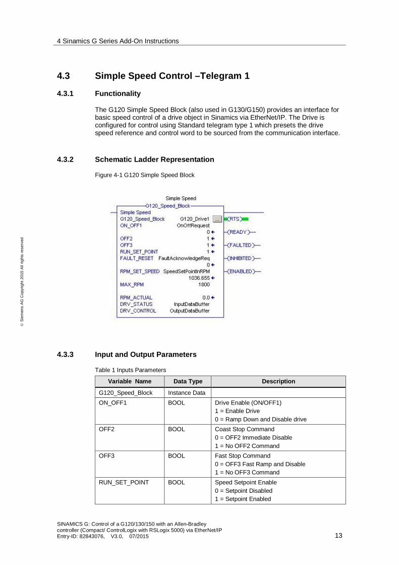
4.3 Simple Speed Control –Telegram 1
4.3.1 Functionality
The G120 Simple Speed Block (also used in G130/G150) provides an interface forbasic speed control of a drive object in Sinamics via EtherNet/IP. The Drive isconfigured for control using Standard telegram type 1 which presets the drivespeed reference and control word to be sourced from the communication interface.
4.3.2 Schematic Ladder Representation
Figure 4-1 G120 Simple Speed Block
4.3.3 Input and Output Parameters
Table 1 Inputs Parameters
Variable Name Data Type Description
G120_Speed_Block Instance DataON_OFF1 BOOL Drive Enable (ON/OFF1)
1 = Enable Drive0 = Ramp Down and Disable drive
OFF2 BOOL Coast Stop Command0 = OFF2 Immediate Disable1 = No OFF2 Command
OFF3 BOOL Fast Stop Command0 = OFF3 Fast Ramp and Disable1 = No OFF3 Command
RUN_SET_POINT BOOL Speed Setpoint Enable0 = Setpoint Disabled1 = Setpoint Enabled

4 Sinamics G Series Add-On Instructions
SINAMICS G: Control of a G120/130/150 with an Allen-Bradleycontroller (Compact/ ControlLogix with RSLogix 5000) via EtherNet/IPEntry-ID: 82843076, V3.0, 07/2015 14
ãS
iem
ens
AG
Cop
yrig
ht20
15A
llrig
hts
rese
rved
Variable Name Data Type Description
FAULT_RESET BOOL Reset Active Fault(s)0 = No Fault Reset1 = Reset Fault on Rising Edge
RPM_SET_SPEED REAL Speed Setpoint in RPMMAX_SPEED REAL Speed at 100% Setpoint
Must be the same as P2000
Table 2 IN/OUT Parameters
Variable Name Data Type Description
DRV_CONTROL ARRAY Array of 2 integers referenced to the twooutputs words of the drive telegram.
DRV_STATUS ARRAY Array of 2 integers referenced to the two inputwords of the drive telegram
Table 3 Output Parameters
Variable Name Data Type Description
RTS BOOL Ready to StartRDY_OP BOOL Ready for OperationFAULTED BOOL Fault is ActiveENABLED BOOL Pulses are EnabledRPM_ACTUAL REAL Actual Speed in RPM
WORD INPUT OUTPUT
1 Control Word 1 Status Word 12 Speed Setpoint Value Actual Speed Value
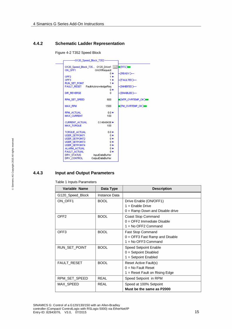
4.4 Speed Control –Telegram 352
4.4.1 Functionality
The G120 T352 Speed Block (also used in G130/G150) provides an interface forspeed control of a drive object in Sinamics via EtherNet/IP. The Drive is configuredfor control using Standard telegram type 352 which presets the drive speedreference and control word to be sourced from the communication interface. Inaddition there are four separate user defined control words/setpoints available; andfeedback for Current, Torque, Warning and Fault values.
4 Sinamics G Series Add-On Instructions
SINAMICS G: Control of a G120/130/150 with an Allen-Bradleycontroller (Compact/ ControlLogix with RSLogix 5000) via EtherNet/IPEntry-ID: 82843076, V3.0, 07/2015 15
ãS
iem
ens
AG
Cop
yrig
ht20
15A
llrig
hts
rese
rved
4.4.2 Schematic Ladder Representation
Figure 4-2 T352 Speed Block
4.4.3 Input and Output Parameters
Table 1 Inputs Parameters
Variable Name Data Type Description
G120_Speed_Block Instance DataON_OFF1 BOOL Drive Enable (ON/OFF1)
1 = Enable Drive0 = Ramp Down and Disable drive
OFF2 BOOL Coast Stop Command0 = OFF2 Immediate Disable1 = No OFF2 Command
OFF3 BOOL Fast Stop Command0 = OFF3 Fast Ramp and Disable1 = No OFF3 Command
RUN_SET_POINT BOOL Speed Setpoint Enable0 = Setpoint Disabled1 = Setpoint Enabled
FAULT_RESET BOOL Reset Active Fault(s)0 = No Fault Reset1 = Reset Fault on Rising Edge
RPM_SET_SPEED REAL Speed Setpoint in RPMMAX_SPEED REAL Speed at 100% Setpoint
Must be the same as P2000

4 Sinamics G Series Add-On Instructions
SINAMICS G: Control of a G120/130/150 with an Allen-Bradleycontroller (Compact/ ControlLogix with RSLogix 5000) via EtherNet/IPEntry-ID: 82843076, V3.0, 07/2015 16
ãS
iem
ens
AG
Cop
yrig
ht20
15A
llrig
hts
rese
rved
Variable Name Data Type Description
USER_SETPOINT1 INT User-defined word 1USER_SETPOINT2 INT User-defined word 2USER_SETPOINT3 INT User-defined word 3USER_SETPOINT4 INT User-defined word 4
Table 2 IN/OUT Parameters
Variable Name Data Type Description
DRV_CONTROL ARRAY Array of 6 integers referenced to the 6 outputswords of the drive telegram.
DRV_STATUS ARRAY Array of 6 integers referenced to the 6 inputwords of the drive telegram
Table 3 Output Parameters
Variable Name Data Type Description
RTS BOOL Ready to StartREADY BOOL Ready for OperationFAULTED BOOL Fault is ActiveINHIBITED BOOL Power On InhibitedENABLED BOOL Pulses are EnabledMTR_OVRTEMP_OK BOOL Motor Not OvertempPM_OVERTEMP_OK BOOL Power Module OvertempRPM_ACTUAL REAL Actual Speed in RPM *Set Scale Value to 100
for Percentage or set to P2000 ValueCURRENT_ACTUAL REAL Actual Current in AMP *Set Scale Value to 100
for Percentage or set to P2002 value
WORD INPUT OUTPUT
1 Control Word 1 Status Word 12 Speed Setpoint Value Actual Speed Value3 User- Defined ABS_Current4 User- Defined Torque5 User- Defined Warn_Code6 User-Defined Fault_Code

4 Sinamics G Series Add-On Instructions
SINAMICS G: Control of a G120/130/150 with an Allen-Bradleycontroller (Compact/ ControlLogix with RSLogix 5000) via EtherNet/IPEntry-ID: 82843076, V3.0, 07/2015 17
ãS
iem
ens
AG
Cop
yrig
ht20
15A
llrig
hts
rese
rved
4.5 EPOS Control
4.5.1 Functionality
The EPOS block interfaces to the Sinamics Basic Positioner via EtherNet/IP. TheEPOS Positioner is used for the absolute and relative positioning of linear androtary axes.The AOI provides a direct interface to EPOS control. The Sinamics G120/130/150List manual provides detailed explanation of all functionality available. Note thatdrive must be referenced before absolute positioning is allowed. State control andsequencing is not provided. Additional user logic is required to synchronize thestate of the drive with the positioning functions.The instruction interface provides easy access to basic drive control and to mostsignals and setpoints required for control of the MDI mode.
4.5.2 Schematic Ladder Representation
Figure 4-3 G120 EPOS Block

4 Sinamics G Series Add-On Instructions
SINAMICS G: Control of a G120/130/150 with an Allen-Bradleycontroller (Compact/ ControlLogix with RSLogix 5000) via EtherNet/IPEntry-ID: 82843076, V3.0, 07/2015 18
ãS
iem
ens
AG
Cop
yrig
ht20
15A
llrig
hts
rese
rved
4.5.3 Input and Output Parameters
Table 3 Input Parameter Data
Variable Name DataType
Description
S120_EPOS_BLOCK InstanceData
ON BOOL Drive Enable (ON/OFF1)FAULT_RESET BOOL Reset Active Fault(s)
0 = No Fault Reset1 = Reset Fault on Rising Edge
JOG_FWD BOOL 0 = No Jog1 = Jog Forward at speed in P2586
JOG_REV BOOL 0 = No Jog1 = Jog Reverse at speed in P2585
REF_START BOOL Referencing Start0 = No Referencing1 = Enable Referencing
MDI_START BOOL Enable MDI Mode0 = No MDI modeNote: All motion should be completed beforedisable to avoid fault.1 = Enable MDI Mode
MDI_SETUP BOOL Enable MDI Setup Mode0 = No Setup Mode1 = Enable MDI Setup Mode
MDI_POS_TYPE BOOL Select MDI Positioning Type0 = Absolute Positioning1 = Relative Positioning
MDI_FWD_DIR BOOL Enable Forward DirectionMDI_REV_DIR BOOL Enable Reverse Direction
Note: If Both MDI_FWD_DIR andMDI_REV_DIR are True, shortest path isselected for absolute positioning
MDI_EDGE_TRIG BOOL Trigger Loading of SetpointsLoad executed on rising edge of input transition
MDI_CONSTANT_TRIG BOOL Select Setpoint loading type0 = The setpoint are accepted on the rising edgeof the MDI_EDGE_TRIG input1 = Setpoints are continuously loaded. (AbsolutePositioning only)
INTERMEDIATE_STOP BOOL Stop motion. The canceling the motioncommand.0 = Stop motion1 = Allow motion
POSITION_SETPOINT DINT Position Setpoint in LUs

4 Sinamics G Series Add-On Instructions
SINAMICS G: Control of a G120/130/150 with an Allen-Bradleycontroller (Compact/ ControlLogix with RSLogix 5000) via EtherNet/IPEntry-ID: 82843076, V3.0, 07/2015 19
ãS
iem
ens
AG
Cop
yrig
ht20
15A
llrig
hts
rese
rved
Variable Name DataType
Description
ACCEL_RATE REAL Acceleration rate in LUs / s2
DECEL_RATE REAL Deceleration rate in LUs / s2V_OVERRIDE REAL Speed Setpoint in LUs / s
Table 4 Input/Output Parameter Data
Variable Name DataType
Description
DRV_CONTROL ARRAY Array of 12 integers referenced to the 12 outputswords of the drive telegram.
DRV_STATUS ARRAY Array of 12 Integers referenced to the 12 Inputwords for the drive Object.
Table 5 Output Parameter Data
Variable Name DataType
Description
RTS BOOL Ready to StartRDY_OP BOOL Ready for OperationENABLED BOOL Pulses are Enabled at Motor OutputFAULTED BOOL Fault is ActiveALARM BOOL Alarm is ActiveJOGGING BOOL Axis is JoggingHOMING BOOL Referencing Mode EnabledREFERENCED BOOL Axis is ReferencedMDI_POS BOOL MDI Mode is ActiveMDI_SETUP_ON BOOL MDI Setup Mode is ActiveTARGET_REACHED BOOL Position Actual is within the position window setFAULT_NUMBER INT Active Fault number. 0 if no FaultALARM_NUMBER INT Active Alarm Number. 0 if no AlarmPOSITION_ACTUAL DINT Position value in LUsSPEED_ACT_PCT REAL Speed in Percent of P2000TORQUE_ACTUAL REAL Torque value in percent of P2002
This value is mapped to word 12 of the telegramstatus data. For the torque to be displayedParameter 2051 Index 11 must be connected tor80.

4 Sinamics G Series Add-On Instructions
SINAMICS G: Control of a G120/130/150 with an Allen-Bradleycontroller (Compact/ ControlLogix with RSLogix 5000) via EtherNet/IPEntry-ID: 82843076, V3.0, 07/2015 20
ãS
iem
ens
AG
Cop
yrig
ht20
15A
llrig
hts
rese
rved
4.6 MDI Mode
4.6.1 Functionality
The MDI Mode AOI interfaces to the Sinamics EPOS positioner via EtherNet/IP.The EPOS positioner is used for the absolute and relative positioning of linear androtary axes.The AOI implements a state machine that allows the selection of three majormotion modes. The three modes are Velocity mode, Relative positioning, andAbsolute positioning mode.Velocity mode enables motion at a constant velocity set by the Speed referenceinput. The velocity setpoint can be changed while the axis is in motion The driveuses the Accel and Decel setpoints to reach the velocity setpoint. The mode isstarted by setting the VEL_MOVE input of the instruction.Jog forward and reverse is also available by setting the appropriate inputs to theinstructions. Jog velocity is set in the drive at parameters P2585 and P2586.Relative positioning mode allows the axis to travel for a specified distance set atthe position setpoint input of the instruction and selecting the REL_MOVE input.Absolute positioning mode moves the axis to a specified position by setting theposition value at the position setpoint input of the instruction and the setting theABS_MOVE input.
NOTICENote that the axis is not allowed to position until it has been referenced.

4 Sinamics G Series Add-On Instructions
SINAMICS G: Control of a G120/130/150 with an Allen-Bradleycontroller (Compact/ ControlLogix with RSLogix 5000) via EtherNet/IPEntry-ID: 82843076, V3.0, 07/2015 21
ãS
iem
ens
AG
Cop
yrig
ht20
15A
llrig
hts
rese
rved
4.6.2 Schematic Ladder representation
Figure 4-4 S120 MDI Block
4 Sinamics G Series Add-On Instructions
SINAMICS G: Control of a G120/130/150 with an Allen-Bradleycontroller (Compact/ ControlLogix with RSLogix 5000) via EtherNet/IPEntry-ID: 82843076, V3.0, 07/2015 22
ãS
iem
ens
AG
Cop
yrig
ht20
15A
llrig
hts
rese
rved
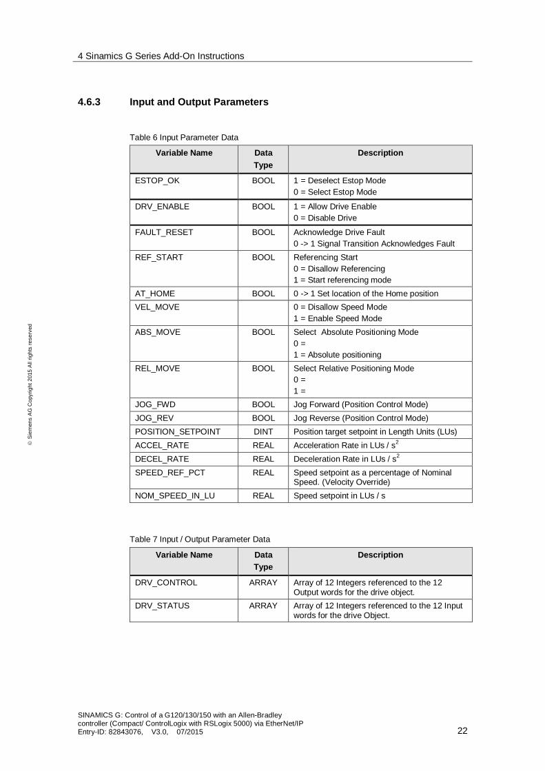
4.6.3 Input and Output Parameters
Table 6 Input Parameter Data
Variable Name DataType
Description
ESTOP_OK BOOL 1 = Deselect Estop Mode0 = Select Estop Mode
DRV_ENABLE BOOL 1 = Allow Drive Enable0 = Disable Drive
FAULT_RESET BOOL Acknowledge Drive Fault0 -> 1 Signal Transition Acknowledges Fault
REF_START BOOL Referencing Start0 = Disallow Referencing1 = Start referencing mode
AT_HOME BOOL 0 -> 1 Set location of the Home positionVEL_MOVE 0 = Disallow Speed Mode
1 = Enable Speed ModeABS_MOVE BOOL Select Absolute Positioning Mode
0 =1 = Absolute positioning
REL_MOVE BOOL Select Relative Positioning Mode0 =1 =
JOG_FWD BOOL Jog Forward (Position Control Mode)JOG_REV BOOL Jog Reverse (Position Control Mode)POSITION_SETPOINT DINT Position target setpoint in Length Units (LUs)ACCEL_RATE REAL Acceleration Rate in LUs / s2
DECEL_RATE REAL Deceleration Rate in LUs / s2
SPEED_REF_PCT REAL Speed setpoint as a percentage of NominalSpeed. (Velocity Override)
NOM_SPEED_IN_LU REAL Speed setpoint in LUs / s
Table 7 Input / Output Parameter Data
Variable Name DataType
Description
DRV_CONTROL ARRAY Array of 12 Integers referenced to the 12Output words for the drive object.
DRV_STATUS ARRAY Array of 12 Integers referenced to the 12 Inputwords for the drive Object.

4 Sinamics G Series Add-On Instructions
SINAMICS G: Control of a G120/130/150 with an Allen-Bradleycontroller (Compact/ ControlLogix with RSLogix 5000) via EtherNet/IPEntry-ID: 82843076, V3.0, 07/2015 23
ãS
iem
ens
AG
Cop
yrig
ht20
15A
llrig
hts
rese
rved
Table 8 Output Data Parameters
Variable Name DataType
Description
READY BOOL Ready to StartENABLED BOOL Pulse are Enabled at Motor OutputPOS_ACTIVE BOOL Positioning Mode is ActiveVEL_ACTIVE BOOL Velocity (Speed) mode is ActiveREFERENCED BOOL Axis is ReferencedFAULTED BOOL Drive Fault is ActiveHOMING BOOL Drive Alarm is ActiveTARGET_REACHED BOOL Position actual is within window set in driveFAULT_NUMBER INT Active Fault Number (0 = No Faults)ALARM_NUMBER INT Active Fault Number (0 = No Alarm)POSITION_ACTUAL DINT Actual Position Value in LUsSPEED_ACT_PCT REAL Speed in Percent of P2000TORQUE_ACTUAL REAL Torque Value in Percent of P2002
4.7 UDTs
UDTs are provided as representing the typical control and status words used forTelegrams implemented by the AOI provided. This cannot be utilized when usingthe provided EDS file. The UDTs can also be used independently to map IO datasent and received by the drive. The user application is able to directly control thetelegram words and bits to accomplish control concepts not included in the AOIsprovided by Siemens. This is the case when using user defined telegrams (freetelegram configuration with BICO) to exchange data with the drives.

5 Drive Configuration
SINAMICS G: Control of a G120/130/150 with an Allen-Bradleycontroller (Compact/ ControlLogix with RSLogix 5000) via EtherNet/IPEntry-ID: 82843076, V3.0, 07/2015 24
ãS
iem
ens
AG
Cop
yrig
ht20
15A
llrig
hts
rese
rved
5 Drive ConfigurationInitial commissioning of the G120/130/150 drives is not in the scope of thisdocument. Refer to the Sinamics G120/130/150 Getting Started Manual to assist inthe commissioning of the drive(s). This sample application referenced in thisdocument utilizes the Sinamics G120 training unit.
5.1 Configuration in STARTER
From Starter version 4.4 and G120 firmware 4.7.3 it is now possible to go onlinewhen the G120 is setup as for EIP communication. For the G130/150, it is possibleto go online from firmware 4.5 onwards, with a CBE20 option board.
5.1.1 Setting the IP Address through Edit Ethernet Node
Connect the Ethernet cable from the SINAMICS G120 interface X01 P2 (or one ofthe CBE20 ports on the CU320-2 DP/PN) to the Ethernet interface (port) of yourPG/PC. This should be the only Ethernet cable connected to the Sinamics G drive.
Set the IP address and the subnet mask of the Ethernet card of your PG/PC.Ensure that the subnet of your PC and G120/130/150 match.
1. Right Click your LAN adapter and select “Properties”2. Highlight the Internet Protocol item (this may be called TCP/IPv4)3. Click Properties4. Select “Use the following IP address”5. Enter in a unique IP address where the subnet matches the G120’s subnet.
The default IP address of the G120/130/150 is 0.0.0.0. Therefore, if this is thefirst commissioning of the drive, set your PG/PC’s IP address to 0.0.0.100 withthe subnet mask set to 255.255.255.0.

5 Drive Configuration
SINAMICS G: Control of a G120/130/150 with an Allen-Bradleycontroller (Compact/ ControlLogix with RSLogix 5000) via EtherNet/IPEntry-ID: 82843076, V3.0, 07/2015 25
ãS
iem
ens
AG
Cop
yrig
ht20
15A
llrig
hts
rese
rved
In STARTER, go to Options > Set PG/PC Interface…. select the TCP/IP interfaceparameterization. Click OK.
Go to Project > Accessible Nodes. If the window doesn’t automatically search fordrives on the network, click “Update”. Right-click the found drive unit and select“Edit Ethernet Node”.

5 Drive Configuration
SINAMICS G: Control of a G120/130/150 with an Allen-Bradleycontroller (Compact/ ControlLogix with RSLogix 5000) via EtherNet/IPEntry-ID: 82843076, V3.0, 07/2015 26
ãS
iem
ens
AG
Cop
yrig
ht20
15A
llrig
hts
rese
rved
1. Enter the desired IP address and Subnet Mask. Ensure the IP address hasthe same subnet as the Logix controller
2. Press the Assign IP Configuration button.3. After completing the IP configuration assignment, enter the device name.4. Assign this to the SINAMICS G120/130/150 drive by pressing the Assign
Name button.5. Close the screen by pressing the Close button.

5 Drive Configuration
SINAMICS G: Control of a G120/130/150 with an Allen-Bradleycontroller (Compact/ ControlLogix with RSLogix 5000) via EtherNet/IPEntry-ID: 82843076, V3.0, 07/2015 27
ãS
iem
ens
AG
Cop
yrig
ht20
15A
llrig
hts
rese
rved
5.1.2 G120 Parameter Setting for EtherNet/IP Communication
1. Go online with the drive via Profinet/Ethernet connection and navigate to theexpert list.
2. Change the following parameter to configure for Ethernet/IP:· p2030 = [10] EtherNet/IP
3. Copy RAM to ROM4. Upload the G120 to the PG/PC5. Power-cycle the control unit
The G120 is now set to operate as an EtherNet/IP adapter.
h
NOTE When using AOI’s with the generic Ethernet module, p8980 = [0] SINAMICS
When using an EDS file, then set p8980 = [1] ODVA AC/DC
1 2 3

5 Drive Configuration
SINAMICS G: Control of a G120/130/150 with an Allen-Bradleycontroller (Compact/ ControlLogix with RSLogix 5000) via EtherNet/IPEntry-ID: 82843076, V3.0, 07/2015 28
ãS
iem
ens
AG
Cop
yrig
ht20
15A
llrig
hts
rese
rved
5.1.3 G130/150 Parameter Settings for EtherNet/IP Communication
1. Go online with the drive via Profinet/Ethernet connection and navigate to theexpert list.
2. Change the following parameters to configure for Ethernet/IP:· P8835 = [4] EtherNet/IP
3. Copy RAM to ROM4. Upload the G130/150 to the PG/PC5. Power-cycle the control unit
The G130/150 is now set to operate as an EtherNet/IP adapter.
Figure 5-1 Selection of EtherNet/IP at P8835
Using a CU320-2 PN and a CBE20
When a CBE20 is installed in a CU320-2 PN it is important to note that theconfiguration of the Communication Option Module is not preselected as primaryinterface (IF1). In the configuration process of the CU the Option module must beselected as the first interface as shown in the figure below. This can also beselected with parameter P8839.

5 Drive Configuration
SINAMICS G: Control of a G120/130/150 with an Allen-Bradleycontroller (Compact/ ControlLogix with RSLogix 5000) via EtherNet/IPEntry-ID: 82843076, V3.0, 07/2015 29
ãS
iem
ens
AG
Cop
yrig
ht20
15A
llrig
hts
rese
rved
Figure 5-2 Selecting Optional Communication module as PZD Interface 1 (IF1)
NOTE If you are using a standard AOI (e.g. with telegram 1, 352, 111), make sure youset p922 = [1], [352], or [111].

5 Drive Configuration
SINAMICS G: Control of a G120/130/150 with an Allen-Bradleycontroller (Compact/ ControlLogix with RSLogix 5000) via EtherNet/IPEntry-ID: 82843076, V3.0, 07/2015 30
ãS
iem
ens
AG
Cop
yrig
ht20
15A
llrig
hts
rese
rved
5.2 Using a Freely Configurable Telegram
It is possible to configure a custom telegram to fit a specific applicationrequirement. The custom configuration can be accomplished by one of severalmethods listed.1. Using a standard telegram as a template and changing the configuration
manually.2. Selecting the input and output data length and connecting the telegram words
in the communications window of the drive configuration.3. Configuration by Script execution. A script can be written in Starter which
configures the telegram size and connections required. The script is thenexecuted in Starter configuring the drive.
Parameter r2067 displays the number of PZDs the controller detected to be part ofthe telegram for the Drive Object. The Input and Output data length must match thevalues calculated by the controller in r2067 of the specified Drive Object.
Figure 5-3 Number of Interconnected PZDs
NOTICE When changing from a standard telegram to a freely configurable telegram,you must cycle the power of the drive to ensure a correct configuration.
Parameter r2067 is only calculated on a power-up of the drive. In order for theCU to correctly calculate parameter r2067, all of the PZD of the telegram mustbe interconnected.
*For example if you are using Telegram 352 and change to Free-BICO telegram(P922 =999) then the four freely configurable input value to the drive must beterminated to “Dummy” parameters if they are not used for actual parameterconnection – such as torque limit or added speed.

6 Configuring a Generic Ethernet Module
SINAMICS G: Control of a G120/130/150 with an Allen-Bradleycontroller (Compact/ ControlLogix with RSLogix 5000) via EtherNet/IPEntry-ID: 82843076, V3.0, 07/2015 31
ãS
iem
ens
AG
Cop
yrig
ht20
15A
llrig
hts
rese
rved
6 Configuring a Generic Ethernet Module6.1 Adding a new module in RSLogix
A Generic IO module is used to configure the cyclic data exchange between theautomation controller and the Sinamics drive without an EDS file.
6.1.1 Inserting the module in an RSLogix project
Table 1 Inserting the Module
1. Insert a module by right clicking thenetwork interface in the IO configurationsection of the Project tree.
2. In the “Select Module” dialog box use theFind function to search for the term“GENERIC”. Select the “Generic EthernetModule” module to be inserted.

6 Configuring a Generic Ethernet Module
SINAMICS G: Control of a G120/130/150 with an Allen-Bradleycontroller (Compact/ ControlLogix with RSLogix 5000) via EtherNet/IPEntry-ID: 82843076, V3.0, 07/2015 32
ãS
iem
ens
AG
Cop
yrig
ht20
15A
llrig
hts
rese
rved
6.1.2 Configuring network parameters
Table 2 Configuring the Network Parameters
The module name should identify theG120/130/150 to allow easy selection fromother modules configured in the controller.It is also the name used for the controllerlevel tag that will hold the data. Use theDescription box to describe the Driveobjects contained in the module.
The data exchange format should be set toInteger (INT).Enter the IP Address of the G120/130/150.The Connection Parameters sectionconfigures the IO Assemblies. TheAssembly Instances should always be 101through 103 for the Input, Output andConfiguration Assembly respectively. Thesize of the Input and Output assemblies isthe total number of words. For StandardTelegram 1, there are two words in and twowords out. For Telegram 352 there are 6in 6 out.In this example the speed block telegramfor T352 is shown.
6.1.3 Connection Parameters
Table 3 Setting the Connection Parameters
1. The Requested Packet Interval (RPI) isthe rate at which the controller willexchange data with the drive. TheG120/130/150 can operate with a RPIset to a minimum of 5 ms. In thisapplication we will use a value of 10 ms.
2. 2) Unicast is selected as the exchangemethod.

6 Configuring a Generic Ethernet Module
SINAMICS G: Control of a G120/130/150 with an Allen-Bradleycontroller (Compact/ ControlLogix with RSLogix 5000) via EtherNet/IPEntry-ID: 82843076, V3.0, 07/2015 33
ãS
iem
ens
AG
Cop
yrig
ht20
15A
llrig
hts
rese
rved
6.1.4 Using the IO Data
The IO data is available as an array of integers in the controller tags section of theproject tree. They are included as a tag list with the L5K file.
Figure 6-1 Controller Tags for new module

7 Using AOIs in a New Application
SINAMICS G: Control of a G120/130/150 with an Allen-Bradleycontroller (Compact/ ControlLogix with RSLogix 5000) via EtherNet/IPEntry-ID: 82843076, V3.0, 07/2015 34
ãS
iem
ens
AG
Cop
yrig
ht20
15A
llrig
hts
rese
rved
7 Using AOIs in a New Application7.1 Importing AOIs
The AOIs provided with the sample application can be easily integrated into a newor existing user program by importing the instructions using L5K files.
7.1.1 Installing L5K Files in RSLogix
Table 1 Steps to Importing the AOIs
3. Import the AOI into the Add OnInstructions folder. Right click the Add-On Instructions folder in the project treeand select the Import Add-OnInstruction option.
4. Select the required L5K file for thedesired Instruction and click Import.Review the Import configuration andclick OK.
5. The Project should now show theimported Instruction. Notice that UDTsrequired for the instruction have alsobeen imported. These UDTs can alsobe used to create additional variablesand aliases.

7 Using AOIs in a New Application
SINAMICS G: Control of a G120/130/150 with an Allen-Bradleycontroller (Compact/ ControlLogix with RSLogix 5000) via EtherNet/IPEntry-ID: 82843076, V3.0, 07/2015 35
ãS
iem
ens
AG
Cop
yrig
ht20
15A
llrig
hts
rese
rved
7.2 Using the AOI
7.2.1 Adding AOI to an RSLogix Program
Table 2 Using the G120 Simple Speed Block
6. Add AOI to a new rung bydragging from project tree.
7. Declare and assign instancedata variable. The new tag canbe created as a local programtag with a name that clearlyidentifies the drive data. Rightclick the field next toG120_Speed_Block and selectNew Tag.
8. Give the tag a descriptive nameand select OK

7 Using AOIs in a New Application
SINAMICS G: Control of a G120/130/150 with an Allen-Bradleycontroller (Compact/ ControlLogix with RSLogix 5000) via EtherNet/IPEntry-ID: 82843076, V3.0, 07/2015 36
ãS
iem
ens
AG
Cop
yrig
ht20
15A
llrig
hts
rese
rved
7.2.2 I/O Interface
Connecting the instruction to the Controller IO tags is accomplished by moving theIO data into the AOI Interface.Figure 7-1
The second rung holds the AOI. The local variables “InputDataBuffer” and“OutputDataBuffer” are used as storage for the AOI to receive and send data to theController IO tags.The first rung copies the IO data for the drive to a local variable to be used by theAOI as inputs in the “DRV_STATUS” parameters. “DRV_STATUS” and“DRV_CONTROL” is declared as INOUT parameters and therefore passed byreference.The third rung holds the copy command that moves the control data from theworking variable “OutputDataBuffer” to the controller IO tag.All AOIs provided will use this method of data exchange with IO containing thedrive data. Additional access to the control data can be performed before the datais copied to the IO Tag. This allows the user to utilize features already mapped inthe telegram that are not control by the AOI. In a similar manner the Status datacan be access by the user program.

8 Drive Parameter Access
SINAMICS G: Control of a G120/130/150 with an Allen-Bradleycontroller (Compact/ ControlLogix with RSLogix 5000) via EtherNet/IPEntry-ID: 82843076, V3.0, 07/2015 37
ãS
iem
ens
AG
Cop
yrig
ht20
15A
llrig
hts
rese
rved
8 Drive Parameter Access8.1 Explicit Messaging
In many applications it is necessary to read or write parameters in the drive. Thisallows increased flexibility in implementation of the machine functionality.To allow this occasional (acyclic) data exchange of drive and motor parameters,the drive supports explicit messaging.
The MSG instruction can read from or write to a parameter by accessing the drive’scommunication object. When parameterizing the MSG instruction, below are someimportant parameters:
Class = 401hex (for G120)
On the G130/150:CU class = 401hexDrive class = 402hex
Instance = parameter number p1027 = instance 1027
Attribute = parameter index number (hex) Index 0 = attribute 0 Index 1 = attribute 1 … Index 65535 = attribute FFFFh
Get attribute single = read a parameterSet attribute single = write a parameter

8 Drive Parameter Access
SINAMICS G: Control of a G120/130/150 with an Allen-Bradleycontroller (Compact/ ControlLogix with RSLogix 5000) via EtherNet/IPEntry-ID: 82843076, V3.0, 07/2015 38
ãS
iem
ens
AG
Cop
yrig
ht20
15A
llrig
hts
rese
rved
8.2 Using the MSG Instruction
NOTE It is a good idea to one-shot the message requests (e.g. with a flasher). If therung for the MSG instruction is always true, the communication board can getoverwhelmed and fault out.
Table 1 Parameterizing the MSG Instruction
1. MSG Instruction:Insert the MSG instruction.
2. Instruction Tag:Create a controller scope tag forthe instruction in the Tag tab of themessage configuration dialog box.This tag contains the workingmemory area for the MSGinstruction.
3. Message Type:Select the CIP Generic messagetype.

8 Drive Parameter Access
SINAMICS G: Control of a G120/130/150 with an Allen-Bradleycontroller (Compact/ ControlLogix with RSLogix 5000) via EtherNet/IPEntry-ID: 82843076, V3.0, 07/2015 39
ãS
iem
ens
AG
Cop
yrig
ht20
15A
llrig
hts
rese
rved
4. Service Type:Select “Get Attribute Single” to readand parameter or “Set AttributeSingle” to write the parameter.
5. Class:401 (hex)
6. Instance:This is the parameter number ofthe object, in Starter. E.g. DC Linkvoltage (p26).

8 Drive Parameter Access
SINAMICS G: Control of a G120/130/150 with an Allen-Bradleycontroller (Compact/ ControlLogix with RSLogix 5000) via EtherNet/IPEntry-ID: 82843076, V3.0, 07/2015 40
ãS
iem
ens
AG
Cop
yrig
ht20
15A
llrig
hts
rese
rved
7. Attribute:This is the parameter index. Forparameters without an index, use“0”.
8. Destination:For reading a parameter select aController scope tag where thevalue will be written
If writing a value to the parameter,select a tag in the Source elemententry.
9. Source Length (writing only):When writing to a parameter, makesure the source length matches theparameter that you are trying towrite to.
INT = 2 Bytes (16 bit)REAL = 4 Bytes (32 bit)

8 Drive Parameter Access
SINAMICS G: Control of a G120/130/150 with an Allen-Bradleycontroller (Compact/ ControlLogix with RSLogix 5000) via EtherNet/IPEntry-ID: 82843076, V3.0, 07/2015 41
ãS
iem
ens
AG
Cop
yrig
ht20
15A
llrig
hts
rese
rved
10. Make sure the data type of the tag(source/destination) matches thedata type of the parameter.
INT = 2 Bytes (16 bit)REAL = 4 Bytes (32 bit)
11. To figure out the data type of theparameter, search for theparameter in the Starter help tool,or refer to the list manual.
12. Path:In the communication tab enter thename of the IO node for theG120/130/150. Use the Browseoption to find the node in theproject tree.

9 Troubleshooting
SINAMICS G: Control of a G120/130/150 with an Allen-Bradleycontroller (Compact/ ControlLogix with RSLogix 5000) via EtherNet/IPEntry-ID: 82843076, V3.0, 07/2015 42
ãS
iem
ens
AG
Cop
yrig
ht20
15A
llrig
hts
rese
rved
9 TroubleshootingI can’t go online with the drive in Starter using the Ethernet cable.Do you have firmware v4.7 on the drive unit? Communication from Starter to thedrive using Ethernet/IP is only support with firmware v4.7 or later on the G120. Ifyou are using v4.6, then you will need to use the USB cable to connect to the drivewith Starter.
On the G130/150, EtherNet/IP communication is supported with a CBE20 andfirmware v4.5 or later.
The drive and the PLC are not communicating.
1. Check the LED lights.a. PLC: Is the I/O light solid green?b. G120: Is the Link1 light solid green?c. G130/G150/S120: Is the OPT light solid green?d. This means that the drive is communicating and it is another issue.
2. Is Drive set for EIP (G120: p2030 = 10, G130/G150/S120: p8835 = 4)?a. A power cycle is required after changing p2030/p8835.b. For drives with CU320-2 (G130/G150/S120), the PLC must be
connected through the CBE20 card on the drive.
3. Are there duplicate IP addresses on the network?a. Verify IP addresses (accessible nodes, PST, edit Ethernet nodes, etc.)

9 Troubleshooting
SINAMICS G: Control of a G120/130/150 with an Allen-Bradleycontroller (Compact/ ControlLogix with RSLogix 5000) via EtherNet/IPEntry-ID: 82843076, V3.0, 07/2015 43
ãS
iem
ens
AG
Cop
yrig
ht20
15A
llrig
hts
rese
rved
4. Did you parameterize the Generic Ethernet Module in RSLogix 5000 correctly?
a. Do you have the “Comm. Format” set to Data –INT, or accidentally setto Data-DINT?
b. Do the Connection Parameters (addresses and length) match the drivetelegram?
i. If you are using an EDS, it is for Telegram 1 only. If anotherTelegram is needed, use a generic Ethernet device.
5. Could it be a bad Ethernet cable?
6. Are there faults on the drive?a. Check LED’s status on the driveb. Check diagnostics on drive for faults.

9 Troubleshooting
SINAMICS G: Control of a G120/130/150 with an Allen-Bradleycontroller (Compact/ ControlLogix with RSLogix 5000) via EtherNet/IPEntry-ID: 82843076, V3.0, 07/2015 44
ãS
iem
ens
AG
Cop
yrig
ht20
15A
llrig
hts
rese
rved
7. Are all Drive Enables (OFF1/OFF2/OFF3) enabled?
There is no information on the control/status of the AOI’s even though thedrive and the PLC are set up correctly (no faults, green lights on LED’s).
On the G130/G150/S120 check that you have the CBE20 set up on the control unitas IF1.

10 Glossary
SINAMICS G: Control of a G120/130/150 with an Allen-Bradleycontroller (Compact/ ControlLogix with RSLogix 5000) via EtherNet/IPEntry-ID: 82843076, V3.0, 07/2015 45
ãS
iem
ens
AG
Cop
yrig
ht20
15A
llrig
hts
rese
rved
10 GlossaryAOI (Add On Instruction): Commonly used logic for a task that is encapsulated into a block tobe reused in RSLogix programs
BICO: BICO technology (Binector Connector Technology) allows the drive to be adapted to awide variety of requirements. Digital and analog signals which can be connected freely bymeans of BICO parameters, are identified by the prefix BI, BO, CI or CO in their parametername.
Control Word: Arrangement of two bytes used to command the drive sequence control(referred to as STW1 in SINAMICS Documentation)
EDS File: Text files used by RSLogix network configuration tool to help identify products andeasily integrate them on a network. All available G120/130/150 EDS files can be found here:http://support.automation.siemens.com/WW/llisapi.dll?func=cslib.csinfo&lang=en&objid=78026217&caller=nl
Free Telegrams: The send and receive telegrams can be configured as required by using BICOtechnology to interconnect the send and receive process data.
L5K file: File type used for importing an AOI into RSLogix program
MDI (Motion Direct Input): Direct setpoint input function for positioning
ODVA: Open DeviceNet Vendors Association. Organization that supports network technologiesbuilt on the Common Industrial Protocol (CIP™) — DeviceNet™, EtherNet/IP™, CompoNet™,and ControlNet™
PN Interface: PROFINET interface
PROFIdrive: Device profile to provide standardization of drive telegram type thus minimizingintegration and commissioning time and effort.
Siemens Standard Telegrams: Structured in accordance with manufacturer specification withthe internal process data links automatically set up in accordance with the telegram numbersetting.
Standard PROFIdrive Telegrams: Structured in accordance with PROFIdrive profile with theinternal process data links automatically set up in accordance with the telegram number setting.
STARTER: Software for Siemens Sinamics drives configuration and diagnostics
Status Word: Arrangement of two bytes used to report the current status of the drive (referredto as ZSW1 in SINAMICS Documentation)
Telegram type 1: Standard PROFIdrive telegram of two words for simple speed control
Telegram type 2: Standard PROFIdrive telegram of six words for vector speed control
UDT: User Defined Type holds data relevant to the device
Vector mode: Axis control type including closed loop, open loop, and V/Hz speed control.Typically used with induction motors to obtain high speed and low torque ripple.

11 History
SINAMICS G: Control of a G120/130/150 with an Allen-Bradleycontroller (Compact/ ControlLogix with RSLogix 5000) via EtherNet/IPEntry-ID: 82843076, V3.0, 07/2015 46
ãS
iem
ens
AG
Cop
yrig
ht20
15A
llrig
hts
rese
rved
11 HistoryTable 11 History
Version Date Changes
V1.0 05.28.2013 Initial ReleaseV1.2b 10.17.2014 Draft for RevisionV2.0 03.26.2015 Add in explicit messaging
Added in troubleshootingV3 07.02.2015 Added in G130/G150 information
Removed references to USB connectionRemoved the appendix and added the “edit ethernet node”to the main documentationUpdated T352 blockAdded in T111 block